

Page 1

IP
Telephone System
GATEWAY
INSTALLATION
GUIDE
Page 2

Page 3

Table of Contents
Introduction..................................1
About this Guide..........................1
Line Power Requirements...........1
Compliance .................................2
Overview.......................................2
Venture IP Gateway Hardware ....2
Power..........................................3
Network Connections..................3
External Paging...........................3
Music on Hold ............................3
Phone Lines ................................4
Bypass Port ................................4
LED .............................................4
Technical Specifications.............4
Installation...................................5
Maintenance and Repair.............5
Troubleshooting ...........................6
Limited Warranty ..........................7
Table of Contents
Page 4
Introduction
About this Guide
This guide specifically addresses the installation and technical specifications
of the VentureIP Gateway. The
detailed technical instructions regarding network installation, configuration,
downloads and set management. The
basic installation instructions and describes all user-enabled features for
the VentureIP 480i telephone.
Line Power Requirements
The Venture IP Gateway operates from an 802.3af Power over Ethernet (PoE)
Introduction
unit or from the provided 48VDC/0.2A wall adaptor.
CAUTION: The socket outlet, if used, shall be located near the equipment
and shall be easily accessible by the user.
CAUTION: Only CSA/UL approved power adaptors shall be used.
NOTE: The Venture IP Gateway does not require a power adapter if the
LAN cable is IEEE 802.3af, Power over LAN enabled.
VentureIP 480i System Guide
VentureIP 480i User Guide
offers more
provides
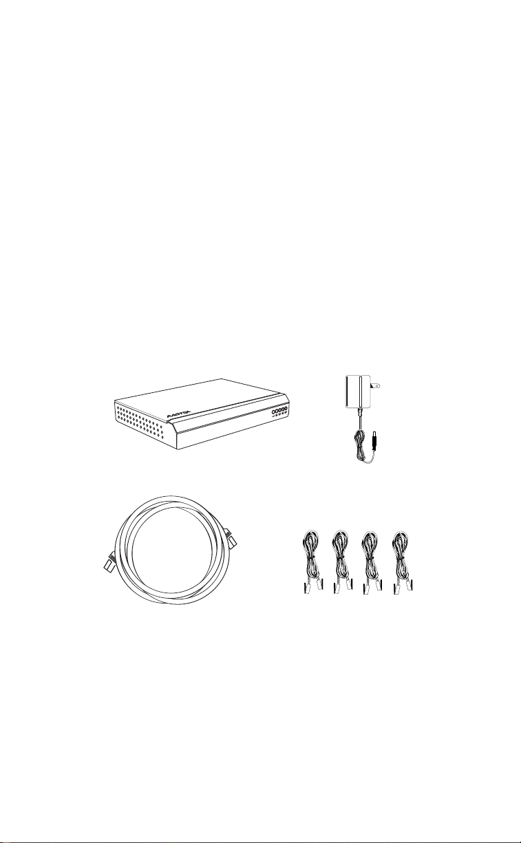
gateway
Ethernet Cable
1 Model Venture IP Gateway Installation Guide
power supply
Four Line Cords
Page 5

Compliance
The Venture IP Gateway is a Class B device that complies with Part 68
and Part 15 of the FCC Rules, and Canadian requirements CS-03 and
ICES-003 Class B EMI requirements. Operation is subject to the following two
conditions: (1) this device may not cause harmful interference and (2) this
device must accept any interference received, including interference
that may cause undesirable operation.
Overview
The Venture IP Gateway provides a connection with the local telephone
network (PSTN). See Figure 1. The Venture IP Gateway is added to the
network the same way as a telephone: simply plug it in.
The Venture IP Gateway supports up to four telephone lines. Multiple Venture
IP Gateways can exist in the same network, which increases the number of
available ports.
Figure 1: Network Configuration
4
4
8
8
0
0
4
8
4
8
0
0
Venture IP Gateway Hardware
Venture IP Gateway Hardware
This section describes the Venture IP Gateway hardware, including:
• Power
• Network Connections
• Paging
• Music on Hold
• Phone Lines
• Bypass Port
• LEDs
• Technical Specifications
Model Venture IP Gateway Installation Guide
2
Page 6

Figure 2: Venture IP Gateway Front View
L
L
L
L
L
L
SYS
Figure 3: Venture IP Gateway Rear View
Power
The Venture IP Gateway operates from an 802.3af Power over Ethernet
(PoE) unit or from the provided 48VDC/0.2A wall adaptor.
Network Connections
Venture IP Gateway Hardware
The Venture IP Gateway has two Ethernet connections: a LAN port and a
WAN port. Both use RJ-45 connectors. The LAN connects to the internal IP
network; the WAN port is for future use. Each port is 10/100Base-T.
Each port has two LEDs: a Link and Activity LED (left of the port) and a
Speed LED (right of the port). See Figure 3. The Link and Activity LED
indicates a link when lit solid green; it indicates activity when flashing green.
The Speed LED indicates 10Base-T when off; it indicates 100Base-T when
lit solid yellow.
External Paging
The Venture IP Gateway has an Audio Output jack for paging. It uses a
standard 3.5 mm stereo mini-jack. Ensure that the volume is set to 50%.
Music on Hold
The Venture IP Gateway has a Music Input jack for Music on Hold (MOH).
It uses a standard 3.5 mm stereo mini-jack. Ensure that the music source
volume is set to 50%.
3 Model Venture IP Gateway Installation Guide
Page 7

Phone Lines
The Venture IP Gateway has four phone lines numbered 1 through 4.
The RJ-11 cables connect to the telephone network through your
Service Provider.
Bypass Port
An analog telephone set can be plugged into the Bypass Port. In case of
power failure to the Gateway, the analog telephone becomes operational to
let you keep your connection to the telephone network. In the event of a
power failure Line 1 connects to the Bypass port internally.
Note:
Please ensure a phone line is connected to Line 1.
LED
There are five LEDs on the front of the Venture IP Gateway. The left-most
LED is the system LED. It turns red on start-up and changes to green when
the system is up and running. The other four LEDs reflect the status of the
phone lines. If an LED is off, the line is not connected or unavailable. If an
LED is green, the line is connected and available. If an LED is flashing
green, the line is connected but in use.
Technical Specifications
Analog Ports 4FXO Ports, 1 Emergency Bypass Port,
RJ11/RJ45 Plug Types
Network Ports 100 Base-T; RJ-45 Connector
Music Input Standard 3.5 mm stereo mini-jack
Audio Output (Paging) Standard 3.5 mm stereo mini-jack
CODEC Options G.711 PCM, G.723.1, G.729A
Power ETF 802.3af Power over Ethernet
48VDC/0.2A Wall plug (optional)
Certifications CSA C22.2 No.60950 NRTL/C,
FCC Part 15, Subpart B Class B,
TIA/EIA-968, ICES-003, CS-03
Weight 1.9 lbs (.8 kg)
Operating Temperature/
Humidity
Storage Temperature/
Humidity
32° F to 104° F (0° C to 40° C)
10% to 95% non condensing
14° F to 140° F (-10° C to 40° C)
5% to 90% non condensing
Technical Specifications
Model Venture IP Gateway Installation Guide
4
Page 8

Installation
To install the Venture IP Gateway, follow these steps:
1.
Select a flat, well-ventilated space.
2.
If you have 802.3af PoE, plug in your Ethernet cable to the LAN port and
the unit will power up.
3.
If you don’t have PoE, plug in the provided 48VDC/0.2A wall adaptor and
plug your Ethernet cable in to the LAN port.
The unit will power up.
4.
Plug in your phone line(s).
Installation
Note:
Plug an analog phone into the Bypass port to ensure your phone
connection is not interrupted in the event of a power failure. There is no dial
tone while the Venture IP Gateway has power.
The system LED turns red on start-up and changes to green when the
system is up and running.
Maintenance and Repair
The Venture IP Gateway is a field replaceable unit. There are no
user-serviceable parts inside the switch. For repairs, return the unit to
Aastra Technologies.
5 Model Venture IP Gateway Installation Guide
Page 9

Troubleshooting
The lights at the LAN port are off or blinking
The lights on the LAN port indicate the port's speed, status, and activity.
Refer to LEDs on page 5 for a description of these indicators.
The SYS light is solid red
A red SYS light indicates that the Venture IP Gateway is booting and is not
yet ready to make external calls. Check to ensure that the LAN port is
connected and that there is at least one phone line connected to the unit.
A phone line is connected, but the LINE light for that port is off
The LINE light indicates the status of the respective phone line connected to
the Venture IP Gateway PSTN interface. (See LEDs on page 5 for details).
Ensure that the phone line is not already in use by another analog telephone.
Verify that the phone line is functioning properly by connecting an analog
telephone to the line and listening for dial tone.
There's no dial tone on the phone when plugged into the Bypass port
An analog telephone connected to the Bypass port works only when
power is removed from the Venture IP Gateway. Ensure that a phone line
is connected to Line 4 of the Venture IP Gateway.
Troubleshooting
Model Venture IP Gateway Installation Guide
6
Page 10

Limited Warranty
Aastra Telecom warrants this product against defects and malfunctions during a one
(1) year period from the date of original purchase. If there is a defect or malfunction,
Aastra Telecom shall, at its option, and as the exclusive remedy, either repair or
replace the telephone set at no charge, if returned within the warranty period.
If replacement parts are used in making repairs, these parts may be refurbished, or
may contain refurbished materials.
If it is necessary to replace the telephone set, it may be replaced with a refurbished
telephone of the same design and color. If it should become necessary to repair or
replace a defective or malfunctioning telephone set under this warranty, the
provisions of this warranty shall apply to the repaired or replaced telephone set until
the expiration of ninety (90) days from the date of pick up, or the date of shipment to
you, of the repaired or replacement set, or until the end of the original warranty
period, whichever is later. Proof of the original purchase date is to be provided with all
telephone sets returned for warranty repairs.
Exclusions
Aastra Telecom does not warrant its telephone sets to be compatible with the
Limited Warranty
equipment of any particular telephone company. This warranty does not extend to
damage to products resulting from improper installation or operation, alteration,
accident, neglect, abuse, misuse, fire or natural causes such as storms or floods, after
the telephone is in your possession.
Aastra Telecom shall not be liable for any incidental or consequential damages,
including, but not limited to, loss, damage or expense directly or indirectly arising
from the customers use of or inability to use this telephone, either separately or in
combination with other equipment. This paragraph, however, shall not apply to
consequential damages for injury to the person in the case of telephones used or
bought for use primarily for personal, family or household purposes.
This warranty sets forth the entire liability and obligations of Aastra Telecom with
respect to breach of warranty, and the warranties set forth or limited herein are the
sole warranties and are in lieu of all other warranties, expressed or implied, including
warranties or fitness for particular purpose and merchantability.
Warranty Repair Services
Should the set fail during the warranty period;
In North America
Outside North America
You will be responsible for shipping charges, if any. When you return this telephone
for warranty service, you must present proof of purchase.
After Warranty Service
Aastra Telecom offers ongoing repair and support for this product. This service
provides repair or replacement of your Aastra Telecom product, at Aastra Telecom's
option, for a fixed charge. You are responsible for all shipping charges. For further
information and shipping instructions;
In North America
Outside North America
Repairs to this product may be made only by the manufacturer and its authorized
Note:
agents, or by others who are legally authorized. This restriction applies during and after
the warranty period. Unauthorized repair will void the warranty.
, please call 978-436-4111 for further information.
, contact your sales representative for return instructions.
, contact our service information number: 978-436-4111.
, contact your sales representative.
7 Model Venture IP Gateway Installation Guide
Page 11

A
About this Guide 1
Index
B
Bypass Port 4
C
Compliance 2
E
External Paging 3
I
Installation 5
L
LED 4
Line Power Requirements 1
M
Maintenance and Repair 5
Music on Hold 3
N
Network Connections 3
O
Overview 2
P
Phone Lines 4
Power 3
T
Technical Specifications 4
Troubleshooting 6
V
Venture IP Gateway Hardware 2
W
Warranty 7
Index
Page 12

If you’ve read this owner’s manual and consulted the Troubleshooting section and
still have problems, please visit our website at www.aastra.com or call 978-436-4111 for
technical assistance.
© Aastra Telecom Inc. 2005 41-0086-00 Rev 00
 Loading...