

Page 1

Administrator’s Guide
UniData IPW2000 Office IP Phone
For ERICSSON WebSwitch 2000 , version 3.0 and later
Page 2

Copyright Notice
EN/LZT 108 6349
Copyright UniData Communication Systems, Inc 2002.
All rights reserved
No part of this publication may be reproduced, transmitted, transcribed, stored in a
retrieval system, or translated into any language in any form by any means without
prior written permission of the UniData Communication Systems, Inc.
UniData Communication Systems reserves the right to revise this documentation and
to make changes in content from time to time without obligation on the part of
UniData Communication Systems to provide notification of such revision or change.
UniData Communication Systems provides this documentation without warranty,
term, or condition of any kind, either implied or expressed, including, but not limited
to, the implied warranties, terms, or conditions of merchantability, satisfactory quality,
and fitness for a particular purpose. UniData Communication Systems may make
improvements or changes in the product(s) and/or the program(s) described in this
documentation at any time.
Declaration of conformity
Hereby, Ericsson Enterprise AB, declares that this telephone, is in conformity with
the essential requirements and other relevant provisions of the European R&TTE
directive 1999/5/EC.
Details to be found at: http://www.ericsson.com/sdoc.
Page 3

Table of Contents
Safety Information………………………………………………..
Introduction to IPW2000………………………………………….
Installation ……………………………..………………………...
Connect the Cable…………………………..………………
Place the Phone………………………………………….….
Use the Headset……………………………………………..
Set the Network Connection………………………………..…..
Set the DHCP Mode………………………………………..
Set the Manual IP…………………………………………..
Set the Load Option……………………………………………...
Set the Load Option from DHCP…………………………..
Set the Load Option from TFTP. …………………………..
Set the Load Option from File System…………………….
Change the Administrator Password…………………………..
Factory Default and Clearing Password…..…………………
Upgrade the Software……………………………………………
TFTP Auto Upgrade………...……………………………….
Manual upgrade through TFTP server……………………
TFPT Upgrade through power reset………………………
Modify Software Parameters……………….…………………..
Modify the user.ini File ……………….………….………...
Modify the loadrun.ini File…………….…………….……..
Change the Voice Settings………………………….…………..
Product Specifications………………….………………………..
Glossary……………………………………………….…………..
Page
1
2
3
3
4
4
5
5
7
10
10
11
12
13
14
15
15
16
19
20
20
23
24
25
28
i IPW2000
Page 4

Safety Information
The Utmost care and attention has been devoted to quality standards in the
manufacture of your new IPW-2000. Safety is a major factor in the design of
every set. But, safety is your responsibility too.
Use Power over LAN IEEE 802.3af compliant.
Use the adaptor .
(Output: DC 18V 600mA ~ 48V 225mA, (-)---(o---(+))
For your safety
To reduce the risk of an electrical shock, do not disassemble this phone.
There are no user serviceable parts. Opening or removing covers may expose you
to hazardous voltages. Incorrect reassembly may cause an electrical shock.
Never push objects of any kind into this phone’s housing slots since such objects
may touch hazardous voltage points or short out parts that may cause electrical
shock.
Adjust only those controls covered in this Administrator’s Guide. Improper
adjustment of other controls may result in damage and could require extensive
repair by a qualified service personnel to restore this phone
Protection of the Telephone
Only use an Unshielded Twisted Pair (UTP) Category 5 Ethernet cable when
connecting to this phone’s RJ-45 ports (Uplink and Downlink).
Always use this phone with the required power source. The proper power source
required for this phone is written on the document (administrator’s guide ). If you are
unsure of the type of power supplied to your premises, consult your local power
company before installing this phone.
Disconnect the power to this phone and have it checked by a qualified service
personnel if any of the following occurs:
the power supply cord or plug is damaged or frayed
the phone was exposed to water or had liquid spilled on it
the phone was dropped or the casing is damaged
after following the Administrator’s Guide, the phone does not operate properly
Location of the Telephone
The telephone should be operated in a conteolled environment with an ambient
temperature 0°C and 50 °C (32F and 122F)
Do not install the telephone in a room where large quantities of dust accumulate;
this can considerably reduce the service life of the telephone
Do not expose the telephone to direct sunlight or any other source of heat, as this is
liable to damage the electronic equipment and the plastic casing
Do not operate the telephone in damp environments such as bathrooms
1IPW2000
Page 5

Introduction to IPW2000
The UniData IPW2000 OIP is now introduced with the WebSwitch 2000 V3.0 and later
versions, as a system IP Phone, providing access to all advanced features and services of
the WebSwitch 2000 communication system in a user-friendly and convenient way. The
IPW2000 features a big LCD screen accompanied with a set of navigation keys, a number
of programmable feature keys, convenient and robust dial keypad, as well as, a few
special function buttons like “FLASH”, “MUTE”, “VOLUME” and “REDIAL”.
An integrated 2-port LAN Switch, combined with support for in-line power allows the
optimization of the total cost per user.
Furthermore, to provide consistent business class voice quality over varying and
congested IP network conditions, the IPW2000 is equipped with advanced Quality of
Service (QoS) technologies such as CODEC negotiation, enhanced jittering technology,
lost packet recovery, echo cancellation, and packet delay compensation.
The phone is TIA-810 compliant.
2 IPW2000
Page 6

Installation
Connect the Cable
Connect an activated Local Area Network
(LAN) cable to the UP LINK port on the
back of the Phone as shown in Figure 1.
Figure 1
Note : LAN Cable is a Category 5 UTP Cable
If you use the phone with a PC, connect
one end of the LAN cable and to the
DOWN LINK port and the other end to
the PC’s LAN card.
Figure 2
Note : Ethernet Interface : RJ-45 (ANSI / IEEE 802.3 and ISO / IEC 8802-3
10/100BaseT, 2 Ports (Uplink & Downlink)
Connect the Power Adapter to the AC
Outlet and the DC IN 18V 0.6A on the
back of the Phone as shown in Figure 3.
Figure 3
Note : Power Consumption : 5 W (Typical), 7 W (Max)
3IPW2000
Page 7
Installation
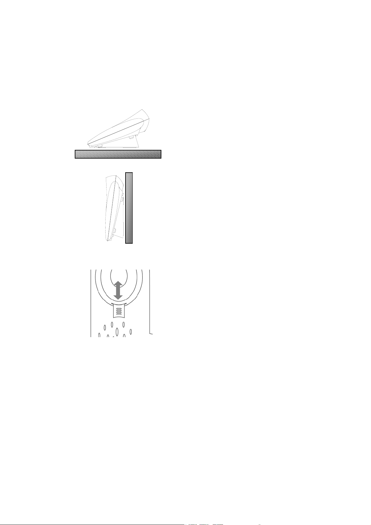
Place the Phone
Figure 4
Place the IPW2000 on the desk
When use it on the desk, user can use
the bracket for better view angle as
shown in figure 4.
Figure 5
Figure 6
Use the Headset
Place the IPW2000 on the wall
When use the phone on the wall, user
can use the wall hanger and tip as
shown in figure 5 and 6.
Pull up the conversion knob – Turn upside down – Insert
Insert the Headset into the SPK and MIC holes on the left side of the phone.
Warning : Please avoid the connection of MIC or SPK to another unfloating device
such as PC or amplifier which may result ground loop.
Tip : For TIA/EIA/IS-810 compliance, below headsets is recommended. In case of
using discommended headset, it may cause poor quality of voice and noise.
***Plantronics / TriStar H81***
4 IPW2000
Page 8
Set the Network Connection
This phone requires information : the following IP address, Subnet mask, Default
Gateway and DNS address.
There are two IP address setup mode :
+ DHCP (DHCP enables office network)
+ Manual IP (for static IP address)
After finishing hardware installation, remove and reconnect the power adapter to
the back of the Phone and immediately press the MENU button until “Input
Password” Menu appears.
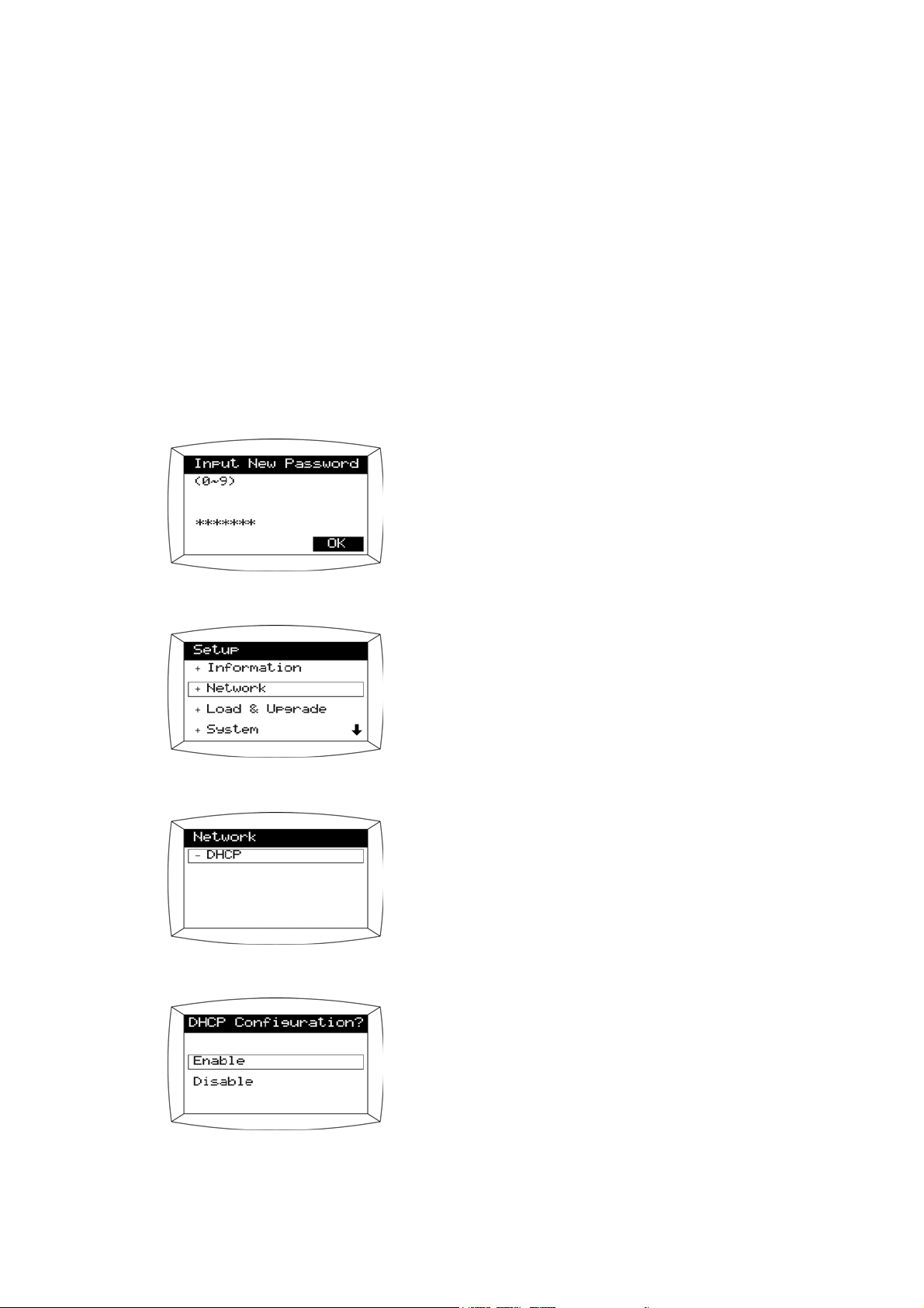
Set the DHCP Mode
On “Input Password” Menu,
Press the Administrator password
(Default :
0 5 1 7 0 9 4 3 )
Select +Network from the Setup Menu
Select –DHCP
In the DHCP Configuration field,
select Enable
5IPW2000
Page 9
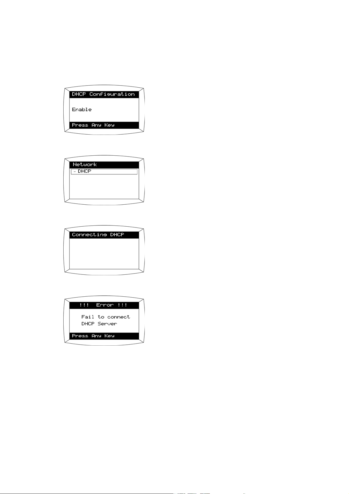
Setting the Network Connection
Press any key.
You can verify that DHCP enabled.
DHCP has been selected.
Exit Bootrom,
then you can see the left screen.
If there is some problem, you will see the
message shown on the left.
Otherwise phone will boot well.
Note : By using DHCP Mode, you can get the IP address, Net Mask, Default
Gateway and DNS address for networking.
6 IPW2000
Page 10

Set the Manual IP
Setting the Network Connection
Select + Network from the Setup Menu.
Select –DHCP
In the DHCP Configuration field,
select Disable.
Press any key.
You can see the screen on the left.
Then select – IP address.
7IPW2000
Page 11
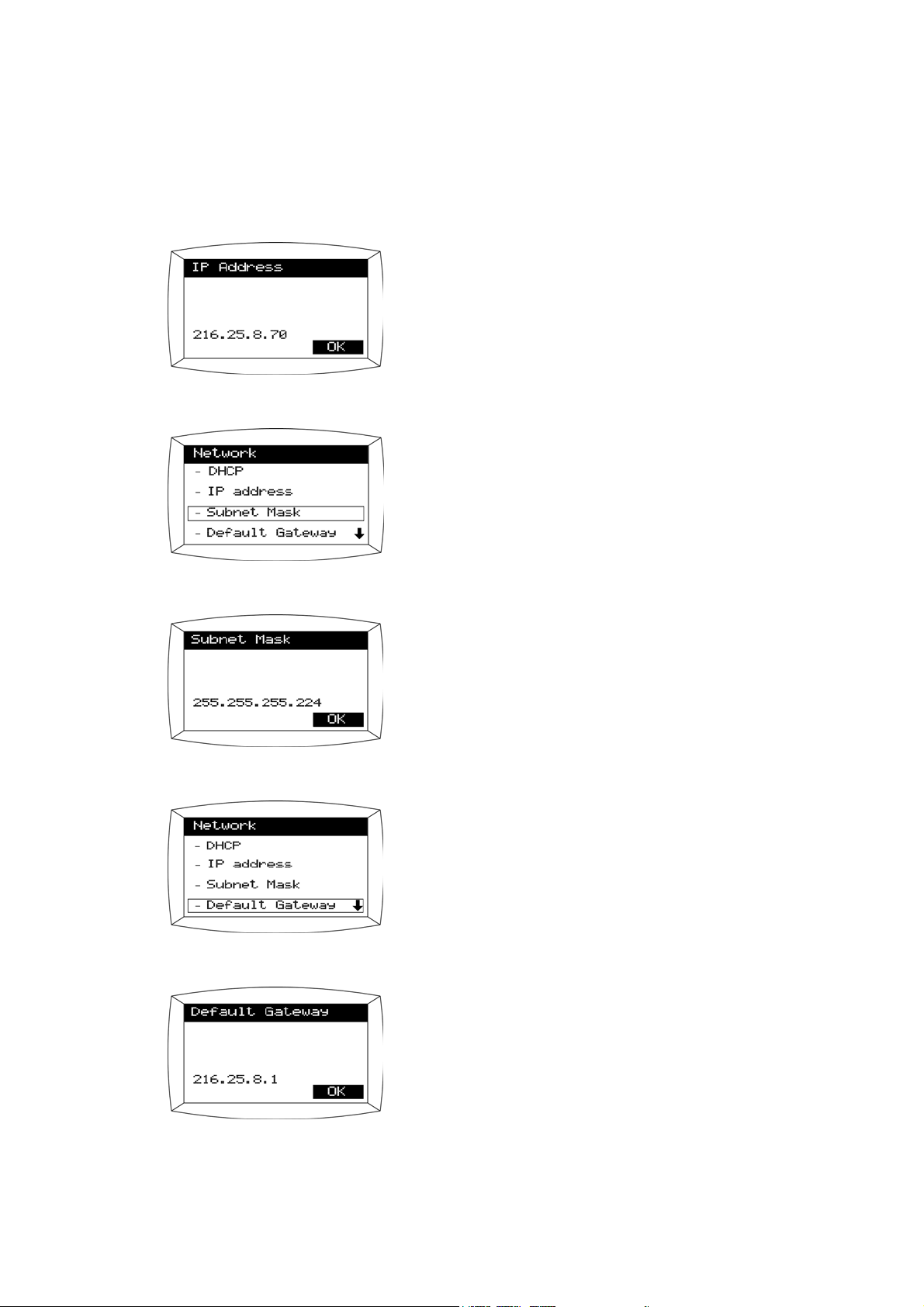
Setting the Network Connection
Enter your IP address and
Press the soft key next to OK.
You can see the screen.
Then select – Subnet Mask.
Enter your Subnet Mask and
Press the soft key next to OK.
You can see the screen.
Then select – Default Gateway
Enter your Default Gateway and
Press the soft key next to OK.
8 IPW2000
Page 12

Setting the Network Connection
You can see the screen.
Then select + DNS
There are three DNS entries.
Select – 1st DNS.
Enter your DNS IP address and
Press the soft key next to OK.
9IPW2000
Page 13

Set the Load Option
There are three options for loading application:
+ DHCP Server
+ TFTP Server
+ File System
Set the Load Option From DHCP
Select + Load & Upgrade.
Select + Load Option.
Select – DHCP server.
(If you want to choose DHCP server, you have
to have DHCP enabled in the network setting)
Press any key.
10 IPW2000
Page 14

Set the Load Option From TFTP
Setting the Load Option
Select – TFTP server.
Enter your – TFTP server if you have, then
Press the soft key next to OK.
Press any key.
11IPW2000
Page 15

Setting the Load Option
Set the Load Option From File System
Select – File System.
Press any key.
Note : File System option should be selected when there is no need to upgrade
the phone’s software through DHCP or TFTP. File System option prevents
the phone from upgrading software even if there is a power reset.
12 IPW2000
Page 16

Chang the Administrator Password
Use this function to change the local administrator password which is required to
gain access to all administration and diagnostic functions.
Select + System from the menu.
Select –Password.
Enter your old password, then
Enter your new password , and
Press the soft-key for OK
The factory default administrator password is
“
0 5 1 7 0 9 4 3 ”.
Retype your password and
Press the soft-key for OK
Press any key.
13IPW2000
Page 17

Factory Default and Clearing Password
Factory default can be used for the following reason:
1. When bootrom has a bug causing the phone to go down.
2. When a password is lost or corrupted.
To invoke the Factory Default Password, press “
with Off Hook before power on the phone.
You can see the factory default screen.
Select Yes to clear the Bootrom configuration
3”, “7”, “MUTE”, “F3/F10”key
Verify cleared Boot Conf..
Note : Factory Default impacts only the network information, load option and
password.
14 IPW2000
Page 18

Upgrade the Software
The following are the different ways to upgrade the software of the IPW2000 phone.
• TFTP auto upgrade
• Manual upgrade through TFTP server
• TFTP upgrade through power reset
TFTP Auto Upgrade
In order to upgrade the software using the TFTP auto upgrade feature, the following
preparation is required.
These requirements apply to manual TFTP upgrades as well.
1. Create a Trivial File Transfer Protocol (TFTP) directory path on a TFTP server
2. Copy the new IP phone software files to the TFTP directory created above.
3. Leave the TFTP server active in the IP network.
4. Leave the IP phones in the TFTP load option in the Bootrom menu.
Here is how auto TFTP software upgrade works:
When Load Option in the Bootrom menu is set to “TFTP”, “DHCP” the phone’s
application is upgraded periodically even if there is no power reset. The software
versions of the phone and TFTP server will be compared randomly within a certain
time window which is configurable by an administrator. The default window is from
1AM to 5 AM. If the software version in the TFTP server is the same as the
phone’s software, no upgrade will occur. If the phone’s software version is different
from the software in the TFTP server, the software upgrade will occur. There will
be a 5 minute warning message displayed on the LCD before the software upgrade
begins. Therefore the users are aware that the software upgrade is pending.
Users can go off hook and make a call or receive an incoming call while the
warning message is displayed on the LCD. However during the actual upgrade, the
phone is not operational. If there is an existing call, the upgrade will be postponed
until user goes on hook. Once the phone goes on hook the upgrade will occur
sometime within 5 minutes from the time the phone went on hook. In summary,
anytime the phone detects the off-hook, the upgrade will be delayed. However it is
advised that administrator of the IP phones notify the users in advance of the
upgrading schedule. The upgrade will last less than 1 minute. The administrator is
allowed to configure the upgrading schedule
15IPW2000
Page 19

Upgrade the Software
Manual upgrade through TFTP server
To invoke the Bootrom Menu.
Remove and reconnect the power on the back of the Phone and immediately
Press the MENU button until the Boot Rom Menu appears.
Select + Load & Upgrade from the menu.
Select + Load Option.
Select – TFTP server.
In the TFTP Server menu,
Enter the appropriate TFTP server’s address of
the PC where the TFTP service is installed, and
Press OK.
16 IPW2000
Page 20

Upgrade the software
Verify Load Option, then
Press any key.
Select + Upgrade Bootrom.
Select – TFTP server.
Verify TFTP server’s address, then
Press soft key beside OK.
After Bootrom downloading completed,
Press ENTER and
Select + Upgrade Program.
17IPW2000
Page 21

Upgrade the Software
Select – TFTP server.
Verify TFTP server’s address, then
Press soft key beside OK.
After Program downloading completed,
Press any key and
select Exit.
18 IPW2000
Page 22

Upgrade the software
TFTP Upgrade through Power Reset
The IPW2000 phone’s software can also be upgraded through a power reset. This
upgrade requires an active TFTP server which contains the target software to be
upgraded. If the software version in the TFTP server is the same as the one in the
phone, a power reset will not upgrade the software.
The Operation of the IP phone after the Software Upgrade
The IPW2000 phone operates normally after the software upgrade. It will maintain
the registration status and other network information so that the upgrade has
minimal effect on the phone’s operation.
The following is the information that is maintained even after the software has been
upgraded :
• Registration status with the gatekeeper, including the gatekeeper’s address
• The phone’s IP address, netmask, default gateway, and DNS address
• The TFTP address provisioned in the phone
• Alias information
•Password
• Call history
• Speed dial entry information
• Display information
19IPW2000
Page 23

Modify Software Parameters
Modify the user.ini File
There are a few parameters that can be adjusted by an administrator.
When an administrator wants to update the settings of IPW-2000 by updating those
parameters, the administrator must update the loadrun.ini file
[Provisioning]
CheckStart=3600
CheckVar=14400
[PBXConfig]
*UsingBBX=1
*ExtNumber = 9
*MaxInterNumLength=4
*LocalareaCode=02
; 3600sec x 1
; 3600sec x 4
Example ;
Upgrades should occur from 1AM till 5(1+4)AM
When Load Option in the Bootrom menu is set
to TFTP, the phone’s application is upgraded
automatically if the software versions of the
phone and TFTP server are different. The
upgrade occurs early in the morning
; Provide redial feature by editing the Caller ID
information that was received from Webswitch.
; 1 = Enable, 0 = Disable
; External incoming calls are edited for one
touch redial feature.
; When Caller ID number has more than 4 digits,
it’s considered as an external line.
; Area code
[Phone]
*AutoRegReqTimeout=1
*ReminderRing=0
*PauseInterval=1000
20 IPW2000
[Phone]
; Automatic Log On after the software upgrade.
(0= Disable, 1 = Enable)
; Reminder ring for a call on hold when user
goes on hook while using multi line.
(1 = Enable)
; 1000 = 1 second
Page 24

[MWI]
*MwiServer = 0.0.0.0
Modify Software Parameters
; When there is a message waiting for the alias,
message lamp will blink. Enter Webswitch
IP address
*MwiMode = 2
; 0 = disable
1 = Enable. The address entered for the MwiServer
above will be used to access the MwiServer.
2 = Enable. The address set for G.K address will be
used to access the MwiServer. Leave “MwiServer
=“ blank or as “0.0.0.0”. Otherwise, no Mwi service is
guaranteed.
Note : Mwi Server
The WebSwitch notifies by WAP if there is a voice message waiting for the phone,
or the forward feature is enabled for the phone. If the forwarding is enabled, you
will see the “F” icon on the upper right corner of the phone’s screen. If there is a
voice message, the phone’s message lamp will flicker.
In order to be able to receive such state information, the IPW2000 uses WAP to
register to the WebSwitch. If there is a voice mail came in, the WebSwitch sends
an indication message to the IPW2000.
In general, since the WebSwitch serves both as a Mwi Server and a Gatekeeper,
you will have to set MwiMode to 2. The MwiMode 1 is used for expandability
purpose when the Mwi Server is separate apart from the WebSwitch.
[CallCfg]
*DtmfsendSupChgMode=0
*OverlapSend=0
; En-block Mode and Overlap are the two ways
to send DTMF
DTMF setting can be done as follows
(En-block + Overlap send : Dialing on the idle
condition such as Redial, Programmable
function, Phone book support the En-block )
En-block Mode ;
DtmfsendSupChgMod=0 / Overlapsend=0
Overlap send
DtmfsendSupChgMod=0 / Overlapsend=1
En-block + Overlap send
DtmfsendSupChgMod=1 / Overlapsend=1
21IPW2000
Page 25

Modify Software Parameters
[H323]
*GateKeeper = 0.0.0.0
*FastConnect = 1
; Entering Webswitch IP address
(*Administrator can enter an IP address for a
group of Phones)
; Use of Fast Connect
( ‘1’ = Enable, ‘0’ = disable )
*H245Tunneling = 0
[Time]
*Server=130.155.98.1
*TimeOffset=10
[Media]
*JitBufSize=10
*G711FrameSize=30
; Supporting H.245 Tnunneling
( ‘1’ = Enable, ‘0’ = disable )
Enter the time server’s IP address.
User can also modify the time server address
from Phone Setting Menu.
; 1 in TimeOffset = 30minutes in GMT
TimeOffset = 24 [ GMT +00:00 ]
12 [ GMT –06:00 ]
42 [ GMT +09:00 ]
; Jiterbuffer Size, Default = 10
; For Provisioning G.711 Frame size
( Range : 10,20,30,40 default=20 )
*G729FrameSize=20
; For Provisioning G.729 Frame size
( Range : 10,20,30,40,50,60 default = 10 )
*G723FrameSize=60
; For Provisioning G.723 Frame size
( Range : 30,60,90 default = 30 )
*G711uPriority=1
*G711aPriority=2
*G729Priority=3
Each User group’ Codec priority can be
provision by remote management
*G729aPriority=4
*G729abPriority=5
*G723Priority=6
22 IPW2000
Page 26

[Service]
*ServiceMax = 8
*Name1 = FWB ON
*Name2 = FWB OFF
*Name3 = FWNA ON
*Name4 = FWNA OFF
*Name5 = DND ON
*Name6 = DND OFF
*Name7 = PICKUP
*Name8 = CALLBACK
*Number1 = *72
*Number2 = #72
*Number3 = *73
*Number4 = #73
*Number5 = *71777#
*Number6 = *70
*Number7 = *1
*Number8 = 5
Modify Software Parameters
Class keys are defined to be used with Switch,
Feature keys on the LCD can be used for speed
dialing
[System]
*AdminPw=051709431234
5678
To change the administrator password from
05170943 to12345678, the following line Should
be entered in user.ini file.
Then the IP Phone has to be upgraded with new
software Including the user.ini file. Administrator
also can change the administrator password an
each IP Phone.
Modify the loadrun.ini File
After changing the parameter in user.ini file, Administrator should change the date
Information in loadrun.ini file.
[options]
version=1.0.0
date=6/5/2002
The Software check the date in loadrun.ini file
before being upgrading.
date=6/5/2002 date=6/10/2002
23IPW2000
Page 27

Change the Voice Settings
Change the Voice Settings
Enter this menu to manage the voice quality of the phone. You can enter the Voice
menu from the System menu option in the phone.
Press the MENU button
On the MENU screen,
Select Phone Settings (Press ‘’ button)
On the phone settings menu screen,
Select Password (Press ‘’ button)
On the password menu screen
Enter your Administrator password
( Default =
Press the ENTER soft-key.
On the system menu screen
Select Voice (Press ‘’ button)
Press ‘’, ’’ button to move until you find the
proper value, then
Press the SAVE soft-key
0 5 1 7 0 9 4 3 ), then
24 IPW2000
Page 28

Product Specifications
CPU & Memory
Motorola ColdFire™ 40Mhz
16Mbit Flash Memory
32Mbit DRAM
AudioCodes™ DSP
Digital Signal Processing Features
G.711, G.723.1, G.729A
Selectable u-Law, A-Law of ITU-T G.711
G.168 25ms length adaptive echo canceller
Voice Activity Detector & Comport Noise Generator
DTMF generation
Digital Input/Output Gain Control
Handset Features
Volume Control for use by the hard of hearing
Hearing Aid Compatible Handset (FCC Part 68.112)
12ft extended length cord
TIA-810A Compliant
Weight is 220g
Headset Features
3.5mm mono Headset jack
RJ-11 4P4C Headset jack
Volume Control for use by the hard of hearing
Auto headset jack detect
Speaker Phone Features
Full duplex speaker phone
Volume control
Network
10/100Base-T Integrated 2 port Ethernet switch
802.1p/Q packet priority control
Port base VLAN
Up Link
Connector Type RJ-45
Type 10Base-T, 100Base-T
Power Over LAN supported Port ( IEEE 802.3 af )
Down Link
Connector Type RJ-45
Type 10Base-T, 100Base-T
25IPW2000
Page 29

Product Specifications
Display
Dot Graphic LCD
Resolution : 128 x 64
Viewing Area : 70.7 x 38.8 (mm)
Dot Size : 0.48 x 0.48 (mm)
Glass : FSTN
Viewing Angle : 6 O’clock direction 70deg
LED
Triple Color Message Indicate LED (Green/Yellow/Red)
Speaker Phone LED (Red)
Hold LED (Red)
Phone Line Indicate LED (Red)
Function Key Shift Indicate LED (Red)
Keys
12 Digit numeric Key
Phone Control Key
Speaker Phone, MUTE, Flash, Redial, Volume Up/Down
Programmable Function Key
7 of Programmable function keys can be used 14 Keys with Function Shift Key
Menu Key
Menu, Cancel, Cursor, Soft, Line1, Line2, Massage
Power
Operation Condition
Normal 5 Watt
Maximum 7 Watt
Operating Input Voltage : 16.5 ~ 60 VDC
Absolute Maximum Input Voltage : 63VDC
Adaptor
AC In : 100-240V 50/60Hz
DC Out : 18V 600mA
Certification : UL, CUL
Power Over LAN™ Compliant
24 or 48VDC Power via UTP Cable
Outward
Phone Size 223 x 218 x 66 (W x L x H, mm)
Phone weight 2.0 Kg
Color Metal Gray
26 IPW2000
Page 30

Reliability
Environment Specification
Operating Temp. 0 ~ +50℃
Storage Temp. -20 ~ +70℃
NEBS Office Vibration Test Compliant
Noise Specification
FCC Part 15 Class B
EN 55022
CISPR 22 Class B
IEC(EN) 61000-3-2
IEC(EN) 61000-3-3
Immunity Standards
IEC(EN) 61000-4-2 ESD
IEC(EN) 61000-4-3 Radiated RF
IEC(EN) 61000-4-4 EFT
IEC(EN) 61000-4-5 Surge
IEC(EN) 61000-4-6 Conducted RF
IEC(EN) 61000-4-11 Voltage Dips and Interruptions
Safety Standards
UL1950
Product Specifications
Certifications
FCC Part 15 Class B Listed
UL, CUL Listed pending (UL1950) ; File No. E218826
CE Mark
27IPW2000
Page 31

Glossary
Alias
In general, as a noun, an alias (pronounced AY-lee-uhs) is an alternate name for
someone or something. In literature, a "pen name" is an alias for the author's real
name.
CODEC
In this context, the term is an acronym for "coder/decoder."
This type of codec combines analog-to-digital conversion and digital-to-analog
conversion functions in a single chip.
The term codec is also an acronym that stands for "compression/decompression.
DHCP
DHCP (Dynamic Host Configuration Protocol) is a protocol that lets network
administrators manage centrally and automate the assignment of Internet Protocol
(IP) addresses in an organization's network. Using the Internet's set of protocol
(TCP/IP), each machine that can connect to the Internet needs a unique IP
address.
DNS
The domain name system (DNS) is the way that Internet domain name are located
and translated into Internet protocol addresses. A domain name is a meaningful and
easy-to-remember "handle" for an Internet address.
G.711
Audio codec for 3.1 Kbps bandwidth over 48,56, and 64 K bps channels
(normal telephony)
G.729
Audio codec for 3.1 Kbps bandwidth over 8 Kbps channels (adopted by the Frame
Relay Forum for voice over Frame Relay)
Gateway
A gateway is a network point that acts as an entrance to another network. In IP
Telephony, gateway connects PSTN and IP Network.
28 IPW2000
Page 32

Glossary
GK (Gatekeeper)
In an H.323 multimedia network, gatekeepers perform critical control, administration
and management functions needed to maintain the integrity of corporate local and
wide area networks. In particular, the gatekeeper is the industry standard
mechanism for Call control and call routing, basic telephony services such as
directory services and PBX functions (e.g. call transfer, call forwarding).
H.323
A standard approved by the International Telecommunication Union (ITU) that
defines how audiovisual conferencing data is transmitted across networks. In theory,
H.323 should enable users to participate in the same conference even though they
are using different videoconferencing applications. Although most
Videoconferencing vendors have announced that their products will conform to
H.323, it's too early to say whether such adherence will actually result in
interoperability.
IP Telephony
IP telephony (Internet Protocol telephony) is a general term for the technologies that
use the Internet Protocol's Packet-switched connections to exchange voice, fax, and
other forms of information that have traditionally been carried over the dedicated
circuit-switched connections of the public switched telephone network.
Jitter
Jitter is the deviation in or displacement of some aspect of the pulses in a highfrequency digital signal. As the name suggests, jitter can be thought of as shaky
pulses. The deviation can be in terms of amplitude, phase timing, or the width of the
signal pulse.
LAN
A local area network (LAN) is a group of computers and associated devices that
share a common communications line and typically share the resources of a single
processor or server within a small geographic area (for example, within an office
building).
MAC address
On a local area network (LAN) or other network, the MAC (Media Access Control)
address is your computer's unique hardware number. (On an Ethernet LAN, it's the
same as your Ethernet address.) When you're connected to the Internet from your
computer (or host as the Internet protocol thinks of it), a correspondence table
relates your IP address to your computer's physical (MAC) address on the LAN.
29IPW2000
Page 33

Glossary
Q o S
Measure of performance for a transmission system that reflects its transmission
quality and service availability.
UTP
Unshielded twisted pair is the most common kind of copper telephone wiring.
Twisted pair is the ordinary copper wire that connects home and many business
computers to the telephone company.
VoIP
VoIP (voice over IP - that is, voice delivered using the Internet Protocol) is a term
used in IP Telephony for a set of facilities for managing the delivery of voice
information using the Internet Protocol(IP). In general, this means sending voice
information in digital form in discrete Packet rather than in the traditional circuitcommitted protocols of the public switched telephone network.
30 IPW2000
Page 34

Asia Pacific
Ericsson Enterprise
Jalan SS7/19, Kelana Jaya
47301 Petaling Jaya
Selangor
MALAYSIA
Phone: +60 3 7808 7000
enterprise.asiapacific@ebc.ericsson.se
Nordic
Ericsson Enterprise
LM Ericssons vag 8
126 25 Stockholm
SWEDEN
Phone: +46 8 579 18 000
enterprise.nordic@ebc.ericsson.se
Produced in November 2002
EN/LZT 108 6349
Ericsson Enterprise AB 2002
Americas
Ericsson Enterprise
6300 Legacy Drive
Plano, TX-75024-3607
USA
Phone: +1 972-583-5000
enterprise.latinamerica@ebc.ericsson.se
Western Europe
Ericsson Enterprise
Avenue du Bourget 44
Bourgetlaan
1130 Brussels
BELGIUM
Phone: +32 2 745 12 11
enterprise.westerneurope@ebc.ericsson.se
Central and Eastern Europe
Middle East, Africa
Ericsson Enterprise
Pottendorferstr. 25-27
A-1121 Vienna
AUSTRIA
Phone: +43 1 81 10 00
enterprise.centraleurope@ebc.ericsson.se
 Loading...