

Page 1
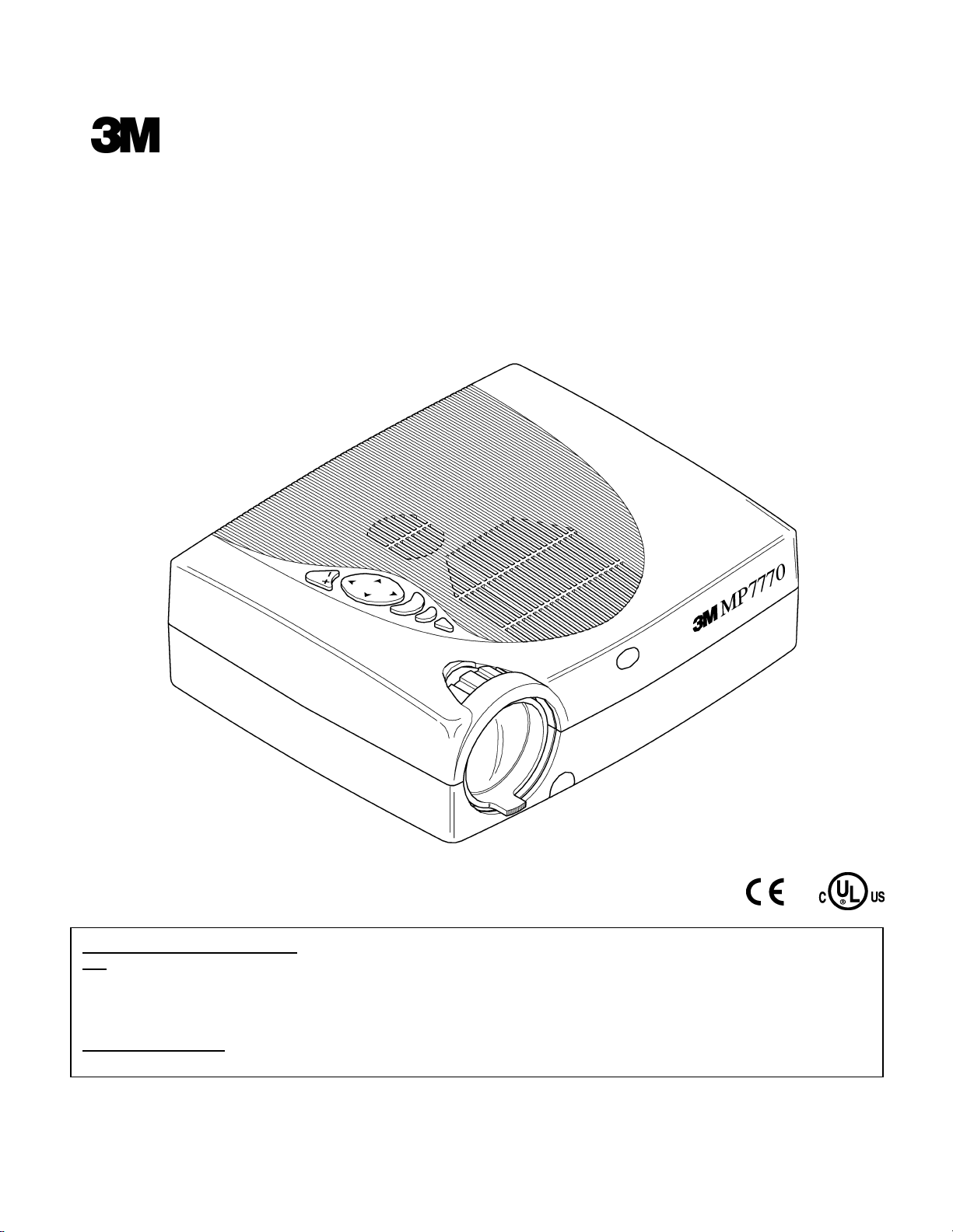
MP7770 Multimedia Projector
Service Manual
3M Visual Systems Division EPS Service Documentation
6801 River Place Boulev
ard Copyright © 2002, 3M IPC. All Rights Reserved.
Austin, T
exas 78726-9000 78-6970-8985-8
Warranty and Limited Remedy. This product will be free from defects in material and manufacture for a period o
f
two years from the date of purchase. 3M MAKES NO OTHER WARRANTIES INCLUDING, BUT NOT LIMITED TO, ANY
IMPLIED WARRANTY OF MERCHANTABILITY OR FITNESS FOR A PARTICULAR PURPOSE. If this product is defective
within the warranty period stated above, your exclusive remedy shall be, at 3M’s option, to replace or repair the 3M product o
r
refund the purchase price of the 3M product. ______________________________________________________________
_
Limitation of Liability
. Except where prohibited by law, 3M will not be liable for any loss or damage arising from this
3M product, whether direct, indirect, special, incidental or consequential regardless of the legal theory asserted.
Page 2

MP7770 Table of Contents
2002, 3M IPC. i
SECTION 1. MACHINE OVERVIEW
1-1 Overview.................................................................................................................................................1-1
1-2 Machine Identification............................................................................................................................1-1
1-3 Cleaning..................................................................................................................................................1-1
1-4 Safety......................................................................................................................................................1-2
1-5 Specifications..........................................................................................................................................1-3
SECTION 2. DISASSEMBLY/REASSEMBLY
2-1 Overview.................................................................................................................................................2-1
2-2 Required Tools........................................................................................................................................2-1
2-
3
Steps for Removing Projector Components............................................................................................2-1
2-3-1 Remove Bottom Cover...........................................................................................................2-2
2-3-2 Remove Top Cover.................................................................................................................2-4
2-3-3 Remove Interface Board Plate................................................................................................2-5
2-3-4 Remove Interface Board.........................................................................................................2-6
2-3-5 Remove DMD Kit...................................................................................................................2-7
2-3-6 Remove Main Fan...................................................................................................................2-8
2-3-7 Remove Power Supply and Flyback Converter......................................................................2-9
2-3-8 Remove Video Board .............................................................................................................2-10
SECTION 3. TROUBLESHOOTING
3-1 Troubleshooting Flowcharts...................................................................................................................3-1
3-1-1 Firmware Update.........................................................................................................................3-1
3-1-
2
Fan Cooling System Check.........................................................................................................3-2
3-1-3 Sound Check................................................................................................................................3-3
3-1-4 Video Check................................................................................................................................3-4
3-1-
5
No Image, Start-Up Screen OK...................................................................................................3-5
3-1-
6
No Image, No Start-Up Screen....................................................................................................3-6
3-1-
7
Lamp Does Not Work..................................................................................................................3-7
3-1-8 No Function.................................................................................................................................3-8
3-1-
9
Switch OFF In Hot Condition.....................................................................................................3-9
Page 3

MP7770 Table of Contents
2002, 3M IPC. ii
SECTI
ON 4. THEORY AND DIAGRAMS
4-1 Theory of Operation..............................................................................................................................4-1
4-2 Wiring Diagrams...................................................................................................................................4-2
4-2-1 Wire Routing ...............................................................................................................................4-2
4-2-
2
Wire Routing Parts Identification................................................................................................4-3
4-2-3 Component Connections .............................................................................................................4-4
4-3 Cabling and Cable Connectors..............................................................................................................4-5
4-3-
1
PC and MAC Cabling..................................................................................................................4-5
4-3-2 PC Cabling...................................................................................................................................4-6
4-3-
3
Cabling Parts Identification.........................................................................................................4-7
4-3-4 Cable Connectors.........................................................................................................................4-8
4-4 Functional Diagrams .............................................................................................................................4-11
4-4-1 Component Layout......................................................................................................................4-11
4-4-
2
Component Pin Connections.......................................................................................................4-12
Page 4

3M™ Multimedia Projector MP7770 Machine Overview
2002, 3M IPC. 1-1
1. Machine Overview
1-1. Overview
Make advanced adjustments to this projector in a clean environment with minimal dust and positive pressure.
This section provides the advanced adjustment procedures needed to maintain a high quality projection image.
There is a specific order that adjustments are to be made and specific tools needed to complete each adjustment.
Important
Only complete advanced adjustments to a projector
when the machine settings fall outside of the
allowable tolerances for that adjustment or when
instructed to do so by another procedure.
1-2. Machine Identification
To avoid incorrect adjustments or part replacements, verify the model and version of the projector prior to
making any adjustments or repairs.
Different versions have unique adjustment requirements. The serial number for the projector is located on the
machine identification label on the bottom of the projector.
1-3. Cleaning
When cleaning any components of the light engine, extreme care must be taken. Use only soft, dry, clean,
Chamois Swabs (Part number 78-8118-3302-5) to clean reflective surfaces. No chemicals should be used on any
surface.
Important
Use extreme care when cleaning any optics
device. Special coatings can be scratched very
easily.
Page 5
3M™ Multimedia Projector MP7770 Machine Overview
2002, 3M IPC. 1-2
1-4. Safety
Read and understand all safety procedures before making any repairs to the MP7770 Multimedia Projector.
Note
When
any work is being carried out on the device, the mains cable must be disconnected from the mains supply.
Only service personnel may carry out service work. For any repair regional and corresponding national regulations
are to be followed.
Up to 30.000 V may be incurred when the lamp is ignited; lethal hazard!
An isolation transformer has to be used during any service to avoid possible shock hazard, because of not
protected live parts on opened device
Eye damage may result from directly viewing into the lamp
The lamp is very high temperature and high pressure during operation. Cool down, before opening lamp cover and
handling. Wear special protective glasses. Never switch “ON“ without the lamp (high voltage an lamp wiring, 25-35
kV).
1
1. Service and repairs may only be carried
out by well-trained personnel. Regional
and national regulations concerning the
execution of repairs have to be observed.
2.
O
perate the unit with mounted protection
plate only (item 1) for protection against
possible lamp explosion.
3.Put the unit on an antistatic and hard-to inflame support only.
4.
Cables around power supply and lamp
are under high tension.
5. Take care not to touch the lamp base
when replacing the lamp. It is extremely
hot and may cause burns to the skin.
Allow the unit at least 5 minutes to cool
down.
Page 6
3M™ Multimedia Projector MP7770 Machine Overview
2002, 3M IPC. 1-3
1-5. Specifications
4,5
x
3,4
1,5
x
1,13
2
x
1,5
2,5
x
1,88
3
x
2,25
3,5
x
2,63
4
x
3
H%
B
x
H
36mm tele
6,0
L
(m)
28mmwide
(m)
4,0
3,0
2,0
5,4
4,7
3,4
3,3
2,7
2,6
2,3
1,9
1,5
1,1
~
100 - 240V AC
200 - 240V AC
50 - 63 Hz
35 C max
10 C min
3,0 Kg
95 F max
50 F min
1024
768
80
40
215
257
H
B
L
Page 7
3M™ Multimedia Projector MP7770 Disassembly/Reassembly
2002, 3M IPC. 2-1
2. Disassembly/Reassembly
2-1. Overview
Disassembly and reassembly of the MP7770 is done using the reference photographs and the step-by-step
procedures that follow. Many component disassembly steps build upon previous disassembly steps. Refer to the
previous disassembly steps as needed.
For general machine operation instructions including air filter or lamp replacement, refer to the Operator’s
Guide.
To avoid electrical shocks, unplug projector power cord before performing any
maintenance to electrical components.
To avoid burns to fingers, allow projector lamp and internal projector components to
cool off prior to lamp removal or disassembly.
2-2. Required Tools
An entire disassembly and reassembly can be completed with the following tools:
•= #3 T
orx driver
•= #10 Torx driver
•= #15 Torx driver
•= 5 mm nut driver
•= 5.5 mm nut driver
•= Wire cutter
2-3. Steps for Removing Projector Components
Removal topics include:
•= B
ottom Cover
•= Top Cover
•= Interface Board Plate
•= Interface Board
•= DMD Kit
•= Main Fan
•= Power Supply and Flyback Converter
•= Video Board
√√√√ Note
If performing a complete disassembly, record lamp time.
!
Caution
!
WARNING
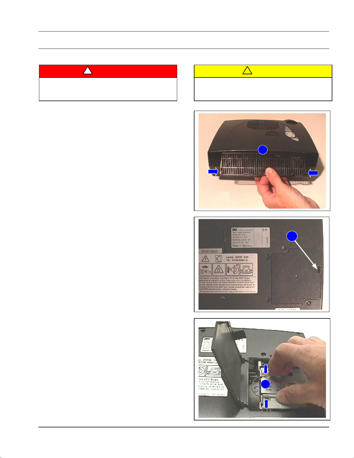
Page 8
3M™ Multimedia Projector MP7770 Disassembly/Reassembly
2002, 3M IPC. 2-2
1
2
3
2-3-1. Remove Bottom Cover
To avoid electrical shocks, unplug projector
power cord before performing any maintenance to
electrical components.
To avoid burns to fingers, allow projector lamp
and internal projector components to cool off prior
to lamp removal or disassembly.
1.
Press locking tabs and lift upward to remove
air filter
cover.
2.
Press locking tab and open lamp
door.
3.
Press both sides of wire clip/handle to disengag
e.
!
Caution
!
WARNING
Page 9
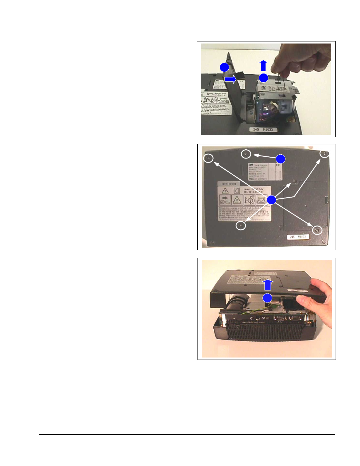
3M™ Multimedia Projector MP7770 Disassembly/Reassembly
2002, 3M IPC. 2-3
4
5
6
7
8
4. Using steady pressure, pull upward on clip/handle to
rem
ove lamp m
odule.
5.
Close lamp
door.
6.
Use a #10 torx driver and remove five
(5) screws on
bottom
of proj
ector.
7.
Remove one (1) longer screw by adjustme
nt foot.
8.
Carefully lift bottom cover off of projector body
.
9.
Reassemble in reve
rse order.
Page 10
3M™ Multimedia Projector MP7770 Disassembly/Reassembly
2002, 3M IPC. 2-4
2
1
3
4
2-3-2. Remove Top Cover
To avoid electrical shocks, unplug projector
power cord before performing any maintenance to
electrical components.
To avoid burns to fingers, allow projector lamp
and internal projector components to cool off prior
to lamp removal or disassembly.
R
emove bottom cover.
1.
Use a #10 torx driver and remove
three (3) screws
securing
top cove
r.
2.
Turn the projector over and carefully
lift upward on
the top cov
er to separate it from the proj
ector
components.
√√√√ Note
Attached to the top cover is a ribbon cable and wire
connector that must be disconnected.
3. Disconnect ribbon cable.
4. Disconnect wire connector.
5.
Remove top cove
r.
6.
Reassemble in reverse order.
!
Caution
!
WARNING
Page 11
3M™ Multimedia Projector MP7770 Disassembly/Reassembly
2002, 3M IPC. 2-5
1
2
3
2-3-3. Remove Interface Board Plate
To avoid electrical shocks, unplug projector power
cord before performing any maintenance to
electrical components.
To avoid burns to fingers, allow projector lamp
and internal projector components to cool off prior
to lamp removal or disassembly.
Rem
ove top and bottom covers.
1.
Use a 5mm nut driver and remove
four (4) nuts
securing plate.
2. Disconnect wire connector.
3. Rem
ove
plate.
4.
Reassemble in reve
rse order.
!
Caution
!
WARNING
Page 12
3M™ Multimedia Projector MP7770 Disassembly/Reassembly
2002, 3M IPC. 2-6
1
3
2
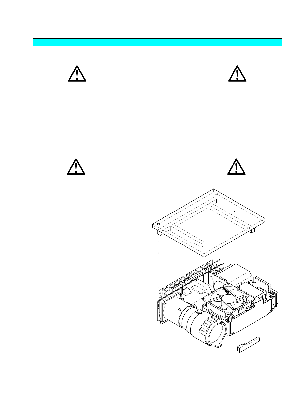
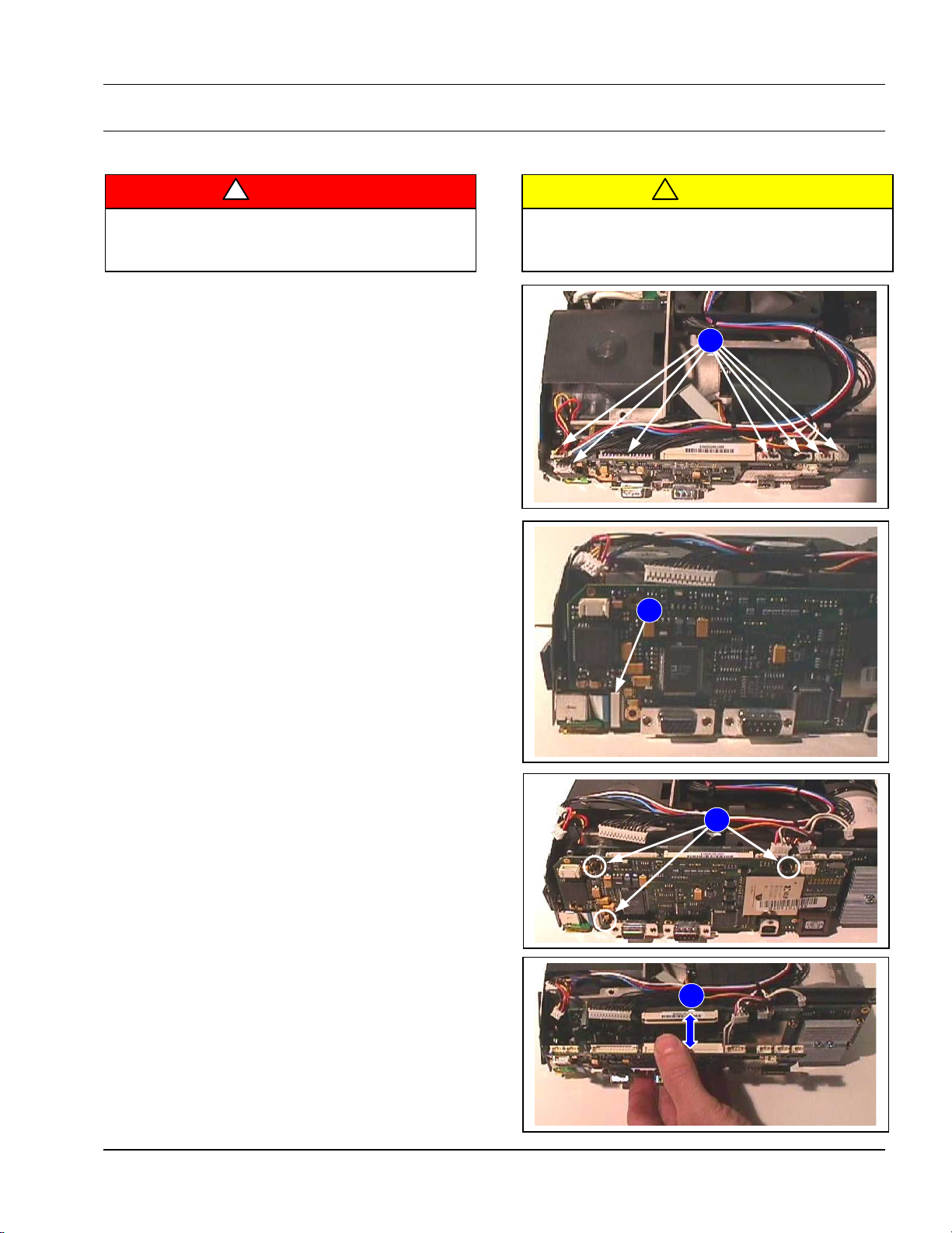
2-3-4. Remove Interface Board
To avoid electrical shocks, unplug projector
power cord before performing any maintenance to
electrical components.
To avoid burns to fingers, allow projector lamp
and internal projector components to cool off prior
to lamp removal or disassembly.
R
emove top cover, bottom cover and interface board
plate.
1.
Disconnect seve
n (7) wire connectors.
2. Disconnect ribbon cable.
3.
Use #10 torx driver to remove
three (3) screws
securing board.
4.
Carefully
pull at top of board to separate the white pin
connector.
5.
Reassemble in reve
rse order.
!
Caution
!
WARNING
4
Page 13
3M™ Multimedia Projector MP7770 Disassembly/Reassembly
2002, 3M IPC. 2-7
1
5
6
3
2
4
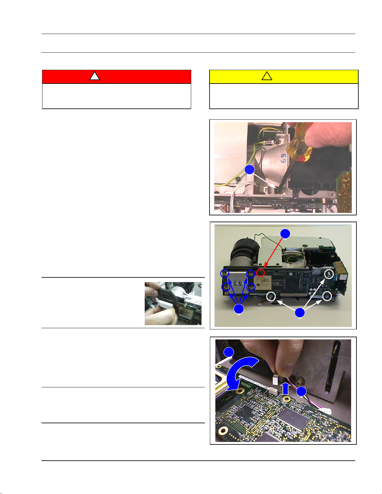
2-3-5. Remove DMD Kit
To avoid electrical shocks, unplug projector
power cord before performing any maintenance to
electrical components.
To avoid burns to fingers, allow projector lamp
and internal projector components to cool off prior
to lamp removal or disassembly.
R
emove top cover, bottom cover, interface board plate
and interface board.
1.
Use #10 torx driver to loosen one (1) screw securing
the thermo
stat.
2.
Use a 5.5mm nut driver to remove
three (3) nuts.
3.
Use a #3 torx driver and remove
four (4) nuts.
4.
Use a #10 torx driver and remove
one (1) screw.
√√√√ Note
The DLP-Kit replacement board will
come with a protective spacer.
Remove spacer and install it on
all warranty returns, to prevent
damage during shipment.
5.
Carefully separate DMD board and lay
it down on the
bench top.
6. Disconnect one (1) ribbon cable connector.
√√√√ Note
Notice the printing on the ribbon cable and during
reassembly, install the ribbon cable same side up.
Reversing the cable will cause poor image quality.
7. Reassemble in reverse order.
!
Caution
!
WARNING
Page 14
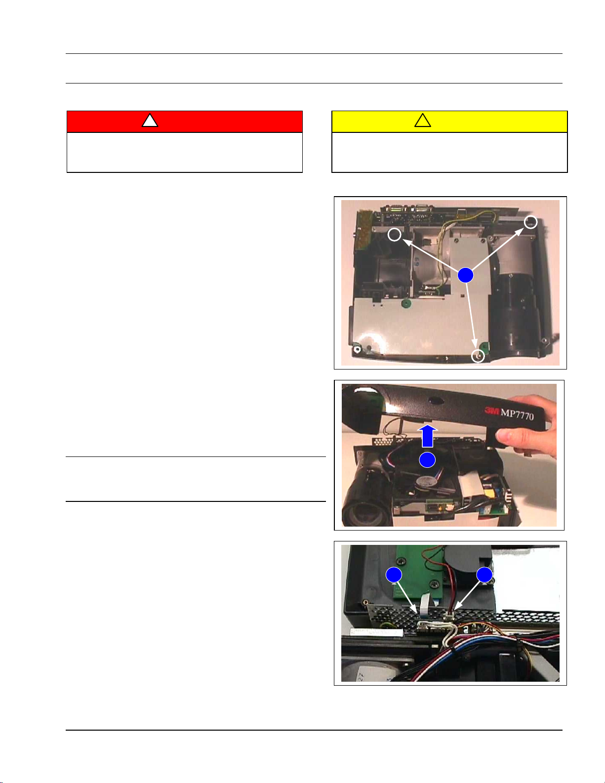
3M™ Multimedia Projector MP7770 Disassembly/Reassembly
2002, 3M IPC. 2-8
1
2
5
4
3
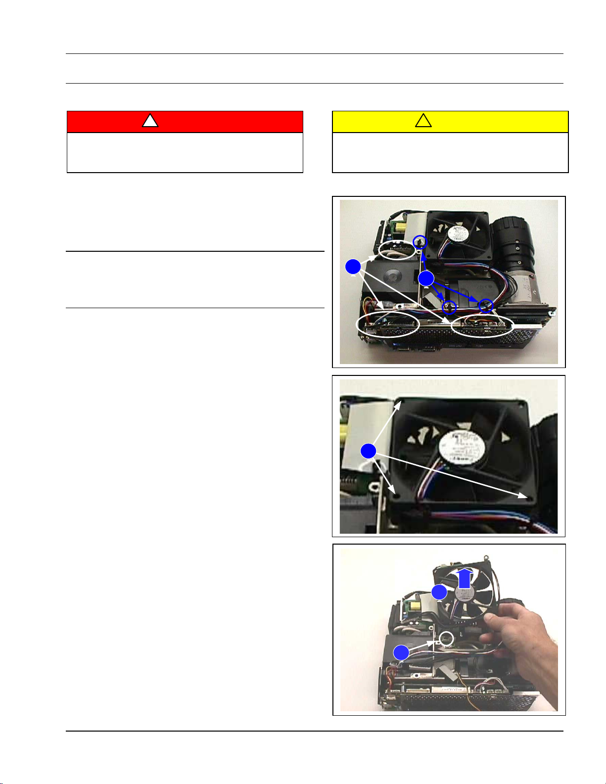
2-3-6. Remove Main Fan
To avoid electrical shocks, unplug projector
power cord before performing any maintenance to
electrical components.
To avoid burns to fingers, allow projector lamp
and internal projector components to cool off prior
to lamp removal or disassembly.
Rem
ove top and bottom covers.
1.
Disconnect all wire connectors from
fan.
√√√√ Note
It is very important to repeat the exact wire paths during
reassembly. A different wire path can cause excess noise
and reduce image quality.
2.
Cut three (3) wire ties securing wi
res.
3.
Use a #10 torx driver to remove
three (3) screws
securing fan.
4.
Slide the fan assembly forward to access one (1) wi
re
connector located underneath. Disconnect wire
connector.
5.
Lift upward to remove the fan assembly
.
6.
Reassemble in reve
rse order.
!
Caution
!
WARNING
Page 15

3M™ Multimedia Projector MP7770 Disassembly/Reassembly
2002, 3M IPC. 2-9
1
2
3
4
2-3-7. Remove Power Supply and Flyback Converter
To avoid electrical shocks, unplug projector
power cord before performing any maintenance to
electrical components.
To avoid burns to fingers, allow projector lamp
and internal projector components to cool off prior
to lamp removal or disassembly.
1. Cut one (1) wire tie.
2. Disconnect wire connector.
3.
Remove one (1) screw securing power supply
and
converter.
4.
Remove
one (1) wire connector.
5.
Reassemble in reve
rse order.
!
Caution
!
WARNING
Page 16

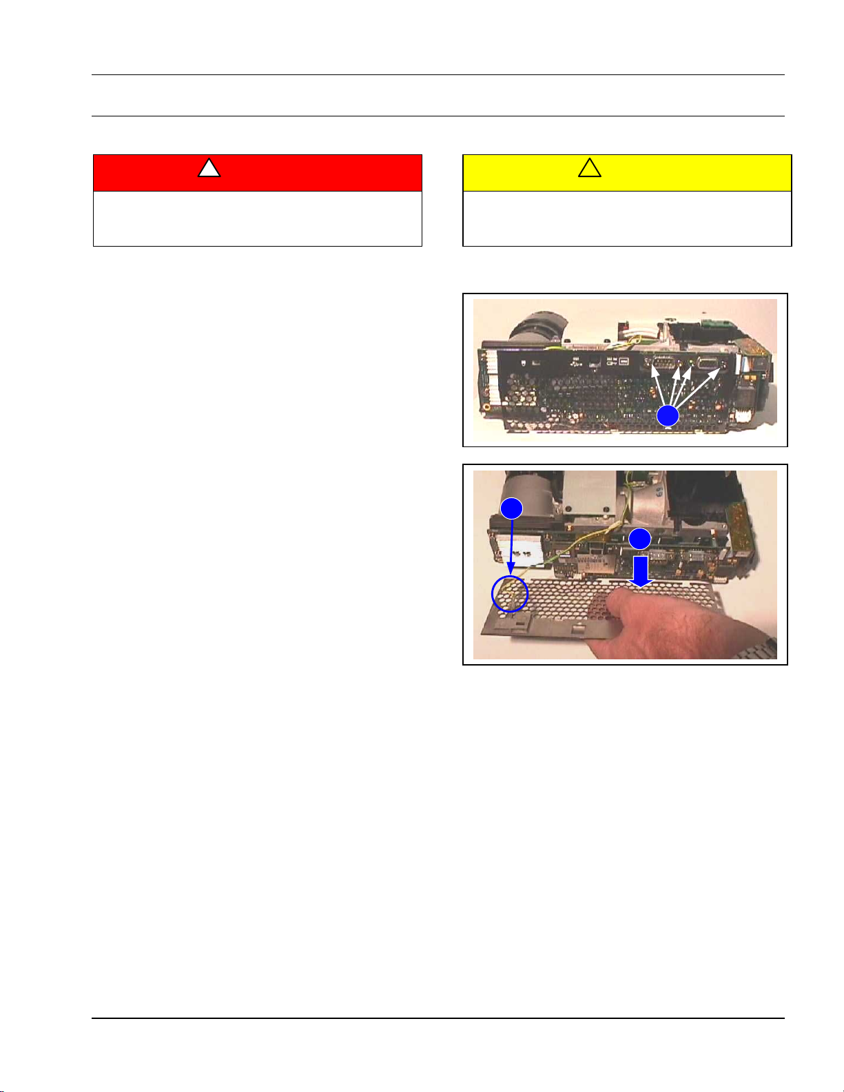
3M™ Multimedia Projector MP7770 Disassembly/Reassembly
2002, 3M IPC. 2-10
1
2
3
2-3-8. Remove Video Board
To avoid electrical shocks, unplug projector
power cord before performing any maintenance to
electrical components.
To avoid burns to fingers, allow projector lamp
and internal projector components to cool off prior
to lamp removal or disassembly.
1.
Remove one (1) screw securing vi
deo board and
plastic cov
er inside vi
deo board.
2.
Separate video board and remove plastic cove
r.
√√√√ Note
During reassembly, the plastic video cover must line up
with the screw hole for the video board. See Step #1.
3.
Remove
ribbon cable.
4.
Reassemble in reve
rse order.
!
Caution
!
WARNING
Page 17

3M Multimedia Projector MP7770 Troubleshooting
2002, 3M IPC. 3-1
3. Troubleshooting
T
his section provides message flowcharts to aid in troubleshooting the 3M MP7770 Multimedia Projector.
3-1. Troubleshooting Flowcharts
3-1-1. Firmware Update
Factory Reset
Switch on
unit in Standby
Message:
"Parameter Factory Settings
Restored"
appears
PressStandby
Hold Menü
and Enter
pressed (appr. 10sec)
C6/S10
C6/S1
C6/S2;S9
Press Menü
and Enter
simultaneou s
C6/S1
C6/S2;S9
Page 18

3M Multimedia Projector MP7770 Troubleshooting
2002, 3M IPC. 3-2
3-1-2. Fan Cooling System Check
MainFan
working?
CartridgeFan
working?
Lamp Fan
working?
Check
PIN1:+5V
PIN2:-5V
C1/J11
Check
PIN1:+4V
PIN2:GND
C1/J9
Check other fans
Change Main Fan
5b/12
ChangeLamp Fan
5a/13
ChangeCartridge Fan
7/9
NO
NO NO
YES
YES
YES
YES
YES
YES
NO
NO
No
+5V
Check
PIN3
C1/J11
-5V
YES
NO
Check
PIN3..........
700Hz 7V pp
C1/J9
YES
NO
No
Check
PIN3..........
300Hz 5V pp
C1/J7
Check
PIN1:+3V
PIN2:-5V
C1/J7
Projector switch off after approx. 5sec.
Standby blinks red
/
yellow
C6/S10
ChangeInterface
5a/260
Check Flyback output
Voltages
ChangeFlyback-Converter
6/10
YES
NO
YES
Page 19

3M Multimedia Projector MP7770 Troubleshooting
2002, 3M IPC. 3-3
3-1-3. Sound Check
No sound?
Change
Connectionboard
5a/11
Check Audio Signal
C1/J13
Check Audio Signal
C1/J6
Change Interfaceboard
5a/260
Change Speaker
3/40
YES
YES
NO
NO
Page 20

3M Multimedia Projector MP7770 Troubleshooting
2002, 3M IPC. 3-4
3-1-4. Video Check
No Video
Data mode OK
Change
Connectionboard
5a/11
Check Video Signal
Change Interfaceboard
5a/260
good
Not
good
C1/J4
Page 21

3M Multimedia Projector MP7770 Troubleshooting
2002, 3M IPC. 3-5
3-1-5. No Image, Start-Up Screen OK
No Image
only Start up screen
Check internal Test
pattern
Change Interfaceboard
5a/260
good
Not
good
Bad connection
Interface-Engine
Clean
C1/J1
Change DLP-Kit
5b/440
NO
YES
Page 22

3M Multimedia Projector MP7770 Troubleshooting
2002, 3M IPC. 3-6
3-1-6. No Image, No Start-Up Screen
Lampignites,
-but dark image
-no start up screen
NO
YES
Check CW index
PIN3
C1/J14
Change Engine
5b/400
Change Interfaceboard
5a/260
Check Voltage
CW index
PIN5: +1.5V
C1/J14
Change Interfaceboard
5a/260
YES
NO
Check Flyback output
Voltages
C2/J2
Change Flyback-Converter
6/10
NO
YES
Page 23

3M Multimedia Projector MP7770 Troubleshooting
2002, 3M IPC. 3-7
3-1-7. Lamp Does Not Work
Lamp doesn´t ignite
Check Lamp visually
Is H-Level at
LAMPEN
PIN4
C1/J19
Colorwheel working
Change Engine
5b/400
Change Interfaceboard
5a/260
NO
NO
YES
YES
Change Lamp Ballast
6/70
Page 24

3M Multimedia Projector MP7770 Troubleshooting
2002, 3M IPC. 3-8
3-1-8. No Function
Projector doesn`t switch
on
Change Interfaceboard
5a/260
Check 390V DC
C2/J3
Check Lamp Door
4/20
Check Mains input
8a/10
Check DC-Voltage
C1/J19
Change Flyback-
Converter
6/10
YES
YES
NO
NO
Change Lamp Ballast
6/70
Page 25

3M Multimedia Projector MP7770 Troubleshooting
2002, 3M IPC. 3-9
3-1-9. Switch OFF In Hot Condition
CT8
Projector switch off in
hot condition
Projector goes off completes
-Fan run continuously
-switch in Standby again after cooling down
-Overtemperatur-MainThermo switch
Projector goes into Standby
-Fan run continuously
-Overtemperatur-Sensorboard
Projector goes in Standby
-Fan run continuously
- after cooling down unit can be started again
-Overtemperatur-Thermo switch Lamp Ballast
Clean Air filter
2/70
Page 26

3M Multimedia Projector MP7770 Theory and Diagrams
2002, 3M IPC. 4-1
4. Theory and Diagrams
T
his section provides the following theory and diagram information for this product:
•= Theory of Operation
•= Wiring Diagrams
•= Cabling and Cable Connectors
•= Functional Diagrams
4-1. Theory of Operation
LENS
PRISM
COLORWHEEL
INTEGRATER
DMD
LAMP
IR-FILTER
Page 27

3M Multimedia Projector MP7770 Theory and Diagrams
2002, 3M IPC. 4-2
4-2. Wiring Diagrams
4-2-1. Wire Routing
1 2 3
4
5
6
7
8
9
10
11
12
13
14
16
25
18
20
20
22
21
23
24
17
26
27
28
29
30
31
31
black
yellow
blue
red
green/yellow
white
F3,15A
NOTE: Part numbers and
descriptions are on the
following page.
Page 28

3M Multimedia Projector MP7770 Theory and Diagrams
2002, 3M IPC. 4-3
4-2-2. Wire Routing Parts Identification
Item Liesegang 3M Serial
Nu
mber Description Part Number Part Number Number
1 Cable 270 green/yellow EF 0246099230 78-8118-3676-
2
10001-
2 PWB Panel BG 0245066019 78-8118-8518-
1
10001-
3 Speaker BG 0245011508 78-8118-8515-
7
10001-
4 Cable Video Board EK 0245099050 78-8118-8580-
1
10001 5 Cable 360 4pol. compl. BG 0245099088 78-8118-8581-9 10001 6 Cable Keyboard EK 0245099060 78-8118-8582-
7
10001 7 PWB Interfac
e **
BG 0275044219 not available 10001-10210
7 PWB Interfac
e **
BG 0275044319 78-8118-8737-
7
10001-
8 EPROM 4M BG 0275099910 78-8118-8736-
9
10001 9 Fan Cardrige EK 0245022200 78-8118-8536-
3
10001 10 Fan Main BG 0245022219 78-8118-8541-
3
10001-
11 Cable 360 14pol. compl. BG 0245099039 78-8118-8583-
5
10001-
12 Cable 360 3pol. compl. BG 0245099038 78-8118-8584-
3
10001-
13 Fan Lamp EK 0275022230 78-8118-8747-
6
10001-
14 Thermostat EK 0245099108 78-8118-8559-
5
10001-
16 XG
A DMD Kit *,**
BG 0245077019 78-8118-8738-
5
10001-
17 PWB IR-Receiver BG 0245066517 78-8118-8750-
0
10001-
18 PWB Video BG 0245088119 78-8118-8540-
5
10001 20 Washer, tooth A4,3 DT 0050679703 not available 10001 21 Cable 155 green/yellow EF 0245099250 78-8118-8586-
8
10001 22 Screw TORX M 4x6 StZn, black DT 0040190180 not available 10001 23 Engine complete (without lamp
and DMD) **
BG 0275022505 78-8118-8458-0 10001-
24 Lamp-Kit 200W BG 0275022008 78-6969-9296-
1
10001-
25 PWB Thermostat BG 0245066319 78-8118-8558-
7
10001 26 Power Supply
**
BG 0275099215 78-8118-8740-
1
10001-
27 Cable 120 2pol. compl. BG 0245099148 78-8118-8587-
6
10001-
28 Fuse F3,15A EK 0060560620 78-8118-8579-
3
10001-
29 Cable 125 6pol. compl. BG 0245099098 78-8118-8588-
4
10001-
30 PWB Flyback-Converter ** BG 0245099509 78-8118-8739-
3
10001 31 Tie Wrap 102x2.5 EK 0060760770 not available 10001-
Page 29

3M Multimedia Projector MP7770 Theory and Diagrams
2002, 3M IPC. 4-4
4-2-3. Component Connections
Flyback
Converter
J3
1 2 123456
J1
1
2
3
4
5
6
7
8
9
10
11
12
13
14
J2
V-5
Lamp Lit
PFC ON
Lamp ON
GND
GND
+2V5 Volt
+3V3 Volt
+3V3 Volt
+5 Volt
+12 Volt
Power Fail
Interface
Board
Power Supply
Lamp
+390 Volt
0 Volt
Lamp ON
GND
PFC ON
GND
Lamp Lit
+3V3 Volt
J1
J2
J3
J8
J5
J7
J11
J6
J10 J12
J3 J13
Connection-
board
J1
KeyBoard
J1
Cartridge
Fan
Main
Fan
Speaker
Temp
Switch
J1
Temp
Sensor Board
J1
N
L
PE
Ignitor
IRReceiver
J1
J9
Lamp
Fan
USB-
Board
J1
Page 30

3M Multimedia Projector MP7770 Theory and Diagrams
2002, 3M IPC. 4-5
4-3. Cabling and Cable Connectors
4-3-1. PC and MAC Cabling
RS 232
RGB
USB
PC
MAC
50
3132
71
72
1006090
22
21
23
40
110
10
33
SVHS
V
IDEO
S- VHS / Composite
Audio
Audio
Video
71 72
20 30
70
Video VGA
MAC
21 22 23 3 1 32 33
NOTE: Part numbers and descriptions are on the page following the two diagrams.
Page 31

3M Multimedia Projector MP7770 Theory and Diagrams
2002, 3M IPC. 4-6
4-3-2. PC Cabling
100
90
83
82
84
81
10
81 82 83 84 10
80
Boosterbox
PC
Compensation
Monitor
on/off
+10
+20
Power
Projektor
Monitor
Computer
RS 232
RGB
Page 32

3M Multimedia Projector MP7770 Theory and Diagrams
2002, 3M IPC. 4-7
4-3-3. Cabling Parts Identification
Item Liesegang 3 M Serial
Nu
mber Description Part Number Part Number Number
10 Power cord, EU EK 0242100012 DY-0205-1354-4 10001 10 Power cord, UK EK 0242410012 DY-0205-1355-1 10001 10 Power cord, USA BG 0244100038 DY-0205-1356-9 10001 20 Video Cable Set EK 0242840000 DY-0205-1358-5 10001 21 Verb. Kabel Video, 2,5m - - 10001 22 Kabel S-VHS , 2,5m - - 10001 23 Verbindungskabel Audio 2,5m - - 10001 30 VGA Cable Set EK 0252710010 78-8118-7957-2 10001 31 Anschlußkabel VGA, 2,5m - - 10001 32 Mauskabel 2,5m - - 10001 33 PS/2 mouse adapter EK 0847066020 10001 40 Adapter Scart 3 EK 0842840040 DY-0205-1240-5 10001 50 Extended serial adapter EK 0847066010 DY-0205-1238-9 10001 60 USB Mouse Cable BG 0245700008 78-8118-8503-
3
10001 70 Mac cable set BG 0242770008 DY-0205-1361-9 10001 71 Adapter MAC Mouse - - 10001 72 Anschlußkabel MAC-Rechner
2,5m
- - 10001-
80 Cable extension kit, optional BG 0244700019 78-8118-7927-
5
10001 81 Boosterbox BG 0244700018 78-8118-8074-
5
10001 82 Cable, Booster - Receiver, 20m EK 0238700060 78-8118-8075-
2
10001 83 Mouse Extension Cable, 20m EK 0234701010 DY-0205-1232-2 10001 84 Power supply 100-250V 18W EK 0246800010 78-8118-8076-
0 10001-
90 IR Remote Control EK 0245088010 78-8118-8502-
5
10001 100 Battery typ AAA 2x BG 0234088028 not available 10001-
Page 33

3M Multimedia Projector MP7770 Theory and Diagrams
2002, 3M IPC. 4-8
4-3-4. Cable Connectors
33
Adapter PS/2 Maus
1
3
5
7
9
4
6
8
2
1
5
7
3
DATA
CLK
GND
2
6
4
CON/Mini DIN6 (male)D-Sub 9pol (male)
IEC 48B 6pol
22
23
DIN 4pol mini - DIN 4pol mini
21
Cinch - Cinch
1
2
3
4
Video
Video
1
2
3
4
Chinch - 3,5
Audio
Audio
weiß
rot
R
T
L
32
Panel - Maus
D-Sub 9pol (female) D-Sub 9pol (female)
1
3
5
7
9
4
6
8
2
1
4
6
8
5
7
9
3
2
DCD
DTR
DSR
CTS
Gnd
RTS
RI
TxD
RxD
31
Panel - VGA
Gehäuse Gehäuse
1
7
8
10
11
4
3
13
14
5
12
15
2
6
9
1
7
8
10
11
4
3
13
14
5
12
15
2
6
9
R
GND-R
G
GND-G
B
GND-B
HSync
GND-Sync
VSync
Mid 0
Mid 1
Mid 2
Mid 3
Pin entfernt
HD-D-Sub 15pol (male)HD-D-Sub 15pol (male)
Page 34

3M Multimedia Projector MP7770 Theory and Diagrams
2002, 3M IPC. 4-9
40
Scart - Cinch
1
3
17
19
4
1
1
2
2
3
3
4
4
GND GND
Audio out - L
Audio out - R
Video out
weiß
rot
gelb
50
60
Adapter Mouse seriell
USB Mouse Cable
USB/A USB/B
D-Sub 9pol (male)
D-Sub 9pol (female)
D-Sub 9pol (male)
Gehäuse
4
6
8
5
7
9
3
2
Gehäuse
1
4
6
8
5
7
9
3
2
Gehäuse
1
4
6
8
5
7
9
3
2
1 DCD
DTR
DSR
CTS
Gnd
RTS
RI
TxD
RxD
Adapter MAC Maus
71
1
3
5
7
9
4
6
8
2
3
1
DATA
GND
4
2
5
CON/Mini DIN4 (male)
D-Sub 9pol (male)
IEC 48B 4pol
Page 35

3M Multimedia Projector MP7770 Theory and Diagrams
2002, 3M IPC. 4-10
72
Panel - MAC
Gehäuse
Gehäuse
2
6
13
11
4
9
3
15
12
7
5
1
10
1
7
8
10
11
3
12
13
14
5
4
2
6
R
GND-R
G
GND-G
B
GND-B
CSync
GND-Sync
HSync
Sense 0
Sense 1
Sense 2
14
VSync
15
NC.NC.
Diode 1N4148
HD-D-Sub 15pol (male)D-Sub 15pol (male)
82
Booster-Empfänger
4
6
8
10
12
14
5
7
9
11
13
15
3
2
Gehäuse Gehäuse
1
4
6
8
10
12
14
5
7
9
11
13
15
3
2
1R
G
B
HSync
VSync
HD-D-Sub 15pol (female) HD-D-Sub 15pol (male)
83
Proj e ctor - Maus
D-Sub 9pol (female) D-Sub 9pol (female)
1
3
5
7
9
4
6
8
2
1
4
6
8
5
7
9
3
2
DCD
DTR
DSR
CTS
Gnd
RTS
RI
TxD
RxD
Page 36

3M Multimedia Projector MP7770 Theory and Diagrams
2002, 3M IPC. 4-11
4-4. Functional Diagrams
4-4-1. Component Layout
J13
J1
Connectionboard
Ignitor
F3,15A
M
red
blue
white
M
yellow
black
red
red
(+)
black
M
yellow
black
red
7/26-C7
7/30-C2
7/7-C1
CR
7/2-C6
7/25-C4
7/18-C3
Keyboard
Interfaceboard
DLP-Kit
IR-Receiver
Digital
Displa
y
Engine
IR-Receiver
Flyback
Converter
PowerSuppl
y
Tempsensor
IR-Receiver
7/17-C5
Interfaceboard
J12
J6
J5
J4
J7 J11
J19
J1
J14
J8J9
J10
J1
J1
J1
J2
J3
J1
J1
J2
J3
C0
Page 37

3M Multimedia Projector MP7770 Theory and Diagrams
2002, 3M IPC. 4-12
4-4-2. Component Pin Connections
C1a
Interface board
J12
J13
J4 J2
J1A
J6
J5
J3
J7 J11
J19 J1 J14 J8 J9 J10
J1
TI-PALMTOP
60 58 56 54 52 50 48 46 44 42 40 38 36 34 32 30 28 26 24 22 20 18 16 14 12 10 8 6 4 2
59 57 55 53 51 49 47 45 43 41 39 37 35 33 31 29 27 25 23 21 19 17 15 13 11 9 7 5 3 1
119 117 115 113 111 109 107 105 103 101
99 97 95 93 91 89 87 85 83 81 79 77 75 73 71 69 67 65 63 61
120118 116 114 112 110 108 106 104 102 100
98 96 94 92 90 88 86 84 82 80 78 76 74 72 70 68 66 64 62
Belegung PIN Belegung PIN Belegung PIN Belegung PIN Belegung PIN Belegung PIN Belegung PIN
Belegung
PIN
12345GND
6V+3V3
7GND
8V+3V3
9GND
10 V+3V3
11 GND
12 V+3V3
13 GND
14 V+3V3
15 GND
16 V+3V3
17 GND
18 V+3V3
19 20 21 22 23 24 25 GND
26 RESETZ
27 NPGOOD
28 GND
29 30 CWINDEX_R
31 RL VS
32 GND
33 RDTMG
34 GND
35 RLCLK
36 GND
37 RLB1
38 GND
39 RLB3
40 GND
41 RLB5
42 GND
43 RLB7
44 GND
45 RLR1
46 GND
47 RLR3
48 GND
49 RLR5
50 GND
51 RLR7
52 GND
53 RLG0
54 GND
55 RLG2
56 GND
57 RLG4
58 GND
59 RLG6
60 GND
61 V+12G
62 GND
63 V+12G
64 GND
65 V+12G
66 GND
67 VCC
68 GND
69 VCC
70 GND
71 VCC
72 GND
73 74 75 -
76 77 78 79 80 81 82 83 GND
84 SDA
85 SCL
86 GND
87 88 LAMPLIT
89 RLAMPEN
90 RSYNCVAL
91 GND
92 RLHS
93 GND
94 GND
95 GND
96 RLB0
97 GND
98 RLB2
99 GND
100 RLB4
101 GND
102 RLB6
103 GND
104 RLR0
105 GND
106 RLR2
107 GND
108 RLR4
109 GND
110 RLR6
111 GND
112 G0DMD
113 GND
114 RLG1
115 GND
116 RLG3
117 GND
117 RLG5
118 GND
120 RLG7
Page 38

3M Multimedia Projector MP7770 Theory and Diagrams
2002, 3M IPC. 4-13
BelegungPIN
1+3V - +5V
2-5V
3FANGOOD
BelegungPIN
1+4V
2GND
3FANGOOD
C1b
J2
SERIAL
12345
6789
Belegung PIN BelegungPIN
1DCDIN
2RXDI
3TXDO
4DTROUT
67RTSO
8CTSI_PD
9RI1
5GND
J3
USB-ADAPTER
1234
BelegungPIN
1PCVCC
2D+
3D4GND
12355
678910
11
12
13
14
15
Belegung PIN Belegung PIN BelegungPIN
1RIN11
2GIN11
3BIN11
45
54
6GND
7GND
8GND
9 DDC_VCC
10 GND
11 GND
12 DDC_SCA
13 HRTC
14 VRTC
15 DDC_SCL
110
J5
T ASTATUR
Belegung PIN BelegungPIN
1LED_GRUEN
2LED_ROT
3TASPW
4VCC
5TAST2
6TAST1
7TAST0
8SCAN2
9SCAN1
10 SCAN0
J8
FB
123
BelegungPIN
1FB_INT
2VCC
3GND
123
J9
FAN_3
12
J10
TEMP_SW
12
BelegungPIN
1OUT+
2OUT-
BelegungPIN
1VCC
2HITEMP
123
J4
DATEN1
J6
LAUTSPRECHER
J7
FAN_2
Page 39

3M Multimedia Projector MP7770 Theory and Diagrams
2002, 3M IPC. 4-14
35791113
15
17
19
21
23
46
8
10
14
18
22
21216
20
BelegungPIN
1GND
23 CWINDEX
451,5V
Belegung PIN Belegung PIN BelegungPIN
1 AUDCAM_R
2V+12G
3GND
4AUDIO_L
5GND
6GND
7GND
8CAM_BAS
9GND
10 CAM_CHR
11 GND
12 AUDIO_R
13 GND
14 AUDCAM_L
15 GND
16 CAM_SDA
17 GND
18 CAM_SCL
19 GND
20 VIDEO
21 GND
22 BASV
23 GND
24 CHR
PIN Belegung
Belegung PIN Belegung PIN BelegungPIN
1V-5
2LAMPLIT0
3PFCON
4LAMPEN
5GND
6GND
78V+3V3
9V+3V3
10 VCC
11 V+12G
12 -
13 14 PFAIL
BelegungPIN
1+3V - +5V
2-5V
3 FANGOOD
C1c
J12
TEMPERATURSENSOR
123
1234
BelegungPIN
1VCC
2SDA
3SCL
4GND
1
24
1234 5
J19
POWER
1234567891011121314
J11
FAN_1
J13
424D_CON
J14
COLORWHEEL
Page 40

3M Multimedia Projector MP7770 Theory and Diagrams
2002, 3M IPC. 4-15
C2
Flyback-Converter
J3
J1
J2
123456
Belegung PIN BelegungPIN
1LAMPON
2GND
3+5V
4GND
5LAMPLIT
63A +3V3
J2
OUT
Belegung PIN Belegung PIN BelegungPIN
1V-5
2LAMPLIT0
3PFCON
4LAMPEN
5GND
6GND
7V+2V5
8V+3V3
9V+3V3
10 VCC
11 V+12G
12 -
13 14 PFAIL
135791113
2 4 6 8 101214
J3
IN
12
BelegungPIN
1390V
20
J1
CONTROL
Page 41

3M Multimedia Projector MP7770 Theory and Diagrams
2002, 3M IPC. 4-16
13579111315171921
23
46810121416182022
C3
Connection board
J4
J1 J6 J3 J5
3
12
4
5
J3
AUDIO
J4
424D_CON
2
24
J5
CAMERA
4
9
1
7
6
5
2
3
8
J6
VIDEO
Belegung PIN BelegungPIN
1GND
2GND
3BAS
4 CHR
5GND
GND
RL
BelegungPIN
1GND
2 D_AUDIO_R
3 D_AUDIO_L
Belegung PIN Belegung PIN BelegungPIN
1CHR
2GND
3BAS
4GND
5VIDEO
6GND
7SCL
8GND
9SDA
10 GND
11 AUD_L3
12 GND
13 AUDIO_R
14 GND
15 CAM_CHR
16 GND
17 CAM_BAS
18 GND
19 GND
20 GND
21 AUDIO_L
22 GND
23 VCAM_12
24 AUD_R3
PIN Belegung
Belegung PIN Belegung PIN BelegungPIN
1SCL
2SDA
3GND
4VCAM 12
5GND
6AUD L3
7AUD R3
8CAM CHR
9CAM BAS
GND
VIDEO
J1
S_VIDEO
Page 42

3M Multimedia Projector MP7770 Theory and Diagrams
2002, 3M IPC. 4-17
C4
Temp-Sensor
J1
J1
PCB_CON
BelegungPIN
1VCC
2SDA
3SCL
4GND
1234
Page 43

3M Multimedia Projector MP7770 Theory and Diagrams
2002, 3M IPC. 4-18
C5
IR-Receiver
123
J1
244
BelegungPIN
J1
1 IROUT
2IRVCC
3GND
Page 44

3M Multimedia Projector MP7770 Theory and Diagrams
2002, 3M IPC. 4-19
C6
J1
110
J1
424RXX
Belegung PIN BelegungPIN
1SCAN0
2SCAN1
3SCAN2
4TAST0
5TAST1
6TAST2
7VCC
8 TASPW
9LED_ROT
10 LED_GRUEN
S8
S7
S3
S6
S5
S4
S9
S2
S1
S10
Keyboard
Page 45

3M Multimedia Projector MP7770 Theory and Diagrams
2002, 3M IPC. 4-20
F3,15A
J3
J1
J2
Belegung PIN BelegungPIN
1LAMPON
2GND
3PFCON
4GND
5LAMPLIT
6VCC
C7
Power Supply
J1
DCOUT
BelegungPIN
1L1
2N
3GND
1 2 3
123456
J3
ACIN
12
BelegungPIN
1 390V
20
J2
CONTROL
 Loading...