

Page 1

Instructions and Parts List
Important Safety
Information
™
3M-Matic
r70 Type 10700
Random
Case Sealer
with
™
AccuGlide 2+
BEFORE INSTALLING OR
OPERATING THIS
EQUIPMENT
Read, understand, and follow
all safety and operating
instructions.
Spare Parts
Taping Heads
Serial No.
For reference, record machine serial number here.
3M Industrial Adhesives and Tapes
3M Center, Building 220-5E-06
St. Paul, MN 55144-1000
It is recommended you
immediately order the spare
parts listed in the "Spare
Parts/Service Information"
section. These parts are
expected to wear through
normal use, and should be
kept on hand to minimize
production delays.
"3M-Matic"and "AccuGlide" are Trademarks
of 3M, St. Paul, MN 55144-1000
Printed in U.S.A.
© 3M 2007 44-0009-2062-7 (D)
Page 2

Page 3

Replacement Parts and Service Information
To Our Customers:
This is the 3M-Matic™/AccuGlide™/Scotch equipment you ordered. It
has been set up and tested in the factory with Scotch tapes. If technical
assistance or replacement parts are needed, call or fax the appropriate
number listed below.
Included with each machine is an Instructions and Parts List manual.
Technical Assist ance:
Call the 3M-Matic™ Helpline at 1-800-328-1390. Please provide the customer
support coordinator with the machine number, machine type, model number, and
serial number. If you have a technical question that does not require an
immediate response, you may fax it to 651-736-7282.
Replacement Parts and Additional Manuals
Order parts by part number, part description, and quantity required. When
ordering parts or additional manuals, include the machine name, model number,
and type. A parts order form is provided at the back of this manual.
3M Tape Dispenser Parts
241 Venture Drive 1-800-344-9883
Amery, WI 54001-1325 Fax: 715-268-8153
Minimum billing on parts orders will be $25.00. Replacement part prices available on request.
$10.00 restocking charge per invoice on returned parts.
Note : Outside the U.S., contact the local 3M subsidiary for parts ordering information.
3M Industrial Adhesives and Tapes
3M Center, Building 220-5E-06
St. Paul, MN 55144-1000
"3M-Matic", "AccuGlide" and “Scotch” are trademarks
of 3M, St. Paul, Minnesota 55144-1000
Printed in U.S.A.
© 3M 2005 44-0009-1851-4(G)
Page 4

Page 5

Replacement Parts And Service Information
To Our Customers:
This is the 3M-Matic™/AccuGlide™/Scotch® equipment you ordered. It has
been set up and tested in the factory with Scotch
occur when operating this equipment and you desire a service call or
phone consultation, call, write, or fax the appropriate number listed
below.
Included with each machine is an Instructions and Parts List manual.
SERVICE, REPLACEMENT PARTS, AND ADDITIONAL MANUALS
AVAILABLE DIRECT FROM:
®
tapes. If any problems
Order parts by part number, part description, and quantity required. Also, when
ordering parts or additional manuals, include machine name, model number, and
type.
3M Industrial Adhesives and Tapes
3M Center, Building 220-5E-06
St. Paul, MN 55144-1000
"3M-Matic", "AccuGlide" and “Scotch” are trademarks of
3M, St. Paul, Minnesota 55144-1000
Printed in U.S.A.
© 3M 2007 44-0009-1852-2 (E)
Page 6

Page 7

Instruction Manual
r70, Random Case Sealer, Type 10700
This instruction manual is divided into two sections as follows:
Section I Includes all information related to installation, operation and parts for the case sealer.
Section II Includes specific information regarding the AccuGlide™ 2+ STD 2 Inch Taping Heads.
Table of Contents Page
Section
Intended Use ................................................................................................................................... 1
Equipment Warranty and Limited Remedy ...................................................................................... 2
Contents—r70 Random Case Sealer ................................................................................................ 2
Important Safeguards ....................................................................................................................... 3–5
Specifications .................................................................................................................................. 6–8
Installation and Setup....................................................................................................................... 9–15
I – r70 Random Case Sealer
Receiving and Handling ....................................................................................... 9
Machine Setup .................................................................................................... 9–15
Required Tools........................................................................................... 9
Packaging and Separate Parts .................................................................. 9-10
Infeed Conveyor Assembly......................................................................... 11
Centering Guides....................................................................................... 11
Machine Bed Height .................................................................................. 12
Tape Leg Length........................................................................................ 12
Electrical Connection and Controls ............................................................ 13
Space Requirements ................................................................................. 13
Operator Working Position......................................................................... 13
Pneumatic Connection .............................................................................. 14
Taping Head Setup .................................................................................... 15
Initial Startup of Case Sealer ..................................................................... 15
Operation ......................................................................................................................................... 16–21
Controls, Valves, and Switches ........................................................................... 17–19
Tape Loading/Threading....................................................................................... 20
Theory of Operation ............................................................................................. 20–21
Box Sealing ........................................................................................................ 21
(Table of Contents continued on next page)
i
Page 8

Table of Contents (Continued) Page
Maintenance .................................................................................................................................... 22–24
Cleaning .............................................................................................................. 22
Lubrication .......................................................................................................... 22
Circuit Breaker .................................................................................................... 23
Knife Replacement, Taping Head......................................................................... 23
Box Drive Belt Replacement................................................................................ 23-24
Adjustments ................................................................................................................................... 25–28
Box Drive Belt Tension ........................................................................................ 25
Taping Head Adjustments ................................................................................... 27–28
Centering Rail Timing Adjustment........................................................................ 29
Removing Taping Heads ................................................................................................................... 29
Troubleshooting Guide...................................................................................................................... 30–31
Electrical Diagram............................................................................................................................ 32
Pneumatic Diagram.......................................................................................................................... 33
Replacement Parts and Service Information ..................................................................................... 34
Spare Parts......................................................................................................... 34
Label Kit.............................................................................................................. 34
Tool Kit ............................................................................................................... 34
Options and Accessories ................................................................................................................. 35
Replacement Parts Illustrations and Parts Lists ...................................................... (Yellow Section) 37–67
Section II – AccuGlide™ 2+ STD 2 Inch Taping Heads
(See Section II for Table of Contents)
ii
Page 9
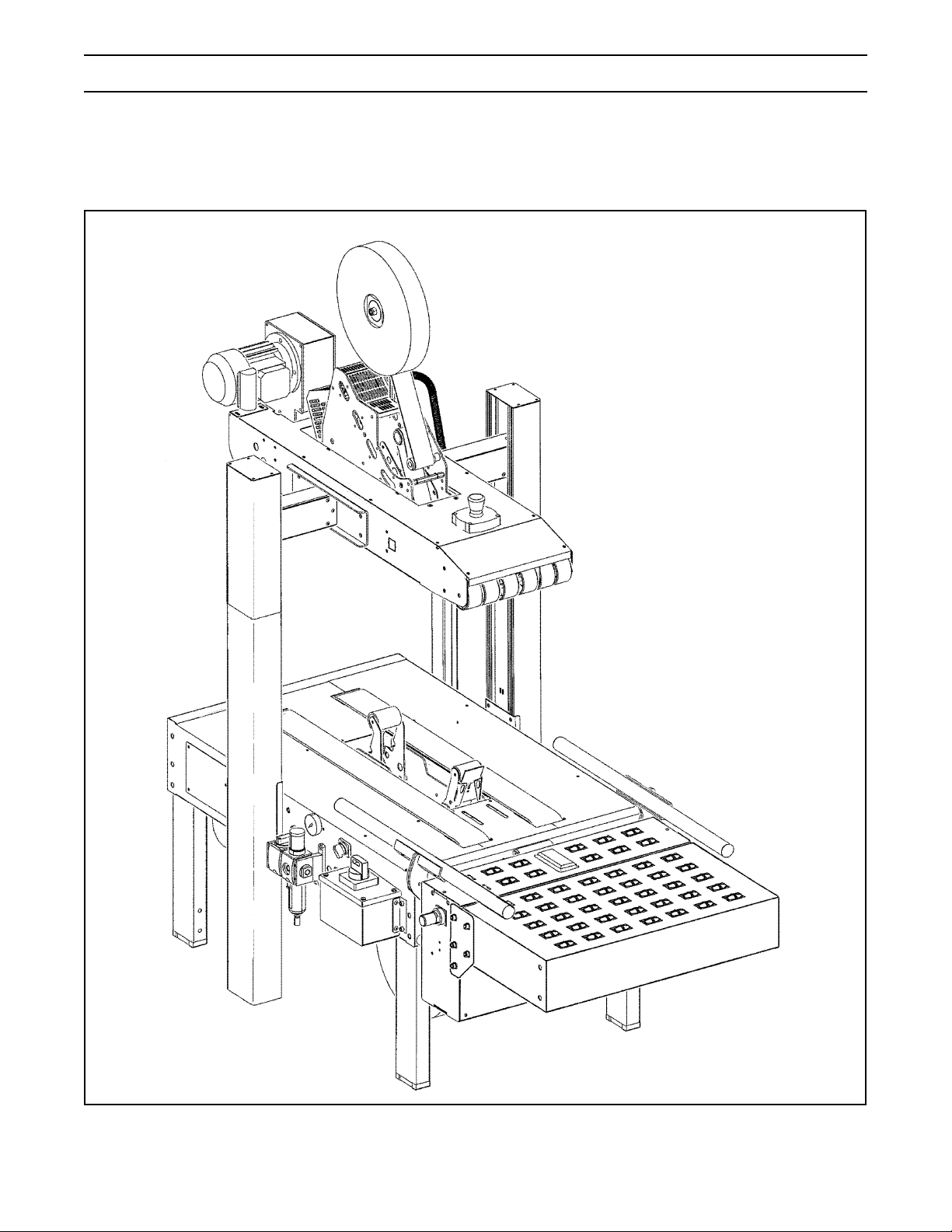
Intended Use
The 3M-MaticTM r70 Random Case Sealer with AccuGlideTM 2+ Taping Heads is designed to apply a “C” clip of
Scotch® pressure-sensitive film box sealing tape to the top and bottom center seam of regular slotted containers.
The r70 automatically adjusts to a wide range of box sizes. See "Specifications Section—Box Weight and Size
Capacities".
3M-MaticTM r70 Random Case Sealer, Type 10700
1
Page 10

Equipment Warranty and Limited Remedy: THE FOLLOWING WARRANTY IS MADE IN LIEU OF ALL OTHER
WARRANTIES, EXPRESS OR IMPLIED, INCLUDING, BUT NOT LIMITED TO, ANY IMPLIED WARRANTY OF
MERCHANTABILITY OR FITNESS FOR A PARTICULAR PURPOSE AND ANY IMPLIED WARRANTY ARISING OUT
OF A COURSE OF DEALING, CUSTOM OR USAGE OF TRADE:
3M sells its 3M-Matic
™
r70 Adjustable Case Sealer, Type 10700
with the following warranties:
1. The drive belts and the taping head knives, springs and rollers will be free from defects in material and
manufacture for ninety (90) days after delivery.
2. All other taping head parts will be free from defects in material and manufacture for three (3) years after
delivery.
3. All other parts will be free from defects in material and manufacture for two (2) years after delivery.
If any part is defective within this warranty period, your exclusive remedy and 3M’s and seller’s sole obligation shall be,
at 3M’s option, to repair or replace the part. 3M must receive actual notice of any alleged defect within a reasonable
time after it is discovered, but in no event shall 3M have any obligation under this warranty unless it receives such notice
within five (5) business days after the expiration of the warranty period. All notices required hereunder shall be given to
3M solely through the 3M-Matic™ Helpline (800-328-1390). To be entitled to repair or replacement as provided under
this warranty, the part must be returned as directed by 3M to its factory or other authorized service station designated
by 3M. If 3M is unable to repair or replace the part within a reasonable time after receipt thereof, 3M, at its option, will
replace the equipment or refund the purchase price. 3M shall have no obligation to provide or pay for the labor required
to remove any part or equipment or to install the repaired or replacement part or equipment. 3M shall have no obligation
to repair or replace those parts failing due to normal wear, inadequate or improper maintenance, inadequate cleaning,
non-lubrication, improper operating environment, improper utilities, operator error or misuse, alteration or modification,
mishandling, lack of reasonable care, or due to any accidental cause.
Limitation of Liability: Except where prohibited by law, 3M and seller will not be liable for any loss or damage arising
from this 3M equipment, whether direct, indirect, special, incidental, or consequential, regardless of the legal theory
asserted, including breach of warranty, breach of contract, negligence, or strict liability.
Note: The foregoing Equipment Warranty and Limited Remedy and Limitation of Liability may be changed only by a
written agreement signed by authorized representatives of 3M and seller.
Contents – r70 Random Case Sealer
(1 ) r70 Random Case Sealer, Type 10700
(1) Upper Tape Drum/Bracket/Hardware
(2 ) Column Bumper Bracket/Hardware
(1 ) Tool/Spare Parts Kit
(1 ) Instruction and Parts Manual
Scotch®, AccuGlideTM, and 3M-MaticTM are Trademarks of 3M, St. Paul, Minnesota 55144-1000
2
Page 11
Important Safeguards
This safety alert symbol identifies
important messages in this manual.
READ AND UNDERSTAND THEM BEFORE
INSTALLING OR OPERATING THIS
EQUIPMENT.
Explanation of Signal Word Consequences
WARNING:
CAUTION:
Indicates a potentially hazardous
situation, which, if not avoided,
could result in death, serious
injury, or property damage.
Indicates a potentially hazardous
situation, which, if not avoided,
may result in minor or moderate
injury, or property damage.
WARNING
• To reduce the risk associated with
mechanical and electrical hazards:
− Read, understand and follow all safety and
operating instructions before operating or
servicing the case sealer.
− Allow only properly trained and qualified
personnel to operate and service this
equipment.
WARNING (continued)
• To reduce the risk associated with impact
hazards:
− Always use appropriate supporting means
when working under the upper drive
assembly.
• To reduce the risk associated with sharp
blade hazards:
− Keep hands and fingers away from tape
cutoff blades under orange blade guards.
The blades are extremely sharp.
• To reduce the risk associated with fire and
explosion hazards:
− Do not operate this equipment in potentially
flammable or explosive environments.
• To reduce the risk associated with muscle
strain:
− Use the appropriate rigging and material
handling equipment when lifting or
repositioning this equipment.
− Use proper body mechanics when removing
or installing taping heads that are moderately
heavy or may be considered awkward to lift.
CAUTION
− Turn electrical and air supply off and
disconnect before performing any
adjustments, maintenance, or servicing the
machine or taping heads.
• To reduce the risk associated with pinches
and entanglement hazards:
− Do not leave the machine running while
unattended.
− Turn the machine off while not in use.
− Never attempt to work on any part of the
machine, load tape, or remove jammed
boxes from the machine while the machine
is running.
• To reduce the risk associated with
hazardous voltage:
− Position electrical cord away from foot and
vehicle traffic.
• To reduce the risk associated with pinches
and entanglement hazards:
− Keep hands clear of the upper head support
assembly as boxes are transported through
the machine.
− Always feed boxes into the machine by
pushing only from the end of the box.
− Keep hands, hair, loose clothing, and jewelry
away from moving belts and taping heads.
• To reduce the risk associated with pinches
and impact hazards:
− Keep away from the pneumatically controlled
upper drive assembly and box centering
guides when air and electric supplies are on.
3
Page 12
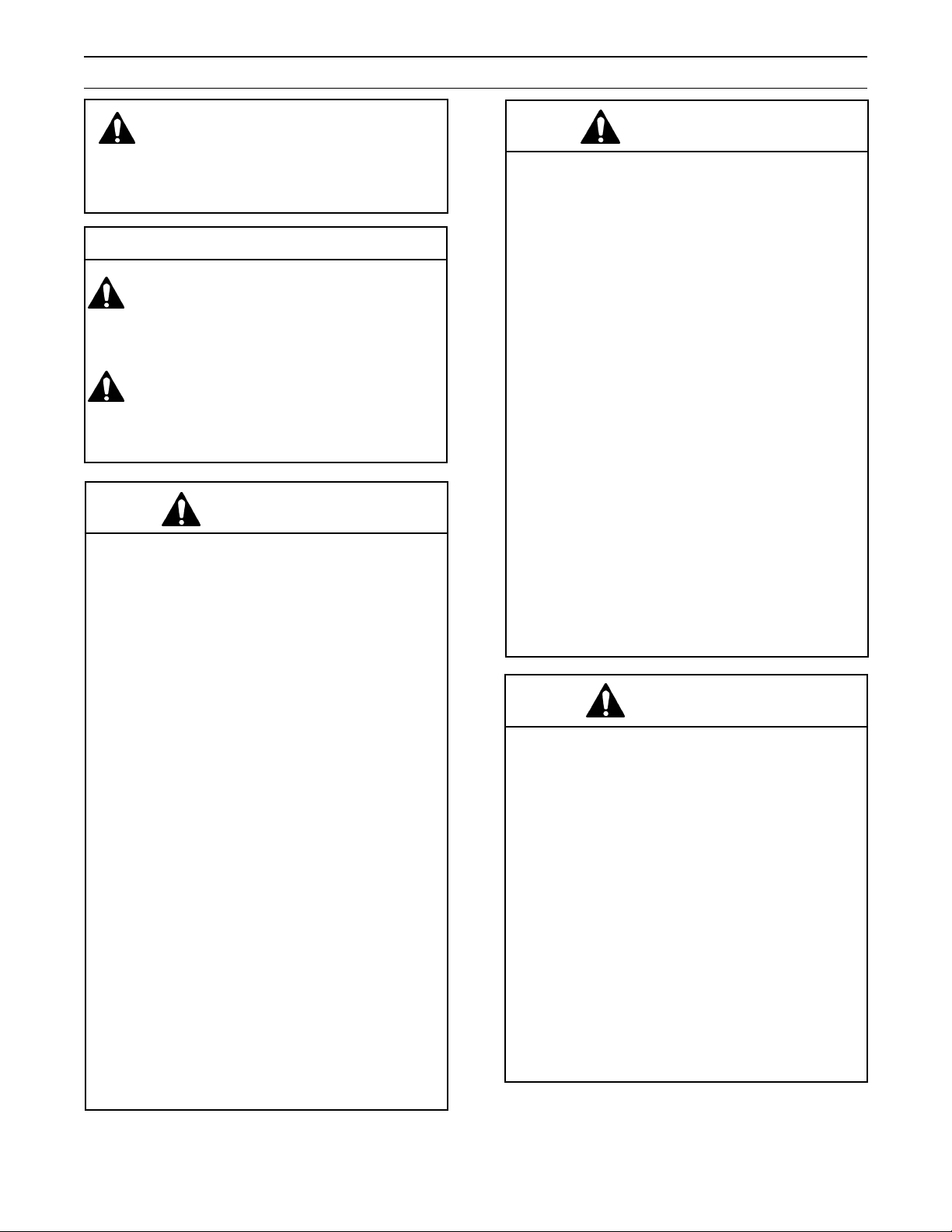
Important Safeguards (Continued)
If the following safety labels are damaged or destroyed, they must be replaced to ensure operator safety. Replace-
ment part numbers for individual labels are shown in Figures 1-1 through 1-3. A label kit, part number 78-8137-12565, is available that includes all labels used on the case sealer. See "Safety and Information Labels," at the end of
Parts Illustration List, Section I.
Figure 1-1 Replacement Labels and 3M Part Numbers
4
Page 13

Important Safeguards (Continued)
WARNING
• To reduce the risk associated with
mechanical and electrical hazards:
− Allow only properly trained and qualified
personnel to operate and service this
equipment.
Operator Skill Level Descriptions
Skill 1: Machine Operator
This operator is trained to use the machine with the
machine controls, to feed cases into the machine,
make adjustments for different case sizes, to change
the tape and to start, stop, and restart production.
Important: The factory manager must ensure
that the operator has been properly trained on
all the machine functions before starting work.
Skill 2: Mechanical Maintenance Technician
This operator is trained to use the machine as the
MACHINE OPERATOR and in addition is able to work
with the safety protection disconnected, to check and
adjust mechanical parts, to carry out maintenance
operations and repair the machine. He is not allowed
to work on live electrical components.
Skill 2a: Electrical Maintenance Technician
This operator is trained to use the machine as the
MACHINE OPERATOR and is able to work with the
safety protection disconnected, to make adjustments,
to carry out maintenance operations and repair the
electrical components of the machine. He is allowed
to work on live electrical panels, connector blocks,
and control equipment.
Skill 3: Specialist From the Manufacturer
Skilled operator sent by the manufacturer or its agent
to perform complex repairs or modifications, when
agreed with the customer.
Operator's Skill Levels Required to Perform the Main Operations on Machine
noitarepOsutatSenihcaM
putesdnanoitallatsnienihcaM
uR
tnemecalperepaT
tnemecalperedalBdetc
ytefashtiwgninn
delbasidsnoitcetorp
ehtgnisserpybdeppotS
nottubPOTSYCNEGREME
ennocsidrewopcirtcelE21
tnemecalpertlebevirDdetcennocsidrewopcirtcelE21
ecnanetniamyranidrOdetcennocsidrewopc
ecnanetniamlacinahcemyranidroartxE
irtcelE21
ytefashtiwgninnuR
delbasidsnoitcetorp
deriuqeR
llikSrotarepO
forebmuN
srotarepO
a2dna22
11
31
anidroartxE
ecnanetniamlacirtceleyr
5
ytefashtiwgninnuR
delbasidsnoitcetorp
a21
Page 14

Specifications
1. Power Requirements:
Electrical: 115 VAC, 60 Hz, 5.6 A (680 watts)
Pneumatic: 5 bar gauge pressure [70 PSIG]
110 liter/min @ 21° C, 1.01 bar [3.75 SCFM] at 15 boxes per minute
A pressure regulator is included
The machine is equipped with two 1/6 HP motors and comes with an 2.4 m [8 foot] standard neoprene covered
power cord and a grounded plug. Contact your 3M Representative for power requirements not listed above.
2. Operating Rate:
Up to 15 boxes per minute. Actual production rate is dependent on box size, box size mix, and operator
dexterity.
Box drive belt speed is approximately 0.38 m/s [75 FPM]
3. Operating Conditions:
Use in dry, relatively clean environments at 4°C to 50°C [40°F to 120°F] with clean, dry, boxes.
Note: Machine should not be washed or subjected to conditions causing moisture condensation on
components.
WARNING
• To reduce the risk associated with fire and
explosion hazards:
− Do not operate this equipment in potentially
flammable or explosive environments.
4. Tape:
Scotch® pressure-sensitive film box sealing tapes.
5. Tape Width:
36 mm or 1.5 inches minimum to 50 mm [2 inches] maximum
6. Tape Roll Diameter:
Up to 405 mm [16 inches] maximum on a 76.2 mm [3 inches] diameter core.
(Accommodates all system roll lengths of Scotch® film tapes.)
7. Tape Application Leg Length—Standard:
70 mm ± 6 mm [2.75 inches ± 0.25 inches]
Tape Application Leg Length—Optional:
(See "Special Setup Procedure")
50 mm ± 6 mm [2 inches ±1/4 inches]
(Specifications continued on next page)
6
Page 15

Specifications (Continued)
8. Box Board:
Style: regular slotted containers, RSC
125 to 275 P.S.I. bursting test, single wall or double wall B or C flute.
23-44 lbs. per inch of width Edge Crush Test (ECT)
9. Box Weight and Size Capacities:
A. Box Weight Range 5 lbs.–65 lbs. [2.3 kg–29.5 kg]. Contents must support flaps.
B. Box Size: Minimum Maximum
Length: 150 mm [6.0 inches] Unlimited
Width: 150 mm [6.0 inches]* 550 mm [21.5 inches]
Height: 120 mm [4.75 inches]** 550 mm [21.5 inches]
* Cartons narrower than 250 mm [10 inches] in width may require more frequent belt replacement
because of limited contact area.
** 95 mm [3.75 inches] height with heads adjusted to apply 50 mm [2 inches] tape leg lengths. See "Special
Setup Procedure".
Note: The case sealer can accommodate most boxes within the size range listed above. However, if the box
length (in direction of seal) to box height ratio is 0.5 or less, then several boxes should be test run to ensure
proper machine performance.
DETERMINE THE BOX LIMITATIONS BY COMPLETING THIS FORMULA:
BOX LENGTH IN DIRECTION OF SEAL = SHOULD BE GREATER THAN 0.5
BOX HEIGHT
Any box ratio approaching this limitation should be test run to ensure proper performance.
(Specifications continued on next page.)
7
Page 16
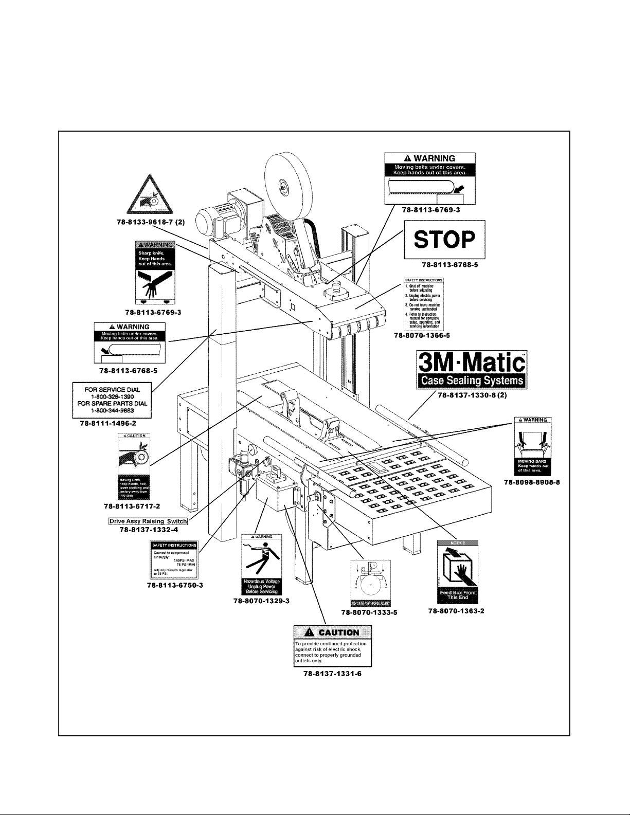
Specifications (Continued)
10. Machine Dimensions:
WL H A 1AB **CF 1FGT
muminiM
mm
)sehcni(
mumixaM
mm
)sehcni(
508
)23(
----0971
0631
5.35
0431
)8.25(
)5.07(
* Exit conveyor is optional
** Casters are optional
Weight – 193 kg [425 lbs.] crated (approximate)
170 kg [375 lbs.] uncrated (approximate)
11. Setup Recommendations:
• Machine must be level.
064
)1.81(
----008
633
)2.31(
545
)5.12(
)5.13(
601
)2.4(
----------
026
)4.42(
026
0
31
)4.42(
)2.5(
0461
)6.46(
• Customer supplied infeed and exit conveyors (if used) should provide straight and level box entry and exit.
• Exit conveyors (powered or gravity) must convey sealed boxes away from machine.
8
Page 17
Installation and Setup
Receiving And Handling
After the machine has been uncrated, examine the
case sealer for damage that might have occurred
during transit. If damage is evident, file a damage
claim immediately with the transportation company
and notify your 3M Representative.
Machine Setup
WARNING
• To reduce the risk associated with
mechanical and electrical hazards:
− Read, understand, and follow all safety and
operating instructions before operating or
servicing the case sealer.
The following instructions are presented in the order
recommended for setting up and installing the case
sealer, as well as for learning the operating functions
and adjustments. Following them step-by-step will
result in thoroughly understanding the case sealer
and installing it in a manner that best utilizes its
many features. Refer to Figure 3-1 to identify the
various components of the case sealer.
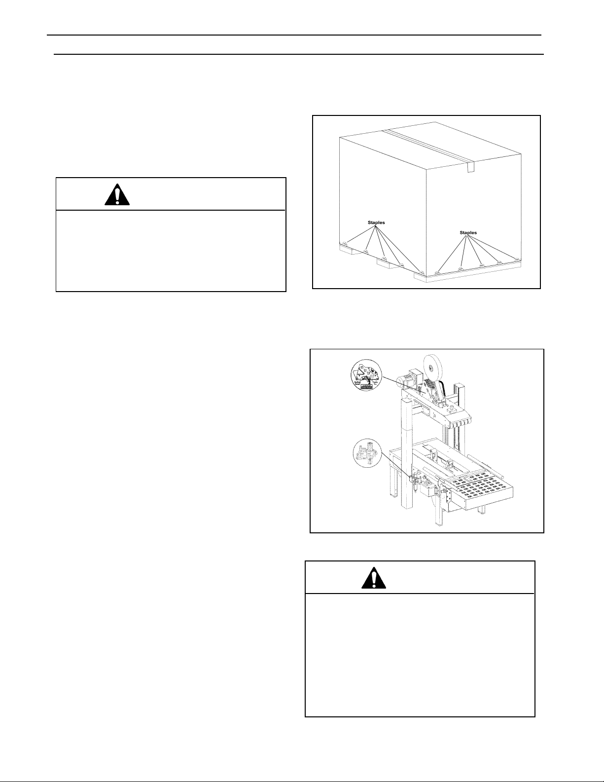
PACKAGING AND SEPARATE PARTS
1. Remove the staples from the shipping carton or
cut around them.
Figure 2-1—Remove Staples
2. Remove the shipping carton from the pallet and
from the machine.
REQUIRED TOOLS
A 17 mm and 21 mm open-end wrench and a 17
mm hex socket wrench are provided with the
machine.
The following customer-supplied tools are required
for machine setup, maintenance, and
adjustments.
• 3 mm hex wrench
• 4 mm hex wrench
• 5 mm hex wrench
• 6 mm hex wrench
• 7 mm combination wrench
• 8 mm combination wrench
• 10 mm combination wrench
• 13 mm combination wrench
• 17 mm combination wrench
• #2 Phillips screwdriver
Figure 2-2—r70 Frame Setup
W ARNING
• To reduce the risk associated with muscle
strain:
− Use the appropriate rigging and material
handling equipment when lifting or
repositioning this equipment.
− Use proper body mechanics when removing
or installing taping heads that are moderately
heavy or awkward to lift.
9
Page 18

Installation and Setup (Continued)
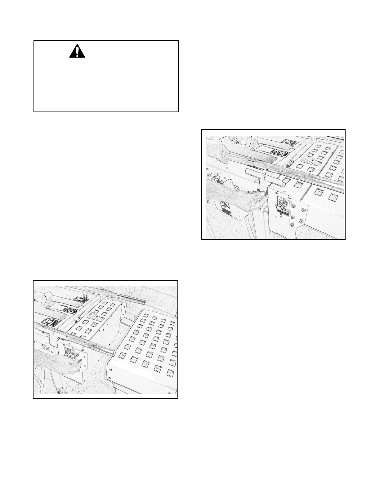
3. Using a 10 mm combination wrench, remove the
fasteners that secure each of the case sealer legs to
the pallet as shown in Figure 2-3.
Figure 2-3—Remove Fasteners
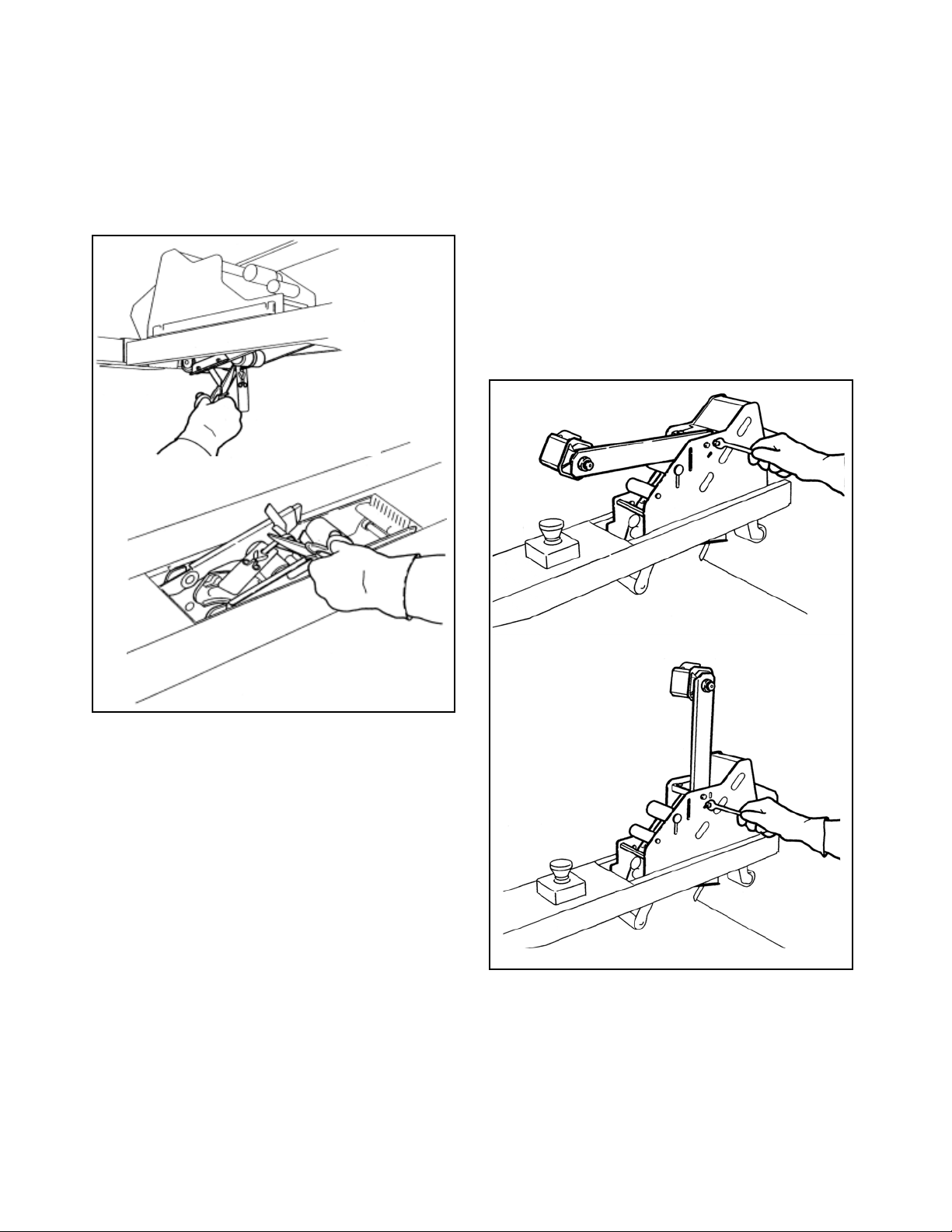
6. Cut the plastic straps that attach the top head to
the frame as shown in Figure 2-4. Retain the tool
and spare parts kit for later use.
4. Remove the leg height adjustment cap screws and
replace with the cap screws from the tool kit.
Remove and replace them one at a time to keep
the inner threaded plate in position.
5. Remove the machine from the pallet and move it
into position.
Important: Whenever the machine is lifted with a
fork truck, ensure that the forks span completely
across the machine frame and do not contact any
wiring or mechanism under the machine frame. In
some cases, the lower taping head may need to
be removed to avoid damage.
WARNING
• To reduce the risk associated with sharp
blade hazards:
− Keep hands and fingers away from tape cutoff
blades under orange blade guards. The
blades are extremely sharp.
Figure 2-4—Cut the Plastic Straps
7. Assemble the column cap onto the column as
shown in Figure 2-5.
8. Fasten the column setscrews as shown in Figure 2-
6.
Figure 2-5—Column Cap Setscrews
10
Page 19
Installation and Setup (Continued)
W ARNING
• To reduce the risk associated with muscle
strain:
− Use the appropriate rigging and material
handling equipment when lifting or
repositioning this equipment.
INFEED CONVEYOR ASSEMBLY
1. Remove the conveyor and the package of parts
from the carton.
2. Verify that the package contains two flat plates,
ten M8 x 20 hex socket head screws, and ten
M8 flat washers.
3. To assemble the infeed conveyor, refer to
Figure 2-2 and locate the three bolt holes on the
infeed end of the case sealer frame and the two
bolt holes on the infeed conveyor.
CENTERING GUIDES
1. Remove the two centering guides and four
M6 x 20 socket head screws from the package.
2. Using a 5 mm hex wrench, attach the centering
guides to the rails with four M6 x 20 screws (two
in each guide) as shown in
Figure 2-3.
4. Place the flat plates over the conveyor and the
frame on each side and secure them with five M8
x 20 screws and M8 washers.
5. Insert a M8 x 20 screw in each hole so that only
a few threads take hold.
Figure 2-3—Centering Guides
Figure 2-2—Infeed Conveyor
11
Page 20
Installation and Setup (Continued)
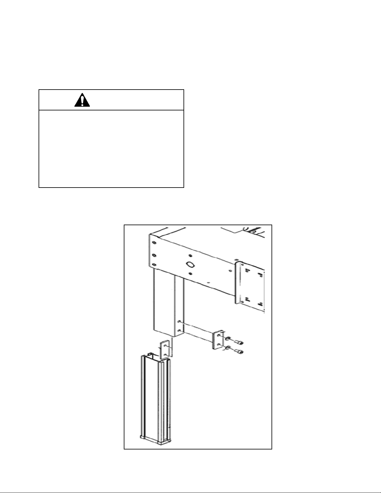
MACHINE BED HEIGHT
The case sealer is equipped with four adjustable
legs that are located at the corners of the
machine frame. The legs can be adjusted to
obtain different machine bed heights. See the
"Specifications" section.
W ARNING
• To reduce the risk associated with muscle
strain:
− Use the appropriate rigging and material
handling equipment when lifting or
repositioning this equipment.
− Use proper body mechanics when removing
or installing taping heads that are moderately
heavy or may be considered awkward to lift.
To adjust the machine bed height, do the
following:
1. Use appropriate material handling equipment
and blocking techniques to raise the machine
frame to allow adequate leg adjustment.
2. Using a 6 mm hex wrench, loosen the socket
head screws that hold the inner leg assembly
to the machine as shown in Figure 2-10.
3. Adjust the leg length for the desired machine
bed height. Adjust all four legs equally.
4. Retighten the screws.
Note: It is not necessary to fasten the
machine to the floor.
TAPE LEG LENGTH
Taping heads are preset to apply 70 mm
[2.75 inches] long tape legs. To change tape leg
length to 50 mm [2.0 inches], refer to Section II,
"Special Setup Procedure—Changing the Tape
Leg Length".
Figure 2-10—Machine Bed Height Adjustment
12
Page 21
Installation and Setup (Continued)
ELECTRICAL CONNECTION AND CONTROLS
The electrical control box (with circuit breaker)
and "On/Off" switch are located on the left side of
the machine frame. See Figure 3-1. If desired, for
operator convenience, the "On/Off" switch can be
relocated to the right side of the machine frame.
A standard three-conductor power cord with plug
is provided at the back of the electrical control
box. The receptacle providing this service shall be
properly grounded. Before the power cord is
plugged into a 115 Volt, 60 Hz outlet, verify that
all packaging materials and tools are removed
from the machine. Do not plug electrical cord
into outlet until ready to run machine.
Use of an extension cord is not recommended.
However, if one is needed for temporary use, it
must have a wire size of 1.5 mm diameter
[AWG 16 ], have a maximum length of 30.5 m
[100 ft], and must be properly grounded.
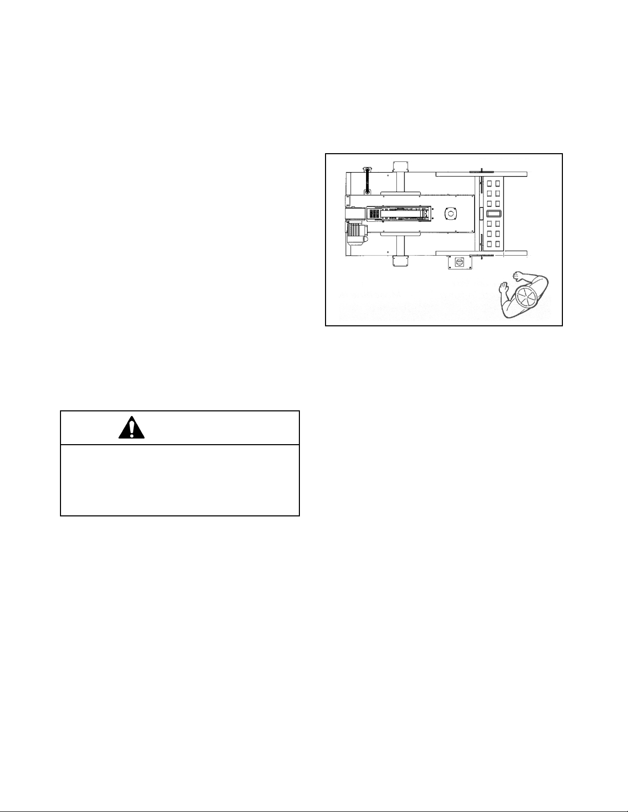
OPERATOR WORKING POSITION
Figure 2-11 illustrates the correct operator
working position.
Figure 2-11—Operator Working Position
WARNING
• To reduce the risk associated with
hazardous voltage:
− Position electrical cord away from foot and
vehicle traffic.
Note: Machines outside the U.S. may be
equipped with 220/240 Volt, 50 Hz systems or
other electrical requirements compatible with
local practice.
SPACE REQUIREMENTS
The left side of the machine must be a minimum
of 1.0 m (39.4 inches) from the nearest wall.
The right side of the machine must be a minimum
of 0.7 m (27.6 inches) from the nearest wall.
The machine requires a minimum of 2.7 m (106.3
inches) height.
13
Page 22

Installation and Setup (Continued)
PNEUMATIC CONNECTION
Important: Use care when working with
compressed air.
The case sealer requires a 5.2 bar gauge
pressure 110 liter/min [75 PSIG], @ 21°C, 1.01
bar [3.75 SCFM] compressed air supply. As
shown in Figure 3-1, an on/off valve, pressure
regulator, and filter are provided to service the air
supply.
Note: A precision regulator is used to balance
the top drive assembly. Due to the selfrelieving feature of this regulator, a small
amount of air continually vents to the atmosphere. This is normal and amounts to
approximately 3 liter/min. [0.1 SCFM].
1. Read and remove safety tag from pneumatic
"On/Off" valve.
2. Connect the main air supply line to the inlet
side of the On/Off valve using the barbed
fitting and hose clamp provided. The
customer supplied air hose
(8 mm [5/16 inches] Inner Diameter) must be
clamped tightly to the barbed fitting.
4. Raise the upper drive assembly to full Up position
by turning the drive assembly raising switch
clockwise.
If another type of connector is desired, the
barbed fitting can be removed and replaced
with the desired 1/4-18 NPT threaded
connector.
Always turn the air valve Off when the air
supply line is being connected or
disconnected.
3. Turn the air supply on by turning the air On/Off
valve to On.
Note – The air valve has provisions for lock
out/tag out according to plant regulations.
WARNING
• To reduce the risk associated with impact
hazards:
− Always use appropriate supporting means
when working under the upper drive
assembly
14
Page 23
Installation and Setup (Continued)
TAPING HEAD SETUP
1. Cut the plastic ties holding the upper and lower
taping heads in position, as shown in Figure 2-8.
Hold taping head Buffing Roller while cutting the
plastic tie. Allow buffing/applying arms to extend
slowly.
2. Verify that the upper and lower taping heads
move freely by pushing the buffing roller into the
taping head.
3. Using a 10 mm open-end wrench, loosen the
capscrew on the tape drum bracket assembly
and move the assembly to the vertical position,
as shown in Figure 2-9. Install additional
capscrews from the tool kit. The tape drum
bracket assembly can be pivoted as necessary
to provide tape roll clearance from the floor or
overhead obstacles.
Figure 2-8—Cut the Plastic Ties
Figure 2-9—Lower Tape Drum Bracket Position
INITIAL STARTUP OF CASE SEALER
After completing the "Installation and Setup"
procedure, continue through "Operation" for tape
loading and startup to ensure that the case sealer
is properly adjusted to run boxes.
15
Page 24
Operation
WARNING
• To reduce the risk associated with mechanical and electrical hazards:
− Read, understand, and follow all safety and operating instructions before operating or
servicing the case sealer
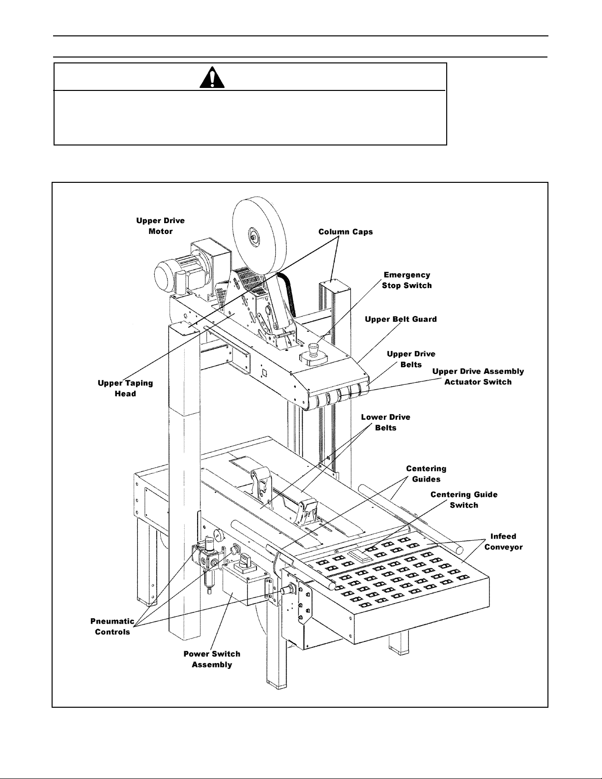
Refer to Figure 3-1 and 3-2 below to acquaint yourself with the various components and controls of the case
sealer. Also see Figures 3-1 and 3-2 in Section II for taping head components.
Figure 3-1—r70 Case Sealer Components (Left Front View)
16
Page 25
Operation (Continued)
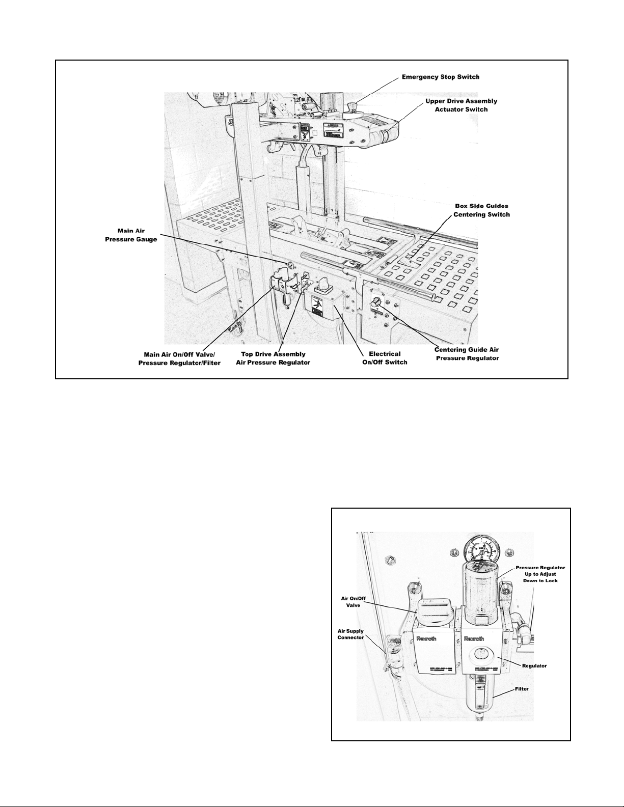
Figure 3-2—Controls, Valves and Switches
Electrical On/Off Switch (Figure 3-2)
The box drive belts are turned on and off with the
electrical switch on the side of the machine
frame.
The case sealer has a circuit breaker located in
the electrical enclosure on the left side of the
machine frame. If circuit becomes overloaded
and circuit
electrical
After two minutes, plug machine electrical cord
into outlet and restart machine by rotating the
On/Off switch to Off (O) then On (I).
Main Air On/Off Valve/Pressure Regulator/
Filter (Figure 3-3)
This set of pneumatic components controls,
regulates and filters plant air supply to the two
separate control circuits of the case sealer.
On/Off Valve (Figure 3-2)
On—turn arrows on switch toward the front of the
machine; Off—turn arrows on switch toward the
left side of the machine.
breaker trips, unplug the machine
cord and determine cause of overload.
Always turn off the air when machine is not in
use, when servicing the machine, or when
connecting or disconnecting air supply line.
Note: The air valve has provisions for lockout/
tagout according to plant regulations.
Note: Turning air supply off automatically bleeds
air pressure from the case sealer air circuits.
Figure 3-3—On/Off Valve/Regulator/Filter
17
Page 26
Operation (Continued)
Pressure Regulator (Figure 3-3)
Regulates main air pressure to the machine to
adjust pressure, pull knob up and turn; push
down to lock setting.
Filter (Figure 3-3)
Removes dirt and moisture from plant air before
it enters the case sealer pneumatic circuits. If
water collects in bottom of bowl, unscrew the
valve on the bottom of bowl to drain. When
empty, retighten valve.
Emergency Stop Switch (Figure 3-2)
The machine electrical supply can be turned off
by pressing the latching emergency stop
switch. To restart machine, rotate emergency
stop switch a quarter turn clockwise to releases switch latch. Restart machine by
turning the switch to the "O" (Off) position then
to "I" (On).
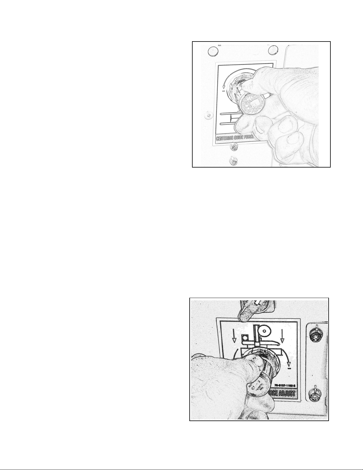
Figure 3-4—Air Regulator, Centering Guides
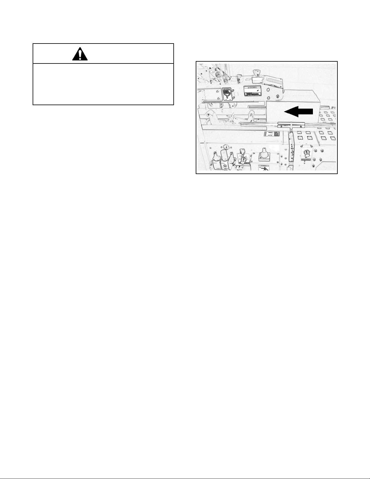
Upper Drive Assembly Actuator Switch
(Figure 3-2)
This switch, when touched by the leading edge
of a box , pneumatically raises the upper drive
assembly to allow insertion of the box under
the drive belts. As the box moves under the
switch, releasing it, the upper drive assembly
descends on the box and the drive belts
convey the box through the machine. When
switch is turned, the upper drive assembly
rises. When the switch is released, the upper
drive assembly descends to its rest position.
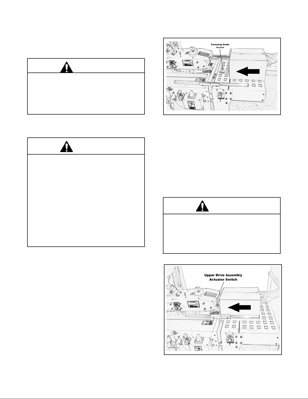
Centering Guide Switch (Figure 3-7)
This pneumatic switch controls the box
centering guides. When switch is activated by
a box entering the case sealer, the centering
guides close (centering the box), and released
(after box passes over switch), the guides
open.
Air Pressure Regulator, Centering Guide
Force Adjustment (Figure 3-4)
This regulator is used to adjust centering
guides according to weight of boxes. Pressure
should be adequate to center boxes, but low
enough to allow easy pushing of boxes under
taping head.
Air Pressure Regulator, Top Drive Assembly
Force Adjustment (Figure 3-5)
Set nominally to control the "down" movement of
top drive assembly and the pressure exerted
against the box as shown in Figure 3-5. The
regulator setting is changed as necessary for the
boxes being sealed to provide adequate drive belt
pressure against the box to positively convey the
boxes through the machine. If the boxes stop or
hesitate while being conveyed, decrease the
regulator pressure. This increases the drive belt
force on the box for more friction between the box
and drive belts. Adjust the pressure setting as
necessary to get continuous movement of boxes
through the machine.
To adjust the regulator setting, pull the knob
outward, rotate the knob to the desired setting.
Push the knob inward to lock it and prevent
unintentional adjustment.
Figure 3-5—Air Regulator/Gauge, Top Drive
Assembly
18
Page 27

Operation (Continued)
For boxes which are fully packed with products
that support the top flaps, the adjustment of this
regulator is not critical since the boxes can
support the pressure of the upper frame (drive
belts) at a wide range of regulator settings.
However, if under-filled or fragile boxes are
sealed, this regulator can be used to set the
upper frame pressure to a reduced level that is
still adequate to positively convey the box and to
prevent damage of boxes. The regulator setting
can be locked by pushing the knob inward.
Note: A precision regulator is used to
balance the top drive assembly. Due to
the self relieving feature of this regulator a
small amount of air will continually vent to
the atmosphere. This is normal and
amounts to approximately 3 liter/min
[0.1 SCFM ].
Figure 3-6—Mechanical Latch, Upper
Drive Assembly
Main Air Pressure Gauge (Figure 3-2)
Indicates main air regulator pressure setting. Air
regulator should be adjusted so gauge reads 5.2
bar gauge pressure [75 PSIG].
Pneumatic Valve, Drive Assembly Raising
Switch (Figure 3-6)
The Pneumatic Valve Drive Assembly Raising
Switch is used to hold the upper drive assembly
to its fully raised position for tape threading and
maintenance.
To raise the drive assembly, turn the switch to
the right. To lower the drive assembly to its fully
lowered position, turn the switch to the left.
19
Page 28
Operation (Continued)
Tape Loading/Threading
See Section II.
WARNING
• To reduce the risk associated with muscle
strain:
− Use proper body mechanics when removing
or installing taping heads that are moderately
heavy or may be considered awkward to lift.
Theory of Operation
Figure 3-7—Centering Guide Switch
CAUTION
• To reduce the risk associated with pinches
and entanglement hazards:
− Always feed boxes into the machine by
pushing only from the end of the box.
− Keep hands clear of the upper head support
assembly as boxes are transported through
the machine.
• To reduce the risk associated with pinches
and impact hazards:
− Keep away from the pneumatically controlled
upper drive assembly and box centering
guides when air and electric supplies are on.
The air supply powers movement of the centering
guides and upper drive assembly to automatically
adjust the case sealer to the box size being sealed
as follows:
1. A box centering switch in the center of the
infeed roller conveyor actuates movement of the
centering guides. When the operator pushes a
box onto the infeed conveyor, as shown in
Figure 3-7, the lever is depressed causing the
air cylinder powered centering guides to move
inward, centering the box.
2. Once the box is centered by the guides, the
operator pushes the box against the raising
switch on the upper drive assembly, as shown in
Figure 3-8, two air cylinders raise the upper drive
assembly. The upper taping head will continue
to rise above the box height so the operator can
insert the box underneath the upper drive belts.
CAUTION
• To reduce the risk associated with pinches
and entanglement hazards:
− Keep hands clear of the upper head support
assembly as boxes are transported through
the machine
Figure 3-8—Upper Drive Assembly Actuator
Switch
20
Page 29
Operation (Continued)
CAUTION
• To reduce the risk associated with pinches
and entanglement hazards:
− Keep hands, hair, loose clothing, and jewelry
away from moving belts and taping heads
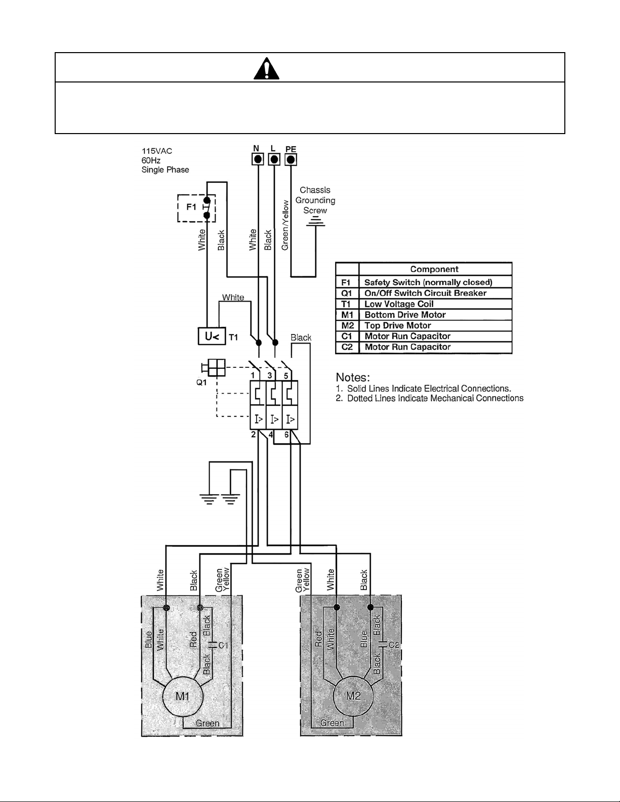
3. Once the box is pushed under the upper taping
head, the upper drive assembly actuator switch
is releases to lower the upper drive assembly to
descend onto the box top, as shown in
Figure 3-9, allowing the drive belts to convey the
box through the upper and lower taping heads for
application of the tape seals.
4. As the box is conveyed through the machine, the
centering guide switch is released causing the
centering guides to return to their full open
position, ready for insertion of the next box.
5. Once the box is conveyed from under the upper
taping head, the upper drive assembly descends
to its rest position, ready for insertion of the next
box.
At this point it is recommended that the centering
guides and upper drive assembly switches be
manually actuated to better understand their
functions. Depress the centering guide switch to
close the guides. Release the switch to open the
guides. Depress the upper drive assembly raising
switch to raise the upper drive assembly. Release
the upper drive assembly raising switch to lower the
drive assembly.
Figure 3-9—Box Conveyed Through Machine
Machine or taping head adjustments are described
in "Adjustments" Section I for machine or Section
II for taping heads.
Note: Box drive motors are designed to run at
a temperature somewhat above ambient
room temperature. A motor may feel hot
to the touch during normal operation.
Box Sealing
1. Turn main air valve to (On).
Important: Before turning drive belts on, be sure
no tools or other objects are on the conveyor bed.
2. Turn the switch on side of machine frame to start
drive belts.
3. Feed boxes to machine. Always allow previous
box to exit machine BEFORE feeding next box.
4. Turn air and electrical supplies "Off" when
machine is not in use.
5. Reload and thread tape as necessary.
6. Be sure machine is cleaned and lubricated
according to recommendations in "Maintenance"
section of this manual.
21
Page 30

Maintenance
The case sealer has been designed for long, trouble
free service. The machine performs best when it
receives routine maintenance and cleaning.
Machine components that fail or wear excessively
should be promptly repaired or replaced to prevent
damage to other portions of the machine or to the
product.
WARNING
• To reduce the risk associated with
mechanical and electrical hazards:
− Turn electrical and air supply off and
disconnect before performing any
adjustments, maintenance, or servicing the
machine or taping heads.
• To reduce the risk associated with impact
hazards:
− Always use appropriate supporting means
when working under the upper drive
assembly.
Lubrication
The machine bearings, including the drive motor, are
permanently lubricated and sealed and do not require
additional lubricant.
Cleaning
Note – Never attempt to remove dirt from
the machine by blowing it out with
compressed air. This can cause the dirt to
be blown inside the motor and onto sliding
surfaces which may cause premature
equipment wear. Never wash or subject
equipment to conditions causing moisture
condensation on components. Serious
equipment damage could result.
Regular slotted containers produce a great deal of
dust and paper chips when processed or handled in
equipment. If this dust is allowed to buildup on
machine components, it can cause component wear
and overheating of drive motor. The dust buildup can
best be removed from the machine by a shop vacuum.
Depending on the number and type of boxes sealed in
the case sealer, this cleaning should be done approximately once per month. If the boxes sealed are dirty,
or if the environment in which the machine operates is
dusty, cleaning on a more frequent basis may be
necessary. Excessive dirt buildup that cannot be
removed by vacuuming should be wiped off with a
damp cloth.
22
Page 31

Maintenance (Continued)
WARNING
• To reduce the risk associated with mechanical and electrical hazards:
− Turn electrical and air supply off and disconnect before performing any adjustments, maintenance, or
servicing the machine or taping heads
Circuit Breaker
The case sealer is equipped with a circuit breaker
which trips if the motors are overloaded. Located
inside the electrical enclosure on the side of the
machine frame. The circuit breaker has been preset
at the factory to 4.5 amps and requires no further
maintenance.
If circuit is overloaded and circuit breaker trips:
1. Determine cause of overload and correct.
2. Rotate the switch mechanism to the "O" (Off)
position then to "I" (On). If circuit breaker will
not reset, wait 2 minutes and retry.
Knife Replacement, Taping Head
See Section II, "Maintenance—Blade (Knife)
Replacement."
Box Drive Belt Replacement
3M recommends replacing drive belts in pairs,
especially if belts are unevenly worn.
DRIVE PULLEY RINGS
Before installing a new belt, check the orange plastic
drive pulley rings for wear. If torn, broken, or worn
smooth, replace the rings.
Figure 4-1—Drive Pulley Rings
23
Page 32

Maintenance (Continued)
WARNING
• To reduce the risk associated with mechanical and electrical hazards:
− Turn electrical and air supply off and disconnect before performing any adjustments, maintenance, or
servicing the machine or taping heads.
LOWER DRIVE BELTS
1. Using a 17 mm open end wrench, loosen, but do
not remove the lock nut as shown in Figure 4-2.
2. Using a 6 mm hex wrench, loosen tension screw
until all belt tension is removed as shown in
Figure 5-2.
3. Pull out belt splicing pin.
Tip: The old belt may be used to install the new
belt. Attach the new belt to the old belt and pull
the new belt into the position while removing the
old belt.
4. If the old belt cannot be used to install a new belt,
remove the upper drive cover. If using the old belt,
continue with the next step.
5. Place new belt over pulleys with laced splice at
top.
6. Insert splicing pin.
Important: Pin must not extend beyond edge of
belt.
7. Adjust belt tension as explained in
"Adjustments—Box Drive Belt Tension."
UPPER DRIVE BELTS
1. Using a 17 mm open end wrench, loosen, but
do not remove the lock nut as shown in Figure
4-3.
2. Using a 6 mm hex wrench, loosen tension
screw until all belt tension is removed as shown
in Figure 5-3.
3. Move compression roller assembly out to full
open position (If installed).
4. Pull out belt splicing pin.
Tip: The old belt may be used to install the new
belt. Attach the new belt to the old belt and pull
the new belt into the position while removing the
old belt.
5. If the old belt cannot be used to install a new
belt, remove the upper drive cover. If using the
old belt, continue with the next step.
6. Place new belt over pulleys with laced splice at
top.
7. Insert splicing pin.
Important: Pin must not extend beyond edge of
belt.
Figure 4-2—Lower Drive Belt Replacement
8. Adjust belt tension as explained in
"Adjustments—Box Drive Belt Tension."
Figure 4-3—Upper Drive Belt Replacement
24
Page 33

Adjustments
WARNING
• To reduce the risk associated with mechanical and electrical hazards:
− Turn electrical and air supply off and disconnect before performing any adjustments, maintenance, or
servicing the machine or taping heads.
Box Drive Belt Tension
The four continuously moving drive belts convey boxes through the tape applying mechanism. The box drive belts
are powered by electric motors.
Tension adjustment of these belts may be required during normal operation. Belt tension must be adequate to
positively move the box through the machine and the belts should run fully on the surface of the pulleys at each end
of the frame. The idler pulleys on the infeed end are adjusted in or out to provide proper belt tension. Each belt is
adjusted separately.
Belt tension is obtained by tightening the adjustment screw so that a moderate pulling force of 3.5 kg [7 lbs.]
applied at the midspan, as shown in Figure 5-1, will deflect the belt 25 mm [1 inch]. This ensures positive contact
between the belt and the drive pulley on the discharge end of the drive assembly. Figure 5-1 illustrates the lower
drive belts. The upper drive belts are adjusted in the same manner.
Figure 5-1—Box Drive Belt Tension Adjustment
25
Page 34

Adjustments (Continued)
WARNING
• To reduce the risk associated with mechanical and electrical hazards:
− Turn electrical and air supply off and disconnect before performing any adjustments, maintenance, or
servicing the machine or taping heads.
Refer to Figures 5-2 and 5-3 and adjust belt tension as follows:
1. Using a 17 mm open end wrench, loosen, but do not remove, the M10 lock nut. Refer to Figures 4-2 and 4-3.
2. Reset the tension on the drive belts as needed. Using a 6 mm long shank hex wrench (approximately 9 inches
[230 mm] long), adjust the M8 tension screws in (clockwise) to increase tension or out (counterclockwise) to
decrease tension.
3. Tighten the M10 lock nut to secure the tension setting.
Figure 5-2—Box Drive Belt Tension Adjustment, Lower Belts (Infeed End)
26
Page 35

Adjustments (Continued)
WARNING
• To reduce the risk associated with mechanical and electrical hazards:
− Turn electrical and air supply off and disconnect before performing any adjustments, maintenance, or
servicing the machine or taping heads.
Figure 5-3—Box Drive Belt Tension Adjustment, Upper Belts (Infeed End)
Taping Head Adjustments: Refer to Section II
WARNING
• To reduce the risk associated with sharp blade hazards:
− Keep hands and fingers away from tape cutoff blades under orange blade guards. The blades are
extremely sharp.
TAPE WEB ALIGNMENT: Section II
TAPE DRUM FRICTION BRAKE: Section II
APPLYING MECHANISM SPRING: Section II
ONE-WAY TENSION ROLLER: Section II
TAPE LEG LENGTH ADJUSTMENT: Section II
27
Page 36

Adjustments (Continued)
WARNING
• To reduce the risk associated with mechanical and electrical hazards:
− Allow only properly trained and qualified personnel to operate and service this equipment.
− Turn electrical and air supply off and disconnect before performing any adjustments, maintenance, or
servicing the machine or taping heads.
Centering Rail Timing Adjustment
The centering rails position and hold the box in the
center of the infeed conveyor until it contacts the drive
belts. A flow control valve located at the front of the
machine determines the amount of time that these
guides are in contact with the box. This valve is preset
at the factory. However, changes to the plant air
supply and adjustments to the case sealer pneumatic
system for your specific application may alter performance of the centering rails.
The centering rails should close against the box until
the drive belts engage and then release the box.
Indications of improper operation include the rails
moving away from the box before the drive belts pull the
box through the machine (short box applications) and
the rails moving inward after the box passes through
the centering rails.
To adjust the Centering Rail timing, do the following:
1. Turn off the air supply and unplug the power cord.
2. Remove Entrance conveyor (if installed).
3. Remove Infeed Frame Cover Plate.
4. Turn the Flow Regulator knob (Figure 5-5) clockwise slightly to increase the dwell time or counterclockwise slightly to decrease the dwell time.
5. Replace cover temporarily to prevent access to
moving parts.
6. Turn on the air supply and plug in the power cord.
7. Run a box through the machine and observe the
operation.
8. Repeat steps 1–7 until the centering rails operate
properly.
9. Replace Infeed Frame Cover plate and Entrance
conveyor (if installed).
Figure 5-4—Timing Adjustment
28
Page 37

Removing Taping Heads
WARNING
• To reduce the risk associated with mechanical and electrical hazards:
− Turn electrical and air supply off and disconnect before performing any adjustments, maintenance, or
servicing the machine or taping heads.
• To reduce the risk associated with sharp blade hazards:
− Keep hands and fingers away from tape cutoff blades under orange blade guards. The blades are extremely
sharp.
WARNING
• To reduce the risk associated with muscle strain:
− Use proper body mechanics when removing or installing taping heads that are moderately heavy or may be
considered awkward to lift.
1. Remove tape from upper taping head and raise
upper assembly to a convenient working height.
2. Loosen the thumb screws and move the clamp
that secures the upper taping head as shown in
Figure 6-1.
Figure 6-1—Loosen Thumb Screws
3. Slide the taping head forward and lift upward to
remove.
4. Raise upper assembly to provide working room
around lower taping head and remove tape from
taping head.
5. Lift the lower taping head, shown in Figure 6-3
straight up to remove it from the case sealer
bed.
7. Replace taping heads in the reverse order of
disassembly.
Figure 6-2—Remove Upper Taping Head
Figure 6-3—Remove Lower Taping Head
29
Page 38

Troubleshooting Guide
The Troubleshooting Guide lists some possible machine problems, causes, and corrections. Also see Section II
"Troubleshooting" for taping head problems.
melborPesuaCnoitcerroC
sexobworraN
nahtreworranerasexoB
gnisuac,dednemmocer
tamerpdnaegappils
.raew
sgnirnoitcirfrostlebevirdnroW
sgnir
tonodstlebevirD
sexobyevnoc
thgit
hgih
tonodstlebevirD
nrut
gnittes
hgnipatpoT
.erusserphguone
gnissim
simronroW
wolootnoisnettlebevirD
tcennocsidlacirtcelE
ylppatonseoddae
eldnahknarcehtgnisu
ootsrellornoisserpmocpalfpoT
redlohgnirpsgniylppadaehgnipaT
gnirpsgniylppadaehgnipaT
sgnirnoitcirfgnis
tcerroctatonrekaerbtiucriC
oottes
wopkcehC
redlohgnirpsecalpeR
erusserpgnirpsecudeR
sgnirnoitcirfecalpeR
noisnettlebtsujdA
.snoitacificepsenihcamkcehC
tleberu
noitcirfrostlebevirdecalpeR
tnemtsujdathgiehxobehttsujdA
srellornoisserpmoctsujdaeR
gulplacirtcelednare
eulavtnerructcerrocotteS
fretni
rehto
sa
(Continued)
gninruttonrotoM
re
kaerbtiucriC
roticapacrotoM
detnedrevocnafrotoM
rewoldnareppU
daehgnipat
smsinahcem
hcaehtiwere
kaerbstlebevirD
maj
pitsexobthgiL
ixenokcab
t
esiongnikaeuqS
ssapsexob
enihcamhguorht
deretnectonepaT
maesxobno
rafoot
gnitteshtgnel
tlebnroW
srellornoisserpmocyrD
sgniraebnmulocyrD
deretnectonmurdepaT
sediuggniretneC
potsthgiehmuminims'enihcaM
geldaehepathctamtonseod
gnittes
tlebecalpeR
otsexobgnisuacputesreporpmI
nwodylbmessadaehreppureppU
buL
sgniraebnmulocevitcefeD
deretnecton
htgnellauqenufospalfxoB
hctamsdaehgnipat
ylbmessadaeh
murdepatnoitisopeR
sediuggniretnectsujdA
tcerrocdnamelborpetaulavE
erusekamotlaunamkcehC
enihcam
reppurepputsujdaylluferaC
srellornoisserpmocetacir
sgniraebnmulocetacirbuL
sgniraebnmulocecalpeR
snoitacificepsxobkcehC
30
Page 39

Troubleshooting Guide (Continued)
melborPesuaCnoitcerroC
erusserpriarewoL
evirdreppU
tonseodylbmessa
sevomropuevom
ylwolspu
daehgnipatreppU
evomtonseod
fodneehttanwod
t
elcycgnipateh
itcefeD
daeh
rotalugertsujda
srednilycgnisiar
thgiloottesrotaluger
.evlavgnisiardaehev
evlav
rotautcaevlavgnisiardaehkroW
tsuahxedegamadrodeggolC
ehtfosdnereppuehtnosrelffum
evlavrewopdaehevitcefeD
tsujdaecrofylbmessaevirdreppU
ecrofylbmessaevirdpotevitcefeD
srelffum
evlavecalpeR
erronaelC
evlavrewop
colcretnuoc
rotalugerecalpeR
.ylppusriaehttcennocsiD
erusserprianiamehttahtyfireV
.orezsdaerrotaluger
tsujdadnaylppusriatcennoceR
.)rab5(GISP07otrotaluger
gnisiardaehecalperronaelC
tsuahxeecalp
daehehtecalperronaelC
ylbmessaevirdreppuehtnruT
rotalugertsujdaecrof
ehtesaercniotesiwk
.xobehtfopotehttsniagaecrof
aw-enoevitcefeD
U
evirdrepp
sevomylbmessa
rotsafootnwod
drahoot
sediuggniretneC
nahtrewolsevom
.lamron
vitcefeD
evlav
evlavy
evlavrewopdaehevitcefeD
tsujdaecrofylbmessaevirdreppU
T
hgihoottesrotaluger
ylbmessaevirdreppue
rotalugertsujdaecrof
detsujdaylreporpmiwercsnoihsuC
gnissimwercsnoihsuC
tsujdaecrofediuggniretneC
woloottesrotaluger
dnilycediuggniretneC
deepsre
detsujdayltcerroctonslortnoc
rewopediuggniretnecevitcefeD
jdA
wercsecalpeR
rotalugertsujdA
evlavecalperronaelC
evlavecalperronaelC
ylbmessaevirdreppuehtnru
esiwkcolcrotalugertsujdaecrof
tsniagaecrofehtesaercedot
.xobehtfopoteht
rotalugerecalpeR
wercsnoihsuctsu
detnuomslortnocdeepstsujdA
rednilycediuggniretnecno
evlavecalperronaelC
31
Page 40
Electrical Diagram
WARNING
•
To reduce the risk associated with mechanical and electrical hazards:
− Turn electrical and air supply off and disconnect before performing any adjustments, maintenance, or
servicing the machine or taping heads.
32
Page 41

Pneumatic Diagram
WARNING
• To reduce the risk associated with mechanical and electrical hazards:
− Turn electrical and air supply off and disconnect before performing any adjustments, maintenance, or
servicing the machine or taping heads.
Figure 8-1—Pneumatic Diagram
33
Page 42

Replacement Parts and Service Information
Spare Parts
The following parts are normal wear items and should be ordered and kept on hand as required.
Qty. Ref. No. Part Number Description
4 10677-8 78-8070-1531-4 Belt, Drive, with Pin
In addition, a tool and spare parts kit supplied with the r70 Random Case Sealer contains the following spare parts:
Qty. Ref. No. Part Number Description
1 10387-10 (Sec. II) 78-8070-1274-1 Spring, Upper Extension (Silver)
1 10389-10 (Sec. II) 78-8070-1273-3 Spring, Lower Extension (Black)
2 10391-2 (Sec. II) 78-8017-9173-8 Knife, 65 mm (2.56 inches)
4 10391-12 (Sec. II) 78-8052-6602-6 Spring, Cutter
All the above listed parts can be ordered separately and when used should be ordered and kept on hand for
spares.
Refer to Section II for recommended taping head spare parts.
Label Kit
If any labels are damaged or destroyed, they must be replaced to ensure operator safety. A label kit (part number
78-8137-1256-5) is available as a stock item. It contains all the safety labels used on the r70 Random Case Sealer.
Tool Kit
A tool kit, part number 78-8098-8868-4, is available for the machine. The kit contains the necessary open end and
hex socket wrenches for use with the metric fasteners on the case sealer. The threading tool, part number 78-80764726-4, contained in above kit is also available as a replacement stock item.
Replacement Parts Ordering Information and Service
Refer to the first page of this instruction manual "Replacement Parts and Service Information".
34
Page 43

Options and Accessories
For additional information on the options and accessories listed below, contact your 3M Representative.
Part Number Option/Accessory
70-0064-2998-2 Caster Kit Attachment
70-0064-2999-0 Conveyor Extension Attachment (exit only)
70-0064-0353-2 AccuGlide™ 2+ STD 2 Inch Upper Taping Head, Type 10500
70-0064-0354-0 AccuGlide™ 2+ STD 2 Inch Lower Taping Head, Type 10500
70-0064-3000-6 Compression Roller Kit
78-8098-8868-4 Tool and Parts Kit
78-8076-4834-6 6 mm Long Shank hex wrench
35
Page 44

THIS PAGE IS BLANK
36
Page 45

Replacement Parts – Illustrations and Parts Lists
r70 Random Case Sealer, Type 10700
Frame Assemblies
To Order Parts:
1. Refer to first illustration, Frame Assemblies, for the Figure Number that identifies a specific portion of the
machine.
2. Refer to the appropriate Figure or Figures to determine the parts required and the parts reference number.
3. The Parts List that follows each illustration, includes the Reference Number, Part Number, and Part
Description for the parts on that illustration.
Note: The complete description has been included for standard fasteners and some commercially
available components. This has been done to allow obtaining these standard parts locally, if desired.
4. Order parts by Part Number, Part Description, and Quantity required. Also include machine name, number,
and type.
5.. Refer to the first page of this instruction manual “Replacement Parts and Service Information” for
replacement parts ordering information.
IMPORTANT – Not all the parts listed are normally stocked items. Some parts or assemblies shown are
available only on special order. Contact 3M/Tape Dispenser Parts to confirm item availability.
37
Page 46

THIS PAGE IS BLANK
38
Page 47

r70 Random Case Sealer
Frame Assemblies
39
Page 48

r70 Random Case Sealer
Figure 10676/1
40
Page 49

Figure 10676/1
Ref. No. 3M Part No. Description
10676/1-1 78-8137-0653-4 Frame, L/H Gearbox
10676/1-2 78-8054-8977-6 Spacer
10676/1-3 78-8054-8975-0 Spacer
10676/1-4 26-1003-5820-4 Screw, Special, M5
10676/1-5 78-8137-0654-2 Frame, R/H Gearbox
10676/1-6 78-8054-8980-0 Pulley Timing Belt
10676/1-7 78-8054-8979-2 Housing, Bearing
10676/1-8 78-8054-8577-4 Washer, Special
10676/1-9 26-1001-9843-6 Screw, Flat, M6
10676/1-10 78-8028-8244-5 Key
10676/1-11 78-8054-8981-8 Sprocket
10676/1-12 78-8054-8877-8 Washer
10676/1-13 26-0001-5862-1 Screw, M5
10676/1-14 78-8054-8978-4 Pulley, with Bearing
10676/1-15 78-8076-4531-8 Shaft, Timing Pulley
10676/1-16 78-8016-5855-6 E-Ring
10676/1-17 78-8005-5741-1 Washer, Flat, M5
10676/1-18 78-8032-0382-3 Screw, Special, M5
10676/1-19 78-8010-7193-3 Screw, Special, M6
10676/1-20 78-8042-2919-9 Washer, Triple, M6
10676/1-21 78-8046-8267-8 Motor
10676/1-22 26-1004-5507-5 Washer, M8
10676/1-23 78-8017-9301-5 Screw, M8
10676/1-24 78-8005-5736-1 Lockwasher,, M8
10676/1-25 26-1003-6904-5 Nut, M8
10676/1-26 78-8054-8982-6 Pulley, Timing
10676/1-27 26-1003-8816-9 Screw, Set M5 x 6
10676/1-28 78-8057-5808-9 Belt, Timing 187L100
10676/1-29 78-8057-5724-8 Belt, Timing 187L050
10676/1-30 78-8137-0655-9 Cover, Front
10676/1-31 78-8137-0656-7 Cover, Rear
10676/1-32 78-8076-4580-5 Nut, M8
10676/1-33 78-8054-8987-5 Chain
41
Page 50

r70 Random Case Sealer
Figure 10676/2
42
Page 51

Figure 10676/2
Ref. No. 3M Part No. Description
10676/2-1 78-8137-0657-5 Drive Shaft
10676/2-2 78-8076-5105-0 Pulley Assembly, Drive
10676/2-3 78-8060-8416-2 Nut, Special M20 x 1
10676/2-4 78-8076-4581-3 Shaft, Gear Box
10676/2-5 78-8054-8984--2 Bushing
10676/2-6 78-8054-8986-7 Sprocket, 3/8" Pitch, 28 Teeth
10676/2-7 78-8057-5811-3 Key, 6 x 6 x 20 mm
10676/2-8 78-8054-8983-4 Flange, Radial Ball Bearing
10676/2-9 78-8057-5739-6 Key, M5 x 5 x 30 mm
10676/2-10 78-8052-6713-1 Ring, Polyurethane
43
Page 52

r70 Random Case Sealer
Figure 10677
44
Page 53

Figure 10677
Ref. No. 3M Part No. Description
10677-1 78-8137-0658-3 Conveyor
10677-2 78-8137-0659-1 Tension Belts, Assembly
10677-3 78-8017-9318-9 Washer, 8 mm
10677-4 78-8094-6145-8 Screw, Phillips M5
10677-5 78-8076-4503-7 Screw, M6
10677-6 78-8137-0660-9 Cover
10677-7 78-8137-0661-7 Gear Box, Assembly
10677-8 78-8070-1531-4 Belt, with Hook
10677-9 26-1003-7964-8 Screw, M8
10677-10 78-8114-4633-1 Screw, Hex. Soc. Hd., M8 x 100
10677-11 78-8137-0663-3 Tension Belt, Support
10677-12 78-8137-0664-1 Plate
10677-13 78-8137-0665-8 Shaft, Pulley
10677-14 78-8137-0666-6 Nut, Special, M25
10677-15 78-8052-6710-7 Roller
10677-16 78-8137-0667-4 Washer, Flat, M25
10677-17 78-8070-1518-1 Spacer, Shaft
10677-18 26-1004-5510-9 Washer, Flat, M10
10677-19 26-1003-6918-5 Nut, Plastic Insert M10
10677-20 78-8052-6709-9 Washer, Special
10677-21 78-8010-7435-8 Washer, M6
10677-22 26-1003-7957-2 Screw, M6
45
Page 54

r70 Random Case Sealer
Figure 10678/1
46
Page 55

Figure 10678/1
Ref. No. 3M Part No. Description
10678/1-1 78-8091-0790-3 Frame, L/H
10678/1-2 78-8091-0789-5 Frame, R/H
10678/1-3 78-8054-8975-0 Spacer
10678/1-4 78-8054-8977-6 Spacer
10678/1-5 78-8005-5741-1 Washer, Flat, M5
10678/1-6 26-1003-5820-4 Screw, Hex Hd. M5 x 12
10678/1-7 26-0001-5862-1 Screw, Flat Soc. Hd., M5 x 12
10678/1-8 78-8076-4585-4 Support, Right, Bearing
10678/1-9 78-8076-4586-2 Support, Left, Bearing
10678/1-10 78-8032-0382-3 Screw, Hex. Soc. Hd., M5 x 16 Zinc. Pl
10678/1-11 78-8054-8978-4 Pulley with Bearing 6203-2RS/17
10678/1-12 78-8076-4531-8 Shaft, Timing Pulley
10678/1-13 78-8016-5855-6 E-Ring, 10 mm
10678/1-14 78-8054-8980-0 Pulley, Timing Belt
10678/1-15 78-8054-8979-2 Housing, Bearing
10678/1-16 78-8054-8577-4 Washer, Special
10678/1-17 26-1001-9843-6 Screw Flat Soc. Hd., M6 x 16
10678/1-18 78-8028-8244-5 Key, 4 x 4 x 10 mm
10678/1-19 78-8054-8981-8 Sprocket, 3/8 Pitch, 11 Teeth
10678/1-20 78-8054-8877-8 Washer, 5, 5/20 x 4
10678/1-21 78-8046-8267-8 Motor, 110/110 V, 50/60 Hz
10678/1-22 78-8042-2919-9 Washer, Triple, M6
10678/1-23 78-8010-7193-3 Screw, Metric, M6 x 20, Hex. Hd.
10678/1-24 26-1004-5507-5 Washer M8
10678/1-25 78-8017-9301-5 Screw, Hex Head, M8 x 25
10678/1-26 78-8005-5736-1 Lockwasher, for M8 Screw
10678/1-27 26-1003-6904-5 Nut, Hex, M8
10678/1-28 78-8054-8982-6 Pulley, Timing 11 Teeth
10678/1-29 26-1003-8816-9 Screw, Set, M5 x 6
10678/1-30 78-8091-0598-0 Cover, Gearbox
10678/1-31 78-8091-0713-5 Cover, Upper
10678/1-32 78-8076-4580-5 Nut, Self-Locking, M8
47
Page 56

r70 Random Case Sealer
Figure 10678/2
48
Page 57

Figure 10678/2
Ref. No. 3M Part No. Description
10678/2-1 78-8137-0657-5 Shaft Assembly
10678/2-2 78-8076-5105-0 Pulley Assembly, Drive
10678/2-3 78-8060-8416-2 Nut, Special, M20 x 1
10678/2-4 78-8076-4581-3 Shaft, Gear Box
10678/2-5 78-8054-8984-2 Bushing
10678/2-6 78-8054-8986-7 Sprocket, 3/8" Pitch, 28 Teeth
10678/2-7 78-8057-5811-3 Key, 6 x 6 x 20 mm
10678/2-8 78-8054-8983-4 Flange, Radial Ball Bearing
10678/1-9 78-8057-5739-6 Key, M5 x 5 x 30 mm
10678/2-10 78-8052-6713-1 Ring, Polyurethane
49
Page 58

r70 Random Case Sealer
Figure 10682
50
Page 59

Figure 10682
Ref. No. 3M Part No. Description
10682-1 78-8137-0601-3 Box, Switch
10682-2 78-8137-0602-1 Cover, Box, Switch
10682-3 78-8137-0606-2 Lockable, Twist Knob, Allen Bradley
10682-4 78-8137-0603-9 Switch, Terminal, Allen Bradley, 2.5-4 A
10682-5 78-8137-0604-7 Coil, Under Voltage 120 V 60 Hz 140M-C-UCD
10682-6 78-8094-6384-3 Terminal
10682-7 78-8094-6145-8 Screw, Phillips, M5 x 12
10682-8 78-8005-5741-1 Washer, Flat, M5
10682-9 78-8129-6469-6 Nut, Special, M20 x 1.5
10682-10 78-8137-0607-0 Grip, Cord, Skintop
10682-11 78-8060-8053-3 Wire, 3-Pole, 5 Meters Length
10682-12 78-8028-7909-4 Power Cord U.S.A.
10682-13 78-8060-7785-1 Plug
10682-14 26-1000-0010-3 Washer, Flat M6
10682-15 26-1003-7957-2 Screw, Soc. Hd. Hex Hd. M6 x 16
10682-16 78-8137-0608-8 Box, E-Stop, Yellow, Allen Bradley
10682-17 78-8137-0609-6 Switch, E-Stop, 40 800FM-MT44
10682-18 78-8137-0610-4 Terminal Switch
10682-19 26-1003-7943-2 Screw, Soc. Hd. M4 x 12
10682-20 78-8060-8488-1 Screw, Hex.Hd. M5 x 20
10682-21 78-8137-0611-2 Washer, Safety “S” (Schnorr) 5 F144
10682-22 78-8005-5741-1 Washer, Flat, M5
10682-23 78-8010-7417-6 Nut, Metric, Hex Stl., M5
51
Page 60

r70 Random Case Sealer
Figure 10730
52
Page 61

Figure 10730 (Page 1 of 2)
Ref. No. 3M Part No. Description
10730-1 78-8137-0746-6 Roller, Tappert
10730-2 78-8137-0747-4 Shaft
10730-3 78-8137-0748-2 Lever, Infeed
10730-4 78-8010-7210-5 Screw, Hex. Soc. Hd., M6 x 20
10730-5 78-8076-4649-8 Guide, Infeed
10730-6 78-8054-8779-6 End, Cap
10730-7 78-8137-0750-8 Frame, Infeed
10730-8 78-8017-9318-9 Washer, Plain, 8 mm
10730-9 78-8137-0751-6 Screw, M8
10730-10 78-8137-0752-4 Caps
10730-11 26-1003-7957-2 Screw, Hex. Soc. Hd., M6 x 16
10730-12 78-8137-0713-6 Valve, Assembly, 5/2 R70
10730-13 26-1003-7946-5 Screw, Soc. Hd., M4 x 25
10730-14 78-8137-0753-2 Shaft
10730-15 78-8017-9257-9 Screw, Phillips, M4 x 10
10730-16 78-8091-0537-8 Screw, Hex, M5 x 25
10730-17 78-8137-0754-0 Nut, Special
10730-18 78-8060-8480-8 Pad, Foot
10730-19 78-8137-0755-7 Support
10730-20 78-8137-0746-5 Rubber, Valve
10730-21 26-1000-0010-3 Washer, Flat M6
10730-22 78-8010-7418-4 Nut, Metric, Hex, STL., M6
10730-23 78-8137-0757-3 Support
10730-24 78-8137-0758-1 Shaft, Spring
10730-25 78-8137-0759-9 Spring
10730-26 78-8137-0722-7 Valve, Assembly 5/2 R70
10730-27 78-8005-5740-3 Washer Plain, Nickel, Metric 4 mm
10730-28 26-1003-6914-4 Nut, Plastic Insert, M4
10730-29 78-8129-6124-7 Screw, Cup Hd., M8 x 16
10730-30 78-8059-5617-0 Set Screw M6 x 8
10730-31 78-8076-4571-4 Sprocket, Z=20
10730-32 78-8054-8588-1 Washer, 8,5/40 x 6
10730-33 78-8057-5716-4 Screw, Flat Soc. Hd., M8 x 15
10730-34 26-1003-5807-1 Screw, Hex Hd., M3 x 20
10730-35 78-8054-8785-3 Rod, Threaded R/L
10730-36 78-8056-3945-3 E-Ring, M4
10730-37 78-8054-8787-9 Chain Link
10730-38 26-1003-5808-9 Screw, Hex Hd., M3 x 25
10730-39 78-8054-8783-8 Washer, Special
10730-40 78-8054-8788-7 Connector, Chain
53
Page 62

Figure 10730 (Page 2 of 2)
Ref. No. 3M Part No. Description
10730-41 78-8137-0760-7 Cover
10730-42 78-8137-0761-5 Screw, M5 x 10
10730-43 78-8054-8777-0 Chain, 3/8" Pitch, 41 Pitch
10730-44 26-1003-7945-7 Screw, Soc. Hd., M4 x 20
10730-45 78-8137-0702-9 Flow Regulator
10730-46 78-8137-0762-3 Frame, Infeed
10730-47 78-8010-7209-7 Screw, Soc. Hd., M6 x 12
10730-48 78-8010-7435-8 Washer, Metric Lock, M6
10730-49 78-8137-0723-5 Lever Cylinder, Assembly
10730-50 26-1003-7964-8 Screw, Hex Soc. Dr. Hd., M8 x 20
10730-51 78-8042-2919-9 Washer, Triple, M6
10730-52 78-8137-0720-1 Reductor, Assembly
10730-53 78-8010-7435-8 Shaft
10730-54 78-8137-0735-9 Pin, Cotter
10730-55 78-8060-7692-9 Roller, Tapered
10730-56 78-8137-0764-9 Shaft
10730-57 78-8137-0765-6 Lever, Infeed
10730-58 78-8137-0766-4 Washer
10730-59 78-8060-8416-2 Nut, Special, M20 x 1
10730-60 78-8137-0767-2 Shaft
10730-61 78-8137-0768-0 Spacer
10730-62 78-8137-0769-8 Shaft
10730-63 78-8137-0770-6 Support
10730-64 78-8137-0771-4 Stud, Joint
10730-65 78-8137-0701-1 Mount, Cylinder Rod End
10730-66 78-8005-5741-1 Washer, Flat, M5
10730-67 26-1003-7948-1 Screw, Hex Soc. Hd., M5 x 10
10730-68 12-7997-0272-0 E-Ring, M-25
10730-69 78-8070-1530-6 Radial Ball Bearing
10730-70 78-8137-0772-2 Spacer
10730-71 78-8114-4704-0 Union, 3140A0800
10730-72 78-8137-0699-7 Joint, Type An 10
10730-73 78-8137-0700-3 Reduction Tube 10/4
10730-74 78-8137-0773-0 Stud, Joint
10730-75 78-8137-0774-8 Spacer
10730-76 78-8091-0555-0 Nut, Special, M12
10730-77 78-8076-4570-6 Key, 6 x 6 x 15
54
Page 63

THIS PAGE IS BLANK
55
Page 64

r70 Random Case Sealer
Figure 10731
56
Page 65

Figure 10731
Ref. No. 3M Part No. Description
10731-1 78-8005-5741-1 Washer, Flat, M5
10731-2 26-1003-7949-9 Screw, Hex Soc. Hd., M5 x 12
10731-3 26-1003-7954-9 Screw, M5 x 45
10731-4 78-8137-0743-3 Support, Valve
10731-5 78-8137-0703-7 Valve Assembly 5/2
10731-6 78-8010-7417-6 Nut, Metric, Hex Stl. M5
10731-7 78-8070-1454-9 Spacer, Collar
10731-8 78-8137-0662-5 Rinforz, Housing Wire
10731-9 78-8137-0743-3 Housing, Wire
10731-10 26-1003-5820-4 Screw, Hex Hd., M5 x 12
10731-11 78-8137-0668-2 Cover, Frame
10731-12 26-1003-7957-2 Screw, Hex Soc. Hd., M6 x 16
10731-13 26-1000-0010-3 Washer, Flat, M6
10731-14 26-1003-7963-0 Screw, Soc. Hd., M8 x 16
10731-15 78-8017-9318-9 Washer, Plain, Metric 8 mm
10731-16 78-8137-0744-1 Cover, Frame
10731-17 78-8137-0708-6 Gr. Air Treatment
10731-18 78-8137-0641-9 Foot
10731-19 78-8137-0640-1 Inner, Leg
10731-20 78-8137-0635-1 Plate, Leg
10731-21 78-8032-0382-3 Screw, Soc. Hex. Hd. M5 x 16
10731-22 78-8119-8624-5 Cap, KQP-08
10731-23 78-8137-0697-1 Valve, 3/2, 6 x 1
10731-24 78-8119-8639-3 Union, Elbow, 31820800
10731-25 78-8094-6277-9 Union, TE, 31040800
10731-26 78-8119-8618-7 Union, Multiple, 33041008
10731-27 78-8137-0698-9 Reduction, KQR08-10
10731-28 78-8094-6076-5 Union, Y
10731-29 78-8114-4883-2 Cap, KQP-08
10731-30 78-8091-0423-1 Gauge, with Support
10731-31 78-8060-8488-1 Screw, M5
10731-32 78-8137-0717-7 Valve, 3/2, with R70
10731-33 78-8114-4883-2 Cap, KQP-08
10731-34 78-8046-8217-3 Washer, Special
10731-35 78-8129-6100-7 Bracket
10731-36 78-8137-0670-8 Union, Pa 6 x Sleeve / 23 M25
10731-37 78-8137-0671-6 Union, Sleeve M25
10731-38 78-8137-0672-4 Sleeve
57
Page 66

r70 Random Case Sealer
Figure 10732
58
Page 67

Figure 10732
Ref. No. 3M Part No. Description
10732-1 78-8094-6145-8 Screw, M5 x 12
10732-2 78-8137-0679-9 Cover, Drive, Top
10732-3 78-8137-0681-5 Plate, Lock
10732-4 78-8137-0629-4 Knob
10732-5 26-1003-7963-0 Screw, Soc. Hd. M8 x 16
10732-6 78-8017-9318-9 Washer, Plain, 8 mm
10732-7 78-8137-0674-0 Guard, Belt, R/H, with Insert
10732-8 78-8005-5741-1 Washer, Flat, M5
10732-9 26-1003-7949-9 Screw, Hex. Soc. Hd., M5 x 12
10732-10 78-8137-0675-7 Support, E-Stop
10732-11 78-8100-1132-6 Nut, Special, M8
10732-12 78-8076-4656-3 Roller
10732-13 78-8137-0678-1 Spacer, Roller
10732-14 78-8137-0677-3 Shaft, Roller
10732-15 26-1000-0010-3 Washer, Flat M6
10732-16 26-1003-7957-2 Screw, Hex. Soc. Hd., M6 x 16
10732-17 78-8137-0673-2 Guard, Belt , L/H with Insert
10732-18 78-8076-4744-7 Plug /17
10732-19 78-8010-7210-5 Screw, Hex. Soc.Hd., M6 x 20
10732-20 78-8137-0680-7 Cap, End
10732-21 78-8070-1531-4 Belt, Drive, with Hook
10732-22 78-8137-0676-5 Safety, Belt
10732-23 78-8017-9318-9 Washer, Plain, 8 mm
10732-24 26-1003-7964-8 Screw, Hex Soc. Hd. Dr., M8 x 20
59
Page 68

r70 Random Case Sealer
Figure 10733
60
Page 69

Figure 10733
Ref. No. 3M Part No. Description
10733-1 78-8137-0727-6 Cylinder Assembly
10733-2 78-8137-0730-0 Column, Outer
10733-3 78-8137-0731-8 Column
10733-4 78-8137-0694-8 Rod, Mounting
10733-5 78-8059-5617-0 Set Screw, M6 x 8
10733-6 78-8054-8823-2 Washer, Bumper
10733-7 78-8137-0732-6 Column, Inner
10733-8 78-8060-7889-1 Set Screw, M8 x 10
10733-9 78-8137-0733-4 Plate, Column
10733-10 78-8137-0734-2 Plate, Column
10733-11 78-8137-0735-9 Spring
10733-12 78-8137-0736-7 Pin, Air Cylinder
10733-13 78-8137-0737-5 Support, Air Cylinder
10733-14 78-8129-6124-7 Screw, Cup Hd., M8 x 16
10733-15 78-8017-9318-9 Washer, Plain, 8 mm
10733-16 78-8114-4818-8 Screw, Hex. Soc. Hd.
10733-17 78-8137-0621-1 Bearing, Special
10733-18 78-8137-0622-9 Screw, M6 x 30
10733-19 78-8076-5477-3 Washer, Special, 6.5 x 20 x 4
10733-20 78-8076-4552-4 Ring Nut, Rod
61
Page 70

r70 Random Case Sealer
Figure 10734
62
Page 71

Figure 10734
Ref. No. 3M Part No. Description
10734-1 78-8137-0725-0 Head Valve Assembly
10734-2 78-8137-0682-3 Frame, L/H
10734-3 78-8137-0685-6 Spacer
10734-4 78-8137-0683-1 Frame, R/H
10734-5 26-1003-7946-5 Screw, Soc. Hd., M4 x 25
10734-6 78-8137-0687-2 Bracket
10734-7 78-8005-5740-3 Washer, Plain, 4 mm
10734-8 78-8010-7416-8 Nut, Hex., Steel, M4
10734-9 78-8137-0692-2 Belt, Tensioning
10734-10 78-8137-0694-8 Washer, 38 x 1, 5 x 25, 5
10734-11 78-8137-0695-5 Nut, Special, M25 x 1, 5
10734-12 78-8137-0738-3 Support, Valve
10734-13 78-8137-0693-0 Shaft, Pulley
10734-14 78-8052-6659-6 Grommet
10734-15 26-1000-0010-3 Washer, Flat M6
10734-16 78-8010-7209-7 Screw, Soc. Hd., M6 x 12
10734-17 78-8137-0739-1 Shaft
10734-18 78-8137-0740-9 Roller
10734-19 78-8070-1518-1 Spacer, Shaft
10734-20 26-1003-6918-5 Nut, Plastic Insert, Hex., M10
10734-21 26-1004-5510-9 Washer, Plain, M10
10734-22 78-8137-0690-6 Spacer, Shaft
10734-23 26-1003-7949-9 Screw, Hex Soc. Hd., M5 x 12
10734-24 78-8005-5741-1 Washer, Flat, M5
10734-25 78-8076-4657-1 Link, Actuator, Valve
10734-26 78-8137-0688-0 Cover, Lower
10734-27 78-8137-0689-8 Shaft
10734-28 78-8052-6710-7 Roller, Idler
10734-29 78-8060-8248-9 Washer, Special
10734-30 78-8010-7435-8 Washer, Lock, M6
10734-31 78-8010-7209-7 Screw, Soc. Hd., M6 x 12
10734-32 26-1003-7957-2 Screw, Hex. Soc. Hd., M6 x 16
63
Page 72

r70 Random Case Sealer
Figure 10739
64
Page 73

Figure 10739
Ref. No. 3M Part No. Description
10739-1 78-8137-0724-3 Gr. Cylinder Lever
10739-2 78-8091-0510-5 Regulator, Speed
10739-3 78-8137-0701-1 Mount, Cylinder Rod End
10739-4 78-8119-8628-6 Union, Elbow, 31990817
10739-5 78-8091-0315-9 Elbow, 3199.08.13
10739-6 78-8137-0705-2 Valve, G1/4
10739-7 78-8114-5012-2 Reduction, Conical
10739-8 78-8137-0775-5 Nipple, Conical, 1/8"-1/4"
10739-9 78-8137-0707-8 Valve, Mono, Bosch
10739-10 78-8060-7690-3 Cap
10739-11 78-8057-5732-1 Fitting, Elbow
10739-12 78-8091-0313-4 Elbow, 3199.08.10
10739-13 78-8076-4904-7 Extension, Conical, RA016 1/8"
10739-14 78-8055-0818-7 Nipple, Tapered, RA 012-1/8"
10739-15 78-8137-0706-0 Valve, G 1/8
10739-16 78-8091-0313-4 Elbow, 3199.08.10
10739-17 26-1005-6890-1 Muffler
10739-18 78-8137-0723-5 Valve, 5/2 1/8 Roller
10739-19 26-1005-5909-0 Elbow
10739-20 78-8054-8838-0 Gauge, Air
10739-21 78-8076-4535-9 Bracket
10739-22 78-8076-4672-0 Union, Straight, Female
10739-23 78-8137-0721-9 Reductor, Compression, 0,2 6 BAR
10739-24 78-8091-0315-9 Elbow, 3199.08.13
10739-25 78-8060-7690-3 Cap
10739-26 78-8137-0716-9 Fixed Metal Ring
10739-27 78-8057-5732-1 Fitting, Elbow
10739-28 78-8091-0313-4 Elbow, 3199.08.10
10739-29 78-8137-0714-4 Valve, 5/2 Series TC08 G1/8
10739-30 26-1005-6890-1 Muffler
10739-31 78-8137-0718-5 Valve, 3/2-G1/8
10739-32 78-8137-0719-3 Selector, AT 2, Fixed Position
10739-33 78-8091-0313-4 Elbow, 3199.08.10
10739-34 26-1005-6890-1 Muffler
10739-35 78-8137-0726-8 Valve 3/2
10739-36 26-1005-5909-0 Elbow
10739-37 78-8119-8611-2 Hose Connector, RA030 3/8"
10739-38 78-8060-7900-6 Union
10739-39 78-8137-0709-4 Bracket, Square
10739-40 78-8137-0710-2 Valve Block G 1/4" R412006260
10739-41 78-8137-0711-0 Housing, AS-2 Air Filter
10739-42 78-8137-0712-8 Filter Regulator G 1/4" R412006201
10739-43 78-8091-0315-9 Elbow, 3199.08.13
10739-44 78-8119-8617-9 Cap, 1/4"
10739-45 78-8094-6075-7 Union, Straight
10739-46 78-8137-0715-1 Reductor, Compression, 01 3BAR
10739-47 78-8091-0315-9 Elbow, 3199.08.13
10739-48 78-8094-6075-7 Union, Straight
10739-49 78-8137-0716-9 Fixed Metal Ring
10739-50 78-8060-7690-3 Cap
10739-51 78-8137-0728-4 Cylinder, Series CPC
10739-52 78-8091-0313-4 Elbow, 3199.08.10
10739-53 78-8094-6457-7 Cap, 1/8"
65
Page 74

r70 Random Case Sealer
Figure 10758
66
Page 75

Figure 10758
Ref. No. 3M Part No. Description
10758-1 78-8137-1311-8 Frame, Infeed/Exit Conveyor
10758-2 78-8137-1309-4 Shaft, Conveyor Roller
10758-3 78-8137-0375-9 Pin, Cotter
10758-4 78-8060-7692-7 Roller, Tapered
10758-5 26-1003-7964-8 Screw, Hex. Soc. Hd., M8 x 20
10758-6 78-8017-9318-9 Washer, M8
10758-7 78-8137-1310-0 Plate, Conveyor Attachment
67
Page 76

THIS PAGE IS BLANK
68
Page 77

Instructions and Parts List
TM
AccuGlide 2+
Important Safety
Information
BEFORE INSTALLING OR
OPERATING THIS
EQUIPMENT
Read, understand, and follow
STD 2 Inch
Upper and Lower
Taping Heads
Type 10500
all safety and operating
instructions.
Spare Parts
It is recommended you
immediately order the spare
parts listed in the "Spare
Parts/Service Information"
Serial No._____________________________________
For reference, record taping head(s) serial number(s) here.
3M Industrial Adhesives and Tapes
3M Center, Building 220-5E-06
St. Paul, MN 55144-1000
section. These parts are
expected to wear through
normal use, and should be
kept on hand to minimize
production delays.
AccuGlide™ is a Trademark of
3M, St. Paul, MN 55144-1000
Litho in U.S.A
© 3M 2005 44-0009-2036-1(B)
Page 78

Page 79

Replacement Parts and Service Information
To Our Customers:
This is the 3M-Matic™/AccuGlide™/Scotch® equipment you ordered. It
has been set up and tested in the factory with Scotch
assistance or replacement parts are needed, call or fax the appropriate
number listed below.
Included with each machine is an Instructions and Parts List manual.
Technical Assistance:
Call the 3M-Matic™ Helpline at 1-800-328-1390. Please provide the customer
support coordinator with the machine number, machine type, model number, and
serial number. If you have a technical question that does not require an
®
tapes. If technical
immediate response, you may fax it to 651-736-7282.
Replacement Parts and Additional Manuals
Order parts by part number, part description, and quantity required. When
ordering parts or additional manuals, include the machine name, model number,
and type. A parts order form is provided at the back of this manual.
3M Tape Dispenser Parts
241 Venture Drive 1-800-344-9883
Amery, WI 54001-1325 Fax: 715-268-8153
Minimum billing on parts orders will be $25.00. Replacement part prices available on request.
$10.00 restocking charge per invoice on returned parts.
Note : Outside the U.S., contact the local 3M subsidiary for parts ordering information.
3M Industrial Adhesives and Tapes
3M Center, Building 220-5E-06
St. Paul, MN 55144-1000
"3M-Matic", "AccuGlide" and “Scotch” are trademarks of
3M, St. Paul, Minnesota 55144-1000
Printed in U.S.A.
© 3M 2005 44-0009-1851-4(G)
Page 80

Page 81

Replacement Parts And Service Information
To Our Customers:
This is the 3M-Matic™/AccuGlide™/Scotch® equipment you ordered. It
has been set up and tested in the factory with Scotch
problems occur when operating this equipment and you desire a
service call or phone consultation, call, write, or fax the appropriate
number listed below.
Included with each machine is an Instructions and Parts List manual.
SERVICE, REPLACEMENT PARTS, AND ADDITIONAL MANUALS
AVAILABLE DIRECT FROM:
®
tapes. If any
Order parts by part number, part description, and quantity required. Also, when
ordering parts or additional manuals, include machine name, model number, and
type.
3M Industrial Adhesives and Tapes
3M Center, Building 220-5E-06
St. Paul, MN 55144-1000
"3M-Matic", "AccuGlide" and “Scotch” are trademarks of
3M, St. Paul, Minnesota 55144-1000
Printed in U.S.A.
© 3M 2007 44-0009-1852-2 (E)
Page 82

Page 83

Instruction Manual
AccuGlide™ 2+ STD 2 Inch
Upper and Lower Taping Heads
Type 10500
Table of Contents Page
Equipment Warranty and Limited Remedy............................................................................................. ii
Taping Head Contents ........................................................................................................................... ii
Intended Use.......................................................................................................................................... 1
Important Safeguards .............................................................................................................................. 2-4
Safety Labels............................................................................................................................... 3
Specifications ......................................................................................................................................... 5–6
Dimensional Drawing ................................................................................................................... 6
Installation............................................................................................................................................... 7
Receiving and Handling ................................................................................................................ 7
Installation Guidelines.................................................................................................................. 7
Tape Leg Length .......................................................................................................................... 7
Tape Width Adjustment ............................................................................................................... 7
Operation ................................................................................................................................................ 8 - 10
Tape Loading—Upper Taping Head .............................................................................................. 9
Tape Loading—Lower Taping Head .............................................................................................. 9–10
Maintenance ........................................................................................................................................... 11–12
Blade Replacement...................................................................................................................... 11
Blade Guard................................................................................................................................. 11
Blade Oiler Pad............................................................................................................................ 11
Cleaning ...................................................................................................................................... 12
Applying/Buffing Roller Replacement............................................................................................ 12
Adjustments............................................................................................................................................ 13–15
Tape Latch Alignment .................................................................................................................. 13
Tape Drum Friction Brake ............................................................................................................ 13
Applying Mechanism Spring ........................................................................................................ 14
One-Way Tension Roller .............................................................................................................. 14
Tape Leg Length .......................................................................................................................... 15
Leading Tape Leg Length Adjustment............................................................................ 15
Changing Tape Leg Length From 70 mm to 50 mm [2 3/4" to 2"]................................... 15
Troubleshooting Guide ............................................................................................................................ 16–17
Spare Parts and Service Information........................................................................................................ 18
Recommended Spare Parts .........................................................................................................18
Replacement Parts and Service ...................................................................................................18
Replacement Parts Illustrations and Parts List ................................................................Yellow Section 19 –36
i
Page 84

Equipment Warranty and Limited Remedy: THE FOLLOWING WARRANTY IS MADE IN LIEU OF ALL OTHER
WARRANTIES, EXPRESS OR IMPLIED, INCLUDING, BUT NOT LIMITED TO, ANY IMPLIED WARRANTY OF
MERCHANTABILITY OR FITNESS FOR A PARTICULAR PURPOSE AND ANY IMPLIED WARRANTY ARISING OUT
OF A COURSE OF DEALING, CUSTOM OR USAGE OF TRADE:
3M sells its AccuGlide™ 2+ STD 2 Inch Upper and Lower Taping Heads, Type 10500 with the following warranty:
1. The Taping Head blade, springs and rollers will be free from defects in material and manufacture for ninety
(90) days after delivery.
2. All other Taping Head parts will be free from defects in material and manufacture for three (3) years after
delivery.
If any part is defective within this warranty period, your exclusive remedy and 3M’s and seller’s sole obligation shall be,
at 3M’s option, to repair or replace the part. 3M must receive actual notice of any alleged defect within a reasonable time
after it is discovered, but in no event shall 3M have any obligation under this warranty unless it receives such notice within
five (5) business days after the expiration of the warranty period. All notices required hereunder shall be given to 3M solely
through the 3M-Matic™ Helpline (800-328-1390). To be entitled to repair or replacement as provided under this warranty,
the part must be returned as directed by 3M to its factory or other authorized service station designated by 3M. If 3M
is unable to repair or replace the part within a reasonable time after receipt thereof, 3M, at its option, will replace the
equipment or refund the purchase price. 3M shall have no obligation to provide or pay for the labor required to remove
any part or equipment or to install the repaired or replacement part or equipment. 3M shall have no obligation to repair
or replace those parts failing due to normal wear, inadequate or improper maintenance, inadequate cleaning, nonlubrication, improper operating environment, improper utilities, operator error or misuse, alteration or modification,
mishandling, lack of reasonable care, or due to any accidental cause.
Limitation of Liability: Except where prohibited by law, 3M and seller will not be liable for any loss or damage arising
from this 3M equipment, whether direct, indirect, special, incidental, or consequential, regardless of the legal theory
asserted, including breach of warranty, breach of contract, negligence, or strict liability.
Note: The foregoing Equipment Warranty and Limited Remedy and Limitation of Liability may be changed only by a written
agreement signed by authorized representatives of 3M and seller.
Taping Head Contents
AccuGlide
Qty. Part Name
1 Taping Head Assembly
1 Tape Drum and Bracket Assembly
1 Hardware and Spare Parts Kit
1 Threading Tool
™
2+
STD 2 Inch Upper and Lower Taping Heads consist of:
AccuGlide™, Scotch™, and 3M-Matic™ are Trademarks of 3M, St. Paul, Minnesota 55144-1000
ii
Page 85

Intended Use
The AccuGlide™ 2+ STD 2 Inch Upper and Lower
Taping Heads applies a "C" clip of Scotch
®
pressure-sensitive film box sealing tape to the top and
bottom center seam of regular slotted containers.
These taping heads are incorporated into most
standard 3M-Matic™ case sealers. The compact
size and simplicity of the taping head also makes it
suitable for mounting in box conveying systems other
than 3M-Matic™ case sealers. This includes
replacing other types of taping, gluing, or stapling
heads in existing case sealing machines. The
AccuGlide™ 2+ STD Taping Heads have been
designed and tested for use with Scotch
®
pressure-
sensitive film box sealing tape.
AccuGlide™ 2+ STD 2 Inch Upper Taping Head, Type 10500
1
Page 86

Important Safeguards
This safety alert symbol identifies
important safety messages in this
manual. READ AND UNDERSTAND THEM
BEFORE INSTALLING OR OPERATING
THIS EQUIPMENT.
Explanation of Signal Word Consequences
WARNING:
CAUTION:
Indicates a potentially hazardous
situation, which, if not avoided,
could result in death, serious
injury, and property damage.
Indicates a potentially hazardous
situation, which, if not avoided,
may result in minor or moderate
injury and property damage.
WARNING
CAUTION
• To reduce the risk associated with muscle
strain:
− Use proper body mechanics when removing
or installing taping heads that are moderately
heavy or may be considered awkward to lift.
• To reduce the risk associated with impact
hazards:
− Place the taping head on a smooth level
surface when maintaining or servicing this
equipment.
• To reduce the risk associated with
mechanical hazards:
− Read, understand and follow all safety and
operating instructions before operating or
servicing the case sealer.
− Allow only properly trained and qualified
personnel to operate and service this
equipment.
• To reduce the risk associated with shear,
pinch, and entanglement hazards:
− Turn off air and electrical supplies on
associated equipment before performing any
adjustments, maintenance, or servicing the
taping heads.
− Never attempt to work on the taping head or
load tape while the box drive system is
running.
• To reduce the risk associated with sharp
blade hazards:
− Keep hands and fingers away from tape
cutoff blades under orange blade guards.
The blades are extremely sharp.
2
Page 87

Important Safeguards
Safety Label Shapes
Three types of safety label shapes are used on this equipment.
Danger or Moving Parts
Safety Labels In Use
The following labels are used on this equipment. Refer to Figure 1-1 for label placement.
Warns of a sharp knife blade in the taping head.
Tape threading path for upper taping head.
Prohibitions
Information
78-8070-1335-0
78-8133-9605-4
Tape threading path for lower taping head.
3
78-8133-9606-2
Page 88

Important Safeguards (Continued)
Important: If any of the following safety labels are damaged or destroyed, they must be replaced to ensure operator
safety. See "Replacement Parts Illustrations and Parts Lists" for label part numbers.
Figure 1-1—Replacement Labels and 3M Part Numbers
4
78-8133-9606-2
Tape Threading Label
(Not shown)
Page 89

Specifications
1. Tape:
For use with Scotch® pressure-sensitive film box sealing tapes.
2. Tape Width:
36 mm or 1 1/2 inches minimum to 48 mm [2 inches] maximum.
3. Tape Roll Diameter:
Up to 405 mm [16 inches] maximum on a 76.2 mm [3 inch] diameter core.
(Accommodates all system roll lengths of Scotch® film tapes.)
4. Tape Application Leg Length - Standard:
70 mm ± 6 mm [2 3/4 inches ± 1/4 inch]
Tape Application Leg Length - Optional:
50 mm ± 6 mm [2 inches ± 1/4 inch] (See "Adjustments—Tape Leg Length.")
5. Box Size Capacities:
For use with center seam regular slotted containers.
Minimum Maximum
Length: 150 mm [6 inches] Unlimited
Height: 120 mm [4 3/4 inches] (most 3M-Matic™ Case Sealers)
90 mm [3 1/2 inches] (with optional 2 inch leg length)
Width: 115 mm [4 1/2 inches]
When upper and lower taping heads are used on 3M-Matic™ case sealers, refer to the respective instruction
manual specifications for box weight and size capacities.
6. Operating Rate:
Conveyor speeds up to 0.40 m/s [80 FPM] maximum.
7. Operating Conditions:
Use in dry, relatively clean environments at 5 °C–40 °C [40 °F–105 °F] with clean, dry boxes.
Important: Taping heads should not be washed or subjected to conditions causing moisture condensation on
components.
8. Taping Head Dimensions:
Length: 457 mm [18 inches]
Height: 560 mm [22 inches] (with tape drum)
Width: 105 mm [4 1/8 inches] (without mounting spacers)
Weight: Packaged: 7.7 kg [17 lbs.] Unpackaged: 6.7 kg [15 lbs.]
Limited by
Case Sealer
5
Page 90

Specifications (Continued)
Figure 2-1—Dimensional Drawing
6
Page 91

Installation
WARNING
• To reduce the risk associated with sharp blade hazards:
− Keep hands and fingers away from tape cutoff blades under orange blade guards. The blades are
extremely sharp.
Receiving And Handling
After the taping head assembly has been
unpackaged, examine the unit for damage that might
have occurred during transit. If damage is evident,
file a damage claim immediately with the
transportation company and also notify your 3M
Representative.
Installation Guidelines
The taping head assembly can be used in converting
existing or in custom made machinery.
It can be mounted for top taping or bottom taping.
Refer to "Box Size Capacities," as well as Figure 2-1
in the Specifications section, for the following points
in making such installations:
CAUTION
• To reduce the risk associated with muscle
strain:
− Use proper body mechanics when removing
or installing taping heads that are moderately
heavy or may be considered awkward to lift.
Important: Always conduct a hazard review to
determine appropriate guarding requirements
when the installation is in an application other
than 3M-Matic™ equipment.
1. The box conveying system must positively propel
the box in a continuous motion, not exceeding
0.40 m/s [80 feet per minute], past the taping
head assembly since the box motion actuates
the taping mechanism.
3. Figure 2-1 illustrates the typical mounting
relationship for opposing taping head assemblies
to allow taping of box heights down to 90 mm [3
1/2 inches]. To tape box heights down to 70 mm
[2 3/4 inches], the taping heads must be
completely staggered so that only one tape seal
is applied at one time.
The AccuGlide™ 2+ STD Upper Taping Head is
supplied with a buffing arm guard. Adjustments to
this guard may be required to install the taping
head into some older design 3M-Matic™ case
sealers.
4. Mounting studs are provided with the taping
head, but special installations may require an
alternate method of mounting.
5. Box hold-down or guide skis should be provided
and the taping head mounted so that the side
plates are 6 mm [1/4 inch] maximum away from
the ski surface on which the box rides.
Tape Leg Length
Taping heads are factory set to apply standard 70 mm
[2 3/4 inch] tape legs. The heads can be converted to
apply 50 mm [2 inch] tape legs if desired but both
upper and lower heads must be set to apply the same
tape leg length. Refer to "Adjustments—Changing
Tape Leg Length From 70 to 50 mm [2 3/4 to 2
inches]" for more information
The conveyor speed at which the product moves
through the taping heads affects the leading and
trailing tape leg length. Refer to"Adjustments—
Leading Tape Leg Length Adjustment" for more
information.
Tape Width Adjustment
2. If a pusher or cleated conveyor is being used,
steps should be taken in the conveyor design to
prevent the pusher from contacting the applying or
buffing roller arms resulting in damage to the
taping head.
Taping heads are factory set to apply 48 mm [2 inch]
wide tape. If it is necessary to align the tape or to
apply narrower tapes, refer to "Adjustments—Tape
Web Alignment".
7
Page 92

Operation
Figure 3-1—Taping Head Components and Threading Diagram, Upper Head (Left Side View)
Figure 3-2—Taping Head Components and Threading Diagram, Lower Head (Left Side View)
8
Page 93

Operation (Continued)
WARNING
• To reduce the risk associated with shear, pinch, and entanglement hazards:
− Turn air and electrical supplies off on associated equipment before performing any adjustments,
maintenance, or servicing the machine or taping heads.
− Never attempt to work on the taping heads or load tape when the box drive system is running.
• To reduce the risk associated with sharp blade hazards:
− Keep hands and fingers away from tape cutoff blades under orange blade guards. The blades are
extremely sharp.
It is recommended that the detailed instructions and
sketches in this manual be referred to the first few
times the taping head is loaded and threaded until the
operator becomes thoroughly familiar with the tape
loading operation.
Note: Remove tape roll before removing taping
head from machine to minimize weight.
CAUTION
• To reduce the risk associated with muscle
strain:
− Use proper body mechanics when removing
or installing taping heads that are moderately
heavy or may be considered awkward to lift.
• To reduce the risk associated with impact
hazards:
− Place the taping head on a smooth level
surface when maintaining or servicing this
equipment.
5. Pull the threading needle down until the tape
travels between the apply plate and the ears of
the applying arm (Position 4) until it extends past
the applying roller. When properly threaded the
adhesive side of the tape should be facing the
knurled rollers at position 2 and also position 3.
6. Cut away any excess tape.
Important: Do not cut against the applying roller;
roller damage could occur.
Tape Loading—Lower Taping Head
1. Remove the lower taping head from the conveyor
bed or associated equipment and place it a
convenient working position.
2. The lower taping head is loaded and threaded in
the same manner as the upper head. Follow the
upper taping head tape loading and threading
procedure.
Insert threading needle through rollers in direction
indicated by arrows as shown in Figure 3-3.
Tape Loading—Upper Taping Head
1. Place the upper taping head in a convenient
working position.
2. Use Figures 3-3 to 3-5 and tape threading label.
Position the tape supply roll so the adhesive side
of tape is facing the front of the taping head as it
is pulled from the supply roll.
3. Attach the threading needle to the end of the roll.
Guide the threading needle around the wrap
roller (Position 1) then back around the one-way
tension roller (Position 2).
4. Continue pulling the threading needle down and
guide it between the two rollers on the apply arm
(Position 3).
Figure 3-3—Tape Loading and Threading
9
Page 94

Operation (Continued)
3. Place tape roll on tape drum to dispense tape
with adhesive side forward. Seat tape roll fully
against back flange of drum. Attach tape lead
end to threading needle as shown in Figure 3-4.
Figure 3-4—Tape Loading and Threading
WARNING
• To reduce the risk associated with sharp
blade hazards:
− Keep hands and fingers away from tape
cutoff blades under orange blade guards.
The blades are extremely sharp.
4. Manually turn tape roll to create slack tape while
pulling threading needle through tape applying
mechanism until needle is through and the tape
aligns with the applying roller.
5. Excess tape may be cut with a scissors at the
applying roller as shown in Figure 3-5.
Figure 3-5—Cut Excess Tape
10
Page 95

Maintenance
WARNING
• To reduce the risk associated with shear, pinch, and entanglement hazards:
− Turn air and electrical supplies off on associated equipment before performing any adjustments,
maintenance, or servicing the taping heads.
− Never attempt to work on the taping head or load tape while the box drive system is running.
• To reduce the risk associated with sharp blade hazards:
− Keep hands and fingers away from tape cutoff blades under orange blade guards. The blades are
extremely sharp.
The AccuGlide™ STD 2+ 2 Inch Taping Head has
been designed for long, trouble-free service. The
taping head performs best when it receives routine
maintenance and cleaning. Taping head components
that fail or wear excessively should be promptly
repaired or replaced to prevent damage to other
portions of the head or to the product.
Blade Replacement, Upper and Lower Taping
Heads
WARNING
• To reduce the risk associated with sharp
blade hazards:
− Keep hands and fingers away from tape
cutoff blade edge. The knives are extremely
sharp.
1. Loosen, but do not remove, the blade screws (A)
as shown in Figure 4-1. Remove and discard old
blade.
2. Mount the new blade (B) with the beveled side
away from the blade holder.
3. Slide the blade slots fully against the screws to
position the blade at the correct angle. Tighten
the blade screws to secure the blade.
4. Check the blade position to ensure proper
clearance between blade and guard by slowly
pivoting the blade guard back.
Blade Guard
The blade guard covers the blade whenever a box is
not being taped. Periodically check to be sure the
blade guard is functioning properly and returning to
cover the blade. Replace any defective parts.
Blade Oiler Pad
WARNING
• To reduce the risk associated with sharp
blade hazards:
− Keep hands and fingers away from tape
cutoff blade edge. The knives are extremely
sharp.
Figure 4-1—Blade Replacement
The taping heads are equipped with a felt oiler pad
that has been pre-lubricated at the factory to provide a
film of oil on the cutting edge of the blade to reduce
adhesive buildup. Apply SAE #30 non-detergent oil
as needed. Saturate felt oiler pad.
Should tape adhesive buildup occur on blade,
carefully wipe clean with an oily cloth.
11
Page 96

Maintenance (Continued)
WARNING
• To reduce the risk associated with shear, pinch, and entanglement hazards:
− Turn air and electrical supplies off on associated equipment before performing any adjustments,
maintenance, or servicing the taping heads.
− Never attempt to work on the taping head or load tape while the box drive system is running.
• To reduce the risk associated with sharp blade hazards:
− Keep hands and fingers away from tape cutoff blades under orange blade guards. The blades are
extremely sharp.
Cleaning
Regular slotted containers produce a great deal of
dust and paper chips when conveyed through taping
heads. If this dust is allowed to build up on the
heads, it can cause wear on the moving parts.
Excessive dirt buildup should be wiped off with a
damp cloth. Cleaning should be done once per
month, depending on the number and type of boxes
used. If the boxes used are dirty, or if the operating
environment is dusty, more frequent cleaning may be
necessary.
Note: Never attempt to remove dirt from taping
heads by blowing it out with compressed air.
This can cause the dirt to be blown inside the
components onto sliding surfaces. Dirt in these
areas can cause serious equipment damage.
Never wash or subject taping heads to
conditions causing moisture condensation on
components. Serious equipment damage could
result.
Applying/Buffing Roller Replacement
Replacing roller requires removal of shaft and
mounting screws. With no area on the shaft to grip,
the shaft often turns when attempting to remove the
second screw.
To ease removal of second screw, a 4 mm hex
socket has been provided at the bottom of the
threads in both ends of the shaft. Insert a 4 mm hex
wrench into this socket after removing one screw to
hold the shaft for removal of the second screw as
shown in Figure 4-3.
Figure 4-3—Section View of Roller Shaft
12
Page 97

Adjustments
WARNING
• To reduce the risk associated with shear,
pinch, and entanglement hazards:
− Turn air and electrical supplies off on
associated equipment before performing any
adjustments, maintenance, or servicing the
machine or taping heads.
− Never attempt to work on the taping head or
load tape while the box drive system is
running.
Tape Latch Alignment
The Latching tape drum assembly is pre-set to
accommodate 48 mm [2 inch] wide tape. The tape
drum assembly is adjustable to provide alignment of
narrower tapes as shown in Figure 5-1.
To adjust the latch to a new tape core width, do the
following:
Figure 5-1—Tape Latch Alignment
1. Remove screw from the latch.
2. Move to the latch to the position that
corresponds to the tape core width.
3. Replace screw in the new latch location.
To adjust or center the tape width on the centerline
of the taping head and the box center seam as shown
in Figure 5-2, do the following:
1. Loosen the locking hex nut behind tape drum
bracket on tape drum shaft. Use an adjustable
wrench or 25 mm open-end wrench.
2. Using a 5 mm hex wrench, turn tape drum shaft in
or out to center the tape web as shown in Figure
5-2.
3. Tighten locking hex nut to secure the adjustment.
Tape Drum Friction Brake
The tape drum friction brake on each taping head is
pre-set for normal operation to prevent tape roll over
travel. Should tension adjustment be required, turn the
self-locking nut on the shaft to vary compression of
the spring. Turn the nut clockwise to increase the
braking force, and counterclockwise to decrease the
braking force as shown in Figure 5-3. Adjust brake to
minimum tension to prevent excessive tape roll over
travel.
Note: Excessive braking force will cause poor
tape application and may lead to tape tabbing on
the trailing tape leg.
Figure 5-2—Tape Web Alignment
Figure 5-3—Tape Drum Friction Brake
13
Page 98

Adjustments (Continued)
WARNING
• To reduce the risk associated with shear,
pinch, and entanglement hazards:
− Turn air and electrical supplies off on
associated equipment before performing any
adjustments, maintenance, or servicing the
machine or taping heads.
− Never attempt to work on the taping head or
load tape while the box drive system is
running.
Applying Mechanism Spring
To obtain access to the spring, remove the taping
head cover (four mounting screws). Replace cover
when finished.
The applying mechanism spring, shown in
Figures 5-4A and 5-4B, controls applying and buffing
roller pressure on the box and returns the
mechanism to the reset position. The spring
pressure is pre-set, as shown in Figure 5-3A for
normal operation, but is adjustable.
If a tape gap appears on the trailing surface of the
box increase spring pressure. If the front of the box
is being crushed by the applying roller decrease
spring pressure.
Figure 5-4—Applying Mechanism Spring
To adjust the spring pressure, remove the spring end
loop from the spring holder and place loop in other
holes provided, as shown in Figure 5-3B.
One-Way Tension Roller
The one-way tension roller is set at the factory.
When replacing this assembly, the roller must have
0.5 kg [1 lb.] minimum tangential force when turning.
To adjust tension, do the following:
1. Wrap a non-adhesive cord or small strap 4-6 turns
around the tension roller as shown in Figure 5-5.
2. Attach a spring scale to the end of the cord or
strap.
3. Turn the adjusting nut with the socket wrench
provided, until a force of approximately 0.5 kg to
0.9 kg [1 to 2 lbs.] is required to turn the roller by
pulling on the spring scale.
Figure 5-5—One-Way Tension Roller
14
Page 99

Adjustments (Continued)|
WARNING
• To reduce the risk associated with shear,
pinch, and entanglement hazards:
− Turn air and electrical supplies off on
associated equipment before performing any
adjustments, maintenance, or servicing the
machine or taping heads.
− Never attempt to work on the taping head or
load tape while the box drive system is
running.
Tape Leg Length
WARNING
• To reduce the risk associated with sharp
blade hazards:
− Keep hands and fingers away from tape
cutoff knives under orange blade guards.
The blades are extremely sharp.
LEADING TAPE LEG LENGTH ADJUSTMENT
The one-way tension roller position is adjustable to
control the leading tape leg length.
Moving this roller farther away from the box top or
bottom surface will decrease the leading leg length.
Moving it closer to the box top or bottom surface will
increase the leading leg length as shown in Figure 5-
6.
CHANGING TAPE LEG LENGTH FROM 70 to 50 mm
[2 3/4 TO 2 INCHES]
Note: When changing tape leg length, adjust
both upper and lower heads to apply the same
leg lengths.
1. Remove and retain two hex head screws and
remove the brush from normal position A on side
frame.
2. Remount and secure brush in position A-A on
side frame forward of normal location using
original fasteners.
3. Remove cutoff bracket extensions from position
B.
4. Remount cutoff bracket extensions in forward
position B-B.
5. Remove and retain the one-way tension roller
assembly from slot C in frame.
6. Remount tension roller assembly near top of slot
C-C in frame using original fasteners.
7. Adjust tension roller according to the "Leading
Tape Leg Length Adjustment" procedure.
Figure 5-6—Leading Tape Leg Length
Figure 5-7—Changing Tape Leg Length
15
Page 100

Troubleshooting
melborPesuaCnoitcerroC
dedaerhtsiepatehT
.yltcerrocni
.wolootsinoisnetepatehT.rellornoisnetyaw-en
oehttsujdA
rwehtdnuoraogtsumepatehT
.rellornoisnetyaw-enoehtdnuoragniog
erofebrellorpa
ehtneewtebpudliubevisehdarofkcehC
.sgardrellordelrunkehT
elrunk
etacirbuldnanaelC.tfahsstidnarellord
.secafrusrellormorftnacirbulllaevomeR.tfahs
ehtnogelepatehT
ootsixobehtfotnorf
.gnol
iylppa
eporp
.ylr
.emarfgn
hT
.hteetnekorb
roedisenootskcartepaT
fosbattroppusehtnosgard
sirellornoisnetyaw-enoehT
.denoitisopyltcerrocton
inirellorehtnoitisoP
.rellorgniylppaeht
putestonsidaehgnipaT
sahrolludsiedalbe
.edalbehtecalpeR
.stnemngilabewepatehttsujdA
tahtostolsgnitnuomst
foenilretnecehtdnoyebtsujsdnetxeepateht
.stnemtsujdahtgnelgelkcehC
.tneiciffusnisinoisnetepaT
edalbehtnopudliubevisehdA
.
denoitisoptonsiedalbehT
tonseodedalbehT
.ylreporp
ornoisnet
.rell
.edalbehttsujdadnanaelC
noitisoptonsiedalbehT
.ylreporpde
yaw-enoehtgnitsujdaybnoisnetepatesaercnI
epatehtroepattuc
rodeggajsidne
.dedderhs
.yrdsiedalbehT
.draug
.sdrawkcabnisiedalbehT
erasgnirpsrettuchtobroenO
ssim
.dehctertsrogni
tonsiecafrusrellornoisneT
.sgnirpsevitcefedehtecalpeR
niraebyaw-enoerusekaM
daehgnipatehtgnitcatnocylluf
.emarf
edalbehtnodaprelioedalbehtetacirbuL
gdedelevebehttahtosedalbehttnuoM
sie
.daehehtfoecnartneehtmorfyawa
ehtwolebsig
sserp,tonfI.rellornoisnetehtfoecafrus
.rellorecalperrorellorotnirehtrufgniraeb
(Continued)
16
 Loading...