

Page 1

3
Motorized Man ual Highway Tape
Applicator (MMHTA-18)
Information Folder 5.15
July 1995
Description
The 3M™ Motorized Manual Highway Tape
Applicator (MMHTA-18) is a motorized, twowheeled device for applying 3M™ Stamark™ and
Scotch-Lane™ pavement marking tapes (See
Figure 1). The device is specifically designed to
apply pavement markings precoated with pressure
sensitive adhesive during and immediately following asphalt resurfacing operations. It can also be
used to apply pressure sensitive adhesive coated
markings on existing surfaces or temporary markings used in construction work zones.
Table of Contents
Description . . . . . . . . . . . . . . . . . . . . . . . . . . . . . . . . . . . Page 1
Product Width and Spacing . . . . . . . . . . . . . . . . . . . . . . . Page 2
Operation . . . . . . . . . . . . . . . . . . . . . . . . . . . . . . . . . . . . Page 2
Application Procedures . . . . . . . . . . . . . . . . . . . . . . . . . . Page 2
Application Techniques . . . . . . . . . . . . . . . . . . . . . . . . . . Page 2
Pre-Application Preparation . . . . . . . . . . . . . . . . . . . . . . . Page 3
Tape Application . . . . . . . . . . . . . . . . . . . . . . . . . . . . . . . Page 3
Tape Cutting . . . . . . . . . . . . . . . . . . . . . . . . . . . . . . . . . . Page 3
Tamping . . . . . . . . . . . . . . . . . . . . . . . . . . . . . . . . . . . . . Page 4
Maintenance . . . . . . . . . . . . . . . . . . . . . . . . . . . . . . . . . . Page 4
Troubleshooting . . . . . . . . . . . . . . . . . . . . . . . . . . . . . . . . Page 5
Shipping . . . . . . . . . . . . . . . . . . . . . . . . . . . . . . . . . . . . . Page 5
Replacement Parts . . . . . . . . . . . . . . . . . . . . . . . . . . . . . . Page 5
Side View . . . . . . . . . . . . . . . . . . . . . . . . . . . . . . . . . . . . Page 8
Top View . . . . . . . . . . . . . . . . . . . . . . . . . . . . . . . . . . . . . Page 9
Figure 1
Page 2
2
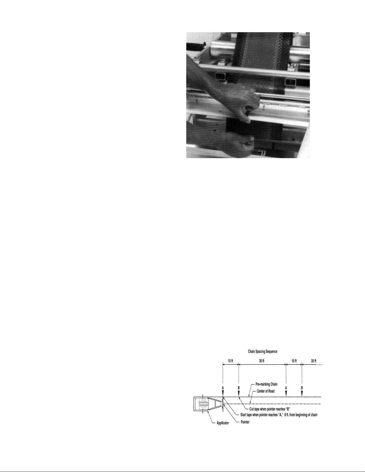
Application Techniques (Refer to
Diagram A)
Pre-marking:
Using 200-250 ft. (60-70 m) of light rope, chain or
thin wire cable for a guideline, mark the skip
sequence on the chain to be followed. Example:
A sash chain marked to the proper sequence with
1-inch (2.54 cm) spiral key rings.
Example: For a 10 ft. (3 m) skip line and a 30 ft.
(9 m) space (10-30 sequence):
1) Mark point (A), the beginning of the first skip
line, about 8 feet (2.44 m) from the beginning
of the chain to line up applicator.
2) Measure 10 ft. (3 m) and mark point (B), the
end of the skip line.
3) Measure 30 ft. (9 m) and mark point (A), the
beginning of the next skip line.
4) Repeat steps 2 and 3 throughout the remaining
length of the guideline so that the last mark is
at point (A).
Figure 2
Diagram A
Product Width and Spacing
Several combinations of tape widths and spacing
can be applied using the MMHTA-18. Combinations of solid and skip lines may be applied simutaneously. The 3M™ Manual Highway Tape
Applicator can be used to apply all Stamark and
Scotch-Lane pavement marking tapes at maximum
standard roll lengths. NOTE: If special ordering
tape, the maximum roll diameter cannot exceed 20
inches (50.8cm) if the material is to be applied
with a MMHTA-18. Consult your 3M representitive to determine the availbility of the MMHTA-18
in your area.
Operation
The tape applicator can be operated by one person.
The following application rates are based on
asphalt paver speeds of 25 - 50 ft./min. and a
walking speed of 100 ft./min.
10:30 Skip 750 ft./hr.
15:25 Skip 1125 ft./hr.
Solid Line 1500 ft./hr.
Solid / Skip (NPZ) 2500 ft./hr.
Double Solid 3000 ft./hr.
Overall Average 1000 ft./hr.
NOTE: The application rates shown are intended
as guidelines and may vary with project conditions.
Procedure for Application of Pavement
Markings
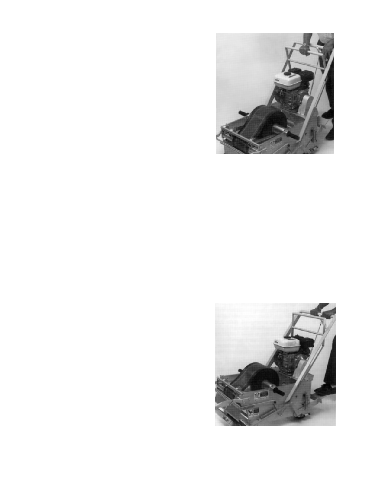
Load the tape and thread it over the 2-inch (5.08
cm) diameter aluminum roll, adhesive side up (See
Figure 2). Feed the tape through the CLAMP to
the CUTTER PLATE. Adjust the GUIDE BARS at
the sides of the tape rolls to hold them securely in
position. The guide bars should be adjusted to
allow the roll to rotate freely, but not move side to
side. Stamark pavement marking tapes can be
ordered with the adhesive side of the tape wound
inward or wound outward. Both types of rolls will
work with the MMHTA-18; however, the tape
wound adhesive side out is recommended. The
tape wound adhesive side out will develop a natural curl that positions it to curve toward the silicone
applicator roll as it passes through the cutting
plate.
CAUTION: Do not activate the cutting knife with
the foot pedal while threading tape.
Page 3
3
Figure 3
Pre-Application Preparation
1. Inspect cutting blades, clean and adjust if necessary. See Maintenance.
2. Check all fastening hardware and tighten if
necessary. Do not overtighten. Use self-locking hardware if replacing missing nuts or bolts.
3. Engine pre-operation check. See Maintenance
for maintenance intervals.
A. Oil: Use Honda 4-stroke oil, or equivalent
detergent, premium quality motor oil. SAE
10W/30 is recommended for general all-temperature use.
- Remove the oil filler cap/dipstick and wipe clean.
- Insert the dipstick into the oil filler neck, but do
not screw it in.
- If oil level is low, fill to the top of the oil filler
neck with recommended oil.
B. Air Cleaner: Check the air cleaner elements to
be sure they are clean and in good condition.
Clean or replace the elements if necessary.
C. Fuel: Remove the f iller cap and check the fuel
level. Refill the tank if the fuel level is low. Do
not f ill above the shoulder of the fuel strainer.
Tape Application
1. Determine where the first skip or long line
starts by measuring from the last existing skip
or reference mark and the side of the road.
Offset the premarked chain at least 12 inches
(30 cm) from the center of where the new
markings will be applied.
2. Lay the guideline out and adjust the pointer to
the side of the applicator. Position the applicator even with the pre-marking chain, and position the pointer to the side as shown.
3. To star t application, position the right hand in
the center of the clamp handle when moving
the handle forward to aid in keeping the applicator moving in a straight line when star ting
tape application (See Figure 3). Slowly move
the clamp handle forward while squeezing the
clutch lever to move the applicator forward at
about the same speed. After tape application
has begun, immediately release the clamp handle to allow the tape to move freely. As the
tape applicator is moved forward, start the
pavement marking each time the pointer passes
over “A,” and cut the pavement marking each
time the pointer passes over “B.”
4. When the last mark on the guideline is reached,
start the next pavement marking, stop the
machine and again lay the guideline out in
front of the pointer.
Tape Cutting
Release the clutch bar and bring the applicator to a
complete stop over the proper marking. Back-up
1/2 inch (1.27 cm) before cutting the tape and
release the foot pedal slowly. Do not attempt to
cut the tape while moving. Cutting the tape in
motion will stretch and tear the tape, causing the
next line to start off center.
When cutting a single line or both lines of a double line, depress either the right or left foot pedal
to the lowest position (See Figure 4).
When cutting a single line while applying a double
line, depress the corresponding foot pedal.
Depressing the foot pedal too far will cut both
markings.
Figure 4
Page 4

4
Tamping
When inlaying pavement markings in new asphalt
concrete surfaces, tamp the markings during the
f inal compaction (finishing roller) of the mat.
After application of markings on existing surfaces,
tamp the tape thoroughly with the 3M™ Roller
Tamper Car t (RTC-2) with a minimum 200 lb.
(90 kg) load, or slowly (2-3 mph) drive over the
tape three times with a vehicle tire. The vehicle
must be equipped with a pointing device to aid in
keeping the vehicle on the tape, making three
passes forward over the tape. Use a vehicle tire on
long line markings only. Do not attempt to tamp
intersection markings with a vehicle tire.
Tamping is most important!
When using the RTC-2 Roller Tamper Cart with
200 lbs. (90 kg.) of weight:
• Do not twist or turn the tamping device on the
tape.
• Make three passes back and forth over each part
of the tape.
• When tamping symbols, start in the center and
work to the outside edges.
• Make sure all edges are fir mly adhered.
• Open road to traffic as soon as tamping is
complete.
Maintenance
Keep All Fasteners Tight
Lubrication:
All the pivot points and sliding areas
should be kept lubricated with light oil penetrant
such as 3M™ Five-Way Penetrant or similar penetrants such as WD-40.
Cleaning: The r ubber application roller wheels
and cutting mechanism must be kept clean. 3M™
Citrus Base Industrial Cleaner or any natural citrus
based cleaner may be used on the wheels and
knives. Solvents may be used occasionally for diff icult cleaning problems. A spray bottle of cleaner
is useful to prevent asphalt buildup on the wheels
and adhesive buildup on the knives during operation.
Caution: Do not use solvents or petroleum products on the silicone application roller when working on new, hot asphalt surfaces. A paint scraper or
putty knife should be used to clean the asphalt
buildup from the scraper and cutter mounting bar.
To prevent asphalt buildup around the roller, additional clearance can be provided by loosening the
scraper mounting screws and sliding the scraper
back. Tighten the screws. Second, remove the cutter mounting bar and grind 1/8 inch (3.175 mm)
off the bottom. Replace the bar.
Each Every 50 Every 100
Use Hour Hours
Engine Oil Check Level X X
Change*
Air Cleaner Check X X
Clean*
Spark Plug Clean and X
Readjust
*Service more frequently when used in dusty areas.
Adjustments
The SCRAPER BAR, which is readjusted by the
manufacturer to prevent excess materials from accumulating on the application roller, should be periodically checked for wear and rotated if necessary. The bar should contact the rubber roller
across the full length of the roller.
The KNIVES are readjusted by the manufacturer
to slide across each other with a minimum of friction in a scissors action. Adjustment is needed
when foil construction tapes are not cleanly cut.
Either the STATIONARY KNIFE or the SLIDING
KNIFE may be adjusted (See Figure 5). To adjust
the stationary knife, loosen the mounting screws
slightly. Turn the set screws to bring the cutting
edge down, and retighten the mounting screws.
The same procedure is followed to adjust the sliding knife. Each knife has two cutting edges. The
knives may be removed and new cutting edges
exposed. The knives may be sharpened after the
cutting edges are dull.
Figure 5
Page 5

5
Troubleshooting
Tape Does Not Advance:
1. If the clamp springs have been overly stretched,
there will not be enough tension to advance the
tape. The springs should be replaced.
2. If the GUIDE BARS are too tight to the roll,
the tape will not advance properly. The bars
should be positioned so that the tape can
advance freely but hold the tape from moving
side to side.
3. If the teeth on the clamp are severely worn,
there will not be enough force to advance the
tape. See Replacement Parts or call your 3M
representative.
4. Check to see if the tape releases from itself
properly. There should be no adhesive picking
from the back side of the tape to the topside of
the next layer.
Tape Does Not Cut:
The tape will not cut cleanly if cutting is done
while the applicator is in motion. If the knife edges
are dull or out of alignment, the knives should be
sharpened and adjusted. (See Adjustments.) Clean
adhesive buildup from knives. (See Maintenance.)
Shipping
The MMHTA-18 must have the fuel drained prior
to shipment in an enclosed area. It is recommended to transport the MMHTA-18 using a utility
trailer.
Replacement Parts
The following is a complete listing of available replacement parts for the 18-inch (45.72 cm) wide
Motorized Manual Highway Tape Applicator
(MMHTA-18). When ordering, please note the
“MH-x” number in the right column. A complete
description of all parts included for each order
entry number is provided. Some parts are not
available separately, so take time to find the proper order number that contains all the parts needed.
Alphabetical Listing of Title Items: See the
chart on the following page for a complete listing.
Aluminum Roll Assembly MH-41
Bar Guide Assembly MH-4
Cartridge Bearing MH-56
Clamp Assembly MH-46
Clamp Pivot Shaft MH-47
Clamp Spring (small) MH-61
Clamp Spring (large) MH-10
Clutch Rod Assembly MH-55
Cutter Bar MH-45
Cutter Blade - Top MH-43
Cutter Blade - Bottom MH-44
Cutter Spring Assembly MH-14
Drive Axle Assembly MH-51
Drive V-Belt MH-57
Engine - 5.5 HP Honda MH-59
Guide Clamp (front) MH-12
Guide Clamp (rear) MH-13
Idler Pulley Assembly MH-54
Pointer MH-25
Pointer Assembly MH-39
Pointer Clamp Assembly MH-18
Power Transfer Shaft Assembly MH-53
Roller Chain Assembly MH-58
Side Frame Connecting Rod MH-49
Silicone Rubber Roll MH-50
Stock Roll Shaft MH-40
Stop Clamp MH-20
Swivel Caster Assembly MH-16
Tape Guide MH-11
Vibration Mount MH-60
Wheel Assembly MH-52
NOTE:After locating the proper replacement
part, check the following table to see a complete
listing of hardware included with each assembly.
Page 6

6
Code Description
MH-4 Bar Guide Assembly
(2) Screw, Soc. Hd. Cap, Stl, Zinc
Plt., 1/4-20 x 1-1/4
(1) Screw, Soc. Hd. Cap, Stl., Zinc
Plt., Loc-Wel, 1/4-20 x 5/8
MH-10 Clamp Spring (large) Assembly
(1) Screw, Hex Hd. Cap, Stl., Zinc
Plate 1/4-20 x 7/8 Lg.
(1) Nut, Hex, Stl., Zinc Plt., 14-20
MH-11 Tape Guide
(1) Tape Guide
MH-12 Guide Clamp (front) Assembly
(1) Wing Nut, Stl., Zinc Plt., 3/8-16
MH-13 Guide Clamp (rear) Assembly
(1) Wing Nut, Stl., Zinc Plt. 3/8-16
MH-14 Cutter Spring Assembly
(2) Screw, Hex Hd. Cap, Stl., Zinc
Plt., 1/4-20 x 3/4 Lg.
(2) Nut, Hex, Stl., Zinc Plt., 1/4-20
MH-16 Swivel Caster Assembly
(4) Screw, Hex Hd. Cap, Stl., Zinc
Plt., 1/4-20 x 3/4 Lg.
(4) Nut, Hex, Stl., Zinc Plt. 1/4-20
(4) Lockwasher, Stl., Zinc Plt., 1/4
MH-18 Pointer Clamp Assembly
(1) Pointer Clamp
(2) L-Screw
MH-20 Stop Clamp
(2) Stop Clamp
MH-25 Pointer
(1) Pointer
(2) Pointer Clamp
(4) L-Screw
MH-39 Pointer Assembly
(1) Pointer Frame
(1) Pointer
(2) Pointer Clamp
(1) Pointer Pin
(4) L- Screw
(1) Swivel Caster
(4) Cap Screw, Hex. Hd., Stl., Zinc
Plt., 1/4-20 x 3/4 Lg.
(4) Nut, Hex., Stl. Zinc Plt., 1/4-20
(4) Washer, Lock-Stl., Zinc Plt. 1/4
(1) Hitch Pin Clip, Stl., Zinc Plt.,
.093 Wire x 1-3/4 Lg.
MH-40 Stock Shaft Roll
(1) Stock Roll shaft
MH-41 Aluminum Roll Assembly
(1) 2 inch (5.08cm) Diameter Roll
(2) Flanged Bearing-Oilite No.
FF-1014
(2) Set Screw-Hex. Soc., Cup Point
1/4-20 x 3/8
Code Description
MH-43 Cutting Blade - Top
(9) Cap Screw-Hex. Soc., Stl., Zinc
Plt. #10-24 x 5/16 Lg Loc-Wel
(10) Set Screw-Hex. Soc.,
CupPoint Zinc Plt., #10-24 x 3/8
Lg. Loc-Wel
MH-44 Cutting Blade - Bottom
(9) Cap Screw-Hex. Soc., Stl., Zinc
Plt. #10-24 x 1/2 Lg. Loc-Wel
(8) Set Screw-Hex. Soc., CupPoint
Zinc Plt., #10-24 x 3/8 Lg. LocWel
MH-45 Cutting Bar
(1) Cutting Bar
MH-46 Clamp Assembly
(1) Windscreen
(2) Cap Screw-Hex. Soc., Stl., Zinc
Plt., #10-24 x 5/16 Lg. Loc-Wel
MH-47 Clamp Pivot Shaft Assembly
(2) Screw, Soc. Hd. Cap, Loc-Wel,
Stl., Zinc Plt., 1/4-20 x 3/4 Lg.
MH-49 Side Frame Connecting Rod
(2) Cap Screw-Hex. Hd., Stl., Zinc
Plt. 1/2-13 x 1 Lg.
MH-50 Silicone Rubber Covered Roll
Assembly
(3) Roll, Silicone Rubber Covered 4 in. dia.
(6) Bearing, Flange Series - General
#32662-88
(2) Set Screw, Hex. Soc., Cup Point
Zinc Plt. 1/4-20 x 3/8
MH-51 Drive Axle Assembly
(1) Axle
(4) Washers
(1) Key - 3/16" Sq.l X 1.2 Long
(1) Sprocket, 30 Tooth 3/4" Bore
Boston #SSC75
(1) Collar, Set Screw - 3/4" Dia.
Boston #SSC75
(4) Inner Race, Torrington #IR-1224
MH-52 Wheel Assembl y
(1) Wheel - Modified
(1) Spacer - Wheel Bearing
(2) Bearing, Torrington #JHTT-1614
(2) Bearing - Clutch Torrington
#RC-162110
MH-53 Power Transfer Shaft Assembly
(1) Shaft - Power Transfer
(2) Bearing - Roller Torrington
#JTT-1410
MH-54 Idler Pulley Assembly
(1) Pulley - Idler
(2) Pulley - Bearing Fafnir
#FS-3-KDD
(1) E-Ring - 3/8 Dia. Shaft, Truarc
#5133-37
Page 7

7
Code Description
MH-55 Clutch Rod Assembly
(1) Rod - Clutch (Upper)
(1) Rod - Clutch (Lower)
(1) Turn Buckle - McMaster
#30125T4
(2) Clevis - Rod - Bimba
#D-10139-A
(3) Nut, Lock, Grade 2 Toplock 1/420 Unc, Stl, Zinc Plt.
MH-56 Cartridge Bearing
(1) Cartridge Bearing, Fafnir
RCJC-3/4
MH-57 Drive V-Belt
(1) V-Belt, Gpl Premium, Dayco
#L430
MH-58 Roller Chain Assembly
(1) Chain, Roller, ANSI #40 1/2 in.
Pitch, 2 ft. Long
(1) Chain Link #40, +in. Pitch
Code Description
MH-59 Engine - 5.5 HP Honda
Engine 5.5 HP, 6:1 Reduction,
Exhaust Deflector, Honda
#GX160-K1HX2
MH-60 Vibration Mount
Vibration Mount, 70 Durometer,
McMaster #64875K64
MH-61 Clamp Spring (small) Assembly
(2) Lee Spring #LE-037D-9-MW
(4) Screw, Bottom Hd. Cap, Stl.,
Zinc Plt. 1/4-20 x 3/4 Lg.
(2) Screw, Soc. Hd. Cap, Stl., Zinc
Plt., #10-24 x 1/2 Lg.
(1) Blue Line Print of Drawing
For fur ther information, contact: 3M Traff ic
Control Materials Division,1-800-553-1380.
Follow instructions to reach Technical Service
for Pavement Markings. In Canada call 1-519452-6201.
Page 8

8
Page 9

9
Page 10

3M assumes no responsibility for any injury, loss or damage arising out of the use of a product that is not of our manufacture.
Where reference is made in literature to a commercially available product, made by another manufacturer, it shall be the user’s
responsibility to ascertain the precautionary measures for its use outlined by the manufacturer.
Important Notice
All statements, technical information and recommendations contained herein are based on tests we believe to be reliable, but the
accuracy or completeness thereof is not guaranteed, and the following is made in lieu of all warranties, express or implied.
Seller’s and manufacturer’s only obligation shall be to replace such quantity of the product proved to be defective. Neither seller nor
manufacturer shall be liable for any injury, loss or damage, direct or consequential, arising out of the use of or the inability to use the
product. Before using, user shall determine the suitability of the product for his/her intended use, and user assumes all risk and
liability whatsoever in connection therewith.
Statements or recommendations not contained herein shall have no force or effect unless in an agreement signed by officers of seller
and manufacturer.
3
Traffic Control Materials Division
3M Center, Building 225-5S-08 3M Canada 3M Mexico, S.A. de C.V.
P.O. Box 33225 P.O. Box 5757 Apartado Postal 14-139 Printed on recycled paper
St. Paul, MN 55133-3225 London, Ontario N6A 4T1 Mexico, D.F. 07070 75-0300-1799-2
 Loading...