

Page 1

3M Touch Systems Technical Note
Product: MicroTouch™ CT150 Monitor Industrial Bezel – Installation Instructions
MicroTouch
™
CT150 15" LCD Monitor – Industrial
Mount Bezel Installation
Overview
The “Industrial Mount Bezel” is a user-installable bezel option for the CT150 15" LCD Chassis
monitor. When properly installed, the industrial bezel creates an IP 66 level seal between the bezel
and the touch screen on the display, providing ingress protection against dry and wet contaminants.
When properly integrated, both the bezel-to-touch screen seal (inner gasket) and the bezel-to-cabinet
seal (outer gasket) will provide an IP66 level of protection. This seal has been tested to IP66 sealing
standards by an independent laboratory. However, due to 3M’s inability to control the enclosure
surface quality and finish against which the outer gasket will seal, we cannot guarantee an IP66 level
of sealing in this location. Each integration is unique and one needs to ensure that the housing surface
against which the outer gasket will seal is reasonably smooth, planar and free from deep scratches
which radiate across the sealing band. The gasket used in this location is relatively soft and
compliant, and therefore is forgiving of minor surface irregularities. However, it is always preferred
to have the surface as smooth and planar as possible around the entire perimeter of the bezel to ensure
high seal integrity, as well as preventing torsion of the bezel (forcing it out of plane) during
installation. Generally, a surface finish comparable to that of an average counter top laminate is an
ideal sealing surface for this type of gasket.
Industrial Mount Bezel Part Number: 29368 - 15"
Can be used on monitor part number(s): 11-71315-225-xx or 11-71315-227-xx
Document #33148 3M Touch Systems Inc. Proprietary Information © 2006 3M. All Rights Reserved. Page 1
Page 2
3M Touch Systems Technical Note
Product: MicroTouch™ CT150 Monitor Industrial Bezel – Installation Instructions
Bezel Installation Instructions
1. Place a soft, clean towel on a solid, flat work surface to prepare for the bezel installation.
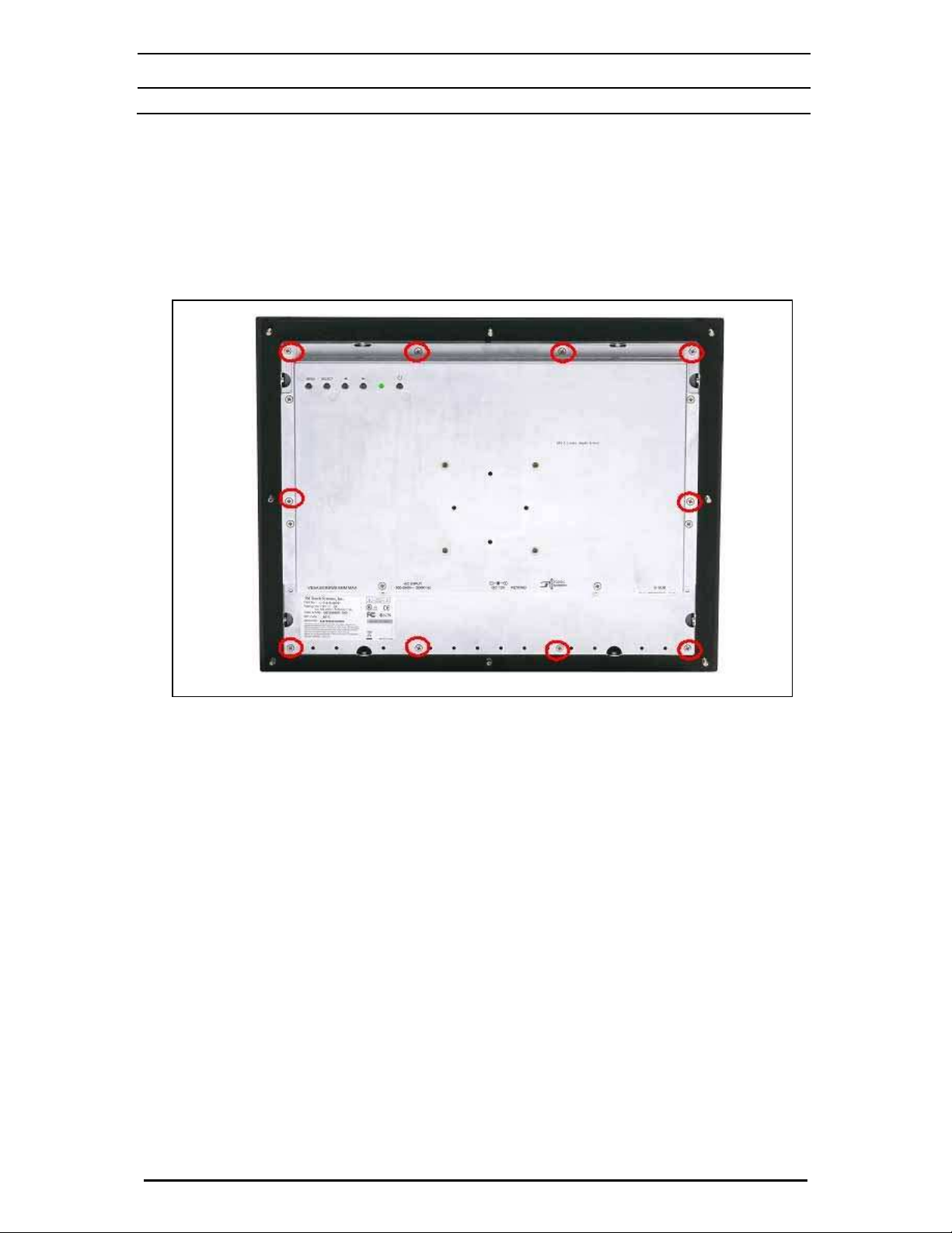
2. If your CT150 monitor has another bezel on it, you must first remove the existing bezel from the
monitor prior to installation of the industrial bezel. If necessary: Place the monitor face down on
the protected work surface. Remove the bezel affixing screws from the back of the unit (screw
locations shown in figure 1 below) and gently separate the bezel from the display.
Figure 1 – Bezel screw locations
3. Unpack the industrial mount bezel from its box and plastic bag. You should note that there are
two gaskets mounted to the bezel at the factory. The inner gasket provides the ingress protection
seal between the bezel and touch screen. The outer gasket is installed to provide an ingress
protection seal between the larger diameter of the bezel and enclosure into which the monitor will
be mounted.
Document #33148 3M Touch Systems Inc. Proprietary Information © 2006 3M. All Rights Reserved. Page 2
Page 3

3M Touch Systems Technical Note
Product: MicroTouch™ CT150 Monitor Industrial Bezel – Installation Instructions
4. Inspect the bezel assembly. Confirm the presence and integrity of both gaskets. Confirm the
presence and integrity of 8 threaded studs on the outside diameter of the bezel. Confirm the
presence and integrity of 10ea.- I.D. threaded extensions on the inside diameter of the bezel. See
Figure 2.
Figure 2 – Part identification
5. The bezel is designed such that the frame piece immediately outside of the I.D threaded
extensions pilots on the outside of the monitor frame. Place the bezel “face down” on the
protected work surface with the studs and threaded extensions facing you. Loose-fit the bezel
onto the CT150 monitor by carefully lowering the chassis monitor into the bezel frame. Be
careful not to drop the monitor onto the bezel as damage to the monitor may result.
Note: There is no top or bottom to the bezel - either orientation is correct.
Document #33148 3M Touch Systems Inc. Proprietary Information © 2006 3M. All Rights Reserved. Page 3
Page 4

3M Touch Systems Technical Note
Product: MicroTouch™ CT150 Monitor Industrial Bezel – Installation Instructions
6. Loosely secure the bezel with the ten M3 x 12mm phillips screws provided as shown by the red
circles in the figure below. Install the four corner screws first to ensure that the bezel is seated
uniformly. Then install the six remaining screws. Install all of these screws only until you begin
to feel the resistance of the shoulder of the screw seating against its mating surface on the monitor
case.
7. Torque the screws. All bezel affixment screws need to be tightened to a torque of 7 in/lbs to
effect a proper seal. Utilize and repeat an alternating cross pattern as shown in Figure 3 until the
7 in/lb. torque rating is achieved at all screw locations. Do not over tighten the screws or you
may damage the chassis or the LCD display.
Figure 3 – Screw Tightening Sequence
8. The eight studs on the outside of the bezel require an M5 nut. Due to the array of unique
installation possibilities, these are not provided by 3M.
Document #33148 3M Touch Systems Inc. Proprietary Information © 2006 3M. All Rights Reserved. Page 4
Page 5

3M Touch Systems Technical Note
Product: MicroTouch™ CT150 Monitor Industrial Bezel – Installation Instructions
3M Touch Systems
3M Display & Graphics
300 Griffin Brook Park Drive
Methuen, MA 01844
U.S.A.
1-866-407-6666
www.3M.com/touch
Document #33148 11/06
MicroTouch, the MicroTouch logo, and ClearTek are either registered trademarks or trademarks of 3M in the United States and/or other
countries.
RoHS Directive compliant: In accordance with European Directive 2002/95/EC, "RoHS Directive compliant" means that the product or
part does not contain any of the following substances in excess of the following maximum concentration values in any homogeneous
material, unless the substance is in an application that is exempt under RoHS: (a) 0.1% (by weight) for lead, mercury, hexavalent chromium,
polybrominated biphenyls or polybrominated diphenyl ethers; or (b) 0.01% (by weight) for cadmium. Unless otherwise stated by 3M in
writing, this information represents 3M’s knowledge and belief based on information provided by third party suppliers to 3M. (9/06)
NOTICE: Given the variety of factors that can affect the use and performance of a 3M Touch Systems Product (the “Product”), including
that solid state equipment has operation characteristics different from electro mechanical equipment, some of which factors are uniquely
within User’s knowledge and control, it is essential that User evaluate the 3M Touch Systems Product and software to determine whether it
is suitable for User’s particular purpose and suitable for User's method of application. 3M Touch Systems’ statements, engineering/technical
information, and recommendations are provided for User’s convenience, but their accuracy or completeness is not warranted. 3M Touch
Systems products and software are not specifically designed for use in medical devices as defined by United States federal law. 3M Touch
Systems products and software should not be used in such applications without 3M Touch Systems’ express written consent. User should
contact its sales representative if User’s opportunity involves a medical device application.
IMPORTANT NOTICE TO PURCHASER: Specifications are subject to change without notice. These 3M Touch Systems’ Products
and software are warranted to meet their published specifications from the date of shipment and for the period stated in the specification. 3M
Touch Systems makes no additional warranties, express or implied, including but not limited to any implied warranties of merchantability or
fitness for a particular purpose. User is responsible for determining whether the 3M Touch Systems Products and software are fit for User's
particular purpose and suitable for its method of production, including intellectual property liability for User's application. If the Product,
software or software media is proven not to have met 3M Touch Systems’ warranty, then 3M Touch Systems’ sole obligation and User's and
Purchaser’s exclusive remedy, will be, at 3M Touch Systems’ option, to repair or replace that Product quantity or software mediator to
refund its purchase price. 3M Touch Systems has no obligation under 3M Touch Systems’ warranty for any Product, software or software
media that has been modified or damaged through misuse, accident, neglect, or subsequent manufacturing operations or assemblies by
anyone other than 3M Touch Systems. 3M Touch Systems shall not be liable in any action against it in any way related to the Products or
software for any loss or damages, whether non-specified direct, indirect, special, incidental or consequential
(including downtime, loss of profits or goodwill) regardless of the legal theory asserted. (7/02)
Document #33148 3M Touch Systems Inc. Proprietary Information © 2006 3M. All Rights Reserved. Page 5
 Loading...