

Page 1
|
Table
of
Contents
Model
3000
and
Micro
3100
Warespey & Service
Section
1.1
1.2
1.3
Section
"Table
Section
3.1
3.2
3.3
Front
1:
General
3M
Infusion
Micro
3100
Epidural
Precautions.
Installation......................
1.
2.
Operational
Controls & Indicators.
1.
Options
Administration.
2:
Specifications
2olocoocccocacanonocconenconoronosnorenronenensornoroerraonor
3:
Installation & Operation
AC
Power
Portable
Panel
Controls
Message
Key..
Policy.
Description
Therapy
System
Models
Description.
Connection...
Operation & M
Description.
€:
Indicators
Display.
Occlusion
Primary
Secondary
2.
3.
Rate
Volume
“Number
“+
(Decimal)
>
Run
Hold
。
*
4.
Battery
5.
Inside
Pump
1.
2.
Back
Panel
1,
2.
Photo
Pumping
SY
Door
Cassette
Safety
Alarm
Computer
Keypad
Alarm
Setting
Key & Indicator...
Key & Indica
Sensor...
Key & Numeric
to
Keys
Key & Indicator..
Key
dz
(Charge)
Indicator.........
Latch
Door
Clip
Controls
Volume
το
Indicat
be
Infused
(0-9).
Key......
Indicator.
у.
(Handle)...
Loading
Retention
Port........
Key & Numeric
Indicator.
Pins...
Control.
바
Button.
Display...
Slot.
Key.
3000
&
roer
Display.
rosrness
2-2
.
1
te
ča
Pe
の
の
や
の
の
ыы
Un
a
CA
CA
CA
いい
ふい
ar Ad
Alerts:
1.
2.
3.
4.
Alarms:
5.
6.
7.
8.
5,
10.
11.
12.
13.
14.
Table
3-1
3.7
Options.
2.
Time
3.
Message
4.
Battery
5.
Quick
6.
Rate
Biomedical
1.
2.
5.
6.
7.
8
.
8.
9.
10.
11,
КУО
Low
Rate
Secondary/was
Pump
System
Occlusion/below
Air
Door
On
Battery
Close
Loading
Summary
System
Snapshot
Pump
Volume
Charge
On
Pressure
Baud
Language
Battery
Display
mi
battery/Plug
change/not
needs/service.
in
open...
Hold...
clamp!/Load
Remaining
Test
rate
Taper
Time.
Rate
/this
in
completed.
set.
check/Tum
pump...
cassette..........
too
low/Plug
problem/Check
of
Alarm
Display
Special
History
Display
Light
Optional
Change
Optional
Warning
Screen-a..
Infused,
History
(Calibrate
Use
Model
Optional
Function........
and
Display - Hours
Loading
Display - AC,
Selection...
Selection.
Display.
Ni
infusion.
cord...
off
then
in
Safety
Conditions.
Optional
Function................
Punction..
error
у...
Mode)
on.
cord.
Cl
tubing
.
optional
Function
Function.
Function.
code
Cycles..................
Display.
display.
of
operation,
Charge,
3-14
-14
3-14
-14
-14
-14
….
~
3-29
Battery
3-29
"3.29
3-29
3-30
Page 2
-4.13
Pole
Clamp.........
4.14
‘Modular
Electronic
4.15
4.16
4.17
4.18
4.19
4.20
4.21
4.22
Circuit
i
System
Power..............
Interface
Interconnection
Detailed
CPU/Power
4.22.1
4:22.2
Control...
System
Motor
System.
Description.
designs.
(017
Table
4-1
Miscellaneous
Control
4.22.3
Nonvolatile
4.22.4
Audio
4.22.5
Power
-
4.22.6
4.23
4.24
425
Section
5.1
Service
5.2
Materials
5.3
Recommended
5.4
Recommended
5.5
Special
Periodic
5.6
Cleaning...........….….
‘Table
5.7
Recommended
1
2
3.
4.
5.
6.
7
8.
Power
VO
Board...............
4.23.1
Motor
4.23.2
Switch
4.23.3
Battery
Display
4.24.1
4.24.2
4.24.3
4.244
4.24.5
RS232
5-1
Board...
Keypad
Analog
7-Segment
4.24.3.1
LCD
Pressure
Interface.
5:
Maintenance
Information.
Return
Tools.....
Maintenanc
Recommendation
on
3M
Record
Audio
Power
LCD
pump
Alarm
Up & Self
Contrast & LED
/
Descriptions
Summary.
Supply
Control
Monitor
Uni
Microprocessor
49
VO
Signals
Unit
Circuit..
Supply.
Control.
Control.
Sensor
Charger.
(U15)
Memory.
Interface.
Unit...
Sensor
Display
Unit
Plate
Procedure.
Test
Troubleshooting
Pump'Exterior........................vuie
12-Month
Test.....
Unit...
Display
иен
Position
Equipment...
for
history.
Test...
on
System
Unit...
Control
Functional
Unit.
Sensor.
eee
Cleaning
Brightness.
Agents
and
411
4-11
4-12
4-12
4-13
4-13
4-13
4-14
4-14
4-14
4-15
4-15
4-15
4-15
4-16
so
5-2
5-2
52
5-2
5-3
34
54
5-4
5.8
Table
5-9
5.10Calibration
Table
Section
6.1
Table
Table
Table
Table
Table
Table
Table
Table
Section
Section
.
8.1.
Section
9.
Valve
10.
Pressure
Point.
11.
Check
12.
Motor
13.
Empty
14.
Air
15.
KVO
Accuracy.
Integrity
Occlusion
Torque
Bag
Detect
Aiam,
Test...
Plate
Position
Test....
Check..
Alarm...
Volumetric
Settings.
Troubleshooting.
5-2
Troubleshoo!
Disassembly
1.
Battery
2.
AC
Fuse...
3.
Front
Housing
4.
Door
Assembly...
5.
CPU/Power
6.
I/O
Board
7.
‘Membrane
8.
Pump
9.
10.
11.
12.
1.
Power
2.5.00
3.
Low
A.
B.
4.
Cam
5.
Occlusion
6.
Empty
5-3
Mechanical
6-1
6-2
6-3
6-4
6-5
6-6
6-7 1/0
6-8
Sample
Assembly.
Motor
Assembly
Cassette
Safety
Clip
Door
Switch...
Supply
VDC
Battery
Low
Dead
Housing
Bag
Recommended
6:
Parts
Pump
Swingarm
Front/Rear
Pole
Display
Power
PWB
RS232
7:
Electrical
8:
Wavé
Wave
9:
Message
and
Reassembly
Removal.
Housing...
Supply
AssembiY....................
Switch
Mechanism.
Board
Replacement.
and
Vo
5
Voltage
Check...
Alarm
Battery
Battery
Switch
Alarm
Contacts
Lists
and
Structural
Assembly
Assembly
Clamp
PWB.......................
Supply
Parts...
Serial
Diagrams
Form
Forms...
Display,Screens
Check.
Calibration
Alarm...
Alarm..
Adjustment..
Adjustment.....
Adjustment.
Spare
and
Diagrams
Parts...
Housing
Assembly
CPU
Interface
Diagrams
Sensor
Breakopen
and
Rate
.
Assembly.
Check...
Parts
List..
Parts..
Parts...
Assembly
Parts
PWB
Parts..
ttt
PWB
Parts.
mom
©.
_
i
5-5
ve
3-5
5-5
5-7
5-7
5-7
-7
pinta
ae
o
oo
No
o%
>
Tables & Charts
2-1
Pump
3-1
Gü
mary © of
5-1
ュー
TBC-2
Recommendations
-
Pump
-2:
Troubleshooting
Recommended
(3/94)
Specifications.
Alarm
Conditions..
for
Cleaning
Exteribi!.............
Guide.
Spare
Parts
List.
。
-
Agents
on
3M
.
„5-9
.
-
Figures
3-2
Front
3-3
Back
4-1
Linkage
4-2
Cassette
5-1
Functional
5-2
Battery & AC
Housing
7053
5-4
Door
Pump
we
ge
Pant « Door.
Panel
Controls.
Systém/Safety
Housing & Doo
and
Accuracy
Fuse
Disassembly...
Disassembly
Assembly
Clip
Switc
Check...
Removal,
ο.
Removal..
Front/Rear
56.
\
°
3
Page 3
や
し:
mí
5-5
Motor
Assembly
5-6
Cassette
Disassembly...
5-7
Door
Switch
5-8
16.5
VDC
pump
5-9
5-10
5-11
5-12
5-13
5-14
5-15
6-1
turned
11.8
VDC
and
pump
13.8
pump
5.00
A
Schematic
set-up.
turned
Cam
Occlusion
Metering
Pump
Assembly.
μμ
μμυμϱῥ-----
Housing & Safety
Disassembly.
Check.
Check.
turned
VDC
turned
VDC
Power
on.
Switch
Power
on.
12.5
VDC
On...
Check.
Check.
diagram
alarm
cam
Power
OD...
Power
A
of
cord
should
Adjustment...
adjustment
as
Related
Clip
Mechanism
co
app!
cord
cord
low
battery
be
plugged
set-up.
to
Empty
plugged
nent
plugged
alarm
5-16
---
into
AC
and
5-19
into
AC
and
5-20
verification
in
and
pump
…
3-20
Bag
6-2
Swingarm
6-3
Front/Rear
6-4
Pole
6-5A
Display
6-SB
Display
6-6
Power
6-7A
VO
6-7B
YO
6-8
RS232
7-1
Functional
7-2
Power
7-3
Electrical
7-4
Electrical
8-1
Air
8-2
Air
8-3
Motor
8-4
Motor
8-5
Motor
8-6
Empty
8-7
Interrupter
Assembly.
Housing
Clamp
Assembly......
PWB,
PWB,
Suppiy/CPU
PWB,
Side
Board,
Serial
Block
Routing......
Routing.
System
Detect - Emitter,
Detect - Detector,
Drive
Pulses,
Drive
Pulses,
Drive
Pulses,
Bag,
P102
Detector,
Assembly.
Side
1
Side
2
PWB.
1...
Side
2..
Interface
Diagram.
Schematics.
TP3
TP2
TP7
TP7
TP7
Pin
6,
TP4,
on
on
on
YO
on
VO
Board.
on
YO
/O
Board.
I/O
Board.
I/O
Board.
Board...
YO
Board.....
Board..
a
o
Çapa
og
фоном
Ho
wo
Page 4

This
Page
Intentionally
Left
Blank
“TBC-4
6/94)
Page 5
Section
A:
Warranty
Service
&
Information
Model
3000
and
Micro
3100
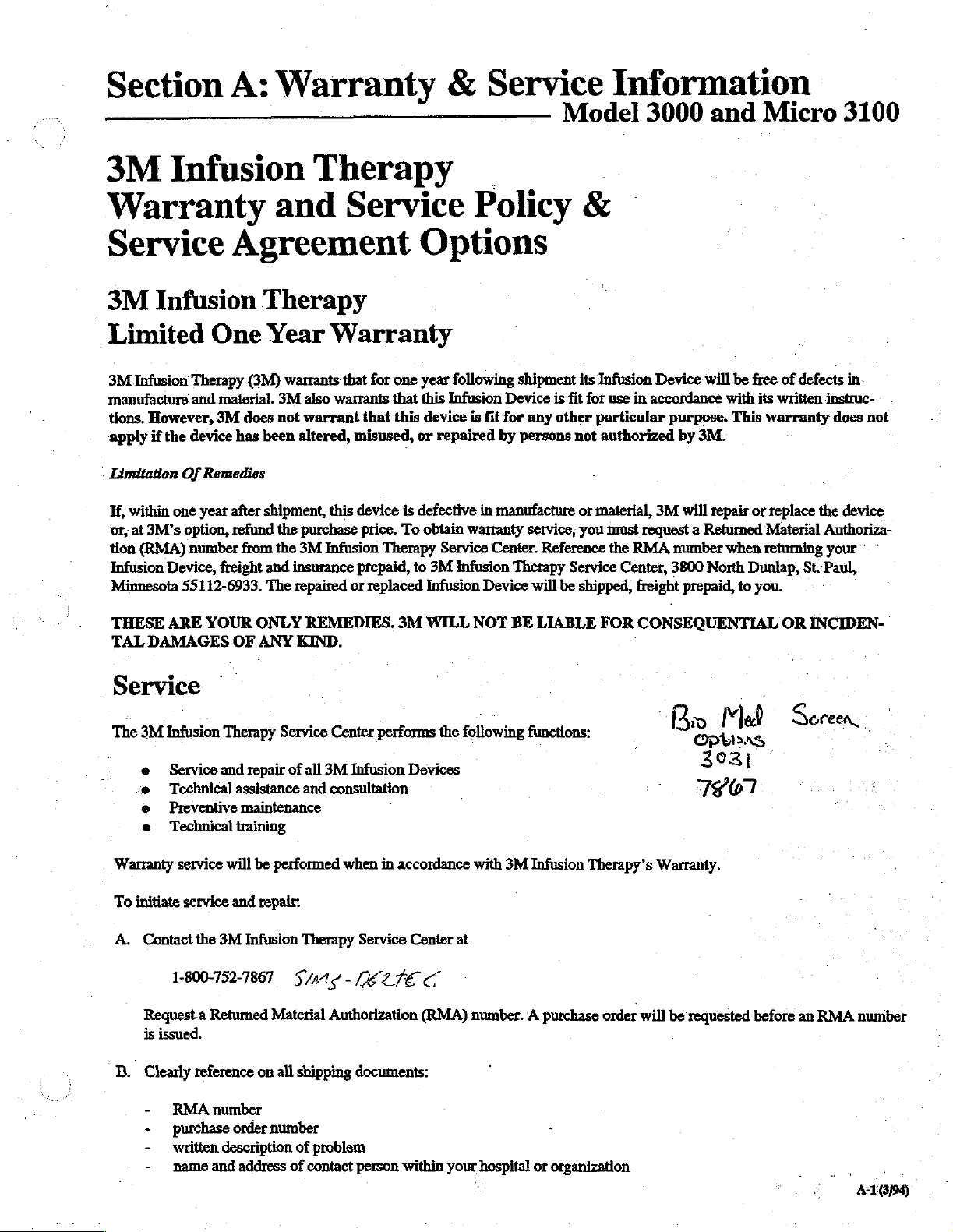
3M
Infusion
Warranty
Service
3M
Limited
manufacture
Infusion
3M
Infusion
tions.
However,
apply
if
the
Limitation
If,
within
or,
at
tion
Infusion
Minnesota
THESE
TAL
Of
one
3M°s
(RMA)
Device,
55112-6933.
ARE
DAMAGES
option,
Agreement
One
Therapy
and
device
year
number
(3M)
material.
3M
does
has
Remedies
after
refund
from
freight
YOUR
OF
Therapy
and
Therapy
Year
3M
not
been
shipment,
the
the
and
The
ONLY
ANY
Warranty
warrants
also
watrants
warrant
altered,
this
purchase
3M
Infusion
insurance
repaired
REMEDIES.
KIND.
Service
Options
that
for
one
year
following
that
this
Infusion
that
this
device
is
misused,
device
price.
prepaid,
or
replaced
or
is
defective
To
obtain
Therapy
to
3M
Infusion
3M
WILL
repaired
warranty
Service
Infusion
|
Policy
shipment
Device
fit
for
any
by
persons
in
manufacture
service,
Center.
Therapy
Device
NOT
will be
BE
&
its
is
fit
other
not
or
you
Reference
Service
shipped,
LIABLE
|
Infusion
for
use
in
particular
authorized
material,
must
request a Returned
the
RMA
Center,
freight
FOR
CONSEQUENTIAL
Device
accordance
3M
will
purpose.
by
3M.
will
repair
number
3800
North
prepaid,
be
free
with
This
or
when
Dunlap,
to
of
defects
its
written
warranty
replace
Material
retuming
you.
OR
in
instruc-
does
the
device
Authoriza-
your
St.Paul,
INCIDEN-
not
Service
The
3M
Infusion
e
Service
e
Technical
e
Preventive
e
Technical
Warranty
To
A.
B.
service
initiate
service
Contact
the
1-800-752-7867
Request a Retumed
is
issued.
Clearly
-
-
-
-
reference
RMA
purchase
written
name
Therapy
and
Service
repair
assistance
maintenance
training
will
be
performed
and
repair:
3M
Infusion
Material
on
all
number
order
number
description
and
address
Center
of
all
3M
Infusion
and
consultation
when
Therapy
Sn
-
Authorization
shipping
of
problem
of
contact
performs
Devices
in
accordance
Service
documents:
person
Center
LTÉE
(RMA)
within
C
the
following
with
at
number. A purchase
your
hospital
functions:
3M
Infusion
or
|
Therapy's
order
organization
Вы
-
Warranty.
will
be
requested
№
o
3931
7461
过
before
Ser
ㆍ.
an
EN
RMA
|
number
41699
Page 6
-
Carefully
C.
Material”
D.
Ship
complete
package
label
the
pump(s),
3M
Infusion
3800
North
St.
Paul,
MN
name
and
the
each
to
freight
Therapy
Dunlap
55112-6933
return
pump(s)
carton
prepaid,
Service
address
in
shipped.
of
original
the
by
traceable
Center
organization.
shipping
means,
carton,
to
other
or
appropriate
-
container,
and
a
affix
“Returned
3M
Service
Loaner”
Any
warranty,
this
pumps
When
the
and
repair
while
chargeable
will
when
calling
will
also
other
than
type
of
shipment
Limited
3M
Infusion
tently
the
service
Infusion
Limitation
If
any
will
correctly
3M’s
(RMA)
Device,
55112-6933.
Therapy
and
in
accordance
center
Device
Of
failure
option,
number
freight
to
refund
The
is
generally
your
pump
is
repairs
not
be
on
be
performed
in
for
the
retumed
normal
requested.
means
Service
(3M)
with
will
be
free
serviced
Remedies
meet
the
Limited
re-perform
from
and
repaired
the
the
purchase
the
3M
insurance
completed
being
repaired, a loaner
pumps
under
without
RMA
number.
freight
prepaid,
of
shipment
Warranty
warrants
in
cases
service
or
replaced
that
industry
from
Infusion
prepaid,
standards.
defects
where a complete
Service
identified,
price.
Therapy
to
Infusion
within 4 working
warranty
customer
all
Warranty
To
3M
or
authorization.
Pumps
under
however a shipping/handling
is
requested
service
in
obtain
and
3M
manufacture
Policy
repair
warranty
Service
Infusion
Device
days
must
be
requested
contract,
also
or
or
warranty
by
the
repair
performed
warrants
or
material.
overhaul
appears
repiace
service,
Center.
Therapy
will
be
shipped,
upon
repairs
If
an
or
customer,
for a period
has
within
defective
Reference
Service
receipt
when
estimated
“estimate
contract
not
you
are
charge
an
additional
by
the
This
warranty
been
ninety
parts
must
the
Center,
freight
by
the
service
calling
to
exceed
is
required
returned
will
service
of
ninety
performed.
(90)
provided,
request a Returned
RMA
number
3800
prepaid,
in
for the
freight
be
added
charge
center
(90)
covers
days
replace
North
to
you.
center.
$150.00
before
days
following
when
Dunlap,
If
you
RMA
number.
on
work
prepaid.
to
the
repair/charge
is
assessed
will
be
performed compe-
that
only
that
service
the
Infusion
Material
returning
St.
need a “Service
pumps
out
of
is
performed”
Out
of
warranty
invoice.
depending
parts
furnished
portion
Paul,
of
the
or
repair,
Device
Authorization
your
Infusion
Minnesota
state
upon
by
3M
or,
at
THESE
TAL
Service
Contact
ARE
DAMAGES
Device
:
Service
Technical
Preventive
Service
Loaners
the
3M
YOUR
Offerings
Training
Assistance
Maintenance
Atena
ONLY
OF
ANY
Seminars
Maintenance
Agreements
Infusion
Therapy
REMEDIES.
KIND.
Agreements
Service
3M
Center
WILL
NOT
BE
at
1-800-752-7867
SMS
BELTE
LIABLE
for
details.
C
FOR
CONSEQUENTIAL
OR
INCIDEN-
Page 7
Section
1:
General
Description
Model
3000
and
Micro
3100
1.1
3M
Infusion
Models
3100
The
3M
Modular
3000
and
Micro
with
various
Infusion
professionals
of
fluid
epidural
programmable
the
dose
The
key
flexible,
may
also
the
pump
Precise
by
the
pumping
patient.
The
pumps
situations.
audible
alert
situations, a separate
indicator
alarm/alert
in
Section
‘The
Model
features.
Change.
life,
total
remaining
continuously
darkened
designed
recordkeeping.
3M
Systems
in
and
medications.
delivery
is
delivered.
component
three-chambered
be
used
due
to
control
mechanical
mechanism
provide
In
alarm
alarm
sounds,
is
displayed,
indicators
3.5
and
3000
These
In
addition,
volume
this
light
rooms. The
to
aid
Therapy
3000 & Micro
System
Infusion
3100
infusion
administration
are
intended
the
intravenous
(see
1.2,
control
over
of
the
for
gravity
their
valveless
over
delivery
manipulation
results
for
monitoring
situations,
and a visual
and
and
3.6.
and
Micro
include
Options
delivered
infusion,
the
display
Biomedical
service
Description
System
pumps
sets.
for
use
and
In
addition,
below).
both
volume
administration
cassette.
administration
design.
rate
and
of
in
smooth
fluid
audible
fluid
delivery
audible
3100
Rate
Tapering
allows
over
several
and a feature
panel
personnel
consists
Both
3M
the
of
alarm
alarm
alarms
also
Special
in
of the
used
in
conjunction
The
3M
Modular
by
trained
intra-arterial
they
pumps
and
administration
volume
flexible
fluid
several
delivery
sounds,
continues.
offer
and
you
infusions,
which
for
easier
troubleshooting
medical
may
be
offer
rate
set
is
the
independent
is
provided
cassette.
delivery
alarm/alert
stops,
is
displayed.
are
fully
several
Quick
to
check
allows
reading
Functions
Model
delivery
used
for
user
at
which
unique,
sets
of
The
to
the
an
In
an
alert
These
explained
optional
Rate
battery
time
you
to
in
are
and
accidentally
for
ambulatory
1.2
The
Model
be
used
Anesthetics
Epidural
term
catheters
delivery
Analgesics
Epidural
with
long-term
e
To
epidural
which
e
Differentiate
epidural
routes
cut
off.
patients.
Epidural
3000
for
epidural
administration
(not
to
exceed
specifically
of
anesthetic
administration
indwelling
prevent
catheters
delivery
infusion
use,
contain
delivery
of
administration.
WARNING
When
delivering
those
medications
Epidural
serious
1.3
administration
patient
injury.
Precautions
DANGER
Never
operate
bathing,
Use
of
the
severe
electric
such conditions,
to
power
this
showering,
pump
shock.
the
pump.
Battery
power
also
Administration
and
Micro
3100
Infusion
administration.
of
anesthetics
96
hours)
indicated
drugs.
of
analgesics
specifically
of
analgesic
of
drugs
do
not
use
IV
injection
the
drugs
specifically
pump
under
only
pump
and
from
those
in | the
of
on
or
otherwise
such
If a pump
DC
(battery)
sites.
other
infusion
AC
conditions
is
with
for
short-term
is
indicated
drugs.
not
indicated
administration
IV
set
being
being
epidural
indicated
drugs
power
immersed
must
power
provides
limited
used
portability
Pumps
may
limited
be
to
short-
indwelling
epidural
to
use only
for
for
sets
used
for
for
other
space,
use
for
epidural
could.result
while
patient
in
liquid.
could
lead
used
under
may
be
also
short-
or
only
use.
in
is
to
used
Both
pumps
delivery
administration
to
primary
attached
patented
connect
infusion
power,
you
to
can
when
used
set,
rate
and
to
an
IV
Modular
up
to 3 pumps
lines
are
or
with
the
continue
be
used
for
secondary
with a checkvalve
switching automatically
volume.
pole
Connection
required.
built-in
infusion
The
using
the
System
together
The
battery.
even
if
pumps
built
for
easy
pumps
Battery
AC
power
(piggyback)
and
in
allows
can
piggyback
from
are
typically
pole
clamp.
you
use
when
be
used
power
fails
secondary
The
to
multiple
on
AC
allows
or
is
DANGER
Place
the
pump
avoid
explosion
DANGER
Electric
Internal
fied,
unplug
shock
servicing
3M
Infusion
AC
away
from
hazard.
hazard
should
Therapy-trained
power
cord
all
exists
if
be
before
flammable
pump
housing
performed
beginning
only
personnel.
anesthetics
is
by
Always
disassembly.
to
opened.
quali-
11699)
Page 8
WARNING
Replace
protect
against
WARNING
The
air
detection
detect
air
used
in
the
side
or
back
fuses
at
the
upright
during
only
fire
system
top
with
fuses
of
hazard.
of
the
of
the
cassette
position.
operation.
Do
same
pumps
when
not
lay
type
are
the
the
and
rating
designed
pump
is
pump
on
to
to
its
WARNING
The
occlusion
pressure
detect
infiltration.
policies
inspect
changes,
detection
in
the
administration
and
procedures,
patient’s
and/or
infusion
other
In
WARNING
Pump
users
should
beginning
of
the
use
pumps
of
any
could
CAUTION
Electrostatically
design
Discharge
printed
CAUTION
Do
not
this
of
the
circuit
autoclave,
pump
pumps.
(ESD)
boards.
in
any
sensitive
must
ethylene
liquid
CAUTION
To
avoid
unnecessary
200
millimeters
pressure
using
the
100
mmHg).
cuff
Low
of
above
Occlusion
sensor
accordance
operator
site
signs
receive
lead
Mercury
inservice
medical
to
injury.
components
Protection
be
provided
oxide
or
pump
Occlusion
the
patient’s
Alarm
detects
set,
for
of
infiltration.
equipment.
(mmHg)
downline
but
is
with
institution’s
must
periodically
swelling,
training
are
against
when
sterilize,
damage
alarms,
when
venipuncture
Setting,
.
back-
not
designed
temperature
prior
Improper
used
Electrostatic
handling
or
submerge
will
occur.
do
not
using
do
not
to
use
in
the
exceed
a
site
when
exceed
to
CAUTION
-
The
Model
cause
this
reason,
autotransfusion
level
flow
below
3000
from
the
the
CAUTION
Federal
the
1-2
(USA)
order
of a physician
(3/94)
and
the
fluid
pumps
system
pump.
law
restricts
Micro
container
should
in
or
3109
not
which
this
other
require
to
the
be
used
blood
is
device
to
licensed
gravity
pump.
collected
use
practitioner.
as
part
by
or
to
For
of
at
on
an
a
Page 9

Section
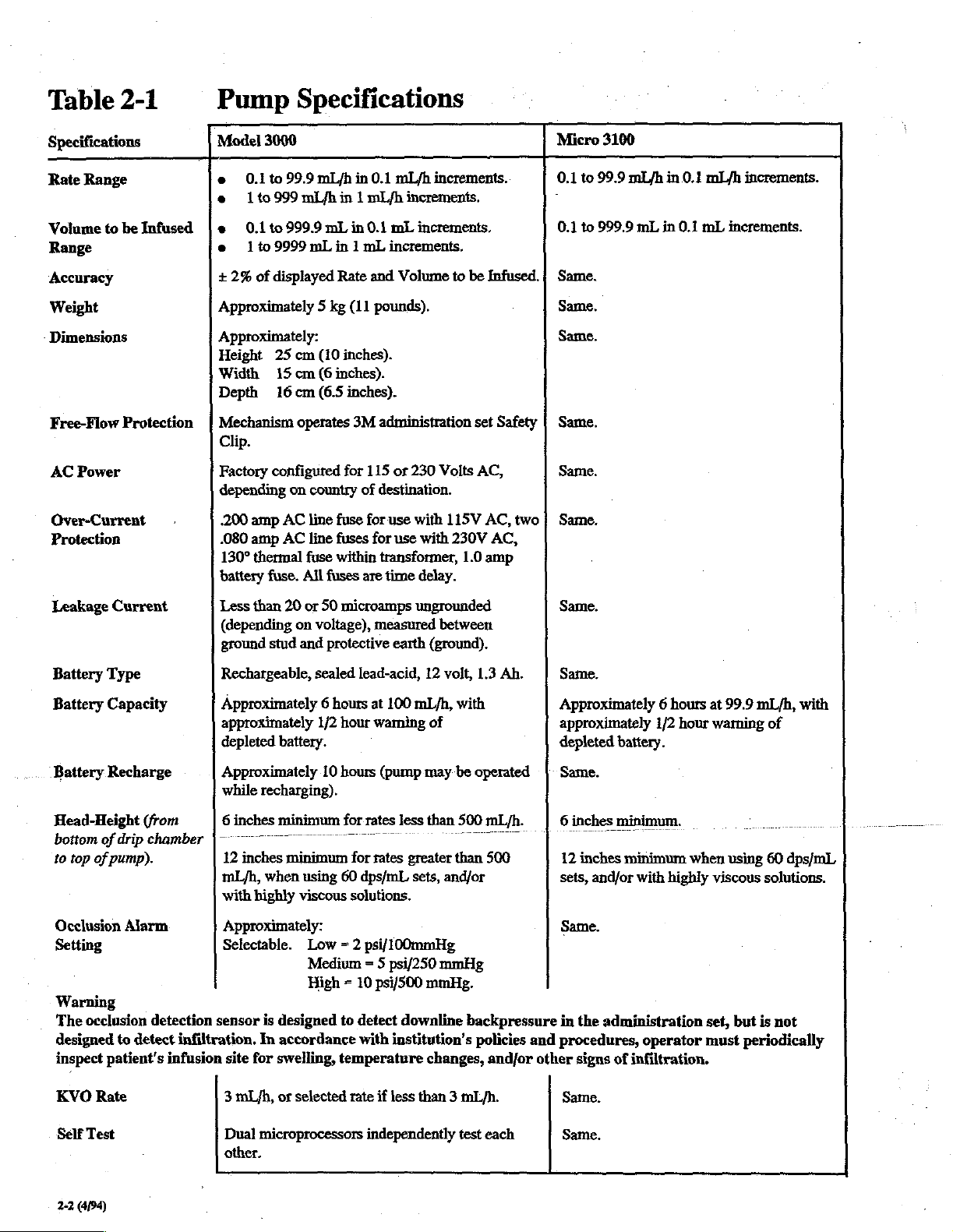
Table
2-1
lists
Model
3000
NOTE
‘All
pump
specifications
notice.
2:
operating
and
Micro
Specifications
and
design
3100
are
specifications
Infusion
subject
Pumps.
to
change
of
the
without
Model
3000
and
Micro
3100
21699)
.
Page 10
1
Table
Specifications
Rate
2-1
Range
Pump
Model
e
0.1
e | [to
9 .
Specifications
3000
to
99.9
mL/h
in
0.1
mL/h
999
mř/h
in | mish
increments.
increments.
Micro
0.1
to
-
3100
99.9
mLyh
in
0.1
mL/h
increments.
Volume
Range
Accuracy
Weight
Dimensions
Free-Flow
AC
Over-Current
Protection
Leakage
Battery
to
Power
Type
be
Infused | +.
Protection | Mechanism
Current
0.1
e
109999
+
2%
of
Approximately 5 kg
Approximately:
Height
Width
Depth
Clip.
Factory
depending
200
amp
.080
amp
130°
thermal
battery
Less
than
(depending
ground
Rechargeable,
to
999.9
mL
mL
displayed
25
cm
(10
15
cm
(6
16cm
(6.5
operates
configured
on
country
AC
line
AC
line
fuse
fuse.
All
fuses
20
or
50
on
voltage),
stud
and
protective
sealed
in
0.1
mL
in 1 mL
Rate
inches).
fuse
fuses
within
microamps
increments.
and
(11
pounds).
inches).
inches).
3M
administration
for
115
or
of
destination.
for
use with
for
use
transformer,
are
time
measured
earth
lead-acid,
increments.
Volume
to
230
Volts
115V
with
230V
delay.
ungrounded
between
(ground).
12
volt,
be
Infused. | Same.
set
Safety | Same.
AC,
AC,
two | Same.
AC,
1.0
amp
1.3
Ah.
0.1
to
Same.
Same.
Same.
Same.
Same.
999.9
mL
in
0.1
mL
increments.
Battery
Battery
Head-Height
bottom
to
Occlusion
Setting
Warning
The
designed
inspect
KVO
Self
Capacity
Recharge
of
drip
top
of
pump).
occlusion
to
patient's
Rate
Test
Alarm
(from
ehamber
detection
detect
infiltration.
infusion
Approximately 6 hours
approximately
depleted
Approximately
while
recharging).
6
inches
|
12
inches
mL/h,
when
with
highly
Approximately:
Selectable.
sensor
is
In
site
for
3
mL/h,
Dual
microprocessors
other.
1/2
battery.
10
minimum
0
minimum
using
viscous
Low
Medium = 5
High = 10
designed
accordance
swelling,
or
selected
at
100
hour
waming
hours
(pump
for
rates
less
for
rates
greater
60
dps/mL
solutions.
= 2
psi/100mmHg
psi/250
psi/500
to
detect
downline
with
institution's
temperature
rate
if
less
independently
mL/h,
with
of
may
be
operated
than
500
than
sets,
and/or
mmHg
mmHg.
backpressure
policies
changes,
than 3 mL/h.
test
mL/h.
500
and/or
each
Approximately 6 hours
approximately
depleted
Same.
6
inches
o
12
inches
sets,
and/or
Same.
1/2
battery.
minimum.
minimum
with
hour
when
highly
at
99.9
waming
using
viscous
in
the
and
procedures,
other
signs
Same.
Same.
administration
operator
of
infiltration.
set,
must
mL/h,
with
of
60
dps/mL
solutions.
but
is
not
periodically
2-2
(4/94)
Page 11
Section
3:
Installation
&
Operation
Model
3000
and
Micro
3100
3.1
1.
The
eguipped
prong,
minimize
wire.
The
manufacture,
safety
tetainer
retainer
or
unreliable.
If
Replacements
order
leakage
important
cords,
connection.
the
connections.
2.
Installation
AC
Power
3M
Model
with a detachable
hospital
leakage
power
cord
testing
is
attached
must
replaced,
the
power
Portable
or
cord
becomes
to
maintain
current.
to
adapter
Always
cord,
System
The
pumps
“operation,
The
infusion
horizontal
tion
set
the
pump
greater
when
solutions).
IV pole
TV pole
portable
are
or
surface,
drip
(12
than
using
Typically,
using
mounting
for
Connection
3000
and
Micro
3100
power
cord,
grade
plug.
The
power
current
is
but
can
of
the
be
reinstalled
ground
should
grounding
Integrity
prevent
plugs,
as
inducing
secured
over
pulling on
to
be
removed
cord
itself
the
and
power
damaged,
be
made
of
electric
or
attempt
hold
the
potentials
the
rear
from
become
cord
by
four
whenever
connections
replace
using
safety
and
the
three-prong
shock.
Do
to
defeat
plug
itself
the
cord
original
Operation & Modular
equipped
in
the
pumps
chamber
inches
500
mL/h,
60
drops/mL
the
patient
with a 12
event
AC
may
be
provided
is
at
may
be
or
on
sets
however,
pole
clamp
and
battery
mobility.
volt
power
fails
operated
the
bottom
least 6 inches
required
both
the
and/or
highly
the
pump
on
the
pump's
operation
Infusion
cord
housing
the
necessary. A cord
the
it
could
while
on
Micro
Pumps
which
has a three-
is
designed
on
the
ground
during
pump
should
screws.
cord
immediately.
acceptable
not
the
when
battery
or
of
above
the
make
The
is
reattached
may
equipment
level
plug
is
use
extension
plug’s
unplugging
damage
for
portable
is
unavailable.
standing
the
administra-
the
3000
with
3100-and
viscous
is
attached
rear
housing.
the
pumps
become
also
ground
top
plug
on
to
are
to
cord
in
of
any
of
rates
3000
an
tip.
3.2
The
central
peripheral
and
microprocessor
alarm
tions.
The
motor
Smooth
forward
is
When
off”
accept a fluid
Completion
Teverse
during
the
upstream
lower
mechanism
The
Clip
and
mechanics
Safety
loading
door
When
lower
when
Operational
Model
3000
system
fail-safe
condition
central
which
running.
you
to
the
the
pumping
fluid
Free-Flow:
(located
the
Clip
is
closed
the
tubing,
the
controller
microprocessors
system
controls
sensors,
microprocessor
is
used
fluid
delivery
rotation
open
load
position.
filled
of
cassette
rotation
mechanical
of
loading
mechanism
pressure
pathway
and
reopens
Prevention
under
on
the
must
the
cassette,
the
door
is
thus
administration
WARNING
To
minimize
always
door,
close
the
the
and
Micro
microprocessor
monitoring
all
and
to
operate
is
accomplished
of
the
pumping
the
door,
the
The
cassette
loading
the
motor
process)
prepares
release,
lower
be
Safety
opened,
preventing
possibility
lower
during
upon
the
cassette
clip
retention
portion
placed
or
the
Clip
the
set
roller
the
System
pump
Description
3100
Infusion
used
for
(CPU2).
user
programmable
interprocessor
also
controls a 4-phase
the
pumping
mechanism
pumping
pistons
when
in
results
as
pressure
on
the
cassette
for
overpressure
reverse
initial
consists
on
slot
of
the
in
the
clip
will
opens
Safety
unrestricted
is
removed
of
unrestricted
clamp
Pumps
(CPU1),
display
rotation
the
control
The
communica-
mechanism.
by
uninterrupted
when
mechanism
are
best
the
load
in
some
(which
is
delivery.
valve
of
forward
of
administration
and
associated
cassette
retention
not
operate.
to
allow
Clip
closes
fluid
from
before
contain
with
two
(CPU3)
central
functions,
stepping
the
pump
“backs
positioned
position.
additional
develops
reduced
rotation.
the
fluid
the
and
To
facilitate
seals
the
pumping
Safety
set)
housing.
slot
when
When
delivery.
over
the
flow
even
pump.
the
The
.
gravity
opening
flow,
the
a
to
the
The
Model
Modular
to 3 pumps
required,
that
pump.
pole)
connecting
Connection
The
any
pump
Only
will
accept
3000
and
for
situations
Modular
can
be a Center,
the
Center
attachment
too
many
Micro
3100
System
which
when
Connector
pump
(pump
of
pumps,
which
are
equipped
allows
multiple
Left,
another
infusion
System
or
Right
which
pump.
could
with
a
connection
lines
is
designed
mounted
is
attached
This
prevents
cause
IV
poles
of
are
so
to
up
IV
to
The
microprocessor
insistent
nine
sages
detail
‘e
.. @ Occlusion
audio
alarm
displayed
in
Section
System
stops
alarm
conditions
during
3.6):
zero
Warning
the
when
is
detected
an
alarm
pump
one
or
condition
and
more
(note
sounds
of
-
the
are
the
the
following
actual
discussed
mes-
in
31694)
Page 12
e
Air
e
Empty
Bag
e
Door Open
e
On
Hold
e
Dead
Battery
e
Safety
Clip
e
Pressure
Detection
the
e
e
e
»
During
run
or
Run
Downline
the
monitored
monitoring
mounted
activated
level.
pressure,
point,
of
microprocessor
On
Battery
Low
Battery
Rate
Change
KVO
(Keep
these
and
the
audio
(see
Section
pressure
upper
two
at
is
in
the
if
pressure
The
pump
which
the
pump
WARNING
The
occlusion
pressure
detect
policies
inspect
changes,
in
infiltration.
and
patient’s
and/or
(no
flow
above
Plate
Position
the
following
to
sound
Not
Completed
Vein
Open)
four
alert
conditions
alarm
can
3.6
for
is
developed
cassette
the
performed
middle
door
assembly.
chambers,
cassette
by
exceeds
briefly
backs
minimizes
stops
and
detection
the
administration
In
accordance
procedures,
infusion
other
signs
pump)
Switch
four
alert
the
non-insistent
be
silenced
visual
by
and
chamber.
the
pressure
The
the
user
off
to
fluid
bolus
fluid
delivery
sensor
detects
set,
operator
site
for
of
infiltration.
conditions
the
pump
will
by
pressing
alarm
descriptions).
the
pumping
is
continuously
Occlusion
transducer
Occlusion
selected
reduce
downline
to
the
ceases.
downline
but
is
not
with
institution’s
must
periodically
swelling,
will
cause
audio
alarm:
continue
Silence
pistons
alarm
at
is
threshold
patient.
At
that
back-
designed
temperature
to
to
pressed
original
audio
within
rate
alarm
and display
The
Rate
not
Model
change
completed
3000
programmed
solutions.
to
the
selections.
delivery,
primary
KVO
solution.
There
plained
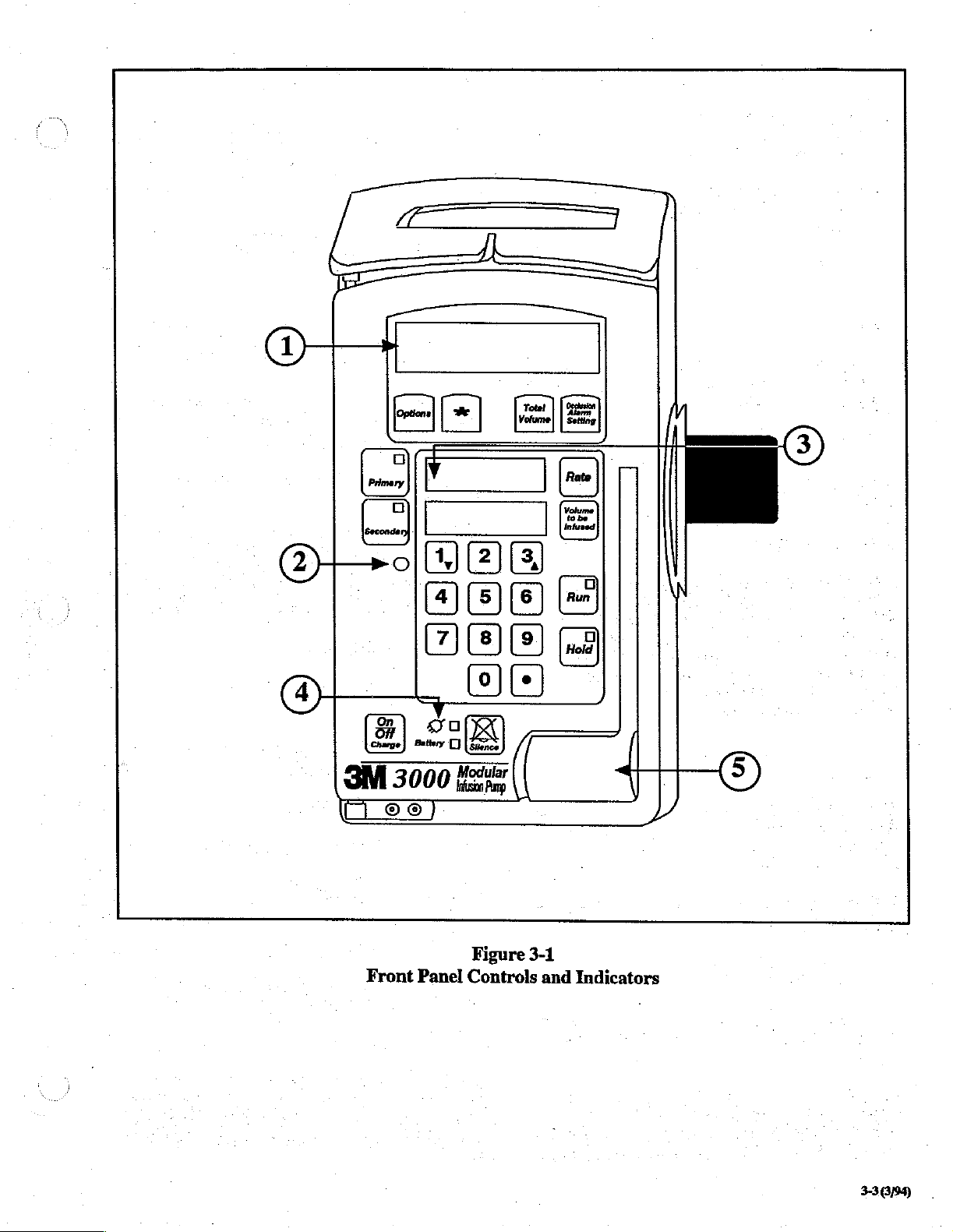
3.3
Front
(Reference
The
secondary
Then,
the
solution
alarm
are
additional
in
the
Controls
Panel
Figure
NOTE
Only
those
labeled
as
to
below.
1.
Message
The
Message
display,
infusion
consisting
status,
10
seconds
will
reappear
will
sound,
and
Micro
for
automatic
secondary
program
rather
pump
switches
according
occurs
following
message
Options
Controls
3-1.)
controls
and
function
Display
Display
of 2 lines
visual
of
entering
in
the
and
the
3100
sequential
medication
of
rate
than
entering
to
Primary
to a separate
delivery
and
section
of
And
And
Indicators
indicators
are
called
is
an
alphanumeric
by
alarms,
options,
the
new
rate,
display,
Message
have
the
non-insistent
Display
the
capability
delivery
is
delivered
and
volume
KVO
after
and
delivers
to
program.
of
the
primary
pumping
this
options
manual.
Indicators
not
specifically
out
using
numbers
liquid
16
characters.
and
other
the
will
flash
to
of
two
according
be
infused
secondary
the
The
ex-
crystal
It
shows
messages,
be
During
continuously
Display
(as
counts
up).
current
the
be
the
volt
operation,
will
fluid
is
down
Also,
status
data
in
stored
pump
lithium
shown
show
delivered,
as
status
the
in
nonvolatile
is
turned
battery
chip.
The
Running
change
Rate
while
sor
to
receive
using
the
display,
rate.
Press
3-2
(3/94)
rates
without
the
number
but
the
Run
Rate
the
in
volume
the
volume
lights
of
the
pump.
Message
on.
which
Change
interrupting
pump
new
rate
keys,
pump
to
lock
rate
and
the
Numeric
infused
the
Volume
in
will
be
When
Display
memory
The
memory
is
integrated
feature
is
operating
input.
the
new
will
continue
in
the
volume
to
be
infused
Displays.
for the
current
to
be
Infused
the
Message
appropriately
the
and
and
Display
lit
pump
is
Numeric
displayed
is
maintained
with
allows
you
fluid
delivery.
readies
After entering
rate
new
will
to
infuse
rate
setting.
the
the
appeat
will
be
The
Message
infusion
display
counts
to
show
the
turned
off,
Displays
again
the
to
will
when
by
a 3
memory
instantly
Pressing
microproces-
new
rate
in
the
at
the
original
If
Run
is
not
The
Message
and
when
for
approximately 1 minute.
The
backlight
when
the
AC
Power
With
the
backlight
with
the
approximately 1 minute.
the
Message
DC
Power
When
the
pump
pump
will
door
(Battery)
on
battery
Display
door
is
time
out
is
on
on
hold,
always
open,
the
Display
power,
is
opened.
feature
AC
be
backlight
approximately 1 minute
When
the
pump
is
running,
briefly,
The
then
general
rule
the
display
is
that
backlit
and
backlight
whether
reverts
informational
The
has
power
with
on.
With
After
timeout,
the
backlight
some
when
any key
backlight
different
and
battery
the
door
the
pump
will
time
will
tum
the
door
messages
to
the
messages
will
standard
is
pressed,
will
remain
characteristics
power:
closed,
if
the
on
out
door
the
hold,
after
is
and
on.
time
out
after
is
open
or
not.
are
displayed
message.
will
be
on
closed,
Page 13
ES
ЗМ
Gee)
Front
3000
3000
Mes
Panel
"odiar
ir
Figure
Controls
3-1
and
Indicators
330684
.
Page 14

displayed
which
for 5 seconds,
require
Pressing a key
it
will
cause
its
or
10
second
During
on
and
audio
The
various
9.
an
off
has
timeout
alarm
with
been
Message
input
will
which
has a different
screen
to
has
or
alert
the
audible
silenced.
Display
and
messages
be
displayed
be
instantly
expired
condition,
on
alarms
screens
with
for
10
display
displayed
the
first
the
backlight
and
remain
are
listed
instructions
or
seconds,
associated
before
with
the
message.
will
flash
on
after
the
in
Section
5
Occlusion
With
the
pump
Alarm
Setting
occlusion
desired
pressing
While
Setting
ever,
settings
setting
Run.
the
shows
the
setting
on hold.
pump
Alarm
on
hold,
advances
in
is
shown
is
the
setting
cannot
Setting
repeatedly
through
the
Message
in
the
running,
pressing
which
be
changed
Key
pressing
Low,
Display.
Message
Ocelusion
is
currently
until
Occlusion
Medium,
When
Display,
in
use.
the
pump
and
High
the
select
Alarm
How-
is
placed
it
by
Options
Pressing
functions.
Key
Options
To
instructions
Кеу
“The
(|
key
functions
Total
Press
(Primary,
delivered
displays
since
checked
‘pump
the
and
Volume
Total
Secondary,
since
total
the
display
when
on
hold,
Message
m.
Press
allows
select
in
the
Message
is
used
when
Key
Volume
it
was
hours
was
the
pump
the
total
Display
oh
*
to
you
to
scroll
and
set
up
desired
Display
in
the
programming
clearing Total
to
display
and
last
and
last
as
the
Rate
Taper)
cleared.
minutes
cleared.
is
running
volume
follows:
and
the
m
clear
through
option(s),
.
of
optional
Volume.
cumulative
which
Total
volume
pump
has
Total
volume
or
on
hold.
time
will
the
optional
follow
volume
has
been
also
been
may
With
be
shown
`
in
use
be
the
the
in
The
Occlusion
downline
the
pump
Low
means
teaches
and
The
when
The
rates.
viscous
100
High = 500
pump
tumed
Low
When
solutions,
“Occlusion
Occlusion
Primary
Selects
light
Ifa
the
primary
on
the
secondary
primary
Alarm
pressure
Setting
allowed
determines
in
the
alarms.
the
pump
will
alarm
mmHg
automatically
(2
mmHg
psi),
Medium = 250
(10
psi).
defaults
on.
setting
is
infusing
below
Alarm
Setting
designed
at
and/or
pump”
to
higher
with
alarm
if
not
Key & Indicator
delivery
key.
infusion
settings
as
shown
is
running,
momentarily.
the
administration
when
downline
mmHg
to
the
Medium
be
used
at
lower
flow
rates,
with
small
diameter
may
activate.
appropriate
by
the
for
green
press Primary
amount
set
of
before
pressure
(5
psi),
setting
infusion
more
catheters,
Change
infusion.
indicator
to
view
the
the
To
clear
total
is
not
pressed,
Occlusion
to
the
standard
With
the
pump
displayed
“The
standard
as
total
message
message.
Volume.
In
either
case,
volume
the
exceeds
pump
was
is
99
3-4(3/94)
volume,
Alarm
message.
running,
follows:
m.
infusions
remains
the
last
cleared.
tumed
hours,
press
pressing
Setting)
oh.
The
time
59
will
the
om
for 5 seconds
pump
displayed
It
on,
whether
minutes,
Total
Volume,
any
other
return
total
volume
must
is
includes
on
hold
the
display
key
the
before
be
on
the
time
all
time
or
then
press
(except
Options
Message
and
time
reverting
hold
to
clear
since
during
running.
shows
[X).
If
or
Display
will be
to
the
Total
total
which
If
time
100+hrs.
Secondary
Selects
Press
the
2.
The
adjusts
Located
secondary
Secondary
secondary
Photo
photo
the
3.
Pumping
on
indicator,
downward
the
rate.
consisting
pumping
Sensor
sensor
intensity
the
fashion
Key & Indicator
delivery
while
rate
momentarily.
constantly
of
the
the
as
shown
primary
measures
LED
displays
Indicator
left
side
of
the
Rate
of
three
horizontal
to
indicate
‘indicator
is
fluid
approximately
by
the
yellow
line
is
running
room
light
accordingly.
Display,
delivery.
the
lines,
The
moves
proportional
light.
to
view
and
pumping
in
a
speed
of
to
the
Page 15
Rate
Key & Numeric
The
Rate
Numeric
which
the
current
With
the
pump
display and
-is
entered
approximately
readies
the
display.
Display
infusion
on hold,
the
pump
will
10
seconds.
Display
shows
is
being
pressing
Rate
for
rate
default
the
rate,
in
delivered.
blanks
entry.
to
the
old
rate
mL/h,
the
If
no
at
rate
new
after
rate
On/Off
On/Off
the
routine.
Another
that
the
door
is a software
central
On/Off
switch
opening
pump
is
closed.
Key
controlled
microprocessor’s
is
deactivated
is
wired
electrically
the
door
when
on.
The
pump
cannot
switch.
power
while
the
pump
be
Pressing
up
and
the
pump
parallel
is
off
tumed
off
power
is
with
will
also turn
unless
it
activates
down
running.
On/Off
so
the
Volume
The
volume,
counts
running.
With
blanks
infused
restore
Number
The
Infused,
The 1 and 3 keys
indicators
«
(decimal)
Press
ml/h.
to
Volume
in
down
the
pump
the
display
entry.
the
number
and
for
the
decimal
be
to
be
mL,
which
from
on hold,
Pressing
previously
Keys
keys
when
use
Key
Infused
Infused
remains
the
initial
pressing
and
readies
Volume
set
Volume
(0-9)
are
used
working
are
also
marked
during
Quick
key
to
enter
Key & Numeric
Numeric
setting
to
in
Display
to
be
when
Volume
the
pump
to
be
to
set
Rate,
certain
with
Rate
rates
and
shows
delivered.
the
Te
for
volume
Infused
be
Infused.
Volume
Options.
up
and
Change.
volumes
Display
the
The
display
pump
is
Be
Infused
to
twice
will
To
Be
down
in
10ths
be
DANGER
Potentially
the
pump
plugged
These
transformer
board,
nects.
ning
dangerous
housing
in,
regardless
voltages
and
and
the
Always
disassembly.
CAUTION
Turning
circuits,
transformer.
charging
is
Silence
Press
used
pump
the
before
the
but
circuit
plugged
Key
Silence
when
on
hold
pump
must
plugging
pump
does
in,
it
is
voltages
is
opened
of
are
present
AC
fuse
RFI
filter
unplug
The
regardless
to
undesirable
(e.g.,
remain
the
off
removes
not
remove
transformer
are
energized
silence
it
the
when a low
on
in).
are
and
the
on
or
in
the
on
the
CPU/power
where
the
AC
power
power
AC
and
whenever
of
on/off
audio
alarm.
or
unnecessary
battery
battery
operation
exposed
the
power
off
state
following
power
cord
before
from
power
from
12
volt
the
state.
Silence
to
alarm
for a short
whenever:
cord
is
of
the
pump.
areas:
the
supply
cord
con-
begin-
most
the
battery
power
cord
can
be
place
the
occurs
and
time
Run
Key & Indicator
Press
Run
to
will be
programmed
rate.
If
not
Run
Hold
lit
steadily
the
door
is
in
place,
or
is
also
used
Change.
Key & Indicator
Pressing
on
pump
When
will
Hold
hold,
temporarily
is
on hold,
the
flash
until
pump
begin
when
rate,
and
not
closed,
pump
to
stops
the
is
either
infusing.
fluid
flashes
the
set
up
set a new
the
infusion
silences
red
indicator
alarming,
Hold,
Silence,
The
green
indicator
is
being
delivered
when
delivering
administration
is
incomplete,
rate
during
or,
an
audio
on
the
indicator
if
the
alarm.
the
or
Run
set
Run
Running
pump
key
light
is
on
at
the
at
the
safety
is
disabled,
Rate
is
already
When
will
be
on
the
pressed.
the
KVO
clip
the
lit.
key
key
is
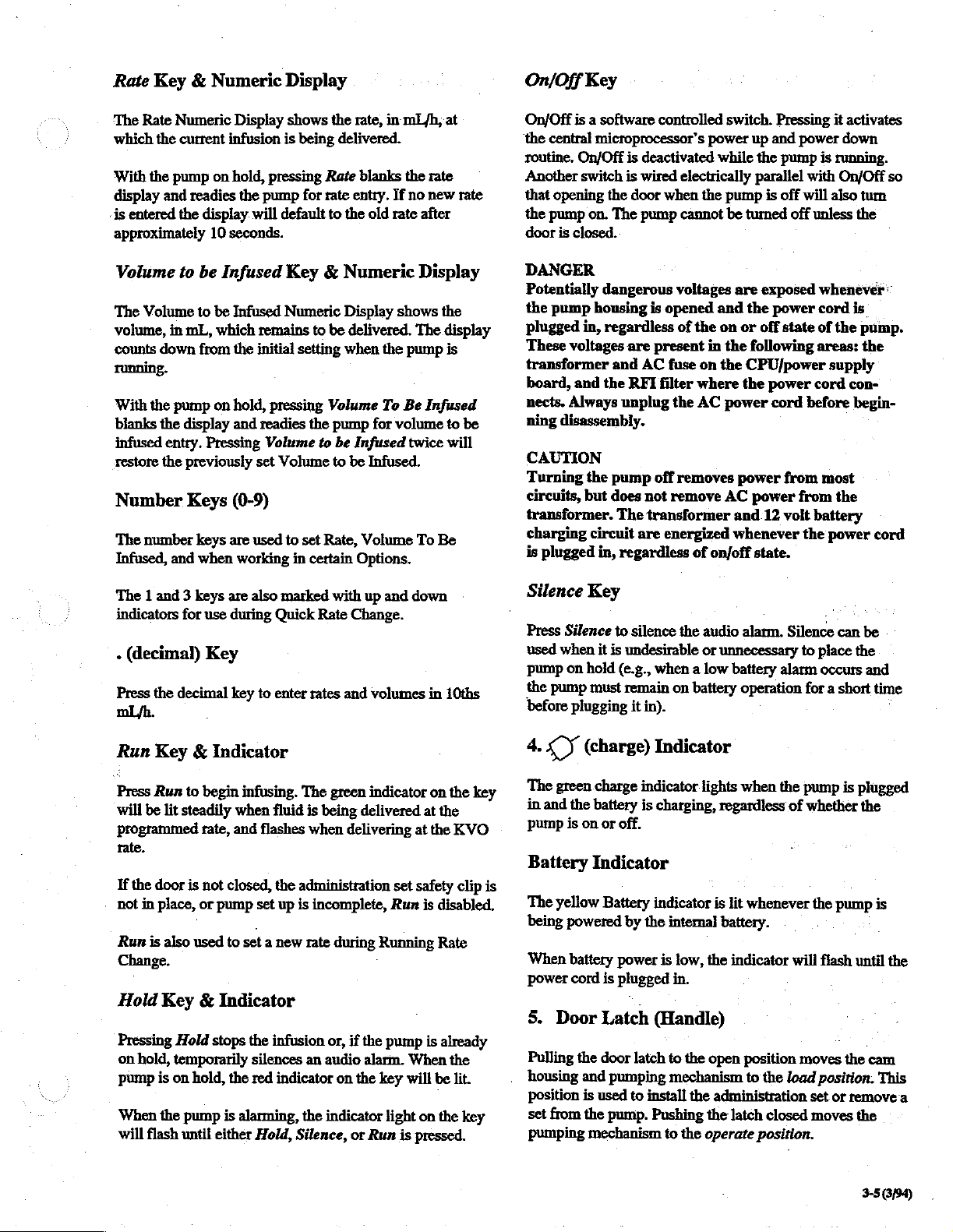
4.
sy
The
green
in
and
the
pump
is
Battery
The
yellow
being
powered
When
battery
power
cord
5.
Door
Pulling
housing
position
set
from
pumping
(charge)
charge
indicator
battery
on
Indicator
the
and
is
the
mechanism
is
or
off.
Battery
by
power
is
plugged
Latch
door
latch
pumping
used
to
pump.
the
install
Indicator
lights
charging,
indicator
internal
is
(Handle)
to
mechanism
Pushing
to
regardless
is
lit
battery.
low,
the
indicator
in.
the
open
the
administration
the
latch
the
operate
when
the
of
whenever
will
position
to
the
load
closed
position.
pump
is
whether
the
pump
flash
moves
position.
set
or
moves
plugged
the
is
until
the
cam
This
remove
the
3-5
6/54)
the
a
Page 16
If
the
pump
is
running
and
the
door
is
opened,
the
4.
Ground
Stud
Door
alarm
is
activated.
alarm.
Once a set
placed
safety
is
pulled
preventing
in
the
clip
open,
is
to
CAUTION
To
prevent
upper
clamp
door.
Inside
Pump
(Reference
1.
Cassette
Place
four
holes
pins
and
press
open
Pressing
loaded
retention
allow
for
the
safety
gravity
pump
on
the
Door
Figure
flow
and/or
3-2.)
Loading
on
cassette
cassette
Silence
into
the
slot,
closing
fluid
delivery.
clip
through
cassette
administration
pump
is
allowed
the
or
and
the
damage,
Pins
(flat
side
into
place.
Hold
the
door
When
set.
set
out)
will
safety
opens
the
to
close,
open
before
over
silence
clip
is
the
door
latch
thus
the
closing
four
loading
the
the
The
ground
current
5.
Pole
Turn
the
an
IV
6.
Modular
The
modular
pumps
7.
Modular
Press
to
stud
and
ground
Clamp
pole
clamp
pole.
connection
together
disconnect
is
used
as a test
line
resistance
clockwise
Connection
allows
for
multiple
Disconnect
pumps
from
point
levels.
firmly.to
you
to
infusion
lines.
Button
each
other.
to
measure
secure
connect
leakage
the
pump
up
to
to
3
2.
Safety
Place
administration
completely
Clip.is
correctly
Back
Panel
(Reference
1.
Alarm
Turn
to
alarm
cannot
2.
Computer
This
is
an
3.
Keypad
Pressing
Lockout
display
‘
entries
are
will
timeout
Clip
forward.
loaded.
Controls
Figure
Volume
increase
RS
be
232
or
completely
Leckout
the
button
feature.
will
read
allowed.
and
Retention
set
Safety
Pump
will
3-3.)
Control
decrease
audio
silenced.
Port
Port
for
computer
Button
activates
When
Keypad
After 5 seconds,
revert
(or
the
button
lockout,
to
standard
Slot
Clip
in
slot
and
not
operate
alarm
deactivates)
is
message.
unless
volume.
connection.
the
pressed,
the
the
and
no
Message
push
Safety
Audio
Keypad
message
keypad
Display
Pressing
and
restores
message
3-6
(3/94)
the
button
all
keypad
display
again
when
deactivates
functions.
the
lockout
the
There
is
feature
lockout
feature
no
change
is
deactivated.
to
the
Page 17
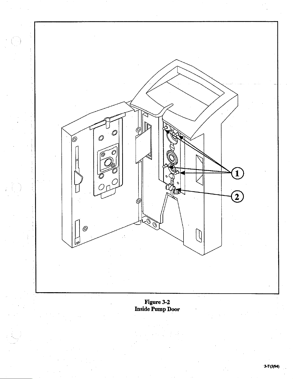
Figure
Inside
Pump
3-2
Door
37889
Page 18
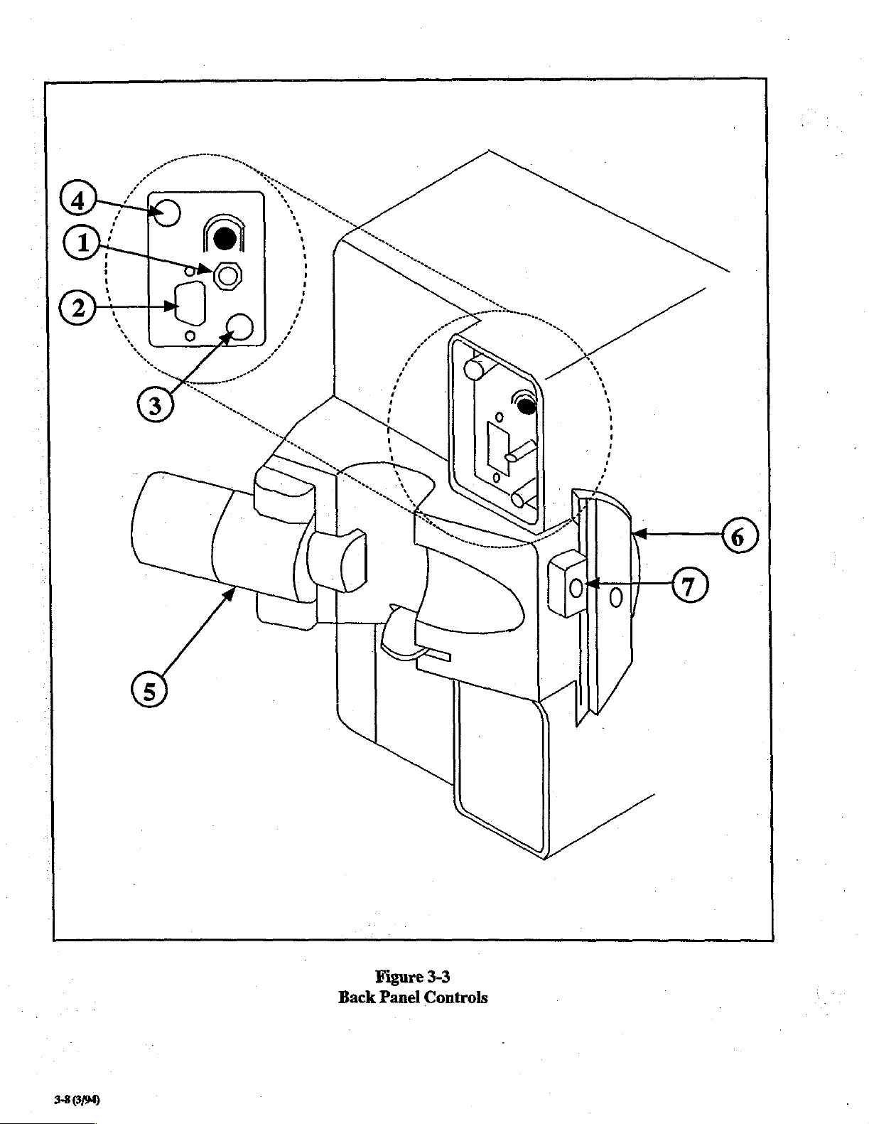
Figure
Back
3-8
(3/94)
Panel
3-3
Controls
Page 19
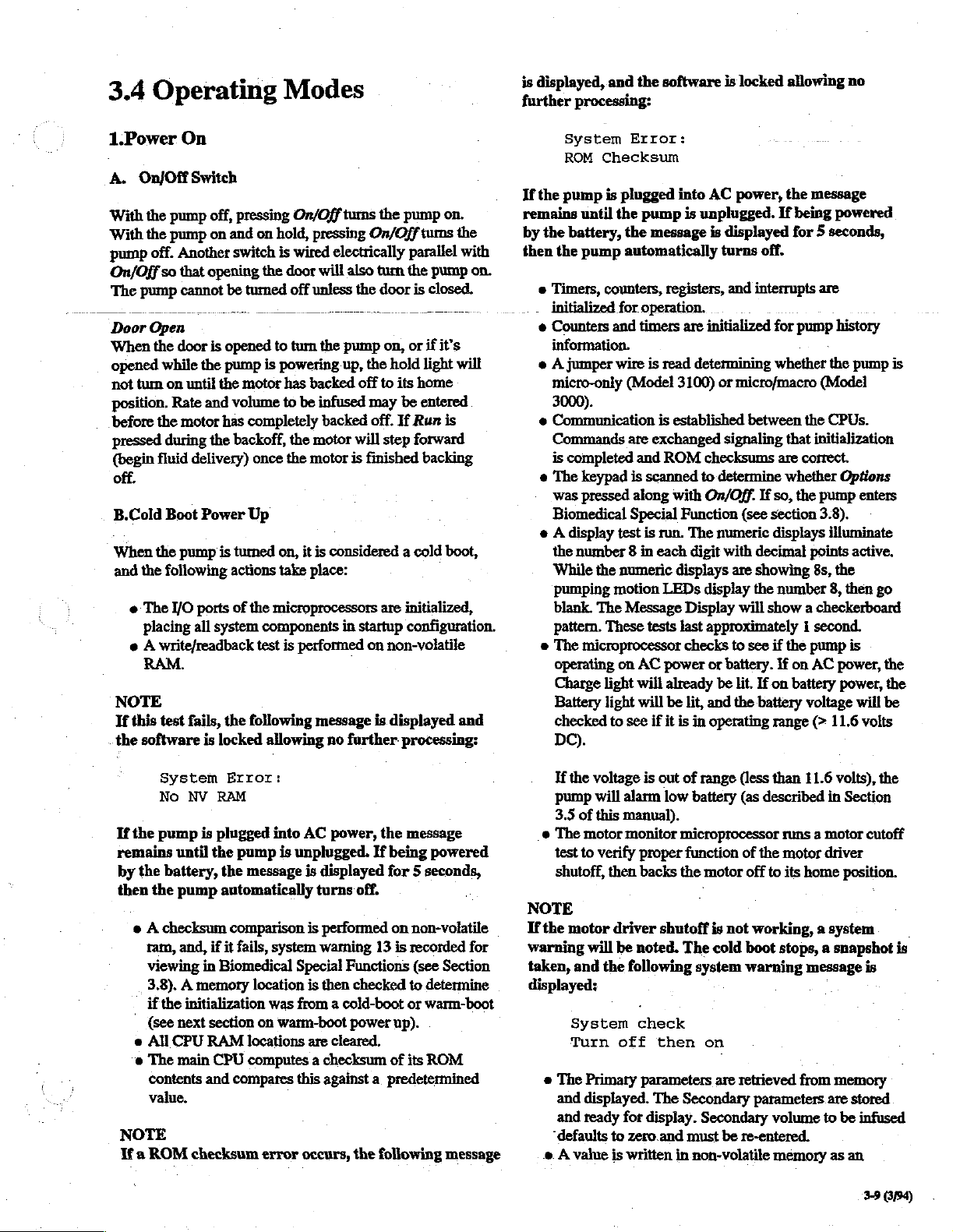
3.4
Operating
Modes
is
displayed,
further
processing:
and
the
software
is
locked
allowing
no
1.Power
A.
With
With
pump
On/Off
The
Door
When
opened
not
position.
before
pressed
(begin
On/Off
the
pump
the
pump
off.
so
that
pump
Open
the
door
while
turn
on
Rate
the
during
fluid
On
Switch
Another
cannot
until
motor
delivery)
off.
B.Cold
When
and
Boot
the
pump
the
following
è
The
I/O
ports
placing
e A writefreadback
all
RAM.
NOTE
Tf
this
test
fails,
the
software
off,
pressing
on
and
switch
opening
be
is
opened
the
pump
the
motor
and
volume
has
the
backoff,
Power
is
turned
actions
of
system
the
is
locked
On/Off
on
hold,
pressing
is
wired
the
door
will also
turned
off
unless
to
turn
the
is
powering
has
backed
to
be
infused
completely
once
the
the
backed
motor
motor
Up
on,
it
is
considered a cold
take
place:
the
microprocessors
components
test
is
performed
following
allowing
message
no
turns
the
pump
On/Off
electrically
turn
the
pump
up, the
off
may
off.
will
is
finished
in
startup
on
further:
turns
parallel
the
door
is
on,
or
if
hold
to
its
home
be
entered
If
Run
step
forward
are
initialized,
configuration.
non-volatile
is
displayed
processing:
on.
the
with
pump
closed.
it’s
light
will
is
backing
boot,
and
on.
System
ROM
If
the
pump
remains
by
the
battery,
then
the
e
Timers,
initialized
e
Counters
information.
e A jumper
micro-only
3000).
è
Communication
Commands
is
completed
®
The
was
Biomedical
e A display
the
While
pumping
blank.
pattern.
e
The
operating
Charge
Battery
checked
DC).
Error:
Checksum
is
plugged
until
the
pump
the
message
pump
automatically
counters,
for
and
wire
registers,
operation.
timers
is
read
(Model
is
established
are
exchanged
and
ROM
keypad
pressed
is
scanned
along
with
Special
test
is
run.
number 8 in
the
The
These
each
numeric
motion
Message
tests
LEDs
microprocessor
on
AC
power
light
will
already
light
will
be
to
see
if
it
into
AC
is
unplugged.
is
displayed
turns
and
are
initialized
determining
3100)
or
power,
microfmacro
the
If
being
for 5 seconds,
off.
interrupts
for
pump
whether
between
signaling
checksums
to
determine
On/Off.
Function
The
numeric
digit
with
displays
are
display
Display
last
checks
lit,
is
wili
approximately 1 second.
to
or
battery.
be
lit.
and
the
in
operating
that
are
whether
If
so,
the
(see
section
displays
decimal
showing
the
number
show a checkerboard
see
if
the
If
on
If
on
battery
battery
range
message
powered
are
history
the
pump
is
(Model
the
CPUs.
initialization
correct.
Options
pump
enters
3.8).
illuminate
points
active.
8s,
the
8,
then
go
pump
is
AC
power,
voltage
(>
11.6
power,
will
volts
the
the
be
System
No
If
the
pump
remains
by
the
battery,
then
the
+ À checksum
ram,
viewing
3.8). A memory
if
the
{see
è
All
e
The
contents
value.
NOTE
Ifa
ROM
Error:
NV
RAM
is
plugged
until the
pump
pump
the
message
automatically
comparison
and,
if
it
fails,
in
Biomedical
location
initialization
next section
CPU
RAM
main
and
checksum
on
locations
CPU
computes a checksum
compares
error
into
AC
power,
is
unplugged.
is
displayed
turns
is
performed
system
was
warning
Special
is
then
Functions
from a cold-boot
warm-boot
this
occurs,
power
are
cleared.
against a predetermined
the
message
If
being
for 5 seconds,
off.
on
non-volatile
13
is
recorded
(see
checked
to
or
up).
of
its
the
following
powered.
for
Section
determine
warm-boot
ROM
message
If
the
pump
3.5
of
e
The
test
to
shutoff,
NOTE
If
the
motor
warning
taken,
and
displayed:
System
Turn
e
The
and
and
“defaults
© A value
voltage
will
motor
alarm
this
manual).
monitor
verify
then
is
proper
backs
driver shutoff
will
be
noted.
the
following
check
off
Primary
displayed.
ready
parameters
The
for
display.
to
zero.and
is
written
out
of
range
(less
low
battery
microprocessor
function
the
motor
is
not
The
cold
system
then
on
are
retrieved
Secondary
Secondary
must
be
in
non-volatile
than
11.6
volts),
(as
described
in
Section
runs a motor
of
the
motor
driver
off
to
its
home
position.
working, a system.
boot
stops, a snapshot
warning
parameters.are
message
from
volume
memory
stored
to
be
re-entered.
memory
as
an
the
cutoff
=
is
is
infused
3.9
(3/94)
Page 20
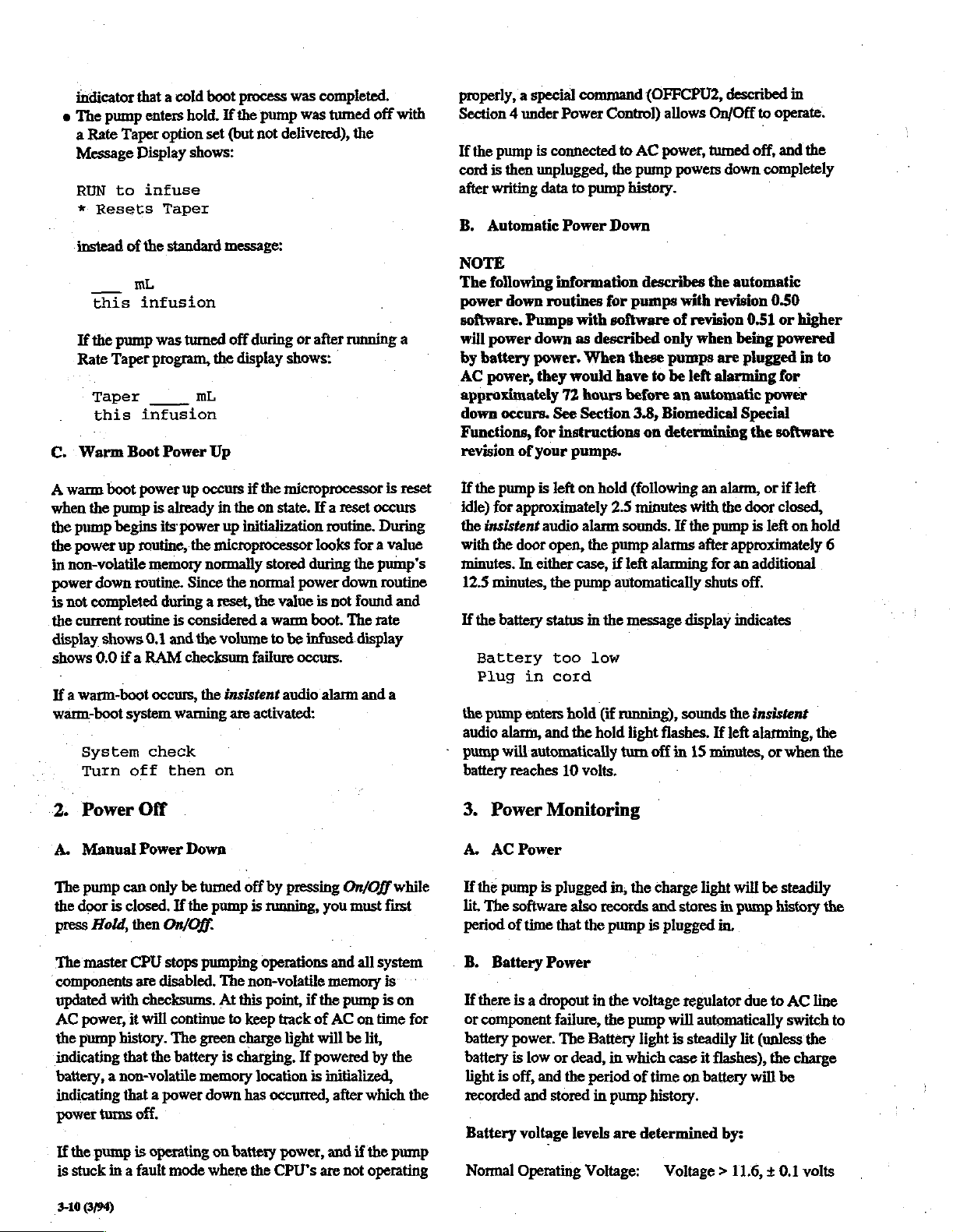
indicator
©
The
a
Rate
Message
RUN
*
instead
If
Rate
C.
Warm
A
warm
when
the
the
pump
the
power
in
non-volatile
power
is
not
the
current
display
shows
that a cold
pump
Taper
Display
to
Resets
of
mL
this
the
infusion
pump
Taper
Taper
this
Boot
boot
power
pump
begins
up routine,
down
routine.
completed
routine
shows
0.0
if a RAM
If a warm-boot
warm-boot
System
Turn
system
off
boot
enters
hold.
option
set
shows:
infuse
Taper
the
standard
was
turned
program,
infusion
Power
is
its
memory
the
mL
Up
up
occurs
already
in
power
the
microprocessor
normally
Since
during a reset,
is
considered a warm
0.1
and
the
volume
checksum
occurs,
the
waming
check
then
on
process
If
the
(but
was
pump
was
not
delivered),
message:
off
during
or
display
the
up
shows:
if
the
microprocessor
on
state.
initialization
stored
the
normal
insistent
are
power
the
value
to
be
infased
failure
occurs.
audio
activated:
completed.
tumed
the
after
running
If a reset
routine.
looks
for a value
during
the
down
is
not
found
boot.
The
display
alarm
and
off
with
a
is
reset
occurs
During
pump's
routine
and
rate
a
properly, a special
Section 4 under
If
the
pump
is
connected
cord
is
then
unplugged,
after
writing
B.
Automatic
data
NOTE
The
following
power
down
routines
software.
will
by
AC
approximately
down
Functions,
revision
If
the
idle)
the
with
minutes.
12.5
If
the
Battery
Plug
the
audio
-
pump
battery
Pumps
power
battery
power,
down
power.
they
occurs.
for
of
your
pump
is
for
approximately
insistent
the
audio
door
In
either
minutes,
battery
in
pump
enters
alarm,
will
automatically
reaches
See
left
open,
the
status
too
cord
and
command
Power
Control)
to
AC
the
pump
to
pump
history.
Power
Down
information
for
pumps
with
software
as
described
When
these
would
72
have
hours
Section
before
3.8,
instructions
pumps.
on
hold
(following
2.5
minutes
alarm
sounds.
the
pump
case,
if
left
pump
automatically
in
the
message
low
hold
(if
running),
the
hold
light
turn
10
volts.
(OFFCPU2,
allows
power,
powers
describes
with
of
revision
only
when
pumps
to
be
left
an
automatic
Biomedical
on
determining
an
with
If
the
alarms
after
alarming
shuts
display
sounds
flashes.
off
in
15
described
On/Off
to
operate.
tumed
off,
and
down
completely
the
automatic
revision
are
alarming
0.50
0.51
being
powered
plugged
or
for
power
Special
the
software
alarm,
or
if
the
door
closed,
pump
is
left
approximately
for
an
additional
off.
indicates
the
insistent
If
left
alarming,
minutes,
or
in
the
higher
in to
left
on
hold
when
6
the
the
2.
Power
A.
Manual
The
pump
the
door
press
Hold,
The
master
components
updated
AC
power,
the
pump
indicating
battery, a non-volatile
indicating
power
If
the
is
stuck
310
694)
Off
Power
can
is
closed.
then
CPU
are
with
it
history.
that
that a power
turns
off,
pump
is
in a fault
Down
only
be
If
the
On/Off.
stops
disabled.
checksums.
will
continue
The
the
battery
operating
mode
turned
off
pump
is
pumping
The
non-volatile
At
this
to
keep
green
charge
is
charging.
memory
down
has
on battery
where
the
by
pressing
running,
you
operations
point,
if
the
track
of
light
will
If
powered
location
is
occurred,
power,
CPU's
are
On/Off
and
memory
pump
AC
be
initialized,
after
and
not
while
must
first
all
system
is
is
on
time
lit,
by
the
which
if
the
pump
operating
on
for
the
3.
Power
A.
AC
If
the
pump
lit.
The
period
of
B.
Battery
If
there
or
component
battery
battery
light
is
recorded
Battery
Normal
Monitoring
Power
is
plugged
software
is a dropout
power.
is
off,
voltage
Operating
also
time
that
the
Power
failure,
The
low
or
dead,
and
the
and stored
levels
Voltage:
in,
the
records
pump
in
the
voltage
the
pump
Battery
in
which
period
of
in
pump
are
charge
light
will
and
stores
in
pump
is
plugged
will
light
case
time
in,
regulator
automatically
is
steadily
on
lit
it
flashes),
battery
due
history.
determined
by:
Voltage > 11.6, + 0.1
be
steadily
history
to
AC
switch
(unless
the
will be
the
line
to
the
charge
volts
Page 21

Low
Battery:
11.0 < Voltage
>/=
11.6, + 0.1
volts
(6
minutes
if
door
is
open)
“On
Hold”
alarm.
Dead
Battery:
Automatic
Once a low
or
automatic
pump
is
plugged
with
another
See
Alarms
battery.
4.
Run
After
setting
fluid
delivery.
volume
cassette
closed
battery
pressed
will
the
When
be
motor
the
e
the
e
the
to
must
or
Run
voltage
while
solidly
green
volume
volume
e
Primary
Secondary
or
neither
@
the
Pumping
action
e
the
Message
this
or
Taper
this
o
the
Volume
disabled
e
if
Quick
active
e
if
Rate
keys
a
if
Options
active
corresponding
’
seconds,
message.
10.0 < Voltage
Tum
Off:
battery
state
turn
off)
in,
state,
or
in
Section
infusion
All
necessary
be
infused),
be
properly
is
disabied.
must
the
motor
lit
and
finishes
pump
is
run
to
backing
running
light
be
is.infused
is
lit
if
light
is
lit
Motion
Display
mL
infusion
infusion
to
Rate
Change
for
changing
is
pressed
are
active
is
pressed,
so
that
an
the
Message
>/=11.0, + 0.1
Voltage < 10.0, + 0.1
occurs
(low
battery,
it
will
remain
the
voltage
the
pump
3.5 for
parameters,
the
Safety
loaded, and
If
be
greater
is
backing
the
pump
in
that
drops
to a level
is
turned
descriptions
Run
is
data
must
be
Clip
must
the
operating
than
off,
will
on
11.0
the
not
start
off.
forward:
is
steadily
infused
pump
is
is
lit
if
if
running a Rate
Display
shows
mL
be
Infused
the
(Running
the
option
number.
lit
counts
down
running a primary
running a secondary
Taper
is lit
to
the
volume
or
or
and
is
active,
KVO
On/Off
the
rate
Rate
Change),
number
may
If
Display
no
be
key
keys
selected
is
reverts
volts
dead
state
unless
consistent
off,
then
of
low
pressed
entered
be
in
door
must
battery,
volts.
If
green
running
in
the
infusion,
infusion
convey
infused:-
this
şt
m.
this
infusion
keys
1(4)
and
the
and
[x]
by
pressed
to
standard
volts
battery,
the
on.
and
dead
to
begin
(rate
and
place,
the
be
the
Run
is
run
light
until
display
as
infusion,
pumping
:
mL
infusion
are
3(4)
are
number
will
be
its
within
10
During
silences
if
door
to
alarm
5.
If
stops
Message
During
and
cycle.
Message
audio
An
or
If
minutes
the
says:
The
door
ーーー
when-the
6.
Upon
pump
by
show
To
in
secondary
Display
is
seconds,
7.
When
secondary
are
to
an
insistent
the
alarm
open).
restart
the
will
reoccur.
Hold
Hold
is
pressed
fluid
delivery,
Display
an
insistent
the
red
hold
The
appropriate
Display.
alarm.
insistent
Silence.
the
pump
if
door
backlight
On
Hold
On
Hold
open)
will
keypad-is
Primary
pump
was
turned
the
green
the
primary
verify
secondary
primary,
running,
displayed
be
press
rate
shows
the
then
Secondary
the
pump
light
infused)
alarm,
for
Pressing
pump.
If
while
the
shows
alarm,
light
flashes
The
alarm
may
is
left
on
is
open),
and
hold
timer
(2.5
be
reset
locked.)--—
power
up,
off
primary
operating
Secondary.
and
volume
the
secondary
secondary
they
revert
is
operating
is
steadily
both
in
and
the
pressing
Hold
approximately
Run
silences
the
problem
the
red
the
hold
is
pump
is
hold
light
standard
is
automatically
at a rate
alarm
message
backlight
be
hold
the
light
minutes
when
the
in
Rate
light.
flashes
silenced
for
more
insistent
flash,
and
if
door
any
keys
pump
enters
Taper).
When
Primary
by
patameters.
infusion
parameters
The
displays
to
be
infused,
volume
parameters
back
to
Primary.
in
Secondary,
lit,
and
the
the
numeric
Message
display
Display.
or
Silence
2.5
minutes
the
alarm
not
corrected
running,
is
steadily
(6
and
the
lit,
message.
entered,
of 1 Hz
appears
than
audio
the
at
in
along
with
pressing
2.5
minutes
alarm
either
Message
50%
closed, 6 minutes
are
pressed
Primary
Primary
is
is
lit,
while
(unless
indicated
the
the
show
and
the
infused.
are
secondary
If
displayed
the
yellow
(rate
and
minutes
attempts
the
pump
and
the
duty
the
the
Hold
(6
sounds,
Display
if
(except
the
displays
pump
is
the
Message
the
pump
for
5
parameters
volume
During a non-insistent
silences
Hold
the
alarm
silences
the
alarm,
without
alarm
until
pressing
stopping
fluid
the
approximately
Run
or
Silence
delivery;
pressing
2.5
minute
After a secondary
two
repetition
automatically
of
the
to
Primary.
infusion
is
complete,
zon-insistent
the
alarm,
pump
then
sounds
switches
3-11
(3/94)
~
Page 22

To
verify
the
primary
is
in
secondary,
primary
Display
running,
before
rate
and
shows
the
primary
reverting
If a secondary
start
the
pump
displayed
The
alarm,
secondary
secondary
Held,
infused
recall
Secondary
operation.
for 5 seconds:
Secondary
was
set
pump
sounds
begins
volume
is
desired
then
Secondary,
parameters
previous
delivery
© '
infusion
press
Primary.
volume
the
primary
parameters
to
secondary.
infusion
in
Primary,
two
repetitions
infusing
to
the
be
after
(or
press
setting),
is
not
parameters
The
to
be
infused,
volume
has
been
the
following
primary
infused
re-enter
the
then
is
message
the
Volume
press
available
while
displays
and
infused.
are
displayed
set
up,
and
message
of
the
non-insistent
parameters,
cleared.
If
is
displayed,
secondary
to
be
Infused
Run.
during
Rate
the
pump
show
the
the
Message
If
the
pump
for 5 seconds
you
attempt
is
and
the
running
press
volume
twice
Taper
in
to
is
to
be
to
When
the
audio
alarm
flashing
message
When a non-urgent
(infusion
insistent
light
battery,
50%
alarm
silences
If
insistent
The
and
the
displayed.
complete)
audio
flashes
duty
more
at
the
yellow
cycle.
without
the
audio
than
one
stopping
alarms
insistent
Repetitions
audio
of
Message
alarm
about 1 Hz
Pressing
alarm
alarm
take
high high
seconds
Frequency
Frequency
The
non-insistent
of
low
of
high
is
silenced,
Display
alert
condition
and
initial
is
activated.
with
battery
light
Run
fluid
and
condition
precedence
alarm
specification
is
approximately
is
approximately
audio
alarm
the
remains
low
In
50%
flashes
or
Silence
delivery.
stops
exists
over
low
chime
specification
hold
light
lit
with
occurs,
battery,
KVO,
duty
at
such
the
the
cycle.
about 1 Hz
silences
Pressing
fluid
delivery.
simultaneously,
non-insistent
is:
repeated
2200
Hertz
2900
Hertz
is:
stops
the
as
KVO
non-
green
In
low
the
Hold
every
alarm
run
with
audio
alarms.
2.25
3.5
The
buzzers,
sense
buzzer
The
Alarms
audio
patt
of
one
of
which
that
the
other
fails,
the
“microphone”
Model
alarm
Continuous
low
chime)
pump
be
silenced
tent
alarm
during
During
until
audio
the
audio
the
same
pauses;
failure
Back
patient
Therapy-trained
3000 & Micro
pattems;
audio
signals
will
continue
by
pattern
which
an
insistent
the
cause
alarm
is a special
alarm
tone
it
occurs
has
occurred.
Up
or
Continuous
use
and
non-insistent,
pressing
the
of
system
as
have
technician.
the
alarm
system
normally
is
functioning
acts
buzzer
3100
use
insistent,
alarm.
The
non-insistent
an
alert
condition
to
operate.
Run,
The
Silence,
(high/high/low
pump
will
stop
alarm
condition,
the
alarm
is
corrected.
high
pitched
fails.
The
the
Back
Up
audio
to
indicate
an
electromechanical
Should a pump
tones,
remove
it
repaired
by a qualified,
consists
of
as a microphone
properly.
If
sounds
four
types
Back
pattem
during
which
non-insistent
or
Hold.
chime)
running
signals a condition
and
the
pump
The
Back
alarm,
and
Continuous
alarm,
but
alarm
with
the
pump
two
piezo
the
audio
the
audio
of
audio
Up,
and
alarm
The
enter
will
occurs
alarm
with
system
either
from
3M
Infusion
to
a
(high/
the
can
insis-
hold.
not
run
Up
if
uses
no
the
Repetitions
seconds
Frequency
Frequency
The
Back
Repetitions
second
Frequency
The
Continuous
Same
high
NOTE
The
Back
high
pitched
primary
not
patient
audio
working
use
occur.
of
high
of
low
is
of
high
is
Up
audio
alarm
of
high
is
approximately
audio
pitched
Up
and
Continuous
patterns,
or
the
properly.
immediately
low
chime
repeated
approximately
approximately
specification
pitched
tone
repeated
3000
alarm
specification
tone
as
Back
Up
audio
and
are a clear
pump
electromechanical
The
pump
should
either
every
2200
2900
is:
Hertz
alarm,
alarms
indication
must
be
of
2.25
Hertz
Hertz
every
is:
without
are
removed
these
alarms
1.5
pause
shrill,
that
system
from
is
Except
red
where
hold
Display
message
3-42
(3/94)
noted,
light
illuminates
flashes
with
is
displayed.
when
the
an
alarm
and
flashes
alarm
and
condition
at 1 Hz.
an error
or
occurs,
The
alarm
-
the
Message
+
Page 23

3.6
Alert/Alarm
Alerts:
1.
KVO
this
In
Primary
complete,
(Keep
sounds,
slows
Display
KVO
this
(
infused
The
pump
KVO
rate
‘Silence
running
If
Hold
silenced.
Message
this
(
infused
infusion
and
the
pump
Vein
Open)
the
green
its
flashing
flashes
infusion
indicates
was
programmed).
continues
(3.0
mL/h,
or
Run
at
the
KVO
is
pressed, the
The
set
Display
mL
infusion
shows
was
programmed).
mL
Rate
Taper
automatically
rate.
In
run
light
to
the
minimum
and
shows:
mL
the
volume
running
unless
to
silence
rate
the
for
pump
rate
reappears
switches
the
volume
Descriptions
modes,
KVO,
flashes,
to
when
the
infusion
the
infused
and
the
set
audio
switches
the
rate,
the
rate
alarm
to
the
KVO
non-insistent
Pumping
and
since
rate
is
Indicator
the
Message
volume
display
shows
lower). Press
and
continue
approximately 6 minutes.
stops
and the
in
the
standard
infused
audio
rate
display,
message:
since
volume
alarm
is
alarm
to
be
is
and
the
to
be
the
|
cancels
3.
The
Running
pleted
alarm
the
Rate
not
rate
change
Rate
or
completed
sounds,
low
battery
change
completed
Change
the
following:
Rate
not
The
Silence
delivery,
completed
pump
to
and
change
continues
silence
correctly
procedure.
4.
Secondary
was
The
set
up,
When
audio
set
secondary
but
Run
Run
is
pressed,
alarm
sound,
alert
shows:
Secondary
was
set
After 5 seconds,
message,
delivery
secondary
and
primary
is
desired,
infusion.
condition.
not
completed
is
improperly.
Message
to
run
the
audio
perform
is
activated
is
pressed
two
and
the
the
Message
delivery
press
Press
alert
is
attempted,
but
The
Display
at
alarm
the
original
without
the
Running
SECONDARY
WiLL
WHEN
flashes
if a secondary
while
the
pump
repetitions
Message
Display
is
continued.
Hold,
press
Run
while
triggered
either
non-insistent
THIS
whet
not
and
shows
rate.
Press
stopping
Rate
Go
Te
OCC
com,
audio
fluid
Change
VTB/
ZELO
infusion
is
in
Primary.
of
the
non-insistent
Display
Secondary,
pump
flashes
switches
to
If
secondary
is
in
standard
and
Secondary.
the
Run
VRS
is
and
reset
or
2.
Low
Plug
The
Low
Battery
falls
between
flashes,
following
This
The
pressing
by
also
but
period
that
Plugging
the
Low
Plug
alert
audio
Silence
pressing
returns
the
battery
elapses
time).
the
battery
in
cord
alert
11.0
and
non-insistent
appears
battery
condition
alarm
in
Hold
the
Message
light
again
pump
in
the
cord
does
can
be
or
Run
to
stop
continues
(unless
in
yet
Ap2
isfriggered
11.6
audio
Message
not
silenced
without
fluid
Display
turns
when
volts
DC.
alarm
Display:
stop
fluid
for
stopping
delivery.
to
flashing
the
pump
off
the
sef
the
The
battery
sounds,
delivery.
up
to 6 minutes
fluid
Silencing
its
standard
until
is
plugged
flashing
battery
battery
voltage
light
and
the
by
delivery,
the
alarm
message,
the 6 minute
in
during
light
or
and
Alarms:
5.
Pump
needs
service
The
Models
conditions
check
shut
down
audio
the
pump.
When a system
technician
The
error
alarms
Pump
service
3000 & Micro
to
detect
each
other
the
alarm
should a malfunction
for
message
is:
needs
system
and
many
pump
with
error
occurs,
further
inspection.
in
the
3100
monitor
errors.
of
the
the
Continuous
the
pump
Message
The
two
system
be
detected.
must
Display
specific
internal
microprocessors
components,
or
Back
Do
be
sent
for
system
Up
not
toa
and
:
use
error
3136/94)
Page 24

For a complete
3.8.
6.
System
Turn
In
some
cases,
motor
is
running
or a warm
an
insistent
display
If
will
-
re-alarm.
7
If a downline
closed
stops
audio
flashes
is:
System
Turn
the
condition
clear
Occlusion
below
lower
fluid
alarm
with
display:
the
list
check
off
such
forward,
boot
(possibly
or
Back
check
off
then
is
temporary,
alarm.
pump
(below
roller
delivery,
sounds,
the
following
of
system
then
as
motor
Up
audio
If
the
pump)
clamp,
the
hold
and
the
errors/warnings,
on
stall/interrupter
startup
synchronization
caused
by
electrostatic
alarm
sounds,
on
turning
condition
occlusion
pinched
light
Message
message
the
persists,
occurs
tubing,
flashes,
Display
appearing
when
and
pump
the
etc.),
the
see
Section
the
problem,
discharge),
the
off,
then
pump
will
(such
as
a
the
pump
insistent
backlight
in
the
on
9
No
above
Upon
detection
above
the
light
flashes,
Message
Display
message:
No
flow
above
The
Models
the
solution
each
rotation
signal
which
pressure
an
Press
the
10.
If
stops
audio
flashes
alarm
Hold
alarm
Door
the
door
fluid
alarm
from
is
with
flow
pump
of
an
pump,
the
the
insistent
backlight
pump
3000
& Micro
container
of
the
results
above
generated.
to
silence
is
removed,
open
is
opened
delivery,
sounds,
the
following
empty
pump
to
the
cams,
from
the
pump.
the
press
while
the
hold
and
the
fluid
container
stops
fluid
audio
alarm
flashes
3100
the
the
audio
with
rely
on
pump
for
microprocessor
presence
If
the
pressure
alarm.
Run.
the
pump
is
light
flashes,
Message
message:
or
occlusion
delivery,
sounds,
the
the
and
following
gravity
fluid
delivery.
looks
of
sufficient
is
When
the
running,
the
insistent
Display
backlight
hold
the
flow
With
for
fluid
not
there,
cause
the
pump
from
a
of
Occlusion
below
Press
Hold
the
occlusion
8
Air
When
the
ately
begins
cassette
enters
pump
the
backlight
Press
cassette,
air
has
the
stops
insistent
flashes
Air
Hold
flat
is
removed
Run.
The
pump
at a rate
duration
received
of 1 per
is
before
pump
to
silence
alarm
in
door
scanning
been
line
fluid
audio
the
is
cassette
is
closed,
at
loaded
and
reaches
delivery
alarm
with
in
cassette
to
silence
side
generates
25
microseconds.)
out,
and
20
an
the
the
emitter
motor
air
audio
alarm.
corrected,
the
air
--
the
upper
in
backwards
the
upper
(if
running,
sounds,
the
following
audio
alarm.
or
remove
cassette
is
pulses
pulses
Three
alarm
is
initiated,
When
press
Run.
chiù
cassette
(flat
cassette
the
and
the
message:
Correctly
air
from
properly
for
the
when
infusing.
positives
the
cause
ost
SE
Ye
ab
pel
system
immedi-
chamber.
side
in),
chamber,
hold
light
Message
Display
load
cassette.
loaded,
air
After
press
detect
(Pulse
must
of
e
s
AU
If
the
or
if
air
the
flashes,
the
the
circuit
be
Door
NOTE
If
the
door
Press
Hold
11.
On
This
alarm
hold
with
turned
on
‘minutes.
When
this
the
hold
flashes
Press
pump
12.
with
On
Hold
for
Battery
Plug
If
the
pump
battery
open
is
before
Hold
is
generated
the
and
alarm
light
the
Hold
or
use
is
alarm,
open,
On/Off
opening
door
closed
on
hold
with
occurs,
flashes,
and
following
Silence
and
to
then
too
in
cord
not
plugged
it
will
continue
and
the
if
the
for
the
the
insistent
the
message:
silence
press
Run,
low
in
Run
key
door.
pump
is
left
more
than
door
open
audio alarm
Message
the
or
Display
audio
tum
following
to
run,
alarming
are
turned
2.5
minutes,
for
alarm.
pump
the
initial
disabled.
on
and
or
more
than
sounds,
backlight
Set
up
off.
low
every
6
on
left
6
3-14(3/94)
Page 25

minutes,
voltage
volts
alarm,
until a dead
is
less
or
lower,
flashes
than
11.0
it
stops
the
hold
battery
signal
volts
running,
light,
DC.
If
activates
and
displays
is
initiated
the
pump
the
the
when
the
reaches
insistent
11.0
audio
following:
Battery
Plug
Press
Hold
not run
will
in,
battery
13.
until
shut
if
battery
discharge
Close
off,
Load
Failure
loading
The
and
message:
Press
correctly
to
will
insistent
the
Message
Close
Load
Silence
load
too low
in
cord
or
Silence
it
is
plugged
and
remain
voltage
(see
clamp!
Safety
properly
result
audio
Display
clamp!
Safety
or
Hold,
the
Safety
load
in
to
falis
page
the
this
alarm
Clip
close
silence
off
in. If
until
below
the
the
10.0
3-10,
Clip
Safety
alarm
when
sounds,
flashes
the
lower
Clip.
alarm.
The
pump
is
left
the
power
volts
to
Automatic
Clip
during
the
door
the
red
hold
with
the
following
roller
pump
alarming,
cord
is
prevent
Power
cassette
is
closed.
light
clamp,
will
it
plugged
deep
Down).
flashes,
and
14.
Loading
Check
Tf
the
pressure
the
door
latch
indicates
tioned
insistent
Message
Press
cassette
chambers
tubing
Several
ing
of
described
(or
Loading
Check
Hold
clamp
other
audio
the
Model
that
audio
Display
must
problem
tubing
plate
position
is
closed,
the
cassette
that
the
motor
alarm
flashes
problem
tubing
or
Silence
be
loaded
positioned
is
messages
alarm)
3000
and
inward
open.
are
associated
and
explained
set
switch
the
pump
or
tubing
has
stalled
sounds,
the
with
the
set
and
properly
flat
side
over
(displayed
Micro
3100
in
that
is
not
will
not
is
not
in
reverse).
hold
light
following:
load
the
out,
with
the
pistons,
without
with
the
Optional
Infusion
section
of
activated
operate.
properly
flashes,
This
posi-
The
cassette.
the
three
and
any
an
accompany-
Functions
Pumps,
this
manual.
when
and
the
The
cassette
upper
and
are
.
3-15
(4/94)
Page 26

Table
3-1
Summary
of
Alarm
Conditions
Reference
Message
Indicator
Pump
needs
service
System
Turn
off
Close
Load
Loading
Check
On
Hold
Air
in
Safety
Troubleshooting
Screen/
check
then
on
clamp!
Clip
problem
tubing
cassette
|
set
|
in
Guide
Audio
Tone
Insistent
Continuous
Insistent
Insistent
Insistent
Insistent
Insistent
or
Section
Pump
Pump
mechanical
Infusion
Pump
pump.
and
Pump
or
Pump
(cassette
Correctly
Pump
open. Press
infusion,
Pump
chamber.
open
complete
for
5
Response/To
stops
stops
Tum
have
cycles
Hold,
cycles
left
stops
door;
alarm
(if
running)
problem.
Therapy
(if
running)
pump
it
repaired
to
hold.
close
lower
to
hold.
not
properly
load
cassette
on
hold
Silence
or
tum
pump
and
Press
wait
for
troubleshooting
Silence
and
cycles
Tum
pump
trained
cycles
Silence
technician.
and
off,
then
by a 3M
Indicates
roller
clamp,
Indicates
loaded,
and
for 2 1/2
or
Hold
off
if
to
hold.
or
cassette
cycles
back
tubing
minutes
to
not
Hold
to
procedures.
Alarm & Correct
to
hold.
Indicates
off.
Do
not
use
to
hold.
Indicates a potential
on.
If
alarm
persists,
Infusion
tubing
Therapy
Safety
Clip
and
correctly
problem
quiet
in
Indicates
fill;
out
before
with
audio
use.
and
remove
slowly
detected
trained
not
correctly
of
place,
closing
door
closed,
alarm. Press
air
detected
air
close
an
pump;
remove
technician.
load
safety
as
door
etc.).
door.
or 6 minutes
in
(close
door;
repeat
electrical
needs
repair
problem
pump
loaded.
is
Press
Run
upper
lower
Press
clip.
being
closed
Silence
if
ready
cassette
roller
if
necessary).
and/or
by a 3M
from
Silence
or
Hold.
with
door
to
begin
clamp;
with
use
No
flow
above
Occlusion
below
WARNING
The
detect
patient's
Door
Rate
not
Secondary
was set
pump
pump
occlusion detection
infiltration.
infusion
open
change
completed
Insistent
Insistent
sensor
In
accordance
site
for
is
designed
with
swelling,
Insistent
Non-Insistent
Non-Insistent
temperature
Pump
stops
and
cycles
pump.
Press
e
Empty
container.
e
Insufficient
is
6-12
e
Closed
e
Vent
filter
administration
Pump
stops
Occlusion
or
eliminate
not
Alarm
appropriate
Silence
inches
upper
and
any
or
head
above
tubing
is
wet,
set.
cycles
Setting.
lower
for
infusion.
to
detect
backpressure
institution's
Pump
Press
Pump
attempted,
alarm,
Two
of
Run
policies
changes,
stops
and
Silence
continues
but
and
re-enter
repetitions
Primary
while
infusion
Secondary
and
and/or
cycles
or
Hold.
to
run
not
properly
Running
of
non-insistent
settings.
to
hold.
Indicates
Hold
and
If
desired,
height
top
clamp.
spike
to
tubing
in
procedures,
other
to
Press
at
is
selected.
replace
provided.
of
pump.
Open
is
damaged,
hold.
Indicates
Press
Silence
restrictions.
Verify
the
administration
signs
hold.
Indicates
Hold
set
rate.
completed.
Rate
audio
Reset
insufficient
check
upper
line
for:
container.
Raise
container
upper
clamp.
or
other
set
pressure
or
Hold,
Change
patient
operator
of
infiltration.
door
before
opening
Indicates a Running
Press
Change.
alarm
Secondary
below
and
Occlusion
catheter
is
set,
must
periodically
opened
door.
Silence
sound,
parameters,
flow
from
height
problem.
pump
open
lower
patent.
but
is
not
while
pump
Rate
Change
or
Run
and
pump
if
desired,
container
so
drip
chamber
Replace
exceeds
tubing
Alarm
Setting,
designed
inspect
was
was
to
quiet
begins
to
clamp,
if
to
running.
audio
delivery
and
press
KVO
this
3-16(3/94)
mL
infusion
Non-Insistent
Pump
or
Run
minutes)
-
or
Press
Hold
|
finished.
begins
to
continue
=
and
delivery
at
KVO
program new
KVO
rate.
delivery
infusion,
Indicates
without
alarm
or
remove
infusion
complete.
(pump
set
and
Press
realarms
turn
pump
Silence
every
off
6
if
Page 27

Table
3-1
Summary
of
Alarm
Conditions - Continued.
ㆍ
Reference
Message
Indicator
Low
battery
Plug
Battery
Plug
Messages
Keypad
и
Must
Taper
this
to
this
in
in
infusion
exit
use
infusion
Troubleshooting
Screen/
cord
too
low | Insistent
cord
Without
locked
Audio
mL
4
Taper
ml
Guide
in
Section 5 for
Audio
Tone
Non-Insistent | Pump
Alarm:
Pump
power
pump
Pump
Silence
continue
Keypad
unlock
Quick
Quick
Rate
complete
Response/To
continues
remains.
in
(if
possible).
stops
(if
running)
or
Hold
infusion.
Lockout
by
pressing
Rate
Change
Rate
Change
Taper
has
alarm
troubleshooting
Silence
to
operate
Press
Silence
and
to
quiet
audio
button
on
Keypad
has
been
selected;
been
selected.
procedures.
Alarm & Correct
at
selected
or
cycles
rear
Lockout
selected.
Rate
Run
to
alarm.
of
pump
Button.
Taper
rate.
to
quiet
hold.
AC
has
cannot
Indicates
audio
Indicates
power
cord
been
pressed.
be
1/2
hour
alarm
for 6 minutes;
battery
must
To
used
at
same
or
less
is
depleted.
be
plugged
use
keypad,
time.
of
battery
plug
Press
in
to
Must
to
use
Cannot
*
To
exit
44
infuse
review
Taper
Rate
Rate
variables.
Taper
Taper
selected;
program
Quick
cannot
Rate
be
infused
Change
as
cannot
be
entered.
used
at
Change
same
Rate
time.
Taper
3-17
6/54)
Page 28

3.7
There
With
used
Press
options
pressing
option
Options
are
the
exception
while
1
Standard
2
Time
3
Message
4
Battery
5
Quick
6
Rate
Taper
Options
menu,
Options
(shown
NOTE
When
the
Rate
Change
1.
Standard
Standard
message
displayed
message
when
this
six
menu
the
pump
Message
Remaining
Display
Test
Rate
Change
repeatedly
or,
jump
and
above).
pump
is
is
not
Message
refers
no
option
as
follows:
mL
infusion
options
of
operating
available,
available
Battery
is
running.
Light
to
advance
directly
then
the
to
the
is
selected.
Test,
number
by
these
you
to
the
desired
in
Rate
and
vice-versa.
pump’s
The
pressing
options
through
option
key
assigned
Taper
mode,
normally
volume
Options.
can
be
the
by
to
that
Quick
displayed
infused
is
and
volume
calculated
parameters.
3.
Message
The
Message
after
the
battery
light
then
appears
will
flashes,
Display
Press
power).
on
constantly.
3,
or
To
on
in
remain
To
Light
To
off
[x],
tion.
NOTE
Once
the
revert
back
turned
back
to
from
pump
press
keep
press
the
on
turn
turn
press
and
pump
to
on,
be
infused.
taper
rate
Display
Display
Message
constantly
option,
the
normal
light
begins
running
This
option
To
Options
light
*
off
the
which
light
*
pump
is
turned
you
must
keep
panel
In
Rate
Taper
and
taper
Light
Optional
normally
(or
if
allows
the
light
until
Display.
and,
reverts
operation.
Press
if
an
light,
reenter
will
read:
to
normal
off,
the
backlight
reselect
volume
turns
left
on
you
to
on,
[x].
alarm
When
Option
mode,
the
to
be
infused
Function
off
1
minute
hold
while
keep
the
message
press
Options,
The
backlight
situation
the
backlight
the
arises,
Message
opéra-
setting
pump
3.
time
using
will
is
is
it
It
applies
running.
message
primary
To
has
seconds,
infused
This
entered.
can
2.
This
until
When
will
volume
check
switched
the
during
value
The
be
viewed
Time
option
completion
remaining
until:
hrs
—
remaining
appears
Primary
3-18
in
and
(3/94)
to
either
Primary
Secondary
switch
to
‘this
the
volume
to
primary,
Message
secondary
is
saved
until
accumulated
by
pressing
Remaining
displays
display,
the
Secondary.
time
of
the
press
mins
__
Message
or
Secondary,
is
complete,
Primary
and
infusion’.
infused
Display
in
press
will
secondary
Secondary
delivery.
a
new
volume
volume
Total
Display
remaining,
present
Display.
infusion.
Options,
This
The
time
whichever
the
start
incrementing
display
to
be
infused
Volume
(see
Optional
in
hours
To
then
2,
or
applies
is
calculated
standard
after
the
once.
For
the
volume
infused
since
last
section
Function
and
minutes,
use
time
press
Options
to
both
from
is
the
pump
5
is
cleared
3.3).
the
rate
NOTE
The
backlight
stantly,
Message
option
Refer
backlight
4.
With
mate
To
not
to
Battery
the
battery
use
this
until
Battery
Press * to
appears
Pump
infused
in
turns
displays
internally
the
Message
十 十 十 十 十 于 十 十 十 十 十 十 十 十 十
LOW
has
cause
the
Display
be
kept
Section
function.
Test
pump
on
capacity
option,
the
Message
on
all
measures
Display
battery
a
finite
light
to
dim
replacement.
on
for
extended
3.3,
item
1
Optional
hold
and
may
be
press
Options,
Test
begin
Display.
LED's
(0s)
and
to
form
battery
such
FULL
voltage.
as:
life,
and
will,
and
eventually
3M
recommends
periods
for
more
information
Function
on
battery
determined
then
When
the
rate
and
a
known
A
if
used
of
power,
using
4,
or
press
[X]
is
pressed,
volume
battery
load,
message
con-
will
that
time.
on
the
approxi-
this
option.
Options
to
be
then
appears
'
lead
this
the
the
in
to
Page 29

A
full
row
of
pluses
one
plus
indicates
increasing
battery
ил
+
112
+
113
++
114
+++
11.5
++++
11.6
+++++
++++++
11.7
++++++t++
118
11.9
++++++t++
12.0 十 十 十 十 中 十 十 十 十
12.1
十 + 十 十 十 十 十 中 十 十 十 十 十
12.2 + 十 十 十 十 十
NOTE
It
is
possible
poor
condition
If
this
option
the
following
Battery
Unplug
indicating
the
If
this
battery
test
can
option
power,
Battery
only
that
proceed.
on
indicates a fully
an
almost
voltage,
十 十 十 二 十 十
to
get a false
and
was
is
selected
message
then
the
is
the
appears:
Test
test
power
selected
following
Test
Hold
dead
based
十
十 十 十 十
reading
recently
while
the
cord
must
while
the
message
|
charged
battery.
on
the
following
if
the
charged.
power
be
unplugged
pump
is
will
battery,
and
Each + indicates
table:
battery
cord
is
is
plugged
in
in,
before
running
on
appear:
Press
Press
NOTE
The
Message
after
10
seconds
Each
press
mL/h
(or 0.1
point).
rate
decimal
You
Each
by 1 mL/h
point).
can
only
Secondary,
is
operating
and 3 (4)
The
pump
exit
the
option.
is:
+t
this
To
exit
Quick
following
Exit
Press
Press
[x]
retums.
the
Quick
pump
1
to
3
Display
if
of
the 7 (4 ) key
mL/h
press
(or
0.1
use
the
whichever
in
Primary
keys
are
inactive
remains
The
mL
infusion
Rate
message
44
Rate?
*
to
to
exit
Quick
Rate
is
turned
+
to
+
reverts
no
additional
decreases
if
the
original
of
the 3 (4)
mLyh
if
Quick
is
running.
and
until
in
Quick
Quick
Rate
Change,
appears:
exit
Rate
Change
off.
to
the
standard
keys
the
rate
contains a decimal
key
increases
the
original
Rate
Change
For
example,
you
press
Secondary,
the
display
Rate
Change
Change
press
Options
Change.
is
The
automatically
message
are
pressed.
entered
the
rate
contains
in
Primary
if
retums
mode
standard
until
standard
exited
rate
by
entered
a
or
the
pump
the 1 (4)
to
until
you
message
the
'
message
when
1
“indicating
pump
Ἡ
the
the
or
until
5.
This
of
the
Change
while
then
that
is
on
pump
display
some
Quick
option
keypad
may
on hold.
$,
or
press
+
Rate
hoid.
for 2.5
allows
Press * to
appears
Display
in
the
shows
foliows:
the
battery
is
on hold,
minutes,
other
programming
Rate
Change
changes
while
the
be
selected
To
select
Options
Change
begin
Message
instructions
can
only
then
either
until
Optional
of
flow
pump
is
while
the
Quick
Rate
until
Display.
for
quick
be
tested
message
the
On
Hold
action
is
Function
rate
with
running.
pump
is
Change,
Press
[x],
rate
while
the
will
remain
alarm
occurs,
initiated.
single
presses
Quick
Rate
running,
and
change
press
the
Message
as
or
Options,
in
때
6.
Rate
Taper
This
Optional
infusion
Parenteral
(TNA
Rate
ables.
performs
Rate
infusion,
requirements
The
Taper
rate
up
Nutrition
or
Three-In-One),
Taper
is
The
pump
the
required
Taper
infusion
or
changes
vary
diagram
on
infusion
Optional
Function
or
programmed
the
and
allows
down
(TPN),
makes
the
rate
can
can
from
one
following
the
four
for
or
be
easily
Function
automatic
administration
Total
Nutrient
other
applicable
by
setting
four
necessary
changes
repeated
infusion
page
variables
calculations,
at
the
exactly
be
made
if
to
another.
shows a typical
set
tapering
of
Total
Admixture
therapies.
infusion
correct
as
times.
the
volume
by
the
operator:
of
the
vari-
and
A
previous
or
time
Rate
319999)
Page 30

ゴーーーーーーーーーーーーーー
2。
Total
Maxim
Time
(ep
Rate
10
steps
up
calculates
3.
(zero
Taper
or
Taper
taper
optional
Maximum
The
Rate
Total
Time
Rate
Method.
Advantages:
(pump
rates)
Taper
may
up
Volume
Taper
by
Figure
Program
2.
Allows
Maximum
run
delivery
3-4
Maximum
for
Up
Time
be
entered
not
needed)
function
Rate:
1.
Total
Allows
Total
delivery.
selection
Time
1.
if
Rate
may
be
programmed
< 7
Time
of
exact
for
Rate
Taper
4
Variables
Rate
selection
appropriate
over
Rate
pump
shortest
of
exact
Rate
*
(zero
taper
will
time
Taper
may
down
Taper
10
steps
Down
Time
be
enteredif
not
needed)
To
Use
With
press
or
press
Rate
Press * to
down
KVO
Rate
Taper:
pump
on
hold,
7
Options,
then
Options
Taper
6,
until
set
possible,
1.
Volume
Operator
[
Pump
and
Enters:
Calculates
Displays:
2.
3.
4.
-
-
Total
Time
Time
Maximum
10
and
to
be
Infused
Time
for
infusion.
to
taper
rate
up.
to
taper
rate
down.
. a
rate
of
infusion.
Rate
steps
for
tapering
down.
1.
2.
3.
4.
|-
up | -
Volume
Maximum
Time
Time
Total
10
and
NOTE
AI
099
°
NOTE
Rates
less
than 1 mL/h
Pump
may
calculate
h
even
if
not
programmed
displayed
it
exceeds 1 mL/h).
rate
jk
on
is
rounded
Meno
will
and
run
S100).
always
in
to
the
in
°
be
rates
to
10ths.
In
nearest 1 mL
Rate
Taperis400
displayed
nearest
that
in
10ths.
10ths
case, the
{h
(even
mL{
if
7,
(example
We?
Press
to
be
Infused.
Rate
to
taper
rate
to
taper
rate
.
time
Rate
down.
for
steps
Le.
infusion.
for
Program
follows
Message
Rate
Taper
Press * to
[X]
and
display
Volume
Press
*
of
infusion.
up.
down.
tapering
Rate
these
|
Display
when
up
Taper
by
instructions)
μα
is:
set
*
is:
mL
set
appears
[x],
tions
ming
Time
Volume.
the
ary
Rate
se
Total
in
and
follow
below
Rate
or
Primary
indicator
Taper
lected.
Time
display.
instruc-
for
program-
Taper
Maximum
Note
that
nor
Second-
is
lit
option
Press
by
Total
neither
while
is
3-20
(3/94)
Previous
infused
(if
volume
setting
different
than
is
flashing.
flashing
Enter
volume
volume).
If
an
to
be
error
is
Page 31

made
while
entering
and
re-enter
is
displayed.
1
Press I and
For
2
For
correct
display
Total
Press
Enter
time,
in
Total
Time
less
digit.
For
example,
-
entering a time
left
(first
hours
value.
Press
[X]
and
setting.
Message
total
max
is:
oh
*
when
hours
and
than
09
value,
digit)
display
volume,
display
time
rate
m
set
minutes,
10
hours,
h,
00
press
is
flashing,
is:
press
Press
[X]
is:
to
enter
min.
If
any
number
then
Volume
when
complete
“0"
before
an
error
key
enter
to
be
Infused
desired
correct
volume
infusion.
the
hours
is
made
until
furthest
time
For
while
Taper
this
If
display
RUN
*
Resets
and
it
is
program,
sequence
Volume
Press * when
NOTE
If
fx]
is
Resets
may
be
program
infusion
is
to
infuse
Taper
necessary
press
beginning
pressed
Taper,
re-entered,
changes.
[X]
when
to
and
with
all
from
O
mL
review
or
display
mL
set
display
previous
the
make
changes
repeats
is
RUN
taper
programming
to
program
beginning,
to
Rate
infuse/*
settings
for
review
Taper
or
Taper
Press
Enter
time,
ning
of
taper up
Then
press
Tor
Press
Enter
time,
end
of
the
if
taper
Then
press
Maximum
*
Pump
has
Rate
Taper
rate
is
appropriate
If
not
appropriate,
(longer
If
maximum
display
RUN
*
up
*
when
in
hours
infusion
is
not
desired).
[X]
and
(zero
down
*
when
in
hours
infusion
down
is
not
[X] and
To
continue
calculated
infusion
total
time
rate
is:
to
infuse
Resets
h
set
and
minutes,
m
hours
display
h
(zero
m
set
and
minutes,
hours
is:
desired).
display
is:
mL/h
Maximum
within
time
for
patient.
press
[X]
may
be
reguired).
is
appropriate
Taper
and
minutes
and
Rate
period
twice
for
for
tapering
for
tapering
minutes
reguired
specified.
and
adjust
patient,
may
may
program
press
up
at
begin-
be
entered
down
be
to
complete
Verify
[+]
if
at
the
entered
and
Example
of
Rate
Infusion:
To
deliver:
1500
mL
over 9 hours
hour;
tapering
Press
Options,
Screen
Rate
Press
down
Prompt:
Taper
*
to
Volume
Press * when
1
For
Total
2
For
max
Total
Press
Taper
Press
Tpr
Press
Maximum
*
To
h
*
when
up
*
when
down
*
when
173
continue
_h
_h
then
set
Time
rate
m
mL/h
Taper
and
for
45
6.
mL
set
set
m
set
m
set
by
Total
30
minutes;
minutes.
User
Press
[x].
Enter
Press
Enter
Press
Enter 1 hour,
Press
Enter 0 hours,
Press
appears
will
taper
Volume
tapering
Enters:
1500,
then
I.
09
hours,
[x].
İk).
[x].
in
display.
to
up
press
30
00
minutes.
45
minutes.
173
mL/h
for
1
[x].
minutes.
Pump
If
ready
begins
to
and
begin
Rate
display
Taper
counts
delivery,
up
volume
press
Run.
infused
Infusion
starting
from:
RUN
*
to
Resets
infuse
Taper
Press
Run.
mL/h)
appears
Display,
Fitst
and
step
in
Rate
Message
3-21
(17
(3/94)
Page 32

To
Program
(example
When
Message
Rate
Press
Rate
follows
Display
Taper
to
*
Taper
these
instructions)
is:
set
Display
volume
by
Maximum
begins
counting
infused.
Rate
-
X
SONA
Ny
up
:
(higher
If
If
Taper
total
time
RUN
*
Resets
ready
infusion
or
infused
lower
maximum
is
appropriate,
to
infuse
Taper
to
begin
Rate
begins
beginning
Taper
and display
with
rate
may
press
[+]
delivery,
counts
be
required).
and
display
press
Run.
up
is:
Rate
volume
Press
[X]
and
display
Volume
Press
Previous
infused
made
while
and
re-enter
displayed,
1
Press 2 and
*
volume
(if
different
entering
correct
press
For
total
2
For
display
Maximum
Press
Enter
maximum
error
is
and
re-enter
displayed,
made
press
*
while
correct
is:
mL
when
setting
than
volume,
setting.
[x];
display
max
is:
when
rate
at
entering
setting.
[x]
and
set
is
flashing.
flashing
When
is:
time
rate
mL/h
set
which
the
When
display
Enter
volume).
press
Volume
desired
infusion
maximum
desired
is:
volume
If
an error
to
volume
should
rate,
maximum
to
be
Infused
is
run.
If
press
be
is
an
Rate
rate
If
is
Taper
this
When
RUN
*
and
it
program,
seguence
Volume
Press
infusion
display
to
Resets
is
necessary
press
beginning
NOTE
&&)
is
pressed
Resets
Taper,
re-entered,
changes,
Example
of
Infusion:
is
infuse
[X]
*
when
from
Rate
o
Taper
to
review
and
display
with:
mL
when
all
previous
the
beginning,
Taper
mL
or
repeats
set
display
by
make
changes
programming
is
RUN
program
for
review
Maximum
to
to
infuse/*
settings
or
Rate
Rate
Taper
may
be
program
Taper
Press * when
(Enter
time,
beginning
.
entered
display
if
is:
Tpr
Press
Enter
time,
end
of
the
if
taper
down
Total
*
To
Pump
has
required
Verify
If
to
time
not
appropriate,
3226/94)
up
h m
in
hours and
of
the
infusion
taper
up
is
not
down
in
infusion
*
when
hours
is
not
oh
and
(zero
desired).
oh
continue
calculated
complete
is
appropriate
press
」
set
minutes,
(zero
desired).
m
set
minutes,
hours
Then
m
length
of
infusion
for
[+]
twice
for
tapering
hours
and
Then
for
tapering
and
minutes
press
time,
in
hours and
with
maximum
patient.
and
adjust
up
minutes
press
[X]
down
may
Y)
and display
rate
program
at
the
may
be
and
at
the
be
entered
is:
minutes,
entered.
To
deliver:
1950
mL
hour
and
Press
Options,
Screen
Rate
Press
Volume
Press
1
For
2
For
Maximum
Press
Taper
Press
at a maximum
30
minutes;
then
Prompt:
Taper
*
to
set
mL
*
when
Total
max
__mL/h
*
when
up
h
*
when
tapering
6.
set
Time
rate
set
m
set
rate
of
225
mI
/h;
down
for
30
‘User
Enters:
Press
[x].
Enter
1950,
Press
2.
Enter
225
mL/h.
Enter 1 hour,
30
minutes,
tapering
up
minutes.
then
press
Press
30.minutes.
Press
[X].
for
1
EX].
[x].
Page 33

Tpr
down
Press * when
Total
*
To
th
09h
continue
m
set Press
40m
Enter O hours,
appears
will
9
_
Press 因 .
[x].
in
display.
complete
hours and
30
minutes.
Pump
infusion
40
minutes.
in
Press
has
tapered
and
continues
If
you
Taper
hold,
Run
to
begin
down
do
not
wish
infusion
press
Run
tapering
over
length
delivery
as
at
to
end
originally
to
continue
down
immediately.
of
time
the
KVO
rate.
early,
press
programmed.
infusing.
selected,
[X]
to
continue
If
pump
When
pump
is
rate
alarms
Rate
on
RUN
to
infuse
*
Resets
Rate
If
values
that
cannot
pressed.
entered
Message
Taper
Taper
are
entered
be
(For
which
Display
Programs
infused,
example,
require a flow
Cannot
*
To
review
Press
[x]
to
repeat
beginning
An
rate
with
Volume
Press * when
adjustment
values.
©
which
is:
infuse
Rate
mi,
is
required
the
result
pump
if
volume
Taper
set
in
will
rate
volume,
Press
Run.
First
mL/b}
appears
Display,
display
volume
Pump
programming
and
begins
infused.
Cannot
in a Rate
not
start
and
time
greater
than
time,
Message
Taper
when
values
sequence
or
step
(23
in
Rate
counting
Infuse
program
Run
is
are
400
mL/h.)
maximum
up
Pre-Programming
If
pump
is
being
pre-programmed
turned
off
immediately
Display
When
Taper
off.
Resuming,
Taper
Y
is
memory.
Tf
turned
is:
RUN
to
*
Resets
pump
infusion
When
pump
RUN
to
+
Resets
the
pump
is
selected,
taper
current
program
on
display
infuse
Taper
is
next
turned
which
is
on,
infuse
Taper
Restarting,
turned
Rate
was
is
Rate
after
programming
on,
was
programmed
display
or
off
when
Taper
set
but not
Taper
it
is
for
is
ready
for
later
before
Later
use
when
to
begin
Reprogramming
Rate
Taper
optional function
program
run,
is
when
stored
pump
Use
it
may
Message
Rate
being
Rate
in
is
next
be
turned
Rate
Taper
If
it
is
necessary
planned,
abruptly
Using
volume
After a Rate
Message
Display
whichever
for
minutes
Display
this
while
this
to
be
Display
End
early
Press
will
infusion
from 1 to
is
RUN
*
to
End
Early
for a patient’s
feature
infusing
feature
will
infused
Taper
is
*
when
show
is
less.
If
rate
to
to
end
continue
infusion
actual
taper
99
Feature
infusion
provides
which
displayed
may
early
an
alternative
at a significantly
result
in
delivery
was
programmed.
has
begun,
min
set
time
remaining
time
is
down,
press
be
entered
to
end
to
high
of
less
press
Options;
or
30
an
acceptable
Ki.
(Any
if
not
acceptable.)
earlier
than
stopping
flow
rate.
than
the
minutes,
length
number
full
of
RUN
to
infuse
*
Resets
‘When a previous
fully
completed,
Taper
this
To
resume a partially
and
infusion
NOTE
If]
is
pressed
Resets
may
be
re-entered,
program
To
repeat a Rate
from
its
beginning,
Run
to
begin
To
repeat a Rate
volume
than
when
Taper,
changes.
Taper
infusing.
previously
Taper
Rate
Taper
pump
πι
completed
display
all
previous
from
program
press
Taper
program,
program
is
on
hold,
Rate
is
taper
the
beginning,
exactly
Volume
but
infused,
press
has
been
partially
display
Taper,
RUN
program
to
be
substitute a different
press
to
infuse/*
for
as
run
Infused
Volume
is
Run.
settings
review
previously,
twice.
to
be
or
or
Press
3-23
(3/94)
Page 34

Infused,
will
change
correct
infusing.
Tf
different
Maximum
Options
RUN
*
Press
[x]
beginning
Volume
Press
To
Exit
*
To
exit
press
is
Exit Rate
Press
Press
[x]
this
then
volume
Rate,
until
to
Resets
and
with
Rate
Rate
Hold,
to
enter
Total
Time
is
displayed,
values
must
Taper
display
infuse
Taper
display
*
when
Taper
Taper
then
Options
*
to
return
to
mL
infusion
volume
and/or
be
up
is
repeats
,
mL
set
Option
and
return
repeatedly
Taper?
exit
standard
for
next
infusion.
Maximum
then
press
programmed
time,
or
Taper
programming
to
standard
until
pump
operation.
Rate.
Run
for
Total
down
sequence
pump
Message
Note
that
Verify
to
begin
Time,
time,
operation,
Display
Display
this
press
is:
e
Select
Baud
e
Select
Language
e
Display
e
Display
e
Audio
Alarm
1.
System
If
an error
occurs
in a snapshot,
System
Turn
appears
in
off
the
from a temporary
will
clear
the
If
the
error
condition
The
error
code
later
time
by
screen
as
described
|
"entered,
code.
but
if
and
The
will
an
error
entry
the
error
be
stored
has
of
pump
screens,
System
errors
Rate
Battery
Model
Use
Number
Test
Warning
while
an
audio
check
then
Message
condition,
alarm
and allow
still
can
be
entering
above.
defaults
is
cleared
as a snapshot
not
occurred,
security
are
displayed
codes
and
and
the
pump
alarm
sounds,
on
Display.
turning
exists,
viewed
the
biomedical
When
to
the
upon
then
takes
as:
Software
Error
is
operating,
If
the
you
to
the
in
the
special
screen
exit
from
event.
pressing
you
Versions.
Code
and
the
system
the
pump
continue
alarm
will
Message
special
functions
displaying
special
Options,
right
into
Display
it
is
recorded
message
error
resulted
off
then
on
the
infusion.
recur.
Display
functions
at
is
the
error
functions
On/Off,
the
snapshot
a
NOTE
It
may
take
Taper.
3.8
Biomedical
Functions
The
Biomedical
hospital
Infusion
entered
biomedical
Therapy
by
e
System
e
Snapshot
Screen-a
Screen-b
e
Time
+
Pump
e
Charge
‘
Pressure
up
to 9 presses
Special
Functions
engineering
Service.
simultaneously
Pressing
ff,
Warning
and
History
History
(Calibrate
Date
and
Error
Display
Display
Display
Mode)
of
Options
Special
are
departments
These
functions
Options
Code
Display
Display
to
exit
Rate
designed
and
and
tests
and
On/Off
(if
for
use
by
3M
are
present)
System
Service
System
System
Service
The
system
Code
01
02
03 . .
09
10
1
12
13
14
15
16
17
19
20
error
code
warnings
are
warning
code
wamings
Error/Warning
Power
Fail
Motor
Monitor
Motor
Monitor
Motor
Monitor
CPU1
ROM
Motor
Monitor
CPU1
RAM
NV
RAM
Main
audio
Motor
fast
Motor
slow
Motor
disable
Air
detect
No
flow
XX
displayed
XX
and
errors
(Battery)
Communication
RAM
Watchdog
Checksum
Checksum
failure
checksum
alarm
error
detected
error
test
test
failure
above
pump
as:
are:
Detected
error
error
error
mismatch
Failure
by
detected
by
failure
circuit
timeout
error
-
Motor
Motor
error
error
Monitor
Monitor
3246/94)
Page 35

21
22
23
24
25
28
29
30
31
32
33
34
35
36
3
38
39
40
41
42
Errors
system
2.
The
##
RATE
##
-
with
While
- b will
previous
events
Pressing 1 (y ) when
50
displayed
MM
DD
HR
wich
mm
Display
Display
Display
Display
Display
Motor
Pressure
Warm
Micro/Macro
Pressure
RUN
Rate
LCD
Undefined
Display
Display
Non-volatile
Stack
Pressure
open
Pressure > 1
Safety
29, 31,
warnings.
Snapshot
snapshot
MMDD
VTOBI
ranges
from 1 to
the
most
in
the
screen,
be
displayed.
or
next
will
be
being
displayed.
will
ranges
from 1 to
ranges
ranges
Mean
ranges
from O to
Calibration
and
display
HRmm
recent
displayed
result
from 1 to
from 0 to
Time
(GMT),
22
ranges
from 0 to
code.
RATE
ranges
from 0 to
Model
3100)
and
(primary
that
played
or
there
in
secondary)
is
an
implied
the
right
board
communications
digit
error,
0-9
LED
error,
0-6
Board
ROM
error
Board
RAM
error
stall/interrupter
Search
Boot
Plate
Display
field
field
overflow
clip
33
Limit
discrepancy
Position
Factor
Failure
Interrupt
overflow
parameter
RAM
Plate
Position
psi
when
in
place
are
system
corrupted
Switch
Corrupted
occurred
error
error
battery
Switch
door
when
errors;
Screen-a
appears
ZZ
VOLUM
50
event
if
[x).is
The 1 (4 ) or 3 (4)
snapshot
event 1 is
Pressing 3 (4)
in
- GMT),
represents
most
as
follows:
and
represents
numbered
pressed,
event,
respectively.
from
number 1 through
displayed
event 1 being
12
and
represents
31
and
represents
23
and
reptesents
©
59
and
represents
99
and
represents
999
mL/h
(0.1
the
rate
at
the
time
of
decimal
digit
point,
is
in
1/10th
error
in
error
change
low
=1
is
open
door
is
open
all
others
the
snapshot
1.
snapshot
keys
advance
will
when
event
displayed.
the
month,
the
the
hour
the
minute
the
to
99.9
of
the
current
the
snapshot.
i.e.
the
mL.
NV
RAM
during
in
NVRAM
when
door
is
are
event
event
screen-
to
the
Snapshot
number
result
50
day,
50:
in
event
is
(Green-
system/state
mL/h
on
mode
Note
value
dis-
VTOBI
Model
current
an
right
VOLUM
volume
decimal
is
The
displayed
ranges
3100)
mode
implied
most
ranges
infused
point,
in
1/10th
following
Code
00
01
02
03
09
10
11
12
13
14
15
16
17
19
20
21
2
23
24
25
28
29
30
31
32
3
34
35
36.
37
38
39
40
41
42
64
65
66
67
68
from 0 to
and
at
the
decimal
digit
is
from 0 to
this
i.e.
mL.
list
in
the
ZZ
Action
No
action,
Power
Motor
Motor
Motor
CPU1
Motor
CPU1
NV
RAM
Main
audio
Motor
Motor
Motor
Air
detect
No
flow
Display
Display
Display
Display
Display
Motor
Pressure
Warm
Micro/Macro
Pressure
RUN
“Rate
Calibration
LCD
Display
Undefined
Display
„Display
Non-volatile
Stack
Pressure
open
Pressure > 1
Safety
On
HOLD
Stop
pumping - Occlusion
Stop
pumping - Air
Stop
pumping - No
Stop
pumping - Door
9999mL
represents
time
of
point,
in
1/10th
infusion.
the
value
is a definition
section
initialization
Fail
(Battery)
Monitor
Monitor
Monitor
ROM
Checksum
Monitor
RAM
failure
checksum
alarm
fast
error
slow
error
disable
test
above
board
digit
LED
Board
Board
stalifinterrupter
Search
Boot
Plate
Interrupt
field
field
RAM
overflow,
Plate
psi
clip
in
Alarm
(0.1
to
the
the
i.e.
the
volume
snapshot.
value
to
displayed
mL.
9999
mL
and
represents
Note
that
there
displayed
of
the
in
of
the
codes
screen:
value
Detected
Communication
RAM
error
Watchdog
Checksum
Failure
detected
detected
test
failure
failure
pump
communications
error,
error,
ROM
RAM
Limit
:
discrepancy
Position
Factor
Failure
overflow
parameter
Position
when
place
error
error
error
mismatch
by
Motor
by
circuit
error
0-9
0-6.
error
error
corrupted
error
Switch
Corrupted i in
occurred
error
error
battery
Switch
door
when
flow
Open
low
is
door
above
999.9
mL
be
infused
Note
that
in
total
is
an
the right
Motor
open
which
timeout
Monitor
Monitor
error
in
NV
change
NVRAM
=1
when
is
open
pump
most
during
on
of
the
there
is
the
implied
digit
are
error
RAM
>
:
#
door
is
_
-
325059
Page 36

的
70
71
72
73
74
75
76
77
78
79
80
81
82
83
84
85
86
87
88
89
90
Stop
pumping - Loading
Status
of
pump - Low
11.6)
Stop
pumping - Dead
volts)
Stop
pumping - Safety
Change
Running
On
Start
Stop
Secondary
Occlusion
Occlusion
Occlusion
Running
44
Taper
Power
Pump
Tum
Turn
Motor
Power
rate
to
rate
change
battery
(loss
pumping
pumping
to
Alarm
Alarm
Alarm
rate
rate
change
to
new
down
on
Battery
off
AC
on
AC
reverse
change - battery
KVO
not
of
main
using
RUN
using
HOLD
primary
Setting
Setting
Setting
change
rate
stall
problem,
Battery
Battery
Clip
completed
power)
key
key
switch
change
change
change
to
AC
Pressure
(11.0
<=
voltage
Plate
(voltage < 11.0
to
low
to
medium
to
high
<
DDD - Is
tions
number
for
EEE - Is
the
decimal
found
in
must
be
interpretation.
the
keypad
SO
Keypad
Occlusion
Options
WHE
Options
Quick
rate
ως
Total
Volume
Taper
end
Taper
οσο
setup
Keypad
Rate
Ορ
10
11
FFF - Is
readings
generated
in
the
input
Volume
Taper
Run
the
average
of
the
and
look-up
(0-255)
the
pump’s
converted
state
default
Alarm
digit
shortcut
change
early
locked
to
be
infused
of
battery
ranges
chart
below.
representation
sensor
to
binary;
input
mode
Setting
input
the
last
voltage
at
from 0 to
of
the
flags.
The
decimal
Chart D is
mode
as
follows:
two
analog-to-digital
the
time
the
snapshot
255.
Voltage
can
condi-
then
be
found
used
was
3.
Snapshot
The
snapshot
##
AAA
DDD
EEE
##
ranges
from 1 to
with
the
most
If
[x]
is
pressed,
The 1 (4)
snapshot
displayed
(4)
shown.
result
AAA - Is
tions
be
or 3 (4)
event,
from
when
event I is
Pressing 3 (4)
in
event 1 being
the
in
the
purnp”s
converted
tion.
BBB - Is
tions
be
the
in
the
converted
tion.
CCC - Is
tions
number
for
the
found
must
interpretation.
Screen-b
display
decimal
to
decimal
pump’s
to
decimal
in
be
will
appear
BBB
CCC
FFF
GGG
50
and
recent
event
snapshot
keys
event
will
respectively.
number 1 through
displayed
when
displayed.
(0-255)
main
modes.
binary;
Chart A
(0-255)
state
modes.
binary;
Chart B is
(0-255)
the
pump’s
converted
as
follows:
represents
numbered
the
1.
screen-a
advance
to
Snapshot
the
events
number
will
result
event
50
is
representation
The
decimal
is
then
used
representation
The
decimal
then
used
representation
physical
to
modes.
binary;
Chart C is
snapshot
will
be
displayed.
previous
will
50.
Pressing
in
event
50
displayed
of
the
number
for
interpreta-
of
the
number
for
interpreta-
of
the
The
decimal
then
event
or
next
be
1
being
will
condi-
must
condi-
must
condi-
used
A
to D Value
186
190
191
193
195
197
199
200
202
204
205
A
to D values
lated
to
determine
Example:
If
the A to D value
GGG - Is
of
system
this
the
pressure
value
の
ら
いこ
の
ょ
いひ
の
the
state
is
Q
that
fall
between
the
voltage.
is
194,
the
average
code
the
Interrupt
of
sensor,
and
on
screen-a
interrupt
the
ranges
identifier
Identifier
Reset
Clock
monitor
Cop
watchdog
Bad
opcode
Software
interrupt
‘Non-maskable
Hardware
interrupt
Voltage
11.1
11.3
11.4
115
11.6
117
11.8
119
-12.0
12.1
12.2
those
listed
may
be
interpo-:
voltage
last 2 analog-to-digital
is
interrupt
value
from 0 to
an
undefined
as
follows:
(SWI)
(XIRQ)
(RQ)
is
11.55.
readings
255.
If
the
interrupt
(35),
3-26
(3/94)
Page 37

Chart
A
0=
1=
bit7
Notused
Notused
bit6
Notused
Not
used
bits
Unit
is
QuickRate
Change
Unitisin | Unitisin
QuickRate | deadbattery | battery
Change
bit4 bit3
not
inf
Unit
deadbattery
|
condition
condition
is
notinf
Unitis
lowbattery
|
condition
Unitisinlow
condition
bit2 bit1
not
inf
Unitis
not
KVO
|
Unitisin | Unitisi
κνο
inf
Unitisin | Unit
Primary
Secondary
bit
0
is
not
Rim
Unitisin
[Run
in
Chart
0=
1*
.
Chart
0=
1”
B
bit7
Primaryor
Secondary | |
rate
or
volumehas
not
been.
decimal
total
was
cleared
Primary
Secondary
rate
or
volumehas
teendecimal
sincetotal
volume
lastcleared
C
bit7
Notused
Notused
since]
volume
last
or.
was
bit
6
ÎSecondary | Secondary | Primary
VTBIvalue | rate
doesnot
jhavea
decimal
place place
{Secondary | Secondary | Primary
{VTBIvalue | rate
hasa
decimal
-| place
bit
5
value
doesnnot . f'hasadecimak
havea
decimal
value
has a decimal
place
bit
VTBI
place
VTBIvalue | valuchasa | messageisin]
does
havea
decimal
place
bit
6
Runmodeis | Notused
not
pending
Run
mode
pending
bits
is | Not
used
bit4 bit3 bit2 bit1
Cassetteis | Notused
notin
position
Cassette
position
4
Value | value
place
not
is
in}
bit3
Primary
nothavea | notinthe
decimal
Primary
decimal
place
Not
used
bit2
rate | Thestandard | Unit
does | messageis
Message
Display
rate | The
standard]
the
Message | End
Display
SafetyClip
notinplace
SafetyClip | Door
inplace
bit1
is not inj
|RateTaper | Rate
|EndEarly
mode
Unit
is in
Rate
Early
mode
|Doorisnot | Unithas
fopen
bit
0
Unit
Unit
Taper | Rate
bit
beentumed
on
is
open}
Unit has
beenturned
on
is not
Taper
isin
Taper
0
in
not
Chart
ϱ-
1=
D
bit7
Micromode | On/Offkey | Notused
jumperisin | sensorreads
place
Micromode | Notused Notused
jumper
inplace
is
not)
bit
not
6
pressed
bit
5
bit4 bit3
Notused
Not
bit2
Auxiliary
power
used
Auxiliary
poweris
CTS
ison | active
off
not
CTSactive
bit1
Keypadis | Unitis
notlocked | AC
out
|Keypadis | Unitison
lockedout | battery
bito
on
3-27
6/94)
Page 38

7
8
9
10
11
12
13
14
15
16
17
18
19
20
GGG - Is
readings
This
pressure
The
In
pressure.
the
21
Example:
If
psi
Use
To
numbers
the
of
the
number
at
the
pressure
addition
value
to
Therefore,
in
[(GGG - 5)/21].
the A to D value
is
(131-5)/21
of
Snapshot
use
the
information
from
Real
time
Timer
input
Timer
input
Timer
input
Timer
output
Timer
output
Timer
output
Timer
output
Timer
output
Timer
overflow
Pulse
accumulator
Pulse
accumulator
Serial
Peripheral
Serial
Communications
average
can
sensor
GGG,
of
pressure
be
used
time
the
has a zero
that,
every
to
subtract 5 and
found
= 6
psi.
Screens
screen A and
interrupt
capture
capture
capture
compare
compare
compare
compare
compare
overflow
input
Interface
the
last
two
sensor
and
to
determine
snapshot
offset A to D value
increment
compute
・
in
in
GGG
the
snapshot
screen
the
1
2
3
1
2
3
4
5
edge
Interface
analog-to-digital
ranges
from 0 to
the
pumping
was
generated.
of 0 to
of 21
represents 1 psi
pumping
divide
is
131,
B.
pressure
the
remainder
the
conversion
screens,
record
255.
from
by.
the
Example:
Screen A data
Screen B data
Interpretation
026 = |
0509 = -
1145 = (HRmm)
28=
350 = (RATE)
1400 = (VTOBT)
100 = (VOLUM)
Interpretation
026 = (##)
072=
3.
to
of
004
029
139
008
194
117
*
Below
decimal
decimal
(if)
(MMDD)
(ZZ)
(AAA)
01001000*
=
(BBB)
00000100*
(CCC)
=
00011101*for
(DDD)
=
1000101
(EEE)
=
input
(FFF)
=
value
(GGG)
=
value
is a sample
information.
#139
026
350
026
139
of
Screen
event
number
May 9 (month
11:45
GMT
errorcode
rate
set
volume
total
volume
of
Screen
event
number
decimal
decimal
decimal
decimal
decimal
mode
decimal
of
decimal
of
(DDD)
representation
for
main
representation
for
physical
1*for
sensor
number
the
battery
the
pumping
conversion
This
to
0509
1400
072
008
A:
26
5,
28
at
350ml/hr
to
be
infused
infused
B:
26
modes
state
modes
representation
representation
flags
representing
number
number
binary
representing
voltage
representing
pressure
table
table
shows
#10001011.
day
modes
for
1145
100
004
194
9)
at
this
of
of
of
of
the
28
029
117
time
of
snapshot
infusion
binary
number
binary
number
binary
number
binary
number
keypad
the A to
the A to
interpretation
conversion
state
D
D
of
from
Sample
Decimal
Bit
Binary
Decimal
Conversion
The
3-28
Conversion
Number
Value
Digit
to
Binary
chart
for
(3/94)
DDD
is
Table
139
7
128
1
used
for
(DDD)
to
determine
Interpretation
6
64
9
"IS
32.
0
pump
status
from
of
Decimal
4
16
0
the
binary
Information
3
8
1
2
4
0
1
2
1
0
1
1
number
value.
Page 39

once
$
get
4.
Time
hh:mm:ss
MM/DD/YY
Display
minute,
the
pressing
5.
time
and
month,
Options
Pump
Hours
Loading
Hrs
YYYYY
Shows:
cumulative
ranges
from 0 to
cumulative
99,999
number
ranges
Exit
by
6.
Charge
liters.
of
from 0 to
pressing
AC,
AC
YYYYY
Shows:
AC
on
time
and
represents
plugged
AC
charge
This
represents
the
pump
Battery
represents
by
The
the
Exit
7.
on time
the
battery,
total
sum
by
pressing
Pressure
Pressure
WWWWW
and
Date
(GMT)
ss
is
DD
is
the
or
History
of
Operation,
Cycles
XXXXX
Load
hours
when
99,999
volume
loading
99,999
Options
History
Charge,
XXXXX
Batt
where
the
in.
time
where
the
is
off.
where
the
total
i.e.
pump
on
of
the
AC
Options
(Calibrate
XXXX
Display
GMT
where
the
second.
day,
On/Off
Display
Liters
22222
infused
cycles
and
Charge
22222
XXXXX
total
total
ZZZZZ
time
not
plugged
time
on
time
calib.
hh
is
Display
and
YY is
.
Volume
the
motor
hours.
where
(door
opened)
loading
or
On/Off
Display
Battery
ranges
time
that
YYYYY
ranges
time
that
ranges
that
the
in.
or
cumulative
and
battery
or
On/Off
Mode)
YYY
Z
ος
the
hour,
the
the
year.
-
is
running,
YYYYY
cycles.
.
-
On
from 0 to
the
pump
from 0 to
the
unit
from 0 to
pump
is
hours
on
.
Display
ν
mm
is
the
date
where MM
Exit
by
Infused,
where
ranges
from 0 to
where
2ZZZZ
Time
99,999
is
on
and
99,999.
is
plugged
99,999
on
and
powered
of
operation
time.
XXXXX
hours
in
and
and
Shows
pressure
WWWWW
the
unreferenced. * will
motor
is
XXXX
motor
1919,
expected
YYY
pressure
and
second,
known
occlusion alarm
Z
cassette-in-position,
communication
Pressure
AC
If
the
Pressing
is
then
flash
The
tate
the
field of
motor
solidly
The
motor
is
-
ranges
motor.
stall
represents
“home”
although
ranges
the
Message
This
pressure
represents
power.
Pressure
calibrate
the
pump
pressure
25
ml/h.
entering a rate
whenever a rate
entered
will
motor
the
is
lit.
motor
is
Exit
by
pressing
8.
Baud
Baud
44
This
screen
computer
The
default
Pressing
(calibrate
from 0 to
It
will
show
be
was
detected.
the
position
position
if
there
display
reading
calibration
Primary
be
running
stopped
the 1 (y ) or
values
from 0 to
from
Display
permits
by
adjusting
calibration,
the
pressure
error
The
message
sensor
on
is
plugged
sensor
calibrate
toggles
This
rate
with
rate
will
displayed
is
running
numeric
forward
may
be
stopped
the
Options
Rate
Selection
rate:
to
change
displays
interface:
baud
rate
‘0’ = no
is
display
300,
mode)
where:
1919
and
UNREF
shown
realignment.
is
255 and
the
occlusion
when
not
AC
in
may
can
be
in
backwards
hold
XXXX
the
is
3.(4)
if
in
immediately
no
significant
are 0 to
accepted
is
display
value
updated
alarm
two
section
plate
position
cassette
switch
allowed
will
be:
while
this
screen
motor
be
adjusted
the
numeric
be
entered
the
rate
will
or
backward
by
pressing
light
will
or
On/Off
current
600,
1200,
9600
baud.
keys
40
the
direction.
field
then
baud
advances
represents
the
motor
the
first
It
or
raw
board.
calibration
potentiometers
5.10).
is
read.
when
screen
will be
keys
via
upon
the
show a minus
be
.
2400,
the
cam
“W”
before
ranges
from 0 to
motor
1880
to
analog
This
value
at
least
switch,
present,
the
pump
is
showing,
displayed.
The
by
pressing
(the
the
numeric
pressing
of
the
rate
pumping
the
run
Hold.
lit.
rate
selection
4800,
the
position
position
position
slippage,
1919.
to
twice
to
(see
where
and
default
run
Run.
display.
sign.
light
When
screen
if
the
last
digital
is
read
per
a
‘1°
‘-”
=
is
not
then
rate
Rate
light
keys).
The
motion
If
the
will
the
for
or
9600.
to
of
is
a
=
on
and
will
If
be
the
the
3-29
(3/94)
Page 40

next
or
previous
displayed
when
300
the
9.
results
9600
being
last
baud
Language
baud
rate.
Pressing 1 (y ) when
in
9600 baud
baud
is
displayed
displayed.
rate
Pressing
shown.
Selection
being
shown.
will
result
in a baud
Options
or
300
baud
Pressing 3 (4)
rate
On/Off
accepts
of
is
The 1 (4)
increment,
Exit
by
pressing
11.
Display
Versions
or 3 (4)
keys
respectively.
Options
Model
will
advance
or
On/Off
Number
to
the
.
and
Software
next
or
previous
XXXXXXXX
4
to
change
This
screen
displays
XXXXXXXX
English
French
German
Italian
Spanish
Dutch
Swedish
Japanese
represents
NOTE
Contact
availablility.
The I (4)
previous
displayed
Pressing 3 (4)
the
Off
10.
This
The
increment
plugged
3M
or 3 (4)
language.
results
first
language
accepts
the
Battery
displays
Battery
XXX
hr:
value
shown
that the
into
Infusion
when
last
Use
how
AC.
the
Therapy
keys
current
advance
language
to
the
Pressing 1 (y ) when
in
the
last
language
the
last
language
being
displayed.
language
shown.
Display
the
battery
use
YYYYY
in
location
pump
There
was
are
was
used.
XXX
represents
used
eight
increments:
of
the
determine
screen
to
the
first
being
displayed.
is
displayed
Pressing
on
Options
the
battery
pump.
langauge
the
next
language
results
or
time
before
being
or
On/
This
displays
the
infusion
Model
DB:Z.2Z
The
value
3100
for
resident
is
sor
monitor
Exit
12.
This
is
operation
in
Pressing 1 initiates
Pressing 2 initiates the
Pressing 3 initiates
Pressing
On/Off
NOTE
The
is
3.9
in
the
version
(DB);
processor
by
pressing
Audio
Alarm
Press
screen allows
--
PUMP
Malos
hardware
the
same
Analog
the
pump.
XXXX
micro
the
of
and
G.
Alarm
of
the
KEEP
fome
any
other
to
exit.
as
model
number
XKXX
VY.YY 多
(MM:G.GG)
GiGi
is
either
3000
pump. Y .
ROM
software
GG
Options
memory
is
the
(MM).
YY
in
version
or
Test
Test
1, 2 or
the
technician
audio
alarms.
the
non-insistent
BUBEN
insistent
Goes
the
Back
ALARM
key
stops
which
produces
that
used
by
to
and
software
=...
©
JE
LOG
for
micro/macro
is
the
version
of
the
main
processor;
the
display
On/Off.
3
ro
Up
—
the
the
Digital
board
of
software
to
verify
alarm.
alarm.
STBY
audio
alarm.
20000
alarm. Press
the
Back
Continuous
versions
go?
-一
must
pump
(V)
of
software
Z.ZZ
microproces-
in
the
motor
the
proper
BH
qu
b
uo
Cap
Options
Up
audio
alarm.
op
fe
or
alarm
се.
wor
er > 5
The
the
hour
3-30
0-1
1-2
2-3
3-4
4-5
5-6
6-7
7+
value
YYYYY
number
(354)
of
increment
can
range
times
that
indicated.
from 0 to
the
pump
was
99999
on
battery
and
represents
for
the
Requirements
In
addition
volume
software
conversion
cassette
segment
drops
to
controlling
to
be
infused
must
values.
position,
forward
are
checked
monitor a number
These
the
voltage
on
the
Message
displays,
ambient
power-up.
and
are:
pressure,
lighting
drops.
Display,
LED’s,
of
analog
battery
level,
The
LED/segment
rate
the
display
to
digital
level,
and
and
the
LED/
voltage
Page 41

3.10
Pressure/Battery/Light/
Cassette
An
off-board
analog
the
to
levels
pressure
measure
sured
accessible
readings
The
sions
The
cassette
The
levels,
will
The
intensity
lighting.
3.11
An
check
If
the
make
be a forward
acceptable
CPUs
Message
ambient
at
least
to
require
pressure
and
alarm
pressure
is
in
battery
or
when a battery
result
in
ambient
of
LED/Segment
off-board
the
status
LED
sure
there
and a System
Display.
CPU
will
periodically
for
the
pressure
plate
position
lighting.
once
per
second
the
on-board
at
least
two
sensor
input
as
necessary.
plate
position
place.
level
input
is
used
test
the
appropriate
lighting
the
CPU
or
voltage
range, a fault
level
LED’s
will
of
each
segment
is
no
forward
drop
Error
based
periodically
individual
should
will
Monitoring
check
the
sensor
input,
the
input,
and
the
photosensor
These
levels
are
and
their
values
CPUs.
reads
will be
switch
to
is
initiated.
alarm
input
on
Decisions
of
used
indicates
check
message.
is
used
the
current
the
sensor.
to
for
Low
to
based
check
whether
low
adjust
ambient
Monitoring
(once
per
LED
and
digit
be
off,
it
will
be
voltage
and
it
be
alarm
drop.
is
absent,
reported
message
to
If
or
the
will
current
battery
each
mea-
(0-255)
on
for
occlu-
battery
battery
the
second)
segment.
checked
there
should
it
is
out
on-board
appear
level,
used
are
sensor
the
levels
to
of
an
in
the
Prime
r
2.
3.
4.
5.
6.
Press
selected
instructions
procedures, a 20
tration
set
Pull
door
turns
on
Hold
cassette
in
pump
cassette
running
center
Place
completely
Swing
loading
your
to
Safety
door
Rate
displayed
7.
Press
Volume
Verify
displayed
9. If
desired,
description
10.
Open
lower
indicator,
being
delivered.
To
stop
infusion,
flow
in
an
emergency).
non-insistent
Open)
will
appear
switch
to
the
3
mL
fh,
KVO
administration
(for
functional
drops/mL,
must
be
used).
latch
up
and
outward
automatically
with
by
lining
finger
make
sure
Clip
forward.
closed
and
enter
is
correct.
to
change
of
Occlusion
roller
on
left
press
audio
in
KVO
rate
equals
when
flat
side
up
four
pins.
Press
around
it’s
into
clip
and
push
desired
be
Infused
volume
Occlusion
clamp
side
of
Hold
When
alarm
will
message
of 3 mL/h
rate
setting).
set
according
check
and
non-checkvalve
to
open
door
is
facing
you.
holes
on
cassette
outside
firmly
in
place.
retention
in
door
rate,
jn
.
and
enter
to
be
infused
Alarm
Alarm
Setting
and
press
rate
display,
(door
may
infusion
sound.
KVO
display
(if
rate
and
to
maintenance
adminis-
door
opened).
Place
cassette
edges
Run.
be
is
with
into
place
and
slot
and
latch.
ml
/h.
Verify
volume,
is
correct.
Setting
(see
key).
The
shows
that
opened
complete,
(Keep
the
pump
setting
its
(pump
cassette
by
down
push
rate
in
mL.
pumping
fluid
to
stop
the
Vein
will
is
less
than
is
3.12
Start-Up
NOTE
The
following
use.
It
is
instead
nel
with
the
functional
Complete
operator’s
check
procedures
manual
WARNING
To
minimize
always
door.
close
CAUTION
To
prevent
the
administration
door.
is
not a complete
intended
methods
the
the
pump
reguired
and
maintenance
for
packaged
possibility
lower
and/or
set’s
Procedure
procedure
to
acguaint
to
pump
with
of
unrestricted
roller
clamp
cassette
upper clamp
technical
operate
related
use
can
each
before
damage,
before
for
patient
person-
the
pump
operations,
be
found
pump.
gravity
opening
always
closing
for
in
the
flow,
the
open
the
3-31
(3/94)
Page 42

This
Page
Intentionally
Left
Blank
3326/94)
Page 43

Section
4:
Principles
of
Operation
Model
3000
and
Micro
3100
Mechanical
4.1
Refer
The
linkage
nism
load
administration
and
cassette.
The
load
Linkage
to
Figure
Model
3000
system
between
position
valves
pumping
position
is
of
the
mechanism
whenever
4-1
and
to
move
the
load
used
set.
The
pumping
for
Systems
System
discussion
Micro
3100
Infusion
the
cam
housing/pumping
position
to
load
operate
the
and
and
unload
position
mechanism
is
spring
door
is
of
the
linkage
operate
the
brings
in
loaded
opened.
system.
Pumps
position.
fluid
filled
the
contact
to
keep
When
employ
mecha-
The
pistons
with
the
it
in
the
the
door
is
arm
a
forward
closed)
nism
Operating
reads a signal
the
closed
assembly
into
position,
in
place.
cam
housing.
the
linkage
and
the
position
from
mechanism
the
pumping
operate
the
latch lever
is
monitored
the
position.
cam
housing
is
actuated
mechanism
Once
in
secures
the
by
the
microprocessor
switch
by
the
handle/
is
drawn
the
operate
pump
mecha-
positioned
(door
as
it
on
Safety
Switch
Safety
Retention
Linkage
Clip
Clip
Slot
Figure
System/Safety
4-1
Clip
Switch
41099)
|
Page 44

4.2
Cassette
Door
Refer
to
Figure
and
door.
The
cassette
and
Micro
the
door
tums
to
set
the
cassette
door
The
proper
is
loading
housing
stationary.
The
brackets.
surface
fluid
In
-
filled
is
shut
cassette
position
established
pins
is
door
for
chambers
the
door
cassette
4-2
housing
3100
are
the
pistons
is
When
and
loaded
and
pushing
housing
for
by
placing
built
mounted
also
mounted
the
sealing
by
is a spring
is
placed
Housing
System
for
discussion
and
door
designed
pump
on
and
valves
in
the
door
can
the
door
and
door
loading
into
to
door
of
the
and
the
cassette
the
cassette
the
front
to
the
is
closed,
the
valves
pistons.
loaded
on
the
of
the
system
for
be
secure
pressure
cassette
of
one
step
causes
the
the
ready
closed
latch
in.
the
operation.
(flat
housing.
cover
of
front
cover
it
provides a flat,
and
manipulation
plate.
and
cassette
the
position.
by
the
housing
housing
Model
3000
loading.
microprocessor
cassette
Cassette
side
Opening
After
swinging
in
position
out)
over
The
cassette
pump
and
using 2 hinge
of
When a fluid
and
the
a
the
the
4
is
stable
the
door
is
closed,
developed
loaded
relieves
channeling
Once
springs
position
pressure
housing.
mines
loading
an
displayed.
The
monitor
over
provides
Amplifier
R439
door
Alarm
In
above,
keypad,
there
in
to
accommodate
the
the
pressure
push
sensor
plate
The
if
the
was
insistent
pressure
occlusion
the
bottom
continuous
gain
and
R448
assembly.
Setting,
addition
the
CPU3
is a considerable
the
cassette.
pressure
the
solution
has
the
plate
mounted
reaches a specified
microprocessor
pressure
successful,
alarm
will
plate
piston
and
which
If
pressure
an
insistent
to
the
pressure
door
assembly
memory
The
this
by
reversing
back
been
reduced,
toward
on
the
has
been
the
pump
sound
also
houses a pressure
pressure.
(middle
pressure
zero
offset
can
be
exceeds
alarm
plate
also
chip,
amount
pressure
pressure
up
the
reads
and
The
monitoring
and
build
motor
to
the
the
cassette
plate
is
distance
this
adequately
can
be
an
alarm
transducer
cassette
are
adjusted using
accessed
the
is
generated.
and
sensors
houses
the
photosensor.
of
pressure
plate
is
spring
up.
The
direction
container.
pressure
housing.
activated
sensor
relieved.
put
transducer
chamber)
while
at
the
chosen
display
and
plate
when
from
the
and
in
run;
message
is
positioned
pumping.
trim
bottom
Occlusion
described
board,
pump
A
the
cassette
deter-
If
if
not,
will
be
used
and
pots
of
the
to
Bottom
Inside
View
(Towards
Trim
Pot
Holes
of
Door
Position
Pressure
Pump)
Access
Cassette
Sensor
Plate
Figure
4-2
Housing & Door
Transducer
42(3/99)
Page 45

4.3
See
Figure
The
Safety
inserted
front
of
the
the
IV
tubing
the
door
spread
apart
allowing
4.4
Refer
to
switch
description.
Two
sub-miniature
process.
Safety
Clip
vated
the
The
cam
the
upper
the
cassette
forward
_
SWitch
is
Safety
4-1
for
discussion
Clip,
located
into
the
safety
cassette
latch
by
infusion.
Cam
housing.
whenever
is
pushed
the
wedge
Housing
Safety
Figure
4-1
for
switches
They
alert
the
alarm
conditions.
pump
will
not
housing
right
during
opened
switch
side
housing
the
loading
as
of
as
the
Clip
clip
of
on
the
retention
The
the
door
in,
the
inside
'
Slot
the
Safety
administration
Safety
latch
arms
of
the
Switch
Clip
cam
microprocessor
the
the
Switch
housing
monitor
If
either
operate.
(normally
cam
housing.
pumping
process.
door
is
closed.
switch
closed)
mechanism
The
Clip
slot
on
Clip
is
pulled
the
Safety
safety
the
cassette
to
Door Open
switch
is
It is
cam
slot.
set,
is
the
bottom
will
occlude
out.
When
Clip
clip
slot,
and
and
Safety
loading
is
not
acti-
mounted
activated
is
drawn
housing
are
thus
Clip
and
to
by
-
4.6
See
A
Model
angle
The
ing
provide
0.1
the
U106
of
step
Due
Micro
revolution
revolution
nism
fluid
approximately
stepped
At
20:1
delivered
Stepping
Figure
four
phase,
3000
is
7.5
motor
to a control
smooth
mL/h
through
motor
is
on
the
the
four
pulse
cause
to
the
3100
delivers
to
the
at
rates
of
and
whole
in
4-3
for
motor
synchronous
and
Micro
3100
degrees
is
whole
motor
20:1
and
for
and
patient
all
500
approximately
and
operated
/O
rates
approximately
rates.)
by
program
rotation,
499
mL/b.
stepped.
board
which
coils.
These
motor
motion.
gear
reduction
half
stepping,
of
499
the
resulting
is
smooth
1130
increments.
mL/h
and
stepping
Motor
discussion.
stepping
the
gearbox
circuitry
in
the
the
CPU1
mi
cycle
above,
the
565
motor
pumping
on
microprocessor
motor
is
At
rates
sends
sends
on/off
signals
of
the
1920
pulses
/h
and
of
1.7
mL
since
each
(The
due
motor,
each
increments.
[3]
is
used
mechanism.
reduction
the
half-stepped
500
in
Model
less.
the
of
Model
to
ratio
I/O
board
memory.
mL/h
and
commands
signals
for
conjunction
3000
and
yield
one
Each
cam
pumping
fluid.
mL
the
mL
mecha-
Delivery
is
delivered
3100
gear
ratio
of
fluid
in
the
The
step
is
20:1.
accord-
To
for
rates
above
to
each
with
a
full
shaft
of
in
is
half
of
is
The
Safety
Clip
switch
bottom
Safety
inserted
4.5
Refer
‘The
the
The
the
4.1)
cam
shaft
inserts.
pumping
electromechanical
piston
operate
Mounted
clip
front
of
the
Clip
on
the
administration
into
the
safety
Cam
to
Figure
molded
Model
3000
cam
housing
electromechanical
The
stepping
housing
is
the
vertical
The
mechanism
and
valve,
within
to
switch
Housing
4-3
cam
housing
and
acts
motor
with
its
encoder
components,
two
the
cam
the
cam
and
flex
board.
(normally
cam
housing.
clip
for
discussion
is
Micro
as
the
pumping
mounts
shaft
pointing
cam
shaft
wheel
are
molded
pumping
housing.
housing
wedge
open)
It is
set
when
slot
and
the
of
the
coupled
3100
main
and
assembly,
to
via
the
supporting
mechanism
to
the
upward.
which
turns
valve
on
the
as
well
pistons
are
the
cam
is
mounted
activated
door
the
lower
and
arid
and
by
the
clip
is
closed.
cam
housing.
front
linkage
structure
(see
portion
Coupled
in
bushing
piston
cam
shaft.
as
the
overpressure
valves,
housing
the
I/O
to
the
the
is
housing
system.
for
Section
of
the
to
cams
of
These
all
switch,
circuit
of
the
the
4.7
Cams,
of
the
Mechanism
See
Figure
4-3
The motor’s
mounted
coupler
and
[12],
shaft.
drive
pumping
Pumping
See
Figures
1.
Cam
allowing
piston
allowing
chamber
The
with
internal
mounting
cam
[5],
and
and
The
cams
two
valves
action.
Cycle
4-3,
shaft
flow
[18}),
flow.
(lower
smaller,
the
overpressure
pumping
shaft
an
revolution
Pistons,
Pumping
for
the
following
shaft
[13]
by
the
hub
coupler
encoder wheel
actuate
to
and
lowest
four
and
two
pistons
Description:
4-4,
and
4-5.
causes
the
upper
the
lower
between
the
piston).
chamber
piston
pressure
and
discussion.
is
connected
motor
coupler
[6].
Four
cams
[10]
are
horizontal
the
cassette
valve
upper
on
[22],
is
continuously
which
upper
chamber
[20]
and
the
cassette
and
shafts,
Valves
to a vertically
[4],
interface
[8],
[9],
[11],
molded
produce
valve
to
lower
is
on
which
the
[17]
(and
close,
not
cassette
is
in
the
point
regulated
the
cam
in
turn
to
open,
upper
contact
where
(see
43689
.
Page 46
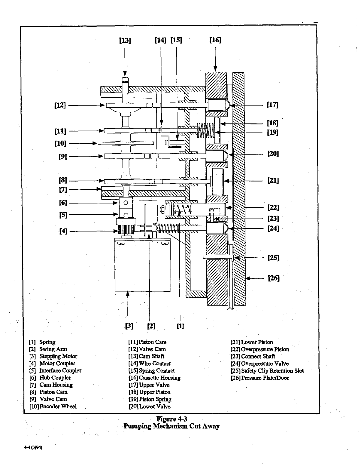
A
[11]
[10]
回
一
[8]
7
——
(61
a
一 ~
[13]
o
[14]
[15]
[16]
|
SE
[17]
[18]
[19]
[20]
[21]
122]
一
一 一
[4]
~
[1]
Spring
[2]
Swing
Am
[3]
Stepping
[4]
Motor
[5]
Interface
|
16]
Hub
[7]
Cam
181.
Piston
[9]
Valve
[10]
Encoder
Motor
Coupler
Coupler
Coupler
Housing
Cam
Cam
Wheel
BI.
[11]
Piston
[12]
Valve
[13]
Cam
-[14]
Wire
[15]
Spring
[16]
Cassette
117)
Upper
[18]
Upper
[19]
Piston
(20]
Lower
Pumping
Pl
Cam
Cam
Shaft
Contact
Contact
Housing
Valve
Piston
Spring
Valve
Figure
Mechanism
MI
4-3
Cut
Away
121]
Lower
[22]
Overpressure
[23]
Connect
[24]
Overpressure
[25]
Safety
[26]
Pressure
[24]
[25]
[26]
Piston
Piston
Shaft
Valve
Clip
Retention
Plate/Door
Siot
4404
Page 47

Pumping
Figure
Cycle
valve
allow
upper
upperpiston
draws
valve
upper
draws
lower
moves
deliverfluid;
overpressure
pistonmonitors
downline
inset.
4-4
Description
valve
upperchamberis
full;
moves
valve
allow
lower
lowerpiston
draws
overpressure
pistonmonitors
downline
in
set.
opens
to
fluid
flow
piston;
back
to
fill;
closed
while
piston
back;
piston
forward
to
pressure
closes
when
forward;
opens
to
flow
to
piston;
back
to fill;
pressure
Section
2.
The
from
the
to
same
push
chamber
.
3.
Once
lower
closes
[18]
‘upper
cassette
beginning
upper
than
stream
patient.
4.
The
opens
point
and
The
result
smooth
patient.
approximately
and-unvarying
delivered
stepped.
4.8
Refer
wheel
The
encoder
which
mechanism.
back
of
:
and
detector
beam
reach
encoder
4.12).
upper
piston
[18]
begins
the
upper
tubing
into
time,
the
lower
forward,
the
piston
and
then
cassette
piston
the
lower
as
of
the
flow
Each
forcing
into
the
lower
upper
piston
[21]
fully
the
lower
begins
to
push
chamber
chamber,
to
lower
of
fluid
the
travel
cycle
of
is
determined
draw
moves
piston
to
valve
[20]
upper
and
repeats.
the
above
of
fluid
full
revolution
1.7
mL
travel
where
backward
be
piston
the
through
of
Encoder
the
tubing
[18]
forward,
valve
downward
forward
draws
forced
closes
lower
cam,
of
fluid
the
by
Wheel
Interrupter
to
Figure
4-3
and
4-6
and
interrupter.
wheel
[10]
is
is
turned
by
the
stepping
The
interrupter
the
cam
arms
produced
the
detector
wheel
housing
by
as
(via
straddle
the
emitter
and
then
it
turns.
to
draw
the
upper
piston
[21]
fluid
in
and
has
moved
the
[20]
opens.
forward
the
lower
to
receive
delivering
back,
out
the
and
the
[18]
reaches
piston
piston,
the
lower
of
the
cam
as
governed
pistons.
the
rate
for
discussion
mounted
motor
assembly
the
I/O
the
encoder
is
alternately
blocked
back
as
fluid
flows
cassette
begins
the
middle
toward
upper
to
force
into the
piston
causing a continuous
lower
upper
[21]
and
tubing
The
at
which
the
fully
valve
The
the
middle
[21]
the
fluid.
fluid
tubing
valve
its
furthest
its
valve
shaft
by
rate
of
the
chamber.
to
slowly
cassette
patient.
back
and
[17]
upper
piston
fluid
in
is
The
more
rapidly
to
the
[17]
forward
furthest
delivers
action
to
the
the
precise
fluid
motor
back,
is
and
of
the
encoder
to
the
cam
shaft
[13],
to
drive
the
pumping
is
mounted
board)
wheel.
by
the
to
so
its
The
allowed
teeth
of
the
emitter
light
to.
the
At
the
the
a
is
Pumping
Figure
Cycle
4-5
Description
Data
from
the
parallel
microprocessor
the
senses
a
check/Turn
result.
alert
the
to
serial
motor
drive
an
incorrect
system
warning
In
this
the
microprocessor
motor
and
interrupter
interface
monitors
pulses
off
manner,
pumping
detector
the
delivered.
response
will
be
then
the
to
mechanism.
is
read
chip
U108
interrupter
If
the
from
the
generated.
encoder
binding,
on'
and
wheel
The
hesitation,
through
on
the
output
microprocessor
pumping
message
insistent
and
the
I/O
board.
in
relation
mechanism,
“System
audio
interrupter
or
stalling
The
to
alarm
of
453/94)
Page 48

4.9
Empty
Refer
to
Figure
tacts.
The
empty
spring
contact,
above
to
the
adjusted
housing.
per
only
of
The
-spring
proper
tension and
with
cycle.
allows
wire
results.
pump’
ground
potential.
cam
housing.
by a set
The
revolution
when
the
metering
upper
[19].
fluid
the
drive
An
empty
the
contact
4-3
bag
contacts
and
alarms.
The
screw
empty
of
the
the
upper
cam,
piston
[18]
Pressure
height
cause
the
cam
fluid
piston
to
fails
to
Figure
Encoder
Bag
for
are
The
bag
pumping
piston
as
caused
(see
(metering
lose
touch
Contacts
discussion
consist
used
in
The
wire
spring
position
located
contacts
is
illustrated
is
loaded
by
Table
upper
piston
cam)
container
contact
the
4-6
Wheel
of
the
empty
of a rigid
detecting
contact
of
on
mechanism.
in
the
to
the
2-1)
or
with
spring
the
contact
(15]
the
spring
the
right side
must
touch
major
in
Figure
the
out
solution
overcome
shaft
to
throughout
inadequate
the
contact,
bag
wire
contact
‘No
flow
[14]
is
connected
is
mounted
contact
of
the
briefly
Contact
depression
5-15.
position
maintain
metering
by a light
container
this
spring
the
pumping
head
cam.
and
an
・
con-
and
to
is
cam
once
occurs
area
and
contact
height
The
alarm
|
transducer
amplifier
range
of 0 to 5 volts.
read
by
the
analog
to
When
an
motor
briefly
overpressure
correct
the
the
WARNING
The
the
overpressure
motor
occlusion
pressure
detect
a
infiltration.
policies
inspect
changes,
2.
Pressure
The
pressure
plate
in
microprocessor
housing
microswitch
within a specified
a
cassette
3.
Photosensor
The
Model
photosensor
adjust
the
photosensor
resistance
resistance
mately
resistor
the
8-bit
1M
cell
analog
4.11
o
See
Figure
is
amplified
which
display
digital
‘Occlusion
backs
condition
cause
is
backing
detection
in
the
and
procedures,
patient’s
and/or
plate
the
door)
regarding
and
pressure
that
is
in
place).
3000
device
LED
display
is a photoconductive
that
varies
varies
ohms.
divider
is
read
to
network,
by
digital
by a two-stage
provides
converter.
of
valve
output
Output
board
off
the
off
voltages
microprocessor
below
before
entering
is
thus
reduced
backpressure. A swing
to
prevent
(see
Section
sensor
administration
In
accordance
operator
infusion
other
Plate
position
provides
activates
distance
and
from
The
the
site
for
signs
of
Position
sensor
information
the
position
plate.
The
when
from
Micro
3100
used
to
monitor
intensities
inversely
approximately
cell
display
converter.
is
designed
and
the
board
with
Overpressure
Swing
4-3
for
Arm
the
following
instrumentation
analog
infiltration.
voltages
from
pump’
hold.
while
reverse
4.11).
detects
set,
but
with
must
swelling,
the
amplifier
via
an
alarm
The
you
arnrcloses”
fluid
flow
downline
is
not
institution’s
periodically
temperature
Sénsor
(housed
sensor
the
the
systems
accordingly.
cell
in
to
the
of
the
cassette
itself
pressure
cassette
ambient
housing
include
light
which
the
display
is
a
plate
has a cell
illuminance.
10K
ohms
into
one
voltage
generated
microprocessor
Valve
discussion.
in
the
are
8-bit
occurs,
designed
The
leg
the
locate
and
while
back-
pressure
board
comes
(when
a
levels
and
The
cell
to
approxi-
of
a
across
via
the
to
and
4.10
1.
Pressure
Occlusion
solid
state
with
the
middle
transducer
activated
voltage
4-6
proportional
(4194)
Sensors
Sensor
pressure
pressure
is a differential
by a constant
and
alarm
transducer
chamber
current
to
applied
conditions
which
of
the
fluid
pressure
source,
pressure.
are
monitored
interfaces
filled
cassette.
transducer
provides
The
output
directly
The
which,
when
an
output
of
by
the
The
overpressure
the
The
coupler
a
The
coupler
off,
the
way.
the
overpressute
piston
cam
housing
toothed
and
swing
while
the
swing
overpressure
In
this
pumping
at
section
is
held
arm
rides on
the
arm
valve
way,
mechanism
valve
[24]
[22].
The
the
rear
of
the
in
ready
the
pump
is
catches
outward
reverse
fluid
backs
is
located
swing
of
the
overpressure
swing
arm
position
toothed
running.
on
the
motor
occluding
flow
off.
directly
arm
engages
by a torsion
surface
When
is
prevented
below
(2]
is
attached
the
of
the
the
motor
coupler
the
fluid
the
valve
shaft.
motor
spring.
motor
backs
and
forces
path-
whenever
to
Page 49

In
the
event
an
excess
pressure
the
pump
will
period,
pressure
situation
valve
4.12
tion.
the
excess
plate
the
pressure
shaft
will
contact
with
the
Backpressure
Refer
to
Figure
Proper
performance
conformity
housing
amount
cassette
overpressure
function
of
providing
great
threshold
The
cassette
position
backpressure
piston,
The
connect
it
joins
movement
During
contact
contains a spring
proper
(which
that
of
and pistons
of
backpressure
to
maintain
valve
together
this
enough
overpressure
overpressure
governs
to
of
the
by
restricting
of
the
shaft
the
connect
between
operation
with
the
force
during
is
applied
the
administration
can
build
up
in
alarm
and
be
maintained
pressure
away
force
pressure
4-3
-
the fluid
[24]
to
necessary
maintain
Low
valve
overpressure
it
provides
piston
[23].
The
the rear
connect
[1]
to
internal
within
from
the
spring
mounted
the
valve
plate
for
discussion
of
the
pump
filled
during
the
is
therefore
the
proper
and
overpressure
regulate
downline
backpressure.
cassette
Occlusion
provides
fluid
flow
valve
is
influenced
and
valve
overpressure
shaft.
This
the
valve
edge
shaft.
which
is
manufacture.
the
overpressure
pressure
set
is
loaded
the
cassette.
the
cassette
cassette
housing.
on
outward,
and
preventing
Regulation
of
backpressure
depends
cassette
and
to
pumping
necessary
cassette
form,
Alarm
backpressure
during
and
are
piston
slot
allows
piston.
of
the
piston
The
piston
precisely
It
is
valve
of
the
improperly,
If
this
happens
on
hold.
During
pushes
In
this
the
overpressure
keeping
.
on
the
cycle. A small
form.
piston
flow
Pressure
yet
it
in
gravity
regula-
constant
cassette
within
The
[22]
for
the
purpose
must
kept
below
Setting.
to
the
operation.
the
amount
by
the
coupled
semi-independent
assembly
calibrated
this
spring
cassette.
The
of
overpressure
by a vertical
is
slotted.
slot
makes
for
force
via.the
shaft)
this
the
flow.
the
|
be
the
where
the
To
avoid
pressure
*
to 4 to 5 psi
alarm
threshold
only
be
used
4.13
The
pole
of
.5
to
1.5
3000
and/or
clockwise
wise
to
remove
4.14
The
Model
modular
to 3 pumps
required.
can
be a Center,
“Center
pump
accept
attachment
ing too
To
2.
3.
many
connect
1.
Attach a pump
attached
Attach
modular
connect
from
the
pump
is in
If
desired,
pump.
To
disconnect
1.
Press
modular
pump
activated
neously
cause a pump
nuisance
setting
occlusion
during
temporarily.
reverts
with
lower
Pole
clamp
is
designed
inches.
to
Modular
connection
The
to
another
connectors,
pumps
either
in
It
Micro
3100
attach
the
the
pump.
3000
and
for
situations
modular
Left,
(pump
of
pumps,
pumps:
to
pole
becomes
pump
either
top
down.
place.
attach
pumps:
disconnect
up
or
when
the
order
to
to
fall.
third
alarms
start
up,
After a brief
to 2 psi.
flow
rates.
Clamp
to
function
will
support
infusion
pump
to
System
Micro
3100
system
which
an
which
when
system
or
Right
is
another
which
IV
pole
Center
to
either
then
slide
by
sliding
Modular
pump
,
down
to
pump
is
prevent
attached
pump.
could
button
disconnect.
lifted
an
in
the
the
pressure
transition
The
Low
with
the
weight
pumps.
the
pole,
are
equipped
allows
multiple
is
mounted
using
side
connector
to
accidental
infusion
designed
pump.
to
This
cause
the
pump.
of
Center
pump
into
from
the
other
side
and
simultaneously
or
lowered
low
occlusion
threshold
period,
setting
should
pole
diameters
of
three
Turn
the
knob
and
counterclock-
with
connection
lines
so
that
any
Only
IV
pole)
will
prevents
IV poles
pole
clicks
The
clamp.
pump:
place.
bottom
to
of
Center
button
simulta-
bump
connect-
to
You
indicate
that
is
the
Model
a
of
are
pump
the
tip.
Pump
align
up,
or
slide
is
only
might
set
up
©
can
Should a small
the
cassette,
rear.
The
The
internal
to
the
decrease
and
engage
tension
internal
The
preloaded
of
the
overcome
However,
higher
the
vertical
pressure
rear
causing
in
pressure
the
to
the
valve.
pressure
pumping
when
the
breakopen
than 1 psi.
temporary
overpressure
shaft
connect
to
overpressure
mechanism
pressure
is
will
less
flow
will
shaft,
This
the
cassette.
pressure
then
also
restriction.
allow
restores
valve
begins.
reaches
pressure
increase
piston
will
disengaged
push
the
the
piston
thus
reasserting
the
opens
The
approximately 1 psi.
varies
occur
be
pushed
from
overpressure
The
resulting
to
move
the
desired
level
as
forward
preload
and
is
within
to
the
the
piston.
valve
forward
spring
of
rotation
force
is
sometimes
Attaching a pump
the
right
and
left
pump
can
then
be
mounted
(Center)
to a pole
modular
attached
pump.
actuates
disconnect
to
either
side
the
buttons
arm
of
lever,
to
retract,
the
pole
causing
A
47694)
Page 50

Electronic
Circuit
Description
4.15
PROM:
LCD:
LED:
NVRAM:
PCB:
SPI:
SRAM:
4.16
Definitions
Programmable
Liquid
Crystal
Light-Emitting
source
that
emits
radiation.
Non-Volatile
Electronic
data
Printed
Serial
serial
Static
write
cally
read/write
even
when
Circuit
Peripheral
bus
interface.
Random
memory
refreshed.
Functional
Diagram
Refer
to
figure
7.1
for
discussion.
Read
Only
Memory.
Display.
Diode. A semiconductor
visible
light
or
invisible
Random
memory
power
Access
is
removed.
Memory.
which
Board.
Interface, a Motorola
Access
which
Memory.
does
not
Electronic
need
to
Block
the
block
diagram
and
system
light
infrared
retains
defined
read/
be
periodi-
。
control
its
_
The
first
peripheral
located
system's
discrete
commands
commands,
information.
an
analog
various
The
located
monitor
receives
regarding
motor
of
disable
alarm.
sor
to
both
sors will
on
the
Display
LCD
panel,
LEDs.
The
from
the
displays
The
Display
analog
to
digital
to
digital
converter
sensor
information
second
peripheral
on
the
CPU/Power
the
motor
information
expected
stepping
an
error,
motor
Under
must
the
central
microprocessors.
communications
Continuous
4.18
rates
the
monitor
stepping
normal
periodically
microprocessor,
problems
also
force
audio
Power
microprocessor,
board
and
is
seven
segment
Display board
central
appropriate
microprocessor
converter
is
microprocessor,
output
of
from
the
fluid
delivery
to
the
microprocessor
and
conditions,
receive
As
with
microprocessor
microprocessor
system
on
the
used
to
to
the
central
Supply
expected
board
the
pump.
central
rates
initiate a Continuous
the
valid
assuring
motor
between
the
pump
into
hold
alarm.
U402
(CPU3),
used
to
control
LED
indicators
and,
from
status
and
also
interfaces
display
rates.
commands
the
board.
gather
and
relay
microprocessor.
U8
(CPU2),
and
is
used
This
microprocessor
microprocessor
and
compares
Upon
detection
has
the
ability
monitor
stepping
microproces-
and
basic
soundness
errors,
two
microproces-
mode
and
is
the
and
receives
these
alarm
to
The
is
to
actual
to
audio
respond
of
initiate a -
The
circuitry
Pumps
as
the
board,
board
logic
as
The
I/O
system’s
interface
display
keypad,
converter
RS232
board
hospital
4.17
The
high
telies
(CPU1),
display
(CPU2). The
microprocessors
Serial
microprocessor(s)
ports. All
output,
cations
for
the
is
organized
CPU/Power
the
I/O
board,
contains
Interface
and
the
well
as
power
board
includes
stepper
circuitry
board
includes
LED
and
for
gathering
handles
host
computer.
primary
motor,
for
LCD
is
System
level
circuit
on a central
with
control
Peripheral
system
system
are
system
two
peripheral
(CPU3)
central
and
Interface
operations,
state
initiated
Supply
piggybacked
data
and
Model
3000
and
Micro
on 4 printed
and
supply
the
the
several.of
the
displays,
miscellaneous
transfer
circuit
board,
the
the
Display
system
and
power
motor
drive
battery
the
interface
and
to
between
boards,
RS232
board.
controller
circuit
charger
system’s
circuitry
an
sensor
the
CPU/Power
Control
design
for
the
Model
controller
and
fail-safe
controller interfaces
all
system
(SPI)
the
microprocessor's
control,
by
the
central
microprocessor,
microprocessors
system
I/O
signals
bus
signals
including
and
data
interprocessor
microprocessor.
3100
referred
Interface
The
and
control
for
circuit,
sensors.
for
analog
to
data.
the
pump
3000/3100
used
monitoring
to
the
using
defined
dedicated
input
Infusion
to
CPU
control
circuits.
the
and
The
the
digital
The
Supply
and
U15
for
peripheral
both
the
on
the
VO
and
communi-
Refer
to
figure
7.2
The
Model
3000
VAC
or
220/240
include a sealed
provide
provides
line
between
the
circuitry
control;
status
AC
RESET.
provides
whenever
4.19
Inputs
keypad
ous
following:
uninterruptable
the
bulk
voltage
+5V
ON,
to
the
primary
DC
voltage
in
the
the
power
indicators
Power
Also, a battery
rapid
AC
power
Interface
to
the
Model
entries
alarm
and
e
Occlusion
e
Battery
+
Ambient
voltage
light
DC,
pump.
charging
by
status
(system
during
and
Micro
VAC
as
lead-acid
system
of
the
power
controlling
and
battery
used
In
addition
supply
to
the
system
Fail
(PFD),
charger
of
is
available.
3000
the
user,
sensors.
pressure)
(for
display
the
description
3100
accept
the
primary
battery
by
electronics
as
operation.
management,
the
supplies,
the
majority
to
microprocessors,
Battery
circuit
the
battery
standard
power
backup
power
voltage
provides
On
(BATT
on
and
of
The
switching
and
of
the
is
-
Description
and
Micro
3100
systems
as
well
as
signals
These
sensors
adjustments)
power
routing.
100/120
source,
supply
converting
the
regulation
activated
monitor
and
to
CPU
board
.
generating
logic
and
several
including
SW),
and
I/O
board
include
from
numer-
the
AC
48994)
Page 51

e
Air
in
fluid
path
e
Motor
encoder
e
Empty
bag
e
Door
position
e
Pressure
e
Safety
Clip
The
primary
pulsing a 12V,
system’s.dual-piston
electronics
information
numeric
4.20
also
via a 2x16
display,
Interconnection
status
plate
position
position
system
4-phase
provide
and
wheel
output
pumping
character
discrete
Summary
The
tables
in
Section 7 specify
three
Model
3000
and
Micro
primary
ribbon
the
.4.21
The
component
multi-layer
volt
4.22
connection
cable
three
boards.
Model
supply
throughout
(SPI)
which
Detailed
3000
and
Micro
technology
design
utilizing
grid,
and
surface
CPU/Power
Board
4.22.1
‘As
shown
schematic, a Motorola
central
expanded-nonmultiplexed
of
external
and
space,
device
System
on
sheet
system
memory
an 8 bit
external
the
microprocessor
and a 2
Control
two
68HC11F1,
control
Kbyte
microprocessor,
through a 16
data
battery-backed
movement
is
fluid
stepper
the
user
3100
carries
motor,
mechanism.
LEDs.
all
the
Design
3100
on
all
PC
an
internal
layers
of
the
CPU/Power
mode
bus.
Using
interfaces
delivery,
which
In
with
alarm
LCD
module,
of
the
connectors
circuit
boards.
system
signals
use
boards.
to
surface
The
ground
for
component
is a 34-pin
and
Supply
Unit
(CPU1)
Supply
U15,
is
configured
so
that
it
can
bit
external
this
external
to a 64
SRAM
achieved
drives
addition,
and
status
an
LED
The
from
mount
boards
layer,
traces.
board
used
as
in
address
address
memory
Kbyte
device.
by
the
on
each
*
area
a 5
the
an
64K
bus
PROM
the
the
of
In
addition
digital
perform a variety
the
following
with
To
provide
(U19)
latch
ADD2
changed,
either a 1
on
the
generated
CPU3SS:
OFFCPU1:
CPU2AR":
SHIDWN:
RTS:
AUDIO1,
circuit
Refer
circuit
specific
are
used
U13, a three-state
provides
signals
sor
4.22.2,
to
the
I/O
bits
(on
page provides a list
description
additional
is
included
outputs
(CPU2)
can
to
correspond
then
the
or 0 on
appropriate
via
this
slave
microprocessor
reset
shutdown
Ready-to-Send
AUDIO2,
to
the
power
(4.22.4),
information
to
control
appropriate
between
and
Motor
SPI
and
be
LDATA
and
the
relevant
(CPU2)
The
CPU/Power
microprocessor,
lar
to
verify
at
the
appropriate
with
CPU1
processors,
status
or
state
provide
signals
necessary
are
U8,
that
the
primarily
with
seven
information
defined
interface,
ports
A,
E,
of
sensing
pin
location.
I/O
signals,
on
the
CPU/Power
modified
to
the
latch
selected
latch
latch
select
signal
control
those
buffer
latch
and
(WRDIS1
include:
for
for
signal
and
AUDIOS:
unit
the
display
on'how
elements
on
the
multiplexing
on-board
off-board
Monitor
Supply
used
system
rate.
The
through
additional
system
as
follows:
board
to
stepper
microprocessor
between
backup
the
24
general
and
G) on
CPUI
and
control
by
is
strobing
Display
control
audio
for
RS232
(4.22.6),
control
these
CPU/Power
motor
tasks.
of
these
signals,
an
8-bit
addressable
Supply
setting
ADDO, ADD1,
output
which
changed
the
for
U19).
board
power-down
monitor
RS232
components
signal
drive
signals
audio
unit
additional
of
the
system.
of
SPI
and
monitor
circuitry.
board.
by
enable
Output
microprocessor
circuit
(4.24.2)
control
supply
I/O
microproces-
Microprocessor
includes a 68HC705C8
monitor
the
SPI
I/O
control.
CPU1,
motor
the
and
is
being
communicates
port
on
both
lines
used
microprocessors
The
purpose
are
used
Table
4-1
along
The
is
to
be
placing
pin
low
signals
signal
for
audio
・
control
for
bits
board,
address
in
particu-
stepped
micro-
to
relay
seven
I/O
to
on
latch
and
As
mentioned
used
to
microprocessor
and
also
functions.
called
MOSI,
block
diagram
tions
between
modules
unit,
motor
above,
provide
provides
The
signals
SCK,
in
the
of
the
monitor
communications
and
pump
unit.
the
Serial
the
two
peripheral
an
interface
associated
MISO,
Section
System
microprocessor
and
7,
the
Control
system:
Peripheral
between
microprocessors,
for
various
with
this
SS".
As
illustrated
SPI
is
used
Unit
and
keypad
unit,
and
Interface
the
central
system
interface
for
communica-
the
following
display
the
switch
(SPI)
I/O
are
in
the
control
sensor
is
Inputs:
- e (PAO)
e
(PAI)
e
(PAZ)
e
TCAPCPUIMS
Outputs:
e
CPU2
e
OFFCPU2,
(PBI)
e
CPU20DS,
CPUI
Data
CPUI
Data
CPUI
Data
AUDIO,
signal
motor
.
(IC3)
(02)
(1C1)
motor
“step”
initiates
backup
to
allow
battery
enable/disable
signal
from
audio
On/Off
signal
CPU1
alarm
switch
(PBO)
49084
Page 52

Table
Signal
AC
PNL
CTS
AUX
AUDIO
BAT
ON
ADDO
ADDI
ADD2
WRDIS1
LDATA
RAMB1
RW
Name
ON
LOCK
OK
SW’
KEY
4-1:
ON
Miscellaneous
Description
Active
Toggled
the
pump.
Pulled
cations
Low
when
available
Batt
fuses
Active
generated
Active
and
power
Active
Address
display
Address
display
Address
display
Latch
Latch
SRAM
Output
connected
BACKUP
CPUIMS'
MTRSTRB'
PFD’
SENSTRB
KYSTRB
AUDIO
Audio
MotorStep.
stepping
MotorStrobe.
motor
Active
SensorStrobe.
rea
KeyStrobe.
I/O
when
low
high
or
low
high
by
R58.
interface
there
is
whenever
are
functioning
high
when
is
acceptable.
low
when
is
turned
high
when
line O for
boards.
line 1 forthe
boards.
line 2 for
boards.
control
data
line
enable
enable
to
CPU1
signal
Inverted
pulse.
step
pattern.
low
upon
Inverted
signal
for
control
control
from
Inverted
Inverted
Signals
plugged
is
unit
the
with
the
Clear-to-send
(SCT).
auxiliary
the
the
the
on.
the
the
the
for
the
battery
battery
correctly.
audio
unit
unit
is
being
On/Off
extended
extended
extended
the
extended
extended
from
CPUS.
for
EEPROMI
(U15).
CPUI
to
the
by
U14
by
U12
AC
power
failure
by
U14
by
U12
on
System
into
Keypad
signal
power.
is
switched
determines
powered
key
on
control
contro!
control
control
audio
to
become
to
become
to
to
become
to
become
Control
power.
AC
Lockout
for
use
Auxiliary
on
and
that
by
the
keypad
bits
on
bits
on
bits
on
control
bits
bits
on
(U17)
and
unit.
CPU1MS
MTRSTRB
interrupt
SENSTRB'
KYSTRB'
Unit
Button
on
by
the
serial
battery
the
battery
the
alarm
its
rechargeable
is
being
U19
and
the
U19
and
the
U19
and
on
U19.
U19.
SRAM
for
high
for
CPU.
for
for
keypad
(U15)
the
back
of
communi- | PE2(63)
power
is
and
Aux
being
battery
pressed.
I/O
and
I/O
and
the
Vo:
and
(U18)
which
is
side
motor
strobing
YO
sensor
reads.
Pin
PEO
PEI
PE3
PE4
PES
РЕб
PGO
PGI
PG2
PG4
PG3
PG6
R/W'
PAT
PA6
PAS
XIRQ
PGS
PAA
on
CPU1
(59)
(61)
(65)
(60)
(62)
(64)
(27)
(26)
(25)
(23)
(24)
(21)
(5)
(35)
(36)
(37)
(18)
(22)
(38)
(U15)
4106/99)
Page 53

The
motor
monitor
periodically
fluid
delivery
this
information
CPU2
continually
steps
the
motor)
interval
match
motor
alarm
similar
from
Additional
microprocessor
used
allows
the
controls
to
the
within a given
by
driving
by
driving
alarm
CPU1
output
by
the
the
unit
case
of a failure
the
software
receive
within a defined
power
power-down
information
rate
of
calculates
monitors
and
expected
CPU2ODS
CPU2
condition
signals
include
control
to
be
of
CPU2.)
4.22.3
The
battery-backed
compatible
contains a real-time
deselect/write
carbon
The
(write
The
(changing
of
the
250
The
E
inputs
the
A
write
WRTENBL
throughout
nanoseconds
The
when
part
until
‘Only
contents
4.22.4
The
of 3 of
function
Nonvolatile
nonvolatile
mono-fluoride
SRAM
enable)
device
2048
nanoseconds
SRAM
latter
is
G/OUTPT
reading
will
the
CPUI
audio
the
memory
SRAM
with
protection
is
in
pin
architecture
addresses
address
is
in
are
held
occurring
terminated
or
E.
the
cycle, A complete
from
pin
from
remain
G/OUTPT
in
the
of
the
SRAM.
Audio
unit
schematics
CPU/Power
of
the
audio
standard
read
is
from
write
low.
falling
The
address
is
the
in a high-impedance
system
design
regarding
the
pump
via
the
an
expected
the
CPUIMS
compares
error
powered-down
CPU1.
the
step
rate.
tolerance,
low
AUDIO
if
OFFCPU2.
low.
it
fails
time-out
generated
circuit
(CPU1
of
the
system
actual
If
and
to
(section
requires
the
receive
by
OFFCPU2
via the
that
the
expected
SPI
bus,
and
motor
step
signal
motor
two
values
CPU2
will
will
initiate
CPU2
will
communications
period.
the
motor
is a signal
4.22.6)
On/Off
software
normally
independent
CPU2
(which
step
disable
an
initiate
monitor
which
Memory
on
the
CPU
board
is a Mostek
(U18),
which
is
pin
and
function
2Kx8
SRAMs.
clock, a crystal, a power-fail
circuit,
battery.
mode
high
allows
without
locations. A complete
address
mode
The
by
the
addresses
an
output
SRAM.
pin
is
and a long-life
whenever
and
the E
ripple-through
removing
valid
whenever
start of a write
edge
of
earlier
must
valid
to
enable
The
brought
control
Circuit
are
on
Supply
circuit
board
is
to
This
device
chip
lithium
the
WRTENBL
(chip
enable)
chip
to
valid
the
either
WRTENBL
rising
be
held
write
cycle
end
of
that
data
I/O
(tri-stated)
low.
unit
may
the
lower
schematics.
provide a fail-safe
pin
access
enable)
read
cycle
output.
WRTENBL
is
referenced
edge
of
valid
takes
write.
is
used
pins
on
condition
read
or
half
of
from
rate.
do
not
audio
key
of
also
is
to
any
takes
or
250
only
the
write
sheet
The
alarm
the
a
in
low.
and
to
E.
the
1
system
system
alarm.
electric
fail-safe
audio
phone
the
The
circuits
Audio
such
will
This
transducers
design
alarm
to
monitor
primary
audio
unit
according
e
Audio
e
Sound
e
Audio
e
Emergency
Driving
Audio
alarm
is
controlled
(U16).
This
AUDIOZ,
provide
initiate
outputs.
Based
outputs:
FREQ
ENV
These
inverting
to
the
JP11
tone
Sound
The
quality
circuit
voltage
ated
Audio
The
microphone
audio
amplified
stage
from
verified
“counting”
signal.
sounding
condition
and
commands
insistent,
on
those
OUT:
OUT:
outputs
buffer
primary
are
included
sequences.
Shaping
sound
to
the
does
to
the
discrete
Verifier
audio
verifier
signal
and
binary
U11
(AUDIO
the
If the
and
will be
that
if
the
primary
detect
the
failure
is
accomplished
with
uses
one
signal
and
uses
the
primary
alarm
fails.
may
be
divided
to
their
driving
shaping
verifier
circuit
circuit
circuit
oscillator
Circuit
generation
by a MicroChip
device
AUDIOS.
three
are
(U9)
audio
on
receives
to
the
non-insistent,
inputs,
frequency
On/Off
coupled
to
provide a differential
speaker.
to
provide
Circuit
shaping
between
circuit
tones
generated
this
by
exponentially
inverting
components.
Cireuit
buffer
circuit
to
listen
to
tones
is
coupled
fed
ripple
presence
system
AUDIO
to
to
the
counter
OK)
(at
512
expects
OK
detected
alarm
fails,
and
generate a Back
through
independent
transducer
the
functions:
circuit.
the
the
Together,
audio
the
pulse
envelope
through
the
is
used
the
use
drive
to
provide
second
alarm
into
Model
PIC16C54
Jumpers
on
(U9)
as
both a micro-
and a backup
the
following
3000
microcontroller
following
microprocessor
and
device
to
option
to
primary
decreasing
inputs:
these
three
key-click
provides
drive
for
speaker
transistors
JP2, JP5,
of
give a resonant
speaker
at
the
end
uses a secondary
generated
this
circuit
FYT
input
with
goes
high
speaker
and
1023
the
remains
by
the
by
using
of
U11,
oscillator.
when
the
A)
of
an
cycles
by
primary
system
speaker
low, then a fault
controller.
the
secondary
Up
audio
of
two
piezo-
circuitry.
and
the
selectable
the
The
the
primary
speaker
sub-
Micro
AUDIO1,
signals
required
audio
two
speaker
signal
and
an
drive
signal
JP6
and
alarm
“bell”
A.
The
supply
of
each
speaker B as
speaker
C20
which
The
audio
A.
and
is a 14-
Q9
output
circuit
has
signal
the
audio
to
be
then
Once
if
3100
to
a
The
by
.
4-11
(3/94)
Page 54

the
AUDIO
CPU2AR’
be
again
read
by
low
(reset)
Emergency
If a system
circuit
The
two
and
BACKUP.
counter
OK
signal
sampled
CPU1
by
Oscillator
fauit
is
designed
signals
with
oscillator
tine
(active
and
on
PE4
CPU1
is
detected,
to
which
AUDIO".
Speaker B whenever
4.22.5
The
be
powered
sealed
up
supply,
operation.
220-240
operation,
inserted
requires
and
range.
describes
power
switching
protection
As
on
each
boards
blocks.
CPU/Power
+18V
voltage
generate
boards
generates
Power
Model
lead-acid
providing
The
VAC,
fuse
and
removal
F2
with
Sheet 3 of
the
is
converted
regulator
(U23).
shown
in
of
the
to
meet
Primary
supply
when
the
for
general
the
3000
and
primarily
battery
power
selected
F1,
jumper
of
appropriate
the
primary
Section
three
the
power
DC
Supply
when
AC
power
+5V
supply
logic
+5V
supply.
4.22.6 | Power
The
responsibility
the
top
half
Off
switching
signals
control
The
indicating
circuit
primary
microprocessor
operating
to
the'system’s
pump
The
is
turned
Model
on
continually
of
of
sheet 1 of the
of
the
the
does
intent
controlled
battery
non-volatile
on
and
3000
and
monitors
is
set
high,
it
must
be
low)
before
the
verified.
and
via
the
U19
The
AUDIO
CPU2AR"
pin
11.
Circuit
the
emergency
be
activated
feed
The
to
produce a fixed
drive
this
circuit
circuit
signal
by
either
are
uses a 14-bit
is
activated
Supply
Micro
3100
electronics
from
AC
Mains
voltage,
is
included
approximately 6 hours
operates
by
SW1.
specified
JP7
is
shorted.
JP7
(open)
ratings
CPU/Power
power
to
+18VDC
(U22)
with
7,
DC
supply
Model
3000
requirements
power,
board
AC
labéled
and
power
is
not
which
circuits,
Control
the
power
battery
state
of
not
directly
of
the
power
power-down
to
ensure
off
by
Micro
On/Off
in
the
on
either
For
100-120
for
110-120VAC
220-240
and
insertion
for
the
higher
Supply
supply
circuit;
through a diode
overvoltage
voltages
and
Micro
V+,
is
taken
from
is
applied
available.
is
used
on
U2, a switching
control
schematic,
supply
and
system
memory
the
3100
presses and
turn
control
that
status
central
central
power.
the
at
reset
using
the
audio
signal
may
OK
signal
is
signal
is
strobed
oscillator
CPU1
or
CPU2.
CPU2
AUDIO"
ripple
freguency
tone
(low).
are
intended
however
pump
as a back-
of
pump
100-120
VAC
VAC
or
operation,
operation
of
fuses
F1
voltage
board
schematic
where
line
bridge
and
“crowbar”
are
generated
3100
circuit
of
individual
is
generated
either
or
the
V+
is
all
circuit,
is
to
control
to
generate
The
pump
circuit
of
the
data
power-down.
microprocessor.
microprocessor
activates
the
battery
used
three
circuit
regulator,
shown
logic
power
on
and
is
to
device
can
be
the
circuit
on
to
on
the
off.
allow
when
written
The
on
to
a
is
the
On/
displays,
ate
power
the
AC
system
power,
state,
ceasing
On/Off
keypad,
to
turn
the
pump
is
supplied
central
microprocessor.
power,
the
microprocessor
status
during
the
microprocessor
disconnecting
active
system
control
is
and
by
determined
including:
e
OFFCPUI - control
battery.
@
OFFCPU2 - control
battery
e
ON/OFF - signal
©
BAT.
SW - signal
generated
The
BATT_
control
connects
Components
the
battery
which
is
tions
to
to
the
battery
To
switch
occur.
The
through a resistor
voltage
and
VBatt
“ON”
while
does
not
provide
from
the
power
to
when
removing
is
in
the
battery
On/Off.
low
will
high
connecting
The
design
battery
norma]
from
SW
signal
circuit
and
the
battery
U3
and
switching
always
+18V,
energized
Vbatt,
via a second
the
battery
SET
pin
is
“on”
whenever
are
both
the
+18V
require
back-up
pump
current
battery
so
control
system
AC
“OFF”
state.)
“ON”
echoes
Toggling
toggle
the D flip-flop
the
also
includes
“OFF”
(disconnecting
operation,
is
bridge
that
the
the
processor 1 asserts
to
the
RESET
BATT_SW
microprocessor
+18V
supply
the
flip-flop
remain
“OFF”
pin
on
signal
low.
attempts
is
energized,
will
be
high. A second
allows
either
other
active
“on”.
Whether
AC
or
battery
When
runs
both
“on”
and
runs
only
the
battery
functions
from
used
above
is
used
to
the
U4
and
supply
(displays,
by
several
signal
from
signal
from
On/Off
to
connect/disconnect
signals
the
primary
to
control a switch
main
system
are
used
are
powered
through
and
AuxBatt
fuse).
“ON”,
one
of
on
the D flip-flop
and
ensures
+18V
is
diode
coupled
(AC
generated)
from
the
battery.
power
whenever
the
system
power-down.
power
from
the
The
other
method
the
system
On/Off
“ON”
signal
and
battery
to
two
V+.
methods
the
battery
the
the D flip
high
is
OFFCPU1
It is
important
to
disconnect
both
and
the
method
disconnected
flop
SET
BATT_SW
for
microprocessor
functions
the
affects
the
continually,
“off”
main
the
pump
states.
during
when
appropri-
source
behavior
is
plugged
tracking
On
system
immediately
etc.).
logic
signals
PI
to
disconnect
P2
to
disconnect
key
on
front
panel
output
of
the
(Q2)
which
power
voltage,
to
generate
diode
(a
secondary
two
that
applied.
to
V+,
microprocessors
pump
while
the
battery
signal.
and
and
the
by a supply
coupled
connection
logic
events
is
connected
the
battery
Because
switching
supply
(This
is
It
does
+18V
is
is
necessary
when
of
switching
sequence
connected
the
of
BATT_SW
BATT_SW
for
switching
from
V+).
when
This
signal
forces
the
to
note
that
the
battery
RESET
logic
voltage
connec-
however
removed
have
will
if
while
pins
signal
switching
to
the
battery
disconnect
of
of
in to
battery
“on”
after
battery,
power
V+.
for
must
to
+18V
+18V
VBatt
pump
the
pressing
is
go
the
Under
micro-
is
tied
the
the
on
will
the
.
4-12
(3/94)
Page 55

battery
microprocessor
processor,
OFFCPU2
battery
toggled.
The
OFF
BATI_SW
BATI_SW
under
system
detects a potential
the
monitor
signal.
to
be
disconnected
following
switching
The
power
power
status
è
PFD' - indicates a power
voltage
@
AUX_OK’ - indicates
.
active
e
RESET”-
supply
e
AC_ON - indicates
4.23
The
YO
sensor
interface
charger
on
the
CPU
quad
flip-flop
interface
logic
logic:
on — off = (OFFCPUI
or
(OFFCPU2
off — on = ON/OFF
control
signals:
supply,
low
main
is
<4V
I/O
board
includes
circuit.
I/O
board
device
are
provided
(U105).
4.23.1
The
system
coils
commands
of
the
pulse
board
while
signal
signal.
To
step
motor
PHASE
assuming
appropriate
chosen
connector
Motor
motor
control
controller
of
the
system’s
to
U106
four
coils.
(CPU1MS”),
initiates
CPU2
and
must
all
monitors
enables/disables
the
motor,
be
energized
B,
PHASE
that
the
phase
coils
to
ground
P103.
fault
conditions.
microprocessor
Once
asserted,
when
equations
and
or
circuit
also
active
low
power
system
or
>6V,
AC
reset
active
Board
motor
circuitry
to
These
motor
To
and
drive
signals
and
gated
(U106).
via a parallel
Control
circuit
on
independently
stepper
to
generate
signals,
initiate
the
CPU20DS
signals
motor
stepping
motor
appropriate
by
C,
and
connects
through
step
the
If
the
fault
in
will
this
signal
the
ON/OFF
summarize
and
ON/OFF
+18Vhigh
generates
fail
power
control
connector,
through a 74HC
I/O
the
motor.
pulse
on
the
on
the
signal
active
low
connected,
and
for
the
motor
signals
to
serial
I/O
board
drive
The
“On/Off”
in
conjunction
motion.
through
stepping
the
asserting
motor
coils
via
with
or
signals
PHASE D in
SIGNAL
transistors
motor, a step
is
the
negative
motor
monitor
the
main
micro-
exert
its
then
allows
signal
is
the
battery
+18V
and
the
following
V+
main
AUX_BATT
drive
and a battery
173
to
the
shift
allows
each
CPU
signals
CPU1
its
YO
the
the
phases
the
correct
low.
Q107-Q110
pulse
ON/
low)
+18V
system
when
+5V
active
low
circuits,
ate
generated
3-state
sensor
register
the
of
the
four
board
sends
for
each
with a step
on
the
data
bus
CPU1MS’
CPU20DS
of
the
PHASE
pattern,
Asserting
side
of
signal
the
low)
line,
CPU
A,
the
the
and
approximately
U107
which
through
positive
provide
position.
circuit
as
ing
the
motor
drive
transistors,
the coils
For
full
energized
AB-BC-CD-DA
For
half-step
energized
Smsec
connects
transistors
side
“holding”
Zener
it
limits
allowing
step
coils
Q111-Q113.
of
the
coils
current
diode
the
coils.
This
but
also
for
operation,
is
:
(two-phase
operation,
coils
is
:
long
the
positive
are
necessary
D107
fly-back
not
rapidly dissipates
increased
the
the
AB-B-BC-C-CD-D-DA-A
4.23.2
The
provides
the
following switches
door
detector. A 10-pin
switches
the
sensors
parallel
cated
MISO.
Interrupter
The
used
photodetector
pump
45°
encoder's
output
immediately
encoder
from
U13
P200.
Air
An
air
bubbles
energized
system
output
entirely
beam
output.
flip-flop,
Switch
switch
sensing
information
switch,
interrupter
to
of
on
Detector
empty
and
sensors
is
read
to
serial
to
the
system
Detector
detect
rotation
device
camshaft
motor
rotation.
light
signal
is
deactivated.
is
generated
CPUI
I/O
the
CPU/Power
detector
in
the
periodically
controller
signal
is
through
is
refracted
The
output
U103,
detector
and
source
read
signals.
opto-encoder
fluid
normally
Sensor
unit
(U105
to
the
and
bag
switch,
connector,
to
the
by
the
system
interface
to
fluid,
at
so
chip,
control
is
of
the
straddles
produces
To
conserve
is
energized
by
the
The
by
U101,
CPU1
Supply
path.
The
and
determine
high
however
the
air/fluid
of
the
opto-encoder
that
very
is
asserted
normally
is
important
only
proper
through
side
Between
to
voltage
prevents
switching
sequence
“wave”
proper
sequence
Interface
and
associated
system
sensors:
I/O
through
an
system
the
control
interrupter
clamp
P102,
is
board.
control
Ui05.
SPI
opto-encoder
pump
camshaft.
an
encoder
signal
transitions
power,
immediately
control
control
an
8-bit
communicates
interconnected
device
is
light
source
output
if
air
bubbles
when
the
when
interface
brief
signals
U101
of
all
coils
motor
steps,
connected
keep
to
created
to
the
motor
the
motor
after
damage
the
energy
speeds.
of
“on”
drive)
of
“on”
components)
unit
concerning
detector,
switch, and
used
to
connect
Data
from
unit
through
Data
is
communi-
signals
signal
addressable
used
signal
air
is
SCK
device
An
wheel
within
the
opto-
before
unit
and
for
the
to
U108
at
to
detect
in
the
read
exist,
light
source
is
present,
producing a low
latched
can
be
and
to
+10V
the
+5V
to
in
drive
switch-
to
the
in
or
.....
or
air
the
each
of
the
and
which
is
LED/
on
the
every
the
then
opto-
latch
via
P101/
air
device
is
by
the
The
passes
the
light
by a D
detected
4-13
(3/94)
Page 56

{possible
Once
system
from
Switch
The
following
DOOR
activated
CLAMP
activated
EMPTY
pumping
cassette
These
input/control
output
for
small
set,
the D flip-flop
control
U108
pin
Sensors
I/O
board
switches:
SWITCH: | coupled
when
SWITCH: | coupled
when
BAG: _ positioned
mechanism
switches
data
from
unit
12
also
the
clamp
are
and
air
bubbles
by
asserting
to
the reset
provides
door
is
and
all
coupled
signals
U105
pin
and/or
high
(U103)
is
inserted
must
be
the
AIR_RESET
line
of
U103.
the
circuit
to
the
door
open
to
the
free-flow
in
the
upper
indicates a lack
to
the
system
on
U108
pins
13.
flow
rates.)
cleared
interface
handle
clamp
portion
of
fluid
controller
5,6,
and
7,
by
the
signal
for
the
and
and
of
the
in
the
and
via
serial
'
4.24
The
Display
functional
segment
©
sensor.
(CPU1)
bus
and
from
the
pressure,
segment
user.
The
the
user.
The
display
unit
on
tor
(P401).
Keypad
Display
Board
blocks:
display
They
on
SPI
user.
ambient
display
LCD
the
unit
keypad
unit,
are
interfaced
the
CPU/Power
interface
The
light
unit
unit
board
communicates
CPU/Power
Modules
Board
can
be
broken
unit,
LCD
unit,
to
the
Supply
cable.
The
analog
sensor
level,
and
provides
provides
incorporated
numeric
alphanumeric
Supply
down
analog
and
pressure
system
Board
keypad
unit
senses
cassette
with
board
via a 34-pin
into the
into
five
major
sensor
unit,
7-
plate
control
unit
information
the
unit
via the
main
provides
battery
position.
information
system
display
control
connec-
board
position
YO
input
level,
The
7-
to
the
to
are:
4.23.3
U109, a Unitrode
for
use
necessary
cycles
both
separate
controlled
state,
with
battery
"
At
power-up,
current)
charging
battery
battery
point,
battery
charge
(oct)
mode
(Vf)
battery
If
the
three-phase
Battery
with
sealed
circuitry
for
the
12
the
charging
charge
over-voltage
The
circuit
sequenced
capacity
the
state
and
current
voltage
voltage
the
battery
at a constant
current.
in
overcharge
and
enters
to
the
battery.
voltage
battery
voltage
charging
Charger
UC3906,
lead-acid
to
volt
output
states: a high-current
uses
current
and
device
supplies
to
the
and
exits
increases
enters
When
float
In
and
attempts
is a battery
batteries.
optimally
battery.
voltage and
state,
current
and
voltage
life.
enters
approximately
battery.
bulk
above
the
overcharge
14.7
volts
the
charge
mode,
the
mode,
applying a constant
float
mode,
to
is
drawn
sequence
contro}
This
IC
monitors
current
bulk-charge
and a precision
and
voltage
control
the
bulk
The
chip
charge
mode
14.0
volts
(Voc)
and
current
charger
the
charger
maintain
below
12.4
will
begin
charger/controller
It
contains
the
sensing
charge
180
monitors
mode,
monitoring
drops
exits
this
again.
all
of the
charge
and
and
controls
through
float-charge
to
three
state,
combined
maximize
(constant
mA
(Imax)
the
when
the
(V12).
At
this
charging
the
below
50mA.
overcharge
13.8
monitors
float
voltage.
volts
(V31),
hold
a
of
the
volts
the
the
Analog
7-Segment
Multiplexed
LCD
Pressure
4.24.1
The
the
alternately
examining
column
Sensor
e
Pressure
e
Ambient
e
Low
«
LED
©
+8V
e
Display
@
Segment
«
Digit
display
e
Buffer
e
Contrast
e
EL
Backlight
16-pin
keypad
of
Battery
Segment
Regulator
Decoder/Latch
Plate
Keypad
keypad
unit's
enabling
the
the
Unit
Sense
Light
Detect
Display
Control
LED
Latch
Adjust
Position
connector
circuitry.
status
button
Differential
Sensor
Voltages
and
A/D
reference
Unit
Unit
Display
Sensor
Unit
(J403)
The
each
of
the 4 rows
of
the 8 columns
that
is
being
Amplifier
connects
keypad
to
pressed.
voltages
the
may
be
scanned
of
the
keypad
determine
keypad
by
and
the
row/
to
The
charging
proportional
has a temperature
compensation
the
charger
‘charging
perature range.
additional
4-14
(3/94)
voltages
to
an
of
circuit
should
(Refer
details
most
be
invoked
internal
coefficient equal
battery
is
located
optimized
to
concerning
by
voltage
manufacturers,
near
the
through
the
Unitrode
the
battery
the
charger
reference.
to
the
battery,
the
IC
circuit are
This
recommended
and
battery
expected
Databook
charging
reference
assuming
tem-
for
chip.)
To
select
the
CPUI
sends
selecting a row
pulled
high
by a 47K-ohm
row
that
is
to
other
rows
should
After
selecting
row
of
the
the
appropriate
via
U410.
be
examined
be
selected
the
row
keypad
command
Since
resistor
should
to
be
examined,
that
is
the
network
be
high.
to
be
over
column
(RP
selected
the
examined,
the
SPI
bus,
inputs
are
401),
low
and
columns
may
the
the
be
Page 57
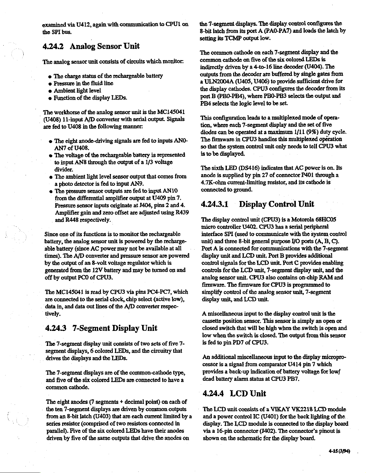
examined
the
SPI
bus,
4.24.2
The
analog
e
The
charge
e
Pressure
e
Ambient
e
Function
The
workhorse
(0408)
are
fed
e
The
11-input
to
eight
AN7
e
The
voltage
to
input
divider.
e
The
ambient
a
photo
e
The
pressure
from
Pressure
Amplifier
and
R448
Since
one
battery,
‘able
times),
by
generated
off
The
are
data
tively.
the
battery
The
the
output
by
output
MC145041
connected
in,
and
4.243
The
7-segment
segment
drives
the
The
7-segment
and
five
common
The
eight
the
ten
7-segment
from
an
series
resistor
parallel).
driven
by
via
U412,
again
with
Analog
sensor
in
light
of
U408
anode-driving
of
U408.
ANS
detector
the
differential
sensor
of
its
analog
(since
A/D
of
from
PCO
data
7-Segment
displays, 6 colored
displays
of
the
cathode.
anodes
8-bit
Five
five
Sensor
unit
consists
status
of
the
the
fluid
line
level
the
display
of
the
A/D
in
the
of
the
through
light
sensor
gain
and
respectively.
functions
sensor
AC
converter
an
8-volt
the
12V
of
is
read
to
the
out
LEDs.
analog
converter
following
rechargeable
the
level
sensor
is
fed
to
outputs
amplifier
inputs
originate
zero
is
unit
power
and
voltage
battery
CPU3.
by
CPU3
serial
clock,
lines
of
Display
display
displays
six
latch
(comprised
of
of
unit
and
the
LEDs.
are
colored
(7
displays
the
the
LEDs
segments + decimal
are
(U403)
six
colored
same
that
of
outputs
communication
Unit
of
circuits
rechargeable
sensor
with
manner.
signals
output
input
are
offset
to
monitor
is
powered
may
pressure
regulator
and
via
chip
the
A/D
unit
is
serial
are
fed
battery
of a 1/3
output
AN9.
fed
to
output
at
J404,
are
adjusted
the
not
be
sensor
may
be
pins
select
converter
which
battery
that
at
by
available
PC4-PC7,
Unit
consists
LEDs,
of
of
two
and
the
the
common-cathode
are
connected
driven
by
are
each
two
resistors
LEDs
have
that
drive
point)
common
current
to
CPU1
monitor:
the
MC145041
output.
input
Signals
to
inputs
ANO-
is
represented
voltage
comes
from
AN10
U409
pin
7.
pins 2 and
using
rechargeable
the
are
which
tumed
(active
respec-
sets
of
circuitry
to
on
4.
R439
recharge-
at
all
powered
is
on
and
which
low),
five
7-
that
type,
have
a
each
outputs
limited
connected
their
the
in
anodes
anodes
on
of
by
on
the
7-segment
8-bit
latch
from
setting
its
TCMP
The
common
common
indirectly
outputs
a
ULN2004A
the
cathode
driven
from
display
port B (PBO-PB4),
PB4
selects
This
configuration
tion,
where
diodes
can
The
firmware
so
that
the
is
to
be
displayed.
The
sixth
LED
anode
is
supplied
4.7K-ohm
connected
4.24.3.1
The
display
micro
controller
interface
unit)
Port A is
display
control
controls
analog
firmware.
simplify
display
A
cassette
closed
low
is
An
cessor
provides a back-up
dead
SPI
and
three
connected
unit
signals
for the
sensor
control
unit,
miscellaneous
position
switch
when
fed
to
pin
additional
is a signal
battery
4.244
*
The
LCD
a
and a power
display.
via a 16-pin
shown
The
on
displays.
its
cathode
the
(U405,
cathodes.
the
logic
each
be
operated
in
system
(DS416)
current-limiting
to
ground.
Display
control
(used
8-bit
and
for
LCD
unit.
The
firmware
and
that will
the
switch
PD7
miscellaneous
alarm
LCD
unit
consists
control
LCD
connector
the
schematic
The
display,
port A (PAO-PA7)
output
low.
on
each
on
five
of
the
by à 4-to-16
decoder
7-segment
CPU3
by
are
buffered
U406)
to
CPU3
configures
where
PBO-PB3
level
to
leads
to a multiplexed
display
at a maximum
handles
control
unit
indicates
pin
27
of
resistor,
Control
unit
(CPU3)
U402.
CPU3
to
communicate
general
for
LCD
the
CPU3
of
the
LCD
input
sensor.
of
CPU3.
from
indication
status
purpose
communications
unit.
Port B provides
LCD
unit.
unit,
7-segment
also
for
CPU3
analog
unit.
to
the
This
be
high
is
closed.
comparator
at
CPU3
Unit
of a VIKAY
IC
(U401)
module
is
(J402).
for the
control
7-segment
six
colored
line
decoder
provide
selects
be
set.
and
this
multiplexed
only
needs
that
connector
and
configures
and
loads
display
LEDs
(U404).
by
single
sufficient
the
decoder
the
mode
the
set
1/11
(9%)
to
tell
AC
power
P401
its
cathode
Unit
is a Motorola
has a serial
Port C provides
contains
sensor
display control
sensor
when
The
input
of
battery
for
connected
The
display
peripheral
with
the
I/O ports
with
additional
display
on-chip
is
programmed
unit,
7-segment
is
simply
the
switch
output
from
to
the
display
U414
pin 7 which
voltage
PB7.
VK2218
the
back
to
the
connector’s
board.
the
latch
and
is
The
gates
drive
from
output
of
opera-
of
five
duty
operation
CPU3
is
on.
through
is
68HC05
system
(A,
B,
the
7-segment
control
enabling
unit,
and
RAM
to
unit
is
the
an
open
is
open
this
sensor
micropro-
for
low/
LCD
module
lighting
display
pinout
the
by
the
from
for
its
and
cycle.
what
Its
a
C).
the
and
or
and
of
the
board
is
415
3/94)
Page 58

A
5K-ohm
“divider
the
input
The
hours.
display
option
backlight
which
LCD
of 0 -
manufacturer
The
life
will result
potentiometer (R402)
regulates
module.
1.7
volts.
backlight
progresses,
option
the
The
contrast
specifies
may
and
in
early
display
only
when
voltage-controiled
the
be
continuous
required.
is
used
is
controlled
life
of
the
noticably
replacement.
to
adjust a voltage
contrast
by a voltage
display
dimmer
use
of
the
at
as
the
backlight
Use
of
3000
the
4.24.5
This
sensor
position
‘the
that
specified
cassette
board
of
pump’s
activates
is
at
P403.
4.25
The
RS232
daughter
Supply
connected
the
transmitted
received
provides
hardware
Ground,
board
back of
Pressure
provides
the
cassette
mechanical
when
the
distance
in
from
place).
RS232
Interface
board
which
via
connector
to
the
external
the
pump.
by
CPU1
RS232
level
1500V
isolation
port
consists
and
hardware
Plate
information
housing
system.
pressure
the
The
switch
Position
regarding
and
pressure
The
sensor
plate
cassette
housing
connects
comes
Interface
is
physically
is
connected
9-pin
This
into
RS232
data
to
to
of 5 signals,
handshaking
located
J1.
The
connector,
module
levels,
TTL
levels,
all
signal
to
the
interface
converts
connections.
Data
signals
Sensor
the
proper
plate
within
is a microswitch
within
a
(when
a
to
the
display
on a small
CPU/Power
is
also
located
and
This
In,
on
TTL
data
converts
module
The
Data
Out,
RTS
and
also
CTS.
416399)
Page 59

Section
5.1
NOTE
The
section
information
contact
The
are
3100
over
information
purchaser
Therapy
Specific
periodic
mended
information
7867.
Service
information
apply
only
regarding
your
sales
information
intended
the
to
aid the
Infusion
Written
Pumps
life
of
the
should
is
encouraged
Service
training
seminars.
replacement
may
correspondence
and
Center
5:
Maintenance
Information
and
procedures
to
products
products
representative.
procedures
user
in
achieving
pump.
not
be
to
when
for
the
3M
Arrangements
parts
be
obtained
sold
of
the
However,
considered
contact
necessary.
pumps
list,
and
by
should
presented
in
the
U.S.
sold
outside
presented
Model
satisfactory
the
for
any
telephoning
in
this
3000
this
maintenance
all
inclusive.
3M
Infusion
is
available
training, a recom-
additional
1-800-752-
be
addressed
in
this
For
the
U.S.,
section
and
Micro
performance
The
through
service
to
‘Model
To
initiate
A.
B.
C.
D.
to:
service
Contact
Request a Retumed
number. A purchase
Service
Clearly
Carefully
carton,
“Returned
Ship
the
1-800-752-7867
Center
reference
©
RMA
number
e
Purchase
e
Written
e
Name
and
your
hospital
e
complete
package
or
other
Material”
the
pump(s),
i
3000
and
repair:
3M
Infusion
Material
order
will
issue
on
all
shipping
order
number
description
phone
name
appropriate
of
number
or
organization.
and
return
the
pump(s)
label
freight
and
Therapy
an
to
prepaid,
Micro
Service
Authorization
will be
requested
RMA
number.
documents:
.
problem
of
contact
address
in
the
container,
each
carton
by
3100
Center
(RMA)
before
person
of
organization
original
traceable
and
affix
shipped.
shipping
a
means,
at
the
within
3M
3M
Infusion
3M
Health
3796
St.
Paul,
To
order
800-237-8033.
5.2
Care
North
Dunlap
MN
replacement
Materials
Procedure
NOTE
All
product
the
Service
been
(RMA)
NOTE
The
materials
for
use
return
may
be
specific
The
following
necessary
Retumed
that
all
concems
returned
Center.
assigned a Returned
number
by
technical
procedures
different.
return
to
return
Material
equipment
receive
Therapy
55112
return
procedures.
procedure
Service
parts,
to
3M
Only
will
be
accepted
procedure
personnel
for
countries
Contact
must
3M
equipment
Authorization
retumed
prompt
attention.
Center
contact
Customer
Return
must
be
those
products
Material
your
is
properly
Authorization
for
return.
listed
in
the
other
sales
be
used
for
servicing.
procedure
Service
preauthorized
which
here
is
USA.
Materials
than
the
representative
if
it
becomes
is
provided
handled
at 1-
by
have
intended
USA
This
and
your
for
so
3M
Infusion
3M
Health
3800
North
St.
Paul,
Service
days
If
repaired,
the
Any
contract,
out
authorization.
performed”,
Pumps
prepaid
are
handling
other
‘
customer,
the
Work
day
portion
overhaul
Refer
manual
and
following
you
need
a
loaner
RMA
number,
chargeable
or
of
warranty,
under
following
also
retumed
charge
than
normal
an
type
of
shipment
performed
limited
of
the
has
to
the
for
repair
a
repairs
state
warranty.
warranty
a
Therapy
Care
Dunlap
MN
55112
is
generally
receipt
“service
If
warranty
additional
pump
not
complete
of
loaner”
request
repairs
on
estimated
will
not
an
“estimate
this
when
or
service
freight
is
added
means
charge
requested.
by
the
Service
This
serviced
been
performed.
statements
warranty
prepaid,
Service
completed
the
pump(s)
while
must
be
pumps
to
exceed
be
performed
is
required
calling
contract
or
repair.
to
the
repair
of
shipment
is
Center
warranty
in
cases
statement.
Center
within
by
the
your
pump
made
when
under
warranty
$150.00
without
before
in
for
the
are
returned
Pumps
however
assessed,
at
charge
is
requested
is
covered
covers
where
the
beginning
a
4
working
service
RMA
out
shipping/
invoice.
depending
only
a
center.
is
being
calling
or
on
pumps
customer
work
number.
freight
of
Warranty
by
the
by
a
that
complete
of
this
in
for
is
If
upon
90-
5-1
(394)
Page 60

CAUTION
3M
Infusion
When
returning a pump
repair,
which
other
pumps
prevent
it
will
shipping
only
damage.
pumps
should
provide
damage.
be
shipped
are
precision
to
be
packaged
protection
3M
in
the
Service
for
against
strongly
the
original
medical
Center
shipment
physical
recommends
shipping
instruments.
for
in a manner
shock
or
that
carton
to
battery
capable
Output
ohm
voltage
ment).
battery
voltage
are
of
must
trimpot
adjusting
The
when
is
both
disconnected.
providing
be
adjustable
placed
in a series
component
power
supply
testing
battery
varied
to
simulate
The
at
least 2 amperes
to
0.01
volt
with
yields
is
used
in
voltage
decreasing
power
at
increments
the
power
fine
voltage
place
trip
points.
battery
supply
12
volts.
supply’s
of
the
DC
voltage.
must
be
(a
2K
adjust-
pump's
5.3
Recommended
Equipment
The
following
recommended
ment
listed
carrying a 3M
Customer
1.
An
to
©
number
An
of 0 to
DPM-2).
The
of an
accuracy
integrity.
2.A
to
to
(NIST).
3. A digital
decimal
accuracy.
Service
air
regulator
12
psi
(Bellofram
26-1006-5194-7.
in-line
15
psi
compressed
installed
of
50
mL
burette
verify
the
the
National
Order
stopwatch
places
equipment
functional
by
digital
(BIO-TEK
administration
occlusion
+2%
is
and
calling
which
ranges
10-B
pressure
air
source
alarm
graduated
accuracy.
Institute
3M
part
number
(Microtimer),
(100ths
of
Test
necessary
accuracy
part
number
1-800-237-8033.
or
meter
Universal
is
in
The
of
Standards
second)
for
check.
is
from
approximately 2 psi
equivalent).
with a minimum
Pressure
connected
set
in
order
thresholds
0.1
ml,
increments
burette
and
78-8061-4212-7.
with a minimum
is
used
performing
Test
equip-
available
Order
from
3M
range
Meter
to
the
lower
to
verify
and
valve
sealing
is
must
be
traceable
Technology
to
verify
the
part
end
the
used
2
rate
e A ground
e A digital
equivalent)
5.5
The
pumps,
separately,
order,
Tool
Service
Tool
Torx
TT
T7W
T10
T15
Keypad
C-Ring
Not
Safety
Alignment
tester
Safety
is
Special
following
and
may
or
as
contact
Torx
included
Customer
Description
Tool
Pouch
Bit
Handle
Bit
Torx
Bit
Torx
Bit
Torx
Bit
Tool
Tool
Clip/Flex
tools
Fixture
Periodic
is
used
to
test
ground
Analyzer
used
to
measure
(Bio-Tech
leakage
Tools
may
be
needed
be
ordered
part
from
of a complete
Service
Kit
in
kit.
Please
Wedge
Maintenance
to
Customer
service
at
1-800-237-8033.
Part
78-8061-4214-3
26-1002-1834-1
26-1006-5175-6
26-1006-5171-5
26-1006-5
26-1006-5173-1
26-1006-5174-9
78-8061-4215-0
26-1006-5193-9
order separately:
78-8077-8410-9
resistance.
Model
repair
Number
170
currents.
3M
Service
tool
172-3
or
infusion
either
kit.
To
5.4
Recommended
Troubleshooting
Equipment
The
following
possible
è A multimeter
verify
resistance,
e
An
oscilloscope
for
electronic
forms.
e
Aregulated
is
used
5-2
(3/94)
equipment
infusion
AC
and
continuity,
DC
to
power
pump
malfunctions:
(Beckman
DC
voltages,
etc.
(Tectronix
signal
tracing
power
the
pump
is
necessary
3010
or
battery
2213
and
supply
(B&K
when
for
troubleshooting
equivalent)
charging
or
equivalent)
viewing
the
1601
AC
various
or
power
is
used
to
current,
'
is
useful
wave
equivalent)
cord
and
5.6
The
Model
periodic
the
off,
warm
5-1).
CAUTION
Excess
the
modular
diately
cleaning.
pump’s
and
by
water
moisture
inside
and
Cleaning
3000
and
Micro
Cleaning
AC
power
cord
using a sponge
and
an
approved
may
damage
surface
connection.
of
the
When
thoroughly
to
3100
pumps
may
require
should
be
accomplished
unplugged
or
cloth
cleaner/disinfectant
and
the
lightly
dampened
pump
(see
-
the
pump.
Always
door,
door
latch,
and
the
possible,
avoid
clean
sticky
spills
buildup.
with
tumed
with
Table
clean
imme-
Page 61

Table
5-1
Recommendations
Cleaning
for
Agent's
оп
ЗМ
I
Cleaning
1.
Soap
3M
Infusion
water
water)
solutions
Therapy
solutions
to
clean
have
ties.
2.
Quaternary
Quaternary
liquid
routine
may
pumps
Section
3.
3M
recommends
isopropyl
and
recommends
used
IL
Cleaning
4.
Bleach
water
used
adverse
concentration
pump
Procedures,
IL
ammonia
concentrates
wipe-down
be
effectively
with
no
II,
Cleaning
Alcohol
disinifecting
in
Bleach
Solutions
or
cleaning
Procedures,
Solutions
solutions
(approximately
for
routine
effects.
may
occur.
Cleaning
and
Disinfecting
recommends
(such
as
Ivory
the
outer
little
disinfecting
Ammonia
salt-based
mixed
to
clean
used
for
adverse
ethyl
that
effects.
Procedures,
that
only
alcohol
3M
Infusion
solutions
3M
pumps.
diluted
0.5%
wipe-down
Care
should
recommended
Use
as
below.
Procedures
Pump
Brand
surfaces
and
Salt-Based
solutions
with
water,
and
disinfect.
routine
Use
below.
70%
concentrations
in
water
Pumps.
of
methyl
Use
as
below.
to 1 part
solution)
of
3M
be
taken
(1/10)
directed
in
Exterior
Products
using
only
soap
Liguid
of
the
sterilizing
and
wipe-down
as
be
alcohol
directed
bleach
pumps
to
or
adverse
Section
Soap
pump.
Solutions
are
typically
are
used
These
solutions
directed
used
in
cleaning
3M
further
never
in
to
10
parts
may
be
effectively
with
use
only
effects
II,
and
and
These
proper-
for
of
3M
in
of
be
Section
no
the
to
Cleaning
5.
Activated
Activated
medical
As
effective,
infusion
will
6.
Phenol
disinfect.
concentrate
could
therefore
7.
These
down
could
therefore
8.
Products
used
adverse
recommended.
9.
Products
3M
dialdehydes
instruments
immersion
3M
pumps.
have
harmful
Phenol
Based
based
They
and
have
harmful
not
Synthetic
cleaning
to
clean
have
adverse
not
Iodine-Based
such
as
microbial
effects
Turpene-Based
which
pumps
Dialdehydes
ate
by
immersing
is
required
recommends
Immersion
effects
Solutions
solutions
come
recommended.
Detergent
agents
and
recommended,
as
and
are
in
various
aerosol
sprays.
effects
are
disinfect.
effects
Solutions
Betadine
skin
preps.
on
3M
pump
Solutions
contain
are
therefore
Turpenes
used
to
disinfect
them
for
these
cleaning
that
they
of
3M
on
the
electronic
routinely
forms,
However,
on
the
with
Emulsifiers
commonly
However,
on
3M
and
Wescadine
Long-term
and
have
not
and
sterilize
in
these
products
not
be
used
pumps
in
any
system.
used
to
clean
such
as
liquid
long-term
3M
pumps,
used
for
routine
long-term
pumps,
they
recommended
and
are
commonly
use
may
are
therefore
adverse
solutions.
to
be
on
3M
liquid
and
use
and
are
wipe-
use
they
are
have
not
effects
on
for
use.
The
following
.
cleaning
3M
Recommends
e
unplug
electric
e
apply
e
wring
before
e
open
e — wipe
of
door;
cleaning
and
disinfecting
the
power
shock
hazard;
solutions
out
any
wiping
door
to
clean
spills
off
procedures
3M
Infusion
that
you
Always:
cord
before
indirectly
excess
the
pump
immediately
using a damp
fluids
or
cassette
must
Pumps.
cleaning
from
the
power
cord;
housing
to
avoid
be
followed
to
avoid
cloth;
cloth
and
inside
sticky
when
any
or
sponge
surface
build-up.
3M
Recommends
e
immerse
effects
e
use
scouring
utensils
e
apply
stream
minimum
system.
pump
on
the
steel
wool,
pads,
to
avoid
solutions
or
shower,
and
that
you
Never:
in
liquids - it
electronic
metallic
metal
scratching
with a trigger
protects
system;
bristle
spatulas,
this
helps
against
has
potentially
brushes,
or
other
pump
housing;
sprayer
keep
surface
damage
harmful
plastic
abrasive
cleaning
or
under a direct
moisture
to
the
electronic
©
853
to
a
(8/94)
Page 62

Til.Chemical
Hospital
hepatitis,
disinfection
include
disinfecting
excess
Those
mended
decontamination.
5.7
protocol
prolonged
solution
solutions
for
Recommended
Decontamination
may
AIDS,
or
procedures.
procedures.
invading
listed
use
should
Month
Accuracy
3M
recommends
be
performed
sample
tion (see
instructions,
expended
set.
check
Figure
Verify
DANGER
To
avoid
injury
perform
these
that
approximately
list
is
5-1),
see
Section
fluid.
Use
the
pump
to
checks
require
quarantined
(10
minutes
in
pumps
patients
Such
procedures
or
Special
the
care
pump’s
Section I as
be
especially
Functional
Check
this
Functional
every
provided
For
only a 20
is.in
or
as a record
brief
loading
3.6.
Provide a suitable
drops/mI.,
Primary
death
of
your
while
pump
Procedure
used
to
are
more)
contact
must
internal
not
being
avoided
Twelve-
and
Accuracy
twelve
keeping
and
non-checkvalve
before
beginning.
patient,
is
in
use
in
treatment
undergo
be
special
likely
to
with
taken
to
components.
recom-
during
and
Check
months.
operating
A
sugges-
drain
never
by a patient,
of
avoid
for
IF
3M
PUMPS
SOLUTIONS,
THOSE
WARRANTIES
ASSUME
WHICH
COVERED
LIMITED
©
3.
e
RECOMMENDED
MAY
alarm
is
is
initiated
Tum
pump
Power
With
AC
THE
initiated
lights.
e
Turn
pump
in
rate
and
briefly
(8s
©
Verify
hold
e
The
Message
pattern,
backlight
this
ARE
AND
ARE
RISK
RESULT.
BY
THE
ONE-YEAR
by
by
pressing
off.
Up
and
power
applied,
on
and
volume
will
appear
LED
is
Display
is
mL
infusion
EXPOSED
PROCEDURES
BY
VOID,
OF
3M
pressing
Self
verify
to
lit
on,
AND
ANY
SUCH
INFUSION
WARRANTY.
2;
3.
Test
verify
all
LEDs
be
infused
in
all
digits).
constantly,
briefly
shows a checkerboard
and
then
TO
PRODUCTS,
OTHER
3M,
ALL
THE
PUMP
DAMAGE
the
BackUp
green
light,
display
and
display
PUMP
USER
DAMAGE
IS
THERAPY
audio
CY
(charge)
and
all
areas
Primary
reads:
THAN
MUST
NOT
alarm
LED
segments
are
lit
LED
is
lit.
To
begin:
Press
and
hold
Enter
ID
3031.
Enter
Password
1.
Record
Record
Advance
recording
e
e
Advance
(press 3 (4)
e
2.
©
Any
through
the
Pump
history:
Charge
Battery
history:
to
use:
Audio
Press
Options
press
number
insistent
Options,
7867.
pump
System
following
Battery
or 1 (4 ) to
0-1hr___43hr___
1-2
23br___67h___
3-4
Alarm
keys
alarm
then
history
Error/
options
information:
Hrs
—..
AC———
use
screen
move
br
—.
br
Test
and
advance
1,
2,
is
initiated
press
Warning
screens
Liters
Charge
and
within
5-6
br___
7+
hr
to
ALARM
and 3 to
by
pressing
On/Off.
Codes.
by
pressing
record
battery
test
alarms.
Options,
Load
Batt
the
information
use
screen).
TEST
screen;
The
7;
the
insistent
non-
NOTE
The
green
plugged
4.
e
e
5.
e
e
e
Program a rate
e
~-@
e
e
e
into
LCD
Verify
Message
of
approximately
Cover
photosensor;
decreases.
intensity
Keypad/Memory
Load
pump
Verify
Primary
of
123.4
Press
Secondary,
Program a rate
volume
to
Press
Run;
there
is
Verify
volume
increments,
this
infusion)
Verify
pump
infused
repetitions
Message
charge
an
LED
AC
will
outlet.
Contrast & LED
Display
Uncover
should
increase.
with a fluid
LED
of
mL.
of
be
infused
disconnect
no
loss
of
to
and
volume
increases
switches
in
Secondary.
of
non-insistent
Display
screen
20
degrees (above
verify
photosensor,
Check
filled
is
lit.
56.7
mL/h
and
verify
990 (99.0
of
8.9
pump
power
or
be
infused
shown
by
to
Verify
backlight
light
only
when
Brightness
is
readable
and
LED
display
and
LED
administration
and a volume to
that
secondary
on
Micro
mL.
from
AC
disruption
display
0.1
Primary
audio
flashes
decreases
in
Message
mL
increments.
after
primary
alarm
to
pump
from
below).
intensity
display
set.
be
LED
3100)
mL/h
power.
of
LED
coincide
Verify
operation.
by
Display
8.9
mL
have
lights,
sound,
is
an
angle
infused
lights.
and
0.1
(mL
been
two
and
with
audio
a
mL
5464
Page 63

alarm.
e
Verify
primary
infused
@
Verify
of
volume
increments,
increases
e
While
pump
will
not
tum
e
Press
Hold.
_ @ Observe
pump
off,
unchanged.
é
Press
Volume
Message
display
verify
e
Press
Display
display
e
Press
appears
3100)
e
Press
6.
e
Press
Lockout
volume
e
Verify
goes
both
Volume
value
returns
Secondary
in
mL/h,
Primary.
Keypad
Run,
knob).
ali
On/Off.
©
Verify
“Keypad
e
Press
Keypad
pump
enters
7.
Door
e
While
pump
Door
appears
sounds.
e
Remove
press
appears
sounds.
e
Press
in
Press
Run.
Close
Load
Silence.
rate
of
56.7
123.4
mL
are
to
be
infused
and
volume
by
0.1
mL
increments.
is
running,
off.
rate
and
volume
then
on,
and
to
be
Infused,
Display
goes
blank.
displays
to
be
goes
to
original
and
Message
and
volume
Wait
return
Infused
to
zero,
verify
Display,
Lockout
While
pump
button
on
rear
front
panel
controls
Locked”
Lockout
hold.
Press
Open
administration
in
is
running,
Open
Message
Silence,
Verify
Clamp!
Safety
Message
and
Loading
Display
Clip
display and
mL/h
and
displayed.
display
shown
in
Message
press
On/Off
to
be
infused
verify
display
and
verify
to
zero,
and
volume
approximately
to
their
original
twice, verify
and
volume
value
(123.4
“8.9
mL
rate
is
to
be
infused display
Button
is
housing
appears
button,
Check
running,
(located
are
inactivated,
in
then
Run.
Check
open
door
and
and
insistent
.
set
from
pump,
insistent
volume
decreases
Display
and
verify
values.
values
return
volume
to
10
seconds,
values.
Message
to
be
mL).
this
infusion”
990
(99.0
press
Keypad
below
Message
press
Hold;
verify
audio
close
audio
-
to
be
by
0.1
mL
pump
Tum
shown
in
be
infused
and
infused
on
Micro
is
zero.
audio
including
Display.
verify
alarm
door,
and
alarm
Loading
Check
appears
in
sounds.
e
Press
Silence.
e
Open
upper
properly.
e
Close
door
alarm.
©
Press
Hold
8.
Over
e
Press
and
e
At
Enter
e
At
Enter
e
Press
Options
in
display.
e
Lower
end
inches
below
e
Program
pump
until
motor
position
press
Hold.
no
more
than 1 drop
9.
Valve
e
Connect
5.3,
e
While
(1650
to
occurs
to
©
Run
valve
e
Press
(allow
stabilize).
10.
regulated
number
maintaining
+50,
tubing.
(allow
stabilize).
pump
occluded).
Hold;
tubing
Pressure
Point
®
Reduce
e
Run
Verify
1.
e
Increase
(breakopen).
greater.
e
Tum
backpressure
pump
cassette
backpressure
pump
problem
tubing
Message
tubing
and
and
Pressure
hold
of
Display,
clamp,
press
turn
pump
Valve
Options,
ID
screen,
Password
until
Pressure
the
tubing
pump).
100
(99.0
on
fluid
is
flowing
value
Watch
end
is
Integrity
compressed
1)
to
lower
motor
top
valve
Verify
that
tubing
until
motor
verify
no
expansion
Plate
until
motor
position
Verify
that
off
and
decrease
set
and
insistent
open
door,
Run.
Verify
off.
Integrity
then
press
enter
3031.
screen,
Calibrate
to
floor
(approximately
Micro
3100)
from
end
(left
side
of
screen)
of
tubing
for
expelled.
Test
air
tubing.
position
occluded)
no
expansion
position value
fluid/air
Position
to
below 5 psi.
position
number
until
apply
fluid/air
movement
created
movement
created
by
Sensor
is
(right
position
breakopen
backpressure
audio
and
load
pump
operates
Test
On/Off.
enter
7867.
ml
fh
rate,
of
tubing.
is
1650
30
seconds
source
(see
value
from
step
12
psi
backpressure
in
by
backpressure
is
700
+50,
in
tubing
backpressure
Breakopen
1650
+50;
press
side
of
screen)
number
pressure
changes
is
below
alarm
set
without
appears
30
and
run
When
+50,
to
verify
Section
9
tubing
(middle
occurs
to
Hold.
6.5 psi
1.5
psi.
is
to
or
7
O
-
NOTE
To avoid
next
step,
e
Open
door
position.
Close
possible
close
the
and
Before
door
and
pump
door
reload
closing
verify
and/or
slowly.
set
with
door,
set
damage
safety
close
upper
clip
during
in
its
correct
tubing
the
clamp.
11.
Check
.
Reference
e
Tum
pump
e
Program
3100)
3100).
Occlusion
Figure
on.
volume
mL.
Leave
5-14
to
rate
Settings
for the
be
infused
at
100
following
of
8888
mI
/h
(99.9
discussion.
(888.8
on
Micro
mL/h
on
Micro
556/94)
-
Page 64

Figure
5-1
Functional
and
Accuracy
Check
Date
Other
Function
1.
ID#
Record
Error
Warning
Pump
Charge
Battery
History
(recommended
Information
Code
Hrs
Liters
Load
History
AC
Charge
Battery
Use
0-1Hr
1-2Hr
2-3Hr
3-4
Hr
4-5Hr
5-6Hr
6-7
Hr
7+
Hr
Interval:
Мой
12
months)
Notes
Serial
Number
Audio
Power
As
LCD
Keypad/Memory
Keypad
ata
Door
Over
do
Valve
ιο
Pressure
re
Occlusion
μαι
12.
13.
14.
15.
5-6
Motor
Empty
Air
KVO/Accuracy
(3/94)
Alarm
Up/Self
Contrast/LED
Lockout
Opening/Loading
Pressure
Integrity
Low
Medium
High
Torque
Bag
Detect
|
Valve
Plate
Sensor
Alarm
Test
Brightness
Button
Pressure
Open
Settings
Page 65

e
Press
Occlusion
Low
Alarm
e
Press
Run
Occlusion
below
occurs
NOTE
Increase
e
Press
Silence;
@
Press
Occlusion
shows
Medium
Alarm
Repeat
”
Occlusion
below
Occlusion
Setting
and
slowly
pump
at
2.0
psi
air
pressure
lower
Occlusion
Setting
above
step
pump
Alarm
Setting
increase
(+1.0/-0.5
at a rate
until
backpressure.
psi)
of
0.1
backpressure
Alarm
and
Setting
verify
until
pump
Message
psi/3
below
Message
alarms
Display
Verify
seconds.
1.5
psi.
Display
is
in
Message
delivery
e
If
motor
of
fails
calibration
o
Press
Hold
13.
Empty
e
Program a 999
Press
Run
bag
is
12
defined
occur
@
After
level
as
before
pump
is 2 inches
No
flow
above
before 3 mL
e
Press
Silence.
14.
Air
Detect
e
Press
Run
introduce
Air
In
Display
at
least 6 mL.
to
meet
and
adjustment
and
disconnect
Bag
mL/h
and
hang
inches
flat
area
pump
has
infused 6 mL,
pump
is
infused.
Alarm
and
invert
air
into
Cassette
and
insistent
test,
see
procedure.
compressed
Check
rate
(99.9
solution
above
top
pump.
below
handle.)
has
infused 6 mL.
above
pump.
administration
upper
tubing.
audio
Section
5.10,
air
mL/h
on
container
(Top
so
of
Verify
lower
container
Verify
pump
set
Verify
pump
alarm)
for
number 9 for
source.
Micro
3100).
water
level
pump
is
no
alarms
so
alarms
drip
chamber
alarms
in
water
to
at 5 psi
@
Press
@
Press
shows
High
Alarm
Repeat
Occlusion
below
at
10
e
Press
NOTE
If
pump
Section
ment
procedure.
12.
Motor
e
Program
e
Press
High
Alarm
shows
e
Apply 9 psi
Verify
(£1.0
psi).
Silence
Occlusion
psi
and
Occlusion
Setting
above
step
pump
(+
1.0
Hold.
alarms
5.10,
number
Torque
35
mL/h
Occlusion
Occlusion
Setting
in
Message
air
motor
operates
lower
Alarm
and
verify
psi).
outside
6,
of
for
Test
rate
(35.0
Alarm
Display.
pressure
without
backpressure
Setting
pump
until
alarms
below
Message
specifications
occlusion
mL/h
Setting
to
lower
on
until
tubing
pressure
Micro
binding
1.5
Display
listed, see
adjust-
3100).
and
press
(“System
psi.
Run.
Error”
when
air
reaches
15.
KVO
Alarm,
Accuracy
Prior
to
beginning
e
Obtain a clean
Place
burette
e
Obtain
test
may
be
used.
ture
(70°F
Hang
solution
above
top
e
Connect
e
Press
50
Run
meniscus
Press
Hold.
NOTE
burette
in
Fluid
meniscus.
bottom
Accuracy
o
Press
49
999
e
After
verify
of
Volume
mL
mL/h
pump
KVO
this
All
the
Test:
(25.0
__mL
the
accuracy
50
mL
on
burette
solution.
Verify
45°F),
container
of
pump.
mL
burette
and
operate
is
even
with
forms
burette
meniscus.
to
be
mL
on
(99.9
mL/h
delivers
infusion
upper
cassette
Volumetric
testing
burette
Only
that
a
readings
Infused
Micro
on
49
stand.
sterile
test
solution
so
fluid
to
lower
pump
lowest
slight
and
3100).
Micro
mL
(25.0
(see
until
graduation
arc.
should
chamber.
and
Remove
Rate
-
on
3M
pumps:
Section
water
level
5.3,
or
normal
is
at
room
in
container
tubing.
bottom
This
be
of
fluid
line
is
arc
taken
of
enter a volume
Press
Rate
and
3100).
Press
Run.
mL
on
Micro
air.
number
saline
tempera-
is
18”
burette.
.
the
called
from
the
limit
of
enter
3100),
2).
5-7
(3/94)
 Loading...