

appears
sounds,
changes
e
Check
Model
holds
from
Rate
e
Rate
accuracy.
obtain a stopwatch.
moving,
e
Verify
seconds)
3100,
e
Disconnect
in
Message
volume
to 3 mL/h.
burette
3000.
If
25
mL
+1/2
bottom
Accuracy:
accuracy
of
When
start
alarm
occurs
if
checking a Model
alarm
should
and
and
checking a Micro
can
stopwatch.
Display,
to
be
infused
Press
Hold.
verify a volume
mL.
Remember
meniscus.
be
verified
setting
up
for
When
the
at 2 minutes,
occur
at
drain
burette.
non-insistent
display
at
pumping
3000.
15
of
3100,
to
take
same
volume
56.6
If
minutes
is
0,
and
49
mL,
verify
measurement
time
accuracy,
indicator
seconds
checking a Micro
(+18
audio
alarm
rate
+1
mL,
burette
as
volume
also
starts
(+3
seconds).
on
5.8
Table
action
Infusion
3M
properly
you
troubleshooting
Electronic
circuit
and
component
Troubleshooting
5-2
lists
problems,
for
troubleshooting
Pumps.
recommends
functioning
have.
board.
Model
that
These
test
when
malfunctions
Because
3100
are
level
repair
CAUTION
The
functional
following
infusion
and
any
significant
pumps.
CAUTION
Electrostatically
manufacture
electrostatic
handling
printed
sensitive
of
3M
discharge
circuit
possible
the
you
maintain a complete
circuit
boards
circuit
should
the
circuit
primarily
is
not
accuracy
disassembly
infusion
(ESD)
boards.
causes,
Model
boards
can
be
board
be
narrowed
boards
surface
recommended.
check
components
pumps.
must
and
3000
and
for
each
useful
for
repairs
are
in
the
mount
should
or
repair
are
Protection
be
provided
corrective
Micro
3100
set
of
model
pump
diagnostic
indicated,
to a specific
Model
3000
technology,
be
performed
of
3M
used
in
the
against
when
ath
學
5-8
004)

Table
Situation
No
AC
shooting).
No
(disconnect
shooting).
Battery and
not
power
DC
power
AC
power
light
and
5-2
up
before
cord
up,
battery
battery
Charge
Troubleshooting
(disconnect
trouble-
charge
light
light
is
before
lights
on
trouble-
both
Cause
1.
2.
3.
4.
does
lit. 1.
1.
2.
3.
4.
Battery
connection
Wire
and
P104
Open
battery
Q2
on
Power
faulty.
Open
AC
CPU
board
‘Wire
connection
filter
and
Open
thermal
former.
Open
connection
Faulty
18
will
on
fuse
(open
Power
volt
not
I/O
Guide
maintain
between
board.
fuse
F101
on
Supply/CPU
F1
on
Power
AC
fuse
>
between
Supply/CPU
fuse
within
in
AC
power
regulator.
charge.
battery
I/O
board.
board
Supply/
F2).
RFI
line
board.
trans-
cord.
Solution
Replace
1.
Repair
1.
wire
assembly.
1.
Replace
I.
Replace
1.
Replace
1.
Repair
1.
Replace
|1.
Replace
1.
Replace
battery.
.
connection
wire
battery
Power
AC
fuse.
wire
connection.
Power
AC
power
Power
.
replace
or
fuse.
Supply/CPU
.
Supply/CPU
cord,
Supply/CPU
board.
board.
board.
Battery
Dead
battery
Battery”
plug
Low
battery
(Low
battery/
plug
No
keypad
Loading
|tubing
will
not
charge.
alarm
too
in
cora).
alarm
in
cord).
response.
problem/check
set
low/
1.
Faulty
2.
Faulty
1.
Goto
baitery
2.
JP402
connected,
3.
Faulty
Display
1.
Go
battery
2.
Faulty
3.
Faulty
Display
i.
Faulty
membrane
2.
Faulty
1.
Cassette
(flat
battery.
U109
on
JO
board.
options
to
options
side
screen
and
test.
on
Display
U408, A to D converter
board.
test.
U415
U408, A to D converter
board.
connection
membrane
loaded
inward),
board
screen
on
Display
between
switch
and
switch.
in
backwards
dis-
and
board.
Display
perform
on
perform
on
|
board.
1.
Replace
|1.
Replace
1.
If
1.
Repair
1.
Replace
1.
If
1.
Replace
1.
Replace
1.
Repair
1.
1.
battery.
JO
battery
connection.
Display
battery
Display
Display
connection.
Replace
Properly
membrane
board.
is
low,
is
low,
load
cassette.
charge
board.
charge
board.
board.
switch.
battery.
battery.
2...
Faulty
connection
micro
switch.
3.
Faulty
U414,
Motor
stalls
/
Yom
to
pressure
U409
on
Display
in
reverse.
1.94.5
plk
plate
board.
1.
ror
BD
Repair
Replace
connection
Display
Repair
wire
11Ο
board (motor
Replace
Replace
Replace
YO
Display
motor.
to
micro
board.
connection
board.
at
wires),
board.
switch.
P103
59699)
on

A
Table
Situation
Air
No
Primary
sounds,
‘Primary
sounds,
Back
5-2
in
cassette
flow/above
z
audio
system
audio
system
Up/Continuous
pump
failure
(Back
error
is
failure
(primary
error
is
audio
Troubleshooting
Cause
1.
Up
audio}
displayed.
audio | 1.
displayed.
failure.
Cassette
(flat
2.
Faulty
3.
Faulty
1.
Faulty
2.
Open
3.
Contact
4.
Faulty
5.
Contaminant
1.
Faulty
CPU/Power
Faulty
Supply
1.
Open
loaded
side
inward).
U103,
optical
connection
contact
out
U104,
U16,
US,
board.
fuse
Guide - Continued
in
U107
detector.
wire.
of
position.
U105
on
top
Q8, Q9,
Supply
U10,
U11
(F101)
|
backwards
,
on
I/O
board.
at
P102,
on
YO
board.
piston
shaft.
Q12,
Q13
board.
on
CPU/Power
on
I/O
board.
on
Solution
1.
1.
1.
1.
1.
1.
1.
1.
1.
|1.
.
1. | Replace
Properly
Replace
Replace
emitter.
Repair
“Repair
Reposition
Replace
Clean
Replace
Replace
load
YO
optical
connection.
wire
JO
top
CPU/Power
CPU/Power
fuse.
cassette.
board.
detector
i
connection.
contact
piston
in
board.
shaft.
and
guide
Supply
Supply
slot.
board.
board.
ilocclusion/bélow
|
Close
clip
Door
‘clamp!/Load
open
pump
safety
2.
Loose
fuse
(F101).
1.
Faulty
2.
3.
4.
| 1.
2.
3.
4.
1.
2.
3.
4.
pressure
Faulty
wire
sensor,
Faulty
connection
Faulty
U409
Faulty
micro
Faulty
wire
Faulty
connection
Faulty
U104
Faulty
micro
Faulty
switch.
wire
Faulty
Faulty
connection
U104
sensor.
connection
on
switch.
connection
on
switch,
connection
on
to
to
J404.
Display
at
P102.
I/O
board.
at
P102,
I/O
board.
pressure
board.
to
micro
to
micro
1.
Tighten
holder.
1.
Replace
1.
Repair
1.
Repair
1.
Replace
1.
Replace
1.
Repair
1.
Repair
1.
Replace
1.
Replace
1.
1.
1.
Repair
Repair
Replace
・
contact
wire
connection.
wire
connection.
connection.
connection.
between
pressure
Display
micro
I/O
micro
YO
plate.
connection.
board.
switch.
connection.
board.
switch.
board.
fuse
and
-5-10
(3/94)

5.9
DANGER
Potentially
pump
in.
transformer
board;
nects.
injury
power
Disassembly
©
Reassembly
.
dangerous
housing
These
voltages
the
RFI
To
avoid
or
death,
cord
is
open
and
line
electric
avoid
is
plugged
are
AC
filter
voltages
and
the
present
fuse
on
where
shock
touching
in.
and
Instructions
are
exposed
AC
power
in
the
the
CPU/Power
the
with
potential
these
following
power
cord
areas
when
is
areas:
supply
cord
for
when
the
plugged
con-
severe
the
the
board;
nects.
injury
beginning
2.
Unplug
scribed
filter
a
3.
AC
on
long
Front
the
To
avoid
or
death,
Fuse
pump
in
CPU/Power
nose
RFT
line
filter
electric
always
djsassembly
from
AC
step
1.
AC
fuse
Supply
pliers (see
Housing
where
shock
unplug
of
the
power.
is
located
board;
Figure
the
with
AC
3M
pumps.
Remove
5-2).
power
potential
power
cord
battery
directly
it
can
above
be
removed
cord
for
as
con-
severe
before
de-
RFI
line
with
CAUTION
The
Functional
formed
of
-
NOTE
3M
attend a Service
service
1.
The
short
serew
door
‘slide
from
procedure
following
the
3M
Infusion
or
Battery
3M
infusion
duration
which
toward
battery
battery
infusion
repair
bottom
to
DANGER
-
Potentially
housing
These
transformer
dangerous
is
open
voltages
and
Accuracy
any
significant
pumps.
Therapy
recommends
Training
of
this
product,
Removal
pumps
come
use.
Unplug
holds
battery
of
pump.
partially
terminals and
replace
out
the
battery
©-
voltages
and
the
are
present
and
AC
fiise
Seminar
with a 12
the
AC
door
Remove
of
pump.
remove
AC
power
in
the
on
the
Check
in
should
disassembly
that
prior
volt
power
cord.
place
and
battery
Pull
lead
battery.
(see
Figure
are
present
cord
following
CPU/Power
be
per-
or
repair
technicians
to
beginning
battery
slide
connectors
Reverse
5-2).
is
plugged
Remove
battery
clamp
the
when
the
areas:
supply
for
and
in.
the
CAUTION
Do
not
use a screwdriver
separate
may
CAUTION
Electrostatically
3M
discharge
printed
Remove 2 screws
cover
and 1 screw
Figure
The
the
CPU/Power
front
The
being
cover.
functional
complete
the
front
occur.
pump
design.
(ESD)
circuit
near
5-2).
front
SPI
ribbon.cable.
housing
front
careful
Before
boards.
bottom
from
Pull
housing
supply
assembly.
housing
not
replacing
and
accuracy
housing
and
sensitive
Protection
must
from
left
battery
front
remains
is
to
reassembly.
or
other
rear
housing
components
against
be
provided
pump
handle, 1 screw
corner
of
door
on
housing
This
board
reinstalled
damage
away
connected
must
(P200)
the
screws
check
sharp
instrument
or
pump
are
electrostatic
when
handling
AC
cord
connector
bottom
be
to
by
gasket
in
If
check
of
the
from
rear
to
the
rear
disconnected
completely
reversing
retainers
housing,
perform
is
satisfactory,
damage
used
in
from
rear
cover,
pump
housing.
housing
from
free
the
the
procedure,
on
the
the
to
the
(see
by
the
front
5-11
4)
Remove
Screws
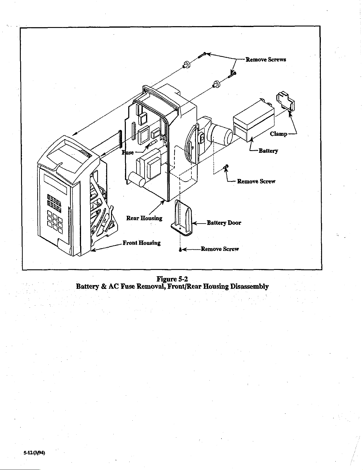
Battery & AC
Front
Fuse
Housing
Figure
Removal,
5-2
Front/Rear
Housing
Disassembly
512694
©

4.
Door
See
Figure
Open
door.
slide
door
and
remove
and
CPU
Separate
nect
wire
plate
switch.
To
remove
fasten
it
Assembly
5-3
for
the
following
Remove 2 screws
out.
Remove 2 screws
handle.
board.
front
assemblies
pressure
to
rear
Disconnect
Remove 4 screws
and
rear
from
plate
door
housing.
from lower
door
housings
pressure
assembly,
discussion.
hinge
from
door
latch/handle,
SPI cable
from
from
rear
door
slightly,
transducer
remove 4 screws
bracket
I/O
board
housing.
then
discon-
and
pressure
and
which
Reverse
cover
slides
the
process
into
the
for
front
reassembly,
pump
housing.
Membrane
being
Door
Switch
sure
the
ESD
Front
ESD
Cover
Remove
Screws
(4)
Door
Latch
(Handle)
Figure
Door
Disassembly
5-3
5133/94)
|
5.
CPU/Power
Assembly
Supply
Circuit
Board
assembly
bly
from
board
to
from
P102
pump
P103
on
I/O
on
I/O
board.
mechanism.
board,
and
sensor
Remove 4 screws
wire
assem-
fastening
DANGER
Unplug
bly
to
the
avoid
AC
risk
CAUTION
Handling
during
discharge
damage
CAUTIONBattery
be
disconnected
to
avoid
To
board,
Disconnect
threaded
nut,
and
From
filter
Slide
Reassemble
Before
tional
housing
of
the
disassembly;
(ESD)
could
circuit
remove
the
remove
SPI
Panel
and
internal
nut.
Remove 2 screws
inside
rear
wires
from
CPU/Power
in
replacing
and
accuracy
reassembly.
result.
CPU/Power
front
Lockout
reverse
power
cord
of
electric
printed
protection
must
be
connection
before
disassembling
damage.
housing
cable
from
Button
tooth
washer.
cover,
disconnect
CPU/Power
supply
order.
screws
in
check.
before
shock.
circuit
boards
provided
P104
supply,
first.
P200.
(turn
Remove
from
RS232
Supply
out
of
rear
pump
If
check
beginning
is
required
against
electrostatic
or
circuit
on 1/O
the
VO
Board,
On
rear
of
counter
audio
connector.
brown
and
board.
cover.
housing,
perform
is
satisfactory,
disassem-
board
board
must
circuit
or
pump,
boards
RS232
remove
clockwise),
volume
blue
knob
RFI
func-
complete
line
Reassemble
Before
functional
complete
7.
Membrane
in
replacing
and
housing
DANGER
Unplug AC
avoid
CAUTION
Handling
disassembly;
(ESD)
result.
risk
of
must
power
of
printed
be
CAUTION
Battery
nected
circuit
See
The
electronic
graphics.
removed
must
damage
connection
before
damage.
Figure
5-3
membrane
switch
Once
as a single
not
be
reinstalled
during
reverse
accuracy
order.
screws
in
pump
check.
reassembly.
Switch
cord
before
electric
protection
shock.
circuit
against
provided
P104
or
on
disassembling
for the
following
switch
consists
and
the
upper
in
place
on
the
unit.
The
after
removal
is
likely
housing,
If
check
perform
is
satisfactory,
Replacement
opening
boards
electrostatic
circuit
1/O
board must
the circuit
discussion.
of
two
overlay
door
original
removal
to
pump
is
required
board
damage
boards
parts;
with
assembly,
membrane
because
occur.
the
housing
during
discharge
could
be
discon-
to
avoid
the
lower
keypad
they
are
switch
electrical
to
6.
1/0
Board
:
DANGER
Unplug
avoid
AC
risk
CAUTION
-
Handling
disassembly;
(ESD)
must
result.
CAUTION
Battery
nected
circuit
The
(see
Disconnect
board
5-14
connection
before
damage.
I/O
board
Figure
and
(3/94)
Assembly
power
of
of
5-4).
SPI cable
P101
cord before
electric
printed
protection
be
provided
P104
disassembling
is
mounted
on
WO
shock.
circuit
boards
against
or
circuit
on
to
the
from
P200
board.
opening
is
required
electrostatic
board
I/O
board
must
the
circuit
back
of
the
on
CPU/Power
Disconnect
pump
discharge
damage
be
boards
pump
motor
housing
during
could
discon-
to
avoid
assembly
supply
wire
to
The
door
in
order
to
assembly
display
peel
residual
To
board,
up
and
adhesive
replace
below:
1.
Peel
release
(front
of
liner
on
2.
Thread
3.
Apply
around
vertically
tool
(see
pressure
4.
Once
electrical
release
from
back
must
be
disassembled
replace
is
opened,
then
discard
off
the
membrane
liner
membrane
front
must
ribbon
cable
membrane
outer
edges,
between
Section
on
domes
switch
liner
from
of
graphics
the
membrane
remove
remove
old
display
membrane
of
housing.
switch,
off
back
switch
not
be
removed
through
switch
to
around
rows
of
5.5
Special
themselves.
portion
its
front.
overlay.
(see step 4 Door
switch.
ribbon
connector
board.
switch.
follow
of
electronic
has
raised
domes).
at
this
slot
provided
door
front.
display
domed
Also,
windows,
switches
Tools).
is
firmly
remove
Avoid
Assembly)
Once
door
from
P403
On
front
of
Clean
any
the
instructions
switch
portion
Release
time.
on
door
Press firmly
and
using
keypad
excess
in
place,
remove
release
liner
on
door,
front.
5.
Place
graphics
making
portion.
windows,
keypad
excessive
6.
Connect
Press
Reassemble
and
housing
8.
DANGER
Unplug
avoid
CAUTION
Handling
disassembly;
(ESD)
result.
sure
Press
and
tool (see
pressure
ribbon
board
door
accuracy
reassembly.
Pump
AC
risk
of
must
©
Assembly
power
of
printed
be
overlay
to
line
it
up
firmly
around
vertically
Section
on
cable
to
firmly
into
as
described
check.
If
check
cord
electric
.
protection
shock,
circuit
provided
over
electrical
correctly
outer
between
5.5
Special
keypads
P403
on
board
retainers.
in
is
satisfactory,
before
boards
against
or
circuit
switch
portion,
with
electrical
edges,
around
rows
of
numbers
Tools).
themselves.
back
step
4.
opening
is
electrostatic
board
Avoid
of
display
Perform
complete
pump
required
damage
switch
display
using
board.
functional
housing
during
discharge
to
could
CAUTION
Battery
nected
circuit
‘The
assembly.
removal
pump
The
the
1.
‘2.
Reverse
housing.
functional
complete
connection
before
damage.
pump
assembly
Separation
of
the
assembly
pump
assembly
following
Remove
retaining
pin.
linkage
Remove 4 screws
assembly
screw from
ring
Raise
assembly
out.
the
procedure
Before
and
housing
arm
P104
on
disassembling
consists
of
the
front
YO
board
are
(see
Section
is
separated
manner:
linkage
from
connecting
of
the
drop-in
can
be
removed
from
cassette
to
reassemble
replacing
accuracy
reassembly.
screws
check.
I/O
board
the
circuit
of
the
cam
and
rear
required
5.9,
steps
from
the
assembly
link,
guide
from
housing
pump
in
housing,
If
check
must
be
discon-
boards
housing/motor
housings
prior
3'and
rear
and
remove
(see
frame
is
to
to
removing
6).
housing
upper
link
Figure
5.4)
assembly.
and
lift
pump
assembly
perform
satisfactory,
avoid
and
in
from
so
to
the
the
rear
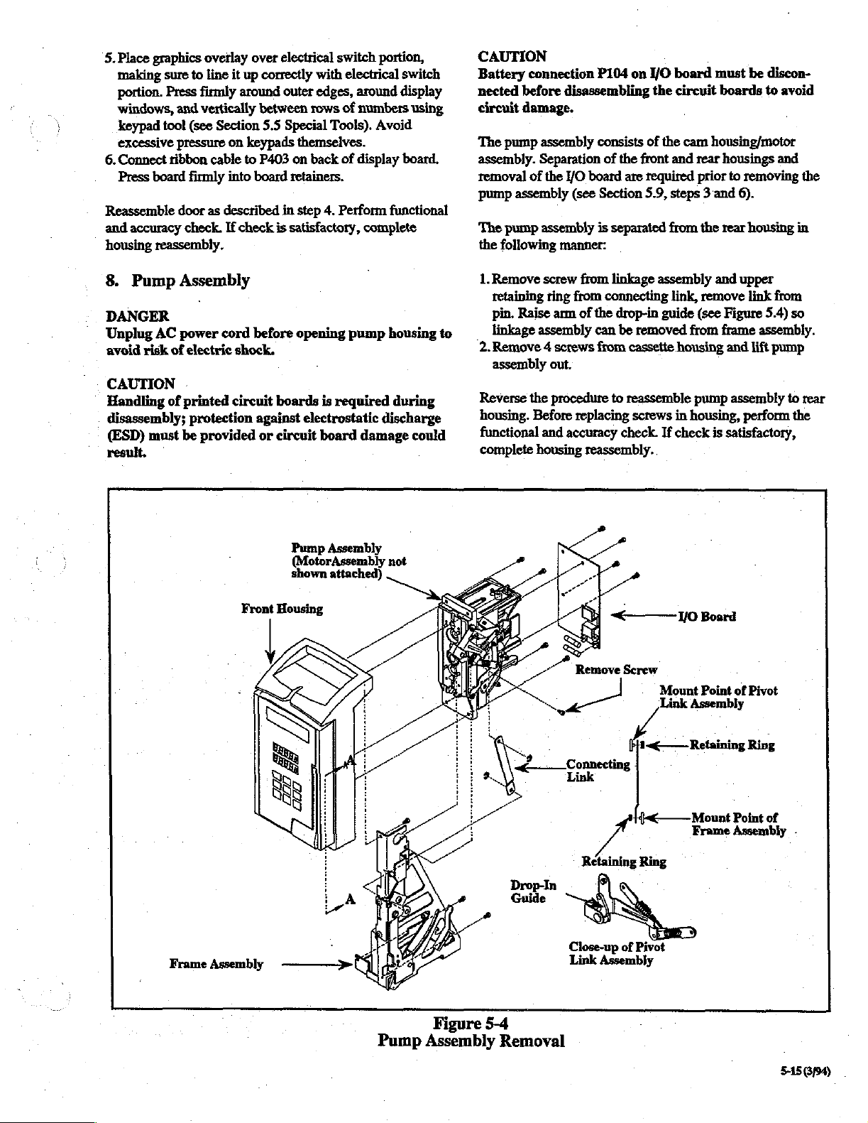
Pump
Assembly
Front
(MotorAssembly
shown
attached)
Housing
not
Remove
,
Connecting
Connectin;
Screw
Mount
Point
Link
Assembly
< — Retaining
of
Pivot
Ring
{<
^
Mount
Frame
Point
of
Assembly
.
Pump
Figure
Assembly
5-4
Removal
Close-up
Link
Assembly
of
Pivot
CEN
©
5150/94)
.

9.
Motor
Assembly
DANGER
Unplug
avoid
AC
risk
of
power
CAUTION
Handling
disassembly;
(ESD)
result.
CAUTION
Battery
nected
circuit
See
The
disassembied
Section
’
Remove 4 motor
out.
Remove
swing
of
must
connection
before
damage.
Figure
front
housing,
5.9,
Next,
remove
coupler
arm
printed
be
5-5
numbers
assembly
cord
before
electric
protection
disassembling
in
shock.
circuit
provided
P104
for
the
following
pump
order
to
3,
mounting
swing
gear.
Finally,
intact.
against
or
on
assembly,
remove
6,
and
screws
arm
opening
boards
circuit
I/O
damper
is
required
electrostatic
board
board
the
circuit
discussion.
and
the
motor
8).
and
take
from
remove
mounting
pump
damage
must
boards
I/O
board
assembly
motor
coupler
housing
during
discharge
could
be
discon-
to
avoid
must
be
(see
assembly
gear.
plate
with
to
Screw
Set
Coupler
yy,
A
;
Hub
i
i
(attached
cam
一
hteerfaee
一
人
я
>,
ring
Gap
Mounting
5-5
Gear
一
之 8 :
Figure
Motor
©
"<
i
Assembly
Coupler
shaft)
Here
Swing
to
end
of
Coupler
Damper
Arm
Platej
Arm
Reverse
NOTE
When
properly
the
sequence
assembling
align
CAUTION
Realignment
the
motor
and
inch
spacing
attached
which
coupler.
required
must
mounting
Reverse
all
cable
Reassemble
screws
check.
reassembly.
to
is
located
Repositioning
to
be
maintained
plate.
the
procedure
cables
and
clamps
in
housing,
If
check
the
achieve
the
to
reassemble.”
the
motor,
over
the
overpressure
of
the
motor
cam
shaft
is
required
cam
shaft
between
of
this
between
to
connectors
on
the
left
side
front
and
perform
is
satisfactory,
the
swing
coupler
have
between
and
the
the
spacing,
reassemble
and
of
rear
the
is
been
the
the
interface
motor
hub
coupler
Also a .125
the
coupler
secure
the
the
pump
housings.
functional
complete
arm
must
valve
shaft.
necessary
disassembled. A .002
hub
(sprocket)
the
pump.
SPI
housing.
Before
and
housing
whenever
coupler
coupler,
and
may
be
inch
gear
and
Reconnect
cable
with
replacing
accuracy
that
hub
gap
the
is
10.
Cassette
To
disassemble
board,
and
See
Figure
Remove
Slide
and
cassette
Reverse
11.
retaining
shaft
detector
housing.
the
Safety
DANGER
Unplug
avoid
AC
risk
CAUTION
Battery
nected
circuit
connection
before
damage.
Housing
the
cassette
pump
mechanism
5-6
for
the
following
ring
out
of
cassette
assemblies
procedure
Mechanism
Clip
power
cord
of
electric
shock.
P104
disassembling
housing,
from
one
housing.
from
to
assemble
before
on
the
must
be
removed
discussion.
end
of
Remove
cassette
`
I/O
the
housing
the
opening
board
circuit
front
housing,
first.
each
cassette
optical
and
cassette
pump
must
boards
housing.
be
I/O
shaft.
emitter
remove
housing
discon-
to
avoid
to
5-16(3/94)
See
Figure
The
front
cassette
clip
housing
mechanism.
5-6
for
the
housing,
must
following
pump
mechanism,
be
removed
discussion.
I/O
board,
to
disassemble
and
the
safety
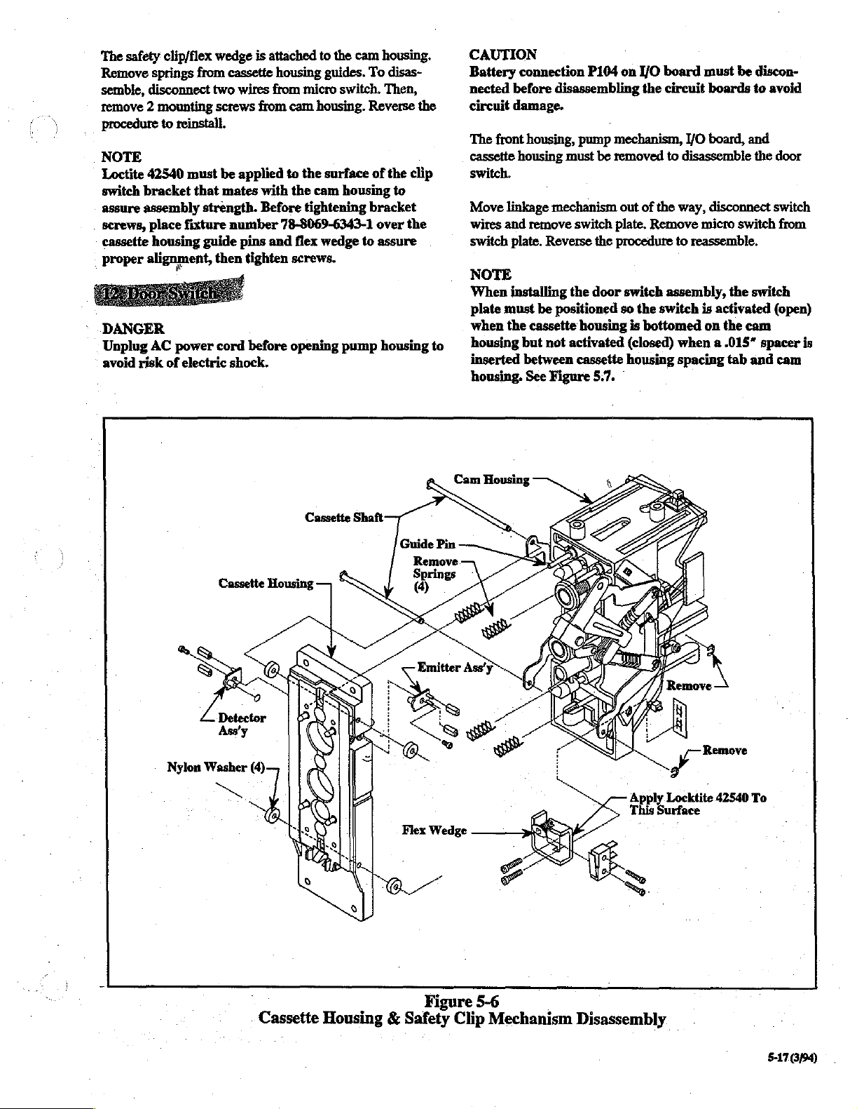
‘The
safety
clip/flex
Remove
semble,
remove 2 mounting
procedure
NOTE
Loctite
switch
assure
screws,
cassette
proper
DANGER
Unplug
avoid
springs
disconnect
to
reinstall.
42540
must
bracket
assembly
place
housing
alignment,
AC
risk
that
fixture
power
of
electric
from
strength.
guide
wedge
is
attached
cassette
two
screws
be
mates
number
then
cord before
shock.
housing
wires
from micro
from
applied
with
Before
pins
and
tighten
to
the
cam
guides.
cam
housing.
to
the
surface
the
cam
tightening
78-8069-6343-1
flex
wedge
screws.
opening
To
switch.
Reverse
of
housing
bracket
to
pump
housing.
disas-
Then,
the
the
clip
to
over
the
assure
housing
.
to
CAUTION
Battery
nected
circuit
The
cassette
switch.
Move
wires and
switch
NOTE
When
plate
when
housing
inserted
housing.
connection
before
damage.
front
housing
linkage
plate.
installing
must
the
disassembling
housing,
must
mechanism
remove
Reverse
the
be
positioned
cassette
but
not
activated
between
See
Figure
P104
on I/O
pump
mechanism,
be
removed
out
switch
plate.
the
procedure
door
switch
so
housing
cassette
5.7.
board
the
circuit
to
of
the
Remove
to
assembly,
the
switch
is
bottomed
(closed)
housing
when a .015"
spacing
must
be
boards
I/O
board,
disassemble
way,
disconnect
micro
switch
reassemble.
the
is
activated
on
the
cam
tab
discon-
to
avoid
and
the
door
switch
from
switch
(open)
spacer
and
cam
is
Cassette
Figure
Housing & Safety
5-6
Clip
Mechanism
yer
Apply
Locktite
This
Surface
Disassembly.
42540
To
511099

5.10
The
be
necessary
month
Calibration
also
CAUTION
The
should
ment
NOTE
3M
attend a Service
Infusion
service
Calibration
Checks
following
functional
be
Functional
of
Infusion
calibration
if
indicated
and
adjustment
performed
and
be
performed
any
of
the
Therapy
therapy
or
repair
and
following
following
Training
Service
of
this
and
adjustment
during
accuracy
of
affected
disassembly
Accuracy
following
components.
recommends
Seminar,
Center,
product.
and
the
check
Check
calibration
Voltage
procedures
recommended
(see
Section
components
arid
(see
that
technicians
offerred
prior
to
Insert
Two
Door
repair.
Section
and
beginning
Switch
may
twelve-
5.7).
must
5.7)
adjust-
by
the
015"
Points
Figure
3M
Spacer
(top & bottom)
Disassembly
Between
5-7
1.
Power
DANGER
Potentially
housing
To
avoid
severe
cord
DANGER
Unplug
avoid
NOTE
There
voltage
Diodes
logic
different
dangerous
is
opened
electric
injury
before
AC
risk
of
are
no
checks.
D9,
D10,
circuitry.
when
Supply
beginning
power
These
Voltage
and
shock
or
death,
cord
electric
required
and
Source
the
pump
shock.
D11
power
Check
voltages
the
with
always
disassembly
before
adjustments
is
are
AC
power
the
potential
unplug
opening
direct
voltage
to
the
operated
present
of
.
logic
on
cord
for
the
the
3M
pump
for
the
to
the
circuitry
battery
when
the
is
plugged
causing
AC
power
pumps.
housing
following
pump’s
is
than
when
in.
to
it
5-18(3/94)
is
operated
checks
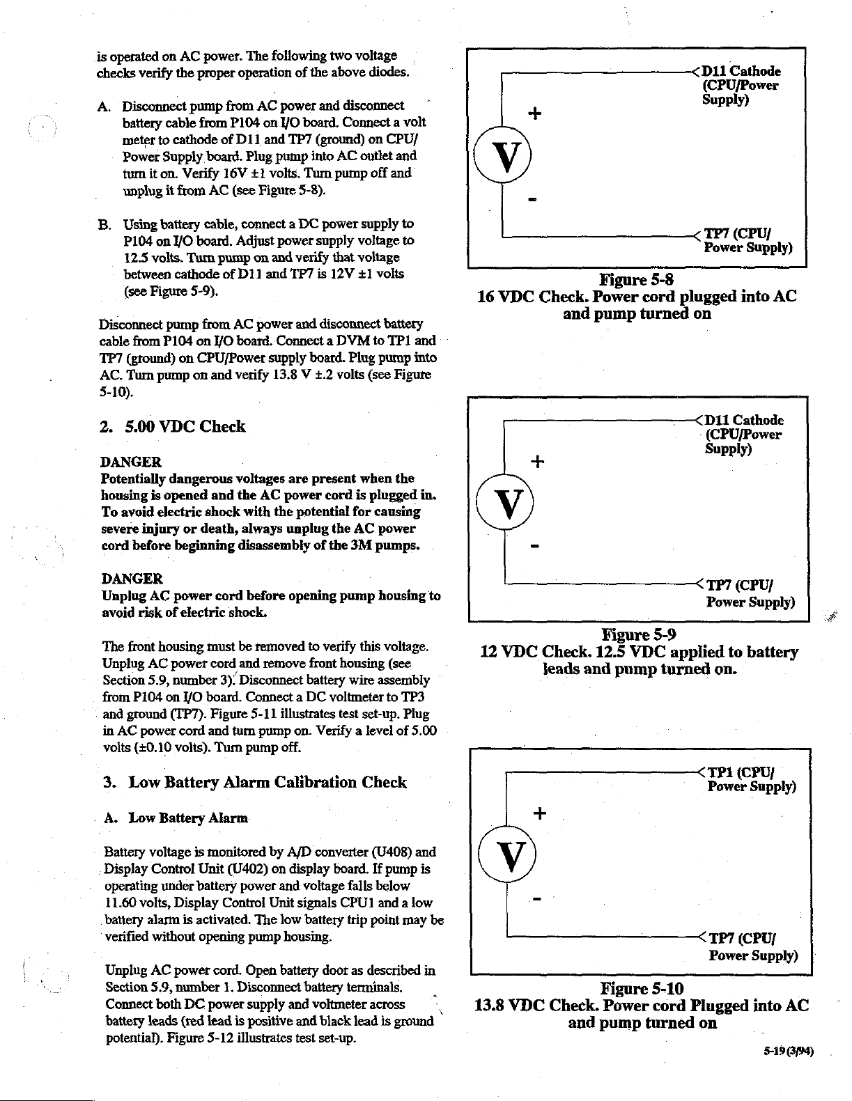
A.
B.
Disconnect
cable
TP7
AC.
5-10).
2.
DANGER
Potentially
housing
To
severe
cord
on
verify
‘Disconnect
battery
meter
Power
turn
unplug
Using
P104
between
avoid
cable
to
Supply
it
on.
it
battery
on
12.5
volts.
(see
Figure
pump
from
P104
(ground)
Turn
pump
5.00
VDC
is
opened
electric
injury
before
AC
power.
the
proper
pump
from
from
cathode
from
VO
cathode
board.
Verify
AC
cable,
board.
Turn
pump
5-9),
from
on
YO
on
CPU/Power
on
and
of
16V
of
Check
dangerous
and
shock
or
death,
beginning
The
following
operation
AC
power
P104
on
I/O
D11
and
TP7
Plug
pump
£1
volts.
(see
Figure
connect a DC
Adjust
power
on
and
D11
and
TP7
AC
power
board.
Connect a DVM
supply
verify
13.8 V +.2
・
voltages
the
with
always
disassembly
AC
are
power
the
unplug
two
of
the
above
and
disconnect
board.
Connect a volt
(ground)
into
AC
Turn
pump
5-8).
power
supply
verify
that
is
12V
and
disconnect
board.
Plug
volts
present
cord
potential
the
of
the
3M
voltage
diodes.
on
CPU/
outlet
off
and
supply
voltage
voltage
+1
volts
battery
to
TP1
pump
(see
Figure
when
is
plugged
for
causing
AC
power
pumps.
|,
and
to
to
the
and
into
in.
V
16
VDC
Check.
and
Figure
Power
pump
5-8
cord
plugged
turned
-
D1i
Cathode
(CPU/Power
Supply)
TP7
(CPU/
Power
Supply)
into
on
D11
Cathode
(CPU/Power
Supply)
AC
DANGER
Unplug
avoid
The
Unplug
Section
from
<
and
in
volts
3.
“A.
Battery
Display
operating
11.60
battery
verified
Unplug
Section
Connect
battery
potential).
risk
front
P104
ground
AC
power
(+0.10
Low
Low
volts,
AC
AC
5.9,
voltage
Control
alarm
without
AC
5.9,
leads
power
of
electric
housing
power
number
on
I/O
(TP7).
cord
volts).
Battery
Battery
is
Unit
under
battery
Display
is
activated.
opening
power
number
both
DC
(red
Figure
cord
before
shock.
must
be
removed
cord
and
remove
3):
Disconnect
board.
Connect a DC
Figure
5-11
and
tum
pump
Tum
pump
Alarm
Alarm
monitored
(402)
power
Control
The
pump
cord.
Open
1.
Disconnect
power
supply
lead
is
positive
5-12
illustrates
opening
illustrates
on.
off.
pump
to
verify
front
housing
battery
wire
voltmeter
test
Verify a level
Calibration
by
A/D
converter
on
display
and
Unit
low
housing.
battery
and
board.
voltage
signals
battery
door
battery
voltmeter
and
black
test
set-up.
falls
CPU1
trip
as
terminals.
housing
this
voltage.
(see
assembly
to
set-up.
of
Check
(U408)
If
pump
below
and a low
point
described
across
lead
is
ground
TP3
Plug
5.00
and
is
may
to
be
in
、
|
12
VDC
13.8
VDC
Check.
leads
+
Check.
and
Figure
12.5
and
Figure
Power
pump
VDC
pump
turned
5-9
applied
turned
5-10
cord
TP7
(CPU/
Power
to
on.
TP1
(CPU/
Power
ТРУ
(СРО!
Power
Plugged
on
Supply)
battery
Supply)
Supply)
into
AC
5-19
3/94)
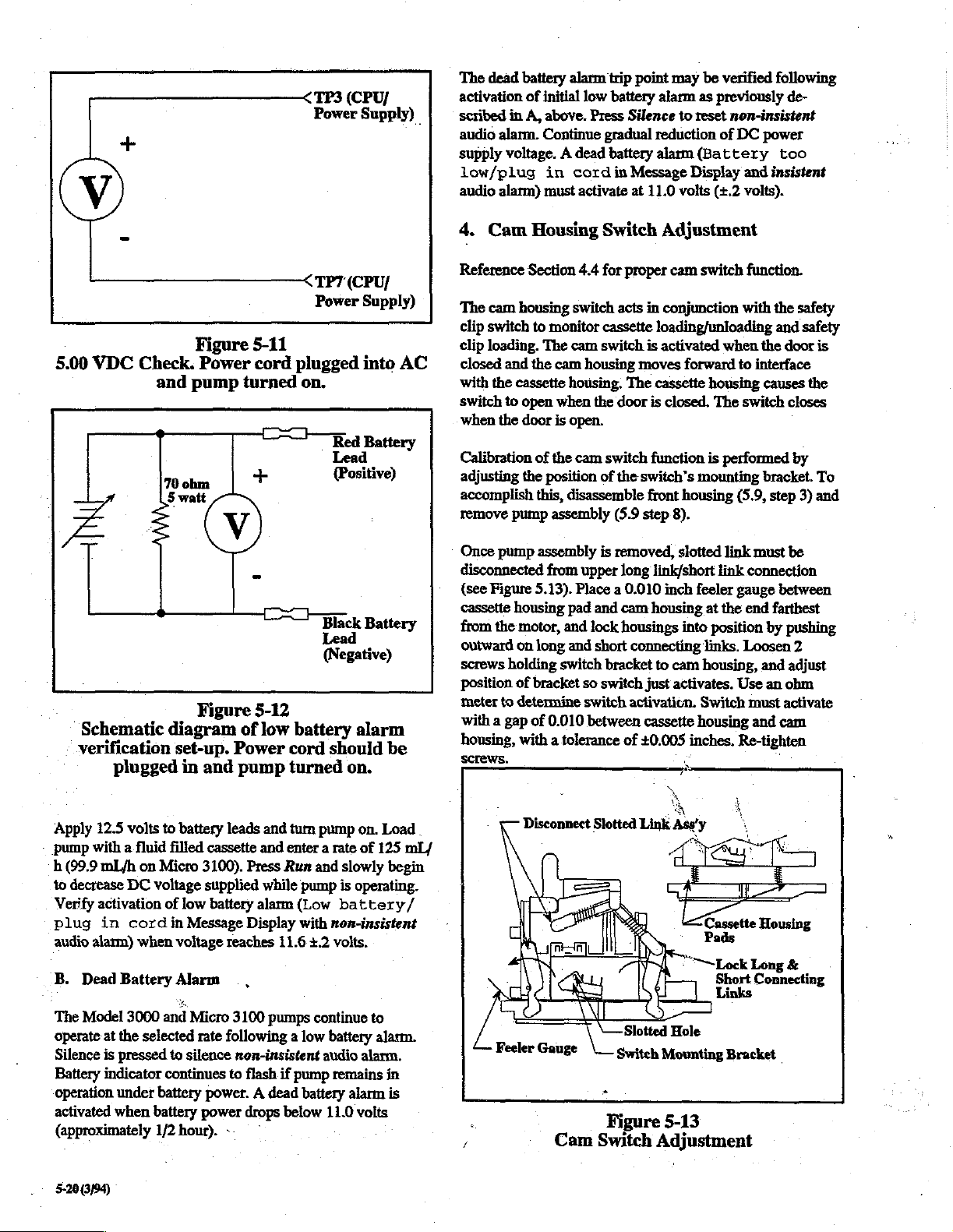
у
TP3
(CPU
Power
Supply)
The
dead
battery
activation
scribed
audio
supply
low/plug
audio
4.
of
in
A,
alarm.
voltage. A dead
alarm)
Cam
alarm
initial
low
above.
Press
Continue
in
cord
must
activate
Housing
trip
point
battery
Silence
gradual
battery
in
Message
at
11.0
Switch
may
be
verified
alarm
as
previously
to
reset
non-insistent
reduction
alarm
(Battery
Display
volts
(+.2
of
DC
Adjustment
following
de-
power
too
and
insistent
volts).
5.00
VDC
Schematic
verification
plugged
Check.
and
pump
diagram
set-up.
in
Figure
Power
turned
Figure
of
Power
and
pump
5-11
cord
5-12
low
TP7
Power
plugged
on.
Red
Lead
(Positive)
Black
Lead
(Negative)
battery
cord
should
turned
(CPU/
Supply)
into
Battery
Battery
alarm
on.
AC
be
Reference
The
clip
switch
clip
loading.
closed
with
switch
when
Calibration
adjusting
accomplish
remove
Once
disconnected
{see
cassette
from
outward
screws
position
meter
with a gap
housing,
Section
cam
housing
to
monitor
The
and
the
cam
the
cassette
to
open
when
the
door
is
of
the
the
position
this,
disassemble
pump
assembly
pump
assembly
from upper
Figure
5.13).
housing
the
motor,
and
on
long
holding
to
switch
of
bracket
determine
of
0.010
with a tolerance
4.4
for
proper
switch
acts
in
cassette
cam
switch
is
housing
housing.
open.
cam
Place a 0.010
pad
lock
and
so
switch
between
moves
The
the
door
switch
of
the
(5.9
is
removed,
long
and
cam
housings
short
connecting
bracket
switch
activation.
of
switch’s
step
just
cassette
+0.005
cam
switch
conjunction
loading/unloading
activated
forward
cassette
is
closed.
function
mounting
front
housing
8).
slotted
link/short
inch
feeler
housing
into
to
cam
activates.
Switch
housing
inches,
function.
with
when
to
interface
housing
The
switch
is
performed
(5.9,
link
must
link
connection
gauge
at
the
end
position
links.
Loosen
housing,
Use
must
and
Re-tighten
the
causes
bracket.
by
and
an
the
safety
and
safety
door
is
the
closes
by
To
step
3)
and
be
between
farthest
pushing
2
adjust
obm
activate
cam
Apply
12.5
volts
pump
with a fluid
h
(99.9
mL/h
on
to
decrease
Verify
plug
audio
B.
The
operate
Silence
Battery
operation
activated
(approximately
5-20
DC
activation
in
cord
alarm)
when
Dead
Battery
Model
3000
at
the
is
pressed
indicator
under
when
(3/94)
voltage
selected
battery
to
battery
filled
Micro
of
in
voltage reaches
Alarm
and
to
continues
battery
1/2
hour).
leads
cassette
3100).
supplied
low
battery
Message
|,
Micro
3100
rate
following a low
silence
non-insistent
to
power. A dead
power
--
and
turn
and
enter a rate
Press
Run
while
alarm
Display
11.6
pumps
flash
if
drops
below
|
pump
and
slowly
pump
is
(Low
battery/
with
non-insistent
+.2
volts.
continue
battery
audio
pump
remains
battery
alarm
11.0
on.
Load.
of
125
mL/
begin
operating.
to
alarm.
alarm.
jn
is
volts
Disconnect
Feeler
.
/
Gauge
Cam
Slotted
Link
ρα
©
Slotted
Switch
Mounting
Figure
Switch
5-13
Adjustment
Asy'y
*
“Lock
Short
Links
Hole
Long
8
Connecting
Bracket
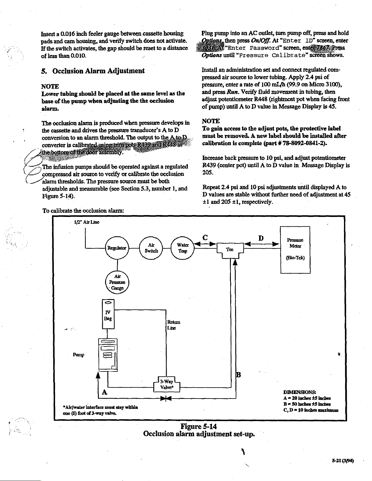
Insert a 0.016
pads
and
cam
If
the
switch
of
less
than 0.010.
5.
Occlusion
NOTE
Lower
base
alarm.
tubing
of
the
pump
inch
feeler
housing,
activates,
should
and
the
Alarm
be
when
gauge
between
verify
switch
gap
should
Adjustment
placed
adjusting
at
the
the the
cassette
does
be
reset
っ
same
occlusion
housing
not
activate.
to a distance
level
as
the
Plug
pump
Options
Install
pressed
pressure,
and
press
adjust
of
pump)
into
an
AC
outlet,
then
press
On/Off.
“Enter
until
an
administration
air
source
enter a rate
Run.
potentiometer
until A to D value
Password”
“Pressure
to
lower
of
Verify
fluid
R448
turn
At“Enter
screen,
Calibrate”
set
and
connect
tubing.
100
mL/h
movement
(rightmost
in
Message
pump
Apply
(99.9
in
pot
off,
press
ID”
screen,
en
screen
regulated
2.4
psi
of
on
Micro
tubing,
when
Display
then
facing
is
and
hold
enter
shows.
com-
3100),
front
45.
The
occlusion
the
cassette
conversion
の
Ls
he
infusion
impressed
im
adjustable
Figure
To
calibrate
alarm
and
drives
to
an
pumps
air
source
thresholds.
and
measurable
5-14).
the
>
1/2”
Pump
4
*Air}water
foot
(1)
one
is
produced
the
alarm
threshold.
should
to
verify
The
pressure
occlusion
Air
Line
>
Iv
Bag
[=>
E
E
A
A
©
interface
of
3-way
must
valve.
when
pressure
(see
alarm:
transducer’s A to
The
be
operated
or
calibrate
source
Section
|
E
within
stay
pressure
output
against a regulated
must
5.3,
develops
to
the
the
occlusion
be
both
number
D
A
1,
Line
:
3Way
Valve*
pré
Occlusion
in
and
Figure
alarm
NOTE
To
gain
access
must
be
removed. A new
calibration
Increase
R439
205.
Repeat
D
+1
back
(center
2.4
values
and
205
psi
are
5-14
adjustment
to
the
adjust
is
complete
pressute
pot)
and
stabie
+1,
to
until A to D value
10
psi
without
respectively.
B
set-up.
pots, the
label
(part # 78-8092-0841-2).
10
psi,
adjustments
further
protective
should
and
be
adjust
in
Message
until
need
of
Pressure
Meter
(Bio-Tek)
installed
potentiometer
displayed A to
adjustment
DIMENSIONS:
inches
20
=
A
B=
50
inches
2
10
=
C,D
+5
£5
inches
inches
inches
maximum
label
Display
e
after
is
at
45
>
À
=.
5-21
3/94)

6.
Empty
NOTE
Before
top
solution,
The
spring
piston
is
the
during
The
The
-
calibrating
piston
moves
etc.
empty
bag
contact.
as
its
mounted
wire
depressions
pronounced
the
minor
only
major
Calibration
require
5.9,
accomplished
the
cam
switch.
to
contact
each
cam
which
perimeter
depression.
when
the
depression.
and
that
the
number
housing
Bag
Contacts
the
empty
freely
contacts
The
wire
drive
(metering)
the
cam
housing.
briefly
touches
revolution
of
(see
and
upper
front
3).
by
of
drives
the
the
metering
Figure
is
called
The
piston
adjustment
housing
Calibration
turning
just
above
Adjustment
bag
and
is
consist
contact
cam
the
cam
upper
cam
5-15).
One
the
major
empty
shaft
of
the
be
of
the
the
dog
and
contact,
not
impeded
of a rigid
moves
tums.
Its
position
the
spring
shaft
piston
is
depression
depression.
bag
is
in
empty
disassembled
empty
point
to
the
verify
wire
with
The
is
contact
(see
Figure
is
the
designed
contacts
contact
bag
bag
set
screw
rear
of
that
by
dried
contact
the
spring
calibrated
metering
with
is
must
with
contacts
(see
contacts
the
upper
contact
once
4-3).
two
more
The
other
touch
the
Section
located
cam.
and
cam.
is
the
a
so
is
on
Calibrate
©
Turn
and
e
Connect
and
e
Manually
Upper
held
metering
@
Adjust
perform
Empty
filled,
of
level
(the
handle).
flow
these
for
clockwise.
Hf
lower
inches
flow
mL.
position
pump
connector
pin 6 of
piston
inward
dog
bag
non-checkvalve
999
mL/h
in
the
top
of
The
above
conditions,
less
sensitivity
the
pump
the
above
above
of
spring
off
and
partially
P102
an
ohmmeter
connector
rotate
cam
is
spring
so
that
cam
during
point
set
as
specified
calibration
(99.9
mL/h
bag
at 6
5/8
the
pump
is
pump
should
pump”
the
empty
by
runs
for 6 mL
solution
top
pump”
level
of
Micro
contact
on
I/O
board.
between
P102
shaft
while
loaded
its
shaft
maintains
rotation.
screw
until
on
Figure
should
be
set
and
on
Micro
inches
defined
run
alarm.
bag
tuming
the
under
to 2 5/8
3100).
alarm
as
follows:
disconnect
TP8
(pin L is
to
5.15.
tested
operating
wire
(ground
at
observing
out
position.
contact
empty
bag
by
the
3100),
above
the
top
as
the
flat
area
for 6 mL
If
contact
inches
before
without a “No
an
alarm
should
dogpoint
the
above
above
You
should
the
pump
assembly
potential)
top).
ohmmeter.
It
must
be
with
contacts
installing a fluid
pump
at a rate
with
the
fluid
of
the
pump
below
the
occurs
under
be
adjusted
set
screw
conditions,
the
pump
(3/8
get a “No
infuses
3
Empty
when
bag
upper
A=
contacts
piston
shaft
Major
Depression
MUST
touch
is
here.
Metering
Cam
Figure
Related
as
Empty
when
5-15
Empty
to
bag
contacts
upper
B = Minor
Contacts
Bag
piston
MUST
shaft
is
here.
Depression
NOT
touch
yi
-
5-22
(494)
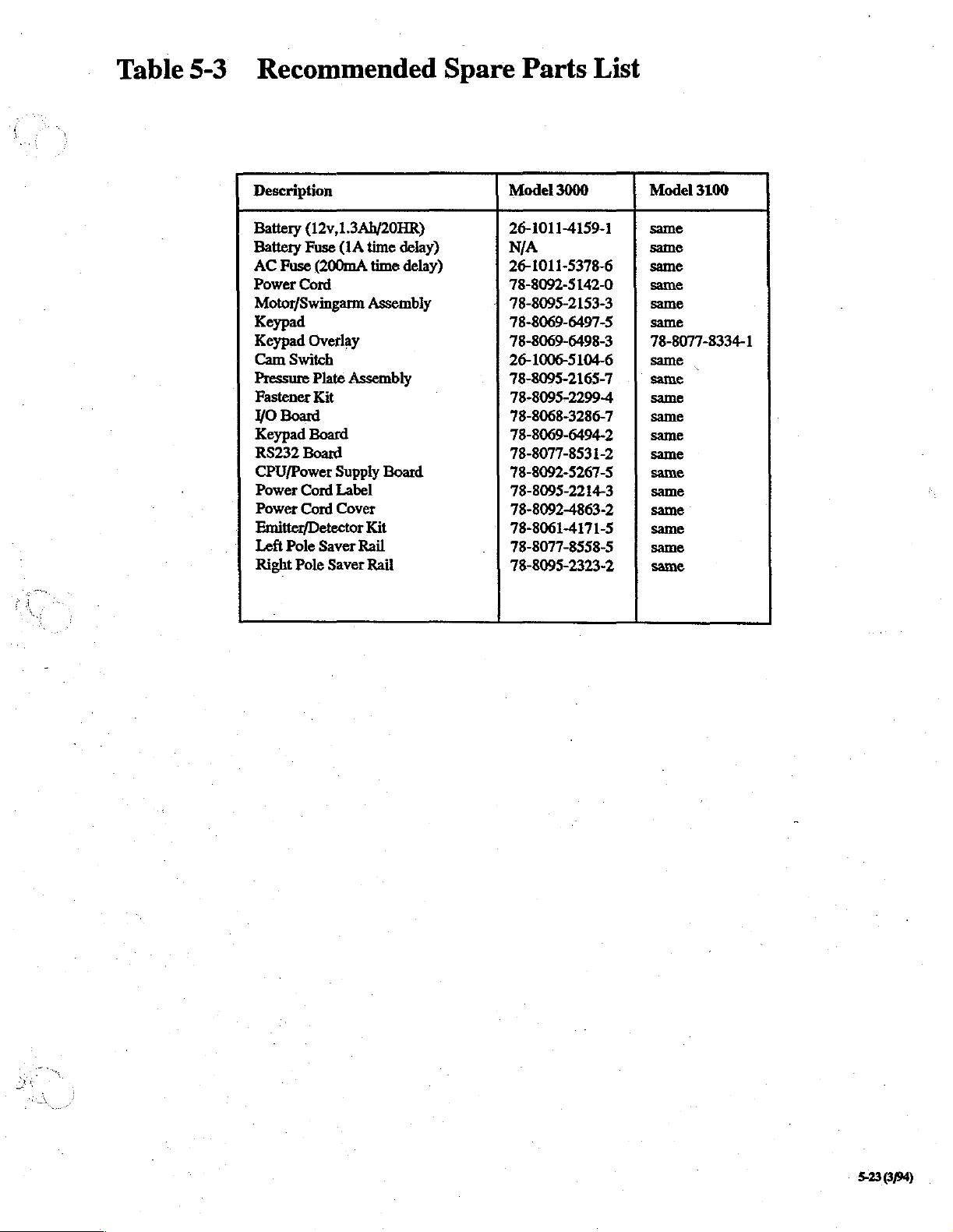
Table
5-3
Recommended
Description
Battery
Battery
AC
Power
Motor/Swingarm
Keypad
Keypad
Cam
Pressure
Fastener
YO
Keypad
RS232
CPU/Power
Power
Power
Emitter/Detector
Left
Right
(12v,1.3Ah/20HR)
Fuse
(1A
Fuse
(200mA
Cord
Overlay
Switch
Plate
Assembiy
Kit
Board
Board
Board
Supply
Cord
Label
Cord
Cover
Pole
Saver
Rail
Pole
Saver
time delay)
time
delay)
Assembly
Board
Kit
Rail
Spare
Model
26-1011-4159-1
N/A
26-1011-5378-6
78-8092-5142-0
78-8095-2153-3
78-8069-6497-5
78-8069-6498-3
26-1006-5104-6
78-8095-2165-7
78-8095-2299-4
78-8068-3286-7
78-8069-6494-2
78-8077-8531-2
78-8092-5267-5
78-8095-2214-3
78-8092-4863-2
78-8061-4171-5
78-8077-8558-5
78-8095-2323-2
Parts
3000
List
Model
3100
same
same
same
same
same
same
78-8077-8334-1
same
|
same
same
same
same
same
same
same
same
same
same
same
5-23
8/94)

This
Page
Intentionally
Left
Blank
5-24(3/94)

Section
6:
Parts
Lists
and
Diagrams
Model
3000
and
Micro
3100
6.1
The
structural
Volumetric
are
(see
NOTE
Pump
may
and any
mailed
products.
CAUTION
Because
Micro
mount
recommended.
Mechanical
following
parts
Infusion
available
Section
be
from
5.1).
specifications
changed
instructions
to
you
the
3100
Infusion
technology,
tables
of
the
Pumps.
3M
without
as
required
circuit
boards
component
and
and
figures
3M
Model
Current
Infusion
and
parts
notice.
required
for
used
Pumps
Structural
identify
3000
Therapy
of
for
proper
are
level
mechanical
and
parts
Customer
the
3M
Updated
this
manual
service
in
the
Model
primarily
repair
Parts
Micro
3100
aid
price
infusion
tables,
will
of
these
3000
surface
is
not
and
lists
Service
pumps
figures,
be
and
61604

Table
o
6-1
Reference
From
Figure
2
3
4
5
7
15
24
33
Designation
6-1
1
6
8
9
10
il
12
13
14
16
17
18
19
20
21
2
23
25
26
27
28
29
30
31
32
34
Pump
Description
Cassette
Cassette
Emitter/Detector
Clip
Cassette
E-Ring
Modified
Link - Short
Ribbon
Cable
Tapered
Double
Valve/Piston
Empty
Assembly
Housing
Washer - Nylon
Guide
Shaft
(1/8")
Link - Long
Cable
Clamp
Cam
Back
Foam
Cam
Housing
Coil
Flat
Washer
C-Ring
(1/16)
Spring
Bag
Contact
Empty
Bag
Contact
Bearing
Spacer
Molded
Special
YO
Switch
Snap Switch
Pivot
Switch
Spring
Flat
Modified
Shaft/Molded
Empty
Optical
Flange
Ring
Cam
#10
Board
Wiring
Plate
Link
Assembly
Bracket
Valve
Assembly
Shaft/Molded
Bag
Filter
Assembly
Flat
Spring
Assembly
Assembly
Guide
Shaft
Tape
Spring
Washer
Harness
Clip
Piston
Assembly
Piston
Parts
Model
3000
78-8092-4839-2
26-1011-4189-8
78-8061-4171-5———
78-8077-8384-6
78-8077-8284-8
NA
78-8092-4970-5
78-8077-8278-0
N/A N/A
N/A
78-8077-8274-9
78-8005-3202-6
78-8077-8275-6
78-8061-4232-5
N/A
N/A
78-8637-2811-6
78-8061-4230-9
78-8061-4225-9
78-8077-8347-3
78-8079-5879-4
‘78-8079-5989-1
78-8079-6410-7
78-8092-0789-3
78-8095-2289-5
26-1006-5104-6
78-8092-4995-2
78-8095-2212-7
78-8003-8346-1
78-8092-4945-7
78-8092-4855-8
78-8079-6005-5
78-8061-4288-7
78-8079-5958-6
Micro
3100
same
same
|-
same
same
same
N/A
same
same
N/A
same
same
same
same
N/A
N/A
same
same
same
same
same
same
same
same
same
same
same
same
same
same
same
зате
same
same
6-2
м.
(394)
 Loading...