

Page 1
3M
™
Water Filtration Products
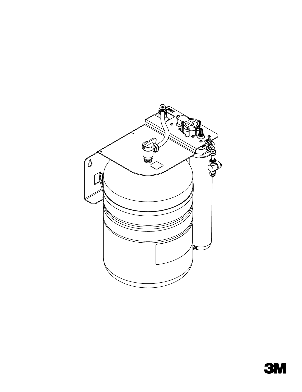
FlashGARD HP
Model Number FSTMO75
™
Reverse Osmosis Filtration System
Part Number 56123-06
Installer: Please leave this manual with owner/operator.
End User: Please retain for operation and future maintenance instructions.
1
Page 2
3M™Water Filtration Products
SAFETY INFORMATION
Read, understand, and follow all safety information contained in these instructions prior to installation and use of the Reverse Osmosis Water
Treatment System. Retain these instructions for future reference.
Intended use: The FlashGARD-HP FSTMO75 Water Treatment System is intended for use in filtering potable water for food service coffee, espresso and
steamer equipment and has not been evaluated for other uses. The system is typically installed near where filtered drinking water is desired, and must be
installed as specified in the installation instructions. The system is intended for indoor installations and must be installed by qualified professional installer
according to these installation instructions.
EXPLANATION OF SIGNAL WORD CONSEQUENCES
WARNING
CAUTION
CAUTION
Indicates a potentially hazardous situation, which, if not avoided, could result in death or serious injury and/or property damage.
Indicates a potentially hazardous situation which, if not avoided, may result in minor or moderate injury and/or property
damage.
Indicates a potentially hazardous situation, which, if not avoided, may result in property damage.
WARNING
To reduce the risk associated with choking:
• Do not allow children under 3 years of age to have access to small parts during the installation of this product.
To reduce the risk associated with hazardous voltage due to an installer drilling through existing electric wiring or water pipes in the area
of installation:
• Do not install near electric wiring or piping which may be in path of a drilling tool when selecting the position to mount the filter bracket.
To reduce the risk of physical injury:
• Depressurize system as shown in manual prior to cartridge removal.
To reduce the risk associated with back strain:
• Follow safe lifting procedures.
CAUTION
To reduce the risk associated with property damage due to water leakage:
• Read and follow Use Instructions before installation and use of this system.
• Before starting installation, shut off main water supply and drain pipes.
• Installation and Use MUST comply with all state and local plumbing codes.
•Protect from freezing, remove cartridge when temperatures are expected to drop below 40° F (4.4° C);
•Do not install on hot water supply lines. The maximum operating water temperature of this filter system is 100°F (37.8°C).
•Do not install if water pressure exceeds 100 psi (690 kPa). If your water pressure exceeds 80 psi (552 kPa) you must
install a pressure limiting valve. Contact a plumbing professional if you are uncertain how to check your water pressure.
• Do not install where water hammer conditions may occur. If water hammer conditions exist, you must install a water hammer
arrester. Contact a plumbing professional if you are uncertain how to check for this condition.
• Do not use a torch or other high temperature sources near filter system, cartridges, plastic fittings or plastic plumbing.
• Do not install unit if collet is missing. Contact your Sales Representative if collets are missing from any fittings.
• On plastic fittings, never use pipe sealant or pipe dope. Use PTFE thread tape only, pipe dope properties may deteriorate plastic.
• Take care when using pliers or pipe wrenches to tighten plastic fittings, as damage may occur if overtightening occurs.
•Do not install in direct sunlight or outdoors.
•Do not install near water pipes which will be in path of a drilling tool when selecting the position to mount the bracket.
• Mount filter in such a position as to prevent it from being struck by other items used in the area of installation.
• Ensure that the location and fasteners will support the weight of the system when installed.
• Ensure all tubing and fittings are secure and free of leaks.
• The disposable filter cartridge MUST be replaced every 12 months or at the rated capacity or if a noticeable reduction in flow rate occurs.
IMPORTANT NOTES
• Failure to follow instructions may void warranty.
• Allow a minimum of 1.5” (3.8 cm) clear space under filter to facilitate cartridge change.
• Install with the inlet and outlet ports as labeled. Make sure not to reverse connections.
• Some local codes may require the use of a licensed plumber or certified installer when disrupting a potable water line.
2
Page 3
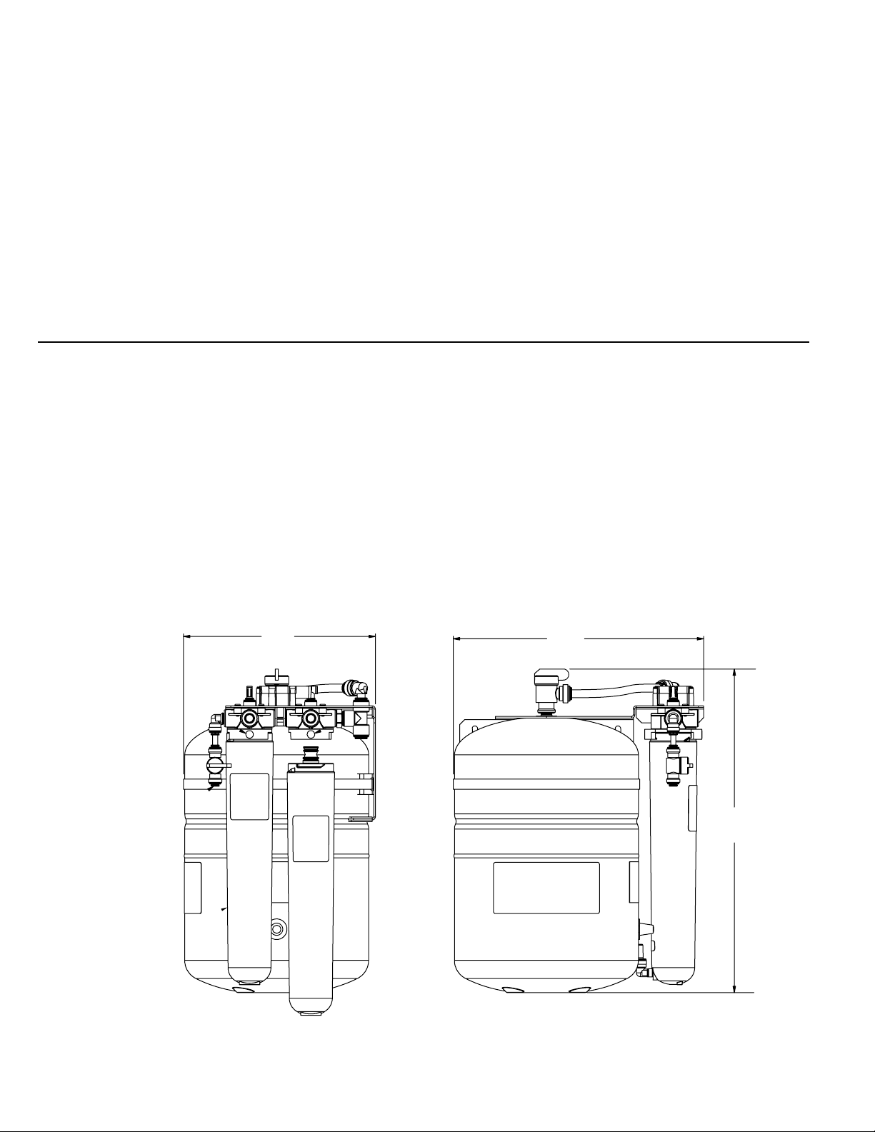
Table of Contents
Safety Instructions ................................................................................................................................................................ Page 2
Caution and Warning Statements............................................................................................................................................ Page 2
Parts List............................................................................................................................................................................... Page 3
Product Dimensions .............................................................................................................................................................. Page 3
Mounting............................................................................................................................................................................... Page 4
Plumbing Connections .......................................................................................................................................................... Page 5
System Start-Up.................................................................................................................................................................... Page 6
Cartridge Change Instructions ............................................................................................................................................... Page 6-7
Product Replacement Parts ................................................................................................................................................... Page 7
Tank Pressure Checking ........................................................................................................................................................ Page 7
Troubleshooting Guide .......................................................................................................................................................... Page 8
Mounting Template ............................................................................................................................................................... Page 9
Warranty .............................................................................................................................................................................. Page 12
Parts List
The following parts are included with the FlashGARD-HP FSTMO75 Reverse Osmosis Water Filtration System. Please unpack the con-
tents from the product box and check to verify that all of the Parts listed below are included. Should any parts be missing, please
CUNO at 1-800-800-0657.
contact
Qty Description
1 Tank & Bracket Assembly
1 Pre-filter Cartridge
1 Reverse Osmosis Membrane Cartridge
1 Water Sample Valve Assembly (includes 3/8” Reducing Tee, 1/4” Shut-off Valve and Blue Tubing)
1 12 ” (30.5 cm) of length of 3/8” blue tubing
1 10’ (305 cm) length of 1/4” of red tubing
Product Dimensions
9 3/8"
(23.8 cm)
12 1/4"
(31.1 cm)
15 7/8"
(40.3 cm)
Figure 1
3
Page 4

Mounting
To reduce the risk associated with property damage due to water leakage:
• Before starting installation, shut off main water supply and drain pipes.
• Take care when using pliers or pipe wrenches to tighten plastic fittings, as damage may occur if overtightening occurs.
• Do not install in direct sunlight or outdoors.
•Do not install near water pipes which will be in path of a drilling tool when selecting the position to mount the bracket.
• Mount filter in such a position as to prevent it from being struck by other items used in the area of installation.
• Ensure that the location and fasteners will support the weight of the system when installed.
1) Remove the mounting bracket template (see page10) from thismanual. Tape it to the wall where the mounting bracket is to be installed.
2) Install mounting screws (not included) into each of the keyhole locations on the template. Be sure to leave a 1/8” to 1/4” space
between the bottom of the screw head and the wall so that the bracket can be hung.
CAUTION: Mounting hardware and mounting location must be capable of supporting a minimum of 30lbs (13.6 kg).
3) Hang the Bracket/Tank Assembly from the mounting screws.
4) Once the bracket is hung, tighten the mounting screws so that the bracket is snug between the screw and the wall.
CAUTION
4
Page 5

Plumbing Connections
CAUTION : The FlashGard-HP Reverse Osmosis Water Filtration System requires a minimum 60 psi (413.7 kPa) inlet water pres-
sure. To ensure adequate inlet water pressure, it is recommended that the system be plumbed after the beverage booster pump
but before the beverage water filtration system. Refer to Figure 2 for proper tubing connections.
CAUTION: Use care in routing the tubing to ensure that there are no bends or kinks.
CAUTION
To reduce the risk associated with property damage due to water leakage:
• Before starting installation, shut off main water supply and drain pipes.
• Installation and Use MUST comply with all state and local plumbing codes.
•Do not install on hot water supply lines. The maximum operating water temperature of this filter system is 100°F (37.8°C).
•Do not install if water pressure exceeds 100 psi (690 kPa). If your water pressure exceeds 80 psi (552 kPa) you must
a pressure limiting valve. Contact a plumbing professional if you are uncertain how to check your water pressure.
install
•Do not install where water hammer conditions may occur. If water hammer conditions exist, you must install a water hammer
arrester. Contact a plumbing professional if you are uncertain how to check for this condition.
• Do not use a torch or other high temperature sources near filter system, cartridges, plastic fittings or plastic plumbing.
• Do not install unit if collet is missing. Contact your Sales Representative if collets are missing from any fittings.
• On plastic fittings, never use pipe sealant or pipe dope. Use PTFE thread tape only, pipe dope properties may deteriorate plastic.
• Take care when using pliers or pipe wrenches to tighten plastic fittings, as damage may occur if overtightening occurs.
•Do not install in direct sunlight or outdoors.
• Ensure all tubing and fittings are secure and free of leaks.
1) Shut off water supply and/or beverage water booster pump.
2) Route the water supply or booster pump to the RO system’s inlet water valve.
3) Assemble the water sample valve assembly (Refer to Figure 2A).
a.
b.
c.
Push small piece of tubing into tee.
Push opposite end of the small piece of tubing into 1/4” ball valve.
Push remaining section of the blue tube into the other end of the ball valve.
4) Cut a piece of the 3/8” blue tubing (included). Connect one end to the outlet tee on the RO system and the other end to one side
of the Water Sample Valve Assembly (See Figure 2).
5) Run length of tubing from the other end of the Water Sample Valve Assembly to the inlet of the steamer. See Figure 2.
Inlet Water Valve
1/4 x1/4
Stem x Barb Adapter
Feedwater from
Beverage Booster
System
Prefilter Cartridge
P/N 55706-08
SFC Tubing
1/4” Red Tubing
(To Drain)
Tank Shut-Off Valve
3/8” Reducing Tee
3/8” Blue Tubing
Water Sample
Valve Assembly
(See Figure 2A)
Reverse Osmosis (RO) Membrane
P/N 55987-15
Schrader Air Valve
To Steamer
Small Piece of 1/4” Blue Tubing
1/4” Ball Valve
Remaining Piece of Tubing
Figure 2 Figure 2A
5
Page 6

Using Push-In Fittings
To Attach Tubing
Push tubing in as far as it will go. Tubing must be inserted past
o-ring and hit backstop. Pull tube to ensure it is secured.
1 1
2
To Release Tubing
Push in grey collet to release tubing. With collet held,
pull tubing straight out.
2
CAUTION
To reduce the risk associated with property damage due to water leakage:
• Ensure all tubing and fittings are secure and free of leaks.
• Do not install unit if collet is missing. Contact 3M if collets are missing from any fittings.
Figure 3
System Start-Up
1) Remove the prefilter cartridge from its packaging. Remove the red cap from the cartridge and moisten the o-rings with water Insert the
cartridge interconnect into the filter head. Be sure that the ears on the cartridge line up with the spaces in the head. Then, turn the cart-
ridge 1/4 turn to the right.
NOTE: Be sure to install the cartridges into the proper heads by matching the icons on the cartridge labels with the icon on the heads.
2) Repeat Step 1 for the RO Membrane.
3) Remove the plug from the RO cartridge and attach the SFC tubing (red tube included with the included with the cartridge). See Figure 4.
Connect 1/4”red tube to the SFC connector. Run the red tube to the drain. CAUTION: DO NOT CUT THE RED SFC TUBE. It controls the
flow of water to drain.
4) Check that all plumbing connections are secure.
5) Open tank shut-off valve and inlet water valve. Turn on the beverage booster pump and check the system for leaks. If any leaks are
noted, turn off the water supply and/or booster pump and correct the leak before proceeding. If a leak is detected at a push-in fit-
ting, refer to Figure 3.
6) Divert the Water Sample Valve outlet to drain.Open valve and let water run through the RO system to drain for 10 minutes.
7) Close valve. NOTE: Please allow the water tank to fill (approximately 60 minutes) before using steamer.
Pre-filter Cartridge & RO Membrane Cartridge Change-out Instructions
Pre-filter Cartridge (Replace every 12 months)
1)
Close
tank shut-off and inlet valves (see Figure 2).
2)
Depressurize system.
Turn used prefilter cartridge 1/4 turn to the left. 3)
Pull down on cartridge. 4)
Discard used cartridge.5)
Remove red cap from new cartridge and moisten the o-ring with water. 6)
of new cartridge into the filter head. Be sure that
Insert
the ears on
the cartridge line up with the spaces in the head.
Turn new cartridge 1/4 turn to the right. 7)
Open tank shut-off and inlet valves (see Figure 2). 8)
Check for leaks.
9)
NOTE: Be sure to install the cartridge into the proper head by matching
the icon on the cartridge label with the icon on the head.
10) Divert the Water Sample Valve outlet to drain.Open valve and let water
run through the RO system to drain for 10 minutes.
11) Close valve. NOTE: Please allow the water tank to fill (approximately
60 minutes) before using steamer.
Figure 4
RO Membrane Cartridge (Replace every 24-36 months)
1) Close tank shut-off and inlet valves (see Figure 2).
2)
Depressurize system.
3)
Turn used
RO membrane cartridge
1/4 turn to the left.
6
Page 7

7
Tools Required:
• Piece of 1/4” tubing or Bucket
• Bicycle or tire pressure gauge
• Bicycle tire pump
1) Empty the storage tank.
a. Shut off the inlet water valve and Water Booster System if applicable.
b. Make sure tank shut-off valve located at the top of the water tank is open.
c. Attach a piece of tubing from the water sample valve to drain OR use a bucket to catch water from the water sample valve.
d. Open the water sample valve and drain the tank until empty. Leave water sample valve open.
2) Unscrew the blue cap on the side of the tank to expose the Schrader Air Valve.
3)
4)
Read the tank's air pressure using a standard bicycle or automobile tire pressure gauge that is capable of reading pressure
accurately from 0-10 psi (0 - 68.9 kPa).
5)
The air pressure should be between 8 -10psi (55.2 - 68.9 kPa).
6)
If the air pressure is below 8 psi (55.2 kPa) or above 10 psi (68.9 kPa) complete the following steps.
a. Using a standard bicycle pump add or release air pressure in the tank.
b. Repeat Steps 4-5 until the pressure is 8-10 psi (55.2 - 68.9 kPa).
c. Make sure the blue cap is put back onto the air pressure port.
7)
Close the water sample valve.
8)
Open the tank shut-off valve. Turn on the inlet water valve and booster pump if they were turned off.
Allow 60 minutes for tank to fill before operating the steamer.
To reduce the risk associated with property damage due to water leakage:
• Tank Pressure should be checked yearly.
CAUTION
Tank Pressure Check
Part Number Description
54-3030 Stainless Steel bracket complete with filter heads and RO shut-off valve
56-161351 Tank
60-23298 Tank shut-off valve
30-6049 Tank banding clamp
55706-08 Pre-filter cartridge-Must be replaced every twelve months or at the specified service cycle.
55987-15 RO module-Must be replaced every 24-36 months or at the specified service cycle.
60-232270 Inlet water valve
82-11302 3/8" blue tubing -1 ft (30.5 m)
82-11205 1/4" red tubing - 10 ft (3.05 m)
52-318203 2 3/4” Stealth flow control tube assembly
68512-03 Water Sample Valve Assembly (Includes 3/8” Reducing Tee, tubing and 1/4”Shut-off Valve)
74-3560404 1/4” x 1/4” Stem x Barb Adapter
74-3560604 3/8” x 1/4” Stem x Barb Adapter
Replacement Parts
RO Membrane Cartridge (Replace every 24-36 months) continued
Pull down on RO cartridge. 4)
Discard used RO cartridge. 5)
Remove red cap from new RO cartridge and moisten the o-ring with water. 6)
Insert new RO cartridge into the filter head. Be sure that the ears on the cartridge line up with the spaces in the head. 7)
Turn new cartridge 1/4 turn to the right. 8)
9)
Open tank shut-off and inlet valves (see Figure 2)
10) Divert the Water Sample Valve outlet to drain.Open valve and let water run through the RO system to drain for 10 minutes.
11) Close valve. NOTE: Please allow the water tank to fill (approximately 60 minutes) before using steamer.
Page 8

Troubleshooting Guide
Problem Cause Solution
Repair Beverage Booster
Low Feed Water Pressure
RO Membrane Fouled
Unit Runs Low or
Out of Water
Storage Tank Air Charge
is Low
Pre-Filter is Plugged by
Sediment (Particles)
Slow Leak in the Distribu
tion Line
RO Membrane Partially
Fouled, Unit can not produce enough water to
keep up the demand
Pump/System
Add Booster Pump
Replace RO Module and SFC
Tubing (Stealth Flow Control)
Drain Tank using Sample Valve,
with Sample Valve Open, Pumpup Air Charge, 8 -10 psi (55.2
- 68.9 kPa), close Sample Valve
Replace Pre-Filter
Repair Leak
Replace RO Module and SFC
Tubing (Stealth Flow Control)
Assembly
Notes
Contact Dealer
Only if Beverage Booster System is
not installed
Feed Water Pressure, Temperature,
RO Module Flow Rate and Reject
Water should be checked
Unscrew Blue Cap to access Schrader
Air Valve
A more frequent Pre-Filter change-out
schedule may be needed
The unit produces filtered water
slowly. A dripping leak can prevent
the tank from filling
High levels of hardness minerals may
be present in feed water, monitor
reject flow for plugging
Unit Never Shuts Off
(Continually Runs to
Drain)
Product Water Check
Valve has failed allowing
storage tank flow to drain
after unit is shut off
Hydraulic Shut-off Valve
has failed
Check Reject Water flow to drain
in the morning. Unit should be
off and no flow to drain. If flow
to drain exists, turn off the feed
water valve and check for flow to
drain on 10 minutes. If the flow
to drain remains steady, replace
RO Module
Replace valve
Reject Water flow to drain should stop
when the feed water valve is off
Should only be performed by a quali
fied technician
-
8
Page 9

91011
Page 10

Page 11

Page 12

Warranty and Limited Remedy:
THE FOLLOWING WARRANTIES ARE MADE IN LIEU OF ALL OTHER WARRANTIES, EXPRESS OR IMPLIED, INCLUDING, BUT NOT LIMITED TO, ANY IMPLIED WARRANTY OF MERCHANTABILITY,
THE IMPLIED WARRANTY OF FITNESS FOR A PARTICULAR PURPOSE AND ANY IMPLIED WARRANTY ARISING OUT OF A COURSE OF DEALING, A CUSTOM OR USAGE OF TRADE:
CUNO Incorporated warrants this Product to be free from defects in material and workmanship to the original end-user when installed in accordance with the Installation and Use Guide accompanying
the product. The warranty period commences from the date of installation and is as follows:
For a period of 2 YEARS - The entire system
If any part is proved to be defective within the noted warranty period, the exclusive remedy and CUNO’s sole obligation shall be to repair or replace the part, provided the defective part is returned
immediately to the factory or authorized repair dealers designated by CUNO. CUNO shall have no obligation to provide or pay for the labor required to install the repaired or replacement part in the
filtration system. This warranty does not cover failures resulting from abuse, alteration, or damage not caused by CUNO or failure to follow installation and use instructions. If the Product is defective
CUNO will replace the Product.
Limitation of Liability: Except where prohibited by law, CUNO will not be liable for any direct, indirect, special, incidental, or consequential damages arising from the use of this Product. To obtain
warranty service, mail your request to Warranty Claims, CUNO Incorporated, 400 Research Parkway, Meriden, CT 06450. Proof of purchase (original sales receipt) must accompany the warranty claim,
along with a complete description of the Product, model number and alleged defect.
a 3M company
CUNO Incorporated
400 Research Parkway
Meriden, CT 0645 0, USA
Toll Free: 1.888.218.CUNO
© 2008 3M Company. All rights reserved.
3M and CUNO are trademarks of 3M Company used under license.
INSTR4226 DRAFT
12
Worldwide: 20 3.2 37.5541
Fax: 203.238.8701
www.cunofoodservice.com
-
 Loading...