

Page 1

Dual T1/PRI
Network Application Card
Product Reference
Part No. 1.024.1367- 01
Version Number 3.1
Page 2

Dual T1/PRI
®
Network Application Card
Product Reference
Version 3.1
http://www.3com.com/
Part No. 1.024.1367-01
Page 3

3Com Corporation
5400 Bayfront Plaza
Santa Clara, California
95052-8145
Copyright © 1999, 3Com Corporation. All rights reserved. No part of this documentation may be reproduced
in any form or by any means or used to make any derivative work (such as translation, transformation, or
adaptation) without written permission from 3Com Corporation.
3Com Corporation reserves the right to revise this documentation and to make changes in content from time
to time without obligation on the part of 3Com Corporation to provide notification of such revision or change.
3Com Corporation provides this documentation without warranty of any kind, either implied or expressed,
including, but not limited to, the implied warranties of merchantability and fitness for a particular purpose.
3Com may make improvements or changes in the product(s) and/or the program(s) described in this
documentation at any time.
UNITED STATES GOVERNMENT LEGENDS:
If you are a United States government agency, then this documentation and the software described herein are
provided to you subject to the following:
United States Government Legend:
developed solely at private expense. Software is delivered as Commercial Computer Software as defined in
DFARS 252.227-7014 (June 1995) or as a commercial item as defined in FAR 2.101(a) and as such is provided
with only such rights as are provided in 3Com’s standard commercial license for the Software. Technical data is
provided with limited rights only as provided in DFAR 252.227-7015 (Nov 1995) or FAR 52.227-14
(June 1987), whichever is applicable. You agree not to remove or deface any portion of any legend provided
on any licensed program or documentation contained in, or delivered to you in conjunction with, this
User Guide.
Unless otherwise indicated, 3Com registered trademarks are registered in the United States and may or may
not be registered in other countries.
3Com and the 3Com logo are registered trademarks of 3Com Corporation.
Other brand and product names may be registered trademarks or trademarks of their respective holders.
YEAR 2000 INFORMATION:
For information on Year 2000 compliance and 3Com products, visit the 3Com Year 2000 web page:
http://www.3Com.com/products/yr2000.html
All technical data and computer software is commercial in nature and
Page 4

ONTENTS
C
A
BOUT THIS REFERENCE
Finding Specific Information in This Reference ........................................i
Conventions..........................................................................................ii
Contacting 3Com..................................................................................ii
O
1
2
VERVIEW
Supported Features ...........................................................................1-1
Accessing the User Interface.............................................................. 1-1
D
T1/PRI C
UAL
Configuring Span Lines 1 and 2......................................................... 2-1
Menu Option 1 ............................................................................ 2-2
Configuring the span line’s framing mode............................... 2-2
Menu Option 2 ............................................................................ 2-2
Configuring the span line’s line coding....................................2-2
Menu Option 3 ............................................................................ 2-2
Responding to a span line remote (framer) loopback............... 2-2
Menu Option 4 ............................................................................ 2-3
Configuring the span line’s jitter attenuation........................... 2-3
Menu Option 5 ............................................................................ 2-3
Configuring the span line’s transmit line build out................... 2-3
Menu Option 6 ............................................................................ 2-4
Configuring for the Telco’s switch type.................................... 2-4
Menu Option 7 ............................................................................ 2-4
Configuring the span line’s idle bit pattern.............................. 2-4
Menu Option 8 ............................................................................ 2-5
Mapping the span line’s DS0s to chassis modems.................... 2-5
Menu Option 9 ............................................................................ 2-6
Configuring the span line’s signaling channel..........................2-6
ONFIGURATION
i
Page 5

Menu Option 10...........................................................................2-6
Configuring the span line’s interface ID....................................2-6
Menu Option 11...........................................................................2-6
Configuring span level call-type blocking.................................2-6
Menu Option 12...........................................................................2-6
Configuring span level cause codes .........................................2-6
Menu Option 13...........................................................................2-7
Configuring the DS0 level call-type blocking............................2-7
Menu Option 14...........................................................................2-8
Configuring the DS0 level service state....................................2-8
Menu Option 15...........................................................................2-8
Configuring the Short Haul NIC line length..............................2-8
Menu Option 16...........................................................................2-9
Allowing for ALERTING message in response to SETUP request 2-9
Configuring Inbound Call Routing....................................................2-10
Menu Option 1...........................................................................2-10
Selecting a Gateway to process digital calls............................2-10
Menu Option 2...........................................................................2-10
Allowing modem analog calls................................................2-10
Menu Option 3...........................................................................2-11
Configuring inbound call routing...........................................2-11
Menu Options 4 and 5................................................................2-11
Checking the inbound call routing configuration status .........2-11
Menu Option 6...........................................................................2-12
Mapping inbound phone numbers to reserved pools .............2-12
Menu Option 7...........................................................................2-13
Mapping chassis modem channels to reserved pools..............2-13
Menu Option 8...........................................................................2-13
Mapping digital reserved pools to chassis Gateways ..............2-13
Menu Option 9...........................................................................2-14
Allowing ISDN-GWC termination...........................................2-14
Configuring the Card.......................................................................2-14
Menu Option 1...........................................................................2-14
Saving configuration changes to NVRAM...............................2-14
Menu Option 2...........................................................................2-15
Restoring configuration from NVRAM....................................2-15
Menu Option 3...........................................................................2-15
Restoring the default configuration .......................................2-15
ii
Page 6

Menu Option 4 .......................................................................... 2-15
Assigning timing source priority ............................................ 2-15
Menu Option 5 .......................................................................... 2-15
Configuring chassis slot devices ............................................ 2-15
Menu Option 6 .......................................................................... 2-16
Configuring the modem routing method .............................. 2-16
Menu Option 7 .......................................................................... 2-16
Configuring the UI console password.................................... 2-16
Menu Option 8 .......................................................................... 2-16
Enabling automatic DS0 state change ................................... 2-16
Menu Option 9 .......................................................................... 2-17
Companding Code Configuration......................................... 2-17
Configuring Software Fault Event Logging....................................... 2-17
D
3
T1/PRI M
UAL
Dual T1/PRI Commands..................................................................... 3-1
Menu Option 1 ............................................................................ 3-2
Resetting the highest priority timing source.............................3-2
Menu Option 2 ............................................................................ 3-2
Resetting the PRI NAC.............................................................3-2
Menu Option 3 ............................................................................ 3-2
Enter/Exit span-to-span pass-thru loopback mode ................... 3-2
Menu Options 4 and 6.................................................................3-3
Forcing receiver reframe on the span lines............................... 3-3
Menu Options 5 and 7.................................................................3-3
Disconnecting calls on specific span line B-channels ................ 3-3
Menu Option 8 ............................................................................ 3-3
Forcing the NAC to master the TDM bus.................................3-3
Menu Options 9 and 10...............................................................3-3
Entering and exiting locally initiated loopbacks on the
span lines ....... ...... ....... ...... ....... ...................................... ....... .. 3-3
Menu Option 11 .......................................................................... 3-4
Disabling red ALARM LEDs...................................................... 3-4
Menu Options 12 and 13 .............................................................3-4
Connect/disconnect B-channel on span lines 1 and 2 .............. 3-4
Menu Options 14 and 15 .............................................................3-4
Changing individual DS0 service states.................................... 3-4
AINTENANCE
iii
Page 7

Menu Options 16 and 17..............................................................3-4
Changing span line service state..............................................3-4
Logging Out of the UI Console...........................................................3-5
D
4
T1/PRI S
UAL
Dual T1/PRI Status Displays.................................................................4-1
Menu Option 1.............................................................................4-2
Checking power-up self test status ..........................................4-2
Menu Option 2.............................................................................4-3
Checking the T1/PRI’s overall status .........................................4-3
Menu Option 3.............................................................................4-3
Checking chassis slot device configurations .............................4-3
Menu Option 4.............................................................................4-4
Checking DS0/modem channel status......................................4-4
Menu Option 5.............................................................................4-4
Checking the chassis’ ISDN gateway status..............................4-4
Menu Options 6 and 8..................................................................4-5
Checking span line 1 and 2’s DS0 status..................................4-5
Menu Options 7 and 9..................................................................4-6
Checking span line 1 and 2’s alarm/event status ......................4-6
TATUS DISPLAYS
T
A
iv
ROUBLE CLEARING
Using the LEDs.................................................................................. A-1
About T1/PRI Alarm Levels ........................................................... A-2
Correcting Alarm/Error Conditions ............................................... A-3
Using SNMP Traps............................................................................. A-4
T
B
ECHNICAL SPECIFICATIONS
Certification.......................................................................................B-1
Regulatory Compliance Statements...............................................B-1
United States...........................................................................B-1
FCC Part 15 Compliance Statement.........................................B-1
Current Draw.....................................................................................B-1
Page 8

Environment...................................................................................... B-2
Shipping and Storage................................................................... B-2
Operating .................................................................................... B-2
Physical Dimensions........................................................................... B-2
v
Page 9

BOUT
A
About This Reference provides an overview of this reference, tells where
to look for specific information and how to contact 3Com, and lists
document conventions.
This reference describes how to configure the Dual T1/PRI via its user
interface (UI) console.
This reference is intended for a networ k engineer or a network
technician. It is assumed that the user of this documentation will possess
a working knowledge of LAN and WAN technologies.
If the information in the release notes shipped with your product differs
from the information in this reference, follow the instructions in the
release notes.
T
HIS
EFERENCE
R
Finding Specific Information in This Reference
This table shows the location of specific information in this reference.
If you are looking for Turn to
A List of Supported Features Chapter 1
Configuration Information Chapter 2
Maintenance Information Chapter 3
Status Displays Chapter 4
Page 10

ii
BOUT THIS REFERENCE
A
Conventions
Contacting 3Com
This table lists conventions use d throughout this reference.
Icon Notice Type Description
Information note Information that contains important features or
instructions.
Caution Information to alert you to potential damage to a
program, system, or device.
Warning Information to alert you to potential personal injury
or fatality. May also alert you to potential electrical
hazard.
ESD Information to alert you to take proper grounding
precautions before handling a product.
Call the appropriate number listed below for technical support.
■
If you are calling from the United States or Canada
Dial 1.800.231.8770
■
If you are calling from Europe, Middle East, or Africa
Dial +353.1.823.7700 (+ represents your international carrier code
and 353 represents the Ireland country code, where 3Com
International Customer Services is located)
■
If you are calling from all other locations
Dial (your international carrier code) 847.797.6600
Refer to the Total Control Hub Documentation CD-ROM for more
information regarding product warranty.
For information about Customer Service, including support, training,
code releases and updates, contracts, and documentation , visit our
website at
http://totalservice.usr.com
Page 11

1
VERVIEW
O
This chapter contains an overview of supported features and instructions
for accessing the Dual T1/PRI Network Application Card (NAC) through
the user interfac e ( UI) co ns o le .
Supported Features
Accessing the User Interface
These features are supported in this release:
■
RFC-1406 (Definitions of Managed Objects for the DS1 and E1
Interface Types) Error Counters—UAS, CCS, and SEFS
■
Increased Number of Modem Pools—from 4 to 12
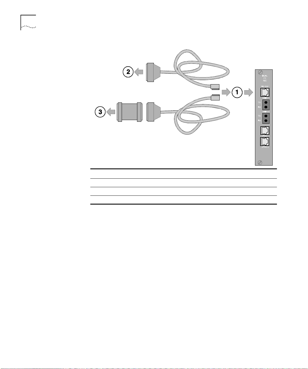
To access the Dual T1/PRI NAC’s UI console, connect the following cables
to the corresponding Network Interface Card (NIC) RS-232 port.
This port’s baud rate is defined by DIP switch settings on the Dual T1/PRI
NAC. Refer to the NAC’s Getting Started Guide for more information.
Page 12
1-2
HAPTER
C
1: O
VERVIEW
Callout # Description
1 RJ-45 connector to NIC’s RS-232 port
2 DB-25 male connector to modem for remote operations
3 DB-25 female-to-female null modem adapter to PC or terminal
Page 13

2
UAL
D
This chapter provides configuration information for span lines 1 and 2,
inbound call routing, software fault event logging, and the card.
T1/PRI C
ONFIGURATION
Configuring Span Lines 1 and 2
Configure span lines 1 and 2 by selecting options 5 and 6 from the user
interface (UI) console’s main menu.
Copyright | 3Com Corporation, 1998
Dual T1/PRI Application Card Revision 3.1.4 (Card Id: 27)
Boot Code Linked Date : Mon Dec 04 17:41:48 1995
Operation Code Linked Date: Tue Feb 23 16:41:51 1999
Main Menu
1 Command
2 Status
3 Card Configuration
4 Inbound Call Routing Configuration
5 Span Line 1 Conf iguration
6 Span Line 2 Conf iguration
7 SW Fault Manager Event Logging
8 Logout
Enter menu selection and press Return.
Menu Selection (1-8):
Page 14

2-2
HAPTER
C
2: D
UAL
T1/PRI C
ONFIGURATION
The UI console menu options for configuring both spans are identical.
Selecting options 5 or 6 from the main menu produces this scree n for
that span:
Span Line 1 Configuration Current Setting
1 Framing Mode ESF
2 Line Coding B8ZS
3 Remote Loopback Ignore
4 Jitter Attenuation Transmitter
5 Transmit Line Build Out 0.0 fN
6 Switch Type (Boot time) Config=5ESS(AT&T)Act.=5ESS (AT&T)
7 Idle Byte Sent to TELCO FE Hex
8 DSO to Modem Slot/Chan Mapping
9 Signaling Channel Config (Boot time) Config=D-channel Act.=D-channel
10 Interface ID 0
11 Span Level Call Type Blocking No Call Blocked
12 Span Level Cause Codes
13 DS0 Level Ca ll Type Blocking
14 DS0 Level S ervice State
15 Short Haul NIC Line Length Not Applicable
16 Use ALERTING Response NO
(NOTE: Changing configur ation parameters may affect calls in progress.)
Enter menu selection and press Retur n or press Esc to exit.
Menu Selection (1-16):
Menu Option 1 Configuring the span line’s framing mode
The framing mode selects th e T 1 format.
Menu Option 2 Configuring the span line’s line coding
Line coding dictates how the data stream is encoded on the span line.
Menu Option 3 Responding to a span line remote (framer) loopback
Performing a framer lo opback is one method of performing enhanced
trouble clearing. The NAC is put in a “waiting” state for the Telco’s
loopback (loop-up/loop-down) signal if con figured to respond. Various
network nodes can be put into loopback in order to isolate “trouble
spots” in the network.
Page 15

Configuring Span Lines 1 and 2
This diagram represents this process.
Encoded HDB3 Signal
Bit Stream
Framer Circuitry
Line Interface Unit
Transformer
Configure the NAC framer to r e spond or ignore the loop-up/loop-down
pattern from the Telco.
Menu Option 4 Configuring the span line’s jitter attenuation
Jitter attenuation on the span lin e en ha n ces the ne two rk in te rfa ce card
(NIC) tolerance to jitter. The NIC’s hardware provides a 193-bit frame
buffer to compensate for low frequency jitter on the network .
2-3
This option allows you to attenuate jitter on the receiving (from switch to
you) and the transmitting (from you to switch) sides. It defaults to the
attenuate jitter on the transmi ttin g side .
If you are using the Dual Channelized T1 (386) NAC with a Short Haul
(DSX-1) NIC, jitter attenuation is only allowed on the receiving side.
Menu Option 5 Configuring the span line’s transmit line build out
The span line’s transmit line b uild out is a config urable output at tenuation
that can be set to satisfy T1 circuit requirements.
Page 16

2-4
HAPTER
C
2: D
UAL
T1/PRI C
ONFIGURATION
There are four attenuation values to choose from:
■
0.0 dB (default)
■
7.5 dB
■
15.0 dB
■
22.5 dB
Menu Option 6 Configuring for the Telco’s switch type
In order to receive or place calls to the Telco on the span line, configure
the NAC to work with the type of switch the Telco is using.
The following switch types are supported:
■
4ESS (AT&T)
■
5ESS (AT&T)
■
DMS 100 (Northern Telecom)
■
INS-1500 (NTT)
■
NI2
Menu option 6 di spla ys a
configured
and an
actual
value represents any configuration changes made, and the actual val ue
represents the switch type the card is currently configured for.
Configuration chan ges will not take effect until card is rebooted.
Once you reboot , the confi gur e d an d actu al v alues remain the same until
additional changes are made.
Menu Option 7 Configuring the span line’s idle bit pattern
The span line’s idle bit pattern is an 8-bi t pattern placed on any channel
not carrying a call.
This pattern is usually dictated by the Telco and is configured at the NIC
by entering a 2-digit hexadecimal number at the prompt. The default is
FE Hex.
value. The confi gured
Page 17

Configuring Span Lines 1 and 2
Menu Option 8 Mapping the span line’s DS0s to chassis modems
The Total Control chassis contains 17 NAC slots. Two typical chassis
configurations are:
■
Configuration 1
■
Slot 1: T1/PRI Card
■
Slots 2–16: Quad Modem or Quad I-modem Cards
■
Slot 17: Network Man a gement Card
■
Configuration 2
■
Slot 1: T1/PRI Card
■
Slots 2–15: Quad Modem/Quad I-modem Cards
■
Slot 16: NETServer or NETServer PRI Card
■
Slot 17: Network Man a gement Card
Each of the slots populated by a Quad Modem Card contains four
modem channels numbered sequentially 1–4 from top to bottom.
2-5
This option allows you to map span line time slots to these modem
channels.
Use the following syntax when configuring this option:
DS0#:sl#/ch#
Where:
DS0#
= DS0 number (1–23)
sl#
= Chassis modem slot number (1–16)
ch#
= Chassis modem channel number (1–4)
When a modem is moved to a DS0, the DS 0 it was associated with prior
to the move becomes unmapped.
Page 18

2-6
HAPTER
C
2: D
UAL
T1/PRI C
ONFIGURATION
Menu Option 9 Configuring the span line’s signaling channel
If using non-facility associated signaling ( NFAS), configure a B- or
D-channel for signaling purposes.
Menu Option 10 Configuring the span line’s interface ID
If using NFAS, configure the interface ID specified by the Telco with this
option.
The default is 0 for non-NFAS.
Menu Option 11 Configuring span level call-type blocking
Span level call-type blocking allows specific types of calls to be rejected
when placed on the span.
Configure the call-type blocking featu re for one of these:
■
All calls (analog and digital) blocked
■
Analog calls blocked
■
Digital calls blocked
■
No calls blocked
Any changes made will take affect on the next call.
Menu Option 12 Configuring span level cause codes
When calls are rejected at the span level, configure a cause code to be
transmitted to the Telco.
Page 19

Configuring Span Lines 1 and 2
The following types of cause codes are supported:
Cause Code Type Default Cause Code Value Description
A 58 All calls blocked
B 58 Analog calls blocked
C 58 Digital calls blocked
D 58 No modems available
E 58 No gateway available
Use the following syntax when configuring this option:
CCT:CCV
Where:
CCT
= Cause code type
CCV
= Cause code value (0–127)
R
Pressing
at the prompt resets all codes to the default value of 58.
2-7
Configuration changes will take place immediately.
Menu Option 1 3 Configur ing the DS0 leve l call-type blocking
DS0 level call-type blocking allows specific types of incoming calls to be
rejected when pl aced on the channel or DS0.
Configure the call-type bloc k in g feat ure for:
■
All calls (analog and digital) blocked
■
Analog calls blocked
■
Digital calls blocked
■
No calls blocked
Any changes made will take effect on the next call.
Use the following syntax when configuring this option:
BCT:DS0#
BCT:DS0#,DS0#,DS#-DS#,...
(to configure a single DS0)
(to configure multiple DS0s or a
range of DS0s)
Page 20

2-8
HAPTER
C
2: D
UAL
T1/PRI C
ONFIGURATION
Where:
BCT
= blocked call type (A for analog calls, N for none, D for
digital, B for both analog and digital.)
DS0#
= DS0 number, 1–23 (24 is reserved as the D-channel)
The blocked call-type column has two subheadings: configured and
current.
As changes are made to this screen, the configured and current column
are updated to reflect the ne w configuration.
If DS0 call-type blocking commands were issued to the T1/PRI through
Total Contro l Mana ge r soft ware or som e oth er MIB brow ser, the current
column displays the call-type being blocked by the command.
Menu Option 14 Configuring the DS0 level service state
This option allows you to remove or restore a DS0 from/to service.
The ability to selectively route calls on specific B-channels are useful for
debugging.
Use the following syntax when configuring this option:
DSS: DS0#
DSS: DS0#, DS0#, DS0#-DS0#,...
(for single DS0)
(for multiple DS0s)
Where:
DSS
= DS0 service state (I for In-Service, O for Out-of-Service)
DS0#
= DS0 number, 1–23 (24 is reserved as the D-channel)
Menu Option 15 Configuring the Short Haul NIC line length
If you are using a Sh ort Haul NIC in conjunction with the T1/PRI card, it
provides a more reliable sig nal over shorter span line distances. The NIC
provides a DSX-1 interface bypassing the need for a CSU.
Page 21

Configuring Span Lines 1 and 2
Configure the Short Haul NIC to handle the following cable lengths:
■
0 – 133 ft.
■
134 – 266 ft.
■
267 – 399 ft.
■
400 – 533 ft.
■
534 – 655 ft.
If there is no Short Haul NIC installed behi nd the T1/PRI NAC, the main
menu’s current setting for this option is not applicable.
Menu Option 16 Allowing for ALERTING message in response to SETUP request
When the T1/PRI NAC receives a SETUP request from the TELCO, it
typically responds with a CALL_PROCEEDING and CONNECT message.
Allowing an ALERTING message replaces the CALL_PROCEEDING
message.
Use the ALERTING response message to increase the time-out length
(from the Telco’s perspective) and allow the network side more time to
answer a call.
2-9
The ALERTING message is in accordance with the Q.931 standard.
Any changes made will take eff ect immediately.
Page 22

2-10
HAPTER
C
2: D
UAL
T1/PRI C
ONFIGURATION
Configuring Inbound Call Routing
Configure inbound call routing by selecting option 4 from the UI console’ s
main menu.
Copyright | 3Com C orporation, 1998
Dual T1/PRI Application Car d R evision 3.1.4 (Card Id: 27)
Boot Code Linked Date : Mon Dec 04 17:41:48 1995
Operation Code Linked Date: Tue Feb 23 16:41:51 1999
Main Menu
1 Command
2 Status
3 Card Configur at i o n
4 Inbound Call Routing Configuration
5 Span Line 1 Confi g ur ation
6 Span Line 2 Configu ra ti on
7 SW Fault Manager Event Loggin g
8 Logout
Enter menu selection and press Return.
Menu Selection (1-8):
Pressing option 4 at the main menu prompt produces this screen:
Inbound Call Routing Configuration
Current
1 Default ISDN-GW Slot: 16
2 Allow Analog Modem Calls: Disabled
3 Inbound Phone Number Routing Configuration
4 Inbound Phone Number Routing Configuration Status (Entries 1-24)
5 Inbound Phone Number Routing Configuration Status (Entries24-48)
6 Reserved Pool to Inbound Phone Number Assignment
7 Modem/ I-Modem to Reserved Pool Assignment
8 ISDN-GWC to Reserved Pool Assignment
9 Allow ISDN-GWC
Enter menu selection and press Return or press Esc to exit.
Menu Option 1 Selecting a Gateway to process digital calls
Digital calls handled by the T1/PRI are passed along to an ISDN-GW
(ISDN-Gateway (NETServer PRI)) in the Total Control chassis to be
processed. The T1/ PRI must be configured as to the location (chassis slot
number) of the ISDN-GW it is to communicate with.
The ISDN-GW is located in slots 1– 1 6 of the Total Control chassis.
If no Gateway is installed, enter
N
at the prompt.
Menu Option 2 Allowing modem analog calls
Enabling this option allows the chassis to accept incoming analog modem
calls and route them appropriately.
Page 23

Menu Option 3 Configuring inbound call routing
Configure inbound phone numbers assigned to a span line for a specific
call type, analog or digital, for routing purposes.
In order to route analog calls, the card must be configured to accept
analog in menu option 2.
Use the following syntax to assign a call type to an inbound ph one
number:
PHIDX#:ph=PH#,ct=x
Where:
Configuring Inbound Call Routing
2-11
Menu Options
4 and 5
PHIDX#
ph
PH#
= phone number index (1–48)
= keyword for specifying the phone number
= numeric phone number (up to 18 numeric characters
including (), -, #, and *)
ct
= keyword for call type (A for analog, D for digital)
To remove call routing assignments, use this syntax:
PHIDX#:rmv
(for removing a phone number; set the call ty pe for
this index to digital (default))
PHIDX#:ph=rmv
(for removing a phone number from the
specified inde x )
Where:
PHIDX#
rmv
= phone number index (1–48)
= keyword for removing a phone number from its
corresponding phone number inde x
ph
= keyword for specifying the phone number
Checking the inbound call routing configuration status
The T1/PRI allows for 48 phone number indi ces to be conf igur ed for both
span lines. View the configuration status of phone number indices 1–24
using menu option 4 and indices 25–48 using option 5.
Page 24

2-12
HAPTER
C
2: D
UAL
T1/PRI C
ONFIGURATION
The # column represents the phone number index, the phone number
column displays the inbo und phone number assigned to the specific
index, and the CT column displays what call type the specific index is
configured for, analog or digital.
Menu Option 6 Mapping inbound phone numbers to reserved pools
The Dual T1/PRI provides 12 pool IDs. These pools allow for greater
flexibility in terms of the number of services that can be offered to callers.
In order for this option to function properly, the modem routing method
(configured through the card configuration menu’s option 6) can not be
configured for fixed assignment.
For every pool ID, two options need to be configured:
■
Inbound Phone Number
Assigns a phone number to the ID.
■
Pool Type
Configures the Pool for what types of calls will be handled (analog,
digital, or both analog and digital).
Use the following syntax to assign an inbound phone number to a
pool ID:
ID:P#
Where:
ID
= pool Id
P#
= inbound phone number
This facility allows more than one DNIS to map to a single DNIS pool.
Now, two wild cards are allowed in DNIS:
■
“*” for zero and more digits
■
“x(X)” for one digit
Wild cards are present only at the end of the DNIS. “*” and “x( X)” can
not co-exist in a single DNIS. There can be more than one “x(X). Even
with wild cards, a given DNIS can map to one and only one DNIS pool, if
there is a mat ch in DNIS. Ther e should be at least one digit (0–9) before
entering any wild card.
Page 25

Configuring Inbound Call Routing
Use the following syntax to assign a pool type to a pool ID:
ID:PT
Where:
ID
= pool ID
PT
= pool type (analog, digital, both, none, or clear (clears pool
type and inbound phone #))
2-13
CAUTION:
Changing pool types will trigger an automatic update to
device-to-pool mappings that may result in data loss.
Menu Option 7 Mapping chassis modem channels to reserved pools
Once the pool IDs are configured, they must be mapped to modem
channels. This option allows you to do this.
Use the following syntax to assign a pool ID to a modem channel:
ID:MID
ID:MID-MID
(for single assignments)
(for multiple ass i gn m e nts)
Where:
ID
= pool ID (or N (none))
MID
= modem channel ID (1–64), as displayed on the screen
Menu Option 8 Mapping digital reserved pools to chassis Gateways
Once the digital Pool IDs are configured, they must be mapped to cha ssis
gateways. This option allows you to do this.
Use the following syntax to assign a pool ID to a chassis gateway:
Where:
ID:G#
(for single assignments)
ID:G#-G#,G#
ID
= pool ID (or N (none))
G#
= chassis slot (index) where gateway is installed
(for multiple assignments)
Page 26

2-14
HAPTER
C
2: D
UAL
T1/PRI C
ONFIGURATION
Menu Option 9 Allowing ISDN-GWC termination
This is the maximum number of digital (such as Terminal Adapter v.110,
v.120) calls terminated directly by the ISDN ga te way. All other digi t al c all s
are terminated by the Quad (I-modem). Maximum performance is
generally obtained by disturbing the digital calls to the Quad (I-modem).
Thus, this parameter should be selected to be zero for T1/PRI.
Configuring the Card
Configure Dual T1/PRI NAC chassis options by selecting option 3 from the
UI console’s main menu.
3Com (c) 1995, 1996, 1997, 1998
Dual T1/PRI Application Card Revision 3.1.4 (Card Id: 27)
Boot Code Linked Date : Mon Dec 04 17:41:48 1995
Operation Code Linked Date: Tue Feb 23 16:41:51 1999
Main Menu
1 Command
2 Status
3 Card Configuration
4 Inbound Call Routing Configuration
5 Span Line 1 Configuration
6 Span Line 2 Configuration
7 SW Fault Manager Event Logging
8 Logout
Enter menu selection and press Return.
Menu Selection (1-8):
Pressing option 3 at the main menu prompt produces this screen:
Card Configuration Current Setting
1 Save current Configuration to NVRAM
2 Restore NVRAM Configuration
3 Restore Default Configuration
4 Timing Source Priority Assignment Span-1=1 Span-2=2
5 Chassis Slot Device Configuration
6 Modem Routing Method Next Available
7 Configure Local Console Password
8 Change DS0 state on Quad Modem NAC action Disabled
9 Companding Code Configuration
(NOTE: Changing configuration parameters may affect calls in progress.)
Enter menu selection and press Re t urn or press Esc to exit.
Menu Option 1 Saving configuration changes to NVRAM
This option allows you to save your settings to NVRAM. If power to the
NAC is lost or the card is rebooted, any changes made to the UI console
and saved to NVRAM will be restored.
Page 27

Menu Option 2 Restoring configuration from NVRAM
This option allo ws you t o r e turn the N AC to co nfig urat i on set tin gs stored
in NVRAM.
Menu Option 3 Restoring the default configuration
After saving configuration changes to NVRAM, you may decide at a later
date that changes need to be made. An easy way to implement this new
configuration is to return the NAC to th e de fau lt conf igura ti on and sta rt
fresh.
Menu Option 4 Assigning timing source priority
Each span line provides a timing source for the synchronization of data
transfer. This option allows you to set the priority of each span’s timing
source.
The source with the highest priority is the primary timing source for the
span lines. The span with the lowest priority acts as a secondary timing
source should the primary be lost.
Configuring the Card
2-15
Menu Option 5 Configuring chassis slot devices
This allows the user to configure NACs in slots 1–16 of the Total Control
chassis. Only the following types of cards are configurable:
■
Quad Modem Card
■
Quad I-Modem Card
■
NETServer PRI Card (ISDN-GW)
Use the following syntax to assign a device to a chassis slot:
dev:s#
dev:s#,s#,s#,...
(for single assignments)
(for multiple assignments)
Where:
dev
= device type (q for Quad Modems, i for Quad I-Modems,
g
for ISDN gateways, or n for none)
s#
= chassis slot number (1–16)
Page 28

2-16
HAPTER
C
2: D
UAL
T1/PRI C
ONFIGURATION
The configurations made with this option are subject to verification by
chassis awareness. For example, if a modem is configured that is not
present in the chassis, the configuration request is automatically rejected
with no error message displayed.
Menu Option 6 Configuring the modem routing method
Route incoming calls from the span to modem channels in one of three
ways:
■
Next Available (Round Robin)
Routes calls to the very next modem channel available.
■
First Available (Return to Lead)
Routes calls to the lowest numbered modem channel that is first
available.
■
Fixed Assignmen t (F ix e d by TS)
Each T1/PRI channel i s per ma nentl y assign ed to a mod em ch annel.
The channels ar e assigne d using o ption 8, DS0 to mode m slot/chan
mapping screen in the span line 1 and 2 configuration windows.
Menu Option 7 Configuring the UI console password
Configure the UI console to be password protected with this option.
In order for this option to function, set DIP switch 4 to the ON position.
See the Dual T1/PRI NAC’s Getting Started Guide for more details.
You will be prompted to enter the current password. The factory default
password is
intotalcontrol
. You will then be prompted to enter a new
password.
The password option is case sensitive.
Menu Option 8 Enabling automatic DS0 state change
Enabling this feature under fixed modem routing causes the NAC to
notify the Telco that DS0s associated with modems that are no longer in
service are ou t of ser vice. Once the m odems ar e ava ilable a gain, t he DS 0s
assigned to those modems are placed back in service.
This option works only under the fixed modem routing method.
Page 29

Menu Option 9 Companding Code Configuration
Configuring Software Fault Event Logging
Configuring Software Fault Event Logging
2-17
Companding is the process of compressing a signal’s amplitude for
transmission and then ex panding it back to its original form at the
receiving end. It is used to reduce the signal-to-noise ratio on the line.
This option allows you to configure the NAC for one of these
companding modes:
■
A-law
Companding standard used outside of North America.
■
u-law
Companding standard used in Japan and North America.
■
Modem’s Country Code
Default code set on chassis modems establishing what country it is
to be used in.
3Com (c) 1995, 1996, 1997, 1998
Dual T1/PRI Application Card Revision 3.1.4 (Card Id: 27)
Boot Code Linked Date : Mon Dec 04 17:41:48 1995
Operation Code Linked Date: Tue Feb 23 16:41:51 1999
Main Menu
1 Command
2 Status
3 Card Configuration
4 Inbound Call Routing Configuration
5 Span Line 1 Configuration
6 Span Line 2 Configuration
7 SW Fault Manager Event Logging
8 Logout
Enter menu selection and press Return.
Menu Selection (1-8):
Fault manager Event Logging is not supported in this release.
Page 30

3
UAL
D
This chapter contains information about performing Dual T1/PRI
commands and logging out of the user interface (UI) console.
T1/PRI M
AINTENANCE
Dual T1/PRI Commands
Issue commands to the Dual T1/PRI by selecting option 1 from the UI
console’s main menu.
3Com (c) 1995, 1996, 1997, 1998
Dual T1/PRI Application Card Revision 3.1.4 (Card Id: 27)
Boot Code Linked Date : Mon Dec 04 17:41:48 1995
Operation Code Linked Date: Tue Feb 23 16:41:51 1999
Main Menu
1 Command
2 Status
3 Card Configuration
4 Inbound Call Routing Configuration
5 Span Line 1 Configuration
6 Span Line 2 Configuration
7 SW Fault Manager Event Logging
8 Logout
Enter menu selection and press Return.
Menu Selection (1-8):
Page 31

3-2
HAPTER
C
3: D
UAL
T1/PRI M
AINTENANCE
Selecting option 1 from the main menu produces this screen:
Command
1 Reset to Highest Priority Timing Source
2 Reset PRI NAC
3 Enter/Exit span-to-span pass-thru loopback mode
4 Force Receiver Reframe on Span Line 1
5 Disconnect Call on Span Line 1 B-CHANNEL(s)
6 Force Receiver Reframe on Span Line 2
7 Disconnect Call on Span Line 2 B-CHANNEL(s)
8 Force TDM-Bus Mastership on Card
9 Enter/Exit LoopBack Command on Span Line 1
10 Enter/Exit LoopBack Command on Span Line 2
11 Turn off Red Alarm LED on Span Lines
12 Connect/Disconnect B-Channel on Span Line 1
13 Connect/Disconnect B-Channel on Span Line 2
14 Change individual DS0 Service States on Span Line 1
15 Change individual DS0 Service States on Span Line 2
16 Change DS0 Service States for entire Span Line 1
17 Change DS0 Service States for entire Span Line 2
Enter menu selection and press Return or press Es c t o exit.
Many of the Command Menu options have corresponding configurable
parameters in other menus of the UI console. Issuing command s will not
affect the configured parameters except at the time of initial execution.
Menu Option 1 Resetting the highest priority timing source
This action causes re-arbitration of the clock to the highest priority source
available.
Menu Option 2 Resetting the PRI NAC
Issuing this command reboots the NAC.
Any configuratio n cha n ge s tha t are no t sav e d to NVR AM will be lost
when the NAC reboots.
Menu Option 3 Enter/Exit span-to-span pass-thru loopback mode
This option allows for a span-to-span loopback, where all of the DS0s on
span 1 are connected to all of the DS0s on span 2 through the time slot
interchanger (TSI). This command will drop calls.
This option is useful for testin g purposes.
There will not be a prompt to a uth o riz e drop p ing c alls if in iti ated from
the command line interface (CLI).
Page 32

Dual T1/PRI Commands
3-3
Menu Options
4 and 6
Menu Options
5 and 7
Forcing receiver reframe on the span lines
Issuing command options 4 or 6 forces the T1 framer to reframe or
re-synchronize incoming data on span line 1 or 2.
Use these options if error conditions occur. Observe error conditions
through span line 1 and 2 Alarm/Event status screens.
Disconnecting calls on specific span line B-channels
Options 5 and 7 allow you to disconnect calls on specific B-channels,
or time slots, on span lines 1 an d 2. Enter the number of the channe l or
channels you wish to disconnect calls on at the command prompt.
Valid channels are 1–23. Channel 24 is reserved as a D-channel.
Attempting to disconnect a call on channel 24 will produce an ERROR
message and reject th e entire comman d even if ot her valid c hannels were
entered.
Use the following syntax when configuring this option:
BC#
(for a single channel)
BC#,BC#,BC#,...
BC#-BC#
(for a range of channels)
(for single, non-sequential channels)
Where:
BC#
= B-Channel numb er (1 – 23 )
Menu Option 8 Forcing the NAC to master the TDM bus
This feature is not suppo rte d .
Menu Options
Entering and exiting locally initiated loopbacks on the span lines
9 and 10
Issue loopback tests to verify that the span’s framer cir cuitry i s function ing
properly and to test Telco links. Menu options 9 and 10 control loopback
tests for span lines 1 and 2. Initiate or terminate loopback tests from
these prompts.
This command turns the local interface into a “mirror” facing back
toward the network.
Page 33

3-4
HAPTER
C
3: D
UAL
T1/PRI M
AINTENANCE
Menu Option 11 Disabling red ALARM LEDs
The span line ALARM LED s on the NAC’s front panel remain lit for the
duration of an alarm condition. In cases where the alarm condition is
recognized and it is determined that the cause for this alarm is accounted
for, disable the LED with this option.
An example of such a condition would be when only one span is being
used. Since there is no span line physically at tached to the NIC’s span 2
port at the time the NAC is installed, the ALARM LED for span 2 goes red.
You may wish to disable the LED because this is a normal operating
condition.
Menu Options
12 and 13
Menu Options
14 and 15
Menu Options
16 and 17
Connect/disconnect B-channel on span lines 1 and 2
This option allows you to connect and/or disconnect the B-channel on
span lines 1 and 2.
Changing individual DS0 service states
This option allows you to place an individual DS0 in or out of service
(locally). This is useful for troubleshooting or testing.
Use the following syntax when configuring this option:
SS:DS0#
SS:DS0#,DS0#,...
SS:DS0#-DS0#
(for a single channel)
(for single, non-sequential channels)
(for a range of channels)
Where:
SS
= service state (I for in-service, O for local out of service)
DS0#
= DS0 number (1–23)
Changing span line service state
This option allows you to place the entire span line (1 and/or 2) in or out
of service (locally). This is useful for troubleshooting or testing.
Page 34

Logging Out of the UI Console
3-5
Logging Out of the
UI Console
Exit the Dual T1/PRI UI console by selecting option 8, the logout
command, from the console’s main menu.
3Com (c) 1995, 1996, 1997, 1998
Dual T1/PRI Application Card Revision 3.1.4 (Card Id: 27)
Boot Code Linked Date : Mon Dec 04 17:41:48 1995
Operation Code Linked Date: Tue Feb 23 16:41:51 1999
Main Menu
1 Command
2 Status
3 Card Configuration
4 Inbound Call Routing Configuration
5 Span Line 1 Configuration
6 Span Line 2 Configuration
7 SW Fault Manager Event Logging
8 Logout
Enter menu selection and press Return.
Menu Selection (1-8):
Use this option in conjunction with the UI console’s password protection
feature in t he card configuration option of the main menu.
Page 35

4
D
UAL
T1/PRI S
TATUS
ISPLAYS
D
This chapter contains information about Dual T1/PRI status displays.
Dual T1/PRI Status Displays
Access the Dual T1/PRI NAC status display options by selecting option 2
from the user interface (UI) console’s main menu.
3Com (c) 1995, 1996, 1997, 1998
Dual T1/PRI Application Card Revision 3.1.4 (Card Id: 27)
Boot Code Linked Date : Mon Dec 04 17:41:48 1995
Operation Code Linked Date: Tue Feb 23 16:41:51 1999
Main Menu
1 Command
2 Status
3 Card Configuration
4 Inbound Call Routing Configuration
5 Span Line 1 Configuration
6 Span Line 2 Configuration
7 SW Fault Manager Event Logging
8 Logout
Enter menu selection and press Return.
Menu Selection (1-8):
Selecting option 2 from the main menu produces this screen:
Status
1 Power-up Self-test Status
2 Card Status
3 Chassis Slot Device Configuration Status
4 Quad B-channel/Modem Device Status
5 ISDN-gateway Device Status
6 Span Line 1 DS0 Status
7 Span Line 1 Alarm/Event Status
8 Span Line 2 DS0 Status
9 Span Line 2 Alarm/Event Status
Enter menu selection and press Return or press Esc to exit.
Menu Selection (1-9):
Page 36

4-2
HAPTER
C
4: D
UAL
T1/PRI S
TATUS DISPLAYS
Menu Option 1 Checking power-up self test status
Upon power-up, the T1/PRI software performs various tests to ensure
proper operation of the Network Application Card (NAC) hardware.
Selecting option 1 from the status menu displays the results for these
tests:
■
RAM
This test fills the SRAM of the NAC with a pattern sequence, and
then performs a comparison check. The failure level for this test is
Critical.
■
Flash ROM
This test performs a CRC check on the Flash ROM. The failure level
for this test is Critical.
■
Non-maskable Interrupt
This is a write-to-ROM test that r esults in a non -maskable interr upt
(NMI). Any attempt to write to ROM causes the NMI test code to
run. The failure level for this test is Non-critical.
■
Watch Dog
This test verifies the watch-dog circuitry on the NAC functions
properly. The failure level for this test is Non-critical.
■
Management Bus UART
This is a simple loopback test to verify that the UART that
communicates with the management bus functions properly.
The failure level for this test is Non-critical.
■
User Interface UART
This is a simple loopback test to verify that the UART that
communicates with the UI port functions properly. The failure level
for this test is Non-critical.
■
Time/Space Switch
The NAC’s software runs two built-in self-tests of the time space
interchange (TSI), as well as a write/read test of the TSI registers.
The failure level for this test is Non-critical.
■
Framer 1/2
The T1/PRI software performs various diagnostic exercises to test
the framer chips. The failure level for this test is Non-critical.
Page 37

■
Line Interface Unit 1/2
The power-up code verifies whether or not the NIC is present and
then configures the CSU on the NIC to local loopback mode.
The failure level for this test is Non-critical.
■
Flash ROM 12v Test
This self-test checks and verifies that the 12v circuitry to the Flash
ROM functions properly. The failure level for this test is Non-critical.
■
HDLC Channel 1/2
The code checks the HDLC controller channels 1 and 2. The HDL
controller is used for D-channel signaling. The failure level for this
test is Non-Critical.
Menu Option 2 Checking the T1/PRI’s overall status
This status screen provides status information for:
■
Current PRI timing source
■
Current packet bus timing source
Dual T1/PRI Status Displays
4-3
■
What type of NIC is installed behind the NAC
■
What chassis slot the NAC is installed in
■
How much time elapsed since the NAC was last reset
■
How much DRAM is installed on the NAC
■
How much Flash ROM is installed on the NAC
Menu Option 3 Checking chassis slot device configurations
Status menu option 3 allows you to verify if you configured the chassis
slot assignments correctly in option 5 of the card configuration menu.
The slot # column represents the chassis slot numbers, 1–16.
The device type column indicates the type of NAC installed and assigned
in the corresponding chassis slot. It displays one of these:
■
NONE
No NAC is installed and assigned to that particular slot.
Page 38

4-4
HAPTER
C
4: D
UAL
T1/PRI S
■
TATUS DISPLAYS
Dual PRI
A Dual T1/PRI NAC is installed and assigned to that particular slot.
■
ISDN-GW
A NETServer PRI NAC is installed and assigned to that particular
slot.
■
QBCH-MDM
A Quad Modem NAC is installed and assigned to that particular
slot.
■
QBCH-I_MDM
A Quad I-Modem NAC is installed and assigned to that particular
slot.
Menu Option 4 Checking DS0/modem channel status
Status menu option 4 allows you to monitor the status of DS0s/modem
channels for both spans. The DS0 to modem channel mappings are
configured in option 8 of the spa n line 1 an d 2 c on fig uration menus.
The ID column represents the individual time slots on both spans.
The slot/chan column represents t he modem slot/channel mapped to the
individual time slot s.
The status column displays one of these:
■
AVAIL
The modem is installed and is idle.
■
Un-Avail
There is no modem mapped to the time slot or the modem is not
responding.
■
In-Use
The modem is installed and is active.
Menu Option 5 Checking the chassis’ ISDN gateway status
Status menu option 5 allows you to check the status of the chassis’ ISDN
gateway(s) (NETServer PRI(s)).
Page 39

Dual T1/PRI Status Displays
4-5
The ID (slot #) column represents the chassis slot numbers, 1–16
The status column displays one of these:
■
AVAIL
The NETServer PRI is installed in the corresponding chassis slot and
is idle.
■
Un-Avail
There is no N ETServer PRI install ed in t he corr esp ondin g slot, or it is
not responding.
■
In-Use
The NETServer PRI is installed in the corresponding chassis slot and
is active.
The number of calls col umn indi cates ho w many c alls th e NETServer PRI i s
handling.
Menu Options
6 and 8
Checking span line 1 and 2’s DS0 status
Status menu opti on s 6 an d 8 al lo w yo u to m on ito r the ind i vi du a l DS 0
status of span lines 1 and 2, r espectively.
The status column displays one of these:
■
Connected-In
The time slot is active with a call originated from a remote device
through the TELCO.
■
Connected-Out
The time slot is active with a call originated by the chassis.
■
Dialing-In
An incoming call is received and is being processed.
■
Dialing-Out
An outgoing call is being processed.
■
Disconn
The time slot’s call is disconnec ti ng.
Page 40

4-6
HAPTER
C
4: D
UAL
T1/PRI S
TATUS DISPLAYS
■
IDLE
The time slot is available and awaiting a call.
■
OOS
The time slot is blocked either at the Telco or locally.
The device type column displays the type of device handling the call.
It displays one of the s e :
■
QBCH-MDM
Quad Modem card.
■
QBCH-I_MDM
Quad I-Modem card.
■
ISDN-GW
NetServer PRI NAC.
The slot/chan column shows what modem slot/channel the individual
time slots are mapped to.
Menu Options
7 and 9
Checking span line 1 and 2’s alarm/event status
Status menu options 7 and 9 al low you to monitor al arm and event status
on span lines 1 and 2.
The status of the following items is displayed on these screens:
■
Receiver Gain
This is a function of line interface unit that indicates the T1 span
line signal strength in 7.5 dB increments: 0 dB, 7.5 dB, 15 dB and
22.5 dB (0 dB is a strong signal).
■
Errored Sec ond s
This indicates out of fram e (OOF) conditio ns, frame slip con ditio ns,
or error even ts for super frame (SF) and extended supe r frame (ESF)
framing formats. For SF, it reports the number of seconds the
frame was in either OOF or slip condition. For ESF, it reports error
events in seconds.
■
Severely Errored Seconds (SES)
This reports how many seconds were timed during which bit,
frame, and CRC error events existed.
Page 41

Dual T1/PRI Status Displays
■
Unavailable Secs
The DS1 is determined to be unavailable. All other counters will
stop. Any layer 1 condition or 10 consecutive SES events will lead
to DS1 unavailability. Ten consecutive non-SESs (no alarm
condition) will clear the unavailability.
■
Bipolar Violations
This indicates bipola r violat ions (BPV) i n the line format bein g used.
A BPV occurs when two consecutive non-zero elements of the
same polarity occur in an alternate mark inversion (AMI) signal.
■
Framing Bit Errors
This indicates an error in the framing bit used to determine frame
alignment. The framing bit error count is reporte d.
■
Change in Frame Alignment (CFA)
This indicates that a receiver has reframed on a new framing
pattern, and synchronized at a new frame alignment due to an
OOF condition. The status report indicates whether or not a CFA
occurred. A counter records the number of times a CFA occurred
since the latest counter reset.
4-7
■
Controlled Slip Secs (Frame Slips)
These are caused either by frames deleted due to buffer overflow
(BOF) or frames r epeated due to buf fer underflow ( BUF). The status
report indicates whether or not a BOF or BUF condition occurred.
A counter records the number of times a condition occurred since
the latest counter reset.
■
Severely Err Framing Secs (SEFS)
Any second with an OOF or AIS condition is counted as an SEFS.
■
Bursty Errored Seconds
This occurs in ESF format only. It reports CRC error conditions in
seconds.
■
CRC Errors
This occurs only in ESF for mat when a CRC bit is in error. The CRC
error count is reported.
Page 42

4-8
HAPTER
C
4: D
UAL
T1/PRI S
■
■
■
TATUS DISPLAYS
Excessive CRC Error In dication (ECR CEI)
This is reported in ESF f ormat when 32 of any 33 consecut ive CRCs
are in error. The status report indicates whet her or not this event
occurred. A counter records the number of times an event
occurred since the latest counter reset.
Out of Frame (OOF)
This is a local alarm that indicates a framing pattern for a span is
lost and data cannot be extracted properly. This is also referred to
as a red alarm. In both SF and ESF formats, OOF occurs when any
two of four consecutive frame synchronization bits are in error.
The status indicates whether or not OOF conditions are present.
Loss of Signal (LOS)
The received signal is missing. This occurs when 175 consecutive
0’s are detected on the span line or when the signal is lost for 150
msec or longer. The signal is recovered when the 1’s density
reaches 12.5% or when four 1’s are received within a 32-bit
period. The status report indicates the presence of a LOS c ond iti on.
■
Remote Frame Alarm (RFA)
This indicates that an OOF condition is occurring at the remote
end. The remote e nd sends a bit pattern indicating a remote
problem. Th is is also r efe rred to as a y ellow alar m. The statu s r eport
indicates whether or not an RFA is present.
■
Alarm Indicatio n Si gn a l (A I S)
This indicates to the other end that a loss of the received signal is
occurring (Central Office switch sends the AIS patterns).
The remote end is al ive but t her e ar e pr oble ms. This i s also r eferred
to as a blue alarm. AIS occur s when a stream of 1’s is receiv ed.
The status report indicates the presence of an AIS condition.
■
Loop Back
This indicates whether or not a remotely or locally initiated
loopback is in progress from the network.
■
Time since clear
The time in days:hours: minutes:seconds since the coun ters were
reset and the screen was last looked at.
Page 43

■
Failed Seconds
Dual T1/PRI Status Displays
4-9
This indicates the number of seconds in failed state operation.
A failed state is defined as 10 consecutive seconds during which
sev erely errored se conds occur.
■
D-Channel O p erational
This indicates the state of the ISDN D-channel. Up indicates that
the D-channel is active, and Down indicates that the D-channel is
not active.
The events in the lower left-hand side of the screen are real time alarms.
The events in the lower right-hand side of the screen are debounced
alarms and will activate only if the condition persists for more than two
seconds.
Press
Ctrl-R
to reset any of the counters on this screen.
Page 44

A
ROUBLE
T
This appendix contains Dual T1/PRI Network Application Card (NAC)
trouble clearing information.
LEARING
C
Using the LEDs
The Dual T1/PRI NAC has six LEDs on the front panel, three per span, that
indicate line sig nal conditions.
CD1
Span 1
Span 2
LED Purpose
CD1 & CD2 Carrier Detect indicators for span lines
ALRM1 & ALRM2 Alarm condition indicators for span lines
LPBK1 & LPBK2 Loopback indicators for span lines
{
{
ALRM1
LPBK1
CD2
ALRM2
LPBK2
Page 45

A-2
PPENDIX
A
ROUBLE CLEARING
A: T
CD (1 or 2)
LED Color
Green Off Off No Alarm
Green Red Off Remote Frame Alarm
Off Red Off Loss of Signal Alarm
Red Red Off Out of Frame Alarm
Red Red Off Unframed All Ones Alarm
Green Off Green Loopback in Progress
Any Any Off Signaling Channel Up
Any Any Amber Signaling Channel Down
ALRM (1 or 2)
LED Color
Layer 2 (D-channel Status)*
LPBK (1 or 2)
LED Color
T1 Condition
(RFA)
(LOS)
(OOF)
(AIS)
*If Layer 1 alarms exist, Layer 2 status is not indicated.
If LEDs indicate an al arm co ndit ion, refer to t he al arm ev ent statu s scr een
for details.
About T1/PRI Alarm
Levels
Alarm LEDs will stil l reg is te r during loopback.
Layer 1 alarm conditi ons are categorized into one of three alarm levels:
Alarm Severity Result
Red Alarm High Loss of connection and/or data locally
Blue Alarm High No data received from Telco; all 1’s received by NAC
Yellow Alarm High Improper data received at remote end
Page 46

Correcting
Alarm/Error
Conditions
Alarm/Error Level Trouble Clearing
Remote Frame Alarm
(RFA)
Yellow
■
Verify that the NAC is configured
properly according to the services
provisioned by the Telco. Contact the
Telco if necessary.
■
Check the cables—do not use a flat
cable.
■
Check break-out boxes.
■
Examine boot-up test results.
■
Examine error counters.
Loss of Signal (LOS) N/A
■
Verify that the span is plugged into
the NIC properly.
■
If the cabling is correct, there is most
likely a problem at the Telco. Contact
the Telco for service.
■
Check the cables—do not use a flat
cable.
■
Check break-out boxes.
■
Examine boot-up test results.
■
Examine error counters.
Out-of-Frame (OOF) Red
■
Verify that the NAC is configured
properly according to the services
provisioned by the Telco.
■
If your configuration is correct, there
may be a problem with the Telco’ s
equipment. Contact the Telco for
service. Check the cables—do not use
a flat cable.
■
Check break-out boxes.
■
Examine boot-up test results.
■
Examine error counters.
■
Check framing mode configura tion.
Unframed All Ones
(AIS)
RFA and Continuous
CRC (CCRC) Errors
Blue
N/A
■
Indicates a red alarm at the Telco.
Contact the Telco for service.
■
Verify that the NAC is configured
properly according to the services
provisioned by the Telco.
(continued)
Using the LEDs
A-3
Page 47

A-4
PPENDIX
A
ROUBLE CLEARING
A: T
Alarm/Error Level Trouble Clearing
Signaling Channel
Down
N/A
■
Contact the Telco to see what their
side is recei ving. If they’re showing
that the Signaling Channel is up,
there is most likely a problem in the
receiving pair at your site.
■
If the module is in dicating alterna ting
Signaling Channel Up (Loopback LED
off) and signaling Channel Down
signals, there is most likely a cabling
mismatch between the TX and Rx
signals.
Using SNMP Traps
The Total Control Enterprise Network Hub provides for the management
of the Dual T1/PRI NAC via the Network Management Card (NC) NAC.
The NMC manages the Dual T1/ PRI and other cards in the chassis using
Simple Network Management Protocol (SNMP).
One function of SNMP is to allow for faults, or traps, to be triggered
when one of the car ds experiences an alarm condition. View the alarm
conditions using a standard MIB browser or 3Com’s Total Control
Manager/SNMP software.
The T1/PRI NAC triggers traps at both the card and span levels.
For a detailed listing and explanation of Dual T1/PRI traps, consult the
Total Control Parameter Reference on the Total Control CD-ROM or the
Total Control Manager/SNMP online help.
Page 48

B
Certification
ECHNICAL
T
EMI/RFI
■
■
S
FCC 15A
EN55022 A
PECIFICATIONS
Regulatory
Compliance
Statements
Current Draw
Safety
United States
FCC Part 15 Compliance Statement
This equipment has been tested and found to comply wit h the limits for a
Class A digital device, pursuant to Part 15 of the FCC Rules. These limits
are designed to p rovide reasonable protection against harmful
interference when the equipment is operated in a commercial
environment. This equipment generates, uses, and can radiate radio
frequency ener gy and, if not installed and used in accordance with the
instruction manual, may cause harmful interference to radio
communications. Operat ion of this equip ment in a r esidential ar ea is likel y
to cause harmful interference in which case the user will be required to
correct the interference at his own expense.
+5.2 vDC @ 2.0 A typical maximum
■
UL 1950
■
C-UL
■
EN 60950
■
JATE
Typical Maximum refers to the maximum current draw under most typical
configurations.
Page 49

B-2
PPENDIX
A
ECHNICAL SPECIFICATIONS
B: T
Environment
Shipping and Storage
Operating
Physical Dimensions
Temperature:
Relative Humidity:
Temperature:
Relative Humidity:
Inches Centimeters
Length:
Width:
Height:
5.30 13.46
0.79 2.00
6.90 17.53
-25 to 75° C, -13 to 167° F
0 to 100%, Non-condensing
0 to 40° C, 32 to 104° F
0 to 95%, Non-condensing
Page 50

NDEX
I
A
About Dual Channelized T1 (386) Alarm Levels A-4
About T1/PRI Alarm Levels A-4
Accessing the User Interface 1-1
Allowing for ALERTING message in response to SETUP
request 2-9
Allowing ISDN-GWC termination 2-14
Allowing modem analog calls 2-10
Assigning timing source priority 2-15
C
Certification B-1
Changing individual DS0 service states 3-4
Changing sp an line service state 3-4
Checking chassis slot device configurations 4-3
Checking DS0/modem channel status 4-4
Checking power-up self test status 4-2
Checking span line 1 and 2’s alarm/event status 4-6
Checking span line 1 and 2’s DS0 status 4-5
Checking the chassis’ ISDN gateway status 4-4
Checking the inbound call routing configuration
status 2-11
Checking the T1/PRI’s overall status 4-3
Companding Code Configuration 2-17
Configuring chassis slot devices 2-15
Configuring for the Telco’s switch type 2-4
Configuring Inbound Call Routing 2-10
Configuring inbound call routing 2-11
Configuring Software Fault Event Logging 2-17
Configuring span level call-type blocking 2-6
Configuring span level cause codes 2-6
Configuring Span Lines 1 and 2 2-1
Configuring the Card 2-14
Configuring the DS0 level call-type blocking 2-7
Configuring the DS0 level service state 2-8
Configuring the modem routing method 2-16
Configuring the Short Haul NIC line length 2-8
Configuring the span line’s framing mode 2-2
Configur ing the span line’s idle bit pattern 2-4
Configuring the span line’s interface ID 2-6
Configuring the span line’s jitter attenuation 2-3
Configuring the span line’s line coding 2-2
Configuring the span line’s signaling channel 2-6
Configuring the span line’s transmit line build
out 2-3
Configuring the UI console password 2-16
Connect/disconnect B-channel on span lines 1 and
23-4
Contacting 3Com ii
Conventions ii
Correcting Alarm/Erro r Conditions A-5
Current Draw B-1
D
Disabling red ALARM LEDs 3-4
Disconnecting calls on specific span line
B-channels 3-3
Dual T1/PRI Commands 3-1
Dual T1/PRI Status Displays 4-1
E
Enabling automatic DS0 stat e chan ge 2-16
Enter/Exit span-to-span pass-thru loopback
mode 3-2
Entering and exiting locally i nitiated loopb acks on the
span lines 3-3
Environment B-2
F
FCC Part 15 Compliance Statement B-1
Finding Specific Information in This Reference i
Forcing receiver reframe on the span lines 3-3
Forcing the NAC to master the TDM bus 3-3
L
Logging Out of the UI Console 3-5
M
Mapping chassis modem channels to reserved
pools 2-13
Page 51

I
NDEX-2
Mapping digital reserved pools to chassis
Gateways 2-13
Mapping inbound phone numbers to reserved
pools 2-12
Mapping the s pan line’s DS0s to cha ssis modems 2-5
P
Physical Dimensions B-2
R
Regulatory Compliance Statements B-1
Resetting the highest priority timing source 3-2
Resetting the PRI NAC 3-2
Responding to a span line remote (framer)
loopback 2-2
Restoring configuration from NVRAM 2-15
Restoring the default configuration 2-15
S
Saving configuration changes to NVRAM 2-14
Selecting a Gateway to process digital calls 2-10
Shipping and Storage B-2
Supported Features 1-1
U
Using SNMP Traps A-6
Using the LEDs A-1
Page 52

3Com Corporation
5400 Bayfront Plaza
P.O. Box 58145
Santa Clara, CA
95052-8145
©1999
3Com Corporation
All rights reserved
Printed in the U.S.A.
Part No. 1.024.1367-01
 Loading...