

3Com Switch 5500-SI 28-Port, 3CR17151-91, Switch 5500-SI 52-Port, 3CR17152-91, Switch 5500-EI 28-Port Getting Started Manual
...
SuperStack® 4 Switch 5500 Family
Getting Started Guide
Switch 5500-SI 28-Port (3CR17151-91)
Switch 5500-SI 52-Port (3CR17152-91)
Switch 5500-EI 28-Port (3CR17161-91)
Switch 5500-EI 52-Port (3CR17162-91)
Switch 5500-EI PWR 28-Port (3CR17171-91)
Switch 5500-EI PWR 52-Port (3CR17172-91)
Switch 5500-EI 28-Port FX (3CR17181-91)
Switch 5500G-EI 24-Port (3CR17254-91)
Switch 5500G-EI 48-Port (3CR17255-91)
Switch 5500G-EI SFP 24-Port (3CR17259-91)
http://www.3com.com/
Part No. DUA1715-0AAA03
Published July 2005

3Com Corporation
350 Campus Drive
Marlborough
MA USA 01752-3064
Copyright © 2005, 3Com Corporation. All rights reserved. No part of this documentation may be reproduced
in any form or by any means or used to make any derivative work (such as translation, transformation, or
adaptation) without written permission from 3Com Corporation.
3Com Corporation reserves the right to revise this documentation and to make changes in content from time
to time without obligation on the part of 3Com Corporation to provide notification of such revision or change.
3Com Corporation provides this documentation without warranty, term, or condition of any kind, either
implied or expressed, including, but not limited to, the implied warranties, terms or conditions of
merchantability, satisfactory quality, and fitness for a particular purpose. 3Com may make improvements or
changes in the product(s) and/or the program(s) described in this documentation at any time.
If there is any software on removable media described in this documentation, it is furnished under a license
agreement included with the product as a separate document, in the hard copy documentation, or on the
removable media in a directory file named LICENSE.TXT or !LICENSE.TXT. If you are unable to locate a copy,
please contact 3Com and a copy will be provided to you.
UNITED STATES GOVERNMENT LEGEND
If you are a United States government agency, then this documentation and the software described herein are
provided to you subject to the following:
All technical data and computer software are commercial in nature and developed solely at private expense.
Software is delivered as “Commercial Computer Software” as defined in DFARS 252.227-7014 (June 1995) or
as a “commercial item” as defined in FAR 2.101(a) and as such is provided with only such rights as are
provided in 3Com’s standard commercial license for the Software. Technical data is provided with limited rights
only as provided in DFAR 252.227-7015 (Nov 1995) or FAR 52.227-14 (June 1987), whichever is applicable.
You agree not to remove or deface any portion of any legend provided on any licensed program or
documentation contained in, or delivered to you in conjunction with, this User Guide.
Unless otherwise indicated, 3Com registered trademarks are registered in the United States and may or may not
be registered in other countries.
3Com, the 3Com logo and SuperStack are registered trademarks of 3Com Corporation.
Intel and Pentium are registered trademarks of Intel Corporation. Microsoft, MS-DOS, Windows, and Windows
NT are registered trademarks of Microsoft Corporation. Novell and NetWare are registered trademarks of
Novell, Inc. UNIX is a registered trademark in the United States and other countries, licensed exclusively
through X/Open Company, Ltd.
IEEE and 802 are registered trademarks of the Institute of Electrical and Electronics Engineers, Inc.
IAll other company and product names may be trademarks of the respective companies with which they are
associated.
ENVIRONMENTAL STATEMENT
It is the policy of 3Com Corporation to be environmentally-friendly in all operations. To uphold our policy, we
are committed to:
Establishing environmental performance standards that comply with national legislation and regulations.
Conserving energy, materials and natural resources in all operations.
Reducing the waste generated by all operations. Ensuring that all waste conforms to recognized environmental
standards. Maximizing the recyclable and reusable content of all products.
Ensuring that all products can be recycled, reused and disposed of safely.
Ensuring that all products are labelled according to recognized environmental standards.
Improving our environmental record on a continual basis.
End of Life Statement
3Com processes allow for the recovery, reclamation and safe disposal of all end-of-life electronic components.
Regulated Materials Statement
3Com products do not contain any hazardous or ozone-depleting material.
Environmental Statement about the Documentation
The documentation for this product is printed on paper that comes from sustainable, managed forests; it is
fully biodegradable and recyclable, and is completely chlorine-free. The varnish is environmentally-friendly, and
the inks are vegetable-based with a low heavy-metal content.

CONTENTS
ABOUT THIS GUIDE
Before You Start 9
Release Notes 9
About Your CD-ROM 9
Conventions 10
Related Documentation 11
Accessing Online Documentation 11
Documentation Comments 12
1 INTRODUCING THE SUPERSTACK 4 SWITCH 5500 FAMILY
About the Switch 5500 Family 14
Summary of Hardware Features 15
Switch 5500 Family — Front View Detail 16
Switch 5500 16
Switch 5500G-EI 17
10BASE-T/
100BASE-TX/
1000BASE-T Ports 18
1000BASE-X SFP Ports 19
100BASE-X SFP Ports (Switch 5500-EI FX only) 19
Console Port 19
Unit LED 20
LEDs 20
Switch 5500 Family — Rear View Detail 23
Switch 5500 23
Switch 5500G-EI 24
Expansion Module Slot 24
Power Socket 24
Open Book Warning Labels 24
Redundant Power System Socket 25
Stacking Cable Ports (Switch 5500G-EI) 25

Default Settings 26
2 INSTALLING THE SWITCH
Package Contents 28
Choosing a Suitable Site 29
Rack-mounting 30
Switch 5500 (non PoE) 30
Switch 5500 and Switch 5500G-EI (PoE) 32
Connecting a Redundant Power Supply 33
Specifying the Redundant Power System 36
Connecting the Switch to the Redundant Power System 37
Connecting the Earthing Cable 38
RPS LED 39
Using Power over Ethernet 39
Placing Units On Top of Each Other 40
The Power-up Sequence 40
Powering-up the Switch 5500 40
Checking for Correct Operation of LEDs 40
Choosing the Correct Cables 41
Choosing the Correct Cables for the 1000BASE-X SFP Ports 42
Choosing the Correct Cables for the 100BASE-X SFP Ports 43
SFP Operation 44
Approved 1000BASE-X SFP Transceivers 44
44
Approved 100BASE-X SFP Transceivers 45
Inserting an SFP Transceiver 45
Removing an SFP Transceiver 46
Packing and Shipping the Switch 5500G-EI 47
3 SETTING UP FOR MANAGEMENT
Methods of Managing a Switch 50
Command Line Interface Management 50
Command Line Interface Management using SSH 50
Web Interface Management 51
SNMP Management 51
Setting Up Overview 52
IP Configuration 53

Preparing for Management 54
Manually Configuring IP Information 55
Connecting to the Console Port 55
Connecting to a Front Panel Port 58
Viewing Automatically Configured IP Information 61
Using 3Com Network Director 62
Connecting to the Console Port 62
Setting Up Command Line Interface Management 64
User Interface Overview 64
CLI Management via the Console Port 64
CLI Management over the Network 64
Setting Up Command Line Interface Management using SSH 65
Setting Up Web Interface Management 66
Pre-requisites 66
Web Management Over the Network 67
Setting Up SNMP Management V1 or V3 67
Pre-requisites 68
Default Users and Passwords 68
Configuration Conversion Utility 69
4 CREATING AN XRN STACKING FABRIC
How To Interconnect Units 71
Guidelines For Interconnecting Units 74
Unit Numbering within the Fabric 74
5 PROBLEM SOLVING
Solving Problems Indicated by LEDs 78
Solving Hardware Problems 79
Solving Communication Problems 81
Solving Fabric Formation Problems 83
6 UPGRADING SOFTWARE
The Contents of the Executable File 86
Upgrading from the Command Line Interface 86
Introduction 86
TFTP 89

FTP (via a network port) 91
XModem (via the console cable) 92
Upgrading from the Bootrom Interface 93
Introduction 93
TFTP 94
FTP 95
XModem 96
Bootrom Upgrade 97
Bootrom Upgrade via TFTP 98
Bootrom Upgrade via FTP 98
Bootrom Upgrade via XModem 99
A SAFETY INFORMATION
Power Cord Set — Japan 102
Important Safety Information 102
L’information de Sécurité Importante 105
Wichtige Sicherheitsinformationen 109
Información de Seguridad Importante 112
Importanti Informazioni di Sicurezza 115
Ważne informacje o zabezpieczeniach 118
B PIN-OUTS
Null Modem Cable 123
PC-AT Serial Cable 123
Modem Cable 124
Ethernet Port RJ-45 Pin Assignments 124
C TECHNICAL SPECIFICATIONS
Switch 5500 (28 Port) 128
Switch 5500 PWR (28 Port) 129
Switch 5500 (52 Port) 130
Switch 5500 PWR (52 Port) 131
Switch 5500 FX (28 Port) 132
Switch 5500G-EI (24 Port) 133
Switch 5500G-EI PWR (24 Port) 134
Switch 5500G-EI (48 Port) 135

Switch 5500G-EI PWR (48 Port) 136
Switch 5500G-EI SFP (24-Port) 137
RPS 138
Earthing Lead 139
D OBTAINING SUPPORT FOR YOUR PRODUCT
Register Your Product 141
Purchase Value-Added Services 141
Troubleshoot Online 142
Access Software Downloads 142
Telephone Technical Support and Repair 142
Contact Us 143
INDEX
REGULATORY NOTICES


ABOUT THIS GUIDE
This guide provides all the information you need to install and use 3Com®
®
SuperStack
The guide is intended for use by network administrators who are
responsible for installing and setting up network equipment;
consequently, it assumes a basic working knowledge of LANs (Local Area
Networks).
Before You Start This section contains information about the documents and CD-ROM
that accompany your Switch 5500.
4 Switch 5500 in its default state.
Release Notes The Release Notes provide important information about the current
software release, including new features, modifications and known
problems. You should read the Release Notes before installing the Switch
in your network.
If the information in the release notes differ from the information in this
guide, follow the instructions in the release notes.
About Your CD-ROM The CD-ROM contains the following:
■ Online documentation about the Switch 5500 — refer to “Related
Documentation” on page 11 for details.
■ 3Com Network Director — a powerful and easy-to-use network
management platform.
■ A number of other useful applications.
Most user guides and release notes are available in Adobe Acrobat
Reader Portable Document Format (PDF) or HTML on the 3Com
World Wide Web site:
http://www.3com.com/
10 ABOUT THIS GUIDE
Conventions Tab l e 1 and Ta bl e 2 list conventions that are used throughout this guide.
Tab le 1 Notice Icons
Icon Notice Type Description
Information note Information that describes important features or
instructions.
Caution Information that alerts you to potential loss of data or
potential damage to an application, system, or device.
Warning Information that alerts you to potential personal
injury.
Tab le 2 Text Conventions
Convention Description
Screen displays This typeface represents information as it appears on the
screen.
Syntax The word “syntax” means that you must evaluate the syntax
provided and then supply the appropriate values for the
placeholders that appear in angle brackets. Example:
To change your password, use the following syntax:
system password <password>
In this example, you must supply a password for <password>.
Commands The word “command” means that you must enter the
command exactly as shown and then press Return or Enter.
Commands appear in bold. Example:
To display port information, enter the following command:
bridge port detail
The words “enter”
and “type”
Keyboard key names If you must press two or more keys simultaneously, the key
Words in italics Italics are used to:
When you see the word “enter” in this guide, you must type
something, and then press Return or Enter. Do not press
Return or Enter when an instruction simply says “type.”
names are linked with a plus sign (+). Example:
Press Ctrl+Alt+Del
■ Emphasize a point.
■ Denote a new term at the place where it is defined in the
text.
■ Identify menu names, menu commands, and software
button names. Examples:
From the Help menu, select Contents.
Click OK.

Related Documentation 11
Related
Documentation
In addition to this guide, each Switch documentation set includes the
following:
■ SuperStack 4 Switch 5500 Quick Reference Guide for the CLI
This guide contains:
■ a list of the features supported by the Switch.
■ A summary of the command line interface commands for the
Switch. This guide is also supplied under the Help button on the
web interface.
■ SuperStack 4 Switch 5500 Configuration Guide
This guide contains information on the features supported by your
Switch and how they can be used to optimize your network. It is
supplied in PDF format on the CD-ROM that accompanies your
Switch.
■ SuperStack 4 Switch 5500 Command Reference Guide
This guide contains detailed information about the web interface and
command line interface that enables you to manage the Switch. It is
supplied in PDF format on the CD-ROM that accompanies the Switch.
Accessing Online
Documentation
■ Release Notes
These notes provide information about the current software release,
including new features, modifications, and known problems. The
Release Notes are supplied in hard copy with your Switch.
To access the documentation on the CD-ROM supplied with your Switch,
do the following:
1 Insert the CD-ROM into the relevant CD-ROM drive. If your PC has
auto-run enabled, a splash screen will be displayed automatically.
2 Select the Documentation section from the contents page.
If the online documentation is to be accessed from a local drive or server,
you will need to access the CD-ROM contents via the root directory and
copy the files from the CD-ROM to a suitable directory.
■ The HTML Reference Guide is stored in the Docs/reference
directory on the CD-ROM. The documentation is accessed using the
contents.htm file.

12 ABOUT THIS GUIDE
■ The PDF Configuration Guide is stored in the
Docs/configuration directory on the CD-ROM.
Documentation
Comments
Your suggestions are very important to us. They will help make our
documentation more useful to you. Please e-mail comments about this
document to 3Com at:
pddtechpubs_comments@3com.com
Please include the following information when commenting: Document
title, Document part number (on the title page) and Page number (if
appropriate).
Example:
Part Number DUA1725-0AAA01
3Com SuperStack 4 Switch 5500 Getting Started Guide
Page 21
Please note that we can only respond to comments and questions about
3Com product documentation at this e-mail address. Questions related to
technical support or sales should be directed in the first instance to your
network supplier.

1
INTRODUCING THE SUPERSTACK 4
S
WITCH 5500 FAMILY
This chapter contains introductory information about the Switch 5500
Family and how they can be used in your network. It covers summary
information about the hardware and the following topics:
■ About the Switch 5500 Family
■ Switch 5500 Family — Front View Detail
■ Switch 5500 Family — Rear View Detail
■ Default Settings

14 CHAPTER 1: INTRODUCING THE SUPERSTACK 4 SWITCH 5500 FAMILY
About the Switch
5500 Family
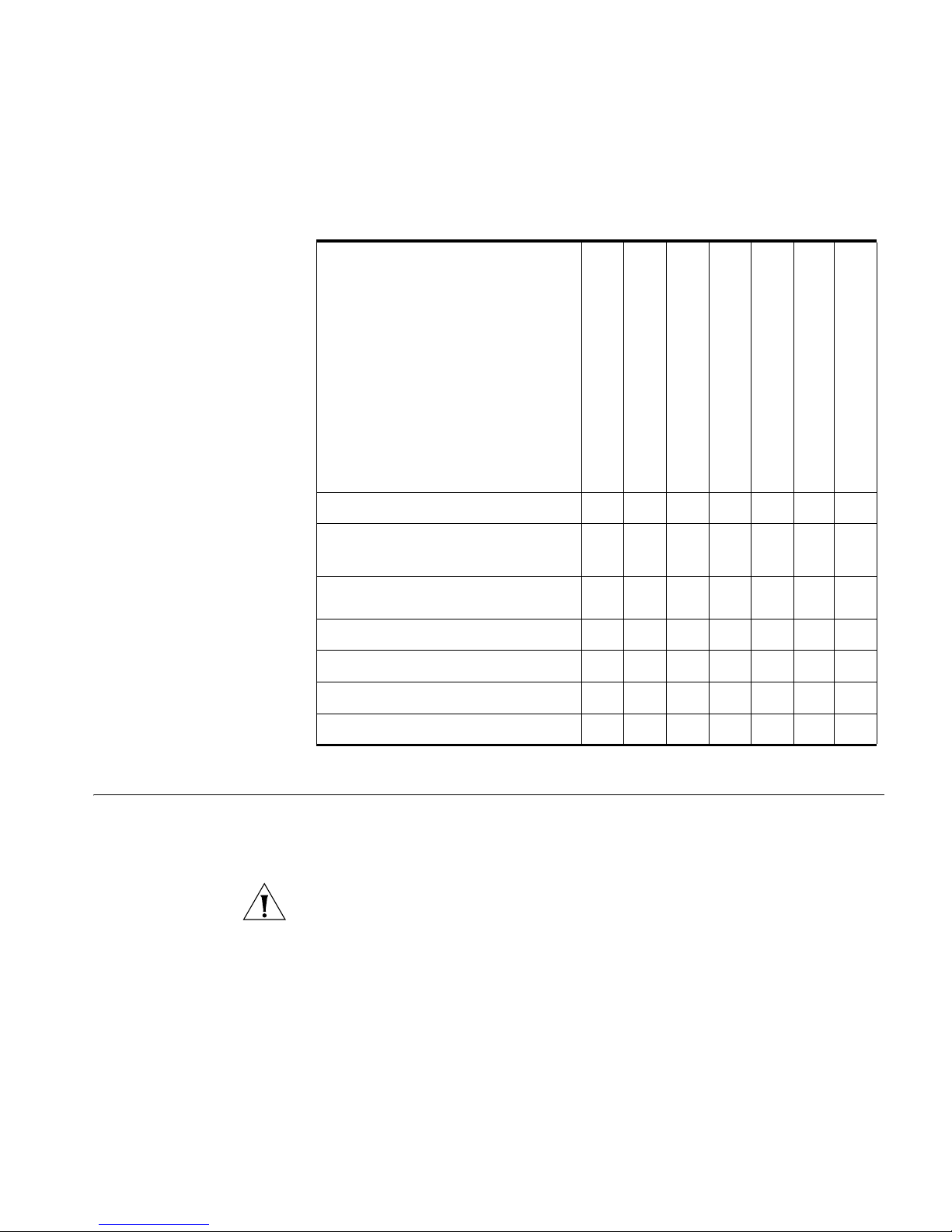
The Switch 5500 Family are mixed media devices. Ta bl e 3 summarizes
what each Switch consists of:
Tab le 3 Switch 5500 Family Hardware
Switch 5500 Family
Switch 5500-SI 28 Port 24 4 1 1
Switch 5500-SI 52 Port 48 4 1 1
Switch 5500-EI 28 Port 24 4 1 1
Switch 5500-EI 52 Port 48 4 1 1
Switch 5500 PWR 28 Port 24 4 1 1
Switch 5500 PWR 52 Port 48 4 1 1
Switch 5500 FX 28 Port 2 24 2 1 1
Switch 5500G-EI 24 Port 24 24* 4† 2 1 1 1
Switch 5500G-EI 48 Port 48 48* 4† 2 1 1 1
Switch 5500G-EI SFP 24 Port 4 24 2 1 1 1
10BASE-T\100BASE-TX Ports
10BASE-T\1000BASE-TX\1000BASE-T Ports
10\100\1000 PoE Ports
100BASE-X SFP Ports
1000BASE-X SFP Ports
Stacking Ports
RJ-45 Console Port
-48V DC RPS Input
Module Slot
*Depending on Power Supply Unit Fitted
†Combo SFP and 10/100/100 Ports
For information about using the software features of the Switch, refer to
the “Command Reference Guide” on the CD-ROM that accompanies the
Switch.

About the Switch 5500 Family 15
Summary of
Hardware Features
Tab l e 4 summarizes the hardware features that are supported by the
Switch 5500 Family.
Tab le 4 Hardware features
Feature Switch 5500 Family
MAC Addresses Up to 16,000 supported
Forwarding Modes Store and Forward
Auto-negotiation Supported on all ports
Auto MDI/MDIX Supported on all ports. If fiber SFP transceivers are used,
Auto MDIX is not supported.
Duplex Modes Half and Full duplex on all ports
Flow Control In full duplex operation, all ports are supported.
Smart Auto-sensing Supported on all copper ports
Traffic Prioritization Supported (IEEE Std 802.1D, 1998 Edition)
Eight traffic queues per port
Power over Ethernet
(Switch 5500)
Power over Ethernet
(Switch 5500G-EI)
Ethernet and Fast
Ethernet Ports
(Switch 5500)
Fast Ethernet and
Gigabit Ethernet Ports
(Switch 5500G-EI)
100BASE-X SFP Ports Supports 100BASE-LX10 10km single-mode and
1000BASE-X Gigabit
Ethernet SFP Ports
RPS Support Connects to -48v DC supply
Mounting 19-inch rack or stand-alone mounting
XRN Up to eight units can be managed as a single unit with
Supported on front panel ports, except SFP ports.
(3CR17171 and 3CR17172 only)
Supported on all front panel ports, except SFP ports,
when fitted with PoE PSUs (3CR17254 and 3CR17255).
Auto-negotiating 10BASE-T/100BASE-TX ports or
100BASE-X ports.
Auto-negotiating 10BASE-T/100BASE-TX/1000BASE-T
and SFP ports.
100BASE-FX 2km multi-mode transceivers.
Supports fiber Gigabit Ethernet short-wave (SX),
long-wave (LX), long-haul (LH70) and copper (T)
transceivers in any combination
one IP address.
16 CHAPTER 1: INTRODUCING THE SUPERSTACK 4 SWITCH 5500 FAMILY
l
Switch 5500 Family
— Front View
Detail
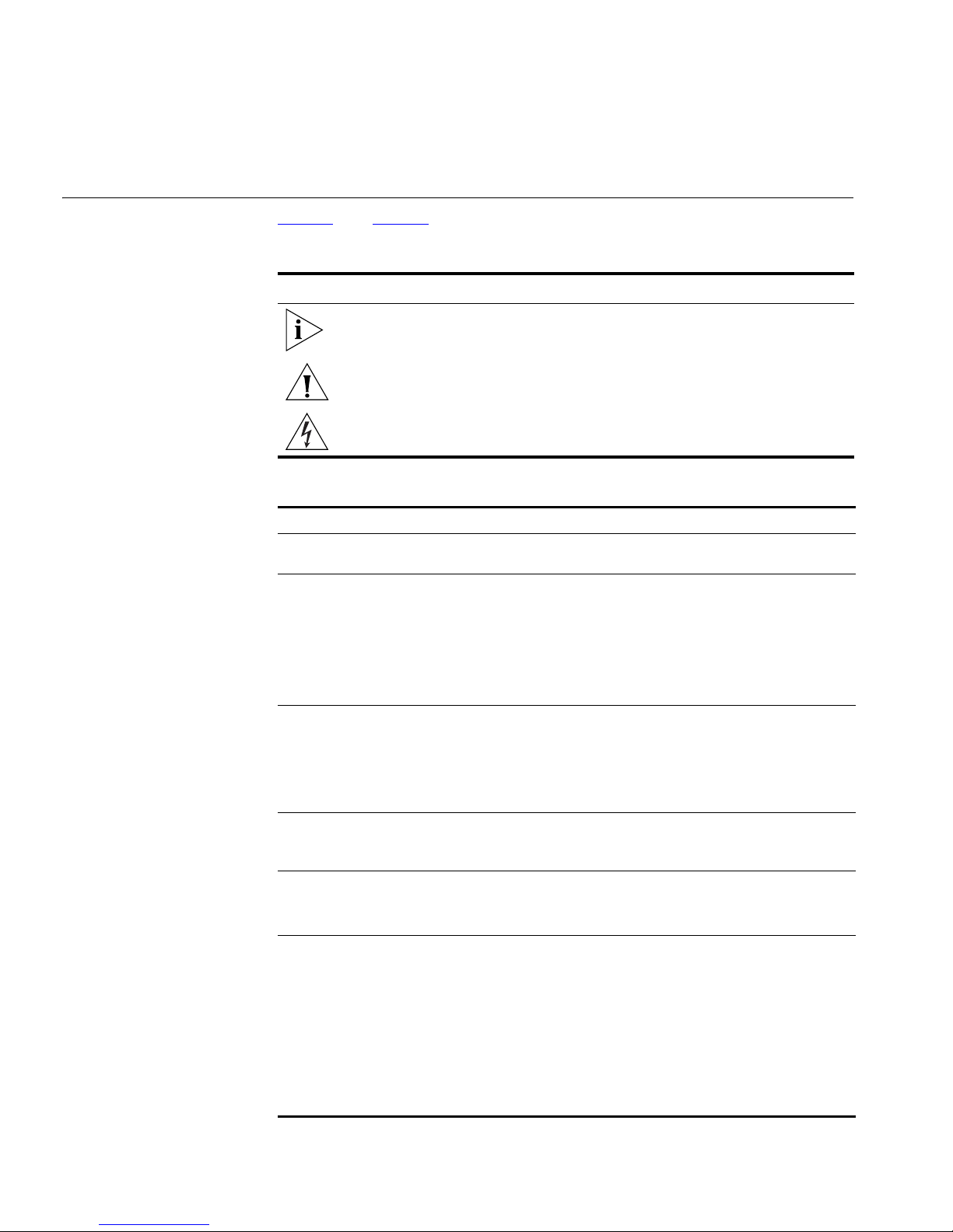
Switch 5500 Figure 1 Switch 5500 SI and EI 28-Port — front view
Port Status LEDs
10/100BASE-TX Ports
Figure 2 Switch 5500 SI and EI 52-Port — front view
Figure 3 Switch 5500-EI 28-Port PWR - front view
1000BASE-X Ports
Port Status LEDs
10/100BASE-TX Ports
Console Port
Unit LED
Mode LED
Conso
RPS LED
Power LED
e Port
1000BASE-X Ports
Unit LED
RPS LED
Mode LED
PWR LED
Port Status LEDs
10/100BASE-TX Ports
1000BASE-X Ports
Console Port
3CR17171-91
Unit LED
SuperStack 4 Switch 5500 PWR 28 Port
Green=Status
Yellow=Packet
Red=PoE
Mode LED
RPS LED
Power LED
Switch 5500 Family — Front View Detail 17
l
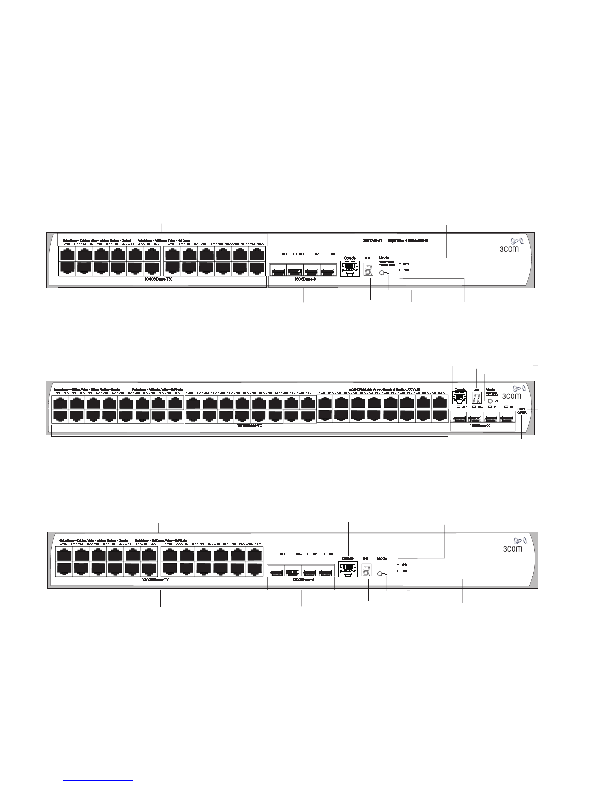
Figure 4 Switch 5500-EI 52-Port PWR - front view
Port Status LEDs
3CR17172-91
10/100BASE-TX Ports
Figure 5 Switch 5500-EI FX 28-Port — front view
Port Status LEDs
Speed
Duplex
100Base-FX
100BASE-FX Ports
1000Base-X
1000BASE-X Ports
10/100/1000BASE-T Ports
Console Port
3CR17181-91
10/100/100BASE-T
Unit LED
Switch 5500G-EI Figure 6 Switch 5500G-EI (24 port) — front view
Conso
e Port
SuperStack 4 Switch 5500 PWR 52 Port
RPS LED
SuperStack 4 Switch 5500-EI 28-Port FX
RPS
Green=Speed
Yellow=Duplex
PWR
Mode LED
Power LED
Unit LED
Mode LED
Green=Status
Yellow=Packet
Red=PoE
1000BASE-X Ports
RPS LED
PWR LED
Port Status LEDs
Status:Green=10Mbps Yellow=10Mbps Flashing=Disabled Packet:Green=FullDuplex Yellow=Half Duplex Power:Green=Delivering Power Yellow=FaultFlashing Green=Over Budget
1 432 5 678 9 10 11 1213 161514 17 18 19 20 21 22 23 24
21
10/100/1000BASE-T Ports
Dual Personality
10/100/1000BASE-T/
1000BASE-X SFP Ports
22 23
Unit LED
Console
24
Console Port
3CR17251-91 SuperStack 4 Switch 5500G-EI 24-Port
Mode:
Unit
Green=Status
100%
80%
Yellow=Packet
60%
Red=POE
40%
20%
Mode LED
PWR LED
PWR
RPS
MOD
STK
Stack LED
Module LED
RPS LED
18 CHAPTER 1: INTRODUCING THE SUPERSTACK 4 SWITCH 5500 FAMILY
Figure 7 Switch 5500G-EI (48 port) — front view
Port Status LEDs
Status:Green=10Mbps Yellow=10Mbps Flashing=Disabled Packet:Green=FullDuplex Yellow=Half Duplex Power:Green=Delivering Power Yellow=FaultFlashing Green=Over Budget
1 432 5 678 9 10 11 1213 161514 17 18 19 20 21 22 23 24 25 282726 29 30 31 32 33 34 35 3637 403938 41 42 43 44 45 46 47 48
Console Port
SuperStack 4 Switch 5500G-EI 48-port
10/100/1000BASE-T Ports
10/100/1000BASE-T/
1000BASE-X SFP Ports
Figure 8 Switch 5500G-EI SFP (24 port) — front view
Port Status LEDs
3
2
14
15
13
1
16
18
4
1000BASE-X:
Green=1000Mbps Flashing Yellow=POST failed
10/100/1000BASE-TX:
S(Speed):Green=1000Mbps Yellow=10/100Mbps
D(Duplex):Green=Full Duplex Yellow=Half Duplex
19
20
7
21
8
9
22
23
10
11
24
12
1000Base-X1000Base-X
6
17
5
3CR17259-91 SuperStack 4 Switch 5500G-EI SFP 24-Port
25/11
26/12
D
S
10/100/1000Base-TX
27/23
D
S
D
S
28/24
S
D
Unit LED
100%
80%
60%
40%
20%
45
46 47
Dual Personality
Power LED
RPS LED
Power LED
Mode LED
Mode:
Green=Status
Yellow=Packet
Red=POE
48
Module LED
RPS LED
PWR
RPS
STK
MOD
PWR
RPS
MOD
STK
Stack
LED
10BASE-T/
100BASE-TX/
1000BASE-T Ports
Mode
LED
1000BASE-X Ports
10/100/1000BASE-TX Ports
Unit LED
Console Port
WARNING: RJ-45 Ports. These are shielded RJ-45 data sockets. They
cannot be used as standard traditional telephone sockets, or to connect
the unit to a traditional PBX or public telephone network. Only connect
RJ-45 data connectors, network telephony systems, or network
telephones to these sockets.
Either shielded or unshielded data cables with shielded or unshielded
jacks can be connected to these data sockets.
The 10BASE-T/100BASE-TX/1000BASE-T ports have RJ-45 connectors and
are configured as Auto MDIX (cross-over).
Stack
LED

Switch 5500 Family — Front View Detail 19
The default state for these ports is auto-negotiation enabled, where the
speed, duplex and flow control modes of a link are automatically
detected to provide the highest available bandwidth with the link partner.
Alternatively, auto-negotiation can be disabled. These ports can be
manually configured to 10 Mbps half duplex, 100 Mbps half duplex,
10 Mbps full duplex or 100 Mbps full duplex. It is not possible to
manually configure a 1000 Mbps link as auto-negotiation is mandatory in
the 1000 Mbps standard. If auto-negotiation is disabled, Auto MDIX
cannot function and the ports are fixed as MDIX (cross-over) mode.
If auto-negotiation is disabled on a 1000 Mbps port, the speed will drop
to the highest available speed. By default this is 100 Mbps.
1000BASE-X SFP Ports The 1000BASE-X SFP (Small Form Factor Pluggable) ports support fiber
Gigabit Ethernet short-wave (SX), long-wave (LX), long-haul (LH70) and
copper (T) SFP Transceivers in any combination. This offers you the
flexibility of using SFP transceivers to provide connectivity between the
Switch and remote 1000 Mbps workgroups or to create a high capacity
aggregated link backbone connection.
100BASE-X SFP Ports
(Switch 5500-EI FX
only)
Console Port The console port allows you to connect a terminal and perform remote or
The default state for these ports is auto-negotiation enabled, where the
speed, duplex and flow control modes are negotiated. As the speed and
duplex modes are fixed by the media type, only the flow control is
negotiated with the link partner. Alternatively, auto-negotiation can be
disabled (except 1000BASE-T where auto-negotiation is mandatory) and
the flow control setting can be manually configured.
The Switch 5500-EI FX has 24 100BASE-X SFP ports. These are 100Mbps
ports that can use multi-mode fiber optic cables of up to 2km and
single-mode fiber optic cables of up to 10km.
Duplex and flow control must be manually configured.
The Switch 5500-EI FX supports copper transceivers on the Gigabit SFP
ports only.
local out-of-band management. As the console port on the Switch is an
RJ-45 port, you will need to connect an RJ-45 to DB9 converter cable to a
standard null modem cable in order to connect a terminal. The default
baud rate is 19,200.

20 CHAPTER 1: INTRODUCING THE SUPERSTACK 4 SWITCH 5500 FAMILY
Unit LED The Unit LED is a seven segment display visible on the front of the Switch.
The Unit LED can be used to diagnose hardware faults, display POST test
ID, display Stack ID, display PoE utilization and software upgrade
information. For information on using the Unit LED for problem solving,
Solving Problems Indicated by LEDs” on page 78.
see “
LEDs Ta bl e 5
status according to color. For information on using the LEDs for problem
solving, see “
Tab le 5 LED behavior
LED Color Indicates
10/100/1000BASE-TX Port LEDs
Speed Green A high speed (1000 Mbps) link is present, blinking off
Duplex Green Full duplex, blinking off for every packet received or
PoE Green Power is being delivered to the port.
10/100BASE-T/TX Ports LEDS
Speed Green A high speed (100 Mbps) link is present, blinking off
lists LEDs visible on the front of the Switch, and how to read their
Checking for Correct Operation of LEDs” on page 40.
for every packet received or transmitted.
Yellow A low speed (10/100 Mbps) link is present, blinking
off for every packet received or transmitted.
Yellow flashing The port has failed POST.
Off No link is present.
transmitted.
Yellow Half duplex, blinking off for every packet received or
transmitted.
Yellow flashing The port has failed POST.
Off No link is present.
Green flashing Port power has exceeded limit or is unable to supply
power due to unit being over budget.
Yellow PoE error, no power supplied on port.
Yellow flashing The port has failed post.
Off No power is being delivered.
for every packet received or transmitted.
Yellow A low speed (10 Mbps) link is present, blinking off for
every packet received or transmitted.
Yellow flashing The port has failed POST.
Off No link is present.

Switch 5500 Family — Front View Detail 21
LED Color Indicates
Duplex Green Full duplex, blinking off for every packet received or
transmitted.
Yellow Half duplex, blinking off for every packet received or
transmitted.
Yellow flashing The port has failed POST.
Off No link is present.
PoE Green Power is being delivered to the port.
Green flashing Port power has exceeded limit or is unable to supply
power due to unit being over budget.
Yellow PoE error, no power supplied on port.
Yellow flashing The port has failed post.
Off No power is being delivered.
1000BASE-X SFP Port LEDs
Speed Green A 1000 Mbps link is present.
Yellow flashing The port has failed post.
Off No link is present.
Duplex Green Full duplex packets are being transmitted/received on
the port.
Yellow Half duplex packets are being transmitted/received on
the port.
Yellow flashing Port failed POST.
Off No links is present.
100BASE-X SFP Port LEDs
Speed Green A 100 Mbps link is present.
Yellow flashing The port has failed post.
Off No link is present.
Duplex Green Full duplex packets are being transmitted/received on
the port.
Yellow Half duplex packets are being transmitted/received on
the port.
Yellow flashing Port failed POST.
Off No links is present.

22 CHAPTER 1: INTRODUCING THE SUPERSTACK 4 SWITCH 5500 FAMILY
LED Color Indicates
Unit LED
Green Power on Self Test (POST) is in progress. During POST
a test ID number appears in the Unit LED (seven
segment display)
or
Software download is in progress. During software
download, a clockwise cycling bar appears in the Unit
LED.
Green flashing The Switch has failed POST. The Unit LED flashes the
number of the test that has failed.
Green flashing ‘f’ There has been a fan failure.
Green flashing ‘t’ The Switch is over temperature and unit temperature
is critical.
Stack LED
Green The XRN stack is functioning in resilient mode. Loop
cable is attached.
Green flashing Switch is not compatible with the other Switches in
the stack.
Yellow The XRN stack is functioning without the loop
connection.
Off Stacking Cables are not connected.
Module LED (Switch 5500G-EI only)
Green The Module is installed and operating normally.
Yellow flashing The Module is installed but not supported or faulty.
Off The Module is not installed.
Mode LED
Duplex Yellow 10/100/1000 Duplex and Activity, 1000 SFP Duplex
and Activity, or Stack Activity.
Speed Green 10/100/1000 Port Speed and Activity, 1000 SFP
Status and Activity, or Stack Status and Activity.
PoE Red 10/100/1000 port showing PoE information.
RPS LED
Green AC and RPS supply connected.
Yellow AC failed or not connected. RPS supply is OK.
Off There is no RPS supply connected.
Switch 5500 Family
— Rear View Detail
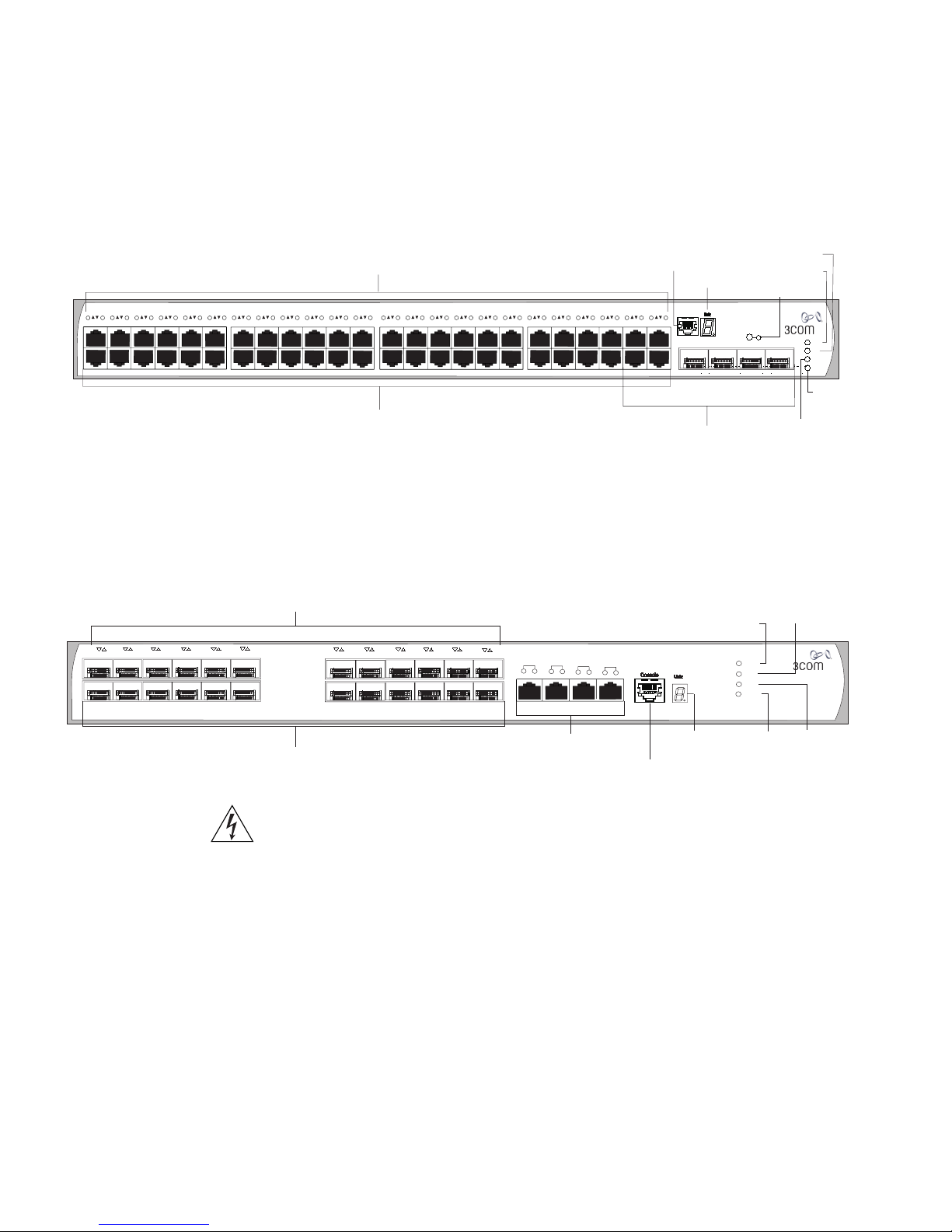
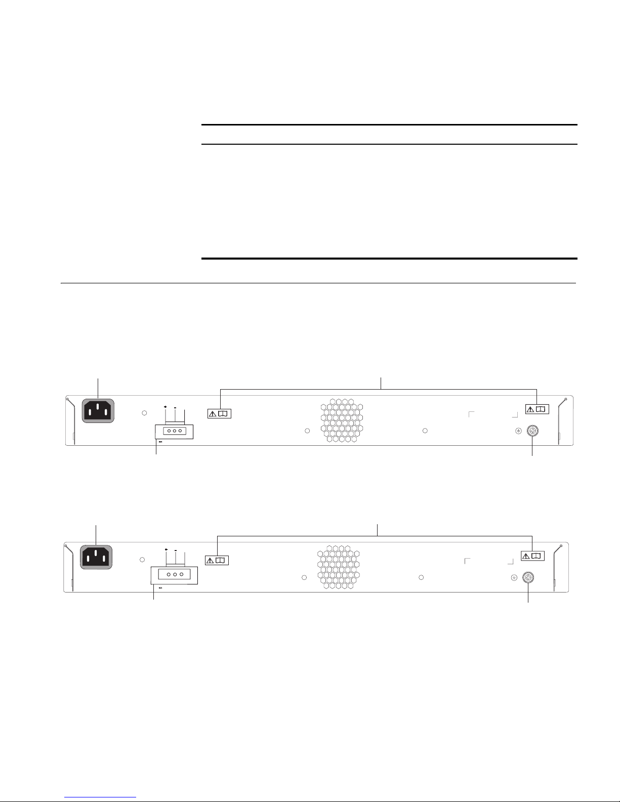
Switch 5500 Figure 9 Switch 5500 SI, EI and FX — rear view
Switch 5500 Family — Rear View Detail 23
LED Color Indicates
PWR LED
Green The Switch is powered-up and operating normally.
Green flashing Self Test (POST) or Software Download is in progress.
Yellow flashing One or more ports have failed POST.
Red The Switch has failed its Power On Self Test.
Off The Switch is not receiving power or there is a fault
with the Power Supply Unit.
Power Socket
100-240V; 50/60Hz; 2.5A
~
Power Socket
100-240V; 50/60Hz; 7.0A
~
NULL
-48 -60V;2.0A
Redundant Power System Socket
NULL
-52 -55V;19.5A
Redundant Power System Socket
Open Book Warning Labels
Earthing Screw
Figure 10 Switch 5500 PWR - rear view
Open Book Warning Labels
Earthing Screw
24 CHAPTER 1: INTRODUCING THE SUPERSTACK 4 SWITCH 5500 FAMILY
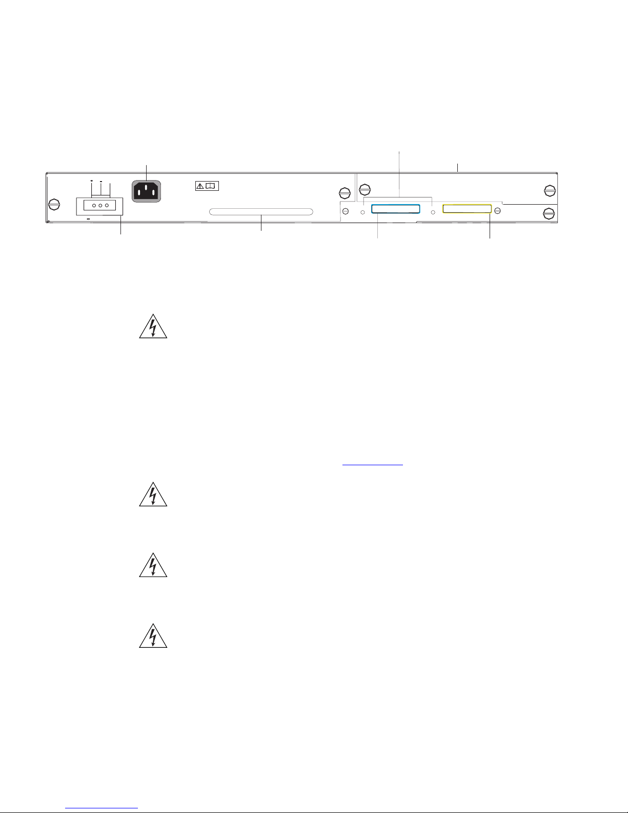
Switch 5500G-EI Figure 11 Switch 5500G-EI — rear view
Power Socket
Switch 5500G PoE PSU 24-Port
NULL
Stack LEDs
Expansion Module Slot
-52 - -55V;19.5A
Redundant Power System Socket
Expansion Module
Slot
Power Socket Each Power Supply automatically adjusts its voltage setting to any supply
Open Book Warning
Labels
UP
Stacking: Green=OK, Flashing Green=Traffic, Yellow=LinkFault,
Handle
Stacking Cable Port (Up)
DOWN
Yellow Flashing=Stack Fault
Stacking Cable Port (Down)
You can use this slot to install an Expansion Module. Contact your
supplier for further information.
WARNING:
When an Expansion Module is not installed, ensure the
blanking plate is fitted by tightening all screws with a suitable tool.
Failure to fit a blanking plate may void the product warranty.
voltage in the range 100-240 VAC.
Before installing or removing any components from the Switch 5500
Family or carrying out any maintenance procedures, you must read the
safety information provided in Appendix A
of this guide.
AVERTISSEMENT: Avant d'installer ou d'enlever tout composant des
commutateurs de la gamme Switch 5500 ou d'entamer une procédure
de maintenance, lisez les informations relatives à la sécurité qui se
trouvent dans l'annexe A de ce guide.
VORSICHT:Bevor Sie Komponenten der Switch 5500-Baureihe
installieren oder deinstallieren und bevor Sie Wartungsarbeiten
ausführen, müssen Sie die in Anhang A dieses Handbuchs aufgeführten
Sicherheitshinweise lesen.
ADVERTENCIA: Antes de instalar o extraer cualquier componente del
Switch 5500 Family o de realizar tareas de mantenimiento, debe leer la
información de seguridad facilitada en el Apéndice A de esta guía.

Switch 5500 Family — Rear View Detail 25
AVVERTENZA: Prima di installare o rimuovere qualsiasi componente
dello Switch 5500 Family o di eseguire qualsiasi procedura di
manutenzione, leggere le informazioni di sicurezza riportate
nell'Appendice A di questa guida.
OSTRZEŻENIE: Przed instalacją lub usunięciem jakichkolwiek elementów
z przełącznika z rodziny 5500 lub przeprowadzeniem prac
konserwacyjnych należy zapoznać się z informacjami o bezpieczeństwie
zawartymi w Załączniku A niniejszego podręcznika.
Redundant Power
System Socket
Stacking Cable Ports
(Switch 5500G-EI)
To protect against internal power supply failure, you can use this socket
to connect the Switch to a -48 DC Redundant Power System.
You can use these ports to connect the following cables:
■ Stacking Cable (3C17262) — which enables you to stack together
two switches up to three rack units apart.
■ Resilient Stacking Cable (3C17263) — which enables you to stack
together two switches up to sixteen rack units apart.
You can stack together any combination of 5500G-EI 24 port and 48 port
units, up to a maximum of eight units.
For more information on how to connect a stacking cable to your Switch
units, please refer to the Installation Guide that accompanies your cable.
It is not possible to create a Fabric by interconnecting a 3Com Switch
5500 with any other 3Com device (such as a 5500G-EI) or mix Enhanced
Image (EI) Switch 5500 units with Standard Image (SI) units.

26 CHAPTER 1: INTRODUCING THE SUPERSTACK 4 SWITCH 5500 FAMILY
Default Settings Ta bl e 6 shows the default settings for the Switch 5500 Family. If you
initialize one of the Switch units, it is returned to these defaults.
Tab le 6 Default Settings
Feature Switch 5500 Family
Port Status Enabled
Port Speed Auto-negotiated
Duplex Mode Auto-negotiated
Power over Ethernet Enabled on the Switch 5500G-EI (when a PoE
PSU is installed)
Flow Control Auto-negotiated
Broadcast Storm Control Enabled
Virtual LANs (VLANs) All ports belong to the untagged Default VLAN
(VLAN 1) with IEEE Std 802.1Q-1998 learning
operational.
Management VLAN VLAN 1
Multicast Filtering IGMP filtering enabled
Rapid Spanning Tree Protocol Enabled
Fast Start Enabled
RMON Alarm Enabled
Link Aggregation Control
Protocol (LACP)
Spanning Tree Protocol Enabled
Smart Auto-sensing Enabled
Disabled per port

2
INSTALLING THE SWITCH
This chapter contains the information you need to install and set up the
Switch 5500. It covers the following topics:
■ Package Contents
■ Choosing a Suitable Site
■ Rack-mounting
■ Connecting a Redundant Power Supply
■ Placing Units On Top of Each Other
■ The Power-up Sequence
■ SFP Operation
■ Packing and Shipping the Switch 5500G-EI
WARNING: Safety Information. Before installing or removing any
components from the Switch 5500 or carrying out any maintenance
procedures, you must read the safety information provided in Appendix A
of this guide.
AVERTISSEMENT: Consignes de sécurité. Avant d'installer ou d'enlever
tout composant de Switch 5500 ou d'entamer une procédure de
maintenance, lisez les informations relatives à la sécurité qui se trouvent
dans l'Appendice A de ce guide.
VORSICHT: Sicherheitsinformationen. Bevor Sie Komponenten aus
dem Switch 5500 entfernen oder der Switch 5500 hinzufuegen oder
Instandhaltungsarbeiten verrichten, lesen Sie die
Sicherheitsanweisungen, die in Anhang A in diesem Handbuch
aufgefuehrt sind.
ADVERTENCIA: Información de seguridad. Antes de instalar o extraer
cualquier componente del Switch 5500 o de realizar tareas de
mantenimiento, debe leer la información de seguridad facilitada en el
Apéndice A de esta guía del usuario.

28 CHAPTER 2: INSTALLING THE SWITCH
AVVERTENZA: Informazioni di sicurezza. Prima di installare o
rimuovere qualsiasi componente dal Switch 5500 o di eseguire qualsiasi
procedura di manutenzione, leggere le informazioni di sicurezza riportate
nell'Appendice A della presente guida per l'utente.
OSTRZEŻENIE: Informacje o zabezpieczeniach. Przed instalacją lub
usunięciem jakichkolwiek elementów z product lub przeprowadzeniem
prac konserwacyjnych należy zapoznać się z informacjami o
bezpieczeństwie zawartymi w Załączniku A niniejszego podręcznika.
Package Contents The Switch 5500 packaging contains the following for all units:
■ Switch Unit
■ RPS -48V DC Connector
■ CD ROM (includes documentation for your Switch)
■ Getting Started Guide (this guide)
■ Release Notes
■ Warranty Information
■ 3 x Serial Number Labels
■ RPS Flyer
■ Power Cord
■ Console Cable (RJ-45)
■ 4 x Rubber Feet
Tab l e 7
below details the packaging contents specific to each unit in the
Switch 5500 Family.
Tab le 7 Package Contents
Blanking Plate
Choosing a Suitable Site 29
Switch 5500-SI 28 and 52 Port
Switch 5500-EI 28 and 52 Port
Switch 5500 PWR 28 and 52 Port
Switch 5500 FX 28 Port
Switch 5500G-EI 24 Port
Switch 5500G-EI 48 Port
✓ ✓ ✓
Switch 5500G-EI SFP 28 Port
Choosing a Suitable
Site
12A RPS Connector and Backshell
(incl. cable tie and earthing lead)
25A RPS Connector and Backshell
(incl. cable tie and earthing lead)
2 x Front Securing Brackets
2 x Back Securing Brackets
4 x Screws
6 x Screws
✓ ✓ ✓
✓ ✓ ✓ ✓
✓ ✓ ✓ ✓ ✓ ✓ ✓
✓ ✓ ✓ ✓
✓ ✓ ✓
✓ ✓ ✓ ✓
The Switch 5500 Family is suited for use in an internal wiring closet, a
network room, or telecommunications room, where it can be mounted in
a standard 19-inch equipment rack, or free-standing.
CAUTION: Ensure that the ventilation holes are not obstructed.
When deciding where to position the Switch, ensure that:
■ Cabling is located away from:
■ The Switch is accessible and cables can be connected easily.
■ sources of electrical noise such as radios, transmitters and
broadband amplifiers.
■ power lines and fluorescent lighting fixtures.
30 CHAPTER 2: INSTALLING THE SWITCH
■ Water or moisture cannot enter the case of the Switch.
■ Air flow is not restricted around the Switch or through the vents in the
■ Air temperature around the Switch does not exceed 40 °C (104 °F).
If the Switch is installed in a 19-inch rack or closed assembly its local air
temperature may be greater than room ambient temperature.
■ The air is as free from dust as possible.
■ The Switch is situated away from sources of conductive (electrical)
■ The unit is installed in a clean, air conditioned environment.
■ The AC supply used by the Switch is separate to that used by units
side of the Switch. 3Com recommends that you provide a minimum of
25 mm (1 in.) clearance.
dust, for example laser printers.
that generate high levels of AC noise, for example air conditioning
units.
■ No more than four Switch units are placed on top of one another, if
the units are free-standing.
Rack-mounting The Switch 5500 is 1U high and will fit in most standard 19-inch racks.
CAUTION: Disconnect all cables from the Switch before continuing.
Remove all self adhesive pads from the underside of the Switch if they
have been fitted.
CAUTION: If you use a shelf or support ensure that it will not obstruct
the air flow through the side panels of the Switch.
Switch 5500 (non
PoE)
To rack-mount your Switch 5500 (non PoE):
1 Place the Switch the right way up on a hard flat surface, with the front
facing towards you.
2 Locate a securing bracket over the mounting holes on one side of the
front of the Switch, as shown in Figure 12
.
 Loading...