

3Com Switch 4900, 3C17700, Switch 4900 SX, 3C17702, Switch 4924 Getting Started Manual
...
SuperStack® 3
Switch 4900 Series
Getting Started Guide
Switch 4900 (3C17700)
Switch 4900 SX (3C17702)
Switch 4924 (3C17701)
Switch 4950 (3C17706)
http://www.3com.com/
Part No. DUA1770-0AAA04
Published August 2002

3Com Corporation
5400 Bayfront Plaza
Santa Clara, California
95052-8145
Copyright © 2002, 3Com Technologies. All rights reserved. No part of this documentation may be reproduced
in any form or by any means or used to make any derivative work (such as translation, transformation, or
adaptation) without written permission from 3Com Technologies.
3Com Technologies reserves the right to revise this documentation and to make changes in content from time
to time without obligation on the part of 3Com Technologies to provide notification of such revision or
change.
3Com Technologies provides this documentation without warranty, term, or condition of any kind, either
implied or expressed, including, but not limited to, the implied warranties, terms or conditions of
merchantability, satisfactory quality, and fitness for a particular purpose. 3Com may make improvements or
changes in the product(s) and/or the program(s) described in this documentation at any time.
If there is any software on removable media described in this documentation, it is furnished under a license
agreement included with the product as a separate document, in the hard copy documentation, or on the
removable media in a directory file named LICENSE.TXT or !LICENSE.TXT. If you are unable to locate a copy,
please contact 3Com and a copy will be provided to you.
UNITED STATES GOVERNMENT LEGEND
If you are a United States government agency, then this documentation and the software described herein are
provided to you subject to the following:
All technical data and computer software are commercial in nature and developed solely at private expense.
Software is delivered as “Commercial Computer Software” as defined in DFARS 252.227-7014 (June 1995) or
as a “commercial item” as defined in FAR 2.101(a) and as such is provided with only such rights as are
provided in 3Com’s standard commercial license for the Software. Technical data is provided with limited rights
only as provided in DFAR 252.227-7015 (Nov 1995) or FAR 52.227-14 (June 1987), whichever is applicable.
You agree not to remove or deface any portion of any legend provided on any licensed program or
documentation contained in, or delivered to you in conjunction with, this User Guide.
Unless otherwise indicated, 3Com registered trademarks are registered in the United States and may or may not
be registered in other countries.
3Com, the 3Com logo, and SuperStack are registered trademarks of 3Com Corporation.
IEEE and 802 are registered trademarks of the Institute of Electrical and Electronics Engineers, Inc.
Intel and Pentium are registered trademarks of Intel Corporation. Microsoft, MS-DOS, Windows, and Windows
NT are registered trademarks of Microsoft Corporation. Novell and NetWare are registered trademarks of
Novell, Inc. UNIX is a registered trademark in the United States and other countries, licensed exclusively
through X/Open Company, Ltd.
Netscape Navigator is a registered trademark of Netscape Communications.
JavaScript is a trademark of Sun Microsystems.
All other company and product names may be trademarks of the respective companies with which they are
associated.
ENVIRONMENTAL STATEMENT
It is the policy of 3Com Corporation to be environmentally-friendly in all operations. To uphold our policy, we
are committed to:
Establishing environmental performance standards that comply with national legislation and regulations.
Conserving energy, materials and natural resources in all operations.
Reducing the waste generated by all operations. Ensuring that all waste conforms to recognized environmental
standards. Maximizing the recyclable and reusable content of all products.
Ensuring that all products can be recycled, reused and disposed of safely.
Ensuring that all products are labelled according to recognized environmental standards.
Improving our environmental record on a continual basis.
End of Life Statement
3Com processes allow for the recovery, reclamation and safe disposal of all end-of-life electronic components.
Regulated Materials Statement
3Com products do not contain any hazardous or ozone-depleting material.
Environmental Statement about the Documentation
The documentation for this product is printed on paper that comes from sustainable, managed forests; it is
fully biodegradable and recyclable, and is completely chlorine-free. The varnish is environmentally-friendly, and
the inks are vegetable-based with a low heavy-metal content.

CONTENTS
ABOUT THIS GUIDE
Conventions 8
Related Documentation 9
Accessing Online Documentation 9
Product Registration 10
Documentation Comments 10
1 INTRODUCING THE
S
UPERSTACK 3 SWITCH 4900 SERIES
About the Switches 12
Summary of Hardware Features 13
Switch — Front View Detail 14
100/1000BASE-T and 10/100/1000BASE-T Ports 16
1000BASE-SX Ports 16
GBIC Ports 16
LEDs 17
Switch — Rear View Detail 18
Unit Information Label 19
Power Socket 19
Redundant Power System Socket 19
Console Port 20
Expansion Module Slot 20
Default Settings 20
2 INSTALLING THE SWITCH
Package Contents 22
Choosing a Suitable Site 22
Rack-mounting 23
Placing Units On Top of Each Other 24
Creating an XRN Distributed Fabric 24
How To Interconnect Units 25

Rules For Interconnecting Units 25
The Power-up Sequence 26
Powering-up the Switch 26
Checking for Correct Operation of LEDs 26
Connecting a Redundant Power System 27
Choosing the Correct 10/100/1000BASE-T Cables 27
Choosing the Correct Fiber Cables 28
Switch 4950 — GBIC Operation 29
Approved GBIC Transceivers 29
Inserting a GBIC Transceiver 29
3 SETTING UP FOR MANAGEMENT
Setting Up Overview 34
IP Configuration 35
Preparing for Management 36
Manually Configuring IP Information 37
Connecting to a Front Panel Port 37
Connecting to the Console Port 40
Viewing Automatically Configured IP Information 43
Using 3Com Network Supervisor 43
Connecting to the Console Port 44
Methods of Managing a Switch 46
Command Line Interface Management 46
Web Interface Management 47
SNMP Management 47
Setting Up Command Line Interface Management 48
CLI Management via the Console Port 48
CLI Management over the Network 48
Setting Up Web Interface Management 49
Pre-requisites 49
Web Management Over the Network 50
Setting Up SNMP Management 51
Pre-requisites 51
Default Users and Passwords 51
Changing Default Passwords 52

4 PROBLEM SOLVING
Solving Problems Indicated by LEDs 54
Solving Hardware Problems 55
Solving Communication Problems 57
Solving Software Upgrade Problems 58
A SAFETY INFORMATION
Important Safety Information 60
L’information de Sécurité Importante 63
Wichtige Sicherheitsinformationen 66
B PIN-OUTS
Null Modem Cable 69
PC-AT Serial Cable 69
Modem Cable 70
RJ-45 Pin Assignments 70
C TECHNICAL SPECIFICATIONS
D TECHNICAL SUPPORT
Online Technical Services 75
World Wide Web Site 75
3Com Knowledgebase Web Services 75
3Com FTP Site 76
Support from Your Network Supplier 76
Support from 3Com 77
Email Support 77
Telephone Support 77
Returning Products for Repair 79
INDEX
REGULATORY NOTICES

ABOUT THIS GUIDE
This guide provides all the information you need to install and use the
following Switches in their default state:
■ SuperStack
■ SuperStack
■ SuperStack
■ SuperStack
This guide is intended for use with all the 4900 Series Switches listed
above. For illustrative purposes all pictures and example screens show the
4900 model, however, all procedures apply to all the other Switches listed
unless otherwise stated.
®
3 Switch 4900 (3C17700)
®
3 Switch 4900 SX (3C17702)
®
3 Switch 4924 (3C17701)
®
3 Switch 4950 (3C17706)
The guide is intended for use by network administrators who are
responsible for installing and setting up network equipment;
consequently, it assumes a basic working knowledge of LANs (Local Area
Networks).
If the information in the release notes that are shipped with your product
differ from the information in this guide, follow the instructions in the
release notes.
Most user guides and release notes are available in Adobe Acrobat
Reader Portable Document Format (PDF) or HTML on the 3Com
World Wide Web site:
http://www.3com.com/
8 ABOUT THIS GUIDE
Conventions Tab l e 1 and Ta bl e 2 list conventions that are used throughout this guide.
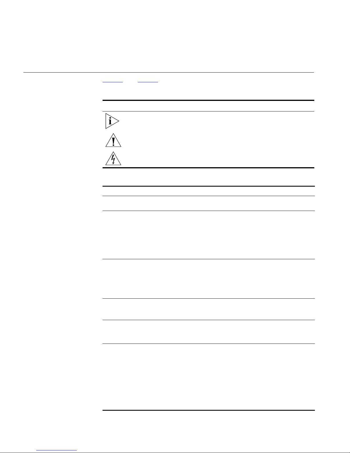
Tab le 1 Notice Icons
Icon Notice Type Description
Information note Information that describes important features or
instructions.
Caution Information that alerts you to potential loss of data or
potential damage to an application, system, or device.
Warning Information that alerts you to potential personal
injury.
Tab le 2 Text Conventions
Convention Description
Screen displays This typeface represents information as it appears on the
screen.
Syntax The word “syntax” means that you must evaluate the syntax
provided and then supply the appropriate values for the
placeholders that appear in angle brackets. Example:
To change your password, use the following syntax:
system password <password>
In this example, you must supply a password for <password>.
Commands The word “command” means that you must enter the
command exactly as shown and then press Return or Enter.
Commands appear in bold. Example:
To display port information, enter the following command:
bridge port detail
The words “enter”
and “type”
Keyboard key names If you must press two or more keys simultaneously, the key
Words in italics Italics are used to:
When you see the word “enter” in this guide, you must type
something, and then press Return or Enter. Do not press
Return or Enter when an instruction simply says “type.”
names are linked with a plus sign (+). Example:
Press Ctrl+Alt+Del
■ Emphasize a point.
■ Denote a new term at the place where it is defined in the
text.
■ Identify menu names, menu commands, and software
button names. Examples:
From the Help menu, select Contents.
Click OK.

Related Documentation 9
Related
Documentation
In addition to this guide, each Switch documentation set includes the
following:
■ SuperStack 3 Management Quick Reference Guide
This guide contains:
■ a list of software features supported by each Switch.
■ a summary of the web interface and command line interface
commands for the Switch.
■ Release Notes
These notes provide information about the current software release,
including new features, modifications, and known problems.
■ SuperStack 3 Switch Implementation Guide
This guide contains information on the features supported by your
Switch and how they can be used to optimize your network. It is
supplied in PDF format on the CD-ROM that accompanies the Switch.
■ Management Interface Reference Guide
This guide provides detailed information about the web interface and
command line interface that enable you to manage the Switch. It is
supplied in HTML format on the CD-ROM that accompanies the
Switch.
Accessing Online
Documentation
There are other publications you may find useful:
■ Documentation accompanying the Advanced Redundant Power
System.
■ Documentation accompanying the Expansion Modules.
■ Documentation accompanying 3Com Network Supervisor. This is
supplied on the CD-ROM that accompanies the Switch.
The CD-ROM supplied with your Switch contains the following online
documentation:
■ SuperStack 3 Switch Implementation Guide (PDF format)
■ SuperStack 3 Switch Management Interface Reference Guide (HTML
format)
■ Other documentation relating to the Switch 4900 Series (PDF format)
10 ABOUT THIS GUIDE
To access the online documentation from the CD-ROM:
1 Insert the CD-ROM into the relevant CD-ROM drive. If your PC has
auto-run enabled, a splash screen will be displayed automatically.
2 Select the Documentation section from the contents page.
If the online documentation is to be accessed from a local drive or server,
you will need to access the CD-ROM contents via the root directory and
copy the files from the CD-ROM to a suitable directory.
■ The HTML Reference Guide is stored in the Docs/referenceguide
on the CD-ROM. The documentation is accessed using the index.htm
file.
■ The PDF Implementation Guide is stored in the
Docs/implementation directory of the CD-ROM.
3Com recommends that you copy the Docs/referenceguide
directory as a whole to maintain the structure of the files.
Product
Registration
Documentation
Comments
You can register your SuperStack 3 Switch on the 3Com Web site to
receive up-to-date information on your product:
http://support.3com.com/registration/frontpg.pl
Your suggestions are very important to us. They will help make our
documentation more useful to you. Please e-mail comments about this
document to 3Com at:
pddtechpubs_comments@3com.com
Please include the following information when commenting:
■ Document title
■ Document part number (on the title page)
■ Page number (if appropriate)
Example:
Part Number DUA1770-0AAA0x
SuperStack 3 Switch 4900 Series Getting Started Guide
Page 21

1
INTRODUCING THE
S
UPERSTACK 3 SWITCH 4900 SERIES
This chapter contains introductory information about the Switch 4900,
4900 SX, 4924 and 4950 and how they can be used in your network. It
covers summary information about the hardware.
The information for all the Switches in the Switch 4900 Series is the same
unless otherwise stated.
■ About the Switches
■ Summary of Hardware Features
■ Switch — Front View Detail
■ 100/1000BASE-T and 10/100/1000BASE-T Ports
■ 1000BASE-SX Ports
■ GBIC Ports
■ LEDs
■ Switch — Rear View Detail
■ Unit Information Label
■ Power Socket
■ Redundant Power System Socket
■ Console Port
■ Expansion Module Slot
■ Default Settings

12 CHAPTER 1: INTRODUCING THE SUPERSTACK 3 SWITCH 4900 SERIES
About the Switches ■ The Switch 4900 connects your existing 100 Mbps devices and
high-performance workgroups with a 1000 Mbps copper backbone or
server connection.
■ The Switch 4900 SX connects your existing 1000 Mbps devices and
high-performance workgroups with a 1000BASE-SX fiber backbone or
server connection.
■ The Switch 4924 connects your existing 10 Mbps and 100 Mbps
devices and high-performance workgroups to a 1000 Mbps copper
backbone or server connection.
■ The Switch 4950 is a 10/100/1000 Mbps mixed media device that
allows you to connect your existing 10/100/1000 Mbps devices and
high-performance workgroups to a fiber or copper gigabit backbone
or server connection.
You can also interconnect any combination of two Switches from the
®
SuperStack
XRN Distributed Fabric. This allows you to create a highly resilient core
around which you can build your network. For more information about
interconnecting Switches, see “Creating an XRN Distributed Fabric”
page 24
use it in your network, refer to the Implementation Guide on the
CD-ROM that accompanies the Switch.
4900 Series or 3Com Switch 4050/4060 range to create an
. For more information about 3Com XRN Technology and how to
on
For information about using the software features of the Switch, refer to
the “SuperStack 3 Switch Management Interface Reference Guide” on
the CD-ROM that accompanies the Switch.

About the Switches 13
Summary of
Hardware Features
Tab l e 3 summarizes the hardware features that are supported by the
Switches.
Tab le 3 Hardware features
Feature Switch 4900 Series
Fast Ethernet
and Gigabit
Ethernet Ports
Addresses ■ Up to 12,000 supported
Forwarding
Modes
Duplex Modes ■ Half duplex only supported on
Flow Control Supported on all ports
Smart
auto-sensing
Tra ff ic
Prioritization
Layer 3
Switching
RPS Support Connects to SuperStack 3 Advanced Redundant Power System
XRN Support eXpandable Resilient Networking (XRN) support. Allows
Mounting 19-inch rack or stand-alone mounting
Switch 4900: 12 Auto-negotiating 100BASE-TX/1000BASE-T
ports
Switch 4900 SX: 12 Auto-negotiating 1000BASE-SX ports
Switch 4924: 24 Auto-negotiating
10BASE-T/100BASE-TX/1000BASE-T ports
Switch 4950: 12 Auto-negotiating
10BASE-T/100BASE-TX/1000BASE-T, 6 1000BASE-SX and
6 GBIC ports
■ Up to 64 permanent entries
Store and Forward
10BASE-T/100BASE-TX/1000BASE-T ports in 10/100 Mbps
mode
■ All 1000 Mbps ports are full duplex only
■ Supported on all 10BASE-T/100BASE-TX/1000BASE-T ports
■ Not supported on 1000BASE-SX and GBIC ports
Supported (IEEE Std 802.1D, 1998 Edition)
Four traffic queues per port
Support for wire-speed IP routing
(ARPS) (3C16071B)
interconnection of two units to create a Distributed Fabric.
14 CHAPTER 1: INTRODUCING THE SUPERSTACK 3 SWITCH 4900 SERIES
Switch — Front
View Detail
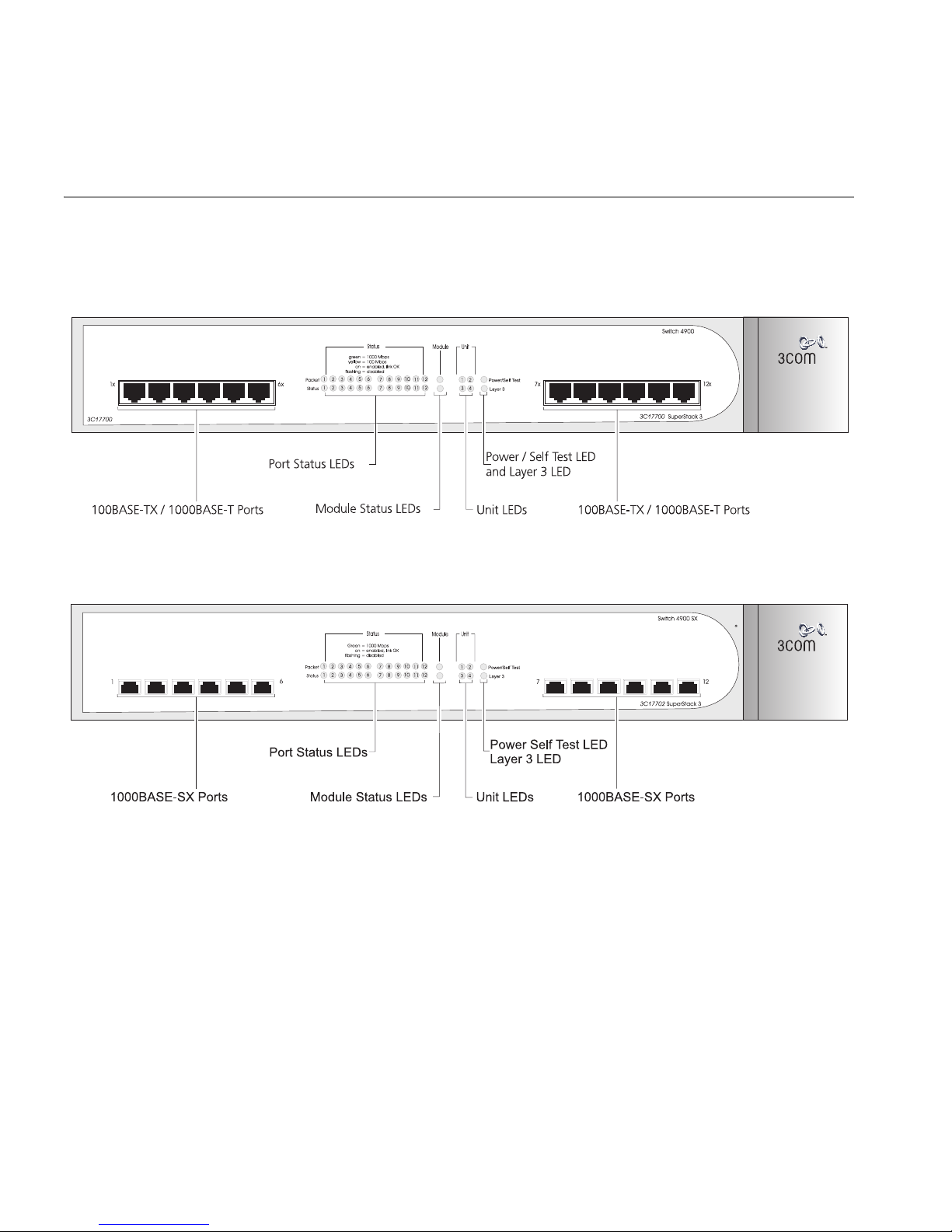
Figure 1 Switch 4900 — front view
Figure 2 Switch 4900 SX — front view
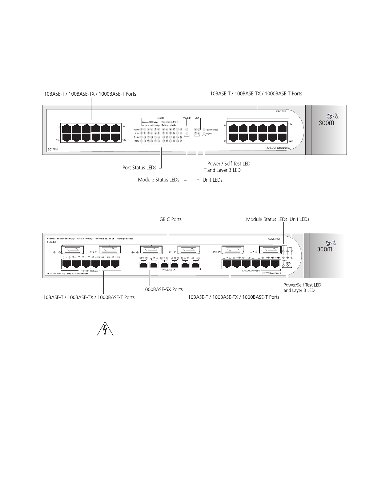
Figure 3 Switch 4924 — front view
Figure 4 Switch 4950 — front view
Switch — Front View Detail 15
WARNING: RJ-45 Ports. These are shielded RJ-45 data sockets. They cannot
be used as standard traditional telephone sockets, or to connect the unit to a
traditional PBX or public telephone network. Only connect RJ-45 data
connectors, network telephony systems, or network telephones to these
sockets.
Either shielded or unshielded data cables with shielded or unshielded
jacks can be connected to these data sockets.
16 CHAPTER 1: INTRODUCING THE SUPERSTACK 3 SWITCH 4900 SERIES
100/1000BASE-T and
10/100/1000BASE-T
Ports
The 100BASE-TX/1000BASE-T and 10BASE-T/100BASE-TX/1000BASE-T
ports have RJ-45 connectors and are configured as Auto MDIX
(cross-over).
The default state for these ports is auto-negotiation enabled, where the
speed, duplex and flow control modes of a link are automatically
detected to provide the highest available bandwidth with the link partner.
Alternatively, auto-negotiation can be disabled. These ports can be
manually configured to 10 Mbps half duplex (if supported), 100 Mbps
half duplex, 10 Mbps full duplex (if supported), or 100 Mbps full duplex.
It is not possible to manually configure a 1000BASE-T link as
auto-negotiation is mandatory in the 1000BASE-T standard.
The maximum segment length is 100 m (328 ft) over Category 5 twisted
pair cable.
1000BASE-T operation only supports full-duplex mode.
10BASE-T (10 Mbps) is only supported on Switch 4924 and 4950.
1000BASE-SX Ports The default state for these ports is auto-negotiation enabled, where the
speed, duplex and flow control modes are negotiated. As the speed and
duplex modes are fixed by the media type, only the flow control is
negotiated with the link partner. Alternatively, auto-negotiation can be
disabled and the flow control setting can be manually configured.
1000BASE-SX ports do not support auto-negotiation of speed and only
support full duplex mode.
GBIC Ports GBIC ports support fiber Gigabit Ethernet short-wave (SX), long-wave
(LX) and long-haul (LH70) GBIC transceivers in any combination. This
offers you the flexibility of using GBIC transceivers to provide connectivity
between the Switch and remote 1000 Mbps workgroups or to create a
high capacity aggregated link backbone connection.
The default state for these ports is auto-negotiation enabled, where the
speed, duplex and flow control modes are negotiated. As the speed and
duplex modes are fixed by the media type, only the flow control is
negotiated with the link partner. Alternatively, auto-negotiation can be
disabled and the flow control setting can be manually configured.

Switch — Front View Detail 17
LEDs Ta bl e 4 lists LEDs visible on the front of the Switch, and how to read their
status according to color. For information on using the LEDs for problem
solving, see “Checking for Correct Operation of LEDs”
Tab le 4 LED behavior
LED Color Indicates
Port Status LEDs
Packet Yellow Packets are being transmitted/received on the port.
Off No packets are being transmitted/received on the port.
Status Green A high speed (1000 Mbps) link is present, and the port
is enabled.
Green flashing A high speed (1000 Mbps) link is present, but the port
is disabled.
Yellow A low speed (100 Mbps on 4900, 10/100 Mbps on
4924/4950) link is present, and the port is enabled.
(Not applicable on 4900 SX.)
Yellow flashing A low speed (100 Mbps on 4900, 10/100 Mbps on
4924/4950) link is present, but the port is disabled.
(Not applicable on 4900 SX.)
Off No link is present.
Module Status LEDs
Green The Module is installed and supported. The Link Status
has been determined for a single port Module.
Yellow The Module is installed and supported. The Module
has multi-ports or there is no Link for a single port
Module.
Yellow flashing The Module is installed but not supported. Note that
the Switch will continue to operate normally.
Off The Module is not installed.
Unit LEDs
1–4 Green Determines the identity of the Switch when
interconnected to another Switch to create an XRN
Distributed Fabric and that a link is present.
Off A fault has occurred.
Power/Self Test LED
Green The Switch is powered-up and operating normally.
Green flashing The Switch is either downloading software or is
initializing (which includes running a Power On Self
Test).
Yellow The Switch has failed its Power On Self Test.
Off The Switch is not receiving power.
on page 26.
18 CHAPTER 1: INTRODUCING THE SUPERSTACK 3 SWITCH 4900 SERIES
LED Color Indicates
Layer 3 LED
Green The Switch software supports Layer 3.
Off The Switch software does not support Layer 3.
Switch — Rear
View Detail
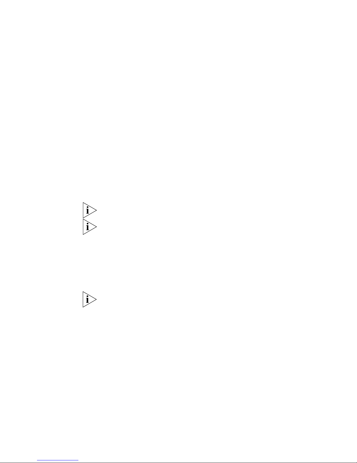
Figure 5 Switch 4900 — rear view
Figure 6 Switch 4900 SX — rear view
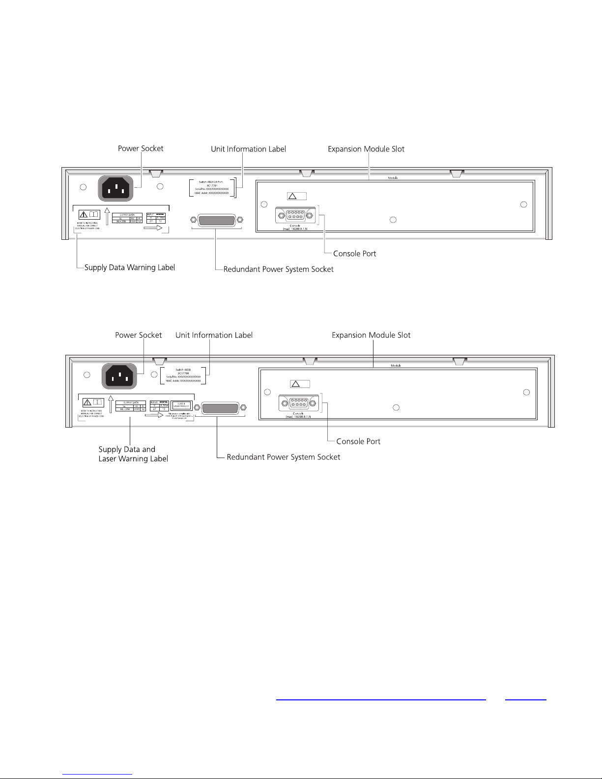
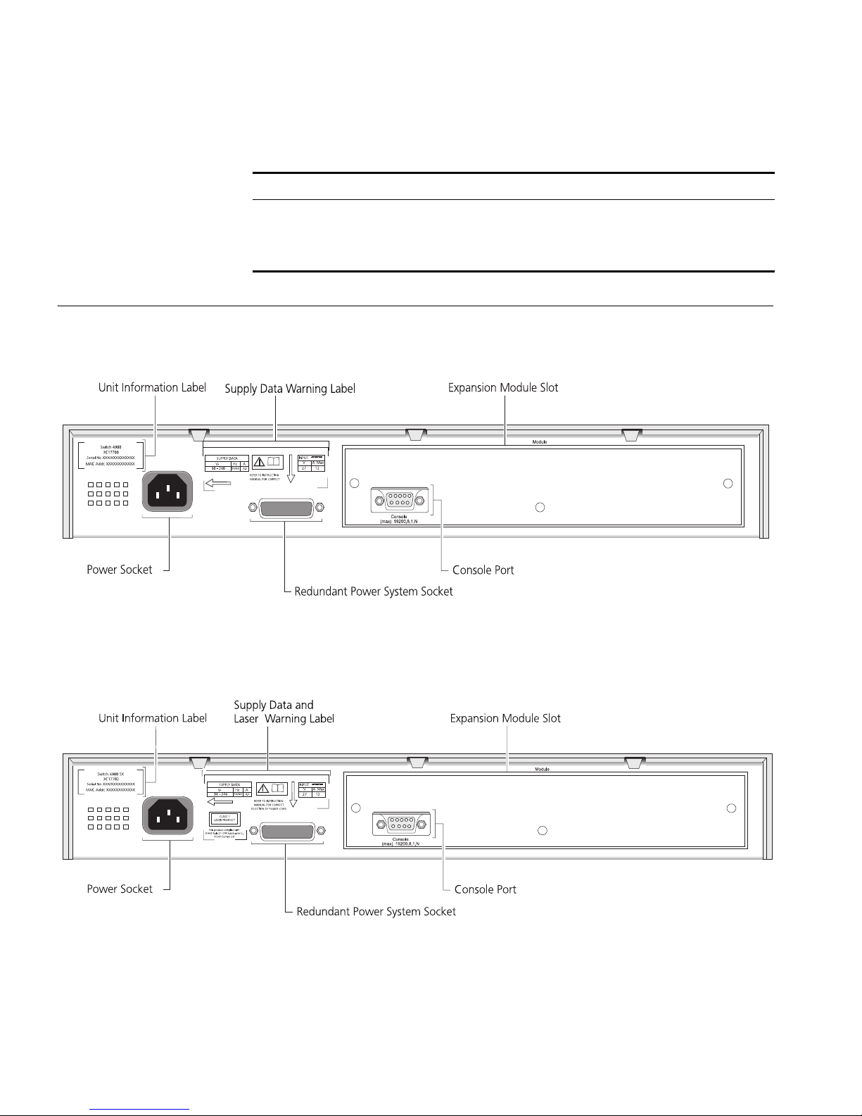
Figure 7 Switch 4924 — rear view
Figure 8 Switch 4950 — rear view
Switch — Rear View Detail 19
Unit Information
Label
This label shows the following:
■ The 3Com product name of the Switch
■ The 3Com 3C number of the Switch
■ The unique MAC address (Ethernet address) of the Switch
■ The serial number of the Switch
You may need this information for fault reporting purposes.
Power Socket The Switch automatically adjusts its power setting to any supply voltage
in the range 90-240 VAC.
Redundant Power
System Socket
To protect against internal power supply failure, you can use this socket
to connect a SuperStack 3 Advanced Redundant Power System (RPS) to
the Switch. See “Connecting a Redundant Power System”
on page 27.
20 CHAPTER 1: INTRODUCING THE SUPERSTACK 3 SWITCH 4900 SERIES
Console Port The console port allows you to connect a terminal and perform remote or
local out-of-band management. The console port uses a standard null
modem cable and is set to auto-baud (up to a maximum of 19200 baud),
8 data bits, no parity and 1 stop bit.
Expansion Module
Slot
You can use this slot to install an Expansion Module. Contact your
supplier for further information on the range of Expansion Modules
supported by your Switch.
WARNING:
When an Expansion Module is not installed, ensure the
blanking plate is fitted by tightening all screws with a suitable tool.
Default Settings Tab l e 5 shows the default settings for the Switches. If you initialize one of
the Switch units, it is returned to these defaults.
Tab le 5 Default Setting
Feature Switch 4900 Series
Port Status Enabled
Port Speed Auto-negotiated
Duplex Mode Auto-negotiated
Flow Control Auto-negotiated
Broadcast Storm Control Enabled
High threshold: 3000 broadcast frames per
second — Notify and filter
Low threshold: 1500 broadcast frames per
second — Notify and unfilter
Virtual LANs (VLANs) All ports belong to the untagged Default VLAN
(VLAN 1)
Multicast Filtering IGMP filtering enabled
Rapid Spanning Tree Protocol Enabled
Link Aggregation Control
Protocol (LACP)
Smart Auto-sensing Switch 4900, 4924, and 4950: Enabled
IP Address 169.254.100.100
Subnet Mask 255.255.0.0
Enabled
Switch 4900 SX: Not applicable
*
* This default IP address is used if the unit is operating in standalone mode, and/or no other
Switches on the network have this IP address. If this default IP address is already in use then the
Switch detects this and configures itself with an IP address in the range 169.254.1.0 to
169.254.254.255.

2
INSTALLING THE SWITCH
This chapter contains the information you need to install and set up the
Switch. It covers the following topics:
■ Package Contents
■ Choosing a Suitable Site
■ Rack-mounting
■ Placing Units On Top of Each Other
■ Creating an XRN Distributed Fabric
■ The Power-up Sequence
■ Switch 4950 — GBIC Operation
WARNING: Safety Information. Before installing or removing any
components from the Switch or carrying out any maintenance
procedures, you must read the safety information provided in Appendix A
of this guide.
AVERTISSEMENT: Consignes de sécurité. Avant d'installer ou d'enlever
tout composant du Switch ou d'entamer une procédure de maintenance,
lisez les informations relatives à la sécurité qui se trouvent dans
l'Appendice A de ce guide.
VORSICHT: Sicherheitsinformationen. Bevor Sie Komponenten aus
dem Switch entfernen oder dem Switch hinzufuegen oder
Instandhaltungsarbeiten verrichten, lesen Sie die
Sicherheitsanweisungen, die in Anhang A in diesem Handbuch
aufgefuehrt sind.
22 CHAPTER 2: INSTALLING THE SWITCH
Package Contents ■ Switch unit
■ CD-ROM
■ This Guide
■ Management Quick Reference Guide
■ Release Notes
■ Warranty Flyer
■ Power Cord
■ 2 x securing brackets
■ 6 x screws
■ 4 x rubber feet
Choosing a Suitable
Site
The Switch is suited for use in an internal wiring closet, a network room,
or telecommunications room, where it can be mounted in a standard
19-inch equipment rack, or free-standing.
CAUTION: Ensure that the ventilation holes are not obstructed.
To ensure this product provides optimum performance, high speed fans
are used to provide ventilation. These fans have a high audible output.
When deciding where to position the Switch, ensure that:
■ Cabling is located away from:
■ sources of electrical noise such as radios, transmitters and
broadband amplifiers.
■ power lines and fluorescent lighting fixtures.
■ The Switch is accessible and cables can be connected easily.
■ Water or moisture cannot enter the case of the Switch.
■ Air flow is not restricted around the Switch or through the vents in the
side of the Switch. 3Com recommends that you provide a minimum of
25 mm (1 in.) clearance.
■ Air temperature around the Switch does not exceed 40 °C (104 °F).
If the Switch is installed in a 19-inch rack or closed assembly its local air
temperature may be greater than room ambient temperature.
Rack-mounting 23
■ The air is as free from dust as possible.
■ The unit is installed in a clean, air conditioned environment.
■ No more than four Switch units are placed on top of one another, if
the units are free-standing.
■ The Switch is situated away from sources of conductive (electrical)
dust, for example laser printers.
■ The AC supply used by the Switch is separate to that used by units
that generate high levels of AC noise, for example air conditioning
units and laser printers.
Rack-mounting The Switch is 1.5U and will fit in most standard 19-inch racks. However,
as each Switch requires a shelf or runner to support its weight, you may
need to allow a 2U space within the rack for each Switch.
WARNING: The Switch should only be used in a rack if it is mounted on
runners, a shelf, or a tray to support the weight. The rack-mount kits
alone are not sufficient to support the weight of the switch. The rackmount kits must not be used to suspend the Switch from under a table or
desk, or attach it to a wall.
CAUTION: Disconnect all cables from the Switch before continuing.
Remove all self adhesive pads from the underside of the Switch if they
have been fitted.
CAUTION: You must use a shelf or support that will not obstruct the air
flow through the side panels of the Switch.
To rack-mount your Switch:
1 Place the Switch the right way up on a hard flat surface, with the front
facing towards you.
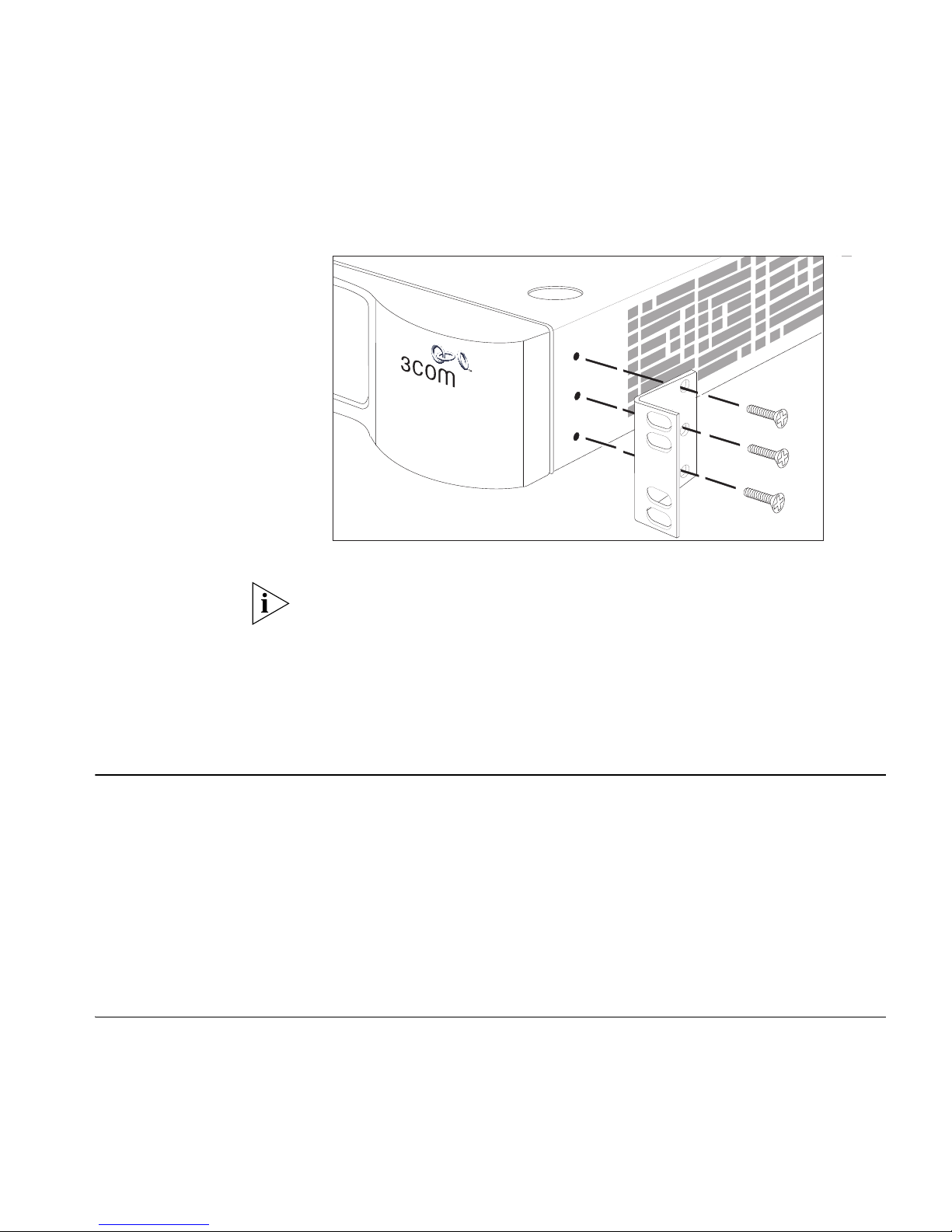
2 Locate a securing bracket over the mounting holes on one side of the
Switch, as shown in Figure 9
.
3 Insert the three screws and tighten with a suitable screwdriver.
24 CHAPTER 2: INSTALLING THE SWITCH
Figure 9 Fitting a bracket for rack-mounting
Placing Units On
Top of Each Other
Creating an XRN
Distributed Fabric
You must use the screws supplied with the securing brackets. Damage
caused to the unit by using incorrect screws invalidates your warranty.
4 Repeat steps 2 and 3 for the other side of the Switch.
5 Insert the Switch into the 19-inch rack and secure with suitable screws
(not provided). Ensure that ventilation holes are not obstructed.
6 Connect network cabling.
If the Switch units are free-standing, up to four units can be placed one
®
on top of the other. If you are mixing a variety of SuperStack
3 Switch
and Hub units, the smaller units must be positioned at the top.
If you are placing Switch units one on top of the other, you must use the
self-adhesive rubber pads supplied. Apply the pads to the underside of
each Switch, sticking one in the marked area at each corner. Place the
Switch units on top of each other, ensuring that the pads of the upper
unit line up with the recesses of the lower unit.
Switch 4900 Series units and 3Com Switch 4050/4060 units can be
interconnected to create an XRN Distributed Fabric and then treated as a
single manageable unit with one IP address. A combination of any two of
these units is allowed to be interconnected.
Creating an XRN Distributed Fabric 25
S/N: XXXX/7XXXXXXXXX
XRN Interconnect Module (3C17716)
Console
(max) 19200,8,1,N
Unit 1
Unit 2
Activity
Status
S/N: XXXX/7XXXXXXXXX
XRN Interconnect Module (3C17716)
Console
(max) 19200,8,1,N
Unit 1
Unit 2
Activity
Status
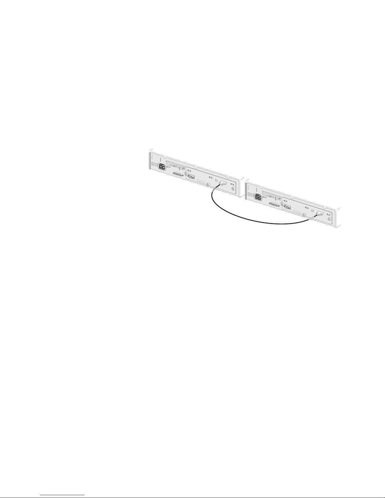
How To Interconnect
Units
To interconnect any two Switch 4900 Series or Switch 4050/4060 units
you will need to order the XRN Interconnect Module Kit (3C17715). The
kit consists of two XRN Interconnect Modules and an Interconnect Cable.
Both Switches must have an unused expansion slot to allow an
Interconnect Module to be fitted.
Figure 10 Interconnecting two Switch 4900 units
S
w
i
t
c
h
4
9
0
S
3
e
0
C
r
ia
1
7
l
N
70
o
0
X
M
X
X
A
/
C
X
A
X
X
d
X
d
X
r:
X
X
X
X
X
X
X
X
X
X
X
X
X
X
X
X
X
SUPPLY DATA
V-
90 - 240
Hz
A
5
0
/
6
0
4
.
I
5
I
R
N
E
F
P
E
U
R
T
T
O
M
I
N
A
S
N
T
V
R
U
U
A
C
L
T
F
I
O
O
A
R
N
C
M
O
2
R
a
7
R
x
E
C
T
1
2
Con
(m
sole
ax)
19200
,8,1,N
U
n
it 1
U
ni
A
t 2
S
/N
:
X
X
X
ct
X
/7
ivity
X
X
Sta
X
X
X
tu
X
s
X
X
X
X
RN Interconn
ect Module (3C17716)
S
w
i
t
c
h
4
9
0
S
3
e
0
C
r
i
1
a
7
l
N
7
0
o
0
X
M
X
X
A
/
C
X
X
A
X
d
X
d
X
r:
X
X
X
X
X
X
X
X
X
X
X
X
X
X
X
X
X
SUPPLY DATA
V-
90 - 240
Hz
A
5
0
/6
0
4
.
I
5
I
R
N
E
F
P
E
U
R
T
T
O
M
I
N
A
S
N
T
V
R
U
U
A
C
L
T
F
I
O
O
A
R
N
C
M
O
2
R
a
7
R
x
E
C
T
1
2
Console
(m
ax) 19200,8,1,N
U
n
it 1
U
n
A
it 2
S
/
N
:
X
X
X
ctiv
it
X
/
7
X
y
X
S
X
tatu
X
X
X
s
X
X
X
XRN Interconnect Module (3C17716
)
For information on ordering the XRN Interconnect Kits contact your
supplier. For illustrations and information on how to install the XRN
Interconnect Kits, refer to the user documentation that accompanies
these Kits.
Rules For
Interconnecting Units
This information is also provided in the user documentation that
accompanies the XRN Interconnect Kits.
■ The maximum number of Switch units that can be interconnected is
two.
■ XRN Interconnect Modules are NOT hot-swappable or hot-insertable.
Ensure that the Switch is powered off before inserting or removing an
Interconnect Module.
■ Only 3Com XRN Interconnect Cables can be used to connect two
Interconnect Modules.
■ It is not possible to interconnect the Switch 4900 Series and Switch
4050/4060 units with any other 3Com device.
■ 3Com strongly recommends that you upgrade all Switches to be
interconnected to the latest software agent.
■ 3Com recommends that you initialize a Switch unit that has previously
been used elsewhere in your network before you interconnect to an
 Loading...