

Page 1

SuperStack® 3
Switch Implementation Guide
Generic guide for units in the SuperStack 3 Switch 4200 Series:
3C17300, 3C17302
http://www.3com.com/
Part No. DUA1730-0 BAA01
Published April 2002
Page 2

3Com Corporation
5400 Bayfront Plaza
Santa Clara, California
95052-8145
Copyright © 2002, 3Com Technologies. All rights reserved. No part of this documentation may be reproduced
in any form or by any means or used to make any derivative work (such as translation, transformation, or
adaptation) without written permission from 3Com Technologies.
3Com Technologies reserves the right to revise this documentation and to make changes in content from time
to time without obligation on the part of 3Com Technologies to provide notification of such revision or
change.
3Com Technologies provides this documentation without warranty, term, or condition of any kind, either
implied or expressed, including, but not limited to, the implied warranties, terms or conditions of
merchantability, satisfactory quality, and fitness for a particular purpose. 3Com may make improvements or
changes in the product(s) and/or the program(s) described in this documentation at any time.
If there is any software on removable media described in this documentation, it is furnished under a license
agreement included with the product as a separate document, in the hard copy documentation, or on the
removable media in a directory file named LICENSE.TXT or !LICENSE.TXT. If you are unable to locate a copy,
please contact 3Com and a copy will be provided to you.
UNITED STATES GOVERNMENT LEGEND
If you are a United States government agency, then this documentation and the software described herein are
provided to you subject to the following:
All technical data and computer software are commercial in nature and developed solely at private expense.
Software is delivered as “Commercial Computer Software” as defined in DFARS 252.227-7014 (June 1995) or
as a “commercial item” as defined in FAR 2.101(a) an d as such is provided with only such rights as are
provided in 3Com’s standard commercial license for the Software. Technical data is provided with limited rights
only as provided in DFAR 252.227-7015 (Nov 1995) or FAR 52.227-14 (June 1987), whichever is applicable.
You agree not to remove or deface any portion of any legend provided on any licensed program or
documentation contained in, or delivered to you in conjunction with, this User Guide.
Unless otherwise indicated, 3Com registered trademarks are registered in the United States and may or may not
be registered in other countries.
3Com and SuperStack are registered trademarks of 3Com Corporation. The 3Com logo and CoreBuilder are
trademarks of 3Com Corporation.
Intel and Pentium are registered trademarks of Intel Corporation. Microsoft, MS-DOS, Windows, and Windows
NT are registered trademarks of Microsoft Corporation. Novell and NetWare are registered trademarks of
Novell, Inc. UNIX is a registered trademark in the United States and other countries, licensed exclusively
through X/Open Company, Ltd. Solaris is a registered trademark of Sun Microsystems.
All other company and product names may be trademarks of the respective companies with which they are
associated.
ENVIRONMENTAL STATEMENT
It is the policy of 3Com Corporation to be environmentally-friendly in all operations. To uphold our policy, we
are committed to:
Establishing environmental performance standards that comply with national legislation and regulations.
Conserving energy, materials and natural resources in all operations.
Reducing the waste generated by all operations. Ensuring that all waste conforms to recognized environmental
standards. Maximizing the recyclable and reusable content of all products.
Ensuring that all products can be recycled, reused and disposed of safely.
Ensuring that all products are labelled according to recognized environmental standards.
Improving our environmental record on a continual basis.
End of Life Statement
3Com processes allow for the recovery, reclamation and safe disposal of all end-of-life electronic components.
Regulated Materials Statement
3Com products do not contain any hazardous or ozone-depleting material.
Environmental Statement about the Documentation
The documentation for this product is printed on paper that comes from sustainable, managed forests; it is
fully biodegradable and recyclable, and is completely chlorine-free. The varnish is environmentally-friendly, and
the inks are vegetable-based with a low heavy-metal content.
Page 3

C
ONTENTS
BOUT THIS GUIDE
A
Conventions 8
Related Documentation 9
Documentation Comments 9
Product Registration 10
WITCH FEATURES OVERVIEW
1
S
What is Management Software? 13
Switch Features Explained 13
Automatic IP Configuration 14
Port Security 14
Aggregated Links 14
Auto-negotiation 14
Multicast Filtering 15
Spanning Tree Protocol and Rapid Spanning Tree Protocol 16
Switch Database 16
Traffic Prioritization 16
RMON 17
Broadcast Storm Control 17
VLANs 18
2
PTIMIZING BANDWIDTH
O
Port Features 19
Duplex 19
Flow Control 20
Auto-negotiation 20
Smart Auto-sensing 20
Aggregated Links 22
Aggregated Links and Your Switch 22
Aggregated Link Example 25
Page 4

3
SING MULTICAST FILTERING
U
What is an IP Multicast? 27
Benefits of Multicast 28
Multicast Filtering 28
Multicast Filtering and Your Switch 29
IGMP Multicast Filtering 30
4
5
SING RESILIENCE FEATURES
U
Spanning Tree Protocol (STP) 33
Rapid Spanning Tree Protocol (RSTP) 34
What is STP? 34
How STP Works 36
STP Requirements 36
STP Calculation 37
STP Configuration 38
STP Reconfiguration 38
How RSTP Differs to STP 38
STP Example 38
STP Configurations 40
Default Behavior 42
RSTP Default Behavior 42
Fast Start Default Behavior 42
Using STP on a Network with Multiple VLANs 42
SING THE SWITCH DATABASE
U
What is the Switch Database? 45
How Switch Database Entries Get Added 45
Switch Database Entry States 46
6
SING TRAFFIC PRIORITIZATION
U
What is Traffic Prioritization? 47
How Traffic Prioritization Works 48
802.1D traffic classification 48
DiffServ traffic classification 49
Traffic Prioritization and your Switch 50
Page 5

TATUS MONITORING AND STATISTICS
7
S
RMON 53
What is RMON? 53
The RMON Groups 54
Benefits of RMON 54
RMON and the Switch 55
Alarm Events 56
The Default Alarm Settings 56
The Audit Log 57
Email Notification of Events 57
Hardware Status Monitoring 58
ETTING UP VIRTUAL
8
S
What are VLANs? 61
Benefits of VLANs 62
VLANs and Your Switch 63
The Default VLAN 63
Creating New VLANs 63
VLANs: Tagged and Untagged Membership 64
Placing a Port in a Single VLAN 64
Connecting VLANS to Other VLANS 65
VLAN Configuration Examples 66
Using Untagged Connections 66
Using 802.1Q Tagged Connections 67
9
SING AUTOMATIC
U
How Your Switch Obtains IP Information 70
How Automatic IP Configuration Works 70
Automatic Process 71
Important Considerations 72
Server Support 72
Event Log Entries and Traps 72
IP C
S
LAN
ONFIGURATION
A
ONFIGURATION RULES
C
Configuration Rules for Gigabit Ethernet 75
Configuration Rules for Fast Ethernet 76
Page 6

Configuration Rules with Full Duplex 77
B
C
ETWORK CONFIGURATION EXAMPLES
N
Simple Network Configuration Examples 80
Segmentation Switch Example 80
Collapsed Backbone Switch Example 81
Desktop Switch Example 82
Advanced Network Configuration Examples 83
Improving the Resilience of Your Network 83
Enhancing the Performance of Your Network 84
DDRESSING
IP A
IP Addresses 85
Simple Overview 85
Advanced Overview 86
Subnets and Subnet Masks 88
Default Gateways 90
LOSSARY
G
NDEX
I
Page 7

A
BOUT
This guide describes the features of the SuperStack®3 Switch 4200 Series
and outlines how to use these features to optimize the performance of
your network.
This guide is intended for the system or network administrator who is
responsible for configuring, using, and managing the Switches. It
assumes a working knowledge of local area network (LAN) operations
and familiarity with communication protocols that are used to
interconnect LANs.
For detailed descriptions of the web interface operations and the
command line interface (CLI) commands that you require to manage the
Switch please refer to the Management Interface Reference Guide
supplied in HTML format on the CD-ROM that accompanies your Switch.
T
HIS
G
UIDE
If release notes are shipped with your product and the information there
differs from the information in this guide, follow the instructions in the
release notes.
Most user guides and release notes are available in Adobe Acrobat
Reader Portable Document Format (PDF) or HTML on the 3Com
World Wide Web site:
http://www.3com.com/
Page 8

A
8
BOUT THIS GUIDE
Conventions
Ta b l e 1 and Ta bl e 2 list conventions that are used throughout this guide.
Ta b l e 1
Icon Notice Type Description
Ta b l e 2
Convention Description
Screen displays
Syntax
Commands
The words “enter”
and “type”
Keyboard key names If you must press two or more keys simultaneously, the key
Words in
Notice Icons
Information note Information that describes important features or
instructions
Caution Information that alerts you to potential loss of data or
potential damage to an application, system, or device
Warning Information that alerts you to potential personal injury
Text Conventions
This typeface represents information as it appears on the
screen.
The word “syntax” means that you must evaluate the syntax
provided and then supply the appropriate values for the
placeholders that appear in angle brackets. Example:
To change your password, use the following syntax:
system password <password>
In this example, you must supply a password for <password>.
The word “command” means that you must enter the
command exactly as shown and then press Return or Enter.
Commands appear in bold. Example:
To display port information, enter the following command:
bridge port detail
When you see the word “enter” in this guide, you must type
something, and then press Return or Enter. Do not press
Return or Enter when an instruction simply says “type.”
names are linked with a plus sign (+). Example:
Press Ctrl+Alt+Del
italics
Italics are used to:
Emphasize a point.
■
Denote a new term at the place where it is defined in the
■
text.
Identify menu names, menu commands, and software
■
button names. Examples:
From the
menu, select
Help
Contents
.
Click OK.
Page 9

Related Documentation
9
Related
Documentation
In addition to this guide, each Switch documentation set includes the
following:
■
Getting Started Guide
This guide contains:
all the information you need to install and set up the Switch in its
■
default state
information on how to access the management software to begin
■
managing the Switch.
■
Management Interface Reference Guide
This guide contains information about the web interface operations
and CLI (command line interface) commands that enable you to
manage the Switch. It contains an explanation for each command and
the different parameters available. It is supplied in HTML format on
the CD-ROM that accompanies your Switch.
■
Management Quick Reference Guide
This guide contains:
A list of the features supported by the Switch
■
A summary of the web interface operations and CLI commands
■
that enable you to manage the Switch.
Documentation Comments
■
Release Notes
These notes provide information about the current software release,
including new features, modifications, and known problems.
In addition, there are other publications you may find useful:
Online documentation accompanying the 3Com Network Supervisor
■
application that is supplied on the CD-ROM that accompanies your
Switch.
Documentation accompanying the Advanced Redundant Power
■
System.
Your suggestions are very important to us. They will help make our
documentation more useful to you. Please e-mail comments about this
document to 3Com at:
pddtechpubs_comments@3com.com
Page 10

10
A
BOUT THIS GUIDE
Please include the following information when contacting us:
Document title
■
Document part number (on the title page)
■
Page number (if appropriate)
■
Example:
SuperStack 3 Switch Implementation Guide
■
Part number: DUA1730-0BAA0x
■
Page 25
■
Please note that we can only respond to comments and questions about
3Com product documentation at this e-mail address. Questions related to
technical support or sales should be directed in the first instance to your
network supplier.
Product Registration
You can now register your SuperStack 3 Switch on the 3Com web site:
http://support.3com.com/registration/frontpg.pl
Page 11

I
S
WITCH
Chapter 1 Switch Features Overview
F
EATURES
Chapter 2
Chapter 3
Chapter 4
Chapter 5
Chapter 6
Chapter 7
Chapter 8
Chapter 9
Optimizing Bandwidth
Using Multicast Filtering
Using Resilience Features
Using the Switch Database
Using Traffic Prioritization
Status Monitoring and Statistics
Setting Up Virtual LANs
Using Automatic IP Configuration
Page 12

12
Page 13

1
S
WITCH FEATURES
This chapter contains introductory information about the SuperStack®3
Switch management software and supported features. It covers the
following topics:
What is Management Software?
■
Switch Features Explained
■
For detailed descriptions of the web interface operations and the
command line interface (CLI) commands that you require to manage the
Switch please refer to the Management Interface Reference Guide
supplied in HTML format on the CD-ROM that accompanies your Switch.
O
VERVIEW
What is
Management
Software?
Switch Features
Explained
Your Switch can operate in its default state. However, to make full use of
the features offered by the Switch, and to change and monitor the way it
works, you have to access the management software that resides on the
Switch. This is known as managing the Switch.
Managing the Switch can help you to improve its efficiency and therefore
the overall performance of your network.
There are several different methods of accessing the management
software to manage the Switch. These methods are explained in
Chapter 3 of the Getting Started Guide that accompanies your Switch.
The management software provides you with the capability to change the
default state of some of the Switch features. This section provides a brief
overview of these features — their applications are explained in more
detail later in this guide.
For a list of the features supported by your Switch, please refer to the
Management Quick Reference Guide that accompanies your Switch.
Page 14

14
C
HAPTER
1: S
WITCH FEATURES OVERVIEW
Automatic IP
Configuration
Port Security
By default the Switch tries to configure itself with IP information without
requesting user intervention. It uses the following industry standard
methods to allocate the Switch IP information:
Dynamic Host Configuration Protocol (DHCP)
■
Auto-IP — the Switch will configure itself with its default IP address
■
169.254.100.100 if it is operating in a standalone mode, and/or no
other Switches on the network have this IP address. If this default
IP address is already in use on the network then the Switch detects
this and configures itself with an IP address in the range
169.254.1.0 to 169.254.254.255.
Bootstrap Protocol (BOOTP)
■
For ease of use, you do not have to choose between these three
automatic configuration methods. The Switch tries each method in a
specified order.
For more information about how the automatic IP configuration feature
works, see
Chapter 9
“Using Automatic IP Configuration”
.
Port security guards against unauthorized users connecting devices to
your network. The port security feature, Disconnect Unauthorised Device
(DUD), disables a port if an unauthorised device transmits data on it.
Aggregated Links
Auto-negotiation
Aggregated links are connections that allow devices to communicate
using up to two links in parallel. On the Switch 4200, aggregated links
are only supported on the 10/100/1000 Mbps ports. Aggregated links
provide two benefits:
They can potentially double the bandwidth of a connection.
■
They can provide redundancy — if one link is broken, the other link
■
can share the traffic for that link.
For more information about aggregated links, see
“Optimizing Bandwidth”
.
Chapter 2
Auto-negotiation allows ports to auto-negotiate port speed,
duplex-mode (only at 10 Mbps and 100 Mbps) and flow control. When
auto-negotiation is enabled (default), a port “advertises” its maximum
capabilities — these capabilities are by default the parameters that
provide the highest performance supported by the port.
Page 15
Switch Features Explained
15
For details of the auto-negotiation features supported by your Switch,
please refer to the Getting Started Guide that accompanies your Switch.
Ports operating at 1000 Mbps only support full duplex mode.
Duplex
Full duplex mode allows packets to be transmitted and received
simultaneously and, in effect, doubles the potential throughput of a link.
Flow Control
All Switch ports support flow control, which is a mechanism that
minimizes packet loss during periods of congestion on the network.
Flow control is supported on ports operating in half duplex mode, and is
implemented using the IEEE 802.3x standard on ports operating in full
duplex mode.
Smart Auto-sensing
Smart auto-sensing allows auto-negotiating multi-speed ports, such as
10/100 Mbps or 10/100/1000 Mbps, to monitor and detect high error
rates, or problems in the “physical” interconnection to another port. The
port reacts accordingly by tuning the link from its higher speed to the
lower supported speed to provide an error-free connection to the
network.
Multicast Filtering
For more information about auto-negotiation and port capabilities, see
Chapter 2
“Optimizing Bandwidth”
.
Multicast filtering allows the Switch to forward multicast traffic to only
the endstations that are part of a predefined multicast group, rather than
broadcasting the traffic to the whole network.
The multicast filtering system supported by your Switch uses IGMP
(Internet Group Management Protocol) snooping to detect the
endstations in each multicast group to which multicast traffic should be
forwarded.
For more information about multicast filtering, see
Multicast Filtering”
.
Chapter 3
“Using
Page 16

16
C
HAPTER
1: S
WITCH FEATURES OVERVIEW
Spanning Tree
Protocol and Rapid
Spanning Tree
Protocol
Switch Database
Spanning Tree Protocol (STP) and Rapid Spanning Tree Protocol (RSTP)
are bridge-based systems that makes your network more resilient to
link failure and also provides protection from network loops — one of
the major causes of broadcast storms.
STP allows you to implement alternative paths for network traffic in the
event of path failure and uses a loop-detection process to:
Discover the efficiency of each path.
■
Enable the most efficient path.
■
Disable the less efficient paths.
■
Enable one of the less efficient paths if the most efficient path fails.
■
RSTP is an enhanced version of the STP feature and is enabled by default.
RSTP can restore a network connection quicker than the STP feature.
STP conforms to the IEEE 802.1D-1998 standard, and RSTP conforms to
the IEEE 802.1w standard.
For more information about STP and RSTP, see
Resilience Features”
.
Chapter 4
“Using
The Switch Database is an integral part of the Switch and is used by the
Switch to determine if a packet should be forwarded, and which port
should transmit the packet if it is to be forwarded.
Traffic Prioritization
For more information about the Switch Database, see
the Switch Database”
.
Chapter 5
“Using
Traffic prioritization allows your network traffic to be prioritized to ensure
that high priority data, such as time-sensitive and system-critical data is
transferred smoothly and with minimal delay over a network.
Traffic prioritization ensures that high priority data is forwarded through
the Switch without being delayed by lower priority data. Traffic
prioritization uses the two traffic queues that are present in the hardware
of the Switch to ensure that high priority traffic is forwarded on a
different queue from lower priority traffic. High priority traffic is given
preference over low priority traffic to ensure that the most critical traffic
gets the highest level of service.
Page 17

Switch Features Explained
This system is compatible with the relevant sections of the IEEE
802.1D/D17 standard (incorporating IEEE 802.1p).
17
RMON
For more information about 802.1D and traffic prioritization, see
6 “Using Traffic Prioritization”
.
Chapter
Quality of Service
Traffic prioritization can be taken one step further by using the Quality of
Service (QoS) feature. Quality of Service (QoS) enables you to specify
service levels for different traffic classifications. This enables you to
prioritize particular applications or traffic types.
The Switch uses a policy-based QoS mechanism. By default, all traffic is
assigned the "normal" QoS policy profile. If needed, you can create other
QoS policy profiles and apply them to different traffic types so that they
have different priorities across the network.
For more information about Quality of Service, see
Traffic Prioritization”
.
Chapter 6
“Using
Remote Monitoring (RMON) is an industry standard feature for traffic
monitoring and collecting network statistics. The Switch software
continually collects statistics about the LAN segments connected to the
Switch. If you have a management workstation with an RMON
management application, the Switch can transfer these statistics to your
workstation on request or when a pre-defined threshold is exceeded.
Broadcast Storm
Control
Event Notification
You can configure your Switch to send you notification when certain
events occur. You can receive notification via email, SMS (Short Message
Server), or pager.
For more information about RMON and Event Notification, see
“Status Monitoring and Statistics”
.
Chapter 7
Broadcast Storm Control is a system that monitors the level of broadcast
traffic on that port.
number of frames per
is blocked until the broadcast
If the broadcast traffic level rises to a pre-defined
second (threshold), the broadcast traffic on the port
traffic level drops below the threshold.
This
system prevents the overwhelming broadcast traffic that can result from
network equipment which is faulty or configured incorrectly.
Page 18

18
C
HAPTER
1: S
WITCH FEATURES OVERVIEW
VLANs
A Virtual LAN (VLAN) is a flexible group of devices that can be located
anywhere in a network, but which communicate as if they are on the
same physical segment. With VLANs, you can segment your network
without being restricted by physical connections — a limitation of
traditional network design. As an example, with VLANs you can segment
your network according to:
Departmental groups
■
Hierarchical groups
■
Usage groups
■
For more information about VLANs, see
LANs”
.
Chapter 8
“Setting Up Virtual
Page 19

2
O
PTIMIZING
There are many ways you can optimize the bandwidth on your network
and improve network performance. If you utilize certain Switch features
you can provide the following benefits to your network and end users:
Increased bandwidth
■
Quicker connections
■
Faster transfer of data
■
Minimized data errors
■
Reduced network downtime
■
For detailed descriptions of the web interface operations and the
command line interface (CLI) commands that you require to manage the
Switch please refer to the Management Interface Reference Guide
supplied in HTML format on the CD-ROM that accompanies your Switch.
B
ANDWIDTH
Port Features
Duplex
The default state for all the features detailed below provides the best
configuration for a typical user.
alter the Switch from its default state.
you may wish to alter the default state of these ports, for example, if you
want to force a port to operate at 10 Mbps.
Full duplex allows packets to be transmitted and received simultaneously
and, in effect, doubles the potential throughput of a link. Half duplex
only allows packets to be transmitted or received at any one time.
To communicate effectively, both devices at either end of a link
the same duplex mode. If the devices at either end of a link support
auto-negotiation, this is done automatically.
In normal operation, you do not need to
However, under certain conditions
use
must
Page 20

20
C
HAPTER
2: O
PTIMIZING BANDWIDTH
If the devices at either end of a link do not support auto-negotiation,
both ends must be manually set to full duplex or half duplex accordingly.
Ports operating at 1000 Mbps support full duplex mode only.
Flow Control
Auto-negotiation
All Switch ports support flow control, which is a mechanism that
minimizes packet loss during periods of congestion on the network.
Packet loss is caused by one or more devices sending traffic to an already
overloaded port on the Switch. Flow control minimizes packet loss by
inhibiting the transmitting port from generating more packets until the
period of congestion ends.
Flow control is supported on ports operating in half duplex mode, and is
implemented using the IEEE 802.3x standard on ports operating in full
duplex mode.
Auto-negotiation allows ports to auto-negotiate port speed,
duplex-mode (only at 10 Mbps and 100 Mbps) and flow control. When
auto-negotiation is enabled (default), a port “advertises” its maximum
capabilities — these capabilities are by default the parameters that
provide the highest performance supported by the port.
You can disable auto-negotiation on all fixed ports on the Switch, or on a
per port basis. You can also modify the capabilities that a port
“advertises” on a per port basis, dependent on the type of port.
For auto-negotiation to work, ports at both ends of the link must be set
to auto-negotiate.
Smart Auto-sensing
Ports operating at 1000 Mbps support full duplex mode only.
If auto-negotiation is disabled, the ports will no longer operate in
auto-MDIX mode. Therefore, if you wish to disable auto-negotiation you
must ensure you have the correct type of cable, that is cross-over or
straight-through, for the type of device you are connecting to. For more
information on suitable cable types, please refer to the Getting Started
Guide that accompanies your Switch.
Smart auto-sensing allows auto-negotiating multi-speed ports, such as
10/100 Mbps or 10/100/1000 Mbps, to monitor and detect a high error
rate on a link, or a problem in the “physical” interconnection to another
Page 21

Port Features
21
port and react accordingly. In other words, auto-negotiation may “agree”
upon a configuration that the cable cannot sustain; smart auto-sensing
can detect this and adjust the link accordingly.
For example, smart auto-sensing can detect network problems, such as
an unacceptably high error rate or a poor quality cable. If both ends of
the link support 100/1000 Mbps auto-negotiation, then auto-sensing
tunes the link to 100 Mbps to provide an error-free 100 Mbps connection
to the network.
An SNMP Trap is sent every time a port is down-rated to a lower speed.
Conditions that affect smart auto-sensing:
Smart auto-sensing will not operate on links that do not support
■
auto-negotiation, or on links where one end is at a fixed speed. The
link will reset to the higher speed of operation when the link is lost or
the unit is power cycled.
Smart auto-sensing can only be configured per unit and not on a per
■
port basis.
Page 22
22
C
HAPTER
2: O
PTIMIZING BANDWIDTH
Aggregated Links
Aggregated links are connections that allow devices to communicate
using up to two links in parallel. Aggregated links are supported on the
10/100/1000BASE-T ports only
They can potentially double the bandwidth of a connection.
■
They can provide redundancy — if one link is broken, the other link
■
.
These parallel links provide two benefits:
can share the traffic for that link.
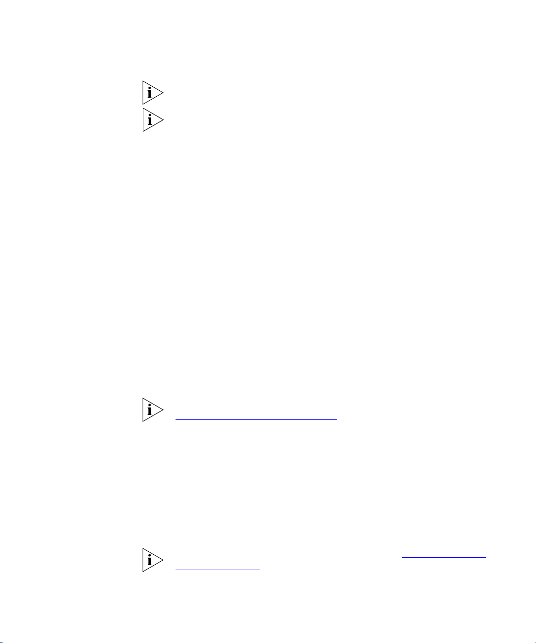
Figure 1
shows two Switches connected using an aggregated link
containing two member links. If the ports on both Switch units are
configured as 1000BASE-T and they are operating in full duplex, the
potential maximum bandwidth of the connection is 2 Gbps.
Figure 1
.
Switch units connected using an aggregated link
Switch
Aggregated Link
Switch
Aggregated Links and
Your S w i tch
Each Switch supports up to two aggregated links. Each aggregated link
can support up to two member links.
When setting up an aggregated link, note that:
The ports at both ends of a member link must be configured as
■
members of an aggregated link.
A member link port can only belong to one aggregated link.
■
The member link ports can have different port configurations within
■
the same aggregated link, that is, auto-negotiation, port speed, and
duplex mode. However, please note the following:
To be an active participant in an aggregated link the member link
■
ports must operate in full duplex mode. (If a member link port does
not operate in full duplex mode it can still be a member of an
aggregated link but it will never be activated.)
Page 23
Aggregated Links
If ports of a different speed are aggregated together, the higher
■
speed links carry the traffic. The lower speed links only carry the
traffic if the higher speed links fail.
The aggregated link does not support security.
■
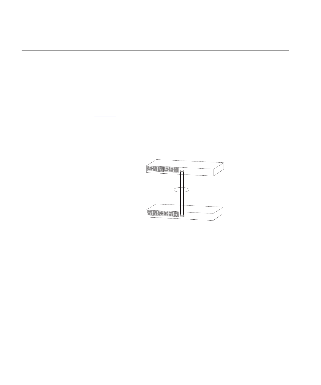
Member links must retain the same groupings at both ends of an
■
aggregated link. For example, the configuration in Figure 2
will not
work as Switch A has one aggregated link defined whose member
links are then split between two aggregated links defined on Switches
B and C.
23
Figure 2
An illegal aggregated link configuration
Switch A
AL 1
Switch B
AL 2
Switch C
AL 3
When using an aggregated link, note that:
To gather statistics about an aggregated link, you must add together
■
the statistics for each port in the aggregated link.
If you wish to disable a single member link of an aggregated link, you
■
must first physically remove the connection to ensure that you do not
lose any traffic, before you disable both ends of the member link
separately. If you do this, the traffic destined for that link is distributed
to the other links in the aggregated link.
If you do not remove the connection and only disable one end of the
member link port, traffic is still forwarded to that port by the
aggregated link port at the other end. This means that a significant
amount of traffic may be lost.
Before removing all member links from an aggregated link, you must
■
disable all the aggregated link member ports or disconnect all the
links, except one — if you do not, a loop may be created.
Page 24

24
C
HAPTER
2: O
PTIMIZING BANDWIDTH
Traffic Distribution and Link Failure on Aggregated Links
To maximize throughput, all traffic is distributed across the individual links
that make up an aggregated link. Therefore, when a packet is made
available for transmission down an aggregated link, a hardware-based
traffic distribution mechanism determines which particular port in the link
should be used; this mechanism uses the MAC address. The traffic is
distributed among the member links as efficiently as possible.
To avoid the potential problem of out-of-sequence packets (or “packet
re-ordering”), the Switch ensures that all the conversations between a
given pair of endstations will pass through the same port in the
aggregated link. Single-to-multiple endstation conversations, on the
other hand, may still take place over different ports.
If the link state on any of the ports in an aggregated link becomes
inactive due to link failure, then the Switch will automatically redirect the
aggregated link traffic to the remaining ports. Aggregated links therefore
provide built-in resilience for your network.
The Switch also has a mechanism to prevent the possible occurrence of
packet re-ordering when a link recovers too soon after a failure.
Page 25
Aggregated Links
k
25
Aggregated Link
Example
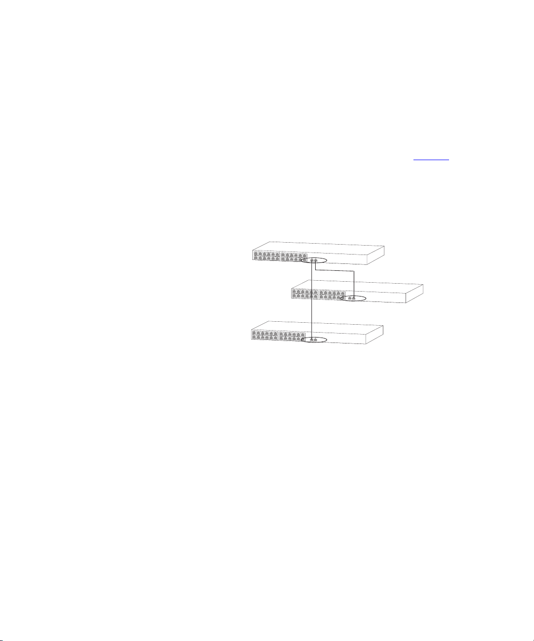
The example shown in Figure 3
illustrates an 2 Gbps aggregated link
between two Switch units.
Figure 3
A 2 Gbps aggregated link between two Switch units
Switch
2 G bps Aggregated Lin
Switch
To set up this configuration:
Add the 1000BASE-T ports on the upper unit to the aggregated link.
1
Add the 1000BASE-T ports on the lower unit to the aggregated link.
2
Connect the 1000BASE-T port marked ‘Up’ on the upper Switch to the
3
1000BASE-T port marked ‘Up’ on the lower Switch.
Connect the 1000BASE-T port marked ‘Down’ on the upper Switch to
4
the 1000BASE-T port marked ‘Down’ on the lower Switch.
Page 26

26
C
HAPTER
2: O
PTIMIZING BANDWIDTH
Page 27

3
U
SING
Multicast filtering improves the performance of networks that carry
multicast traffic.
This chapter explains multicasts, multicast filtering, and how multicast
filtering can be implemented on your Switch. It covers the following
topics:
What is an IP Multicast?
■
Multicast Filtering
■
IGMP Multicast Filtering
■
For detailed descriptions of the web interface operations and the
command line interface (CLI) commands that you require to manage the
Switch please refer to the Management Interface Reference Guide
supplied in HTML format on the CD-ROM that accompanies your Switch.
M
ULTICAST FILTERING
What is an IP
Multicast?
A
multicast
to-many” communication. Users explicitly request to participate in the
communication by joining an endstation to a specific multicast group. If
the network is set up correctly, a multicast can only be sent to an
endstation or a subset of endstations in a LAN, or VLAN, that belong to
the relevant multicast group.
Multicast group members can be distributed across multiple
subnetworks; thus, multicast transmissions can occur within a campus
LAN or over a WAN. In addition, networks that support IP multicast send
only
delivery path that reaches group members diverges. It is only at these
points that multicast packets are replicated and forwarded, which makes
efficient use of network bandwidth.
is a packet that is intended for “one-to-many” and “many-
copy of the desired information across the network until the
one
Page 28

28
C
HAPTER
3: U
SING MULTICAST FILTERING
A multicast packet is identified by the presence of a multicast group
address in the destination address field of the packet’s IP header.
Benefits of Multicast
Multicast Filtering
The benefits of using IP multicast are that it:
Enables the simultaneous delivery of information to many receivers in
■
the most efficient, logical way.
Reduces the load on the source (for example, a server) because it does
■
not have to produce multiple copies of the same data.
Makes efficient use of network bandwidth and scales well as the
■
number of participants or collaborators expands.
Works with other IP protocols and services, such as Quality of Service
■
(QoS).
There are situations where a multicast approach is more logical and
efficient than a unicast approach. Application examples include distance
learning, transmitting stock quotes to brokers, and collaborative
computing.
A typical use of multicasts is in video-conferencing, where high volumes
of traffic need to be sent to several endstations simultaneously, but where
broadcasting that traffic to all endstations would seriously reduce
network performance.
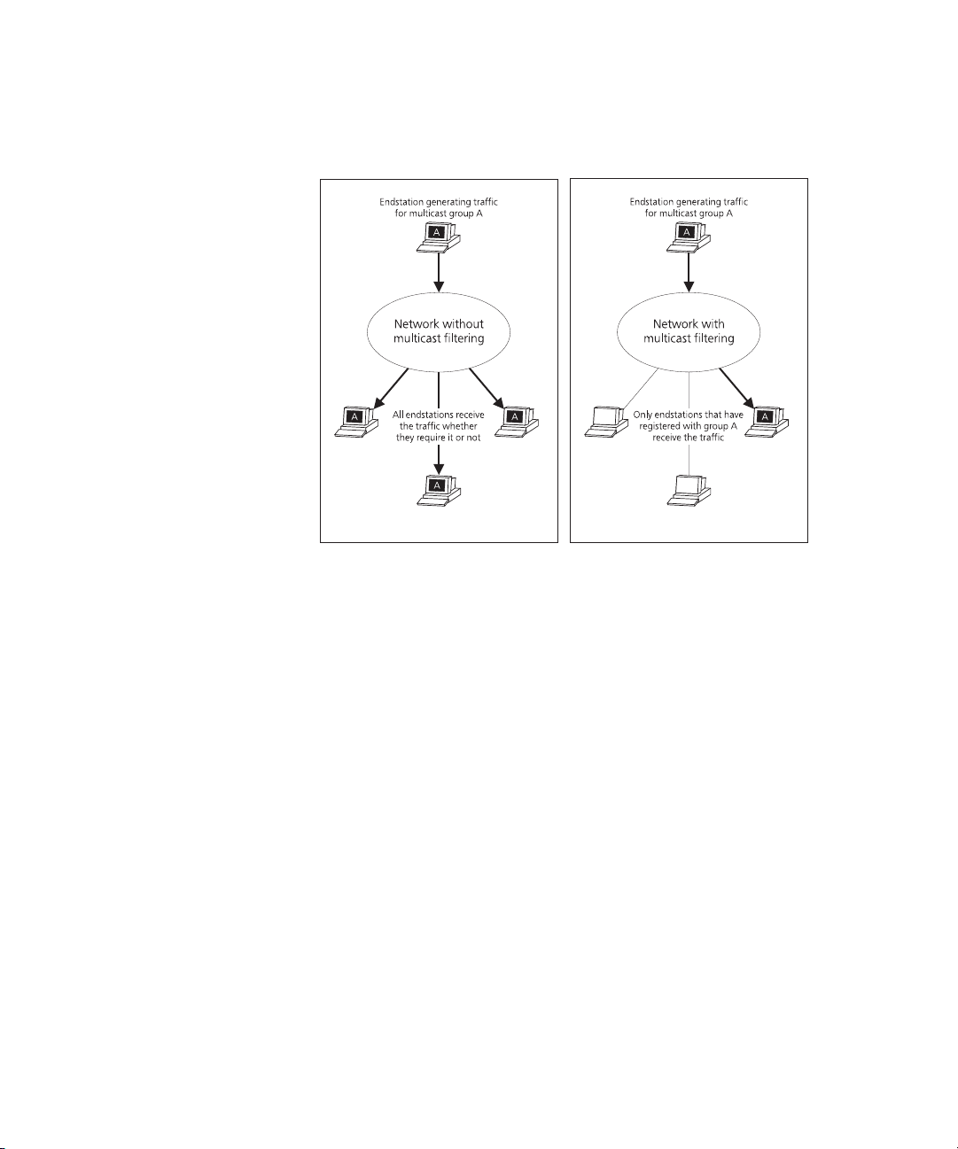
Multicast filtering is the process that ensures that endstations only receive
multicast traffic if they register to join specific multicast groups. With
multicast filtering, network devices only forward multicast traffic to the
ports that are connected to registered endstations.
Figure 4
shows how a network behaves without multicast filtering and
with multicast filtering.
Page 29
Multicast Filtering
29
Multicast Filtering
and Your Switch
Figure 4
The effect of multicast filtering
Your Switch provides automatic multicast filtering support using IGMP
(Internet Group Management Protocol) Snooping. It also supports IGMP
query mode.
Snooping Mode
Snooping Mode allows your Switch to forward multicast packets only to
the appropriate ports. The Switch “snoops” on exchanges between
endstations and an IGMP device, typically a router, to find out the ports
that wish to join a multicast group and then sets its filters accordingly
Query Mode
Query mode allows the Switch to function as the Querier if it has the
lowest IP address in the subnetwork to which it belongs.
IGMP querying is disabled by default on the Switch 4200. This helps
prevent interoperability issues with core products that may not follow the
lowest IP address election method.
You can enable or disable IGMP query mode for all Switch units in the
stack using the
queryMode
command on the command line interface
IGMP menu.
You would enable query mode if you wish to run multicast sessions in a
network that does not contain any IGMP routers (or queriers). This
Page 30

30
C
HAPTER
3: U
SING MULTICAST FILTERING
command will configure the Switch 4200 Series to automatically
negotiate with compatible devices on VLAN 1 to become the querier.
The Switch 4200 Series is compatible with any device that conforms to
the IGMP v2 protocol.
IGMP Multicast Filtering
IGMP is the system that all IP-supporting network devices use to register
endstations with multicast groups. It can be used on all LANs and VLANs
that contain a multicast capable IP router and on other network devices
that support IP.
IGMP multicast filtering works as follows:
The IP router (or querier) periodically sends
1
packets to all the
query
endstations in the LANs or VLANs that are connected to it.
If your network has more than one IP router, then the one with the lowest
IP address becomes the querier. The Switch can be the IGMP querier and
will become so if its own IP address is lower than that of any other IGMP
queriers connected to the LAN or VLAN. However, as the Switch only has
an IP address on its default VLAN, the Switch will only ever query on the
default VLAN (VLAN1). Therefore, if there are no other queriers on other
VLANs, the IP multicast traffic will not be forwarded on them.
When an IP endstation receives a query packet, it sends a
2
report
packet
back that identifies the multicast group that the endstation would like to
join.
When the report packet arrives at a port on a Switch with
3
learning
enabled, the Switch learns that the port is to forward traffic for
IGMP multicast
the multicast group and then forwards the packet to the router.
When the router receives the report packet, it registers that the LAN or
4
VLAN requires traffic for the multicast groups.
When the router forwards traffic for the multicast group to the LAN or
5
VLAN, the Switch units only forward the traffic to ports that received a
report packet.
Enabling IGMP Multicast Learning
You can enable or disable multicast learning and IGMP querying using the
snoopMode
command on the CLI or the web interface. For more
information about enabling IGMP multicast learning, please refer to the
Management Interface Reference Guide supplied on your Switch
CD-ROM.
Page 31

IGMP Multicast Filtering
31
If IGMP multicast learning is not enabled then IP multicast traffic is always
forwarded, that is, it floods the network.
For information about configuring IGMP functionality on an endstation,
refer to the user documentation supplied with your endstation or the
endstation’s Network Interface Card (NIC).
Page 32

32
C
HAPTER
3: U
SING MULTICAST FILTERING
Page 33

4
U
SING
Setting up resilience on your network helps protect critical links against
failure, protects against network loops, and reduces network downtime
to a minimum.
This chapter explains the features supported by the Switch that provide
resilience for your network. It covers the following topics:
Spanning Tree Protocol (STP)
■
Rapid Spanning Tree Protocol (RSTP) — an enhanced STP feature.
■
For detailed descriptions of the web interface operations and the
command line interface (CLI) commands that you require to manage the
Switch please refer to the Management Interface Reference Guide
supplied in HTML format on the CD-ROM that accompanies your Switch.
R
ESILIENCE FEATURES
Spanning Tree
Protocol (STP)
The Spanning Tree Protocol (STP) makes your network more resilient to
link failure and also provides a protection from loops — one of the major
causes of broadcast storms. STP is enabled by default on your Switch.
To be fully effective, STP must be enabled on all Switches in your
network.
The following sections explain more about STP and the protocol features
supported by your Switch. They cover the following topics:
What is STP?
■
How STP Works
■
Using STP on a Network with Multiple VLANs
■
The protocol is a part of the IEEE 802.1D bridge specification. To explain
STP more effectively, your Switch will be referred to as a bridge.
Page 34

34
C
HAPTER
4: U
SING RESILIENCE FEATURES
Rapid Spanning Tree
Protocol (RSTP)
The Rapid Spanning Tree (RSTP) is an enhanced Spanning Tree feature.
RSTP implements the Spanning Tree Algorithm and Protocol, as defined in
the IEEE 802.1w standard.
3Com recommends that you use the Rapid Spanning Tree Protocol
feature (enabled by default) to provide optimum performance for your
network and ease of use.
Some of the benefits of RSTP are:
Faster determination of the Active Spanning Tree topology throughout
■
a bridged network.
Support for bridges with more than 256 ports.
■
Standard support for the Fast-Forwarding configuration of edge ports.
■
This is currently supported by the 'Fast Start' implementation.
Easy deployment throughout a legacy network, through backward
■
compatibility:
it will default to sending 802.1D style BPDU's on a port if it receives
■
packets of this format.
it is possible for some ports on a Switch to operate in RSTP
■
(802.1w) mode, and other ports, for example those connected to a
legacy Switch, to operate in STP (802.1D) mode.
What is STP?
you have an option to force your Switch to use the legacy 802.1D
■
version of Spanning Tree, if required.
STP is a bridge-based system that allows you to implement parallel paths
for network traffic and uses a loop-detection process to:
Find and disable the less efficient paths (that is, the paths that have a
■
lower bandwidth).
Enable one of the less efficient paths if the most efficient path fails.
■
RSTP provides the same functionality as STP. For details on how the two
systems differ, see “How RSTP Differs to STP”
As an example, Figure 5
shows a network containing three LAN segments
on page 38.
separated by three bridges. With this configuration, each segment can
communicate with the others using two paths. Without STP enabled, this
configuration creates loops that cause the network to overload.
Page 35

What is STP?
35
Figure 5
A network configuration that creates loops
Figure 6 shows the result of enabling STP on the bridges in the
configuration. STP detects the duplicate paths and prevents, or
blocks
,
one of them from forwarding traffic, so this configuration will work
satisfactorily. STP has determined that traffic from LAN segment 2 to LAN
segment 1 can only flow through Bridges C and A, because, for example,
this path has a greater bandwidth and is therefore more efficient.
Figure 6
Traffic flowing through Bridges C and A
If a link failure is detected, as shown in Figure 7, the STP process
reconfigures the network so that traffic from LAN segment 2 flows
through Bridge B.
Page 36

36
C
HAPTER
4: U
SING RESILIENCE FEATURES
Figure 7
Traffic flowing through Bridge B
STP determines which is the most efficient path between each bridged
segment and a specifically assigned reference point on the network. Once
the most efficient path has been determined, all other paths are blocked.
Therefore, in Figure 5, Figure 6, and Figure 7, STP initially determined that
the path through Bridge C was the most efficient, and so blocked the
path through Bridge B. After the failure of Bridge C, STP re-evaluated the
situation and opened the path through Bridge B.
How STP Works
STP Requirements
When enabled, STP determines the most appropriate path for traffic
through a network. It does this as outlined in the sections below.
Before it can configure the network, the STP system requires:
Communication between all the bridges. This communication is
■
carried out using Bridge Protocol Data Units (BPDUs), which are
transmitted in packets with a known multicast address.
Each bridge to have a Bridge Identifier. This specifies which bridge acts
■
as the central reference point, or Root Bridge, for the STP system —
the lower the Bridge Identifier, the more likely the bridge is to become
the Root Bridge. The Bridge Identifier is calculated using the MAC
address of the bridge and a priority defined for the bridge. The default
priority of your Switch is 32768.
Each port to have a cost. This specifies the efficiency of each link,
■
usually determined by the bandwidth of the link — the higher the
Page 37

How STP Works
cost, the less efficient the link. Table 3 shows the default port costs for
a Switch.
Ta b l e 3
Default port costs
37
STP Calculation
Port Speed Link Type
10 Mbps Half Duplex
Full Duplex
Aggregated Link
100 Mbps Half Duplex
Full Duplex
Aggregated Link
1000 Mbps Full Duplex
Aggregated Link
* This path cost is correct where there are two ports in an aggregated link. However, if there are
more ports in the aggregated link, the path cost will be proportionately lower. For example, if
there are four ports in the aggregated link, the 802.1w path costs will be: 500,000 for
10 Mbps, 50,000 for 100 Mbps, and 5,000 for 1000 Mbps. The 802.1D-1998 path cost values
are not affected by the number of ports in an aggregated link.
Path Cost
802.1D-1998
100
95
90
19
18
15
4
3
Path Cost
802.1w
2,000,000
1,999,999
1,000,000
200,000
199,999
100,000*
20,000
10,000*
*
The first stage in the STP process is the calculation stage. During this
stage, each bridge on the network transmits BPDUs that allow the system
to work out:
The identity of the bridge that is to be the Root Bridge. The Root
■
Bridge is the central reference point from which the network is
configured.
The Root Path Costs for each bridge — that is, the cost of the paths
■
from each bridge to the Root Bridge.
The identity of the port on each bridge that is to be the Root Port.
■
The Root Port is the one that is connected to the Root Bridge using
the most efficient path, that is, the one that has the lowest Root
Path Cost. Note that the Root Bridge does not have a Root Port.
The identity of the bridge that is to be the Designated Bridge of
■
each LAN segment. The Designated Bridge is the one that has the
lowest Root Path Cost from that segment. Note that if several
bridges have the same Root Path Cost, the one with the lowest
Bridge Identifier becomes the Designated Bridge.
All traffic destined to pass in the direction of the Root Bridge flows
through the Designated Bridge. The port on this bridge that connects
to the segment is called the Designated Bridge Port.
Page 38

38
C
HAPTER
4: U
SING RESILIENCE FEATURES
STP Configuration
STP Reconfiguration
How RSTP Differs to
STP
After all the bridges on the network have agreed on the identity of the
Root Bridge, and have established the other relevant parameters, each
bridge is configured to forward traffic only between its Root Port and the
Designated Bridge Ports for the respective network segments. All other
ports are blocked, which means that they are prevented from receiving or
forwarding traffic.
Once the network topology is stable, all the bridges listen for Hello BPDUs
transmitted from the Root Bridge at regular intervals. If a bridge does not
receive a Hello BPDU after a certain interval (the Max Age time), the
bridge assumes that the Root Bridge, or a link between itself and the
Root Bridge, has gone down. The bridge then reconfigures the network
to cater for the change. If you have configured an SNMP trap destination,
when the topology of your network changes, the first bridge to detect
the change sends out an SNMP trap.
CAUTION:
Network loops can occur if aggregated links are manually
configured incorrectly, that is, the physical connections do not match the
assignment of ports to an aggregated link. RSTP and STP may not detect
these loops. So that RSTP and STP can detect all network loops you must
ensure that all aggregated links are configured correctly.
RSTP works in a similar way to STP, but it includes additional information
in the BPDUs. This information allows each bridge to confirm that it has
taken action to prevent loops from forming when it wants to enable a
link to a neighbouring bridge. This allows adjacent bridges connected via
point-to-point links to enable a link without having to wait to ensure all
other bridges in the network have had time to react to the change.
STP Example
So the main benefit of RSTP is that the configuration decision is made
locally rather than network-wide which is why RSTP can carry out
automatic configuration and restore a link faster than STP.
Figure 8 shows a LAN that has STP enabled. The LAN has three segments,
and each segment is connected using two possible links.
Page 39

How STP Works
39
Figure 8
Port costs in a network
Bridge A has the lowest Bridge Identifier in the network, and has
■
therefore been selected as the Root Bridge.
Because Bridge A is the Root Bridge, it is also the Designated Bridge
■
for LAN segment 1. Port 1 on Bridge A is therefore selected as the
Designated Bridge Port for LAN Segment 1.
Port 1 of Bridges B, C, X and Y have been defined as Root Ports
■
because they are the nearest to the Root Bridge and therefore have
the most efficient path.
Bridges B and X offer the same Root Path Cost for LAN segment 2,
■
however, Bridge B has been selected as the Designated Bridge for the
segment because it has a lower Bridge Identifier. Port 2 on Bridge B is
therefore selected as the Designated Bridge Port for LAN Segment 2.
Page 40

40
C
HAPTER
4: U
SING RESILIENCE FEATURES
■
Bridge C has been selected as the Designated Bridge for LAN segment
3, because it offers the lowest Root Path Cost for LAN Segment 3:
the route through Bridges C and B costs 200 (C to B=100, B to
■
A=100)
the route through Bridges Y and B costs 300 (Y to B=200, B to
■
A=100).
Port 2 on Bridge C is therefore selected as the Designated Bridge Port
for LAN Segment 3.
STP Configurations
Figure 9 shows three possible STP configurations using SuperStack 3
Switch units.
■
Configuration 1 — Redundancy for Backbone Link
In this configuration, the Switches both have STP enabled and are
connected by two links. STP discovers a duplicate path and blocks one
of the links. If the enabled link breaks, the disabled link becomes
re-enabled, therefore maintaining connectivity.
■
Configuration 2 — Redundancy through Meshed Backbone
In this configuration, four Switch units are connected in a way that
creates multiple paths between each one. STP discovers the duplicate
paths and blocks two of the links. If an enabled link breaks, one of the
disabled links becomes re-enabled, therefore maintaining connectivity.
■
Configuration 3 — Redundancy for Cabling Error
In this configuration, a Switch has STP enabled and is accidentally
connected to a hub using two links. STP discovers a duplicate path
and blocks one of the links, therefore avoiding a loop.
Page 41

How STP Works
41
Figure 9
STP configurations
Page 42

42
C
HAPTER
4: U
SING RESILIENCE FEATURES
Default Behavior
RSTP Default
Behavior
Fast Start Default
Behavior
Using STP on a Network with Multiple VLANs
This section contains important information to note when using the RSTP
and Fast Start features, particularly if you already have existing Switch
4200 units in your network with an older version of software.
When using the RSTP feature, note that the Switch will have RSTP
enabled by default.
When using the Fast Start feature note that the Switch will have Fast Start
enabled by default.
The IEEE 802.1D standard does not take into account VLANs when it
calculates STP information — the calculations are only performed on the
basis of physical connections. For this reason, some network
configurations can result in VLANs being subdivided into a number of
isolated sections by the STP system. Therefore, you must ensure that any
VLAN configuration on your network takes into account the expected STP
topology and alternative topologies that may result from link failures.
For example, Figure 10 shows a network containing VLANs 1 and 2. They
are connected using the 802.1Q-tagged link between Switch B and
Switch C. By default, this link has a path cost of 100 and is automatically
blocked because the other Switch-to-Switch connections have a path cost
of 36 (18+18). This means that both VLANs are now subdivided — VLAN
1 on Switch units A and B cannot communicate with VLAN 1 on Switch
C, and VLAN 2 on Switch units A and C cannot communicate with
VLAN 2 on Switch B.
Page 43

Using STP on a Network with Multiple VLANs
43
Figure 10
Configuration that separates VLANs
To avoid any VLAN subdivision, it is recommended that all inter-Switch
connections are made members of all available 802.1Q VLANs to ensure
connectivity at all times. For example, the connections between Switches
A and B, and between Switches A and C should be 802.1Q tagged and
carrying VLANs 1 and 2 to ensure connectivity.
For more information about VLAN Tagging, see Chapter 8
“Setting Up
Virtual LANs”.
Page 44

44
C
HAPTER
4: U
SING RESILIENCE FEATURES
Page 45

5
U
SING THE
S
WITCH
D
ATABASE
What is the Switch Database?
How Switch Database Entries Get Added
The Switch Database is used by the Switch to determine where a packet
should be forwarded to, and which port should transmit the packet if it is
to be forwarded.
The database contains a list of entries — each entry contains three items:
MAC (Ethernet) address information of the endstation that sends
■
packets to the Switch.
Port identifier, that is the port attached to the endstation that is
■
sending the packet.
VLAN ID of the VLAN to which the endstation belongs.
■
For details of the number of addresses supported by your Switch
database, please refer to Chapter 1 of the Getting Started Guide that
accompanies your Switch.
For detailed descriptions of the web interface operations and the
command line interface (CLI) commands that you require to manage the
Switch please refer to the Management Interface Reference Guide
supplied in HTML format on the CD-ROM that accompanies your Switch.
Entries are added to the Switch Database in one of two ways:
The Switch can learn entries. The Switch updates its database with the
■
source MAC address of the endstation that sent the packet, the VLAN
ID, and the port identifier on which the packet is received.
You can enter and update entries using the management interface, or
■
an SNMP Network Manager.
Page 46

46
C
HAPTER
5: U
SING THE SWITCH DATABASE
Switch Database Entry States
Databases entries can have three states:
■
Learned
— The Switch has placed the entry into the Switch Database
when a packet was received from an endstation. Note that:
Learned entries are removed (aged out) from the Switch Database
■
if the Switch does not receive further packets from that endstation
within a certain period of time (the
aging time
). This prevents the
Switch Database from becoming full with obsolete entries by
ensuring that when an endstation is removed from the network, its
entry is also removed from the database.
Learned entries are removed from the Switch Database if the
■
Switch is reset or powered-down.
■
Non-aging learned
— If the aging time is set to 0 seconds, all learned
entries in the Switch Database become non-aging learned entries. This
means that they are not aged out, but they are still removed from the
database if the Switch is reset or powered-down.
■
Permanent
— The entry has been placed into the Switch Database
using the management interface. Permanent entries are not removed
from the Switch Database unless they are removed using the Switch
management interface or the Switch is initialized.
Page 47

6
U
SING
Using the traffic prioritization capabilities of your Switch allows your
network traffic to be prioritized to ensure that high priority data is
transmitted with minimum delay.
For a list of the features supported by your Switch, please refer to the
Management Quick Reference Guide that accompanies your Switch.
For detailed descriptions of the web interface operations and the
command line interface (CLI) commands that you require to manage the
Switch please refer to the Management Interface Reference Guide
supplied in HTML format on the CD-ROM that accompanies your Switch.
The SuperStack 3 Switch 4200 has two traffic queues per port giving it a
basic capability to prioritize traffic. For more granular prioritization and an
enhanced Quality of Service support, the SuperStack 3 Switch 4400 is
available.
T
RAFFIC
P
RIORITIZATION
What is Traffic Prioritization?
Traffic prioritization allows high priority data, such as time-sensitive and
system-critical data to be transferred smoothly and with minimal delay
over a network.
Traffic prioritization is most useful for critical applications that require a
high level of service from the network. These could include:
■
Converged network applications
converged network, that is, a network that uses the same
infrastructure for voice and video data and traditional data.
Organizations that require high quality voice and video data
transmission at all times can ensure this by maximising bandwidth and
providing low latency.
— Used by organizations with a
Page 48

48
C
HAPTER
6: U
SING TRAFFIC PRIORITIZATION
How Traffic Prioritization Works
■
Resource planning applications
— Used by organizations that
require predictable and reliable access to enterprise resource planning
applications such as SAP.
■
Financial applications
— Used by Accounts departments that need
immediate access to large files and spreadsheets.
■
CAD/CAM design applications
— Used by design departments that
need priority connections to server farms and other devices for
transferring large files.
Traffic prioritization ensures that high priority data is forwarded through
the Switch without being delayed by lower priority data. Traffic
prioritization uses the two traffic queues that are present in the hardware
of the Switch to ensure that high priority traffic is forwarded on a
different queue from lower priority traffic. High priority traffic is given
preference over low priority traffic to ensure that the most critical traffic
gets the highest level of service.
The Switch employs two methods of classifying traffic for prioritization.
Traffic classification is the means of identifying which application
generated the traffic, so that a service level can be applied to it.
The two supported methods for classifying traffic are:
802.1D traffic classification
802.1D (classification is done at layer 2 of the OSI model).
■
DiffServ code point (classification is done at layer 3 of the OSI model).
■
At layer 2, a traffic service class is defined in 802.1Q frame, which is able
to carry VLAN identification and user priority information. The
information is carried in a header field immediately following the
destination MAC address, and Source MAC address.
802.1D Priority Levels
The traffic prioritization feature supported by the Switch at layer 2 is
compatible with the relevant sections of the IEEE 802.1D/D17 standard
(incorporating IEEE 802.1p). Once a packet has been classified, the level
of service relevant to that type of packet is applied to it.
The 802.1D standard specifies eight distinct levels of priority (0 to 7),
each of which relates to a particular type of traffic. The priority levels and
their traffic types are shown in Figure 11 in order of increasing priority.
Page 49

How Traffic Prioritization Works
You cannot alter the mapping of the priorities. These are fixed to the
traffic types as shown in Figure 11
.
49
DiffServ traffic
classification
Figure 11
Ingress Port
IEEE 802.1D traffic types
802.1p
Service levels
Classification
802.1D
Best effort
Background
Spare
Business Critical
Multimedia
Video
Voice
Network Control 7
0
1
2
3
4
5
6
Strict Priority
Queue Scheduling
Low Priority Queue
Egress Port
High Priority Queue
Figure 11 illustrates IEEE 802.1D traffic types as well as associated priority
levels and how they are mapped to the two supported traffic queues.
The 802.1D service level of the packet is not altered by the Switch 4200.
DiffServ is an alternative method of classifying traffic so that different
levels of service can be applied to it on a network. DiffServ is a layer 3
function; and the service to be applied is contained within the DSCP field,
which is in the IP header of a packet.
Page 50

50
C
HAPTER
6: U
SING TRAFFIC PRIORITIZATION
Traffic Prioritization and your Switch
Figure 12
Ingress Port
DSCP Service Level Mapping
DSCP
Service levels
Classification
DSCP
Service Level 2
Best Effort
Service Level 3
Business Critical
Service Level 4
Video Applications
Service Level 5
Voice Applications
Service Level 6
Internetwork Control
Service Level 7
Network Control
Strict Priority
Queue Scheduling
Low Priority Queue
High Priority Queue
All
Egress Ports
Figure 12 illustrates how DiffServ code point (DSCP) service levels are
mapped to the two Traffic Queues.
The DSCP service level of the packet is not altered by the Switch 4200.
The traffic should be marked as it enters the network; the marking can be
achieved in two ways:
The original device can apply the DSCP or 802.1p markings to the
■
packet before transmission.
The edge port on the Switch connecting the originating device can
■
classify and mark or re-mark the packets before sending them to the
network. This is not done by the Switch 4200, an intermediate device
in the network is required to do this.
Received packets in the Switch 4200 are checked for DSCP classification
and IEEE 802.1D priority. The Switch 4200 does not set or modify priority
levels within the packet.
The transmitting endstation sets the priority of each packet. When the
packet is received, the Switch places the packet into the appropriate
queue, depending on its priority level, for onward transmission across the
network. The Switch determines which queue to service next through its
Strict Priority queuing mechanism. This method services both traffic
queues, giving priority to the high priority queue.
Page 51

Traffic Prioritization and your Switch
51
How traffic is processed to provide Quality of Service
A received packet at the ingress port is checked for its DSCP and IEEE
802.1D attributes to determine the level of service that the packet should
receive.
802.1D packets are categorized into the 8 traffic classes defined by IEEE
802.1D; the higher the class the higher the priority given the packet on
transmission.
DSCP packets are categorized into the six service levels as shown in
Figure 12 and mapped to the appropriate queue.
The priority defined in the service level directs the packet to the
appropriate egress queue. When a packet comes in with both 802.1D
and DSCP priority markings, the higher of the priorities will be used.
Received packets in the Switch 4200 are only checked for DSCP and
802.1D attributes. No other attributes are supported.
Traffic queues are preset on a per-unit basis on the Switch 4200.
Configuring traffic prioritization for QoS on a Switch 4200
QoS can be configured on your Switch using the 3Com Network
Supervisor or via the Command Line Interface (CLI).
The 3Com Network Supervisor application supplied on the CD-ROM
accompanying your Switch is the main tool for configuring QoS, and
3Com recommends that you use this application to configure QoS.
You can also configure QoS via the command line interface (CLI). For a
detailed description of the commands that you require refer to the
Management Interface Reference Guide supplied in HTML format on the
CD-ROM that accompanies your Switch.
Configure Quality of service in the Switch 4200 in the following way:
1 Apply Traffic classification
First identify the types of traffic requiring
special treatment. These types are defined in the QoS feature through the
creation of classifiers. The Switch 4200 supports two types of packet
attributes on which to classify incoming traffic, Differentiated Services
Code Point (DSCP) and IEEE 802.1D.
2 Identify Service Levels
You must then identify the level of service each
classifier should receive. Note that DSCP service levels will be set
Page 52

52
C
HAPTER
6: U
SING TRAFFIC PRIORITIZATION
somewhere else in the network and not in the Switch 4200. Note also
that 802.1D service levels are fixed and cannot be altered.
3 Create Profiles
The next step is to create a profile, which associates
classifiers with service levels.
4 Apply Qos profile
After a QoS profile has been created, it can be
assigned to the Port(s). When the profile is assigned to the port(s), the
QoS configuration defined in the profile will immediately become active.
Page 53

7
S
TATUS
S
TATISTICS
This chapter contains details of the features that assist you with status
monitoring and statistics.
For detailed descriptions of the web interface operations and the
command line interface (CLI) commands that you require to manage the
Switch please refer to the Management Interface Reference Guide
supplied in HTML format on the CD-ROM that accompanies your Switch.
M
ONITORING AND
RMON
What is RMON?
Using the RMON capabilities of a Switch allows you to improve your
network efficiency and reduce the load on your network.
This section explains more about RMON. It covers the following topics:
What is RMON?
■
Benefits of RMON
■
RMON and the Switch
■
Hardware Status Monitoring
■
RMON is a system defined by the IETF (Internet Engineering Task Force)
that allows you to monitor the traffic of LANs or VLANs.
RMON is an integrated part of the Switch software agent and continually
collects statistics about a LAN segment or VLAN, and transfers the
information to a management workstation on request or when a
pre-defined threshold is crossed. The workstation does not have to be on
Page 54

54
C
HAPTER
7: S
TATUS MONITORING AND STATISTICS
the same network as the Switch and can manage the Switch by in-band
or out-of-band connections.
The RMON Groups
The IETF define groups of Ethernet RMON statistics. This section describes
the two groups supported by the Switch 4200 Series, and details how
you can use them.
Alarms
The Alarms group provides a mechanism for setting thresholds and
sampling intervals to generate events on any RMON variable.
Alarms are used to inform you of network performance problems and
they can trigger automated responses through the Events group.
Events
The Events group provides you with the ability to create entries in an
event log and send SNMP traps to the management workstation. Events
are the action that can result from an RMON alarm. In addition to the
standard five traps required by SNMP (link up, link down, warm start, cold
start, and authentication failure), RMON adds two more: rising threshold
and falling threshold.
Effective use of the Events group saves you time; rather than having to
watch real-time graphs for important occurrences, you can depend on
the Event group for notification. Through the SNMP traps, events can
trigger other actions, therefore providing a way to automatically respond
to certain occurrences.
Benefits of RMON
Using the RMON features of your Switch has three main advantages:
■
It improves your efficiency
Using RMON allows you to remain at one workstation and collect
information from widely dispersed LAN segments or VLANs. This
means that the time taken to reach a problem site, set up equipment,
and begin collecting information is largely eliminated.
■
It allows you to manage your network in a more proactive
manner
If configured correctly, RMON can deliver information before problems
occur. This means that you can take action before they affect users. In
Page 55

RMON and the Switch
addition, probes record the behavior of your network, so that you can
analyze the causes of problems.
■
It reduces the load on the network and the management
workstation
Traditional network management involves a management workstation
polling network devices at regular intervals to gather statistics and
identify problems or trends. As network sizes and traffic levels grow,
this approach places a strain on the management workstation and
also generates large amounts of traffic.
RMON, however, autonomously looks at the network on behalf of the
management workstation without affecting the characteristics and
performance of the network. RMON reports by exception, which
means that it only informs the management workstation when the
network has entered an abnormal state.
55
RMON and the
Switch
The RMON support provided by your Switch 4200 is detailed in Ta b l e 4 .
Ta b l e 4
RMON group Support supplied by the Switch
Alarms
Events
RMON support supplied by the Switch
A new or initialized Switch has the following alarm(s) defined for
each port:
Percentage of errors over one minute
■
You can modify these alarms using an RMON management
application, but you cannot create or delete them.
You can define up to 200 alarms for the Switch.
For more information about the alarms setup on the Switch, see
“Alarm Events”
Settings”
A new or initialized Switch has Events defined for use with the
default alarm system. See
page 56
for more information.
on
on
page 56
page 56
.
“The Default Alarm Settings”
and
“The Default Alarm
on
When using the RMON features of the Switch, note the following:
After the default sessions are created, they have no special status. You
■
can delete or change them as required.
The greater the number of RMON sessions, the greater the burden on
■
the management resources of the Switch. If you have many RMON
sessions, the forwarding performance of the Switch is not affected but
you may experience slow response times from the web interface.
Page 56

56
C
HAPTER
7: S
TATUS MONITORING AND STATISTICS
Alarm Events
The Default Alarm
Settings
You can define up to 200 alarms for the Switch. The events that you can
define for each alarm and their resulting actions are listed in Table 5.
Ta b l e 5
Event Action
No action
Notify only
Notify and filter port
Notify and disable port
Notify and enable port
Disable port
Enable port
Notify and unfilter port
System started
Software Upgrade report
Alarm Events
Send Trap.
Send Trap. Block broadcast and multicast
traffic on the port. Recovers with the
event.
port
Send Trap. Turn port off.
Send Trap. Turn port on.
Turn port off.
Turn port on.
Send Trap. Stop blocking broadcast and
multicast traffic on the port.
unfilter
A new or initialized Switch has the following alarm(s) defined for each
port:
Percentage of errors over one minute
■
The default values and actions for each of these alarms are given in
Ta b l e 6
Ta b l e 6
.
Values for the default alarm(s)
Statistic High Threshold
Broadcast
bandwidth used
Value: 20%
Action: Notify and filter
Low Threshold
Recovery
Value: 10%
Action: Notify and unfilter
Period
30 secs
Page 57

RMON and the Switch
57
The Audit Log
Ta b l e 6
Statistic High Threshold
Number of errors
over 10 seconds
Values for the default alarm(s)
Value: 8 errors per 10
seconds
Action: Smart
auto-sensing will reduce
port speed
Low Threshold
Recovery
Value: 8 errors per 10
seconds
Action: None. (Speed can
only be increased upon
link loss, for example by
removing and replacing
the cable, or by triggering
the port to perform
another auto-negotiation
on that link.)
Period
10 secs
The Switch keeps an audit log of all management user sessions, providing
a record of a variety of changes, including ones relating to RMON. The
log can only be read by users at the
security
access level using an SNMP
Network Management application.
Each entry in the log contains information in the following order:
Entry number
■
Timestamp
■
User ID
■
Email Notification of
Events
Item ID (including qualifier)
■
New value of item
■
The last 16 operations are stored in the audit log. The oldest records are
overwritten first.
Your Switch allows you to receive email notification when certain RMON
events occur. You can receive notification via email, SMS (Short Message
Service), or pager, of the event that has occurred.
This feature uses an SMTP (Simple Mail Transfer Protocol) email client to
send the notification email. The Short Message Service (SMS) and pager
messages are constrained on message size so they are sent to a different
email address which creates the message to be displayed and then
forwards it on to the SMS or pager gateway.
Page 58

58
C
HAPTER
7: S
TATUS MONITORING AND STATISTICS
You can configure the email address to which you wish the notifications
to be sent. However, you cannot change the factory default notification
messages for event emails.
RMON traps continue to be sent, in addition to any email notifications
you may receive.
The events that can generate email notification are:
Unit powers up.
■
Unit in the stack fails.
■
A link fails or returns to service — you can select specific links that you
■
wish to receive messages for, for example, a mission-critical link to a
server.
A security violation occurs.
■
Hardware Status Monitoring
Your Switch has a fan monitoring system that will generate fan failure
warning messages. Fan failure could potentially reduce the lifetime of the
Switch.
The monitoring system polls the fan status at periodic intervals while the
unit is powered up.
Should a failure occur, a warning notification will be generated in one of
the following ways:
Via the CLI menu:
■
An indication of a general hardware failure will be provided on the
Command Line Interface (CLI) through the top-level menu displayed
when logging on. For more detailed fault information, you should
enter the
system summary
menu for the device. No device status
information is provided when the fans are operational. Figure 13
shows an example CLI screen, while Figure 14 shows an example of an
individual unit system summary screen.
Page 59

Hardware Status Monitoring
59
Figure 13
*** WARNING: Unit 1 Failure detected
*** Select individual unit ‘system summary? Command for details
Menu options: --------------3Com Superstack 3 Switch 4200---------------
bridge - Administer bridge-wide parameters
logout - Logout of the Command Line Interface
physicalInterface - Administer physical interfaces
protocol - Administer protocols
security - Administer security
system - Administer sytem-level functions
trafficManagement - Administer traffic management
Type ? For help
-------------------------------(1)-----------------------------------
Select menu option: system summary
Figure 14
Select menu option (system): Summary
3Com Superstack 3
System Name :
Location :
Contact :
Time Since Reset : 0 Hrs 0 Mins 6 Seconds
Operational Version :
Hardware Version :
Boot version :
Mac Address : 08:00:4e:01:02:00
Product Number : 3C17300/3C17302
Serial Number : 7TSV0010200
Example CLI screen text
Example of an individual unit system summary screen
Device Status : Fan Failed
Select menu option (system) :
Via the web.
■
On the Web interface, an indication of a general hardware failure will
be provided through the top-level System Summary information
screen. You should refer to the detailed Device Summary Web page,
see Figure 15.
Page 60

60
C
HAPTER
7: S
TATUS MONITORING AND STATISTICS
Figure 15
RMON Trap
■
See “Events”
RMON Event Notification.
■
Example device summary web page
on page 54 for details of this feature of your Switch.
You can configure Event Notification for fan failure; refer to “Email
Notification of Events” on page 57 for details of this feature of your
Switch.
Page 61

8
S
ETTING
Setting up Virtual LANs (VLANs) on your Switch reduces the time and
effort required by many network administration tasks, and increases the
efficiency of your network.
This chapter explains more about the concept of VLANs and explains how
they can be implemented on your Switch. It covers the following topics:
What are VLANs?
■
Benefits of VLANs
■
VLANs and Your Switch
■
VLAN Configuration Examples
■
For detailed descriptions of the web interface operations and the
command line interface (CLI) commands that you require to manage the
Switch please refer to the Management Interface Reference Guide
supplied in HTML format on the CD-ROM that accompanies your Switch.
UP V
IRTUAL
LAN
S
What are VLANs?
A VLAN is a flexible group of devices that can be located anywhere in a
network, but which communicate as if they are on the same physical
segment. With VLANs, you can segment your network without being
restricted by physical connections — a limitation of traditional network
design. As an example, with VLANs you can segment your network
according to:
■
Departmental groups
the Marketing department, another for the Finance department, and
another for the Development department.
■
Hierarchical groups
directors, another for managers, and another for general staff.
■
Usage groups
e-mail, and another for users of multimedia.
— For example, you can have one VLAN for users of
— For example, you can have one VLAN for
— For example, you can have one VLAN for
Page 62

62
C
HAPTER
8: S
ETTING UP VIRTUAL
LAN
S
Figure 16
A network setup showing three VLANs
Benefits of VLANs
The main benefit of VLANs is that they provide a network segmentation
system that is far more flexible than any traditional network. Using VLANs
also provides you with three other benefits:
■
VLANs ease the movement of devices on networks
With traditional networks, network administrators spend much of
their time dealing with moves and changes. If users move to a
different subnetwork, the addresses of each endstation must be
updated manually.
With a VLAN setup, if an endstation in VLAN
Marketing
for example is
moved to a port in another part of the network, and retains its original
subnet membership, you only need to specify that the new port is in
VLAN
Marketing
■
VLANs provide extra security
. You do not need to carry out any re-cabling.
Devices within each VLAN can only communicate with other devices in
the same VLAN. If a device in VLAN
with devices in VLAN
Finance
, the traffic must pass through a routing
Marketing
needs to communicate
device or Layer 3 switch.
Page 63

VLANs and Your Switch
■
VLANs help to control traffic
With traditional networks, congestion can be caused by broadcast
traffic that is directed to all network devices whether they require it or
not. VLANs increase the efficiency of your network because each
VLAN can be set up to contain only those devices that need to
communicate with each other.
63
VLANs and Your
Switch
The Default VLAN
Your Switch provides support for VLANs using the IEEE 802.1Q standard.
This standard allows traffic from multiple VLANs to be carried across one
physical link.
The IEEE 802.1Q standard allows each port on your Switch to be placed
in:
Any one VLAN defined on the Switch.
■
Several VLANs at the same time using 802.1Q tagging.
■
The standard requires that you define the following information about
each VLAN on your Switch before the Switch can use it to forward traffic:
■
VLAN Name
— This is a descriptive name for the VLAN (for example,
Marketing or Management).
■
802.1Q VLAN ID
— This is used to identify the VLAN if you use
802.1Q tagging across your network.
A new or initialized Switch contains a single VLAN, the Default VLAN.
This VLAN has the following definition:
■
VLAN Name
■
802.1Q VLAN ID
— Default VLAN
— 1 (if tagging required)
Creating New VLANs
All the ports are initially placed in this VLAN, and it is the only VLAN that
allows you to access the management software of the Switch over the
network.
If you want to move a port from the Default VLAN to another VLAN, you
must first define information about the new VLAN on your Switch.
Page 64

64
C
HAPTER
8: S
ETTING UP VIRTUAL
LAN
S
VLANs: Tagged and
Untagged
Membership
Placing a Port in a
Single VLAN
Your Switch supports 802.1Q VLAN tagging, a system that allows traffic
for multiple VLANs to be carried on a single physical (backbone) link.
When setting up VLANs you need to understand when to use untagged
and tagged membership of VLANs. Quite simply, if a port is in a single
VLAN it can be an untagged member but if the port needs to be a
member of multiple VLANs tagged membership must be defined.
Typically endstations (for example, clients or servers) will be untagged
members of one VLAN, while inter-Switch connections will be tagged
members of all VLANs.
The IEEE 802.1Q standard defines how VLANs operate within an open
packet-switched network. An 802.1Q compliant packet carries additional
information that allows a switch to determine to which VLAN the port
belongs. If a frame is carrying the additional information, it is known as
tagged
.
To carry multiple VLANs across a single physical (backbone) link, each
packet must be tagged with a VLAN identifier so that the Switches can
identify which packets belong in which VLANs. To communicate between
VLANs a router must be used.
Once the information for a new VLAN has been defined, you can place a
port in that VLAN.
Creating an IEEE 802.1Q Tagged Link
This method of tagging is defined in the IEEE 802.1Q standard, and
allows a link to carry traffic for any of the VLANs defined on your Switch.
802.1Q tagging can only be used if the devices at both ends of a link
support IEEE 802.1Q.
To create an 802.1Q tagged link:
Ensure that the device at the other end of the link uses the same 802.1Q
1
tags as your Switch, that is, the same VLAN IDs are configured (note that
VLAN IDs are global across the network).
Place the Switch ports in the required VLANs as tagged members.
2
Place the port at the other end of the link as a tagged member of the
3
same VLANs as the port on your Switch.
Page 65

VLANs and Your Switch
65
Connecting VLANS to
Other VLANS
If the devices placed in a VLAN need to communicate to devices in a
different LAN, each VLAN requires a connection to a router or Layer 3
switching device. Communication between VLANs can only take place if
they are all connected to a routing or Layer 3 switching device.
Figure 17
Two VLANS connected via a router
Page 66

66
C
HAPTER
8: S
ETTING UP VIRTUAL
LAN
S
VLAN Configuration Examples
Using Untagged
Connections
This section contains examples of simple VLAN configurations. It
describes how to set up your switch to support simple untagged and
tagged connections.
The simplest VLAN operates in a small network using a single switch. In
this network there is no requirement to pass traffic for multiple VLANs
across a link. All traffic is handled by the single Switch and therefore
untagged connections can be used.
The example shown in Figure 18
illustrates a single Switch connected to
endstations and servers using untagged connections. Ports 1, 2 and 3 of
the Switch belong to VLAN 1, ports 10, 11 and 12 belong to VLAN 2.
VLANs 1 and 2 are completely separate and cannot communicate with
each other. This provides additional security for your network.
Figure 18
VLAN configuration example: Using untagged connections
To set up the configuration shown in Figure 18:
1 Configure the VLANs
Create VLAN 2 on the Switch. VLAN 1 is the default VLAN and already
exists.
Page 67

VLAN Configuration Examples
2 Add ports to the VLANs
Add ports 10, 11 and 12 of the Switch as untagged members to VLAN 2.
67
Using 802.1Q Tagged
Connections
In a network where the VLANs are distributed amongst more than one
Switch, you must use 802.1Q tagged connections so that all VLAN traffic
can be passed along the links between the Switches.
The example shown in Figure 19
illustrates two Switch units. Each switch
has endstations and a server in VLAN 1 and VLAN 2. All endstations in
VLAN 1 need to be able to connect to the server in VLAN1 which is
attached to Switch 1 and all endstations in VLAN 2 need to connect to
the server in VLAN2 which is attached to Switch 2.
Figure 19
VLAN configuration example: 802.1Q tagged connections
To set up the configuration shown in Figure 19:
1 Configure the VLANs on Switch 1
Define VLAN 2. VLAN 1 is the default VLAN and already exists.
2 Add endstation ports on Switch 1 to the VLANs
Place the endstation ports in the appropriate VLANs as untagged
members.
Page 68

68
C
HAPTER
8: S
ETTING UP VIRTUAL
LAN
S
3 Add port 12 on Switch 1 to the VLANs
Add port 12 on Switch 1 as a tagged member of both VLANs 1 and 2 so
that all VLAN traffic is passed over the link to Switch 2.
4 Configure the VLANs on Switch 2
Define VLAN 2. VLAN 1 is the default VLAN and already exists.
5 Add endstation ports on Switch 2 to the VLANs
Place the endstation ports in the appropriate VLANs as untagged
members.
6 Add port 11 on Switch 2 to the VLANs
Add port 11 on Switch 2 as a tagged member of both VLANs 1 and 2 so
that all VLAN traffic is passed over the link to Switch 1.
7 Check the VLAN membership for both switches
The relevant ports should be listed in the VLAN members summary.
8 Connect the switches
Connect port 12 on Switch 1 to port 11 on Switch 2.
The VLANs are now configured and operational and the endstations in
both VLANs can communicate with their relevant servers.
Page 69

9
U
SING
C
ONFIGURATION
This chapter explains more about IP addresses and how the automatic
configuration option works. It covers the following topics:
How Your Switch Obtains IP Information
■
How Automatic IP Configuration Works
■
Important Considerations
■
For detailed information on setting up your Switch for management, see
the Getting Started Guide that accompanies your Switch.
For detailed descriptions of the web interface operations and the
command line interface (CLI) commands that you require to manage the
Switch please refer to the Management Interface Reference Guide
supplied in HTML format on the CD-ROM that accompanies your Switch.
A
UTOMATIC
IP
For background information on IP addressing, see
Addressing”
.
Appendix C
“IP
Page 70

70
C
HAPTER
9: U
SING AUTOMATIC
IP C
ONFIGURATION
How Your Switch Obtains IP Information
You can use one of the following methods to allocate IP information to
your Switch (essential if you wish to manage your Switch across the
network):
■
Automatic IP Configuration
(default) — the Switch tries to
configure itself with IP information. It uses the following industry
standard methods to automatically allocate the Switch IP information:
Dynamic Host Configuration Protocol (DHCP)
■
Auto-IP — the Switch will configure itself with its default IP address
■
169.254.100.100 if it is operating in a standalone mode, and/or no
other Switches on the network have this IP address. If this default
IP address is already in use on the network then the Switch detects
this and configures itself with an IP address in the range
169.254.1.0 to 169.254.254.255.
Bootstrap Protocol (BOOTP)
■
For ease of use, you do not have to choose between these three
automatic configuration methods. The Switch tries each method in a
specified order as described in “Automatic Process”
■
Manual IP Configuration
— you can manually input the IP
on page 71.
information (IP address, subnet mask, and default gateway).
If you select an option for no IP configuration the Switch will not be
accessible from a remote management workstation on the LAN. In
addition, the Switch will not be able to respond to SNMP requests.
How Automatic IP Configuration Works
When your Switch is powered up for the first time the IP configuration
setting is set to
automatic
— this is the default setting.
If your Switch has been powered up before, whichever of the three
options for IP configuration (
manual, automatic, none
) was last
configured is activated when the Switch powers up again.
You can switch to manual IP configuration at any time using a serial port
connection to set up the IP information. For more information see the
Getting Started Guide that accompanies your Switch.
Page 71

How Automatic IP Configuration Works
71
Automatic Process
To detect its IP information using the automatic configuration process,
the Switch goes through the following sequence of steps:
The DHCP client that resides in the Switch makes up to four attempts to
1
contact a DHCP server on the network requesting IP information from the
server. The attempts are at 0, 4, 12, 28 second intervals.
If a DHCP server is on the network and working correctly it responds
■
to the clients request with an IP address (allocated from a pool of
available addresses) and other parameters such as a subnet mask,
default gateway, lease time, and any other options configured in the
DHCP server.
The way a DCHP server responds is dependant on the DHCP server
settings. Therefore the way your DHCP server responds may be different
to the process outlined.
If the DHCP process fails after 30 seconds on all four attempts, then
■
the Switch activates its Auto-IP configuration feature.
The Auto-IP feature starts with an IP address of 169.254.100.100. It uses
2
the Address Resolution Protocol (ARP) to check to make sure this address
is not already in use on the network. If not, it will allocate this default
address to the Switch.
If this IP address is already in use, Auto-IP will check once every second for
three seconds for an IP address on the 169.254.x.y subnet (where x =
1-254 and y = 0-255) (Auto-IP only uses addresses in the range
169.254.1.0 through to 169.254.254.255 as valid addresses.) Once
Auto-IP has ensured that an IP address is not already in use on the
network, it assigns it to the Switch with a subnet mask of 255.255.0.0
and a default gateway of 0.0.0.0.
While the Auto-IP assigned address is in use:
3
The Auto-IP client continues to check every 30 seconds (using ARP) to
■
ensure that any other Auto-IP hosts have not mistakenly configured
themselves using the same Auto-IP address.
DHCP and BOOTP requests also continue in the background. The
■
requests begin 3 minutes after either the Auto-IP address is assigned,
or 125 attempts to establish a valid Auto-IP address, whichever occurs
first. The requests proceed with DHCP requests for 1 minute; a 3
minute pause; DHCP requests for another minute; a 3 minute pause;
BOOTP requests for one minute; a 3 minute pause; then the process
repeats until a DHCP or BOOTP server answers the requests.
Page 72

72
C
HAPTER
9: U
SING AUTOMATIC
IP C
ONFIGURATION
Important Considerations
Server Support
Event Log Entries
and Traps
This section contains some important points to note when using the
automatic IP configuration feature.
The dynamic nature of automatically configured IP information means
that a Switch may change its IP address whilst in use.
Your Switch has been tested to interoperate with DHCP and BOOTP
servers that use the following operating systems:
Microsoft Windows 2000 Server
■
Microsoft Windows NT4 Server
■
Sun Solaris v2.5.1
■
If you want DHCP or BOOTP to be the method for automatic
configuration, make sure that your DHCP or BOOTP servers are operating
normally before you power on your Switch.
An event log will be generated and an SNMP trap will be sent if any of
the following changes occur in the IP configuration:
IP address configuration is changed manually
■
IP address changes from Auto-IP to DHCP IP configuration
■
DHCP negotiates a change in the IP configuration from Auto-IP
■
BOOTP negotiates a change in the IP configuration
■
Page 73

II
A
PPENDICES AND INDEX
Appendix A Configuration Rules
Appendix B
Appendix C
Network Configuration Examples
IP Addressing
Glossary
Index
Page 74

74
Page 75

A
C
ONFIGURATION
R
ULES
Configuration Rules for Gigabit Ethernet
Gigabit Ethernet is designed to run over several media:
Single-mode fiber optic cable, with connections up to 5 km
■
(3.1 miles). Support for distances over 5 km is supported depending
on the module specification.
Multimode fiber optic cable, with connections up to 550 m (1804 ft).
■
Category 5 cabling, with connections up to 100 m (328 ft).
■
The different types of Gigabit Ethernet media and their specifications are
detailed in Tab le 7
Ta b l e 7
Gigabit Ethernet
Transceivers
1000BASE-LX
1000BASE-SX
1000BASE-T
Gigabit Ethernet cabling
.
Fiber Type
62.5 µm MM
50 µm MM
50 µm MM
10 µm SM
62.5 µm MM
62.5 µm MM
50 µm MM
50 µm MM
N/A
Modal
Bandwidth
(MHz/km)
500
400
500
N/A
160
120
400
500
N/A
Lengths Supported
Specified by IEEE
(meters)
2–550
2–550
2–550
2–5000
2–220
2–275
2–500
2–550
100
MM = Multimode
SM = Single-mode
Page 76

76
A
PPENDIX
A: C
ONFIGURATION RULES
Configuration Rules for Fast Ethernet
The topology rules for 100 Mbps Fast Ethernet are slightly different to
those for 10 Mbps Ethernet. Figure 20
illustrates the key topology rules
and provides examples of how they allow for large-scale Fast Ethernet
networks.
Figure 20
Fast Ethernet configuration rules
The key topology rules are:
Maximum UTP cable length is 100 m (328 ft) over Category 5 cable.
■
A 412 m (1352 ft) fiber link is allowed for connecting
■
switch-to-switch, or endstation-to-switch, using half-duplex
100BASE-FX.
A total network span of 325 m (1066 ft) is allowed in single-repeater
■
topologies (one hub stack per wiring closet with a fiber link to the
Page 77

Configuration Rules for Fast Ethernet
77
collapsed backbone). For example, a 225 m (738 ft) fiber link from a
repeater to a router or switch, plus a 100 m (328 ft) UTP link from a
repeater out to the endstations.
Configuration Rules
with Full Duplex
The Switch provides full duplex support for all its ports, including
Expansion Module ports. Full duplex allows packets to be transmitted and
received simultaneously and, in effect, doubles the potential throughput
of a link.
With full duplex, the Ethernet topology rules are the same, but the Fast
Ethernet rules are:
Maximum UTP cable length is 100 m (328 ft) over Category 5 cable.
■
A 2 km (6562 ft) fiber link is allowed for connecting switch-to-switch,
■
or endstation-to-switch.
Page 78

78
A
PPENDIX
A: C
ONFIGURATION RULES
Page 79

B
N
ETWORK
E
XAMPLES
This chapter contains the following sections:
Simple Network Configuration Examples
■
Segmentation Switch Example
■
Collapsed Backbone Switch Example
■
Desktop Switch Example
■
Advanced Network Configuration Examples
■
Improving the Resilience of Your Network
■
Enhancing the Performance of Your Network
■
C
ONFIGURATION
Page 80

80
A
PPENDIX
B: N
ETWORK CONFIGURATION EXAMPLES
Simple Network Configuration Examples
Segmentation Switch
Example
The following illustrations show some simple examples of how the Switch
4200 family and 4900 family can be used in your network.
The example in Figure 21
shows how a 10/100 Switch such as the Switch
4200 stack can segment a network of shared 10 Mbps and 100 Mbps
connections. There is a 10/100 shared segment on each floor, and these
segments are connected to the Switch which is positioned in the
basement.
Figure 21
Using the Switch 4200 to segment your network
Dual Speed Hub 500
Local server on a shared
100 Mbps connection
Dual Speed Hub 500
Endstations on shared 10 Mbps
and 100 Mbps connections
Endstations on shared 10 Mbps
and 100 Mbps connections
100 Mbps
Local server on a shared
100 Mbps connection
Switch 4200 stack
Endstations and servers on switched
10 Mbps and 100 Mbps connections
Page 81

Simple Network Configuration Examples
81
Collapsed Backbone
Switch Example
The example in Figure 22
shows how a Switch 4200 stack can act as a
backbone for both shared and switched network segments.
Figure 22
Endstations on
shared 10 Mbps
and 100 Mbps
connections
Dual Speed Hub 500
Endstations on
shared 10 Mbps
and 100 Mbps
connections
Dual Speed Hub 500
Using the Switch 4200 as a collapsed backbone
Endstations on
switched 10 Mbps
connections
Endstations on
switched 10 Mbps
connections
Switch 4400 stack
Switch 4400 stack
Endstations on switched
10 Mbps connections
100 Mbps
Switch 4200 stack
Servers on dedicated
100 Mbps connections
Page 82

82
A
PPENDIX
B: N
ETWORK CONFIGURATION EXAMPLES
Desktop Switch
Example
1000 Mbps
The example in Figure 23
shows how a Switch 4200 can be used for a
group of users that require dedicated 10 Mbps or 100 Mbps connections
to the desktop. The Switch 4200 stack has a 1000BASE-T Module fitted
that allows it to provide a Gigabit Ethernet link to a Switch 4900 in the
basement.
Figure 23
Using the Switch 4200 in a desktop environment
Switch 4200 stack
10 Mbps/100 Mbps connections
Local server on a switched
1000 Mbps connection
Endstations on
Switch 4900
Servers on a
1000 Mbps
connection
Page 83

Advanced Network Configuration Examples
83
Advanced Network
Configuration
Examples
Improving the
Resilience of Your
Network
This section shows some network examples that illustrate how you can
set up your network for optimum performance using some of the
features supported by your Switch.
Figure 24
shows how you can set up your network to improve its
resilience by enabling Spanning Tree Protocol (STP). Aggregated links
have also been setup from the Core Switch, this increases the bandwidth
available for the backbone connection, and also provides extra resilience.
Figure 24
Server on 1000 Mbps
connection - link blocked by
Spanning Tree Protocol
Network set up to provide resilience
Switch 4900 Series
Aggregated link
Switch 4200 unit
Stack of four Switch 4200 units
Endstations on
10/100 Mbps connections
10/100 Mbps connections
Endstations on
Server on 1000 Mbps
connection - link blocked by
Spanning Tree Protocol
1000 Mbps with
aggregated links
set up
Core Switch
Switch 4900 Series
100 Mbps
1000 Mbps
1000 Mbps connections
Servers on
with resilient links set up
Endstations on
10/100 Mbps connections
10/100 Mbps connections
Endstations on
Page 84

84
A
PPENDIX
B: N
ETWORK CONFIGURATION EXAMPLES
Enhancing the
Performance of Your
Network
1000 Mbps with
aggregated links
set up
Figure 25
shows how you can set your network up to enhance its
performance.
All ports are auto-negotiating and smart auto-sensing and will therefore
pass data across the network at the optimum available speed and duplex
mode. Flow control will help avoid packet loss during periods of network
congestion. A Gigabit Ethernet backbone is set up between the Switch
4900 and each Switch in the workgroups to increase the bandwidth, and
therefore the overall network performance.
Figure 25
Network set up to enhance performance
Switch 4200 unit
10/100 Mbps connections
Endstations on
Production Workgroups
Stack of four Switch 4200 units
10/100 Mbps connections
Endstations on
Switch 4900
Administrative Workgroups
1000 Mbps link blocked
by Spanning Tree Protocol
100 Mbps
Servers on
1000 Mbps connections
with resilient links set up
1000 Mbps
Page 85

C
IP A
This chapter provides some background detail on the IP information that
needs to be assigned to your Switch to enable you to manage it across a
network. The topics covered are:
■
■
■
IP addressing is a vast topic and there are white papers on the World
Wide Web and publications available if you wish to learn more about IP
addressing.
DDRESSING
IP Addresses
Subnets and Subnet Masks
Default Gateways
IP Addresses
Simple Overview
This IP address section is divided into two parts:
Simple Overview — Gives a brief overview of what an IP address is.
■
Advanced Overview — Gives a more in depth explanation of IP
■
addresses and the way they are structured.
To operate correctly, each device on your network must have a unique IP
address. IP addresses have the format
number between 0 and 255. An example IP address is ‘192.168.100.8’.
The IP address can be split into two parts:
The first part, called the network part, (‘192.168’ in the example)
■
identifies the network on which the device resides.
The second part, called the host part, (‘100.8’ in the example)
■
identifies the device within the network.
If your network is internal to your organization only, you may use any
arbitrary IP address. 3Com suggests you use addresses in the series
n.n.n.n
where n is a decimal
Page 86

86
A
PPENDIX
C: IP A
DDRESSING
192.168.100.X (where X is a number between 1 and 254) with a subnet
mask 255.255.255.0. If you are using SLIP, use the default SLIP address of
192.168.101.1 with a subnet mask of 255.255.255.0.
These suggested IP addresses are part of a group of IP addresses that
have been set aside specially for use “in house” only.
Advanced Overview
CAUTION:
If your network has a connection to the external IP network,
you must apply for a registered IP address. This registration system
ensures that every IP address used is unique; if you do not have a
registered IP address, you may be using an identical address to someone
else and your network will not operate correctly.
Obtaining a Registered IP Address
InterNIC Registration Services is the organization responsible for
supplying registered IP addresses. The following contact information is
correct at time of publication:
World Wide Web site:
IP addresses are 32-bit addresses that consist of a
address of the network where the host is located) and a
http://www.internic.net
network part
(the
host part
(the
address of the host on that network).
Figure 26
IP Address
IP Address: Network Part and Host Part
32 bits
network host
The boundary between network
and host parts depends on the
class of IP network.
IP addresses differ from Ethernet MAC addresses, which are unique
hardware-configured 48-bit addresses. A central agency, such as the
InterNIC Registration Services mentioned above, assigns the network part
of the IP address, and you assign the host part. All devices that are
connected to the same network share the same network part (also called
the
prefix
).
Page 87

IP Addresses
87
Dotted Decimal Notation
The actual IP address is a 32-bit number that is stored in binary format.
These 32 bits are segmented into 4 groups of 8 bits — each group is
referred to as a
field
or an
. Decimal notation converts the value of
octet
each field into a decimal number, and the fields are separated by dots.
Figure 27
10011110.01100101.00001010.00100000 = Binary notation
Dotted Decimal Notation for IP Addresses
158.101.10.32
= Decimal notation
The decimal value of an octet whose bits are all 1s is 255.
Network Portion
The location of the boundary between the network part and the host
part depends on the class that the central agency assigns to your
network. The three primary classes of IP addresses are as follows:
■
Class A address
— Uses 8 bits for the network part and 24 bits for
the host part. Although only a few Class A networks can be created,
each can contain a very large number of hosts.
■
Class B address
— Uses 16 bits for the network part and 16 bits for
the host part.
■
Class C address
— Uses 24 bits for the network part and 8 bits for
the host part. Each Class C network can contain only 254 hosts, but
many such networks can be created.
The high-order bits of the network part of the address designate the IP
network class. See Table 8.
Ta b l e 8
Address Class High-order Bits
A 0nnnnnnn 0-127
B 10nnnnnn 128-191
C 11nnnnnn 192-254
How Address Class Corresponds to the Address Number
Address Number
(Decimal)
Page 88

88
A
PPENDIX
C: IP A
DDRESSING
Subnets and Subnet Masks
IP address
You can divide your IP network into sub-networks also known as subnets.
Support for subnets is important because the number of bits assigned to
the device part of an IP address limits the number of devices that may be
addressed on any given network. For example, a Class C address is
restricted to 254 devices.
The IP address can also contain a
subnetwork part
at the beginning of the
host part of the IP address. Thus, you can divide a single Class A, B, or C
network internally, allowing the network to appear as a single network to
other external networks. The subnetwork part of the IP address is visible
only to hosts and gateways on the subnetwork.
When an IP address contains a subnetwork part, a
subnet mask
identifies
the bits that constitute the subnetwork address and the bits that
constitute the host address. A subnet mask is a 32-bit number in the IP
address format. The 1 bits in the subnet mask indicate the network and
subnetwork part of the address. The 0 bits in the subnet mask indicate
the host part of the IP address, as shown in Figure 28.
Figure 28
Subnet Masking
Network
Take the IP address
Subnet and Host
Subnet mask
Figure 29 shows an example of an IP address that includes network,
subnetwork, and host parts. Suppose the IP address is
with a subnet mask of
address is divided as follows:
■
■
■
Apply the subnet mask
101111111111 00000001111111111111
Result = subnet/host boundary
networ
Network
158.101
230
52
is the network part
is the subnetwork part
is the host part
255.255.255.0
subn
Subnet
. Since this is a Class B address, this
Host
158.101.230.52
Page 89

Subnets and Subnet Masks
89
As shown in this example, the 32 bits of an IP address and subnet mask
are usually written using an integer shorthand. This notation translates
four consecutive 8-bit groups (octets) into four integers that range from 0
through 255. The subnet mask in the example is written as
255.255.255.0.
Traditionally, subnet masks were applied to octets in their entirety.
However, one octet in the subnet mask can be further subdivided so that
part of the octet indicates an
extension
of the network number, and the
rest of the same octet indicates the host number, as shown in Figure 29.
Figure 29
IP address
Subnet mask
Extending the Network Prefix
Take the IP address
Network Subnet and Host
Apply the subnet mask
101111111111 0001111111111111
Result = subnet/host boundary
networ
Network
Subnet
subn
1111
Host
Using the Class B IP address from Figure 28 (158.101.230.52), the subnet
mask is 255.255.255.240.
The number that includes both the Class B natural network mask
(255.255) and the subnet mask (255.240) is sometimes called the
extended network prefix
.
Continuing with the previous example, the subnetwork part of the mask
uses 12 bits, and the host part uses the remaining 4 bits. Because the
octets are actually binary numbers, the number of subnetworks that are
12
possible with this mask is 4,096 (2
possible in each subnetwork is 16 (2
), and the number of hosts that are
4
).
Subnet Mask Numbering
An alternate method to represent the subnet mask numbers is based on
the number of bits that signify the network portion of the mask. Many
Internet Service Providers (ISPs) now use this notation to denote the
subnet mask. See Table 9.
Page 90

90
A
PPENDIX
C: IP A
DDRESSING
Default Gateways
Ta b l e 9
Standard Mask Notation Network Prefix Notation
100.100.100.100 (255.0.0.0) 100.100.100.100/8
100.100.100.100 (255.255.0.0) 100.100.100.100/16
100.100.100.100 (255.255.255.0) 100.100.100.100/24
Subnet Mask Notation
The subnet mask 255.255.255.255 is reserved as the default broadcast
address.
A gateway is a device on your network which is used to forward IP
packets to a remote destination. An alternative name for a gateway is a
Router. “Remote” refers to a destination device that is not directly
attached to the same network segment as the source device.
The source device cannot send IP packets directly to the destination
device because it is in a different network segment. Instead you configure
it to send the packets to a gateway which is attached to multiple
segments.
When it receives the IP packets, the gateway determines the next
network hop on the path to the remote destination, and sends the
packets to that hop. This could either be the remote destination or
another gateway closer towards the destination.
This hop-by-hop process continues until the IP packets reach the remote
destination.
If manually configuring IP information for the Switch, enter the IP address
of the default gateway on the local subnet in which the Switch is located.
If no default gateway exists on your network, enter the IP address
0.0.0.0
or leave the field blank.
Page 91

G
LOSSARY
3Com Network
Supervisor
10BASE-T
100BASE-FX
100BASE-TX
1000BASE-T
1000BASE-SX
aging
Aggregated Links
auto-negotiation
The 3Com network management application used to manage 3Com’s
networking solutions.
The IEEE specification for 10 Mbps Ethernet over Category 3, 4 or 5
twisted pair cable.
The IEEE specification for 100 Mbps Fast Ethernet over fiber-optic cable.
The IEEE specification for 100 Mbps Fast Ethernet over Category 5
twisted-pair cable.
The IEEE specification for 1000 Mbps Gigabit Ethernet over four-pair
Category 5 twisted-pair cable.
The IEEE specification for 1000 Mbps Gigabit Ethernet over fiber-optic
cable.
The automatic removal of dynamic entries from the Switch Database
which have timed-out and are no longer valid.
Aggregated links allow a user to increase the bandwidth and resilience
between switches by using a group of ports to carry traffic between
the switches.
A feature on twisted pair ports that allows them to advertise their
capabilities for speed, duplex and flow control. When connected to a
port that also supports auto-negotiation, the link can automatically
configure itself to the optimum setup.
backbone
bandwidth
The part of a network used as a primary path for transporting traffic
between network segments.
The information capacity, measured in bits per second, that a channel
can transmit. The bandwidth of Ethernet is 10 Mbps, the bandwidth of
Page 92

92
G
LOSSARY
Fast Ethernet is 100 Mbps, and the bandwidth of Gigabit Ethernet is
1000 Mbps.
baud
BOOTP
bridge
broadcast
broadcast storm
cache
Classifier
The signalling rate of a line, that is, the number of transitions (voltage
or frequency changes) made per second. Also known as
line speed
.
The BOOTP protocol allows you to automatically map an IP address to a
given MAC address each time a device is started. In addition, the
protocol can assign the subnet mask and default gateway to a device.
A device that interconnects two LANs of a different type to form a
single logical network that comprises of two network segments.
Bridges learn which endstations are on which network segment by
examining the source addresses of packets. They then use this
information to forward packets based on their destination address. This
process is known as filtering.
A packet sent to all devices on a network.
Multiple simultaneous broadcasts that typically absorb all the available
network bandwidth and can cause a network to fail. Broadcast storms
can be due to faulty network devices.
Stores copies of frequently accessed objects locally to users and serves
them to users when requested.
Classifies the traffic on the network. Traffic classifications are
determined by protocol, application, source, destination, and so on.
You can create and modify classifications. The Switch then groups
classified traffic in order to schedule them with the appropriate service
level.
collision
CSMA/CD
A term used to describe two colliding packets in an Ethernet network.
Collisions are a part of normal Ethernet operation, but a sudden
prolonged increase in the number of collisions can indicate a problem
with a device, particularly if it is not accompanied by a general increase
in traffic.
Carrier-sense Multiple Access with Collision Detection. The protocol
defined in Ethernet and IEEE 802.3 standards in which devices transmit
only after finding a data channel clear for a period of time. When two
devices transmit simultaneously, a collision occurs and the colliding
devices delay their retransmissions for a random length of time.
Page 93

93
DHCP
DNS
DSCP
endstation
Ethernet
Ethernet address
Fast Ethernet
forwarding
Dynamic Host Control Protocol. A protocol that lets you centrally
manage and automate the assignment of Internet Protocol (IP)
addresses in an organization's network.
Domain Name System. This system maps a numerical Internet Protocol
(IP) address to a more meaningful and easy-to-remember name. When
you need to access another device on your network, you enter the
name of the device, instead of its IP address.
DiffServ Code Point (DSCP) — is the traffic prioritization bits within an
IP header that are encoded by certain applications and/or devices to
indicate the level of service required by the packet across a network.
A computer, printer or server that is connected to a network.
A LAN specification developed jointly by Xerox, Intel and Digital
Equipment Corporation. Ethernet networks use CSMA/CD to transmit
packets at a rate of 10 Mbps over a variety of cables.
See
MAC address
.
An Ethernet system that is designed to operate at 100Mbps.
The process of sending a packet toward its destination using a
networking device.
Forwarding Database
filtering
flow control
FTP
full duplex
See
Switch Database
.
The process of screening a packet for certain characteristics, such as
source address, destination address, or protocol. Filtering is used to
determine whether traffic is to be forwarded, and can also prevent
unauthorized access to a network or network devices.
A mechanism that prevents packet loss during periods of congestion on
the network. Packet loss is caused when devices send traffic to an
already overloaded port on a Switch. Flow control prevents packet loss
by inhibiting devices from generating more traffic until the period of
congestion ends.
File Transfer Protocol. A protocol based on TCP/IP for reliable file
transfer.
A system that allows packets to be transmitted and received at the
same time and, in effect, doubles the potential throughput of a link.
Page 94

94
G
LOSSARY
gateway
GBIC
Gigabit Ethernet
half duplex
hub
HTTP
IEEE
IEEE 802.1D
See
router
.
Gigabit Interface Converter.
IEEE standard 802.3z for 1000 Mbps Ethernet; it is compatible with
existing 10/100 Mbps Ethernet standards.
A system that allows packets to transmitted and received, but not at
the same time. Contrast with
full duplex
.
A device that regenerates LAN traffic so that the transmission distance
of that signal can be extended. Hubs are similar to repeaters, in that
they connect LANs of the same type; however they connect more LANs
than a repeater and are generally more sophisticated.
Hypertext Transfer Protocol. This is a set of rules for exchanging files
(text, graphic images, sound, video, and other multimedia files) on the
World Wide Web.
Institute of Electrical and Electronics Engineers. This American
organization was founded in 1963 and sets standards for computers
and communications.
A standard that defines the behavior of bridges in an Ethernet network.
IEEE 802.1p
IEEE 802.1Q
IEEE 802.3x
IEEE 802.1w
IETF
IGMP snooping
A standard that defines traffic prioritization. 802.1p is now
incorporated into the relevant sections of the IEEE 802.1D/D17
standard.
A standard that defines VLAN tagging.
A standard that defines a system of flow control for ports that operate
in full duplex.
A standard that defines Rapid Spanning Tree Protocol (RSTP) behavior.
Internet Engineering Task Force. An organization responsible for
providing engineering solutions for TCP/IP networks. In the network
management area, this group is responsible for the development of the
SNMP protocol.
A mechanism performed by an intermediate device, such as a Layer 2
Switch, that optimizes the flow of multicast traffic. The device listens
for IGMP messages and build mapping tables and associated
forwarding filters, in addition to reducing the IGMP protocol traffic.
Page 95

95
Internet Group
Management
Protocol
Intranet
IP
IPX
IP address
Internet Group Management Protocol (IGMP) is a protocol that runs
between hosts and their immediate neighboring multicast routers. The
protocol allows a host to inform its local router that it wishes to receive
transmissions addressed to a specific multicast group. Based on group
membership information learned from the IGMP, a router is able to
determine which if any multicast traffic needs to be forwarded to each
of its subnetworks.
An Intranet is an organisation wide network using Internet protocols
such as web services, TCP/IP, HTTP and HTML. An Intranet is normally
used for internal communication and information, and is not accessible
to computers on the wider Internet.
Internet Protocol. IP is a layer 3 network protocol that is the standard
for sending data through a network. IP is part of the TCP/IP set of
protocols that describe the routing of packets to addressed devices.
Internetwork Packet Exchange. IPX is a layer 3 and 4 network protocol
®
designed for networks that use Novell
Netware®.
Internet Protocol address. A unique identifier for a device attached to a
network using TCP/IP. The address is written as four octets separated
with periods (full-stops), and is made up of a network section, an
optional subnet section and a host section.
Jitter
LAN
LLC
latency
line speed
An expression often used to describe the end-to-end delay variations
during the course of a transmission. See also
latency
.
Local Area Network. A network of endstations (such as PCs, printers,
servers) and network devices (hubs and switches) that cover a relatively
small geographic area (usually not larger than a floor or building). LANs
are characterized by high transmission speeds over short distances (up
to 1000 m).
Logical Link Control. A sublayer of the IEEE data link layer that is
located above the MAC sublayer. The LLC sublayer is responsible for
MAC sublayer addressing, flow control, error control, and framing.
The delay between the time a device receives a packet and the time the
packet is forwarded out of the destination port.
See
baud
.
Page 96

96
G
LOSSARY
loop
MAC
MAC address
main port
MDI
MDI-X
MIB
An event that occurs when two network devices are connected by
more than one path, thereby causing packets to repeatedly cycle
around the network and not reach their destination.
Media Access Control. A protocol specified by the IEEE for determining
which devices have access to a network at any one time.
Media Access Control address; also called hardware or physical address.
A layer 2 address associated with a particular network device. Most
devices that connect to a LAN have a MAC address assigned to them
as they are used to identify other devices in a network. MAC addresses
are 6 bytes long.
The port in a resilient link that carries data traffic in normal operating
conditions.
Medium Dependent Interface. An Ethernet port connection where the
transmitter of one device is connected to the receiver of another
device.
Medium Dependent Interface Cross-over. An Ethernet port connection
where the internal transmit and receive lines are crossed.
Management Information Base. A collection of information about the
management characteristics and parameters of a networking device.
MIBs are used by the Simple Network Management Protocol (SNMP) to
gather information about the devices on a network. The Switch
contains its own internal MIB.
multicast
multicast filtering
NIC
Policy
A packet sent to a specific group of endstations on a network.
A system that allows a network device to only forward multicast traffic
to an endstation if it has registered that it would like to receive that
traffic.
Network Interface Card. A circuit board installed in an endstation that
allows it to be connected to a network.
Comprises a set of “rules” that are applied to a network so that a
network meets the needs of the business. That is, traffic can be prioritised
across a network according to its importance to that particular business
type.
Page 97

97
POST
QoS Profile
protocol
Rapid Spanning Tree
Protocol
repeater
resilient link
RMON
router
Power On Self Test. An internal test that a Switch carries out when it is
powered-up.
Consists of multiple sets of rules (classifier plus service level
combinations). The QoS profile is assigned to a port(s).
A set of rules for communication between devices on a network. The
rules dictate format, timing, sequencing and error control.
An enhanced version of the Spanning Tree Protocol that allows faster
determination of Spanning Tree topology throughout the bridged
network.
A simple device that regenerates LAN traffic so that the transmission
distance of that signal can be extended. Repeaters are used to connect
two LANs of the same network type.
A pair of ports that can be configured so that one takes over data
transmission should the other fail. See also
main port
and
standby port
IETF Remote Monitoring MIB. A MIB that allows you to remotely
monitor LANs by addressing up to nine different groups of information.
A router is a device on your network which is used to forward IP
packets to a remote destination. An alternative name for a router is a
gateway.
.
RPS
RSTP
SAP
segment
server
Service Levels
Redundant Power System. A device that provides a backup source of
power when connected to a Switch.
See
Rapid Spanning Tree Protocol.
Service Access Point. A well-defined location that identifies the user of
services of a protocol entity.
A section of a LAN that is connected to the rest of the network using a
switch or bridge.
A computer in a network that is shared by multiple endstations. Servers
provide endstations with access to shared network services such as
computer files and printer queues.
Once traffic is classified, service levels can be applied to determine how
the Switch treats classified packets. The Switch offers some predefined
Page 98

98
G
LOSSARY
standard service levels, for example, best effort, business critical, network
control, and so on.
SLIP
SMTP
SNMP
Spanning Tree
Protocol (STP)
stack
standby port
STP
subnet mask
Serial Line Internet Protocol. A protocol that allows IP to run over a
serial line (console port) connection.
Simple Mail Transfer Protocol. An IETF standard protocol used for
transferring mail across a network reliably and efficiently (as defined in
RFC 821).
Simple Network Management Protocol. The current IETF standard
protocol for managing devices on an TCP/IP network.
A bridge-based system for providing fault tolerance on networks. STP
works by allowing you to implement parallel paths for network traffic,
and ensure that redundant paths are disabled when the main paths are
operational and enabled if the main paths fail.
A group of network devices that are integrated to form a single logical
device.
The port in a resilient link that takes over data transmission if the main
port in the link fails.
See
Spanning Tree Protocol (STP)
.
A subnet mask is used to divide the device part of the IP address into two
further parts. The first part identifies the subnet number. The second part
identifies the device on that subnet.
switch
Switch Database
TCP/IP
A device that interconnects several LANs to form a single logical LAN
that comprises of several LAN segments. Switches are similar to bridges,
in that they connect LANs of a different type; however they connect
more LANs than a bridge and are generally more sophisticated.
A database that is stored by a switch to determine if a packet should
be forwarded, and which port should forward the packet if it is to be
forwarded. Also known as Forwarding Database.
Transmission Control Protocol/Internet Protocol. This is the name for
two of the most well-known protocols developed for the
interconnection of networks. Originally a UNIX standard, TCP/IP is now
supported on almost all platforms, and is the protocol of the Internet.
Page 99

99
TCP relates to the content of the data travelling through a network —
ensuring that the information sent arrives in one piece when it reaches
its destination. IP relates to the address of the endstation to which data
is being sent, as well as the address of the destination network.
Te l n e t
TFTP
traffic classification
traffic prioritization
unicast
VLAN
VLAN tagging
WAN
A TCP/IP application protocol that provides a virtual terminal service,
letting a user log into another computer system and access a device as
if the user were connected directly to the device.
Trivial File Transfer Protocol. Allows you to transfer files (such as
software upgrades) from a remote device using the local management
capabilities of the Switch.
Traffic can be classified using one or more of types of traffic classifiers. A
classifier detects the packet attributes and classifies the traffic
accordingly.
A system which allows data that has been assigned a high priority to
be forwarded through a switch without being obstructed by other data.
A packet sent to a single endstation on a network.
Virtual LAN. A group of location- and topology-independent devices
that communicate as if they are on the same physical LAN.
A system that allows traffic for multiple VLANs to be carried on a single
link.
Wide Area Network. A communications network that covers a wide
area. A WAN can cover a large geographic area, and may contain
several LANs within it.
Webcache
A device that is installed on the network to cache frequently accessed
Web pages from which they can be retrieved, thus reducing network
traffic over the WAN.
Page 100

100
G
LOSSARY
 Loading...