

Page 1

®
ONline Ethernet RMON MultiProbe
Module Installation and Operation
Guide
Document Number 17-0 0519-2
Printed March 1996
Model Number: RMON-EMP-3
Software Version 1.0
3Com Co rporation
118 Turnpike Road
Southbo rough, MA 01772-1886
U.S.A.
(508) 46 0- 8900
FAX (508) 460-8950
Page 2

Federal Communications Comm ission
Notice
This equipment has been tested and found to comply with the
limits for a Class A digital device, pursuant to Part 15 of the FCC
Rules. These limits are designed to provide reasonable protection
against harmful interference when the equipment i s operated in a
commercial environment. This equipment generates, uses, and can
radiate radio frequency energy and, if not installed and used in
accordance with the instruction manual, may cause harmful
interference to rad io communications. Operation of this equipment
in a residential area is likely to cause harmful interference, in which
case you must correct the interference at your own expense.
Canadian Emissions Requirements
This Class A digital apparatus meets all requirements of the
Canadian Interference-Causing Equipment Regulations.
Cet apparei l numérique de la classe A respecte toutes les exigences
du Règlement sur le matériel brouilleur du Canada.
VDE Class B Compl ianc e
Hiermit wird bescheinigt, dass der RMON-EMP-3 in
Üebereinstimmung mit den Bestimmungen der Vfg 243/1991
funkentstöert ist.
Der Deutschen Bundespost wurde das Inverkehrbringen dieses
Geraetes angezeigt und die Berechtigung zur Üeberprüefung der
Serie auf Einhaltung der Bestimmungen eingeräeumt.
Einhaltung mit betreffenden Bestimmugen kommt darauf an, dass
geschirmte Ausfuehrungen gebraucht werden. Fuer die
Beschaffung richtiger Ausfuehrungen ist der Betreiber
verantwortlich.
This is to certify that the RMON-EMP-3 is shielded against radio
interference in accordance with the provisions of Vfg 243/1991.
The German Postal Services have been advised that this equipment
is being placed on the market and that they have been given the
right to inspect the series for compliance with regulations.
Compliance with applicable regulations depends on the use of
shielded cables. The user is responsible for procuring the
appropriate cables.
EN55022/CISPR22 Com p lian ce
This equipment conforms to the Class A emissions limits for a
digital device as defined by EN55022 (CISPR22).
VCCI Class 1 Compl i an ce
This equipment is in the 1st Class category (informa tion equipment
to be used in commercial or industrial areas) and conforms to the
standards set by the V oluntary Control Council for Inter fere nce by
Information Technology Equipment aimed at preventing radio
interference in commercial or industrial areas.
Consequently, when the equipment is used in a residential area or
in an adjacent area, r adio interferenc e may be caused to radio and
TV receivers, and so on.
Read the instructions for correct handling.
UK General Approval Statem en t
The ONcore Switching Hub, ONline System Concentrator, and
ONsemble StackSyste m Hub are manufactur ed to the International
Safety Standard EN 60950 and are approve d in the UK under the
Genera l Approval Number NS/G/12345/J/100003 for indirect
connection to the public telecommunication network.
Disclaimer
The information in this document is subject to change without
notice and should not be construed as a commitment by 3Com
Corporation. 3Com Corporation assumes no responsibility for any
errors that may appear in this document.
Copyright Statement
©
1996, by 3Com Corporation. Printed in U.S.A. All rights r eserved.
3Com is a registered trademark of 3Com Corp oration. ONcore is a
registered trademark of 3Com Corporation. The informat ion
contained herein is the exclusive and confidential property of
3Com Corporation. No part of this manual may be disclosed or
reproduced in whole or in part without permission from 3Com
Corporation.
Trademarks and Patents
Because of the nature of this material, numerous hardware and
software products are mentioned by name. In most, if not all
cases, these product names are claimed as trademarks by the
companies that manufacture the products. It is not the intent of
3Com Corporation to claim these names or trademarks as its ow n.
3Com, Artel, Boundary Routing, CardBoard, CardFacts, Galactica,
EtherDisk, EtherLink, EtherLink II, EtherLink Plus, LANplex,
LANsentry, LinkBuilder, NETBuilder, NETBuilder II, NetFacts,
ONcore, ONsemble, ORnet, Parallel Tasking, SmartAgent,
StarBridge, T okenLink, Tok enLink Plus, TriChannel, and View Builder
are registered trademarks of 3Com Corporation.
ii Ethernet RMON MultiProbe Module Installation and Operation Guide
Page 3

3Com Laser Library, 3Com OpenHub, 3TECH, FDDILink, FMS,
G-Man, MultiProbe, NetProbe, OnDeck, ONdemand, ONline,
PowerRing, StackJack, StackWay, Star-Tek, SwitchCentral, and
Transcend are trademarks of 3Com Corporation.
3ComFacts and Ask3Com are service marks of 3Com Corporation.
The 3Com Multichannel Architecture Communications System is
registered under U.S. Patent Number 5,301,303.
3Com registered trademarks are registered in the United States,
and may or may not be register ed i n other countrie s. Other brand
and product names may be reg istered tradema rks or trademark s of
their respective holders.
AT&T is a registered trademark of American Telephone and
Telegraph Company.
Banyan and VINES are registered trademarks of Banyan
Systems Inc.
CompuServe is a registered trademark of CompuServe, Inc.
ProComm is a registered trademark of DATASTORM
TECHNOLOGIES, INC.
DA TAST ORM is a trademar k of DA T AST ORM TECHNOLOGIES, INC.
DEC, DECnet, DELNI, POLYCENTER, VAX, VT100, VT220, and the
Digital logo are trademarks of Digital Equipment Corporation.
Hayes is a r egistered tradema rk of Hay es Micr ocomputer Products.
OpenView is a r egister ed tradema rk of Hewlet t-Packard Company .
Intel is a registered trademark of Intel Corporation.
AIX, IBM, and NetView are re gistere d trade mark s of International
Business Machines Corporation.
Microsoft and MS-DOS are registered trademarks of Microsoft
Corp.
Windows is a trademark of Microsoft Corp.
OSF and OSF/Motif are registered trademarks of Open Software
Foundation, Inc.
V30 is a trademark of NEC Corporation.
NetWare and Novell are registered trademarks of Novell,
Incorporated.
IPX is a trademark of Novell, Incorporated.
Retix is a regi stered trademark of Retix.
ROUTERXchange is a trademark of Retix.
Solaris, SPARCengine, Sun, Sun Microsystems, and SunSoft are
registered trademarks of Sun Microsystems, Inc.
ONC, OpenWindow s, SunNet Manager , a nd SunOS are tr ademarks
of Sun Microsystems, Inc.
SPARCstation and SPARCompiler are licensed exclusively to Sun
Microsystems, Inc.
OPEN LOOK is a registered trademark of Unix System Laboratories,
Inc.
UNIX is a registered trademark in the United States and other
countries, licensed exclusively through X/Open Company, Ltd.
Restricted Rights
Use, duplication, or disclosure by the Government is subject to
restrictions as set forth in subpar agraph (c)(1) (ii) of the Rights in
Technical Data and Computer Software clause at
DFARS 252.227-7013.
Printed on recycled paper.
Ethernet RMON MultiProbe Module Installation and Operation Guide iii
Page 4

iv Ethernet RMO N MultiProbe Module Installation and Operati on Guide
Page 5

How to Use This Guide
Audience . . . . . . . . . . . . . . . . . . . . . . . . . . . . . . . . . . . . . . . . . . . . . . . . . xiii
Structure of This Guid e . . . . . . . . . . . . . . . . . . . . . . . . . . . . . . . . . . . . . . .xiv
Document Conventions . . . . . . . . . . . . . . . . . . . . . . . . . . . . . . . . . . . . . . xv
Related Documents . . . . . . . . . . . . . . . . . . . . . . . . . . . . . . . . . . . . . .xvi
3Com Documents . . . . . . . . . . . . . . . . . . . . . . . . . . . . . . . . . . . . . . xvii
Reference Documents . . . . . . . . . . . . . . . . . . . . . . . . . . . . . . . . . . . . xviii
Chapter 1 — Introduction
RMON Over view . . . . . . . . . . . . . . . . . . . . . . . . . . . . . . . . . . . . . . . . . . . 1-2
RMON Architect ure . . . . . . . . . . . . . . . . . . . . . . . . . . . . . . . . . . . . . 1-2
RMON Probe . . . . . . . . . . . . . . . . . . . . . . . . . . . . . . . . . . . . . . . 1-2
RMON Client . . . . . . . . . . . . . . . . . . . . . . . . . . . . . . . . . . . . . . . 1-3
Ethernet RMON Group s . . . . . . . . . . . . . . . . . . . . . . . . . . . . . . . . . . 1-3
RMON MultiProb e Mo du l e Overview . . . . . . . . . . . . . . . . . . . . . . . . . . . 1-5
RMON MultiProb e Mo du le Features . . . . . . . . . . . . . . . . . . . . . . . . . . . . 1-6
Theory of Operation . . . . . . . . . . . . . . . . . . . . . . . . . . . . . . . . . . . . . 1-8
Sample Applicatio n . . . . . . . . . . . . . . . . . . . . . . . . . . . . . . . . . . . . . . 1-9
Contents
Chapter 2 — Installing the Module
Precautionary Procedures . . . . . . . . . . . . . . . . . . . . . . . . . . . . . . . . . . . . 2-2
Quick Installation . . . . . . . . . . . . . . . . . . . . . . . . . . . . . . . . . . . . . . . . . . 2-3
Unpacking Procedures . . . . . . . . . . . . . . . . . . . . . . . . . . . . . . . . . . . . . . 2-4
Installing the RMON MultiProbe Module . . . . . . . . . . . . . . . . . . . . . . . . . 2-5
Connecting a Termi nal . . . . . . . . . . . . . . . . . . . . . . . . . . . . . . . . . . . . . . 2-7
Initializing the RM ON MultiProbe Module . . . . . . . . . . . . . . . . . . . . . . . . 2-8
Monitoring the Front Panel . . . . . . . . . . . . . . . . . . . . . . . . . . . . . . . . . . 2-10
Ethernet RMON MultiProbe Module Installation and Operation Guide v
Page 6

Chapter 3 — Configuring the Module
Configuration Men u Overview . . . . . . . . . . . . . . . . . . . . . . . . . . . . . . . . 3-2
Modifying Configuratio n Menu Values . . . . . . . . . . . . . . . . . . . . . . . 3-5
Using the Main Configu ration Menu . . . . . . . . . . . . . . . . . . . . . . . . 3-6
Using the Downlo ad M enu . . . . . . . . . . . . . . . . . . . . . . . . . . . . . . . . 3-9
Using the Modify/View Configuration Values Menu . . . . . . . . . . . . 3-11
Using the Modify/View Serial Configuration Values Menu . . . . . . . . 3-13
Modem Init Strings and Hang up String s . . . . . . . . . . . . . . . . . . 3-17
Modem Response Strings . . . . . . . . . . . . . . . . . . . . . . . . . . . . . 3-19
Using the Modify /View Network Settings Menu . . . . . . . . . . . . . . . 3-20
Using the Modify/View Netw or k Interfac e Settings M enu s . . . . . . . 3-23
Configuring the Module and Interfaces . . . . . . . . . . . . . . . . . . . . . . . . 3-26
Assigning the Interface IP Address and Subnet Mask . . . . . . . . . . . 3-26
Assigning the Module Default G atew ay . . . . . . . . . . . . . . . . . . . . . 3-28
Using BOOTP to Configure the Module and Interfaces . . . . . . . . . . 3-29
BOOTP Description . . . . . . . . . . . . . . . . . . . . . . . . . . . . . . . . . . 3-29
BOOTP Configu ratio n Process . . . . . . . . . . . . . . . . . . . . . . . . . . 3-29
BOOTP Req uirements . . . . . . . . . . . . . . . . . . . . . . . . . . . . . . . . 3-30
Using BOOTP . . . . . . . . . . . . . . . . . . . . . . . . . . . . . . . . . . . . . . 3-30
Sample BOOTPtab file . . . . . . . . . . . . . . . . . . . . . . . . . . . . . . . . 3-30
Assigning Interfaces to Networks . . . . . . . . . . . . . . . . . . . . . . . . . . . . . 3-32
Using the DIP Switch to As sign Netw orks . . . . . . . . . . . . . . . . . . . . 3-33
Using Managemen t Commands to Assign Interfaces to Netwo rks . . 3-35
Management Comm and Examp les . . . . . . . . . . . . . . . . . . . . . . 3-36
Saving Network As signments . . . . . . . . . . . . . . . . . . . . . . . . . . 3-37
Showing Mod ule and Interf ac e Config urati ons . . . . . . . . . . . . . . . . . . . 3-37
Show Module Command . . . . . . . . . . . . . . . . . . . . . . . . . . . . . . . . 3-37
Show Port Command . . . . . . . . . . . . . . . . . . . . . . . . . . . . . . . . . . . 3-38
Re-initializing th e RMON MultiProbe Module . . . . . . . . . . . . . . . . . . . . 3-40
Warm-Startin g the RMON Mu ltiPro be M od ule . . . . . . . . . . . . . . . . 3-41
Cold-Startin g the R MON Mu ltiPr obe M od ule . . . . . . . . . . . . . . . . . 3-42
vi Ethernet RMON MultiProbe Module Installation and O peration Guide
Page 7

Chapter 4 — Troubleshooting
Troubleshooting Startup Problems . . . . . . . . . . . . . . . . . . . . . . . . . . . . . 4-2
Troubleshooting Malfunctions . . . . . . . . . . . . . . . . . . . . . . . . . . . . . . . . 4-3
Troubleshooting Netw ork C on necti vity Problems . . . . . . . . . . . . . . . . . . 4-8
Technical Assistance . . . . . . . . . . . . . . . . . . . . . . . . . . . . . . . . . . . . . . . . 4-9
Appendix A — Specifications
Electrical Specifications . . . . . . . . . . . . . . . . . . . . . . . . . . . . . . . . . . . . . .A-2
Environmental Spec ific ation s . . . . . . . . . . . . . . . . . . . . . . . . . . . . . . . . . A-2
Mechanical Specificatio ns . . . . . . . . . . . . . . . . . . . . . . . . . . . . . . . . . . . . A-3
General Specifications . . . . . . . . . . . . . . . . . . . . . . . . . . . . . . . . . . . . . .A-3
Connectors and Cables . . . . . . . . . . . . . . . . . . . . . . . . . . . . . . . . . . . . . A-4
RS-232 25-Pin Port Connector Pinouts . . . . . . . . . . . . . . . . . . . . . . .A-5
RS-232 Crossover Cable for a PC or Terminal . . . . . . . . . . . . . . . . . . A-6
Modem Cable Pinouts . . . . . . . . . . . . . . . . . . . . . . . . . . . . . . . . . . . A-7
Sample Out-of-Band Connections . . . . . . . . . . . . . . . . . . . . . . . .A-7
Using the RMON Mu ltiPro be M od ule SLIP Addr ess . . . . . . . . . . . A-9
RS-232 Straight-Through Cable . . . . . . . . . . . . . . . . . . . . . . . .A-10
RS-232 Null-Modem Cable . . . . . . . . . . . . . . . . . . . . . . . . . . . .A-11
Memory Con figu ration Allocation . . . . . . . . . . . . . . . . . . . . . . . . . . . .A-12
Appendix B — Technical Support
On-line Technical Support . . . . . . . . . . . . . . . . . . . . . . . . . . . . . . . . . . . B-1
Email Technical Support . . . . . . . . . . . . . . . . . . . . . . . . . . . . . . . . . . B-2
World Wide Web Site . . . . . . . . . . . . . . . . . . . . . . . . . . . . . . . . . . . . B-2
Support from Your Netw ork Sup plier . . . . . . . . . . . . . . . . . . . . . . . . . . . B-2
Support from 3Com . . . . . . . . . . . . . . . . . . . . . . . . . . . . . . . . . . . . . . . . B-3
Returning Produ cts for Repair . . . . . . . . . . . . . . . . . . . . . . . . . . . . . . . . . B-4
Accessing the 3Com MIB . . . . . . . . . . . . . . . . . . . . . . . . . . . . . . . . . . . . B-4
3Com Technical Publications . . . . . . . . . . . . . . . . . . . . . . . . . . . . . . . . . B-5
Index
Ethernet RMON MultiProbe Module Installation and Oper ation Guide vii
Page 8

viii Ethernet R MON MultiProbe Module Installation and Operation Gui de
Page 9

Figures
Figure 1-1. RMON Sampl e App licat ion . . . . . . . . . . . . . . . . . . . . . . . 1-9
Figure 2-1. RMON MultiProbe Module in the
Figure 2-2. Main Configuration Menu . . . . . . . . . . . . . . . . . . . . . . . 2-9
Figure 2-3. RMON MultiProbe Module Front Panel LEDs
Figure 3-1. Configuration Men u Flow C hart . . . . . . . . . . . . . . . . . . . 3-3
Figure 3-2. Main Configuration Menu . . . . . . . . . . . . . . . . . . . . . . . 3-7
Figure 3-3. Download Menu . . . . . . . . . . . . . . . . . . . . . . . . . . . . . . . 3-9
Figure 3-4. Modify/View Con figu ration Values Menu . . . . . . . . . . . 3-11
Figure 3-5. Modify/View Serial Con figu ratio n Values Menu . . . . . . . 3-14
Figure 3-6. Modify/View Network Settin gs Men u . . . . . . . . . . . . . . 3-21
Figure 3-7. Modify/View Network Int erface 1 Settings M enu . . . . . 3-24
Figure 3-8. DIP Switch Location . . . . . . . . . . . . . . . . . . . . . . . . . . . 3-33
Figure A-1. RS-232 Crossover Cable for a Terminal With a
Figure A-2. Out-of-Band Connections to the RMON
Figure A-3. RS-232 Straigh t-Th rou gh Cable Pinouts . . . . . . . . . . . .A-11
ONline System Concentrator . . . . . . . . . . . . . . . . . . . . . . 2-6
and Reset Button . . . . . . . . . . . . . . . . . . . . . . . . . . . . . 2-11
25-Pin Connecto r . . . . . . . . . . . . . . . . . . . . . . . . . . . . . .A-6
MultiProbe Module . . . . . . . . . . . . . . . . . . . . . . . . . . . . .A-8
Ethernet RMON MultiProbe Module Installation and Operation Guide ix
Page 10

x Ethernet RMON MultiProbe Module Installation and Operation Guide
Page 11

Tables
Table 2-1. Quick Installation Steps . . . . . . . . . . . . . . . . . . . . . . . . . . 2-3
Table 2-2 . Mo du le LED Interpretations . . . . . . . . . . . . . . . . . . . . . . 2-12
Table 3-1 . Main Co nfi guration Menu Description . . . . . . . . . . . . . . . 3-8
Table 3-2 . Do wnload Menu Descripti on . . . . . . . . . . . . . . . . . . . . . 3-10
Table 3-3. Modify/View Configuration Values Menu
Description . . . . . . . . . . . . . . . . . . . . . . . . . . . . . . . . . . 3-12
Table 3-4. Modify/View Serial Configuration Values
Menu Description . . . . . . . . . . . . . . . . . . . . . . . . . . . . . 3-15
Table 3-5 . Mo dem Init Strings and Hangup String s. . . . . . . . . . . . . 3-17
Table 3-6. Conn ect Respo nse String Examp l e . . . . . . . . . . . . . . . . . 3 -19
Table 3-7 . Modify/View Network Settings Menu Descr iption. . . . . . 3 -22
Table 3-8. Modify/V iew Network Interface Settings Menu
Description . . . . . . . . . . . . . . . . . . . . . . . . . . . . . . . . . . 3-25
Table 3-9. Network Selection DIP Switch Settings. . . . . . . . . . . . . . 3-34
Table 3-1 0. RMON MultiProbe Module Information Preserved
and Lost on Warm Start. . . . . . . . . . . . . . . . . . . . . . . . . 3-41
Table 3-1 1. RMON MultiProbe Module Information Preserved
and Lost on Cold Start. . . . . . . . . . . . . . . . . . . . . . . . . . 3-42
Table 4-1. Diag no stic Tests and Interface Status LEDs. . . . . . . . . . . . 4-2
Table 4-2. Trou blesh ooting Malfu nc tions . . . . . . . . . . . . . . . . . . . . . 4-3
Table A-1. RMON MultiProbe Module RS-232 25-Pin Port
Connecto r Pinouts. . . . . . . . . . . . . . . . . . . . . . . . . . . . . .A-5
Table A-2. RS-232 Straight-Through Cable Pinouts . . . . . . . . . . . . .A-10
Table A-3. Maximum Number of Entries for Ethernet Tables . . . . . .A-12
Ethernet RMON MultiProbe Module Installation and Operation Guide xi
Page 12

xii Ethernet RMON MultiProbe Mod ule Installation and Operation Guide
Page 13

This guide describes how to install the 3Com Ethernet RMON MultiProbe™
Module into the 3Com ONline™ System Concentrator and the ONcore®
Switching Hub. This guide also provides troubleshooting suggestions to use
if a problem occurs with the module.
Audience
This guide is intended for the following people at your site:
How to Use This Guide
❑ Network manager or administrator
❑ Hardware installer
Ethernet RMON MultiProbe Modu le Installation and Operation Guide xiii
Page 14

Structure of This Guide
This guide contains the following chapters and appendix:
Chapter 1, Introduction – Provides an introduction to the 3Com Ethernet
RMON Mul tiProbe Module.
Chapter 2, Installing the Module – Describes the installation
procedures for the module and describes how to monitor the front panel.
Chapter 3, Confi gurin g the Module – Descr ibes how t o con fig ure the
module for op er ation.
Chapter 4, Troubleshooting – Describes troubleshooting information
for correcting possible problems during module installation or operation.
Appendix A, Specifications – Provides specifications for the RM O N
MultiProbe Module.
Appendix B, Technical Support – Lists the various methods for
contacting the 3Com technical support organization and for accessing
other product support services.
Index
xiv Ethernet RMON MultiProbe Module Installation and Operation Guide
Page 15

Document Conventions
The following document conven tions are used in this guide:
Convention Indicates Example
Courier text User input In the Agent Information Form,
System output After pressing the Apply
enter MIS in the New Contact
field.
button, the system displays
the message
Transmi tt in g da ta .
Bold command
string
Italic text in braces User-substituted
Capitalized text in
plain brackets
Italics Text emphasis,
Path names Before you begin, read the
identifiers
Keyboard entry
by the user
document titles
readme.txt file located in
/usr/snm/agents.
Use the following command to
show port details:
SHOW PORT {
Type your password and press
[ENTER].
Ensure that you press the Apply
button after you add the new
search parameters.
slot
.all} VERBOSE
Ethernet RMON MultiProbe Module Installation and Oper ation Guide xv
Page 16
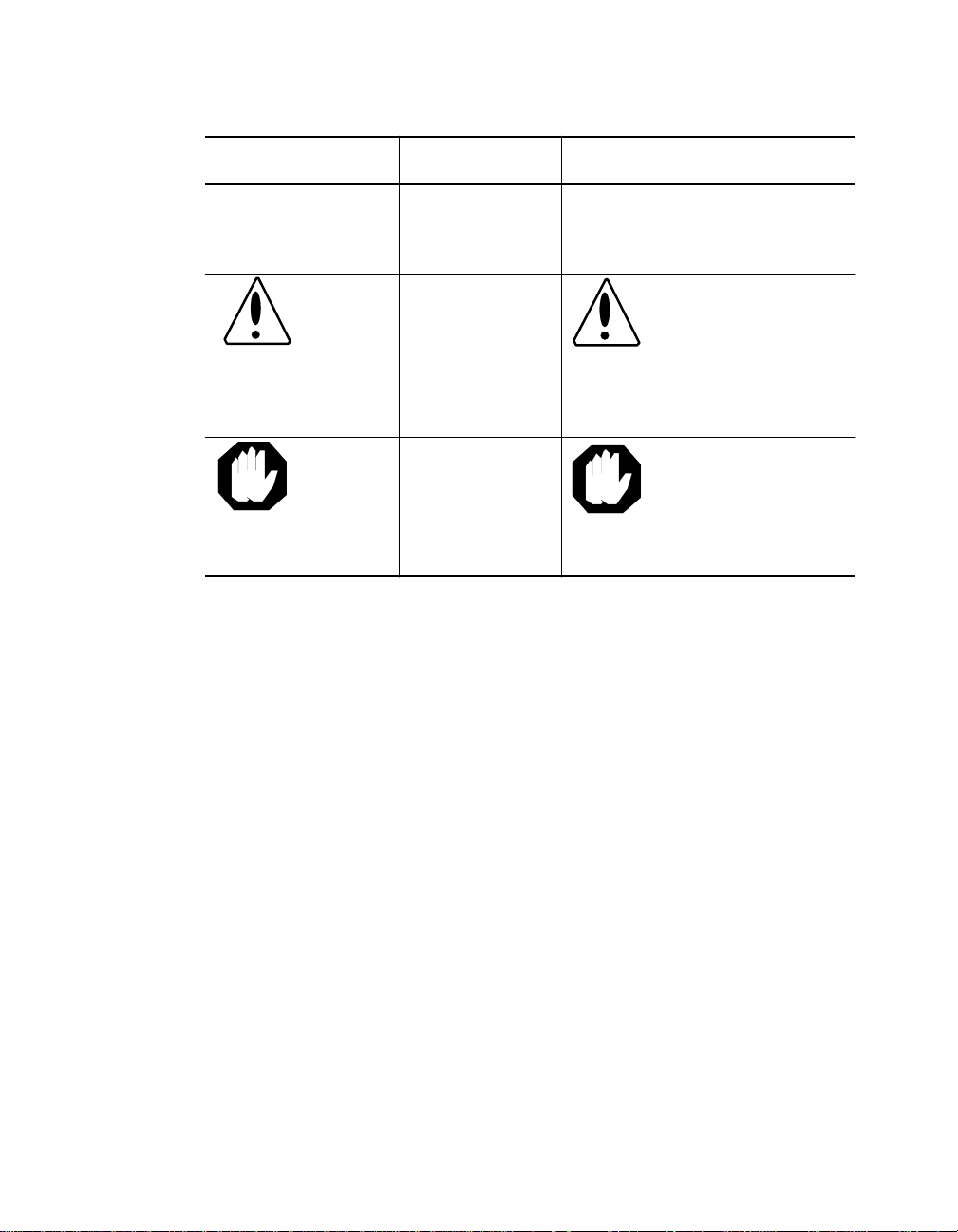
Convention Indicates Example
Note: A Note. The
Caution: A Caution. A
Warning: A Warning. A
Related Documents
This section provides in formation on supporting documentation, including:
❑ 3Com Documents
information is
important
condition may
damage
software or
hardware
condition may
threaten
personal safety
Note: Use STP lobe
cables for your system.
Caution: Do not put
your installation
diskettes on a
magnetic surfac e.
This may damage the
diskettes.
Warning: Wear eye
protection when
performin g these
maintenance
procedures.
❑ Reference Documents
xvi Ethernet RMON MultiProbe Module Installation and Operation Guide
Page 17

3Com Documents
The following documents provide additional information on 3Com
products:
ONline System Concentrator Installation and Operation Guide - Provides
information on the installation, op eration, and configuration of the
ONline System Concentrator. This guide also describes the principal
features of the ONline Fault-To lerant Controller Module.
ONcore Switch ing Hu b Installa tion an d Opera tion Gu ide - Provides
information on the installation, op eration, and configuration of the
ONcore Switching Hub. This guide also describes the principal features of
the ONcore Fault-Tolerant Controller Module.
ONline Ethernet Management Module Installation and Operation Guide Provides information on the operation , installation, and configuration of
the ONline Ethernet Management Module.
Distributed Management Module User’s Guide - Provides information on
the operation, installation, and configuration of the ONcore Distributed
Management Module. This guide also describes the software commands
associated with the Distributed Management Module.
ONline Ma nage me nt C omm and s Gu ide - Describes the software
commands associated with the ONline Management Modules.
Distributed M a nage me nt M odu le C omm an ds Gu ide - Describes each
management command by providin g detailed information on the
commands’s fo rmat, use, and description.
For a complete list of 3Com documents, contact your 3Com representative.
Ethernet RMON MultiProbe Module Installation and Operation Guide xvii
Page 18

Reference Documents
The following documents supply related background information:
Case, J., Fedor, M., Scoffstall, M., and J. Davin, The Simple Network
Management Protocol, RFC 1157, University of Tennessee at Knoxville,
Performance Systems International and the MIT Laboratory for Computer
Science, May 1990.
Rose, M., and K. McCloghrie, Structure and Identification of
Management Information for TCP/IP-based Internets, RFC 1155 ,
Performance Systems International and Hugh es LAN Systems, May 1990.
Waldbusser S., Remote Networ k Monitoring Management Information
Base, RFC 1757, Carnegie Mellon University, February 1995.
xviii Ethernet RMON MultiProbe Module Installation and Operation Guide
Page 19

1
Introduction
This chapter provides an introduction to the 3Com Ethernet RMON
MultiProbe Module (hereafter referred to as the RMON MultiProbe
Module). The RMON MultiProbe Module is managed by the following
3Com management modules:
❑ ONcore® Distributed Management Module (Version V2.10)
❑ ONline Ethernet Management Module (Version V4.20)
This chapter contains the following sections:
❑ RMON Overview
❑ RMON MultiProbe Module Overview
❑ RMON MultiProbe Module Features
Introduction 1 - 1
Page 20

RMON Overview
Remote Monitoring (RMON) is a standards-based network management
tool that allows you to efficiently and effectively monitor segments
throughout the network. You can use RMON to id en tify and isolate
potential problems in your network before disruptions occur.
RMON-compliant devices operate without impacting network operation.
They function as promiscuous devices, which listen to and capture data on
the network, but do not add ad ditional traffic.
The following sections describe :
❑ RMON Architecture
❑ Ethernet R MO N Groups
RMON Architecture
RMON techn ology requires two components within a network:
❑ RMON Probe
❑ RMON Client
RMON Probe
An RMON probe contains both hardware and software, and is referred to
as the RMON agent. As a promiscuous device, the RMON probe:
❑ Observes packets on the network
❑ Captures packets that match user-defined criteria
❑ Stores packets from the network segment
Through the packet capture and store feature, the RMON agent provides
an extensive set of Ethernet-based statistics to the network manage r.
1 - 2 Ethernet RMON MultiProbe Module Installation and Operation Guide
Page 21

RMON Client
The RMON Client consists of a management station running an application
that uses SNMP (such as the 3Com ONdemand LANsentry™ software) to
request data from the probe and display that data in various formats. You
can also use the graphical interface to configure the RMON agent.
The client application does not have to be located on the same segments as
the network to which the probe is assigned, but does need connectivity to
the networks.
Etherne t RMON Groups
The Ethernet RMON standard is defined in Request For Comment (RFC)
1757 (formerly 1271). The goal of the standard is to ensure interoperability
in multivendor environments. As defined by the RFC standards for Ethernet
RMON, the Ethernet RMON specification identifies the following RMON
groups:
❑ Alarm Group - Allows you to define and set thresholds for various
counters. If a counter reaches a predefined threshold, an event is
generated. (See Event Group below. )
❑ Event Group - Controls the action taken as a result of an event, (an
event can be triggered by an alarm). For example, if a counter
reaches a threshold, then a trap may be generated or an event may
be logged.
❑ Filter Group - Instructs the RMON Mult iProbe Module to capture
only those packets that match a specific criteria (such as IP Protocol
or a specific MAC address).
❑ History Group - Provides histo rical views of statistics based on
predefined sampling intervals. This information illustrates traffic or
error patterns, which can be useful in trend analysis.
❑ Host Group - Contains statistical counters, grouped by MAC address,
specific to each station on the network. This group also contains the
order in which devices or stations were discovered.
Introduction 1 - 3
Page 22

❑ HostT opN Group - Sorts stations by top traffic contributors. You can
use this information to identify the most active hosts on a segment or
the hosts producing the most errors.
❑ Matrix Group - Collects statistics between pairs of device s on the
network and tracks information specific to each connection, such as
the number of packets transmitted between devices.
❑ Packet Capture Group - Handles the capture and uploading of
packets collected by the RMON MultiProbe M odule.
❑ Statistics Group - Contains cumulative traffic and error statistics (for
example, packet distribution, and Cyclic Redundancy Check) for each
device being monitored.
1 - 4 Ethernet RMON MultiProbe Module Installation and Operation Guide
Page 23

RMON MultiProbe Modu le Overvi ew
The RMON MultiProbe Mo dule is a single-slot Ethernet mo dule that you
install in an ONline and ONcore hub. The RMON MultiProbe Module can
monitor up to three Ethernet networks simultaneou sly and perform all
functions on all networks in parallel.
The RMON MultiProbe Module supports:
❑ UDP/IP (User Datagram Protocol/Internet Protocol) over Ethernet
❑ SLIP (Serial Line Internet Protoco l )
❑ SNMP (Simple Network Management Protocol ) over UD P for
management access
❑ ICMP (Int e rnet Control Message Protocol) Echo and Redirect
Introduction 1 - 5
Page 24

RMON MultiProbe Modu le Features
When you use the RMON MultiProbe Module in conjunction with an RMON
client application, you can:
❑ Monitor the network
❑ Generate reports based on network information
❑ Filter and capture packets
❑ Process events and thresholds
❑ Detect network events
In addition, the RMON MultiProbe Module monitors:
❑ Per-network collisions
❑ Per-port collisions (PPC)
❑ Port-address correlation (PAC)
1 - 6 Ethernet RMON MultiProbe Module Installation and Operation Guide
Page 25

Other benefits of the RMON MultiProbe Module include:
❑ 3Com T riChannel™ Architecture - The RMON MultiProbe Module
operates in an ONline System Concentrator and an ONcore Switching
Hub.
❑ Slot Independence - Y ou can install modules into any available slot
in a 3Com ONline or ONcore hub. This flexibility eliminates the need
to shut down the network and rearrange the existing configuration
of the concentrato r when you install new modu les.
❑ Hot Swap Capability - Y ou can install or remove modules from the
ONline or ONcore hubs when the hub is pow ered up without
affecting the operation of any other modules in the concentrator.
❑ Management Support - You can manage the RMON M ultiProbe
Module through the 3Com® ONdemand LANsentry application. Y ou
can also manage the module using terminal management through an
ONline Ethernet Management M odule (EMM) or an ONcore
Distributed Management Module (DMM).
❑ Compliance - The 3Com Ethernet RMO N MultiProbe Module
complies with the RM O N standard as defined by RFC 1757 .
Introduction 1 - 7
Page 26

Theory of Operation
This section describes the theory of operation for the RMON MultiProbe
Module.
The RMON MultiProbe Module:
❑ Supports simultaneo us analysis of three Ethernet channels
❑ Monitors the network proactively
For example, when a network event occurs or a problem becomes
apparent in the network, you use a protocol analyzer to attempt to isolate
and correct the problem. RMON technology also provides you with
protocol analyzer capabilities. However , RMON takes a more proactive
approach to netwo rk monitoring by:
❑ Alerting you of network events before they can become a problem
❑ Providing you with information to help isolate problems
You can also confi gure the RMON MultiProbe Module to check
continuously for specific error conditio ns and notify you or log the event
when the conditions occur.
1 - 8 Ethernet RMON MultiProbe Module Installation and Operation Guide
Page 27
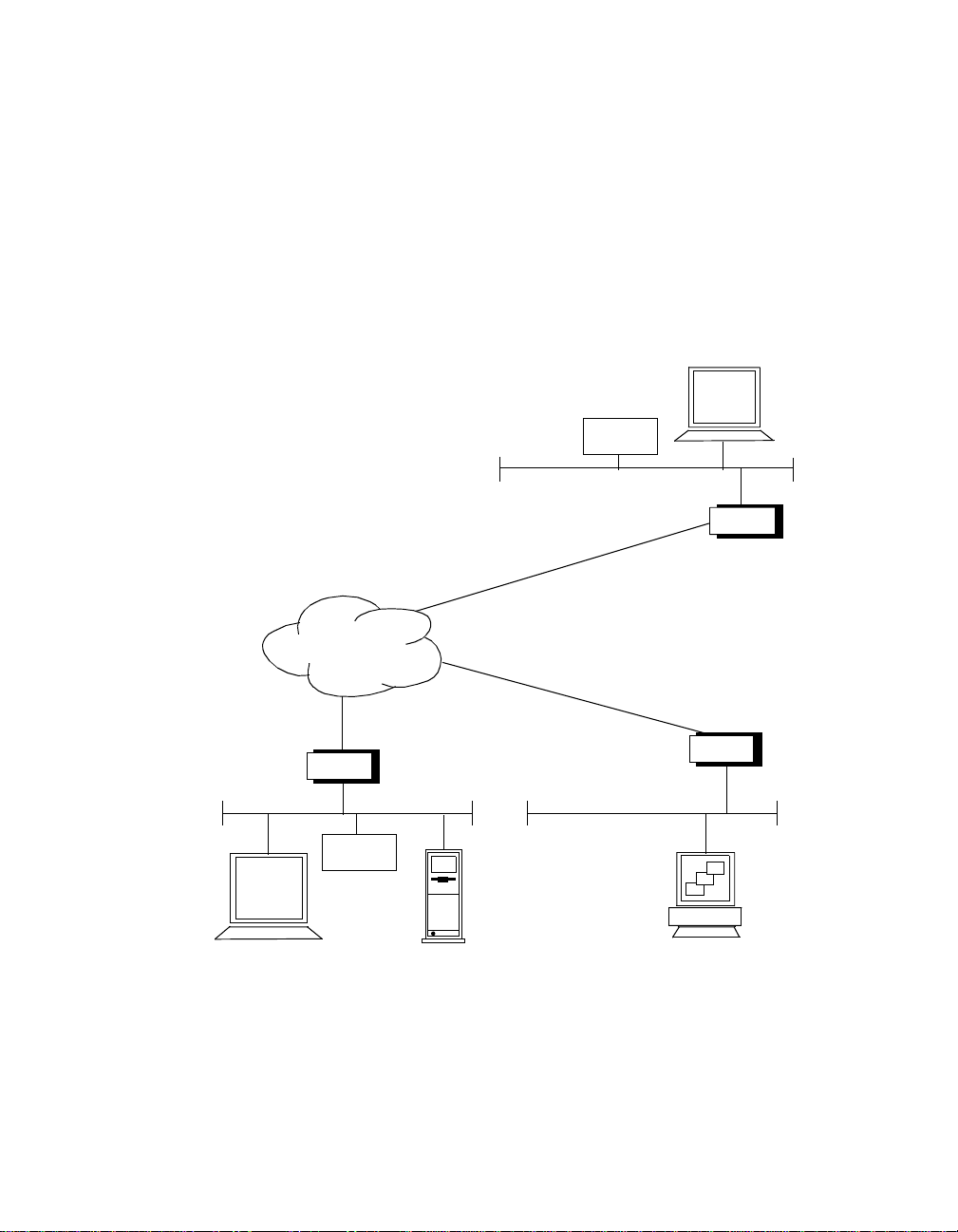
Sample Application
Figure 1-1 illustrates a sample application of RMON MultiProbe Modules in
a concentrator monitoring Ether net segments in Boston and New York.
With the appropriate interconnection s, yo u can view the RMON data
collected by the RMON MultiProbe Modules from a client w orkstation
application in Los Angeles
.
Router
RMON
Module
Boston
RMON
Module
Los AngelesNew York
Management
Console with
RMON Client
Application
Router
Router
Figure 1-1. RMON Sample Application
Introduction 1 - 9
Page 28

Page 29

2
Installing the Module
This chapter contains the following sections:
❑ Precautionary Procedures
❑ Quick Installation
❑ Unpacking Procedures
❑ Installing the RMON MultiProbe M odule
❑ Connecting a Terminal
❑ Initializing the RMON MultiProbe Module
❑ Monitoring the Front Panel
Installing the Module 2 - 1
Page 30

Precautionary Procedures
Caution: Electrostatic discharge (ESD) can damage
static-sensitive devices on circuit boards.
When you handle the module:
❑ Do not remove the boa rd from its antistatic shielding bag unt il you
are ready to inspect or install it.
❑ Handle the board by the faceplate only .
Use proper grounding techniques when you install the module, including:
❑ Using a footstrap and grounded mat or wearing a grounded static
discharge wrist stra p .
❑ Touching the grounded rack or other source of ground just before
you handle the module.
2 - 2 Ethernet RMON MultiProbe Module Installation and Operation Guide
Page 31

Quick Install atio n
Table 2-1 outlines the steps necessary to complete the installation of the
RMON MultiProbe Module. If you are familiar with installing 3Com
modules, use this table as a checklist. Otherwise, consult the remainder of
this chapter.
Table 2-1. Quick Installation Steps
Step Procedure Chapter/Section
1 U npack the module. Chapter 2, Unpacking
Procedures section
2 Install the module into an open slot in
the hub.
3 Connect a terminal or management
workstation to the RS-232 console port
on the module faceplate.
4 Assign an IP address a nd subnet mask
for each RMON interface using a
BOOTP server or the configuration
menus.
5 Assign a default gateway for the
module using the configuration menus
or BOOTP.
6 Configure the RMON interfaces to a
network using either the DIP switch or
the SET PORT command.
7 Configure optional module
parameters using the configuration
menus.
Chapter 2, Installing
the Module section
Chapter 2,
Connecting a T erminal
section
Chapter 3, Assigning
the Interface IP
Address and Subnet
Mask section
Chapter 3, Assigning
the Module Default
Gateway section
Chapter 3, Assigning
Interfaces to Networks
section.
Chapter 3, Configuring
the Modul e
Installing the Module 2 - 3
Page 32

Unpacking Procedures
To unpack the RMON MultiProbe Module:
1. Verify that the RMON MultiProbe Module (Model Number
RMON-EMP-3) is the model you ordered by checking the model
number listed on the side of the shipping carton.
Note that the product model number prin ted on the shipping box
differs from the model number on the product. The model number
on the shipping box contains the prefix ‘3C9’.
2. Remove the module, in its antistatic bag, from the shipping carton .
3. Remove the module from the antistatic shielding bag and inspect it
for damage.
Always handle the module by the faceplate, being careful not to
touch the components. If the module appears to be damaged, return
it to the anti-static shielding bag, repack it in the shipping carton, and
contact your local supplier.
Keep the shipping carton and anti-static shielding bag in which your
module was shipped so that you can repackage the module for storage or
shipment.
2 - 4 Ethernet RMON MultiProbe Module Installation and Operation Guide
Page 33

Installing t he RMON MultiProbe Module
You do not need to power down the hub to install or r emove the RMON
MultiProbe Module. You can insert the module while the hub is operating
(this is called a hot swap).
To install the RMON MultiProbe Module:
1. Properly ground yourself p rior to handling the module.
For example, wear a static wrist guard or touch a grounded static
mat prior to handling the m odule.
2. Locate an open slot in the hub. Remove a blank panel on the hub to
expose a slot for the module, if nec essary.
3. Insert the module into the board guides at the top and bottom of the
slot and slide it into the hub by pressing firmly at the top and bottom
of the faceplate. Make sure the connectors are well-seated into the
backplane of the hub.
Once you install the module, it automatically begins self-diagnostics
and initializes.
Installing the Module 2 - 5
Page 34

Figure 2-1 shows the RMON MultiProbe Module installed in an
ONline System Concentrator. You c an also install the RMON
MultiProbe Module in the ONcore MultiProtocol Switching Hub using
an ONline Module Adapter Kit.
RMON MultiProbe Module
Figure 2-1. RMON MultiProbe Module in the
ONline System Concentrator
4. Using your fingers, tighten the spring-loaded screws on the front of
the module faceplate (do no t overtighten). Once you install the
RMON MultiProbe Module, it begins diagnostic testing automatically.
5. Connect one end of an RS-232 cable to the RS-232 port on the front
of the module.
6. Connect the other end of the cable to a terminal (as described in the
next section).
2 - 6 Ethernet RMON MultiProbe Module Installation and Operation Guide
Page 35

Connecting a Terminal
You can co nnect a terminal or workstation runn ing a terminal emulation
program to th e R MO N MultiProbe Module RS-232 port to:
❑ Configure IP address information for the RMON MultiProbe Module
interfaces
❑ Display the RMON MultiProbe Modul e configuration
To connect a terminal to the RMON MultiProbe Module:
1. Verify that the terminal is configured as follows:
❑ 8-bit data
❑ No parity
❑ 1 stop bit
❑ 9600 baud rate
Note: The RMON MultiProbe Module does not support XON and
XOFF.
2. Using an RS-232 null-modem cable, attach a terminal (or a
workstation running ASCII terminal emulation software) to the
RMON MultiProbe Module RS-232 port.
Installing the Module 2 - 7
Page 36

Initializi n g the RM ON Multi P robe Mod ul e
Once you complete module installation procedures and attach an RS-232
cable to the front panel, you ca n initialize the RMON MultiProbe Module
and display the configuration menus.
To initialize the RMON MultiProbe Module and display th e configuration
menus:
1. Press the front panel Reset button. Pressing the Reset button
warm-starts the module. (Refer to Chapter 3, Configuring the
Module, for a description of warm and cold starts.)
When reset, the module comp letes diagn ostics and initializes.
2. To display the RMON MultiProbe Module Main configuration menu,
hold down the X key on the terminal keyboard within 15 seconds of
powering up or resetting the module. If you do not hold down the X
key within 15 seconds, the RMON MultiProbe Module:
a. Begins monitoring the network
b. Reports any error messages if the module experiences an error
condition
3. If you miss the 15-second window, press the Reset button to
re-initialize the module.
4. When you ho ld down the X key, the following banner is displayed:
Tests interrupted!
Boot System Version x.xx for Ethernet RMON
Multi Pr obe , Re v x
Built on Thu April x, 17:36:58 EST 199x
Loading configuration system.
Entering configuration system. Please
wait.....
2 - 8 Ethernet RMON MultiProbe Module Installation and Operation Guide
Page 37

The Main configuration menu appears (Figure 2-2).
Main menu Rev x.xx (Rev x.x)
1 Modify/View configuration values ->
2 Download new firmware ->
3 Warm start and Exit
4 Cold start and Exit
Enter one of: 1 2 3 4 ?
Figure 2-2. Main Configuration Menu
5. Refer to Chapter 3, Configuring the Module, for a description of the
configuration menus and instructions for configuring the module and
its interface s using the configuration menus.
Once you configure the RMON MultiProbe Module and it initializes
successfully , the module begins to operate normally and monitor the
network.
Note: Hardware flow control is not active on the RMON
MultiProbe Module when you are using the configuration
menus. Depending on the Serial Port Mode setting,
hardware flow control is active when you exit the
configuration menus.
For information on the Serial Port Mode settings, refer to Chapter
3, Configuring the Module, Table 3-4 Modify/V iew Serial
Configuration Values Menu Description.
Installing the Module 2 - 9
Page 38

Monitoring the Front Panel
Use the LEDs on the front panel of the RMON MultiProbe Module to
monitor the status of the module and the module interfaces. The RMON
MultiProbe Module front panel also contains a recessed Reset button for
resetting the module.
Resetting the module is equivalent to a warm start. Refer to Chapter 3,
Configuring the Module, the section titled Re-Initializing the RMON
MultiProbe Module for information on warm and co ld starts.
When you install the RMON MultiProbe Module in the hub, an Interface
Status LED illuminates for each interface after the following conditions are
met:
❑ The RMON MultiProbe Module completes self-d iagnostics and
initializes.
❑ You assign an interface to a network (the interface is enabled
automatically once you assign a network using a 3Com management
module or set the DIP switches).
The Module Status LED illuminates once the module completes
self-diagnostics and initializes (45 seconds).
2 - 10 Ethernet RMON MultiProbe Module Installatio n and Operation Guide
Page 39

Figure 2-3 shows the LEDs, Reset button, and RS-232 port on the module
faceplate. Each LED indicates the state of the m odule or interface as
described in Table 2-2.
Interface 1 LEDs
Interface 2 LEDs
Interface 3 LEDs
Status
Collision
Activity
Module Status
Module Reset
RS-232/SLIP Port
LEDs
LEDs
LEDs
Serial Activity
25-Pin Connecto r
Figure 2-3. RMON MultiProbe Module Front Panel LEDs
and Reset Button
Installing the Module 2 - 11
Page 40

Table 2-2. Module LED Interpretations
LED Name Color State Indicates
Interface1
Interface 2
Interface 3
(Interface Status)
Collision
(Interface
Collision)
Activity
(Interface
Activity)
Module Status Green Off Module failed diagnostics. This
Green Off Interface is set to isolated
(not assigned to any network).
On Interface is configured to a
network and is enabled.
Blinking LED blinks briefly during
diagnostics.
Yel low Off Interface is not experiencing
collisions or is isolated .
Blinking Interface is experiencing
collisions. Blinks once for each
collision detected.
Yellow Off No traffic is being passed or
interface is isolated.
Blinking Monitors received traffic.
Blinks once for each packet
received.
indicates an unrecoverable
hardware or software error .
Contact the 3Com Customer
Service Center.
On Module is operating correctly.
Blinking Blinks at 1-second intervals
during module initialization.
2 - 12 Ethernet RMON MultiProbe Module Installatio n and Operation Guide
Page 41

Table 2-2. Module LED Interpretations (Conti nue d)
LED Name Color State Indicates
Serial Activity Yellow Blinking Activity over the RS-232 port.
Blinks once for each character
received or transmitted.
Reset Button Black When
pressed
Re-initializes module software
and resets module hardware.
Installing the Module 2 - 13
Page 42

Page 43

3
Configuring the
Module
This chapter describes how to configure the 3Com Ethernet RMON
MultiProbe Module fo r op er ation.
This chapter contains the following sections:
❑ Configuration Menu Overview
❑ Configuring the Module and Interfaces
❑ Assigning Interfaces to Networ ks
❑ Showing Module and Interface Configurations
❑ Re-initializing the RMON Mult iProbe Module
Configuring the Module 3 - 1
Page 44

Configuration Menu Overview
This section describes the RMON MultiProbe Module configuration menus
and how to use the menus to configure the module and interface. The
configuration menus enable you to configure the module and interfaces
using a terminal attached to the front panel RS-232 port and an RS-232
null-modem cable. (Refer to Appendix A, Specifications, for information on
cable pinouts.)
This section includes:
❑ Modifying Configuration Menu Values
❑ Using the Main Configuration Menu
❑ Using the Download Menu
❑ Using the Modify/View Configuration Values Menu
❑ Using the Modify/View Serial Configuration Values Menu
❑ Using the Modify/View Network Settings Menu
❑ Using the Modify/View Network Interface Settings Menu
3 - 2 Ethernet RMON MultiProbe Module Installation and Operation Guide
Page 45

Figure 3-1 is a flow chart of the RMON MultiProbe Module configuration
menus.
Main Me nu
1 Modify/View configuration values
2 Download new fi rm wa re
3 Warm start and Exit
4 Cold start and Exit
Enter one of: 1 2 3 4 ?
1 Modify/View Configuration Values
1 Modify/View network settings
2 Autodiscovery echo interval (secs)
3 Date
4 Time
5 Timezone
6 Modify/View serial port settings
S Save changes and exit
0 Cancel changes and exit
2 Download Menu
1 Filename to download
2 tftp server IP address
3 Download to firmware
4 Temporary dow nl oa d
0 Return to previous menu
3
Warm-start the module
and exit
Cold-start th e mo du le
and exit m en us
6 Modify/View Se rial
Configurat io n Val ues
1 Serial port IP address
2 Serial port subnet mask
3 Serial port speed
4 Serial port mode
5 Modem Init String
6 Modem Hangup String
7 Modem Connect Responses
8 Modem No-Connect Responses
S Save changes and exit
0 Cancel changes and exit
menus
4
Modify/View network settings menu shown on next page
Figure 3-1. Configuration Menu Flow Chart
Configuring the Module 3 - 3
Page 46

1 Modify/View Network Settings Menu
1 Modify/View settings for network interface 1
2 Modify/View settings for network interface 2
3 Modify/View settings for network interface 3
4 Default gateway IP address
5 BOOTP network interface
Enter one of: 1 2 3 4 5 ?
1,2,and 3 Modify/View network interface x settings
MAC address 08 11 22 33 44 55
1 IP address
2 Subnet mask
S Save changes and exit
0 Cancel changes and exit
Enter one of: 1 2 S 0?
Figure 3-1. C onfiguration Menu Flow Chart (Continued)
The following sections provide examples of each configuration menu. Each
section also contains a table describing t he menu options.
3 - 4 Ethernet RMON MultiProbe Module Installation and Operation Guide
Page 47

Modifying Configuration Menu Values
The configuration menus contain opt ions that enable you to:
❑ Display additional configuration menus
❑ Display and modify configuration values
T o display a menu from within a menu, type the number of the option and
press Return.
To display or m odify a value from a configuration menu:
1. Type the number of the option you want to display or modify and
press Return. The configuration menus have a timeout value of 2
minutes. Therefore, you must enter a keystroke to a menu within 2
minute s or the following me ssage displays and the module
automatically warm-starts.
Keyboard input timeout.
Module warm started and config system exited.
2. To modify configuration menu values, delete one character at a time
using the Backspace key. To delete the entire value, press Ctrl-U.
When you press Ctrl-U, <CANCEL> appears at the end of the curr ent
value to verify that the current value is canceled.
3. Enter the new value and press Return.
4. Select S to save changes and exit the current menu, or 0 (zero) to
cancel changes and exit the current menu. Exiting a current menu
brings you up one menu level. When you return to the Main menu,
you must select either a warm or cold start to re-initialize the RMON
MultiProbe Module.
5. To re-initialize the RMON MultiProbe Module, select option 3 for a
warm start or select option 4 for cold start.
(Refer to the section R e-initializing the RMON MultiProbe Module
later in this chapter for information on the effects of warm and cold
starts.)
Configuring the Module 3 - 5
Page 48

Using the Main Configuration Menu
Use the Main configuration menu to:
❑ Display the Modify/View Configuration V alues menu
❑ Download new firmware
❑ Initiate a warm or cold start
To display the Main configuration menu:
1. Press the front panel Reset button to re-initialize the module.
2. Hol d down the X key within 15 seconds of powering up or resetting
the module.
3. If you miss the 15-second window, press the Reset button to
re-initialize (warm start) the module.
4. When you hold down the X key, diagnostics are terminated and the
following banner is displayed:
Tests interrupted!
Boot System Version x.xx for Ethernet RMON
Multi Pr obe , Re v x
Built on Thu April x, 17:36:58 EST 199x
Loading configuration system.
Entering configuration system. Please
wait.....
3 - 6 Ethernet RMON MultiProbe Module Installation and Operation Guide
Page 49

The Main conf iguration menu appears (Fig ure 3-2) .
Main menu Rev x.xx (Rev x.x)
1 Modify/View configuration values ->
2 Download new firmware ->
3 Warm start and Exit
4 Cold start and Exit
Enter one of: 1 2 3 4 ?
Figure 3-2. Main Configuration Menu
The configuration menus for options 1 and 2 are described in the following
sections. Options 3 and 4 are described in the section Re-initializing the
RMON MultiProbe Module later in this chapter.
Configuring the Module 3 - 7
Page 50

Table 3-1 describes the Main menu options.
Table 3-1. Main Configuration Menu Description
Option Result
1.
Modify/View
configuration
menu
2.
Download new
firmware
3.
Warm start and
Exit
4.
Cold start and Exit
Displays the Modify/View Configuration Value
menu. For a description of this menu, refer to the
section Using the Modify/View Configuratio n
Value Menu later in this chapter.
Downloads new firmware to FLASH memory . For
a description of this menu, refer to the section
Using the Download Menu later in this chapter.
Warm-starts the module and exits the menu
system.
Cold-starts the mod ule and exits the menu
system.
3 - 8 Ethernet RMON MultiProbe Module Installation and Operation Guide
Page 51

Using the Download Menu
Use the Download menu to:
❑ Configure the RMON MultiProbe Module for a software download
❑ Display the current IP address and subnet mask for each interface
To display the Download menu, select option 2 from the Main
configuration menu.
Figure 3-3 is an example of the Dow nload menu.
.
Download Menu Rev x.xx
1 Filename to download ->
/chome/spe/onown/rmon_mod/mar06/ax3_field.rom.cf.1.20
2 tftp server IP address ->
3 Download to firmware ->
4 Temporary download
0 Return to previous menu
IP address 1:
Subnet mask 1:
IP address 2:
Subnet mask 2:
IP address 3:
Subnet mask 3:
Default gateway IP address: 151.104.6.1
Enter one of: 1 2 3 4 0 ?
151.104.3.6
151.104.6.7
255.255.255.0
151.104.7.8
255.255.255.0
151.104.8.9
255.255.255.0
Figure 3-3. Download Menu
Configuring the Module 3 - 9
Page 52

Table 3-2 describes the Download menu options.
Ta b le 3-2. Download Menu Descrip tion
Option Result
1.
Filename to
download
2.
TFTP Server IP
address
3.
Download to
firmware
4.
Temporary
download
Displays the pathname of the file to download and
enables you to enter a new value. The filename can
be a maximum of 127 characters.
If the download file:
❑ Resides in the /tftpboot directory of the server,
you only need to enter the filename.
❑ Does not reside in the /tftpboot directory, you
must entire the complete directory path.
Displays the TF TP server IP address and enables you
to enter a new value.
Initiates a download to FLASH memory.
Initiates a download to RAM. This option enables
you to run and verify the new software before you
initiate a download to FLASH memory . After being
reset, the module reverts to the software contained
in FLASH memory.
0.
Return to previous
Closes the current menu and returns to the Main
menu.
menu
3 - 10 Ethernet RMON MultiProbe Module Installatio n and Operation Guide
Page 53

Using the Modify/View Configuration Values Menu
Use the Modify/View Configuration Values menu to:
❑ Set module values (such as date and time)
❑ Display the Modify/View Network Settings menu
❑ Display the Modify/View Serial Port Settings menu
To display this menu, select option 1 from the Main configuration menu.
Figure 3-4 is an example of the Conf iguration Values menu.
Modify/view configuration values menu Rev N.NN
Memory configuration 8M bytes
Three ethernet ne twork interface s
1 Modify/View network settings
2 Autodiscovery echo interval (secs)
3 Date
4 Time
5 Timezone
6 Modify/View serial port setting s
S Save changes and exit
0 Cancel changes and exit
Enter one of: 1 2 3 4 5 6 S 0 ?
Figure 3-4. Modify/View Configuration Values Menu
1800
Sat 1/28/199 5
22:45:05
PST
Configuring the Module 3 - 11
Page 54

Table 3-3 describes the Configuration Values menu options.
Table 3-3. Modify/View Configuration Values Menu
Description
Option Result
1.
Modify/View
network settings
2.
Autodiscovery
Echo Interval
3.
Date
4.
Time
5.
Timezone
6.
Modify/View
Serial Port settings
Displays the Modify/View Network Settings menu.
For a description of this menu, refer to the section
Using the Modify/View Network Settings menu.
Displays the Autodiscovery Echo Interval and
enables you to enter a new interval (in seconds)
after which the RMON MultiProbe Module sends
an Internet Control Messa ge Protocol (ICMP) echo
request to the default gateway.
Displays the date and enables you to enter a new
value. Use the format: mm/dd/yyyy . Changes are
saved immediately and cannot be canceled. To
correct an error, re-enter the date.
Displays the time and enables you to enter a new
value. Use the format hh:mm:ss. Changes are
saved immediately and cannot be canceled. To
correct an error, re-enter the time.
Displays the time zone and enables you to enter a
new value (for example, EST, GMT).
Displays the Serial Port Configuration menu
containing the current serial port settings. For a
description of this menu, refer to the section Using
the Serial Port Configuration menu later in this
chapter.
3 - 12 Ethernet RMON MultiProbe Module Installatio n and Operation Guide
Page 55

Table 3-3. Modify/View Configuration Values Menu
Description (Continued)
Option Result
S
Save Changes and
Exit
0
Cancel Changes
and Exit
Note: All configuration settings except for the Autodiscovery
Echo Interval field value are preserved after a cold start.
Saves all changes to the configuration menu to
non-volatile memory and returns to the Main
menu.
Cancels changes to the configuration menu and
retu rns to the Main menu.
Using the Modify/View Serial Configuration Values Menu
Use the Modify/View Serial Configuration Values menu to co nfigure the
module RS-232 serial port to run Serial IP (SLIP):
❑ Over a direct link
❑ Using a modem
The Serial IP feature enables the RMON MultiProbe Module and a network
management workstation to communicate when a network link is not
available.
To display this menu, select option 6 from the Modify/View Configuration
Values Menu and press Return. The Serial Conf iguration Values menu is
displayed with factory-default settings for the serial port (Figure 3-5).
Configuring the Module 3 - 13
Page 56

Figure 3-5 is an example of the Serial Configuration Values menu options.
Modify/view serial configuration values menu Rev N.NN
1 Serial port IP address
2 Serial port subnet mask
3 Serial port speed
4 Serial port mode
5 Modem Init String
6 Modem Hangup String
7 Modem Connect Responses
/CONNECT/300/CONNECT 1200/1200/CONNECT
2400/ 24 00/CONN EC T 48 00/4800/CONNE CT
9600/ 96 00/CONNECT 1440 0/ 14 400/CONNECT
19200 /1 9200/CONNECT 38 40 0/ 38400/
8 Modem No-Connect Responses
/NO CARRIER/BUSY/NO DIALTONE/NO ANSWER/ERROR/
S Save changes and exit
0 Cancel changes and exit
Enter one of: 1 2 3 4 5 6 7 8 S O ?
187.187.187.193
255.255.255.192
9600
Direct
^s^MATEOQ0V1X4 S0=1 S2=43^M^d2
^d2^s+++^d2^s^ATH0^M^d2
Figure 3-5. Modify/View Serial Configuration Values Menu
3 - 14 Ethernet RMON MultiProbe Module Installatio n and Operation Guide
Page 57

Table 3-4 describes the Serial Configuration Values menu options .
Table 3-4. Modify/View Serial Configuration Values
Menu Description
Option Result
1
Serial Port IP Address
2
Serial Port Subnet
Mask
3
Serial Port Speed
4
Serial Port Mode
Displays the serial IP address of the RMON
MultiProbe Module and enables you to enter a
new IP address.
Not used.
Displays the serial port speed that s ets the
baud rate used by the serial interface and
enables you to enter a new value. Valid values:
1 = 300
2 = 1200
3 = 2400
4 = 4800
5 = 9600
6 = 14400
7 = 19200
8 = 38400
Display the serial connection value which
indicates whether or not the connection is
direct or is using a modem and enables you to
enter a new value. Valid values:
1 = direct
2 = modem
3 = direct with hardware flow control
4 = modem with hardware flow control
Configuring the Module 3 - 15
Page 58

Table 3-4. Modify/View Serial Configuration Values
Menu Description (Continued)
Option Result
5
Modem Init String
6
Modem H angup
String
7
Modem Connect
Response
8
Modem No Connect
Response
S
Save Changes and
Exit
0
Cancel Changes and
Exit
Display the modem init string and enables you
to enter a new value. In modem mode, this
string initializes the modem.
Displays the modem hangup string and enables
you to enter a new value. In modem mode, this
string hangs up the modem.
Displays the modem connect response and
enables you to enter a new value. In modem
mode, this string contains valid modem
connect responses and the baud rate to which
the serial port should be set.
Displays the modem no connect response and
enables you to enter a new value. In modem
mode, this string lists the modem connection
failure response codes.
Saves changes to the serial port configuration
menu to non-volatile memory and returns to
the Modify/View Configuration Values menu.
Cancels changes to the configuration menu
and re turns t o the Modify/View Configuration
Values menu.
Note: All serial configuration information is preserved after a cold
start.
3 - 16 Ethernet RMON MultiProbe Module Installatio n and Operation Guide
Page 59

Modem Init Strings and Hangup Strings
This section describes the format of the mod em:
❑ Init Strings
❑ Hangup Strings
T o allow the RMON MultiProbe Module to communicate with a modem or
a serial data switch, use the modem Init String and Hangup String. The
strings contain embedded commands to control how the module interacts
with a remote device through the serial interface. Commands are
represented as 2-character sequences beginning with the ^ character.
Table 3-5 describes the modem Init Strings and Hangup Strings that the
RMON MultiProbe Module supp orts.
Note: Command characters are case-sensitive.
Table 3-5. Modem Init Strings and Hangup Strings
Command Result
^s Sends string that follows, which is terminated by the
next command o r the end of string.
^c Delays for the number of seconds that follows. Discard
any data received instead of storing i t in a buffer for
parsing.
^t Sets timeout to the value represented by the decimal
digits that follow. The default timeout is 20 seconds. The
timeout may be overridden by a smaller serial Timeout
configured for the associated serial interface.
Configuring the Module 3 - 17
Page 60

Table 3-5. Modem Init Strings and Hangup Strings (Continued)
Command Result
^w Waits for the reply string that follows which is
terminated by the next command or the end of string.
Partial and case insensitive matching is applied (that is, if
the RMON MultiProbe Module finds the reply string [any
case combination] anywhere in the received string, the
match is found). If the current timeout elapses without a
match, the module ignores the remaining control string.
^! The ^ character.
^d Delays the number of seconds specified by the decimal
digits that follow.
^b Sends break for the number of milliseconds specified by
the decimal digits that follow. If no digits follow, br eak is
enforced for 250 ms by default.
You m ay insert the following ASCII con trol charac ters into the ^s send
string or the ^w reply string:
^@ 0x00
^A 0x01
^M 0x0D
^Z 0x1A
^[ 0x1B
^\ 0x1C
^] 0x1D
^^ 0x1E
^_ 0x1F
3 - 18 Ethernet RMON MultiProbe Module Installatio n and Operation Guide
Page 61

You may also insert binary data into the data stream using the following
control sequence for each byte of binary data: ^0x## (where ## is the
hexadecimal representation of the data byte).
Two ASCII characters (0-9, a-f, A-F) must follow the ^0x control prefix. For
example, ^0x0 D^0x0 A is interpreted as a carriage return followed by a line
feed.
Modem Response Strings
This section describes the modem response string formats:
❑ Connect Response Strings
❑ No Connect Respon se Strings
Connect Response - An ASCII string that contains substrings that describe
the expected modem connection response code and associated bps rate.
The substrings are delimited by the first character in th e string.
The following connect response string example is interpreted in Table 3-6.
CONNECT/300/CONNECT 1200/1200/CONNECT
2400/2400/CONNECT 4800/480 0/CONNECT 9600/9600
Table 3-6. Connect Response Strin g Example
Response code Bps rate
CONNECT 300
CONNECT1200 1200
CONNE CT 24 00 2400
CONNE CT 48 00 4800
CONNE CT 96 00 9600
Configuring the Module 3 - 19
Page 62

The RMON MultiProbe Module uses the information in this string to adjust
the bps rate of the serial interface once you establish a modem connection.
No Connect Response - An ASCII string that contains response codes
generated by a modem to report the reason for a connection attem pt
failure. The response codes are delimited by the first character in the string.
For example:
/NO CARRIER /BUSY/NO DIALTONE/NO ANSWER/ERROR/
If the RMON MultiProbe Module receives one of the response codes on its
serial interface while attempting to make a modem connection, the module
issues the hangup command as specified by modem Hangup String.
Using the Modify/View Network Settings Menu
Use the Modify/View Network Settings menu to:
❑ Display the Modify/View Network Interface Settings menu for each
interface
❑ Display and modify the module default gateway
❑ Display and modify the BOOTP network interface
To display this menu, select option 1 from the Modify/View Configuration
Values menu.
3 - 20 Ethernet RMON MultiProbe Module Installatio n and Operation Guide
Page 63

Figure 3-6 is an example of the Modify/View Network Settings menu.
Modify/View Ne twork Setti ngs Menu
1 Modify/View settings for network interface 1
2 Modify/View settings for network interface 2
3 Modify/View settings for network interface 3
4 Default gatewa y IP add ress
5 BOOTP network interface
S Save changes and exit
0 Cancel change s an d ex it
Enter one of: 1 2 3 4 5 S 0?
Figure 3-6. Modify/View Network Settings Menu
151.104.3.6
1
Configuring the Module 3 - 21
Page 64

Table 3-7 describes the Modify/View Network Settings menu options.
Table 3-7. Modify/View Network Settings Menu Description
Option Result
1
Modify/View
settings for
network
interface 1
2
Modify/View
settings for
network
interface 2
3
Modify/View
settings for
network
interface 3
4
Default gateway
IP address
5
BOOTP network
interface
Displays the Modify/View Network Interface 1
Settings menu. For a description of this menu,
refer to the section Using t he Modify/View
Network Interface Settings menu later in this
chapter.
Displays the Modify/View Network Interface 2
Settings menu. For a description of this menu,
refer to the section Using t he Modify/View
Network Interface Settings menu later in this
chapter.
Displays the Modify/View Network Interface 3
Settings menu. For a description of this menu,
refer to the section Using t he Modify/View
Network Interface Settings menu later in this
chapter.
Displays the default gateway IP address for the
module and enables you to enter a new value.
Displays the network interface configured for
BOOTP and enables you to enter a new value.
3 - 22 Ethernet RMON MultiProbe Module Installatio n and Operation Guide
Page 65

Table 3-7. Modify/View Network Settings Menu Description
(Continued)
Option Result
S
Save Changes
and Exit
0
Cancel Changes
and Exit
Saves all changes made to the configuration menu
to non-volatile memory and returns to th e
Modify/View Configuratio n Values menu.
Cancels changes made to the Configuration menu
and returns to the Modify/View Configuration
Values menu.
Using the Modify/View Network Interface Settings Menus
Each interface has a Modify/View Network Interface Settings menu. Use
the interface menus to:
❑ Display the module MAC address
❑ Display and modify the interface IP address
❑ Display and modify the interface subnet mask
To display a Modif y/View Network Interface Settings menu for an
interface, select option 1, 2, or 3 from the Modify/View Network Settings
menu.
Figure 3-7 is an example of the Modify/View Network Interface 1 Settings
menu
Configuring the Module 3 - 23
Page 66

.
Modify/View Network Interface 1 Settings Menu
MAC address 08 11 22 33 44 55
1 IP address
2 Subnet mask
S Save changes and exit
0 Cancel change s an d ex it
Enter one of: 1 2 S 0?
151.104.6.7
255.255.255.0
Figure 3-7. Modify/View Network Interface 1 Settings Menu
3 - 24 Ethernet RMON MultiProbe Module Installatio n and Operation Guide
Page 67

Table 3-8 describes the Modify/View Network Interface Settings menu
options.
Table 3-8. Modify/View Network Interface Settings Menu
Description
Option Result
1
IP address
2
Subnet Mask
S
Save Changes and
Exit
0
Cancel Changes
and Exit
Displays the interface IP address and enables you to
enter a new value.
Displays the interface subnet mask and enables you
to enter a new value.
Saves all changes made to the Inter face menu to
non-volatile memory and returns to the
Modify/View Network Set tings menu.
Cancels changes made to the Interface menu and
retu rns to the Modify/View Network Settings
menu.
Configuring the Module 3 - 25
Page 68

Configuring the Module and Interfaces
Before the RMON MultiProbe Module can become operational, you must
configure the follow ing parameters for the mod ule and interfaces:
❑ IP address (for each interface)
❑ Subnet mask (for each interface)
❑ Default gateway (for the module)
Assigning the Interface IP Address and Subnet Mask
You must assign a unique IP network address for each interface.
For example, if you do not bridge the three interfaces, you could assign IP
addresses for a subnetted class B network as shown in the following IP
address examples:
Note: In both of the IP address examples, each interface has a
subnet mas k of 255.255.255.0.
❑ Interface 1 - 151.104.36.7
❑ Interface 2 - 151.104.37.8
❑ Interface 3 - 151.104.38.9
For example, if you bridge the three interfaces, the network portion of the
IP addresses can be identical as shown in the follo wing IP address
examples:
❑ Interface 1 - 151.104.36.7
❑ Interface 2 - 151.104.36.8
❑ Interface 3 - 151.104.36.9
3 - 26 Ethernet RMON MultiProbe Module Installatio n and Operation Guide
Page 69

This configuration sets up one interface for each bridged segment.
To assign an IP address or subnet mask for an interface:
1. From the Main menu, select option 1, Modify/View Configuration
Values, and press Return. The Modify/View Configuration Values
menu is displayed (see Figure 3-4).
2. From the Modify/View Configuration Values menu, select option 1,
Modify/View Network Settings, and press Return. The Modify/View
Network Settings menu is displayed (see Figure 3-6).
3. From the Modify/View Network Settings menu, select option 1, 2, or
3 (depending on which interface you want to modify) and press
Return. The Modify/View Netw ork Interface 1 Settings menu is
displayed (Figure 3-7).
4. To assign:
a. An IP address, select option 1. The module displays the current
value and prompts you to enter a new valu e.
b. A subnet mask, select option 2. The module displays the current
value and prompts you to enter a new valu e.
5. To modify an IP address or subnet ma sk, delete one character at a
time using the Backspace key. T o delete the entire value, pr ess Ctrl-U.
6. Enter the new value and press Return.
7. Select S to save the changes and return to the previous menu.
8. Repeat steps 3 through 7 to assign an IP address and subnet mask
for each interface.
Configuring the Module 3 - 27
Page 70

Assigning the Module Defau lt Gateway
You must assign a default gatew ay for the RMON MultiProbe Module.
To assign a default gateway:
1. From the Main menu, select option 1, Modify/View Configuration
Values, and press Return. The Modify/View Configuration Values
menu is displayed (see Figure 3-4).
2. From the Modify/View Configuration Values menu, select option 1,
Modify/View Network Settings, and press Return. The Modify/View
Network Settings menu is displayed (see Figure 3-6).
3. From the Modify/View Network Settings menu, select option 4 and
press Return. The module displays the current default gateway and
prompts you to enter a new value .
4. Enter the new default gatewa y.
5. To save the changes and return to the previous menu, select S.
3 - 28 Ethernet RMON MultiProbe Module Installatio n and Operation Guide
Page 71

Using BOOTP to Configure the Module and Interfaces
This section describes:
❑ BOOTP Description
❑ BOOTP Configuration Process
❑ BOOTP Requirements
❑ Using BOOTP
BOOTP Description
BOOTP (Bootstrap Protocol) is a UDP/IP-based (User Datagram
Protocol/Internet Protocol) broadcast protocol which allows a device to
configure itself dynamically without user intervention. Use BOOTP to
download configuration information from a BOOTP server to the RMON
MultiProbe Module interface configured for BOOTP.
BOOTP Configuration Process
During initialization, the RMON MultiProbe Modul e verifies that the IP
address and subnet mask of the interface configured for BOOTP is not set
to null (all zeros). If either the IP address or subnet mask are null, the
module automatically sends out BOOTP requests every 60 seconds through
the designated BOOTP interface until it receives a valid BOOTP response. If
the default gateway is originally set to null, the BOOTP server also supplies
the module with gateway information.
The response from the BOOTP server supplies the RMON MultiProbe
Module with its network parameters. When BOOTP obtains valid addresses,
the module stores the parameters in battery-backed RAM and becomes
operational.
The RMON MultiProbe Module defaults to interface 1 for a BOOTP server.
Because only one interface at a time can be used with BOOTP, you can only
download configuration information to the interface configured for BOOTP .
Configuring the Module 3 - 29
Page 72

To configure other interfaces, use the Modify/View Network Settings
configuration menu to change the BOOTP network interface.
BOOTP Requirements
The BOOTP server must perform the following funct ions:
❑ Map hardware addresses to IP addresses
❑ Respond to BOOTP requests from clients
❑ Support the vendor-specific subnet mask and default gateway fields
Using BOOTP
To use BOO TP, add the following information to the BOOTP server
bootptab configuration file:
❑ MAC add res s - Hardware address of the RMON MultiProbe Module
interface to be configured
❑ IP address - IP address for the module interface
❑ Subnet mask - Subnet mask for the module interface
❑ Default gateway - Default gateway for the RMON MultiProbe
Module
For additional information on BO OTP configurations, refer to your server
documentation.
Sample BOOTPtab file
A sample bootptab file is shown on the next page. If necessary , create t his
file on the BOOTP server.
3 - 30 Ethernet RMON MultiProbe Module Installatio n and Operation Guide
Page 73

# /etc/bootptab: database for bo otp server (/etc/bootpd)
# Blank lines and lines beginning w ith '#' are ignored.
#
# Legend:
#
# first field -- hostname
# (should be full domain name)
#
# hd -- home directory
# bf -- bootfile
# cs -- cookie servers
# ds -- domain name servers
# gw -- gateways
# ha -- hardware address
# ht -- hardware type
# im -- impress servers
# ip -- host IP address
# lg -- log servers
# lp -- LPR servers
# ns -- IEN-116 name servers
# rl -- resource location protocol servers
# sm -- subnet mask
# tc -- template host (points to similar host entry)
# to -- time offset (seco nds )
# ts -- time servers
# Define a global entry which specifies th e information every host uses.
#
global.dummy:\
:hd=/tftpboot:bf=null
# Define different master entries for each subnet. . .
default:vm=rfc1048:hd=/tftpboot:bf="null":sm=255.255.255.0:
js-test-64:ip=151.104.15.2:\
ht=ethernet:\
ha=081122334455:\
gw=151.104.15.1:\
tc=default
Configuring the Module 3 - 31
Page 74

Assigning Interfaces to Networks
To assign RMON MultiProbe Module interfaces to networks, you can use
either:
❑ DIP switch settings, if your hub is unmanaged (an ONline or ONcore
management module is not installed in the hub).
❑ ONline or ONcore network management commands (if an ONline or
ONcore manageme nt module is installed in the hub).
Y ou can assign the three RMON MultiProbe Module network interfaces as
follows:
❑ Interface 1 to Ethernet 1 or Isolated
❑ Interface 2 to Ethernet 2 or Isolated
❑ Interface 3 to Ethernet 3 or Isolated
Note: Each interface can only be configured to its corresponding
Ethernet networ k or isolated (that is, Interface 1 to
Ethernet 1, Interface 2 to Ethe rnet 2, Interface 3 to
Ethernet 3).
3 - 32 Ethernet RMON MultiProbe Module Installatio n and Operation Guide
Page 75

Using the DIP Switch to Assign Networks
If you have an unmanaged hub, use the DIP switch on the module to assign
networks to the RMON MultiProbe Module interfaces. However, the DIP
switch settings are ignored if the fo llowing two conditions are met:
❑ A network management module is installed in the hub.
❑ The master management module has DIP_CONFIGURATION disabled.
The RMON Mult iProbe Module contains an 8-posi tion DIP switch (SW1).
This DIP switch allows you to configure and enable the three RMON
MultiProbe Module interfaces to the corresponding Ethernet networks.
Figure 3-8 shows the DIP switch location on the module
.
SW1
Dip Switches
On
Off
0
12345678
1
CH1EN
CH2EN
NOT USED
NOT USED
NOT USED
CH3EN
Figure 3-8. DIP Switch Location
Backplane DI N
Connector
NOT USED
NOT USED
Configuring the Module 3 - 33
Page 76

T able 3-9 describes the positions of the DIP switches required to configure
and enable the RMON MultiProbe Module interfaces to corresponding
Ethernet networks. As the table shows, switches 1, 2, 6, 7, and 8 are not
used.
Ta b le 3-9. Network Selection DIP Switch Settings
Switch
Setting
Network Selection
ON OFF
1 Reserved
2 Reserved
3 Ethernet 1 Isolated
4 Ethernet 2 Isolated
5 Ethernet 3 Isolated
6 Reserved
7 Reserved
8 Reserved
3 - 34 Ethernet RMON MultiProbe Module Installatio n and Operation Guide
Page 77

Using Management Commands to Assign Interfaces to
Networks
With a terminal attached to a 3Com management module console, you can
use management commands to assign the RMON MultiProbe Module
interfaces to networks.
The following 3Com network management modules enable you to assign
interfaces to networks:
❑ ONline Ethernet Management Module (EMM) (Version V4.20)
❑ ONcore Distribu ted Management Mo dule (DMM) (Version V2.10)
To configure all other RMON MultiProbe Module parameters (such as
IP address, subnet mask, and serial configurations), use the RMON
MultiProbe Mod ule co nfiguration menu s.
Examples of the management commands for assigning networks are
discussed here briefly. For additional inf ormation on management
commands, refer to the appropriate management module commands
guide.
Note: Management commands that refer to ports are applicable
to the RMON MultiProbe Module interfaces. (For example,
the SET PORT a nd SHOW MODULE_PORT co mmands appl y
to the module inter faces.)
Configuring the Module 3 - 35
Page 78

Management Command Exa mples
To assign interface 1 on the RMON MultiProbe Module in slot 7 to
Ethernet 1, use the following network management command:
SET PORT 7. 1 NE TW OR K ETH ER NE T_ 1
Port 07.01 network id set to ETHERNET_1.
To assign interface 1 to isolated, use the following command:
SET PORT 7. 1 NE TW OR K ISO LA TE D
Port 07.01 network id set to ISOLATED.
To assign interface 3 on the RMON MultiProbe Module in slot 7 to
Ethernet 3, use the following network management command:
SET PORT 7. 3 NE TW OR K ETH ER NE T_ 3
Port 07.03 network id set to ETHERNET_3.
You cannot assign an interface to a network other than its corresponding
network. For exam ple, a management m odule aborts the followin g
command:
SET PORT 7. 3 NE TW OR K ETH ER NE T_ 1
Port 3 can only be set to ETHERNET_3 or
ISOLATED: command aborted.
3 - 36 Ethernet RMON MultiProbe Module Installatio n and Operation Guide
Page 79

Saving Network Assignments
After you ma ke conf iguration changes to the m odule, issue the SAVE
MODULE_PORT command as shown to save the interface network
configurations.
SAVE MODULE_PORT
Note: Failure to save the interface network configurations may
result in loss of configuration data.
Showing Module and Interface Configurations
To display module and interface configuration informati on, use the
following management commands:
❑ SHOW MODULE
❑ SHOW PORT
These commands are described below.
Show Module Command
The SHOW MODULE command enables you to display both brief
(no_verbose) and verbose information about a particular module. Brief is
the default.
The syntax of the S H OW MODULE command is:
SHOW MODULE {slot} {verbose}
{no_verbose}
Configuring the Module 3 - 37
Page 80

The following output is an example of the SHOW MODULE VERBOSE
command issued for an RMON MultiProbe Module installed in slot 6 of an
ONline System Concentrator:
ONline > sho w mod ule 6 v erb os e
Slot M od ule Vers ion N etw or k Ge ne ral I nfo rm ati on
---- - -- --- -- --- -- -- -- --- - --- -- --- -- -- -- -- --- -- --- ----- - 06 RM ON- EM P-3 Vx.xx PER_PORT Mo dul e is up
RMON-E MP -3: E the rnet RM ON Mu lti Pr obe
Boot V er sio n: vx.xx
Native S oft wa re Versi on : vx.xx
Native B oot S oft ware Ve rsi on : vx.xx
Show Port Command
The SHOW PORT command enables you to display brief and verbose
information on an individual interface or on all interfaces.
The syntax of the SHOW PORT command is:
SHOW PORT {
The following output is an example of the SHOW PORT ALL command
issued for a module installed in slot 6:
ONline > show por t 6.all
slot.port
{
slot.
all} {no_verbose}
} {verbose}
Port D is pla y for Modu le RM ON -EM P- 3:
Port Mode Status Network Ge ne ral I nfo rm ati on
----- -- ----- - - ----- ----- ---- --- ----- --- --- ----- ----- ----- ---
06.01 LO GICAL OKAY ETHERNET _1
06.02 LOGICAL OKAY ETHERNET_2
06.03 LO GICAL OKAY ETHERNET _3
3 - 38 Ethernet RMON MultiProbe Module Installatio n and Operation Guide
Page 81

The following output is an example of the SHOW PORT VERBOSE ALL
command issued for a module installed in slot 6:
ONline > sho w por t 6.a ll ve rb ose
Port D is pla y for Modu le RM ON -EM P- 3:
Port Mo de S tatus N et wor k Ge ner al Info rma ti on
----- -- --- -- - - ----- -- --- -- --- -- - - -- --- -- -- -- -- --- -- ----- --- -- --- -
06.01 LO GIC AL O KAY E TH ERN ET _1
Port C on nec to r: B AC KP LAN E
IP Add re ss: 1 51 .1 04. 6. 28
Statio n Add re ss: 0 8- 11 -22 -3 3-4 4- 59
06.02 LO GIC AL O KAY E TH ERN ET _2
Port C on nec to r: B AC KP LAN E
IP Add re ss: 1 51 .1 04. 16 .2
Statio n Add re ss: 0 8- 11 -22 -3 3-4 4- 5A
06.03 LO GIC AL O KAY E TH ERN ET _3
Port C on nec to r: B AC KP LAN E
IP Add re ss: 1 51 .1 04. 17 .2
Statio n Add re ss: 0 8- 11 -22 -3 3-4 4- 5B
Configuring the Module 3 - 39
Page 82

Re-initiali zi n g the RM ON Multi Probe Mod ule
Once you install and c onfigure the RMON MultiProbe Module and it has
successfully completed its diagnostics, the module functions without user
intervention . You can re-initialize the module by performing on e of the
following actions:
❑ Issue the RESET MODULE command from the management module
(perform s a wa rm start)
❑ Press the front panel Reset button (performs a warm start)
❑ Initiate one of the following starts from the Main configuration
menu:
– Warm start
– Cold start
The effects of warm and cold starts are discussed below.
3 - 40 Ethernet RMON MultiProbe Module Installatio n and Operation Guide
Page 83

Warm -Starting the RMON MultiProbe Module
When you re-initialize the RMON MultiProbe Module by initiating a warm
start (for example, by pressing the Reset button), all collected information
stored in the module Random Access Memory (RAM) is lost. Configuration
information, however , is not lost. T able 3-10 lists the information preserved
and lost upon a warm start of the module.
Table 3-10. RMON MultiProbe Module Information Preserved
and Lost on Warm Start
Information Preserved Information Lost
All installed filter and channel tables Captured Packets
Buffer Control Table Counted Packets
History Control Table Historical Ethernet Statistics
Alarm Table Current Ethernet Statistics
Event Table Matrix Tables
Community Access Table Entries Host Top N Tables
Client Table Entries Host Tables
Module Configuration Entries
(IPAddress, Subnet Mask)
TFTP Server Address
Download Filename
Time Zone
Serial Port Configuration
Information
Serial Connection Table
Trap Destination Table
Logs
Configuring the Module 3 - 41
Page 84

Cold-Starting the RMON MultiProbe Module
When you re-initializ e th e RMON MultiProbe Module by initiating a cold
start (for example, by selecting option 4 from the Main Configuration
menu), all network management information is lost, with the exception of
the following interface and module configuration information:
❑ IP address (for each interface)
❑ Subnet mask (for each interface)
❑ Default gateway (for the module)
Table 3-11 lists the information that is preserved and lost upon a cold start
of the module.
Table 3-11. RMON MultiProbe Module Information Preserved
and Lost on Cold Start
Information Preserved Information Lost
Module Configuration Information
(IP Address, Subnet Mask,
Default Gateway)
TFTP Server Address Client Table Entries
Download Filename Packet Capture Filters
Time Zone Captured Packets
Serial Port Configuration
Information
3 - 42 Ethernet RMON MultiProbe Module Installatio n and Operation Guide
Community Access Table Entries
(reverts to defaults)
(reverts to defaults)
Counted Packets
Historical Ethernet Statistics
Current Ethernet Statistics
Host Tables
Matrix Tables
Page 85

Table 3-11. RMON MultiProbe Module Information Preserved
and Lost on Cold Start (Continued)
Information Preserved Information Lost
Host Top N Tables
Logs
Alarm Table
Filter Table
Channel Table
Buffer Control Table
Event Table
Serial Connection Table
Trap Destination Table
Configuring the Module 3 - 43
Page 86

Page 87

4
Troubleshooting
This chapter provides hardware troubleshooting information which you can
use if the RMON MultiProbe Module fails to operate correctly. If after
reviewing the information in this chapter you cannot correct the problem,
contact your 3Com representative for further assistance.
This chapter contains the following sections:
❑ Troubleshooting Startup Problems
❑ Troubleshooting Malfunctions
❑ Troubleshooting Network Connectivity Problems
❑ Technical Assistance
Troubleshooting 4 - 1
Page 88

Troubleshooting Startup Problems
This section describes how to troubleshoot startup problems by monitoring
the Interface Status LEDs and the Module Status LED on the RMON
MultiProbe Module facep late.
When you first install the RMON MultiProbe Module in the hub, the module
runs the following diagnostics:
❑ SRAM Data Bus
❑ SRAM Address Bus
The Interface Status LEDs display a patt e rn during the execution of each
diagnostic test. The patterns correspond to the test as indicated in
Table 4- 1.
Table 4-1. Diagnostic Tests and Interface Status LEDs
Diagnostic
SRAM Data Bus On Off Off
SRAM Address B us Off On Off
If the SRAM Data Bus or SRAM Address Bus diagnostics fail, the pattern of
the failed diagnostic remains on the In terface Status LEDs. If this occurs,
contact the 3C om Customer Service Center for corrective action.
4 - 2 Ethernet RMON MultiProbe Module Installation and Operation Guide
Interface 1
Status LED
Interface 2
Status LED
Interface 3
Status LED
Page 89

Troubleshooting Malfunctions
Table 4-2 lists the symptoms of operating malfunctions for the RMON
MultiProbe Module and shows possible causes and corrective actions for
these malfunctions.
Ta ble 4-2. Troubleshooting Malfunctions
Symptom Possible Cause Corrective Action
Module Status LED
does not illuminate
or blink
Module Status LED
blinks continuously
Module Status LED
illuminates briefly
and then remains
off
Module Status LED
blinks continuously
An unrecoverable
err or i n th e mo du le
hardware or
software has
occured.
Interprocessor
failure.
68030 diagnostics
failed.
i960 diagnostics
failed.
Contact the 3Com
Customer Service Center.
Press the Reset button on
the front panel to reset
the module.
Contact the 3Com
Customer Service Center.
Attach a terminal to the
module RS-2 32 port.
Reset the module. Note
the failure code. Contact
the 3Com Cu stomer
Service Center.
Troubleshooting 4 - 3
Page 90

Table 4-2. Troubleshooting Malfunctions (Continued)
Symptom Possible Cause Corrective Action
Module does not
power up
Module is not fitted
correctly against
backplane.
The hub is not
receiving electrical
power.
Module is unable to
communicate with
hub backplane.
Remove the module from
the slot and replace it in
the slot. This action
ensures that the module
is fitted correctly.
Place the module in a
different slot in the hub.
Check that the hub is
receiving power.
Test for power at the wall
outlet by plugging in
another device.
Select another outlet on a
different circuit if
necessary.
Reset the RMON
MultiProbe Module
through the
management module or
press the Reset button on
the RMON M ultiProbe
Module front panel.
4 - 4 Ethernet RMON MultiProbe Module Installation and Operation Guide
Page 91

Table 4-2. Troubleshooting Malfunctions (Continued)
Symptom Possible Cause Corrective Action
Attached terminal
does not operate
The terminal is
malfunctioning.
Cables are
unattached.
Cables are not the
correct type.
The terminal is
configured
incorrectly.
Follow the
troubleshooting
procedures recommended
by the terminal
manufacturer.
Make sure that the cable
connections at both ends
are secure.
Make sure that the cable
attached to the terminal
conforms to the
specification as described
in Appendix A,
Specifications, the
section titled Connectors
and Cables.
Check the console po rt
configuration. Verify that
the terminal is
configured as 8-bit data,
no parity, 1 stop bit, and
9600 baud rate.
Troubleshooting 4 - 5
Page 92

Table 4-2. Troubleshooting Malfunctions (Continued)
Symptom Possible Cause Corrective Action
The terminal fails to
respond to
commands entered
at the keyboard
The terminal is not
receiving
commands.
The keyboard cable
is attached
incorrectly.
The RS-232 port is
malfunctioning.
Power off the terminal,
wait 30 seconds, and
then power it on again.
If the terminal still does
not respond to
commands, power off the
terminal and disconnect
the keyboard cable. Then
reattach the keyboard
cable and power on the
terminal.
Check the state of the
Serial Activity LED on the
module faceplate (see
Figure 2-3). If the LEDs
indicate a problem,
contact your 3Com
representative for
assistance.
Verify the RS-232 port
configuration using the
RMON configuration
menus. Ensure the
RS-232 port is configured
to 9600 baud, 8-bit, no
parity, and 1 stop bit.
4 - 6 Ethernet RMON MultiProbe Module Installation and Operation Guide
Page 93

Table 4-2. Troubleshooting Malfunctions (Continued)
Symptom Possible Cause Corrective Action
The terminal fails to
respond to
commands entered
at the keyboard
(continued)
Panic message
appears on the
terminal
The RS-232 cable
pinouts are wired
incorrectly or the
cable is defective.
The terminal is
malfunctioning.
Module parameters
are lost from
NVRAM.
Try a different RS-232
cable. Refer to Appendix
A, Specifications, for
informatio n on RS-232
cable pinou ts.
Repair or replace the
terminal.
Contact the 3Com
Customer Support Center.
Troubleshooting 4 - 7
Page 94

Troubleshooting Network Co nnec tiv ity P roblems
If the RMON MultiProbe Module does not appear to be transmitting or
receving traffic properly on the network, it could indicate that there is no
connection to the network. Try per forming one or more of the following
troubleshooting actions:
❑ From the 3Com management interface (for example, ONline
management modu le), verify th at the RMON MultiProbe Module
interfaces are set to the appropriate networks.
❑ Using the RMON MultiProbe Module configuration menus, verify that
the following terminal parameters are set correctly:
– IP address
– Subnet mask
– Default gateway
For terminal configuration information, refer to Chapter 2, Installing
the Module, the section Connecting a T erminal.
❑ Use the ping utility to confirm t here is network connectivity.
❑ Verify that the Ethernet configuration is valid. Refer to the
document ation that accompanied the Ethernet media modules for
more information.
If the RMON MultiProbe Module responds to pings, but not to SNMP, verify
that the RMON client software community string matches the RM ON
MultiProbe Module community string default value. The RMON MultiProbe
Module default community name is admin. (Commu nity names are
case-sensitive.) The admin community name provides read-write access.
Note: Y ou can only modify the community name using the RMON
client software.
4 - 8 Ethernet RMON MultiProbe Module Installation and Operation Guide
Page 95

Technical Assistance
You can receive assistance for installing and troubleshooting the Ethernet
RMON MultiProbe Module by calling either your 3Com reseller or 3Com
Technical Support. Be prepared to supply a representative with the
following information:
❑ Description of the problem
❑ Steps you have tak en to try and correct the problem
❑ Type and software version of the ONline network management
module being used
❑ Version of software installed on your Ether net RMON Multi P robe
Module
❑ Status of the front panel LEDs
❑ Configuration of your concentrator
(you may find it helpful to refer to the Slot Usage Chart in Appendix B
of the ONline System Concentrator Installation and Operation Guide
for a record of this information)
❑ Status of powerup diagnostics
Refer to Appendix B for instructions on contacting Technical Supp ort for
your product .
Troubleshooting 4 - 9
Page 96

Page 97

A
Specifications
This appendix lists specifications for the 3Com RMON MultiProbe Module,
including:
❑ Electrical Specifications
❑ Environmental Specifications
❑ Mechanical Spec ifications
❑ General Specifications
❑ Connectors and Cables
❑ Memory Configuration Allocation
Specifications A - 1
Page 98

Electrical Sp eci fic atio ns
Power Requirements +5 V +/- 4%
+12 V +/- 5%
2.5 A for +5 V
0.008 A for + 12 V
Fuse 4.0 A Fast Blow for +5 V
0.5 A Fast Blow for +12 V
Consumption 13 watts
Environmental Speci fic atio n s
Operating Temperature 0° to 40° C (32° to 122° F)
Stor age Temperature -30° to 65° C (22° to 149° F )
Humidity Less than 95%, noncondensing
BTU/hr 44.37
MTBF/hr 119,563
A - 2 Ethernet RMON MultiProbe Module Installation and Operation Guide
Page 99

Mechanic al Sp eci fic atio ns
Width 1.0”
Length 10.275”
Height 8.5”
Weight 1.25 lbs
General Specific atio ns
RMON
Processor
Network
Processor
Special Circuits Real Time Clock
Ethernet
Interface 1
Ethernet
Interface 2
Intel 960CF 33 Mhz processor
128 KB Boot Flash
512 KB A pplication Flash
8 MB DRAM SIM supported
128 KB NVRAM (Battery Backed SRAM )
Motorola® 68302 16 Mhz processor
512 KB Flash (Boot and Application)
512 KB SRAM
Per Port Correlation capability
Ethernet 1 or Isolated
Ethernet 2 or Isolated
Specifications A - 3
Page 100

Ethernet
Interface 3
Configuration Using SLIP, BO OTP, inband and out-of-b an d
Ethernet 3 or Isolated
management
Connectors an d Cabl es
Use the information in this section to ensure that the cables and
connecting hardware meet requirements. For proper operation, use only
approved cables when you in stall all equi pm ent.
This section describes:
❑ RS-232 25-Pin Port Connector Pinouts
❑ RS-232 Crossover Cable for a Terminal With a 25-Pin Connector
❑ RS-232 Straight-Through Cable for a PC With a 9-Pin Connector
❑ Modem Cable Pinouts
A - 4 Ethernet RMON MultiProbe Module Installation and Operation Guide
 Loading...