

Page 1

User Guide
3Com IntelliJack Switch NJ240FX
http://www.3com.com/
http://esupport.3com.com
Published March 2005
User Guide version 1.0
Page 2

3Com Corporation ■ 350 Campus Drive ■ Marlborough, Massachusetts ■ 01752 ■ U.S.A.
Copyright © 2005 3Com Corporation. All rights reserved. No part of this documentation may be reproduced in any form or by any means or used to
make any derivative work (such as translation, transformation, or adaptation) without written permission from 3Com Corporation.
3Com Corporation reserves the right to revise this documentation and to make changes in content from time to time without obligation on the part
of 3Com Corporation to provide notification of such revision or change.
3Com Corporation provides this documentation without warranty, term, or condition of any kind, either implied or expressed, including, but not
limited to, the implied warranties, terms or conditions of merchantability, satisfactory quality, and fitness for a particular purpose. 3Com may make
improvements or changes in the product(s) and/or the program(s) described in this documentation at any time.
If there is any software on removable media described in this documentation, it is furnished under a license agreement included with the product as
a separate document, in the hard copy documentation, or on the removable media in a directory file named LICENSE.TXT or !LICENSE.TXT. If you are
unable to locate a copy, please contact 3Com and a copy will be provided to you.
UNITED STATES GOVERNMENT LEGEND
If you are a United States government agency, then this documentation and the software described herein are provided to you subject to the
following:
All technical data and computer software are commercial in nature and developed solely at private expense. Software is delivered as “Commercial
Computer Software” as defined in DFARS 252.227-7014 (June 1995) or as a “commercial item” as defined in FAR 2.101(a) and as such is provided
with only such rights as are provided in 3Com’s standard commercial license for the software. Technical data is provided with limited rights only as
provided in DFAR 252.227-7015 (Nov 1995) or FAR 52.227-14 (June 1987), whichever is applicable. You agree not to remove or deface any portion
of any legend provided on any licensed program or documentation contained in, or delivered to you in conjunction with, this user guide.
Portions of this documentation are reproduced in whole or in part with permission from (as appropriate).
Unless otherwise indicated, 3Com registered trademarks are registered in the United States and may or may not be registered in other countries.
3Com, DynamicAccess, EtherCD, EtherLink and EtherLink II are registered trademarks and the 3Com logo is a trademark of 3Com Corporation.
Intel and Pentium are registered trademarks of Intel Corporation. Microsoft, Windows, and Windows NT are registered trademarks
of Microsoft Corporation. Novell and NetWare are registered trademarks of Novell, Inc. UNIX is a registered trademark in the United States and other
countries, licensed exclusively through X/Open Company, Ltd.
All other company and product names may be trademarks of the respective companies with which they are associated.
Page 3

CONTENTS
INSTALLING THE NJ240FX
About the NJ240FX . . . . . . . . . . . . . . . . . . . . . . . . . . . . . . . . . . . . . . . . . . . . . . . . . . . . . . . . . . . . . . . . . . . .3
Before You Begin. . . . . . . . . . . . . . . . . . . . . . . . . . . . . . . . . . . . . . . . . . . . . . . . . . . . . . . . . . . . . . . . . . . . . .4
Mounting the IntelliJack. . . . . . . . . . . . . . . . . . . . . . . . . . . . . . . . . . . . . . . . . . . . . . . . . . . . . . . . . . . . . . . . .5
Connecting Devices to the NJ240FX. . . . . . . . . . . . . . . . . . . . . . . . . . . . . . . . . . . . . . . . . . . . . . . . . . . . . . . .8
Checking the LEDs . . . . . . . . . . . . . . . . . . . . . . . . . . . . . . . . . . . . . . . . . . . . . . . . . . . . . . . . . . . . . . . . . . . . .9
INSTALLING THE CONFIGURATION MANAGERS
System Requirements. . . . . . . . . . . . . . . . . . . . . . . . . . . . . . . . . . . . . . . . . . . . . . . . . . . . . . . . . . . . . . . . . .11
Installing the Local and Central Configuration Managers . . . . . . . . . . . . . . . . . . . . . . . . . . . . . . . . . . . . . . .12
USING THE LOCAL CONFIGURATION MANAGER
Initializing the IntelliJack . . . . . . . . . . . . . . . . . . . . . . . . . . . . . . . . . . . . . . . . . . . . . . . . . . . . . . . . . . . . . . .13
Setting Location Information
Setting the Group Name
Setting the IP Address
Setting Advanced Options . . . . . . . . . . . . . . . . . . . . . . . . . . . . . . . . . . . . . . . . . . . . . . . . . . . . . . . . . . . . . .15
Changing the Password
Configuring for SNMP
USING THE CENTRAL CONFIGURATION MANAGER
Discovering IntelliJacks on Your Network . . . . . . . . . . . . . . . . . . . . . . . . . . . . . . . . . . . . . . . . . . . . . . . . . . .17
Viewing Device Properties . . . . . . . . . . . . . . . . . . . . . . . . . . . . . . . . . . . . . . . . . . . . . . . . . . . . . . . . . . . . . .22
General Tab . . . . . . . . . . . . . . . . . . . . . . . . . . . . . . . . . . . . . . . . . . . . . . . . . . . . . . . . . . . . . . . . . . . . . .24
Network
Identification
Port Information
Product Information
Hardware Settings Tab . . . . . . . . . . . . . . . . . . . . . . . . . . . . . . . . . . . . . . . . . . . . . . . . . . . . . . . . . . . . . .26
Switch Status
Power Status
Statistics & Log Tab. . . . . . . . . . . . . . . . . . . . . . . . . . . . . . . . . . . . . . . . . . . . . . . . . . . . . . . . . . . . . . . . .29
General Counters
RMON Counters
Saving to a Log File
SNMP Settings Tab . . . . . . . . . . . . . . . . . . . . . . . . . . . . . . . . . . . . . . . . . . . . . . . . . . . . . . . . . . . . . . . . .30
SNMP Management
SNMP v3 User Profile
Page 4

Advanced Settings Tab . . . . . . . . . . . . . . . . . . . . . . . . . . . . . . . . . . . . . . . . . . . . . . . . . . . . . . . . . . . . . 32
Event Alerts
802.1X Settings
System Log Settings Tab . . . . . . . . . . . . . . . . . . . . . . . . . . . . . . . . . . . . . . . . . . . . . . . . . . . . . . . . . . . . 34
Changing Device Configuration . . . . . . . . . . . . . . . . . . . . . . . . . . . . . . . . . . . . . . . . . . . . . . . . . . . . . . . . . 35
General Configuration Tab . . . . . . . . . . . . . . . . . . . . . . . . . . . . . . . . . . . . . . . . . . . . . . . . . . . . . . . . . . 36
Identification Settings
Hardware Settings
Priority & VLAN Configuration Tab. . . . . . . . . . . . . . . . . . . . . . . . . . . . . . . . . . . . . . . . . . . . . . . . . . . . . 38
Port-Based Settings
Other VLAN Settings
Security Configuration Tab . . . . . . . . . . . . . . . . . . . . . . . . . . . . . . . . . . . . . . . . . . . . . . . . . . . . . . . . . . 41
Device Password
802.1X
SNMP Configuration Tab. . . . . . . . . . . . . . . . . . . . . . . . . . . . . . . . . . . . . . . . . . . . . . . . . . . . . . . . . . . . 44
SNMP management
SNMP v3 User Profile
Advanced Configuration Tab. . . . . . . . . . . . . . . . . . . . . . . . . . . . . . . . . . . . . . . . . . . . . . . . . . . . . . . . . 46
Event Alerts
Port-Based Configuration (Flow Control, AutoMDI(X), Data Rate Control)
Restoring to Base Configurations. . . . . . . . . . . . . . . . . . . . . . . . . . . . . . . . . . . . . . . . . . . . . . . . . . . . . . 48
System Log Settings Tab . . . . . . . . . . . . . . . . . . . . . . . . . . . . . . . . . . . . . . . . . . . . . . . . . . . . . . . . . . . . 50
Finding Computers Connected to IntelliJacks . . . . . . . . . . . . . . . . . . . . . . . . . . . . . . . . . . . . . . . . . . . . . . . 52
Upgrading the NJ240FX Firmware . . . . . . . . . . . . . . . . . . . . . . . . . . . . . . . . . . . . . . . . . . . . . . . . . . . . . . . 53
Viewing Log Files . . . . . . . . . . . . . . . . . . . . . . . . . . . . . . . . . . . . . . . . . . . . . . . . . . . . . . . . . . . . . . . . . . . . 56
Viewing and Canceling Scheduled Firmware Upgrades . . . . . . . . . . . . . . . . . . . . . . . . . . . . . . . . . . . . . . . . 57
TROUBLESHOOTING THE NJ240FX
Troubleshooting Matrix . . . . . . . . . . . . . . . . . . . . . . . . . . . . . . . . . . . . . . . . . . . . . . . . . . . . . . . . . . . . . . . 59
TECHNICAL SUPPORT
Where To Go For Help . . . . . . . . . . . . . . . . . . . . . . . . . . . . . . . . . . . . . . . . . . . . . . . . . . . . . . . . . . . . . . . . 61
Contact Us . . . . . . . . . . . . . . . . . . . . . . . . . . . . . . . . . . . . . . . . . . . . . . . . . . . . . . . . . . . . . . . . . . . . . . . . . 62
PRODUCT SPECIFICATIONS
WARRANTY AND REGULATORY INFORMATION
Page 5
INSTALLING THE NJ240FX
1
I
NTELLIJACK
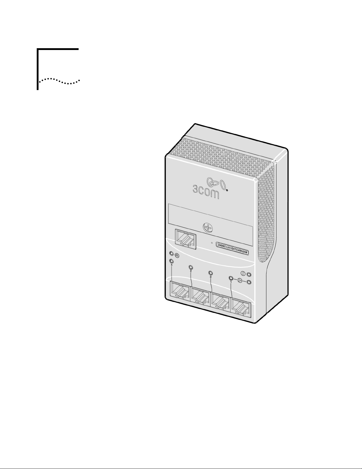
The 3Com NJ240FX IntelliJack is a 4-port, managed Ethernet switch that fits into
any standard electrical wall outlet or data port opening. It brings switching
capabilities for up to four networking devices, such as computer, printers, and
Voice Over IP (VoIP) telephones to a single fiber uplink to the network. All ports
feature 10/100 Mbps auto-negotiation. Power to the IntelliJack is provided
through a power supply internal to the unit.
Page 6

2 CHAPTER 1: INSTALLING THE NJ240FX INTELLIJACK
You can manage the NJ240FX using the included Central Configuration Manager.
You can also use a supported SNMP management console as you would with any
managed device on your network, but greater management and control is
available through the Configuration Manager software. Management features
include:
• Device discovery
• Port status (state, duplex, speed)
• Statistics
• Port control (port state, flow control, AutoMDI(X), frame rate limit)
• IPv4, IPv6 support
• 802.1P QoS/Priority
• 802.1Q compatible VLAN
• SNMPv3 support
• VLAN tag add/remove
• Firmware upgrade
• Rate limiting
• MAC filtering
• 802.1x port security
• User-configured VLAN IDs for management packets
• Port-based “calendar” function
Page 7
About the NJ240FX 3
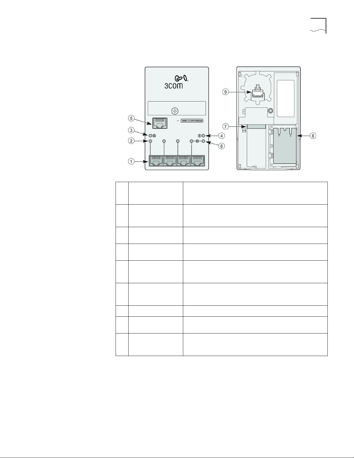
About the NJ240FX The following diagram shows the front and rear views of the IntelliJack:
1 RJ-45 switched PAN
(personal area
network) ports
2 Port LEDs and
corresponding port
numbers
3 LAN LED Indicates the link status of the LAN connection (fiber uplink).
4 Power LED Indicates IntelliJack power status (green). For more
5 Pass-through port
connector
6 Power-forwarding
LED
7 AC power socket The IntelliJack is powered by an internal power supply.
8 Fiber optic
transceiver
9 Pass-through port
cable
Four 10/100 Mbps auto-negotiation ports, which the
IntelliJack configures for 10 Mbps or 100 Mbps connections
automatically.
Indicate network link status of each of the four RJ-45 PAN
ports.
For more information, see “Checking the LEDs.”
information, see “Checking the LEDs.”
The pass-through port allows for connection to a separate
network. The data or voice traffic on this port does not flow
through the switch.
Lights when an IEEE 802.3af powered device is plugged into
Port #1 of the NJ240FX and power is being forwarded to that
device. For more information, see “Checking the LEDs.”
Connects the NJ240FX switched RJ-45ports to the fiber optics
network.
The pass-through port allows for connection to a separate
network. The data or voice traffic on this port does not flow
through the switch.
Page 8

4 CHAPTER 1: INSTALLING THE NJ240FX INTELLIJACK
Before You Begin Before you begin installation, register your product at: http://eSupport.3com.com.
The IntelliJack is available in three connector types: -LC (3CRNJ240FXLCTAA-75),
-SC (3CRNJ240FXSCTAA-75), and -ST (3CRNJ240FXSTTAA-75). Before you begin
the installation, familiarize yourself with the following items, which are included
with the IntelliJack:
• NJ240FX IntelliJack.
• Mounting plate
• Plastic cable housing tray
• Power cord
• Three screws
• Compact disc containing
n User Guide and additional informational documents.
n Configuration Manager software.
Planning the Installation Because the depth of some wall and cubicle openings differ, observe the following
requirements and recommendations before installing the IntelliJack:
• Ensure there is enough volume in the wall opening to accommodate fiber
cables.
• Ensure there is clearance around the unit for proper cooling.
• The NJ240FX has been designed for installation into wall or cubicle openings
that conform to NEMA standards.
• Make sure the distance between the back of the IntelliJack and the inside of
the wall or cubicle opening is at least 25mm to maintain an acceptable bend
radius on the cable.
• To ensure proper horizontal cabling functionality, adhere to the following
standards during installation:
n ANSI/TIA/EIA-568
Commercial Building Telecommunications Cabling Standard
n ANSI/TIA/EIA-569
Commercial Building Standard for Telecommunications Pathways and
Spaces
The network cabling at your site (from the wiring closet to the wall or cubicle
opening) may already be installed. If it is not, install the cabling following these
general guidelines.
NOTE: It is recommended that a professional cable installer perform these
procedures. Be sure to adhere to local safety and regulatory codes during the
cable installation.
Page 9

Mounting the IntelliJack 5
Setting up the Power
Mounting the IntelliJack
Supply
Power to the IntelliJack Switch NJ240FX is provided via AC power. It has an
internal power supply that can accept 100~240V AC power. A power connector
is supplied that can be securely plugged into the unit.
CAUTION: The supplied AC power cable is the only approved power cord that
can be used with the unit and is required to maintain proper strain relief of the
assembly and AC power cord.
Before connecting the IntelliJack to the network, verify that the existing network
cabling is connected to an active fiber port.
Instructions for unpacking and mounting the NJ240FX.
1 Remove the unit from its protective anti-static bag.
Page 10
6 CHAPTER 1: INSTALLING THE NJ240FX INTELLIJACK
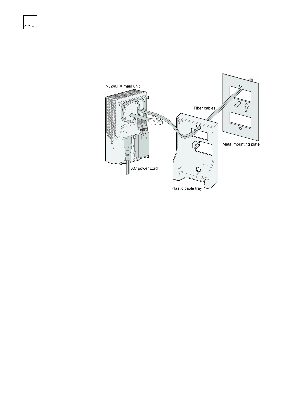
2 Remove any shipping tape from the unit and separate the metal plate from the
main unit. Separate the plastic housing cable tray from the main unit by sliding it
downward towards the four downstream ports and then away from the main
unit.
3 Route the two fiber cables through the rectangular opening directly above the UP
arrow indicator from the backside of the metal mounting plate (side opposite the
metal mounting post). Pull through enough cable to allow yourself room to
terminate the connections.
4 Route both fiber optic cables through the rectangular opening in the plastic
housing cable tray.
5 Attach both fiber optic cables to the fiber transceiver module located on the
backside of the main unit.
6 Route the two fiber cables around the cable management feature approximately
one turn until you end up in the area with no guide tabs.
7 Plug the supplied AC power cable into the mating plug on the backside of the
main housing.
Page 11
Mounting the IntelliJack 7
8 Reassemble the plastic cable tray to the main housing in the reverse order from
step 2.
NOTE: Care should be taken when reassembling the plastic cable tray to the
main housing so as not to damage the four installation guide hooks.
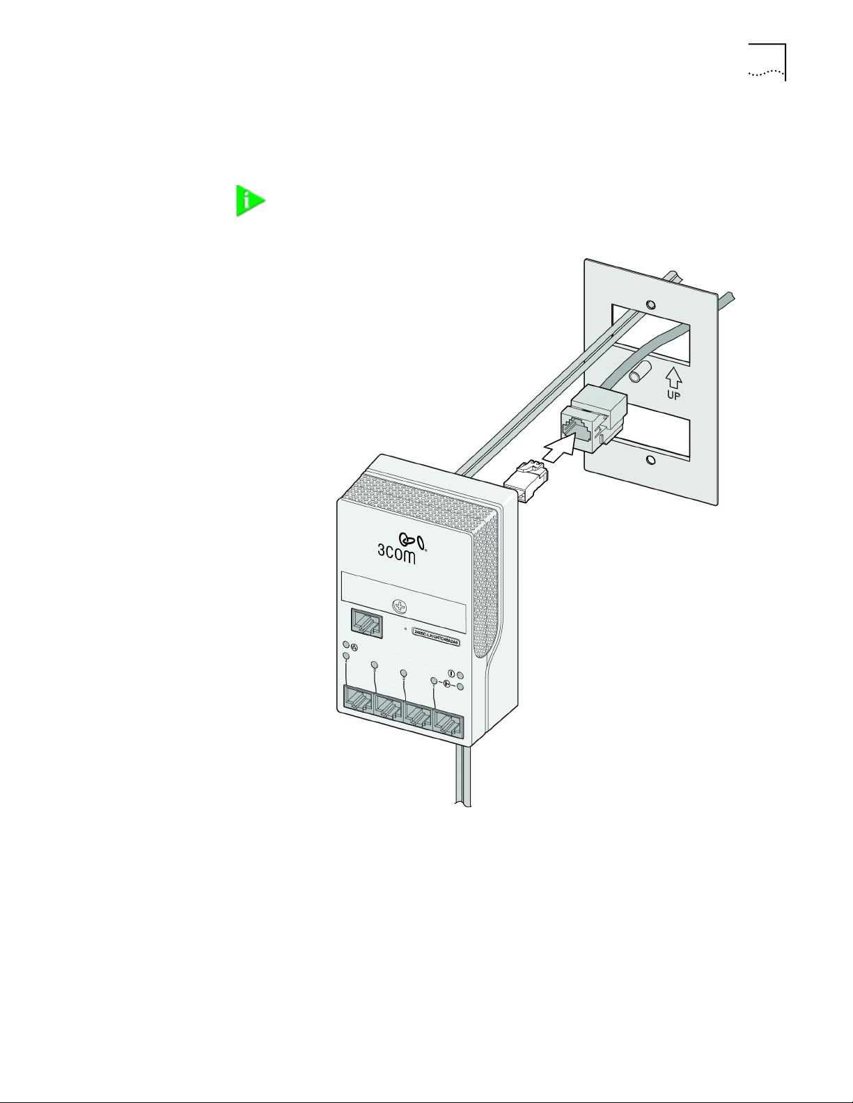
9 If the pass-thru feature is required, route the existing female RJ45 connector and
cable through the same rectangular opening in the metal mounting plate. Again
ensure you have allowed yourself enough room to terminate the connection.
10 If the pass-thru cable feature is required, connect the male RJ45 connector to the
existing female RJ45 connector.
11 Position the mounting plate over the NEMA box with the UP arrow indicator
facing upward for typical installations and secure into place using the two
supplied shorter pan head machine screws.
12 Push back all excess cabling into the NEMA box.
Page 12

8 CHAPTER 1: INSTALLING THE NJ240FX INTELLIJACK
13 Align the main housing mounting hole with the metal mounting boss on the
metal mounting plate and secure with the supplied long oval head machine screw.
NOTE: An access hole is provided for installations that require the supplied AC
power cord to be routed back into the NEMA box. Place the AC power cord
between the metal and plastic housing cable tray and route through the lower
rectangular opening in the metal mounting plate. Adjust cable for desired loop
length before securing in place.
Connecting Devices to the NJ240FX
Once the power source and the data source have been verified in good working
order and the IntelliJack has been installed and mounted, connect your
networking devices (such as computers, printers, IP phones, cameras, etc.) to the
IntelliJack.
The IntelliJack has two ways to connect devices:
1 RJ-45 Personal Area Network (PAN) Ports — any of the four switched ports on the
bottom of the IntelliJack. All ports feature 10/100 Mbps auto-negotiation, which
configures the NJ240FX IntelliJack for 10 Mbps or 100 Mbps connections automatically.
2 Pass-through port—a single pass-through port is provided that allows an additional
device to be connected to a separate network segment through the same IntelliJack.
The data or voice traffic that travels through the pass-through port, passes through
the IntelliJack without being switched.
Page 13
Checking the LEDs 9
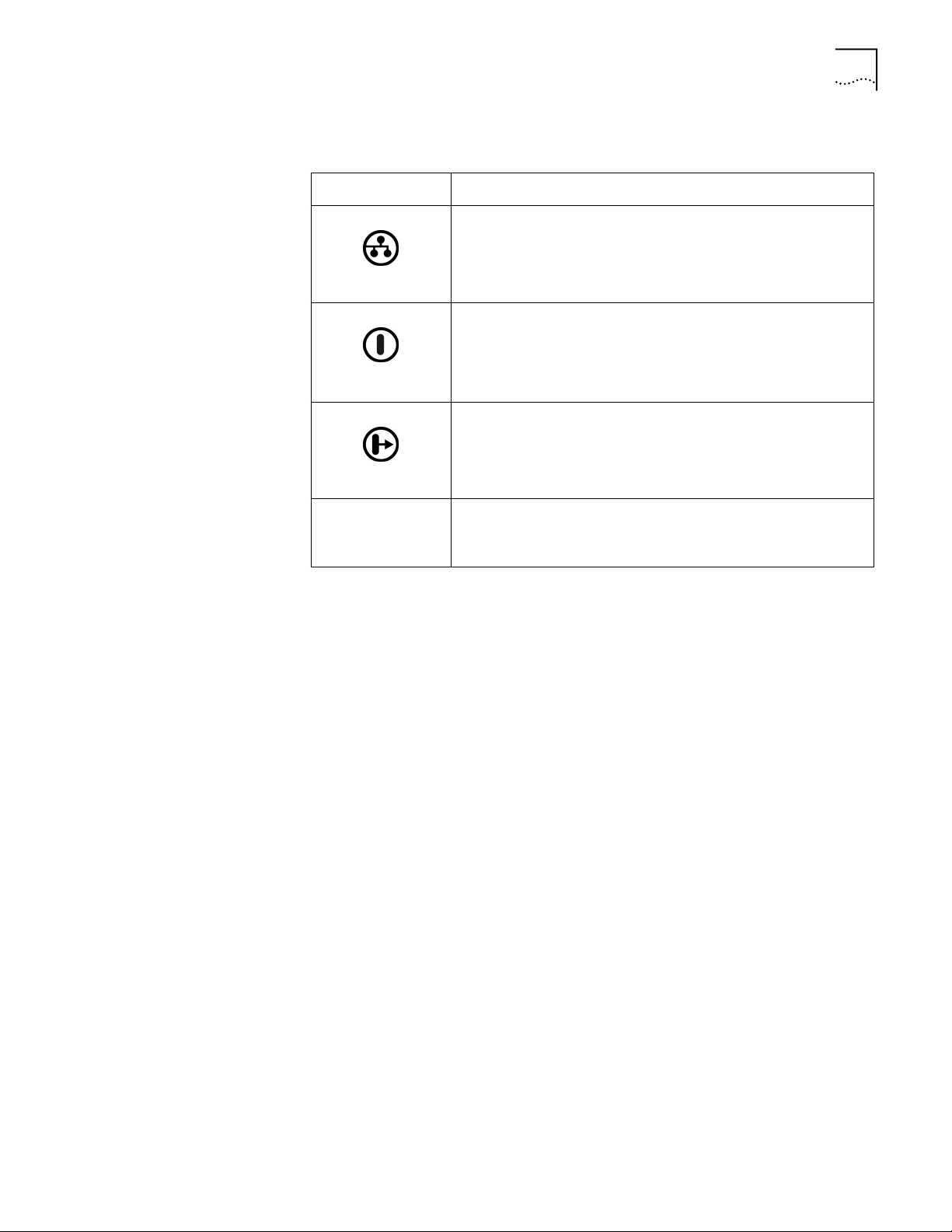
Checking the LEDs You can verify the NJ240FX installation by checking the LEDs.
LED Description
n On—the IntelliJack is connected to the network and a link has
been established.
n Off—there is no connection to the network.
(LAN)
n On—the IntelliJack switch is receiving power. When you first
connect power to the IntelliJack, there is a delay of
approximately 5 seconds. The power LED light blinks once or
twice before remaining solid on.
(Power)
(Power-forwarding)
n Off—the IntelliJack is not receiving power.
n On—the IntelliJack is connected to and is forwarding power to
an IEEE 802.3af-compliant device.
n Off—the IntelliJack is not connected to or is not forwarding
power to an IEEE 802.3af-compliant device.
4, 3, 2, 1
PAN PORTS
n On—a device is connected to the IntelliJack switch and a link has
been established.
n Off—no link has been established.
Page 14

10 CHAPTER 1: INSTALLING THE NJ240FX INTELLIJACK
Page 15

INSTALLING THE
2
System Requirements The machine you install the software on should meet the following requirements:
C
ONFIGURATION MANAGERS
Once you have installed the NJ240FX hardware, you need to configure it for use
on your particular network. To configure the NJ240FX, install the Local and
Central Configuration managers.
NOTE: You will use the Local Configuration Manager for initial configuration of
the NJ240FX on your network. It’s usually easiest if you load this software on a
laptop and use it to configure IntelliJacks as you install them.
The NJ240FX Central Configuration Manager is used for advanced
configuration and management of one or more NJ240FXs on your network.
This software should be installed on the machine you plan to use to manage
your NJ240FXs from a remote location—perhaps the same console you use for
SNMP management.
• Pentium processor
• Minimum of 15MB disk space
• Windows 2000, Windows XP Pro (required for IPv6 support), or Windows NT
4.0 with Service Pack 6 installed (While Windows 95 and Windows 98 are not
recommended operating systems for use with management platforms, the
Configuration Manager software may work with them.)
NOTE: The NJ240FX is designed with a dual mode IP stack. The unit can accept
and respond to commands over IPv4 or IPv6. The mode of operation of the
Central Configuration Manager will determine whether specific IPv4 or IPv6
parameters are displayed and can be configured by the CCM.
Page 16

12 CHAPTER 2: INSTALLING THE CONFIGURATION MANAGERS
Installing the Local and Central Configuration Managers
Run the following steps to install the Configuration Manager software:
1 Insert the NJ240FX CD into your Windows 2000, Windows XP Pro, or Windows
NT computer.
2 If your computer is configured to Auto-Play CDs, the installation will start
automatically. If not, double-click the setup.exe icon on the CD.
3 Click Next to continue.
4 Carefully read the license agreement. If you agree, select “I accept the terms in
the license agreement” and click Next to continue.
5 The installation will present Readme Information. This is also found in the
Readme.txt file on the installation CD. Please read the information and click Next
to continue.
6 Enter your user and organization names. You can also specify whether you want
the management programs to be available to just you or to anyone that may use
the computer you’re installing these applications on. Select the option you prefer
and click Next.
NOTE: If you have a previous version of the Central Configuration Manager
installed in another directory, you will lose access to any database or log files
that are stored there. Prior to completing the installation, you should copy these
files to the same directory into which you plan to install the configuration
software.
7 The program files will be installed in the directory C:\Program
Files\3Com\IntelliJack. If you want to change the location of the installation, click
Change. Otherwise click Next to accept the default location and continue.
8 Select a typical or custom setup and click Next. The Typical installation will install
both the Local Configuration Manager and the Central Configuration Manager on
your system. The Custom installation option lets you install just one of the
programs if you wish.
9 Review the settings you selected and click Install.
10 When the installation has completed, click the Finish button to close the
installation utility.
The installation utility will create two shortcut icons on the Desktop--one for the
Local Configuration Manager and one for the Central Configuration Manager.
You can also launch the programs from a program group you can access from the
Start menu. The program group folder is labeled 3Com IntelliJack and can be
found under the Programs menu.
Page 17
USING THE
3
Initializing the IntelliJack
LOCAL CONFIGURATION MANAGER
Once you have installed the NJ240FX hardware on your network and the Local
Configuration Manager software on your computer, you need to perform an
initial configuration of the IntelliJack.
1 The first step is to connect your computer to the NJ240FX that you are installing.
Attach an Ethernet cable from a computer running the Local Configuration
Manager software to any one of the four personal area network (PAN) ports on
the front of the NJ240FX.
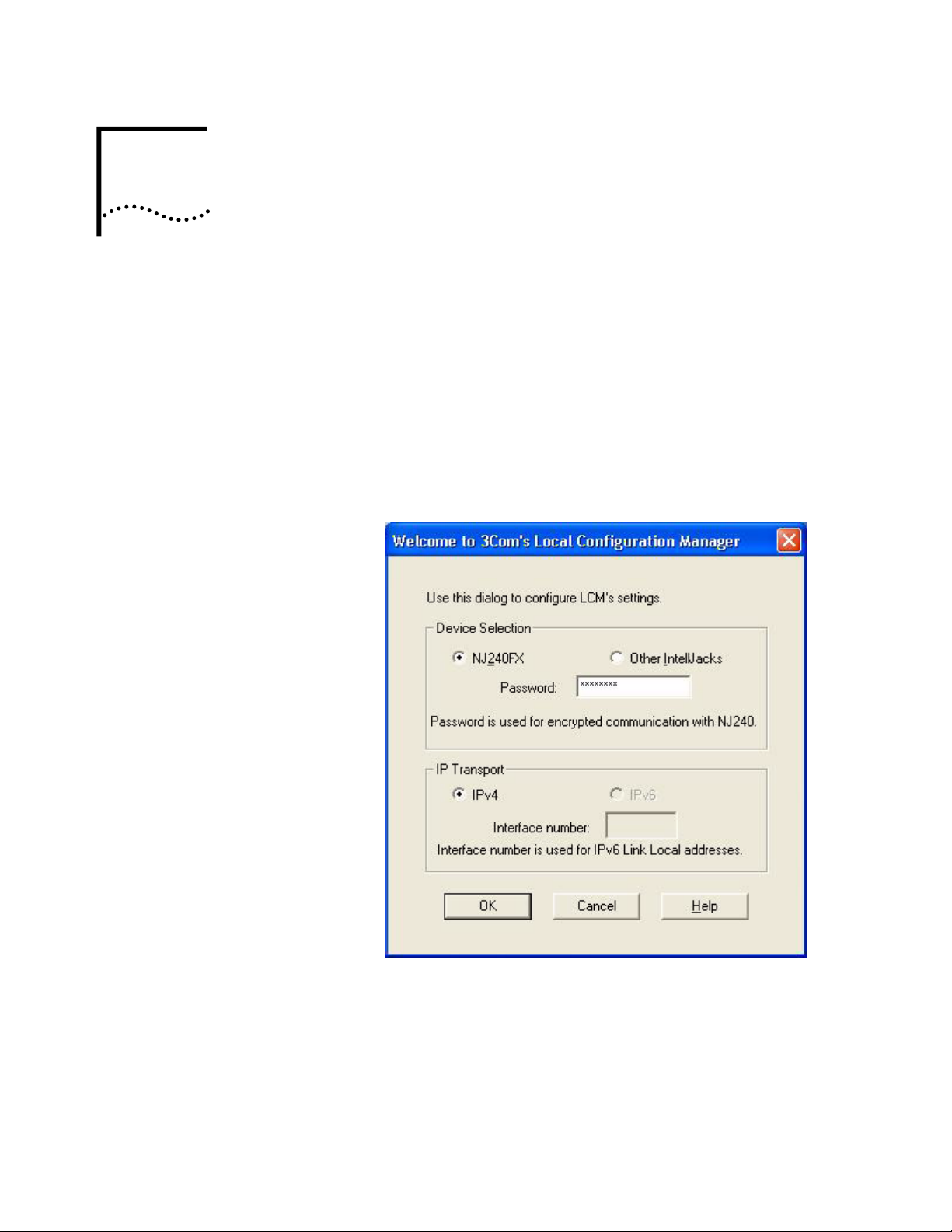
2 Click on the desktop shortcut icon labeled IJ Local Config Mgr to start the
program. When it launches, you will see a window like this:
3 Select the type of IntelliJack switch you would like to manage.
4 Enter the password for the device. The default password is “password” (without
the quotes). You will have the opportunity to specify a new password from within
this application.
5 Select the transport mode you are using to communicate on your network. The
IPv6 option will only be enabled if your operating system supports IPv6.
(IntelliJacks prior to NJ240FX do not support IPv6.) The Interface number
corresponds to the network interface in the computer running the LCM
Page 18
14 CHAPTER 3: USING THE LOCAL CONFIGURATION MANAGER
application. If this computer has more than one network interface, it may be
necessary to specify the correct interface number. You can use the Windows
IPCONFIG DOS command to assist you in determining the correct interface
number.
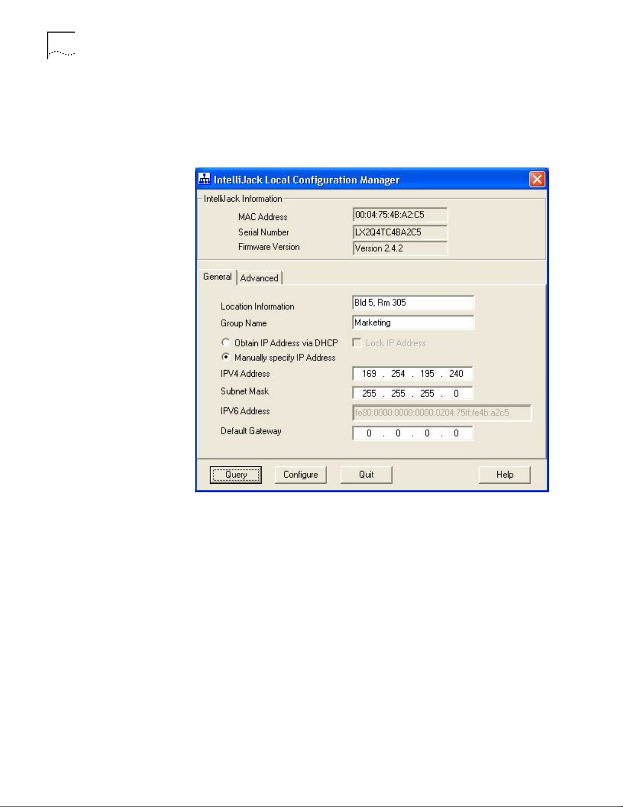
6 Click OK, and you will see this window:
7 The MAC address, Serial Number, and Firmware Version of the currently
connected NJ240FX will appear at the top of the window. If you connect to
another NJ240FX, you must click the Query button to refresh the window.
If you are not connected to any IntelliJacks, the MAC address field will display the
message Not Connected. If the Not Connected message appears, check your
connection to the IntelliJack and click the Query button.
8 Make sure the General tab is selected.
9 Enter Location Information for the NJ240FX you are currently configuring. This
field can help you and other network managers identify this IntelliJack in the
future. You may enter any information you like (up to 128 characters), but we
recommend that you enter a logical, easy to follow description, such as “Building
A, 3rd floor, room 315, West wall.”
10 Enter a Group Name for this IntelliJack. This can be any name you wish. With the
Central Configuration Manager, you can perform management tasks on all
IntelliJacks with the same group designation.
11 Select the method the NJ240FX should use to obtain an IP address. The NJ240FX
can either get an IP address from an existing DHCP server on your network, or you
can specify an address. If you elect to specify your own address, you should enter
Page 19

Setting Advanced Options 15
the IP Address, Subnet Mask, and Default Gateway information in the appropriate
fields.
NOTE: By default, the NJ240FX is configured to automatically obtain an IP
address from a DHCP server. If no DHCP server exists, or if the NJ240FX cannot
obtain an IP address, it will default back to its previously configured static IP
address. If it had previously been assigned an IP address, it will default to that
one. If it did not, it will default to the static IP address of 192.168.1.252.
12 If you wish, check the box next to Lock IP Address. Selecting this option will
ensure that the IntelliJack will always use a particular address.
WARNING: If you lock an IP address and reserve it for this IntelliJack, make sure
you configure your DHCP server so it won’t distribute that address to other
devices.
13 Click the Configure button. Any changes you specify are sent to the NJ240FX and
will become effective immediately.
Setting Advanced Options
Those are the only steps required to initialize your NJ240FX.
If you want to change the default password of the NJ240FX or change SNMP
community strings, you can configure these settings from either the Local
Configuration Manager or the Central Configuration Manager (covered in the
next chapter). In the Local Configuration Manager, both settings are found under
the Advanced tab.
Page 20
16 CHAPTER 3: USING THE LOCAL CONFIGURATION MANAGER
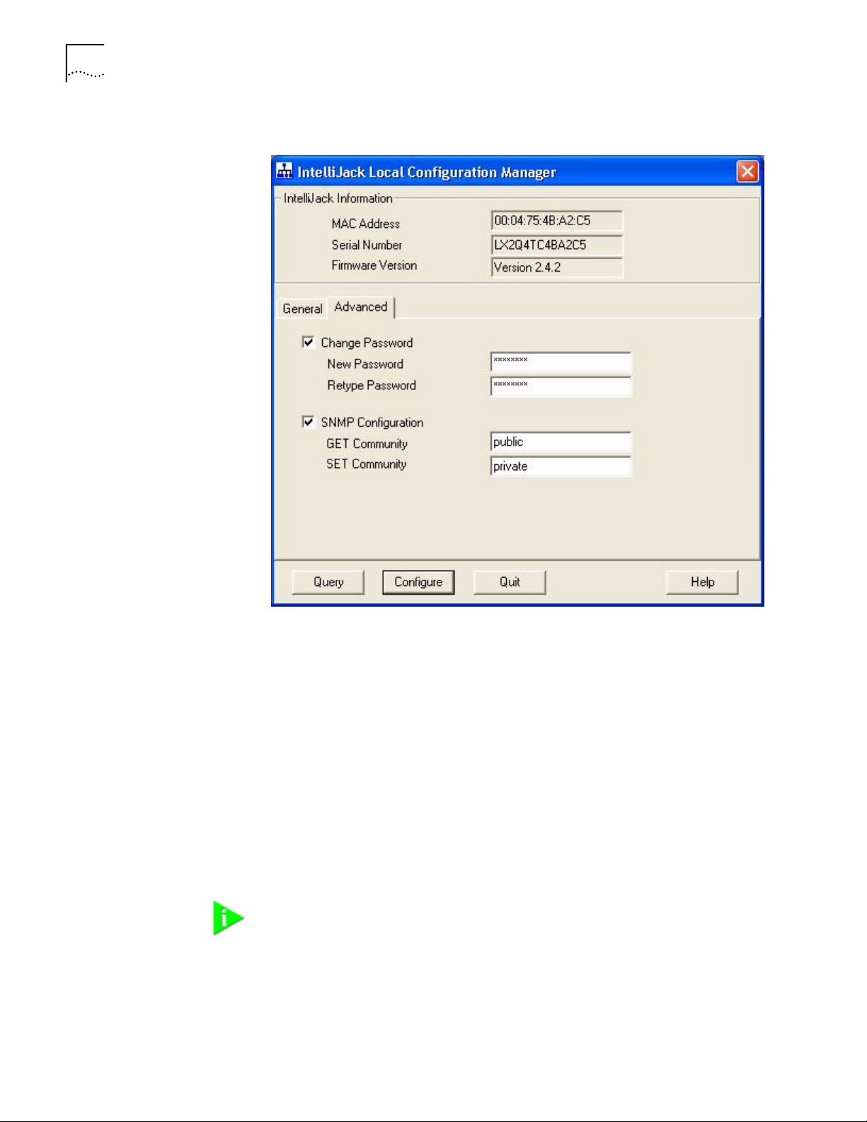
1 Select the Advanced tab on the IntelliJack Local Configuration Manager window.
2 To change the IntelliJack’s configuration password, click on the box next to
Change Password. Then enter the new password in both password fields. (You
must enter the password twice to ensure you type it correctly.) The password you
select can be any combination of letters and numbers between 8 and 32
characters.
3 To configure the NJ240FX for management with an SNMP console, select the
SNMP Configuration box. Enter the GET Community string and SET Community
string in the appropriate fields. Each field lets you enter any combination of letters
and numbers up to 32 characters.
Note that this only applies to SNMP v1. If you are using SNMP v3, you will need to
create SNMP profiles using the Central Configuration Manager.
4 Click the Configure button. The changes are sent to the NJ240FX and will become
effective immediately.
NOTE: You should change the password to ensure that no one else can
re-configure your system. Make sure you remember the new password you set.
If you forget the new password, you will not be able to perform any
other configuration tasks unless you send the device back to 3Com.
Page 21

USING THE
4
Discovering IntelliJacks on Your Network
CENTRAL CONFIGURATION MANAGER
You should use the Local Configuration Manager to initialize each of the
IntelliJacks installed on your network. Once you have completed that step, you can
manage all of them with the Central Configuration Manager.
Install this program on any computer on your network you want to use as a
central management console (See chapter 2, “Installing the Configuration
Managers” for help). You can use the same machine that has your SNMP-based
management platform. The Central Configuration Manager will be able to
configure and manage all of the IntelliJacks that reside on your network.
We recommend that you keep the Central Configuration Manager (CCM) running
on your machine. Information such as traps and alerts are sent to the CCM on a
periodic basis. If you shut off the machine or close the configuration manager, you
will not be able to receive this information.
In order to manage the IntelliJacks on your network, the Central Configuration
Manager needs to include them in its database. The easiest way to add new
IntelliJacks to the database is to use the device discovery tool included in the
Central Configuration Manager.
Page 22
18 CHAPTER 4: USING THE CENTRAL CONFIGURATION MANAGER
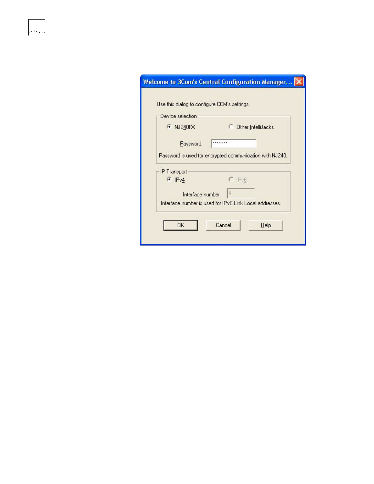
1 When you launch the Central Configuration Manager, you will see a welcome
window like this one:
You should select the type of IntelliJack switch you would like to manage with the
CCM software. If you are managing an NJ240FX IntelliJack, then enter the
password (“password” by default) you specified when you first installed the
IntelliJack switch. Entering a password is not required to communicate with other
IntelliJacks.
Next select the IP transport you will use for communication on your network. The
IPv6 option will only be enabled your operating system supports IPv6. (IntelliJacks
prior to NJ240FX do not support IPv6.)
The interface number corresponds to the network interface in the computer
running the CCM application. If this computer has more than one network
interface, it may be necessary to specify the correct interface number. You can use
the Windows IPCONFIG DOS command to assist you in determining the correct
interface number.
The CCM can only manage one type of IntelliJack switch at a time (i.e., either
NJ240FX or NJ220). To switch between managing these two types of IntelliJacks
without exiting the CCM, select CCM Settings from the View menu to display the
CCM session configuration window. From here you can make the necessary
changes. If you decide to change the type of IntelliJack that is being managed, you
must re-discover the IntelliJacks on your network. If you want to change the IP
transport used, you must restart the CCM.
Page 23
Discovering IntelliJacks on Your Network 19
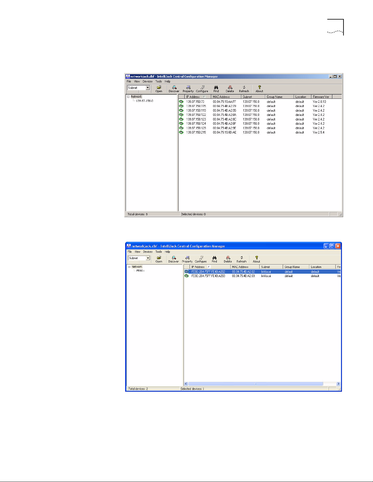
2 Click OK, and you will see a window similar to this one if the CCM is operating in
IPv4 mode and you have previously discovered IntelliJacks:
If the CCM is operating in IPv6 mode, it will look like this:
Page 24

20 CHAPTER 4: USING THE CENTRAL CONFIGURATION MANAGER
3 Select Discovery from the Devices menu or click the Discover button on the
toolbar to load the following window (this window will load automatically the first
time you run the Central Configuration Manager).
If the CCM is operating in IPv6 mode, the window will look like this:
Page 25

Discovering IntelliJacks on Your Network 21
NOTE: The default subnets are the ones your machine is connected to.
4 You can discover new devices based on a specific subnet or on a specific range of
IP addresses.
a To discover devices by subnet, select that option on the screen. Click the Add
button to add a new subnet to the discovery list. The following box will appear:
Fill in the Subnet and Mask fields and click OK.
or
b To discover devices within a certain IP range, select that option on the screen
and complete the From and To fields.
5 If the box next to “Delete all devices in the existing list” is checked, the discovery
process will replace all of the devices in your current database with the new
devices it discovers. If unchecked, the discovery process will add newly discovered
devices to the current database.
6 Click OK to start the discovery process.
The device discovery tool will return the following information from the IntelliJacks
on your network:
• IP address
• MAC address
• Subnet address
• Group name
• Location information
• Firmware version
You can sort this information in ascending or descending order.
Page 26

22 CHAPTER 4: USING THE CENTRAL CONFIGURATION MANAGER
NOTE: Discovered devices are automatically added to the default database.
This default database will open automatically when you launch the Central
Configuration Manager. If you like, you can keep several database files, each
with its own list of devices. For example, you may want a separate database for
each subnet you manage. To save a database file or open another database file,
select the Open Database or Save Database As option from the File menu.
You can view discovered devices many ways. On the left side of the toolbar, you
can see a drop down box with options for either Subnet, Firmware Ver, or Group
Name. The option you select in this box determines how the views are displayed in
the left pane of the window.
When Subnet is selected (the default option), you will see a list of IP subnets to
choose from. Selecting Network will show all of the discovered devices in the
database. If you select a particular subnet, only the devices in that subnet will be
displayed.
When Firmware Ver is selected, you will see a list of the different firmware
versions loaded on the devices. This view is particularly useful if you want to select
only the devices with an old firmware version so you can perform an upgrade.
Viewing Device Properties
When you select Group Name from the drop down list, the Central Configuration
Manager will present a list of the different group names you have specified.
Once the database is populated with IntelliJacks on your network, you can begin
to manage those devices. The main window of the Central Configuration
Manager shows a list of devices in the current database with the information
retrieved during the discovery process. You can view and configure the properties
for a single NJ240FX using this window. To configure multiple devices at one
time, see “Changing Device Configuration.” To get more detailed information
about a device, you should check its properties.
The process for configuring one or more IntelliJacks is the same. You choose the
changes or configurations you wish to make by selecting them from the various
tabs in Device Properties (for changes to a single IntelliJack) or Configure (for
single or multiple IntelliJacks). When you have finished making changes, click
“Apply” or “OK”. You will be asked for your password. The configuration
changes will not be made to the IntelliJack until your password has been correctly
entered.
1 Select an IntelliJack from the devices list.
Page 27

Viewing Device Properties 23
2 Select Property from the Devices menu or from the toolbar. You can also open this
window by right-clicking your mouse and selecting Property.
Page 28

24 CHAPTER 4: USING THE CENTRAL CONFIGURATION MANAGER
If the CCM is operating in IPv6 mode, the screen will look like this:
General Tab
3 With the General tab selected, you can view and edit information about the
device such as the IP address, subnet mask, default gateway, and whether it uses
a static IP address or gets its address from a DHCP server. You can also view and
edit the IntelliJack’s Group Name and Location.
4 Click Apply to save any changes you make to the fields in this window.
Port Information
5 In the middle of this window you’ll see information about each of the four PAN
ports on the front of the IntelliJack. You can check to see if the port is Enabled or
Disabled, if there is a network link, its priority, whether or not it’s part of a virtual
network (VLAN), its 802.1x security setting, if it’s running at half or full duplex,
and what speed it’s set for.
Page 29

Viewing Device Properties 25
You can double-click on any of the ports to find out more information or
configure that particular port.
Click OK to save your changes or Cancel to discard them.
Product Information
6 Under the Product Information box, you can see the current firmware version of
the IntelliJack, the Product Name, and the Serial Number.
Page 30
26 CHAPTER 4: USING THE CENTRAL CONFIGURATION MANAGER
Hardware Settings Tab
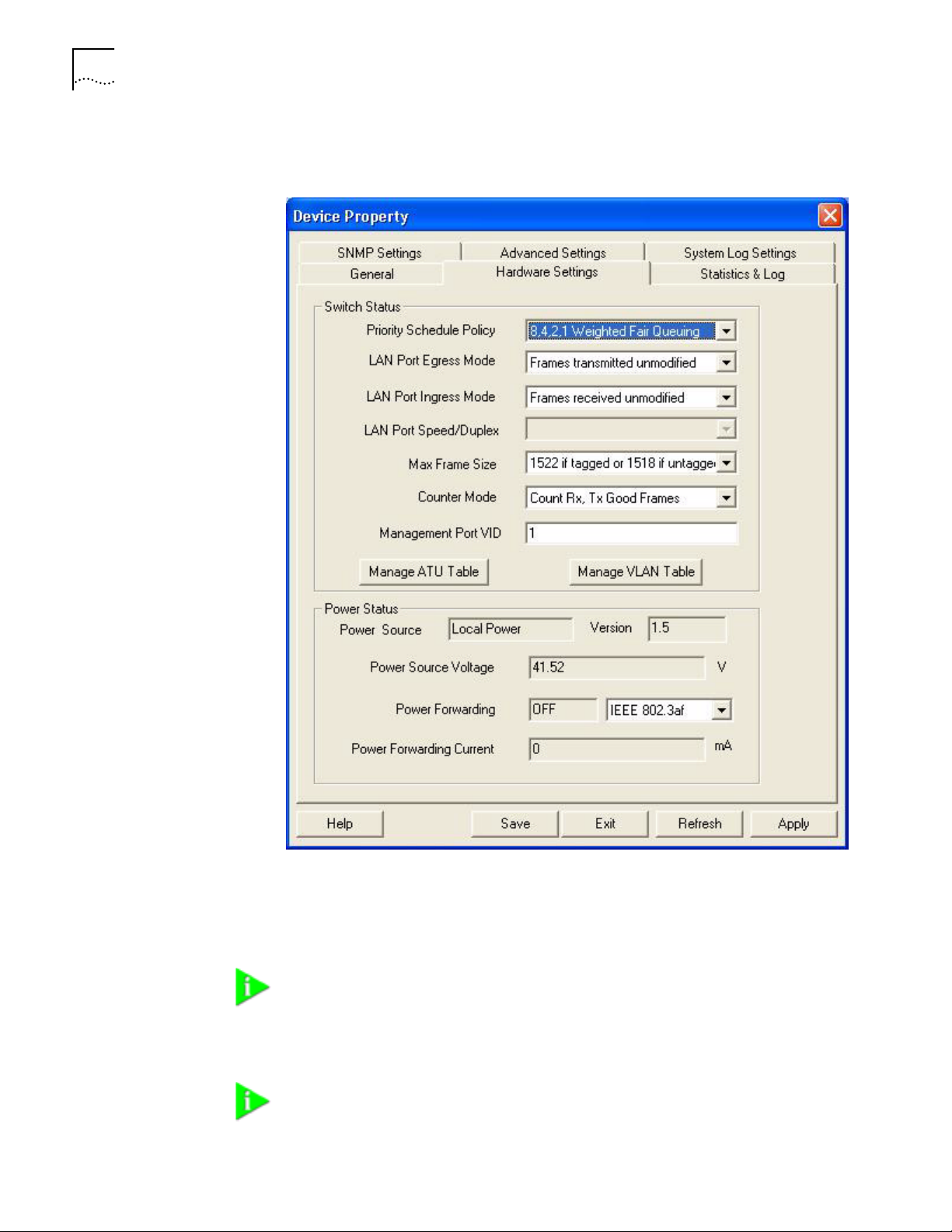
7 Click on the Hardware Settings tab to view status information about the switch.
Several fields in this window can be edited, a few cannot. You can change the
values of the fields with drop-down lists: Priority Schedule Policy, LAN Port Egress
Mode, LAN Port Ingress Mode, LAN Port Speed/Duplex, Max Frame Size, Counter
Mode, and Power Forwarding.
NOTE: The LAN Port Speed/Duplex field will be grayed out for the NJ240FX
because you are unable to configure the speed and duplex of a fiber
connection.
NOTE: For help determining the best configuration options for your system, see
the Changing Device Configuration section.
Page 31

Viewing Device Properties 27
8 Simply select the value you wish to change from the drop-down list of options.
NOTE: You can click Apply at any time to save the changes you have made. But
be sure to click Apply after you have finished making all your changes.
9 Click the Manage ATU Table button to make changes to the NJ240FX’s ATU table.
The screen you see allows you to display all MAC addresses that have been
plugged into that IntelliJack or just the ones that you have “locked down” to it.
You can refresh the list, add MAC addresses to it, edit existing ones or delete
entries in the ATU table.
The Address Translation Unit (ATU) performs MAC address searching, learning,
and aging functions for all ports of the IntelliJack. By default, the ATU table allows
a total of 512 entries and an aging time is 304 seconds for each entry. These
settings (ATU, ATU aging time, and ATU entries) are fixed and not editable.
The IntelliJack lets you manage its ATU table. You may want to know which MAC
addresses have been connected to a particular IntelliJack. You may want to
associate a MAC address with selected ports, so the unselected ports will not
receive frames from this MAC address. You may want to set a certain priority
level to the frames associated with the MAC address. Finally, you may want to
lock down a MAC address so that it is never dropped from the ATU table. This
last operation is referred to as MAC address filtering and you can lock down up to
32 MAC addresses into the ATU. All of these configurations are handled through
the Properties page, since an ATU table is related to a specific IntelliJack.
Page 32

28 CHAPTER 4: USING THE CENTRAL CONFIGURATION MANAGER
10 The IntelliJack also lets you manage its VLAN table. To access the VLAN table, click
on the Manage VLAN Table button. The screen you see allows you to display all
the VIDs that have been assigned to that IntelliJack.
You can refresh the list of VIDs or add to it. You can edit existing VLAN settings,
tagging schemes and port associations by clicking the Edit button.
The VLAN table is a record of the VLAN settings which have been configured for a
particular IntelliJack. You may want to know which ports have been assigned a
VLAN ID (VID), whether packets are tagged or untagged and whether the ports
are associated with one another. All of these configurations are handled through
the Properties page, since a VLAN table is related to a specific IntelliJack.
Page 33

Statistics & Log Tab
Viewing Device Properties 29
11 Click on the Statistics & Log tab.
From this view you can see statistics about the number of good or bad packets
each port has received and transmitted, based on how you have configured the
Counter Mode setting.
The bottom half of the window shows Remote MONitoring (RMON) counters for
the LAN port and each of the four PAN ports on the IntelliJack. RMON counters
are extensions to the Simple Network Management Protocol (SNMP) that provide
comprehensive network monitoring capabilities (see appendix C for detailed
information).
12 To load the counter information from the IntelliJack, click the Read button.
This window lets you monitor the traffic through your network by displaying
statistics for many types of packets. The left side shows Ingress counters for
packets coming into the IntelliJack’s port. The right side shows Egress counters for
packets leaving the port.
Page 34

30 CHAPTER 4: USING THE CENTRAL CONFIGURATION MANAGER
You can reset all counters to zero by clicking Clear.
To save device data to a log file, click Get Device Log. This will prompt you for a
filename and location to save the log file.
NOTE: The device log records information regarding watch-dog timer errors or
other abnormalities. If, for example, the IntelliJack has unexpectedly rebooted,
the event will be recorded in the device log. 3Com Customer Support can use
information in the device log to help with troubleshooting. We recommend
that you do not attempt to use this log.
SNMP Settings Tab
13 Click on the SNMP Settings tab to see the following window:
14 You can view and edit the SNMP Community String settings and Trap settings for
this particular NJ240FX.
15 You can select whether you want to use only SNMP v3 or v2c and v1 as well.
Page 35

Viewing Device Properties 31
16 To edit a Trap Destination, enter the IP address of your SNMP management
console in the field. This eliminates the need to build a Trap Destination Table via a
Management Information Database (MIB) browser.
In order for an SNMP Management Tool to communicate with an NJ240FX in
SNMPv3 mode, you will first need to create an SNMPv3 Profile on the NJ240FX.
Please note that, as with passwords, these stored profiles will not be displayed, so
it is advised that you make note of the details of your saved profiles. You can store
up to 14 SNMPv3 User Profiles on your NJ240FX, and you can add, modify or
delete a profile.
To create a profile, enter the desired User Name, with the appropriate
Authentication and Privacy Protocol, and passwords if required. These protocols
and passwords are not required, but must match the corresponding settings on
the SNMP Management Tool you wish to use for communication with the
IntelliJack. Once you have selected the appropriate options for the profile, you can
either save it as a new profile by selecting Apply. You can also modify the settings
of a profile previously stored with the specified User name, by selecting the Edit
operation, and then selecting Apply.
You can use the Delete option to create space in the database, by deleting
previously stored profiles. To do this, you enter the name of the profile and select
Delete Operation, followed by Apply. To delete a profile, you only need to enter
the profile name, you do not need to enter any other parameters.
Page 36

32 CHAPTER 4: USING THE CENTRAL CONFIGURATION MANAGER
Advanced Settings Tab
17 Click on the Advanced Settings tab to see the following window:
18 You can view the Event Alert Level and 802.1X Settings configured for this
particular NJ240FX. 802.1X is a security protocol for LANs that relies on the
Extensible Authentication Protocol (EAP) to pass messages to RADIUS
authentication servers.
NOTE: For help configuring SNMP and 802.1X settings for your system, see the
Changing Device Configuration section.
Page 37

Viewing Device Properties 33
Different Alert Levels notify you of specific events happening with the IntelliJack.
Each level above 0 provides different types of event alerts as described below:
Alert Level Notifying Event
Level 0: Disable all alert messages None
Level 1: Allow critical alerts Device Power Failure/Reboot
Abnormal Reboot
IP Address Change
Level 2: Allow standard alerts Device Power Failure/Reboot
Abnormal Reboot
IP Address Change
Unauthorized Access
Level 3: Allow all alerts Device Power Failure/Reboot
Abnormal Reboot
IP Address Change
Unauthorized Access
Normal Reboot
NBX phone plugged in
NBX phone removed
Next to the Event Alert Level field is a box labeled Receive Alert. If you are running
the Central Configuration Manager on more than one machine in your
organization, the Receive Alert box will only be active for the last CCM that
discovered the device. The box will be grayed out on the CCMs of all other
machines.
Page 38

34 CHAPTER 4: USING THE CENTRAL CONFIGURATION MANAGER
System Log Settings Tab
19 Click on the System Log Settings tab to display the following window:
20 If the CCM is operating in IPv6 mode, then the screen will present an IPv6
formatted address field. The NJ240FX will store only one set of System Log server
addresses, either an IPv4 set or an IPv6 set. The last type of address that was
written to the unit is what will be stored.
NOTE: You are able to see the IPv4 type addresses only when the CCM is
operating in IPv4 mode. Similarly, the IPv6 addresses can only be seen when the
CCM is operating in IPv6 mode.
21 Click Apply to save any changes you make, and a configuration summary dialog
box will appear. Verify the information and click OK.
22 Click Exit to close the Device Property window.
Page 39

Changing Device Configuration 35
Changing Device Configuration
Many of the properties that you can view from the Device Property windows can
be changed from the Device Configuration window. Here’s how to use this
feature:
1 Select one or more IntelliJacks from the devices list.
NOTE: It is possible to configure multiple IntelliJacks at the same time.
2 Select Configuration from the Devices menu or the toolbar, or right click on a
device and select Configuration from the pop-up menu.
NOTE: To make configuration changes to a IntelliJack from the Central
Configuration Manager, the NJ240FX must be part of the device database. See
the section on Discovering NJ240FX Devices on Your Network for information
about including new devices in the database.
You must also be able to communicate with the device from your workstation
in order to configure it. If you can’t communicate with the device at this time,
you will receive an error message.
Page 40

36 CHAPTER 4: USING THE CENTRAL CONFIGURATION MANAGER
This window has six tabs across the top--General Configuration, Priority & VLAN
Configuration, Security Configuration, SNMP Configuration, Advanced
Configuration, and System Log Settings. Check the box next to any setting you
want to change from within these five areas.
The bottom of the window has buttons labeled Load and Save. The Save
operation lets you save an IntelliJack configuration profile. You can then use the
Load button to apply the configuration profile to one or more IntelliJacks.
If you wanted to send a single configuration to one or more IntelliJacks, you
would make the configuration changes in this window and click Save. Then you
could select a list of IntelliJacks from the main Configuration Manager window
and click Load, choose the file, and click OK. This would send the configuration to
all of the IntelliJacks that you selected.
General Configuration
3 Make sure the General Configuration tab is selected.
Identification Settings
4 To change or set the Group Name, check the box next to that field. You can set a
Group Name to anything you want, up to 128 characters.
5 Change or set the Location Name by checking the box next to that field and
entering up to 128 characters.
6 Configure the DHCP setting to the desired state.
Hardware Settings
7 Change the Port state of any of the IntelliJack’s ports by selecting the Port tab and
checking the box next to the characteristic you want to modify. Then select a
value from the drop list.
Forwarding (Enable) is the default setting for the Port State. The other option is
Blocking (Disable). Forwarding (Enable) allows traffic to pass through the
individual ports. By setting the Port State to Blocking (Disable), you can block any
traffic from passing.
You may want to set the Port State to Blocking (Disable) when you want to restrict
access to your LAN at the location where the IntelliJack is installed. This might be
an appropriate option in a public use area such as a lobby, conference room, or
classroom. Using the Calendar function, you can schedule the Port State for
Forwarding (Enable) or Blocking (Disable) at specified times and dates.
8 To change the Link State setting, click the box and select an option from the drop
list.
Auto Negotiation is the default setting and the de facto setting for most network
equipment because it is the most flexible option. It automatically configures a
networked device based on the speed and duplex of the upstream device it is
plugged into. This is especially useful when you do not know the configuration
(speed/duplex) of all devices connected to the network.
Be advised, however, that not all network interface cards (NICs) use the standard
auto-negotiation algorithm, and it may be necessary to force the speed and
duplex of the PAN port to match the speed and duplex of the attached NIC.
9 The next two settings apply not to a specific port, but to the IntelliJack as a whole.
By default, the Central Configuration Manager will display a count of good
Page 41

Changing Device Configuration 37
transmissions in the Property window because it is unlikely that the IntelliJack will
drop any Ethernet Packets.
If you believe that the IntelliJack is dropping Ethernet packets, you may want to
configure the Counter Mode to count received errors (Rx Errors) and transmission
collisions (Tx Collisions). This will give you a good sense of whether packets are
actually being dropped.
10 To change the Power Forwarding setting, click the box and select an option from
the drop list.
IEEE 802.3af is the recognized standard for Power over Ethernet (PoE) and the
default setting. More and more network devices that are POE capable are
adhering to this standard.
The IntelliJack’s Power over Ethernet capability also lets you forward power to a
standards-compliant device plugged into Port 1 of the NJ240FX. The default
setting of the NJ240FX is auto-detect. We recommend that you keep this setting
as part of your configuration to ensure that power will only be forwarded to
devices capable of receiving it.
The IEEE802.3af standard requires a powered device to present a signature to the
power sourcing equipment. The power sourcing equipment will check this
signature and will only apply power to the line when it sees the correct signature.
If you want to ensure that power will not be forwarded at all, however, you could
select Force power OFF to any device connected to Port 1.
Select Force power ON if you always want to apply power to any device plugged
into Port 1. This option would let you power devices plugged into Port 1 that do
not have the signature required by IEEE802.3af-compliant power sourcing
equipment.
WARNING: By forcing power ON, you may damage equipment that is
inadvertently plugged into Port 1, such as a device that is not designed to
handle 48V.
Page 42

38 CHAPTER 4: USING THE CENTRAL CONFIGURATION MANAGER
Priority & VLAN
Configuration
11 Click the Priority & VLAN Configuration tab along the top of the Device
Configuration window to view these settings:
Port Based Settings
12 To change the Port Based Settings, first select the Port’s tab you want to make the
changes to.
13 To change the Look-up Scheme from the default of Use Both, click the box and
select an option from the drop list.
Both the Use IEEE 802.1p Traffic Class Field and Use IP TOS, DiffServ fields look-up
schemes examine Ethernet packets to determine their prioritization. The former
looks at one portion of the packet, effectively making it a Layer 2 tool. The latter
looks at a different part of the packet, effectively making it a Layer 3 tool.
The Look-up Scheme is part of the prioritization of Ethernet packets. Prioritization
determines which packets clear the buffer first. If you didn’t care about the
prioritization of packets, you would choose None. If you wanted to prioritize voice
packets on Port 1, for example, you would choose another option.
Page 43

Changing Device Configuration 39
14 The default setting for the Default Priority Level is 802.1p Priority 0 or 1. You can
change this setting to Priority 2 or 3, Priority 4 or 5, or Priority 6 or 7.
The IntelliJack has four traffic queues with two priorities per queue. The lowest
numbers (0 and 1) have the lowest priority. The default priority traffic is called
“Best Effort” and serves as a baseline priority for all standard Ethernet traffic.
If you want to assign a higher priority to traffic on a particular port (voice traffic,
for instance), you can do so. The higher the number the higher the priority (Priority
6 or 7 is the highest). The IntelliJack will send higher priority traffic ahead of lower
priority traffic to improve the quality and throughput from that particular port.
15 You can associate any of the four ports with any other ports on this IntelliJack to
form a VLAN group. You can specify the tag schemes for the VLAN you create.
You can set the VLAN ID (VID) field to any number between 0 and 4094. The
default setting is 1, which is the common practice. If all equipment is set at VID 1,
you can communicate across all ports.
Since VLANs are used to separate network traffic to make it more manageable
and secure, you would change the VID of the individual ports to meet the needs
of your network.
In a classroom setting, for example, you may want the teacher to be on a separate
VLAN than the students. You could assign VID 10 to Port 1 of the IntelliJack for
the teacher and VID 20 to the other ports.
NOTE: The VID of a port must match the upstream switch VLAN assignments. If
the IntelliJack’s VID assignments do not match the upstream switch and “add a
VLAN tag” is set in the Egress rule, then the traffic that passes from the
IntelliJack to the LAN will be dropped at the upstream switch port.
16 To change the VLAN mode setting, click the box and select an option from the
drop list. You can choose to Disable the VLAN. In this mode, ingress frames are
forwarded through default switching rules.
You can also choose Enable unrestricted VLAN. In this mode, the port is associated
with the current VLAN ID you have set. Frames ingressed into this port without a
VLAN tag or with the same VLAN ID are forwarded within the VLAN. Frames with
a different VLAN ID are forwarded according to default switching rules (i.e., based
on the destination MAC address). Management packets are able to pass through
this port on this setting.
Finally, you can choose Enable restricted VLAN. In this mode, the port is associated
with the current VLAN ID you have set. All frames ingressed into this port are
forwarded within the same VLAN, and management packets are blocked on this
port.
Other Priority & VLAN Settings
17 Click the box and select from the drop list to change the Priority Schedule Policy.
The default setting is 8,4,2,1 weighted fair queuing scheme.
8,4,2,1 refers to the number of bytes removed from the IntelliJack’s buffer. 8
bytes of the highest priority traffic are removed from the buffer first, then 4 bytes
from the second most important, 2 bytes from the third, etc. This is the most
common priority scheme because it ensures that important traffic is prioritized but
still allows traffic flow for all ports.
Page 44

40 CHAPTER 4: USING THE CENTRAL CONFIGURATION MANAGER
In a strict priority scheme (the setting’s other option), all highest priority traffic will
be removed from the buffer. After it is removed, the next priority traffic type
would be removed, and so on. This ensures that the most important or time
critical data is passed first, but it could potentially slow traffic from other ports.
18 You can change the Outgoing (to LAN) tag scheme for the IntelliJack. By default,
frames are transmitted unmodified. This setting ensures that you will not risk
losing communication with upstream switches due to misaligned VLAN IDs (VIDs).
If you want to configure traffic from a port on the IntelliJack, you can add a tag to
the frame. This lets you separate traffic into different VLANs.
19 You can also change the Incoming (from LAN) tag scheme. By default, all frames
are received unmodified. By receiving frames unmodified, you will not risk losing
communication between upstream switches and the devices connected to the
IntelliJack due to misaligned VIDs.
If an upstream switch is sending a tagged packet but the device connected to one
of the IntelliJack ports does not need the tag information, you can remove the tag.
20 It is common practice to set the VLAN ID (VID) of the management port to VID 1,
and this is the default value.
The management port is the port through which all commands to and from the
IntelliJack are communicated. You may want to separate management traffic from
other network traffic by assigning the Management Port of the IntelliJack to a
different VID. You should make sure that the VID for the management port of the
IntelliJack is the same as the VID for management ports of upstream devices.
Page 45

Security Configuration
Changing Device Configuration 41
21 Select the Security Configuration tab to set the security options of the IntelliJack.
Password
22 You can change the device password (the default password is “password”), and
either enable or disable local configuration.
NOTE: You should change the password to ensure that no one else can
re-configure your system. Make sure you remember the new password you set.
If you forget the new password, you will not be able to perform any
other configuration tasks unless you send the device back to 3Com.
802.1X
23 To change 802.1X settings for a specific port, select that port’s tab and make the
changes by clicking the box and selecting an option from the drop list. The default
setting for Port Authorize Mode is Disable 802.1X.
802.1X is a standard for port-based network access control. Typical 802.1X
implementations in an Ethernet switch usually include the authenticator as well as
RADIUS clients. The authenticator controls port access for the network client
devices connected to the switch.
Page 46

42 CHAPTER 4: USING THE CENTRAL CONFIGURATION MANAGER
When the option is set to Disable 802.1X, all packets are processed as a normal
Ethernet switch; no 802.1X control applies.
With Standard 802.1X selected, control is enabled. Once the device is authorized,
the port it connects to is in the authorized state and all packets entering the port
are allowed to pass through.
When the Secure 802.1X option is selected, control is enabled. In addition, the
IntelliJack will check its ATU to determine if packets entering the port should be
forwarded. If the device is authorized, the IntelliJack will put the MAC address of
the device in the ATU and allow its packets to pass through. The NJ240FX will
block all other packets that don’t have the correct MAC address specified in the
ATU.
You can select the MAC address filter option if a client device does not support
802.1X and wishes to connect to the network through the IntelliJack (e.g., a
network printer). In this case, you can manually add the device’s MAC address
associated to the port in the ATU, and packets from the network to this port will
be blocked unless their MAC addresses are listed in the ATU.
802.1X with IP Phone is a special case of 802.1X secure mode. In this mode, when
a 3Com IP phone is connected to the IntelliJack, the phone’s MAC address will be
locked into the ATU automatically. Therefore, packets sent from the phone can
pass through by default without further authentication. If 802.1X control is not
required, an IP phone can connect to a port with 802.1X disabled and voice traffic
will pass through without authentication.
24 When 802.1X security is applied, authentication is required and reauthentication
is required at specific intervals. The IntelliJack disables reauthentication by default.
When reauthentication is enabled, the default period is 3600 seconds. You could
select an interval ranging from 10 to 65535 seconds. If you prefer that a
supplicant device authenticates itself on a frequent basis, you would choose a
small reauthentication interval. Likewise, you would increase the interval or disable
the function if you were not concerned about regular authentication of the
devices on your network.
25 When 802.1x is enabled in the NJ240FX, you have the ability to automatically
assign a port to a specific VID when a user connects and authenticates via that
port. This option depends on a RADIUS server being configured with user profiles,
including VID assignments. When this feature is enabled, the RADIUS server
effectively sends the user information to the NJ240FX, which is acting as its client.
NOTE: When a port has been assigned a VLAN ID automatically by the RADIUS
server, you will not be able to make any changes to the port's VLAN ID, its
VLAN mode, or any entries in the VLAN table to which this port is associated.
Page 47

Changing Device Configuration 43
26 To use 802.1X, you must select a RADIUS server to act as authenticator to devices
connected to the NJ240FX. To select a Primary or Secondary RADIUS server, click
the box and the Configure button. This will open a separate window.
In this box you can Enable or Disable the server, enter the server’s IP address and
the Shared Secret.
27 To set advanced 802.1X security settings, click the Advanced Settings button in
the Security Configuration window.
Primary and secondary accounting servers are similar to the settings for RADIUS
servers. The supplicant settings let you configure the IntelliJack as a supplicant to
an 802.1X-enabled upstream switch. To enable this option, select the box next to
Supplicant. When you do, the other fields on the screen will become active. You
can enter a Supplicant User Name and Password as well as an EAP Type setting.
MD5 is the only EAP type that the IntelliJack currently supports.
Page 48

44 CHAPTER 4: USING THE CENTRAL CONFIGURATION MANAGER
SNMP Configuration
28 Click the SNMP Configuration tab to change the SNMP settings of the NJ240FX.
29 Select the desired level of SNMP Management. Depending on the selected level of
management, you will need to configure other SNMP Parameters, in order to
ensure communication between the IntelliJack and the SNMP Management Tool.
30 You can either Enable or Disable the “Set” operation of the IntelliJack.
31 Configure the “Get” and “Set” Community Strings for SNMP management
operations.
32 Enable or Disable SNMP Trap with the Set SNMP Trap setting. Once enabled, you
have the ability to configure the remaining trap settings.
SNMP provides the ability to send traps (notifications) to a trap destination, such
as an SNMP server, when one or more conditions have been met. Traps are
network packets that contain data relating to a component of the system sending
the trap. When the condition for the trap has been met, the SNMP agent forms an
SNMP packet and sends it to the administration application.
• A Cold Start Trap signals the administration application when the IntelliJack
does a Cold Start.
• A Link Down Trap signals when the SNMP agent on the IntelliJack has gone to
“down” state and is not reachable.
Page 49

Changing Device Configuration 45
• The Link Up Trap signals when then SNMP agent has gone to the “up” state
and is now reachable.
• An Auth Fail Trap indicates a wrong Community name in the SNMP
transmission.
• Vendor Specific Traps indicate 802.1X User Login, 802.1X User Logout, and
802.1X Login Failure when the IntelliJack is configured for 802.1X.
33 You can Set Trap Destination by entering the IP address of your SNMP
management console. This eliminates the need to build a Trap Destination Table
via a Management Information Database (MIB) browser.
34 Set the Trap Community String in the appropriate field of this window.
35 The “Get” Community String allows an SNMP Management Tool to read from an
IntelliJack configured for SNMPv1. In order to do so, you must configure this string
to be the same on both the SNMP Management Tool and the IntelliJack.
Similarly, the “Put” command allows a SNMP Management Tool to write to the
IntelliJack using SNMPv1. To do so, you must configure the IntelliJack “Put”
Community String to correspond with the one on the SNMP Management Tool”.
36 In order for an SNMP Management Tool to communicate with an NJ240FX in
SNMPv3 mode, you will first need to create an SNMPv3 Profile on the NJ240FX.
Please note that, as with passwords, these stored profiles will not be displayed, so
it is advised that you make note of the details of your saved profiles. You can store
up to 14 SNMPv3 User Profiles on your NJ240FX, and you can add, modify or
delete a profile.
To create a profile, enter the desired User Name, with the appropriate
Authentication and Privacy Protocol, and passwords if required. These protocols
and passwords are not required, but must match the corresponding settings on
the SNMP Management Tool you wish to use for communication with the
IntelliJack. Once you have selected the appropriate options for the profile, you can
either save it as a new profile by selecting Apply. You can also modify the settings
of a profile previously stored with the specified User name, by selecting the Edit
operation, and then selecting Apply.
You can use the Delete option to create space in the database, by deleting
previously stored profiles. To do this, you enter the name of the profile and select
Delete Operation, followed by Apply. To delete a profile, you only need to enter
the profile name, you do not need to enter any other parameters.
Page 50

46 CHAPTER 4: USING THE CENTRAL CONFIGURATION MANAGER
Advanced Configuration
37 Select the Advanced Configuration tab for this window:
Event Alert Levels
38 At the top of this window is a setting to specify the Event Alert Level. The NJ240FX
can alert you when specific events occur. While this lets you monitor and respond
to network events more quickly, it also creates an additional workload. As a result,
the Event Alert Level is initially disabled. When you check the box next to it, a
default of “Level 2 – Allow standard alerts” will appear in the field. You can
increase or decrease the alert level as you wish. Details of events that will prompt
an alert at each level will be shown in the text field below the Event Alert Level.
You can change the Alert Level if you want to be notified of specific events
happening with the IntelliJack. Each level above 0 provides different types of event
alerts as described below:
Alert Level Notifying Event
Level 0: Disable all alert messages None
Level 1: Allow critical alerts Device Power Failure/Reboot
Abnormal Reboot
IP Address Change
Page 51

Changing Device Configuration 47
Alert Level Notifying Event
Level 2: Allow standard alerts Device Power Failure/Reboot
Abnormal Reboot
IP Address Change
Unauthorized Access
Level 3: Allow all alerts Device Power Failure/Reboot
Abnormal Reboot
IP Address Change
Unauthorized Access
Normal Reboot
NBX phone plugged in
NBX phone removed
Port Based Controls
39 For the next three settings, first select the port you want to configure.
40 You can turn on Flow Control for a specific port. Setting Flow Control to Off (the
default setting) allows full passage of traffic regardless of how quickly it is
processed by the IntelliJack.
You may want to turn Flow Control On if you discover that large amounts of
traffic are being sent to the IntelliJack and it is dropping Ethernet packets. The
Flow Control sends a message to the upstream switch the IntelliJack is connected
to, telling it to slow down the rate at which it forwards traffic. This will slow down
the network.
41 The IntelliJack has the ability to configure AutoMDI[X]. Manual MDI configuration
(the default value) assumes that the patch cords between the IntelliJack’s PAN
port and the device it’s plugged into are straight-through cables (not cross-over
cables).
If you use cross-over cables to connect devices to your network, you would need
to set this option to Manual MDIX Configuration so that network traffic can pass
between the device and the PAN port of the IntelliJack.
42 You may want change the Data Rate Control options for either ingress or egress
traffic. The default settings allow all types of traffic to pass through the IntelliJack
at full bandwidth.
You can change the frame limitations to slow down or block particular types of
traffic. For example, you may want to allow unicast traffic to pass at full
bandwidth but restrict broadcast traffic because you are concerned about a type
of network activity that triggers unwanted broadcast storms. With the Data Rate
Control, you can configure the IntelliJack to only allow unicast traffic to pass.
With Data Rate Control settings, you can reduce the network traffic speed on the
IntelliJack to as little as 128 Kbps. This can be useful if the machine is in a public
area where you only want to provide a minimum speed connection.
Even though there are only eight rate limiting choices in the pull-down menu, you
can actually increase the number of options you have by setting the Priority Levels
on the Priority and VLAN Configuration tab.
Page 52

48 CHAPTER 4: USING THE CENTRAL CONFIGURATION MANAGER
The following chart shows the various options you can choose on a per port basis:
Priority Option 0 2 4 6
Multiplier
Rate limiting option
128 Kbps 128 Kbps 256 Kbps 512 Kbps 1 Mb
256 Kbps 256 Kbps 512 Kbps 1 Mb 2 Mb
512 Kbps 512 Kbps 1 Mb 2 Mb 4 Mb
1 Mb 1 Mb 2 Mb 4 Mb 8 Mb
2 Mb 2 Mb 4 Mb 8 Mb 16 Mb
4 Mb 4 Mb 8 Mb 16 Mb 32 Mb
8 Mb 8 Mb 16 Mb 32 Mb 64 Mb
No limit Up to 100 Mb Up to 100 Mb Up to 100 Mb Up to 100 Mb
43 You can change the LAN Port Speed and Duplex settings. The default setting is for
the switch to automatically negotiate a speed and duplex that matches your
current network. However, you can select a setting between 10 and 100Mbps and
between Half and Full Duplex.
1 2 4 8
NOTE: The LAN Port Speed and Duplex settings will not work for the NJ240FX
because you cannot configure the fiber uplink. This field will be grayed out if
you are using the Configuration Management software with an NJ240FX.
44 You can change the Maximum Frame Size setting if your network uses
non-standard frame sizes.
The standard maximum size of an Ethernet frame is 1518 bytes. If a VLAN tag is
added, the maximum size increases to 1522 bytes. As a result, this is the default
setting. If your network uses larger frames, you can select the 1536 byte option.
Restoring to Base Configurations
45 At the bottom of this window is an option to restore some of the configuration
settings to their default values. If you check this box, the following settings will be
restored:
Global Setting Default Value
Max Frame Size 1518 or 1522 if tagged
Counter Mode Count good frames
Priority Scheduling Mode 8, 4, 2, 1 weighted
VLAN Tag for LAN Port (egress) Egress frame unmodified
VLAN Tag for LAN Port (ingress) Ingress frame unmodified
Power Forward Auto detection
Local Configuration Enable
SNMP SET Enable
SNMP Traps Disabled
Event Alert Level 2
Page 53

Global Setting Default Value
ATU Table Blank
VTU Table Blank
All RADIUS settings Blank
802.1X Supplicant Status Disabled
802.1X Supplicant User Name and
Password
Port Setting Default Value
State Forwarding
Link Auto negotiation
Flow Control Off
MDI[X] Force MDI
Multicast Limit 3%
Priority Lookup Tag & IPV4
Port Priority 0 or 1
VLAN ID 1
802.1Q VLAN Mode Disable VLANs
Data Rate Limit All frames
Maximum Data Rate No limit
Blank
Changing Device Configuration 49
The values that remain unchanged when you click Restore Base Configuration are:
• Group Name
• Location Name
• Password
• IP Address
• DHCP Settings
• SNMP Get, Set, and Trap Community Strings
• SNMP Trap Destination IP Address
• Subnet Mask
• Gateway
• Device Log (stored in EEPROM)
• Management Port VID
Page 54

50 CHAPTER 4: USING THE CENTRAL CONFIGURATION MANAGER
System Log Settings Select the System Log Settings tab to view this window:
46 If you are running a Syslog Server on your network, you can configure the
NJ240FX to send Syslog messages to this server. You can specify up to two
different Syslog servers to receive these messages.
Page 55

Changing Device Configuration 51
47 When you are finished entering the configuration changes to your IntelliJack, click
the OK button and a Configuration Progress dialog box will appear. If you don’t
want to apply the changes you made, click Exit to discard those changes and exit
the window.
48 If you click Configuration Summary, you will see a summary of all the changes you
have made. Enter your password and click Start. As the IntelliJacks are configured,
their status will be updated in the Status column.
49 If you want to schedule the configuration changes to take effect at a later time or
date, click the Schedule button. The schedule function lets you schedule when you
want a configuration operation to occur. For example, you could turn ports on
and off at pre-designated times. In a public area, for instance, you may want to
provide network access between the hours of 7:00 a.m. and 10:00 p.m. You can
use the schedule function to automatically turn off the ports at 10:00 p.m. You
can even use this feature to automatically repeat the operation on a regular basis.
NOTE: If an IntelliJack that was once discovered by the Central Configuration
Manager is no longer connected to your network or if you just want to remove
a device from the current database, you can select Delete Device from the
Devices menu.
From the file menu, you can use the features Backup and Restore. The Backup
operation lets you save a snapshot of the configuration of one or more IntelliJacks.
You would most likely use the Backup operation if you wanted to save the
configurations of a number of IntelliJacks (e.g., all the IntelliJacks in a particular
subnet).
When you use the Backup operation, you will be asked for a Secret Key. This is
different than the IntelliJack passwords you have already defined. It is a password
that protects the backup configuration.
Page 56

52 CHAPTER 4: USING THE CENTRAL CONFIGURATION MANAGER
The Restore operation lets you recover configurations you saved with Backup.
When you initiate a Restore, you will be asked for the Secret Key you established
with the Backup operation.
Finding Computers Connected to NJ240FX Devices
Occasionally you may need to find out which IntelliJack a networked device, such
as a PC, is connected to. This is one of the many situations where the Location
Information field of the NJ240FX can be very useful.
If you know the IP address or MAC address of the computer or networked device,
you can use the Central Configuration Manager to find the right IntelliJack.
1 Select Find Location from the Tools menu. You will see a window like this:
2 Enter the IP address or the MAC address of the network device you wish to find.
3 Click the Find button.
When the search is complete, the Search Results field will display the IP address of
the NJ240FX that the network device is connected to. It will also show the
Location Name assigned to the IntelliJack and which PAN port the network device
is using.
4 Click OK to close the window.
Page 57

Upgrading the NJ240FX Firmware 53
Upgrading the NJ240FX Firmware
You can upgrade the firmware on your NJ240FXs over the network from the
Central Configuration Manager. To do so, follow these steps:
1 Select one or more IntelliJacks you want to upgrade. You can select groups of
IntelliJacks using one of the grouping options available to you in the drop-down
list at the top left corner of the main window.
2 Select Upgrade from the devices menu. A window like this will appear:
3 Select Yes to continue the upgrade operation. A window like this will appear:
4 Select a valid firmware image by typing the path to the file or by using the Browse
button. This file is the one that you have downloaded and saved to your hard disk
drive. You should direct the path in this field to that file.
Page 58

54 CHAPTER 4: USING THE CENTRAL CONFIGURATION MANAGER
5 Select the time to perform the upgrade. You can either send the update file
immediately or select a specific time and date to send the file. You may, for
example, want to perform an upgrade during off hours such as a weekend.
6 Click Next and a window like this will appear:
7 Review the list of IntelliJacks you want to upgrade. If you want to modify this list,
click Cancel and restart the firmware upgrade procedure.
Page 59

Upgrading the NJ240FX Firmware 55
8 Type your password in the Password field, then click Finish. The Upgrade Progress
dialog box will appear.
Page 60

56 CHAPTER 4: USING THE CENTRAL CONFIGURATION MANAGER
Viewing Log Files The Central Configuration Manager creates a log file with details of the firmware
upgrades, configuration operations, and alert messages from the IntelliJack. This
file is in the Central Configurator\Log subdirectory under the directory where you
installed the IntelliJack configuration software. You can the log by selecting Log
History from the View menu. A window like this will appear:
To view the details of a particular log, select it and click Detail. If an upgrade or
configuration operation fails for some reason, a message will appear in the log
file. Consult the troubleshooting guide for more information.
Page 61

Upgrading the NJ240FX Firmware 57
Viewing and Canceling
Scheduled Firmware
Upgrades
You can select a time and date to send an upgraded firmware image to the
IntelliJacks in your network. To view and make changes to the firmware upgrades
you have scheduled, follow these steps:
1 Select Manage Schedule from the Tools menu. A window like this will appear:
2 To view the details of a scheduled upgrade, select it from the list and click Show
Devices. To cancel a scheduled upgrade, select it from the list and click Delete.
Page 62

58 CHAPTER 4: USING THE CENTRAL CONFIGURATION MANAGER
Page 63

A Troubleshooting the NJ240FX
If you encounter problems with the IntelliJack:
■ Verify the IntelliJack is receiving power by viewing the Power LED (it should be on). If
the Power LED is not on, make sure that:
■ The local power supply is plugged into the IntelliJack and into a working
electrical outlet.
■ Verify the IntelliJack is connected to the network properly by viewing the Link LED (it
should be on). If the Link LED is not on, make sure the network cable:
■ Is terminated properly. Refer to the connector manufacturer’s instructions for
terminating the cable. Be sure to test the connector and verify it is working.
■ Has a valid connection to the network.
■ Adheres to proper length and cabling specifications for your network.
■ The IntelliJack is configured for manual MDI. Be sure to use a straight-through cable.
If you want to use a cross-connect cable, you must change settings in the
Configuration Manager software.
Troubleshooting Matrix
Event/Message Description Solution
Power LED is not on IntelliJack is not receiving
Link LED is not on IntelliJack has no connection
Green LEDs on Ports 1-4
are not on
power
to the network
Network device has no
connection to IntelliJack
■ Ensure power supply is properly
connected.
■ Make sure the upstream switch is
configured and active
■ Make sure network cable is properly
terminated.
■ Make sure the IntelliJack is connected
to the network.
■ Make sure the cable is plugged into
the workgroup switch.
■ Make sure the upstream switch is
configured and active
■ Make sure the cable is properly
connected to the network device.
■ Make sure the cable is firmly
connected to one of the four
IntelliJack ports labeled 1-4.
■ Make sure the cable is a good
straight-through cable.
59
Page 64

Troubleshooting the NJ240FX
Event/Message Description Solution
Amber LED on Port 1 is
not on
Power LED is blinking
continuously
Authentication Failure Wrong password has been
Timeout Device did not respond
Attributes Error Unexpected configuration
General Error Something other than
Power is not being
forwarded to network
device
Unit has detected a problem.
Traffic can pass through, but
management will not work.
entered
within a specified period of
time
parameters
authentication failure,
timeout or attributes error
has occurred
■ Make sure the cable is properly
connected to Port 1 of the IntelliJack.
■ Make sure the cable is properly
connected to the powered device.
■ Make sure the IntelliJack is configured
to match the cable - either straight
through or crossover.
■ Make sure the powered device is IEEE
802.3af compatible.
■ Make sure the power requirement for
the powered device does not exceed 7
watts. The IntelliJack can only forward
up to 7 watts.
■ Contact 3Com Technical Support.
■ Confirm correct password and re-
type.
■ Refresh the screen after a few
seconds. If the problem persists, try to
rediscover the device.
■ Confirm that you have specified valid
parameter values and retry the
configuration operation.
■ NOTE: This error should not appear to
the user under normal conditions.
■ Retry the operation you were
performing.
■ NOTE: This error should not appear to
the user under normal conditions.
60
Page 65

B Obtaining Support
3Com provides easy access to technical support information through a variety of services.
This appendix describes these services.
Information contained in this appendix is correct at time of publication. For the most
recent information, 3Com recommends that you access the 3Com Corporation World
Wide Web site.
Register Your Product to Gain Service Benefits
To take advantage of warranty and other service benefits, you must first register your
product at
http://eSupport.3com.com/
3Com eSupport services are based on accounts that you create or have authorization to
access. First time users must apply for a user name and password that provides access to a
number of eSupport features including Product Registration, Repair Services, and Service
Request.
Purchase Value-Added Services
To enhance response times or extend warranty benefits, contact 3Com or your authorized
3Com reseller. Value-added services can include 24x7 telephone technical support,
software upgrades, onsite assistance or advance hardware replacement. Experienced
engineers are available to manage your installation with minimal disruption to your
network. Expert assessment and implementation services are offered to fill resource gaps
and ensure the success of your networking projects. More information on 3Com
Extended Warranty and Professional Services is available at http://www.3com.com/
Where To Go For Help
Contact your authorized 3Com reseller or 3Com for additional product and support
information. You will find support tools posted on the 3Com web site at www.3com.com
Troubleshoot Online
3Com Knowledgebase helps you troubleshoot 3Com products. This query-based
interactive tool is located at http://knowledgebase.3com.com/ and contains thousands of
technical solutions written by 3Com support engineers.
Connection Assistant helps you install, configure and troubleshoot 3Com desktop and
server NICs, wireless cards and Bluetooth devices. This diagnostic software is located at
http://www.3com.com/prodforms/software/connection_assistant/ca_thankyou.html
Access Software Downloads
Software Updates are the bug fix / maintenance releases for the version of software
initially purchased with the product. In order to access these Software Updates you must
first register your product on the 3Com web site at http://eSupport.3com.com/. First time
61
Page 66

Obtaining Support
Contact Us
users will need to apply for a user name and password. A link to software downloads can
be found from this http://eSupport.3com.com/ page, or located from the
www.3Com.com home page.
Software Upgrades are the software releases that follow the software version included
with your original product. In order to access upgrades and related documentation you
must first purchase a service contract from 3Com or your reseller.
3Com offers telephone, e-mail and internet access to technical support and repair
services. To access these services for your region, use the appropriate telephone number,
URL or e-mail address from the list below. You will find a current directory of support
telephone numbers posted on the 3Com web site at
http://csoweb4.3com.com/contactus/
Telephone Technical Support and Repair
To obtain telephone support as part of your warranty and other service benefits, you must
first register your product at
http://eSupport.3com.com/
When you contact 3Com for assistance, please have the following information ready:
■ Product model name, part number, and serial number
■ A list of system hardware and software, including rev level
■ Diagnostic error messages
■ Details about recent configuration changes, if applicable
To send a product directly to 3Com for repair, you must first obtain a return authorization
number (RMA). Products sent to 3Com, without authorization numbers clearly marked on
the outside of the package, will be returned to the sender unopened, at the sender’s
expense. If your product is registered and under warranty, you can obtain an RMA
number online at
http://eSupport.3com.com/
First time users will need to apply for a user name and password.
These numbers are correct at the time of publication. Find a current directory of support
telephone numbers posted on the 3Com web site at
http://csoweb4.3com.com/contactus/
62
Page 67

Contact Us
Asia, Pacific Rim
Country Telephone Number Country Telephone Number
Australia
Hong Kong
India
Indonesia
Japan
Malaysia
New Zealand
Pakistan
You can also obtain support in this region using the following e-mail,
apr_technical_support@3com.com
Or request a repair
authorization number
(RMA) by fax using
this number:
1 800 678 515
800 933 486
+61 2 9424 5179 or
000800 650 1111
001 803 61009
00531 616 439 or
03 5977 7991
1800 801 777
0800 446 398
+61 2 9937 5083
+ 65 543 6348
Philippines
P.R. of China
Singapore
S. Korea
Taiwan
Thailand
1235 61 266 2602 or
1800 1 888 9469
10800 61 00137 or
021 6350 1590 or
00800 0638 3266
800 6161 463
080 333 3308
00801 611 261
001 800 611 2000
Europe, Middle East, and Africa
From anywhere in
these regions, call:
You can also obtain
support in this region
using the following
URL:
From the following countries, you may use the numbers shown:
Austria
Belgium
Denmark
Finland
France
Germany
Hungary
Ireland
Israel
Italy
+44 (0)1442 435529
http://emea.3com.com/support/email.html
01 7956 7124
070 700 770
7010 7289
01080 2783
0825 809 622
01805 404 747
06800 12813
01407 3387
1800 945 3794
199 161346
Luxembourg
Netherlands
Norway
Poland
Portugal
South Africa
Spain
Sweden
Switzerland
U.K.
342 0808128
0900 777 7737
815 33 047
00800 441 1357
707 200 123
0800 995 014
9 021 60455
07711 14453
08488 50112
0870 909 3266
63
Page 68

Obtaining Support
Latin America
You can obtain support in this region using the following URLs:
Spanish speakers, enter the URL:
http://lat.3com.com/lat/support/form.html
Portuguese speakers, enter the URL:
http://lat.3com.com/br/support/form.html
English speakers in Latin America should send e-mail to:
lat_support_anc@3com.com
Or call using the following numbers:
Antigua
Argentina
Aruba
Bahamas
Barbados
Belize
Bermuda
Bonaire
Brazil
Cayman
Chile
Colombia
Costa Rica
Curacao
Ecuador
Dominican Republic
North America
Telephone Technical
Support and Repair
1 800 988 2112
0 810 444 3COM
1 800 998 2112
1 800 998 2112
1 800 998 2112
52 5 201 0010
1 800 998 2112
1 800 998 2112
0800 13 3COM
1 800 998 2112
AT&T +800 998 2112
AT&T +800 998 2112
AT&T +800 998 2112
1 800 998 2112
AT&T +800 998 2112
AT&T +800 998 2112
1 847-262-0070
Guatemala
Haiti
Honduras
Jamaica
Martinique
Mexico
Nicaragua
Panama
Paraguay
Peru
Puerto Rico
Salvador
Trinidad and Tobago
Uruguay
Venezuela
Virgin Islands
AT&T +800 998 2112
57 1 657 0888
AT&T +800 998 2112
1 800 998 2112
571 657 0888
01 800 849CARE
AT&T +800 998 2112
AT&T +800 998 2112
54 11 4894 1888
AT&T +800 998 2112
1 800 998 2112
AT&T +800 998 2112
1 800 998 2112
AT&T +800 998 2112
AT&T +800 998 2112
57 1 657 0888
64
Page 69

C Product Specifications
Hardware
Power consumption <5 watts without power forwarding
Maximum 13 watts with power forwarding (depending on the
device drawing power)
Network Interface
10 Mbps Ethernet
10BASE-T
100 Mbps Ethernet
100BASE-TX
100 Mbps Ethernet
100BASE-FX
Performance
Auto-negotiation Communication speed (10 Mbps or 100 Mbps) and duplex mode
Ethernet IEEE 802.3 industry standard for a 10 Mbps baseband
CSMA/CD local area network
Ethernet IEEE 802.3u industry standard for a 100 Mbps baseband
CSMA/CD local area network
Ethernet IEEE 802.3u industry standard for a 100 Mbps fiber local
area network
(full or half) can be determined through auto-negotiation with
the attached devices. The IntelliJack attempts to negotiate the
fastest connection possible (100 Mbps full-duplex).
The communication speed and duplex mode can also be
controlled using the configuration management software.
65
Page 70

Product Specifications
Power Ratings
Input rated
Output rated
MIB Support
3Com Proprietary MIBs
Standard Traps
100 - 240 V AC, 50 - 60 Hz, 0.3 A
48 V DC, 300 mA
MIB II (RFC 1213)
Bridge MIB (RFC 1493)
Ether-like MIB (RFC 1643)
MIB for MAUs (RFC 2668)
MIB for bridge with extensions (RFC 2674)
802.1x MIBs
RADIUS Authentication Client MIB (RFC 2618)
RADIUS Accounting Client MIB (RFC 2620)
Backup & Restore MIB
RADIUS Client MIB
Link Up
Link Down
Cold Start
Authentication Failure
Proprietary Traps
Environment
Operating temperature 32° to 104° F (0° to 40° C)
Storage temperature -22° to 194° F (-30°- to 90° C)
Operating humidity 10-90% noncondensing
Storage humidity 10-90% noncondensing
Operating Altitude 8,000 ft. max
Storage Altitude 20,000 ft. max
Standards
Conformance
IEEE802.3 10BASE-T, 100BASE-TX and auto-negotiation
Power Over Ethernet (Capacitive Power Discovery Process and IEEE 802.3af)
Power forwarding (IEEE802.3af; 7 watts, 48 volts)
SecureLogon
SecureLogoff
SecureLoginFailure
66
Page 71

Features
Local power supply Required for networks that do not support Power Over Ethernet
Voice Over IP (VoIP) Compatible with VoIP standard.
Power forwarding Power forwarding Port number 1 can be used with any standard
networking device as well as to power a device such as a VoIP
telephone on a network that uses IEEE 802.3af-compatible Power
Over Ethernet.
RMON Counters
InUnicasts
Total valid frames received with a unicast Destination Address.
A valid frame has a good FCS and its size is greater than 64
bytes and less than 1518 for non tagged frames, 1522 for
tagged frames, or 1535 if MaxFrameSize =1 (set in global
control register).
InBroadcasts
Total valid frames received with destination address equal to
FF:FF:FF:FF:FF:FF.
InPause
InMulticasts
Total pause frames received.
Total valid frames received with multicast destination address that
are not counted in InBroadcasts or InPause.
InFCSErr Total frames received with a valid length and an invalid FCS.
AlignErr Total frames received with valid length that have an invalid FCS
and a non-integral number of octets.
InGoodOctets Total data octets received in frames with a valid FCS. Undersize
and oversize frames are included. The count includes the FCS
but not the preamble.
InBadOctets Total data octets received in frames with an invalid FCS;
fragments and jabbers are included, The count includes the FCS
but not the preamble.
Undersize Total frames received with a length of less than 64 octets but a
valid FCS.
Fragments Total frames received with a length of less than 64 octets and
an invalid FCS
In64Octets Total frames received with a length of exactly 64 octets,
including those with errors.
In127Octets Total frames received with a length of between 65 and 127
octets inclusive, including those with errors.
In255Octets Total frames received with a length of between 128 and 255
octets inclusive, including those with errors.
In511Octets Total frames received with a length of between 256 and 511
octets inclusive, including those with errors.
In1023Octets Total frames received with a length of between 512 and 1023
octets inclusive, including those with errors.
InMaxOctets Total frames received with a length of between 1024 and
MaxSize octets inclusive, including those with errors.
67
Page 72

Product Specifications
Jabber Total frames received with a length of more than MaxSize octets
Oversize Total frames received with a length of more than MaxSize octets
InDiscards Total valid frames received that are discarded due to lack of
InFiltered If 802.1Q is disabled on the port, these are the total valid frames
OutUnicasts Total valid frames transmitted with a unicast destination
OutBroadcasts Total valid frames transmitted with destination address equal to
OutPause Total pause frames transmitted.
but with an invalid FCS.
but with a valid FCS.
buffer space. This includes frames discarded at ingress as well as
those dropped due to priority and congestion considerations at
the output queues. Frames dropped at egress due to excessive
collisions are not included but are counted in the Excessive
counter.
received that are not forwarded to a destination port. These are
frames for which the destination port vector is 0 or are not
forwarded due to the state of the portState bits. valid frames
discarded due to a lack of buffer space are not included.
If 802.1Q is enabled on the port, then these are the total valid
frames received (tagged or untagged) that were discarded due
to an unknown VID (i.e., the frame's VID was not in the VTU)
address
FF:FF:FF:FF:FF:FF.
OutMulticasts Total valid frames transmitted with multicast destination
OutFCSErr Total frames transmitted with a valid length and an invalid FCS.
OutGoodOctets Total data octets transmitted. The count includes the FCS but
Out64Octets Total frames transmitted with a length of exactly 64 octets,
Out127Octets Total frames transmitted with a length of between 65 and 127
Out255Octets Total frames transmitted with a length of between 128 and
Out511Octets Total frames transmitted with a length of between 256 and
Out1023Octets Total frames transmitted with a length of between 512 and
OutMaxOctets Total frames transmitted with a length of between 1024 and
Collisions Total number of collisions during frame transmission.
Late Total number of times collision is detected later than 512 bit-
address that are not counted in OutBroadcasts or OutPause.
not the preamble.
including those with errors.
octets inclusive, including those with errors.
255 octets inclusive, including those with errors.
511 octets inclusive, including those with errors.
1023 octets inclusive, including those with errors.
1522 octets inclusive, including those with errors.
times into the transmission of a frame.
68
Page 73

Excessive Total number of frames not transmitted because the frame
experienced 16 transmission attempts and was discarded. The
discard will only occur if DiscardExcessive is set to a 1 (in global
control register).
Multiple Total number of successfully transmitted frames that
Single Total number of successfully transmitted frames that
Deferred Total number of successfully transmitted frames that are
experienced more than on collision.
experienced exactly one collision.
delayed because the medium is busy during the first attempt.
69
Page 74

Product Specifications
70
Page 75

3COM CORPORATION LIMITED WARRANTY
This warranty applies to customers located in the United States, Australia, Canada (except Quebec), Ireland, New Zealand, UK
and other English language countries, and countries for which a translation into the local language is not provided.
3COM INTELLIJACK
H
ARDWARE
3COM INTELLIJACK
S
OFTWARE
3Com warrants to the end user (“Customer”) that this hardware product will be substantially free from material defects in
workmanship and materials, under normal use and service, for the following length of time from the date of purchase from
3Com or its authorized reseller:
Limited Lifetime, for as long as the original Customer owns the product or for 5 years after product discontinuance, whichever
occurs first (not transferable to a subsequent end user). FOR NON-US CUSTOMERS: Where a limited lifetime warranty is not
permitted by local law, a 10 year warranty period shall be given by 3Com. The duration of this warranty shall be modified
where necessary to meet any minimum warranty required by law.
3Com's sole obligation under this express warranty shall be, at 3Com's option and expense, to repair the defective product or
part, deliver to Customer an equivalent product or part to replace the defective item, or if neither of the two foregoing options
is reasonably available, refund to Customer the purchase price paid for the defective product. All products that are replaced
will become the property of 3Com. Replacement products or parts may be new or reconditioned. 3Com warrants any replaced
or repaired product or part for ninety (90) days from shipment, or the remainder of the initial warranty period, whichever is
longer.
3Com warrants to Customer that each software program licensed from it, except as noted below, will, if operated as directed
in the user documentation, substantially achieve the functionality described in the user documentation for a period of ninety
(90) days from the date of purchase from 3Com or its authorized reseller. No updates or upgrades are provided under this
warranty. 3Com's sole obligation under this express warranty shall be, at 3Com's option and expense, to refund the purchase
price for the software product or replace the software product with software which meets the requirements of this warranty as
described above. Customer assumes responsibility for the selection of the appropriate programs and associated reference
materials.
3Com makes no warranty or representation that its software products will meet Customer's requirements or work in
combination with any hardware or software products provided by third parties, that the operation of the software products will
be uninterrupted or error free, or that all defects in the software products will be corrected. For any third party products listed
in the 3Com software product documentation or specifications as being compatible, 3Com will make reasonable efforts to
provide compatibility, except where the non-compatibility is caused by a “bug” or defect in the third party's product or from
use of the software product not in accordance with 3Com's published specifications or user manual.
THIS 3COM PRODUCT MAY INCLUDE OR BE BUNDLED WITH THIRD PARTY SOFTWARE. THE WARRANTY PROVISIONS OF THIS
DOCUMENT DO NOT APPLY TO SUCH THIRD PART SOFTWARE. IF A SEPARATE END USER LICENSE AGREEMENT HAS BEEN
PROVIDED FOR SUCH THIRD PARTY SOFTWARE, USE OF THAT SOFTWARE WILL BE GOVRNED BY THAT AGREEMENT. FOR
ANY APPLICABLE WARRANTY, PLEASE REFER TO THE END USER LICENSE AGREEMENT GOVERNING THE USE OF THAT
SOFTWARE.
REGULATORY INFORMATION
US FEDERAL
C
OMMUNICATIONS
COMMISSION (FCC) EMC
C
OMPLIANCE
INDUSTRY CANADA E
MISSIONS COMPLIANCE
S
TATEMENT
AVIS DE CONFORMITÉ À LA
RÉGLEMENTATION
D’INDUSTRIE CANADA
EU COMPLIANCE
This device complies with Part 15 of the FCC Rules. Operation is subject to the following two conditions: (1) this device may not
cause harmful interference, and (2) this device must accept any interference received, including interference that may cause
undesired operation.
This equipment has been tested and found to comply with the limits for a Class A digital device, pursuant to Part 15 of the FCC
Rules. These limits are designed to provide reasonable protection against harmful interference when the equipment is operated
in a commercial environment. This equipment generates, uses, and can radiate radio frequency energy and, if not installed and
used in accordance with the instruction manual, may cause harmful interference to radio communications. Operation of this
equipment in a residential area is likely to cause harmful interference in which case the user will be required to correct the
interference at his own expense.
Changes or modifications not expressly approved by 3Com could void the user’s authority to operate this equipment.
This Class A digital apparatus complies with Canadian ICES-003.
Cet appareil numérique de la classe A est conform à la norme NMB-003 du Canada.
This product is in compliance with the essential requirements and other relevant provisions of Directives 73/23/EEC and
89/336/EC.
Manual version1.0
March, 2005
Page 76

 Loading...