

Page 1

User Guide
3Com Network Jack
Model NJ200
http://www.3com.com/
http://www.3com.com/productreg
Published September 2002
User guide version 1.0
Page 2

3Com Corporation■5400 Bayfront Plaza■Santa Clara, California■95052-8145■U.S.A.
Copyright © 2002 3Com Corporation. All rights reserved. No part of this documentation may be reproduced in any form or by any means or used to
make any derivative work (such as translation, transformation, or adaptation) without written permission from 3Com Corporation.
3Com Corporation reserves the right to revise this documentation and to make changes in content from time to time without obligation on the part
of 3Com Corporation to provide notification of such revision or change.
3Com Corporation provides this documentation without warranty, term, or condition of any kind, either implied or expressed, including, but not
limited to, the implied warranties, terms or conditions of merchantability, satisfactory quality, and fitness for a particular purpose. 3Com may make
improvements or changes in the product(s) and/or the program(s) described in this documentation at any time.
If there is any software on removable media described in this documentation, it is furnished under a license agreement included with the product as
a separate document, in the hard copy documentation, or on the removable media in a directory file named LICENSE.TXT or !LICENSE.TXT. If you are
unable to locate a copy, please contact 3Com and a copy will be provided to you.
UNITED STATES GOVERNMENT LEGEND
If you are a United States government agency, then this documentation and the software described herein are provided to you subject to the
following:
All technical data and computer software are commercial in nature and developed solely at private expense. Software is delivered as “Commercial
Computer Software” as defined in DFARS 252.227-7014 (June 1995) or as a “commercial item” as defined in FAR 2.101(a) and as such is provided
with only such rights as are provided in 3Com’s standard commercial license for the software. Technical data is provided with limited rights only as
provided in DFAR 252.227-7015 (Nov 1995) or FAR 52.227-14 (June 1987), whichever is applicable. You agree not to remove or deface any portion
of any legend provided on any licensed program or documentation contained in, or delivered to you in conjunction with, this user guide.
Portions of this documentation are reproduced in whole or in part with permission from (as appropriate).
Unless otherwise indicated, 3Com registered trademarks are registered in the United States and may or may not be registered in other countries.
3Com, Dynamic
Intel and Pentium are registered trademarks of Intel Corporation. Microsoft, Windows, and Windows NT are registered trademarks
of Microsoft Corporation. Novell and NetWare are registered trademarks of Novell, Inc. UNIX is a registered trademark in the United States and other
countries, licensed exclusively through X/Open Company, Ltd.
All other company and product names may be trademarks of the respective companies with which they are associated.
Access
, EtherCD, EtherLink and EtherLink II are registered trademarks and the 3Com logo is a trademark of 3Com Corporation.
Page 3

ONTENTS
C
NSTALLING THE
I
About the Network Jack . . . . . . . . . . . . . . . . . . . . . . . . . . . . . . . . . . . . . . . . . . . . . . . . . . . . . . . . . . . . . . . .2
Before You Begin. . . . . . . . . . . . . . . . . . . . . . . . . . . . . . . . . . . . . . . . . . . . . . . . . . . . . . . . . . . . . . . . . . . . . .3
Obtaining Optional Components . . . . . . . . . . . . . . . . . . . . . . . . . . . . . . . . . . . . . . . . . . . . . . . . . . . . . . . . . .4
Installing the Network Jack . . . . . . . . . . . . . . . . . . . . . . . . . . . . . . . . . . . . . . . . . . . . . . . . . . . . . . . . . . . . . .5
Checking the LEDs . . . . . . . . . . . . . . . . . . . . . . . . . . . . . . . . . . . . . . . . . . . . . . . . . . . . . . . . . . . . . . . . . . . .13
NSTALLING
I
System Requirements. . . . . . . . . . . . . . . . . . . . . . . . . . . . . . . . . . . . . . . . . . . . . . . . . . . . . . . . . . . . . . . . . .15
Installing the Local and Central Configuration Managers . . . . . . . . . . . . . . . . . . . . . . . . . . . . . . . . . . . . . . .15
U
Initializing the NJ200 Network Jack . . . . . . . . . . . . . . . . . . . . . . . . . . . . . . . . . . . . . . . . . . . . . . . . . . . . . . .21
Setting Advanced Options . . . . . . . . . . . . . . . . . . . . . . . . . . . . . . . . . . . . . . . . . . . . . . . . . . . . . . . . . . . . . .22
U
Discovering NJ200 Devices on Your Network . . . . . . . . . . . . . . . . . . . . . . . . . . . . . . . . . . . . . . . . . . . . . . . .25
Viewing Device Properties . . . . . . . . . . . . . . . . . . . . . . . . . . . . . . . . . . . . . . . . . . . . . . . . . . . . . . . . . . . . . .27
Changing Device Configuration . . . . . . . . . . . . . . . . . . . . . . . . . . . . . . . . . . . . . . . . . . . . . . . . . . . . . . . . . .31
Finding Computers Connected to NJ200 Devices . . . . . . . . . . . . . . . . . . . . . . . . . . . . . . . . . . . . . . . . . . . . .39
Upgrading the NJ200 Firmware . . . . . . . . . . . . . . . . . . . . . . . . . . . . . . . . . . . . . . . . . . . . . . . . . . . . . . . . . .40
SING
SING
THE
THE
THE
L
OCAL
ENTRAL
C
NJ200 N
ONFIGURATION
C
C
ETWORK
M
ONFIGURATION
ONFIGURATION
C
ACK
J
ANAGERS
M
ANAGER
M
ANAGER
ROUBLESHOOTING
T
Troubleshooting Matrix . . . . . . . . . . . . . . . . . . . . . . . . . . . . . . . . . . . . . . . . . . . . . . . . . . . . . . . . . . . . . . . .45
T
ECHNICAL
Online Technical Services . . . . . . . . . . . . . . . . . . . . . . . . . . . . . . . . . . . . . . . . . . . . . . . . . . . . . . . . . . . .47
Support from Your Network Supplier . . . . . . . . . . . . . . . . . . . . . . . . . . . . . . . . . . . . . . . . . . . . . . . . . . . . 4 8
Support from 3Com . . . . . . . . . . . . . . . . . . . . . . . . . . . . . . . . . . . . . . . . . . . . . . . . . . . . . . . . . . . . . . . . . .49
Returning Products for Repair . . . . . . . . . . . . . . . . . . . . . . . . . . . . . . . . . . . . . . . . . . . . . . . . . . . . . . . . .49
P
RODUCT
R
EGULATORY
S
UPPORT
S
PECIFICATIONS
I
THE
NJ200
NFORMATION
Page 4

Page 5

•
•
•
I
NSTALLING
•
•
•
•
•
•
•
•
THE
NJ200 N
ETWORK
1
J
ACK
The 3Com NJ200 Network Jack is a 4-port, managed Ethernet switch that fits into
any standard electrical wall outlet or data port opening. It brings switching
capabilities to any single port on an Ethernet network by allowing you to connect
up to four networking devices, such as computer, printers, and Voice Over IP
(VoIP) telephones to the network via one Ethernet port. You can use optional
connectors to connect one or two additional devices to separate network
segments through the same Network Jack. All ports feature 10/100 Mbps
auto-negotiation.
Power to the Network Jack is provided through one of the following methods:
Over the network via an integrated switch that supports Power Over Ethernet.
Over the network via an optional single-port or multi-port Ethernet power
supply.
Locally via an optional local power supply.
NOTE: Power Over Ethernet, also known as in-line power, is a method to
provide power to equipment over an Ethernet cable, allowing a device to
receive both data and power from the same network cable. The NJ200 is ideally
powered by a switch that is IEEE 802.3af-compatible or has a Capacitive Power
Discover Process (24V or 48V). The NJ200 can also be powered by some
switches which are not 802.3af-compatible. Consult the 3Com web site for
more information.
You can manage the NJ200 Network Jack using the included Central
Configuration Manager. You can also use a supported SNMP management
console as you would with any managed device on your network, but greater
management and control is available through the Configuration Manager
software. Management features include:
Device discovery
Port status (state, duplex, speed)
Statistics
Port control (port state, flow control, AutoMDI(X), multicast limit)
QoS/Priority
Port-based VLAN
VLAN tag add/remove
Firmware upgrade
Page 6
2
1
2
3
4
5
C
HAPTER
1: I
NSTALLING
About the Network Jack
NJ200 N
THE
ETWORK
J
ACK
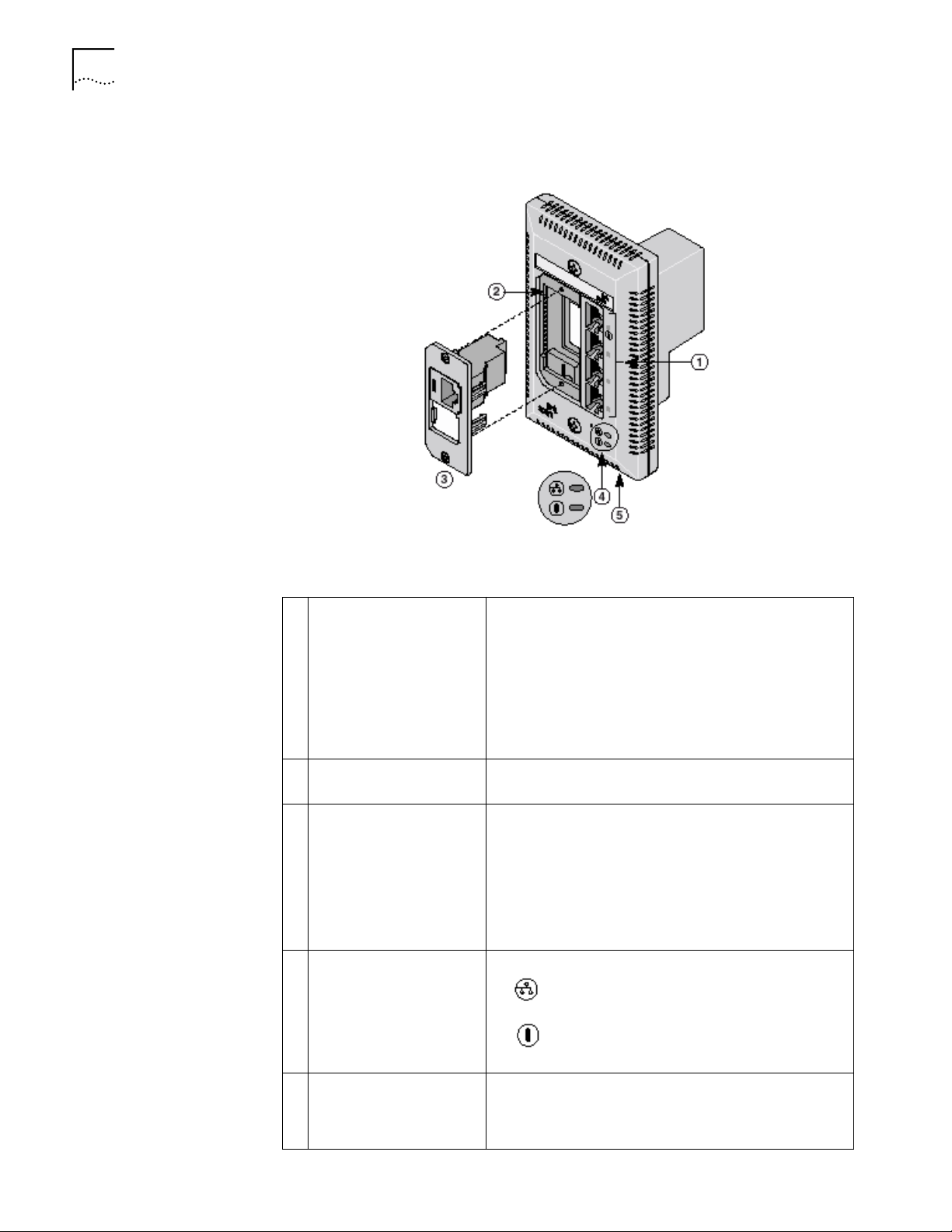
The following diagram shows the front view of the Network Jack:
Switched ports with LEDs Allow up to four devices to be connected to the network.
A green LED indicates connection status when a device is
using a particular port.
Port number 1 is also a power-forwarding port; it can be
used with any standard networking device as well as to
power a VoIP telephone on a network that uses IEEE
802.3af-compatible Power Over Ethernet. An additional
LED indicates when the port is forwarding power to a
device connected to that port.
Slot for adapter plate
Can be fitted with an adapter plate, which can be installed
with up to two pass-through ports.
Adapter plate with
installed pass-through port
connector
Can be used for voice or other networking applications.
The port bypasses the functionality of the switch, allowing
you to set up a connection to a separate network segment
or to connect to an analog or digital PBX telephone.
The adapter plates are available from 3Com. However, you
must purchase the connectors from the manufacturer. See
“Installing the Adapter Plate and Pass-Through Ports” on
page 8 for more information.
LEDs
Indicates network connection status.
Indicates power status.
Power socket Can be used to power the Network Jack with a local
power supply (available for purchase from 3Com);
required if your network does not support Power Over
Ethernet.
Page 7
•
1
2
3
4
Before You Begin 3
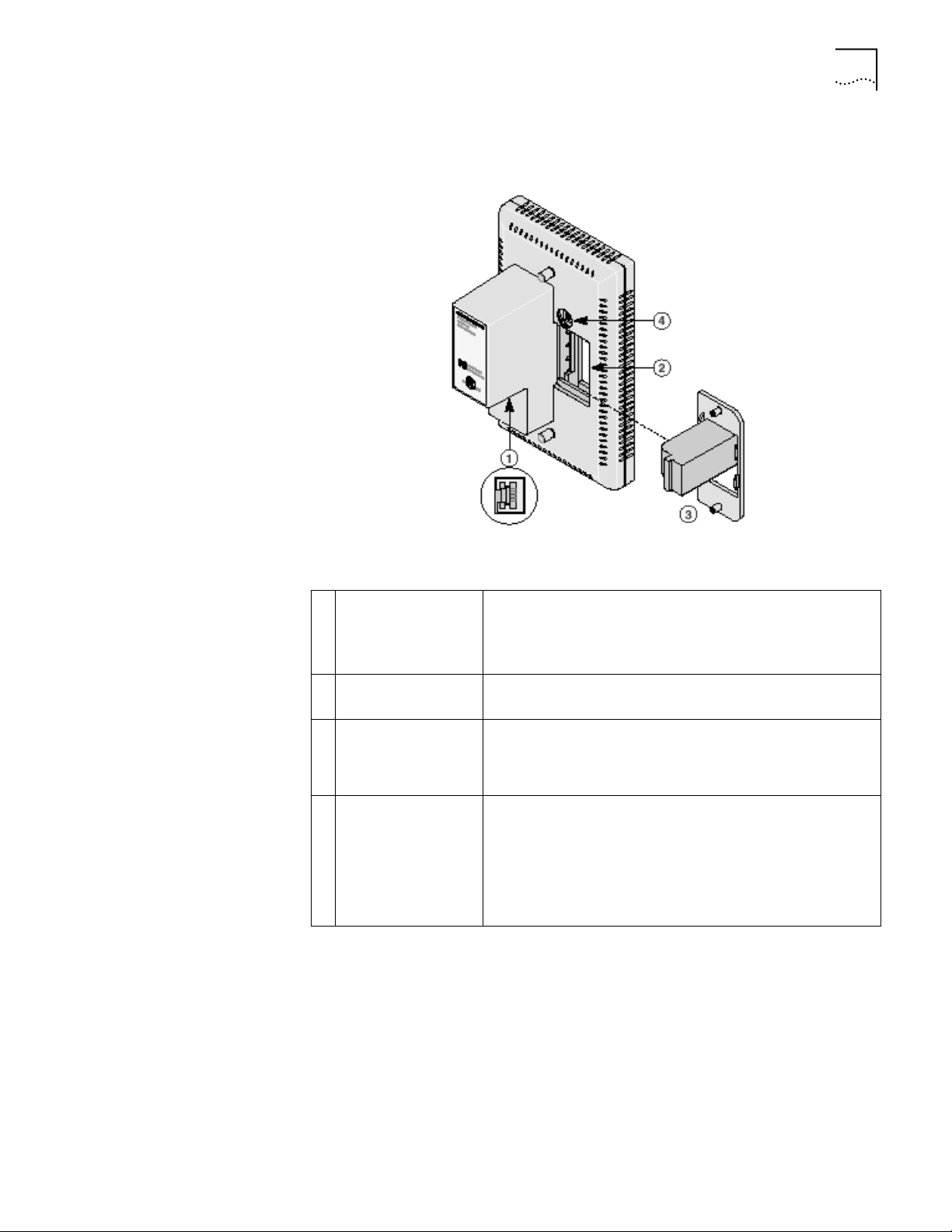
The following diagram shows the back view of the Network Jack:
Before You Begin
Ethernet uplink port
(RJ-45 female)
Slot for adapter plate Can be fitted with an adapter plate, which can be installed with
Adapter plate with
installed
pass-through port
connector
Dip switches
Connects the Network Jack to the network.
Make sure the port on the network switch to which the
Network Jack is connected is configured as a standard MDI-X
port.
up to two pass-through ports.
Connects the installed pass-through port to the network.
Select the type of Power Over Ethernet (Capacitive Power
Discovery Process 24V or 48V or IEEE 802.3af) the Network Jack
uses.
Changing the dip switch settings is required only if your
network supports Power Over Ethernet, or if you are using a
multi-port Ethernet power supply. See “Setting the Power Over
Ethernet Dip Switches” on page 7 for instructions.
Before you begin installation, register your product at:
www.3com.com/productreg.
The Network Jack is available in single- and 20-packs. Before you begin the
installation, make sure you have the following items, which are included with the
Network Jack:
1.5 inch, 6x32 screws (2 per Network Jack) for mounting the Network Jack to
the wall or office cubicle.
Page 8

4
•
•
•
•
C
HAPTER
1: I
NSTALLING
Obtaining Optional Components
NJ200 N
THE
ETWORK
J
ACK
Male to male RJ-45 coupler cable (1 per Network Jack) for connecting the
Ethernet cable from the network to the Network Jack (required only if your
network cable is terminated with a female RJ-45 connector).
Additionally, the following items are shipped with the single pack:
Compact disc with User Guide and Configuration Manager software.
Adapter plates for installing connectors to use as pass-through ports. The
adapter plates accommodate connectors from suppliers including:
n
Panduit (RJ-45 and RJ-11)
n
Avaya (RJ-45 and RJ-11)
NOTE: The connectors for the adapter plates must be purchased from the
manufacturer. For a list of supported connectors, go to www.3com.com/.
Adapter plate screws (2) for mounting the adapter plate to the Network Jack.
The Network Jack works with the following optional components, all of which are
available from 3Com. Order online at www.3com.com or by calling
1-877-949-3266.
Component
Adapter plates
Purpose 3C Number(s)
For installing pass-through port connectors of
your choice that allow a direct connection to
another network segment or for connecting an
analog or digital PBX telephone.
Extension ring For ensuring that the Network Jack is properly
mounted to a cubicle; required if the cubicle
opening:
n
Has a depth of fewer than 1.5 inches.
Does not support the NEMA-WD6 standard.
n
n
Does not have pre-drilled screw holes for
standard mounting.
Single-port Ethernet
power supply
Multi-port Ethernet
power supply
For providing Power Over Ethernet to locally
power a single Network Jack.
For providing Power Over Ethernet to power up
to 24 Network Jacks.
Local power supply For locally powering a single Network Jack;
required if your network does not support Power
Over Ethernet.
VoIP telephone
power cable
For powering a VoIP telephone on a network
that uses Capacitive Power Discovery
Process-compatible Power Over Ethernet.
3CNJAP-PA-20
3CNJAP-AV-20
3CNJEXTRING
3CNJPSE
3CNJPSE24
3C10220
3C10222
3CNJPSL
Check the
3Com web site
Page 9
1
2
3
4
5
6
7
8
9
Installing the Network Jack 5
•
•
•
•
Installing the Network Jack
Installing the Network Jack consists of the following steps:
Set up the power supply (page 5).
If necessary, set the Power Over Ethernet dip switches (page 7; optional, required
only if your network supports Power Over Ethernet or if you are using a single-port
or multi-port power supply).
Install the adapter plate and pass-through ports (page 8).
Plan the installation (page 9).
Set up the network cabling at your site (page 10).
Connect the Network Jack to the network (page 10).
Mount the Network Jack to the wall or office cubicle (page 11).
Connect the local power supply (page 11; optional) not required if your network
supports Power Over Ethernet or if you are using a single-port or multi-port power
supply).
Connect network devices to the Network Jack (page 13).
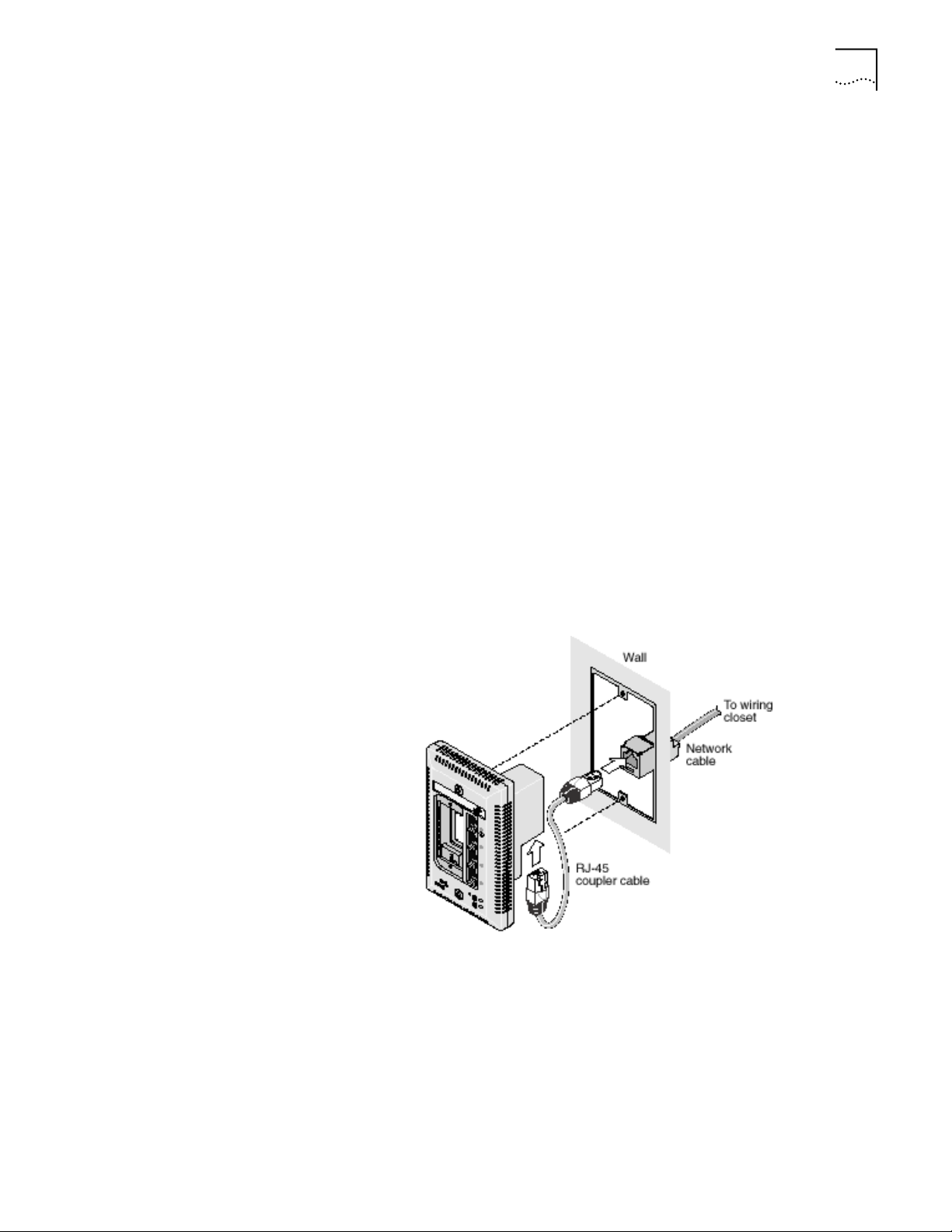
The following diagram displays an overview of the recommended installation,
where the Network Jack is being connected to an Ethernet network cable that is
terminated with a female RJ-45 connector. Detailed installation instructions are
included in the sections that follow.
Setting up the Power
Supply
Power to the Network Jack can be supplied one of the following ways:
Over the network via an integrated switch that supports Power Over Ethernet.
Over the network via a multi-port Ethernet power supply.
Over the network via a single-port Ethernet power supply.
Locally via a 3Com local power supply.
Page 10
6
C
HAPTER
1: I
NSTALLING
NJ200 N
THE
ETWORK
J
ACK
Before you begin the installation, determine which type of power supply the
Network Jack will use.
NOTE: For a list of power supplies that support the Network Jack, go to
www.3com.com/.
CAUTION: Use only a power supply that is provided or approved by 3Com for
use with this Network Jack. Failure to do so may result in damage to the
Network Jack, or may result in a hazardous situation or personal injury.
Using an Integrated Switch with Power Over Ethernet
To use Power Over Ethernet, you must have a switch on the network that has
Power Over Ethernet integrated into it. You must then determine if it is
compatible with Capacitive Power Discovery Process (24V or 48V) or IEEE 802.3af.
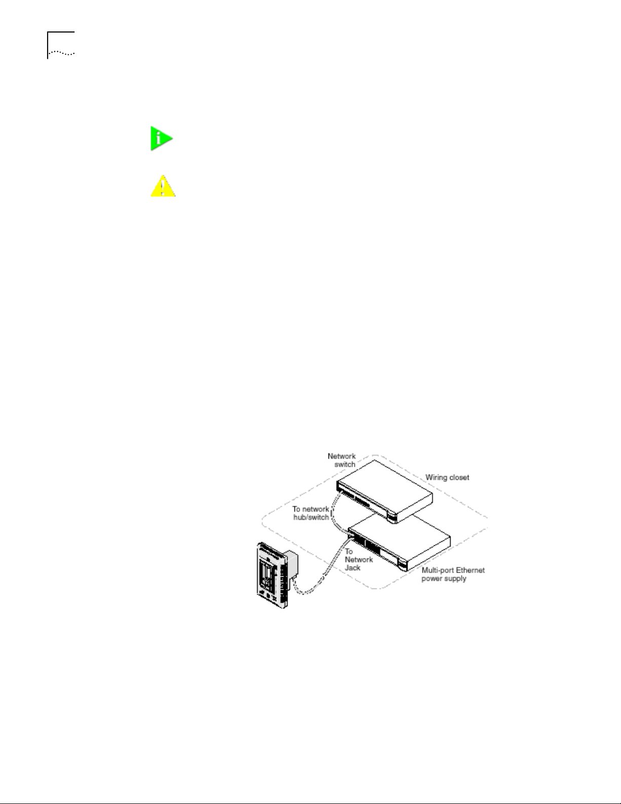
Using a Multi-port Ethernet Power Supply
To use a multi-port Ethernet power supply, you must connect the power supply to
your network, as shown in the illustration.
The multi-port Ethernet power supply from 3Com connects to an existing Ethernet
or Fast Ethernet infrastructure with standard Category 5 or Category 5e UTP
cabling, and powers up to 24 Network Jacks. See “Obtaining Optional
Components” on page 4 for ordering information. For complete installation
instructions, see the multi-port Ethernet power supply documentation.
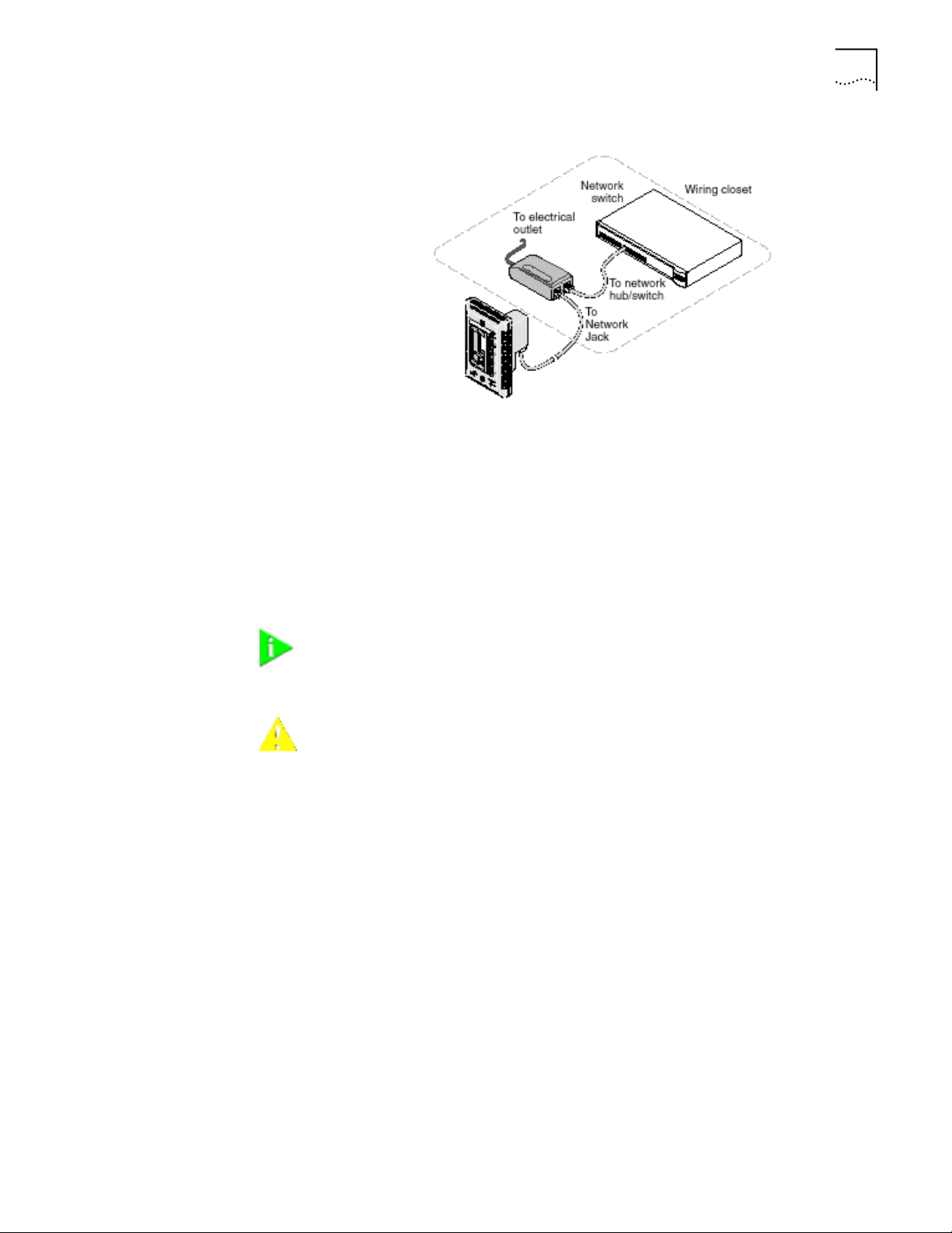
Using a Single-port Ethernet Power Supply
To use a single-port power supply, connect the power supply to the network hub
or switch and to the Network Jack, as shown in the following illustration. See
“Obtaining Optional Components” on page 4 for ordering information. For
complete installation instructions, see the single-port Ethernet power supply
documentation.
Page 11
Installing the Network Jack
7
Using the 3Com Local Power Supply
To use the local power supply, make sure you have an electrical outlet near the
site where the Network Jack will be installed. First plug the power cord into the
Network Jack, then plug it into the electrical socket. See page 12 for more details.
Setting the Power Over
Ethernet Dip Switches
If your network switch or power supply supports Power Over Ethernet, you must
set the dip switches on the Network Jack to the appropriate setting: Capacitive
Power Discovery/24V, Capacitive Power Discovery/48V, or IEEE 802.3af.
NOTE: If you are not using Power Over Ethernet to power the Network Jack,
skip this section. Go to “Installing the Adapter Plate and Pass-Through Ports” on
page 8 to continue.
CAUTION: Before setting the dip switches, make sure that power to the
Network Jack is off.
Do not change dip switches 1 and 2 from their factory default settings (OFF).
Changing these settings may result in performance degradation.
Set the appropriate dip switches (labeled 3 and 4) for the type of Power Over
Ethernet supported. The default setting is IEEE 802.3af-compatible Power Over
Ethernet.
Page 12
8
C
HAPTER
1: I
NSTALLING THE
NJ200 N
ETWORK JACK
Installing the Adapter
Plate and Pass-Through
Ports
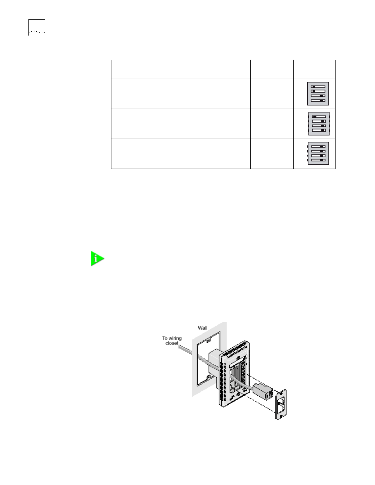
Power Over Ethernet Supported
Capacitive Power Discovery/24V Ethernet Power Source
Capacitive Power Discovery/48V Ethernet Power Source 4 (ON)
IEEE 802.3af-compatible Power Over Ethernet 4 (OFF)
Dip Switch
Numbers
4 (ON)
3 (ON)
3 (OFF)
3 (OFF)
Setting
ON ddddddd 1
ON ddddddd 1
ON ddddddd 1
Install the blank adapter plate, or if you want to use pass-through ports for
connecting an analog or PBX digital telephone or for setting up a connection to a
separate network segment, purchase supported connectors and install them on
the appropriate Network Jack adapter plate (included with the single pack;
available for purchase separately with the 20-pack).
For a list of connectors that are supported with the Network Jack adapter plates,
go to www.3com.com.
4
3
2
4
3
2
4
3
2
NOTE: If you are not planning on installing the adapter plate and pass-through
ports, skip this section. Go to “Planning the Installation” on page 9 to begin the
installation.
1
Pull the network cable(s) from the wiring closet to the location of the Network
Jack.
2
Thread the network cable(s) through the empty slot on the Network Jack.
Page 13
Installing the Network Jack 9
3 Terminate the end of the network cable(s) with the connector(s) you purchased
separately.
Refer to the connector manufacturer’s instructions for terminating the cable. Be
sure to test end-to-end system functionality and verify that it is working.
4 Snap the connector(s) into the appropriate adapter plate.
Each adapter plate is labeled with the name of a connector’s manufacturer. Be
sure to use the adapter plate that matches the manufacturer of your connector(s).
5 Mount the plate to the Network Jack using the two adapter plate screws
provided.
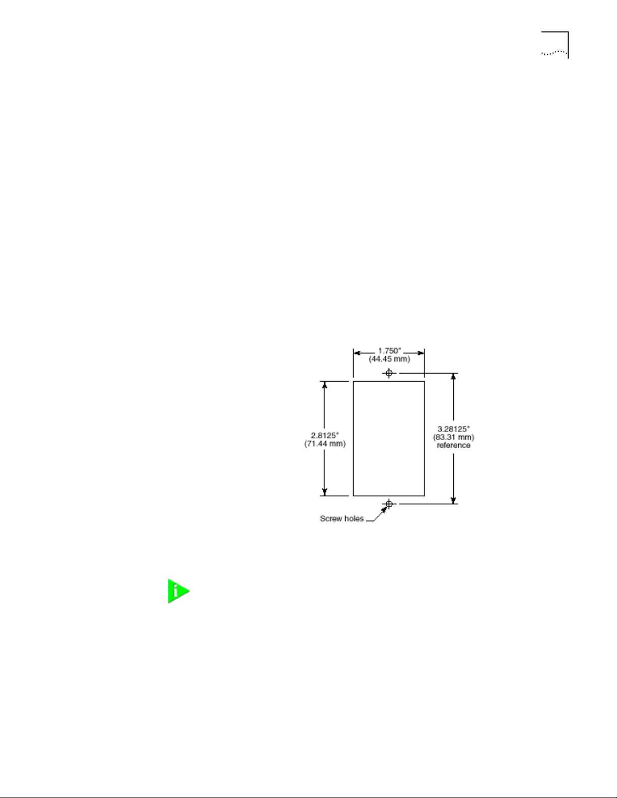
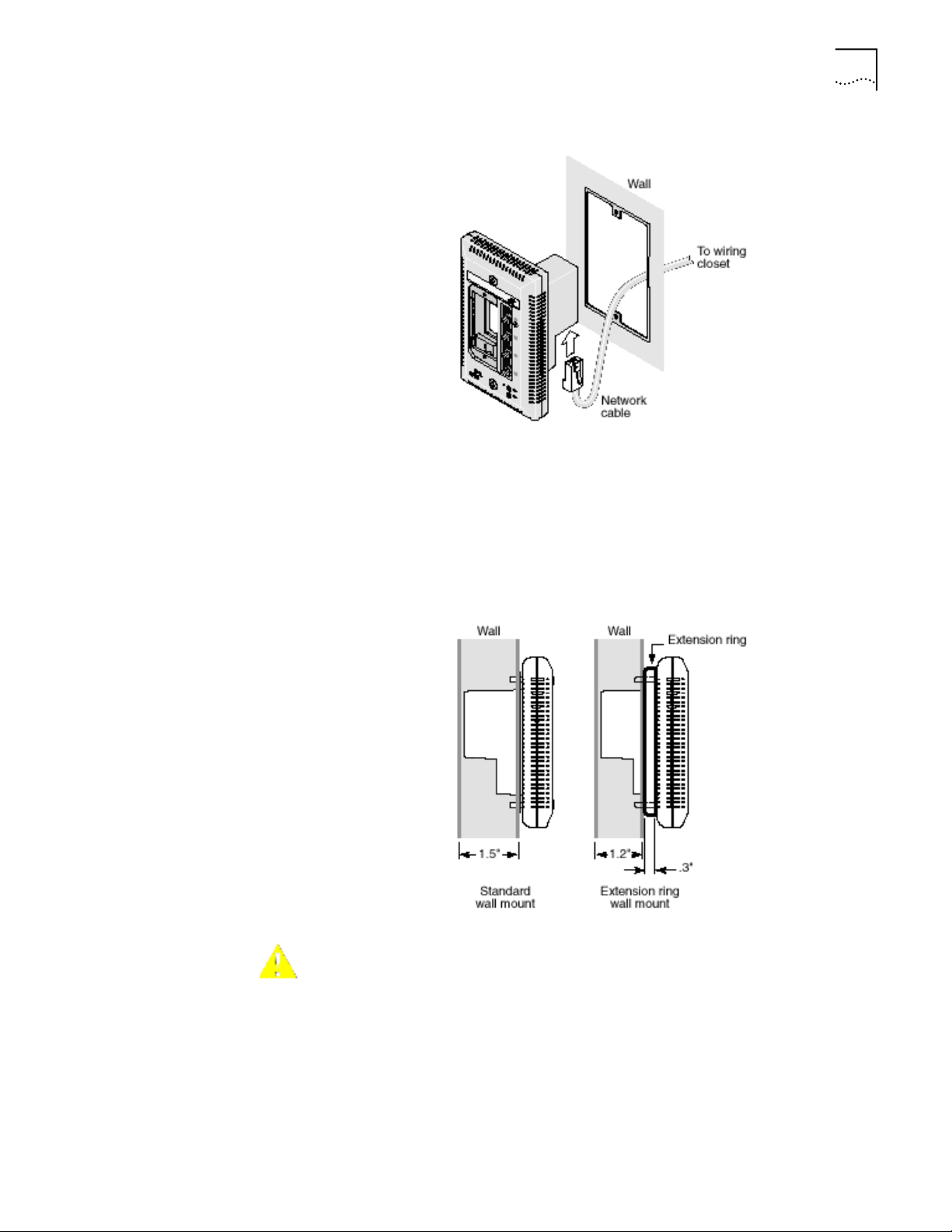
Planning the Installation When installed, the back of the Network Jack extends into a wall or cubicle
opening 1.5 inches. Because the depth of some wall and cubicle openings differ,
observe the following requirements and recommendations before installing the
Network Jack:
• Make sure the wall or cubicle opening where the Network Jack is being
installed complies with the NEMA-WD6 standard, as described below.
• Make sure the distance between the back of the Network Jack and the inside
of the wall or cubicle opening is at least 1.5 inches (3 inches is recommended).
NOTE: Some cubicle openings have a depth of 1.2 inches. In this case, install
the Network Jack using the extension ring (available for purchase separately;
see “Obtaining Optional Components” on page 4) to obtain the minimum
1.5-inch depth.
If installing into a wall junction box, make sure there is enough space between
the back of the Network Jack and the inside of the junction box to maintain an
acceptable bend radius on the cable. If you encounter interference or need
additional clearance between the Network Jack and where it sits inside the
junction box, use the extension ring.
• To ensure proper horizontal cabling functionality, adhere to the following
network cabling standards during installation:
Page 14
10 CHAPTER 1: INSTALLING THE NJ200 NETWORK JACK
n ANSI/TIA/EIA-568
Commercial Building Telecommunications Cabling Standard
n ANSI/TIA/EIA-569
Commercial Building Standard for Telecommunications Pathways and
Spaces
Setting up the Network
Cabling at Your Site
Connecting the Network
Jack to the Network
The network cabling at your site (from the wiring closet to the wall or cubicle
opening) may already be installed. If it is not, install the cabling following these
general guidelines.
CAUTION: It is recommended that a professional cable installer performs these
procedures. Be sure to adhere to local safety and regulatory codes during the
cable installation.
1 Connect one end of an Ethernet cable to your network. Usually, this connection is
done in a network wiring closet, via the patch panel.
2 Terminate the other end of the cable at the location where the Network Jack is
being installed (using either a female or male RJ-45 connector).
Refer to the connector manufacturer’s instructions for terminating the cable. Be
sure to test the connector and verify it is working.
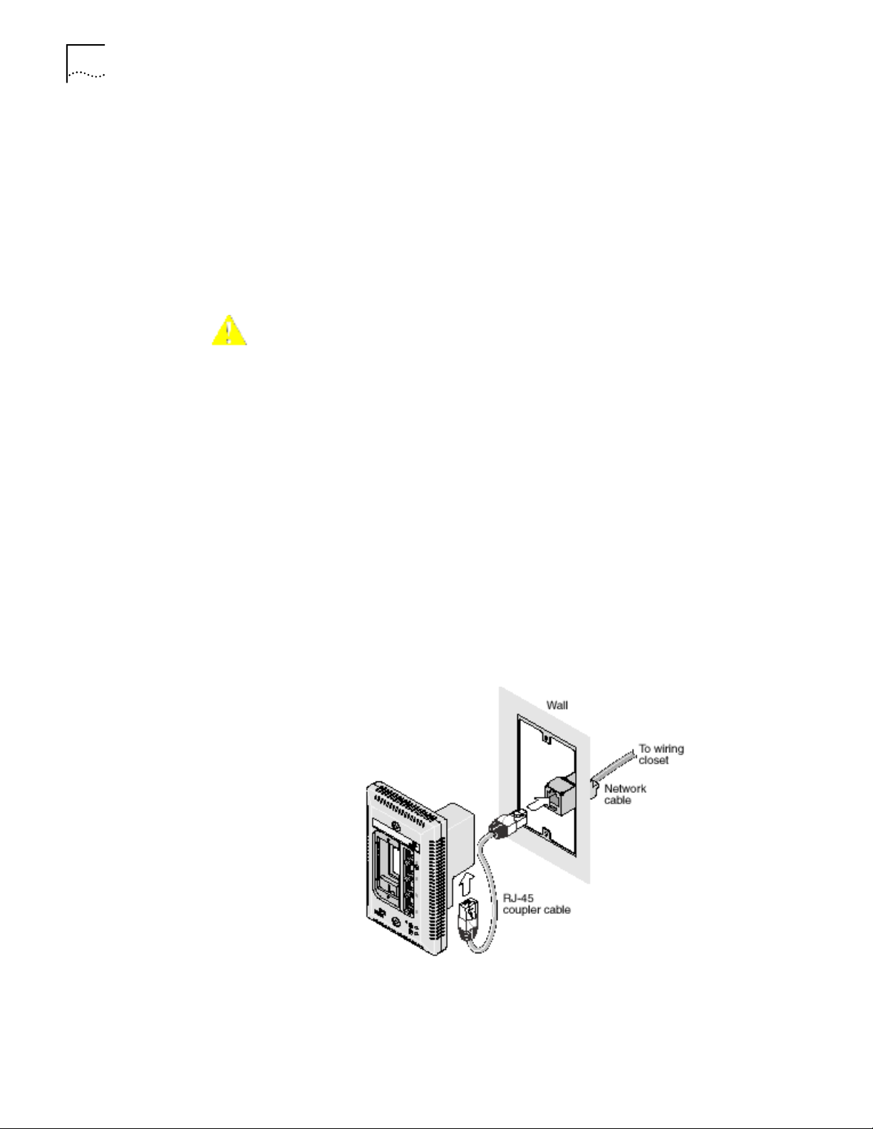
The method for connecting the Network Jack to the network is determined by
how your network cable is terminated (as described in the previous section,
“Setting up the Network Cabling at Your Site”).
• If the end of the cable is terminated with a female RJ-45 connector, use the
RJ-45 coupler cable included in the package to connect the Network Jack to
the network cable (recommended installation.)
• If the end of the cable is terminated with a male connector, connect the
network cable directly into the Ethernet uplink port.
Page 15
Installing the Network Jack 11
Mounting the Network
Jack
After connecting the Network Jack to the network, use the two provided screws
to mount the Network Jack in any standard NEMA-WD6 cubicle opening or wall
outlet.
If the cubicle or wall opening has a depth of fewer than 1.5 inches, does not
support the NEMA-WD6 standard, or does not have pre-drilled screw holes,
mount the Network Jack using the extension ring, as shown below.
Connecting the Local
Power Supply (Optional)
CAUTION: Make sure the vents along the edges of the Network Jack faceplate
are clear of any obstructions. If necessary, install the extension ring on recessed
openings to allow airflow to vents.
If your network does not support Power Over Ethernet, or if you are not using a
single-port or multi-port Ethernet power supply, you must purchase a local power
Page 16
12 CHAPTER 1: INSTALLING THE NJ200 NETWORK JACK
supply from 3Com (see “Obtaining Optional Components” on page 4). To
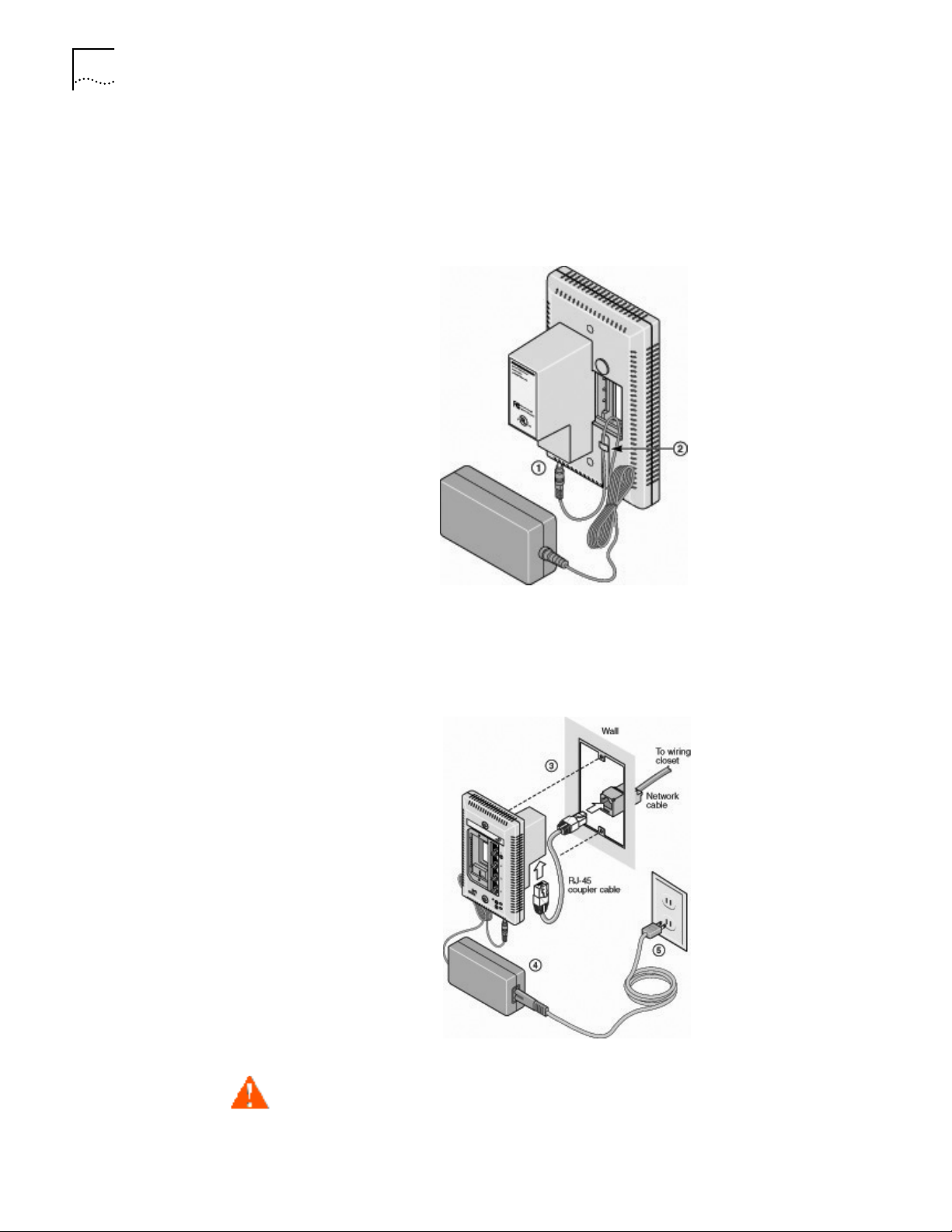
connect the local power supply to the Network Jack, please follow these steps:
1 Route the power cable through the strain relief of the Network Jack (as shown in
the diagram below).
2 Securely mount the Network Jack on a wall.
3 Plug the power cable into the Network Jack.
4 Secure the local power supply and cable to the wall.
5 Plug the local power supply into the power source.
WARNING: Use the local power supply available from 3Com. Failure to do so
may result in damage to the Network Jack, or may result in a hazardous
situation.
Page 17
Checking the LEDs 13
Connecting Devices to
the Network Jack
After the Network Jack is installed and mounted, connect your networking devices
(such as computers, printers, etc.) to any of the four switched ports on the front of
the Network Jack.
If you installed the adapter plate with pass-through ports, connect the appropriate
device(s) to the port(s).
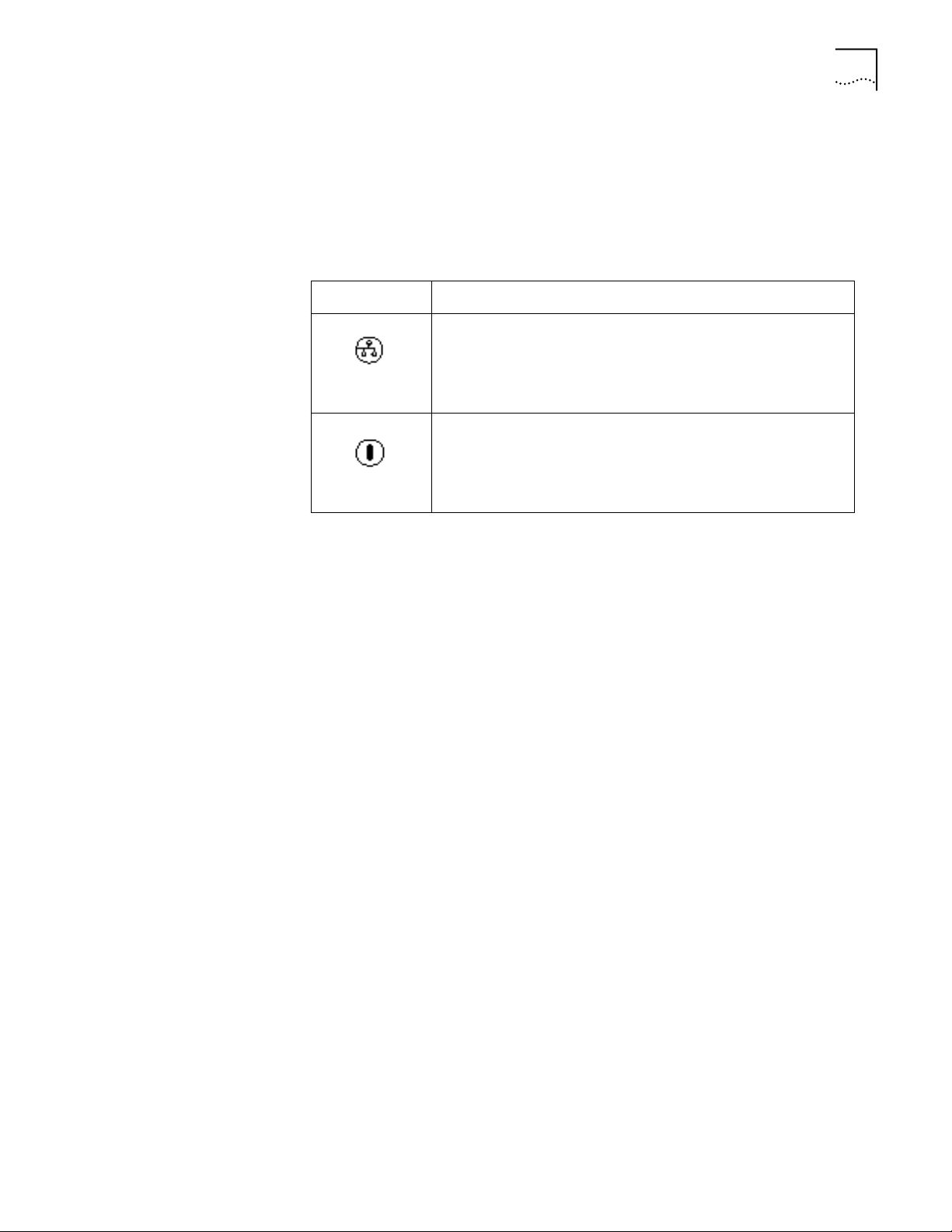
Checking the LEDs You can verify the Network Jack installation by checking the LEDs.
LED Description
n On—The Network Jack is connected to the network and a link
has been established.
n Off—There is no connection to the network.
(LAN)
n On—The Network Jack is receiving power (local or via the
network). When you first connect power to the Network Jack,
there will be a delay of approximately 5 seconds. The power LED
light will blink once or twice before remaining solid on.
(Power)
Additionally, each of the switched ports has a green LED which lights when a
device is connected. Port #1 also has an amber LED which lights when the
Network Jack is forwarding power to a connected device.
n Off—The Network Jack is not receiving power.
Page 18

14 CHAPTER 1: INSTALLING THE NJ200 NETWORK JACK
Page 19

INSTALLING THE
2
System Requirements The machine you install the software on should meet the following requirements:
C
ONFIGURATION MANAGERS
Once you have installed the NJ200 hardware, you need to configure it for use on
your particular network. To configure the NJ200, install the Local and Central
Configuration managers.
NOTE: You will use the Local Configuration Manager for initial configuration of
the NJ200 on your network. It’s usually easiest if you load this software on a
laptop and use it to configure Network Jacks as you install them.
The NJ200 Central Configuration Manager is used for advanced configuration
and management of one or more NJ200s on your network. This software
should be installed on the machine you plan to use to manage your NJ200s
from a remote location—perhaps the same console you use for SNMP
management.
• Pentium processor
Installing the Local and Central Configuration Managers
• Minimum of 15MB disk space
• Windows 2000 or Windows NT 4.0 with Service Pack 6 installed (Windows 95
and Windows 98 are not recommended operating systems for use with
management platforms. In most cases, the Configuration Manager software
will work with Windows 95, 98, or XP. However, please check 3Com’s web site
for additional information regarding XP support)
Run the following steps to install the Configuration Manager software:
1 Insert the Configuration Manager software CD into your Windows 2000 or
Windows NT computer.
2 If your computer is configured to Auto-Play CDs, the installation will start
automatically. If not, double-click the setup.exe icon on the CD, and you will see
this window:
Page 20

16 CHAPTER 2: INSTALLING THE CONFIGURATION MANAGERS
3 Click Next to continue.
4 Carefully read the license agreement. If you agree, click “Yes, I accept” and Next
to continue.
5 Enter your user and organization names and click Next.
Page 21

Installing the Local and Central Configuration Managers 17
6 The program files will be installed in the directory C:\Program Files\3Com\Network
Jack. If you want to change the location of the installation, click Change.
Otherwise click Next to accept the default location and continue.
7 Select a typical or custom setup and click Next. The Typical installation will install
both the Local Configuration Manager and the Central Configuration Manager on
your system. The Custom installation option lets you install just one of the
programs if you wish.
Page 22

18 CHAPTER 2: INSTALLING THE CONFIGURATION MANAGERS
8 Review the settings you selected and click the Install button.
9 When the installation has completed, click the Finish button to close the
installation utility.
Page 23

Installing the Local and Central Configuration Managers 19
The installation utility will create two shortcut icons on the Desktop--one for the
Local Configuration Manager and one for the Central Configuration Manager.
You can also launch the programs from a program group you can access from the
Start menu. The program group folder is labeled 3Com Network Jack and can be
found under the Programs menu.
Page 24

20 CHAPTER 2: INSTALLING THE CONFIGURATION MANAGERS
Page 25

USING THE
3
Initializing the NJ200 Network Jack
LOCAL CONFIGURATION MANAGER
Once you have installed the NJ200 hardware on your network and the Local
Configuration Manager software on your computer, you need to perform an
initial configuration of the Network Jack.
1 The first step is to connect your computer to the NJ200 that you are installing.
Attach an Ethernet cable from a computer running the Local Configuration
Manager software to any one of the four personal area network (PAN) ports on
the front of the NJ200.
2 Click on the desktop shortcut icon labeled NJ200 Local Config Mgr to start the
program. When it launches, you will see a window like this:
3 The MAC address and default IP address of the currently connected NJ200 will
appear in the first field. If you connect to another NJ200, you must click the Query
button to refresh the window.
If you are not connected to any Network Jack, the field will display the message
Not Connected. If the Not Connected message appears, check your connection to
the Network Jack and click the Query button.
4 Make sure the General tab is selected.
5 Enter Location Information for the particular NJ200 you are configuring. This field
can help you and other network managers identify this Network Jack in the
future. You may enter any information you like (up to 256 characters), but we
recommend that you enter a logical, easy to follow description, such as “Building
A, 3rd floor, room 315, West wall.”
Page 26

22 CHAPTER 3: USING THE LOCAL CONFIGURATION MANAGER
6 Enter a Group Name for this Network Jack. This can be any name you wish. With
the Central Configuration Manager, you can perform management tasks on all
Network Jacks with the same group designation.
7 Select the method the NJ200 should use to obtain an IP address. The NJ200 can
either get an IP address from an existing DHCP server on your network or you can
directly specify the address. If you elect to specify your own address, you should
enter the IP Address, Subnet Mask, and Default Gateway information in the
appropriate fields.
NOTE: By default, the NJ200 is configured to automatically obtain an IP address
from a DHCP server. If no DHCP server exists, or if the NJ200 cannot obtain an
IP address, it will default to the IP address 192.168.1.252.
8 If you wish, check the box next to Lock IP Address. Selecting this option will
ensure that the Network Jack will always use a particular address.
WARNING: If you lock an IP address and reserve it for this Network Jack, make
sure you configure your DHCP server so it won’t distribute that address to other
devices.
Setting Advanced Options
9 Click the Configure button and the Local Configuration Manager will ask you to
enter the password for the device. If you haven’t changed the password, you
should enter the default password, which is “password” (without the quotes).
Your changes are sent to the NJ200 and will become effective immediately.
Those are the only steps required to initialize your NJ200 Network Jack.
If you want to change the default password of the NJ200 or manage it from an
SNMP console, you can configure these settings from either the Local
Configuration Manager or the Central Configuration Manager (covered in the
next chapter). In the Local Configuration Manager, both settings are found under
the Advanced tab.
Page 27

Setting Advanced Options 23
1 Select the Advanced tab on the NJ200 Local Configuration Manager window.
2 To change the Network Jack’s configuration password, click on the box next to
Change NJ Password. Then enter the new password in both password fields. (You
must enter the password twice to ensure you entered it correctly.) The password
you select can be any combination of letters and numbers between 8 and 32
characters.
3 To configure the NJ200 for management with an SNMP console, select the SNMP
Configuration box. Enter the GET Community String and SET Community String in
the appropriate fields. Each field lets you enter any combination of letters and
numbers up to 32 characters.
4 Click the Configure button and the Local Configuration Manager will ask you to
enter the password for the device. If you haven’t changed the password, you
should enter the default password, which is “password” (without the quotes).
Your changes are sent to the NJ200 and will become effective immediately.
NOTE: You should change the password to ensure that no one else can
re-configure your system. Make sure you remember the new password you set.
If you forget the new password, you will not be able to perform any
other configuration tasks unless you send the device back to 3Com.
Page 28

24 CHAPTER 3: USING THE LOCAL CONFIGURATION MANAGER
Page 29

USING THE
4
Discovering NJ200 Devices on Your Network
CENTRAL CONFIGURATION MANAGER
You should use the Local Configuration Manager to initialize each of the NJ200
Network Jacks installed on your network. Once you have completed that step, you
can manage all of them with the Central Configuration Manager.
Install this program on any computer on your network you want to use as a
central management console (See chapter 2, “Installing the Configuration
Managers” for help). You can use the same machine that has your SNMP-based
management platform. The Central Configuration Manager will be able to
configure and manage all of the Network Jacks that reside on your network.
In order to manage the NJ200 Network Jacks on your network, the Central
Configuration Manager needs to include them in its database. The easiest way to
add new NJ200 Network Jacks to the database is to use the device discovery tool
included in the Central Configuration Manager. The first time you run the Central
Configuration Manager, it will automatically take you to the Discovery window as
shown under step two below. To discover devices on your network, run the
following steps:
1 Open the Central Configuration Manager by double-clicking on the NJ200 Central
Config Mgr desktop icon. When it launches, you will see a window similar to this
one:
Page 30

26 CHAPTER 4: USING THE CENTRAL CONFIGURATION MANAGER
2 Select Discovery from the Devices menu. The following window will appear:
NOTE: The default subnets are the ones your machine is connected to.
3 You can discover new devices based on a specific subnet or on a specific range of
IP addresses.
a To discover devices by subnet, select that option on the screen. Click the Add
button to add a new subnet to the discovery list. The following box will appear:
Fill in the Subnet and Mask fields and click OK.
or
b To discover devices within a certain IP range, select that option on the screen
and complete the From and To fields.
Page 31

Viewing Device Properties 27
4 If the box next to “Delete all devices in the existing list” is checked, the discovery
process will replace all of the devices in your current database with the new
devices it discovers. If unchecked, the discovery process will add newly discovered
devices to the current database.
5 Click OK to start the discovery process.
The device discovery tool will return the following information from the NJ200
Network Jacks on your network:
• IP address
• MAC address
• Subnet address
• Group Name
• Location information
• Firmware version
You can sort this information in ascending or descending order.
NOTE: Discovered devices are automatically added to the default database.
This default database will open automatically when you launch the Central
Configuration Manager. If you like, you can keep several database files, each
with its own list of devices. For example, you may want a separate database for
each subnet you manage. To save a database file or open another database file,
select the Open Database or Save Database As options from the File menu.
You can view discovered devices many ways. On the left side of the window,
under the toolbar, you can see a drop down box with options for either Subnet,
Firmware Ver, or Group Name. The option you select in this box determines how
the views are displayed in the left pane of the window.
When Subnet is selected (the default option), you will see a list of IP subnets to
choose from. Selecting Network will show all of the discovered devices in the
database. If you select a particular subnet, only the devices in that subnet will be
displayed.
When Firmware Ver is selected, you will see a list of the different firmware
versions loaded on the devices. This view is particularly useful if you want to select
only the devices with an old firmware version so you can perform an upgrade.
When you select Group Name from the drop down list, the Central Configuration
Manager will present a list of the different group names you have specified.
Viewing Device Properties
Once the database is populated with NJ200 Network Jacks on your network, you
can begin to manage those devices. The main window of the Central
Configuration Manager shows a list of devices in the current database with the
information retrieved during the discovery process. You can view and configure
the properties for a single NJ200 using this window. To configure multiple devices
Page 32

28 CHAPTER 4: USING THE CENTRAL CONFIGURATION MANAGER
at one time, see “Changing Device Configuration” on page 31. To get more
detailed information about a device, you should check its properties:
1 Select a Network Jack from the devices list.
2 Select Property from the Devices menu or from the toolbar. You can also open this
window by right-clicking your mouse and selecting Property.
3 With the General tab selected, you can view and edit information about the
device such as the IP address, subnet mask, default gateway, and whether it uses
a static IP address or gets its address from a DHCP server. You can also view and
edit the Network Jack’s Group Name and Location information.
4 Click Apply to save any changes you make to the fields in this window.
5 In the middle of this window you’ll see information about each of the four PAN
ports on the front of the Network Jack. You can check to see if the port is Enabled
or Disabled, if there is a network link, whether or not it’s running at half or full
duplex, what speed it’s set for, its priority, and whether or not it’s part of a virtual
network (VLAN).
6 Under the Product Info box, you can see the current firmware version of the
Network Jack, the Product Name, and the Serial Number.
Page 33

Viewing Device Properties 29
7 Click on the Hardware Settings tab to view status information about the switch.
Several fields in this window can be edited, a few cannot. You can change the
values of the fields with drop-down lists: Priority Schedule Policy, LAN Port Egress
Mode, LAN Port Ingress Mode, Max Frame Size, Counter Mode, and Power
Forwarding.
8 Simply select the value you wish to change from the drop-down list of options.
NOTE: You can click Apply at any time to save the changes you have made. But
be sure to click Apply after you have finished making all your changes.
Page 34

30 CHAPTER 4: USING THE CENTRAL CONFIGURATION MANAGER
9 Click on the Statistics tab.
From this view you can see statistics about the number of good or bad packets
each port has received and transmitted, based on how you have configured the
Counter Mode setting (see step 8 on page 33).
You can reset all counters to zero by clicking Clear.
Page 35

Changing Device Configuration 31
10 Click on the SNMP Settings tab to see the following window:
Changing Device Configuration
11 You can view and edit the SNMP Common Settings and Trap Settings for this
particular NJ200.
12 Click Apply to save any changes you make and a configuration summary dialog
box will appear. Verify the information and click OK.
13 Click Exit to close the Device Property window.
Many of the properties that you can view from the Device Property windows can
be changed from the Device Configuration window. Here’s how to use this
feature:
1 Select one or more Network Jacks from the devices list.
NOTE: It is possible to configure multiple Network Jacks at the same time.
Page 36

32 CHAPTER 4: USING THE CENTRAL CONFIGURATION MANAGER
2 Select Configuration from the Devices menu or the toolbar or right click on a
device and select Configuration from the pop-up menu.
NOTE: To make configuration changes to a Network Jack from the Central
Configuration Manager, the NJ200 must already be discovered and part of the
device database, and you must be able to communicate with the device from
your workstation. If you can’t communicate with the device at this time, you
will receive an error message when you try to configure the unit.
This window has six tabs across the top--General, Priority, VLAN, Security, SNMP
Traps, and Advanced. Check the box next to any setting you want to change from
within these six areas.
3 Select the General tab.
4 To change or set the Group Name, check the box next to that field. You can set a
Group Name to anything you want, up to 256 characters.
5 Change or set the Location Name by checking the box next to that field and
entering up to 256 characters.
6 Configure the DHCP setting to the desired state.
7 Change the Port and Link states of any of the Network Jack’s ports by checking
the box next to the characteristic you want to modify and selecting a value from
the drop list.
Page 37

Changing Device Configuration 33
8 By default, the Central Configuration Manager will display a count of good
transmissions in the Property window. If you would rather track errors and
collisions, select that option in the Counter Mode setting.
9 Click the Priority tab along the top of the Device Configuration window to view
these settings:
10 From this screen you can change the Look Up Scheme and Default Priority Level of
each port on the NJ200 and the Priority Scheduling Policy of the Network Jack
itself. Check the box next to the setting you want to change and select an option
from the drop-down list.
Page 38

34 CHAPTER 4: USING THE CENTRAL CONFIGURATION MANAGER
11 Click the VLAN tab to configure your Network Jack for use in a virtual LAN.
12 From this window you can associate any of the four ports with any other ports on
this Network Jack to form a VLAN group. You can specify the tag schemes for the
VLAN you create.
NOTE: VLAN stands for Virtual Local Area Network. VLANS are used to create a
subgroup of systems within a LAN in order to isolate traffic between network
devices. The NJ200 supports VLAN tagging, but does not route inbound traffic
on a per-port basis.
If you change your VLAN settings, they should be consistent with your
network’s VLAN settings.
Page 39

Changing Device Configuration 35
13 Select the Security tab to set the security options of the NJ200 Network Jack.
14 You can change the device password (the default password is “password”), and
adjust the SNMP Set permissions and Community Strings.
Page 40

36 CHAPTER 4: USING THE CENTRAL CONFIGURATION MANAGER
15 Click the SNMP Traps tab to change the trap settings of the NJ200.
16 From this window you can enable or disable the device’s Cold Start, Link Down,
Link Up, and Authorization Fail traps to be sent to your SNMP console.
Page 41

17 Select the Advanced tab for this window:
Changing Device Configuration 37
18 You can change the Max Frame Size and Power Forward settings by selecting an
option from the drop-down list.
19 From this window, you can see another set of tabs, one for each port on the
Network Jack. Click on the port whose settings you want to change, check the
box next to the setting to be changed, and select a value from the drop-down list.
You can change the Flow Control, the AutoMDI(X) crossover capabilities, and the
Multicast Rate Limit.
20 At the bottom of this window is an option to restore some of the configuration
settings to their default values. If you check this box, the following settings will be
restored:
Global Setting Default Value
Max Frame Size 1518 or 1522 if tagged
Counter Mode Count good frames
Priority Scheduling Mode 8, 4, 2, 1 weighted
VLAN Tag for LAN Port (egress) Egress frame unmodified
VLAN Tag for LAN Port (ingress) Ingress frame unmodified
Power Forward Auto detection
SNMP “Set” Permission Not allowed
Page 42

38 CHAPTER 4: USING THE CENTRAL CONFIGURATION MANAGER
Port Setting Default Value
State Forwarding
Link Auto negotiation
Flow Control Off
MDI[X] Force MDI
Multicast Limit 3%
Priority Lookup Tag & IPV4
Port Priority 1
VLAN ID 1
Port based VLAN All ports on same VLAN
The values that remain unchanged when you click Restore Factory Default Settings
are:
• Group Name
• Location ID
• Password
• IP Address
• DHCP Settings
• SNMP Community Strings
• SNMP Trap Settings
21 When you are finished entering the configuration changes to your NJ200 Network
Jack, click the OK button and a Configuration Progress dialog box will appear. If
you don’t want to apply the changes you made, click Exit to discard those changes
and exit the window.
Page 43

Finding Computers Connected to NJ200 Devices 39
22 If you click Configuration Summary, you will see a summary of all the changes you
have made. Enter your password and click Start. As the Network Jacks are
configured, their status will be updated in the Status column.
NOTE: If a NJ200 Network Jack that was once discovered by the Central
Configuration Manager is no longer connected to your network or if you just
want to remove a device from the current database, you can select Delete
Device from the Devices menu.
Finding Computers Connected to NJ200 Devices
Occasionally you may need to find out which Network Jack a networked device,
such as a PC, is connected to. This is one of the many situations where the
Location Information field of the NJ200 can be very useful.
If you know the IP address or MAC address of the computer or networked device,
you can use the Central Configuration Manager to find the right Network Jack.
1 Select Find Location from the Tools menu. You will see a window like this:
2 Enter the IP address or the MAC address of the PC you wish to find.
3 Click the Find button.
When the search is complete, the Search Results field will display the IP address of
the NJ200 that the PC is connected to. It will also show the Location Name
assigned to the Network Jack and which port the PC is using.
4 Click OK to close the window.
Page 44

40 CHAPTER 4: USING THE CENTRAL CONFIGURATION MANAGER
Upgrading the NJ200 Firmware
You can upgrade the firmware on your NJ200s over the network from the Central
Configuration Manager. To do so, follow these steps:
1 Select one or more Network Jacks you want to upgrade. You can select groups of
Network Jacks using one of the grouping options available to you in the
drop-down list at the top left corner of the main window.
2 Select Upgrade from the devices menu. A window like this will appear:
3 Select Yes to continue the upgrade operation. A window like this will appear:
4 Select a valid firmware image by typing the path to the file or by using the Browse
button.
Page 45

Upgrading the NJ200 Firmware 41
5 Select the time to perform the upgrade. You can either send the update file
immediately or select a specific time and date to send the file. You may, for
example, want to perform an upgrade during off hours such as a weekend.
6 Click Next and a window like this will appear:
7 Review the list of Network Jacks you want to upgrade. If you want to modify this
list, click Cancel and restart the firmware upgrade procedure.
Page 46

42 CHAPTER 4: USING THE CENTRAL CONFIGURATION MANAGER
8 Type your password in the Password field, then click Finish. The Upgrade Progress
dialog box will appear.
Page 47

Upgrading the NJ200 Firmware 43
Viewing Log Files The Central Configuration Manager creates a log file with details of the firmware
upgrade operation. This file is in the Central Configurator\Log subdirectory under
the directory where you installed the Network Jack configuration software. You
can also view a history of firmware upgrades by selecting Log History from the
View menu. A window like this will appear:
To view the details of a particular log, select it and click Detail. If the firmware
upgrade of an NJ200 unit fails for some reason, a message will appear in the
upgrade progress dialog box and the log file. Consult the troubleshooting guide
on page 45 for more information.
Page 48

44 CHAPTER 4: USING THE CENTRAL CONFIGURATION MANAGER
Viewing and Canceling
Scheduled Firmware
Upgrades
You can select a time and date to send an upgraded firmware image to the
Network Jacks in your network. To view and make changes to the firmware
upgrades you have scheduled, follow these steps:
1 Select Scheduled Upgrade from the View menu. A window like this will appear:
2 To view the details of a scheduled upgrade, select it from the list and click Show
Devices. To cancel a scheduled upgrade, select it from the list and click Delete.
Page 49

A Troubleshooting the NJ200
If you encounter problems with the Network Jack:
■ Verify the Network Jack is receiving power by viewing the Power LED (it should be
on). If the Power LED is not on, make sure the:
■ Power Over Ethernet dip switches are set correctly (for either Capacitive Power
Discovery Process 24V or 48V or IEEE 802.3af), if your network supports Power
Over Ethernet. See “Setting the Power Over Ethernet Dip Switches” on page 7
for instructions.
If using Power Over Ethernet, make sure the other end of the network cable is
plugged into a switch on the network that has Power Over Ethernet integrated
into it, or one that feeds into an external midspan power supply that supports
Power Over Ethernet.
■ Local power supply is plugged into the Network Jack and into a working
electrical outlet, if your network does not support Power Over Ethernet.
■ Verify the Network Jack is connected to the network properly by viewing the Link LED
(it should be on). If the Link LED is not on, make sure the network cable:
■ Is terminated properly. Refer to the connector manufacturer’s instructions for
terminating the cable. Be sure to test the connector and verify it is working.
■ Has a valid connection to the network.
■ Adheres to proper length and cabling specifications for your network.
■ The Network Jack is configured for manual MDI. Be sure to use a straight-through
cable. If you want to use a cross-connect cable, you must change settings in the
Configuration Manager software.
Troubleshooting Matrix
Event/Message Description Solution
Power LED is not on Network Jack is not receiving
Link LED is not on Network Jack has no
power
connection to the network
Ensure power supply is properly
connected.
For power over Ethernet, make sure dip
switch settings are correctly set and that
cable is connected to both the LAN port
on the back of the Network Jack and to
the workgroup switch.
Make sure network cable is properly
terminated. Make sure the Network Jack
is connected to the network. Make sure
the cable is plugged into the workgroup
switch.
45
Page 50

Troubleshooting the NJ200
Event/Message Description Solution
Green LEDs on Ports 1-4
are not on
Amber LED on Port 1 is
not lit
Authentication Failure Wrong password has been
Timeout Device did not respond
Attributes Error Unexpected configuration
General Error Something other than
Network device has no
connection to Network Jack
ower is not being
P
forwarded to network
device
entered
within a specified period of
time
parameters
authentication failure,
timeout or attributes error
has occurred
Make sure the cable is properly
connected to the network device. Make
sure the cable is firmly connected to one
of the four Network Jack ports labeled 1-
4. Make sure the cable is a good straightthrough cable.
Make sure the cable is properly
connected to the network device. Make
sure the cable is firmly connected to one
of the four Network Jack ports labeled 1-
4. Make sure the cable is a good straightthrough cable. Make sure network
device is 802.3af compatible. Make sure
the power requirement for network
device does not exceed 7 watts.
Confirm correct password and re-type.
Refresh the screen after a few seconds. If
the problem persists, try to rediscover the
device.
Confirm that you have specified valid
parameter values and retry the
configuration operation.
NOTE: This error should not appear to the
user under normal conditions.
Retry the operation you were performing.
NOTE: This error should not appear to the
user under normal conditions.
46
Page 51

B Technical Support
3Com provides easy access to technical support information through a variety of services.
This appendix describes these services.
Information contained in this appendix is correct at time of publication. For the most
recent information, 3Com recommends that you access the 3Com Corporation World
Wide Web site.
Online Technical Services
Register for support at support.3com.com/registration/frontpg.pl
3Com offers worldwide product support 24 hours a day, 7 days a week, through the
following online systems:
■ World Wide Web site
■ 3Com Knowledgebase Web Services
■ 3Com FTP site
■ 3Com Connection Assistant
World Wide Web Site
To access the latest networking information on the 3Com Corporation World Wide Web
site, enter this URL into your Internet browser:
http://www.3com.com/
This service provides access to online support information, such as technical documentation
and a software library, as well as support options that range from technical education to
maintenance and professional services.
3Com Knowledgebase Web Services
The 3Com Knowledgebase is a database of technical information to help you install,
upgrade, configure, or support 3Com products. The Knowledgebase is updated daily with
technical information discovered by 3Com technical support engineers. This
complimentary service, which is available 24 hours a day, 7 days a week to 3Com
customers and partners, is located on the 3Com Corporation World Wide Web site at:
http://knowledgebase.3com.com
3Com FTP Site
Download drivers, patches, software, and MIBs across the Internet from the 3Com public
FTP site. This service is available 24 hours a day, 7 days a week.
To connect to the 3Com FTP site, enter the following information into your FTP client:
■ Hostname: ftp.3com.com
■ Username: anonymous
■ Password: <your Internet e-mail address>
47
Page 52

Technical Support
NOTE: With Web browser software, such as Netscape Navigator and
Internet Explorer, you do not need a user name and password.
3Com Connection Assistant
The 3Com Connection Assistant is interactive software that gives you an easy
to use diagnostic and repair tool. Using this tool makes troubleshooting easier
and helps you quickly resolve problems. Go to:
Start/Programs/3Com NIC Utilities/3Com Connection Assistant
to find the utility.
By using the Connection Assistant you can:
■ Automatically check your computer and repair problems
■ Search for solutions for specific hardware or software problems
■ Find answers to your questions about business processes. tasks, and
applications
■ Connect, via the Internet, to technical support when you need assistance
with your computer hardware and software
■ Get assistance even if you are not connected to the Internet
For more information about 3Com Connection Assistant, contact your help desk
directly or visit us at: www.3com.com/connectionassistant
Support from Your Network Supplier
If you require additional assistance, consult your network supplier. Many suppliers are
authorized 3Com service partners who are qualified to provide a variety of services,
including network planning, installation, hardware maintenance, application training, and
support services.
When you consult your network supplier, have the following information ready:
■ Product model name, part number, and serial number
■ A list of system hardware and software, including revision levels
■ Diagnostic error messages
■ Details about recent configuration changes, if applicable
If you are unable to consult your network supplier, see the following section on how to
contact 3Com.
48
Page 53

Support from 3Com
Support from 3Com
If you are unable to obtain assistance from the 3Com online technical resources or from
your network supplier, 3Com offers technical telephone support services. To find out more
about your support options, go to the Web site associated with your region of the world
shown below.
Region URL for Regional Web Site
Asia and the Pacific Rim ap.3com.com/contacts/support-contacts.html
Africa, Europe, and the
Middle East
Latin America lat.3com.com/lat/support/index.html
North America csoweb4.3com.com/contactus/
When you contact 3Com for assistance, have the following information ready:
■ Product model name, part number, and serial number
■ A list of system hardware and software, including revision levels
■ Diagnostic error messages
■ Details about recent configuration changes, if applicable
emea.3com.com/support/supportnumbers.html
Returning Products for Repair
Before you send a product directly to 3Com for repair, you must first obtain an
authorization number. Products sent to 3Com without authorization numbers will be
returned to the sender unopened, at the sender’s expense. To obtain an authorization
number, go to the Web site listed above for your region.
49
Page 54

Technical Support
50
Page 55

C Product Specifications
Hardware
Power consumption <5 watts without power forwarding
Maximum 13 watts with power forwarding (depending on the
device drawing power)
Network Interface
10 Mbps Ethernet
10BASE-T
100 Mbps Ethernet
100BASE-TX
Performance
Auto-negotiation Communication speed (10 Mbps or 100 Mbps) and duplex mode
Ethernet IEEE 802.3 industry standard for a 10 Mbps baseband
CSMA/CD local area network
Ethernet IEEE 802.3u industry standard for a 100 Mbps baseband
CSMA/CD local area network
(full or half) can be determined through auto-negotiation with
the attached devices. The Network Jack attempts to negotiate the
fastest connection possible (100 Mbps full-duplex).
The communication speed and duplex mode can also be
controlled using the configuration management software.
51
Page 56

Product Specifications
Environment
Operating temperature 32° to 104° F (0° to 40° C)
Storage temperature -22° to 194° F (-30°- to 90° C)
Operating humidity 10-90% noncondensing
Storage humidity 10-90% noncondensing
Operating Altitude 8,000 ft. max
Storage Altitude 20,000 ft. max
Standards
Conformance
IEEE 802.3 10BASE-T, 100BASE-TX and auto-negotiation
Power Over Ethernet (Capacitive Power Discovery Process and IEEE 802.3af)
Power forwarding (IEEE 802.3; 6 watts, 48 volts)
Features
Power Over Ethernet Compatible with IEEE 802.3af and Capacitive Power Discovery
Local power supply Required for networks that do not support Power Over Ethernet
Voice Over IP (VoIP) Compatible with VoIP standard.
Power forwarding Power forwarding Port number 1 can be used with any standard
Process
networking device as well as to power a device such as a VoIP
telephone on a network that uses IEEE 802.3af-compatible Power
Over Ethernet.
52
Page 57

REGULATORY INFORMATION
FCC COMPLIANCE This device complies with part 15 of the FCC Rules. Operation is subject to the following two conditions: (1) This device may
not cause harmful interference, and (2) this device must accept any interference received, including interference that may
cause undesired operation.
FCC CLASS A VERIFICATION
S
TATEMENT
INDUSTRY CANADA (IC)
C
OMPLIANCE STATEMENT
AVIS DE CONFORMITÉ À LA
RÉGLEMENTATION
D’INDUSTRIE CANADA
NOTE: This equipment has been tested and found to comply with the limits for a Class A digital device, pursuant to Part 15 of
the FCC Rules. These limits are designed to provide reasonable protection against harmful interference in a commercial
installation. This equipment generates, uses and can radiate radio frequency energy and, if not installed and used in
accordance with the instructions, may cause harmful interference to radio communications. Operation of this equipment in a
residential area is likely to cause harmful interference, in which case, the user will be required to correct the interference at the
user’s own expense.
Changes or modifications not expressly approved by 3Com could void the user’s authority to operate this equipment.
This Class A digital apparatus complies with Canadian ICES-003.
Cet appareil numérique de la classe A est conform à la norme NMB-003 du Canada.
Manual version 1.0
September 23, 2002
Page 58

 Loading...