

Page 1
NBX® Administrator’s Guide
V3000 Analog
V3000 BRI
V3001R
V5000
NBX 100
Release 6.0
Part Number 900-0212-01 AA
Published August 2006
http://www.3com.com/
Page 2

3Com Corporation
350 Campus Drive
Marlborough, MA
01752-3064
Copyright © 1998 – 2006, 3Com Corporation. All Rights Reserved. No part of this documentation may be
reproduced in any form or by any means or used to make any derivative work (such as translation,
transformation, or adaptation) without written permission from 3Com Corporation.
3Com Corporation reserves the right to revise this documentation and to make changes in content from
time to time without obligation on the part of 3Com Corporation to provide notification of such revision
or change.
3Com Corporation provides this documentation without warranty, term, or condition of any kind, either
implied or expressed, including, but not limited to, the implied warranties, terms, or conditions of
merchantability, satisfactory quality, and fitness for a particular purpose. 3Com may make improvements
or changes in the product(s) and/or the program(s) described in this documentation at any time.
If there is any software on removable media described in this documentation, it is furnished under a
license agreement included with the product as a separate document, in the hardcopy documentation, or
on the removable media in a directory file named LICENSE.TXT or !LICENSE.TXT. If you are unable to
locate a copy, please contact 3Com and a copy will be provided to you.
UNITED STATES GOVERNMENT LEGENDS:
If you are a United States government agency, then this documentation and the software described herein
are provided to you subject to the following:
United States Government Legend: All technical data and computer software is commercial in nature
and developed solely at private expense. Software is delivered as Commercial Computer Software as
defined in DFARS 252.227-7014 (June 1995) or as a commercial item as defined in FAR 2.101(a) and as
such is provided with only such rights as are provided in 3Com’s standard commercial license for the
Software. Technical data is provided with limited rights only as provided in DFAR 252.227-7015 (Nov
1995) or FAR 52.227-14 (June 1987), whichever is applicable. You agree not to remove or deface any
portion of any legend provided on any licensed program or documentation contained in, or delivered to
you in conjunction with guide.
Unless otherwise indicated, 3Com registered trademarks are registered in the United States and may or
may not be registered in other countries.
3Com, the 3Com logo, and NBX are registered trademarks of 3Com Corporation. NetSet and pcXset are
trademarks of 3Com Corporation.
Other brand and product names may be registered trademarks or trademarks of their respective holders.
Page 3

CONTENTS
ABOUT THIS GUIDE
How to Use This Guide 19
Conventions 20
International Terminology 20
Your Comments 21
1 INTRODUCTION
Network-based Telephony 23
NetSet Administration Utility 24
NetSet User Interface 25
2 SYSTEM SETTINGS
Auto Discovery 27
Initial System Configuration 29
Disabling the Auto Discovery Feature 30
Enable Features System-Wide 30
How Call Timer Works With Other Telephone Features 31
System Identity 33
Business Information 34
System Mode 34
Business Hours 35
Date and Time 35
System Date and Time 35
Simple Network Time Protocol (SNTP) 36
IP Settings 36
Audio Settings 37
Compression Overview 37
Codec Selection 38
Codecs and NBX Devices 40
Silence Suppression Overview 41
Timers 42
Page 4

4
Multicast Addresses 43
3 FEATURE SETTINGS
Account Codes 45
Feature Interaction 46
Account Codes: Operational Modes 48
Call Pickup 51
Group Numbers 51
Call Park 53
Adding a Call Park Extension 53
Changing a Call Park Extension Name 53
Removing a Call Park Extension 53
Page Zones 54
Page Zone Feature Support 54
Ring Patterns 55
Supervisory Monitoring 55
Introduction to Monitoring 56
Domains and Upgrades 57
Domains and Privacy 58
Announcement Tones and Supervisory Modes 60
Supervisory Monitoring Usage Notes 63
Supervisory Monitoring Error Conditions 65
Speed Dials 67
WhisperPage 68
WhisperPage Permissions 70
Using Domains For WhisperPage 70
Feature Interaction With Whisper Page 71
WhisperPage Restrictions 72
4 SYSTEM MAINTENANCE
System Backup 75
System Restore 78
Import / Export Data 79
Reboot/Shutdown 80
Password Administration 80
Call Report Settings 82
CDR Changes At Release R6.0 82
Page 5

Windows Environment Specifications 84
Installing Call Reports 85
Configuring Call Reporting 85
Purge CDR 85
Purge Database 86
Purge Database and CDR 86
Purge All Voice Mail 86
Manage Data 86
Migration 87
Restore Database From Another Version 88
Disk Mirroring 89
Adding a Mirror Disk 89
Verifying a Failed Disk Drive 91
Reverting to a Single-Disk System 91
5 TELEPHONE CONFIGURATION
Adding, Removing, and Modifying Telephones 93
Adding a New Telephone 93
Modifying a Telephone 95
Checking a Telephone’s Status 96
Removing a Telephone 96
Rebooting a Telephone 96
Adding a Remote Telephone 97
Remote NAPT Telephone Configuration 97
Creating and Managing Bridged Extensions 98
Example Bridged Extensions Configurations 100
Defining Bridged Extensions 101
Defining Bridged Extensions on a Primary Telephone 101
Defining Bridged Extensions on a Secondary Telephone 102
Defining Bridged Extensions on 3103 Manager’s Telephones 103
Modifying Bridged Extensions 106
Sample Calling Situations Using Bridged Extensions 106
Viewing Bridged Extension Information 107
Camp On Feature and Bridged Extensions 108
Creating and Managing Telephone Groups 108
Creating a New Telephone Group 109
Modifying a Telephone Group 109
5
Page 6

6
Removing a Telephone Group 109
Viewing Telephone Group Membership 110
Recording and Monitoring Telephone Calls 110
Recording Calls Between Telephones with Different Recording
Settings 111
Remote Telephones 111
Music On Hold (MOH) 112
Non-3Com Telephones 112
Creating and Managing Button Mappings 112
Mapping Access Buttons 113
Mappings for Telephone Users and Groups 114
Creating a Busy Lamp/Speed Dial Button Mapping 114
Creating a Delayed Ringing Pattern 115
Creating Groups and Button Mappings 116
Changing Device IP Settings 117
Configuring the Attendant Console 119
Adding an Attendant Console 119
Modifying an Attendant Console 120
Viewing Attendant Console Status 120
Removing an Attendant Console 121
Configuring Attendant Console Buttons 121
Changing Attendant Console IP Settings 122
Configuring Connectivity to a 3105 Attendant Console Through the
Serial Port 122
Connecting and Managing Analog Devices 124
Adding an Analog Terminal Card 125
Adding an Analog Terminal Adapter (ATA) 127
Modifying an Analog Terminal Port 127
Removing an Analog Terminal Adapter 127
Viewing The Status of an Analog Terminal Adapter 128
Advanced Settings 129
6 USER CONFIGURATION
Users 131
Phantom Mailboxes 131
Class of Service (CoS) 132
Page 7

7 CALL DISTRIBUTION GROUPS
Automatic Call Distribution (ACD) 135
ACD Groups 136
ACD Shifts 139
Estimated Wait Time Announcements 140
In-Queue Digit Processing and Announcements 140
ACD Group Open/Close and Announcements 141
Announcements for SIP-Mode Systems 141
Wrap-Up Time 141
Streaming ACD Data Through a TCP Socket 143
ACD Considerations 143
Hardware Limits for ACD Groups 143
ACD Operations With Call Detail Reports (CDR) 143
Display Data 144
Voice Mail Port Usage 144
Using ACD 144
ACD Groups 145
ACD Announcements 146
ACD Agents 148
ACD Statistics 149
Hunt Groups 152
Linear and Circular Hunt Groups 154
Calling Groups 154
Call Coverage 154
Hunt Group Supervisory Monitoring 155
7
8 PSTN GATEWAY CONFIGURATION
Configuring and Managing Analog Line Card Ports 157
Configuring a Line Card Port 158
Modifying a Line Card Port 160
Removing a Line Card Port 160
Verifying Line Card Port Status 161
Rebooting a Line Card Port 161
Advanced Settings 161
Configuring and Managing Digital Line Cards 162
Adding a Digital Line Card 163
Configuring the Digital Line Card 166
Page 8

8
167
Digital Line Card Status Lights 170
Modifying a Digital Line Card 173
Support of AT&T’s 4ESS Switch Protocol 176
Adding or Modifying a Digital Line Card Group 177
Modifying Card Channels 180
Modifying IP Settings 182
Removing a Digital Line Card 183
Setting Up a Digital Line Card at a Remote Location 183
Setting Up T1/E1 Logging 185
Viewing CSU State Information and Statistics 185
T1.231 Near End 186
T1.231 Far End 187
TR54016 Near End 187
TR54016 Far-End 187
G.826 Near End 187
G.826 Far End 188
Using Loopback Tests 188
Enabling or Disabling Loopback Tests 189
Obtaining a Dial Tone from a PBX System 190
9 NBX MESSAGING
Group List 195
NBX Voice Mail 196
Voice Mail Extensions 199
Voice Mail Passwords 199
IMAP for Integrated Voice Mail 199
Configurable Operators 200
Off-site Notification 202
Status 204
Port Usage 205
User Usage 205
Auto Attendant 206
Overview of Auto Attendant Features 206
Adding an Auto Attendant 208
Managing Auto Attendants 219
Voice Application Setup Utility 221
Page 9

Testing the Auto Attendant 222
Voice Profile for Internet Mail 223
Control Parameters 224
Operations Management 224
Statistics 225
Advanced Settings 227
Configuring Domain Name Server Information 230
10 SIP-MODE OPERATIONS
Overview of SIP Mode on the NBX Platform 231
SIP Mode Operations 231
Device Support Details 234
Feature Support 235
Platforms Supported 236
Licensing and Resource Limits 237
Dial Plan Considerations 238
SIP Mode and ACD 239
Other Applications Support 239
Call Log Support 239
SNMP Support 239
SysLog Support 239
CDR Support 239
Enabling and Configuring SIP Mode 240
Install and Configure the System for SIP Mode 240
Enable SIP Mode 240
Add Messaging 242
Configure Auto Attendants 244
Configure Music on Hold 245
Configure ACD Delayed Announcements 245
Add Trusted SIP Interfaces 249
Add an Optional IP Conferencing Module 249
Adding Telephone Users and Devices 253
Adding a Generic SIP Telephone 253
Adding a 3Com 3108 Wireless Telephone 255
9
11 DIAL PLAN
Dial Plan Concepts and Overview 257
Page 10

10
Call Process Flow 259
Inbound and Outbound Call Processing 259
System Database 260
System Dial Plan 260
Pretranslation 261
Routing 261
System Features Affected by the Dial Plan Configuration 262
Dial Plan Tables 263
Dial Plan Command Format 264
Internal Dial Plan Table 268
Incoming Dial Plan Table 268
Least Cost Routing Dial Plan Table 269
Adding New Dial Plan Tables 269
Dial Plan Pretranslators 270
Pretranslators for Incoming Calls 271
Pretranslators for Certain Outgoing Calls 272
Managing the Dial Plan Configuration File 273
Accessing the Dial Plan 274
Creating Dial Plan Configuration Files 274
Importing and Exporting Dial Plan Configuration Files 275
Importing a User-Defined Dial Plan 277
Exporting (Saving) a Dial Plan Configuration File 278
Testing a Dial Plan 279
Generating a Dial Plan Report 280
Modifying a Dial Plan Configuration File 281
Outdialing Prefix Settings 282
Managing Extensions 282
Extension Settings Overview 282
Changing Extension Length and Ranges 286
How Auto Discovery Assigns Extensions 287
Modifying Extensions 288
Converting Extensions 288
Managing Extension Lists 290
Adding an Extension List 292
Modifying an Extension List 293
Removing an Extension List 294
Managing Dial Plan Tables 294
Determining Which Devices Use Dial Plan Tables 294
Page 11

Removing a Dial Plan Table 295
Managing Dial Plan Pretranslators 296
Identifying Devices Using Pretranslators 296
Creating a Pretranslator for VTL Calls 297
Identifying Devices Using Pretranslators for CLI 299
Removing a Pretranslator from the Dial Plan 300
Configuring the Dial Plan for the 4ESS Protocol (T1) 300
Dial Plan Configurations and VPIM 302
Configuring the Dial Plan for VPIM 303
Dial Plan Configuration File Commands 305
Dial Plan Command Summary 305
List of Dial Plan Commands 307
Sample Solutions Using Dial Plan Configuration File Commands 320
12 VIRTUAL CONNECTIONS
Overview of Virtual Tie Lines 329
VTL Connections Using Unique Extension Ranges 330
VTL Connections Using Site Codes 331
Conference Calls Using VTL Connections 332
How to Configure a Virtual Tie Line 333
License Installation 333
Dial Plan Configuration 334
Updating the Extension List 337
Adding VTL Devices to the Pretranslators (Optional) 338
Verification of the Virtual Tie Line 339
Call Rerouting for Virtual Tie Lines 341
Example Dial Plan Entries 341
Managing Existing Virtual Tie Lines 343
Modifying a Virtual Tie Line Name 343
Viewing and Resetting Virtual Tie Line Statistics 343
Enabling Audio Compression for VTL Calls 344
Enabling Silence Suppression on VTL Calls 345
Using a VTL Password 345
Configuring a VTL Password 346
Configuring VTL Passwords in the Dial Plan 346
Toll Calls Without a VTL Password 349
Music On Hold 349
11
Page 12

12
Troubleshooting VTL Calls 349
TAPI Route Points 351
Redirect Behaviors 351
TAPI Route Point Capacities 353
Creating a TAPI Route Point 353
Modifying a TAPI Route Point 353
Viewing TAPI Route Point Statistics 353
Specifying TAPI Line Redirect Timeout 354
TAPI Supervisory Monitoring 354
Supervisory Monitoring Modes 355
TAPI Settings 356
13 DOWNLOADS
Software 357
LabelMaker 358
Documentation and Reference Guides 358
14 LICENSING AND UPGRADES
Licenses 361
Add a License 362
Remove a License 362
Usage Report 363
Backing Up Licenses 363
Restoring Backed-Up Licenses 363
Obtaining Details of License History 363
Software Upgrade 364
System Software Licensing 365
Restricted Operation 366
Considerations 367
Customer Service 367
Third-Party Drivers 368
Software Upgrades 368
Third-Party Telephone Groups 368
15 REPORTS
Directory 371
Page 13

Device List 371
System Data 372
Disk Status 372
Power Supply Status 372
16 NETWORK MANAGEMENT
SNMP 373
Terminology and Acronyms 374
SNMP Managers and Agents 374
SNMP Security 375
Community Strings 375
User-based Security Model (USM) 376
View-based Access Control Model (SNMPv1, SNMPv2c and
SNMPv3) 376
Traps, Notifications, and Informs 377
Special Considerations 378
MIBs and MIB Objects 378
MIBs Used on the System 379
Standard SNMPv3 MIBs 380
Other IEEE/RFC MIBs 380
3Com MIB Objects 381
Diagnostics for 3Com MIB Objects 383
Persistent Storage 385
Agent Conformance Reference 385
Network Management Applications 387
Applicable Endpoints 387
Syslog 389
Transport Mechanism 390
Terminology 390
3Com Implementation 390
Syslog Message Components 391
PRI (Priority) Message Component 391
Header Component 398
MSG Component 401
Syslog Security Considerations 402
Message Forgery 402
Periodic Timestamp on Console (PTOC) 403
13
Page 14

14
Event Logging 403
Maintenance Alerts 404
17 COUNTRY SETTINGS
Regional Software 407
Install Regional Software 408
Remove Regional Software 409
Regional Details 409
Regional Settings 410
18 TROUBLESHOOTING
Using the Telephone Local User Interface Utility 413
The 3Com Telephone Local Configuration Application 429
Installing the 3Com TLC Application 430
Using the TLC Application 430
Using H3PingIP 430
System-level Troubleshooting 431
Digital Line Card Troubleshooting 433
Alarm Conditions (Overview) 434
Alarm Descriptions 435
Alarms on NBX Digital Line Cards 436
Configuration and Status Reports 437
Connecting a Computer to a Serial Port 444
Servicing the Network Call Processor Battery 445
Getting Service and Support 446
A INTEGRATING THIRD-PARTY MESSAGING
Installing Software on the Third-Party Messaging Server 447
Configuring the System 448
Configuring NBXTSP on the Server 449
Page 15

B ISDN COMPLETION CAUSE CODES
C CONFIGURING OPTION 184 ON A WINDOWS 2000 DHCP
S
ERVER
Overview 457
Creating Option 184 458
Editing Option 184 Values 458
Activating Option 184 459
D CONNEXTIONS H.323 GATEWAY
Overview of ConneXtions 461
Installation Requirements 462
WAN Router 462
Windows-based System 463
ConneXtions Software 465
Preparing for Installation 465
Assembling System Information 466
Verifying the G.723 Converter 466
Configuring Licenses 466
Installing ConneXtions 468
Finishing the Installation 470
Overview of H.323 471
Negotiated Connections 471
Negotiated Voice Compression 472
Standard Extensions 473
Remote Internet Device Connections 473
The H.323 Connection 474
Connection Considerations 474
Overall Connectivity 475
Quality of Service 476
Quality of Service Control 478
Special Issues 480
Firewall Security 480
Gateway Load 482
Remote Access 483
PBX Connections 484
15
Page 16

16
Class of Service 486
IP Type of Service and Differentiated Services 486
Alternate Gatekeepers 487
Checking Connections 487
Gateway Checks 487
Network Checks 488
Placing Calls 492
IP Address Entry 492
Speed Dials 493
One Button Access 494
Entering Digits During Calls 495
Receiving Calls 495
Auto Attendant 496
Attendant Console 496
Other Extensions 497
Handling Conference Calls 497
Related H.323 Documentation 497
E CALLER ID
Forwarded Calls and Caller ID 499
Long Caller ID Character Strings 499
Specific Caller ID Situations 500
Analog Telephones 500
Bridged Extension Telephones 501
Calls That Are Forwarded Multiple Times 501
External Calls 501
Internal Calls 503
Nortel Phones 503
Parked Calls 503
Second Incoming Call 503
TAPI Calls 503
TAPI Redirected Calls 503
VTL Calls 503
Calls Transferred to Hunt Groups 503
3Com Cordless Calls 504
Page 17

F OUTBOUND CALLER ID AND 911 SERVICE
Sample Dial Plan 506
Internal 3-Digit Extensions 506
Incoming DID Section 506
Least Cost Routing Portion 507
Pretranslators (Part 1) 508
Pretranslators (Part2) 509
G NBX ENTERPRISE MIB
GLOSSARY
INDEX
3COM CORPORATION LIMITED WARRANTY
17
FCC CLASS A VERIFICATION STATEMENT
FCC CLASS B STATEMENT
FCC DECLARATION OF CONFORMITY
Page 18

18
Page 19
ABOUT THIS GUIDE
This guide describes how to configure and manage NBX®Networked
Telephony Systems. For information about how to install an NBX system
for the first time, see the NBX Installation Guide.
If the information in the release notes differs from the information in this
guide, follow the instructions in the release notes. Release notes are
available on the NBX Resource Pack DVD.
How to Use This Guide
Table 1 can help you find information in this guide.
Tab le 1 Overview of This Guide
An overview of the systems Chapter 1
Configure system settings Chapter 2
Configure system features Chapter 3
Maintain the system Chapter 4
Configure telephones Chapter 5
Configure user settings Chapter 6
Configure Automatic Call Distribution Chapter 7
Configure and manage digital and analog line cards Chapter 8
Configure NBX Voice Messaging (voice mail), Auto Attendant, and
Voice Profile for Internet Mail (VPIM)
Enable and configure Session Initiation Protocol (SIP) operation Chapter 10
Prepare and configure the dial plan Chapter 11
Configure Virtual Tie Lines and TAPI Rout Points Chapter 12
Download optional software and the LabelMaker utility Chapter 13
Licensing and upgrade information Chapter 14
Create reports Chapter 15
Configure SNMP, Syslog, event logging and maintenance alerts Chapter 16
Install and configure international language settings Chapter 17
Chapter 9
Page 20
20 ABOUT THIS GUIDE
Tab le 1 Overview of This Guide
Troubleshooting information Chapter 18
Third-party messaging system Appendix A
ISDN Completion Cause Codes Appendix B
Option 184 on a Windows 2000 DHCP server Appendix C
3Com ConneXtions software Appendix D
Caller ID behavior Appendix E
Telephony and networking terms Glossary
References to all topics in this book Index
FCC and Industry Canada information, Software End-User License
Agreement, and Limited Warranty for Software and Hardware
page 579
Conventions Table 2 lists conventions that are used throughout this guide.
Tab le 2 Notice Icons
Icon Notice Type Description
Information note Information that describes important features
or instructions.
Caution Information that alerts you to potential loss of
data or potential damage to an application,
device, system, or network.
Warning Information that alerts you to potential personal
injury.
International Terminology
Table 3 lists the United States and international equivalents of some of
the specialized terms that are used in the NBX documentation.
Tab le 3 International Terminology
Term used in U.S. Term used outside the U.S.
Toll restrictions Call barring
Pound key (#) Hash key (#)
CO (central office) Telephone Exchange
Toll-free Free-phone
Analog Line Card Analog Trunk Line Interface Module
Page 21

Your Comments 21
Your Comments Your suggestions are important to us. They help us to make the NBX
documentation more useful to you.
Send comments about this guide or any of the 3Com NBX
documentation and Help systems to:
Voice_TechComm_Comments@3com.com
Please include the following information with your comments:
■ Document title
■ Document part number (found on the front page)
■ Page number
Example:
NBX Administrator’s Guide
Part Number 900-0212-01 Rev AA
Page 25
As always, address all questions regarding the hardware and software to
your authorized 3Com NBX Voice - Authorized Partner.
Page 22

22 ABOUT THIS GUIDE
Page 23

1
INTRODUCTION
The NBX Administrator’s Guide explains how to configure your NBX®
system. This chapter describes these topics:
■ Network-based Telephony
■ NetSet Administration Utility
For information about how to install hardware components, see the
NBX Installation Guide.
Network-based Telephony
3Com Networked Telephony Solutions merge telephony with networking
by delivering business telephone service over a data network.
To a telephone user, a 3Com Telephone is an office telephone. You can
use it to make and receive calls, transfer calls, park calls, use voice mail,
and so on. Inside, the 3Com Telephone is a network device that can
communicate over the LAN using Ethernet frames or IP packets. The
telephone also includes a LAN port. You can connect your computer to
your network through the telephone and avoid the need for a second
LAN connection at the desktop.
The core of the system is the Call Processor. The Call Processor manages
the processes of making and receiving calls, providing voice mail and
Auto Attendant services, and responding to requests for special services,
such as access to the NBX NetSet administration utility, Computer
Telephony Integration (CTI) services, or the system’s IMAP (Internet
Message Access Protocol) server.
Page 24
24 CHAPTER 1: INTRODUCTION
NetSet Administration Utility
the NBX NetSet utility is a browser-based interface that you use to
configure and manage the system. the NBX NetSet utility requires any of
these browsers:
■ Microsoft Internet Explorer 5.5 or higher
■ Netscape Navigator 7.0 or higher
■ Mozilla Firefox 1.0 or higher
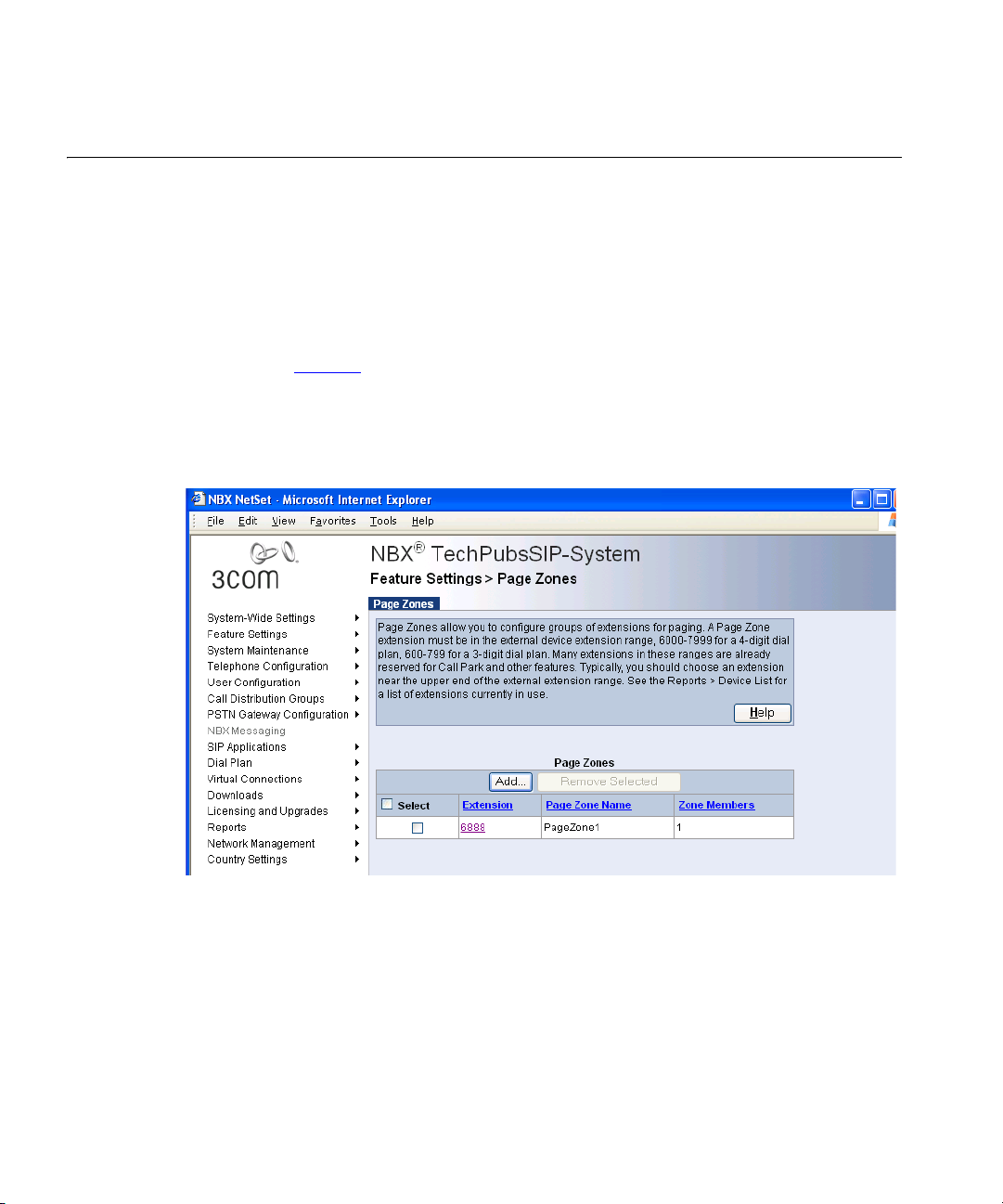
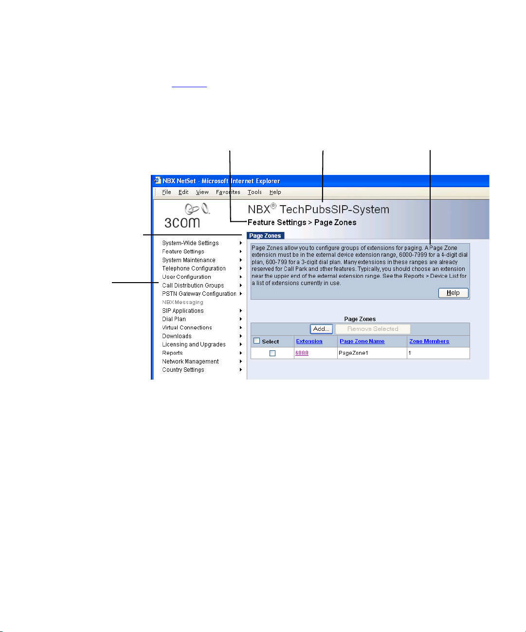
Figure 1 shows a sample NetSet window. The navigation menu is on the
left of the window. Place the cursor over any of the functions to expand
the view of that function and display all the associated options.
Figure 1 NetSet Utility - Page Zones Window
Systems present the NBX NetSet utility through an embedded web server
that is integrated in the system software. NetSet passwords grant system
administrators and telephone users different levels of access privileges.
Individual telephone users can view or change their personal settings,
such as personal speed dial lists, off-site notification settings, and ringing
tones. System administrators can manage user profiles and devices,
change system parameters, such as dial plan settings, and upgrade the
system software.
Page 25
NetSet Administration Utility 25
NetSet User Interface Figure 2 shows the NBX NetSet utility user interface. Each NetSet user
interface page contains common elements.
Figure 2 User Interface Elements
Title BarNavigation Route Bar Help
Tab Menu Bar
Navigation
Menu
■ Title Bar — The NBX trademark followed by the system (host) name.
■ Navigation Route Bar — The current page location, which is the
selected navigation menu item and the selected submenu item.
■ Navigation Menu — A list of all navigation groups in the NBX NetSet
user interface. The navigation menu is partially or fully disabled under
certain conditions. These conditions include:
■ System backup in progress: All menus are disabled.
■ System restore in progress: All menus are disabled.
■ System shutdown: All menus are disabled.
■ No system license: Only Licensing and Upgrades and System
Maintenance menus are enabled.
■ Tab Menu Bar — Displays when you click a menu item or submenu
item, or when you click a link to a record.
■ Help — Quick help text plus a button that invokes detailed help.
Page 26

26 CHAPTER 1: INTRODUCTION
Page 27

2
SYSTEM SETTINGS
This chapter provides information about how to configure settings,
whose effects span the entire system, and includes these topics:
■ Auto Discovery
■ Enable Features System-Wide
■ System Identity
■ Business Information
■ Date and Time
■ IP Settings
■ Audio Settings
■ Timers
■ Multicast Addresses
For more information about these topics and configuration procedures,
see the online Help.
Auto Discovery The Auto Discovery feature simplifies initial system configuration by
adding information about new devices to the configuration database.
Devices include telephones, Analog Line Card ports, Digital Line Card
channels, Analog Terminal Adapter ports, 3Com Attendant Consoles, and
virtual devices, such as the pcXset Soft Telephone and the ConneXtions
H.323 Gateway. Devices must have network connectivity with the Call
Processor.
After the system discovers a device, the Auto Discovery process does not
find that device again. To remove a device from the system database, use
the NBX NetSet utility to remove the device and its database record
manually. Note that if you delete a telephone user, the system does not
delete the device associated with that user.
Page 28

28 CHAPTER 2: SYSTEM SETTINGS
The system does not discover licensed devices until you enter the
appropriate Group License. For more information about Group Licensing,
see the NBX Installation Guide.
Ta bl e 4
summarizes Auto Discovery actions for system components.
Tab le 4 Auto Discovery Actions on System Components
Component Auto Discover Action
Analog Line Card and
V3000 analog line ports
Gathers configuration information from each port on the card, assigns a default
extension, and enters the information into the configuration database.
Digital Line Card Gathers configuration information from the card, assigns a default extension, and
enters the information into the configuration database.
After you Auto Discover the Digital Line Card, you might need to edit the dial plan to
configure Direct Inward Dial (DID) numbers.
3Com Telephones
Analog Terminal Cards
Analog Terminal Adapters
V3000 ATA port
Gathers configuration information from the telephone, assigns a default User Profile
labeled new user, assigns the next lowest available extension number to the profile,
and enters the information into the configuration database.
Auto Discover Telephones finds both Analog Terminal Cards and Analog Terminal
Adapters.
By default, the Auto Discover process assigns extension number 1000 (4-digit dial
plan) or 100 (3-digit dial plan) as the first telephone extension. You can use the NBX
NetSet utility to specify a new extension starting number. To simplify Auto Attendant
configuration, start a range at a base number, for example, 1000/100, 2000/200,
3000/300, or 4000/400. The default Auto Attendant assumes that extension 1000
(4-digit dial plan) or 100 (3-digit dial plan) is the extension of a human attendant
(receptionist).
3Com Attendant Console Finds and configures any installed 3Com Attendant Consoles. The system maps the
first 100 existing telephones, except for the extension that is associated with the
Attendant Console, to Attendant Console buttons. The lowest extension is
automatically associated with the Attendant Console. Typically, you enable Auto
Discover Attendant Consoles after you have installed all your telephones.
pcXset
Soft Telephone
Enables the Auto Discover feature on installations of the pcXset PC Telephone Client
when the following conditions are true:
■ The pcXset PC Soft Telephone program is running on the host PC.
■ The pcXset PC Soft Telephone host computer is connected to the network.
■ You have entered the proper license key into the NBX NetSet utility.
ConneXtions H.323 Gateway Configures line card port settings when the following conditions are true:
■ The ConneXtions H.323 Gateway program is running.
■ The ConneXtions H.323 Gateway host computer is connected to the network.
■ You have entered the proper license key into the NBX NetSet utility.
Page 29

Auto Discovery 29
Initial System
Configuration
To use the Auto Discover feature for initial system configuration:
1 Log in to the NBX NetSet utility using the administrator username and
password.
2 Click
System-Wide Settings > Enable Features System-Wide.
3 Verify that the Extensions Start At field is set to what you want, and then
click Apply.
For a 4-digit dial plan, extensions start by default at 1000. For a 3-digit
dial plan, extensions start at 100.
Do not specify a starting extension that begins with zero (0), which will
cause the Auto Discover process to fail.
4 Click
System-Wide Settings > Auto Discovery.
5 Select the check box for the device type that you are configuring and click
Apply.
3Com recommends that you Auto Discover one device type at a time. See
the online Help for detailed information about each field.
Auto Discovery Notes
■ If devices are on a different subnet from the Call Processor, enable IP
on the Call Processor (System-Wide Settings > IP Settings), and each
device must have IP configuration information.
■ You can use DHCP to configure the telephones. You must configure
the DHCP server to provide the Call Processor IP address through
option 184. Also, you can use the keypad to program IP settings into
each device. See “
Configuring Option 184 on a Windows 2000 DHCP
Server” on page 457 for DHCP information and “Using the Telephone
Local User Interface Utility” on page 413 for telephone local
programming instructions.
■ The Auto Discovery and software download processes might take a
few moments to complete. The Call Processor initializes devices one at
a time. If you have connected many new devices to the system at the
same time, the Auto Discovery process requires more time.
■ A fully initialized telephone displays its extension and the date and
time. If there are no extensions available, the Auto Discover process
fails, and the telephone’s display panel continues to display the
telephone’s MAC address.
Page 30

30 CHAPTER 2: SYSTEM SETTINGS
■ If you are adding devices that do not have a display panel, such as
■ If you are installing a 3Com Attendant Console, connect it after you
3100 Entry Telephones, connect the devices one at a time and then
refresh the Telephone Configuration > Telephones list after you
connect a device to see the extension assigned to that device.
have discovered all of the telephones. The Auto Discover Attendant
Consoles process maps all existing telephone extensions to the
Attendant Console.
Disabling the Auto
Discovery Feature
Enable Features System-Wide
After you finish the Auto Discovery process for the initial configuration,
disable Auto Discovery so that the Call Processor does not continue to
search for added devices.
To disable the Auto Discovery feature:
1 Log in to the NBX NetSet utility using the administrator username and
password.
2 Click
3 Clear all
4 Click
System-Wide Settings > Auto Discovery.
Auto Discover check boxes.
Apply.
From the System-Wide Setting page, you can make changes to these
settings.
■ Extensions Start at
■ External Prefix
■ RTP DTMF Payload Type
■ Caller ID Wait Timer
■ External Paging Delay
■ External Page Alert Volume
■ Handsfree on Internal Transfer / Camp On
■ Handsfree on External Transfer / Camp On
■ System-wide CLIR
■ One Button Transfer
■ Pulse Dialing
■ Supervisory Monitoring
Page 31

Enable Features System-Wide 31
■ Call Timer
■ Music On Hold
■ Music on Transfer
■ NBX Messaging
■ IP Messaging or Third-Party Messaging
■ URL for user access to IP Messaging or third-party messaging
■ Enable SIP
To configure system-wide settings:
1 Log on to the NBX NetSet utility using the administrator login ID and
password.
2 Click System-Wide Settings > Enable Features System-Wide.
3 See the online Help for detailed information about the settings and how
to modify them.
How Call Timer
Works With Other
Telephone Features
Ta bl e 5
summarizes how Call Timer works with other PBX-type features.
Tab le 5 Call Timer Behaviors
Feature Description
Internal Call The call duration displays on the originating telephone when the
telephone user finishes dialing the destination number. The call
time increments while the called number is ringing.
Call Timer does not work if the caller enters an invalid internal
extension.
External Call Call Timer behavior for an external call is the same as that of an
internal call except in these cases:
■ If the caller enters an invalid external number
■ If the telephone of the called number is busy
In these cases, the call time continues to advance.
Hold When you put a call on hold, the system hides the Call Timer
display. However, the Call Timer count continues to increment
during the time that the call is on hold. When you take the call off
hold, the Call Timer reappears.
Page 32

32 CHAPTER 2: SYSTEM SETTINGS
Tab le 5 Call Timer Behaviors
Feature Description
Transfer When you transfer a call, the Call Timer count does not carry
Conference
Call
Call Park Call Park behavior is similar to the Transfer feature. However, if the
Transfer
Through Auto
Attendant
Bridged Calls For bridged calls, the Call Timer display depends on the off-hook
forward to the transfer destination. However, during the time
period that the call is ringing on the transfer destination telephone,
the Call Timer count continues to increment on your telephone.
When the telephone user to whom you transferred the call answers
the call, that user sees the Call Timer count start from zero.
The Call Timer value on the telephone that originated the call
increments from the time at which the call originated.
The Call Timer value on each telephone that is added to the
conference increments from the time the conference participant
answered the phone.
If the conference originator drops other parties in the conference
and stays with one party at the end, the Call Timer is based upon
the total time the two parties spent in on the call, including any
time before or during the conference.
telephone that unparks the call is the same telephone that parked
the call, Call Timer displays the total time based on the time when
the telephone originated the initial call.
If the caller dials the main Auto Attendant number, and the Auto
Attendant transfers the call to the extension of choice (or to the
default destination), then the called party sees the same behavior as
if the call had been transferred. That is, the Call Timer count at the
transfer destination starts when the called party answers the call.
indicator.
Example: An administrative assistant answers the phone, and puts
the call on hold. Then, the a site manager picks up the call. The
manager sees the counter start from zero. However, if the
administrative assistant puts the call on hold and retrieves it later,
then the administrative assistant sees that the system has defined
the Call Timer display for normal hold.
Example: An administrative assistant puts a call on hold, and the
manager picks up the call and then puts it on hold. Then, the
administrative assistant picks up the call. In this case, the
administrative assistant sees the Call Timer display as if the
administrative assistant had picked up a new call.
Page 33

System Identity 33
System Identity The System Identity window shows the current system settings, such as
the software version, the IP address of the system, and the amount of
free memory. To view system settings:
1 Click System-Wide System Settings > System Identity.
Ta bl e 6
describes the System Settings fields.
Tab le 6 System Settings
Field Purpose
Software Version The call control software for the system.
System Serial # The serial number on the Call Processor circuit board.
Host Name This is an IP setting. It is a name you can give to the system
so you do not have to specify the IP address when you
access the NBX NetSet utility through a browser.
IP Address The IP address of the system.
Default Gateway The IP address of the destination host for any IP packet not
addressed to a host on the local subnetwork.
Subnet Mask An IP setting that identifies the network and host portions
of an IP address on the network.
Network Protocol The transport mechanism for voice packets.
Ethernet only: All communications are at the Ethernet
frame layer.
Standard IP: IP communications are used for traffic
between NBX system addresses. Every device needs an
IP address.
IP On-the-Fly: An implementation of IP communications in
which Layer 2 (Ethernet) devices temporarily use a Layer 3
(IP) address only when those devices need to communicate
with a Layer 3 device on a different subnetwork. The
system administrator defines an address pool that assigns
the IP address. After the Layer 2 device returns to the idle
state, the IP address returns to the pool of available
addresses for future use.
System MAC Address The hardware address of the system.
MOH MAC Address The hardware address of the Music-on-Hold (MOH) device.
Free Memory Available memory on the system.
Memory Upgrade
Installed
Indicates whether this system has had a memory upgrade.
Possible values are:
■ Yes (V3000, V5000 systems)
■ No (V3000, V5000 systems)
■ N/A (NBX 100, V3001R systems)
Page 34

34 CHAPTER 2: SYSTEM SETTINGS
Tab le 6 System Settings (continued)
Field Purpose
File System The file system this system uses.
Date and Time The current system date and time. To modify, click
System Start Time The last time you initialized the system (boot time).
■ NBXFSV1 - The pre-release R6.0 file system.
■ NBXFSV2 - The newer file system that is shipped with
release R6.0 or higher systems, which offers better
performance and upgrade capabilities.
If you upgrade an existing system to release R6.0, the
system continues to use NBXFSV1.
System-Wide Settings > Set Date and Time.
Business Information
System Mode The System Mode window lets you specify that the system operate in a
You can configure information about the your business, such as business
address and hours, including time of day service modes. You can also
view the current mode and force the system into a different mode.
To enter business information:
1 Log on to the NBX NetSet utility using the administrator login ID and
password.
2 Click System-Wide Settings > Business Information.
3 See the online Help for procedures to modify these types of information:
■ Business information
■ Business hours
■ System mode
Click the Business Identity tab to display the information that you
configure in the Business Information, Business Hours, and System Mode
windows.
particular mode or automatically. If necessary, you can force the system
into a specific Time of Day Service mode without changing other system
settings, such as Business Hours. If the system is in Automatic mode, it
constantly compares the current time of day and day of week with the
settings you establish in the Business Hours window (click System-Wide
Settings > Business Information and click the Business Hours tab).
Page 35

Date and Time 35
Business Hours The Business Hours window allows you to define business hours for three
separate service modes: Open, Lunch, and Other. Any time period that
does not fall within these specified hours is considered Closed. Business
hours link directly to time-of-day service modes and can affect other
settings in the system, such as the Auto Attendant.
If the system mode is set to Automatic, the system constantly compares
the current time of day and day of week with the business hour tables.
The system knows the current day of the week and proceeds across the
tables in a sequential manner, looking for business hours that match the
current time of day. The system examines the three tables sequentially:
first the Other mode, then the Lunch mode, and then the Open mode.
The system moves across the tables until it finds a match. It skips a blank
table.
Date and Time The Date and Time window allows you to configure the following:
■ System Date and Time
■ Simple Network Time Protocol (SNTP)
System Date and
Time
Make sure the system date and time are accurate because it affects these
system features:
■ The 3Com telephone display panel
■ Business hours behavior
■ Time-dependent prompts in the Auto Attendant
■ Time and date stamp on voice mail
To access the date and time settings in the NBX NetSet utility:
1 Log on to the NBX NetSet utility using the administrator login ID and
password.
2 Click System-Wide Settings > Date and Time.
3 See the online Help for the procedure to set the system date and time.
If you enter the system time and select a new time zone simultaneously,
(that is, you do not apply the system time first) the system automatically
adjusts the system time you entered to correspond to the selected time
zone. For example, if the system time is set to 6:00 AM US Pacific, select
the US Pacific time zone and allow the system to adjust the time
Page 36

36 CHAPTER 2: SYSTEM SETTINGS
automatically. If you enter 6:00 AM and then select the US Pacific time
zone, the system adjusts the system time based on 6:00 AM and displays
the system time as 3:00 AM US Pacific.
Simple Network Time
Protocol (SNTP)
The Simple Network Time Protocol (SNTP) synchronizes CPU clocks across
the Internet. SNTP belongs to the TCP/IP suite and works at the
Application layer in the OSI model, and uses UDP port 123 for
communication. SNTP Version 4 can operate in either unicast (point to
point), multicast (point to multipoint), or any cast (multipoint to point).
If you need to coordinate your system time with other Internet devices,
use the NBX NetSet utility to synchronize the system to an SNTP server at
a specified interval.
The initialization process initializes the SNTP client and connects to an
available SNTP server. The SNTP server provides the time, which the
system uses. When the synchronization interval expires, the system
synchronizes with the SNTP server again. Any changes to the SNTP
configuration take effect when the synchronization interval expires.
The system uses the time provided by the SNTP server for all references to
local time. This includes the time stamps used by the Call Processor,
phones, and gateways.
If the SNTP server fails, you can configure the system to transfer server
control to another active SNTP server in the list. (You have the option to
identify up to three SNTP servers to the system).
See the online Help for information about the procedure to configure the
system to use SNTP.
IP Settings The IP Settings window allows you to define the network protocol
settings for this system and, if you are using IP On-The-Fly, to define the
range of IP addresses that the system can use to assign addresses to
devices as needed.
Before you configure the IP settings, you must have all necessary network
information, such as the network protocol, VLANs, Layer 3 IP information
about this Call Processor, and any DNS server addresses. This information
is propagated in the IP Settings window.
The IP Address Ranges window allows you to add or delete a range of IP
On-the-Fly addresses.
Page 37

Audio Settings 37
Audio Settings Audio Settings enable you to affect the network impact of your audio
packets by enabling or disabling compression and silence suppression.
You can enable and disable these settings for the entire system and then
override the system-wide setting for individual devices.
Compression
Overview
Before voice traffic can be transmitted over a digital network, the audio
waveform, an analog signal, must be encoded into a digital format. The
digitized audio is packetized and delivered over the network to a
destination, and then decoded back into a voice waveform. Software
called a codec (coder/decoder) converts the audio information between
digital and analog formats.
Digitized audio formats have different properties. Each format represents
a compromise between bandwidth and audio quality, that is, high quality
audio typically requires more network bandwidth. Compressing the
digitized audio data can conserve bandwidth with little compromise in
audio quality, but compression requires increased processing overhead
when encoding and decoding the audio information. Too much
processing overhead can introduce delay.
Ta bl e 7
lists the codecs that the system supports and describes the
characteristics of each one.
.
Tab le 7 Supported Codecs
Codec Description
G.711
No Compression
ADPCM
Medium
Compression
G.729
High
Compression
An International Telecommunications Union (ITU) standard for
audio encoding. Encoding and decoding is fast and support is
widespread. Also called MULAW or µLAW. A-law is a slight
variation, which European telephone systems use. G.711
provides high quality audio at 64 kbps. Telephone companies
worldwide use G.711 encoding to provide “toll-quality audio.”
Adaptive Differential Pulse Code Modulation (ADPCM) provides
good quality audio at a lower bitrate (32 kbps) than G.711. The
system uses the International Multimedia Association (IMA)
version of ADPCM.
G.729, an ITU standard, employs a more sophisticated
compression technique than ADPCM and it is supported
worldwide. The G.729A codec compresses the audio information
to 8 kbps, although processing overhead results in actual
bandwidths greater than 8 kbps.
Page 38

38 CHAPTER 2: SYSTEM SETTINGS
Tab le 7 Supported Codecs
Codec Description
G.722
G.722.2
G.722.2LB
Wideband Audio
Codec Selection It is important to remember not to select a codec based on compression
alone. Consider the trade-off between audio quality and bandwidth use.
System-Wide Audio
For system-wide audio, base the default list order on audio quality:
G.722.2 is an ITU-T standard for wideband voice applications and
services. G.722.2 is an adaptive multi-rate wideband codec that
uses bit rates ranging from 6.6 to 23.85 kbps.
G.722 is an SB-ADPCM (sub band Adaptive Pulse Code
Modulation) codec. It runs ADPCM on both the low band (0 4000 Hz) and the high band (4000 - 8000). The raw bit rate
(without network packet headers) is 64 kbps.
G.722.2 is a CELP (code excited linear prediction) based codec.
G.722 is a 23.85 kbps rate. G.722.2 LB has a rate of 8.85 kbps.
The standard was originally designed for wireless networks and
the different rates allow for adapting to varying channel
conditions.
Tab le 8 Default Order List Based on Audio Quality
Codec Quality Bandwidth
G.722.2 best quality medium bandwidth
G.722 high quality high bandwidth
G.711 good quality high bandwidth
G.722.2LB good quality low bandwidth
G.729 medium quality low bandwidth
ADPCM low quality medium bandwidth
VTL Calls Audio
For Virtual Tie Line (VTL) audio, base the default list order on bandwidth
usage:
Tab le 9 Default Order List Based on Bandwidth Usage
Codec Quality Bandwidth
G.722.2LB good quality low bandwidth
G.729 medium quality low bandwidth
Page 39

Audio Settings 39
Tab le 9 Default Order List Based on Bandwidth Usage
Codec Quality Bandwidth
G.722.2 best quality medium bandwidth
ADPCM low quality medium bandwidth
G.722 high quality high bandwidth
G.711 good quality high bandwidth
Custom Audio
For custom audio that you determine based on the needs of your site,
you can choose the list order:
Table 10 Default Order List Based on Bandwidth
Codec Quality Bandwidth
G.729 medium quality low bandwidth
G.722.2 best quality medium bandwidth
ADPCM low quality medium bandwidth
G.722.2LB good quality low bandwidth
G.722 high quality high bandwidth
G.711 good quality high bandwidth
For the audio settings that are configured on each device, 3Com provides
sorted lists such as these. Each list contains the codecs supported for that
device only.
For example, a default codec configuration list for a 3Com Business
Telephone (that is, sorted by audio quality) might show a codec
configuration list like the following:
G711 good Q high BW
ADPCM low Q med BW
If you have set device options for a low bandwidth connection, then the
3Com Business Telephone codec configuration list might show:
ADPCM low Q med BW
G711 good Q high BW
Page 40

40 CHAPTER 2: SYSTEM SETTINGS
When the system negotiates which codec to choose, the process starts
from the top of the list and queries devices to discover if they support the
codec. If the device is supported, the system chooses the codec;
otherwise, the system goes on to the next codec in the list and initiates
the query process.
Codecs and NBX
Devices
Codecs reside on the NBX devices — telephones, analog terminal
adapters, and so forth. Some older devices do not support the latest
codecs. Therefore, during call setup, NBX devices negotiate an encoding
scheme that both devices (or all devices on a conference call) support.
Ta bl e 1 1
lists each device that must encode or decode audio, and shows
how each device supports the available codecs. Certain devices are
marked “N/A” for the G.722 codecs because those codecs are for
wideband audio, which is not supported by wide area networks or across
the PSTN.
Table 11 Audio Encoding Supported by NBX Devices
Device Part Number G.729 ADPCM G.711 G.722 G.722.2
3Com 1102, 2102, and 2102-IR
Business Telephones
3Com 2101 Basic Telephones 3C10248PE
3Com 3100 Entry Telephone 3C10399A Yes Yes Yes No No No
3Com 3101, and 3101SP Basic
Telephones
3Com 3101B Basic Telephone 3C10401B Yes Yes Yes Yes Yes Yes
3Com 3101SPB Basic Telephone 3C10401SPKRB Yes Yes Yes Yes Yes Yes
3Com 3102 Business Telephone 3C10402A Yes Yes Yes No No No
3Com 3102B Business Telephone 3C10402B Yes Yes Yes Yes Yes Yes
3Com 3103 Manager’s
Telephone
3Com 3106C and 3107C
Cordless Telephones
3C10121 3C10122
3C10226A
3C10228IRA
3C10226PE
3C10226B
3C10228IRPE
3C10228IRB
3C10281PE
3C10281B
3C10248B
3C10401A
3C10401SPKRA
3C10403A Yes Yes Yes Yes Yes Yes
3C10406C
3C10407C
No Yes Yes No No No
Yes Yes Yes No No No
Yes Yes Yes No No No
Yes Yes Yes No No No
Yes Yes Yes No No No
G.722.2LB
Page 41

Table 11 Audio Encoding Supported by NBX Devices (continued)
Audio Settings 41
Device Part Number G.729 ADPCM G.711 G.722 G.722.2
3Com 3108 Wireless Telephone 3C10408A Yes Yes Yes No No No
Analog Terminal Adapter 3C10120
3C10120B
3C10400 Yes Yes Yes N / A N / A N / A
Analog Terminal Card 3C10117
3C10117B-INT
3C10117C Yes Yes Yes N / A N / A N / A
Analog Line Card 3C10114
Digital Line Card 3C10116,
Silence Suppression
Overview
3C10114-ANZ
3C10114C Yes Yes Yes N / A N / A N / A
3C10116B
3C10116C
3C10164-ST (BRI)
3C10164C-ST (BRI)
3C10165
3C10165C
3C10116D
3C10165D
Silence suppression is a method of reducing the number of packets
transmitted during a conversation. Silence suppression can help you avoid
No Yes Yes N / A N / A N / A
No Yes Yes N / A N / A N / A
No Yes Yes N / A N / A N / A
No Yes Yes N / A N / A N / A
Yes Yes Yes N / A N / A N / A
G.722.2LB
dropped packets on a congested network. During a conversation there
are periods of silence. A packet of silence takes up as much bandwidth as
a packet with audio data. If you enable Silence Suppression, the
telephone sends a silence indicator when it senses the start of a silent
period and it suppresses all subsequent voiceless frames. When another
NBX device receives this indicator, it generates and inserts white noise
until it receives the next frame that contains audio data. If you enable
Silence Suppression, a careful listener might notice a difference in audio
quality. The background white noise generated by the receiving
telephone is subtly different from the silence in an audio stream.
Silence suppression results in compromises to audio quality. Do not
enable suppression unless you are trying to solve network bandwidth
congestion issues that you cannot solve through other means, such as
increasing network capacity.
To enable Silence Suppression, click System-Wide Settings > Audio
Settings.
Page 42

42 CHAPTER 2: SYSTEM SETTINGS
Timers System timers enable you to set time-out periods for the system features
that are described in Tab le 1 2
To set timers:
1 Log on to the NBX NetSet utility using the administrator login ID and
password.
2 Click System-Wide Settings > Timers.
Table 12 System Timers
Field Purpose
Forward Voice
Mail On
Timeout
Forward Voice
Mail Off
Timeout
Line Port Hold
Timeout
Call Park
Timeout
Conference
Timeout
Transfer
Timeout
When a telephone’s Forward to Mail feature is enabled, sets the
duration of ringing before the system forwards a call to voice mail.
NOTE: If you set this time to be less than six seconds, Caller ID
information is not captured in voice mail.
When a telephone’s Forward to Mail feature is disabled, sets the
duration of ringing before the system forwards a call to voice mail.
The system uses this setting as the default for each new telephone
user that you add to the system. If you modify this value, users
added after the change use the new value as the default.
Telephone users added prior to the change are unaffected.
Individual telephone users can modify the default setting in the Call
Forward window of the User interface of the NBX NetSet utility by
specifying the number of times the telephone rings before the
system forwards a call.
For a call that originated on an outside line, the length of time that
the call remains on hold before it rings at the extension that placed
the call on hold.
The length of time that a call can be parked before it rings at the
extension that parked the call.
The length of time before the system abandons a conference
attempt. Applies to a blind conference only. The timeout takes
effect under these conditions:
■ Two people, A and B, are involved in a call and one of them
attempts to blind conference another person, C.
■ C does not answer and C’s voice mail does not pick up the call.
After the Conference Timeout period, the system stops ringing C’s
telephone, stops attempting to conference with C, and reverts to
the call between A and B.
The length of time that a transferred call attempts the transfer
before it rings at the extension that transferred the call.
.
Page 43

Table 12 System Timers
Field Purpose
TAPI Line
Redirect
Timeout
Camp On
Timeout
Automatic
Callback
Timeout
The length of time before a call redirected from a TAPI route point
by an external application returns to its original destination. After
two failures, the call goes to the TAPI route point’s call coverage
option.
TAPI Line Redirect allows an external TAPI application, typically a
call center application, to reroute incoming calls based on caller ID
information automatically.
For more information, see TAPI Route Points.
The length of time that a call can camp on a busy extension before
the system returns the call to the extension that initiated the Camp
On feature.
The Camp On Timer can be set in increments of 10 seconds. The
default value for Camp On Timer is 180 seconds. The maximum
value that you can set the timer for is 600 seconds.
The length of time that a call can be designated for call back
before the system cancels the call.
The Callback Timer has default value of 12 hours. You can set the
timer to have a null value. If Automatic Callback is not returned in
the specified time, Automatic Callback is cancelled. A system
reboot also cancels the Automatic Callback on an extension.
Multicast Addresses 43
Multicast Addresses The system uses IP multicast addressing to distribute information for
these system features, which are available on Layer 2 and Layer 3 IP
devices:
■ Mapped line appearances
■ Internal pages
■ External pages
■ Conference calls
The Music on Hold (MOH) feature is available on Layer 2 devices only. The
IP implementation uses Internet Group Management Protocol (IGMP)
to transmit and distribute the necessary data and audio.
If you configure your system to use IP On-the-Fly or Standard IP and your
switches use IGMP Snooping, you must have an IGMP Host on the
network. Typically, an IGMP Host is an IP Multicast Router or a switch that
has IGMP Query capability.
Page 44

44 CHAPTER 2: SYSTEM SETTINGS
The system IGMP is an implementation of administratively scoped
IP multicast that uses three scopes of administration:
■ Local scope — Limited by local routers with IP addresses 239.255.0.0
■ Organizational local scope — Limited by boundary routers with
■ Global scope — IP addresses 224.2.0.0 through 224.2.127.253
IGMP might not be available in all systems or network topologies. All
routers between the various components must support IGMP and the
necessary router protocols to establish a path for the IP multicast packets.
Each event that occurs in an IGMP setup, such as taking a telephone off
the hook, causes a packet of 200 Kb to 300 Kb to be sent.
The default settings for the IP multicast addresses function in most
network environments. Certain addresses are reserved.
The MAC address and the IP address displayed on any one line of the
Multicast Address List window are not related.
through 239.255.0.16
IP addresses 239.192.0.0 through 239.192.0.14
There are two methods for selecting multicast addresses:
■ Change IP — Lets you select a starting address for all entries.
Changing IP multicast addresses is a quick way to change the range of
system multicast addresses to avoid conflicts with other equipment on
your network.
■ Change bins — Lets you change a single entry by selecting from a list
of available bins. Changing IP bins is useful for changing a single
address that might conflict with another system device. Consult your
network administrator to determine which address is in conflict and
the new address to choose.
To change multicast addresses:
1 Log on to the NBX NetSet utility using the administrator login ID and
password.
2 Click System-Wide Settings > Multicast Addresses.
3 See the online Help for more information.
Page 45

3
FEATURE SETTINGS
This chapter provides information about configuring the system to take
advantage of system features. It describes these topics:
■ Account Codes
■ Call Pickup
■ Call Park
■ Page Zones
■ Ring Patterns
■ Supervisory Monitoring
■ Speed Dials
■ WhisperPage
For more information about these topics and configuration procedures,
see the online Help.
Account Codes Account codes are additional numbers that telephone users dial to
associate calls with specific functions, sources, or destinations. For
example, call center operations often employ account codes to associate
calls made by Automatic Call Distribution (ACD) agents with their
relevant accounts for tracking purposes. (See Chapter 7
more information about ACD.) Telephone users enter an account code
while placing a call or during a call.
Verifying account codes is a global configuration setting, while enforcing
account codes is a per-Class of Service (CoS) setting. If the CoS setting
enforces the account code for that particular type of call, a telephone
user must enter an account code before the system routes the call.
The enforced account code does not apply to internal or emergency (911)
calls.
in this guide for
Page 46

46 CHAPTER 3: FEATURE SETTINGS
Account codes range from two to sixteen digits. The system allows up to
5000 account codes.
The system maintains a centralized list of account codes that you can
update, and can verify the account codes that telephone users enter
against this list of account codes.
Account codes are classified by four operation modes, which determine
how strictly to enforce account code usage for outgoing calls based on
Class of Service criteria. See the Account Codes: Operational Modes
section of this chapter for information about operational modes.
Feature Interaction This section describes the ways in which account codes interact with
other features.
Bridged Station Appearance
Only a primary telephone can originate a call. However, once the call is
answered, either the primary or the secondary telephone can place the
call on hold and take it off hold. The last account code that the primary or
the secondary telephone entered overrides the account code for the call.
CO Flash
The system does not enforce account code entry for calls that you
originate by means of a CO Flash. This means that you can receive a call,
perform a CO Flash, and make an external call without entering an
account code.
Conference
During the time that forced account code mode is enabled, you must
enter an account code for each leg of a conference. The account code
applies to the call leg, and not to the call from which the conference is
initiated. After the conference is completed, an account code entered by
any telephone user overrides the account code for the conference call.
Emergency Numbers
The system allows emergency numbers without an account code.
Page 47

Account Codes 47
Call Forwarding
You cannot specify account codes as part of a forwarding number. If you
forward a call while forced account code entry is enabled, the call is
forwarded and you are not prompted to enter an account code. A side
effect of this feature interaction is that an internal extension could be
used to forward calls to an external number and thereby circumvent
forced account code entry.
International Dialing
If you enabled Force mode and a timeout occurs after you have entered
the minimum number of digits and are still dialing, the system prompts
you to enter an account code. After you enter the account code, you can
continue entering digits for the international number.
Paging
You can use Paging without entering an account code.
Call Park
If you entered an account code before you park a call, that call is
preserved when you unpark it. You can unpark calls without entering an
account code. You can enter a new account code after unparking the
call.
Redial
Account codes are not stored as part of the redial digits (except on analog
phones), even if you specified the account code as part of a speed dial
operation. If outbound digits are redialed while forced account code
mode is enabled, the system prompts you to enter an account code.
Speed Dial
Phones with programmable buttons and Attendant Consoles can use
speed dial with account codes. From the User interface of the NBX NetSet
utility:
■ Configure a one-touch speed dial with an account code. Click
Directory and then the One-Touch Speed Dial tab. Use the following
format in the Number field:
[888] + Account code + # + Outbound number
Page 48

48 CHAPTER 3: FEATURE SETTINGS
■ Configure a personal speed dial with an account code. Click Directory
For security reasons, the telephone’s display panel does not display the
account code during a speed dial. If the account code is valid, the display
panel displays the account name.
Call Transfer
If you enable Forced mode, when you transfer a call, enter an account
code before the second call is routed. After the transfer is complete, the
account code entered on the second call leg also applies to the
transferred call.
This means that the first call (prior to the start of transfer) can have
account code XXX, the second call (prior to the completion of the
transfer) can have account code YYY, and the transferred call has account
code YYY.
You must use brackets, which indicates that 888 is a feature code.
and then the Personal Speed Dial tab. Supply the account code
separately in the Account Code field.
Account Codes:
Operational Modes
VTL
Forced account code entry applies to all VTL calls.
Before you configure account codes for your system, make sure you are
familiar with the enforcement and verification mechanisms and how they
affect your call operations.
Codes are classified by one of the these modes:
■ Forced / Verified Mode
■ Forced / Unverified Mode
■ Unforced / Verified Mode
■ Unforced / Unverified Mode
Forced / Verified Mode
In Forced / Verified mode, the system first forces the telephone user to
enter an account code and verifies that the code is correct before routing
an outgoing call. The system verifies the account code against a master
list that you establish.
Page 49

Account Codes 49
To place an outgoing call, dial the outbound number in either of the
following ways:
■ Outbound number + # + Account code + #
■ Feature + 888 + Account Code + # + Outbound number
In the first instance, you might not know or remember that an account
code is necessary and dial only the outbound number. In this case, the
telephone prompts you to enter an account code after a short period of
time.
If the account code is valid, the Feature Success tone plays and the system
routes the call.
If the account code is invalid:
■ On a telephone with a display panel, the display panel displays the
invalid account code and prompts you to enter the account code
again. After three unsuccessful attempts to enter the account code,
you must start over by reentering the outbound number and account
code.
■ On a phone without a display panel, the telephone plays the Feature
Error tone and you must reenter the entire digit sequence.
The system does not require account codes for emergency calls, such as
911, and immediately routes the calls.
During the call, you can enter another valid account code using the
following format:
F+ 888 + Account_code + #
You can enter multiple account codes during a call; the most recently
entered account code overrides the previously entered account code. In
Verified account code mode, the newest account code only overrides the
existing account code if it has been verified.
The account code and account name information is available in the Call
Detail Reporting (CDR) data. To download the NBX Call Reports software,
click Download > Applications. To enable CDR, click System Maintenance
> Call Report Settings.
Enforcing account codes is applicable for outgoing external calls only.
Page 50

50 CHAPTER 3: FEATURE SETTINGS
Forced / Unverified Mode
Forced / Unverified mode is similar to Forced / Verified mode in that the
system forces you to enter an account code. However, because the
system does not verify the account code, the telephone either:
■ Displays the account name associated with the code.
■ Displays the text string Unknown Account.
In this mode, it is possible for you to enter an invalid account code and
still proceed with the call.
The account code and account name information is available in CDR.
The system only forces the use of account codes on outgoing, external
calls.
Unforced / Verified Mode
In Unforced / Verified mode, the system does not force you to enter an
account code. However, if you do enter an account code, the system
verifies that the account code is correct.
You can enter an account code during the call using the following
format:
Feature + 888 + Account_code + #
The system verifies the account code against the list of valid account
codes.
■ On a telephone with a display panel, an invalid account code shows
the text string
■ On a telephone without a display panel, an invalid account code plays
Unknown Account, and the call continues.
the Feature Error tone, and the call continues.
Unforced / Unverified Mode
Unforced / Unverified mode is similar to Unforced / Verified mode, but the
system does not verify the account code. The telephone displays the
account name if the account code is valid and the call continues.
The account code and account name information is available in CDR.
Page 51

Call Pickup 51
Configuring Enforcement and Verification
To enable or disable verification of outgoing calls:
1 Log in to the NBX NetSet utility using the administrator login ID and
password.
2 Go to Feature Settings > Account Codes.
3 Enable the check box next to the appropriate account code (or create a
new one before proceeding).
4 Enable or disable the Enforce account codes verification check box, as
appropriate.
5 Click Apply.
To enforce or relax the need for an account code:
1 Log in to the NBX NetSet utility using the administrator login ID and
password.
2 Click User Configuration > Class of Service.
3 Click the appropriate CoS Group name, which displays the Modify
window.
4 Locate the appropriate Class of Service (such as International or Long
Distance), then enable or disable the corresponding Force Acct Code
check box.
5 Repeat the previous step for each appropriate Class of Service.
6 Click Apply to activate the changes and leave this window open, or click
OK to activate the changes and close this window.
Call Pickup Call Pickup allows telephone users who hear a telephone ringing to
answer the call on their own telephones. To enable this feature, you add
telephone extensions to Call Pickup Groups.
The Call Pickup feature is not supported for hunt groups. However, it is
supported for ACD groups.
Group Numbers Ta bl e 1 3
summarizes the Call Pickup group numbers.
Page 52

52 CHAPTER 3: FEATURE SETTINGS
Table 13 Call Pickup Group Numbers
System Group Numbers
V3000, V3001R, V5000 50 Call Pickup groups:
NBX 100 32 Call Pickup groups from group 0 (extension 500)
See the NBX Telephone Guide for user instructions about how to use Call
Pickup.
If you select Auto Add Phones to Call Pickup Group 0 (System-Wide
Settings > Auto Discovery), every telephone that you add to the system is
a member of Call Pickup group 0 (extension 500). Any telephone can pick
up calls to a telephone user who is a member of default Call Pickup
Group 0. Telephone users can add or remove their own telephone
extensions from the group to allow or prevent others from picking up
their calls. See the NBX Telephone Guide and the User online Help for
more information.
■ Group 0 through group 31 (extension 500 through
531)
■ Group 32 through group 49 (extension 482 through
499)
50 Directed Call Pickup groups (extension 540 through
589)
through group 31 (extension 531)
10 Directed Call Pickup groups from 540 through 549
You can add telephone users to and remove them from any of the
groups. Telephone users can remove themselves from Call Pickup group
0, but not from any other Call Pickup groups.
You can map Call Pickup Groups to user telephone buttons to provide
one-touch access to the Call Pickup groups. See “
Creating and Managing
Button Mappings” in Chapter 5.
To configure call pickup groups and modify group membership:
1 Log on to the NBX NetSet utility using the administrator login ID and
password.
2 Click Feature Settings > Call Pickup.
3 See the online Help for more information.
Page 53

Call Park 53
Call Park When you park a call, anyone can retrieve it from any other telephone in
the system by entering the Call Park extension that is associated with that
call.
Example: You need to transfer an incoming call, but the person that you
need to reach is not available. You can park the call on any unused Call
Park extension, and then page the person and announce that Call Park
extension. The person can then dial the Call Park extension from any
internal telephone to retrieve the parked call.
These are the default system configuration extensions for Call Park:
■ 4-digit dial plan: 6000 through 6099
■ 3-digit dial plan: 601 through 609
Adding a Call Park
Extension
Changing a Call Park
Extension Name
Removing a Call Park
Extension
To add a Call Park extension:
1 Click Feature Settings > Call Park.
2 Click Add.
3 Enter the number of an extension in the Extension field.
4 Enter a name for the extension in the Name field.
5 Click OK.
To change the name of a default Call Park extension:
1 Click Feature Settings > Call Park.
2 Click an extension.
3 Enter the new name for the Call Park extension in the Name field.
4 Click OK.
You can remove a Call Park extension at any time:
1 Click Feature Settings > Call Park.
2 Select the extension, or extensions, that you want to delete and click
Remove Selected. To select all extensions, enable the Select check box.
3 Click OK.
Page 54

54 CHAPTER 3: FEATURE SETTINGS
To replace any extension that you remove, see “Adding a Call Park
Extension” on page 53.
Page Zones The Page Zone feature allows you to designate a subset of devices within
the system as members of a zone. Telephone users then can page
members of that group only, rather than paging all devices on the system.
The system supports up to 16 page zones per system.
The system allows multiple simultaneous zone pages. However, a device
that is currently paging or being paged will not respond to another page
request.
A Page Zone extension must be in the external device extension range:
■ 6000-7999 for a 4-digit dial plan
■ 600-799 for a 3-digit dial plan
The default 3- and 4-digit dial plans assign extension numbers that start
with 7 as diagnostic. Diagnostics is a Class of Service that you can assign
to a telephone user. For example, if you want to assign a page zone to
extension 720, either change the dial plan (to make 7** an internal call)
or assign the CoS permissions labelled Diagnostics to users who will be
dialing the 720 page zone. To keep the dial plan and CoS defaults, use
the extension range of 6000 – 6999 (or 600 – 699) for page zones.
Page Zone Feature
Support
Many extensions in these ranges are already reserved for Call Park and
other features. Typically, you choose an extension near the upper end of
the external extension range. Click Reports > Device List for a list of
extensions currently in use.
The Page Zone feature supports the following features and desktop
applications:
■ Caller ID — The display panel on the device originating the zone page
displays the zone page’s name and extension; the recipients’ display
panels do not display the broadcaster’s extension.
■ Hands Free — A zone page reaches a device that has Hands Free
enabled.
■ Hold — A zone page reaches a device that has Hold enabled.
Page 55

Ring Patterns 55
■ Speed Dial (Personal) — A device is able to store personal speed dial
extensions as zone page extensions.
■ Speed Dial (System) — A device is able to store system speed dial
extensions as zone page extensions.
All other features and desktop applications are not supported. A zone
page does not reach a device that has Do Not Disturb enabled.
When zone paging, you cannot include devices from a different Call
Processor in a local page zone. However, if your dial plan is configured to
support Virtual Tie Lines (VTLs), you can include an extension on a
different Call Processor in a zone page.
SIP telephones can neither initiate nor receive pages.
To configure Page Zones:
1 Log on to the NBX NetSet utility using the administrator login ID and
password.
2 Click Feature Settings > Page Zones.
3 See the online Help for information about how to add, modify, and
remove page zones.
Ring Patterns You can set system-wide ring patterns, such as one, two, or three rings,
to distinguish between internal and external calls.
Do not confuse ring patterns with ringer tones, which telephone users
can set for their telephones from the NBX NetSet utility. For information
about setting a telephone user’s ringer tones, see the NBX Telephone
Guides or the User online Help.
To set ring patterns:
1 Log on to the NBX NetSet utility using the administrator login ID and
password.
2 Click Feature Settings > Ring Patterns.
3 See the online Help for more information.
Supervisory Monitoring
Supervisory Monitoring allows a supervisor to monitor calls on the
system, with or without the knowledge of the parties engaged on the
Page 56

56 CHAPTER 3: FEATURE SETTINGS
call, as a part of the quality control operations of a site. Typically, you
monitor or audit calls that are routed through ACDs, Hunt Groups, or
TAPI Route Points. However, you can monitor any call.
This section describes these topics:
■ Introduction to Monitoring
■ Domains and Privacy
■ Announcement Tones and Supervisory Modes
Introduction to
Monitoring
Supervisory Monitoring takes place through domains. A domain is a
collection of telephone users who are grouped because they are logically
related in some way. In this case, the telephone users in a domain are
candidates for monitoring. If you enable Supervisory Monitoring in a
domain, each telephone user in that domain can be monitored.
By default, Supervisory Monitoring is disabled. You can enable or disable
Supervisory Monitoring on a system-wide basis. Click System-Wide
Settings > Enable Features System-Wide and then enable the Supervisory
Monitoring check box.
There might be situations in which a telephone user’s calls need not be
monitored. In this case, the Privacy List domain is a special domain that
contains telephone users whose calls cannot be monitored.
A monitoring session, in which an agent’s call is actively monitored,
includes:
■ The supervisor, or monitoring party, who is any telephone user in the
system who knows the Supervisory Monitoring domain password and
thus can monitor the members of the domain associated with that
password.
■ The agent, who is any telephone user who is part of a supervisory
monitoring domain and who a supervisor in that domain can monitor,
unless that telephone user is in the Privacy List domain.
The actual audio state, or mode, of the session might be one of the
following:
Page 57

Supervisory Monitoring 57
Table 14 Supervisory Monitoring Modes
Mode Description
Monitor Enables a supervisor to monitor a call with or without the
knowledge of the agent or the external party (typically a
customer).
Whisper Enables a supervisor to coach or speak with an agent without
the customer's knowledge.
Barge-In Enables the supervisor to speak with both the agent and the
customer.
You can configure announcement tones to allow the agent or the
customer, or both, to know that the call is being monitored.
Domains and
Upgrades
Supervisory Monitoring domains are a new feature in release R6.0. To
create and manage Supervisory Monitoring domains, click Feature
Settings > Supervisory Monitoring and see the online Help for more
information.
If you upgrade to release R6.0 from a previous release, make sure you are
aware of upgrade results.
Release R5.0 supported Supervisory Monitoring for calls that hunt
groups, ACD groups, and route points managed. When you upgrade a
release R5.0 system to release R6.0, the system creates new Supervisory
Monitoring domains automatically for all existing groups for which the
Supervisory Monitoring passwords were changed from the default
setting. If a group’s default password was not changed in release R5.0,
the system does not create a new Supervisory Domain for that group.
The new Supervisory Monitoring domains have these characteristics:
■ The upgrade process transfers all relevant information from release
R5.0 groups to the new release R6.0 Supervisory Monitoring domains.
For example, the members of a new Supervisory Monitoring domain
are the same members of the Hunt Group or the ACD Group that you
created in release R5.0.
■ The name of each new Supervisory Monitoring domain that the
system creates during the upgrade process is the group name plus the
group number of the Hunt Group or the ACD Group that had
Supervisory Monitoring enabled. The new password is the group’s
extension plus the former supervisory monitoring password. For
Page 58

58 CHAPTER 3: FEATURE SETTINGS
example, if ACD Group 4000 had password 1234 in release R5.0, the
new Supervisory Monitoring domain password in release R6.0 is
40001234.
■ The tones that are enabled for a new Supervisory Monitoring domain
are the same tones that were in effect for the Hunt Group or ACD
Group before the upgrade.
■ The call type settings default to incoming group calls only.
Domains and Privacy Be aware of the following privacy issues when you use Supervisory
Monitoring on your system:
■ Monitoring Ability
A supervisor can monitor:
■ All call types, which includes incoming, outgoing, and non-ACD
calls.
■ Anyone in the system.
■ Three-party conference calls. The supervisor counts as one of the
parties in a conference, which supports up to four parties at one
time.
■ Domains
A domain defines logical groupings of the agents who a supervisor, or
supervisors, is required to monitor.
The NBX 100 system can support up to 49 domains. All other
hardware platforms can support up to 101 domains.
Anyone who has a valid Supervisory Monitoring domain password can
be the supervisor and monitor domain members.
Prior to release R6.0, the supervisor had to enter the extension and
password of the last hunt group, ACD, or route point that the incoming
call traversed to monitor a call. This restriction is removed.
You must create Supervisory Monitoring domains that specify the
following information for the system:
■ The Supervisory Monitoring domain's unique name and password
■ The types of calls that the supervisor can monitor (Incoming Group
Only calls or All calls)
Page 59

Supervisory Monitoring 59
■ The calling groups (ACD, Hunt Group, or TAPI Route Point) that the
supervisor can monitor
■ The agents or telephone users than the supervisor can monitor
■ Announcement tones for Monitor, Whisper, and Barge-In modes
■ Privacy List
The Privacy List, which is a reserved system domain, specifies those
telephone users whom a supervisor cannot monitor. The Privacy List is
unlike other Supervisory Monitoring domains:
■ You cannot change the name of the Privacy List.
■ You can define only telephone users for the Privacy List. There are
no tone settings or call type settings for this domain.
■ You cannot add Hunt groups, ACDs, or TAPI Route Points as
members of the Privacy List.
■ You can add members of the Privacy List to individual domains,
even though these telephone users cannot be monitored. You can
track these cases using reports.
■ Call Privacy
Call Privacy allows a telephone user to prevent a call from being
monitored on a call-by-call basis. Telephone users can toggle Call
Privacy on and off to block or accept monitoring.
This contrasts with membership in the Privacy List domain, which
ensures that a supervisor cannot monitor any calls associated with a
telephone user.
You can assign a telephone user to a CoS group that allows Call
Privacy so that the telephone user can use Feature Code 428 to
prevent the supervisor from monitoring the current call as follows:
■ The telephone user can activate the Call Privacy feature before a
call (for example, by going off-hook and dialing Feature Code 428
and then dialing an internal or external call), or during a call (for
example, by dialing Feature Code 428 after answering an incoming
call). If the telephone user activates Call Privacy while on a call that
the supervisor is monitoring, the monitoring session ends.
■ When an active Call Privacy session ends, (that is, the telephone
user activates Call Privacy, initiates a call, and then exits the call) the
Call Privacy settings are no longer applicable and the next call is
open to monitoring.
Page 60

60 CHAPTER 3: FEATURE SETTINGS
You can map Feature Code 428 to one of the telephone system access
buttons.
Announcement Tones
and Supervisory
Modes
This section describes information about the following topics:
■ Supervisory Monitoring Announcement Tones
■ Using Monitor Mode
■ Entering Whisper Mode From Monitor Mode
■ Entering Barge-In Mode From Monitor Mode
■ Changing Agents and Changing Modes While Monitoring
The Call Timer feature on the display panel of the telephone does not
work with Supervisory Monitoring. Also, to use Supervisory Monitoring,
you must use a telephone that has a display panel and Soft Keys.
Supervisory Monitoring Announcement Tones
Before you use Supervisory Monitoring, make sure you are familiar with
the announcement tone scheme. The system uses the announcement
tones to indicate the status of Supervisory Monitoring to call participants.
■ When the supervisor invokes either Monitor or Whisper mode, the
agent might hear a tone, depending on how you configured the
Supervisory Monitoring domain to which that agent belongs.
■ When the supervisor invokes Barge-In mode, the agent and the
external party might hear a tone, depending on how you configured
the Supervisory Monitoring domain to which that agent belongs.
■ When the supervisor invokes Monitor mode, a tone plays when the
system prompts the supervisor to enter the agent's extension. You
cannot disable this tone.
■ Each of the three modes (Monitor, Whisper, and Barge-In) has a
unique announcement tone.
■ The tone accompanying the prompt for the agent's extension has the
same pitch as the announcement tone.
Default Tones
Ta bl e 1 5 lists the default settings for Supervisory Monitoring.
Page 61

Supervisory Monitoring 61
Table 15 Supervisory Monitoring Announcement Tone Settings (Default)
Mode Default Setting
Monitor Off
Whisper Off
Barge-In On
Using Monitor Mode
The supervisor can use Feature Code 425 to invoke Monitor mode to
monitor a conversation in progress. You can map this feature code to a
button with or without a status light for individuals or groups. (Telephone
users may change the button mapping for their own extensions only.)
1 Make sure that:
■ You have enabled Supervisory Monitoring.
■ You create a Supervisory Monitoring domain.
■ You know the Supervisory Monitoring domain password. A telephone
user who acts as the supervisor must know the Supervisory
Monitoring domain password.
■ The agent whom you want to monitor is a member of the Supervisory
Monitoring domain.
2 On the telephone, press the programmable access button mapped to
Monitor, or press the Feature button and use the keypad to enter Feature
Code 425 for Monitor.
The system prompts for the domain password.
3 Enter the Supervisory Monitoring Domain password, then press either the
OK menu option or # key, as appropriate.
■ If the password or the extension is invalid, the display panel
displays an error message and allows you to reenter the password.
■ If the extension number is valid, the system plays a tone and
prompts for an agent extension.
4 Enter the extension of an agent who is a member of the Supervisory
Monitoring domain.
The system checks the state of the call that you are attempting to join
and uses the display panel to inform you about the call status:
Page 62

62 CHAPTER 3: FEATURE SETTINGS
■ If the agent is not on an call, the display panel displays IDLE and allows
■ If the agent is not logged into the system, the display panel displays a
■ If the agent is already being monitored, the display panel displays a
■ If the agent is free to be monitored, the conversation becomes
5 To end the Monitor session, hang up the telephone receiver.
The supervisor’s display panel is the only display panel that displays menu
options or indications that the Supervisory Monitoring feature is in use.
(The agent’s display panel does indicate that Supervisory Monitoring is in
use.)
Changing Agents and Changing Modes While Monitoring
While you listen to a call in Monitor mode, the telephone display panel
provides options to allow you to choose Barge-In mode, Whisper mode,
or to change to another agent’s call.
you to enter another extension.
message to that effect, and allows you to take another action.
message to that effect, and allows you to take another action.
audible, and the system plays an announcement tone if it has been
configured to do so.
While you monitor a call, you can change the agent extension and the
supervisory monitoring mode.
The display panel displays the extension of the agent currently being
monitored, as well as these menu options:
■ Whisp
■ Chg
■ BrgIn
Entering Whisper Mode From Monitor Mode While in Monitor
mode, the supervisor can invoke Whisper mode.
The supervisor in Whisper mode can join, as well as listen to, the
conversation between the agent and the customer. For example, the
supervisor can provide information or a suggestion to the agent. The
agent hears the supervisor’s suggestions in addition to the conversation
with the customer. The customer can hear the agent only.
Page 63

Supervisory Monitoring 63
To enter Whisper or Barge-In mode, you must first enter Monitor
mode, then switch to the appropriate mode.
1 Press the Whisp Soft Key on your telephone.
The agent might hear an announcement tone depending on how you
configured Supervisory Monitoring.
2 Hang up the telephone receiver to end the Monitor session.
Entering Barge-In Mode From Monitor Mode While in Monitor
mode, the supervisor can invoke Barge-In mode.
Barge-In mode immediately inserts the supervisor into the conversation
with the agent and the customer. The supervisor, agent, and customer
can hear and speak with the other parties in the conversation.
To enter Whisper or Barge-In mode, you must first enter Monitor
mode, then switch to the appropriate mode.
1 Press the BrgIn Soft Key on your telephone.
The agent might hear an announcement tone, depending on the way you
configured Supervisory Monitoring.
Supervisory
Monitoring Usage
Notes
2 Hang up the receiver to end the Monitor session.
Changing Agents While Monitoring a Conversation While in
Monitor mode, the supervisor can change which agent to monitor.
1 Press the Chg Soft Key on your telephone.
The system prompts for the agent extension and plays a tone.
2 Enter the new extension and press the OK menu option or # key, as
appropriate.
The previous agent’s call is no longer audible to you and the current
agent’s call becomes audible. The current agent might hear an
announcement tone, depending on the way you configured Supervisory
Monitoring.
3 Hang up the receiver to end the Monitor session.
This section describes general information about Supervisory Monitoring.
Topics include:
■ Special Considerations
Page 64

64 CHAPTER 3: FEATURE SETTINGS
■ Supervisory Monitoring Error Conditions
Special Considerations
To configure Supervisory Monitoring, you must have Administrator access
rights to the system. If you are a call supervisor, make sure you are
familiar with the following issues when monitoring calls in progress:
■ You can monitor calls internal to the system or external calls.
■ You can monitor a call across a Virtual Tie Line (VTL).
■ Any one of the parties involved in a Supervisory Monitoring
■ You cannot invoke session-modifying services during a call being
environment (customer, agent, or supervisor) can put the call on hold
and answer another call.
monitored. You can invoke the following telephone features during a
call:
■ Forward voice mail
■ Do Not Disturb
■ Mute
■ Hold
The display panel displays the message
Not allowed if you invoke any
other features during a monitoring session.
■ If the customer or the agent invokes a session-modifying service such
as Transfer, Conference, Call Park, or Transfer to Voice Mail, the
system drops the supervisor from the call.
■ You can use third-party TAPI applications to monitor calls.
■ You cannot monitor more than two calls at the same time. Of the two
calls, only one can be active at any given time; the other call must be
on hold.
■ You can monitor other supervisors. However, you cannot monitor a
supervisor who is monitoring another call.
■ Multiple supervisors can monitor different calls by the same agent.
However, a specific call can be monitored by one supervisor only at
any one time.
■ If you exit the monitoring session, the call between the customer and
the agent is unaffected.
Page 65

Supervisory Monitoring 65
■ You cannot invoke Supervisory Monitoring if the supervisor is already
on an active call.
■ When you invoke Barge-in and either the caller or the agent
subsequently puts the call on hold, you are still able to talk to the
remaining party.
■ The telephone user does not need to be an agent to be in a monitored
call, nor does this user have to be logged in.
■ An agent in a monitored call can transfer a call to another party.
■ A primary telephone configured with bridged extensions could receive
a call that an associated secondary telephone, which is not a part of a
hunt group, ACD, or route point, can answer.
Restrictions in Monitoring ACD Calls There are a few cases in which
you cannot monitor an ACD call, though the system is processing the call
as an ACD call.
■ You cannot monitor ACD calls going through call coverage to voice
mail or Auto Attendant.
■ Multiple supervisors cannot monitor the same agent at the same time.
Supervisory
Monitoring Error
Conditions
Supervisory Monitoring is limited to one active supervising session per
agent.
This section describes the most common Supervisory Monitoring errors
and the results that occur. If appropriate, the table lists corrective
measures that you might take to recover from errors.
■ Feature Interaction Errors
■ Validation Errors
■ Supervisory Monitoring Service Errors
■ Device Errors
Table 16 Feature Interaction Errors
Event Action
A feature is active on the supervisor’s
phone that prevents Supervisory
Monitoring.
The display panel displays an explanatory
error message and the phone returns to
the Ready state.
Page 66

66 CHAPTER 3: FEATURE SETTINGS
Table 16 Feature Interaction Errors
Event Action
The agent or the customer hangs up
while the supervisor has the call on hold.
Supervisory Monitoring fails to start
because two Supervisory Monitoring
services are already active on the
supervisor’s device.
The agent or the customer invoke a
feature that cannot operate with
Supervisory Monitoring while the
supervisor is monitoring the call.
A feature is active on the agent’s
telephone that prevents Supervisory
Monitoring from starting.
An agent puts an ACD call on hold
before the supervisor invokes Supervisory
Monitoring.
The display panel cannot display
messages while a call is on hold; the
supervisor’s phone immediately returns
to the Ready state.
The display panel displays an explanatory
error message and the phone
immediately returns to the Ready state.
The display panel displays an explanatory
error message and the system gives the
supervisor the option to change agents.
The display panel displays an explanatory
error message and the system gives the
supervisor the option to change agents.
The display panel displays an explanatory
error message and the system gives the
supervisor the option to change agents.
Table 17 Validation Errors
Action Result
The supervisor enters an incorrect
password or extension.
The supervisor enters an incorrect
password three times.
The supervisor enters the extension of a
device that cannot be monitored (for
example, the extension is a paging, Call
Park, or Voice Mail extension).
The display panel displays an explanatory
error message and the system gives the
supervisor the options to try again or
exit.
The display panel displays an explanatory
error message and the phone exits
Supervisory Monitoring and returns to
the Ready state.
The display panel displays an explanatory
error message for five seconds, and then
the system prompts again for the
extension of an agent.
Page 67

Speed Dials 67
Table 18 Supervisory Monitoring Service Errors
Action Result
Another supervisor is already monitoring
the call.
The agent is not on any call. The display panel displays an explanatory
The agent hangs up before the
monitoring message reaches him causing
Supervisory Monitoring to timeout.
The display panel displays an explanatory
error message for five seconds, then the
system prompts again for the extension
of an agent.
error message for five seconds, then the
system prompts again for the extension
of an agent.
The display panel displays an explanatory
error message for five seconds, then the
system prompts again for the extension
of an agent.
Table 19 Device Errors
Action Result
The supervisor’s device does not support
conferencing.
The monitored agent’s device does not
support conferencing.
The customer’s device does not support
conferencing.
The display panel displays an explanatory
error message and the phone returns to
the Ready state.
The display panel displays an explanatory
error message and the system prompts
again for the extension of an agent.
The display panel displays an explanatory
error message and the system gives the
supervisor the option to change agents.
Speed Dials You can create up to 100 System Speed Dial numbers. You can also
create system speed dial and personal speed dial button definitions and
assign them to groups.
Do not confuse use speed dial codes with extension numbers.
Any telephone in a Telephone Group has access to the same button
definitions. Telephone users can create personal speed dial definitions for
buttons that do not already have a button mapping. Telephone users can
also change definitions for any buttons mapped as personal speed dial
buttons, even if those buttons are defined in the Group Button
Mappings.
Page 68

68 CHAPTER 3: FEATURE SETTINGS
System speed dial numbers are not subject to Class of Service (CoS)
restrictions. Therefore, a speed dial number mapped to a number that is a
toll call is available to telephone users even if their CoS does not allow toll
calls. Personal speed dial numbers are subject to CoS.
To set up system speed dials:
1 Log on to the NBX NetSet utility using the administrator login ID and
password.
2 Click Feature Settings > System Speed Dials.
3 See the online Help for information about how to configure system speed
dials.
WhisperPage The WhisperPage feature allows you to dial an extension that is involved
in an active conversation with another person and speak to that person
without the other party on the call being able to hear you.
WhisperPage is typically used in the workplace by an assistant and
manager. While a manager is on a call, an assistant can start a
WhisperPage session to alert the manager of an important meeting or
call. During the WhisperPage session, the assistant cannot hear the
manager or the third party speaking and the third party cannot hear the
comments of the assistant.
If the manager is not on an active call when the assistant starts a
WhisperPage session, the system places the call as if the assistant dialed
the manager's extension.
A typical WhisperPage session occurs as follows:
1 An assistant initiates a WhisperPage through Feature Code 426 or a
programmed system access button, depending on the type of telephone
and how it is configured.
2 The manager might hear an alert tone announcing the WhisperPage
request.
The display panel on the manager's phone shows the Caller ID of the
assistant and the WhisperPage icon for 5 seconds, and then the display
reverts back to the Caller ID information of the person the manager is
speaking with.
Page 69

WhisperPage 69
The manager also has a period of time, called the Decline Time, to refuse
the WhisperPage. You can configure WhisperPage behavior by enabling
or disabling the alert tone and specifying the Decline Time to be 0 – 9.9
seconds in 0.1 second intervals. The default Decline Time is two seconds.
You can also configure, on a per-user basis, the WhisperPage feature
success tone waiting time period that the assistant hears.
3 To accept the WhisperPage, the manager does nothing.
When the Decline Time period expires, the assistant hears a tone that
indicates that the WhisperPage session is active. The display panel on the
assistant's phone displays
Whispering and the manager's extension to
indicate that the WhisperPage session is active. The assistant can speak to
the manager. The other party on the call does not hear the assistant's
comments and the assistant cannot hear the manager or the person to
whom the manager is speaking.
4 To refuse the WhisperPage, the manager can invoke the Do Not Disturb
(DND) feature during the Decline Time.
The assistant hears an error tone and the display panel on the assistant's
phone shows a message that indicates that the WhisperPage was
unsuccessful. The manager can also invoke DND to end an active
WhisperPage session. If the manager invokes DND, the feature is active
until the manager disables it.
5 The assistant hangs up to end the WhisperPage session.
You can configure the WhisperPage announcement tone that the
manager hears on a per-user basis:
1 Click Feature Settings > WhisperPage.
2 Click a domain and then click the extension of a member of that domain
The system displays the Report window.
3 Type a value in the Decline Time field.
4 Click OK.
However, you cannot configure the WhisperPage feature success tone
heard that the assistant hears.
You may can Feature Code 426 for WhisperPage to a telephone button
for individuals or groups. Telephone users may change the button
mapping for their extension only if you have extended this privilege using
Page 70

70 CHAPTER 3: FEATURE SETTINGS
the CoS function. You can configure the mapped buttons from the
Button Mapping window. Click Telephone Configuration > Telephones or
Telephone Configuration > Telephone Groups. Click a telephone
extension or a telephone group name, depending on which sub menu
you chose, and then click the Button Mapping tab.
WhisperPage
Permissions
Using Domains For
WhisperPage
Both the manager and the assistant in a WhisperPage session must be
assigned to a WhisperPage domain and have appropriate WhisperPage
access privileges.
Telephone users can view their WhisperPage access privileges from within
the NBX NetSet utility. WhisperPage permissions include this information:
■ Whether or not the WhisperPage alert tone is enabled
■ The waiting time before an initiated WhisperPage session becomes
active
■ Telephone users (listeners) to whom you can initiate a WhisperPage
session
■ Telephone users (speakers) who can initiate a WhisperPage session
with you
You can define these access privileges when you create the WhisperPage
domains.
A domain is a grouping of telephone users who are logically associated in
some way. You create domains for use with the WhisperPage feature.
Each domain must have a unique name, which you configure in the NBX
NetSet utility (click Feature Settings > WhisperPage).
For each domain in the system, configure the following:
■ The list of members in that domain to whom speakers can whisper.
■ A list of members in that domain who can invoke the WhisperPage
feature.
You can create a domain with no members. There can be a maximum of
50 domains in the system. (Some platforms might support fewer domains
due to resource usage.)
Page 71

WhisperPage 71
The Report window shows the extensions to which a telephone user can
whisper, and also shows the extensions that are able to whisper to the
telephone user.
1 Click Feature Settings > WhisperPage.
2 Click a domain.
3 Click the extension of a member of that domain to display the Report
window.
Feature Interaction
With Whisper Page
This section describes how the WhisperPage feature interacts with other
system features.
Feature Manager Assistant
Account Code Allow Disallow
CO Flash Allow Disallow
Conference Allow - drop assistant Disallow
Conference drop Allow Disallow
COS Override Allow Disallow
Directory Allow Disallow
Direct Mail Transfer Allow - drop assistant Disallow
Feature Manager Assistant
Fwd RNA n/a Disallow
Fwd Busy n/a Disallow
Fwd DND Allow - drop assistant Allow
Handsfree Allow Allow
Hold Allow - drop assistant Allow (no Music On Hold)
Mute Allow Allow
Speakerphone Allow Allow
Feature Manager Assistant
Call pickup n/a n/a
Speed dial Allow (ignore) Disallow
Line redirect n/a Disallow
Toggle Fwd to VM Allow Allow
Release Allow - drop assistant Allow
Page 72

72 CHAPTER 3: FEATURE SETTINGS
Feature Manager Assistant
User park Allow - drop assistant Disallow
Feature Manager Assistant
Hunt Group Logging Allow Disallow
Hunting Service n/a n/a
Last Number Redial Allow Disallow
Lock unlock Allow Disallow
Orig startup n/a n/a
Feature Manager Assistant
System info Allow Disallow
Term startup n/a n/a
Transfer Allow - drop assistant Disallow
User password Allow Disallow
Camp On Allow - drop assistant Disallow
Volume Up / Down Allow Allow
WhisperPage
Restrictions
Feature Manager Assistant
VTL merge n/a n/a
Bridged phones Allow n/a
Mapped TLIMs Allow n/a
VTLs Cannot go across VTL Cannot go across VTL
WhisperPage restrictions include:
■ Only the administrator can:
■ Create a domain
■ Add telephone users to a domain that allows WhisperPage to be
invoked
■ Add telephone users to a domain that allows a WhisperPage to be
received on a particular extension
■ Multiple assistants cannot whisper to the same extension at the same
time.
Page 73

WhisperPage 73
■ An assistant may initiate only two WhisperPage sessions at any one
time (one or both on hold), provided that there is a line available for
each session.
■ While using WhisperPage, if the party speaking to the manager hangs
up and terminates the call, the system disconnects the assistant from
the call.
The system displays an error message to the assistant on the display
panel and plays a feature error tone.
■ The assistant and the manager must be on the same system.
You cannot use the WhisperPage feature over VTL /Q.SIG/ T1 tie lines
or /PRI / BRI/ T1 E&M robbed bit lines.
■ The system has a resource pool of 42 multicast addresses for the
WhisperPage feature.
There are no limits as to the maximum number of multicast addresses
that any one feature can use. It is possible for another feature to
exhaust the addresses in the resource pool.
■ Use the DND feature to implement Decline Whisper.
■ On an ATA, any feature that the manager tries to invoke disconnects
the assistant from the call.
If the manager presses flash hook on an ATA to enter a feature code,
the system invokes hold on the manager's device.
■ On an ATA, a telephone user cannot distinguish the difference
between Supervisory Monitoring Whisper Mode and WhisperPage.
There is no display panel on an ATA, and the tone is identical for both
features.
For more information about configuring WhisperPage, see the online
Help.
Page 74

74 CHAPTER 3: FEATURE SETTINGS
Page 75

4
SYSTEM MAINTENANCE
This chapter describes how to manage system-level maintenance
operations for the system, including:
■ System Backup
■ System Restore
■ Import / Export Data
■ Reboot/Shutdown
■ Password Administration
■ Call Report Settings
■ Purge Database
■ Disk Mirroring
For more information about these topics and configuration procedures,
see the online Help.
System Backup You can back up a system database at any time. To ensure a successful
restoration of your database, be sure that the version number of the
backup file matches the version number of the system software.
For example, to restore the data on a system running release R6.0, use a
backup file from release R6.0, not from release R5.1 or lower. If you
restore a database that you saved on an older release, the operation will
succeed. However, if there is a change in the database schema between
the old and new releases, the restore will fail.
CAUTION: 3Com does not support the restoration of a database from an
older version of the system software.
3Com recommends this backup policy:
■ Back up your database before you upgrade the system software.
Page 76

76 CHAPTER 4: SYSTEM MAINTENANCE
■ When you upgrade system software, answer Yes when the software
prompts you to include the database in the upgrade process.
■ After an upgrade, backup the database again.
■ After you make any administrator-level configuration changes, backup
the database.
■ To ensure that you capture changes that telephone users make to their
personal settings, perform frequent or, if possible, daily backups.
A backup of your system data includes voice mail messages and licenses
only if you specify that you want to include them. If voice mail was not
included when the system data was backed up, you cannot specify that
you want to restore voice mail during a restore operation.
During a backup operation, a series of status windows track the steps.
Some steps might occur quickly so that you do not see the status
window. For example, you might see the status window appear to go
from step 1 to step 4, if steps 2 and 3 complete quickly.
A system task, which is independent of all other system tasks, backs up
your database. You can safely perform any of these actions before the
backup operation completes without interfering with the backup:
■ Click your browser’s Back button
■ Click your browser’s Stop button
■ Exit your browser
■ Shut off your computer
If another administrator tries to back up the system database before the
current backup task completes, a message warns that a backup is
currently in progress.
The message includes:
■ The IP address of the computer from which the backup was started
■ The time that the backup was started
■ The current step of the upgrade process
Page 77

System Backup 77
The seven steps in the backup operation include:
1 Backup Starting — The system begins the backup operation. The status
window displays step 1 of 7.
2 Backing up Database — The system locks the databases during this
step. The status window displays step 2 of 7.
3 Backing up Voice Mail — If you enable the Include NBX Voice Mail
check box, the system backs up voice mail messages for all telephone
users. The system locks Auto Discovery and voice mail access during this
step. The status bar displays step 3 of 7.
4 Backing up Voice Mail Data — The system backs up greetings and
name announcements of all telephone users. The status bar displays step
4 of 7.
5 Backing up License — The system backs up licenses on the system. The
status bar displays step 5 of 7.
6 Creating Backup file — The system adds all files created during the
backup process to a single backup file. The status bar displays step 6 of 7.
7 Backup Finishing — The system deletes temporary files created during
the backup operation. The status bar displays step 7 of 7.
Saving the Backup File
After the system completes the backup operation, the final window
displays the name of the backup file and gives you the opportunity to
save the file in a location you choose, which is typically on the disk drive
of your PC or on the disk of another computer in your network. 3Com
recommends that you save the backup file when prompted to do so.
The system keeps a copy of the most recent backup file on your system.
Each time you perform a backup operation on the database, the system
overwrites this file.
If you choose to not save the backup file during the backup procedure or
if you forget to save it, you can save it later. However, if you perform
another backup, the prior backup file is no longer available.
Cancelling a Backup Operation
You can cancel the currently active backup operation. When you click
Cancel, the system immediately asks you to confirm that you want to
cancel the backup operation. If you click Yes, the system first completes
Page 78

78 CHAPTER 4: SYSTEM MAINTENANCE
the current step of the backup operation and then cancels the backup
operation.
Depending on the size of your database, some of the steps in the backup
operation can take several minutes to complete. Please allow time for the
system to complete the current step and respond to your cancel
command.
System Restore You can restore a database using a backup file that is from the same
version as the running system software. For example, to restore the data
on a system running version R4.3.3, use a backup file from R4.3.3; do not
use a backup file from R4.3.2 or lower. If you restore a database that you
saved on an older release, the operation will succeed. However, if there is
a change in the database schema between the old and new releases, the
restore will fail.
You can convert configuration data stored with an older software version
to a newer software version. You might need to do this if you have
installed a new version of the software but you want to use older
configuration data. During normal operation, you do not need to use this
function.
CAUTION: 3Com does not support the restoration of a database from an
older version of the system software. In addition, you can severely
damage an NBX 100 system if you try to restore a database from a
V5000,V3000, or V3001R system. Do not attempt this operation under
any circumstances.
The backup of your system data includes voice mail messages only if you
specify that you want it included. If voice mail was not included when the
system data was backed up, you cannot specify that you want to restore
voice mail during a restore operation.
Backing up and restoring your licenses are procedures that are separate
from the database backup and restore procedures. Back up your licenses
before and after you add or remove any licenses.
To restore your database from a saved backup file:
1 Log on to the NBX NetSet utility using the administrator login ID and
password.
2 Click System Maintenance > System Restore.
Page 79

Import / Export Data 79
3 Browse to locate the current backup file or use the drop-down list to
select an earlier software version from which to convert configuration
data.
4 Click Restore Database.
The system provides cautionary information about the effect of a
restoration on system operation and prompts you to confirm that you
want to restore the database.
5 Click Yes to restore the database.
The system automatically reboots after the database file is loaded.
Import / Export Data
You can to import telephone data from a file on a PC to the database, or
export telephone data from the database to a file on a PC (click System
Maintenance > Import/Export Data).
The data is in .CSV format, which is a Microsoft Excel convention. This
method lets you populate many telephone user records into the database
in a single operation.
CAUTION: Make sure you are familiar with data in this format before you
import or export data. Otherwise, you might inadvertently propagate
incorrect data into the database.
Each record of the data consists of the following fields:
■ Extension
■ First(Name)
■ Last(Name)
■ Title
■ CoS
■ Location1
■ Location2
■ Department
■ Telephone Group
■ Device Type
■ MAC Address
Page 80

80 CHAPTER 4: SYSTEM MAINTENANCE
■ Channel
■ Forward to Auto Attendant
■ Receive Maintenance Alert
■ Exclude from LCD
■ Exclude from Name Directory
To manage these settings, click Telephones and System-Wide Settings.
Reboot/Shutdown You must reboot the system after you upgrade software and you must
shut down the system software before you turn off power to your
system.
To reboot or shutdown the system:
1 Log on to the NBX NetSet utility using the administrator login ID and
password.
2 Click System Maintenance > Reboot/Shutdown.
3 See the online Help for procedures to reboot and shut down the system.
Password Administration
CAUTION: If you remove power from the system without first shutting
down the system software using the NBX NetSet Shutdown function, the
operating system must perform a file system check during the next
startup cycle to ensure file integrity. The file system check significantly
increases the time it takes for the system to come to a ready state. During
a file system check operation, the Call Processor’s S1 and S2 status lights
flash in an alternating pattern.
The Password Administration window enables you to manage passwords.
The most common use is to reset a telephone user’s forgotten password.
To set system passwords:
1 Log on to the NBX NetSet utility using the administrator login ID and
password.
2 Click System Maintenance > Password Administration.
3 From the drop-down list, select which of these types of passwords you
want to set:
Page 81

Password Administration 81
■ Change Administrator Password — Resets the password for
administrator access to NetSet.
After you change an administrator password, make sure you record
the new password appropriately. There is no “back door” password to
use if you lose this password. If you change the default 4-digit
password to an 8-digit or longer password, you cannot revert to a
4-digit password.
■ Reset User Password — Resets the password to a telephone user’s
extension. After you reset the password, instruct the telephone user to
change to a new password as soon as possible to ensure system
security.
■ Auto Attendant Password — Limits access to Auto Attendant
settings and functions.
■ System Backup Password — Enables automated backups from an
external system.
■ General Call Data Reporting Password — Limits access to Call
Detail Reports, an optional component of the system. See “
Call
Report Settings” on page 82 for more information.
■ ACD Call Data Reporting Password — Limits access to ACD Call
Detail Reports.
■ Virtual Tie Lines Password — Enables calls over Virtual Tie Lines
(VTLs) to “hop off” after they reach the destination system. The call
then appears to originate at the destination system. See Chapter 11
for more information about setting up VTLs.
■ Hunt Group Voice Mail Password— Resets the password for the
Hunt Group extension number.
■ Hunt Group Supervisory Monitoring Password— Resets the
password that allows the Hunt Group supervisor to monitor calls to
hunt group members.
■ ACD Group Voice Mail Password— Resets the password for the
ACD Group extension number.
■ ACD Group Supervisory Monitoring Password— Resets the
password that allows the ACD Group supervisor to monitor calls to
ACD group agents.
■ TAPI Voice Mail Password— Resets the password for the TAPI Route
Point extension number.
Page 82

82 CHAPTER 4: SYSTEM MAINTENANCE
■ TAPI Route Point Supervisory Monitoring Password— Resets the
password for the Hunt Group supervisor to monitor calls to hunt
group members.
Call Report Settings The Call Processor captures information about all outgoing and incoming
calls made through the system. To view this call information in detail,
install Call Reports (Downloads > Applications > NBX Call Reports) on a
networked computer as specified later in this section. Then, download
the call report information, which is referred to as call detail reports, from
the system to a local hard drive.
After you install the NBX Call Reports software, you can:
■ Retrieve calling data from the system.
■ Generate formatted reports.
■ Export reports in formats suitable for use with third-party reporting
software, spreadsheets, databases, and word processing applications.
■ Export your call data in HTML format for publication on a web server.
CDR Changes At
Release R6.0
■ Export reports to a disk file or directly to a Microsoft mail message or a
Microsoft Exchange folder.
The release R6.0 system software has enhanced NBX Call Reports to
provide more data clarity and completeness for the CDR client reports.
These CDR enhancements include the following:
■ Logs the call records in XML format.
■ Logs all parties in the call.
■ Logs a record each time the call topology changes (that is, whenever
another party is added or removed).
■ Logs feature data on a per-party basis (that is, one or more sets of
feature data can be present in the same CDR record).
■ Logs external as well as internal calls. If you want to view external calls
only, you can select the external call report.
■ Supports backward compatibility for R5.0 CDR clients.
■ Introduces new data fields as subtags wherever necessary.
Page 83

Call Report Settings 83
Additional CDR Fields
There are five new CDR fields at release R6.0. Two fields pertain to all
basic calls in release R6.0.
■ Call Answered Time — A timestamp that indicates when the call
was answered. (This is a mandatory field.)
■ CallPrivacy — Enables calls marked as Private to be treated as private
calls. (This is an optional field.)
The other three new fields are subtags, each of which are associated with
a feature.
<Facd> — This subtag appears only for those parties having ACD data.
This is placed under the party tag. (This is an optional tag.)
<Fmwb> — This subtag appears only for those parties having
Supervisory Monitoring data. This is placed under the party tag. (This is
an optional tag.)
<Fwp> — This subtag appears only for those parties having WhisperPage
data. This is placed under the party tag. (This is an optional tag.) <Fwp>
uses the some of the fields that are present under the <Fmwb> subtag.
New File Format
Release R6.0 requires CDR to use XML instead of CSV as a file format.
However, the NBX NetSet utility allows you to choose the file format you
wish to use.
The use of the XML format will be enforced at a future release.
Use the following table to understand the relationship between CRD at
previous releases and release R6.0:
Current CDR
Installation
CDR 6.0 (NBX) Select the option
Configuration Description
Enabled for XML
All CDR records are in XML format,
including the CDR records for the
release R6.0 feature.s
Page 84

84 CHAPTER 4: SYSTEM MAINTENANCE
Current CDR
Installation
CDR 5.0 (NBX) Select the option
pre-R5.0 CDR (NBX) There is no option
CDR Client 6.0 Interaction with
CDR Client 6.0 Interaction with
CDR Client 6.0 and
CDR Client 5.0
Configuration Description
The records are in CSV format; this
Backward
Compatible for
CSV
does not include any new records for
release R6.0 features. This is the
default option when customers
upgrade from release R5.0 to release
R6.0. All settings related to purge
interval and logging of internal calls
are retained as in release R5.0.
If clients upgrade from pre-release
for supporting
pre-R5.0 CDR
operations. Select
the option Enabled
for XML.
R5.0 versions to the CDR 6.0 version
directly, then backward compatibility
is not provided, and clients must
view the CDR records in XML format.
If clients must view CDR records in
CSV format, the upgrade path is as
follows:
pre-R5.0 CDR > CDR 5.0 > CDR 6.0
Unsupported
release R5.0
Supported
release R6.0
Installation on same
device
Unsupported. You cannot install the
release R6.0 and release R5.0 clients
on the same device.
Windows
Environment
Specifications
Call reports do not include information about the locked or unlocked
status of telephones.
Your computer must meet these minimum requirements to run Call
Reports:
■ Processor — Pentium 166MHz or higher
■ Operating System — Windows 2000 (Service Pack 2) or Windows
XP
■ RAM — 64 MB on Windows 2000; 128 MB on Windows XP
■ Network — Network connectivity to the Call Processor
■ Disk Space — At least 40 MB of free disk space
Page 85

Installing Call Reports To install NBX Call Reports:
1 Click Downloads > Applications.
2 Enable the NBX Call Reports radio button.
3 See the online Help topic for information about installation procedures.
Call Report Settings 85
Configuring Call
Reporting
You can configure your system to save call information, and then use the
Call Reports function to view the information in a variety of formats. You
can create a password-protected logon for telephone users so that the
users can access call report information. This logon does not provide
administrator privileges to telephone users.
Call Detail Report (CDR) records incorporate caller ID information to
identify a caller. VTLs transmit a maximum of 30 characters for the caller
ID, which might cause longer caller IDs to lose excess characters. See
“Creating a Pretranslator for VTL Calls”
on page 297 for more
information about how to configure a VTL pretranslator to avoid
inaccurate data in CDR records.
To configure call reporting, click System Maintenance > Call Report
Settings and see the online Help for more information.
The software supplied by or on behalf of 3Com has the ability to mask or
scramble the last four digits on call records. If you do not select this
function, the software records call numbers without any digits masked or
scrambled.
The collection, storage, or manipulation of personal data such as these
call numbers might incur obligations under local laws, such as those
relating to data protection or privacy. These legal requirements differ
from country to country and it is your responsibility to comply with all
such obligations.
3Com accepts no liability for your failure to comply with local laws
regarding the collection, storage, or manipulation of such information
and data.
Purge CDR You can purge old Call Detail Report (CDR) data from the system.
To purge CDR data:
1 Click System Maintenance > Call Report Settings.
2 Click Purge CDR.
Page 86

86 CHAPTER 4: SYSTEM MAINTENANCE
Purge Database When you purge the database, the software removes existing telephone
user and device data that you added to the system, restores factory
defaults, and causes an automatic reboot.
To purge data:
1 Click System Maintenance > Purge Data.
2 Click Purge Database.
The Purge Database feature does not affect your IP connectivity to the
NBX NetSet utility. After a database purge, the system continues to use
the IP address, subnet mask, default gateway, and host name that you
have assigned.
Purge Database and
CDR
You can purge Call Detail Reports (CDR) data at the same time that you
purge telephone user and device data.
To purge data and CDR data:
1 Click System Maintenance > Purge Data.
2 Click Purge Database and CDR.
You might need to purge your existing CDR records if you perform an
upgrade. See the appropriate Software Upgrade Guide for details.
Purge All Voice Mail You can delete all voice mail messages for all telephone users.
To purge voice mail:
1 Click System Maintenance > Purge Data.
2 Click Purge all Voice Mail.
Mailbox greetings are not affected.
Manage Data This section describes these system data management operations:
■ Migration
■ Restore Database From Another Version
Page 87

Manage Data 87
Migration Ta bl e 20 describes the supported migration paths to move your data from
one system platform to another.
Table 20 Data Migration Platforms and Software Revisions
Source Target*
NBX 100 V5000 The NBX 100 must be at release
V3000
V3000 V5000 The V3000 system must be at
NBX 100 Unsupported.
V5000 V3000 The V5000 system must be at
NBX 100 Unsupported.
* Must be release R5.0 or higher.
Notes
R4.2.X or higher.
release R4.4.X or higher.
release R4.2.X or higher.
Data Migration Notes and Prerequisites
Before you begin a data migration, make sure you understand these
important prerequisites:
■ You cannot simply remove the disk drive from one type of system
platform and install it into a different platform. If you attempt to do
so, the system will not boot properly.
■ Licenses are not part of a database migration. The licenses on your old
system will not work on the new system. Your new system comes with
its own set of license keys that you must enter into the new system
before you migrate your data.
■ The target system must be licensed to support the capacities of the
source system. For example, you cannot move the data from a V5000
system with 1000 devices successfully onto a V3000 system, unless
you install the memory upgrade and a license to support at least 1000
devices on the V3000 system.
■ You can choose to include or exclude telephone users’ voice mail
messages when you perform the data migration.
■ The system software version on the target system must be equal to or
higher than the software version on the source system. For example,
you cannot move data from a release R5.0 system onto an release
R4.3 system using the data migration feature. The target system
software must be at release R5.0 or higher.
Page 88

88 CHAPTER 4: SYSTEM MAINTENANCE
■ A data migration operation does not alter data. For example, it will
not change extensions. To change between a 3-digit dial plan and a
4-digit dial plan requires a separate series of steps, which “Converting
Extensions” in Chapter 11 describes.
Migrating Data
To migrate data from one platform to another, use the NBX NetSet utility
to perform a backup operation on the source platform and then perform
a restore operation, using that backup file, on the target platform.
Perform the migration outside of regular business hours so that the
migration does not impact telephone users.
To migrate data:
1 Install the target system.
2 Install your license keys on the new system.
Note that you need new license keys for the new system. You cannot
load a license backup file from the old system nor can you use the license
keys from the old system. License keys are generated from each system’s
unique system ID number.
Restore Database
From Another Version
3 Perform a backup operation on the old system (click System Maintenance
> System Backup).
4 Enable the Include NBX Voice Mail and Include NBX Licenses check boxes
if you want telephone users’ voice mail messages and licenses to be
available on the new system.
5 Use the backup file you just created and perform a database Restore
operation on the new system (click System Maintenance > System
Restore).
You can migrate configuration data stored with an older software version
to a newer software version. You might need to do this if you install a
new version of the software but you want to use older configuration
data. During normal operation, you do not need to use this function.
From the System Restore window (click System Maintenance > System
Restore), select the source version from which you want to migrate the
data and click Restore Database.
Page 89

Disk Mirroring 89
Disk Mirroring The V3001R and V5000 systems supports disk mirroring, using RAID1
technology, to provide data security and throughput speed. When you
fully partner the mirror disk with the master system disk, the system
writes all data to the mirror disk as well as to the master disk. If data is
read from disk, the software can read from either disk, which can
improve data access times.
If either disk fails in a fully mirrored system, the system software uses only
the remaining good disk, and system operation continues. Status
information is available on the Call Processor front panel status lights to
indicate when a disk fails and which disk to replace. After you replace a
failed disk and restart the system, the software brings the new disk up to
a fully mirrored state. The system typically takes from 30 to 90 minutes to
complete the mirroring process, depending on the amount of data on the
master disk.
Adding a Mirror Disk If your V3001R or V5000 system uses a single disk, you can add a mirror
disk. The disk you add must have at least the same storage capacity as
the disk in the system. You must obtain a disk mirroring license to convert
a single-disk system to use disk mirroring. You also need a Phillips
screwdriver to complete this process.
CAUTION: When you add a mirror disk, you must perform a system
database backup and a system shutdown. 3Com advises that you add a
mirror disk during nonbusiness hours.
To add a mirror disk:
1 Back up the database on the system:
a Click System Maintenance > System Backup > Backup.
b Specify a location for the backup file.
2 Install the disk mirroring license:
a Obtain the license key from your dealer.
b Click Licensing and Upgrades > Licenses > Add License.
c Type the license key in the License Key field.
d Click OK.
3 Shut down the system (click System Maintenance > Reboot/Shutdown >
Shutdown).
Page 90

90 CHAPTER 4: SYSTEM MAINTENANCE
4 Install the second disk drive:
a Unlock the disk tray.
b Unscrew the two retaining screws.
c Remove the disk tray.
d Connect the IDE disk cable to the disk drive.
e Connect the power harness to the disk drive.
f Fasten the new disk to the disk tray using your Phillips screwdriver and
the screws provided with the disk.
g Reinsert the disk tray.
h Screw in the two retaining screws and lock the disk tray in place.
5 Restart the system.
6 Verify that the disks begin the mirroring process.
On the Call Processor front panel, check the four status lights under the
PWR and S1 labels. The status lights labeled 1, 2, and 3 (Figure 3
disk status.
) indicate
Figure 3 Disk and Power Status Lights
P
S
1
1
2
W
R
3
Ta bl e 2 1 describes the possible states of the status lights.
Table 21 Disk Status Light States
Explanation LED 1 LED 2 LED 3 PWR
Attempting to boot from disk 0 (zero) Off On Off On
Attempting to boot from disk 1 Off Off On On
Boot process complete, system initializing Flashing N/A N/A On
System is running On N/A N/A On
Page 91

Disk Mirroring 91
Table 21 Disk Status Light States (continued)
Explanation LED 1 LED 2 LED 3 PWR
Flash codes indicate disk problem:
■ 2 flashes: No valid disk (system is halted)
■ 3 flashes: Two valid disks, but they are not
paired (system is halted)
■ 4 flashes: Configuration problem (system is
halted)
■ 5 flashes: Two disks present, but no
mirroring license
Using disk 0 (zero) only N/A On Off On
Using disk 1 only N/A Off On On
Synchronizing — disk 0 is valid, disk 1 is
becoming a fully mirrored disk. LED 3 flash rate
indicates progress.
If LED 3 stops normal flashing and intermittently
flashes twice, the mirroring process has failed.
Synchronizing — disk 1 is valid, disk 0 is
becoming a fully mirrored disk. LED 2 flash rate
indicates progress.
If LED 2 stops normal flashing and intermittently
flashes twice, the mirroring process has failed.
LED 2 and LED 3 flash alternately: the two disks
are resynchronizing
Synchronized N/A On On On
N/A Flashing Flashing On
N/A On Flashing On
N/A Flashing On On
N/A Flashing Flashing On
Verifying a Failed
Disk Drive
Reverting to a
Single-Disk System
If either disk fails while in a fully mirrored state, the system continues to
operate. The disk status light states described in Ta bl e 2 1
indicate which
drive has failed.
To verify the status of a disk drive, see the Disk Status window:
1 Log on to the NBX NetSet utility using the administrator login ID and
password.
2 Click Reports > System Data
3 Click Disk Status.
If disk mirroring is currently active, you can convert the system to operate
with a single disk. You need a Phillips screwdriver to complete this
process.
Page 92

92 CHAPTER 4: SYSTEM MAINTENANCE
To revert to a single-disk system:
1 Use Ta bl e 2 1
to determine which disk is the mirrored disk.
2 Shut down the system (click System Maintenance > Reboot/Shutdown >
Shutdown).
3 Remove the mirrored disk drive:
a Unlock the disk tray.
b Unscrew the two retaining screws.
c Remove the disk tray.
d Disconnect the disk data cable from the mirrored disk drive.
e Disconnect the power harness from the mirrored disk drive.
f Unfasten the mirrored disk from the disk tray using the Phillips
screwdriver and the screws provided with the disk.
g Reinsert the disk tray.
h Screw in the two retaining screws and lock the disk tray in place.
4 Restart the system.
5 Use the NBX NetSet utility to remove the disk mirroring license from the
NBX NetSet utility:
a Click Licensing and Upgrades > Licenses.
b Click Remove License.
c From the Select License to Remove drop-down list, select Disk
Mirroring License.
6 Click OK.
Page 93

5
TELEPHONE CONFIGURATION
This chapter describes how to configure and manage devices on the
system. It describes these topics:
■ Adding, Removing, and Modifying Telephones
■ Adding a Remote Telephone
■ Creating and Managing Bridged Extensions
■ Creating and Managing Telephone Groups
■ Recording and Monitoring Telephone Calls
■ Creating and Managing Button Mappings
■ Changing Device IP Settings
■ Configuring the Attendant Console
■ Connecting and Managing Analog Devices
Adding, Removing, and Modifying Telephones
Adding a New
Telephone
For more information about these topics and configuration procedures,
see the online Help.
For information about installing the system hardware components, see
the NBX Installation Guide.
This section describes how to add, remove, and modify telephones in the
NBX NetSet utility. You can also review the status of each device and
configure button mappings for 3Com telephones.
You can use two methods to configure a new telephone:
■ Auto Discovery method — Auto Discovery is the simplest and most
common method to add a new telephone. When you enable Auto
Discovery and then connect a new 3Com Telephone to the LAN, the
new telephone receives the next lowest available extension number
Page 94

94 CHAPTER 5: TELEPHONE CONFIGURATION
and a default set of properties. The telephone’s display panel displays
the extension.
■ Manual method — You can use the NBX NetSet utility to disable
Auto Discovery and configure telephones manually. However, if you
have many telephones to configure, manual configuration can be a
tedious and error-prone process.
For either method, you need to connect the telephone to the network. If
you use Auto Discovery, enable the Auto Discover Telephones check box
before you connect the telephone. If you add a telephone manually, you
can connect the telephone before or after you use the NBX NetSet utility
to add it.
Connecting the Telephone
Instructions for connecting the telephone to power and the network
depend on your power source and the type of telephone. See Chapter 3
in the NBX Installation Guide or the telephone packing sheet for
telephone connection information.
Adding a New Telephone Using Auto Discovery
Before you enable Auto Discovery, verify that a 3-digit or 4-digit dial plan
is installed on the Call Processor and that you have specified a starting
extension. See the NBX Installation Guide for more information.
To add a new telephone using Auto Discovery:
1 Click System-Wide Settings > Auto Discovery.
2 Optionally, clear all check boxes associated with autodiscovering devices.
3 Enable Auto Discover Telephones, and then click Apply.
4 Optionally, enable the Auto Add Phones to Call Pickup Group 0 check
box.
Regardless of whether you select this check box, you can change the call
pickup group for any telephone later. See “
Call Pickup” on page 51 for
more information.
5 Click OK.
Page 95

Adding, Removing, and Modifying Telephones 95
For each telephone that you want to autodiscover:
1 Remove the telephone from the packing box.
2 Connect the telephone to power and the network according to the
instructions in the telephone packing sheet or the NBX Installation Guide.
3 Wait until an extension number displays in the telephone’s display panel.
Devices that require a license, such as the 3102 Business Telephone, the
3101 and 3101SP Basic Telephones, and the 3105 Attendant Console, do
not display an extension number until you add the license to the system.
If you have not entered a license for a telephone, its display panel displays
the device’s MAC address and a rotating hyphen.
You can now disconnect the telephone and move it to its destination. The
telephone retains its extension and button mappings.
Adding a Telephone Manually
To add a new telephone manually:
Modifying a
Telephone
1 Click
2 Click
Telephone Configuration > Telephones.
Add.
3 Enter the appropriate values in the fields.
See the online Help for more information.
4 Click Apply to configure this telephone.
You can configure additional telephones, if necessary.
5 Click OK.
To modify a telephone:
1 Click
Telephone Configuration > Telephones.
2 Click the extension of the telephone that you want to modify from the
list.
3 In the Modify window, change the desired fields.
See the online Help for more information about the dialog box fields.
4 Click OK.
Page 96

96 CHAPTER 5: TELEPHONE CONFIGURATION
Checking a
Telephone’s Status
Removing a
Telephone
To check the status of a telephone:
1 Click
Telephone Configuration > Telephones.
2 Click the extension of the telephone for which you want a status report.
3 Click the
Status tab.
4 View the device status and see the online Help for information about
options.
5 Click OK.
To remove a telephone from the system:
1 Click
Telephone Configuration > Telephones.
2 Select the telephone, or telephones, that you want to delete and click
Remove Selected. To select all telephones, enable the Select check box.
3 Click OK when the dialog box prompts you so that the system removes
the selected telephone.
4 Click User Configuration > Users.
5 Select the extension, or extensions, that you want to delete and click
Remove Selected. To select all telephones, enable the Select check box.
Rebooting a
Telephone
6 Click OK when the dialog box prompts you so that the system deletes the
selected extension.
If you do not delete the telephone user, the extension of the removed
telephone becomes a phantom mailbox.
To reboot a telephone:
1 Click
Telephone Configuration > Telephones.
2 Click the extension of the telephone that you want to reboot.
3 Click the
Status tab.
CAUTION: If the telephone has an active call, you will disconnect the call
when you reboot the telephone.
4 Click
Reset Device and then click OK.
You can also reboot a telephone by unplugging the power connector
from the telephone and then plugging it in again.
Page 97

Adding a Remote Telephone 97
Adding a Remote Telephone
Remote NAPT
Telephone
Configuration
The system software (release R4.2 and higher) supports Network Address
Port Translation (NAPT, also called NAT overloading). NAPT allows you to
put a 3Com Telephone behind a device that applies network address
translation at a remote location, such as a home office, and connect to
the Call Processor through an Internet connection. A typical configuration
is to connect a cable or DSL modem to a small office or home office
router that includes a firewall and Ethernet ports. You connect the 3Com
Telephone directly to one of the Ethernet ports. Another option is use the
pcXset soft telephone application instead of an 3Com Telephone.
This section summarizes the tasks you must complete to configure a
3Com Telephone for operation behind the NAPT device. Because the
configuration interface on each device varies, detailed procedures for
NAPT device configuration are beyond the scope of this document. For
information about configuring the NAPT device, see the documentation
for that device.
To add a broadband connected telephone behind a NAPT device:
1 Make sure the system is set up for IP operations, either Standard IP or IP
On-the-Fly. If you are not using a VPN connection to establish access from
your home system to the system network, the system must have a public
IP address.
2 Use the NBX NetSet utility to enable Auto Discover Telephones
(System-Wide Settings > Auto Discovery) and then connect the 3Com
Telephone to the system.
Autodiscovering the telephone while it is connected locally to the
network allows the system to configure the telephone in the system
database and assign an extension number. You can manually add the
telephone to the system database instead of using the Auto Discover
feature.
3 Move the telephone to its intended location. Connect it to power and
then use the telephone Local User Interface (LUI) utility to program these
settings:
■ Call Processor MAC address — Required only when the network has
more than one Call Processor.
■ Telephone IP address — A private IP address matching the IP address
scheme on the LAN side of the NAPT device but outside of the DHCP
address range configured in the NAPT device. The telephone must
Page 98

98 CHAPTER 5: TELEPHONE CONFIGURATION
have a static IP address. For the pcXset application, this is the IP
address of the computer.
■ Call Processor IP address — The IP address of the Call Processor with
which the telephone must communicate. If you are not connecting to
the network through a VPN connection, the system must have a
public IP address.
■ Subnet Mask — The address mask in use on the LAN side of the NAPT
device.
■ Default Gateway — The IP address of the NAPT device on the LAN.
Creating and Managing Bridged Extensions
For details about how to use the LUI utility, see “
Using the Telephone
Local User Interface Utility” on page 413.
4 Configure the NAPT device.
Use the device’s user interface to map UDP ports 2093-2096 to the 3Com
telephone IP address. These UDP ports are registered ports for system
operations. This mapping feature, known as virtual server, port mapping,
port range forwarding, or rules, is required to allow traffic to pass to and
from the 3Com Telephone.
Bridged extensions allow you to have the extension of a primary
telephone appear on one or more secondary telephones. Most activities
associated with the extension can be performed on both the primary
telephone and any of the secondary telephones. However, you cannot
use a bridged extension on a secondary telephone to place a call.
On any system, you can configure a maximum number of primary
telephones and a maximum number of bridged extensions on primary
telephones. See Ta bl e 2 2
Table 22 Maximum Bridged Extensions
System Device Limit
V3000 250 250 1200
V3000 More than 250 400 1200
V5000 250 250 1200
V5000 More than 250 400 1200
.
Maximum
Number of
Primary
Telephones
Maximum Number
of Bridged
Extensions on
Primary Phones
Page 99

Creating and Managing Bridged Extensions 99
Table 22 Maximum Bridged Extensions
Maximum
Number of
Primary
System Device Limit
NBX 100 200 100 300
Telephones
Maximum Number
of Bridged
Extensions on
Primary Phones
There are no restrictions on the number of secondary telephones or the
number of bridged extensions on secondary telephones.
Provided that you do not exceed the limits shown in Ta bl e 22
, you can
configure the maximum number of bridged extensions using any
combination of primary telephones and bridged extensions. For example,
on a V5000 system, you can configure 400 primary telephones with three
bridged extensions each or 300 primary telephones with 4 bridged
extensions each to reach the limit of 1200.
You can configure a different number of bridged extension buttons on a
primary and an associated secondary telephone. For example, if a primary
telephone has 5 bridged extensions, you can configure one of the
secondary telephones to have fewer (1 through 4) bridged extensions.
However, if all of the primary bridged extensions are in use, the person at
the secondary telephone will not be able to see all the calls.
You can define any one telephone as either a primary telephone or a
secondary telephone, but not both. If the telephone has an Attendant
Console associated with it, the bridged extension functions for the
telephone extend to the Attendant Console. For example, you can
configure an 3Com 2101 Basic Telephone with an associated Attendant
Console as a primary telephone with up to 11 bridged extensions on
Attendant Console buttons.
You can configure bridged extensions on the same buttons that are used
for the telephone’s extension or on non-extension buttons. Before you
can create a bridged extension on a telephone, unlock the button
settings for the telephone group to which the telephone belongs (click
Telephone Configuration > Telephone Groups, select a group and then
click the Button Mapping tab).
You can view a report that lists the primary and secondary telephones on
which you have defined bridged extensions. See “
Viewing
Bridged Extension Information” on page 107.
Page 100

100 CHAPTER 5: TELEPHONE CONFIGURATION
When you define bridged extension appearances on a primary telephone:
■ Incoming calls appear on the bridged extension buttons first, followed
by the buttons (if any) associated with the primary telephone’s
extension. For example, by default, buttons 1, 2, and 3 are extension
appearances of the primary telephone. If you define buttons 4, 5, 6,
and 7 as bridged extensions on the primary telephone, incoming calls
appear on primary telephone buttons in the order 4, 5, 6, 7, 1, 2, 3.
■ Any bridged extension appearance that overlaps one of the defined
extension appearances for the primary telephone take precedence
over those extension appearances. For example, if you define buttons
3, 4, 5, 6, and 7 as bridged extension appearances on the primary
telephone, incoming calls appear on primary telephone buttons in the
order 3, 4, 5, 6, 7, 1, 2.
Example
Bridged Extensions
Configurations
Example 1: An 3Com Business Telephone, extension 1044, is defined as
a primary telephone and buttons 2, 3, and 4 are defined as bridged
extension buttons. Two other 3Com Business Telephones, extensions
1055 and 1066, are defined as secondary telephones on which extension
1044 appears. On the 1055 telephone, buttons 10, 11, and 12 are
configured as the three bridged extension buttons for the 1044
telephone. On the 1066 telephone, buttons 4, 5, and 6 are configured as
bridged extension appearances.
If a call is made to extension 1044, it can be answered using any of the
following buttons:
■ Extension 1044 (primary telephone) — button 2
■ Extension 1055 (secondary telephone) — button 10
■ Extension 1066 (secondary telephone) — button 4
In this example, both secondary telephones use buttons 1, 2, and 3 as
extensions appearances for their own extensions.
Example 2: A 3Com Business Telephone with extension 1077 is defined
as a primary telephone and buttons 4, 5, 6, 7, and 8 are defined as
bridged extension buttons. Two other 3Com Business Telephones
(extensions 1088 and 1099) are defined as secondary telephones on
which extension 1077 is to appear. On the 1088 telephone, buttons 10,
11, and 12 are configured as bridged extension buttons. On the 1099
telephone, buttons 3, 4, 5, 6, and 7 are configured as bridged extension
appearances for extension 1077.
 Loading...