

Page 1

H3C MSR 20 Series Routers
Installation Manual
Hangzhou H3C Technologies Co., Ltd.
http://www.h3c.com
Manual Version: T2-08047K-20081106-C-1.03
Page 2

Copyright © 2006-2008, Hangzhou H3C Te chnologie s Co., Ltd . and it s licen sors
All Rights Reserved
No part of this manual may be reproduced or transmitted in any form or by any means without prior
written consent of Hangzhou H3C Technologies Co., Ltd.
Trademarks
H3C, , Aolynk, , H3Care,
SecPro, SecPoint, SecEngine, SecPath, Comware, Secware, Storware, NQA, VVG, V
XGbus, N-Bus, TiGem, InnoVision and HUASAN are trademarks of Hangzhou H3C Technologies Co.,
Ltd.
All other trademarks that may be mentioned in this manual are the property of their respective owners.
Notice
The information in this document is subject to change without notice. Every effort has been made in the
preparation of this document to ensure accuracy of the contents, but all statements, information, and
recommendations in this document do not constitute the warranty of any kind, express or implied.
Technical Support
customer_service@h3c.com
http://www.h3c.com
, TOP G, , IRF, NetPilot, Neocean, NeoVTL,
2
G, VnG, PSPT,
Page 3

About This Manual
Organization
MSR 20 Series Routers Installation Manual is organized as follows:
Chapter Contents
1 Overview
2 Installation Preparation
3. Installation
4. Startup and Configuration
5. Software Maintenance
6. Hardware Maintenance
7. Troubleshooting Describes some problems that may arise and how to solve them.
Conventions
Briefly introduces the appearance, system description, as well as
the features and applications of the MSR 20 series.
Describes the requirements on installation site, the safety
recommendations before and during installation, and the required
tools.
Covers the procedures for installing the MSR 20 series, power cord
connection, AUX cable connection, Console cable connection,
Ethernet cable connection and Synchronous/asynchronous serial
interface cable connection.
Helps you get familiar with the basic knowledge of how to boot and
configure the MSR 20 series, including device startup, power-on,
and initialization of system files, and so on.
Introduces how to maintain BootROM menu and software of the
MSR 20 series.
Introduces how to install and remove SDRAM, ESM/VCPM card
and CF card of the MSR 20 series.
The manual uses the following conventions:
Command conventions
Convention Description
Boldface
italic
[ ] Items (keywords or arguments) in square brackets [ ] are optional.
{ x | y | ... }
[ x | y | ... ]
{ x | y | ... } *
[ x | y | ... ] *
&<1-n>
# A line starting with the # sign is comments.
The keywords of a command line are in Boldface.
Command arguments are in italic.
Alternative items are grouped in braces and separated by vertical bars.
One is selected.
Optional alternative items are grouped in square brackets and
separated by vertical bars. One or none is selected.
Alternative items are grouped in braces and separated by vertical bars.
A minimum of one or a maximum of all can be selected.
Optional alternative items are grouped in square brackets and
separated by vertical bars. Many or none can be selected.
The argument(s) before the ampersand (&) sign can be entered 1 to n
times.
Page 4
GUI conventions
Convention Description
< > Button names are inside angle brackets. For example, click <OK>.
[ ]
/
Symbols
Window names, menu items, data table and field names are inside
square brackets. For example, pop up the [New User] window.
Multi-level menus are separated by forward slashes. For example,
[File/Create/Folder].
Convention Description
Means reader be extremely careful. Improper operation may cause
bodily injury.
Means reader be careful. Improper operation may cause data loss or
damage to equipment.
Means a complementary description.
Page 5

Related Documentation
In addition to this manual, each MSR Series Routers documentation set includes the following:
Manual Description
MSR Series Routers User
Manual
It is a guide for the user to perform the operations correctly. It is
organized into the parts of getting started, system management,
interface, link layer protocol, network protocol, routing protocol,
multicast protocol, security, VPN, reliability, QoS, dial-up and VoIP,
as well as acronyms used in the manual.
It gives the user a detailed description of the operating commands.
It is organized into the parts of getting started, system
management, interface, link layer protocol, network protocol,
routing protocol, multicast protocol, security, VPN, reliability, QoS,
dial-up and VoIP, as well as a command index.
MSR Series Routers Interface
Card and Interface Module
Manual
MSR 20-1X Series Routers
Installation Manual
MSR 30 Series Routers
Installation Manual
MSR 50 Series Routers
Installation Manual
MSR 20-1x Series Routers
Web-Based Configuration
Manual
MSR 20/30/50 Series Routers
Web-Based Configuration
Manual
It covers the pinouts, function, interface attributes, panels and
LEDs of all interface cards and modules available with the router.
This guide describes the MSR 20-1X Series Routers and how to
install hardware, configure and boot software, and maintain
software and hardware. This guide also provides troubleshooting
and support information for your router.
This guide describes the MSR 30 Series Routers and how to in stall
hardware, configure and boot software, and maintain software and
hardware. This guide also provides troubleshooting and support
information for your router.
This guide describes the MSR 50 Series Routers and how to in stall
hardware, configure and boot software, and maintain software and
hardware. This guide also provides troubleshooting and support
information for your router.
It provides guidelines to Web-based configuration on the MSR
20-1x Series Routers.
It provides guidelines to Web-based configuration on the MSR
20/30/50 Series Routers.
Obtaining Documentation
You can access the most up-to-date H3C product documentation on the World Wide Web at this URL:
http://www.h3c.com.
The following are the columns from which you can obtain different categories of product docume ntation:
[Products & Solutions]: Provides information about products and technologies, as well as solutions.:
Provides information about products and technologies.
[Technical Support & Document > Technical Documents]: Provides several categories of product
documentation, such as installation, operation, and maintenance.
[Technical Support & Document > Product Support > Software]: Provides the documentation released
with the software version.
Documentation Feedback
You can e-mail your comments about product documentation to info@h3c.com.
Page 6

We appreciate your comments.
Environmental Protection
This product has been designed to comply with the requirements on environmental protection. For the
proper storage, use and disposal of this product, national laws and regulations must be ob served.
Page 7

Table of Contents
1 Overview.....................................................................................................................................................1-1
Introduction .............................................................................................................................................1-1
Router Model and Structure....................................................................................................................1-1
Fixed Interface.................................................................................................................................1-1
Interface Card..................................................................................................................................1-2
Processor and Memory...................................................................................................................1-2
Other Hardware Specifications........................................................................................................1-2
MSR 20-20 Router...........................................................................................................................1-3
MSR 20-21 Router...........................................................................................................................1-4
MSR 20-40 Router...........................................................................................................................1-6
Generic Modules.....................................................................................................................................1-7
SIC and DSIC Interface Cards........................................................................................................1-7
ESM Module....................................................................................................................................1-8
VPM and VCPM Module..................................................................................................................1-8
2 Installation Preparations...........................................................................................................................2-1
Requirements on Environment........................................................................................................2-1
Requirements on Temperature/Humidity ........................................................................................2-1
Requirements on Cleanness...........................................................................................................2-1
Requirements on Electrostatic Discharge Prevention.....................................................................2-2
Requirements on Electromagnetic Environments...........................................................................2-2
Requirements on Preventing Lightning...........................................................................................2-2
Checking the Rack ..........................................................................................................................2-3
Safety Precautions ..........................................................................................................................2-3
Installation Tools and Meters and Equipments...............................................................................2-3
3 Installation..................................................................................................................................................3-1
Installation Process.................................................................................................................................3-1
Installing the Cabinet...............................................................................................................................3-2
Installing the Router................................................................................................................................3-2
Installing the Router on a Workbench.............................................................................................3-2
Installing the Router on a Chassis...................................................................................................3-2
Installing Generic Modules......................................................................................................................3-3
Connecting the PGND Wire....................................................................................................................3-4
Connecting the Power Cord....................................................................................................................3-4
Power Input and PGND...................................................................................................................3-5
Connecting the AC-input Power Cord.............................................................................................3-5
Connecting the Console Terminal...........................................................................................................3-5
Fixed Interfaces.......................................................................................................................................3-6
Ethernet Interface............................................................................................................................3-6
Ethernet Switching Interface ...........................................................................................................3-8
Connecting AUX to a Modem..........................................................................................................3-9
Interface Card Module...........................................................................................................................3-10
Installation and Uninstall of the Slide Rail on MSR 20-40 Router ........................................................3-10
Slide Rail .......................................................................................................................................3-10
1
Page 8

Installing the Slide Rail..................................................................................................................3-10
Uninstalling the Slide Rail..............................................................................................................3-11
Verifying Installation..............................................................................................................................3-11
4 Startup and Configuration ........................................................................................................................4-1
Startup.....................................................................................................................................................4-1
Setting up Configuration Environment.............................................................................................4-1
Powering on the Router...................................................................................................................4-3
Startup Process...............................................................................................................................4-4
Configuration Fundamentals...................................................................................................................4-5
Basic Configuration Procedures......................................................................................................4-6
Command Line Interface.................................................................................................................4-6
Arranging Slots and Numbering Interfaces .....................................................................................4-7
5 Software Maintenance...............................................................................................................................5-1
Introduction .............................................................................................................................................5-1
Files.................................................................................................................................................5-1
Software Maintenance Methods......................................................................................................5-3
BootROM Menu ......................................................................................................................................5-4
Main BootROM Menu......................................................................................................................5-4
BootROM Submenus.......................................................................................................................5-6
Upgrading BootROM Through Serial Port ..............................................................................................5-9
Modifying Serial Port Parameters....................................................................................................5-9
Upgrading BootROM.....................................................................................................................5-11
Upgrading Application Program Through Serial Port............................................................................5-12
Upgrading Application Program Through Ethernet Interface................................................................5-12
Configuring Ethernet Parameters..................................................................................................5-12
Upgrading Application Program Through Ethernet Interface........................................................5-14
Maintaining Application Program and Configuration Through Command Lines...................................5-16
Maintaining the Router with TFTP Server.....................................................................................5-16
Maintaining the Router with FTP Server .......................................................................................5-18
Maintaining Application Program and Configuration File......................................................................5-21
Dealing with Router Password Loss.....................................................................................................5-24
User Password Loss......................................................................................................................5-24
BootROM Password Loss .............................................................................................................5-25
Super Password Loss....................................................................................................................5-25
Backing up and Restoring BootROM....................................................................................................5-25
6 Hardware Maintenance..............................................................................................................................6-1
Preparing Tools.......................................................................................................................................6-1
Opening/Closing Chassis Cover.............................................................................................................6-1
Internal Structure.....................................................................................................................................6-3
Installing/Removing CF Card..................................................................................................................6-4
Structure..........................................................................................................................................6-4
Installing CF Card............................................................................................................................6-4
Removing CF Card..........................................................................................................................6-4
Replacing Memory Bar............................................................................................................................6-5
Memory Bar Structure .....................................................................................................................6-6
Memory Bar Slot..............................................................................................................................6-6
Installing/Removing Memory Bar ....................................................................................................6-6
2
Page 9

Installing/Removing ESM/VCPM Card....................................................................................................6-7
7 Troubleshooting.........................................................................................................................................7-1
Troubleshooting the Power System........................................................................................................7-1
Troubleshooting the Configuration System.............................................................................................7-1
Troubleshooting Application Software Upgrade .....................................................................................7-1
3
Page 10

Table of Contents
1 Overview·····················································································································································1-1
Introduction ·············································································································································1-1
Router Model and Structure····················································································································1-1
Fixed Interface·································································································································1-1
Interface Card··································································································································1-2
Processor and Memory···················································································································1-2
Other Hardware Specifications········································································································1-2
MSR 20-20 Router···························································································································1-3
MSR 20-21 Router···························································································································1-4
MSR 20-40 Router···························································································································1-6
Generic Modules·····································································································································1-7
SIC and DSIC Interface Cards········································································································1-7
ESM Module····································································································································1-8
VPM and VCPM Module··················································································································1-8
i
Page 11

1 Overview
Introduction
MSR 20 Series Routers were self-developed by our company. for use on enterprise-level networks.
Depending on the network size, MSR 20 Series Routers can be either core routers on small and
medium enterprise networks, or access routers for network branches on some large-sized enterprise
networks. Therefore, MSR 20 Series Routers are suitable for the application on the carrier-level
networks, such as telecom management networks and billing networks. MSR 20 Series Routers adopt
modular design and provide a wide range of optional smart interface cards (SICs). The MSR-20, MSR
20-21 and MSR 20-40 are available with AC-powered units.
Currently, the MSR 20 series includes the following models:
z MSR 20-20
z MSR 20-21
z MSR 20-40
Router Model and Structure
The MSR 20 Series Routers include MSR 20-20, MSR 20-21, and MSR 20-40. These three model s are
similar in chassis structure and layout. All of them can be put on the tabletop and can be mounted in
19-inch standard racks. The following subsections will give you more detail s about these three models.
Fixed Interface
Table 1-1 MSR 20-20/20-21/20-40 Routers Interface Description
Item MSR 20-20 MSR 20-21 MSR 20-40
Console 1 1 1
Fixed
interf
ace
AUX 1 1 1
USB 1 1 1
FE Two FE interfaces Two FE interfaces Two FE interfaces
FE switching interface 0 8 0
1-1
Page 12

Interface Card
Table 1-2 Interface card description of MSR 20-20/20-21/20-40 Routers
External module SIC module 2 SICs 2 SICs 4 SICs
Item MSR 20-20 MSR 20-21 MSR 20-40
ESM module 1 1 2
Internal module
Processor and Memory
Table 1-3 Processor and memory description of MSR 20-20/20-21/20-40 Routers
Item MSR 20-20 MSR 20-21 MSR 20-40
Processor PowerPC PowerPC PowerPC
BootROM 4 MB 4 MB 4 MB
Memory
CF Flash
VCPM module 0 0 1
VPM strip 0 0 2
SDRAM
Default: 128 MB
Maximum: 384 MB
Default: 256 MB
Maximum: 1 GB
SDRAM
Default: 128 MB
Maximum: 384 MB
Default: 256 MB
Maximum: 1 GB
SDRAM
Default: 128 MB
Maximum: 384 MB
Default: 256 MB
Maximum: 1 GB
z BootROM stores bootstrap.
z The memory is used to store the communication data between the system and the CPU when the
system is running.
z The CF card is used to store the software system and configuration file. The CF card LED blinks
when the system is reading/writing data from/to the CF card. In this case, do not remove the CF
card, otherwise hardware and software damage may occur.
Other Hardware Specifications
Table 1-4 Other specifications description of MSR 20-20/20-21/20-40 Routers
Item
Dimensions (H x W x
D)
(excluding feet and
rack-mounting ear)
44.2 × 360 × 287.1 mm
(1.74 × 14.17 × 11.3
in.)
MSR 20-20
Description
MSR 20-21
Description
44.2 × 360 × 287.1 mm
(1.74 × 14.17 × 11.3
in.)
MSR 20-40
Description
44.2 × 442 × 407.1 mm
(1.74 × 17.4 × 16.02
in.)
Weight 3.4 kg (7.5 lb.) 3.4 kg (7.5 lb.) 5.4 kg (11.9 lb.)
1-2
Page 13
Item
AC input
Max power 54 W 54 W 100 W
Operating temperature
Relative humidity
(noncondensing)
MSR 20-20 Router
Appearance
1) Front view
Figure 1-1 Front view of MSR 20-20 router
MSR 20-20
Description
Rated voltage: 100
VAC to 240 VAC;
50/60 Hz
0°C to 40°C (32°F to
104°F)
5% to 90% 5% to 90% 5% to 90%
MSR 20-21
Description
Rated voltage: 100
VAC to 240 VAC;
50/60 Hz
0°C to 40°C (32°F to
104°F)
MSR 20-40
Description
Rated voltage: 100
VAC to 240 VAC;
50/60 Hz
0°C to 40°C (32°F to
104°F)
(1) Power LED (PWR) (2) System LED (SYS)
(3) ESM LED (ESM)
2) Rear view
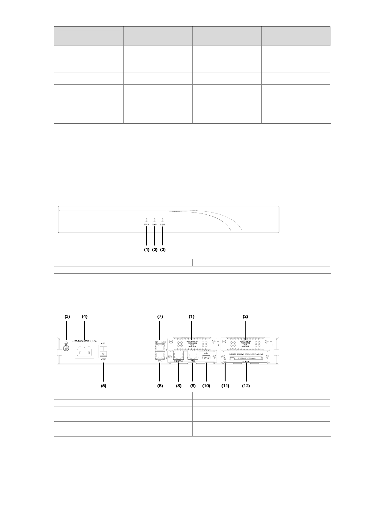
Figure 1-2 Rear view of MSR 20-20 router
(1) SIC slot2 (2) SIC slot1
(3) Grounding terminal (4) Power socket
(5) Power switch (6) Fixed Ethernet port0 (LAN0)
(7) Fixed Ethernet interface 1 (LAN1) (8) Console port (CON)
(9) Auxiliary port (AUX) (10) USB interface
(11) CF card LED (12) CF card interface
Panel LEDs
The following table gives the features of MSR 20-20 router LEDs:
1-3
Page 14
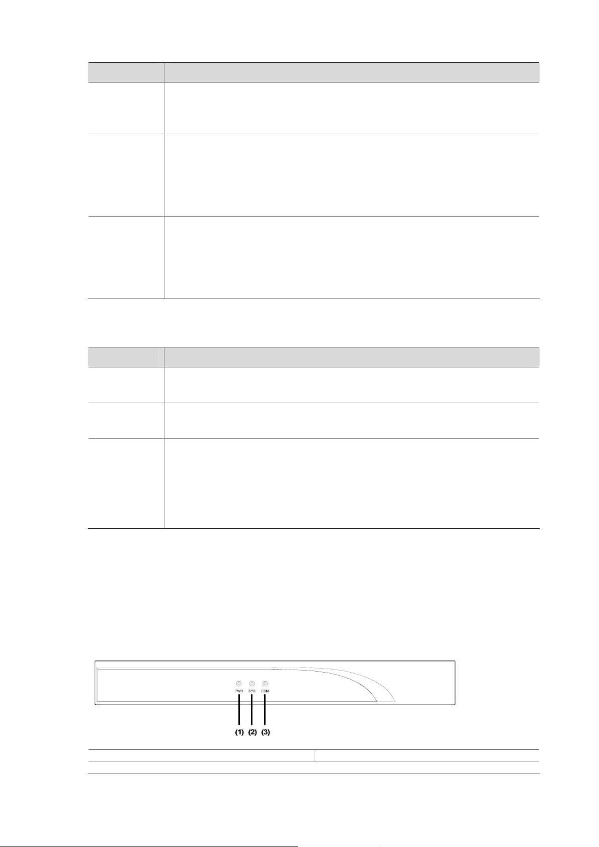
Table 1-5 Front panel LEDs description of MSR 20-20 router
LED Description
Power LED:
PWR
SYS
ESM
ON means power is on.
OFF means power is off.
System operating LED:
Green and fast blinking means the system is booting.
Green and slow blinking means the system is operating normally.
Yellow and fast blinking means the system is malfunctioning.
Steady OFF means the system does not operate normally.
ESM module LED:
Green and slow blinking means the system is booting.
Green means ESM card is operation normally.
Yellow means ESM card is malfunctioning.
Steady OFF means no ESM card is present.
Table 1-6 Rear panel LEDs of MSR 20-20 Router
LED Description
LINK
ACT
CF
MSR 20-21 Router
Appearance
1) Front view
OFF means no link is present.
ON means a link is present.
OFF means no data is being transmitted or received.
Blinking means data is being transmitted or received.
Steady green means a CF card is present.
Green and blinking means the CF card is reading/writing data. To prevent data
corruption, do not remove the running CF card.
Steady yellow means the present CF card is malfunctioning.
Steady OFF means no CF card is present or the present CF card cannot be
identified by the system.
Figure 1-3 Front view of MSR 20-21
(1) Power LED (PWR) (2) System LED (SYS)
(3) ESM LED (ESM)
1-4
Page 15
2) Rear view
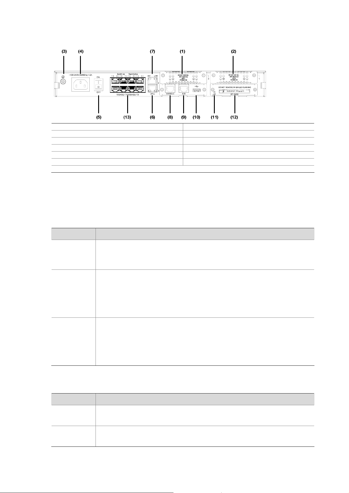
Figure 1-4 Rear view of MSR 20-21
(1) SIC slot2 (2) SIC slot1
(3) Grounding terminal (4) Power socket
(5) Power switch (6) Fixed Ethernet port0 (LAN0)
(7) Fixed Ethernet port1 (LAN1) (8) Console port (CON)
(9) Auxiliary port (AUX) (10) USB interface
(11) CF card LED (12) CF card interface
(13) Fixed L2 switching port (LAN2LAN9)
Panel LEDs
The following table gives the features of MSR 20-21 router LEDs:
Table 1-7 Front panel LEDs description of MSR 20-21 router
LED Description
Power LED:
PWR
ON means power is on.
OFF means power is off.
System operating LED:
Green and fast blinking means the system is booting.
SYS
Green and slow blinking means the system is operating normally.
Yellow and fast blinking means the system is malfunctioning.
Steady OFF means the system does not operate normally.
ESM module LED:
Green and slow blinking means the system is booting.
ESM
Steady green means ESM card is operation normally.
Steady yellow means ESM card is malfunctioning.
Steady OFF means no ESM card is present.
Table 1-8 The rear panel LEDs of MSR 20-21 Router
LED Description
LINK
ACT
OFF means no link is present.
ON means a link is present.
OFF means no data is being transmitted or received.
Blinking means data is being transmitted or received.
1-5
Page 16
LED Description
CF
MSR 20-40 Router
Appearance
1) Front view
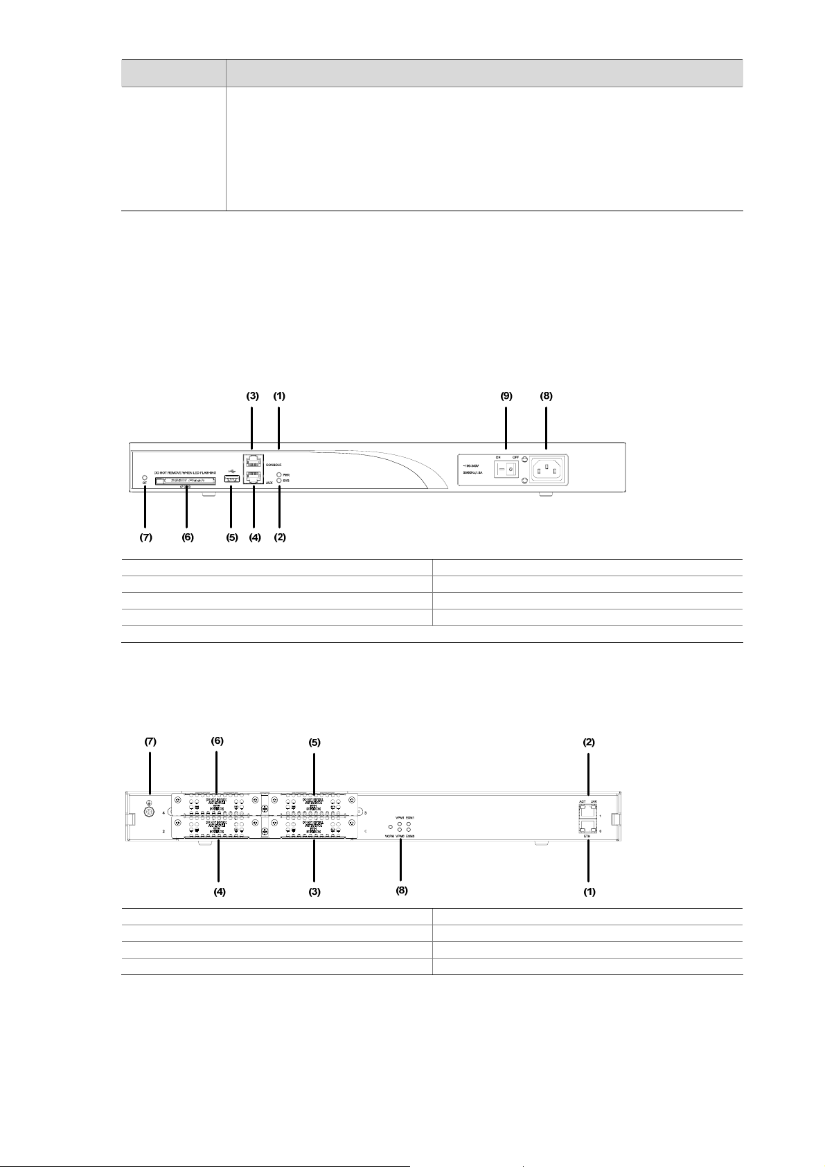
Figure 1-5 Front view of MSR 20-40
Steady green means a CF card is present.
Green and blinking means the CF card is reading/writing data. To prevent data
corruption, do not remove the running CF card.
Steady yellow means the present CF card is malfunctioning.
Steady OFF means no CF card is present or the present CF card cannot be
identified by the system.
(1) Power LED (POWER) (2) System LED (SYSTEM)
(3) Console port (CONSOLE) (4) Auxiliary port (AUX)
(5) USB interface (6) CF card
(7) CF card LED (8) Power socket
(9) Power switch
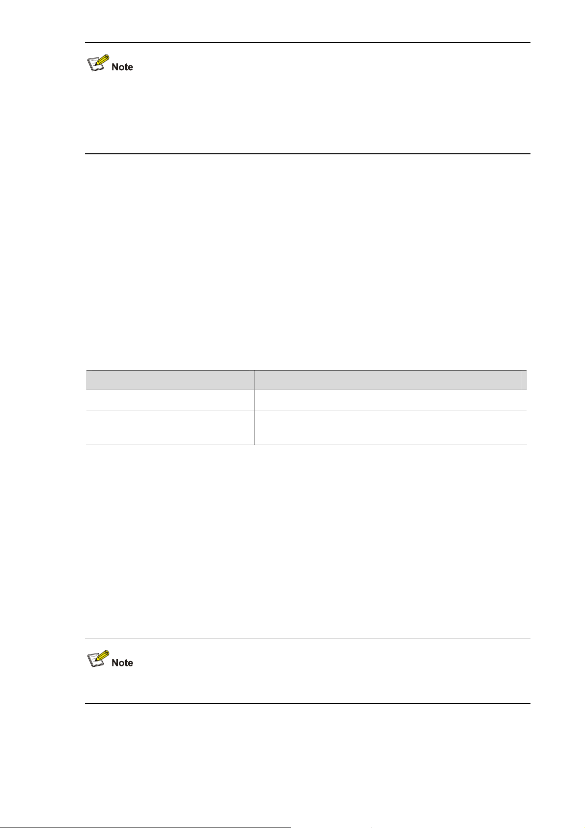
2) Rear view
Figure 1-6 Rear view of MSR 20-40
(1) FE interface 0 (2) FE interface 1
(3) SIC slot1 (4) SIC slot2
(5) SIC slot3 (6) SIC slot4
(7) Grounding terminal (8) LEDs
Panel LEDs
The description of LEDs on MSR 20-40 router is as follows:
1-6
Page 17

Table 1-9 Front panel LEDs description of MSR 20-40 router
LED Description
Power LED:
PWR
SYS
CF
Table 1-10 Rear panel LEDs description of MSR 20-40 router
ON means the circuit board supplies power normally.
OFF means the circuit board does not supply power.
Hardware system operation LED:
Blinking means the system is operating normally.
Steady ON or steady OFF means the system does not operate normally.
CF card LED:
Steady green means the CF card is in place, and can be identified by the router.
Blinking green means the CF card is being accessed and cannot be removed.
Steady yellow means the CF card is in place, but cannot be identified by the router.
OFF means no CF card is inserted or the CF card cannot be identified.
LED Description
LINK
ACT
ESM0 to 1
VCPM
VPM0 to 1
OFF means no link is present.
ON means a link is present.
OFF means no data is being transmitted or received.
Blinking means data is being transmitted or received.
OFF means no ESM is in the ESMx slot.
Steady green means an ESM is in the ESMx slot and operates normally.
Steady yellow means an ESM is in the ESMx slot but does not operate normally.
OFF means no VCPM is in the slot.
Steady green means a VCPM is in the slot and operates normally.
Steady yellow means a VCPM is in the slot but does not operate normally.
OFF means no VPM is in the VPMx slot.
Steady green means a VPM is in the VPMx slot and operates normally.
Steady yellow means a VPM is in the VPMx slot but does not operate normally.
Generic Modules
The MSR 20 series is available with generic modules such a s SIC interface card and ESM. For detailed
information about interface cards, refer to MSR Series Routers Interface Card and Interface Module
Manual.
SIC and DSIC Interface Cards
MSR series routers adopt modular design and support a wide range of optional SIC/DSIC interface
cards, providing various interfaces, such as synchronous/asynchronous serial interface, Ethernet
interface, E1/T1, ISDN BRI/PRI, ADSL, audio interfa c e, and Layer 2 switching interface, and so on.
1-7
Page 18
z For an MSR 20-40 router, 4FSW/1FEA/1GEC/1ADSL/1ADSL-I can only be installed in Slot 2 or
Slot 4.
z Currently, MSR 20 series routers do not support PoE and regard SIC-4FSW-POE and
DSIC-9FSW-POE (if used) as only ordinary Layer 2 switching modules.
ESM Module
z High-performance network data encryption ESM module (ESM-ANDE)
z Standard network data encryption ESM module (ESM-SNDE)
ESM module supports IPSec and by using hardware encryption expedites IP packet encryption. The
use of hardware encryption/decryption and hashing operation allows the router to encrypt p a ckets with
high performance and reliability.
The encryption card is optional. On a router installed with an encryption card, the main control board
functions to route IP packets and implement encryption-enabled VPN, while the encryption card
functions to encrypt packets.
Table 1-11 Encryption card attributes
Attribute Description
Protocol IPsec
Hardware encryption algorithm
VPM and VCPM Module
VPM (Voice Processing Module) functions to implement the encryption/decryption, EC and CNG of
voices.
VCPM (Voice Co-Processing Module) processes the voice data in combination with VPM.
z Voice co-processing module (RT-VCPM)
z 8-channel voice processing module (RT-VPM8)
z 16-channel voice processing module (RT-VPM16)
z 24-channel voice processing module (RT-VPM24)
z 32-channel voice processing module (RT-VPM32)
Key algorithms: DES, 3DES, AES
Authentication algorithms: HMAC-MD5-96, HMAC-SHA-1-96
VPM/VCPM is only available on MSR 20-40.
1-8
Page 19

Table of Contents
2 Installation Preparations···························································································································2-1
Requirements on Environment········································································································2-1
Requirements on Temperature/Humidity ························································································2-1
Requirements on Cleanness···········································································································2-1
Requirements on Electrostatic Discharge Prevention·····································································2-2
Requirements on Electromagnetic Environments···········································································2-2
Requirements on Preventing Lightning···························································································2-2
Checking the Rack ··························································································································2-3
Safety Precautions ··························································································································2-3
Installation Tools and Meters and Equipments···············································································2-3
i
Page 20

2 Installation Preparations
Requirements on Environment
MSR 20 Series must be used indoors. To ensure the normal operation and prolong their service life, the
following requirements for inst allation site must be met.
Requirements on Temperature/Humidity
To ensure the normal operation and prolong their service life, certain requirement s on temperat ure and
humidity in the equipment room shall be met. If the relative humidity is too high, the insulation m aterials
in it will deteriorate easily or even lead to electric leakage. Sometimes this will result in change to the
mechanical performance of the materials and rusting of the metal compon ents. If the relative humidity is
too low, the fastening screw will become loosen due to shrinkage of the isolation spacer. In an
environment with dry climate, static electricity may be produced, putting the CMOS of the route r to risk.
High temperature is of the greatest risk: for it will significantly degrade the router’s reliability, speed up
aging process of the insulating materials, and shorten the service life of the router.
The requirements on the temperature and humidity for MSR 20 Series are shown in the following table:
Table 2-1 Temperature/humidity requirements in the equipment room
Temperature Relative Humidity
0°C to 40°C (32°F to 104°F)
Requirements on Cleanness
Dust is harmful to the safe operation of the Router. Dust on the chassis may result in static ab so rption,
thus causing poor contact of the metal connection compon ents or points. Espe cially under the condition
of low indoor humidity, dust is easier to be absorbed.
The requirements on the dust concentration and diameter are shown in the following table:
Table 2-2 Limitation on dust content in equipment room
Diameter (μm)
Concentration
(particle/m³)
1.4 × 10⁷
5% to 90% (noncondensing)
0.5 1 3 5
7 × 10⁵
2.4 × 10⁵
1.3 × 10⁵
Besides the dust specifications, the equipment room of the Router should also meet the rigorous
requirements for the content of salt, acid and sulfide. These harmful gases could accelerate the metal
erosion and aging process of some part s. The specific limit s of these harmful g ases as SO
and CI2 are given in the following table.
NH
3
2-1
, H2S, NO2,
2
Page 21

Table 2-3 Harmful limits in equipment room
Gas Max (mg/m3)
SO2 0.2
H2S 0.006
NH3 0.05
CI2 0.01
Requirements on Electrostatic Discharge Prevention
Although many antistatic considerations have been given to MSR 20 Series, damage to the router’s
circuit or even the whole equipment may still happen when the static electricity exceeds the tolerance
threshold.
In the communication network to which the routers are connected, static induction mainly comes from
two aspects: external electric fields such as outdoor high voltage power line or thunder and internal
environment like flooring materials or the whole equipment structure. Thus, the following should be
considered to safeguard the equipment against ESD.
z Make sure that the equipment and the floor are well grounded.
z The equipment room is dust-proof.
z Maintain an appropriate humidity and temperature.
z Wear an ESD-preventive wrist strap and uniform when contacting the circuit board.
z Place the uninstalled circuit board on the antistatic workbench, with its face upward, or put it into
the static shielding bag.
z When observing or removing the uninstalled circuit board, please touch the edge of the circuit
board, and avoid contacting the devices on it.
Requirements on Electromagnetic Environments
The interference sources, no matter where they come from, af fect the routers with cap acitance couplin g,
inductance coupling, radiation of electromagnetic wave, common impedance (including the grounding
system) or conducting line (power line, signal line and transmission line etc.). So the following should be
considered:
z Take effective measures to prevent the power system from being interfered with by the power grid
system.
z Use an earthing system or lightning protection grounding different from that for the power supply
equipment and keep them as far as possible.
z Keep the router far away from the radio launcher, radar launcher, and high-frequency devices
working in high current.
z Use electromagnetic shielding when necessary.
Requirements on Preventing Lightning
Although many measures have been taken to protect MSR 20 Series from lightning, if the lightning
intensity exceeds a certain range, damage to the router may still happen. To protect the router from
lightning better, the following should be considered:
z Ensure the PGND wire of the chassis is well grounded.
2-2
Page 22
z Ensure the ground point of the socket of AC power supply is well grounded.
z To enhance the lightning protection capability of the power supply, a lightning arrester could be
installed at the input end of the power supply.
z As for the signal line outdoors to which the interface modules of MSR 20 series routers are
connected, such as ISDN line, telephone line, E1/T1 line, etc, a special lightning arrester should be
installed at the input end of the signal line to enhance the lightning protection capability.
Checking the Rack
When installing MSR 20 Series Routers, observe the following:
z There is spacing reserved at the air inlet and outlet in the router so as to facilitate the radiation of
the router cabinet.
z Make sure that the rack has a good ventilation system.
z Make sure that the rack is sturdy enough to support the weight of the device and the installation
accessories.
z Make sure that the rack is well-grounded.
Safety Precautions
Routers play a key role in data communications network. Please pay attention to the following:
It indicates that this operation is incorrect and may seriously damage the router or
endanger the operator . Please follow the correct operation procedures for sake of safety.
It indicates that during the installation and usage of the router, the operation needs
attention. If this operation is performed incorrectly, it might affect the operation of the router.
When installing or working on the router, you are recommended to:
z Keep the router far away from the heat sources and water/liquid.
z Make sure that the router has been correctly grounded.
z Wear an ESD-preventive wris t strap in installation and maintenance, making sure that the strap
has good skin contact.
z Do not hot swap the interface modules and interface cards of the router.
z Do not hot swap any cable.
z Correctly connect the interface cable for the router. Do not connect the telephone cable (including
the ISDN cable) to the AUX port or the console port.
z Use laser with caution. Do not directly stare into apertures or fiber-optic connectors that emit laser
radiation.
z Adopt uninterrupted power supply (UPS).
Installation Tools and Meters and Equipments
Tools
z Phillips screwdriver
z Straight screwdriver
z ESD-preventive twist strap
2-3
Page 23

Cables
z PGND wire and power cord
z Console cable
z Optional cables
Meters and equipment
z Hub or LAN switch
z Console terminal (it could be a PC)
z Equipment related to the selected modules
z Multimeter
MSR 20 series are not shipped with any installation tools, meters, or devices.
2-4
Page 24

Table of Contents
3 Installation··················································································································································3-1
Installation Process·································································································································3-1
Installing the Cabinet·······························································································································3-2
Installing the Router································································································································3-2
Installing the Router on a Workbench·····························································································3-2
Installing the Router on a Chassis···································································································3-2
Installing Generic Modules······················································································································3-3
Connecting the PGND Wire····················································································································3-4
Connecting the Power Cord····················································································································3-4
Power Input and PGND···················································································································3-5
Connecting the AC-input Power Cord·····························································································3-5
Connecting the Console Terminal···········································································································3-5
Fixed Interfaces·······································································································································3-6
Ethernet Interface····························································································································3-6
Ethernet Switching Interface ···········································································································3-8
Connecting AUX to a Modem··········································································································3-9
Interface Card Module···························································································································3-10
Installation and Uninstall of the Slide Rail on MSR 20-40 Router ························································3-10
Slide Rail ·······································································································································3-10
Installing the Slide Rail··················································································································3-10
Uninstalling the Slide Rail··············································································································3-11
Verifying Installation······························································································································3-11
i
Page 25
3 Installation
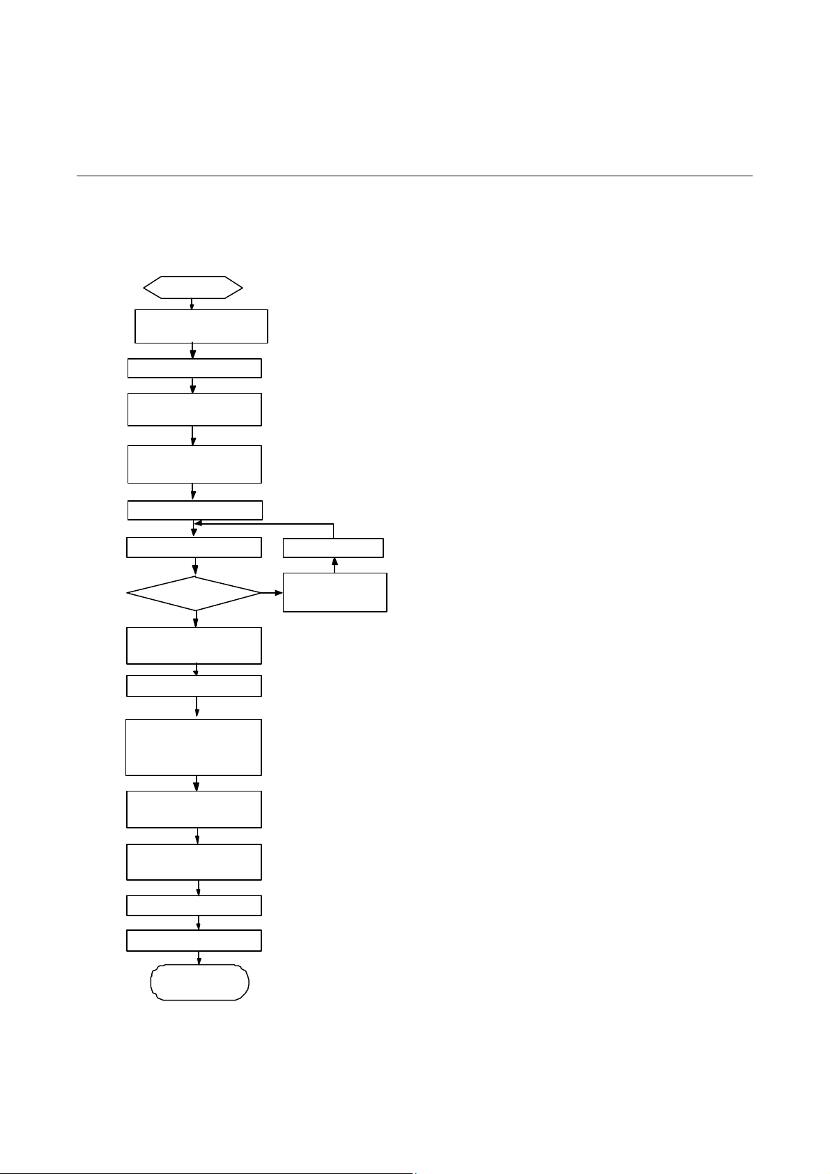
Installation Process
Figure 3-1 MSR 20 Series Router installation process
Start
Mount the rack
Connect PGND
C onnect the power
cord
Conn ect to the
console terminal
Verify installation
Pow er on
Normal?
YES
Turn o ff t he power
sw itch
Install the FICs
Install multifunctional
interface modules
Conn ect to the
Ethernet
NO
Troubleshoot
T u rn off th e
power switch
Connect to the WAN
Verif y installation
Pow er on
End
3-1
Page 26

Installing the Cabinet
For cabinet installation methods, refer to the part di scussing cabi net inst allation. S kip this section if you
want to mount your router on the tabletop or the rack of another vendor.
Installing the Router
Install the router after you have completed the installation preparations.
The installation of the router will be respectively described below according to the positions that it will be
placed:
z Installing the router on a workbench
z Installing the router on a chassis
Installing the Router on a Workbench
In many circumstances, you may not own a 19-inch st andard rack. Usually, the router will be installed on
a clean workbench. The operations are very simple, but still, you should be aware of the following items:
z Ensure the stability and well-grounding of the workbench.
z Leave a space of 10 cm (3.9 in.) around the router for heat dissipation.
z Do not place heavy objects on the router.
Installing the Router on a Chassis
Dimensions
MSR 20 Series Routers are designed for mounting in a 19-inch sta ndard ra ck and on the t ablet op. The
following table describes their dimensions:
Table 3-1 MSR 20-20/20-21/20-40 Router dimensions
Router model
MSR 20-20
MSR 20-21
MSR 20-40
Installation process
Step 1: Check the grounding and stability of the rack. Use the screws to fix the mounting ears at both
sides of the front panel or the rear panel of the router.
Dimensions
(H × W × D) (excluding feet and rack-mounting ear)
44.2 × 360 × 287.1 mm (1.74 × 14.17 × 11.3 in.)
44.2 × 360 × 287.1 mm (1.74 × 14.17 × 11.3 in.)
44.2 × 442 × 407.1 mm (1.74 × 17.4 × 16.02 in.)
Step 2: Put the router in a rack tray. For MSR 20-40 routers, use dedicated ears mounted on the rear
panel if no tray is available. Depending on the actual situation, slide the router along the chassis guide s
to an appropriate place.
Step 3: Fasten the mounting ears with the recess screws to fix the router in the rack horizontally and
firmly. The specifications of recess screws should satisfy the installation requirements and the surface
of the screws should be anti-rust.
3-2
Page 27

Figure 3-2 Installing MSR 20 Series Router in a rack
(1) Mounting ear (2) Guide
Figure 3-3 Installing ears on the rear panel of the MSR 20-40 Series Router
Installing Generic Modules
Installing generic modules includes installing the memory, ESM cards, and FICs. For more information
about the memory and ESM cards and their installation, refer to Chapter 6 “Hardware Maintenance” in
this manual. For more information about FICs and their installation, refer to MSR 20/30/50 Series
Routers Interface Card and Interface Module Manual.
3-3
Page 28
Connecting the PGND Wire
The normal connection of the protection ground (PGND) on the router chassis is an essential safegua rd
against the lightning shocks and interference. You must correctly connect the PGND when installing o r
using the router.
The power input end of MSR 20 Series router is connected to a noise filter. The neutral point of the
noise filter is directly connected to the chassis and is called protection ground (PGND). The PGND wi re
must be well grounded, so as to safely conduct the faradism and leaky electricity to the earth ground,
and thereby improve the capability of the whole device to guard against the electromagnetic
interference. This PGND wire can also protect the router against the lightning caused by the connection
with the external network lines, such as E1/T1 line, ISDN/PSTN line.
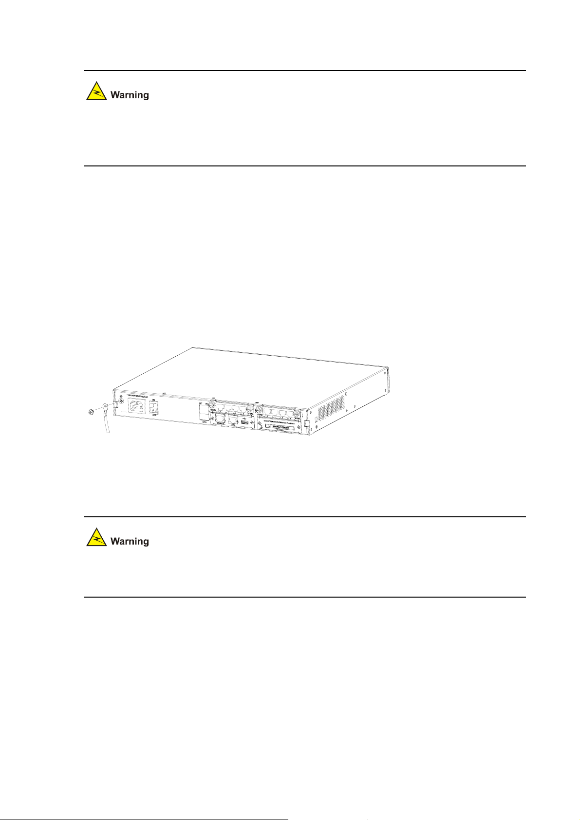
The grounding screw of MSR 20 Series Router, which is marked with grounding label, is located near
the AC power socket and its switch on the rear panel of the chassis, as shown in the following figure:
Figure 3-4 Grounding terminal of the router
Use a PGND wire to connect the screw to the earth ground, and the grounding resistance shou ld not be
greater than 5-ohm. Likewise, if the router is installed in a 19-inch st andard rack, this ra ck is required to
be grounded too.
When the router is in normal operation, it is required to be well gro unded. Otherwise, the rout er cann ot
reliably avoid lightning, which may damage the router itself and even the peer device.
Connecting the Power Cord
The MSR 20-20/20-21/20-40 router is available with AC-powered units.
3-4
Page 29

Power Input and PGND
Table 3-2 Power input and PGND of the MSR 20-20/20-21/20-40 router
Item Description
Power input
PGND
Connecting the AC-input Power Cord
AC power supply
Rated voltage range: 100 VAC to 240 VAC, 50 Hz/60 Hz
The following figure illustrates the partial external appearance of the power socket for an AC-powered
router:
Figure 3-5 Power socket on AC-powered units
(1)(2)
(1) Power switch (2) AC input
100 VAC to 240 VAC power input socket
Connected to the earth ground with ground cable
AC power socket (recommended)
You are recommended to use a three-terminal single-phase power socket with ground contact, which
must be grounded reliably. Normally, the ground contact of the power supply system in a building was
buried during construction and cabling. Still, before connecting the AC-input power cord, you must
make sure that the power supply of the building is well grounded.
Connecting the AC-input power cord
Step 1: Make sure that the PGND is securely conn ected to the earth ground.
Step 2: When the power switch of the router is in the OFF position, insert one end of the power cord
accompanying the router into the power socket on the chassis rear pan el, and connect the other end of
the cable to an AC po wer source at your installation site.
Step 3: Place the power switch of the router to the ON position.
Step 4: Check that the PWR LED on the front panel of the router is on for correct connection.
Connecting the Console Terminal
Console port
MSR 20 series provides an RS232 asynchronous serial console (CON) port for router configuration,
through which you can complete the configuration of the router. For its attributes, refer to
3-5
Table 3-3:
Page 30

Table 3-3 Attributes of the console port
Attribute Description
Connector
Interface standard
Baud rate
Function
RJ-45
RS232
9600 bps (default) to 115,200 bps
Connecting to the ASCII terminal
Connecting to the serial interface of the local PC and running
terminal emulation program on the PC
Command line interface
Console cable
Console cable is an eight-wire shielded cable. At one end of the cable is a crimped RJ-45 connector to
the console port on the router; at the other end of the cable is a DB-9 (female) connector to the serial
port on the console terminal.
The following figure illustrates the console cable.
Figure 3-6 Console cable
Connecting the console cable
Follow these steps to connect the router to a console terminal:
Step 1: Select a console terminal.
It can be a standard ASCII terminal with an RS232 serial port, or more commonly, a PC.
Step 2: Connect the console cable.
Power down the router and the console terminal, conn ect the RS232 serial port o n the console terminal
to the console port on the router through the console cable.
Verify the connectio n and powe r up the devices. The console terminal sho ws the st artup inform ation of
the router if the connection is correct.
Fixed Interfaces
Ethernet Interface
Ethernet interface
MSR 20 Series Routers are available with fixed 100Base-TX FE interface(s) and Ethernet
modules/cards for expansion. For more information, refer to MSR 20/30/50 Series Routers Interface
Card and Interface Module Manual. The following table describes Ethernet interface attributes.
3-6
Page 31

Table 3-4 Attributes of the Ethernet interface
Attribute Description
Connector
Interface
Frame format
Operating mode
RJ-45
MDI/MDIX auto-sensing
Ethernet_II
Ethernet_SNAP
10/100 Mbps auto-sensing
Full duplex/half duplex
MDI (Media Dependent Interface) is a typical type of Ethernet interface provided by network adapters.
MDIX is crossover media-dependent interface, which is commonly found on a Hub or LAN switch.
Ethernet cable
Ethernet interfaces usually use category 5 twisted pair cables, as shown in the following figure:
Figure 3-7 Ethernet cable
Ethernet cables fit into the following two categories:
z Standard cable, also called straight-through cable, at both ends of which, wires are crimped in the
RJ-45 connectors in the same sequence. The cable conne cts different cate gories of devices, such
as a terminal device (PC for example) or router to a Hub or LAN switch. The cable accompanying
the router is standard cable.
z Crossover cable, at both ends of which, wires are crimped in the RJ-45 connectors in different
sequences. The cable connects the same category of devices, such as PC to PC or PC to router.
You can make crossover cables yourself as needed.
In making network cables, shielded cables are preferred for electromagnetic compatibility sake.
Connecting the Ethernet cable
Follow the steps below to connect an Ethernet cable:
Step 1: Connect one end of the Ethernet cable to an Ethernet port on the router and the other end to
another device.
3-7
Page 32

z For a 10/100 Mbps port provided by the RPU, connect it to a PC or another router using a
crossover cable or to a Hub or LAN switch using a straight-through cable.
Step 2: V iew the LINK LED of the Ethernet interface: ON means a l ink is present. OFF means no lin k is
present; check the line for the cause.
Ethernet Switching Interface
The MSR 20-21 Router is available with fixed 100Base-TX FE interface(s). The following table
describes Ethernet switching interface attributes:
Table 3-5 Attributes of the Ethernet switching interface
Attribute Description
Connector
Interface
Frame format
Operating mode
RJ-45
MDI/MDIX
Ethernet_II
Ethernet_SNAP
10/100 Mbps auto-sensing
Full duplex/half duplex
MDI (media dependent interface is a typical type of Ethernet interface provided by network adapters.
MDIX is crossover media-dependent interface, which is commonly found on a Hub or LAN switch.
Ethernet cable
Ethernet interfaces usually use category 5 twisted pair cables, as shown in the following figure:
Figure 3-8 Ethernet cable
Ethernet cables fit into the following two categories:
z Standard cable, also called straight-through cable, at both ends of which, wires are crimped in the
RJ-45 connectors in the same sequence. The cable conne cts different cate gories of devices, such
as a terminal device (PC for example) or router to a Hub or LAN switch. The cable accompanying
the router is straight-through cable.
3-8
Page 33

z Crossover cable, at both ends of which, wires are crimped in the RJ-45 connectors in different
sequences. The cable connects the same category of devices, such as PC to PC or PC to router.
You can make crossover cables yourself as needed.
In making network cables, shielded cables are preferred for electromagnetic compatibility sake.
Connecting the Ethernet cable
Follow the steps below to connect an Ethernet cable:
Step 1: Connect one end of the Ethernet cable to an Ethernet port on the router and the other end to
another device.
z For a 10/100 Mbps port provided by the RPU, connect it to a PC or another router using a
crossover cable or to a Hub or LAN switch using a straight-through cable.
Step 2: View the LINK LED of the Ethernet interface: ON means a link is present.
Connecting AUX to a Modem
AUX port
AUX is an RS232 asynchronous serial interface, which can back up a WAN interface and provide dial
connection. In case of console failure, AUX can function as a console interface.
AUX cable
AUX cable is an eight-wire shielded cable. At one end of the cable is an RJ-45 connector for connecting
the console port on the router . At the other end are DB-9 (male) con nector and DB-25 (male) connector.
You can plug either of them into the serial port on a modem as needed.
Figure 3-9 AUX cable
Connecting the AUX cable
Follow these steps to connect the AUX cable.
Step 1: Plug the RJ-45 connector of the cable into the AUX port on the main bo ard.
Step 2: Plug the DB-25 or DB-9 connector into the serial port on the analog modem.
3-9
Page 34

When using the AUX interface for remote configuration or dial backup, you need to connect the local
modem to the remote modem through PSTN and then to the remote device. For the configuration
procedures, refer to MSR 20/30/50 Series Routers User Manual.
Interface Card Module
The MSR 20 Series Routers are available with various types of interface card modules. For detailed
information refer to MSR 20/30/50 Series Routers Interface Card and Interface Module Manual.
Installation and Uninstall of the Slide Rail on MSR 20-40 Router
Slide Rail
SIC slide rail
Figure 3-10 SIC slide rail
Installing the Slide Rail
Figure 3-11 Install the slide rail
Figure 3-12 Fix the slide rail
3-10
Page 35

Uninstalling the Slide Rail
Figure 3-13 Loosen the screw
Figure 3-14 Draw out the slide rail
Verifying Installation
During router installation, you must verify installation each time you power on the router, making sure
that:
z Whether there is enough space around the router for heat-dissipation, and whether the workbench
is stable enough.
z Whether the power supply that the power cord connects to is compliant with that required by the
router.
z Whether the PGND wire of the router is correctly connected.
z Whether the router is correctly connected to other devices, such as the console terminal.
The check after installation is very important. The stability, grounding of the router and powe r supply will
directly affect the operation of the router.
3-11
Page 36

Table of Contents
4 Startup and Configuration························································································································4-1
Startup·····················································································································································4-1
Setting up Configuration Environment·····························································································4-1
Powering on the Router···················································································································4-3
Startup Process·······························································································································4-4
Configuration Fundamentals···················································································································4-5
Basic Configuration Procedures······································································································4-6
Command Line Interface·················································································································4-6
Arranging Slots and Numbering Interfaces ·····················································································4-7
i
Page 37

4 Startup and Configuration
Startup
You can only configure the MSR 20 router through the console port if it is the first time you use it.
Setting up Configuration Environment
Connecting the router to a console terminal
To set up the local configuration environment, RJ-45 connector of the console cable needs to be
connected to the console port on the router, and DB-9 connector to the serial interface of a PC, as
shown in the following figure.
Figure 4-1 Local configuration through Console port
Devece
Console cable
Setting the parameters for console terminal
1) Opening the console terminal and setting up a new connection. Select the serial interface to be
connected in the Connect using field in the [Connect to] box as shown in the following figure. Note
that the selected serial interface should be consistent with the actual serial interface co nne cte d by
the console cable.
PC
4-1
Page 38

Figure 4-2 Setting the connection port in the local configuration
2) Setting terminal parameters. As shown in the following figure, in the properties dialog box of the
serial interface, set the baud rate to 9600, data bit to 8, no parity check, stop bit to 1, and flow
control to none. Then, click <OK> to return to the HyperTerminal window.
Figure 4-3 Setting serial interface parameters
3) Set HyperTerminal properties. Select [File\Properties\Settings] in the HyperTerminal to enter the
properties setting window as shown in the following figure. Select th e terminal emulation type to be
VT100 or auto detect, and click <OK> to return to the HyperTerminal window.
4-2
Page 39

Figure 4-4 Setting terminal type
Powering on the Router
Checking before power-on
Check according to the following items before powering on the router.
z Whether the power cord and PGND wire are correctly connected.
z Whether the voltage of the power supply complies with the requirement of the router.
z Whether the console cable is correctly connected, whether the PC or terminal for configuration is
open, and whether the settings are done.
z Whether the CF card is loosed.
Before powering on the router, the user should be aware where the switch of the power supply to the
router is located, so that the power supply can be disconnected in time once accidents oc cur.
Powering on the router
z Turn on the site power.
z Turn on the power switch on the router.
Checking/operating after power-on
After powering on the router, check that:
1) The LEDs on the front panel show that the router is operating normally.
2) The console terminal displays normally.
4-3
Page 40

For local configuration, after you power on the router, you can see the startup banner. See section
Startup Process”.
“
3) After completing the power-on self-test (POST), the system asks you to press <Enter>. When the
prompt appears, you may proceed to configure the router.
Startup Process
During the power-on or reboot process, the console terminal displays the following information first:
Do you want to go on checking sdram? Yes or not(Y/N)
If you enter <N> or wait for two seconds, the system runs the Boot ROM program and the following
banner appears on the console screen:
system start booting......Version 2.11
Press CTRL+D to stop auto-boot
Press <Ctrl+D> and the system will enter the basic BootROM menu. Otherwise, the system will enter
the program decompression process of the extended BootROM segment.
The system enters the basic BootROM menu only if <Ctrl+D> is pressed immediately (within 3 seconds)
after the statement “Press CTRL+D to stop auto-boot” appears; otherwise, the system will enter the
extended BootROM decompression process.
Booting Normal Extended BootRom
Decompressing...done!
Ensure the baudrate is set to 9600bps! Starting at 0xa00000...
*******************************************************
* *
* MSR20-21 BOOTROM, Version 2.11 *
* *
*******************************************************
Copyright(c) 2004-2007
Compiled date: Apr 09 2007, 08:52:28
CPU type : MPC8248
CPU L1 Cache : 16KB
CPU Clock Speed : 400MHz
Memory Type : SDRAM
Memory Size : 256MB
Memory Speed : 100MHz
BootRom Size : 4096KB
CPLD Version is 2.00
HardWare Version is 3.00
4-4
Page 41

CF Card is Inserted, now is mounting...
cf:/ - Volume is OK
Mount CF Card OK!
CF Card Size:256MBytes
Press Ctrl+B to enter extended boot menu...
Enter <Ctrl+B>, the system will enter the extended BootROM menu; otherwise, the system will enter the
program decompression process.
The system enters the Boot extended menu only if <Ctrl+B> is pressed immediately (within six seconds)
after the statement “Press Ctrl+B to enter extended Boot Menu...” appears. Otherwise, you will enter
the program decompression process. To re-enter the Boot extended menu during the decompression
process, you need to reboot the router.
The current starting file is main application file--cf:/main.bin!
The main application file is self-decompressing...
Decompressing...done!
System is starting.....
Ensure the baudrate is set to 9600bps!
Starting at 0x10000...
usrRoot() end
leave BSP
id=0x2000,proc=0xd75bd0
DRV_Time_GetTimeZone return 1
DRV_Time_SetTimeZone return 1
id=0x70000,proc=0xd96bfc...
......
......
......
User interface con0 is available.
Press ENTER or ACTIVATION KEY to get started.
Press <Enter> and the screen will display:
<DEVICE>
This prompt indicates that the router has entered the user view, and now the router can be configured.
Configuration Fundamentals
In general, the configuration steps are as follows:
4-5
Page 42

Step 1: Before configuring the router, the networking requirements should be made specific, which
include networking purpose, the role of the router in the network, the division of subnets, WAN type and
transmission medium, the network security policy and reliability.
Step 2: Based on the above requirements, draw a clear and integrated networking diagram.
Step 3: Configure the WAN interface of the router. First, configure the physical operating parameters
(e.g., the operating mode of the serial interface, baud rate and synchronous clock) of the interface
according to the transmission medium of the WAN. For the dial-up interface, the user also needs to
configure DCC parameters. Then, configure the link layer protocol encapsulated on the interface and
the related operating parameters according to the WAN type.
Step 4: Configure the IP addresses or IPX network n umbers of all the interfaces on the router according
to the division of the subnets.
Step 5: Configure the routes. If it is necessary to enable a dynamic routing protocol, the user should
configure the related operating parameters of the protocol.
Step 6: If special security is required, perform the security config ur ation for the router.
Step 6: If special reliability is required, perform the reliability configuration for the router.
See MSR 20/30/50 Series Routers User Manual for the configuration details of the protocols or
functions of the router.
Basic Configuration Procedures
Command Line Interface
Characteristics of the command line interface
The command line interface of MSR 20 Series Routers provide s a number of configuration commands,
which can be used to configure and manage the router. The command line interface has the following
characteristics:
z Performs the local configuration through Console port
z Performs the local or remote configuration through telnet command, which can be used to directly
log on and manage other routers.
z Users can enter “?” anytime to get online help.
z Provides network diagnostic tools, such as Tracert and Ping, to quickly diagnose the availability of
the network.
z Provides all kinds of detailed debugging information to diagnose network faults.
z The command line interpreter adopts fuzzy search for the keywords of the command. If the user
enters the conflict-free keyword for a command, the command will be interpreted accordingly. For
example, for a display command, the user can just enter dis.
Command line interface
The command line interface of MSR 20 Series routers provides plenty of configuration commands. All
the commands are grouped in system view . Each group corre sponds to a view. The user can use these
commands to switch between different configuration views. In general, only certain commands can be
executed under a particular view. But some common commands (such as ping and display
current-configuration) can be executed in all views.
4-6
Page 43

Arranging Slots and Numbering Interfaces
Slot arrangement
The MSR 20 series provides many types of interfaces, such as console, AUX, Ethernet, serial
(synchronous/asynchronous), and asynchronous port. The following describes how these interfaces
are numbered.
Figure 4-5 Slot arrangement on the MSR 20-20
(2)(3)
(1)
(1) Slot0 (2) Slot1 (3) Slot2
Figure 4-6 Slot arrangement on the MSR 20-21
(2)(3)
(1)
(1) Slot0 (2) Slot1 (3) Slot2
Figure 4-7 Slot arrangement on the MSR 20-40
(4)(5)
(1)(2)(3)
(1) Slot0 (2) Slot1 (3) Slot2
(4) Slot3 (5) Slot4
Interface numbering
The MSR 20 Series Router interface adopts “two dimension” numbering rules, sh own in the following:
4-7
Page 44

z The interfaces are represented by interface-type X/Y, where interface-type can be serial,
asynchronous, or Ethernet, and so on; X specifies the slot number; Y specifies the interface
number.
z Different interfaces on an interface module share the same slot number X.
z For every interface, Y starts from 0 and Y indicates the interface sequence on the interface module,
from left to right.
If you install an SIC-1FEA and an SIC-4FSW respectively in SLOT1 and SLOT2 on the AR MSR 20-20,
the Ethernet interfaces are numbered as follows:
z Fixed Ethernet interfaces are Ethernet 0/0 and Ethernet 0/1;
z The Ethernet interface on the SIC-1FE is Ethernet 1/0;
z The Ethernet interfaces on the SIC-4FSW module are Ethernet 2/0, Ethernet 2/1, Ethernet 2/2 and
Ethernet 2/3.
4-8
Page 45

Table of Contents
5 Software Maintenance·······························································································································5-1
Introduction ·············································································································································5-1
Files·················································································································································5-1
Software Maintenance Methods······································································································5-3
BootROM Menu ······································································································································5-4
Main BootROM Menu······················································································································5-4
BootROM Submenus·······················································································································5-6
Upgrading BootROM Through Serial Port ······························································································5-9
Modifying Serial Port Parameters····································································································5-9
Upgrading BootROM·····················································································································5-11
Upgrading Application Program Through Serial Port············································································5-12
Upgrading Application Program Through Ethernet Interface································································5-12
Configuring Ethernet Parameters··································································································5-12
Upgrading Application Program Through Ethernet Interface························································5-14
Maintaining Application Program and Configuration Through Command Lines···································5-16
Maintaining the Router with TFTP Server·····················································································5-16
Maintaining the Router with FTP Server ·······················································································5-18
Maintaining Application Program and Configuration File······································································5-21
Dealing with Router Password Loss·····································································································5-24
User Password Loss······················································································································5-24
BootROM Password Loss ·············································································································5-25
Super Password Loss····················································································································5-25
Backing up and Restoring BootROM····································································································5-25
i
Page 46

5 Software Maintenance
Introduction
Files
BootROM program file
The file is used for booting application at boot. A complete BootROM file includes two segments: basic
and extended.
Application program file
The router is available with Dual Image function. By default, the system defines and attempts to boot in
order with three boot files: main, backup, and secure, provided they are available with CF card. If the
router fails to boot with the secure boot file, it prompts the boot failure. For more information about the
boot files, refer to section “
Maintaining Application Program and Configuration File”.
The following table gives default names and types of boot files.
Table 5-1 Default names and types of the boot files
Boot file File name File type
Main boot file main.bin M
Backup boot file backup.bin B
Secure boot file secure.bin S
z The application programs for system boot can be type M, B and S, but not type N. You can store
them in Flash memory, but only one for each. For example, if an M+B file exists, it is impossible to
have another M or B file. If you change the file type of another file to B, the M+B file becomes a type
M file.
z You can modify the file name of an application file in CF card using the command after it boots. You
cannot modify the file type of a type S application image file, but you can modify the file type of type
M/B and N application program files in the BootROM menu or using commands after the
application program boots.
z Secure boot file is the last resort for system boot. You can download it in the BootROM menu and
must name it secure.bin. However, you cannot modify this file or change the type of another file to
S. If you change the name of the secure boot file with the rename command after the system bo ots,
the file is removed from CF card. To use the secure boot file after that, you need to download it
again.
5-1
Page 47

Configuration file
The file stores configuration information of the router.
By default, the system defines and attempts to boot in order with three configuration files: main, backup,
and default, provided they are available with CF card. If the router fails to boot with the secure boot file,
it prompts the boot failure. For more information about the boot files, refer to section “
Application Program and Configuration File”.
The following table describes the three configuration files.
Table 5-2 Description on the three configuration files
Configuration file File type Description
Main configuration file M Used by the system for booting by default.
Maintaining
Backup configuration file B
Used by the system for booting when it fails to boot
with the main configuration file.
Used by the system for booting when it fails to boot
with the backup configuration file. If the system fails to
boot with the default configuration file, it boots with
Default configuration file M/B/N
null configuration. The name of the default
configuration file has something to do with the router
brand. The main and backup configuration operations
on the default configuration file is the same with
common configuration files.
z The configuration files for system boot can be type M, B and default configuration file of type N, but
not non-default configuration file of type N (i.e. neither M nor B).
z You can modify the file name of a configuration file in CF card using the command after it boots.
You cannot modify the type of the default configuration file, but you can modify the file type of type
M/B and N configuration files in the BootROM menu or using commands after the application
program boots.
You can store them in Flash memory, but only one for each. For example, if an M+B file exists, it is
impossible to have another M or B file. If you change the file type of another file to B, the M+B file
becomes a type M file.
5-2
Page 48

z The file name cannot be longer than 64 characters (including drive letter and a string terminator. If
the drive letter is “CF: /”, the file name can be at most [ 64-1-4 ] = 59 characters in length; or, errors
will occur in file operation. Typically, the file name is recommended to be not more than 16
characters.
z The extension ASCII characters (ASCII>=128) and invisible characters (ASCII<33) cannot be
included in the file name.
z The following characters cannot be included in the file name: ”, ‘, ?, \, space, *, |, <, /, :, >, ~.
z The character “.” can be included in the file name, but cannot be the first or last character of the file
name. Two consecutive “.”s are not allowed.
Software Maintenance Methods
z Upgrading BootROM and application program using XModem protocol through serial port.
z Upgrading application program from TFTP/FTP server through Ethernet interface in BootROM.
z Uploading/downloading application program and configuration file from TFTP/FTP server via
command lines.
z BootROM program is upgraded through binding with the Comware version. You do not need to
upgrade it separately. The system automatically upgrades BootROM to be the latest version while
upgrading Comware.
z Check the current version of BootROM and application program before upgrading. For the
association between Comware version and BootROM program, see the corresponding Release
Notes.
5-3
Page 49

Figure 5-1 Upgrade BootROM and Comware under Comware V5 enviro nment
Start
Com ware ve rs i on
Upgrade Comware ?
Y
Choose correct Comware
Choo s e upgrade m ode
Via network
interface
Xmodem
upgrade
TFTP
upgrade
Upgrade
End
N
FTP
upgrade
BootROM Menu
Main BootROM Menu
When the router is powered on and reboots, the console terminal displays:
Do you want to go on checking sdram? Yes or not(Y/N)
This prompts whether to perform memory check. Press <N/n> button to ignore it.
z The memory check function is developed for test. Since the test takes long time, this function is
often not used.
z Generally, to check 128 MB memory needs 16 seconds. The time of checking other memories is
calculated accordingly.
z When the prompt is displayed, press <Y/y> button within two seconds to start ch ecking. If normal, it
displays:
SDRAM Check OK!
z If you do not press the button within two seconds, it is defaulted to select <N/n>, and the memory
check is not enabled.
Proceed to boot, and the system prompts:
5-4
Page 50

system start booting......Version 2.11
Press CTRL+D to stop auto-boot
Booting Normal Extended BootRom
Decompressing...done!
Ensure the baudrate is set to 9600bps!Starting at 0xa00000...
*******************************************************
* *
* MSR20-21 BOOTROM, Version 2.11 *
* *
*******************************************************
Copyright(c) 2004-2007
Compiled date: Apr 09 2007, 08:52:28
CPU type : MPC8248
CPU L1 Cache : 16KB
CPU Clock Speed : 400MHz
Memory Type : SDRAM
Memory Size : 256MB
Memory Speed : 100MHz
BootRom Size : 4096KB
CPLD Version is 2.00
HardWare Version is 3.00
CF Card is Inserted, now is mounting...
cf:/ - Volume is OK
Mount CF Card OK!
CF Card Size:256MBytes
Press Ctrl+B to enter extended boot menu...
The extended BootROM menu is referred to as main BootROM menu hereafter in this manual except
for special statement.
Press <Ctrl+B> when it displays “Press Ctrl+B to enter extended boot menu...”. Then, the system
prompts:
Please input Boot ROM password:
You have three chances to provide the correct BootROM password (the initial setting is void). If you fail
to do that, you need to reboot the system. After you enter the correct password, the console screen
displays.
==================<EXTENDED-BOOTROM MENU>====================
5-5
Page 51

| <1> Boot From CF Card |
| <2> Enter Serial SubMenu |
| <3> Enter Ethernet SubMenu |
| <4> File Control |
| <5> Modify Bootrom Password |
| <6> Ignore System Configuration |
| <7> Boot Rom Operation Menu |
| <8> Clear Super Password |
| <9> Device Operation |
| <a> Reboot |
=============================================================
Enter your choice(1-a):
The menu is defined as follows:
Table 5-3 Main BootROM menu
Menu item Description
<1> Boot From CF Card Boot from the CF card.
<2> Enter Serial SubMenu
<3> Enter Ethernet SubMenu
<4> File Control
<5> Modify Bootrom Password Modify BootROM password.
<6> Ignore System Configuration Ignore system configuration.
<7> Boot Rom Operation Menu
<8> Clear Super Password Delete super password.
<9> Device Operation
<a> Reboot Reboot the router.
BootROM Submenus
Enter serial submenu. Refer to section “
Enter serial submenu”
or details.
Enter Ethernet submenu. Refer to section “
Enter Ethernet
interface submenu” for details.
File control submenu. Refer to “
File control submenu” for
details.
BootROM operation submenu. Refer to section “
BootROM
operation submenu” for details.
Device Operation menu, which is used to select memory
device.
Enter serial submenu
This submenu can be used for upgrading application program, changing serial baud rate, and other
operations.
Enter <2> under the main BootROM menu to enter the serial submenu:
======================<SERIAL SUB-MENU>======================
|Note:the operating device is CF Card |
| <1> Download Application Program To SDRAM And Run |
| <2> Update Main Application File |
| <3> Update Backup Application File |
| <4> Update Secure Application File |
5-6
Page 52

| <5> Modify Serial Interface Parameter |
| <6> Exit To Main Menu |
=============================================================
Enter your choice(1-6):
The menu is defined as follows:
Table 5-4 BootROM serial submenu
Menu item Description
<1> Download Application Program To SDRAM
And Run
Download the application program to SDRAM
and run it.
<2> Update Main Application File Upgrade the main application file.
<3> Update Backup Application File Upgrade the backup application file.
<4> Update Secure Application File Upgrade the secure application file.
<5> Modify Serial Interface Parameter Modify serial interface parameter.
<6> Exit To Main Menu Exit to the main menu.
Enter Ethernet interface submenu
Enter <3> in BootROM menu to enter the Ethernet interface submenu. The system displays:
====================<ETHERNET SUB-MENU>======================
|Note:the operating device is CF Card |
| <1> Download Application Program To SDRAM And Run |
| <2> Update Main Application File |
| <3> Update Backup Application File |
| <4> Update Secure Application File |
| <5> Change Ethernet Parameter |
| <6> Exit To Main Menu |
| < Ensure The Parameter Be Modified Before Downloading! > |
=============================================================
Enter your choice(1-6):
The menu is defined as follows:
Table 5-5 Enter Ethernet interface submenu
Menu item Description
<1> Download Application Program To SDRAM
And Run
Download application program to SDRAM and
run it.
<2> Update Main Application File Upgrade the main application file.
<3> Update Backup Application File Upgrade the backup application file.
<4> Update Secure Application File Upgrade the secure application file.
<5> Change Ethernet Parameter Modify Ethernet parameters.
<6> Exit To Main Menu Exit to the main menu.
5-7
Page 53

File control submenu
Enter <4> under the main BootROM menu to enter the file control submenu. Through this submenu, the
system can display application program file type in memory, modify file name and delete files. The
prompt is shown below:
========================<File CONTROL>=======================
|Note:the operating device is CF Card |
| <1> Display All File |
| <2> Set Application File type |
| <3> Set Configuration File type |
| <4> Delete File |
| <5> Exit To Main Menu |
=============================================================
Enter your choice(1-5):
The submenu is defined as follows:
Table 5-6 File control submenu
Menu item Description
<1> Display All File Display all files.
<2> Set Application File type Set application file type.
<3> Set Configuration File type Set configuration file type.
<4> Delete File Delete files.
<5> Exit To Main Menu Exit to the main BootROM menu.
BootROM operation submenu
Enter <7> under the main BootROM menu to enter the BootROM operation menu:
=====================<BOOT ROM OPERATION>====================
|Note:the operating device is CF Card |
| <1> Backup Full Boot ROM |
| <2> Restore Full Boot ROM |
| <3> Update Full Boot ROM With XModem |
| <4> Update Extended Boot ROM With XModem |
| <5> Update Basic Boot ROM With XModem |
| <6> Exit To Main Menu |
| Note:When Update Full/Extended/Basic BootRom,they are the |
| same file |
=============================================================
Enter your choice(1-6):
The submenu is defined as follows:
5-8
Page 54

Table 5-7 BootROM operation submenu
Menu item Description
<1> Backup Full Boot ROM Backup full BootROM.
<2> Restore Full Boot ROM Restore full BootROM.
<3> Update Full Boot ROM With XModem Upgrade full BootROM through XModem.
<4> Update Extended Boot ROM With XModem Update extended BootROM through XModem.
<5> Update Basic Boot ROM With XModem Update basic BootROM through XModem.
<6> Exit To Main Menu Exit to the main menu.
Upgrading BootROM Through Serial Port
Use XModem to upgrade BootROM through serial port.
Modifying Serial Port Parameters
Sometimes, we need to change the serial baud rate to higher in order to save upgrade time, or to lower
to guarantee transmission reliability. This section depicts how to adjust serial baud rate.
Enter <2> in the main BootROM menu to enter the serial submenu. Then, enter <5>, and the system
prompts to change serial baud rate.
========================<BAUDRATE SET>=======================
|Note: Change The HyperTerminal's Baudrate Accordingly, |
| Press 'Enter' to exit with things untouched. |
|--------------------<Baudrate Available>-------------------|
| <1> 9600(Default) |
| <2> 19200 |
| <3> 38400 |
| <4> 57600 |
| <5> 115200 |
| <6> Exit |
=============================================================
Enter Your Choice(1-6):
Select a baud rate, <5> for 115200 bps for example. The following prompt appears:
Change the baudrate on PC side first!
Since the router serial baud rate is modified to 115200 bps, whereas the terminal baud rate remains to
be 9600 bps, they can not communicate with each other. Change the baud rate of your terminal to the
same as that for software download.
Perform the following operation:
5-9
Page 55

Figure 5-2 Disconnect terminal
Click [File/Properties], and press <Configure…> to change baud rate to 115200 bps:
Figure 5-3 Modify baud rate
Click [Call/Call] to establish new connection.
Figure 5-4 Establish new connection
Then, press <Enter> to prompt current configuration baud rate and return to the previous menu.
The system prompts:
The current baudrate is 115200
5-10
Page 56

Restore the baud rate in the HyperTerminal to 9600 bps (the default) after upgrading the BootROM.
This is to ensure that information can be displayed on the console screen after system boot or reboot.
Upgrading BootROM
First, enter <7> in the main BootROM menu (refer to section “Main BootROM Menu”) to enter the
BootROM operation submenu, under which all BootROM operations are completed. Refer to section
BootROM operation submenu” for detailed descriptions.
“
For example, when you upgrade full BootROM:
First, change serial baud rate to speed up upgrading (refer to “
Modifying Serial Port Parameters” for
details), and then enter <3> under BootROM operation menu. The system prompts:
Select program file please.
Waiting...CC
Select [Transfer/Send file…] in the HyperTerminal window. The following window pops up:
Figure 5-5 Send File dialog box
In the displayed Send file dialog box, click <Browse…> to select the application program file to be
downloaded, and select XModem for the Protocol field. Then click <Send>. The following interface
appears:
Figure 5-6 Sending File interface
5-11
Page 57

After completing download, the following informatio n appears on terminal interface to indicate download
and upgrade success:
Download successfully!
434432 bytes downloaded!
Updating Extended BTM
Updating Extended BootRom.
Change the baud rate of the console terminal from 115200 bps to 9600 bps, and then reboot the router.
z The file name, size and path vary in different situations. Check the curre nt version of BootROM and
application program in order to use correct file.
z This method only upgrades a part of BootROM. You can re-upgrade when error occurs.
z Restore the baud rate in the HyperTerminal to 9600 bps (the default) after upgrading the BootROM,
so as to ensure normal display on the console screen after system boot or reboot.
Upgrading Application Program Through Serial Port
Upgrading of application program through serial port is implemented under serial submenu. Enter <2>
in the main BootROM menu to enter the serial submenu. Refer to the section “
detailed descriptions.
For example, when you upgrade application program:
First, change serial baud rate to speed up upgrading (refer to the section “
Through Serial Port” for details), and then enter <2> under serial submenu. The system prompts:
Select program file please.
Waiting...CC
Select application program file and send it. Upgrading application program with serial port takes the
similar steps with upgrading BootROM. Refer to the section “
Generally an application program is more than 10M in size. Even if the baud rate is changed to 115200
bps, the upgrading takes about 30 minutes. Therefore, it is recommended you upgrade through
Ethernet interface.
Upgrading BootROM” for details.
Enter serial submenu” for
Upgrading BootROM
Upgrading Application Program Through Ethernet Interface
Enter <3> under the main BootROM menu to enter the Ethernet interface submenu. Refer to section
Enter Ethernet interface submenu” for details.
“
Configuring Ethernet Parameters
Before upgrading application program through Ethernet interface, we need to configure the Ethernet
interface of the router, as follows:
5-12
Page 58

Enter <3> under the main BootROM menu to enter the Ethernet Interface submenu. Then, enter <5> to
enter the Configure Ethernet interface menu:
Note: Two protocols for download, tftp & ftp.
You can modify the flags following the menu except the boot device.
tftp--0x80, ftp--0x0.
'.' = clear field; '-' = go to previous field; Ctrl+D = quit
boot device : motfcc1
processor number : 0
host name : host
file name : main.bin
inet on ethernet (e) : 192.168.80.10
inet on backplane (b):
host inet (h) : 192.168.80.200
gateway inet (g) :
user (u) : guest
ftp password (pw) (blank = use rsh): 123456
flags (f) : 0x80
target name (tn) :
startup script (s) :
other (o) :
Table 5-8 Ethernet parameters settings description
Parameter Description
boot device Boot device name, not allowed to be modified.
processor number Number of processors, no need to change.
Name of the file to be downloaded, which must be consistent with the
file name
actual file name. Designate a downloading path while designating a
filename; or designate a downloading path in FTP and TFTP settings.
Set it to be in the same network with TFTP/FTP server. It has nothing to
inet on ethernet (e)
do with port IP address of the router. Separate the mask from the IP
address if a mask is needed, for example: 192.168.80.10:24.
inet on backplane (b) Backplane address, no need to set.
host inet (h) IP address of the FTP or TFTP server
gateway inet (g) Gateway IP address, no need to set.
user (u)
ftp password (pw) (blank =
use rsh)
Username. This setting is used in FTP downloading. No need to set in
TFTP downloading.
FTP downloading password. No need to set in TFTP downloading.
flags (f)
target name (tn)
Downloading flag. The flag is 0x0 with FTP downloading, and 0x80
with TFTP downloading.
No need to set. If set, it means the target file name saved in Flash
memory. If not, the one used for the last upgrade is used.
startup script (s) No need to set.
other (o) No need to set.
5-13
Page 59

z When configuring parameters, enter new parameters directly; or press <ENTER> to accept the
default parameter coming after the colon.“.” for “clear field”, “-” for “go to previous filed", and
“Ctrl+D” for “quit”.
z Upon upgrade failure, the system prompts “Loading failed”. In this case, please reboot the router to
validate the reconfigured IP address.
z Do not modify the device name of the router; otherwise, the system prompts "Boot device should
not be modified" and skips to the next configuration item.
z Only FE0 port can be used in MSR 20 router, and GE0 port in MSR 30 and MSR 50 routers.
Upgrading Application Program Through Ethernet Interface
TFTP (Trivial File Transfer Protocol) is a protocol of the TCP/IP suit that is used to transfer trivial files
between clients and the server. It provides not-so-complex and low-cost file transfer services. Carried
over UDP, TFTP provides unreliable data transfer services and does not provide access authorization
and authentication mechanism. It employs timeout retransmission to guarantee the successful
transferring of data. TFTP takes much smaller size than FTP.
FTP (File Transfer Protocol) is an application layer protocol in the TCP/IP suit. It mainly transfers files
among remote hosts. Carried over TCP, it provides reliable and connection-oriented data transfer
service but does not provide access authorization and authentication mechanism.
Step 1: Set up an upgrade environment.
Figure 5-7 Set up TFTP/FTP upgrade environment
Connect Ethernet port 0/0 to a PC by using a crossover cable. Start TFTP/FTP program on the PC as
the server, and set the path of TFTP/FTP server to point to the address of application program. You
need to set user name and password if FTP server is used.
5-14
Page 60

No TFTP/FTP Server is available with the MSR 20 series. You must install one yourself.
Step 2: Modify Ethernet pa rameters. Refer to section “
Configuring Ethernet Parameters” for details.
Step 3: Enter <3> to enter Ethernet submenu. For ex ample, when upgradi ng main application program,
enter <2> to upgrade:
Loading...
Done!
14323376 bytes downloaded.
Input the File Name:
After the download is done, input the file name and begin to update:
Updating File main.bin........
Update Success!
Step 4: Enter <6> to exit to the main BootROM menu. Enter <1 > to boot from the CF card.
Step 5: Set the updated application program to be the main boot file, i.e. the default boot file of the
system.
Application program does not exist.
Now starting to download application program.
==================<EXTENDED-BOOTROM MENU>====================
| <1> Boot From CF Card |
| <2> Enter Serial SubMenu |
| <3> Enter Ethernet SubMenu |
| <4> File Control |
| <5> Modify Bootrom Password |
| <6> Ignore System Configuration |
| <7> Boot Rom Operation Menu |
| <8> Clear Super Password |
| <9> Device Operation |
| <a> Reboot |
=============================================================
Enter your choice(1-a):4
The system reboots. Enter <4> when it prompts the above information.
========================<File CONTROL>=======================
|Note:the operating device is CF Card |
| <1> Display All File |
| <2> Set Application File type |
| <3> Set Configuration File type |
| <4> Delete File |
| <5> Exit To Main Menu |
=============================================================
Enter your choice(1-5):2
Enter the file control submenu and enter <2> to set the application file type.
5-15
Page 61
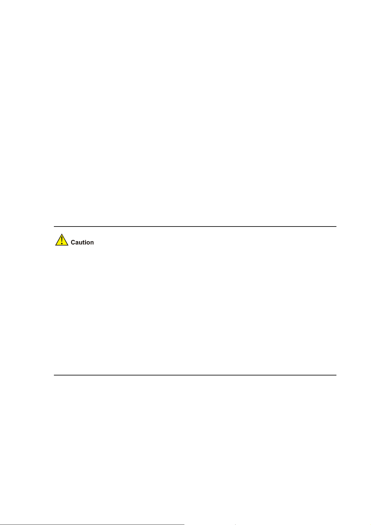
Please set application file type in cf:
M=MAIN B=BACKUP S=SECURE N=NOTYPE
**************************************************************************
NO. Size(B) Time Type Name
0 15561860 Jul-10-2006 14:14 N cf:/main.bin
**************************************************************************
Enter File Name:cf:/main.bin
Select the application program as the main boot file, and enter its complete path and file name.
Modify this file Attribute:
1. +Main
2. -Main
3. +Backup
4. -Backup
5. Exit
Enter your choice(1-5):1
Enter "1" to set the selected application program to be the main boot file, i.e. the default boot file of the
system.
Step 6: Enter <5> to exit to the main BootROM menu. Enter <1 > to boot from the CF card.
z The file in the CF card will be overwritten if the file name being input is the same with the original file
name in the CF card.
z Make sure the space on memory is sufficient. Or, the system prompts insufficient space:
Updating File main.bin
Insufficient CF Card space or failed device writing operation
z The file updated will directly replace the original file of this type to become the only application
program. The main.bin file downloaded here will replace the original M file directly to become the
main boot program.
z Refer to the section “Files” for detailed descriptions of file types.
z Do not include path information in the filename input during upgrade.
z You can set the main/backup attributes for the startup file under the root directory of the device
only.
Maintaining Application Program and Configuration Through Command Lines
After booting the router normally, you can upgrade and backup application program and backup and
recover configurations under command line mode.
Maintaining the Router with TFTP Server
The TFTP service provided by the router is TFTP Client — the router serves as TFTP Client, and the file
server serves as TFTP Server . You can input commands to upload the configuration file and application
5-16
Page 62

program of the router to the file server, or download configuration file or application program to the
router from the file server.
Configuring environment
Step 1: Set up hardware environment (refer to section “Upgrading Application Program Through
Ethernet Interface” for details), and point the server path to the folder where the file is put.
Figure 5-8 Networking diagram for maintenance under command line mode
Configure the IP addresses of the two sides to be in the same network. In this section, the TFTP server
is set to 192.168.0.1, and the Ethernet interface connected to it (Ethernet interface 0/0 in this example;
so, any interface is OK) is set to 192.168.0.2. Both can use the ping command to check if the
connection is successful.
Backing up and recovering application program and configure file
After finishing environment building, perform the following operations:
View the files included in current file system with the dir command:
<DEVICE>dir
Directory of cf:/
0 -rw- 14323376 Apr 03 2006 15:36:48 main.bin
1 drw- - Mar 20 2006 09:55:28 logfile
2 -rw- 909 Apr 04 2006 10:54:38 configbak.cfg
3 -rw- 1045 Apr 04 2006 11:31:36 config.cfg
4 -rw- 14323376 Mar 31 2006 17:50:22 backup.bin
63340 KB total (20928 KB free)
File system type of cf: FAT32
<DEVICE>
Use the command as follows to backup the config.cfg file on the router to TFTP server and save as
config.bak:
5-17
Page 63

<DEVICE>tftp 192.168.0.1 put config.cfg config.bak
File will be transferred in binary mode
Sending file to remote tftp server. Please wait... \
TFTP: 1045 bytes sent in 0 second(s).
File uploaded successfully.
Use this command to download the config.cfg file on the server to the router:
<DEVICE>tftp 192.168.0.1 get config.cfg config.cfg
The file config.cfg exists. Overwrite it?[Y/N]:y
Verifying server file...
Deleting the old file, please wait...
File will be transferred in binary mode
Downloading file from remote tftp server, please wait...\
TFTP: 1045 bytes received in 0 second(s)
File downloaded successfully.
If a config.cfg file already exists in the router, select <Y/y> to overwrite it.
z If a config.cfg file already exists on the server, it will be overwritten.
z The above operations are performed under user view.
z The backup configuration file can be modified by text editor. The configuration file modified during
download process can modify the configuration, and the modification takes effect after rebooting.
Similarly, you can also download application program to the router to overwrite the old main
program to upgrade the application program.
Maintaining the Router with FTP Server
Maintaining the router when it serves as the server
FTP (File Transfer Protocol) is an application layer protocol in the TCP/IP suit. It mainly transfers files
among remote hosts. Born over TCP, it provides reliable and connection-oriente d data transfer service
but does not provide access authorization and authentication mechanism.
The FTP service provided by the router is FTP Server , that is to say, the router serves as the FTP Server .
You can run FTP Client to log onto the router and access files on the router.
Install FTP Client before using FTP. No FTP Server is available with the MSR 20 series. You must install
one yourself. Take the FTP Client with Windows XP for example.
Step 1: Build hardware maintenan ce environment as follows:
5-18
Page 64

Figure 5-9 Router maintenance when it serves as the server
Ethernet cable
Router
TFTP/FTP Server
Console cable
PC
TFTP/FTP Client
Configure the IP addresses of the two sides to be in the same network. In this section, the PC server is
set to 192.168.0.1, and the router Ethernet interface connected to it (Ethernet interface 0/0 in this
example; so, any interface is OK) is set to 192.168.0.2. Both can use the ping command to check if the
connection is successful.
Step 2: Boot FTP service.
You can boot FTP service after configuring FTP server authentication and authorization. FTP server
supports multi-user access. The remote FTP user sends request to the FTP server, which then
executes accordingly and returns the result of the execution to user . Use the following command to boot
the FTP service:
[DEVICE]ftp server enable
% Start FTP server
Add FTP authorized user name and password:
[DEVICE] local-user guest
[DEVICE-luser- guest] service-type ftp
[DEVICE-luser- guest] password simple 123456
Step 3: Maintain the router.
After booting FTP service of the router and configuring user name and password, you can boot FTP
Client on your PC. Take the FTP Client with Windows XP for example:
Enter <ftp> in the DOS window, and the system prompts:
C:\Documents and Settings\Administrator> ftp
ftp>
ftp> open 192.168.0.2
Connected to 192.168.0.2.
220 FTP service ready.
User (192.168.0.2:(none)): guest
331 Password required for guest
Password:
230 User logged in.
5-19
Page 65

After you correctly enter the username and password, the system prompts login success, and you can
complete maintenance of the router, for example, modifying transmission mode and local path, and
backing up files. In this example, the main.bin file on the router is backed up to the PC.
ftp> binary
200 Type set to I.
ftp> lcd c:\temp
Local directory now C:\temp.
ftp> get main.bin main.bin
200 Port command okay.
150 Opening BINARY mode data connection for main.bin.
226 Transfer complete.
ftp: 14323376 bytes received in 16.81Seconds 851.87Kbytes/sec.
Recover the backup file to the router command:
ftp> put main.bin main.bin
200 Port command okay.
150 Opening BINARY mode data connection for main.bin.
226 Transfer complete.
ftp: 14323376 bytes sent in 8.29Seconds 1727.37Kbytes/sec.
ftp> quit
221 Server closing.
Maintaining the router when it serves as the client
You can also maintain the router file system by building FTP server and making the router serve as the
client.
Step 1: Build maintenance environment as follows:
Figure 5-10 Router maintenance when it serves as the client
When the router serves as the client, you can run FTP server program on your PC as the FTP server,
and set the server path. Then, add user name and p assword for the router.
Configure the IP addresses of the two sides to be in the same network. In this section, the FTP server is
set to 192.168.0.1, and the Ethernet interface connected to it (Ethernet interface 0/0 in this example; so,
5-20
Page 66

any interface is OK) is set to 192.168.0.2. Both can use the ping command to check if the connection is
successful.
Step 2: Maintain the router through the terminal connected to the console port as follow:
<DEVICE>ftp 192.168.0.1
Trying 192.168.0.1 ...
Press CTRL+K to abort
Connected to 192.168.0.1.
220 3Com 3CDaemon FTP Server Version 2.0
User(192.168.0.1:(none)): guest
331 User name ok, need password
Password:
230 User logged in
[ftp]
Use the command as follows to maintain the router.
Here, get and put commands are used to backup and recover files.
[ftp] get main.bin main.bin
cf:/main.bin has been existing. Overwrite it?[Y/N]:y
200 PORT command successful.
150 File status OK ; about to open data connection
226 Closing data connection; File transfer successful.
FTP: 14323376 byte(s) received in 69.256 second(s) 206.00K byte(s)/sec.
[ftp]put main.bin main.bin
200 PORT command successful.
150 File status OK ; about to open data connection
226 Closing data connection; File transfer successful.
FTP: 14323376 byte(s) sent in 15.974 second(s) 896.00Kbyte(s)/sec.
[ftp]quit
221 Service closing control connection
Maintaining Application Program and Configuration File
You can modify and display the file type under the file control submenu:
Enter <4> under the main BootROM menu to enter the file control submenu. The system prom pts:
========================<File CONTROL>=======================
|Note:the operating device is CF Card |
| <1> Display All File |
| <2> Set Application File type |
| <3> Set Configuration File type |
| <4> Delete File |
| <5> Exit To Main Menu |
=============================================================
Enter your choice(1-5):
Display all files
Enter <1>, and the system prompts:
5-21
Page 67

Display All File In cf:
**************************************************************************
NO. Size(B) Time Name
0 14323376 Mar-23-2006 11:47 cf:/main.bin
1 14144592 Mar-17-2006 19:39 cf:/d13.bin
2 935 Mar-23-2006 15:39 cf:/config.cfg
3 160 Mar-20-2006 09:55 cf:/private-data.txt
4 14323456 Mar-25-2006 10:38 cf:/secure.bin
5 238664 Mar-27-2006 10:50 cf:/logfile/logfile.log
**************************************************************************
Set application file type
Enter <2> under the file control submenu to enter the set application file type menu:
Please set application file type in cf:
M=MAIN B=BACKUP S=SECURE N=NOTYPE
**************************************************************************
NO. Size(B) Time Type Name
0 14323376 Mar-23-2006 11:47 M cf:/main.bin
1 14144592 Mar-17-2006 19:39 B cf:/d13.bin
2 14323456 Mar-25-2006 10:38 S cf:/secure.bin
**************************************************************************
Enter File Name:
Enter the file name, including device type and extension name. Take cf:/main.bin for example. Enter the
complete file name, press <ENTER>, and then the system prompts to modify the file type:
Enter File Name:cf:/main.bin
Modify this file Attribute:
1. +Main
2. -Main
3. +Backup
4. -Backup
5. Exit
Enter your choice(1-5):
You can set the file type to +M, -M, +B and -B by entering 1 to 4. Refer to section 0 “Introduction” for
details.
Set configuration file type
Enter <3> under the file control submenu to enter the configuration file type menu.
Please set configuration file type in cf:
M=MAIN B=BACKUP N=NOTYPE
**************************************************************************
NO. Size(B) Time Type Name
0 14323376 Mar-23-2006 11:47 M cf:/router.cfg
1 14144592 Mar-17-2006 19:39 B cf:/a.cfg
2 14323456 Mar-25-2006 10:38 N cf:/b.cfg
5-22
Page 68

Delete files
**************************************************************************
Enter File Name:
Enter the file name, including device type and extension name. Take cf:/router.cfg for example. Enter
the complete file name, press <ENTER>, and then the system prompts to modify the file type:
Enter File Name: cf:/router.cfg
Modify this file Attribute:
1. +Main
2. -Main
3. +Backup
4. -Backup
5. Exit
Enter your choice(1-5):
You can set the operation file to the types of M, Cancel M, B and Cancel B by entering 1-4. Refer to
section “
Configuration file” for details.
Enter <4> under the file control submenu to delete files:
Delete All File In cf:
**************************************************************************
NO. Size(B) Time Name
0 14323376 Mar-23-2006 11:47 cf:/main.bin
1 14144592 Mar-17-2006 19:39 cf:/d13.bin
2 935 Mar-23-2006 15:39 cf:/config.cfg
3 160 Mar-20-2006 09:55 cf:/private-data.txt
4 14323456 Mar-25-2006 10:38 cf:/secure.bin
5 238664 Mar-27-2006 10:50 cf:/logfile/logfile.log
**************************************************************************
Enter File Name:
Enter the file name, press <ENTER>, and then the system prompts deleting success:
deleting...
success!
z Confirm the file to be deleted before deleting since the system does not prompt you to confirm
when deleting files.
z You can set the main/backup attributes for the application and configuration file under the root
directory only, and the complete path name of the set application file cannot exceed 6 3 characters.
Exit to the main menu
Exit to the main BootROM menu.
5-23
Page 69

Dealing with Router Password Loss
Do as follows when your BootROM password, user password or Super Passwo rd is lost.
User Password Loss
You cannot enter the system if you lose your user password. You can boot the system by neglecting
system configuration. Perform the following operations:
Step 1: Enter the main BootROM menu, and sele ct <6 > to boot by ignoring system configuration:
The system prompts:
........
Flag Set Successfully.
The system prompts set success.
Step 2: When the main BootROM menu appears again, enter <a> to reboot the system.
........
system start booting......Version 2.11
Step 3: Set new password under the system view after rebooting.
[DEVICE] user-interface console 0
[DEVICE-ui-console0] authentication-mode password
[DEVICE-ui-console0] set authentication password simple 123456
This indicates that the password authentication is adopted at the Console port and the password is set
to 123456 and stored in plain text.
z After rebooting, the system runs with the initial default configuration. The original configuration files
are stored in memory. To restore the original configurations, you can use the display
saved-configuration command to display them, and then copy and execute them.
z When storing the password in plain text, you can use the display current-configuration
command to see the password in the current configuration. If you use the set authentication
password cipher 123456 command when setting the password, the password is encrypted and
stored.
Step 4: Save the new configuration.
[DEVICE] save
Execute the save command after modifying the user password to save the new password.
5-24
Page 70

BootROM Password Loss
Contact the agent or our technical su pport personnel in the event of BootROM passwo rd loss. They can
help you set a new password
Modify the BootROM password under the main BootROM menu.
Enter <5> to modify the password following the prompt. The console terminal displays:
Change password.
Old password:
New password:
Verify:
........Password Set Successfully.
The password modification fails when old password is not correct or new password is not correctly
entered, and then the system exits this operation.
Super Password Loss
The Super Password enables you to switch among the four Super levels. In the event of Super
Password loss, you cannot perform the operations requiring higher right.
Enter <8> under the main BootROM menu to clear the Super Password.
Select this option, quit the menu and reboot the router. You can directly enter the system view. Only
after the first rebooting will the setting take effect (the Super Password restores after the second
rebooting).
Backing up and Restoring BootROM
Enter <7> under the main BootROM menu to enter the BootROM operation submenu. Refer t o section
BootROM operation submenu” for details.
“
Enter <1> under the menu, and the system starts to backup the entire BootROM. The system prom pt s:
Backuping BootRom....
Updating the backup Basic BootRom.......
Backuping Basic BootRom Success!
Updating Back Extended BootRom..........
Backuping Extended BootRom Success!
Now, the entire BootROM is ba cked up to the memory.
Enter <2> under the menu to restore the BootROM in the memory to the system:
Restore Basic BootRom
Updating the Norm Basic BootRom..............
Restore Basic Bootrom Success!
Restore Extended BootRom
Updating Extended BootRom..............
Restore Extended Bootrom Success!
5-25
Page 71

Table of Contents
6 Hardware Maintenance ·····························································································································6-1
Preparing Tools·······································································································································6-1
Opening/Closing Chassis Cover·············································································································6-1
Internal Structure·····································································································································6-3
Installing/Removing CF Card··················································································································6-4
Structure··········································································································································6-4
Installing CF Card····························································································································6-4
Removing CF Card··························································································································6-4
Replacing Memory Bar····························································································································6-5
Memory Bar Structure ·····················································································································6-6
Memory Bar Slot······························································································································6-6
Installing/Removing Memory Bar ····································································································6-6
Installing/Removing ESM/VCPM Card····································································································6-7
i
Page 72
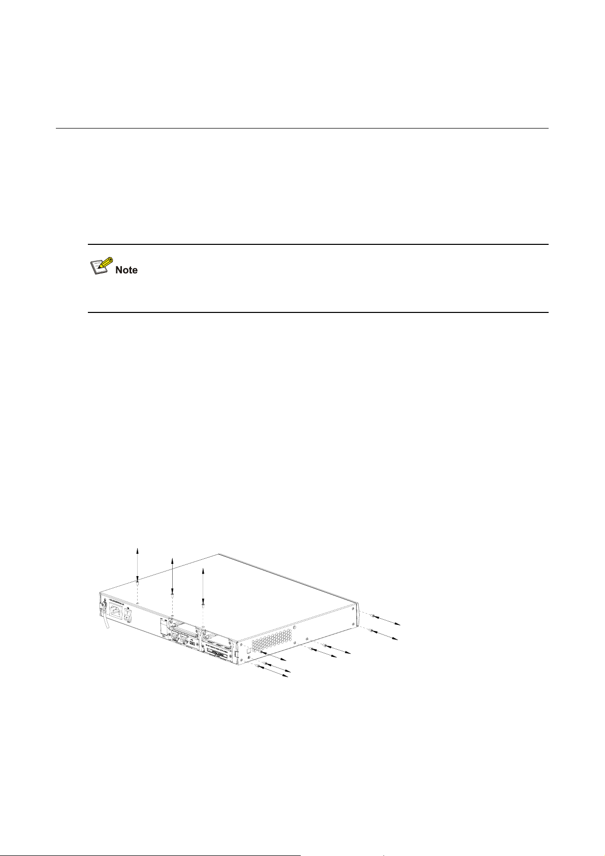
6 Hardware Maintenance
Preparing Tools
z Phillips screwdriver
z Straight screwdriver
z ESD-preventive twist strap
z Static shielding bag
The tools are not available with the MSR 20 series. You must prepare one yourself.
Opening/Closing Chassis Cover
Step 1: Power off the router and remove the power cord.
Step 2: Remove all cables of interface modules on the back panel (keep the ground cable connected).
Step 3: Put the router on level ground and have the back panel face you. Loosen the captive screws
fastening the back panel with Phillips screwdriver.
Step 4: Put two straight screwdrivers into the holes on the two sides of the chassis and turn them until
the tab on the front edge is separated from the front p anel.
Step 5: Drag the chassis le velly a little towards your body and lift it, and the n you can rem ove the cover
and put it away.
Figure 6-1 Remove/install captive screws of MSR 20-20/20-21
6-1
Page 73

Figure 6-2 Turn the screwdriver in the hole on MSR 20-20/20-21
Figure 6-3 Remove/install captive screws of MSR 20-40
Figure 6-4 Turn the screwdriver on MSR 20-20/20-21
z On a mounting screw of your router chassis, there is an anti-dismantle seal of our company. You
must keep it in good condition when asking your sales agent for servicing. You can open the
chassis yourself but with permission of your sales agent and must operate following the related
rules. The company is not liable for any damage or consequence resulted from users' operation
without permission.
z Do not replace the hardware unless necessary and under the guidance of technical staff.
z Ensure that no electricity is present before servicing the device to avoid bodily injuries.
z Wear an ESD-preventive wrist strap when servicing the device, making sure it has good
skin-contact.
z Use the memory bars provided by our company. only. Otherwise, anomalies might occur to the
device.
6-2
Page 74

Internal Structure
Figure 6-5 Internal structure of MSR 20-20/20-21
(1) Power module (2) Memory bar slot
(3) ESM slot (4) Fan module
(5) SIC slot1 (6) SIC slot2
Figure 6-6 Internal structure of MSR 20-40
(5)
(4)
(3)
(2)
(1)
(6)
(7)
(8)
(9)
(1) Power module (2) CF c ard slot
(3) SDRAM slot (4) ESM slot0
(5) ESM slot1 (6) SIC slot
(7) Fan (8) VCPM slot
(9) VPM slot
6-3
Page 75

Installing/Removing CF Card
Structure
Figure 6-7 Front view of CF card
Installing CF Card
Install the CF card following these steps:
Step 1: Push the spring button into the slot completely, and make sure it only springs out with outside
force.
Step 2: Press the CF card into the slot in correct orientation, and make sure it only springs out with
outside force.
Figure 6-8 Press the CF card into the slot
Make sure the CF card with correct application program is properly installed in the slot; or, the system
cannot boot.
Removing CF Card
Remove the CF card following these steps:
Step 1: Check the CF card LED to make sure it is not blinking, and then proceed.
Step 2: Press the spring bu tton to release the internal spring clip, makin g the card out of the slot a little.
Step 3: Push the spring button hard in the orient ation shown in the figure below, and the CF card on the
right springs out a little. Then, take it out.
6-4
Page 76
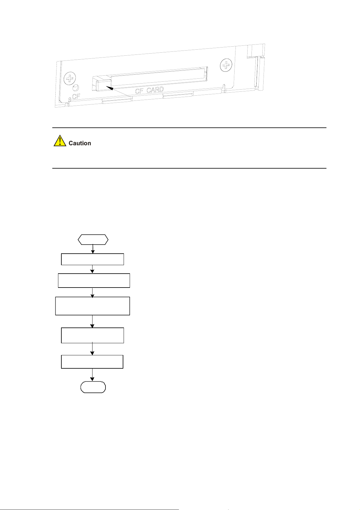
Figure 6-9 Press the spring button to make the card spring out
Do not remove the card when the router is booting or the LED is blinking to avoid hardware damage.
Replacing Memory Bar
This section describes how to replace a memory bar. See the following flow.
Figure 6-10 Memory bar maintenance flow
Start
Start
Prep ar e tools
Prep ar e tools
Tur n off th e pow er switch
Tur n off th e pow er switch
Locat e the me mory bar
Locat e the me mory bar
on t he main boar d
on t he main boar d
Remove t he memory b ar
Remove t he memory b ar
Install the memory bar
Install the memory bar
End
End
Memory bars are main board components that you can expand or upgrade as needed. Generally, you
need to do that in the following situations:
z More memory is required for the updated application program, maintaining a large routing table, or
processing tasks that consume large memory.
z The existing memory bar is damaged.
6-5
Page 77

z Hold the memory bar by its edge and avoid touching the components on its surface. An improper
operation might result in damage.
z It is normal that you feel hard when removing the memory bar, but do not overexert.
z Use the memory bars provided by our company. only. Otherwise, anomalies might occur to the
device
Memory Bar Structure
Figure 6-11 Memory bar structure
Memory Bar Slot
Figure 6-12 Memory bar structure
Installing/Removing Memory Bar
Follow the steps below to install the memory bar:
Step 1: Make sure all power interfaces are shut down, and then proceed.
Step 2: Align the memory bar golden finger with the slot on the main board.
Step 3: Make the memory bar to form an angle of 45 degrees with the main board and insert it into the
slot.
Step 4: Press the memory bar vertically until you hear a click. This indicates the memory bar is fixed
within the slot.
Step 5: Check if the spri ng clip has locked the memory bar slot.
6-6
Page 78

Figure 6-13 Install memory bar into the slot
Follow the steps below to remove the memory bar:
Step 1: Make sure all power interfaces are shut down, and then proceed.
Step 2: Press the spring clips on the two sides of the memory bar, and pull outwards levelly until the
memory bar separates with the spring clips a nd forms an angle of 45 degrees with the main board.
Step 3: Remove the memory bar.
Figure 6-14 Remove memory bar from the slot
Installing/Removing ESM/VCPM Card
Follow the steps below to install the ESM/VCPM card:
Step 1: Make sure all power interfaces are shut down, and then proceed.
Step 2: Open the chassis cover (refer to section “
card.
Step 3: Install the card bracket on specified position on the main board, and fasten it on the board.
Step 4: Align the card interface with the slot and press down vertically to install the card on the board.
Then, align the screw eye with the card bracket.
Step 5: Fasten the card on the bracket with dedicated screws, making sure the card is level and firm.
Opening/Closing Chassis Cover” for det ails) to find the
6-7
Page 79

Step 6: Install the cover and power it on.
Figure 6-15 Install card bracket
Figure 6-16 Fasten the card on the bracket with screws
Perform the steps inversely to remove the card.
6-8
Page 80

Table of Contents
7 Troubleshooting ········································································································································7-1
Troubleshooting the Power System········································································································7-1
Troubleshooting the Configuration System·····························································································7-1
Troubleshooting Application Software Upgrade ·····················································································7-1
i
Page 81

7 Troubleshooting
Troubleshooting the Power System
Symptom:
The PWR LED on the PSU is OFF.
Solution:
Check that:
z The power switch on the router is turned on
z The switch of the power source is turned on
z The power cord is correctly connected
z The power source meets the requirement of the router
Troubleshooting the Configuration System
If the router passes POST after powered on, the console screen displays the startup banner; if faults
occur to the configuration system, the console screen displays nothing or only illegible characters.
Symptom 1:
After the router is powered on, the console screen displays nothing.
Solution:
Step 1: Check that:
z The power system is normal.
z The console cable is correctly connected.
Step 2: Check the console cable and the terminal (HyperTerminal for example) settings.
Symptom 2:
After the router is powered on, the console screen displays illegible characters.
Solution:
Verify that the terminal settings are as follows:
Baud: 9600
Data bits: 8
Stop bit: 1
Parity: None
Flow control: None
Terminal emulation: VT100
Reconfigure the parameters if their values are differe nt.
Troubleshooting Application Software Upgrade
Symptom 1:
7-1
Page 82

When upgrading the software using TFTP, the system displays:
boot device : motfcc
unit number : 1
processor number : 0
file name : main.bin
inet on ethernet (e) : 192.168.0.2
host inet (h) : 192.168.0.1
user (u) : guest
ftp password (pw) : 123456
flags (f) : 0x80
Loading...
Done!
0 bytes downloaded.
Something wrong with the file.
Solution:
Fault occurs because the source file does not exist, the network cable is not connected, or the IP
address of the PC is incorrect. Make sure that the source file is in the TFTP root directory, the cable is
connected securely, and the IP address is set correctly.
Symptom 2:
When upgrading the software using TFTP, the system displays:
boot device : motfcc
unit number : 1
processor number : 0
file name : main.bin
inet on ethernet (e) : 192.168.0.2
host inet (h) : 192.168.0.1
user (u) : guest
ftp password (pw) : 123456
flags (f) : 0x80
Loading...
Done!
11487495 bytes downloaded.
Something wrong with the file.
Solution:
Fault occurs because an incorrect application file is downloaded. Download the correct application
program file.
7-2
Page 83

z The bar code labels on the chassis and the FICs contain information about production and
servicing. Before you ask your agent for servicing, provide its bar code.
z If you do not set the parameters such as the host name and gateway, they will not be displayed
when you upgrade the router. Therefore, the terminal display will be different from the above
symptoms.
7-3
 Loading...