

Page 1
®
MSH S
SER
U
G
WITCH
UID
E
1005
Part No. DUA1840-0AAA01
Published June 1996
Page 2

3Com Corporation ■
© 3Com Ireland, 1996. All rights reserved. No part of this documentation may be reproduced in any form or by
any means or used to make any derivative work (such as translation, transformation, or adaptation) without
permission from 3Com Ireland.
3Com Ireland reserves the right to revise this documentation and to make changes in content from time to time
without obligation on the part of 3Com Ireland to provide notification of such revision or change.
3Com Ireland provides this documentation without warranty of any kind, either implied or expressed, including,
but not limited to, the implied warranties of merchantability and fitness for a particular purpose. 3Com may
make improvements or changes in the product(s) and/or the program(s) described in this documentation at any
time.
UNITED STATES GOVERNMENT LEGENDS:
If you are a United States government agency, then this documentation and the software described herein are
provided to you subject to the following restricted rights:
For units of the Department of Defense:
Restricted Rights Legend:
subparagraph (c) (1) (ii) for restricted Rights in Technical Data and Computer Software clause at 48 C.F.R.
52.227-7013. 3Com Ireland, c/o Isolan House, Brindley Way, London Road, Hemel Hempstead, Herts., HP3 9XJ,
United Kingdom.
For civilian agencies:
Restricted Rights Legend: Use, reproduction or disclosure is subject to restrictions set forth in subparagraph (a)
through (d) of the Commercial Computer Software - Restricted Rights Clause at 48 C.F.R. 52.227-19 and the
limitations set forth in 3Com Corporation’s standard commercial agreement for the software. Unpublished rights
reserved under the copyright laws of the United States.
If there is any software on removable media described in this documentation, it is furnished under a license
agreement included with the product as a separate document, in the hard copy documentation, or on the
removable media in a directory file named LICENSE.TXT. If you are unable to locate a copy, please contact 3Com
and a copy will be provided to you.
Unless otherwise indicated, 3Com registered trademarks are registered in the United States and may or may not
be registered in other countries.
3Com, LinkBuilder and Transcend are registered trademarks of 3Com Corporation. SuperStack II, PACE, VLT,
Virtual LAN Trunk and 3TECH are trademarks of 3Com Corporation. 3ComFacts is a service mark of 3Com
Corporation.
CompuServe is a registered trademark of CompuServe, Inc..
Other brand and product names may be registered trademarks or trademarks of their respective holders.
5400 Bayfront Plaza ■
Use, duplication or disclosure by the Government is subject to restrictions as set forth in
Santa Clara, California ■
95052-8145
Page 3

ONTENTS
C
BOU
A
Introduction 1
How to Use This Guide 1
Conventions 2
Related Publications 3
1
G
About the LinkBuilder MSH 1-1
About the MSH Switch 1005 1-1
Switch Operation and Features 1-5
MSH Switch 1005 on Your Network 1-11
T THIS GUID
ETTIN
G STARTE
Summary of Features 1-2
Port Connections 1-3
10BASE-T Switch Ports 1-3
Internal Switch Ports 1-3
Transceiver Module Ports 1-4
The Backbone Port 1-4
Adding an Expansion Module 1-4
How the Switch Compares to a Bridge 1-5
Forwarding of Packets 1-5
Intelligent Flow Management 1-7
Full Duplex 1-8
Security 1-8
Resilient Links 1-8
Virtual LANs (VLANs) 1-8
PAC E 1 -9
Server Connections 1-11
E
D
Page 4

Network Configuration Examples 1-11
Configuration Rules for Fast Ethernet 1-15
Configuration Rules with Full Duplex 1-15
Switch Overview — Front Panel 1-16
LEDs 1-17
Transceiver Module slot 1-18
10BASE-T Ports 1-18
Switch Overview — PCB View 1-19
Transceiver Module Connector [1] 1-19
Expansion Module Fixing Posts [2] 1-20
Links LK 1 to LK 5 [3] 1-20
Expansion Module Socket [4] 1-20
Backplane Connectors [5] 1-20
Switch Defaults 1-20
Setting Up the MSH Switch 1005 for Management 1-21
NSTALLATION AND INITIA
2
I
Safety Information 2-1
Pre-installation Configuration 2-2
Setting the Links on the Switch 1005 2-2
Advice for Setting Backplane Connections and Avoiding Loops 2-4
Fitting a Transceiver Module 2-5
Fitting an Expansion Module 2-5
Switch 1005 Installation and Removal 2-6
Installing the Switch 1005 2-6
Removing the Switch 1005 2-7
Operation after Power-up 2-7
In an Unmanaged System 2-7
In a Managed System 2-8
Setting up the Switch 1005 2-9
Using the VT100 Interface 2-9
Using Telnet 2-12
Using an SNMP Network Manager 2-12
Accessing the Switch 1005 VT100 Interface 2-13
L SETU
P
Page 5

Logging On 2-14
After Logging On 2-15
Switch 1005 Management Setup 2-17
Logging Off 2-19
Auto Logout 2-19
Setting Up Users 2-20
Creating a New User 2-21
Deleting a User 2-22
Editing User Details 2-23
Assigning Local Security 2-24
WITCH CONFIGURATIO
3
S
Choosing a Switch Management Level 3-1
Switch 1005 Setup 3-4
Port Setup 3-7
Specifying the Backbone Port 3-11
The Switch Database (SDB) 3-12
Configuring the Switch Database 3-14
Searching the Switch Database 3-15
By MAC Address 3-15
By Port 3-15
Adding an Entry into the SDB 3-16
Deleting an Entry from the SDB 3-16
Resilient Links 3-17
Viewing Resilient Setup 3-18
Configuring Resilient Links 3-20
Creating a Resilient Link 3-22
Deleting a Resilient Link 3-22
Setting Up Traps 3-23
Resetting the Switch 1005 3-25
Initializing the Switch 1005 3-26
Upgrading Software 3-28
N
Page 6

DVANCED MANAGEMENT
4
A
Virtual LANs (VLANs) 4-1
What are VLANs? 4-1
Benefits of VLANs 4-2
An Example 4-3
VLANs and the Switch 1005 4-4
The Default VLAN 4-4
Connecting VLANs to a Router 4-4
Connecting Common VLANs Between Switches 4-5
Using Non-routable Protocols 4-5
Using Unique MAC Addresses 4-5
VLAN Configurations 4-6
Example 1 4-6
Example 2 4-8
Example 3 4-10
Setting Up VLANs on the Switch 4-12
Assigning a Port to a VLAN 4-15
Specifying a Backbone Port 4-15
Specifying that a Backbone Port is Part of a VLT 4-15
TATUS MONITORING AND STATISTICS
5
S
Summary Statistics 5-2
Port Statistics 5-4
Port Traffic Statistics 5-6
Port Error Analysis 5-9
Status Monitoring 5-11
Remote Polling 5-13
ROBLE
6
P
Spot Checks 6-1
Identifying Fault Conditions with the LEDs 6-2
VT100 Problems 6-3
Switch 1005 Operation Problems 6-4
M SOLVIN
G
Page 7

CREEN ACCESS RIGHTS
A
S
ECHNICA
B
T
ECHNICA
C
T
Online Technical Services C-1
3Com Bulletin Board Service C-1
World Wide Web Site C-2
3ComForum on CompuServe C-3
3ComFacts Automated Fax Service C-3
Support from Your Network Supplier C-4
Support from 3Com C-5
Returning Products for Repair C-6
LOSSARY
G
NDE
I
IMITE
L
L SPECIFICATIO
L SUPPOR
Access by Modem C-1
Access by ISDN C-2
X
D WARRANTY
T
N
Page 8

Page 9

A
BOU
T THIS
Introduction
This guide describes how to install and configure the MSH Switch 1005.
If the information in the release notes shipped with your product differs
from the information in this guide, follow the release notes.
How to Use This Guide
The following table shows where to find specific information in this
guide.
G
UID
E
If you are looking for:
A description of all the Switch 1005 features and a guide to making a
quick start with management
Important safety information, a brief overview of the installation process
and a complete guide the initial setup required
Information and steps telling you how you can manage the Switch 1005
using the VT100 screens
Information on the more advanced functionality you can manage using
the VT100 screens
Details on viewing Switch 1005 statistics using the VT100 screens
Ideas on solving problems should they arise
A list of user access rights for the VT100 screens
Technical information about the Switch 1005
Technical support information
A list of terms and definitions used in this Guide
A comprehensive Index
Turn to:
Chapter 1
Chapter 2
Chapter 3
Chapter 4
Chapter 5
Chapter 6
Appendix A
Appendix B
Appendix C
Glossary
Index
Page 10
BOU
A
T THIS GUID
2
Conventions
Tabl e 1
throughout this guide:
E
and
Table 2
list text and icon conventions that are used
Table 1
Icon
Table 2
Convention
“Enter” vs. “Type”
Text represented as
screen
display
Text represented as
commands
Keys
Italics
Notice Icons
Type
Information Note
Caution
Warning
Tex t Conventi o ns
Description
Information notes call attention to
important features or instructions.
Cautions alert you to personal safety risk,
system damage, or loss of data.
Warnings alert you to the risk of severe
personal injury.
Description
When the word “enter” is used in this guide, it means type
something, then press the Return or Enter key. Do not press
the Return or Enter key when an instruction simply says “type.”
This typeface
appear on your terminal screen, for example:
NetLogin:
This typeface
you enter, for example:
SETDefault !0 -IP NETaddr = 0.0.0.0
When specific keys are referred to in the text, they are called
out by their labels, such as “the Return key” or “the Escape
key,” or they may be shown as [Return] or [Esc].
If two or more keys are to be pressed simultaneously, the keys
are linked with a plus sign (+), for example:
Press [Ctrl]+[Alt]+[Del].
Italics
are used to denote
is used to represent displays that
is used to represent commands that
new terms
or
emphasis
.
Page 11

Related Publications
This User Guide is not intended to answer all your questions
concerning the MSH. While using the MSH Switch 1005, you may need
to refer to the following publications:
■
LinkBuilder MSH User Guide
■
LinkBuilder MSH Management Module User Guide
DUA1850-0AAA0x.
Related Publications
, part number DUA1800-0AAA0x.
, part number
3
Page 12

BOU
A
T THIS GUID
4
E
Page 13

1
ETTIN
G
G STARTE
About the LinkBuilder MSH
The LinkBuilder MSH is an extremely versatile, chassis-based hub that
allows you to connect and manage large, mixed-technology,
mixed-media LANs.
The basis of the MSH is the chassis into which you can install a series of
network-specific modules. Modules within the chassis connect to a
number of backplanes allowing communication between the various
LANs and LAN segments connected to the MSH.
About the MSH Switch 1005
The MSH Switch 1005 is designed to be installed into the MSH chassis,
so that you can extend your network beyond the limits of a repeater
and provide your users with greater bandwidth, faster throughput, and
high speed connections.
D
The MSH Switch 1005 is an intelligent module with its own on-board
management agent. This means that even in an unmanaged MSH
chassis, you can access the manageable features of the Switch using a
Telnet application or an SNMP Network Manager and configure internal
port connections using the five links located on the Switch.
With a Management Module installed into your MSH chassis, you have
access to the VT100 interface of the Switch. This interface provides a
series of ASCII character-based forms which allow you to configure the
manageable features of the Switch. Y
about Switch management in
Chapter 2.
ou can find further information
“Setting up the Switch 1005”
in
Page 14

HAPTE
R
ETTIN
1-2
C
1:
G
G STARTE
Summary of Features
■
8 switched 10BASE-T ports
■
Slot for optional Fast Ethernet or 10BASE-T
■
Switched connections to all 3 internal Ethernet backplanes
■
Internal Fast Ethernet backplane
■
Ability to add Expansion Module adding up to three further
M
odules
■
Support for up to 500 end-stations, unlimited stations on backbone
port
■
Forwarding modes for packets
■
Low latency in fast forward mode
■
No runts in fragment free mode
■
No runts/errors in store-and-forward mode
■
Low latency or no runts/errors in intelligent mode
■
Intelligent Flow Management when packet buffers are full
■
Prevents packets being discarded
■
Suppresses transmissions at source
■
Full duplex on Fast Ethernet Transceiver Modules
■
Security
■
Resilient Link
■
Port-based Virtual LANs (VLANs)
■
Support for up to 16 VLANs on a single Switch 1005
■
Eases the movement of devices on IP networks
■
Controls traffic
■
Provides extra security
■
PACE (Priority Access Control Enabled)
■
Supports multimedia applications over Ethernet
■
Increased Ethernet predictability
■
Full use of network bandwidth
D
Transceiver M
odule
Transceiver
s
DUA1840-0AAA01
Page 15

■
SmartAgent support
■
SNMP with IP and IPX protocols
■
RMON
■
Repeater and Bridge MIB
■
Broadcast storm control
■
Easy software upgrades
■
BOOTP
■
Local management
Port Connections
10BASE-T Switch Ports
Eight fixed ports each configured as MDIX provide 10Mbps bandwidth
to each attached end-station. Maximum segment length is 100m
(328ft) over grade 3, 4 or 5 twisted pair cable.
Internal Switch Ports
As well as switch ports located on the front panel of the Switch 1005,
internal backplane connections provide an additional four switch
ports. These ports are enabled and disabled through management or
using the set of links LK1 to LK5 located on the Switch 1005.
About the MSH Switch 1005
1-3
DUA1840-0AAA01
Three of these ports provide switched connections to the three
10Mbps repeater backplanes located in the MSH chassis, and therefore
to any modules connected to the same backplane.
The fourth internal switched port provides a connection to the Fast
Ethernet backplane, and therefore to any other Switch 1005
module
s
installed in the chassis.
Locating and setting links is described in
Switch 1005”
in Chapter 2.
“Setting the Links on the
Page 16

1-4
HAPTE
R
ETTIN
C
1:
G
G STARTE
D
Transceiver Module Ports
A slot on the front of the Switch 1005 allows you to install any of the
Transceiver M
details in
odules available for this product. You can find more
“Transceiver Module slot”
on page 1-18.
The Backbone Port
The MSH Switch 1005 requires that the port
your network is configured as a
backbone port
connecting
it to the rest of
. This is the port to which
all frames arriving at a switch port with an unknown destination
address will be forwarded. Addresses received on the backbone port
are not stored in the
switch database of the
Switch 1005.
When you first install a Switch 1005 into your MSH chassis, it will
configure its backbone port to be the first Fast Ethernet port it finds
either on the Switch, or on the Expansion Module if fitted. You can
change your designated backbone port to be any switch port (internal
or external). Changing the default backbone port is described in
“Specifying the Backbone Port”
You
can
only have one backbone port per Switch 1005, unless you
in Chapter 3.
have implemented multiple VLANs on one Switch; in this case you
configure one backbone port per VLAN. You can find more information
about VLANs in
Chapter 4
.
can
Adding an Expansion Module
The MSH Switch 1005 also has provision for installing an Expansion
Module. The Expansion Module has three slots for installing any
combination of the
Module slot”
Transceiver Module
on page 1-18.
s described in
“Transceiver
DUA1840-0AAA01
Page 17

Switch Operation and Features
How the Switch Compares to a Bridge
The table below shows how Switch 1005 operation compares to that of
an IEEE 802.1D bridge:
Switch Operation and Features
1-5
Address Learning
Forwarding Mode
Operation when packet
buffers full
Spanning Tree
Action on Unknown
Destination Address
Database size
In all other ways, MSH Switch 1005 and bridge operation is identical.
Forwarding of Packets
The table below shows how a packet is processed when it arrives at the
Switch 1005
Packet Source
Any port EXCEPT backbone port
(Unicast packet)
Any port EXCEPT backbone port
(Unicast packet)
Any port EXCEPT backbone port
(Unicast packet)
:
IEEE 802.1D Bridge
All ports
Store-and-forward
Discard packets
Supported
Flood all ports
Variable
Destination Address
Unknown
Same port as source
address
Another port (not
backbone port)
Switch 1005
All ports except backbone.
Fast Forward, Fragment
Free, Store and Forward, or
Intelligent
Invoke Intelligent Flow
Management to suppress
transmissions at source
Not supported
Forward to backbone port
only
500 addresses
Action
Forward to backbone
port only
Filter (discard)
Forward to specific port
only
DUA1840-0AAA01
Page 18

1-6
HAPTE
C
R
ETTIN
1:
G
G STARTE
D
Packet Source
Any port EXCEPT backbone port
(Multi/Broadcast packet)
Backbone port (Unicast packet)
Backbone port (Unicast packet)
Backbone port
(Multi/Broadcast packet)
Destination Address
Not applicable
Unknown
Known on a port (not
backbone port)
Not applicable
Action
Forward to all ports
(including backbone
port) within same VLAN
as source port
Filter (discard)
Forward to specific port
only
Forward to all ports
within specific VLAN
To best suit your networking requirements, the Switch 1005 allows you
to set one of four frame forwarding modes:
■
Fast Forward
— In this mode, frames are forwarded as soon as the
destination address is received and verified. The forwarding delay, or
latency, for all frames in this mode is just 40µs but with the lack of
checking time, any collision fragments or error frames received are
propagated through the switch.
■
Fragment Free
— In
this
mode, a minimum of 64 bytes of the
received frame is buffered prior to the frame being forwarded. This
ensures that collision fragments are not propagated through the
network, however, CRC errors are forwarded. The forwarding delay, or
latency, for all frames in this mode is 64µs.
■
Store and Forward
— In this mode, received packets are buffered in
their entirety prior to forwarding. This ensures that only good frames
are passed to their destination. The forwarding delay for this mode
varies between 64µs and 1.2ms, depending on frame length. In Store
and Forward mode, latency is measured as the time between receiving
the last bit of the frame, and transmitting the first bit. For the Switch
1005, this is 8µs.
■
Intelligent
— In this mode, the Switch 1005 monitors the amount of
error traffic on the network and changes the forwarding mode
accordingly. If the Switch 1005 detects less than 18 packets per second
with errors, it will operate in Fast Forward mode. As soon as the Switch
1005 detects more than 18 packets per second with errors, it will
operate in Store and Forward mode until the error count returns to 0.
DUA1840-0AAA01
Page 19

Intelligent Flow Management
Switch Operation and Features
1-7
Intelligent Flow Management
(IFM)
is a congestion control mechanism
built into the Switch 1005. Congestion is caused by one or more
devices sending traffic to a Switch port which is already busy. The
Switch 1005 contains both input and output packet buffers and while
congestion is rare, IFM is designed to alleviate problems during those
moments when packet buffers in the Switch 1005 are full. IFM will
prevent packet loss by inhibiting the transmitting device from sending
any further packets until the port is no longer congested.
If a packet arrives at a conventional switch that does not operate IFM,
and that port is congested, the transmitting device is unaware of this
until it times out and decides that the receiving station is not going to
respond to the message. This can take as long as 30 seconds, and
depending on the protocol you are running, may not happen until
many packets have been sent. The transmitting device then has to
retransmit the packets, effectively wasting bandwidth.
Switch
modules
implementing IFM are aware of congestion, and
prevent packet loss by inhibiting the transmitting device from
transmitting the packet in the first place. It does this by forcing the
device to retransmit the packet later. This “back-off” and retransmission
happens very quickly (typically less than one second) and is much
faster than waiting for the transmitting device to time-out. There are
two benefits:
■
■
DUA1840-0AAA01
the packet is transmitted quickly and successfully
the packet is only transmitted once, thereby saving bandwidth.
IFM is designed to be enabled on ports connected to a single network
device. If IFM is enabled on a port connected to multiple devices
through a repeater, packet congestion within the Switch 1005 could
result in packet transmission between two devices connected to the
repeater being inhibited.
Page 20

HAPTE
1-8
R
C
1:
Full Duplex
The MSH Switch 1005 provides full duplex support for any Fast Ethernet
Transceiver Module
to be transmitted and received simultaneously and, in effect, doubles
the bandwidth available on the link. Full duplex also supports
100BASE-FX cable runs of up to 2km.
Security
The MSH Switch 1005 contains advanced security features which
guard against users connecting unauthorized stations onto your
network. When security is enabled on a port, that port enters into a
single address learning mode. This port is then permitted to learn just a
single Ethernet address and once this is learned, if a different address is
then seen on that port, the port will be disabled. Until security is
disabled, no other address can be learned.
Resilient Links
The Resilient Link feature in the Switch 1005 enables you to protect
critical links and prevent wasteful network downtime should that link
fail. Setting up resilience ensures that should a main communication
link fail, a standby duplicate link will immediately and automatically
take over the task of the main link. Each main and standby link pair is
referred to as a resilient link pair. The main and standby links must be
set up on the same Switch 1005.
G
ETTIN
G STARTE
D
s you may have installed. Full duplex allows frames
Virtual LANs (VLANs)
The Switch 1005 has a Virtual LAN (VLAN) feature which allows you to
build your network segments without being restricted by physical
connections.
topology-independent devices that communicate as if they are on the
same physical LAN.
A VLAN is defined as a group of location- and
DUA1840-0AAA01
Page 21

Switch Operation and Features
Implementing VLANs on your network has three main advantages:
■
Network administration personnel are required to make less physical
intervention when a workstation has to be moved. Within the VLAN
setup, a group of devices on different floors in a building can be
configured into a common communications group. If a workstation is
moved from VLAN 1 to VLAN 2 for example, the network administrator
only needs to know address information for that device; the physical
location of the port is irrelevant.
■
Use of network resources becomes much more efficient. Each VLAN
can be set up to contain only those devices which need to
communicate with each other. In this way, broadcast storms, the most
common cause of network congestion, can also be avoided.
■
Network security is enhanced. Devices within each VLAN can only
communicate with member devices in the same VLAN. If a device in
VLAN 1 for example, needs to communicate with devices in VLAN 2, it
must be configured to cross the router between them.
1-9
PACE
DUA1840-0AAA01
Further information can be found in
Chapter 4
.
PACE (Priority Access Control Enabled) technology allows multimedia
applications using voice and video traffic to be carried over standard
Ethernet and Fast Ethernet Local Area Networks (LANs). PACE provides
the quality of service that these applications require, reducing latency
to a minimum and prioritizing the multimedia traffic.
Both multimedia and data traffic are improved considerably by
introducing an Ethernet switch into the LAN and attaching each
end-station to its own dedicated 10Mbps switch port. This removes any
contention between different end-stations for the Ethernet bandwidth.
However, when two-way traffic is passing between an end-station and
the switch port, access to the bandwidth can still be unfairly allocated
to traffic in one direction, resulting in poor quality video display. PACE
allocates the available bandwidth fairly to traffic in each direction. In
this way, existing Ethernet adapters and cabling can be used to run
high-quality multimedia sessions across the LAN.
Page 22

1-10
HAPTE
C
R
ETTIN
1:
G
G STARTE
D
You can enable PACE on the whole Switch 1005
module
or on an
individual port. Before configuring PACE, you should refer to sections
“Switch 1005 Setup”
and
“Port Setup”
in Chapter 3.
DUA1840-0AAA01
Page 23

MSH Switch 1005 on Your Network
MSH Switch 1005 on Your Network
Server Connections
When integrating the Switch 1005 into your network, the following
notes on server connections will ensure that it is operating at
maximum efficiency:
■
Ideally ...
... any local server should be connected to the Switch 1005 using a
100Mbps port.
■
If that is not possible ...
... connect the local server to a dedicated 10Mbps port.
■
If that’s not possible and the local server is connected to a repeated
segment where the traffic is mainly local to that segment ...
... disable Intelligent Flow Management (IFM) on the port to which the
repeater is connected.
Whenever you have multiple workstations connected to a single port of
the Switch 1005, we recommend that you disable IFM on that port.
1-11
Network Configuration Examples
The following illustrations show some examples of how the Switch
1005 can be used on your network.
DUA1840-0AAA01
Page 24
1-12
HAPTE
C
R
ETTIN
1:
G
G STARTE
D
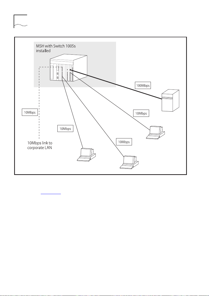
Figure 1-1
Figure 1-1
Workgroup Switch I
shows how the Switch 1005 fits into a large corporate
network with a Fast Ethernet infrastructure. A Switch is positioned on
each floor and servers are centralized in the basement.
DUA1840-0AAA01
Page 25
MSH Switch 1005 on Your Network
1-13
DUA1840-0AAA01
Figure 1-2
Figure 1-2
Workgroup Switch II
shows the Switch 1005 in a second workgroup situation. This
setup could be that of a small office within a large corporation, or part
of a larger corporate network. Each switch port has mainly muliple
end-stations.
Page 26
1-14
HAPTE
C
R
ETTIN
1:
G
G STARTE
D
Figure 1-3
Figure 1-3
Desktop Switch
shows the Switch 1005 used for a group of heavy-traffic
users in a large corporate network. Here, switching is brought to the
desktop with a single end-station per switch port. Local servers are
connected via a 100Mbps Fast Ethernet link.
DUA1840-0AAA01
Page 27

Configuration Rules for Fast Ethernet
Configuration Rules for Fast Ethernet
The topology rules for Fast Ethernet (100Mbps) are slightly different to
those for 10Mbps Ethernet. The key topology rules are:
■
Maximum UTP cable length is 100m (328ft) over
■
A 412m (1352ft) fiber run is allowed for connecting switch to switch, or
end-station to switch, using standards-compliant half-duplex
100BASE-FX.
■
A total network span of 325m (1066ft) is allowed in single-repeater
topologies (one hub stack per wiring closet with a fiber run to the
collapsed backbone); for example, a 225m (738ft) fiber downlink from a
repeater to a router or switch, plus 100m (328ft) UTP run from a
repeater out to the desktops.
Configuration Rules with Full Duplex
The MSH Switch 1005 provides full duplex support for any Fast Ethernet
Transceiver Modules that are installed. Full duplex allows frames to be
transmitted and received simultaneously and, in effect, doubles the
bandwidth available on a link.
category 5
1-15
cable.
■
■
DUA1840-0AAA01
With full duplex, the topology rules are:
Maximum UTP cable length is still 100m (328ft) over
category 5
cable.
A 2km (6562ft) fiber run is allowed for connecting switch to switch, or
end-station to switch.
Page 28
1-16
C
1:
G
G STARTE
D
HAPTE
R
ETTIN
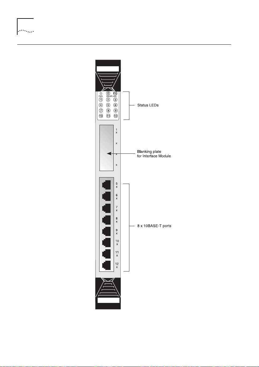
Switch Overview — Front Panel
Figure 1-4
Switch 1005 front view
DUA1840-0AAA01
Page 29

LEDs
Switch Overview — Front Panel
1-17
LED
PWR
(Power)
Backplane
E
FE
1 - 12
(External port
status)
Color
Green
Green flash
(slow, 0.5 Hz)
Green flash
(fast, 1Hz)
Amber
Green
Green flash
Yellow
Green
Green flash
Yellow
Green
Green flash
Yellow
Off
Ports 1 - 4 relate to any Transceiver Module installed into the
slot. If you have installed a Fast Ethernet Transceiver Module,
LED 1 will be lit, all others are unused.
Indicates ...
The Switch is powered up and operating
normally.
Power On Self Test (POST) in operation.
Software download in progress
Fault occurred on this Switch
One or more of the internal Ethernet (10Mbps)
backplanes are enabled.
All three internal Ethernet backplanes are
disabled.
There is network activity on the enabled
backplane(s).
Connection to the internal Fast Ethernet
(100Mbps) backplane is enabled.
Connection to the internal Fast Ethernet
(100Mbps) backplane is disabled.
There is network activity on the Fast Ethernet
backplane.
Link connected; port enabled.
Link connected; port disabled.
Traffic being transmitted/received on this port.
Link not connected.
DUA1840-0AAA01
For information on using the LEDs for fault diagnosis, please see
“Identifying Fault Conditions with the LEDs”
in Chapter 6.
Page 30

HAPTE
R
ETTIN
1-18
C
1:
G
G STARTE
Transceiver Module slot
Allows you to install an Transceiver Module. Transceivers available
include:
■
100BASE-TX Transceiver Module (3C18407)
100Mbps, twisted pair port provides the Switch with a single,
high-speed connection to, for example, your network infrastructure.
Maximum segment length is 100m (328ft) over grade 5 twisted pair
cable.
■
100BASE-FX Transceiver Module (3C18408)
100Mbps, fiber port provides the Switch with a single, high-speed
connection to, for example, your network infrastructure. Use
micron
fiber optic cable with SC connectors. The maximum supported
distance is 412m (1352ft) or 2km
the link support full duplex.
■
4 Port 10BASE-T Transceiver Module (3C18409)
additional four 10BASE-T ports to your Switch 1005 with the same
operating conditions as the eight fixed ports described below.
You should contact your supplier for further details on these and any
further
Transceiver
D
— This Fast Ethernet,
— This Fast Ethernet,
(6562ft)
if the devices at both ends of
Modules available from 3Com.
62.5/125
— Adds an
10BASE-T Ports
Eight fixed ports each configured as MDIX provide the full 10Mbps
bandwidth to each attached end-station. Maximum segment length is
100m (328ft) over grade 3, 4 or 5 twisted pair cable.
DUA1840-0AAA01
Page 31

Switch Overview — PCB View
Switch Overview — PCB View
1-19
Figure 1-5
Switch 1005 PCB view
Transceiver Module Connector [1]
2x
20 pin connector for any of the
DUA1840-0AAA01
“Transceiver Module slot”
Module
s is described in the documentation that accompanies them.
on page 1-18. Installation of the
Transceiver Module
s listed in
Transceiver
Page 32

1-20
C
1:
G
G STARTE
D
HAPTE
R
ETTIN
Expansion Module Fixing Posts [2]
The two threaded posts provide fixing points for an Expansion Module
should you choose to attach one to this Switch.
Links LK 1 to LK 5 [3]
Allow you to configure internal backplane connections for the Switch
1005. See
“Setting the Links on the Switch 1005”
Expansion Module Socket [4]
This socket provides the connection point for an Expansion Module
should you choose to fit one to this Switch.
Backplane Connectors [5]
These connectors engage with the backplane located in the MSH chassis.
Switch Defaults
The following table shows factory defaults for the MSH Switch 1005
in Chapter 2.
:
Port Status
Forwarding Mode
Intelligent Flow Management
(IFM)
PACE
VLANs
Power On Self Test (POST)
RMON
Enabled
Fast Forward
Enabled on external ports
Disabled on internal ports
Disabled (module)
All ports in the Default VLAN (VLAN 1)
Normal
1 Ethernet Statistics session per port/VLAN.
3 Stats History
3 on the Default VLAN
1 Host Table session on the Default VLAN
4 Matrix Table sessions; 1 on the Default VLAN, 1
on port 25, 1 on port 26 and 1 on port 27
4 default alarms per port
Default events for use with the alarm system
sessions on the backbone port and
DUA1840-0AAA01
Page 33

Setting Up the MSH Switch 1005 for Management
Setting Up the MSH Switch 1005 for Management
This section describes how to get started if you wish to use an SNMP
manager. It assumes you are already familiar with SNMP management.
■
If you are using IP and you have a BOOTP server setup correctly on your
network, the IP address for the Switch 1005 will be detected
automatically and you can start managing the Switch 1005 without any
further configuration.
■
If you are using the IPX protocol, the Switch 1005 will be allocated an
IPX address automatically. You can start the SNMP
and begin managing the Switch 1005.
■
If you are using IP without a BOOTP server, you will need to enter the IP
address of the Switch 1005 before the SNMP
communicate with the device. To do this, perform the following steps:
1
Ensure your MSH Management Module is running v4.2 or higher of the
management agent software.
2
Connect a terminal to the serial port located on the MSH front panel.
You can find instructions for doing this in the
Management Module User Guide
, part number DUA1850-0AAA0x.
Network M
Network Manager
LinkBuilder MSH
1-21
anager
can
3
4
DUA1840-0AAA01
Press [Return] one or more times until the MSH Main Banner appears.
The serial port will detect the terminal line speed (baud rate) and
default to:
■
8 data bits
■
1 stop bit
■
no parity
You cannot modify these settings. If your terminal is already setup with
these values, the MSH Main Banner will appear as soon as power-up is
complete. Press [Return] to display the MSH Main Menu.
At the MSH Main Menu, select SERVICE SELECTION. From the Service
Selection list, select Switch 1005. From the Address Table screen,
choose the required Switch 1005 and
Banner
screen
appears.
select MANAGE. The Switch Main
Page 34

1-22
HAPTE
R
ETTIN
C
1:
5
At the Switch 1005 Main Banner, press [Return] to display the Logon
G
G STARTE
screen. Logon using the default name
D
security
, and password
Select OK.
6
The Switch Main Menu is displayed. From this menu, select the
Management Setup option. The Switch Management Setup screen is
displayed.
7
On the Management Setup screen, fill in the following fields:
■
Device IP Address
■
Device SubNet Mask (if necessary)
■
Default Router (if necessary)
security.
For further information on the Management Setup screen, see
1005 Management Setup”
8
If you need the Switch to send SNMP traps to the network manager,
in Chapter 2.
you may need to setup the address of the network manager in the Trap
Table. See
“Setting Up Traps”
in Chapter 3.
3Com Network Managers such as Transcend WorkGroup Manager for
Windows may automatically configure intelligent modules to send traps
to them. Please read the documentation supplied with your network
management software.
9
When you have finished with the Management Setup screen, select OK.
Once the module’s IP parameters are specified, you can continue
management using:
I
n-band management via any SNMP-based Network Manager
■
application.
Out-of-band management via the Switch 1005’s own VT100
■
management interface.
In-band management via the Switch 1005’s own VT100 management
■
interface.
“Switch
DUA1840-0AAA01
Page 35

2
NSTALLATION AND INITIA
I
L
ETU
S
Safety Information
Before installing the MSH Switch 1005 into your MSH chassis, you
should consider the following safety information:
■
Installation and removal of the Switch 1005 should be carried out by
qualified personnel only.
■
The Switch 1005 operates under SELV conditions (Safety Extra Low
Voltage) according to IEC 950, the conditions of which are met only if
the equipment to which it is connected is also operational under SELV.
■
The MSH chassis must be earthed.
■
Switch 1005 modules can easily be damaged by static:
■
Do not remove the Switch 1005 from its anti-static packaging until
you are ready to install it into the MSH chassis.
■
Do not touch the pins, leads, connections or any components on
the Switch 1005.
■
Always handle the Switch 1005 by its edges only.
■
Always wear an anti-static wristband connected to a suitable earth
point.
■
Always store and transport the Switch 1005 in anti-static packaging.
■
The MSH chassis can be powered up during Switch 1005 installation.
P
Page 36

2-2
C
NSTALLATION AND INITIA
2:
I
L SETU
P
HAPTE
R
Pre-installation Configuration
Before installing the Switch 1005 into the chassis, ensure it is
configured to suit your particular requirements. Procedures that must
be carried out prior to installation include:
■
Setting links located on the Switch 1005.
■
Fitting a Transceiver Module if required.
■
Fitting an Expansion Module if required.
Setting the Links on the Switch 1005
Five links located on the Switch 1005 allow you to set up its backplane
connections.
The links are located on the Switch 1005 PCB as shown in
Figure 2-1
Locating links LK1, LK2, LK3, LK4, LK5
Figure 2-1
.
DUA1840-0AAA01
Page 37

Pre-installation Configuration
2-3
Tabl e 2-1
shows possible configurations for LK1 - LK5. You may have
any combination of backplane connections enabled at any one time.
In a managed MSH chassis, these links will be overridden by any
changes made through management software. This is the case, even if
the chassis is reset or powered off/on, or if the Switch 1005 module is
replaced with another one.
Table 2-1
Setting LK1 - LK5 for internal port connections
Position and Link Number
LK1 ENABLED
LK2 ENABLED
LK3 ENABLED
LK1, LK2, LK3 DISABLED
LK4 DISABLED, LK5 DISABLED
Connection Provided
Switch port 25 connected to
10Mbps Ethernet backplane E1.
Switch port 26 connected to
10Mbps Ethernet backplane E2.
Switch port 27 connected to
10Mbps Ethernet backplane E3.
None
Switch port 28 disabled
DUA1840-0AAA01
LK4 DISABLED, LK5 ENABLED
LK4 ENABLED, LK5 DISABLED
LK4 ENABLED, LK5 ENABLED
Switch port 28 connected to
100Mbps Fast Ethernet backplane.
This allows you to interconnect
multiple Switch 1005 modules.
Reserved for future use.
Reserved for future use.
Page 38

2-4
C
NSTALLATION AND INITIA
2:
I
L SETU
P
HAPTE
R
Advice for Setting Backplane Connections and Avoiding Loops
Considerable care should be taken when setting backplane
connections if there is more than one Switch 1005 installed in your
MSH chassis. If more than one module has multiple connections
enabled on the same VLAN, a network loop can occur, severely
affecting network operation.
For example, consider a pair of Switch modules where all four
backplane connections are enabled and in the same VLAN. If a packet
with a unicast destination address arrives on the backplane E1,
destined for an end-station on backplane E2, both Switch modules will
independently switch the packet onto E2, resulting in duplication.
Packets with broadcast destination addresses will loop continuously
between the two Switch modules. You can avoid this situation by
following these guidelines:
■
If all ports on your network are in the same VLAN, you should connect
all Switch 1005 modules via the Fast Ethernet connection, but only
connect the internal Ethernet backplanes on one Switch 1005.
■
Alternatively, balance the load on your Switch 1005 modules more
effectively by connecting one internal Ethernet connection to each
Switch 1005.
■
If you have implemented multiple VLANs, put each internal Ethernet
connection in a different VLAN on each Switch.
DUA1840-0AAA01
Page 39

Fitting a Transceiver Module
The MSH Switch 1005 has a slot for one Transceiver Module. You should
fit the Transceiver Module before you fit the Expansion Module and
before you install the Switch 1005 into the MSH chassis. Fitting the
Transceiver Module is described in the User Guide that accompanies it.
If you have an Expansion Module fitted to your Switch 1005 and you
install four 4 Port 10BASE-T Transceiver Modules with all backplane
connections enabled, Ethernet backplane E3 (port 27) will automatically
disable and you will lose the ability to configure it. Removing one of the
Transceiver Modules will reinstate port 27.
Fitting an Expansion Module
Fitting an Expansion Module allows you to increase the number of
ports for your Switch 1005; you should fit it to the Switch 1005 before
installing the pair into the MSH chassis. The Expansion Module provides
three locations for Transceiver Modules. You should fit these before you
fit the Expansion Module. Fitting the Expansion Module is described in
the User Guide that accompanies it.
Pre-installation Configuration
2-5
DUA1840-0AAA01
Page 40

2-6
C
NSTALLATION AND INITIA
2:
I
L SETU
P
HAPTE
R
Switch 1005 Installation and Removal
The following steps give a brief guide to installing the Switch 1005 into
the chassis and removing it. For detailed instructions, refer to the
LinkBuilder MSH User Guide
Installing the Switch 1005
1
If you have a Management Module installed, ensure that both the MSH
chassis and the Management Module are powered on.
If you do not have a Management Module installed, the Switch 1005
can be installed whether the MSH chassis is powered on or off.
2
Undo the screws from the locking bar of the MSH chassis and lift the
bar away from the chassis.
3
Undo the screws from the blanking plate of the slot of your choice.
Keep the blanking plate in a safe place. If you remove the Switch 1005,
you must cover any open slot with a blanking plate to maintain the
circulation of cooling air and prevent the entry of dust and debris into
the MSH.
, part number DUA1800-0AAA0x.
4
Holding the Switch 1005 by the front panel, insert it into the guides
and push in fully.
5
Operate the ejectors to secure the Switch 1005.
6
Replace the locking bar and secure it with the screws you removed
earlier.
Once it is correctly installed in the MSH chassis and the chassis is
powered up, the Switch 1005 will run through its Power On Self Test
(POST) sequence. The LEDs on the front panel will flash during the
POST; see
“LEDs”
in Chapter 1 for more information.
DUA1840-0AAA01
Page 41

Removing the Switch 1005
You do not need to power off the MSH chassis before removing the
Switch 1005. However, you should warn any users attached to the
Switch of the disruption in operation.
1
Undo the screws from the locking bar of the MSH chassis and lift the
bar away from the chassis.
2
Operate the module ejectors correctly, as shown in the MSH User Guide
referenced above. Store the removed Switch safely to avoid damage.
Note that the ejectors on the Expansion Module are dummy.
3
If you are not going to install a replacement module in the vacated slot
immediately, cover with a blanking plate.
4
Replace the locking bar and secure with the screws removed earlier.
Operation after Power-up
In an Unmanaged System
The links LK1 to LK5 are used to set the Switch’s backplane connections
in an unmanaged MSH chassis. These settings are used when the MSH
chassis containing the Switch is first powered-up. Subsequent changes
made to the settings directly through the Switch’s onboard
management software, either via an SNMP Network Manager or using
the VT100 interface, will be backed-up in non-volatile memory, and
will override the manual link settings if the Switch is subsequently
reset. If, however the Switch detects that the link settings have
changed since the last reset, the new link setting is applied and any
configuration stored in memory is deleted.
Switch 1005 Installation and Removal
2-7
DUA1840-0AAA01
Page 42

2-8
HAPTE
R
C
NSTALLATION AND INITIA
2:
I
L SETU
P
In a Managed System
In a managed MSH chassis, operation of the Switch 1005 is the same,
but the Management Module may itself override the link settings. This
will occur if:
■
The Management Module has a stored configuration for a Switch 1005
in that slot, and the stored backplane settings are different from the set
on the Switch 1005
■
The Management Module derives default backplane settings that are
different from the set on the Switch 1005
If the Management Module has no stored configuration data for the
Switch 1005, it will apply the following default backplane settings:
■
the first Switch 1005 detected in the chassis will have all backplane
ports enabled.
■
subsequent Switch 1005 modules will have only the Fast Ethernet
backplane enabled.
To ensure that the Management Module can see and configure new
Switch 1005 modules correctly when they are inserted, you must insert
them when the MSH chassis and Management Module are powered on.
DUA1840-0AAA01
Page 43

Setting up the Switch 1005
You can manage the Switch 1005 using any of the following methods:
■
Access the VT100 interface by connecting a VT100 terminal (or
workstation with terminal emulation software) to the serial port located
on the front panel of a managed MSH chassis.
■
Access the VT100 interface over a TCP/IP network using a workstation
running VT100 terminal emulation and Telnet.
■
Use an SNMP Network Manager (such as 3Com’s Transcend Enterprise
Manager) over a network running either the IP or IPX protocol. Each
Network Manager provides its own user interface to the management
facilities.
You can find further information on connecting equipment to the MSH
serial port in the user documentation that accompanies the MSH
Management Module.
Using the VT100 Interface
Setting up the Switch 1005
2-9
DUA1840-0AAA01
The menu-driven interface built into the Switch 1005 is known as the
VT100
or
Local Management
interface. This interface gives a
forms-based structure with pre-defined security levels enabling access
to be restricted to particular users. The Switch 1005 can support up to
four management user sessions concurrently (for example, one serial
port and three telnet connections). You can find more information
about the VT100 interface in the user documentation that accompanies
the Management Module, but for quick reference,
Tabl e 2-3
list the types of information found on a VT100 screen and the
Tabl e 2-2
and
key sequences you can use to navigate the screens.
Page 44

2-10
HAPTE
C
R
NSTALLATION AND INITIA
2:
I
:
Table 2-2
VT100 screen components
L SETU
P
Type of
information
Choice Field
Entry Field
Shown on
screen as...
*text
*
[text
]
Button OK
List Box monitor
manager
security
Description
Text enclosed with markers is a list from which
you can select one option only. Press [Space] to
cycle through the options. Press [Down Arrow] or
[Return] to move to the next field.
Text enclosed in square brackets on the screen is
a
text entry field
. An entry field allows you to
enter different types of data from the keyboard.
This may be text, numeric data or hexadecimal
data. Password fields are hidden, meaning the
text you type, is not shown on the screen. In
some cases an Entry Field will have a default
entry. If you wish to replace the default, simply
type in a new value for this field; the default
entry will be erased. Press [Down Arrow] or
[Return] to move to the next field.
Text for a button is always shown in uppercase
letters. A button carries out an action. For
example OK or CANCEL. To operate a button
move the cursor to the button and press [Return].
A List Box allows you to select one or more items
from a list. There are several keys that allow you
to use a List Box:
■
[Return] moves the cursor to the next field and
actions your selections.
■
[Space Bar] toggles through the options in a
choice field or selects and deselects an entry in
the list box. List box selections will be
highlighted.
■
[Down Arrow] moves item by item down the
list box until it reaches the end of the list. At
the end of the list it moves the cursor to the
next field.
■
[Ctrl] + [U] moves the cursor one page Up the
List Box.
■
[Ctrl] + [D] moves the cursor one page Down
the List Box.
DUA1840-0AAA01
Page 45

.
Table 2-3
Use this key
sequence...
[Tab]
[Return]
[Left Arrow]
[Right Arrow]
[Ctrl] + [R]
[Ctrl] + [B]
[Ctrl] + [P]
[Ctrl] + [N]
[Ctrl] + [K]
[Delete] or
[Backspace]
Setting up the Switch 1005
Keyboard shortcuts
To do this...
move from one field to the next, on any screen without making any changes.
move to the next field on a form after you have made
changes to the data in a field.
move to the previous field on the screen or the next character in an editable field.
move to the next field on the screen or the previous character in an editable field.
refresh the screen.
move the cursor to the next Button.
abort the current screen and return to the previous screen.
action the inputs for the current screen and move to the
next screen.
display a list of the available key strokes.
move the cursor one space to the left and delete a character. To
delete several characters, press the key several times.
2-11
DUA1840-0AAA01
If you are using Telnet or a terminal emulation program you may find
that some of the Control keys do not operate or that they activate other
functions. Check carefully in the manual accompanying your Telnet or
terminal emulation software before using the Control keys.
Page 46

2-12
C
NSTALLATION AND INITIA
2:
I
L SETU
HAPTE
R
Using Telnet
Once you have specified the module’s IP parameters, you can use any
Telnet application that emulates a VT100 terminal to communicate with
it over the network. To open a Telnet session, specify the IP address of
the Switch 1005. For example:
telnet 191.120.131.6
For further information on using Telnet, refer to the documentation
supplied with the application.
Up to three active Telnet sessions can access the Switch 1005
concurrently. If a connection to a Telnet session is lost inadvertently, the
connection is closed by the Switch 1005 after 2 to 3 minutes of
inactivity.
Using an SNMP Network Manager
Once you have set up the IP parameters of the Switch 1005, you can
use any SNMP Network Manager for in-band management, provided
the Management Information Base (MIB) is correctly installed at your
network management station.
P
3Com provides the Transcend range of SNMP Network Managers, the
use of which is not described in this User Guide; refer to the User
Guides that accompany the software. To manage the Switch 1005 with
a Network Manager from another vendor, you will need to ensure you
have the correct MIB. Contact your local support representative for
advice.
DUA1840-0AAA01
Page 47

Accessing the Switch 1005 VT100 Interface
Accessing the Switch 1005 VT100 Interface
The following sections explain how to access the VT100 management
screens for the Switch 1005. You may find it useful to refer to
when locating the screens you require.
2-13
Figure 2-2
DUA1840-0AAA01
Figure 2-2
VT100 screen map
Page 48

2-14
HAPTE
C
Logging On
1
Logon to the LinkBuilder MSH. This is described fully in the
MSH Management Module (3C18500) User Guide
DUA1850-0AAA0x.
2
When you have successfully logged on to the MSH, you will see the
3Com LinkBuilder Main Menu. From the list of options, select SERVICE
SELECTION.
3
From the list of services available for this MSH, select Switch 1005; the
LinkBuilder MSH Address Table appears. Choose the Switch 1005 you
wish to setup and select the MANAGE button. The Switch Main Banner
screen appears.
4
From the Switch 1005 Main Banner screen, press [Return] to display the
Logon screen shown in
5
Enter your user name and password. Note that they are both
case-sensitive.
R
NSTALLATION AND INITIA
2:
I
L SETU
P
Figure 2-3
LinkBuilder
, part number
.
Figure 2-3
Switch 1005 Logon screen
DUA1840-0AAA01
Page 49

Accessing the Switch 1005 VT100 Interface
■
If you are logging on for the first time (after installation or initialization),
use a default user name and password to match your access
requirements. We recommend you that you use the default user
security
so that you can access all functions. The defaults are shown in
Tabl e 2-4
■
If you have been assigned a user name, access level and password,
below.
enter those details.
2-15
Table 2-4
User Name
monitor
manager
security
Default Users
Default
Password
monitor
manager
security
Access Level
monitor - this user can view but not
change, a subset of the manageable
parameters
manager - this user can access and
change the operational parameters
but not special/security features
security - this user can access and
change all manageable parameters
After Logging On
When you have successfully logged on to the Switch 1005, the Main
Menu appears as shown in
Figure 2-4
.
DUA1840-0AAA01
Figure 2-4
Switch 1005 Main Menu
Page 50

2-16
HAPTE
R
C
NSTALLATION AND INITIA
2:
I
L SETU
P
From here, you can select the options needed to manage the module.
Access to options depends on the access level you have been assigned.
Access rights to the VT100 screens for the Switch 1005 are listed in
Appendix A
.
If you are a user with
security
access level, and are using the
management facility for the first time, we suggest that you:
■
Assign a new password for the
“Editing User Details”
■
Assign new passwords for the other default users as described in
“Editing User Details”
■
Set up user names and passwords for any other users, and assign each
on page 2-23.
on page 2-23.
user an appropriate security level as described in
security
access level as described in
“Creating a New User”
on page 2-21.
You should select the MANAGEMENT SETUP option to assign IP
parameters. This is described in the following section.
DUA1840-0AAA01
Page 51

Accessing the Switch 1005 VT100 Interface
Switch 1005 Management Setup
The Switch Management Setup screen allows you to configure IP and
IPX parameters for the Switch 1005. This screen also allows you to
display a screen for setting up traps.
If you change the IP parameters using this screen, the changes will not
take effect until you reset the Switch 1005. Refer to
Switch 1005”
in Chapter 3.
To access the Setup screen, from the Switch Main Menu screen, select
the MANAGEMENT SETUP option. The Setup screen appears as shown
in
Figure 2-5
.
2-17
“Resetting the
DUA1840-0AAA01
Figure 2-5
Switch Management Setup screen
The screen shows the following:
MAC Address
The Switch 1005 MAC address required for
management.
Power On Self Test (POST) Type
Normal/Extended
Use this field to
determine the type of self-test that the Switch 1005 carries out when it
is powered up. If this field is set to
Normal
, a basic confidence check
lasting approximately 10 seconds is carried out. If this field is set to
Extended
, a full set of tests are carried out which may take up to 90
seconds to complete.
Page 52

2-18
HAPTE
C
R
NSTALLATION AND INITIA
2:
I
L SETU
P
Device IP Address
If using IP, a unique IP address must be specified in
this field. If you do not know your IP address, consult your network
administrator. You can change the IP address using this field; for the
change to take effect, you must reset the Switch 1005.
Device SubNet Mask
If using IP, type in a suitable network mask. For a
class B IP address, 255.255.0.0 is suitable. For more information, see
your network administrator. You can change the Device SubNet Mask
using this field; for the change to take effect, you must reset the
Switch.
Default Router
If a default router exists on your network, type in the IP
address here. You can change the Device Router IP address using this
field; for the change to take effect, you must reset the Switch 1005.
BOOTP Select Enabled/Disabled
If BOOTP is enabled and you have a
BOOTP server on your network, an IP address will be automatically
mapped to the Switch when it is first powered up. In addition to
mapping an IP address, BOOTP can assign the subnet mask and
default router. Using a BOOTP server avoids having to configure devices
individually.
There are four entries under the following four fields; one for each data
link layer protocol that can be used by IPX.
IPX Network
This field shows the address of the network for this
protocol. This address is learned automatically from the local IPX
router or Netware file server, and you do not need to change it.
Node
This read-only field shows the node address of the Switch
1005 which is learned automatically.
Status Enabled/Disabled
1005 supports SNMP over IPX. For security, set this field to
If this field is set to
Enabled
, the Switch
Disabled
if you do not require SNMP over IPX.
Data Link Protocol
This field shows the name of the IPX data link
layer protocol.
DUA1840-0AAA01
Page 53

Accessing the Switch 1005 VT100 Interface
2-19
SETUP TRAPS
parameters. Trap Setup is described in
Logging Off
If you have finished using the facility, select the Logoff option from the
bottom of the main menu. If you accessed the facility using a Telnet
session or modem connection, the connection will be closed
automatically.
Auto Logout
There is a built-in security timeout on the VT100 interface. If you do not
press any keys for three minutes, the management facility will warn
you that the inactivity timer is about to expire. If you do not press a key
within 10 seconds, the timer will expire and the screen will be locked;
any displayed statistics will continue to be updated. When you next
press a key, the display changes to the Auto Logout screen shown in
Figure 2-6
Select this button to display the setup screen for trap
“Setting Up Traps”
in Chapter 3.
.
DUA1840-0AAA01
Figure 2-6
Auto Logout screen
The Auto Logout screen requests you to enter your password again. If
the password is correctly entered, the screen that was active when the
timer expired is displayed. If you make a mistake entering your
password, you will be returned to the Logon screen.
Page 54

2-20
HAPTE
R
C
NSTALLATION AND INITIA
2:
I
L SETU
P
If you connected to the Switch 1005 via the MSH Management Module
screens, the LinkBuilder MSH Address Table screen is displayed once you
have entered the correct password.
DUA1840-0AAA01
Page 55

Setting Up Users
From the Main Menu, select USER ACCESS LEVELS. The User Access
Levels screen appears as shown in
Figure 2-7
Setting Up Users
.
2-21
■
■
■
■
DUA1840-0AAA01
Figure 2-7
User Access Levels screen
From this screen you can access:
LOCAL SECURITY screen
— Lets you set up access levels for users on
the Switch 1005.
CREATE USER screen
— In addition to the default users set up on the
Switch 1005, you can add up to ten new users.
DELETE USERS screen
— Lets you delete users from the Switch 1005.
The default users cannot be deleted.
EDIT USER screen
— Lets you change your own password and
community string. You cannot change details for other users.
Page 56

HAPTE
R
2-22
C
NSTALLATION AND INITIA
2:
I
Creating a New User
These steps assume the User Access Levels screen is displayed.
1
Select the CREATE USER option. The Create User screen appears as
shown in
Figure 2-8
L SETU
P
.
Figure 2-8
2
Fill in the fields and assign an access level for the new user.
3
When the form is completed, select OK
Create User screen
The Create User screen shows the following fields:
User Name
Type in the name of this new user. The name can consist of
up to 10 characters and is case-sensitive.
Password
Type in the password for this new user. The password can
consist of up to 10 characters and is case-sensitive. For security reasons,
the password is not displayed on screen.
Access Level
■
monitor
Assign an access level for this new user, as follows:
— access to view, but not change a subset of the
manageable parameters of the Switch 1005
■
secure monitor
— as
monitor
DUA1840-0AAA01
Page 57

■
manager
— access to all the manageable parameters of the Switch
1005, except security features
■
specialist
■
security
— as
manager
— access to all manageable parameters of the Switch 1005
Setting Up Users
2-23
Community String
name is generated. You can change this to any text string of 32
characters or less. The community string is only needed for SNMP
access. If you are using a remote SNMP network manager, the
community string specified in the Network Manager’s database must
be the same as that for the device.
Deleting a User
These steps assume the User Access Levels screen is displayed.
1
Select the DELETE USER option. The Delete Users screen appears as
shown in
Figure 2-9
By default a community string identical to the user
.
2
3
DUA1840-0AAA01
Figure 2-9
Delete Users screen
Use the spacebar to highlight the user that you want to delete. Note
that you cannot delete default users or the current user (that is,
yourself).
Select DELETE USERS.
Page 58

HAPTE
R
2-24
C
NSTALLATION AND INITIA
2:
I
Editing User Details
These steps assume the User Access Levels screen is displayed.
1
Select the EDIT USER option. The Edit User screen appears as shown in
Figure 2-10
L SETU
P
.
Figure 2-10
2
Fill in the fields as required.
3
When you have completed the changes, select OK.
Edit User screen
The Edit User screen shows the following fields:
User Name
This read-only field shows the name of the user. This field
cannot be changed; if you need to change the user name, you must
delete this user and create a new one.
Old Password
New Password
Confirm Password
Community String
Type in the old password for this user.
Type in a new password for this user.
Retype the new password into this field.
Type a new community string into this field.
If you forget your password while logged out of the Switch 1005 VT100
interface, contact your local technical support representative who will
advise on your next course of action.
DUA1840-0AAA01
Page 59

Assigning Local Security
The local security screen shows a matrix of options for access method
(Serial Port, Remote Telnet, Community-SNMP) and access level.
These steps assume the User Access Levels screen is displayed.
1
Select the LOCAL SECURITY option. The Local Security screen appears
as shown in
Figure 2-11
Setting Up Users
2-25
.
2
3
DUA1840-0AAA01
Figure 2-11
Switch Local Security screen
Fill in the fields as required.
When you have filled in the form, select OK.
Options for the access methods are:
Serial Port
Enabled/Disabled
To prevent access to the management
facilities via the serial port, disable access to the facility for each access
level. Serial Port access for
Security
is enabled and cannot be changed.
This prevents accidental disabling of all access levels from
management.
Remote Telnet
Enabled/Disabled
Telnet is an insecure protocol. You
may want to disable all access to the management facilities via Telnet if
there is important or sensitive data on your network.
Page 60

2-26
HAPTE
C
R
NSTALLATION AND INITIA
2:
I
L SETU
P
Community SNMP Enabled/Disabled
The Switch 1005 can be managed
via SNMP using a remote network manager. Community SNMP does
have some simple security features, but it is an insecure protocol. You
may want to disable all access to the management facilities if there is
important or sensitive data on your network.
DUA1840-0AAA01
Page 61

Setting Up Users
2-27
DUA1840-0AAA01
Page 62

WITCH CONFIGURATIO
3
S
Choosing a Switch Management Level
The Switch Management screen lets you:
■
Choose between managing a port, the Switch module or a VLAN.
■
Display screens showing statistical information.
■
Display the Switch Database configuration screen.
■
Display the Switch Unit Resilience Summary screen.
■
Display Setup screens for the Switch 1005.
From the Main Menu, select SWITCH MANAGEMENT. The Switch
Management screen appears as shown in
Figure 3-1
N
.
Figure 3-1
Switch Management screen — port level
Page 63

3-2
HAPTE
C
R
WITCH CONFIGURATIO
3:
S
N
Management Level Module/Port/VLAN
screen that appears is similar to the example shown in
If you choose
Module
Figure 3-2
, the
and
all options at the foot of the screen relate to the Switch 1005. If you
choose
Figure 3-1
VLAN
Port
, the screen that appears is similar to that shown in
and all options relate to an individual port. If you choose
, the screen that appears is similar to that shown in
Figure 3-3
all options relate to VLANs.
Figure 3-2
Switch Management screen — module level
and
Figure 3-3
Switch Management screen — VLAN level
DUA1840-0AAA01
Page 64

Choosing a Switch Management Level
3-3
Port ID 1 ... 28
When managing a Switch 1005
port
, type the port
number into this field before selecting the next screen:
■
Ports 1 to 4 represent ports on any Transceiver Module you may
have installed
■
Ports 5 to 12 are the eight fixed 10BASE-T port
■
Ports 12 to 24 are additional ports you may have if you have
installed an Expansion Module
■
Ports 25 to 27 are internal Ethernet backplane ports (10Mbps)
■
Port 28 is the internal Fast Ethernet backplane (100Mbps)
STATISTICS
management you have chosen (module, port or VLAN). See
SDB
Use this button to display the Switch Database Configuration
screen. See
RESILIENCE
module or specified port. See
SETUP
Use this button to display statistics screens for the level of
Chapter 5
“Configuring the Switch Database”
on page 3-14.
Use this button to display the resilience screen for the
“Resilient Links”
on page 3-17.
Use this button to display configuration screens for the level of
management you have chosen (module, port or VLAN). For information
about the Switch Module Setup and Port Setup screens, see
1005 Setup”
described in
and
“Port Setup”
Chapter 4
later in this chapter. Setting up VLANs is
.
“Switch
.
DUA1840-0AAA01
Page 65

HAPTE
R
3-4
C
WITCH CONFIGURATIO
3:
S
Switch 1005 Setup
With the Switch Management screen displayed, choose to setup the
module
, then select the SETUP button.
N
The Switch Module Setup screen is displayed as shown in
Figure 3-4
Module Setup screen
Figure 3-4
.
The screen shows the following:
Module Type
sysName
A read-only field showing the type of device.
This field takes its name from the MIB II System Group object.
You can edit the first 30 characters of this field to make the name more
meaningful. This name is displayed on the Main Banner when you first
access the VT100 screens, and is also accessible to an SNMP Network
Manager.
Forwarding Mode
Forward/Intelligent
■
Fast Forward
Fast Forward/Fragment Free/Store and
This field allows you to set the forwarding mode:
— In this mode, frames are forwarded as soon as the
destination address is received and verified. The forwarding delay or
latency for all frames in this mode is 40µs, but with no checking
time any collision fragments or error frames are propagated onto
the network.
DUA1840-0AAA01
Page 66

Switch 1005 Setup
■
Fragment Free
— In this mode, a minimum of 64 bytes of the
received frame is buffered prior to the frame being forwarded. This
ensures that collision fragments are not propagated through the
network, however, CRC errors are forwarded. The forwarding delay
or latency for all frames in this mode is 64µs.
■
Store and Forward
— In this mode, received packets are buffered in
their entirety prior to forwarding. This ensures that only good frames
are passed to their destination. The forwarding delay for this mode
varies between 64µs and 1.2ms, depending on frame length. In this
mode the latency, measured as the time between receiving the last
bit of the frame and transmitting the first bit, is 8µs.
■
Intelligent
— In this mode, the Switch 1005 monitors the amount of
error traffic on the network and changes the forwarding mode
accordingly. If the Switch 1005 detects less than 18 error packets per
second, it will operate in Fast Forward mode. If the Switch 1005
detects more than 18 packets per second it will operate in Store and
Forward mode until the number of error packers per second returns
to 0.
3-5
DUA1840-0AAA01
PACE Enable/Disable
This field allows you to enable or disable PACE
(Priority Access Control Enabled) for all ports on the Switch 1005.
Enabling PACE on a port increases network performance, especially if
you are running multimedia applications. The rules for enabling PACE
are:
■
PACE should only be enabled on ports that connect to a single
end-station, switch, bridge or router
■
You should not enable PACE on a port connected to a repeater
■
If you have PACE-equipped devices at both ends of a link, PACE
should only be enabled on
one
of the devices
Page 67

3-6
HAPTE
C
R
WITCH CONFIGURATIO
3:
S
N
Ageing Time
This field allows you to specify the ageing time
(hours:minutes) for all non-permanent entries in the Switch Database
of the module You can set an ageing time in the range 0 minutes to
277 hours with a default of 30 minutes. If you enter 00:00, the database
entries are non-ageing; non-ageing entries do not age but will be
deleted from the database if the Switch 1005 is reset or a power-off/on
cycle occurs.
Fixed 10BaseT Port Capacity
This read-only field shows how many
non-removable Ethernet ports (10Mbps) are on this module.
Internal 100Mbps Ports
This read-only field shows how many internal
connections to the Fast Ethernet (100Mbps) backplane are available for
this module.
Internal 10Mbps Ports
This read-only field shows how many internal
connections to the Ethernet backplane (10Mbps) are available for this
module.
Transceiver Module
Module installed into the module, or states
Expansion Card
Module fitted onto this module, or states
This read-only field shows the type of Transceiver
Not Fitted.
This read-only field shows the type of Expansion
Not Fitted
.
Transceiver Module 1, Transceiver Module 2, Transceiver Module 3
These three read-only fields show the type of Transceiver Modules
installed into your Expansion Module (if fitted), or state
Not Fitted
DUA1840-0AAA01
.
Page 68

Port Setup
3-7
Port Setup
With the Switch Management screen displayed, choose to setup the
port
, then select the SETUP button.
The Switch Port Setup screen is displayed as shown in
Figure 3-5
Port Setup screen
The screen shows the following:
Port ID
This read-only field shows the ID of the port you have chosen
to setup.
Media Type
This read-only field shows the media type of the link
connected to the port.
Figure 3-5
.
DUA1840-0AAA01
Port Speed
Link State
This read-only field shows the speed of the link.
Present/Not Available
For twisted pair and fiber ports only,
this read-only field shows the state of the link:
■
Present
— The port is operating normally.
■
Not Available
Port State
— The link has been lost.
Enable/Disable
This option allows you to enable/disable the
port. To prevent unauthorized access, we recommend that you disable
any unused ports.
Page 69

3-8
HAPTE
C
R
WITCH CONFIGURATIO
3:
S
N
Lost Links
The number of times the link has been lost since the Switch
1005 was last reset. If this field displays a number other than 0, you
should check your cables and replace any that may be damaged.
If the port is directly connected to an end-station, this counter
increments each time the end-station goes through a power off/on
cycle and is not a result of faulty cabling.
Intelligent Flow Management (IFM) Enable/Disable
This option
allows you to enable or disable IFM. IFM minimizes packet loss which
can occur with conventional switches.
Intelligent Flow Management (IFM) should be disabled if the port is
connected to a repeated segment where the traffic is local to that
segment.
Security
Enable/Disable
When Security is enabled, the port enters a
single address learning mode. The Switch 1005 removes all addresses
currently stored against the port in the Switch Database. The Switch
1005 then learns the source address from the first packet it receives on
the port since security was enabled. The port then enters a secure
mode. Once security is enabled, no other station with a different
address is permitted to access the network through the secure port. If a
station with a different address attempts to transmit packets through
onto the network through the port, the port is automatically disabled
and a trap is generated. The port remains disabled until it is enabled
using this screen or an SNMP Network Manager.
Security is not available on backbone ports. If the port has been defined
as a backbone port, the Security field will not be displayed.
DUA1840-0AAA01
Page 70

Port Setup
3-9
PACE Enable/Disable/Unit Default
This field allows you to enable or
disable PACE (Priority Access Control Enabled) on the port:
■
Enable
— Enabling PACE increases network performance particularly
if you are using multimedia applications. You should only enable
PACE on a port if it is connected to a single end-station, switch,
bridge or router. Setting this field overrides the PACE configuration
specified for the port using the Module Setup screen, see
1005 Setup”
■
Disable
starting on page 3-4.
— You should disable PACE if the port connects to a
“Switch
repeater.
■
Unit Default
unit setting configured on the Module Setup screen, see
1005 Setup”
Select VLT Mode Enable/Disable
— The PACE mode for the port is determined by the
“Switch
on page 3-4.
This field allows you to specify
whether the port forms part of a Virtual LAN Trunk (VLT). A Virtual LAN
Trunk is a connection which carries traffic for multiple VLANs between
Switch 1005 modules. You can find more information about VLANs in
Chapter 5
Duplex Mode Half Duplex/Full Duplex
.
This field allows you to enable
full duplex on Fast Ethernet ports:
DUA1840-0AAA01
■
Full Duplex
— Full duplex allows packets to be transmitted and
received simultaneously and, in effect, doubles the bandwidth
available on a Fast Ethernet link. For 100BASE-FX links, full duplex
also allows cable runs of up to 2km. You should only enable full
duplex on a point to point link between the Switch and another
device with full duplex support.
■
Half Duplex
— You should use half duplex if the port connects to a
shared Ethernet LAN segment, or if the device at the other end of a
point to point link does not support full duplex.
Intelligent Flow Management (IFM) will not work on a port which uses
full duplex, therefore the Intelligent Flow Management field will be
disabled if full duplex is enabled.
Page 71

3-10
HAPTE
C
R
WITCH CONFIGURATIO
3:
S
N
Broadcast Storm Control
The Switch 1005 automatically creates an
alarm on each of its ports to monitor the level of broadcast traffic on
each port. The Broadcast Storm Control fields allow you to specify
thresholds for the level of broadcast traffic on a port. In addition, you
can specify an action to take place if the threshold is exceeded.
Rising Threshold%
The value entered here is the percentage
bandwidth of traffic using a broadcast address that will be reached
before you are notified. The default is 20%.
Falling Threshold%
The value entered here is the percentage
bandwidth of traffic using a broadcast address at which the alarm
trigger will be reset. This prevents the rising threshold events being
triggered continuously. The default is 10%.
Rising Action
port/notify
none / event / disable port / disable port/notify / blip / blip
Use this field to specify the action for the alarm to take
when it reaches the rising threshold:
■
none
— no action takes place
■
event
— an SNMP trap is generated
■
disable port
■
disable port/notify
— the port is disabled
— the port is disabled and an SNMP trap is
generated
■
blip
— the port is disabled, then enabled after 5 seconds
■
blip port/notify
— the port is disabled, then enabled after 5 seconds
and an SNMP trap is generated
Falling Action
none/event/enable/event + enable
Use this field to
specify the action for the alarm to take when it reaches the falling
threshold:
■
none
— no action takes place
■
event
— an SNMP trap is generated
■
enable
— the port is enabled
■
event + enable
— the port is enabled and an SNMP trap is generated
DUA1840-0AAA01
Page 72

You should be aware of the following points when using Broadcast
Storm Control:
■
The Switch takes 5-7 seconds to recognize that a broadcast storm is
occurring.
■
Broadcast Storm Control calculates the average broadcast bandwidth over
the previous 20 second interval. The average is based on 4 samples which
are taken at 5 second intervals.
■
When the average value exceeds the rising threshold value, the rising action
is triggered. The action will not be triggered again until the average
broadcast bandwidth falls below the falling threshold level.
Specifying the Backbone Port
Specifying the backbone port for your Switch 1005 is carried out
through the VLAN Setup screen. Refer to
in Chapter 4
Port Setup
3-11
“Specifying a Backbone Port”
DUA1840-0AAA01
Page 73

3-12
C
WITCH CONFIGURATIO
3:
S
N
HAPTE
R
The Switch Database (SDB)
The Switch 1005 maintains a database of all addresses received on all
of its local ports. It uses the information in this database to decide
whether a frame should be forwarded or filtered. The database holds
up to a maximum of 500 entries, each entry consists of the MAC
address of the device and an identifier for the port on which it was
received.
If you have set up Traps for the Switch 1005, notification that the
database is becoming full is provided by two traps:
■
Database is 90% full
■
Database is 100% full
These traps indicate that the maximum number of devices which can
be attached to the Switch 1005 has been reached. You cannot connect
any more devices to the Switch 1005, however, additional devices can
be connected to the rest of the network infrastructure.
Entries are added into the SDB in two ways:
■
The module can learn entries, that is, the unit updates the SDB with the
source MAC address and the port identifier on which the source MAC
address is seen.
■
The system administrator can enter and update entries using a MIB
browser, an SNMP Network Manager, or the Switch Database screen
described over the following pages.
There are two types of entries in the SDB:
■
Ageing entries
— Initially, all entries in the database are of type
Ageing. Entries in the database are removed (aged) if, after a period of
time (ageing time), the device has not transmitted. This prevents the
database from becoming full with obsolete entries by ensuring that
when a device is removed from the network, its entry is deleted from
the database. Ageing entries are deleted from the database if the
Switch 1005 is reset or a power off/on cycle occurs. For more
information about setting an ageing time, see
“Switch 1005 Setup”
page 3-4.
DUA1840-0AAA01
on
Page 74

The Switch Database (SDB)
■
Non-ageing entries
— If the ageing time is set to 00:00, all ageing
entries in the database are defined as non-ageing entries. This means
that they do not age, but they are still deleted if the Switch 1005 is
reset. For more information about setting an ageing time, see see
“Switch 1005 Setup”
■
Permanent entries
on page 3-4.
— Permanent entries are retained in the database
if the Switch 1005 is reset or a power off/on cycle occurs. It is up to the
system administrator to make entries permanent. You can do this with
single addresses or all addresses in the database using an SNMP
Network Manager. All entries entered via the switch database are
stored as permanent.
3-13
DUA1840-0AAA01
Page 75

3-14
HAPTE
R
C
WITCH CONFIGURATIO
3:
S
N
Configuring the Switch Database
The Switch Module Database View screen, shown in
Figure 3-6
, allows
you to display and configure the contents of the Switch 1005 database.
Figure 3-6
Switch Module Database View screen
To access the screen, make sure the Switch Management screen is
displayed, see
“Choosing a Switch Management Level”
on page 3-1.
From the foot of the screen select the SDB button.
The screen shows the following:
Database Entries
This read-only field shows the number of entries
currently in the SDB. The database holds a maximum of 500 addresses.
MAC Address
If an entry in the listbox is highlighted and you press
[Return], this field shows the device MAC address for this entry.
Port Number
If an entry is highlighted in the listbox, this field shows
the port identifier for this entry.
DUA1840-0AAA01
Page 76

The Switch Database (SDB)
A listbox containing the following three fields:
Port
The port ID for this entry.
3-15
MAC Address
The MAC address for the port currently stored in the
database.
Permanent
is
ageing
Shows Yes if this entry is
. See the previous section
a description of permanent and ageing entries.
FIND
This button lets you locate an entry in the database.
REFRESH
This button refreshes the database so that it displays the
latest information.
INSERT
DELETE
This button lets you insert an entry into the database.
This button allows you to delete entries from the database.
Searching the Switch Database
You can search the switch database in two ways; by MAC address or
port number.
By MAC Address
To locate the port number against which a particular MAC address is
entered in the SDB:
permanent
, or No if this entry
“The Switch Database (SDB)”
for
1
2
1
DUA1840-0AAA01
In the
MAC Address
field, type in the MAC address you are trying to
locate.
Select FIND. The port ID is displayed in the
Port Number
field and the
entry in the listbox is highlighted with a star (*).
By Port
To locate the MAC addresses entered against a particular port in the
SDB:
Clear the
MAC Address
field by moving into the field and pressing the
[Space] bar.
Page 77

3-16
C
2
WITCH CONFIGURATIO
3:
S
In the
Port Number
N
field, enter the port ID for which you want MAC
HAPTE
R
addresses displayed.
3
Select FIND. The listbox will show entries in the database for that port
only.
Adding an Entry into the SDB
1
In the
MAC Address
2
In the
Port Number
3
Select INSERT. Entries inserted this way are permanent entries.
field, type in the MAC address of the device.
field, type in the port identifier for this device.
Deleting an Entry from the SDB
1
In the listbox, highlight the entry you want to delete and press
[Return], or type the MAC address into the MAC Address field.
2
Select DELETE.
DUA1840-0AAA01
Page 78

Resilient Links
Switch 1005 ports can be configured to provide resilient links. A
resilient link consists of a main link and a standby link. Under normal
network operating conditions, the main link carries your data. The fiber
Receive Idle signal or the Test Pulse on twisted pair links is continually
monitored by the management software. If a signal loss is detected,
management software immediately enables the standby port so that it
carries the data and network disruption is minimized. In addition, the
main port is disabled.
When setting up resilient links, you should note the following:
■
Up to 12 resilient link pairs can be configured on the Switch 1005.
■
The main and standby ports must be set up on the same Switch 1005
or module pair (main module with fitted expansion module).
■
Resilient links can be set up on any of the external ports.
■
Resilient links can only be set up on fiber or twisted pair links. The main
and standby links in the same pair however, can use any combination
of these media or speed (10Mbps/100Mbps).
■
A backbone port can be configured as a main port in a resilient link
pair. If a resilient backbone port fails, the standby port is immediately
configured as a backbone port before it is enabled. A backbone port
cannot be configured as a standby port.
■
Both ports must have an identical security setup.
■
Both ports must belong to the same VLAN.
■
You cannot disable any port that is part of a resilient link pair.
■
The resilient link must only be defined at one end of the link.
■
A resilient link can only be set up if neither of the ports already form
part of another resilient link pair.
■
If an active standby link fails and there is a link on the main port, the
main port will be enabled and the standby port will be disabled.
Resilient Links
3-17
DUA1840-0AAA01
Page 79

HAPTE
R
3-18
C
WITCH CONFIGURATIO
3:
S
Viewing Resilient Setup
With the Switch Management screen displayed, choose to set up the
module
and select the RESILIENCE button.
The Switch Module Resilience Summary screen is displayed as shown in
Figure 3-7
. This screen shows the current resilient link configuration for
the module.
N
Figure 3-7
Module Resilience Summary screen
The following read-only information is displayed:
MAIN Port
The ID of the port configured as the main port for this
resilient link pair.
STANDBY Port
The ID of the port configured as the standby port for
this resilient link pair.
Pair State
Active/Both Failed/Unknown/Not Available
The current
operating state of this resilient link pair:
■
Active
— The resilient link pair is enabled and operating normally
with both main and standby port capable of carrying traffic.
■
Both Failed
— Although the resilient link is correctly configured,
both links have failed. This could be due to loose connections or
cable damage.
DUA1840-0AAA01
Page 80

■
Unknown
— The network configuration has changed and the
resilient link pair no longer conforms to the rules.
■
Not Available
— This resilient link pair is disabled.
Resilient Links
3-19
Active Port Main/Standby/Both Failed
Shows which port in the resilient
link pair is currently carrying traffic:
■
Main
— The pair is operating in its normal state with the main port
carrying traffic.
■
Standby
— The main port has failed and the standby port is
carrying the traffic. You should rectify the fault and switch
operation back to the main link as soon as possible. Swapping the
main and standby ports is not carried out automatically. Use the
Port Resilience screen described in the next section to swap the
main and standby ports.
■
Both Failed
— Both ports of the resilient link pair have failed. This
could be due to loose connections or cable damage.
Pair Enable
Enabled/Disabled
States whether this resilient link pair is
currently enabled or disabled. You enable or disable a resilient link pair
using the Switch Port Resilience screen described in the following
section.
DUA1840-0AAA01
Page 81

HAPTE
R
3-20
C
WITCH CONFIGURATIO
3:
S
Configuring Resilient Links
With the Switch Management screen displayed, choose the port that
will be set up as the main port in the resilient link pair, then select the
RESILIENCE button.
N
The Port Resilience screen is displayed as shown in
Figure 3-8
screen allows you to setup, edit and delete resilient link pairs.
Figure 3-8
Port Resilience screen
The screen shows the following:
Main Port ID
Media Type
The identifier for the main port.
Twisted Pair/Fiber
This read-only field shows the media
type connected to the main port.
. This
Link State
Available/Not Available/Not Present
This read-only field shows
the connection state of the main port in the link:
■
Available
■
Not Available
■
Not Present
Standby Port ID
— The port is operating normally
— The resilient link pair is disabled.
— The port is not present in the current hardware.
This field shows you the current standby port ID and
allows you to enter a new ID.
DUA1840-0AAA01
Page 82

Resilient Links
3-21
Media Type Twisted Pair/Fiber
This read-only field shows the standby
port media type.
Link State Available/Not Available/Not Present
This read-only field hows
the connection state of the standby port in the link:
■
Available
■
Not Available
■
Not Present
Standby Links Available
— The port is operating normally.
— The resilient link pair is disabled.
— The port is not present in the current hardware.
This listbox shows the ports that are available
to set up as standby.
Pair State Active/Both Failed/Unknown/Not Available
This read-only
field shows the current operating state of the resilient link pair:
■
Active
— The resilient link pair is enabled and operating normally
with both main and standby port capable of carrying traffic.
■
Both Failed
— Although the resilient link is correctly configured,
both links have failed. This could be due to loose connections or
cable damage.
■
Unknown
— The network configuration has changed and the
resilient link pair no longer conforms to the rules.
■
Not Available
— The resilient link pair is disabled.
DUA1840-0AAA01
Active Port Main/Standby
If your main link fails and the standby link
takes over the traffic, the link will not automatically switch back when
the main link is reinstated. Use this field to manually switch traffic back
to the main link.
Pair Enable
Enabled/Disabled
Use this field to enable or disable the
resilient link pair. If you disable the resilient link pair, you must remove
cabling from the ports to avoid creating loops in your network
configuration.
Page 83

HAPTE
R
3-22
C
WITCH CONFIGURATIO
3:
S
Creating a Resilient Link
1
Ensure that the port nominated as the standby port is not physically
connected to the unit.
2
Ensure both ports have an identical port security mode configuration
and that they are members of the same VLAN.
3
At the Switch Management screen, select the port to be configured as
the main port in the link. Select the RESILIENCE button at the foot of
the screen.
4
Select the standby port from the
the port ID in the
5
Enable the pair in the
6
Connect the cabling for the standby port.
Deleting a Resilient Link
To delete the resilient link pair set up on the port, select the DELETE
button at the foot of the screen. The Port Resilience screen closes and
the Switch Management screen is displayed.
N
Standby Port ID
Pair Enabled
Standby Links Available
field.
field. Select APPLY.
listbox or enter
DUA1840-0AAA01
Page 84

Setting Up Traps
Traps are messages sent across the network to an SNMP Network
Manager. They alert the network administrator to faults or changes at
the Switch 1005.
Your Network Manager may automatically set up traps in the Switch
1005 Trap Table. Check the documentation accompanying the network
management software.
To access the Trap Setup screen, from the Switch 1005 Management
Setup screen (described in
select the SETUP TRAPS button. The Trap Setup screen is shown in
Figure 3-9
Setting Up Traps
“Setting up the Switch 1005”
in Chapter 2),
3-23
.
DUA1840-0AAA01
Figure 3-9
Trap Setup screen
The screen shows the following:
IP or IPX Address
Type into this text field the IP or IPX address of the
remote network management station to which traps should be sent.
Page 85

3-24
HAPTE
C
R
WITCH CONFIGURATIO
3:
S
N
Community String
The community string allows a very simple method
of authentication between the Switch 1005 and the remote Network
Manager. The text string can be of 32 characters or less. If you want a
Network Manager to receive traps generated by the device, you must
enter the community string of the remote Network Manager into the
trap table. The default community string is
Throttle
To prevent a remote Network Manager receiving too many
public
.
traps at once, you can configure the Switch 1005 to transmit traps with
a delay between them. If several traps are generated at one time, they
will be transmitted with the specified delay between them. The unit of
throttle is one thousandth of a second. The default value is 100, which
gives a minimum delay of one tenth of a second between each
transmission.
DUA1840-0AAA01
Page 86

Resetting the Switch 1005
If you suspect a problem with the Switch 1005, you can perform a
reset.
1
From the Switch Main Menu, select the RESET option.
Resetting the Switch 1005
3-25
The Reset screen appears as shown in
2
Select OK.
Figure 3-10
CAUTION:
Reset screen
Resetting the Switch 1005 in this way is similar to performing
Figure 3-10
.
a power off/on cycle. No setup information is lost. Performing a reset
however, may cause some of the data being transmitted at that
moment to be lost and statistic counters will be reset to zero.
DUA1840-0AAA01
Page 87

3-26
C
WITCH CONFIGURATIO
3:
S
N
HAPTE
R
Initializing the Switch 1005
This screen allows you to perform a reset as described in the previous
section, and in addition, returns non-volatile data stored on the unit to
its factory defaults. Note that the IP address is not cleared. You should
only initialize the Switch 1005 if:
■
The configuration of the device no longer suits your network.
■
Other efforts to solve problems have not succeeded.
To initialize the Switch:
1
From the Main Menu, select the INITIALIZE option.
The Initialization screen appears as shown in
2
Select OK.
Figure 3-11
CAUTION:
Initialization screen
Use Initialize with great care. The Switch 1005 configuration
Figure 3-11
.
is cleared from memory and cannot be recovered. After initialization, all
user information is lost and only default users are available. All ports are
set to their default values, and are therefore enabled and available to all
users. When initializing the Switch, take particular note of the following:
■
Network loops will occur if you have set up resilient links. Before initializing
the Switch, ensure you have disconnected the cabling for all your standby
links.
DUA1840-0AAA01
Page 88

Initializing the Switch 1005
■
Network loops may occur if you are not careful when configuring your
backplane connections. See
Avoiding Loops”
■
Ports which form part of a VLT will fail and you will not be able to manage
on page 2-4
“Advice for Setting Backplane Connections and
.
the Switch if your management station communicates via the VLT. To avoid
this:
a
Remove the VLT configuration from both ends of the VLT link before you
initialize the Switch. Note that the port furthest from your management
station should have its VLT configuration removed first.
b
Reconfigure the VLT once the initialization is complete.
3-27
DUA1840-0AAA01
Page 89

HAPTE
R
3-28
C
WITCH CONFIGURATIO
3:
S
Upgrading Software
When 3Com issues a new version of the software image for the Switch
1005, you can obtain it from the 3Com Bulletin Board Service, see
Appendix C
You use the Software Upgrade screen to download new software
images. The protocol used for downloading software images is TFTP
running over UDP/IP or IPX and will only work over the network, not via
the serial port.
If a software download over IPX fails, you should enter the MAC address
and port ID of your server into the switch database via the Database
View screen and then attempt the download again.
1
From the Main Menu, select the SOFTWARE UPGRADE option.
.
N
The Software Upgrade screen is displayed as shown in
Figure 3-12
2
In the
Software Upgrade screen
File Name
field, type the name of the file that contains the
Figure 3-12
software image to be downloaded to the Switch 1005. You must place
the image file where it is accessible to the TFTP load request. Check
with your system administrator if you are unsure of where to place the
image file.
.
DUA1840-0AAA01
Page 90

Upgrading Software
3
In the
Server Address
field, type the IP or IPX address of the host
containing the software image to load.
4
Select OK.
During the download, the MGMT LED flashes green (fast flash, 1Hz) and
the screen is locked. When the download is complete, the module is
reset.
3-29
DUA1840-0AAA01
Page 91

3-30
HAPTE
C
R
WITCH CONFIGURATIO
3:
S
N
DUA1840-0AAA01
Page 92

DVANCED
4
A
Virtual LANs (VLANs)
Setting up Virtual Local Area Networks (VLANs) on the MSH Switch
1005 provides you with less time-consuming network administration
and more efficient network operation.
The following sections explain more about the concept of VLANs and
explain how they can be implemented on the Switch 1005.
What are VLANs?
A VLAN is defined as a group of location- and topology- independent
devices that communicate as if they are on the same physical LAN. This
means that LAN segments are not restricted by the hardware which
physically connects them; the segments are defined by flexible user
groups that you create using software.
With VLANs, you can define your network according to:
ANAGEMENT
M
■
Organizational groups
the Marketing department and one for the Finance department.
Alternatively, you can have one VLAN for users with managerial status
and one for users of director status.
■
Application groups
of email, and another VLAN for users of multimedia.
— for example, you can have one VLAN for
— for example, you can have one VLAN for users
Page 93

HAPTE
R
4-2
C
DVANCED MANAGEMENT
4:
A
Benefits of VLANs
Implementing VLANs on your network has three main advantages:
■
It eases the change and movement of devices on IP networks
With traditional IP networks, network administrators spend much of
their time dealing with moves and changes. If users move to a different
IP subnet, the IP addresses of each workstation must be updated
manually.
With a VLAN setup, if a workstation on VLAN 1 is moved to a port in
another part of the network, the network administrator only needs to
configure the new port to belong to VLAN 1.
■
It helps to control broadcast traffic
With traditional networks, congestion can be caused by broadcast
traffic which is directed to all network devices whether they require it
or not. VLANs increase the efficiency of your network because each
VLAN can be set up to contain only those devices which need to
communicate with each other.
■
It provides extra security
Devices within each VLAN can only communicate with devices in the
same VLAN. If a device in VLAN 1 needs to communicate with devices
in VLAN 2, the traffic must cross a router.
DUA1840-0AAA01
Page 94

An Example
Virtual LANs (VLANs)
4-3
Figure 4-1
shows a network configured with port-based VLANs, where a
VLAN consists of a set of switch ports. There are three VLANs — one for
each of the departments who access the network. The membership of
VLAN 1 is restricted to ports 1, 2, 3, 4 and 5 of Switch A; membership of
VLAN 2 is restricted to ports 4, 5, 6, 7 and 8 of Switch B while VLAN 3
spans both Switches containing ports 6, 7, 8 of Switch A and 1, 2, 3 of
Switch B.
In this simple example, each of these VLANs can be seen as a
’broadcast domain’ — physical LAN segments that are not constrained
by their physical location.
Specific configurations using the Switch are shown later in this chapter.
DUA1840-0AAA01
Figure 4-1
The concept of VLANs
Page 95

HAPTE
R
4-4
C
DVANCED MANAGEMENT
4:
A
VLANs and the Switch 1005
The Switch 1005 supports port-based VLANs, where a VLAN consists of
a set of switch ports. Each switch port can only belong to one VLAN at
a time, regardless of the device to which it is attached.
Each Switch 1005 can support up to 16 VLANs. However, you can have
more than 16 VLANs in your entire network by connecting the 16
Switch VLANs to other VLANs using a router.
The Default VLAN
In any network setup, VLAN 1 is the Default VLAN. The Default VLAN is
the only VLAN which allows an SNMP Network Manager to access the
management agent of the unit. On a new Switch, all the ports belong
to VLAN 1. If the devices attached to a port should belong to another
VLAN, you need to use the VLAN Setup screen to place the port in that
VLAN. For more information about the VLAN Setup screen, see
Up VLANs on the Switch”
Connecting VLANs to a Router
If the devices in a VLAN need to talk to devices in a different VLAN,
each VLAN requires a connection to a router. Communication between
VLANs can only take place if they are all connected to the router. A
VLAN not connected to a router is isolated.
on page 4-12
“Setting
.
In the Switch 1005, VLANs are typically connected to routers using
backbone ports
■
Addresses received on backbone ports are not stored in the Switch
. Backbone ports have the following attributes:
Database.
■
Frames with unknown addresses are forwarded to the backbone ports.
If you connect a Switch 1005 to a router using backbone ports, you
need to specify one backbone port for each VLAN connected to the
router.
DUA1840-0AAA01
Page 96

Virtual LANs (VLANs)
4-5
Connecting Common VLANs Between Switches
In the Switch 1005, VLANs are typically connected to other Switch 1005
modules, SuperStack II Switch 1000 units and SuperStack II Switch 3000
units using backbone ports. Similar to the router connections, you
normally require one backbone port per VLAN. However, to make the
Switch-to-Switch connections more cost-effective, the Switch 1005
allows you to specify that one backbone port forms part of a Virtual
LAN Trunk (VLT). A VLT is a connection which carries traffic for multiple
VLANs between Switch modules and units. If you configure both ends
of a Switch-to-Switch connection as part of a VLT, you only need that
one connection for all the VLANs.
VLTs can only be used for links between Switch 1005 modules,
SuperStack II Switch 1000 units and SuperStack II Switch 3000 units. You
cannot use VLTs for Switch-router links.
If you specify that a backbone port on one VLAN is part of a VLT, that
backbone port will become a backbone port for all the VLANs on the
Switch — even if they had no backbone port before. If you then
disable the VLT function on that port, the port becomes the backbone
port for the Default VLAN (VLAN 1) and all other VLANs lose their
backbone ports.
DUA1840-0AAA01
Using Non-routable Protocols
If you are running non-routable protocols on your network (for
example, DEC LAT or NET BIOS), devices within one VLAN will not be
able to communicate with devices in a different VLAN.
Using Unique MAC Addresses
If you connect a server with multiple network adapters to the Switch,
we recommend that you configure each network adapter with a
unique MAC address.
Page 97

HAPTE
R
4-6
C
DVANCED MANAGEMENT
4:
A
VLAN Configurations
Example 1
The example shown in
configuration comprising a single Switch 1005 with a 10Base-T
Transceiver Module. The ports are divided between two VLANs; VLAN 1
is able to talk to VLAN 2 using the backbone port connection between
each VLAN and the router.
To set up this configuration:
1
Use the VT100 screens to:
a
Place ports 1-6 in VLAN 1.
b
Place ports 7-12 in VLAN 2.
2
Connect a port in VLAN 1 to the router.
3
Use the VT100 screens to specify that the VLAN 1 port connected to
the router is a backbone port.
Figure 4-2
illustrates a simple VLAN
4
Repeat steps 2 and 3 for VLAN 2.
You can set up this configuration more easily using 3Com’s Transcend
Enterprise Manager applications.
DUA1840-0AAA01
Page 98

Virtual LANs (VLANs)
4-7
DUA1840-0AAA01
Figure 4-2
VLAN configuration with a single Switch 1005 module
Page 99

4-8
HAPTE
R
C
DVANCED MANAGEMENT
4:
A
Example 2
The example shown in
Figure 4-3
illustrates two VLANs spanning two
Switch 1005s, each with a Fast Ethernet Transceiver Module as port 1.
VLAN 1 is able to talk to VLAN 2 using the backbone port connection
between each VLAN and the router. Ports within the same VLAN which
span the two Switches communicate using a VLT on the Fast Ethernet
backplane.
To set up this configuration:
1
Use the VT100 screens to:
a
Place ports 5-8 of both Switch 1005s in VLAN 1.
b
Place ports 9-12 of both Switch 1005s in VLAN 2.
2
Connect port 1 of the right Switch 1005 to Server 1.
3
Connect port 1 of the left Switch 1005 to Server 2.
4
Use the VT100 screens to:
a
Place port 1 of the right Switch 1005 in VLAN 2.
b
Place port 1 of the left Switch 1005 in VLAN 1.
5
Connect port 28 on the right Switch 1005 to port 28 in the left Switch
1005.
6
Use the VT100 screens to specify that port 28 on the right Switch 1005
is a backbone port and part of a VLT.
7
Connect a VLAN 1 port on the left Switch 1005 to the router.
8
Use the VT100 screens to specify that the VLAN 1 port connected to
the router is a backbone port.
9
Repeat steps 7 and 8 for VLAN 2.
10
Use the VT100 screens to specify that port 28 on the left Switch 1005 is
part of a VLT.
DUA1840-0AAA01
Page 100

Virtual LANs (VLANs)
4-9
You can set up this configuration more easily using 3Com’s Transcend
Enterprise Manager applications.
DUA1840-0AAA01
Figure 4-3
VLAN configuration with two Switch 1005s
 Loading...