

Page 1
HE LINKBUILDER
T
MSH
4 P
ODULE
M
SER
U
ORT
G
THERNET
E
UIDE
RIDGE
B
Part No. DUA1860-0AAA01
Published November 1994
Page 2

3Com Corporation ■ 5400 Bayfront Plaza ■ Santa Clara, California ■ 95052-8154
© 3Com Corporation, 1994. All rights reserved. No part of this documentation may be reproduced in
any form or by any means or used to make any derivative work (such as translation, transformation, or
adaptation) without permission from 3Com Corporation.
3Com Corporation reserves the right to revise this documentation and to make changes in content
from time to time without obligation on the part of 3Com Corporation to provide notification of such
revision or change.
3Com Corporation provides this documentation without warranty of any kind, either implied or
expressed, including, but not limited to, the implied warranties of merchantability and fitness for a
particular purpose. 3Com may make improvements or changes in the product(s) and/or the program(s)
described in this documentation at any time.
UNITED STATES GOVERNMENT LEGENDS:
If you are a United States government agency, then this documentation and the software described
herein are provided to you subject to the following restricted rights:
For units of the Department of Defense:
Restricted Rights Legend: Use, duplication or disclosure by the Government is subject to restrictions as
set forth in subparagraph (c) (1) (ii) for restricted Rights in Technical Data and Computer Software
clause at 48 C.F.R. 52.227-7013. 3Com Corporation, 5400 Bayfront Plaza, Santa Clara, California
95052-8145.
For civilian agencies:
Restricted Rights Legend:
subparagraph (a) through (d) of the Commercial Computer Software - Restricted Rights Clause at 48
C.F.R. 52.227-19 and the limitations set forth in 3Com’s standard commercial agreement for the
software. Unpublished rights reserved under the copyright laws of the United States.
3Com and LinkBuilder are registered trademarks of 3Com Corporation. Registered trademarks are
registered in the United States, and may or may not be registered in other countries.
3ComFacts, Ask3Com, CardFacts, NetFacts, and CardBoard are service marks of 3Com
Corporation.
CompuServe is a registered trademark of CompuServe, Inc.
The technology behind 3Com’s LAN Security Architecture is protected by U.S. patent 5161192 (world
patents pending).
Other brand and product names may be registered trademarks or trademarks of their respective
holders.
Revision: 01
Use, reproduction or disclosure is subject to restrictions set forth in
Page 3

C
ONTENTS
A
BOUT THIS GUIDE
Introduction ix
How To Use This Guide x
Conventions xi
Special Messages xii
Related Publications xiii
I
NTRODUCTION
1
The LinkBuilder MSH 1-2
The LinkBuilder MSH 4 Port Ethernet Bridge Module 1-3
Managing The Bridge 1-7
Bridging 1-8
Why Use A Bridge? 1-8
Local And Remote Bridges 1-9
Bridge Network Topology 1-10
Learning, Filtering And Forwarding 1-12
Spanning Tree Algorithm And Protocol (STAP) 1-16
Bridge Filters 1-20
What Is Custom Filtering? 1-20
Filter Sets 1-23
Host-to-Host Filtering 1-23
Host-to-Port Filtering 1-24
Port-to-Port Filtering 1-26
Multicast-to-Port Filtering 1-27
Protocol Filtering 1-27
Bit Filtering 1-28
Enabling Custom Filtering 1-29
Simple Network Management Protocol (SNMP) 1-30
Installation And Removal 1-31
Safety Information 1-31
Anti-Static Information 1-31
Page 4

G
2
ETTING STARTED
Introduction 2-2
The VT100 Management Interface 2-3
The VT100 Bridge Screens 2-4
The VT100 Bridge Menu Map 2-6
Bridge Control Keys 2-8
Simple Bridge Configuration 2-11
Logging On To The LinkBuilder MSH 2-12
Logging On To The Bridge 2-17
Establishing Operator Accounts 2-18
Adding Bridge Information 2-24
Saving And Making Changes Effective 2-26
Erasing All Changes 2-27
Logging Off The Bridge 2-28
IP Address Configuration 2-29
Bridge Connections 2-30
Logging On To The Bridge 2-30
Telnet From The Bridge 2-30
Setting Up Remote Access 2-31
Active 2-32
Next Reset 2-32
Static Routes 2-33
Assigning Host Name / IP Address Pairs 2-36
Us in g P IN G To Tes t C on ne ct io ns 2- 38
Telnet Log On To Another IP Device From The Bridge 2-42
Talking To Another Bridge User 2-44
Telnet Suspension 2-45
Tel ne t L og Off 2- 45
SNMP Configuration 2-46
Community Administration 2-46
Trap s 2- 47
Configuring Basic Community Characteristics 2-48
Configuring Community Traps 2-51
A
3
DVANCED BRIDGING
Introduction 3-2
Spanning Tree Configuration 3-2
Spanning Tree Bridge Configuration 3-3
Spanning Tree Port Configuration 3-6
Page 5

Custom Filter Configuration 3-9
Setting Up A Host-to-Host Filter Set 3-10
Saving Host-to-Host Filters 3-12
Setting Up A Host-to-Port Filter Set 3-13
Saving Host-to-Port Filters 3-15
Setting Up A Port-to-Port Filter Set 3-16
Saving Port-to-Port Filters 3-17
Setting Up A Multicast-to-Port Filter Set 3-18
Saving Multicast-to-Port Filters 3-19
Setting Up A Protocol Filter Set 3-20
Saving Protocol Filters 3-22
Setting Up A Bit Filter 3-23
Saving Bit Filters 3-26
The Host Filtering Table 3-27
Saving Host Filtering Table And Filter Set Changes 3-29
Saving And Turning Filters On And Off 3-30
M
4
ONITORING
Introduction 4-2
Checking Bridge Statistics 4-3
Rcvd 4-5
Xmit 4-5
Pkts 4-6
Checking Port Activity 4-8
Rcvd 4-10
Xmit 4-10
Pkts 4-11
Viewing Ethernet Statistics 4-12
Received 4-13
Transmitted 4-14
Checking User Access 4-16
F
5
URTHER CONFIGURATION AND MONITORING
General Help 5-2
Configuration 5-3
Downloading Software Upgrades 5-3
The Permanent Database 5-6
Add Permanent Entry 5-6
Page 6

Delete Permanent Entry 5-8
Transfer Permanent Entries 5-9
Editing ARP Information 5-10
ARP Parameters 5-10
Add ARP Entry 5-11
Delete ARP Entry 5-12
Changing TCP Characteristics 5-13
Changing Telnet Characteristics 5-14
Port Queuing 5-16
Monitoring 5-17
Viewing General Bridge Information 5-17
Viewing Node Table Information 5-19
Node Table By Address 5-19
Node Table By Hash Bucket 5-20
Viewing The Hardware Configuration 5-22
Viewing Socket Statistics 5-23
Viewing UDP Statistics 5-26
Viewing TCP Information 5-28
TCP Data Statistics 5-28
Packets Received 5-28
Packets Sent 5-30
TCP Connection Statistics 5-31
Viewing IP Statistics 5-33
total packets received 5-33
fragments received 5-34
Viewing ICMP Packet Statistics 5-36
Viewing SNMP Information 5-39
SNMP Statistics 5-39
In Packets 5-39
Out Packets 5-40
SNMP Authentication Statistics 5-42
Viewing ARP Tables 5-43
Viewing Diagnostic Information 5-45
Error Log 5-45
Interactive Diags 5-46
Clear Error Log 5-47
Page 7

P
6
ROBLEM SOLVING
Spot Checks 6-2
Using The LEDs For Fault Diagnosis 6-3
Correcting Problems 6-4
Network Problems 6-4
PING Or Telnet Problems 6-4
Port Problems 6-5
Performance Problems 6-5
Collision Problems 6-6
STAP Problems 6-6
Filter Problems 6-6
SNMP Problems 6-7
Operation Problems 6-7
Removing And Replacing Equipment 6-8
Spares 6-9
What To Do Next 6-10
L
A
INK SETTINGS
T
B
ECHNICAL INFORMATION
Electrical B-1
Safety B-1
EMC B-1
Environmental B-1
Reliability B-1
MIB B-2
T
C
ECHNICAL SUPPORT
On-line Technical Services C-1
3Com Bulletin Board Service (3ComBBS) C-1
Ask3Com on CompuServe C-2
3ComFacts Automated Fax Service C-2
3Com Documentation on CD-ROM C-3
Support from Your Network Supplier C-4
Support from 3Com C-4
Returning Products for Repair C-5
Page 8

I
NDEX
R
ADIO FREQUENCY INTERFERENCE STATEMENTS
L
IMITED WARRANTY
Page 9

A
Introduction
This guide contains all the information you need to install and use
the LinkBuilder MSH 4 Port Ethernet Bridge Module. It is written
for the person responsible for the management and maintenance
of the network.
The guide explains:
■ How to configure the 4 Port Bridge Module.
■ How to identify 4 Port Bridge Module problems and possible
solutions to these problems.
The guide does not explain:
■ How to design your network.
■ How to install and use the LinkBuilder MSH chassis, its Power
Supply Units, the Management Module or any other modules.
Refer to the guides listed in the Useful Publications section.
BOUT THIS
G
UIDE
The quick reference guide that also accompanies this guide
duplicates some of the information from this guide. As it is
intended for reference use, we recommend that it is stored in the
holder underneath the LinkBuilder MSH chassis.
Throughout this guide, we assume that you are familiar with the
concepts and operation of your Local Area Network. For VT100
and Telnet management, we also assume that you are familiar
with the VT100 management interface.
Page 10

x A
BOUT THIS GUIDE
How To Use This Guide
The following list shows where to find specific information:
If you are looking for: Turn to:
An introduction to the LinkBuilder MSH, the 4 Port
Ethernet Bridge Module, bridging and filtering
How to configure a simple bridge Chapter 2
How to configure an advanced bridge Chapter 3
How to perform simple bridge monitoring Chapter 4
Information about further bridge configuration and
monitoring
Information about problem solving Chapter 6
Information about link settings Appendix A
Technical information Appendix B
How to obtain technical support Appendix C
We recommend that you read Chapter 2 when setting up the
bridge for the first time, in a new environment. Read Chapter 3
for more advanced bridge configuration, if necessary. Read
Chapter 4 when regularly checking the bridge.
Chapter 1
Chapter 5
DUA1860-0AAA01
Page 11

Conventions xi
Conventions
The following table lists conventions that are used throughout
this guide:
“Enter” vs. “Type” When the word “enter” is used in this guide, it means type
something, then press the [Return] or [Enter] key. Do not press
the [Return] or [Enter] key when an instruction simply says
“type.”
Text represented as
screen display
Text represented as
user entry
Keys When specific keys are referred to in the text, they are shown
Italics
This typeface
on your terminal screen, for example:
Enter old password:
This typeface
enter, for example:
set pwd
>
in brackets, for example [Return] or [Esc].
If two or more keys are to be pressed simultaneously, the keys
are linked with a plus sign (+), for example:
Press [Ctrl]+[Alt]+[Del].
In text, italics are used to denote
is used to represent displays that appear
is used to represent commands that you
new terms
emphasis
or
.
DUA1860-0AAA01
Page 12

xii A
BOUT THIS GUIDE
Special Messages
A special format indicates notes, cautions, and warnings. These
messages are defined as follows:
Notes call attention to important features or instructions.
CAUTION:
Cautions contain directions that you must follow to
avoid immediate system damage or loss of data.
WARNING:
Warnings contain directions that you must follow for
your personal safety. Follow all instructions carefully.
DUA1860-0AAA01
Page 13

Related Publications
If you need more information about subjects not covered by this
guide, you may find it useful to refer to the guides that
accompany your other LinkBuilder products.
If you have lost or do not have a particular guide, copies can be
obtained from your supplier.
The following guides are particularly useful:
How To Install And Use The LinkBuilder MSH/11
(DUA1800-0AAA0x)
The LinkBuilder MSH Management Module
Volume 1 (DUA1850-0AAA0x)
Volume 2 (DUA1850-0BAA0x)
Related Publications xiii
DUA1860-0AAA01
Page 14

xiv A
BOUT THIS GUIDE
DUA1860-0AAA01
Page 15

1
■ The LinkBuilder MSH
■ The LinkBuilder MSH 4 Port Ethernet Bridge Module
■ Managing The Bridge
■ Bridging
■ Bridge Filters
■ Simple Network Management Protocol (SNMP)
■ Installation And Removal
I
NTRODUCTION
This chapter contains the following topics:
Page 16
1-2 C
HAPTER
NTRODUCTION
1: I
The LinkBuilder MSH
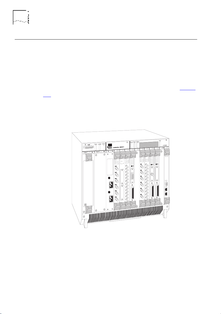
The LinkBuilder MSH is an extremely versatile chassis-based hub,
which enables you to connect and manage large,
mixed-technology, mixed-media LANs.
The basis of the LinkBuilder MSH is the chassis, into which a series
of network specific modules can be installed, as shown in Figure
1-1. The modules within the chassis connect to a backplane. It is
the backplane which allows communication between the various
LANs and LAN segments connected to the LinkBuilder MSH.
Contact your supplier for the latest list of modules available.
Figure 1-1 The LinkBuilder MSH
The LinkBuilder MSH's backplane contains three Ethernet busses.
Ethernet modules can connect to any bus or be independent of
the chassis; this is the versatility of the LinkBuilder MSH.
DUA1860-0AAA01
Page 17
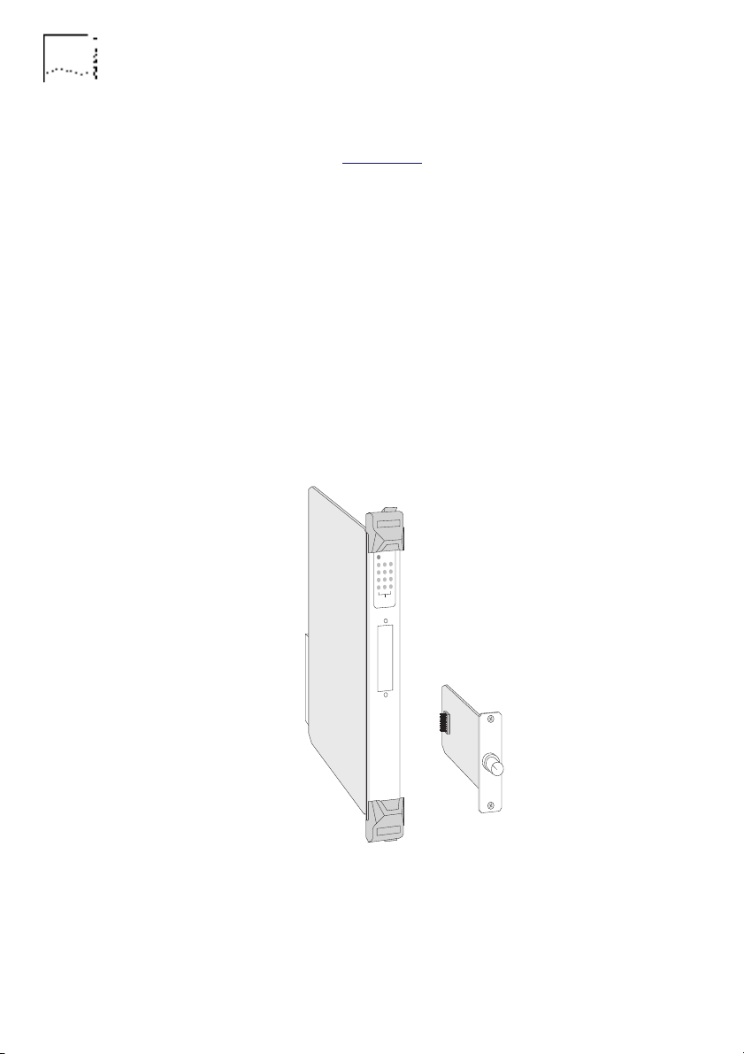
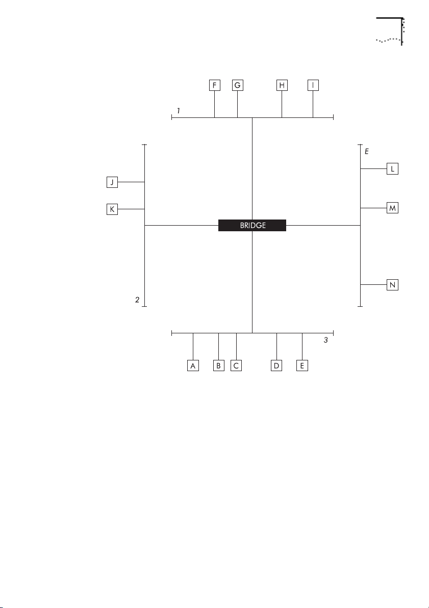
The LinkBuilder MSH 4 Port Ethernet Bridge Module 1-3
The LinkBuilder MSH 4 Port Ethernet Bridge Module
The bridge module provides a bridge connection between the
three Ethernet busses of the MSH and an external port (the bridge
module's transceiver module), as shown in Figure 1-2
bridge's connections are referred to as ports (1, 2, 3 and E).
1
2
3
. The
DUA1860-0AAA01
Figure 1-2
E
The Network Segments
Page 18

1-4 C
HAPTER
NTRODUCTION
1: I
The bridge module provides:
Connection to each Ethernet bus in the MSH.
■
An external connection by transceiver module.
■
LEDs for indicating bridge activity and diagnosing possible
■
problems.
Standard IEEE 802.1 Part D transparent bridging.
■
Additional custom bridge filtering:
■
■
Host-to-Host filtering
■
Host-to-Port filtering
■
Port-to-Port filtering
■
Multicast-to-Port filtering
■
Protocol filtering
■
Bit filtering
Spanning Tree Algorithm and Protocol (STAP).
■
DUA1860-0AAA01
Page 19
The LinkBuilder MSH 4 Port Ethernet Bridge Module 1-5
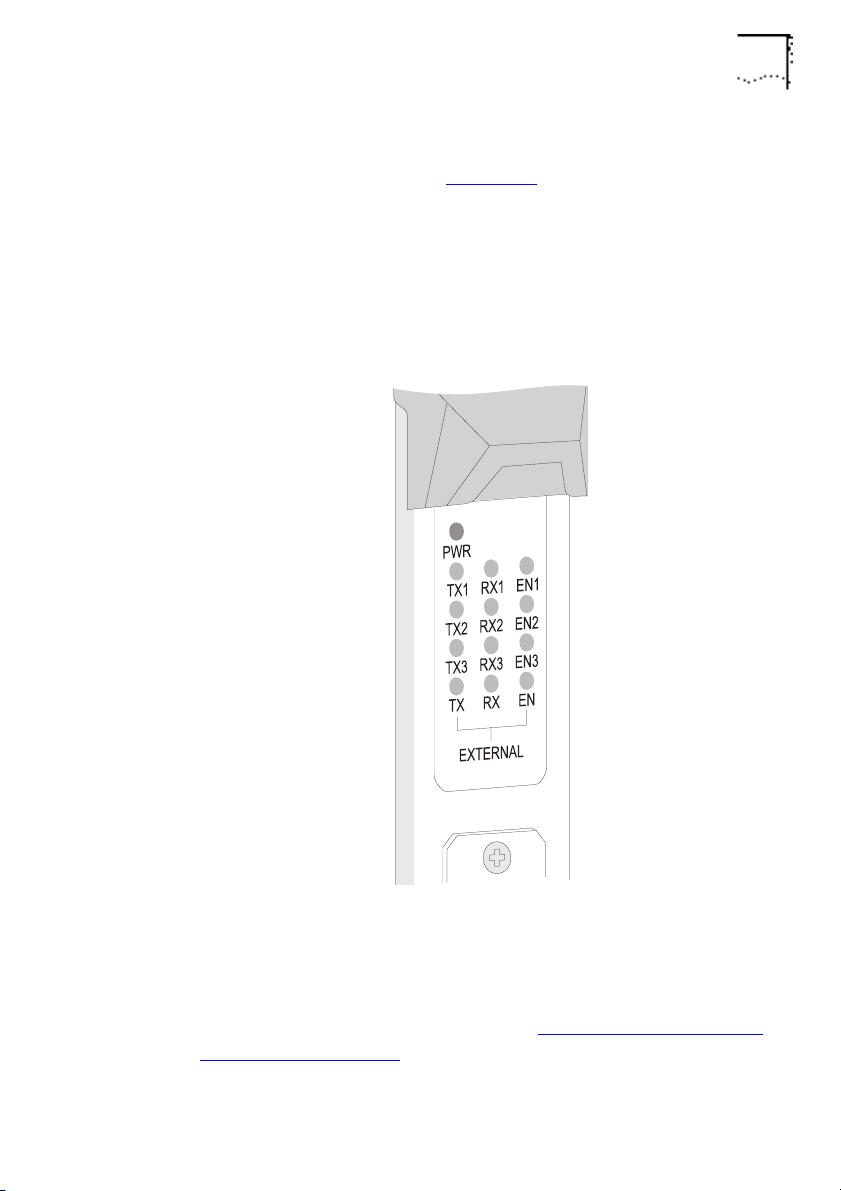
Below its top ejector, the bridge has a panel of LEDs that indicate
bridge activity, as shown in Figure 1-3
.
Each port has a row of three LEDs; transmit (TX), receive (RX) and
enabled (EN). Ports with numbers signify the Ethernet bus in the
LinkBuilder MSH chassis to which the port is connected. The
unnumbered row is for the external port, the Transceiver Module.
DUA1860-0AAA01
Figure 1-3
The Module’s LEDs
You can also use the LEDs to help with diagnosing faults on your
system, for more information refer to
Diagnosis
on page 6-3.
Using The LEDs For Fault
Page 20
1-6 C
HAPTER
NTRODUCTION
1: I
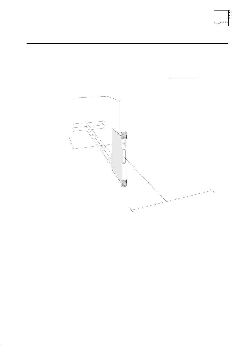
A Transceiver Module can be fitted to the bridge, providing its
fourth port, as shown in Figure 1-4
. A range of Modular
Transceivers are produced by 3Com, allowing you flexibility when
deciding on network connections and cabling:
3C12060 Female AUI Transceiver Module
■
3C12065 Fiber Transceiver Module (ST)
■
3C12064 Fan Out Transceiver Module
■
3C12066 Coaxial Transceiver Module
■
3C12060 LinkBuilder Bridge MicroModule
■
Your supplier will know of any other Transceiver Modules not
listed here.
Figure 1-4 The Transceiver Module
Instructions on how to fit a Transceiver Module are given in the
manual that accompanies it.
DUA1860-0AAA01
Page 21
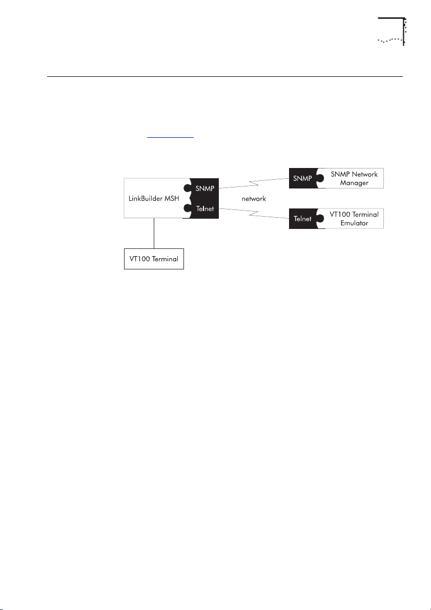
Managing The Bridge
The bridge can be managed using either the VT100 management
interface or remotely via SNMP using a suitable application, as
shown in Figure 1-5
management facilities.
Managing The Bridge 1-7
. SNMP provides a subset of the VT100
■
■
DUA1860-0AAA01
Figure 1-5
VT100 Management
To use the VT100 management interface:
Connect a VT100 terminal or VT100 terminal emulator directly to
the serial port on the display panel of the LinkBuilder MSH.
Use a VT100 terminal emulator over a network, via Telnet.
To manage the bridge, you must have a LinkBuilder MSH
Management Module (3C18500) with software version 2.1 or
later installed. If you do not have a Management Module
installed, contact your supplier.
Please refer to
The LinkBuilder MSH Management Module
manuals for information on connecting VT100.
Page 22

1-8 C
HAPTER
NTRODUCTION
1: I
Bridging
This section describes bridges and how they work.
Why Use A Bridge?
Bridges provide a way of joining two or more networks together
to form a single logical and physical network.
You can overcome various network restrictions that apply to large
individual networks by bridging smaller networks together. The
bridge remains transparent to the users of these networks.
The original networks that form the bridged network are called
network segments
devices on the network can be reached via each of its ports. It
reduces the amount of traffic on each network segment by
filtering traffic that does not need to be forwarded to it. Standard
filtering is described in
page 1-12.
. The bridge learns, from network traffic, what
Learning, Filtering And Forwarding
on
You can also apply custom filters to restrict communication
through the bridge. This allows you to add some security to your
network. Custom filtering is described in
Bridge Filters
on page
1-20.
Resilience can be built into a bridged network. The bridges on the
network can control the flow of traffic throughout the network.
Resilience is described in
on page 1-16.
(STAP)
Spanning Tree Algorithm And Protocol
DUA1860-0AAA01
Page 23
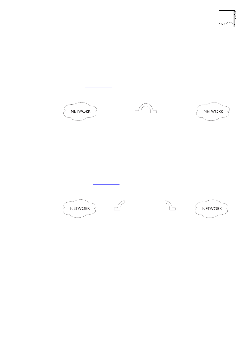
Local And Remote Bridges
Bridging 1-9
There are two main types of bridge,
local
and
remote
. The
LinkBuilder MSH 4 Port Ethernet Bridge Module is a local bridge.
Local bridges are used for bridging networks on the same site, as
shown in Figure 1-6
Figure 1-6
Local Bridge
.
Remote bridges are used for bridging networks across large areas.
A remote bridge is often called a
half
bridge because each
network connects to half of the remote bridge. The remote
bridge halves are connected by a Wide Area Network (WAN) link,
as shown in Figure 1-7
.
DUA1860-0AAA01
Figure 1-7
Remote Bridge
Both types of bridge have essentially the same operation and
functionality.
Page 24
1-10 C
HAPTER
NTRODUCTION
1: I
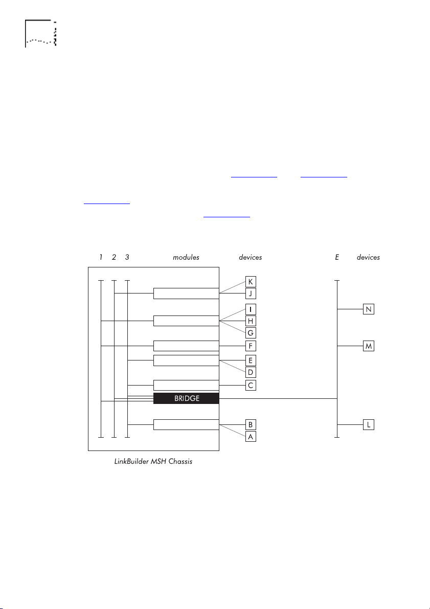
Bridge Network Topology
The
topology
of a network is essentially its layout; how its
component parts are inter-connected. The topology of your
network is dependent on the amount of bridges that you use and
the way in which you use them. If you use one 4 Port Ethernet
Bridge Module, you may have a
In the example setups shown in Figure 1-8
topology.
star
and Figure 1-9, the
bridge connects all three MSH busses and an external segment.
Figure 1-8
physically connected, and Figure 1-9
shows how the devices, modules and MSH chassis are
shows the resulting
topology.
Figure 1-8 An Example Bridge Setup
DUA1860-0AAA01
Page 25
Bridging 1-11
DUA1860-0AAA01
Figure 1-9
An Example Topology
Page 26

1-12 C
HAPTER
NTRODUCTION
1: I
Learning, Filtering And Forwarding
Transparent
bridges remain transparent to the network segments,
treating them as one overall network. The main operations of a
transparent bridge are
learning, filtering
and
forwarding
. These
operations are 802.1 bridge features and enable it to control the
flow of traffic to each network segment.
Devices send information as frames. The two main types of frame
are 802.3 and Ethernet. The destination address and source
address are contained within the frame, as shown in Figure 1-10
Destination
Address
802.3 frame
Destination
Address
Ethernet frame
Figure 1-10 Frame Contents
Source
Address
Source
Address
Length
Type
Data
Data
Frame
Checksum
Frame
Checksum
Every time the bridge receives a packet, it looks at the source
address and destination address. If the bridge has not previously
received a packet on that port from the device, it learns the
source address by adding it to a list of device addresses connected
to the port. The bridge then compares the destination address to
the address lists for all the ports on the bridge. If the destination
address appears on the address list of a port that did not receive
the packet, the bridge
forwards
(duplicates) the packet to that
port. If the destination address appears on the address list of the
same port that received the packet, the bridge
filters
(discards)
the packet. If the destination address does not appear on any of
its address lists, the bridge passes it on to all but the receiving
port, called
flooding
.
.
DUA1860-0AAA01
Page 27
Bridging 1-13
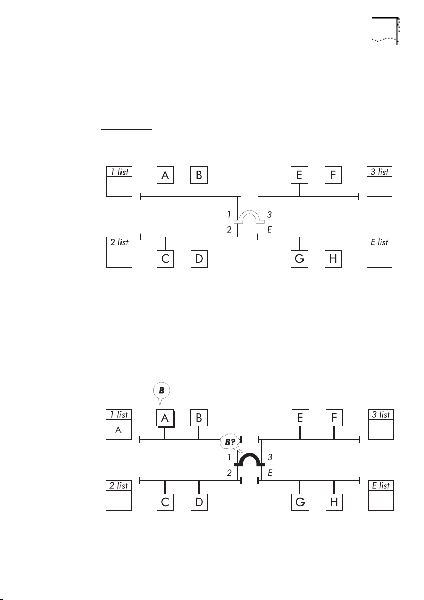
Figure 1-11, Figure 1-12, Figure 1-13 and Figure 1-14 illustrate
how a bridge learns device addresses and uses address lists to
reduce unnecessary network traffic.
Figure 1-11
: The bridge does not know what devices are on the
network.
Figure 1-11
An Example Network
Figure 1-12: Device A, connected to port 1, transmits a packet for
device B. The bridge learns the address of device A but does not
know where device B is, so it passes the packet to ports 2, 3 and
E.
DUA1860-0AAA01
Figure 1-12
Learns A, Passes On Packet
Page 28
1-14 C
HAPTER
NTRODUCTION
1: I
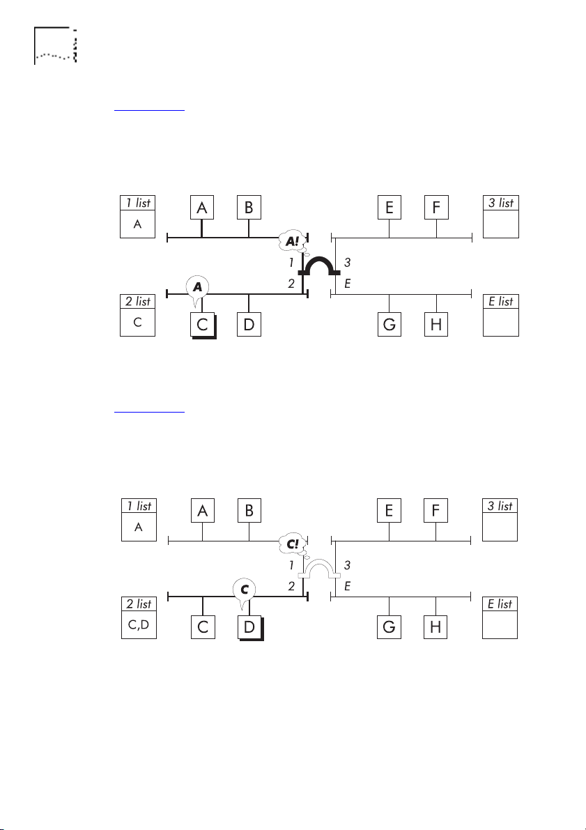
Figure 1-13: Device C, connected to port 2, transmits a packet for
device A. The bridge learns the address of device C and
recognizes the address of device A, so it forwards the packet to
port 1.
Figure 1-13 Learns C, Forwards Packet
Figure 1-14: Device D, connected to port 2, transmits a packet for
device C. The bridge learns the address of device D and
recognizes the address of device C is on the same address list, so
it filters the packet.
Figure 1-14 Learns D, Filters Packet
The bridge can now effectively control network traffic by
forwarding packets only to relevant network segments.
DUA1860-0AAA01
Page 29

Bridging 1-15
The bridge performs
ageing
on address list entries. If a port has
not received a packet from a device within a configured time (the
ageing time
), the device's address will be removed from the port's
address list. This helps the bridge to efficiently remember devices
that communicate frequently without having to cope with devices
that communicate infrequently or are no longer there.
Because the bridge continually learns new addresses and ages out
old addresses, it does not have to be reconfigured or initialized
when a device is added to the network.
DUA1860-0AAA01
Page 30
1-16 C
HAPTER
NTRODUCTION
1: I
Spanning Tree Algorithm And Protocol (STAP)
You can make your network more resilient by adding bridges and
network segments. If a network segment or bridge fails, traffic
can still travel through the network by using the additional
bridges and network segments.
The key to resilience is the number of paths through the network.
Multiple paths, however, result in
active loops
introduce redundant traffic to the network, which can quickly
degrade overall network performance and, more importantly,
breaks network rules.
. Active loops
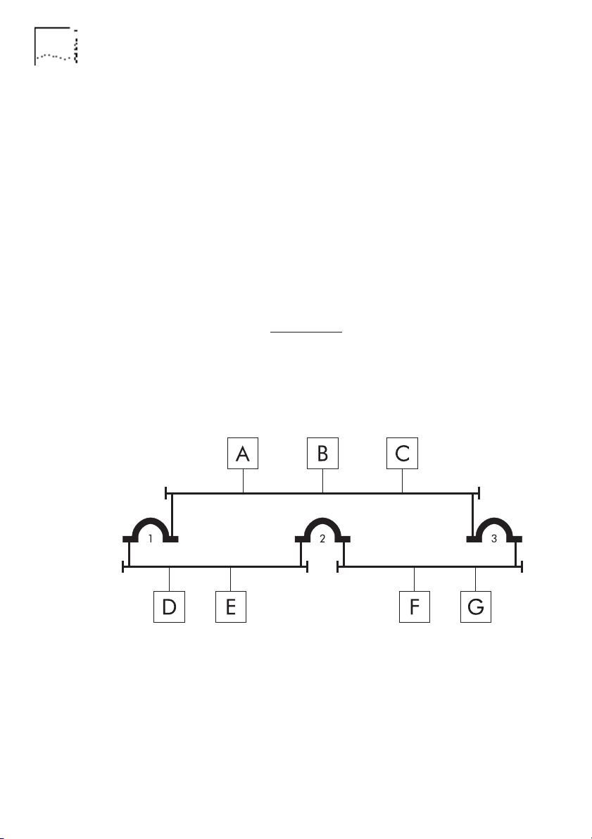
In the example shown in Figure 1-15
, three network segments are
connected by three bridges, causing an active loop. Device B
transmits a packet for device E. Bridges 1 and 3 receive the packet
and forward it. Device E receives the packet from bridge 1 but
also receives a copy from bridge 2 (via bridge 3).
Figure 1-15 An Example Active Loop
A networking standards committee of the Institute of Electronic
and Electrical Engineers (IEEE) recognized and solved the problem
by introducing the
Spanning Tree Algorithm and Protocol
(STAP).
The STAP has become a standard bridge feature.
DUA1860-0AAA01
Page 31

Bridging 1-17
In a bridged network, a
root bridge
is elected to control the other
bridges. The root bridge is made aware of any active loops by
consulting the other bridges. The STAP constructs a
spanning tree
which provides unique paths between all devices in the network,
and applies it by putting various bridges' ports in to a blocking
state, as shown in Figure 1-16
Figure 1-16
Bridge Port Blocking
.
DUA1860-0AAA01
Page 32

1-18 C
HAPTER
NTRODUCTION
1: I
The STAP is also capable of constructing a new spanning tree
should the unique path fail, see Figure 1-17
, leading to quick
network recovery.
Figure 1-17 Path Fails, Bridge Port Re-enabled
DUA1860-0AAA01
Page 33

Bridging 1-19
Network resilience obviously leads to some path redundancy, as
shown in Figure 1-18
.
DUA1860-0AAA01
Figure 1-18
Network Resilience
For more detailed STAP information, please refer to the latest
revision of the
IEEE 802.1 Part D
standard.
Page 34

1-20 C
HAPTER
1: I
Bridge Filters
The LinkBuilder MSH 4 Port Ethernet Bridge Module allows the
use of
transparent filtering, as explained in
Forwarding
filtering modes:
Host-to-Host filtering
■
Host-to-Port filtering
■
Port-to-Port filtering
■
Multicast-to-Port filtering
■
Protocol filtering
■
Bit filtering
■
This section describes these filtering modes and filtering concepts
in general.
NTRODUCTION
customised filtering
, which can be used in addition to basic
Learning, Filtering And
on page 1-12. It supports the following custom
What Is Custom Filtering?
Custom filtering
communicate through the bridge. When applied, the bridge
(discards) certain packets based on the contents of
filters
. These filter sets can be edited by the bridge operator and are
sets
used for indicating what devices' packets are to be filtered.
Figure 1-19
, Figure 1-20 and Figure 1-21 illustrate how a bridge
performs custom filtering. This particular example shows
host-to-port filtering.
lets you selectively define the hosts that can
filter
DUA1860-0AAA01
Page 35

Bridge Filters 1-21
Figure 1-19: A filter set for port 2 has been set up allowing device
A to communicate through the bridge and out of that port. No
other device can communicate through the bridge and out of that
port.
Figure 1-19
An Example Network With Filter Set
Figure 1-20: Device A transmits a packet for device C. The bridge
knows that device C is connected to port 2, so it checks that
port's filter set. Communication is allowed, so it forwards the
packet.
Figure 1-20
Forwards Packet
DUA1860-0AAA01
Page 36

1-22 C
HAPTER
NTRODUCTION
1: I
Figure 1-21: Device B transmits a packet for device C. The bridge
knows that device C is connected to port 2, so it checks that
port's filter set. Communication is not allowed, so it filters the
packet.
Figure 1-21 Filters Packet
DUA1860-0AAA01
Page 37

Filter Sets
Bridge Filters 1-23
filter set
A
is a group of devices that are allowed to communicate
with each other. The 4 Port Ethernet Bridge Module's default filter
sets let all hosts and ports communicate. If you want to restrict
communication, you must edit the default filter sets. Each custom
filter type has specific filter sets.
Host-to-Host Filtering
host-to-host
A
filter set is a group of devices that are allowed to
communicate through the bridge. There are 32 default
host-to-host filter sets for you to use. Use each filter set for a
specific group of devices, for example, if you have a set for each
department in your business, it is easier to manage your filtering.
31 host-to-host filter sets are defined as
One host-to-host filter set is defined as
inclusion
(sets 2 to 32).
absolute exclusion
(set 1).
Devices that are members of an inclusion set can only
communicate with each other through the bridge.
The absolute exclusion set is a special set used for restricting
device communication. A device that is a member of that set is
prohibited from communicating through the bridge.
he default host group ensures that no host-to-host filtering
T
takes place before the inclusion filter sets are set up.
If you set up an inclusion set, you must remove the default host
group. If you empty an inclusion set, you must replace the default
host group.
The default host group must not be added to the absolute
exclusion set.
DUA1860-0AAA01
Page 38

1-24 C
HAPTER
NTRODUCTION
1: I
Figure 1-22 illustrates a host-to-host filter example, and shows
four network segments connected by a bridge. A filter set has
been set up allowing communication between devices A and D
only, through the bridge. Every packet received by the bridge has
its source address and destination address checked. If both
addresses match the addresses in the filter sets, the packet is
forwarded.
Figure 1-22 Host-to-Host Filtering Example
Host-to-Port Filtering
Host-to-port
filters allow the user to define groups of devices that
are allowed to communicate through the bridge with devices
connected to a specific bridge port. There is a host-to-port filter
set for each bridge port.
Host-to-port filter sets can be defined as
inclusion
or
exclusion
.
Inclusion means that devices in the set can communicate out of
that port, and all other devices cannot. If the set is empty, no
devices can communicate out of that port.
DUA1860-0AAA01
Page 39

Bridge Filters 1-25
Exclusion means that devices in the set cannot communicate out
of that port, and all other devices can. If the set is empty, all
devices can communicate out of that port.
The default host group is contained in all host-to-port filter sets
following an initialization. Sets default to inclusion. The
host-to-port default host represents all hosts except those defined
in the host-to-port filter sets. If you include device A in a
host-to-port set and delete the default host, then device A will
not be able to communicate through other ports unless you also
include device A in those ports' host-to-port filter sets.
Figure 1-23
illustrates a host-to-port filter example, and shows
four network segments connected by a bridge. The ports' filter
sets have been set up, allowing device F to communicate with
devices connected to port 1, device H to communicate with
devices connected to ports 1 and 3, and device C to communicate
with devices connected to port E. Every packet received by the
bridge has its destination address checked. If the destination
addresses appears in the source address list for that port, the
packet is forwarded.
Figure 1-23
Host-to-Port Filtering Example
In the example, the bridge will forward a packet from device H to
device A. However, for the bridge to forward a packet from
device A to device H, device A's address must be added to port
E's filter set.
DUA1860-0AAA01
Page 40

1-26 C
HAPTER
NTRODUCTION
1: I
Port-to-Port Filtering
A
port-to-port
filter set is a group of ports that are allowed to
communicate through the bridge. There is a port-to-port filter set
for each bridge port.
Figure 1-24
example. Figure 1-24
and Figure 1-25 illustrate a port-to-port filter
shows four network segments connected by
a bridge. The ports' filter sets have been set up, allowing
communication between ports 1 and 2, ports 1 and E, and ports
2 and 3.
Figure 1-24 Port-to-Port Filtering Example
Figure 1-25 shows the port communications that are allowed.
Figure 1-25 Allowable Port Communication
DUA1860-0AAA01
Page 41

Bridge Filters 1-27
Changes made to port-to-port filter sets are mirrored by the other
port-to-port filter sets. For example, if ports 1 and E are added to
port 3's filter set, port 3 is automatically added to port 1's and
port E's filter sets.
Multicast-to-Port Filtering
multicast-to-port
A
filter set is a group of ports that are allowed
to send and receive broadcast and multicast packets from a
specific bridge port. There is a multicast-to-port filter set for each
bridge port.
The multicast-to-port filter sets operate in exactly the same
manner as the port-to-port filter sets, the only difference being
that multicast-to-port filter sets are used for broadcast and
multicast packets only.
Protocol Filtering
protocol
A
filter set is a group of network protocol filters for
which the bridge will permit or deny the forwarding of packets to
a specific bridge port. There is a protocol filter set for each bridge
port.
DUA1860-0AAA01
For example, if you want to prevent packets using the TCP/IP
protocol from being forwarded to the network segment
connected to port 2, you would edit port 2's protocol filter set to
deny the TCP/IP protocol.
Page 42

1-28 C
HAPTER
NTRODUCTION
1: I
Bit Filtering
Bit filters
selectively filter out traffic based on bit values occurring
in the first 64 bytes of each frame. This provides extremely flexible
filtering. You can test any combination of bits within a six-byte
long field falling within the first 64 bytes of the frame and
beginning on a byte boundary. You can have up to five input
filters and five output filters.
When you set up a bit filter, you define a
bit pattern
. The bit
pattern consists of up to 48 bit values (1 or 0), for example,
10111001. The bridge compares this pattern against the pattern
found in a specified location for every packet. If the patterns
match, the bridge filters or forwards the packet as specified by
additional filter information.
DUA1860-0AAA01
Page 43

Enabling Custom Filtering
You have to enable custom filtering before it becomes effective.
You can enable and disable all custom filters or individual custom
filters with ease.
As custom filtering can involve multiple checking of packets, it
can have an adverse impact on bridge performance in a high
traffic rate environment. Therefore, it is best to plan custom
filtering carefully, enabling filters only as necessary.
The 4 Port Ethernet Bridge Module performs filtering tests in a
specific order:
1
Multicast-to-Port filtering
2
Port-to-Port filtering
3
Host-to-Port filtering
4
Host-to-Host filtering
Bridge Filters 1-29
5
6
DUA1860-0AAA01
Protocol filtering
Bit filtering
In mathematical terms, the filtering operation is characteristic of a
logical OR. If the filter sets of any one type indicate that a packet
should be filtered out, the bridge will discard it and perform no
further tests. You can improve bridge performance by using
higher precedence filters when possible.
For example, you may set up port-to-port filter sets to filter out
packets between ports 1 and 2. You may then create a
host-to-host filter set that includes a device connected to port 1
and a device connected to port 2. These devices will not be able
to communicate because their packets will be filtered out by
port-to-port filtering.
Page 44

1-30 C
HAPTER
NTRODUCTION
1: I
Simple Network Management Protocol (SNMP)
SNMP is an application-level protocol for managing products such
as bridges on TCP/IP networks. You can issue
SNMP application. The application passes the requests to the
SNMP agent software on the device to be managed. The agent
carries out the requests and sends
responses
Requests and responses are referred to as
The SNMP agent on the bridge allows it to be managed by any
SNMP application. This agent complies with RFC 1157,
Network Management Protocol
.
The agent performs network management functions based on
GET and SET operations. These operations retrieve and store
values of variables belonging to the managed device. The
variables are defined in one or more
(MIBs).
Bases
Management Information
MIB variables are encoded in a subset of the data-description
language
rules specified by the
Abstract Syntax Notation One
Structure of Management Information
(SMI). In SMI and ASN.1 terms, a MIB contains
which has an assigned unique name, known as an
identifier
(OID).
requests
to the application.
SNMP messages
(ASN.1), according to the
objects
using an
.
A Simple
, each of
object
The names actually used in your management application to refer
to MIB variables depend entirely on that application and may be
different to OIDs.
The bridge supports the following MIBs:
Internet Standard II, as defined in RFC 1158,
■
Management
Information Base for TCP/IP-Based Internets
Internet Bridge MIB, as defined in RFC 1286,
■
Internet Ethernet MIB, as defined in RFC 1284,
■
Bridge MIB
Definitions of
Managed Objects for the Ethernet like Interface Types
DUA1860-0AAA01
Page 45

Installation And Removal
Installation And Removal 1-31
WARNING:
Please read the following safety and anti-static
information before removing the module from its anti-static
packaging.
Safety Information
To avoid having dangerous equipment:
■
Installation of this module should be carried out by qualified
personnel only.
■
This module operates under SELV conditions (Safety Extra Low
Voltage) according to IEC 950, the conditions of which are
maintained only if the equipment to which it is connected is also
operational under SELV.
■
The LinkBuilder MSH chassis must be earthed.
Anti-Static Information
To avoid damaging the module:
■
Do not remove the module from its anti-static packaging until you
are ready to install it into the LinkBuilder MSH chassis.
■
Do not touch the pins, leads, connections or any components on
the module.
■
■
■
DUA1860-0AAA01
Handle the module only by its edges.
Always wear an anti-static wristband connected to a suitable
earth point.
Always store and transport the module in anti-static packaging.
Please refer to the
MSH/11
manual for information on installing and removing the
How To Install And Use The LinkBuilder
bridge module.
Page 46

1-32 C
HAPTER
NTRODUCTION
1: I
DUA1860-0AAA01
Page 47

2
■ The VT100 Management Interface
■ The VT100 Bridge Menu Map
■ Bridge Control Keys
■ Simple Bridge Configuration
■ IP Address Configuration
■ SNMP Configuration
G
ETTING STARTED
This chapter contains the following topics:
Page 48

2-2 C
HAPTER
Introduction
This chapter describes setting up the bridge for the first time. If
you have not set up the bridge before, or are setting it up again
after initializing NVRAM, you should read this chapter.
The chapter contains the following information:
A general introduction to the VT100 Management Interface,
■
which is used to manage the bridge.
A description of how to configure a simple bridge that connects
■
up to four network segments. This configuration involves:
■
■
■
■
■
ETTING STARTED
2: G
Logging on and off the bridge
Establishing operator accounts
Defining bridge information
Saving and making changes effective
Erasing all the changes
A descrption of how to assign an IP address to the bridge so that
■
the bridge can be managed remotely via Telnet. This involves:
■
Setting up IP addresses
■
Using Telnet for remote connections
■
Using the Packet Internet Groper (PING) program to test
connections
A description of how to configure the SNMP agent on the bridge
■
so that SNMP applications can obtain information about the
bridge. This involves:
■
Configuring the basic characteristics of each community and
globally enabling or disabling the Authentication Failure Trap
■
Enabling traps for individual communities and specifying the IP
addresses where the traps should be sent
DUA1860-0AAA01
Page 49

The VT100 Management Interface 2-3
The VT100 Management Interface
The VT100 management interface is used for bridge
management. The screens are based on forms and are controlled
using special interface control keys.
The bridge has different control keys to the MSH management
module. When you log on to the bridge, the bridge control keys
take over. The bridge control keys are described in Bridge Control
Keys on page 2-8.
The screens are grouped hierarchically. For a complete menu map
of the bridge screens, see
2-6. The menu map also appears on
Ethernet Bridge Module 3C18600 Quick Reference Guide
accompanies this manual.
This chapter assumes that you are familiar with the VT100
management interface.
The VT100 Bridge Menu Map
on page
The LinkBuilder MSH 4 Port
, that
DUA1860-0AAA01
Please refer to
The LinkBuilder MSH Management Module
manual
for information on connecting VT100 and VT100 via Telnet. The
manual also describes VT100 screen conventions and VT100
control keys.
Page 50

2-4 C
HAPTER
ETTING STARTED
2: G
The VT100 Bridge Screens
The VT100 bridge screens have the same general layout. The
components of a bridge screen are shown in Figure 2-1
.
Figure 2-1 Bridge Screen Components
The components are:
A - Screen title.
The boxed words starting in the top left hand
corner of the screen.
B - Highlight.
A dark or bright bar over the input field that
receives the information you enter into the input area.
C - System name.
The name you give your bridge on the
System Information screen.
D - Local login identifier.
The name of the user currently locally
logged on to the bridge.
DUA1860-0AAA01
Page 51

The VT100 Management Interface 2-5
E - Remote login identifier.
The name of the user currently
remotely logged on to the bridge.
F - Input area.
The line below the screen area provides the data
entry location for input screens. The area starts with a short
description of the highlighted field. You enter the value in the
input area, where you can change or correct your typing as
necessary. When you press [Enter] or [Return], your input area
appears in the highlighted field. Your terminal may beep for an
inappropriate entry.
G - Prompt.
The small blinking box that shows where you are in
the input area.
H - Message area.
The line underneath the input area that
displays useful information. It usually displays the bridge's
software version and release date. If you make an error, it displays
a reason.
DUA1860-0AAA01
Page 52

2-6 C
HAPTER
ETTING STARTED
2: G
The VT100 Bridge Menu Map
The VT100 bridge menu map, as shown in Figure 2-2, shows the
links between the bridge management screens. The
at the bottom left of each screen box is the page in this manual,
where you will find the description of that screen.
italic number
Figure 2-2 The VT100 Bridge Menu Map
DUA1860-0AAA01
Page 53

The VT100 Bridge Menu Map 2-7
Operators with Administrator privileges are unrestricted.
Operators with Operator privileges cannot configure the bridge,
initialize NVRAM, or reset the bridge (the Administrative Screens).
DUA1860-0AAA01
Page 54

2-8 C
HAPTER
ETTING STARTED
2: G
Bridge Control Keys
There are special control keys for operating the bridge. These are
different to the MSH management module control keys and
should be used from the time you log on to the bridge. For [Ctrl]
key sequences, hold down the [Ctrl] key while pressing the
specified key. For [Esc] key sequences, press [Esc] and then press
the specified key.
The bridge control keys are described in Table 2-1
Table 2-1 Bridge Control Keys
Key Description
Help
[?] [Esc] [H] Displays a help screen. Many screens have their own
Quick keys
letters Selects the menu item preceded by the character.
Select or confirm entry
[Return] [Enter] Selects the current menu item or confirms the entry
Previous screen
[Ctrl] + [Z]
[Esc] [P]
:
help screens. The general help screen appears for
screens without specific help screens.
You do not need to press [Return]. For example, [B]
will take you from the Main Menu to the
Configuration menu. [B] [A] [A] will take you from
the Main Menu to the System Information screen.
for a field and moves to the next entry field.
Returns you to the previous screen or menu.
DUA1860-0AAA01
Page 55

Bridge Control Keys 2-9
Table 2-1
Bridge Control Keys
Key Description
Return to Main Menu
[Ctrl] + [T]
Returns you to the Main Menu.
[Ctrl] + [C]
[Ctrl] + [Y]
[Esc] [T]
Return to MSH Management Module
[Ctrl] + [P] When logged on locally, this returns you to the MSH
Management Module screens. We recommend you
log off the bridge before entering this command.
Move up
[Up Arrow] Selects the previous menu item or highlights the
previous entry field.
Move down
[Down Arrow] Selects the next menu item or highlights the next
entry field.
Move left
[Left Arrow] Moves the cursor left one character in the entry field.
DUA1860-0AAA01
Move right
[Right Arrow] Moves the cursor right one character in the entry
field.
Delete character
[Backspace]
[Delete]
[Ctrl] + [D]
Deletes the character to the left of the cursor in the
entry field. [Ctrl] + [D] has a different use when the
extended bridge control keys are in use.
Delete all
[Ctrl] + [U] Delete all the input in the entry field.
Page 56

2-10 C
HAPTER
ETTING STARTED
2: G
Table 2-1 Bridge Control Keys
Key Description
Refresh screen
[Ctrl] + [V]
[Esc] [V]
Next step
[Esc] [N] Takes you to the next menu or screen, or returns you
Interrupt Telnet
[Break] Interrupts a Telnet connection without waiting for it
Resume serial communication
[Ctrl] + [Q] Resumes serial communication if accidentally turned
Refreshes the screen.
from help. Using this from a menu, takes you to the
screen associated with the highlighted item.
to time out.
off (XOFF).
DUA1860-0AAA01
Page 57

Simple Bridge Configuration
This section describes how to configure a simple bridge that
connects up to four network segments.
Ensure all bridge connections are in place before you start.
Initially, the bridge has no IP address. Without a unique IP address,
it cannot be remotely managed, so you must first log on to the
LinkBuilder MSH, then log on to the bridge, then set up a unique
IP address.
This simple configuration describes:
■
Logging on and off the bridge
■
Establishing operator accounts
■
Defining bridge information
■
Saving and making changes effective
Simple Bridge Configuration 2-11
■
DUA1860-0AAA01
Erasing all configurations
You will need to configure the bridge for your particular
installation. Write down all the changes that you make, so you
have a configuration record. We recommend that before
configuration, you look at the different bridge screens to
understand how they are linked and what information they
require.
Most screens have their own help screen. If a screen does not
have one, the general help screen is displayed.
Page 58

2-12 C
HAPTER
ETTING STARTED
2: G
Logging On To The LinkBuilder MSH
Logging on to the LinkBuilder MSH is also described in
LinkBuilder MSH Management Module
manual.
The
Connect to the LinkBuilder MSH. The Main Banner appears, as
shown in Figure 2-3
.
Press [Enter] to continue.
Figure 2-3 LinkBuilder MSH Main Banner
DUA1860-0AAA01
Page 59

Simple Bridge Configuration 2-13
The Logon screen appears and stays displayed until a valid User
Name and Password have been entered, as shown in Figure 2-4
Enter a User Name and Password for the LinkBuilder MSH.
.
DUA1860-0AAA01
Figure 2-4
LinkBuilder MSH Logon Screen
Page 60

2-14 C
HAPTER
ETTING STARTED
2: G
When you are logged on to the LinkBuilder MSH, the Main Menu
appears, as shown in Figure 2-5
. It offers various LinkBuilder MSH
management options. The LOGOFF option closes down the
session, allowing the interface to ‘sleep’.
Select SERVICE SELECTION.
Figure 2-5 LinkBuilder MSH Main Menu
DUA1860-0AAA01
Page 61

Simple Bridge Configuration 2-15
The Service Selection screen appears, listing all the services within
the LinkBuilder MSH Chassis with the number of the slot or
backplane to which it is attached, as shown in Figure 2-6
Highlight 4 PORT .3 BRIDGE, press [Space] and select
.
OK
to select
the LinkBuilder MSH 4 Port Ethernet Bridge Module.
DUA1860-0AAA01
Figure 2-6
LinkBuilder MSH Service Selection
If the 4 Port Ethernet Bridge Module does not appear, either the
module is self-testing, has been incorrectly installed, or the MSH
management agent software is not version 2.1 or later.
Page 62

2-16 C
HAPTER
ETTING STARTED
2: G
The Address Table screen appears, showing default address
information for the bridge, as shown in Figure 2-7
. If the bridge's
IP address is unconfigured, a random IP address is shown.
Select MANAGE to continue.
Figure 2-7 LinkBuilder MSH Address Table
DUA1860-0AAA01
Page 63

Logging On To The Bridge
When you connect to the bridge, the Operator Login screen
appears, as shown in Figure 2-8
has no Operator IDs or Passwords, meaning that the bridge has
no security. You must set up an administrator account before any
security becomes active. This configuration includes this set up.
If no accounts have been set up, press [Enter] for both fields.
If you have an account with administrative privileges, enter the
Operator ID and Password. If you have accounts with
administrative privileges but have forgotten the Operator IDs and
Passwords, you may have to reset the bridge's configuration to
default values, see Appendix A.
Simple Bridge Configuration 2-17
. Until it is configured, the bridge
DUA1860-0AAA01
Figure 2-8
Operator ID:
Operator Login
Text Field. The operator ID is a string of one to
eight alpha-numeric characters and is case sensitive.
Password:
Text Field. The password is a string of one to eight
alpha-numeric characters and is case sensitive. One
for each character typed.
X
will appear
Page 64

2-18 C
HAPTER
ETTING STARTED
2: G
Establishing Operator Accounts
When you have logged on to the bridge, the bridge's Main Menu
appears, offering various management options, as shown in
Figure 2-9
.
The bridge's security is disabled if no administrative operator
accounts have been set up, so you should set up these accounts
first.
Select CONFIGURATION.
Figure 2-9 Main Menu
DUA1860-0AAA01
Page 65

Simple Bridge Configuration 2-19
The Configuration menu appears, as shown in Figure 2-10. You
can access all the configuration screens and sub-menus from this
menu.
Select SYSTEM.
DUA1860-0AAA01
Figure 2-10
Configuration Menu
The System menu appears.
Select OPERATOR ACCOUNTS from the System menu.
Page 66

2-20 C
HAPTER
ETTING STARTED
2: G
The Operator Accounts screen appears, listing the operator
accounts that are set up for the bridge, see Figure 2-11. You can
set up 60 operator accounts for the bridge.
Enter the number of the operator account you want to set up.
Figure 2-11 Operator Accounts
Display Field. The account numbers of the 60 accounts.
No:
Account:
Display Field. The operator ID for the account. This can
be changed with the Edit User Accounts screen that follows on
from this screen. Blank entries indicate that the account has not
been assigned.
Display Field. The designated privilege for the account.
Priv:
for administrator and
is for operator. Accounts with operator
O
is
A
privilege cannot configure the bridge, initialize NVRAM, or reset
the bridge.
Security checking is disabled if no operators are allocated
administrator privileges. This prevents a lock out from
configuration areas.
DUA1860-0AAA01
Page 67

Simple Bridge Configuration 2-21
Account Number:
Text Field. Enter the account number of the
operator you want to set up. You can set up from 1 to 60
accounts. After entering an account number, the Edit User
Accounts screen appears.
DUA1860-0AAA01
Page 68

2-22 C
HAPTER
ETTING STARTED
2: G
The Edit User Accounts screen appears with information on the
operator account you entered in the Operator Accounts screen, as
shown in Figure 2-12
. You use this screen for entering and
modifying operator account information. Any existing
information is displayed.
Set up operator accounts by entering an Operator ID, Operator
Privilege and Password (repeat the Password for verification). To
set up a different operator account, enter its Account Number.
When you have finished, return to the System menu.
Figure 2-12 Edit User Accounts
Account Number:
Text Field. The number of the operator
account. To configure a different account, enter its account
number and the Edit User Accounts screen changes to display this
account's information. This saves having to return to the Operator
Accounts screen. The account number can be from 1 to 60.
Operator ID
Text Field. The operator's ID is a string of one to
:
eight alpha-numeric characters. When entered elsewhere, the
operator ID is case sensitive. Changes to this field are only saved
during a bridge reset, and take effect from then on.
DUA1860-0AAA01
Page 69

Simple Bridge Configuration 2-23
Operator Privilege:
for the operator.
A
is for administrator and O is for operator.
Choice Field (
A
/ O). Designate the privileges
Bridge operators can be set up with either Administrator or
Operator privileges. Operators with Administrator privileges are
unrestricted. Operators with Operator privileges cannot configure
the bridge, initialize NVRAM, or reset the bridge.
Security checking remains disabled if no operators are allocated
administrator privileges. This prevents a lock out from
administrative areas.
Changes to this field are only saved during a bridge reset, and
take effect from then on.
Password:
Text Field. The password is a string of one to eight
alpha-numeric characters. When entered elsewhere, the
password is case sensitive. One
X
will appear for each character
typed. Changes to this field are only saved during a bridge reset,
and take effect from then on.
DUA1860-0AAA01
Page 70

2-24 C
HAPTER
ETTING STARTED
2: G
Adding Bridge Information
You should provide general device information for your bridge the
first time you set it up. This information is required by all MIB II
conformant devices and is generally useful because it includes the
location of the bridge and the name of the person responsible for
it (useful if the bridge is not operating correctly).
Select SYSTEM INFORMATION from the System menu.
The System Information screen appears, as shown in Figure 2-13
You use this screen for entering and modifying device
information. Any existing information is displayed.
Enter the information and, when you are sure it is correct, return
to the Configuration menu.
Figure 2-13 System Information
System Name:
Text Field. Enter a name for the bridge. This is a
string of 1 to 16 characters. Changes to this field are only saved
during a bridge reset, and take effect from then on.
.
DUA1860-0AAA01
Page 71

Simple Bridge Configuration 2-25
System Contact:
Text Field. Enter the name of the person who is
responsible for the bridge. This is a string of 1 to 16 characters.
Changes to this field are only saved during a bridge reset, and
take effect from then on.
System Location:
Text Field. Enter the physical location of the
bridge. This helps if ever it needs to be located. This is a string of
1 to 16 characters. Changes to this field are only saved during a
bridge reset, and take effect from then on.
Local Time/Date:
Text Field. Enter the local time and date.
Changes to this field are only saved during a bridge reset, and
take effect from then on.
Local Control Terminal Port Mode:
be set to
standard
. Do not change this field.
Remote Control Terminal Port Mode:
should be set to
Bridge Statistics Averaging:
standard
. Do not change this field.
Tex t F ie ld (
Text Field. This field should
Text Field. This field
on
off
/
). Set the
method by which statistics are displayed on the Bridge Statistics
and Bridge Port Statistics monitoring screens. If you want the
accumulated statistics averaged per second, specify
on
. If you
want the total accumulated statistics (since power up), specify
off
.
DUA1860-0AAA01
Page 72

2-26 C
HAPTER
ETTING STARTED
2: G
Saving And Making Changes Effective
Some of the changes you can make to the bridge are not saved if
you simply log off. However, not all fields require a bridge reset to
save them and make them effective. The field descriptions that
accompany each screen, in this manual, describe the necessary
procedures.
Any changes that are saved, are saved in NVRAM (Non Volatile
Random Access Memory). Changes in NVRAM are remembered
over a power cycle.
Select BRIDGE RESET from the Configuration menu.
The Bridge Reset screen appears, as shown in Figure 2-14
. It
reminds you of its effect and prompts you for a yes/no answer.
Enter
to reset the bridge or no to return to the Configuration
yes
menu.
Figure 2-14 Bridge Reset
DUA1860-0AAA01
Page 73

Erasing All Changes
If you want to erase all the changes made to the bridge since
logging on, simply log off the bridge. However, if you want to
erase all the changes ever made to the bridge, you must initialize
NVRAM (Non Volatile Random Access Memory) and reset the
bridge. If you initialize NVRAM but do not reset the bridge,
logging off instead, the changes will not be erased.
Select INITIALIZE NOVRAM from the Configuration menu.
Simple Bridge Configuration 2-27
The Initialize NOVRAM screen appears, as shown in Figure 2-15
warns you of its effect and prompts you for a yes/no answer.
yes
Enter
to agree to initializing NVRAM or no to return to the
Configuration menu.
If you enter
yes
, the Reset Bridge screen appears. This screen
warns you of its effect and prompts you for a yes/no answer.
yes
Enter
to initialize NVRAM or no to return to the
Configuration menu.
. It
DUA1860-0AAA01
Figure 2-15
Initialize NVRAM
Page 74

2-28 C
HAPTER
ETTING STARTED
2: G
Logging Off The Bridge
Selecting LOGOUT from the Main Menu will log you off the
bridge and return you to the display you had before logging on.
Any changes that have been made since logging on will be
erased. Most fields, but not all, require a bridge reset to save
them and make them effective, see
Effective
on page 2-26.
We recommend that you log off the bridge before returning to
the MSH Management Module screens.
Saving And Making Changes
DUA1860-0AAA01
Page 75

IP Address Configuration
This section describes how to assign an IP address to the bridge.
When the bridge has an IP address, you can remotely manage it
via Telnet, and will not need to go through the LinkBuilder MSH.
Telnet is a TCP/IP application. SNMP also requires the bridge to
have an IP address.
This simple configuration describes:
■
Setting up IP addresses
■
Using Telnet for remote connections
■
Using PING to test connections
Every IP network device is identifiable by its unique IP address
(Internet Protocol address). An extension to the IP addressing
scheme allows you to divide networks into subnetworks. The
subnet mask identifies which parts of the IP address denote the
network (network number) and which denote the host (host
number).
IP Address Configuration 2-29
DUA1860-0AAA01
IP devices can only communicate with devices on different
networks via IP routers (gateways). A subnet mask is not needed
unless the network is IP routed.
If you have a private IP network, you can assign any IP address
you like. However, if you are connecting to the Internet, your IP
address must be unique. Network numbers can be assigned by
the Network Information Center (NIC). This organization assigns a
globally unique network number to each network that wishes to
connect to the Internet. The host numbers are then assigned by
your local system administration.
Page 76

2-30 C
HAPTER
ETTING STARTED
2: G
Bridge Connections
The Telnet protocol is used for remotely logging on to a device.
The following requirements must be met for remote login:
You must have an account on the host and you must know the
■
operator ID and password for that account.
You must know either the host name or IP address of the host.
■
You can only use the host names configured in your local IP Host
Table screen.
If you are logging on from a remote host, the terminal must
■
support VT100.
Logging On To The Bridge
You can log on to the bridge locally (via the LinkBuilder MSH) and
remotely (via Telnet). The bridge can accept:
Either a local or a remote log on.
■
Both a local and a remote log on.
■
The bridge cannot accept:
Multiple local or remote log ons.
■
Telnet From The Bridge
The bridge has Telnet capabilities, allowing you to Telnet from the
bridge to another device. The bridge allows you to:
Telnet from the bridge if you have locally logged on. The bridge
■
can still accept a remote log on.
The bridge does not allow you to:
Have multiple Telnet sessions from the bridge.
■
Telnet from the bridge if you have remotely logged on.
■
DUA1860-0AAA01
Page 77

Setting Up Remote Access
Initially, the bridge has no IP addressing information. When set
up, the IP address identifies the bridge. The IP Addresses screen is
used for setting up an IP address for the bridge so that other
devices can communicate with its management agent.
Select CONFIGURATION from the Main Menu. Select NETWORK
PROTOCOL from the Configuration menu. Select IP ADDRESSES
from the Network Protocol menu.
The IP Addresses screen appears, displaying two tables, Active
and Next Reset, as shown in Figure 2-16
the IP Address and Subnet Mask that are currently used. The Next
Reset table allows you to enter a new IP Address and Subnet
Mask, which will be used after the bridge is next reset. Highlight
the field you wish to change and an area for entering the new
information will appear at the bottom of the screen.
Enter your address information. A Subnet Mask is not needed
unless the network is IP routed. After entering your information,
the IP Address screen asks if you want to reset the bridge. Ignore
this and reset the bridge when you've completed this section.
IP Address Configuration 2-31
. The Active table shows
DUA1860-0AAA01
Figure 2-16
IP Addresses
Page 78

2-32 C
HAPTER
Active
ETTING STARTED
2: G
IP Address:
Display Field. The bridge's current IP address. A line
of dashes indicates that no IP address has been assigned to the
bridge.
Subnet Mask:
Display Field. The bridge's current subnet mask.
Next Reset
IP Address:
Text Field. Enter the IP address you want to assign to
the bridge. It must be unique and of the form nnn.nnn.nnn.nnn
(decimal). Enter
0.0.0.0
to remove the bridge's IP address.
Changes to this field are only saved during a bridge reset, and
take effect from then on.
Subnet Mask:
Text Field. Enter the subnet mask you want to
assign to the bridge. A subnet mask is not needed unless the
network is IP routed. It must be of the form nnn.nnn.nnn.nnn
(decimal). Changes to this field are only saved during a bridge
reset, and take effect from then on.
DUA1860-0AAA01
Page 79

IP Address Configuration 2-33
Static Routes
If you are using a routed network, you will need to enter a default
gateway to ensure remote communication with the bridge. A
more resilient network can be set up by defining a set of
routes
. Static routes are predefined routes, with different levels of
static
priority, through the routed network. The highest priority route
will be used until a router or cable goes down, breaking the
route. When this happens, the next priority route is used.
Select IP STATIC ROUTES from the Network Protocol menu.
The Static Routes screen appears, as shown in Figure 2-17
. You
use this table to specify gateways the IP router should use to
reach specific network, host or subnet destinations.
Each static route includes a preference value. If protocols are
enabled, the preference you specify in a static route to a network
or subnet destination is compared to preference values for the
same destination learned through protocol messages from the
network. If the static route preference value is higher (less
desirable) than a route learned over the network, the static route
is replaced. However, since the protocols deal only with network
(or subnet) destinations, enabling them does not change any
static routes that you specify for hosts.
DUA1860-0AAA01
Figure 2-17
Static Routes
Page 80

2-34 C
HAPTER
ETTING STARTED
2: G
Item:
Text Field. The number of a configured static route or
0
(to
enter a new route). Static routes are sorted by IP address and
assigned numbers according to their positions in the sorted list.
Entering the number of a configured static route causes that
route to be displayed.
Destination Host:
Text Field. The IP address of a network, host,
or gateway, or a [Space] character, or the keyword default.
Specify the address in decimal notation, nnn.nnn.nnn.nnn. If a
host name has been defined in the IP Host Table screen, you can
use that name rather than the IP address.
The IP address can be an address that is configured in a static
route, or an address for a new route. If the address is already
configured, entering it causes its parameters to be displayed on
the line you can edit. If it is not configured, the remaining fields in
the line are blank.
A [Space] character deletes the route displayed. Item numbers are
adjusted accordingly.
default
is equivalent to the address
0.0.0.0
, which is the
destination for the default gateway. In other words, the gateway
you specify for this destination is the one that will be used for any
route not defined in the routing table.
Enter
for the SAVE CHANGES? field to save changes to this
y
field. Changes only take effect after a bridge reset.
Gateway:
Text Field. The IP address or host name of the gateway
that is the next hop for the destination host specified in the
previous field. If a host name is given, it must be defined in the IP
Host Table screen. Enter
for the SAVE CHANGES? field to save
y
changes to this field. Changes only take effect after a bridge
reset.
DUA1860-0AAA01
Page 81

IP Address Configuration 2-35
Preference:
Text Field. A whole number from 0 to 255,
designating the rank to be assigned to the route specified by the
DESTINATION HOST and GATEWAY fields.
255
desirable route,
default is
50
. Enter y for the SAVE CHANGES? field to save
represents the least desirable route. The
0
represents the most
changes to this field. Changes only take effect after a bridge
reset.
Save changes?:
Text Field. Enter
this screen to NVRAM, or
n
to not save any changes. Changes
y
to save any changes made to
only take effect after a bridge reset.
DUA1860-0AAA01
Page 82

2-36 C
HAPTER
ETTING STARTED
2: G
Assigning Host Name / IP Address Pairs
You can assign symbolic names (
host names
) for devices that can
communicate with or from the bridge. If a device has an IP
address, a host name can be assigned to it. This host name can
then be used instead of the IP address to identify the device,
when using the bridge. It is not necessary to assign host names,
but they are a lot easier to remember than IP addresses. The IP
Host Table screen is used for assigning IP address / host name
pairs and is primarily used for Telnet.
Select HOST TABLE from the Network Protocol menu.
The IP Host Table screen appears, displaying two tables, IP
Addresses and Host Name, as shown in Figure 2-18
. The Host
Name table lists the existing host names assigned to the
corresponding IP address in the IP Addresses table.
Enter IP address / host name pairs for devices that can access the
bridge. The host name must be unique for each device. For a
bridge, use the name defined in its System Information screen as
its host name.
Figure 2-18 IP Host Table
DUA1860-0AAA01
Page 83

IP Address Configuration 2-37
IP Address:
Text Field. Enter the IP address for the device. It must
be in decimal and of the form nnn.nnn.nnn.nnn. Changes to this
field are only saved during a bridge reset, and take effect from
then on.
Host Name:
Text Field. Enter the host name for the device.
Changes to this field are only saved during a bridge reset, and
take effect from then on.
The IP Host Table screen is updated with any new IP address / host
name pairs that are entered in the custom filtering screens.
DUA1860-0AAA01
Page 84

2-38 C
HAPTER
ETTING STARTED
2: G
Using PING To Test Connections
The PING (Packet InterNet Groper) program checks for a valid
connection to a network device. Any device with an IP address
can respond to a PING session. It tests network connections by
sending packets to a specified IP address and checking the
response.
If you have just set up address information for the bridge, reset
the bridge to save the information and for it to take effect.
We recommend that you PING the LinkBuilder MSH Management
Module, in the same chassis as the bridge, to test that PING is
working correctly.
You could use PING if:
You can't connect to a remote device and are unsure if it is
■
working.
There is a problem on the network and you need to check all the
■
nodes for response quickly.
If you get no response from a device, it could be because:
You are using the wrong IP address.
■
No one has assigned the IP address to the remote device or, if a
■
host name was used, the host name is not assigned to that IP
address in the bridge's host table. You may wish to contact
someone at the remote site.
The host is shut off or has crashed. You may wish to contact
■
someone at the remote site.
Your subnet mask is wrong.
■
The default gateway is wrong.
■
You have not assigned an IP address to the bridge.
■
DUA1860-0AAA01
Page 85

IP Address Configuration 2-39
Select PING from the Applications menu.
The Ping Settings screen appears, as shown in Figure 2-19
. Enter
the IP address or host name of the remote device and confirm the
packet size and timeout parameters (modify these only if
necessary).
Figure 2-19
Destination IP address:
Ping Settings
Text Field. Enter the IP address for the
remote device. It must be in decimal and of the form
nnn.nnn.nnn.nnn.
DUA1860-0AAA01
or
Enter the host name for the remote device. This host name must
be in the host table of your bridge.
Packet Size:
Text Field. The number of bytes in the packet,
excluding the header, that contains the echo request message.
Timeout:
Text Field. The number of seconds PING waits for an
ICMP echo response message, before giving up and sending the
next ICMP echo request message.
Page 86

2-40 C
HAPTER
ETTING STARTED
2: G
The Ping screen appears, as shown in Figure 2-20, after the
information for the Ping Settings screen has been supplied. The
Ping screen immediately starts displaying status messages when
information is received.
When you've finished with the Ping screen, press [Enter] or
[Return] to exit from it.
Figure 2-20 Ping
Destination:
Display Field. The IP address or host name of the
remote device being pinged.
Packet Size:
Display Field. The number of bytes in the packet,
excluding the header, that contains the echo request message.
Timeout:
Display Field. The number of seconds PING waits for an
ICMP echo response message, before giving up and sending the
next ICMP echo request message.
Packets Sent:
Display Field. The number of ICMP echo request
messages that have been sent to the destination address.
DUA1860-0AAA01
Page 87

IP Address Configuration 2-41
Packets Received:
Display Field. The number of ICMP echo
response messages that have been received from the destination
address.
Minimum:
Display Field. The shortest amount of time (in
milliseconds) that elapsed between sending an ICMP echo request
and receiving an ICMP echo response.
Average:
Display Field. The average amount of time (in
milliseconds) that elapsed between sending an ICMP echo request
and receiving an ICMP echo response.
Maximum:
Display Field. The longest amount of time (in
milliseconds) that elapsed between sending an ICMP echo request
and receiving an ICMP echo response.
DUA1860-0AAA01
Page 88

2-42 C
HAPTER
ETTING STARTED
2: G
Telnet Log On To Another IP Device From The Bridge
The bridge has Telnet capabilities, allowing you to remotely log on
to an IP device. This is especially useful for logging on to other
LinkBuilder MSH 4 Port Bridge Modules. However, the bridge
does not always allow you to Telnet out. For information on when
you can Telnet, see
Bridge Connections
on page 2-30. You may
wish to Telnet to the LinkBuilder MSH Management Module.
Select APPLICATIONS from the Main Menu. Select TELNET from
the Applications menu, to start a Telnet session.
One of the following will happen:
If the Connections menu appears, the bridge has already
■
accepted a remote log on. You are not allowed to Telnet out from
the bridge.
If you are remotely logged on to the bridge, you can talk to a local
user (the user who has logged on to the bridge locally), if present,
by using the Chat screen (select CHAT W. LOCAL to display this
screen). When you have finished, select END CONNECTION.
If you are locally logged on to the bridge, you can talk to a remote
user (the user who has logged on to the bridge remotely), if
present, by using the Chat screen (select CHAT W. REMOTE to
display this screen). When you have finished, select END
CONNECTION.
DUA1860-0AAA01
Page 89

IP Address Configuration 2-43
■
If the Remote Connect screen appears, as shown in Figure 2-21,
you are allowed to Telnet out from the bridge. Enter the host
name or IP address of the device you want to log on to. If you use
a host name, it must appear in the bridge's host table. If you use
an IP address, it must be in the decimal form nnn.nnn.nnn.nnn.
DUA1860-0AAA01
Figure 2-21
Remote Connect
Page 90

2-44 C
HAPTER
ETTING STARTED
2: G
Talking To Another Bridge User
The bridge can accept two users, one local and one remote. If
both users are present, they can exchange messages via the Chat
screen.
The Chat screen, as shown in Figure 2-22
, is intended for
exchanging uncomplicated information:
Warning the other user that you are about to reset the bridge or
■
change its configuration.
Exchanging telephone numbers so you can discuss any network
■
issues you may have.
The local user can get the Chat screen by selecting CHAT W.
REMOTE from the Connections menu. The remote user can get
the Chat screen by selecting CHAT W. LOCAL from the
Connections menu.
Figure 2-22 Chat
Message:
Text Field. Enter your message for the other user. It
can be up to 50 characters long.
DUA1860-0AAA01
Page 91

IP Address Configuration 2-45
Telnet Suspension
You can suspend your Telnet session from the bridge at any time.
You may want to do this if you want to return to the bridge but
stay connected to the remote device.
To suspend a remote session, press [Ctrl] + [ ] ]. You will be
returned to the Main Menu of the bridge. To resume a suspended
session, press [Ctrl] + [ ] ] again.
Tel ne t L og Off
To disconnect from the remote device, select END CONNECTION
from the Connections menu. The Terminate Connection screen
appears, displaying the IP address and host name of the remote
host you wish to disconnect from, as shown in Figure 2-23
.
If you want to disconnect from the remote device, press [Enter] or
[Return]. If you do not want to disconnect from the remote
device, leave the screen.
DUA1860-0AAA01
Figure 2-23
Terminate Connection
Page 92

2-46 C
HAPTER
ETTING STARTED
2: G
SNMP Configuration
This section describes configuration of the
bridge. When the SNMP agent has been configured, SNMP
applications can obtain information from it about the bridge.
This section describes how to:
Configure the basic characteristics of each community and
■
globally enable or disable the Authentication Failure trap.
Enable traps for individual communities and specify the IP
■
addresses to which the traps should be sent.
The basic concepts of SNMP are explained in
Algorithm And Protocol (STAP)
Remember to reset the bridge after setting up the SNMP agent if
you want your configuration to be saved and take effect.
Community Administration
The bridge has a
community
administrative relationship between a
SNMP agent it wishes to communicate with.
On the bridge, for the community you must configure:
SNMP agent
Spanning Tree
on page 1-16.
. A community defines an
(a device) and the
client
on the
A
community name
■
used by the client and agent as a password
for communicating with each other and included in all messages
exchanged between them.
■
A
MIB view
defining the subset of MIB variables that can be
accessed by client requests containing the community name.
An
■
access mode
specifying whether client requests containing the
community name can perform read only (GET) operations, or read
and write (GET and SET) operations on MIB variables.
DUA1860-0AAA01
Page 93

Traps
SNMP Configuration 2-47
An SNMP agent can send messages,
traps
, when exceptional
events occur. Traps include the name of the community involved
in the event. They are sent to an IP address that you define for
each community during configuration of the agent.
The main advantage of traps is that you do not have to constantly
monitor the bridge because it alerts you when any exceptional
events occur.
The bridge's SNMP agent supports the following bridge traps:
■
Authentication Failure
An SNMP client has tried to access the agent using a community
name the agent does not recognize, or requesting an action not
allowed for the community.
■
Cold Start
The agent is initializing itself. The values of MIB variables may
change.
■
Interface Up
A port, previously not operational, is now operational.
■
Interface Down
■
■
DUA1860-0AAA01
A port, previously operational, is now not operational.
New Root
The bridge on which the agent is running has become the new
root of the Spanning Tree.
Topology Change
One of the configured bridge's configured ports has gone into or
out of the Forwarding state. This could be due to STAP or manual
configuration.
Page 94

2-48 C
HAPTER
ETTING STARTED
2: G
Configuring Basic Community Characteristics
Select CONFIGURATION from the Main Menu and then
NETWORK PROTOCOL from the Configuration menu. Select
SNMP from the Network Protocol menu to get the Configure
SNMP menu.
Select COMMUNITIES from the Configure SNMP menu.
The SNMP Community Basic Configuration screen appears, as
shown in Figure 2-24
. You use this screen for enabling or
disabling the authentication trap for the SNMP agent running on
the bridge. You would also use this screen for configuring the
community name, MIB view, and SNMP access mode for the
community that will access the SNMP agent.
Figure 2-24 SNMP Community Basic Configuration
DUA1860-0AAA01
Page 95

SNMP Configuration 2-49
Authentication Failure Trap:
Text Field (
the authentication failure trap for the SNMP agent. Enter
enable, or enter
d
to disable. The default is disable.
e
/ d). Enable or disable
e
to
If the trap is enabled, the agent generates a trap message
whenever a client tries to access it using a community name you
have not defined. The message is sent to the trap destination of
each community for which traps are enabled. Use the SNMP
Community Trap Configuration screen to enable all traps, and
define the destinations that are to receive messages reporting
traps.
If the trap is disabled, no authentication failure trap messages are
generated, regardless of whether or not traps have been enabled
on the SNMP Community Trap Configuration Screen.
Changes to this field are only saved during a bridge reset, and
take effect from then on.
Community Name:
Text Field. A community name is a name by
which a client can access this agent. If the field is blank, you can
use it to add a community name. The name can contain from 1 to
32 characters.
Press [Space] to delete a community name. The default is blank.
DUA1860-0AAA01
Changes to this field are only saved during a bridge reset, and
take effect from then on.
Page 96

2-50 C
HAPTER
Access:
ETTING STARTED
2: G
Tex t F ie ld (
r/o
/
). Enter the access mode for the
r/w
community's MIB view. The effect this has on operations
permissible for the community depends on the ACCESS: in the
MIB definition of the object.
Enter
to specify that the community can perform read
r/o
operations (GET and TRAP) on the value of a MIB object in the
MIB view, if the object's MIB ACCESS: is
read-only
write-only
. The value of an object whose ACCESS: is
or
not-accessible
cannot be read. No object
read-write
or
values can be written (SET).
Enter
to specify that the community can perform read and
r/w
write operations (GET, TRAP and SET) on the value of any object
in the MIB view, if the object's MIB ACCESS: is
write-only
The default is
.
r/o
.
read-write
or
Changes to this field are only saved during a bridge reset, and
take effect from then on.
DUA1860-0AAA01
Page 97

Configuring Community Traps
Select COMMUNITY TRAPS from the Configure SNMP menu.
The SNMP Community Trap Configuration screen appears, as
shown in Figure 2-25
(configured in the SNMP Community Basic Configuration screen).
You use this screen for configuring the community name,
enabling or disabling traps, defining the device to which the
agent is to send trap messages, and defining the UDP port to
which the agent is to send trap messages.
SNMP Configuration 2-51
, displaying the existing community name
DUA1860-0AAA01
Figure 2-25
Community Name:
SNMP Community Trap Configuration
Text Field. The name of the SNMP
community. If this field is blank, you can enter a new community
name. The name can be 1 to 32 alpha-numeric characters.
Press [Space] to delete a community name. To change a name,
type over the existing one.
Changes to this field are only saved during a bridge reset, and
take effect from then on.
Page 98

2-52 C
HAPTER
ETTING STARTED
2: G
IP Address / Host Name:
Text Field. The host to which traps
pertaining to the community name are to be sent. Specify either
an IP address in the dotted decimal notation (nnn.nnn.nnn.nnn),
or the name of the host that has been defined in the host table
(via the IP Host Table screen).
If you enter a host name defined in the host table, the
corresponding IP address is displayed preceding the name. This
occurs as soon as you enter or change a community name on
some other line on the screen.
If you enter a host name not defined in the host table, an error
message is displayed, "Illegal Internet Address".
If you enter an IP address that happens to be defined in the host
table (although this is not required), the corresponding host name
is displayed (in parenthesis) after the address. This occurs as soon
as you enter or change a community name on another line on the
screen.
The default is
0.0.0.0
(unknown).
Changes to this field are only saved during a bridge reset, and
take effect from then on.
Text Field. The UDP port on the host that is to receive trap
Port:
messages. You usually leave this as the default of
162
, the
standard UDP port for SNMP communication. Changes to this
field are only saved during a bridge reset, and take effect from
then on.
DUA1860-0AAA01
Page 99

SNMP Configuration 2-53
Enable:
Tex t F ie ld (
y
/ n). Enter y to enable, or n to disable the
Authentication Failure, Cold Start, Interface Up, Interface Down,
New Root and Topology Change traps.
An Authentication Failure trap is generated when an SNMP client
has tried to access the agent using a community name the agent
does not recognize. The Authentication Failure trap must also be
enabled on the SNMP Community Basic Configuration screen. If it
is not enabled on both screens, no authentication failure traps are
generated.
A Cold Start trap is generated when the agent is initializing (or
reinitializing) itself and the values of MIB variables may change.
An Interface Up trap is generated when a port that was not
operational is now operational.
An Interface Down trap is generated when a port that was
operational is no longer operational.
A New Root trap is generated when the bridge on which the
agent is running has become the new root of the spanning tree.
A Topology Change trap is generated when one of the configured
ports on the bridge has gone into or out of the forwarding state.
Changes to this field are only saved during a bridge reset, and
take effect from then on.
DUA1860-0AAA01
Page 100

2-54 C
HAPTER
ETTING STARTED
2: G
DUA1860-0AAA01
 Loading...