

Page 1
SuperStack® II Switch 1000
®
User Guide
Agent Software Version 3.1
http://www.3com.com/
Document No. DUA1690-0AAA05
Published June 1997
Page 2

3Com Corporation ■ 5400 Bayfront Plaza ■ Santa Clara, California ■ 95052-8145
Copyright ©
documentation may be reproduced in any form or by any means or used to
make any derivative work (such as translation, transformation, or
adaptation) without permission from 3Com Ireland.
3Com Ireland reserves the right to revise this documentation and to make
changes in content from time to time without obligation on the part of
3Com Ireland to provide notification of such revision or change.
3Com Ireland provides this documentation without warranty of any kind,
either implied or expressed, including, but not limited to, the implied
warranties of merchantability and fitness for a particular purpose. 3Com
may make improvements or changes in the product(s) and/or the
program(s) described in this documentation at any time.
UNITED STATES GOVERNMENT LEGENDS:
If you are a United States government agency, then this documentation
and the software described herein are provided to you subject to the
following restricted rights:
For units of the Department of Defense:
Restricted Rights Legend: Use, duplication, or disclosure by the
Government is subject to restrictions as set forth in subparagraph (c) (1) (ii)
for Restricted Rights in Technical Data and Computer Software Clause at
48 C.F.R. 52.227-7013. 3Com Ireland, c/o 3Com Limited, 3Com Centre,
Boundary Way, Hemel Hempstead, Herts, HP2 7YU, United Kingdom.
For civilian agencies:
Restricted Rights Legend: Use, reproduction, or disclosure is subject to
restrictions set forth in subparagraph (a) through (d) of the Commercial
Computer Software - Restricted Rights Clause at 48 C.F.R. 52.227-19 and
the limitations set forth in 3Com Corporation’s standard commercial
agreement for the software. Unpublished rights reserved under the
copyright laws of the United States.
If there is any software on removable media described in this
documentation, it is furnished under a license agreement included with the
product as a separate document, in the hard copy documentation, or on
the removable media in a directory file named LICENSE.TXT. If you are
unable to locate a copy, please contact 3Com and a copy will be provided
to you.
3Com Ireland, 1997
. All rights reserved. No part of this
Unless otherwise indicated, 3Com registered trademarks are registered in
the United States and may or may not be registered in other countries.
3Com, AccessBuilder, Boundary Routing, CardFacts, LanScanner,
LinkBuilder, NETBuilder, NETBuilder II, NetFacts, Parallel Tasking,
ViewBuilder, EtherDisk, EtherLink, EtherLink Plus, EtherLink II, SmartAgent,
SuperStack, TokenLink, TokenLink Plus, TokenDisk and Transcend are
registered trademarks of 3Com Corporation. 3TECH, CacheCard, FDDILink,
FMS and NetProbe are trademarks of 3Com Corporation. 3ComFacts is a
service mark of 3Com Corporation.
Other brand and product names may be registered trademarks or
trademarks of their respective holders.
3Com Environmental Statement
It is 3Com’s policy to be environmentally friendly in all its operations. This
manual is printed on paper that comes from European sustainable,
managed, forests. The production process for making the pulp has a
reduced AOX level (adsorbable organic halogen) resulting in elemental
chlorine free paper.
The paper is fully biodegradeable and recyclable.
Page 3

C
ONTENTS
BOUT THIS GUIDE
A
Introduction 1
How to Use This Guide 1
Conventions 2
Related Documentation 2
1
ETTING STARTED
G
About the Switch 1000 1-1
Summary of Features 1-1
Port Connections 1-2
10BASE-T Ports 1-2
100BASE-TX Port 1-2
Plug-in Module 1-2
Transceiver Module 1-2
Backbone Port 1-2
Switch Operation and Features 1-3
How Does the Switch Compare to a Bridge? 1-3
Forwarding of Packets 1-3
Intelligent Flow Management 1-4
Full Duplex 1-4
Security 1-5
Resilient Links 1-5
Virtual LANs 1-5
Spanning Tree Protocol 1-5
PACE 1-6
Switch 1000 on Your Network 1-6
Server Connections 1-6
Network Configuration Examples 1-6
Network Segmentation I 1-7
Network Segmentation II 1-8
Desktop Switching 1-9
Unit Overview — Front 1-10
10BASE-T Ports 1-11
100BASE-TX Port 1-11
LEDs 1-11
Unit Overview — Rear 1-12
Power Socket 1-13
Unit Serial Number 1-13
Redundant Power System Socket 1-13
Reset Button 1-13
Console Port 1-13
Plug-in Module Slot 1-13
Transceiver Module Slot 1-13
Ethernet Address 1-13
Unit Defaults 1-14
Managing the Switch 1000 1-14
Quick Start For SNMP Users 1-15
Entering an IP Address for the Switch 1-15
NSTALLATION AND SETUP
2
I
Following Safety Information 2-1
Positioning the Switch 1000 2-1
Page 4

Configuration Rules for Fast Ethernet 2-2
Configuration Rules with Full Duplex 2-2
Installing the Switch 1000 2-4
Rack Mounting 2-4
Stacking the Switch and Other Units 2-4
Wall Mounting 2-5
Powering-up the Switch 2-6
Connecting a Redundant Power System (RPS) 2-6
Connecting Equipment to the Console Port 2-7
Connecting a VT100 Terminal 2-7
Connecting a VT100 Terminal Emulator 2-7
Connecting a Workstation Running SLIP 2-8
3
ETTING UP FOR MANAGEMENT
S
Methods of Managing the Switch 1000 3-1
Using the VT100 Management Interface 3-1
Using Telnet 3-2
Managing Over The Network 3-2
IP Addresses 3-2
Obtaining a Registered IP Address 3-3
Navigating the VT100 Screens 3-4
Screen Conventions 3-4
Keyboard Shortcuts 3-5
Correcting Text Entry 3-5
Setting Up the Switch for Management 3-6
Logging On 3-7
After Logging On 3-8
Switch Management Setup 3-9
Logging Off 3-12
Auto Logout 3-12
4
5
ANAGING THE SWITCH
M
Setting Up Users 4-2
Creating a New User 4-3
Deleting a User 4-4
Editing User Details 4-5
Assigning Local Security 4-6
Choosing a Switch Management Level 4-7
Setting Up the Switch Unit 4-9
Setting Up the Switch Ports 4-12
Setting Up the Switch Database (SDB) 4-16
The Database View 4-17
Searching the Switch Database 4-18
By MAC Address 4-18
By Port 4-18
Adding an Entry into the SDB 4-18
Deleting an Entry from the SDB 4-18
Specifying that an Entry is Permanent 4-18
Setting Up Resilient Links 4-19
Configuring Resilient Links 4-20
Creating a Resilient Link Pair 4-21
Deleting a Resilient Link 4-21
Viewing the Resilient Setup 4-22
Setting Up Traps 4-24
Setting Up the Console Port 4-25
Resetting the Switch 4-27
Initializing the Switch 4-28
Upgrading Software 4-29
DVANCED MANAGEMENT
A
Virtual LANs (VLANs) 5-1
What are VLANs? 5-1
Benefits of VLANs 5-1
1000
Page 5

How VLANs Ease Change and Movement 5-2
How VLANs Control Broadcast Traffic 5-2
How VLANs Provide Extra Security 5-2
An Example 5-2
VLANs and the Switch 5-3
The Default VLAN and Moving Ports From the Default
VLAN 5-3
Connecting VLANs to a Router 5-3
Connecting Common VLANs Between Switch Units
5-3
Using AutoSelect VLAN Mode 5-3
Using Non-routable Protocols 5-5
Using Unique MAC Addresses 5-5
Extending VLANs into an ATM Network 5-5
VLAN Configurations 5-5
Example 1 5-5
Example 2 5-6
Example 3 5-7
Setting Up VLANs on the Switch 5-8
Assigning a Port to a VLAN When Using Port VLAN
Mode 5-10
Specifying a Backbone Port 5-10
Specifying that a Port is a VLT Port 5-10
Setting Up VLANs Using AutoSelect VLAN Mode 5-11
Specifying Information About the VLAN Server 5-11
Specifying AutoSelect VLAN Mode 5-11
Spanning Tree Protocol 5-12
What is STP? 5-12
How STP Works 5-14
STP Initialization 5-14
STP Stabilization 5-14
STP Reconfiguration 5-14
An Example 5-15
STP Configurations 5-16
Enabling STP on the Switch 5-17
Configuring STP on the Switch 5-18
Configuring the STP Parameters of VLANs 5-18
Configuring the STP Parameters of Ports 5-20
RMON 5-22
What is RMON? 5-22
About the RMON Groups 5-23
Statistics 5-23
History 5-23
Alarms 5-23
Hosts 5-23
Hosts Top N 5-23
Matrix 5-24
Filter 5-24
Capture 5-24
Events 5-24
Benefits of RMON 5-25
How RMON Improves Your Efficiency 5-25
How RMON Allows Proactive Management 5-25
How RMON Reduces the Traffic Load 5-25
RMON and the Switch 5-26
RMON Features of the Switch 5-26
About Alarm Actions 5-28
About Default Alarm Settings 5-29
About the Audit Log 5-29
6
TATUS MONITORING AND STATISTICS
S
Summary Statistics 6-2
Port Statistics 6-3
Port Traffic Statistics 6-4
Port Error Analysis 6-6
Status Monitoring 6-8
Page 6

Fault Log 6-9
Remote Polling 6-10
Modem Cable D-2
RJ45 Pin Assignments D-2
A
B
C
AFETY INFORMATION
S
Important Safety Information A-1
Power Supply and Fuse A-3
Sockets for Redundant Power System (RPS) A-3
RJ45 Ports A-3
Fiber Ports A-3
L’information de Sécurité Importante A-4
La Source de Courant et Le Fusible A-5
Socle Pour Alimentation Multiple A-5
Les Ports RJ45 A-6
Les Ports Fibre A-6
Wichtige Sicherheitsinformationen A-7
Stromversorgung und Sicherung A-8
Steckdose für Redundant Power System (RPS) A-8
RJ45 Anschlußen A-8
Glasfaser Anschlußen A-8
CREEN ACCESS RIGHTS
S
ROUBLE-SHOOTING
T
LEDs C-1
Using the VT100 Interface C-2
Using the Switch C-3
E
F
WITCH
S
ECHNICAL SUPPORT
T
Online Technical Services F-1
Support from Your Network Supplier F-3
Support from 3Com F-3
Returning Products for Repair F-4
G
NDEX
I
3COM C
E
1000 T
World Wide Web Site F-1
3Com Bulletin Board Service F-1
Access by Analog Modem F-1
Access by Digital Modem F-2
3ComFacts Automated Fax Service F-2
3ComForum on CompuServe Online Service F-2
LOSSARY
ORPORATION LIMITED WARRANTY
LECTRO-MAGNETIC COMPATIBILITY
ECHNICAL SPECIFICATIONS
D
OUTS
PIN-
Null Modem Cable D-1
PC-AT Serial Cable D-1
Page 7

A
BOUT
About This Guide provides an overview of this
guide, describes the guide conventions, tells you
where to look for specific information and lists other
publications that may be useful.
Introduction
This guide provides the information you need to
install and configure the SuperStack
24 Port (3C16900A) and the SuperStack II Switch
1000 12 Port (3C16901A) with v3.1 agent software.
The functionality of both units is identical, although
the local management screens reflect the different
number of ports. Where appropriate, these differences are noted.
The guide is intended for use by network administrators who are responsible for installing and setting up network equipment; consequently, it
assumes a basic working knowledge of Local Area
Networks.
If the information in the Release Notes shipped
with your product differs from the information in
this guide, follow the Release Notes.
Throughout this guide, the SuperStack II Switch
1000 is referred to as the Switch 1000 or Switch.
T
HIS
G
UIDE
®
II Switch 1000
How to Use This Guide
This table shows where to find specific information
in this guide.
If you are looking for... Turn to...
An overview of the Switch 1000 Chapter 1
Information about installing the Switch 1000 into
your network
Information about the methods you can use to man-
age the Switch 1000
Information about managing the Switch 1000 Chapter 4
Information about more advanced management fea-
tures; for example VLANs, Spanning Tree and RMON
Information about monitoring the status of the
Switch 1000
Safety information Appendix A
Information about the access rights for each VT100
screen
Trouble-shooting information Appendix C
Information about the pin-outs relating to the Switch
1000
Information about the Technical Specifications of the
Switch 1000
Information about the Technical Support available
from 3Com
Chapter 2
Chapter 3
Chapter 5
Chapter 6
Appendix B
Appendix D
Appendix E
Appendix F
Page 8
2 A
BOUT THIS GUIDE
Conventions
Tab le 1 and Tab le 2 list conventions that are used
throughout this guide.
Table 1
Convention Description
Screen
displays
The words
“enter”
and “type”
[Key] names Key names appear in text in one of two ways:
Menu commands
and
Words in
type
Words in
bold-face
Text Conventions
buttons
italicized
type
This typeface represents information as it
appears on the screen
When you see the word “enter” in this guide,
you must type something, and then press the
Return or Enter key. Do not press the Return or
Enter key when an instruction simply says
“type.”
Referred to by their labels, such as “the
■
Return key” or “the Escape key”
Written with brackets, such as [Return] or
■
[Esc].
If you must press two or more keys simultaneously, the key names are linked with a plus
sign (+). Example:
Press [Ctrl]+[Alt]+[Del].
Menu commands or button names appear in
italics. Example:
From the
Italics emphasize a point or denote new terms at
the place where they are defined in the text.
Bold text denotes key features.
Help
.
menu, select
Contents
.
Table 2
Icon Notice Type Alerts you to...
Notice Icons
Information
note
Caution Risk of personal injury, system damage,
Warning Risk of severe personal injury
Important features or instructions
or loss of data
Related Documentation
The Switch 1000 document set includes:
■
SuperStack II Switch 1000 Quick Reference
Guide
.
Document Number DQA1690-0AAA0x
■
SuperStack II Switch 1000 Quick Installation
Guide
.
Document Number DIA1690-0AAA0x
■
SuperStack II Switch 1000 Release Notes
Document Number DNA1690-0AAA0x
Other publications you may find useful:
■
Documentation accompanying the
Plug-in Modules.
■
Documentation accompanying the Redundant
Power System.
.
Page 9

1
G
ETTING
About the Switch 1000
Part of 3Com’s SuperStack® II range of products,
the Switch 1000 is designed to overcome the
common problem of insufficient bandwidth for
today’s growing network applications, while providing low-cost, high performance networking with
little need for configuration. Use the Switch 1000 to
provide your users with greater bandwidth, faster
throughput and high speed links.
The SuperStack II Switch 1000 is a revision of the
LinkSwitch 1000.
Summary of Features
The Switch 1000 has the following features:
12 or 24 Ethernet 10BASE-T ports
■
Fast Ethernet 100BASE-TX port
■
Plug-in Module slot (Asynchronous Transfer
■
Mode (ATM) and Fast Ethernet)
Transceiver Module slot (10Mbps Ethernet)
■
Support for up to 500 endstations, unlimited sta-
■
tions on backbone port
Four forwarding modes for packets
■
S
TARTED
Full duplex on all fixed Ethernet and Fast Ethernet
■
ports, and Fast Ethernet Plug-in Module ports
Security
■
Resilient Links
■
Support for 16 Virtual LANs (VLANs)
■
Spanning Tree Protocol (STP) per VLAN
■
PACE (Priority Access Control Enabled) for sup-
■
porting multimedia applications over Ethernet
3Com’s SuperStack II architecture:
■
Connects to Redundant Power System
■
Integrated network management
■
19-inch rack or stand-alone mounting
■
SmartAgent support:
■
IP and IPX management over SNMP
■
RMON
■
Repeater and Bridge MIB
■
Broadcast storm control
■
Easy software upgrades
■
BOOTP for automatic IP address configuration
■
Local management
■
Intelligent Flow Management for congestion
■
control
Page 10

1-2 C
HAPTER
1: G
ETTING STARTED
Port Connections
10BASE-T Ports
The Switch has 12 or 24 10BASE-T ports configured as MDIX (cross-over), which provide a full
10Mbps bandwidth to attached endstations. Maximum segment length is 100m (328ft) over grade 3,
4, or 5 twisted pair cable.
As these ports are configured as MDIX (cross-over),
you need to use a cross-over cable to connect to
devices whose ports are MDIX-only. Most of the
10BASE-T ports in 3Com devices are MDIX-only.
100BASE-TX Port
The Switch has a single Fast Ethernet 100BASE-TX
port configured as MDIX (cross-over), which provides
a 100Mbps connection to, for example, a local
server. The maximum segment length is 100m
(328ft) over grade 5 twisted pair cable.
As this port is configured as MDIX (cross-over), you
need to use a cross-over cable to connect to devices
whose ports are MDIX-only. Most of the
100BASE-TX ports in 3Com devices are MDIX-only.
Transceiver Module
A slot at the rear of the unit allows you to install
any of the 3Com 10Mbps Ethernet Transceiver Modules. When a Transceiver Module is fitted, port 1
automatically switches to become the Transceiver
Module port. The Transceiver Module can provide a
10Mbps link to the rest of your network.
Backbone Port
The Switch allows you to specify any port to be a
backbone port
■
Frames with unknown addresses received by the
with the following attributes:
Switch are forwarded to the port.
■
Addresses received on the port are not stored in
the Switch Database (the database which contains the device addresses received by the
Switch).
A backbone port is typically used to connect the
Switch to the backbone of large networks (over 500
MAC addresses). For information about how to
specify a backbone port for a new or initialized
Switch, refer to “
page 4-9
.
Setting Up the Switch Unit” on
Plug-in Module
A slot at the rear of the unit can take a Plug-in
Module, providing an additional high-speed port.
This could be used, for example, to provide a Fast
Ethernet or Asynchronous Transfer Mode (ATM)
backbone connection to the rest of your network.
You can specify one backbone port for each VLAN
defined on the Switch. For more information about
how to specify a backbone port for a VLAN, refer to
Setting Up VLANs on the Switch” on page 5-8.
“
Page 11

About the Switch 1000 1-3
Switch Operation and Features
How Does the Switch Compare to a Bridge?
The table below shows how Switch 1000 operation
compares to that of a conventional IEEE 802.1d
bridge.
IEEE 802.1d Bridge Switch 1000
Address Learning
Forwarding Mode
Operation when
packet buffers full
Spanning Tree
Action on
Unknown
Destination
Address
Database size
All ports All ports except back-
Store and forward Fast Forward, Frag-
Discard packets Invoke Intelligent
Supported Optional
Flood all ports Forward to backbone
4000 addresses 500 addresses
bone port
ment Free, Store and
forward, or Intelligent
Flow Management to
suppress transmissions at source
port, or forward to
all ports
Forwarding of Packets
The table below shows how a packet is processed
when it arrives at the Switch 1000.
Packet Source Destination
Any port EXCEPT backbone (Unicast packet)
Any port EXCEPT backbone (Multi/Broadcast
packet)
Backbone port
(Unicast packet)
Backbone port
(Multi/Broadcast packet)
Address
Unknown Forward to back-
Same port as
source address
Another port (not
backbone)
Not applicable Forward to all ports
Unknown Filter
Known port (not
backbone)
Not applicable Forward to all ports
Action
bone port only, or
forward to all ports
Filter
Forward to specific
port only
(including backbone) in the same
VLAN as source port
Forward to known
port only
within specific VLAN
In all other ways, Switch 1000 and bridge operation is identical.
You can configure the Switch to forward packets
with an unknown destination address to all ports in
the same VLAN as the source port. Refer to “
Setting
Up the Switch Unit” on page 4-9 for more informa-
tion.
Page 12
1-4 C
HAPTER
1: G
ETTING STARTED
To best suit your networking requirements, the
Switch 1000 allows you to select one of four frame
forwarding modes:
■
Fast Forward
— Frames are forwarded as soon
as the destination address is received and verified.
The forwarding delay, or latency, for all frames in
this mode is just 40µs, but with the lack of
checking time any error frames received are propagated through the switch.
■
Fragment Free
— A minimum of 64 bytes of the
received frame is buffered prior to the frame
being forwarded. This ensures that collision fragments are not propagated through the network.
The forwarding delay, or latency, for all frames in
this mode is 64µs.
■
Store and Forward
— Received packets are buffered in their entirety prior to forwarding. This
ensures that only good frames are passed to their
destination. The forwarding delay for this mode
varies between 64µs and 1.2ms, depending on
frame length. In Store and Forward mode, latency
is measured as the time between receiving the
last bit of the frame and transmitting the first bit.
For the Switch 1000, this is 8µs.
■
Intelligent
— The Switch monitors the amount
of error traffic on the network and changes the
forwarding mode accordingly. If the Switch
detects less than 18 errors a second, it operates
in Fast Forward mode. If the Switch detects 18 or
more errors a second, it operates in Store and
Forward mode until the number of errors a
second returns to zero.
For more information about selecting forwarding
modes, refer to “
page 4-9
.
Setting Up the Switch Unit” on
Intelligent Flow Management
Intelligent Flow Management (IFM) is a system for
controlling congestion on your network. Congestion can be caused by one or more devices sending
traffic to an already busy port on the Switch 1000.
If a port on the Switch 1000 is connected to
another switch or endstation, IFM prevents packet
loss and inhibits the device from generating more
packets until the period of congestion ends.
IFM should be enabled on a port if it is connected
to another switch, or an endstation. IFM should be
disabled on a port connected to a repeater.
For more information about enabling IFM, refer to
Setting Up the Switch Ports” on page 4-12.
“
Full Duplex
The Switch 1000 provides full duplex support for all
its fixed ports, and Fast Ethernet Plug-in Module
ports. Full duplex allows frames to be transmitted
and received simultaneously and, in effect, doubles
the potential throughput of a link. In addition, full
duplex also supports 100BASE-FX cable runs of up
to 2km (6562ft).
Full duplex can be enabled on all the relevant ports,
all the Fast Ethernet ports, or on individual ports. It
is not supported by the Transceiver Module.
Page 13
About the Switch 1000 1-5
For more information about enabling full duplex,
refer to “
Setting Up the Switch Unit” and “Setting
Up the Switch Ports” in Chapter 4.
Security
The Switch 1000 contains advanced security features which guard against users connecting unauthorized endstations to your network. When security
is enabled on a port, it enters single address learning mode. In this mode, the port learns a single
Ethernet address; once this is learned, the port is
disabled if a different address is seen on the port.
Until security is disabled, no other address can be
learned.
For more information about security, refer to “
Set-
ting Up the Switch Ports” on page 4-12.
Resilient Links
The Resilient Link feature in the Switch 1000
enables you to protect critical links and prevent network downtime should those links fail.
Setting up resilience ensures that should a main
communication link fail, a standby duplicate link
immediately and automatically takes over the task of
the main link. Each main and standby link pair is
referred to as a resilient link pair.
For more information about resilient links, refer to
Setting Up Resilient Links” on page 4-19.
“
Virtual LANs
The Switch 1000 has a Virtual LAN (VLAN) feature
which allows you to build your network segments
without being restricted by physical connections. A
VLAN is defined as a group of location- and
topology-independent devices that communicate as
if they are on the same physical LAN. Implementing
VLANs on your network has three main advantages:
It eases the change and movement of devices on
■
IP networks. If an endstation in VLAN 1 is moved
to a port in another part of the network, you
only need to specify that the new port is in
VLAN 1.
It helps to control broadcast traffic. If an endsta-
■
tion in VLAN 1 transmits a broadcast frame,
then only VLAN 1 devices receive the frame.
It provides extra security. Devices in VLAN 1 can
■
only communicate with devices in VLAN 2 using
a router.
For more information about setting up VLANs on
the Switch, refer to “
Virtual LANs (VLANs)” on page
5-1.
Spanning Tree Protocol
The Switch 1000 supports the Spanning Tree Protocol (STP) which is a bridge-based system for providing fault tolerance on networks. STP allows you to
implement parallel paths for network traffic, and
ensure that:
Redundant paths are disabled when the main
■
paths are operational.
Page 14

1-6 C
■
1: G
HAPTER
ETTING STARTED
Redundant paths are enabled if the main traffic
paths fail.
Switch 1000 on Your Network
For more information about STP, refer to “
Spanning
Tree Protocol” on page 5-12.
PACE
The Switch 1000 supports PACE (Priority Access
Control Enabled) technology, which allows multimedia traffic to be carried over standard Ethernet and
Fast Ethernet LANs. PACE provides two features:
■
Implicit Class of Service
— When multimedia traffic is transmitted, it is given a higher priority
than other data and is therefore forwarded ahead
of other data when it arrives at the Switch. The
Implicit Class of Service feature minimizes latency
through the Switch and protects the quality of
multimedia traffic.
■
Interactive Access
— When two-way multimedia
traffic passes over an Ethernet network, interference can occur because access to the bandwidth
is unequally allocated to traffic in one direction.
The Interactive Access feature allocates the available bandwidth equally in both directions, therefore increasing the quality of the traffic.
For more information about setting up PACE on the
Switch, refer to “
Setting Up the Switch Ports” in Chapter 4.
“
Setting Up the Switch Unit” and
Server Connections
When connecting servers to the Switch 1000, use
the following rules to ensure that the Switch is
operating at maximum efficiency:
■
Ideally, any local server should be connected to
the Switch using a 100Mbps port.
■
If that is not possible, connect the local server to
a dedicated 10Mbps port.
■
If that is not possible and the local server is connected to a repeated segment where the traffic is
mainly local to that segment, disable Intelligent
Flow Management (IFM) on the port to which the
repeater is connected.
If your network is running a peer-to-peer protocol
(for example, Windows 95) and you have multiple
endstations connected to the Switch via a repeater,
we recommend that you disable IFM on the port to
which the repeater is connected.
Network Configuration Examples
The following illustrations show some examples of
how the Switch can be placed on your network.
Examples of how the Switch 1000 can be used in a
VLAN-based network are given in Chapter 5
.
Page 15
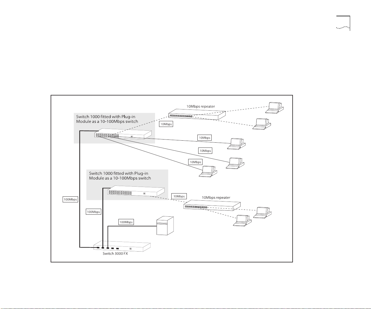
Network Segmentation I
This example shows how the Switch 1000 fits into
a large corporate network with a Fast Ethernet
infrastructure. A Switch is positioned on each floor
and servers are centralized in the basement.
Switch 1000 on Your Network 1-7
Figure 1-1
The Switch 1000 in a large corporate network
Page 16
1-8 C
HAPTER
1: G
ETTING STARTED
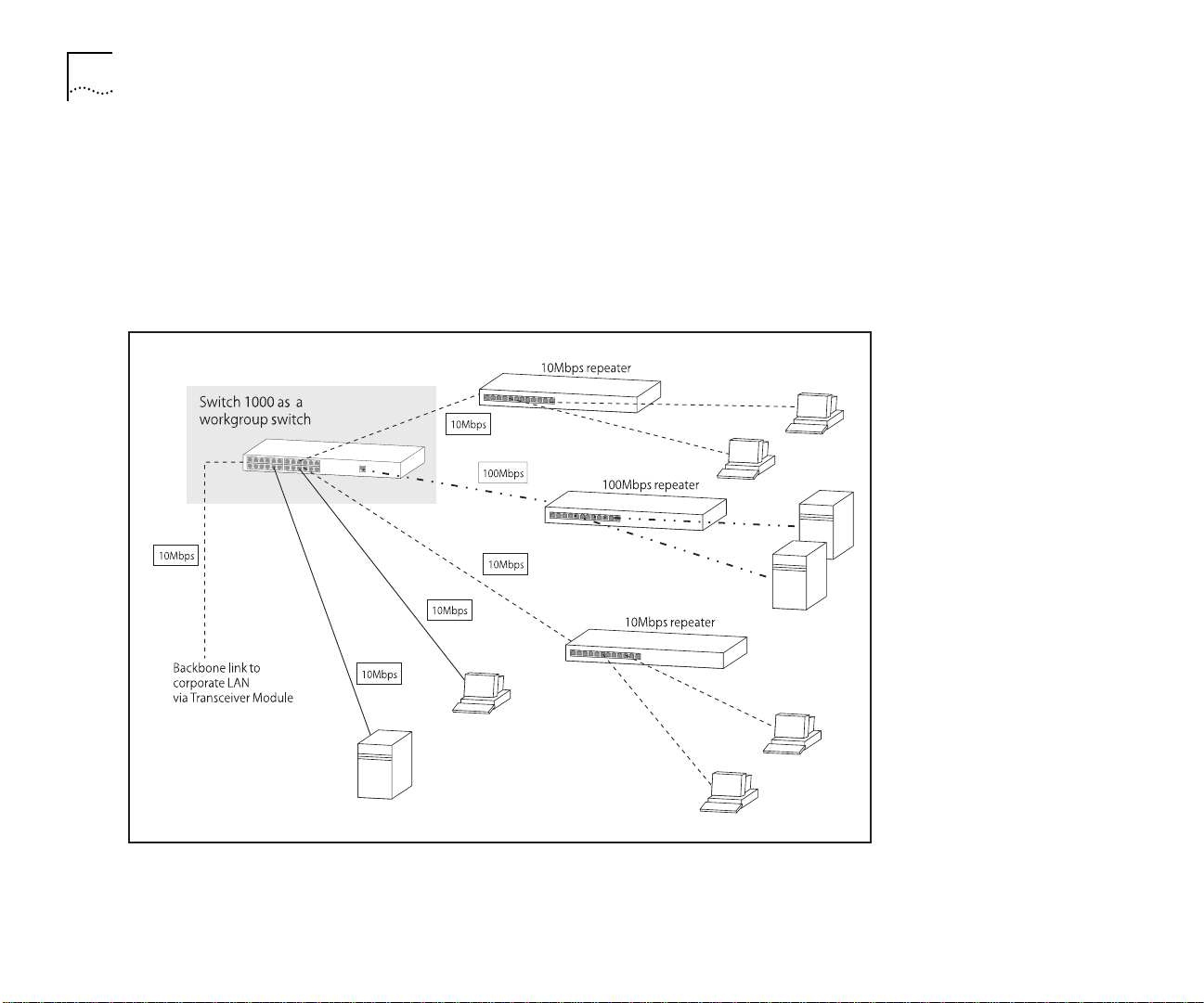
Network Segmentation II
This example shows the Switch 1000 in a second
workgroup situation. This setup could be that of a
small office within a large corporation, or part of a
larger corporate network. Most of the switch ports
have multiple endstations.
Figure 1-2
The Switch 1000 in a workgroup
Page 17
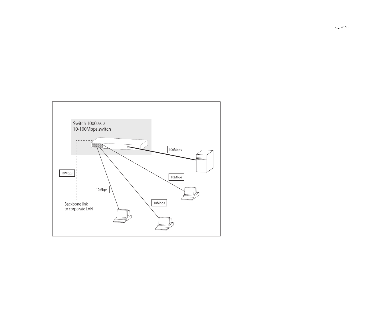
Desktop Switching
This example shows Switch 1000 used for a group of
heavy-traffic users in a large corporate network. Here
switching is brought to the desktop with a single
endstation per switch port. A local server is connected
using the 100Mbps Fast Ethernet link.
Switch 1000 on Your Network 1-9
Figure 1-3
The Switch 1000 as a desktop switch
Page 18
1-10 C
HAPTER
1: G
ETTING STARTED
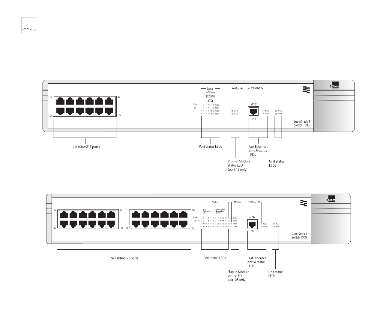
Unit Overview — Front
Figure 1-4
Switch 1000 front view: 3C16901A
top
, 3C16900A
bottom
Page 19

Unit Overview — Front 1-11
10BASE-T Ports
The Switch has 12 or 24 10BASE-T RJ45 ports configured as MDIX (cross-over), which provide a full
10Mbps bandwidth to attached endstations. The
maximum segment length is 100m (328ft) over category 3, 4, or 5 UTP cable.
As these ports are configured as MDIX (cross-over),
you need to use a cross-over cable to connect to
devices whose ports are MDIX-only. Most of the
10BASE-T ports in 3Com devices are MDIX-only.
100BASE-TX Port
The Switch has a single Fast Ethernet 100BASE-TX
RJ45 port configured as MDIX (cross-over), which
provides a 100Mbps connection to, for example, a
local server. The maximum segment length is 100m
(328ft) over category 5 UTP or STP cable.
As this port is configured as MDIX (cross-over), you
need to use a cross-over cable to connect to devices
whose ports are MDIX-only. Most of the
100BASE-TX ports in 3Com devices are MDIX-only.
LEDs
The table below describes the LED behavior on the
Switch. For more details about corrective action in
the event of a problem, refer to “
C-1.
LEDs” on page
LED Color Indicates
TCVR Yellow Port 1 is a Transceiver Module fitted to the
Port Status LEDs
Packet Yellow Frames are being transmitted/received on the
Status Green Link is present; port is enabled.
Green flashing Link is present; port is disabled.
Off Link is not present.
Plug-in Module Status LEDs
Packet Yellow Frames are being transmitted/received on the
Status Green Link is present; port is enabled.
Green flashing Link is present; port is disabled.
Green flashing
(long on, short
off)
Yellow Plug-in Module has failed its Power On Self
Yellow flashing Plug-in Module is not recognized.
Off Link is not present or Plug-in Module is not
Unit Status LEDs
Power
MGMT
Green Switch is powered-up.
Green Switch is operating normally.
Green flashing Switch or Plug-in Module is either down-
Yellow Switch has failed its Power On Self Test.
Yellow flashing Plug-in Module has failed its Power On Self
rear of the unit.
port.
Plug-in Module port.
Refer to the “
OC-3c Module User Guide”
Test (if the MGMT LED is flashing yellow), or
the agent software of the Plug-in Module is
not installed correctly.
installed in the Switch.
loading software or initializing (which
includes a Power On Self Test).
Tes t.
SuperStack II Switch ATM
.
Page 20
1-12 C
U
nit Overview — Rear
HAPTER
1: G
ETTING STARTED
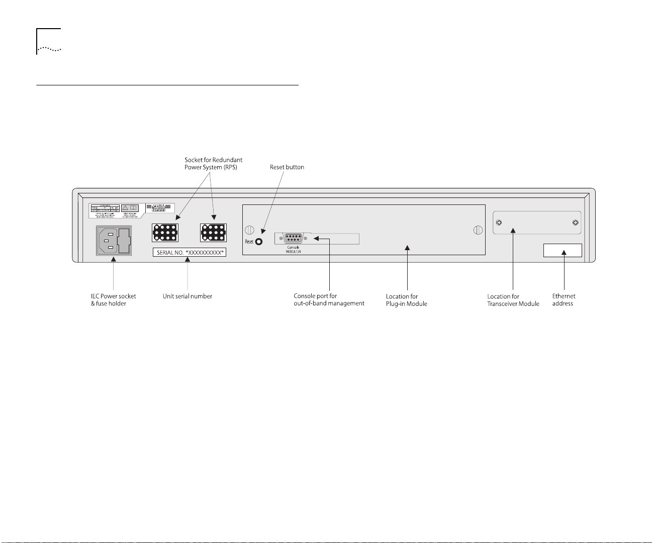
Figure 1-5
Switch 1000 rear view
Page 21
Unit Overview — Rear 1-13
Power Socket
The Switch 1000 automatically adjusts to the
supply voltage. The fuse is suitable for both 110V
A.C. and 220–240V A.C. operation. For information on replacing fuses, refer to Appendix A
Unit Serial Number
You may need this serial number for fault reporting
purposes.
Redundant Power System Socket
Use one of these sockets to connect a SuperStack II
Redundant Power System (RPS) to the unit. You can
use either socket. Refer to “
dant Power System (RPS)” on page 2-6.
Connecting a Redun-
Reset Button
Using the reset button simulates a power-off/on
cycle. This has the same effect as carrying out a
reset via the VT100 interface; refer to “
Switch” on page 4-27.
Console Port
Connect a terminal to the console port to carry out
remote or local out-of-band configuration and management. The console port is set to auto-baud, 8
data bits, no parity, and 1 stop bit.
.
Resetting the
Plug-in Module Slot
Use this slot to install a Plug-in Module. The Module
can be used to provide a high speed link to the rest
of your network. 3Com provides a range of Plug-in
Modules; contact your supplier for availability.
When a Plug-in Module is not installed, ensure the
blanking plate is secured in place.
Transceiver Module Slot
Use this slot to connect a Transceiver Module and
provide a 10Mbps link to the rest of the network.
Port 1 is automatically switched from the front
10BASE-T port to the Transceiver Module port
when a Module is installed. 3Com provides a range
of Transceiver Modules; contact your supplier for
availability.
When a Transceiver Module is not installed, ensure
the blanking plate is secured in place.
Ethernet Address
This label shows the unique Ethernet (or MAC)
address assigned to the unit.
Page 22

1-14 C
HAPTER
1: G
ETTING STARTED
Unit Defaults
The following table shows the factory defaults for
the Switch 1000 features.
Port Status
Forwarding Mode
Intelligent Flow
Management
Duplex Mode
Virtual LANs
PACE
Spanning Tree (STP)
Power On Self Test
(POST)
System Alarm
(broadcast bandwidth used)
System Alarm
(errors per 10,000
packets)
System Alarm
(bandwidth used)
System Alarm
(percentage of
frames forwarded)
Enabled
Fast Forward
Enabled
Half duplex on all relevant ports
All ports use Port VLAN Mode and belong to
the Default VLAN (VLAN 1)
Disabled
Disabled
Normal (Fast Boot)
Enabled
■
High threshold: 20% — Notify and Blip
■
Low threshold: 10% — No action
Enabled
■
High threshold: 2% — Notify
■
Low threshold: 1% — No action
Enabled
■
High threshold: 85% — No action
■
Low threshold: 50% — No action
Enabled
■
High threshold: 85% — No action
■
Low threshold: 50% — No action
Managing the Switch 1000
The menu-driven interface built into the Switch
1000 is known as the VT100 interface. You can
access it using a VT100 terminal, or a PC using terminal emulation software. You can connect the terminal directly to the Switch or through a modem.
You can also access the VT100 interface remotely
using Telnet running over the TCP/IP protocol.
Remote management is also possible using a Network Manager from 3Com’s Transcend
range. The management protocol is SNMP (Simple
Network Management Protocol) and any
SNMP-based management facility can manage the
unit if the Management Information Base (MIB) is
installed correctly in the management workstation.
The Switch 1000 supports SNMP over both IP and
IPX protocols.
®
product
Page 23
Quick Start For SNMP Users
This section describes how to get started if you
want to use an SNMP Network Manager to
manage the Switch. It assumes you are already
familiar with SNMP management.
If you are using IP and you have a BOOTP server
■
set up correctly on your network, the IP address
for the Switch is detected automatically and you
can start managing the Switch without any further configuration.
If you are using the IPX protocol, the Switch
■
1000 is allocated an IPX address automatically.
You can start the SNMP Network Manager and
begin managing the Switch.
If you are using IP without a BOOTP server, you
■
must enter the IP address of the Switch before
the SNMP Network Manager can communicate
with the device. To do this, refer to “
IP Address for the Switch” below.
Entering an
Quick Start For SNMP Users 1-15
At the Main Banner screen, press [Return] to dis-
3
play the Logon screen. Log on using the default
user name
admin
(no password is required). Select
OK.
The Main Menu is displayed. From this menu, select
4
the MANAGEMENT SETUP option. The Switch Management Setup screen is displayed.
On the Management Setup screen, fill in the follow-
5
ing fields:
Device IP Address
■
Device SubNet Mask (if necessary)
■
Default Router (if necessary)
■
For further information on the Management Setup
screen, refer to “
Setting Up the Switch for Manage-
ment” on page 3-6.
If you need the Switch 1000 to send SNMP traps to
6
the Network Manager, you may need to set up the
address of the Network Manager in the Trap Table.
Refer to “
Setting Up Traps” on page 4-24.
If you need more information about IP and IPX, refer
Managing Over The Network” on page 3-2.
to “
Entering an IP Address for the Switch
Connect a terminal to the console port of the
1
Switch 1000, refer to “
Connecting a VT100 Terminal” on page 2-7. The terminal should be config-
ured to 9600 line speed (baud rate), 8 data bits, no
parity, and 1 stop bit.
Press [Return] one or more times until the Main
2
Banner screen appears.
3Com Network Managers such as Transcend Enterprise Manager for Windows may automatically configure the Switch 1000 to send traps to them.
Please read the documentation supplied with your
network management software.
When you have finished with the Management
7
Setup screen, select OK.
Page 24

1-16 C
HAPTER
1: G
ETTING STARTED
Page 25

I
2
NSTALLATION AND
Following Safety Information
Before installing or removing any components from
the Switch, or carrying out any maintenance procedures, you must read the safety information provided in Appendix A
of this guide.
Positioning the Switch 1000
The Switch is suited for use in the office where it
can be wall-mounted, mounted in a standard
19-inch equipment rack, or free standing. Alternatively, the unit can be rack-mounted in a wiring
closet or equipment room. A wall-mounting /
rack-mounting kit, containing two mounting brackets and six screws, is supplied with the Switch.
When deciding where to position the unit, ensure
that:
S
ETU
P
Cabling is away from:
■
Sources of electrical noise such as radios,
■
transmitters and broadband amplifiers.
Power lines and fluorescent lighting fixtures.
■
Water or moisture cannot enter the case of the
■
unit.
Air-flow around the unit and through the vents in
■
the side of the case is not restricted. We recommend that you provide a minimum 25mm (1in.)
clearance.
No objects are placed on top of the unit.
■
Units are not stacked more than four high if
■
free-standing.
You are able to meet the configuration rules
■
detailed in the following section.
The unit is accessible and cables can be con-
■
nected easily.
Page 26

2-2 C
HAPTER
2: I
NSTALLATION AND SETUP
Configuration Rules for Fast Ethernet
The topology rules for 100Mbps Fast Ethernet are
slightly different to those for 10Mbps Ethernet.
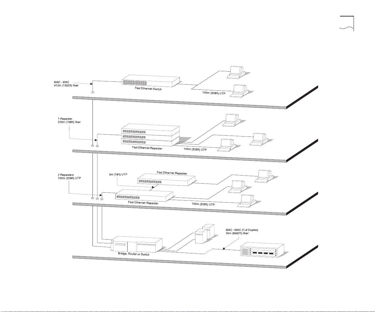
Figure 2-1 illustrates the key topology rules and provides examples of how they allow for large-scale
Fast Ethernet networks.
The key topology rules are:
■
Maximum UTP cable length is 100m (328ft) over
category 5 cable.
■
A 412m (1352ft) fiber run is allowed for connecting switch to switch, or endstation to switch,
using half-duplex 100BASE-FX.
■
A total network span of 325m (1066ft) is allowed
in single-repeater topologies (one hub stack per
wiring closet with a fiber run to the collapsed
backbone). For example, a 225m (738ft) fiber
downlink from a repeater to a router or switch,
plus 100m (328ft) UTP run from a repeater out to
the endstations.
With full duplex, the Ethernet topology rules are the
same, but the Fast Ethernet rules are:
■
Maximum UTP cable length is 100m (328ft) over
category 5 cable
■
A 2km (6562ft) fiber run is allowed for connecting switch-to-switch, or endstation-to-switch
Configuration Rules with Full Duplex
The Switch provides full duplex support for all its
fixed Ethernet and Fast Ethernet ports, and Fast
Ethernet Plug-in Module ports. Full duplex allows
frames to be transmitted and received simultaneously and, in effect, doubles the potential
throughput of a link.
Page 27
Configuration Rules with Full Duplex 2-3
Figure 2-1
Fast Ethernet configuration rules
Page 28
2-4 C
HAPTER
2: I
NSTALLATION AND SETUP
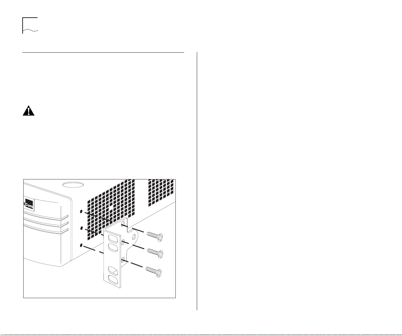
Installing the Switch 1000
Rack Mounting
The Switch is 1.5U high and fits in most standard
19-inch racks.
CAUTION: Disconnect all cables from the Switch
before continuing. Remove all self adhesive pads
from the underside of the unit, if fitted.
1
Place the unit the right way up on a hard flat surface, with the front facing towards you.
2
Locate a mounting bracket over the mounting
holes on one side of the unit, as shown in
Figure 2-2.
3
Insert the three screws and fully tighten with a suitable screwdriver.
4
Repeat steps 2 and 3 for the other side of the unit.
5
Insert the unit into the 19-inch rack and secure with
suitable screws (not provided). Ensure that ventilation holes are not obstructed.
6
Connect network cabling.
Stacking the Switch and Other Units
If the units are free standing, up to four units can
be placed on top of one another. If mixing a variety
of SuperStack II Switch and Hub units, the smaller
units must be positioned at the top.
The Switch is supplied with four self-adhesive rubber
pads. Apply the pads to the underside of the unit,
stick one in the marked area at each corner of the
unit. Place the units on top of each other, ensuring
that the pads of the upper unit line up with the
recesses of the lower unit.
Figure 2-2
Fitting a bracket for rack mounting
Page 29
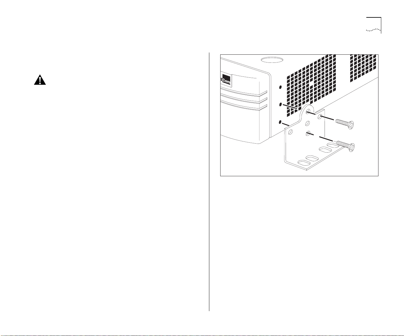
Wall Mounting
A single Switch can be wall-mounted.
Installing the Switch 1000 2-5
CAUTION:
Disconnect any cables from the unit
before continuing. Remove self-adhesive pads from
the underside of the unit if they have been previously fitted.
Place the Switch the right way up on a hard flat sur-
1
face, with the front facing towards you.
Locate a mounting bracket over the mounting
2
holes on one side of the unit, as shown in
Figure 2-3.
Insert the two screws and tighten with a suitable
3
screwdriver.
Repeat for the other side of the unit.
4
Ensure that the wall you are going to use is smooth,
5
flat, dry and sturdy. Attach a piece of plywood,
approximately 305mm x 510mm x 12mm (12in. x
20in. x 0.5in.) securely to the wall if necessary, and
mount the Switch as follows:
Position the base of the unit against the wall (or
a
plywood) ensuring that the ventilation holes face
sidewards. Mark on the wall the position of the
screw holes in both wall brackets. Drill the four
holes.
Figure 2-3
Fitting a bracket for wall mounting
Using suitable fixings and screws (not provided),
b
attach the Switch unit securely to the wall or plywood.
Connect network cabling.
c
Page 30

2-6 C
HAPTER
2: I
NSTALLATION AND SETUP
Powering-up the Switch
1
Connect the power cord to the IEC socket on the
rear of the Switch, and to your mains socket.
The Switch has no ON/OFF switch; the only method
of connecting or disconnecting mains power is
through the power cord.
2
The Switch enters a Power On Self Test (POST). The
time taken for the test to complete is dependent
on the type of POST configured (refer to “
Management Setup” on page 3-9 for details of how
to configure the type of POST). For a new Switch
that is being installed for the first time, power-up
takes approximately 13 seconds.
3
Check the status LEDs to ensure the Switch is operating correctly (refer to “
Switch
LEDs” on page 1-11).
Connecting a Redundant Power System (RPS)
You can connect a SuperStack® II Redundant Power
System (RPS) to the Switch.
At +5V, the current requirement for the Switch is
4.8A, including any Transceiver Module that might
be fitted, but excluding a Plug-in Module. Check the
documentation supplied with your Plug-in Module
for power consumption figures.
For most configurations, you need only one Superstack II RPS output, and this can be connected to
either of the two sockets on the rear of the unit.
If the current consumption of the Switch plus any
Plug-in Module exceeds the capability of the RPS
(8.5A), you need a SuperStack II Advanced RPS with
one Advanced RPS 100W Module.
If the RPS is used incorrectly, its Output Fault LED
lights yellow.
You should check the documentation supplied with
the RPS or Advanced RPS to see if the outputs can
be used in parallel.
Page 31

Connecting Equipment to the Console Port
The Switch console port settings are set to:
8 data bits
■
no parity
■
1 stop bit
■
The terminal connected to the console port on the
Switch must be configured with the same settings.
This procedure is described in the documentation
supplied with the terminal. If you have enabled
auto-configuration for the Switch, the terminal’s
line speed (baud rate) is detected automatically.
Connection to the console port can be direct for
local management, or through a modem for
remote management. The maximum baud rate the
auto-configuration detects is 19,200 baud.
Appropriate cables are available from your local supplier. If you need to make your own cables, pin-outs
are detailed in Appendix D
.
Connecting Equipment to the Console Port 2-7
Connecting a VT100 Terminal
To connect a VT100 terminal directly to the console
port on the Switch, you need a standard null
modem cable:
Connect one end of the cable to the console port
1
on the Switch, and the other to the console port on
the VT100 terminal.
Ensure that your terminal is set to:
2
8 data bits
■
no parity
■
1 stop bit
■
If auto-configuration is enabled for the Switch, the
terminal’s line speed (baud rate) is detected automatically.
Connecting a VT100 Terminal Emulator
Ensure that the workstation is running a suitable
1
terminal emulation package. There are many available; contact your local supplier for further details.
If you are using a PC, you need a null modem
2
cable with an appropriate connector. Connect one
end of the cable to the workstation, and the other
end to the console port on the Switch.
Ensure that your workstation is set to:
3
8 data bits
■
no parity
■
1 stop bit
■
If auto-configuration is enabled for the Switch, the
workstation’s line speed (baud rate) is detected
automatically.
Page 32

2-8 C
HAPTER
2: I
NSTALLATION AND SETUP
Connecting a Workstation Running SLIP
You can communicate with the Switch via the console port from a workstation running SLIP (Serial
Line Internet Protocol). In this way, you can perform
out-of-band management using Telnet or SNMP.
Cables required for this connection depend on the
type of workstation you are using. You must configure the workstation to run SLIP. Refer to the documentation supplied with the workstation for more
details.
You must configure the console port of the Switch
to accept SLIP and set up the SLIP parameters
(address and subnet mask). Refer to “
agement Setup” on page 3-9.
You may need a 5-wire cable when running SLIP.
Two of the wires are required for Flow Control.
Switch Man-
Page 33

3
S
ETTING
UP
FOR
Methods of Managing the Switch 1000
You can manage the Switch in four ways:
Using the VT100 interface by connecting a VT100
■
terminal (or workstation with terminal emulation
software) to the Switch console port.
Using the VT100 interface over a TCP/IP network
■
using a workstation running VT100 terminal
emulation and Telnet.
Using the VT100 interface by connecting a work-
■
station running SLIP to the Switch console port.
Using an SNMP Network Manager over a net-
■
work running either the IP or IPX protocol. Each
Network Manager provides its own user interface to the management facilities.
Using the VT100 Management Interface
The menu-driven user interface built into the
Switch is known as the VT100 or Local Manage-
ment interface. The VT100 management interface
provides a forms-based structure with pre-defined
security levels, enabling access to be restricted to
particular users. The Switch can support up to four
management user sessions concurrently (for example
one console port and three Telnet connections).
M
ANAGEMENT
You can establish VT100 management communication with the Switch through two different interfaces:
■
Via the Console Port
local management interface using a VT100 terminal, or PC using suitable terminal emulation software. The terminal can be connected directly to
the Switch, or through a modem. You can also
connect a management workstation running SLIP
to the console port, which allows you to use
out-of-band Telnet. The workstation can be connected directly or remotely, through a modem.
This method provides a way of managing the
Switch in situations where the LAN is not providing a reliable service, where the Network Manager does not have direct LAN connectivity, or
when a Network Manager does not support
SNMP.
■
Via a Network Connection
agement facility is also accessible via Telnet over a
network running the TCP/IP protocol. The management available through Telnet is exactly the
same as that of a locally connected terminal. The
Telnet application requires a VT100 terminal, or
PC using suitable terminal emulation software.
— You can access the
— The local man-
Page 34

3-2 C
HAPTER
Using Telnet
Any Telnet facility that emulates a VT100 terminal
should be able to communicate with the Switch
over a TCP/IP network. Up to three active Telnet sessions can access the Switch concurrently. If a connection to a Telnet session is lost inadvertently, the
connection is closed by the Switch after 2–3 minutes of inactivity.
Before you can start a Telnet session you must set
up the IP parameters described in “
ment Setup” on page 3-9.
3: S
ETTING UP FOR MANAGEMENT
Switch Manage-
Managing Over The Network
Any Network Manager running the Simple Network
Management Protocol (SNMP) can manage the
Switch, provided the MIB (Management Information Base) is installed correctly on the management
workstation.
Each Network Manager provides its own user interface to the management facilities. 3Com's
Transcend
facilities for managing the Switch.
®
range of Network Managers all have
To open the Telnet session, you must specify the IP
address of the device you want to manage. Check
the user manual supplied with the Telnet facility if
you are unsure how to do this.
Once the connection is established, the main banner
of the VT100 management interface is displayed
and you can log on.
The Switch supports SNMP over both IP and IPX
protocols.
IP Addresses
If you are uncertain about IP addresses that may be
assigned to your devices, contact your network
administrator first.
To operate correctly, each device on your network
must have a unique IP address. IP addresses have
the format n.n.n.n where n is a decimal number
between 0 and 255. An example IP address is:
191.128.40.120
The IP address can be split into two parts:
■
The first part (191.128 in the example) identifies
the network on which the device resides.
■
The second part (40.120 in the example) identifies the device within the network.
Page 35

If your network is internal to your organization
only, you may use any arbitrary IP address. We suggest you use addresses in the series 191.100.X.Y,
where X and Y are numbers between 1 and 254.
Use 191.101.X.Y for the SLIP address.
If your network has a connection to the external IP
network, you will need to apply for a registered IP
address. This system ensures that every IP address
used is unique; if you do not have a registered IP
address, you may be using an identical address to
someone else and your network will not operate
correctly.
Obtaining a Registered IP Address
InterNIC Registration Services is the organization
responsible for supplying registered IP addresses.
The following contact information is correct at the
time of publication:
Network Solutions
Attn: InterNIC Registration Service
505, Huntmar Park Drive
Herndon
VA 20170
U.S.A.
Managing Over The Network 3-3
Telephone: (1) (703) 742 4777
If you have access to the Internet, you can find further information about InterNIC by entering the following URL into your web browser:
http:/ /www. inte rnic .net
Page 36

3-4 C
HAPTER
3: S
ETTING UP FOR MANAGEMENT
Navigating the VT100 Screens
Screen Conventions
To differentiate types of information, the
VT100 screens use the following conventions:
Type of
information
Choice Field
Entry Field [
Button
List Box
Shown on screen
Description
as...
♦text♦
Text enclosed with markers is a list from which you can select one option only. Press [Space] to
cycle through the options. Press [Down Arrow] or [Return] to move to the next field.
text
] Text enclosed in square brackets on the screen is a
you to enter text, numeric data or hexadecimal data from the keyboard. Password fields are
hidden, which means that the text you type is not shown on the screen. In some cases a text
entry field has a default entry. If you wish to replace the default, simply enter a new value for
this field; the default entry is erased. Press [Down Arrow] or [Return] to move to the next field.
OK
Text for a button is always shown in uppercase letters. A button carries out an action, for
example, OK or CANCEL. To operate a button, move the cursor to the button and press
[Return].
monitor
manager
security
A list box allows you to select one or more items from a list. There are several keys that allow
you to use a list box.
■
[Return] moves the cursor to the next field and actions your selections.
■
[Space] toggles through the options in a choice field or selects and deselects an entry in the
list box. List box selections are highlighted.
■
[Down Arrow] moves item by item down the list box until it reaches the end of the list. At
the end of the list it moves the cursor to the next field.
■
[Ctrl] + [U] moves the cursor one page up the list box.
■
[Ctrl] + [D] moves the cursor one page down the list box.
text entry
field. A text entry field allows
Page 37

Navigating the VT100 Screens 3-5
Keyboard Shortcuts
There are several special characters or combinations
of characters that allow you to make shortcuts.
[Tab] allows you to move from one field to the next,
on any screen, without making any changes.
[Return] moves you to the next field on a form after
you have made changes to the data in a field.
[Left Arrow] moves you to the previous field on the
screen or the next character in an editable field.
[Right Arrow] moves you to the next field on the
screen or the previous character in an editable field.
[Ctrl] + [R] refreshes the screen.
[Ctrl] + [B] moves the cursor to the next button.
[Ctrl] + [P] aborts the current screen and returns you
to the previous screen.
[Ctrl] + [N] actions the inputs for the current screen
and moves to the next screen.
Correcting Text Entry
Use [Delete] on a VT100 terminal or [Backspace] on
a PC. This moves the cursor one space to the left
and deletes a character.
If you are using Telnet or a terminal emulation program you may find that some of the Control keys
do not operate or that they activate other functions.
Check carefully in the manual accompanying your
Telnet or terminal emulation software before using
the Control keys.
[Ctrl] + [K] displays a list of the available key strokes.
Page 38

3-6 C
HAPTER
3: S
ETTING UP FOR MANAGEMENT
Setting Up the Switch for Management
The following sections describe how to get started if
you want to use an SNMP Network Manager to
manage the Switch. It assumes you are already
familiar with SNMP management. If not, we recommend the following publication:
“The Simple Book”
by Marshall T. Rose
ISBN 0-13-812611-9
Published by Prentice Hall
■
If you are using IP and you have a BOOTP server
set up correctly on your network, the IP address
for the Switch is detected automatically and you
can start managing the Switch without any further configuration.
■
If you are using the IPX protocol, the Switch is
allocated an IPX address automatically. You can
start the SNMP Network Manager and begin
managing the Switch.
■
If you are using IP without a BOOTP server, you
must enter the IP address of the Switch before
the SNMP Network Manager can communicate
with the device. To do this, take the following
steps:
Figure 3-1
1
At your terminal, press [Return] two or more times
until the Switch 1000 Main Banner is displayed
(shown in Figure 3-1). The console port detects the
line speed (baud rate) from these keystrokes and
defaults to:
■
■
■
■
Data bits, parity and stop bit values cannot be
changed.
2
At the Main Banner, press [Return] to display the
Logon screen.
Main Banner
auto-baud
8 data bits
no parity
1 stop bit
Page 39

Logging On
At the Logon screen displayed in Figure 3-2, enter
your user name and password (note that they are
both case-sensitive):
If you have been assigned a user name and pass-
■
word, enter those details.
If you are logging on for the first time (after
■
installation or initialization), use a default user
name and password to match your access
requirements. The defaults are shown in
Table 3-1. If you are setting up the Switch for
management, we suggest that you log on first
as
admin
Setting Up the Switch for Management 3-7
.
Figure 3-2
Logon screen
Tab le 3 -1
User Name Default
monitor monitor monitor — this user can view, but not
manager manager manager — this user can access and
security security security — this user can access and
admin (no password) security — this user can access and
Default Users
Access Level
Password
change all manageable parameters
change the operational parameters
but not special/security features
change all manageable parameters
change all manageable parameters
Page 40

3-8 C
HAPTER
3: S
ETTING UP FOR MANAGEMENT
After Logging On
When you have successfully logged on to the
Switch, the Main Menu screen is displayed as shown
in Figure 3-3. From here, you can select the options
needed to manage the unit. Refer to the screen
map on page 4-1
.
If you have installed an ATM OC-3c Module into the
Switch, the Main Menu screen contains an ATM
CONFIGURATION option. Refer to the “SuperStack II
Switch ATM OC-3c Module User Guide” for more
information.
Access to options depends on the access level you
have been assigned. Access rights to the VT100
screens for the Switch are listed in Appendix B
Figure 3-3
Main Menu screen
.
If you are a user with
security
access level, and are
using the management facility for the first time, we
suggest that you:
■
Assign a new password for your user, using the
Edit User screen, as described in “
Editing User
Details” on page 4-5.
■
Log on as each of the other default users, and
change their passwords using the Edit User
screen.
■
Create any new users, in addition to the default
ones. To do this, you assign each user a name,
password and security level, as described in “
Cre-
ating a New User” on page 4-3.
Page 41

Switch Management Setup
The Management Setup screen allows you to configure IP, IPX and SLIP parameters for the Switch.
This screen also allows you to display screens for
setting up the console port and traps.
To access the Setup screen, from the Main Menu
screen, select the MANAGEMENT SETUP option. The
Setup screen appears as shown in Figure 3-4.
If you change some of the following parameters,
the Switch must be reset for the change to take
effect. Reset the Switch by selecting OK and pressing the Reset button on the rear of the unit. Refer
Unit Overview — Rear” on page 1-12.
to “
The screen shows the following:
MAC Address
This read-only field shows the MAC
address of the Switch unit, which is required for
management.
Power On Self Test Type
field allows you to determine the type of self-test
that the Switch carries out when it is powered-up. If
the field is set to
Normal,
Fast Boot — a basic confidence check lasting
approximately 13 seconds. When the Switch performs a Fast Boot, it carries out the following tests:
Checksum test of boot and system areas of Flash
■
memory
System memory tests
■
MAC address verification test
■
System timer test
■
Normal / Extended
This
the Switch performs a
Figure 3-4
■
■
■
■
■
■
■
■
■
If the field is set to
an Extended test which may take up to 70 seconds
to complete. When the Switch performs an
Extended test, it carries out the Fast Boot tests and
more extensive tests on system memeory and ASIC
memory. The default setting for the field is
Setting Up the Switch for Management 3-9
Management Setup screen
CAM (Contents Addressable Memory) tests
Console port tests
Internal packet forwarding tests
ASIC (Application Specific Integrated Circuit) tests
ASIC memory tests
Switch–Plug-in Module interface test
Plug-in Module packet forwarding tests
Plug-in Module ASIC tests
Plug-in Module ASIC memory tests
Extended
, the Switch performs
Normal
.
Page 42

3-10 C
HAPTER
3: S
ETTING UP FOR MANAGEMENT
If you suspect that there is a problem with the
Switch that has not been detected by the Normal
tests, set this field to Extended and reset the Switch
(refer to “
Resetting the Switch” on page 4-27).
If you set the Switch to perform an Extended test,
the Switch must be disconnected from the rest of
your network when it is powered-up. The Switch
fails an Extended test if it receives any network traffic during the test.
Device IP Address
If you are using IP, a unique IP
address must be specified in this field. If you do not
know the IP address of the Switch, consult your network administrator. You must reset the Switch after
changing this parameter.
Device SubNet Mask
If you are using IP, enter a
suitable network mask. For a Class B IP address,
255.255.0.0 is suitable. For more information, contact your network administrator. You must reset the
Switch after changing this parameter.
Default Router
If a default router exists on your
network, enter the IP address of the router. You
must reset the Switch after changing this parameter.
BOOTP Select
Enabled / Disabled
If BOOTP is
enabled and you have a BOOTP server on your network, an IP address is automatically mapped to the
Switch when it is first powered up. In addition to
mapping an IP address, BOOTP can also assign the
subnet mask and default router. Using a BOOTP
server avoids having to configure devices individually.
SLIP Address
If you are using SLIP, enter an address
that has a network part different to the network
address of the Switch. For more information, contact your network administrator. You must reset the
Switch after changing this parameter.
SLIP SubNet Mask
Enter a suitable SubNet Mask.
For a Class B address, 255.255.0.0 is suitable. For
more information, contact your network administrator. You must reset the Switch after changing this
parameter.
There are four entries under the following four
fields; one for each data link layer protocol that can
be used by IPX:
IPX Network
This read-only field shows the address
of the network for this protocol. This address is
learned automatically from the local IPX router or
NetWare File Server, and you do not need to change
it.
This read-only field shows the node address
Node
of the Switch which is learned automatically.
Status
Enabled / Disabled
If this field is set to
Enabled, you have access to the medium-access protocol. Set this field to Disabled if you wish to prevent access for security reasons.
Data Link Protocol
This read-only field shows the
name of the IPX data link layer protocol.
Page 43

Setting Up the Switch for Management 3-11
SETUP TRAPS
Select this button to display the
setup screen for trap parameters. Trap setup is
described in “
CONSOLE PORT
Setting Up Traps” on page 4-24.
Select this button to display the
setup screen for console port parameters. Console
port setup is described in “
Setting Up the Console
Port” on page 4-25.
Page 44
3-12 C
HAPTER
Logging Off
If you have finished using the VT100 management
interface, select the LOGOFF option from the
bottom of the Main Menu screen. If you accessed
the VT100 management interface using a Telnet session or modem connection, the connection is
closed automatically.
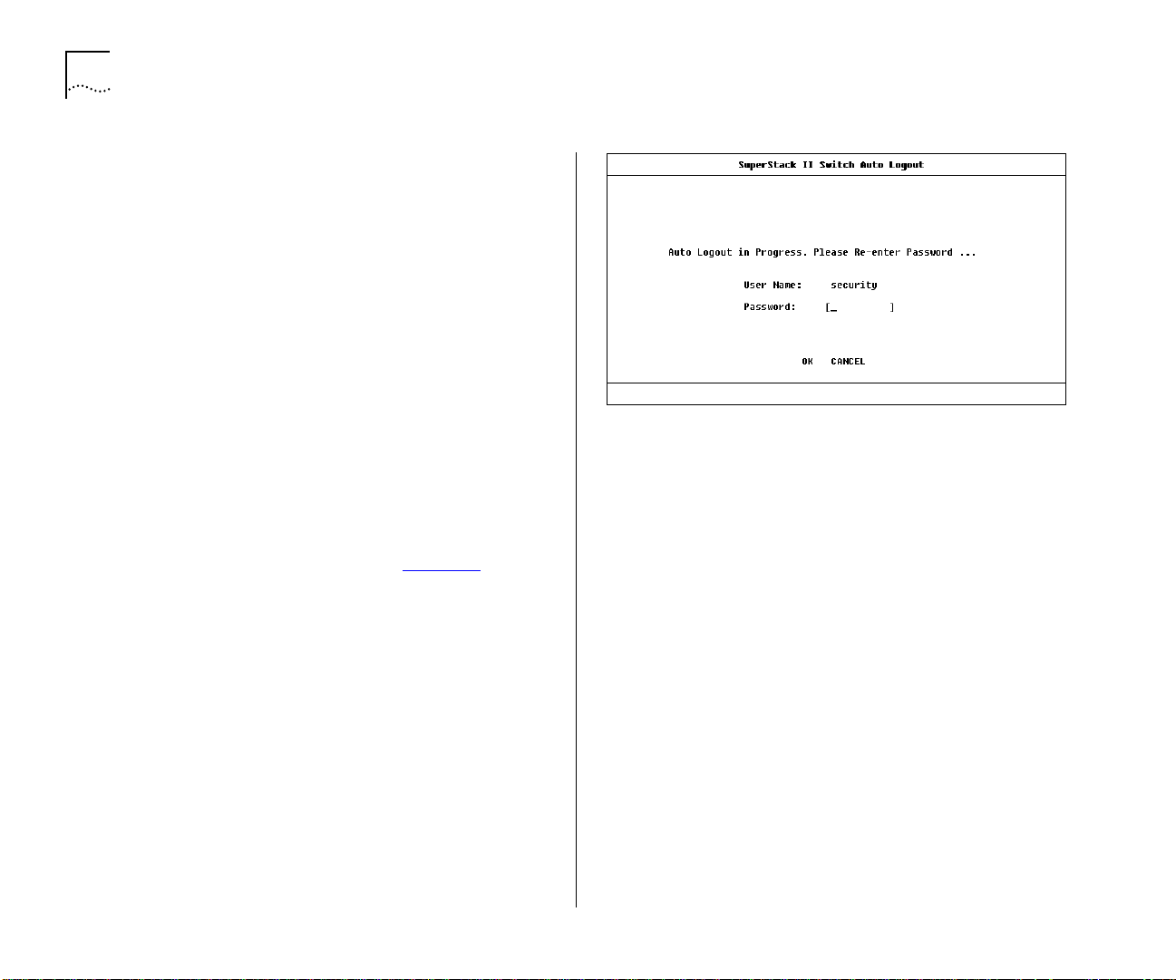
Auto Logout
There is a built-in security timeout on the VT100
interface. If you do not press any keys for 3 minutes, the management facility warns you that the
inactivity timer is about to expire. If you do not
press a key within 10 seconds, the timer expires and
the screen is locked; any displayed statistics continue
to be updated. When you next press any key, the
display changes to the Auto Logout screen.
3: S
ETTING UP FOR MANAGEMENT
Figure 3-5
Auto Logout screen
The Auto Logout screen (shown in Figure 3-5
)
requests you to enter your password again. If the
password is correctly entered, the screen that was
active when the timer expired is displayed. If you
make a mistake entering your password, you are
returned to the Logon screen.
Page 45

4
M
ANAGING
T
H
E
S
WITCH
1000
Chapters 4, 5 and 6 describe all management facilities
for the Switch 1000. While following steps in these
chapters, you may find the screen map below useful:
If an ATM OC-3c Module is installed in the Switch,
extra screens are available. Refer to the
“SuperStack
Guide” for more information.
®
II Switch ATM OC-3c Module User
Figure 4-1
Screen map
Page 46

4-2 C
HAPTER
4: M
Setting Up Users
From the Main Menu, select USER ACCESS LEVELS.
The User Access Levels screen appears as shown in
Figure 4-2
From this screen you can access:
■
LOCAL SECURITY screen
set up access levels for users on the Switch.
■
CREATE USER screen
create up to 10 users in addition to the default
users set up on the Switch.
■
DELETE USERS screen
delete users from the Switch. The default users
cannot be deleted.
■
EDIT USER screen
your own password and community string. You
cannot change details for other users.
.
ANAGING THE SWITCH
— This allows you to
— This allows you to
— This allows you to
— This allows you to change
1000
Figure 4-2
User Access Levels screen
Page 47

Creating a New User
These steps assume the User Access Levels screen is
displayed.
Select the CREATE USER option. The Create User
1
screen is displayed, as shown in Figure 4-3
Fill in the fields and assign an access level for the
2
new user.
When the form is complete, select OK.
3
Creating a New User 4-3
.
The Create User screen shows the following fields:
User Name
Type in the name of this new user. The
name can consist of up to 10 characters and is
case-sensitive.
Password
Type in the password for this new user.
The password can consist of up to 10 characters
and is case-sensitive. For security reasons, the password is not displayed on screen.
Access Level
Assign an access level for this new
user, as follows:
monitor
■
— access to view, but not change, a
subset of the manageable parameters of the
Switch
secure monitor
■
manager
■
— access to all the manageable param-
— as
monitor
eters of the Switch, except security features
Figure 4-3
■
■
Community String
identical to the user name is generated. You can
change this to any text string of 32 characters or
less. The community string is only needed for SNMP
access. If you are using a remote SNMP Network
Manager, the community string specified in the Network Manager’s database must be the same as that
for the device.
If you enter a community string that is greater than
32 characters, it is truncated to 32 characters.
Create User screen
specialist
security
— as
— access to all manageable parameters
of the Switch
manager
By default, a community string
Page 48

4-4 C
HAPTER
4: M
Deleting a User
These steps assume the User Access Levels screen is
displayed.
1
Select the DELETE USERS option. The Delete Users
screen is displayed, as shown in Figure 4-4
2
Use the spacebar to highlight the user that you
want to delete. Note that you cannot delete default
users or the current user (that is, yourself).
3
Select DELETE USERS.
ANAGING THE SWITCH
1000
.
Figure 4-4
Delete Users screen
Page 49

Editing User Details
These steps assume the User Access Levels screen is
displayed.
Select the EDIT USER option. The Edit User screen is
1
displayed, as shown in Figure 4-5
Fill in the fields as required.
2
When you have completed the changes, select OK.
3
The Edit User screen shows the following fields:
Editing User Details 4-5
.
User Name
This read-only field shows the name of
the user. This field cannot be changed; if you need
to change the user name, you must delete this user
and create a new one.
Old Password
To change the user’s password, enter
the current password in this field.
New Password
This field allows you to enter a new
password for the user.
Confirm Password
This field allows you to
re-enter the new password.
Community String
This field allows you to enter a
community string for the user.
If you forget your password while logged out of
the Switch VT100 interface, contact your local technical support representative who will advise on your
next course of action.
Figure 4-5
Edit User screen
Page 50

4-6 C
HAPTER
4: M
ANAGING THE SWITCH
Assigning Local Security
The Local Security screen shows a matrix of options
for access method (Console Port, Remote Telnet,
Community-SNMP) and access level.
These steps assume the User Access Levels screen is
displayed.
1
Select the LOCAL SECURITY option. The Local Security screen is displayed, as shown in Figure 4-6
2
Fill in the fields as required.
3
When you have filled in the form, select OK.
Access options are:
1000
.
Figure 4-6
Local Security screen
Console Port
Enabled / Disabled
To prevent access
to the management facilities via the console port,
disable access to the facility for each access level.
Console port access for
Security
is enabled and
cannot be changed. This prevents accidental disabling of all access levels from management.
Remote Telnet
Enabled / Disabled
Telnet is an insecure protocol. You may want to disable all access
to the management facilities via Telnet if there is
important or sensitive data on your network.
Community-SNMP
Enabled / Disabled
The Switch
can be managed via SNMP using a remote Network
Manager. Community-SNMP does have some
simple security features, but it is an insecure protocol. You may want to disable all access to the management facilities if there is important or sensitive
data on your network.
Page 51

Choosing a Switch Management Level
The Switch Management screen allows you to:
Choose between managing a port, the unit, or a
■
VLAN
Display screens for setting up the Switch
■
Display a screen for managing the Switch Data-
■
base
Display screens for managing resilient links
■
Display screens for managing STP
■
Display screens showing statistics
■
From the Main Menu, select SWITCH MANAGEMENT. The Switch Management screen is displayed,
as shown in Figure 4-7
.
Figure 4-7
Choosing a Switch Management Level 4-7
Switch Management screen for Port level (3C16900A)
Management Level
choose
Figure 4-7
Port
, the screen is displayed similar to
, and all options at the foot of the screen
Port / Unit / VLAN
relate to an individual port. If you choose
screen appears similar to Figure 4-8
relate to the Switch unit. If you choose
screen appears similar to Figure 4-9
If you
Unit
, the
, and all options
VLAN
, the
, and all options
relate to VLANs.
Port ID
1 / 2 / 3 / ... 24 / 25 / 26
1 / 2 / 3 / ... 12 / 13 / 14
(3C16900A)
(3C16901A) If you choose
to manage the Switch at port level, enter the particular port number into this field before selecting the
next screen. For 3C16900A, ports 1–24 are the
10BASE-T ports, port 25 is the Plug-in Module port
at the rear of the unit, and port 26 is the
100BASE-TX port.
Figure 4-8
For 3C16901A, ports 1–12 are the 10BASE-T ports,
port 13 is the Plug-in Module port at the rear of the
unit, and port 14 is the 100BASE-TX port.
Switch Management screen for Unit level
Page 52

4-8 C
STP
HAPTER
4: M
ANAGING THE SWITCH
1000
Use this button to display screens for managing
Spanning Tree Protocol (STP) information for the
level of management you have chosen (port or
VLAN). Refer to “
Spanning Tree Protocol” on page
5-12.
STP is not supported over Asynchronous Transfer
Mode (ATM). Consequently, if you specify that you
want to manage the Plug-in Module and the
Switch has an ATM OC-3c Module installed, the
STP button is not displayed.
SERVER
Use this button to display the VLAN Server
screen, used for entering the IP address and community string of a VLAN server. For more information about VLAN servers, refer to “
Virtual LANs
(VLANs)” on page 5-1.
STATS
Use this button to display statistics screens for
the level of management you have chosen (port or
unit). Refer to Chapter 6
SDB
Use this button to display the Unit Database
.
View screen, which is used to manage the Switch
Database. Refer to “
The Database View” on page
4-17.
RESILIENCE
Use this button to display resilient link
management screens for the level of management
you have chosen (port or unit). Refer to “
Setting
Up Resilient Links” on page 4-19.
You cannot set up resilient links if the Switch uses
Spanning Tree (STP). Consequently, the RESILIENCE
button is not displayed if STP is enabled.
Figure 4-9
SETUP
the level of management you have chosen (port,
unit or VLAN). For information about the Port
Setup and Unit Setup screens, refer to “
the Switch Ports” and “Setting Up the Switch Unit”
in this chapter. For information about the VLAN
Setup screen, refer to “
Switch” on page 5-8.
Switch Management screen for VLAN level
Use this button to display setup screens for
Setting Up
Setting Up VLANs on the
Page 53

Setting Up the Switch Unit
With the Switch Management screen displayed,
choose the management level
SETUP button.
The Unit Setup screen is displayed as shown in
Figure 4-10
. The screen shows the following:
Unit
, then select the
Setting Up the Switch Unit 4-9
Unit Name
This read-only field shows the type of
device.
sysName
This field takes its name from the MIB II
System Group object. You can edit the first 30 characters of this field to make the name more meaningful. This name is displayed on the Main Banner
when you first access the VT100 screens, and is also
accessible to an SNMP Network Manager.
Forwarding Mode
Store and Forward / Intelligent
Fast Forward / Fragment Free /
This field allows you
to set the forwarding mode for the Switch:
Fast Forward
■
— Frames are forwarded as soon
as the destination address is received and verified.
The forwarding delay, or latency, for all frames in
this mode is just 40µs but with the lack of checking time, error frames are propagated onto the
network.
Fragment Free
■
— A minimum of 512 bits of the
received frame is buffered prior to the frame
being forwarded. This ensures that collision fragments are not propagated through the network.
The forwarding delay, or latency, for all frames in
this mode is 64µs.
Figure 4-10
Store and Forward
■
ered in their entirety prior to forwarding. This
ensures that only good frames are passed to their
destination. The forwarding delay for this mode
varies between 64µs and 1.2ms, depending on
frame length. In this mode the latency, measured
as the time between receiving the last bit of the
frame and transmitting the first bit, is 8µs.
Intelligent
■
of error traffic on the network and changes the
forwarding mode accordingly. If the Switch
detects less than 18 errors a second, it operates
in Fast Forward mode. If the Switch detects
more than 18 errors a second, it operates in
Store and Forward mode until the number of
errors returns to zero.
Intelligent Forwarding
Forward
state if the Forwarding Mode is set to Intelligent.
Unit Setup screen (3C16900A)
— Received packets are buff-
— The Switch monitors the amount
Fast Forward / Store and
This read-only field shows the forwarding
Page 54

4-10 C
HAPTER
4: M
ANAGING THE SWITCH
1000
Enable / Disable
PACE
This field allows you to
enable or disable PACE (Priority Access Control
Enabled) for all ports on the Switch. PACE allows
multimedia traffic to be carried over standard Ethernet and Fast Ethernet LANs by providing two features:
■
Implicit Class of Service
— When multimedia traffic is transmitted, it is given a higher priority
than other data and is therefore forwarded ahead
of other data when it arrives at the Switch. The
Implicit Class of Service feature minimizes latency
through the Switch and protects the quality of
multimedia traffic.
■
Interactive Access
— When two-way multimedia
traffic passes over an Ethernet network, interference can occur because access to the bandwidth
is unequally allocated to traffic in one direction.
The Interactive Access feature allocates the available bandwidth equally in both directions, therefore increasing the quality of the traffic.
Interactive Access should only be enabled on ports
that connect to a single endstation, switch, bridge
or router. You should disable Interactive Access on
a port if it is connected to a repeater. Also, Interactive Access should only be enabled at one end of
the link.
For more information about disabling Interactive
Access for a port, refer to “
Setting Up the Switch
Ports” on page 4-12.
VLAN Configuration Mode
Port / AutoSelect
This
field allows you to specify how ports on the Switch
are placed in VLANs:
■
Port
— The ports use Port VLAN Mode, which
means that they are manually placed in the
required VLAN. This is the default mode.
■
AutoSelect
— The ports use AutoSelect VLAN
Mode, which means that they are automatically
placed in the required VLAN by referring to a
®
VLAN Server database in 3Com’s Transcend
Enterprise Manager software.
For more information, refer to “
Using AutoSelect
VLAN Mode” on page 5-3.
Bridging Mode
bone
This field allows you to set the bridging mode,
Forward To All / Forward To Back-
which controls how packets with unknown
addresses are processed:
■
Forward To All
— The Switch forwards packets
with an unknown address to all ports in the same
VLAN as the source port. This setting should
only be used if your network has less than 500
MAC addresses.
■
Forward To Backbone
— The Switch forwards
packets with an unknown address to the backbone port defined for the VLAN of the source
port. This is the default setting.
For more information about VLANs and backbone
ports, refer to “
Virtual LANs (VLANs)” on page 5-1.
Page 55

Setting Up the Switch Unit 4-11
SDB Ageing Time
This field allows you to specify
the ageing time (hours:minutes) for all non-permanent entries in the Switch Database of the unit.
You can set an ageing time in the range 0 minutes
to 277 hours, with a default of 30 minutes. If you
enter 0:00, ageing is turned off. For more information about ageing times, refer to “
Setting Up the
Switch Database (SDB)” on page 4-16.
Spanning Tree
Enable / Disable
This field allows
you to enable or disable the Spanning Tree Protocol
(STP) on the Switch. For more information about
STP, refer to “
Spanning Tree Protocol” on page
5-12.
Duplex Mode
Ports / Full Duplex on all Ports
Half Duplex / Full Duplex on 100M
This field allows you
to set the duplex mode of ports that have Unit
Default specified in the Duplex Mode field of the
Port Setup screen. The default setting is Half Duplex.
For more information about Duplex Mode, refer to
Setting Up the Switch Ports” on page 4-12.
“
1 / 2 / 3 / ... 24 / 25 / 26
Backbone Port
(3C16900A)
1 / 2 / 3 /...12 / 13 / 14
(3C16901A)
If the Bridging Mode field is set to Forward to Backbone, and all the ports on the Switch belong to
VLAN 1 and use Port VLAN Mode, then this field
allows you to specify a backbone port for the
Switch. In all other situations, the field is not displayed.
For more information about VLANs, refer to “
Virtual LANs (VLANs)” on page 5-1. For more informa-
tion about backbone ports and their role in VLAN
functionality, refer to “
Setting Up VLANs on the
Switch” on page 5-8.
Default RMON Host/Matrix
Enable / Disable
This
field allows you to enable (start) Hosts and Matrix
RMON sessions on the Default VLAN, or disable
(stop) existing sessions if they are no longer
required. The default setting for this field is Disable.
For more information about RMON sessions, refer to
RMON” on page 5-22.
“
Plug-in Module Type
This read-only field displays
the type of Plug-in Module fitted to the rear of the
unit, or displays Not Fitted.
Transceiver Module Type
This read-only field
shows the type of Transceiver Module fitted to the
rear of the unit, or displays Not Fitted.
Power Supply
Internal / External
This read-only
field displays External if the Switch is receiving
power from a Redundant Power System. In all
other cases, this field displays Internal.
On a new or initialized Switch, all ports belong to
VLAN 1 and use Port VLAN Mode.
Page 56

4-12 C
HAPTER
4: M
ANAGING THE SWITCH
Setting Up the Switch Ports
With the Switch Management screen displayed,
choose the management level
appropriate port, then select the SETUP button.
The Port Setup screen is displayed as shown in
Figure 4-11
If the port is an ATM OC-3c Module port, the ATM
Port Setup screen is displayed. For more information, refer to the “SuperStack II Switch ATM OC-3c
Module User Guide”.
The screen shows the following:
Port ID
you have chosen to set up.
Media Type
type of the link connected to this port.
Port Speed
and duplex mode of the link. HD indicates half
duplex, FD indicates full duplex.
Port State
enable or disable the port. To prevent unauthorized
access, we recommend that you disable any unused
ports.
Link State
field shows the state of the link:
■
Present
■
Not Available
.
This read-only field shows the ID of the port
This read-only field shows the media
This read-only field shows the speed
Enable / Disable
Present / Not Available
— The port is operating normally
— The link has been lost
1000
Port
. Choose the
This field allows you to
This read-only
Figure 4-11
Lost Links
times the link has been lost since the Switch was
last reset. If the number in this field is not zero, you
should check your cables and replace any that may
be damaged.
If the port is directly connected to an endstation,
the Lost Links counter increments each time the
endstation goes through a power-off/on cycle.
Intelligent Flow Management
This field allows you to enable or disable Intelligent
Flow Management (IFM). IFM minimizes packet loss
which can occur with conventional switches.
IFM should be disabled if the port is connected to a
repeated segment where the traffic is mainly local
to that segment. Refer to “
Chapter 1
Port Setup screen (10BASE-T port)
This read-only field shows the number of
Enable / Disable
Server Connections” in
.
Page 57

Setting Up the Switch Ports 4-13
IFM is not available on a port which has full duplex
enabled:
If the Duplex Mode field in this screen is set to
■
Full Duplex, the Intelligent Flow Management
field is not displayed
In all other cases where the port has full duplex
■
enabled, IFM has no effect
Security
Enable / Disable
When Security is enabled,
the port enters single address learning mode. The
Switch removes all addresses currently stored in the
Switch Database against the port. The Switch then
learns the source address from the first packet it
receives on the port since Security was enabled.
Once the first address is learnt, no other endstation
is permitted to access the network through the port.
If an endstation with a different address attempts to
transmit packets onto the network through the
port, the port is automatically disabled and a trap is
generated. The port remains disabled until it is
enabled from the Port Setup screen or via SNMP
management.
A more comprehensive set of security features is
available through SNMP network management.
Disable Interactive Access
Yes / N o
This field
allows you to disable the Interactive Access feature
of PACE (Priority Access Control Enabled) on the
current port. You should disable Interactive Access
on a port if:
The port is connected to a repeater
■
The port is connected to a device with Interac-
■
tive Access enabled
For more information about the Interactive Access
feature, refer to “
page 4-9
.
VLT Mode
Setting Up the Switch Unit” on
Enable / Disable
This field allows you to
specify whether the port is a VLT (Virtual LAN Trunk)
port. A Virtual LAN Trunk (or VLT) is a
Switch-to-Switch link which carries traffic for all the
VLANs on each Switch. To create a VLT, the ports on
both ends of the link must be VLT ports. For more
information about VLTs, refer to “
VLANs and the
Switch” on page 5-3.
If the port uses AutoSelect VLAN Mode (refer to
the VLAN Configuration Mode field), you cannot
specify that the port is a VLT port.
Security is not available on backbone ports. If the
port has been defined as a backbone port, the
Security field is not displayed.
Page 58

4-14 C
Duplex Mode
Default
4: M
HAPTER
ANAGING THE SWITCH
Half Duplex / Full Duplex / Unit
This field allows you to specify the duplex
mode of the port:
■
Full Duplex
— Full duplex allows frames to be
transmitted and received simultaneously and, in
effect, doubles the potential throughput of a link.
In addition, full duplex also supports
100BASE-FX cable runs of up to 2km. You should
only enable full duplex on a point to point link
between the Switch and another device with full
duplex support.
Full duplex is not supported on the Transceiver
Module port.
■
Half Duplex
— You should use half duplex if the
port connects to a shared Ethernet or Fast Ethernet LAN segment, or if the device at the other
end of a point-to-point link does not support full
duplex.
■
Unit Default
— The duplex mode of the port is
defined by the Duplex Mode field in the Unit
Setup screen. This is the default setting.
VLAN Configuration Mode
Unit Default
This field allows you to specify how the
Port / AutoSelect /
port is placed in a VLAN:
■
Port
— The port uses Port VLAN Mode, which
means that the port is manually placed in the
required VLAN.
1000
■
AutoSelect
— The port uses AutoSelect VLAN
Mode, which means that the port is automatically
placed in the required VLAN by referring to a
VLAN Server database in 3Com’s Transcend Enterprise Manager software.
■
Unit Default
— The port uses Port VLAN Mode or
AutoSelect VLAN Mode depending on the contents of the VLAN Configuration Mode field in
the Unit Setup screen. This is the default setting.
For more information, refer to “
Using AutoSelect
VLAN Mode” on page 5-3.
Broadcast Storm Control
The Switch automatically creates an alarm on each of its ports to monitor the level of broadcast traffic on each port. The
Broadcast Storm Control fields allow you to specify
thresholds for the level of broadcast traffic on a
port, and specify an action to take place if the
threshold is exceeded.
Rising Threshold%
This field allows you to specify
the percentage of broadcast traffic on the current
port which triggers the alarm for the port. The
default is 20%.
Falling Threshold%
This field allows you to specify
the percentage of broadcast traffic on the current
port required to reset the alarm for the port. The
falling threshold prevents the rising threshold
events being triggered continuously. The default is
10%.
Page 59

Setting Up the Switch Ports 4-15
Rising Action
disable port/notify / blip / blip port/notify
none / event / disable port /
Use this
field to specify the action for the alarm to take
when it reaches the rising threshold:
none
■
■
■
■
— no action takes place
event
— an SNMP trap is generated
disable port
disable port/notify
— the port is disabled
— the port is disabled and an
SNMP trap is generated
blip
— the broadcast and multicast traffic on the
■
port is blocked for five seconds
blip port/notify
■
— the broadcast and multicast
traffic on the port is blocked for five seconds,
and an SNMP trap is generated
If
user defined
is displayed in the Rising Action field,
an unrecognized action has been specified using a
MIB browser. You cannot select this option.
none / event / enable /
Falling Action
event + enable
Use this field to specify the action
for the alarm to take when it reaches the falling
threshold:
none
■
■
■
■
— no action takes place
event
— an SNMP trap is generated
enable
— the port is enabled
event + enable
— the port is enabled and an
SNMP trap is generated
If
user defined
is displayed in the Rising Action field,
an unrecognized action has been specified using a
MIB browser. You cannot select this option.
You should be aware of the following points when
using Broadcast Storm Control:
The Switch takes 5–7 seconds to recognize that a
■
broadcast storm is occurring.
Broadcast Storm Control calculates the average
■
broadcast bandwidth over the previous
20-second interval. The average is based on four
samples taken at 5-second intervals.
When the average value exceeds the rising
■
threshold value, the rising action is triggered.
The action is not triggered again until the average broadcast bandwidth falls below the falling
threshold level.
Page 60

4-16 C
HAPTER
4: M
ANAGING THE SWITCH
1000
Setting Up the Switch Database (SDB)
The Switch maintains a database of device addresses
that it receives on its ports. It uses the information
in this database to decide whether a frame should
be forwarded or filtered. The database holds up to a
maximum of 500 entries; each entry consists of the
MAC address of the device and an identifier for the
port on which it was received.
If you have set up Traps for the Switch, notification
that the database is becoming full is provided by
two traps:
■
Database is 90% full
■
Database is 100% full
These traps indicate that the maximum number of
devices which can be connected to the Switch has
been reached. You cannot connect any more devices
to the Switch. Additional devices can, however, be
connected to the rest of the network.
Entries are added into the Switch Database in two
ways:
■
The Switch can learn entries. That is, the unit
updates the SDB with the source MAC address,
and the port identifier on which the source MAC
address is seen. Addresses are not learned on
the backbone port. Learning is affected by security (refer to the description for the Security field
on page 4-13
).
■
The system administrator can enter and update
entries using a MIB browser, an SNMP Network
Manager or the Switch Database screen
described in the following sections.
There are three types of entries in the SDB:
■
Ageing entries
— Initially, all entries in the database are ageing entries. Entries in the database
are removed (aged out) if, after a period of time
(ageing time), the device has not transmitted.
This prevents the database from becoming full
with obsolete entries by ensuring that when a
device is removed from the network, its entry is
deleted from the database. Ageing entries are
deleted from the database if the Switch is reset
or a power-off/on cycle occurs. For more information about setting an ageing time, refer to “
ting Up the Switch Unit” on page 4-9.
■
Non-ageing entries
— If the ageing time is set
to 0:00, all ageing entries in the database are
defined as non-ageing entries. This means that
they do not age, but they are still deleted if the
Switch is reset or a power off/on cycle occurs. For
more information about setting an ageing time,
refer to “
Setting Up the Switch Unit” on page
4-9.
■
Permanent entries
— Permanent entries do
not age, and they are retained in the database if
the Switch is reset or a power-off/on cycle occurs.
Set-
Page 61

The Database View
The Unit Database View screen, as shown in
Figure 4-12
, allows you to view and configure the
Switch Database.
To access the Unit Database View screen, display the
Switch Management screen, choose the management level
Unit
The Unit Database View screen shows the following:
Setting Up the Switch Database (SDB) 4-17
, then select the SDB button.
Database Entries
This read-only field shows the
number of entries currently in the SDB. The database holds a maximum of 500 addresses.
MAC Address
If you highlight an entry in the listbox and press [Return], this field shows the MAC
address for the entry.
Port Number
If you highlight an entry in the list-
box, this field shows the port identifier for the entry.
Permanent
This field allows you to specify
Yes / No
that the current entry is permanent. Refer to the
previous section “
Setting Up the Switch Database
(SDB)” for a description of permanent and ageing
entries.
You cannot specify that the current entry is permanent if the port uses AutoSelect VLAN Mode. For
more information about AutoSelect VLAN Mode,
refer to “
Using AutoSelect VLAN Mode” on page
5-3.
Figure 4-12
A listbox containing three fields:
Port
MAC Address
currently stored in the database.
Permanent
permanent, or No if this entry is ageing or
non-ageing.
FIND
database. Refer to “
base” on page 4-18.
REFRESH
it displays the latest information.
Unit Database View screen
The port ID for the entry.
The MAC address for the port
Yes / N o
Shows
Yes
if this entry is
This button lets you locate an entry in the
Searching the Switch Data-
This button refreshes the database so that
Page 62

4-18 C
HAPTER
4: M
ANAGING THE SWITCH
1000
INSERT
This button lets you insert an entry into the
database. You cannot insert an entry for a port
which uses AutoSelect VLAN Mode.
DELETE
This button allows you to delete entries
from the database. You cannot delete an entry if it
is associated with a port which uses AutoSelect
VLAN Mode.
Searching the Switch Database
You can search the switch database in two ways:
by MAC address or port number.
By MAC Address
To locate the port number against which a particular
MAC address is entered in the SDB:
1
In the MAC Address field, type in the MAC address
you are trying to locate.
2
Select FIND. The port ID is displayed in the Port
Number field and the entry in the listbox is highlighted with an asterisk (*).
By Port
To locate the MAC addresses entered against a particular port ID in the SDB:
1
Clear the MAC Address field by moving into the
field and pressing [Space].
2
In the Port Number field, enter the port ID for which
you want MAC addresses displayed.
3
Select FIND. The listbox will show entries in the
database for that port only.
Adding an Entry into the SDB
1
In the MAC Address field, type in the MAC address
of the device.
2
In the Port field, type in the port identifier for this
device.
3
Select whether the entry is permanent or not by
specifying Yes or No in the Permanent field.
4
Select INSERT.
Deleting an Entry from the SDB
1
In the listbox, highlight the entry you want to delete
and press [Return], or type the MAC address into
the MAC Address field.
2
Select DELETE.
Specifying that an Entry is Permanent
1
In the listbox, highlight the entry you want to make
permanent and press [Return], or type the MAC
address into the MAC Address field.
2
In the Permanent field, specify Yes.
3
Select INSERT.
Page 63

Setting Up Resilient Links
You can configure a Switch to provide resilient links
to another device so that network disruption is minimized if a link fails. A
main link and a standby link. You define a resilient
link pair by specifying the main port and standby
port at one end of the pair.
Figure 4-13
Resilient link pair
resilient link pair
consists of a
Setting Up Resilient Links 4-19
When setting up resilient links, you should note the
following:
Up to 13 resilient link pairs can be configured on
■
a 24-port Switch 1000, and up to seven pairs can
be configured on a 12-port Switch 1000.
Resilient links cannot be set up if Spanning Tree
■
(STP) is enabled on the Switch.
Resilient Links can only be set up on fiber or
■
twisted pair links. The main and standby links in
the same pair, however, can use any combination of these media.
A resilient link pair can only be set up if:
■
The ports belong to the same VLAN.
■
The ports have an identical security setting.
■
Neither of the ports forms part of another
■
resilient link pair.
If the main port is VLT (Virtual LAN Trunk) port,
■
the standby port must also be a VLT port.
Under normal network operating conditions, the
main link carries your data. The Receive Idle signal
of a fiber link or the Test Pulse on an Ethernet
twisted pair link is continually monitored by the
Switch. If a signal loss is detected, the Switch immediately enables the standby port so that it carries the
data. In addition, the main port is disabled.
If a main link has a higher bandwidth than its
standby link, traffic is automatically switched back to
the main link provided no loss of link is detected for
two minutes. Otherwise, you need to manually
switch traffic back to the main link.
A resilient link pair must be defined at only one
■
end of the connection.
You cannot disable any port that is part of a resil-
■
ient link pair.
Page 64

4-20 C
HAPTER
4: M
ANAGING THE SWITCH
Configuring Resilient Links
With the Switch Management screen displayed,
choose the port that will be set up as the main
port in the resilient link pair, then select the RESILIENCE button.
The Port Resilience screen is displayed as shown in
Figure 4-14
. This screen allows you to setup, edit
and delete resilient link pairs.
The screen shows the following:
1000
Main Port ID
This read-only field shows the ID of
the main port.
Media Type
Twisted Pair / Fiber
This read-only field
shows the media type connected to the main port.
Link State
Available / Not Available / Not Present
This read-only field shows the connection state of
the main port:
■
Available
■
Not Available
■
Not Present
— The port is operating normally
— The resilient link pair is disabled
— The port is not present in the cur-
rent hardware
Standby Port ID
This field shows the current
standby port ID and allows you to enter a new port
ID. The standby port must be in the same VLAN as
the main port.
Media Type
Twisted Pair / Fiber
This read-only field
shows the standby port media type.
Figure 4-14
Link State
This read-only field shows the connection state of
the standby port:
■
Available
■
Not Available
■
Not Present
rent hardware
Standby Links Available
ports that you can configure as standby.
Pair State
Not Available
operating state of the resilient link pair:
■
Active
operating normally with both main and standby
port capable of carrying traffic.
Port Resilience screen
Available / Not Available / Not Present
— The port is operating normally
— The resilient link pair is disabled
— The port is not present in the cur-
This listbox shows the
Active / Both Failed / Unknown /
This read-only field shows the current
— The resilient link pair is enabled and
Page 65

Setting Up Resilient Links 4-21
Both Failed
■
— Although the resilient link is correctly configured, both links have failed. This
could be due to loose connections or cable damage.
Unknown
■
— The network configuration has
changed and the resilient link pair no longer conforms to the rules.
Not Available
■
Active Port
— The resilient link pair is disabled.
Main / Standby
If a main link does
not
have a higher bandwidth than its standby link, traf-
not
fic is
automatically switched back to the main
link when it recovers. Use this field to manually
switch traffic back to the main link.
Pair Enable
Enabled / Disabled
Use this field to
enable or disable the resilient link pair. Before you
disable a resilient link pair, you must remove
cabling from the ports to avoid creating loops in
your network configuration.
Creating a Resilient Link Pair
Ensure that the port nominated as the standby port
1
is not physically connected to the unit.
Ensure both ports have an identical port security
2
mode configuration and that they are members of
the same VLAN.
At the Switch Management screen, select the port
3
to be configured as the main port in the link. Select
the RESILIENCE button at the foot of the screen.
Select the standby port from the Standby Links
4
Available listbox or enter the port ID in the Standby
Port ID field.
Enable the pair in the Pair Enabled field. Select
5
APPLY.
Connect the cabling for the standby port.
6
Deleting a Resilient Link
To delete the resilient link set up on the port, select
the DELETE button at the foot of the screen. The
Port Resilience screen closes and the Switch Management screen is displayed.
Page 66

4-22 C
HAPTER
4: M
ANAGING THE SWITCH
Viewing the Resilient Setup
With the Switch Management screen displayed,
choose the management level
RESILIENCE button.
The Unit Resilience Summary screen is displayed as
shown in Figure 4-15
. This screen shows the current resilient link configuration for the unit, and
allows you to access the Port Resilience screen for
resilient link pairs.
The following information is displayed:
1000
Unit
and select the
MAIN Port
This read-only field displays the ID of
the port configured as the main port for the resilient
link pair.
STANDBY Port
This read-only field displays the ID
of the port configured as the standby port for the
resilient link pair.
Pair State
Available
Active / Both Failed / Unknown / Not
This read-only field displays the current
state of the resilient link pair:
■
Active
— The resilient link pair is enabled and
operating normally, with both main and standby
ports capable of carrying traffic.
■
Both Failed
— Although the resilient link is correctly configured, both links have failed. Check
for any loose connections or cable damage.
■
Unknown
— The network configuration has
changed and the resilient link pair no longer conforms to the rules.
■
Not Available
— The resilient link pair is disabled.
Figure 4-15
Active Port
read-only field displays which port in the resilient
link pair is currently carrying traffic:
■
Main
with the main port carrying traffic.
■
Standby
standby port is carrying the traffic. You should
rectify the fault as soon as possible. If a main
port has a higher bandwidth than the standby
port, traffic will be automatically switched back
provided no loss of link is detected for two minutes. Otherwise, set the Active Port setting in
the Port Resilience screen (described on page
4-20) to Main to manually switch traffic back.
■
Both Failed
have failed. This could be due to loose connections or cable damage.
Unit Resilience Summary screen
Main / Standby / Both Failed
This
— The pair is operating in its normal state
— The main port has failed and the
— Both ports of the resilient link pair
Page 67

Setting Up Resilient Links 4-23
Pair Enable
Enabled / Disabled
This read-only field
displays whether the resilient link pair is currently
enabled or disabled. You enable or disable a resilient
link pair using the Port Resilience screen described in
Configuring Resilient Links” on page 4-20.
“
This button allows you to access the Port Resil-
OK
ience screen for the current resilient link pair.
Page 68

4-24 C
HAPTER
4: M
Setting Up Traps
Traps are messages sent across the network to an
SNMP Network Manager. They alert the network
administrator to faults or changes at the Switch
device.
Your Network Manager may automatically set up
traps in the Switch Trap Table. Check the documentation accompanying your network management
software.
ANAGING THE SWITCH
1000
To access the Trap Setup screen, select the SETUP
TRAPS button from the Management Setup screen
(described in Chapter 3
shown in Figure 4-16
). The Trap Setup screen is
.
The screen shows the following:
IP or IPX Address
This field allows you to enter the
IP or IPX address of the remote network management stations to which traps should be sent.
Community String
This field allows you to enter
community strings for each remote Network Manager, allowing a very simple method of authentication between the Switch and the remote Network
Manager. The text string can be of 32 characters or
less. If you want a Network Manager to receive
traps generated by the device, you must enter the
community string of the Network Manager into the
trap table. The default community string is
public
.
Figure 4-16
Throttle
delay value for each remote Network Manager.
Throttle delays are time periods placed between
packets to prevent a remote Network Manager
receiving too many traps at once. The unit of throttle is one thousandth of a second. The default
value is 100, which gives a delay of one tenth of a
second between each packet transmission.
Trap Setup screen
This field allows you to specify a throttle
Page 69

Setting Up the Console Port
From the Switch Management Setup screen,
described in Chapter 3
button. The Console Port Setup screen is displayed
as shown in Figure 4-17
If you change any of the console port parameters,
you terminate any existing sessions using the console port when you exit the screen. Ensure that the
connected equipment’s console port parameters are
set to match the new configuration. This allows
you to continue to access the management facility
from the equipment after you change the console
port parameters.
The screen shows the following:
Connection Type
you to select the type of console port connection.
Remote
Select
if you want to manage the Switch
through a modem; DCD Control and DSR Control
are enabled. For all other cases, this field should be
Local
set to
DCD Control
.
Enabled / Disabled
applicable to local connection types. It determines if
DCD is required for a local connection, and
whether the connection is closed if DCD is removed.
Refer to your terminal or modem user documentation if you are unsure of the correct setting.
, select the CONSOLE PORT
.
Local / Remote
This field allows
This field is only
Figure 4-17
DSR Control
applicable to local connection types. It determines if
DSR is required for a local connection, and whether
the connection is closed if DSR is removed. Refer to
your terminal or modem user documentation if you
are unsure of the correct setting.
Flow Control
RTS-CTS Unidirectional / RTS-CTS Bidirectional
This field allows you to select the correct flow control option for your terminal or modem. Refer to
your terminal or modem documentation if you are
unsure of the correct setting.
Auto Config
auto configure the line speed (baud rate) to work
with your VT100 terminal. This field allows you to
specify whether auto-configuration is enabled.
Setting Up the Console Port 4-25
Console Port Setup screen
Enabled / Disabled
XON/XOFF / NONE /
Enabled / Disabled
This field is only
The Switch can
Page 70

4-26 C
HAPTER
4: M
ANAGING THE SWITCH
1000
Speed
1200 / 2400 / 4800 / 9600 / 19200
This field allows you to select the correct line speed
(baud rate) for your terminal or modem. If you
have enabled auto-configuration, line speed is set
automatically.
Char Size
8 This read-only field shows the character
bit (data bit) size for the Switch. You should set your
terminal to the same value.
NONE
Parity
This read-only field shows the parity
setting for the Switch. You should configure your
terminal to the same setting.
Stop Bit
1 This read-only field shows the stop bit
setting for the Switch. You should configure your
terminal to the same setting.
Page 71

Resetting the Switch
If you suspect a problem with the Switch, you can
reset it.
From the Main Menu, select the RESET option.
1
The Reset screen is displayed as shown in
Figure 4-18
Select OK.
2
Resetting the Switch in this way is similar to performing a power-off/on cycle. No setup information
is lost.
.
Figure 4-18
Resetting the Switch 4-27
Reset screen
CAUTION:
Performing a reset may cause some of
the data being transmitted at that moment to be
lost.
Page 72

4-28 C
HAPTER
4: M
ANAGING THE SWITCH
Initializing the Switch
This screen allows you to perform a reset as
described in the previous section, and in addition,
returns non-volatile data stored on the unit to its
factory defaults (shown on page 1-14
the IP address is not cleared. You should only initialize the Switch if:
■
The configuration of the device no longer suits
your network
■
Other efforts to solve problems have not succeeded
To initialize the Switch:
1
From the Main Menu, select the INITIALIZE option.
The Initialize screen appears as shown in
Figure 4-19
2
Select OK.
CAUTION: Use the Initialize option with great care.
The Switch configuration is cleared from memory
and cannot be recovered. After initialization, all
user information is lost and only default users are
available. All ports are set to their default values,
and are therefore enabled and available to all users.
.
1000
). Note that
Figure 4-19
■
VLT ports fail and you are not able to manage
the Switch if your management station communicates via the VLT. To avoid this:
a
Remove the VLT configuration from both ends of
the VLT link before you initialize the Switch.
Note that the port furthest from your management station should have its VLT configuration
removed first.
b
Reconfigure the VLT once the initialization is complete.
Initialize screen
When initializing the Switch, take particular note of
the following:
■
Network loops occur if you have set up resilient
links. Before initializing the Switch, ensure you
have disconnected the cabling for all your
standby links.
Page 73

Upgrading Software
When 3Com issues a new version of agent software
for the Switch, you can obtain it from the 3Com’s
information delivery systems described in “
Technical Services” on page F-1.
For upgrading the ATM OC-3c Module software,
refer to the “SuperStack II Switch ATM OC-3c
Module User Guide”.
You use the Software Upgrade screen to download
new software images. The protocol used for downloading software images is TFTP running over
UDP/IP or IPX.
CAUTION:
the following:
The download only works over the network; it
■
does not work through the console port.
The download does not work over a Virtual LAN
■
Trunk (VLT) if you have a Boot software version
lower than version 2.0.
The download does not work over an ATM link.
■
If a software download over IPX fails, enter the
MAC or Ethernet address of your server into the
Switch Database via the Unit Database View screen
and then attempt the download again. Refer to
Searching the Switch Database” on page 4-18.
“
Before attempting to download, note
Online
Figure 4-20
To upgrade Switch management software:
From the Main Menu, select the SOFTWARE
1
UPGRADE option.
The Software Upgrade screen is displayed, as
shown in Figure 4-20
From the Destination field, select Switch (this is the
2
default).
In the File Name field, enter the name of the file
3
that contains the software image to be downloaded to the Switch.
You must place the image file where it is accessible
to the TFTP load request. Check with your system
administrator if you are unsure of where to place
the image file.
In the Server Address field, enter the IP or IPX
4
address of the server containing the software image
to be loaded.
Upgrading Software 4-29
Software Upgrade screen
.
Page 74

4-30 C
5
Select OK.
HAPTER
4: M
ANAGING THE SWITCH
1000
During the download, the MGMT LED flashes green
and the screen is locked. When the download is
complete, the Switch is reset.
Page 75

5
A
DVANCED
Virtual LANs (VLANs)
Setting up Virtual Local Area Networks (VLANs) on
the Switch 1000 provides you with less timeconsuming network administration and more efficient network operation.
M
ANAGEMENT
With VLANs, you can define your network according
to:
■
Departmental groups
have one VLAN for the Marketing department,
another for the Finance department, and
another for the Development department.
— For example, you can
The following sections explain more about the concept of VLANs and explain how they can be implemented on the Switch 1000.
What are VLANs?
A VLAN is defined as a group of location- and
topology-independent devices that communicate as
if they are on the same physical LAN. This means
that LAN segments are not restricted by the hardware which physically connects them; the segments
are defined by flexible user groups that you create
using software.
■
Hierarchical groups
have one VLAN for directors, another for managers, and another for general staff.
■
Usage Groups
one VLAN for users of e-mail, and another for
users of multimedia.
Benefits of VLANs
Implementing VLANs on your network has three
main advantages:
It eases the change and movement of devices on
■
IP networks
It helps to control broadcast traffic
■
It provides extra security
■
— For example, you can
— For example, you can have
Page 76
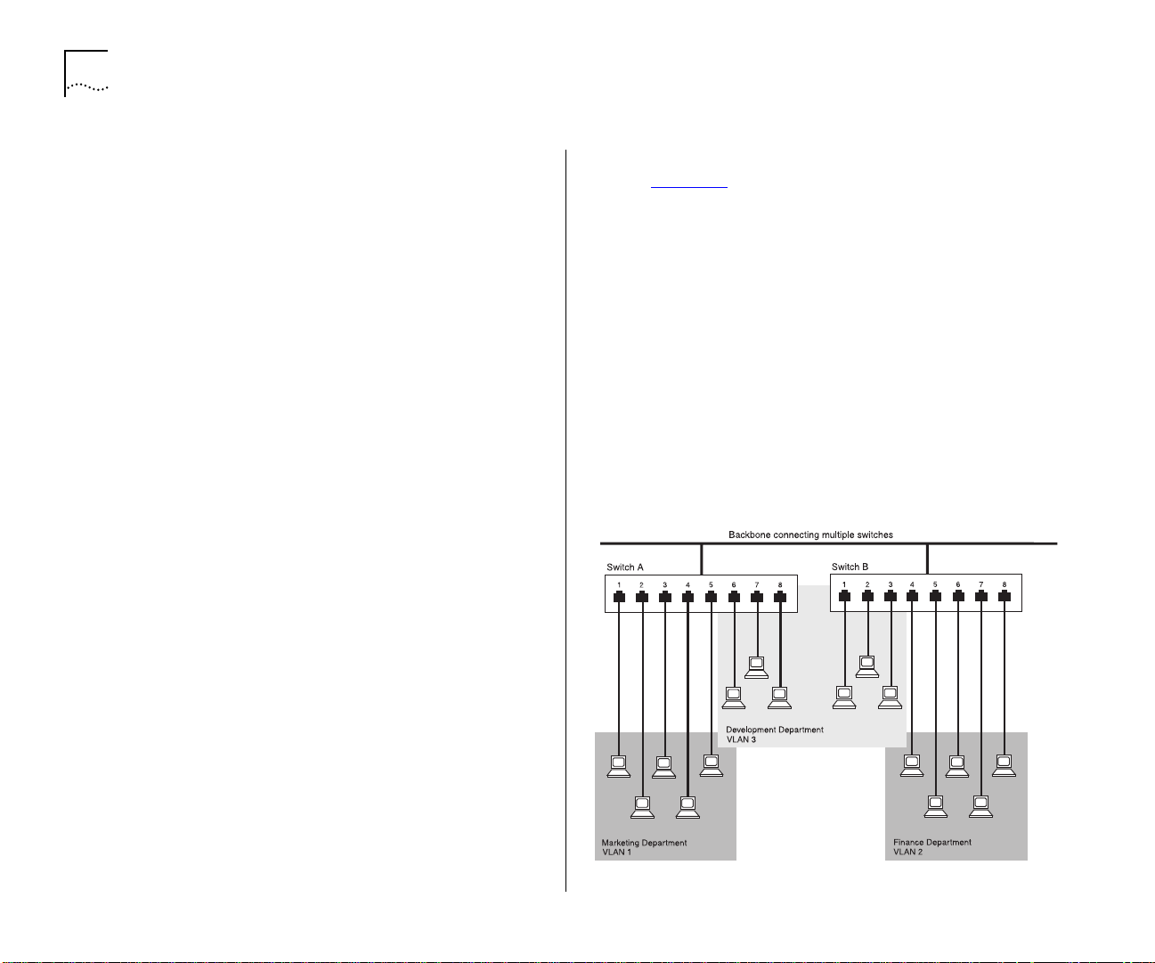
5-2 C
HAPTER
5: A
DVANCED MANAGEMENT
How VLANs Ease Change and Movement
With traditional IP networks, network administrators spend much of their time dealing with moves
and changes. If users move to a different IP subnet,
the IP addresses of each endstation must be
updated manually.
With a VLAN setup, if an endstation in VLAN 1 is
moved to a port in another part of the network,
you only need to specify that the new port is in
VLAN 1. This is something that can be done auto-
®
matically if you have 3Com’s Transcend
Enterprise
Manager for Windows (v6.0 and above).
How VLANs Control Broadcast Traffic
With traditional networks, congestion can be caused
by broadcast traffic which is directed to all network
devices whether they require it or not. VLANs
increase the efficiency of your network because
each VLAN can be set up to contain only those
devices which need to communicate with each
other.
How VLANs Provide Extra Security
An Example
Figure 5-1 shows a network configured with three
VLANs — one for each of the departments who
access the network. The membership of VLAN 1 is
restricted to ports 1, 2, 3, 4 and 5 of Switch A;
membership of VLAN 2 is restricted to ports 4, 5,
6, 7 and 8 of Switch B while VLAN 3 spans both
Switches containing ports 6, 7, 8 of Switch A and 1,
2, 3 of Switch B.
In this simple example, each of these VLANs can be
seen as a
ments that are not constrained by their physical
location.
Specific configurations using the Switch are shown
later in this chapter.
broadcast domain
— physical LAN seg-
Devices within each VLAN can only communicate
with devices in the same VLAN. If a device in VLAN
1 needs to communicate with devices in VLAN 2,
the traffic must cross a router.
Figure 5-1
The concept of VLANs
Page 77

Virtual LANs (VLANs) 5-3
VLANs and the Switch
The Switch 1000 supports VLANs which consist of
a set of switch ports. Each switch port can only
belong to one VLAN at a time, regardless of the
device to which it is attached.
Each Switch 1000 can support up to 16 VLANs.
However, you can have more than 16 VLANs in your
entire network by connecting the 16 Switch VLANs
to other VLANs using a router.
The Default VLAN and Moving Ports From the
Default VLAN
On each Switch, VLAN 1 is the Default VLAN of the
Switch; it has two properties:
It contains all the ports on a new or initialized
■
Switch
It is the only VLAN which allows an SNMP Net-
■
work Manager to access the management agent
of the unit
By default, if a device is attached to a port in the
Default VLAN and you want to move the device into
another VLAN, you need to use the VLAN Setup
screen to place the port in that VLAN. For more
information about the VLAN Setup screen, refer to
Setting Up VLANs on the Switch” on page 5-8.
“
Connecting VLANs to a Router
If the devices in a VLAN need to talk to devices in a
different VLAN, each VLAN requires a connection to
a router. Communication between VLANs can only
take place if they are all connected to the router. A
VLAN not connected to a router is an isolated
VLAN. You need one port for each VLAN connected
to the router.
Connecting Common VLANs Between Switch
Units
If you want to connect the VLANs on the Switch
1000 with the same VLANs on another Switch unit,
you can set up one link per VLAN. Alternatively,
you can set up a single link for all the VLANs by creating a
Virtual LAN Trunk
(VLT). A VLT is a
Switch-to-Switch link which carries traffic for all the
VLANs on each Switch. To set up a VLT, you configure the port at each end of the link.
VLTs can only be used for links between Super-
®
II Switch 1000, Switch 3000 and Desktop
Stack
Switch units. You cannot use VLTs for Switch–router
links.
If you specify that a port on one VLAN is a VLT port,
that port carries traffic for all the VLANs on the
Switch. If you then disable the VLT function on that
port, the port only carries traffic for the Default
VLAN (VLAN 1).
Using AutoSelect VLAN Mode
By default, all ports on the Switch use Port VLAN
Mode — where each switch port is
manually
placed in the required VLAN. The Switch allows
some ports to use another mode, AutoSelect VLAN
Mode. In this mode, the ports are
automatically
placed in the required VLAN by referring to a VLAN
Server database in 3Com’s Transcend Enterprise
Manager v6.0 for Windows.
Page 78

5-4 C
HAPTER
5: A
DVANCED MANAGEMENT
AutoSelect VLAN Mode works as follows:
1
When an endstation is connected to a Switch or
moves from one port to another, the Switch learns
the MAC address of the endstation.
Figure 5-2
2
If the relevant port uses AutoSelect VLAN Mode, the
Switch learns the endstation’s MAC address
Switch interrogates the VLAN Server to determine
the VLAN membership of the endstation.
Figure 5-3
3
Having obtained the VLAN membership for the end-
Switch interrogates the VLAN Server
station, the Switch places the relevant port in the
specified VLAN.
Figure 5-4
Switch places the port in the VLAN
AutoSelect VLAN Mode has an advantage over Port
VLAN Mode because once the VLAN Server database is set up correctly, you can move endstations to
other ports or other Switch units and the VLAN allocation of each endstation is automatically configured.
If you use AutoSelect VLAN Mode, note the following:
■
You need to specify an IP address and community
string for the VLAN Server.
■
You cannot use VLAN 15.
■
If a port has been configured as a backbone
port or as a VLT port, the port cannot use
AutoSelect VLAN Mode.
■
If a port has a permanent address stored against
it in the Switch Database, the port cannot use
AutoSelect VLAN Mode.
■
We recommend that you connect each switch
port to a single endstation. If you want to connect a port to multiple endstations, specify that
the port uses Port VLAN Mode.
Page 79

Virtual LANs (VLANs) 5-5
For information about how to set up VLANs using
AutoSelect VLAN Mode, refer to Chapter 5
page 5-11
.
on
For more information about the VLAN Server database, refer to the documentation supplied with
3Com’s Transcend Enterprise Manager.
Using Non-routable Protocols
If you are running non-routable protocols on your
network (for example, DEC LAT or NET BIOS),
devices within one VLAN are not able to communicate with devices in a different VLAN.
Using Unique MAC Addresses
If you connect a server with multiple network adapters to the Switch, we recommend that you configure each network adapter with a unique MAC
address.
Extending VLANs into an ATM Network
If the Switch has an ATM OC-3c Module installed,
you can extend the VLANs you have defined in
your existing network into an ATM network. For
more information, refer to the “
Switch ATM OC-3c Module User Guide”
SuperStack II
.
Example 1
The example shown in Figure 5-5
illustrates a
simple VLAN configuration with a single Switch
1000 whose ports are divided between two VLANs.
VLAN 1 is able to talk to VLAN 2 using the connection between each VLAN and the router.
To set up this configuration:
Use the VT100 screens or VLAN Server database to:
1
Place ports 1–6 and 13–18 in VLAN 1.
a
Place ports 7–12 and 19–24 in VLAN 2.
b
Connect a port in VLAN 1 to the router.
2
Connect a port in VLAN 2 to the router.
3
VLAN Configurations
You can set up VLAN configurations more easily if
you use 3Com’s Transcend Enterprise Manager applications for all the management tasks.
Figure 5-5
VLAN configuration with a single Switch 1000 unit
Page 80

5-6 C
Example 2
HAPTER
5: A
DVANCED MANAGEMENT
The example shown in Figure 5-6
illustrates two
VLANs spanning two Switch 1000 units. VLAN 1 is
able to talk to VLAN 2 using the connection
between each VLAN and the router. Ports within the
same VLAN but on different Switches communicate
using the VLT.
To set up this configuration:
1
Use the VT100 screens or VLAN Server database to:
a
Place ports 1–6 and 13–18 of both Switch units
in VLAN 1.
b
Place ports 7–12 and 19–24 of both Switch units
in VLAN 2.
2
Connect port 26 of the higher Switch to Server 1.
3
Connect port 26 of the lower Switch to Server 2.
4
Use the VT100 screens or VLAN Server database to:
a
Place port 26 of the higher Switch in VLAN 2.
b
Place port 26 of the lower Switch in VLAN 1.
5
Connect a port on the higher Switch to a port in
the lower Switch.
6
Use the VT100 screens to specify that the
Switch-to-Switch port on the higher Switch is a
backbone port and a VLT port.
7
Use the VT100 screens to specify that the
Switch-to-Switch port on the lower Switch is a VLT
port.
Figure 5-6
8
Connect a VLAN 1 port on the lower Switch to the
router.
9
Connect a VLAN 2 port on the lower Switch to the
router.
VLAN configuration with two Switch 1000 units
Page 81

Example 3
The example shown in Figure 5-7
illustrates two
VLANs spanning three Switch 1000 units and a
basement Switch 3000 FX with a Plug-in Module.
Each Switch 1000 connects into the basement
Switch using a VLT. The attached router allows the
two VLANs to communicate with each other.
To set up this configuration:
Use the VT100 screens or VLAN Server database to:
1
Place ports 1–6 and 13–18 of all the Switch 1000
a
units in VLAN 1.
Place ports 7–12 and 19–24 of all the Switch
b
1000 units in VLAN 2.
Connect a port on each Switch 1000 to a port in
2
the Switch 3000 FX.
Use the VT100 screens to:
3
Specify that each Switch 1000 port connected to
a
the Switch 3000 FX is a backbone port.
Virtual LANs (VLANs) 5-7
Specify that each Switch 1000 port connected to
b
the Switch 3000 FX is a VLT port.
Specify that each Switch 3000 FX port con-
c
nected to a Switch 1000 is a VLT port.
Connect port 1 of the Switch 3000 FX to Server 1.
4
Connect port 2 of the Switch 3000 FX to Server 2.
5
Use the VT100 screens or VLAN Server database to:
6
Place port 1 of the Switch 3000 FX in VLAN 1.
a
Place port 2 of the Switch 3000 FX in VLAN 2.
b
Figure 5-7
Connect two spare ports on the Switch 3000 FX to
7
the router.
Use the VT100 screens or VLAN Server database to
8
specify that one Switch 3000 FX port connected to
the router is placed in VLAN 1, and the other is
placed in VLAN 2.
VLAN configuration with a basement Switch 3000 FX
Page 82

5-8 C
HAPTER
5: A
DVANCED MANAGEMENT
Setting Up VLANs on the Switch
The VLAN Setup screen allows you to:
■
Assign ports to VLANs, if those ports use Port
VLAN Mode
■
Define a backbone port for each VLAN
■
View VLAN setup information for the Switch
To access the VLAN Setup screen:
1
From the Main Menu, select SWITCH MANAGEMENT. The Switch Management screen is displayed.
2
In the Management Level field, choose
3
Choose the SETUP button. The VLAN Setup screen is
displayed, as shown in Figure 5-8
The screen shows the following:
VLAN
.
.
Figure 5-8
VLAN Setup screen
Bp
— The port is the backbone port for the
■
VLAN(s) specified in the VLAN Membership
field.
A listbox containing three fields:
This field allows you to select the ID of the
Port
port that you want to set up.
VLT / Bp / Standby / ATM / AutoSelect
Typ e
This field displays information about the setup of
the port:
VLT
— The port is a VLT port. A Virtual LAN
■
Trunk (or VLT) is a Switch-to-Switch link which
carries traffic for all the VLANs on each
Switch. For more information about VLTs in
general, refer to “
page 5-3
. To specify that a port is a VLT port,
refer to “Setting Up the Switch Ports”
page 4-12
.
VLANs and the Switch” on
on
A backbone port is used to connect each
VLAN to the backbone of your network.
Addresses received on the port are not stored
in the Switch Database. Frames with
unknown addresses received by the Switch
are forwarded to the port
Standby
■
— The port is the standby port of a
resilient link pair. The main port of the pair is
displayed in brackets. For more information
about resilient links, refer to “Setting Up Resil-
ient Links” on page 4-19.
ATM
■
— The port is an ATM OC-3c Module
port. For more information, refer to the
SuperStack II Switch ATM OC-3c Module User
“
Guide”
.
Page 83

Virtual LANs (VLANs) 5-9
AutoSelect
■
— The port uses AutoSelect VLAN
Mode. For more information about AutoSelect VLAN Mode, refer to “
Using AutoSelect
VLAN Mode” on page 5-3. For information
about how to configure VLANs using AutoSelect VLAN Mode, refer to “
Setting Up VLANs
Using AutoSelect VLAN Mode” on page 5-11.
VLAN Membership
This field displays the ID of
the VLAN(s) to which the port belongs.
Port ID
1 / 2 / 3 /... 12 / 13 / 14 (3C16901A)
1 / 2 / 3 / ... 24 / 25 / 26 (3C16900A)
This field displays the ID of the port currently selected in the listbox.
VLAN ID
1 / 2 / 3 / ... 16
If the port specified in the
Port ID field uses Port VLAN Mode, this field allows
you to enter the ID of the VLAN to which the port is
to be assigned. If the port uses AutoSelect VLAN
Mode, you cannot specify the VLAN ID. By default,
all ports use Port VLAN Mode and belong to the
Default VLAN (VLAN 1). This field is not displayed if
the port is a VLT port.
If you are using AutoSelect VLAN Mode, you cannot
use VLAN 15. Also, if you are using the Spanning
Tree Protocol, you cannot use VLAN 16. In these
cases, the relevant VLANs are used internally by the
Switch and are therefore not available.
Backbone Port
Yes / No
If the port specified in the
Port ID field uses Port VLAN Mode, this field allows
you to specify whether the port is a backbone port.
If the port uses AutoSelect VLAN Mode or is the
standby port of a resilient link pair, you cannot specify that it is a backbone port.
Each VLAN can have one backbone port. By default,
all ports belong to the Default VLAN (VLAN 1);
because of this, an unconfigured Switch unit can
only have one backbone port.
If you specify that an ATM OC-3c Module port is a
backbone port, the port becomes a backbone port
for all the VLANs on which it is active. It cannot be
the backbone port for one VLAN and a standard
port for another.
If you fit a Plug-in Module into a Switch with no
specified backbone ports, the Module automatically
becomes the backbone port for the Default VLAN
when you power up or initialize the Switch. If a
Switch has no Plug-in Module, but you fit a Transceiver Module, this becomes the backbone port for
the Default VLAN when you power up or initialize
the Switch.
APPLY
This button applies any changes to the VLAN
database.
ATM LEC Setup
If the port is an ATM OC-3c
Module port, this button allows you access the
VLAN LEC Setup screen for extending your VLANs
into an ATM network. For more information, refer
to the “
User Guide”
SuperStack II Switch ATM OC-3c Module
.
Page 84

5-10 C
HAPTER
5: A
DVANCED MANAGEMENT
Assigning a Port to a VLAN When Using Port
VLAN Mode
1
In the Port ID field, enter the ID of the required
port.
2
In the VLAN ID field, enter the ID of the required
VLAN.
3
Select APPLY.
CAUTION: Initially, all Switch ports belong to the
Default VLAN (VLAN 1). This VLAN is the only one
that allows an SNMP Network Manager to access
the management agent of the unit. If you remove
all ports from VLAN 1, then an SNMP Network
Manager cannot manage the Switch.
Specifying a Backbone Port
1
In the Port ID field, type the ID of the required port.
2
In the VLAN ID field, type the ID of the required
VLAN.
3
In the Select Port Type field, select Backbone Port.
4
Select APPLY.
Specifying that a Port is a VLT Port
To specify that a port is a VLT port, refer to “Set-
ting Up the Switch Ports” on page 4-12.
To create a VLT link, the ports on both ends of the
link must be VLT ports.
Page 85

Setting Up VLANs Using AutoSelect VLAN Mode
To set up VLANs using AutoSelect VLAN Mode, you
need to:
Specify information about the VLAN Server
■
Specify that the Switch unit, or individual ports
■
on the unit, use AutoSelect VLAN Mode
Specifying Information About the VLAN Server
The VLAN Server screen allows you to specify information about the VLAN Server. To access the VLAN
Server screen:
From the Main Menu, select SWITCH MANAGE-
1
MENT. The Switch Management screen is displayed.
In the Management Level field, choose VLAN.
2
Choose the SERVER button. The VLAN Server
3
screen is displayed, as shown in Figure 5-9
.
The screen shows the following:
Figure 5-9
Throttle
the time delay, in milliseconds, between the transmission of VLAN allocation requests to the Server.
The time delay is used to avoid placing an excessive
workload on the VLAN Server. The default setting
for this field is 50 milliseconds.
VLAN Server screen
0...99999
Virtual LANs (VLANs) 5-11
This field allows you to specify
VLAN Server IP Address
Enter the IP address of
your VLAN Server in this field.
Backup VLAN Server IP Address
This field allows
you to enter the IP address of a backup VLAN
Server. A backup VLAN Server can be used to supply
VLAN allocations when the Switch cannot access the
main VLAN Server.
VLAN Server Community String
This field allows
you to enter a community string for the VLAN
Server(s). The default community string is
public
.
Poll Period
This read-only field shows the time
interval, in seconds, between successive polls of the
VLAN Server. The Switch polls the VLAN Server
once every poll period to check for any changes.
Specifying AutoSelect VLAN Mode
To specify that the Switch uses AutoSelect VLAN
Mode, refer to “Setting Up the Switch Unit”
page 4-9
.
on
To specify that a port on the Switch uses
AutoSelect VLAN Mode, refer to “Setting Up the
Switch Ports” on page 4-12.
Page 86

5-12 C
HAPTER
5: A
DVANCED MANAGEMENT
Spanning Tree Protocol
Using the Spanning Tree Protocol (STP) functionality
of your Switch makes your network more fault tolerant.
The following sections explain more about STP and
the STP features supported by the Switch.
STP is not currently supported over an Asynchronous
Transfer Mode (ATM) network. Therefore, if you
have an ATM OC-3c Module installed in your
Switch, it does not join the STP system.
What is STP?
STP is a part of the 802.1d bridge specification
defined by the IEEE Computer Society. To explain
STP more effectively, the Switch 1000 will be
defined as a bridge.
work to overload; however, STP allows you to have
this configuration because it detects duplicate paths
and immediately prevents, or
blocks
, one of them
from forwarding traffic.
Figure 5-11
shows the result of enabling STP on the
bridges in the configuration. The STP system has
decided that traffic from LAN segment 2 to LAN
segment 1 can only flow through Bridges C and A.
If the link through Bridge C fails, as shown in
Figure 5-12
, the STP system reconfigures the network so that traffic from segment 2 flows through
Bridge B.
STP is a bridge-based system for providing fault tolerance on networks. STP allows you to implement
parallel paths for network traffic, and ensure that:
■
Redundant paths are disabled when the main
paths are operational
■
Redundant paths are enabled if the main paths
fail
As an example, Figure 5-10
shows a network containing three LAN segments separated by three
bridges. With this configuration, each segment can
communicate with the others using two paths. This
configuration creates loops which cause the net-
Page 87

Spanning Tree Protocol 5-13
Figure 5-10
Figure 5-11
A network configuration that creates loops.
Traffic flowing through Bridges C and A
Figure 5-12
Traffic flowing through Bridge B
Page 88

5-14 C
HAPTER
5: A
DVANCED MANAGEMENT
How STP Works
STP Initialization
Initially, the STP system requires the following before
it can configure the network:
■
Communication between all the bridges. This
communication is carried out using Bridge Protocol Data Units (BPDUs), which are transmitted in
packets with a known multicast address.
■
One bridge to start as a master or Root Bridge, a
central point from which the network is configured.
The Root Bridge is selected on the basis of it having
the lowest Bridge Identifier value. This is a combination of the unique MAC address of the bridge and a
priority component defined for the bridge.
The Root Bridge generates BPDUs on all ports at a
regular interval known as the Hello Time. All other
bridges in the network have a Root Port. This is the
port nearest to the Root Bridge, and it is used for
receiving the BPDUs initiated by the Root Bridge.
STP Stabilization
Once the network has stabilized, two rules apply to
the network:
1
Each network segment has one Designated Bridge
Port. All traffic destined to pass in the direction of
or through the Root Bridge flows through this port.
The Designated Bridge Port is the port which has
the lowest Root Path Cost for the segment.
The Root Path Cost consists of the path cost of the
Root Port of the bridge, plus the path costs across
all the Root Ports back to the Root Bridge.
Tab le 5- 1
shows the default path costs for the
Switch 1000.
Table 5-1
Port Type Duplex Cost
100BASE-TX / 100BASE-FX (VLT) Full 5
10BASE-T (VLT) Full 24
100BASE-TX / 100BASE-FX Full 150
10BASE-T Full 650
Default path costs
Half 12
Half 25
Half 300
Half 700
2
After all the bridges on the network have determined the configuration of their ports, each bridge
only forwards traffic between the Root Port and the
ports that are the Designated Bridge Ports for each
network segment. All other ports are
blocked
which means that they are prevented from forwarding traffic.
STP Reconfiguration
In the event of a network failure, such as a segment
going down, the STP system reconfigures the network to cater for the changes. If the topology of
your network changes, the first bridge to detect
the change
sends out an SNMP trap.
,
Page 89

An Example
Figure 5-13
illustrates part of a network. All bridges
have a path cost value assigned to each port, identified by PC=xxx (where xxx is the value).
Bridge A is selected by STP as the Root Bridge,
because it has the lowest Bridge Identifier. The Designated Bridge Port for LAN A is port 1 on Bridge A.
Each of the other four bridges have a Root Port (the
port closest to the Root Bridge). Bridge X and Bridge
B can offer the same path cost to LAN B. In this
case Bridge B's port is chosen as the Designated
Bridge Port, because it has the lowest Bridge Identifier. Bridge C's port is chosen as the Designated
Bridge Port for LAN C because it offers the lowest
Root Path Cost (the route through Bridge C and B
costs 200, the route through Bridge Y and B would
cost 300). You can set the path cost of a bridge
port to influence the configuration of a network
with a duplicate path.
Once the network topology is stable, all the bridges
listen for special Hello BPDUs transmitted from the
Root Bridge at regular intervals. If the STP Max Age
time expires (refer to “
Configuring the STP Parameters of VLANs” on page 5-18) before receiving a
Hello BPDU, it assumes that the Root Bridge, or a
link between itself and the Root Bridge, has gone
down. It then initiates a reconfiguration of the network topology.
Spanning Tree Protocol 5-15
You can adjust timers to determine how quickly a
network reconfigures and therefore how rapidly the
network recovers from a path failure (refer to “
Configuring the STP Parameters of VLANs” on page
5-18).
Figure 5-13
Port costs in a network
Page 90

5-16 C
HAPTER
5: A
STP Configurations
Figure 5-14 shows two possible STP configurations
using SuperStack II Switch units:
■
Configuration 1 — Redundancy for Backbone Link
In this configuration, a Switch 1000 and Switch
3000 TX both have STP enabled and are connected by two Fast Ethernet links. STP discovers a
duplicate path and disables one of the links. If
the enabled link breaks, the disabled link
becomes re-enabled, therefore maintaining connectivity.
■
Configuration 2 — Redundancy through
Meshed Backbone
In this configuration, four Switch 3000 TX units
are connected such that there are multiple paths
between each one. STP discovers the duplicate
paths and disables two of the links. If an
enabled link breaks, one of the disabled links
becomes re-enabled, therefore maintaining connectivity.
DVANCED MANAGEMENT
Figure 5-14
STP configurations
Page 91

Enabling STP on the Switch
To enable STP on your Switch:
From the VT100 Main Menu, select SWITCH MAN-
1
AGEMENT. The Switch Management screen is displayed.
In the Management Level field, choose Unit.
2
Choose the SETUP button. The Unit Setup screen is
3
displayed, as shown in Figure 5-15
In the Spanning Tree field, specify Enable.
4
Choose OK.
5
You cannot enable STP if you have set up resilient
links on any of the Switch ports, or if you are using
VLAN 16.
Spanning Tree Protocol 5-17
.
Figure 5-15
Unit Setup screen
CAUTION:
If STP is enabled on your Switch 1000
and the Switch is connected to another Switch
1000, a Desktop Switch, or a repeater, the Bridging
Mode of the Switch must be set to Forward to All.
If the Bridging Mode of the Switch 1000 is set to
Forward to Backbone, link losses may occur on
your network. For more information about setting
the Bridging Mode for your Switch, refer to “Setting
Up the Switch Unit” on page 4-9.
Page 92
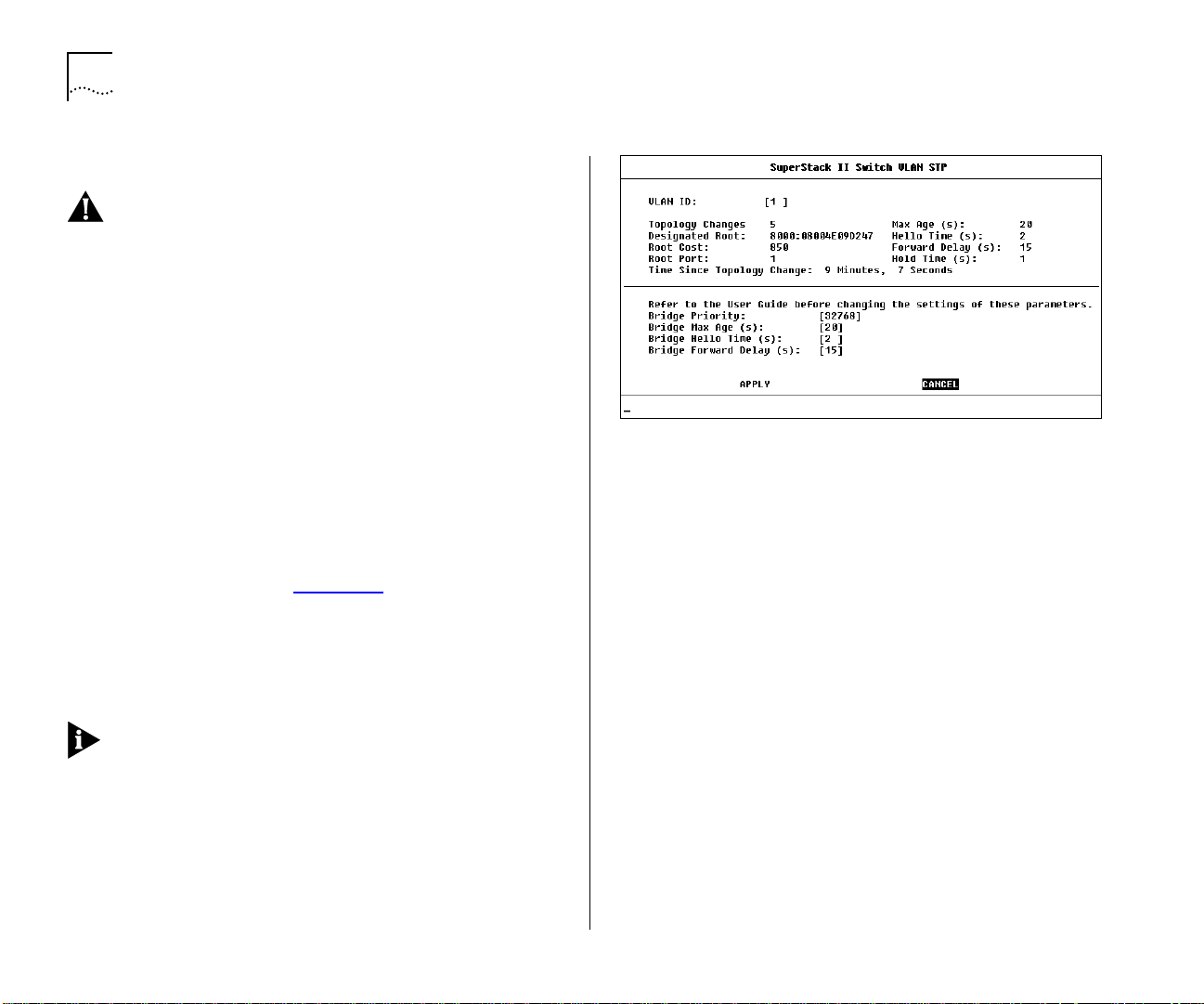
5-18 C
HAPTER
5: A
DVANCED MANAGEMENT
Configuring STP on the Switch
CAUTION: You should not configure any STP
parameters unless you have considerable knowledge and experience with STP.
Configuring the STP Parameters of VLANs
The Switch has a completely separate STP system for
each VLAN that you have specified. Each VLAN has
its own Root Bridge, Root Ports and BPDUs.
The VLAN STP screen allows you to set up and
manage an STP system for each VLAN on the
Switch. To access the VLAN STP screen:
1
From the Main Menu, select SWITCH MANAGEMENT. The Switch Management screen is displayed.
2
In the Management Level field, choose VLAN.
3
Choose the STP button. The VLAN STP screen is displayed, as shown in Figure 5-16
The VLAN STP screen shows the following:
VLAN ID
1 / 2 / 3 / ... 15
This field allows you to
specify the VLAN to be configured.
If you are using STP, you cannot use VLAN 16. Also,
if you are using AutoSelect VLAN Mode, you cannot
use VLAN 15. In these cases, the relevant VLANs are
used internally by the Switch and are therefore not
available.
Figure 5-16
VLAN STP screen
Max Age
6...40
This read-only field shows the
time (in seconds) that the Switch waits before trying
to re-configure the network. If the Switch has not
received a BPDU within the time specified in this
.
field, it will try to re-configure the network topology.
Designated Root
This read-only field shows the
Bridge Identifier of the designated Root Bridge.
1...10
Hello Time
This read-only field shows the
time delay, in seconds, between the transmission of
BPDUs from the Switch.
Root Cost
This read-only field shows the path cost
from the Switch to the Root Bridge.
Topology Changes
This read-only field shows the
number of network topology changes that have
occurred in the current VLAN.
Page 93

4...30
Forward Delay
This read-only field shows
the time (in seconds) that the ports on the Switch
spend in the listening and learning states. For more
information about these states, refer to “
Configur-
ing the STP Parameters of Ports” on page 5-20.
Root Port
This read-only field shows the Root Port
of the Switch.
Hold Time
This read-only field shows the shortest
time interval (in seconds) allowed between the
transmission of BPDUs.
Time Since Topology Change
This read-only field
shows the time interval since the last topology
change was detected.
Bridge Priority
0...65535
This field allows you to
specify the priority of the Switch. By changing the
priority of the Switch, you can make it more or less
likely to become the Root Bridge. The lower the
number, the more likely it is that the bridge will be
the Root Bridge. The default setting for this field is
65535.
Spanning Tree Protocol 5-19
The time must be greater than, or equal to, 2 x
(Hello Time + 1) and less than, or equal to,
2 x (Forward Delay – 1).
1...10
Bridge Hello Time
This field allows you to
specify the time delay, in seconds, between the
transmission of BPDUs from the Switch when it is
the Root Bridge. The default setting for this field is
2 seconds.
4...30
Bridge Forward Delay
This field allows you
to specify the time (in seconds) that the ports on
the Switch spend in the listening and learning states
when the Switch is the Root Bridge. The default setting is 15 seconds. For more information about
these states, refer to “
Configuring the STP Parame-
ters of Ports” on page 5-20.
This button applies any changes to the STP
APPLY
system.
Do not change the priority of the Switch unless
absolutely necessary.
6...40
Bridge Max Age
This field allows you to
specify the time (in seconds) that the Switch waits
before trying to re-configure the network when it is
the Root Bridge. If the Switch has not received a
BPDU within the time specified in this field, it will
try to re-configure the STP topology. The default setting for this field is 20 seconds.
Page 94

5-20 C
HAPTER
5: A
DVANCED MANAGEMENT
Configuring the STP Parameters of Ports
The Port STP screen allows you to set up and
manage the STP parameters of each port on the
Switch. To access the Port STP screen:
1
From the Main Menu, select SWITCH MANAGEMENT. The Switch Management screen is displayed.
2
In the Management Level field, choose Port.
3
In the Port ID field, enter the ID of the port to be
configured.
4
Choose the STP button. The Port STP screen is displayed, as shown in Figure 5-17
.
The screen shows the following:
Port ID
1 / 2 / 3 / ... 24 / 25 / 26 (3C16900A)
1 / 2 / 3 / ... 12 / 13 / 14 (3C16901A)
This read-only field shows the ID of the port to be
configured.
STP State
/ Forwarding
Disabled / Listening / Blocking / Learning
This read-only field shows the current
state of the port:
■
Disabled
— A port in this state does not forward
packets, and does not participate in STP operation.
■
Listening
— A port in this state is preparing to
forward packets, but has temporarily blocked to
prevent a loop. During the Listening state,
BPDUs are transmitted, received and processed.
Figure 5-17
■
Blocking
packets to prevent more than one active path
existing on the network. The port is included in
STP calculations, and BPDUs can be transmitted,
received and processed.
■
Learning
forward packets, but has temporarily blocked to
prevent a loop. During the Learning state, the
Switch learns the addresses of all error-free packets. The port is included in STP calculations, and
BPDUs can be transmitted, received and processed.
■
Forwarding
packets. BPDUs can also be received and processed.
Designated Port
of the Designated Bridge Port for the current port’s
segment.
Port STP screen
— A port in this state does not forward
— A port in this state is preparing to
— A port in this state can forward
This read-only field shows the ID
Page 95

Spanning Tree Protocol 5-21
Designated Root
This read-only field shows the
Bridge Identifier of the Root Bridge.
Designated Cost
This read-only field shows the
path cost from the Root Bridge to the Designated
Bridge Port for the current port’s segment.
Designated Bridge
This read-only field shows the
Bridge Identifier of the Designated Bridge for the
current port’s segment.
Fwd Transitions
This read-only field shows the
number of times that the current port has transitioned from the Learning state to the Forwarding
state.
Port Enable
Enable / Disable
This field allows you
to enable or disable the current port.
0...255
Priority
This field allows you to specify the
priority of the port. By changing the priority of the
port, you can make it more or less likely to become
the Root Port. The lower the number, the more
likely it is that the port will be the Root Port. The
default setting for this field is 128.
Fast Start
Enable / Disable
This field allows you to
specify whether the port goes directly to the Forwarding state when a device is connected to it. Set
this field to Enable if the port is directly connected
to an endstation. The default setting for this field is
Disable.
CAUTION:
If you set the Fast Start field to Enable
when the port is connected to multiple endstations,
loops may occur in your network.
Path Cost
0...65535
This field allows you to specify
the path cost of the port.
The Switch automatically assigns the default path
costs shown in Ta bl e 5- 1
on page 5-14. If you specify a new path cost in this field, this automatic
system is disabled, and you can only re-enable it by
initializing the Switch.
Page 96

5-22 C
RMON
Using the RMON (Remote Monitoring) capabilities of
your Switch allows network administrators to
improve their efficiency and reduce the load on their
network.
HAPTER
5: A
DVANCED MANAGEMENT
What is RMON?
RMON is the common abbreviation for the Remote
Monitoring MIB (Management Information Base), a
system defined by the IETF documents RFC 1271
and RFC 1757, which allows you to monitor LANs
remotely.
The following sections explain more about the
RMON concept and the RMON features supported
by the Switch.
You can only use the RMON features of the Switch
if you have an RMON management application,
such as the RMON application supplied with
3Com’s Transcend Enterprise Manager.
A typical RMON setup consists of two components:
■
The RMON probe
— An intelligent,
remotely-controlled device or software agent
that continually collects statistics about a LAN
segment or VLAN, and transfers the information
to a management workstation on request or
when a pre-defined threshold is crossed.
■
The management workstation
— Communicates with the RMON probe and collects the statistics from it. The workstation does not have to
be on the same network as the probe and can
manage the probe by in-band or out-of-band
connections.
Page 97

RMON 5-23
About the RMON Groups
The IETF define nine groups of Ethernet RMON statistics. This section describes these groups, and
details how they can be used.
Statistics
The Statistics group provides traffic and error statistics showing packets, bytes, broadcasts, multicasts
and errors on a LAN segment or VLAN.
Information from the Statistics group is used to
detect changes in traffic and error patterns in critical
areas of your network.
History
The History group provides historical views of network performance by taking periodic samples of
the counters supplied by the Statistics group. The
group features user-defined sample intervals and
bucket counters for complete customization of trend
analysis.
The group is useful for analysis of traffic patterns
and trends on a LAN segment or VLAN, and to
establish baseline information indicating normal
operating parameters.
Alarms
The Alarms group provides a versatile, general
mechanism for setting thresholds and sampling
intervals to generate events on any RMON variable.
Both rising and falling thresholds are supported, and
thresholds can be on the absolute value of a variable or its delta value. In addition, alarm thresholds
may be autocalibrated or set manually.
Alarms are used to inform you of a network performance problem and they can trigger automated
action responses through the Events group.
Hosts
The Hosts group specifies a table of traffic and
error statistics for each host on a LAN segment or
VLAN. Statistics include packets sent and received,
octets sent and received, as well as broadcasts, multicasts, and error packets sent.
The group supplies a simple discovery mechanism
listing all hosts that have transmitted. The next
group, Hosts Top N, requires implementation of the
Hosts group.
Hosts Top N
The Hosts Top N group extends the Hosts table by
providing sorted host statistics, such as the top 20
nodes sending packets or an ordered list of all
nodes according to the errors they sent over the last
24 hours.
Page 98

5-24 C
HAPTER
5: A
DVANCED MANAGEMENT
Matrix
The Matrix group shows the amount of traffic and
number of errors between pairs of devices on a LAN
segment or VLAN. For each pair, the Matrix group
maintains counters of the number of packets,
number of octets, and error packets between the
nodes.
The conversation matrix helps you to examine network statistics in more detail to discover who is talking to whom or if a particular PC is producing more
errors when communicating with its file server, for
example. Combined with Hosts Top N, this allows
you to view the busiest hosts and their primary conversation partners.
Filter
The Filter group provides a mechanism to instruct
the RMON probe to capture packets that match a
specific criterion or condition.
Capture
The Capture group allows you to create capture
buffers on the probe that can be requested and
uploaded to the management workstation for
decoding and presentation.
Events
The Events group provides you with the ability to
create entries in an event log and/or send SNMP
traps to the management workstation. Events can
originate from a crossed threshold on any RMON
variable. In addition to the standard five traps
required by SNMP (link up, link down, warm start,
cold start, and authentication failure), RMON adds
two more: rising threshold and falling threshold.
Effective use of the Events group saves you time;
rather than having to watch real-time graphs for
important occurrences, you can depend on the
Event group for notification. Through the SNMP
traps, events can trigger other actions providing a
mechanism for an automated response to certain
occurrences.
Page 99

RMON 5-25
Benefits of RMON
Using the RMON features of your Switch has three
main advantages:
It improves your efficiency
■
It allows you to manage your network in a more
■
proactive manner
It reduces the load on the network and the man-
■
agement workstation
How RMON Improves Your Efficiency
Using RMON probes allows you to remain at one
workstation and collect information from widely dispersed LAN segments or VLANs. This means that the
time taken to reach a problem site, set up equipment, and begin collecting information is largely
eliminated.
How RMON Allows Proactive Management
If they are configured correctly, RMON probes
deliver information before problems occur. This
means that you can take action before they impact
on users. In addition, probes record the behavior of
your network, so that you can analyze the causes of
problems.
How RMON Reduces the Traffic Load
Traditional network management involves a management workstation polling network devices at
regular intervals to gather statistics and identify
problems or trends. As network sizes and traffic
levels grow, this approach places a strain on the
management workstation and also generates large
amounts of traffic.
An RMON probe, however, autonomously looks at
the network on behalf of the management workstation without affecting the characteristics and performance of the network. The probe reports by
exception, which means that it only informs the
management workstation when the network has
entered an abnormal state.
Page 100

5-26 C
HAPTER
5: A
DVANCED MANAGEMENT
RMON and the Switch
RMON requires one probe per LAN segment, and
stand-alone RMON probes have traditionally been
expensive. Therefore, 3Com’s approach has been to
build an inexpensive RMON probe into the SmartAgent of each Switch. This allows RMON to be
widely deployed around the network without costing more than traditional network management.
A problem with stand-alone RMON probes is that
they are passive; able to monitor and report, but
nothing more. Placing probe functionality inside the
network device allows integration of RMON with
normal device management to allow proactive management.
For example, statistics can be related to individual
ports and the Switch can take autonomous actions
such as disabling a port (temporarily or permanently)
if errors on that port exceed a pre-defined threshold. Also, since a probe needs to be able to see all
traffic, a stand-alone probe has to be attached to a
non-secure port. Implementing RMON in the Switch
means all ports can have security features enabled.
RMON Features of the Switch
Tab le 5 -2 details the RMON support provided by
the Switch.
Table 5-2
RMON Group Support supplied by the Switch
Statistics
History
Alarms
RMON support supplied by the Switch
A new or initialized Switch has one Statistics session per port/VLAN.
A new or initialized Switch has three History sessions on the 100BASE-TX port, backbone port
and Default VLAN:
■
60-second intervals, 120 historical samples
stored
■
30-second intervals, 120 historical samples
stored
■
30-minute intervals, 96 historical samples
stored
Although up to 700 alarms can be defined for
the Switch, a new or initialized Switch has four
alarms defined for each port:
■
Bandwidth used
■
Broadcast bandwidth used
■
Percentage of packets forwarded
■
Errors per 10,000 packets
You can modify these alarms using an RMON
management application, but you cannot create
or delete them.
For more information about the alarms setup on
the Switch, refer to “About Alarm Actions” on
page 5-28
on page 5-29
and “About Default Alarm Settings”
.
 Loading...