

Page 1

T
OKEN
R
ING
S
WITCHING
R
About This Guide
M
ODULE INSTALLATION
For the LANplex 6000
This guide includes:
■
An inventory of items shipped with your LANplex 6000 module
■
An overview of the Token Ring Switching Module (TRSM)
Instructions for installing and replacing TRSM
■
■
A description of the TRSM’s components, including media options and
diagnostic LEDs
■
Pin-out information for the TRSM
Information on installing modules is also included in the
Getting Started
NOTE: Prior to installing the TRSM module, LANplex system software revision
6.0 or later must be installed.
CAUTION:
you must have the new LMM Plus installed in your system. To verify if you
have an LMM Plus installed check the module’s ejector tab to ensure it says
LMM+
.
guide.
In order to run software revision 5.0 or later on the LANplex 6000
G
UIDE
LANplex 6000
Audience
Taking Inventory
This guide is intended for trained technical personnel only.
Your package should contain the following items.
■
1 LANplex 6000 TRSM
1
LANplex 6000 Software Release Notes
■
■
1 disposable electrostatic discharge (ESD) wrist strap
■
Operational diskette(s) (UNIX and DOS)
MIB diskette(s) (UNIX and DOS)
■
Contact 3Com Customer Service Organization at 1-800-876-3266, option 2,
if any item is missing.
Page 2

2
TRSM Description
TRSM Description
TRSM Configurable
Bridge Modes
The Token Ring Switching Module (TRSM) is designed to add Token Ring
(TR) switching functionality to the LANplex 6000, providing the most cost
effective solution for introducing segmentation for today's Token Ring
networks, while allowing you to prepare for future higher bandwidth
requirements such as multimedia applications.
The TRSM has eight shielded RJ-45 token ring ports on the front of the
module and one FDDI backplane attachment which may be connected to
any of the three LANplex chassis FDDI backplanes. All eight token ring
switch ports support a full ring of 260 stations, with two of the ports able to
accommodate direct station attachment for dedicated bandwidth to file
servers and other critical resources. The shielded RJ-45 ports allow for
attachment via Type 1 STP or Type 3, 4, or 5 UTP copper cable. Each port is
independently configurable to support either 4 Mbps or 16 Mbps operation.
The TRSM is architected to support both source routed or transparent
traffic types in the following modes:
Transparent (T)
■
■
Source Routing (SR)
■
Source Routing-Transparent Bridge (SRT)
Transparent
The TRSM fully complies with the IEEE 802.1d bridging standard, which
means that the module:
■
Learns source addresses from packets transmitted by stations on LANs
attached to TRSM ports
Ages addresses of stations on attached LANs that have not transmitted a
■
packet for a prolonged time
■
Stores and forwards packets from one attached LAN to another
■
Uses the Spanning Tree protocol for loop detection
The TRSM automatically “learns” the MAC-layer addresses of the stations on
its attached networks, and then forwards packets to their appropriate
destinations. Packet forwarding is based on learned or statically configured
MAC addresses. The TRSM can learn up to 8192K addresses. Additional
addresses are learned as addresses are aged out. All addresses are stored in
Page 3

TRSM Description
3
nonvolatile RAM so they will survive a power loss or system initialization.
Source Routed traffic is not forwarded while in this mode.
Source Routing (SR)
In Source Routing (SR), the packet contains information in the Route
Information Field (RIF), which specifies the route the packet should follow in
order to reach its destination. Through the process of route discovery, the
packet determines various routes available and embeds this information as
Ring Numbers and Bridge Numbers within the RIF. The bridge compares the
RIF to its configured Bridge Numbers and Ring Numbers for each port and
forwards the packet if appropriate. The TRSM utilizes one hop between any
two ports on the module.
For Spanning Tree, the network mesh topology is reduced to a single path
utilizing IEEE 802.1d Spanning Tree.
Transparent traffic is not forwarded while in this mode.
TRSM Configurable
Protocol Translation
Modes
Source Routing Transparent (SRT)
The Source Routing-Transparent (SRT) operation complies with the 802.1d
standard which provides bridging for both Source Routing and non-Source
Routing protocols. It uses the Route Information Indicator to differentiate
between SR and non-SR packets and applies the appropriate bridging
method on each packet received.
To configure the Bridging mode, see Chapter 11:
the
LANplex 6000 Administration Console User Guide. N
Administering the Bridge
in
Protocol addresses on Token Ring are defined in non-canonical format while
FDDI is defined in canonical format. For a workstation on Token Ring to
communicate with a server on FDDI, it is necessary to reformat or translate
these embedded protocol address. The TRSM supports translation between
Token Ring and FDDI for the following protocols: IP, IPX, NetBIOS, and SNA.
Translation is not necessary if FDDI is only used as a transport media
between TRSMs. Since this feature may degrade performance, it is
recommended that you disable the translation feature when FDDI is used
solely as a transport media.
Page 4

4
TRSM Installation
TRSM Installation
Safety Information
This section describes the following:
Module safety information
■
■
Installation information
LED activity during installation
■
Pin-out information
■
Information on installing modules is also included in the
Getting Started
guide.
LANplex 6000
Electrostatic discharge (ESD) damage occurs when the module is improperly
handled. ESD can damage components on a module, causing complete or
intermittent failures.
To prevent ESD-related damage, handle the module in the following
manner:
Always wear the ESD wrist strap provided with the module, ensuring that it
■
makes good skin contact and that the alligator clip is connected to a
suitable ground. See Figure 3
■
Keep the module in its antistatic shielded bag until you are ready to
on page 7.
install it.
Prior to Installation
Read if installing in
an empty slot
Do not touch the components, pins, leads, or solder connections.
■
Always handle the module by its edges.
■
Additionally, you should cover every empty slot with a blank faceplate to
protect the system from dust or other foreign substances, and to ensure
proper system cooling.
Before you install your new module, follow the appropriate pre-installation
instructions below:
Your LANplex system is shipped with no modules installed and with
protective faceplates covering the installation slots. Initial installation
requires that you remove the protective faceplate covering the selected
installation slot prior to installing the option module.
Page 5
TRSM Installation
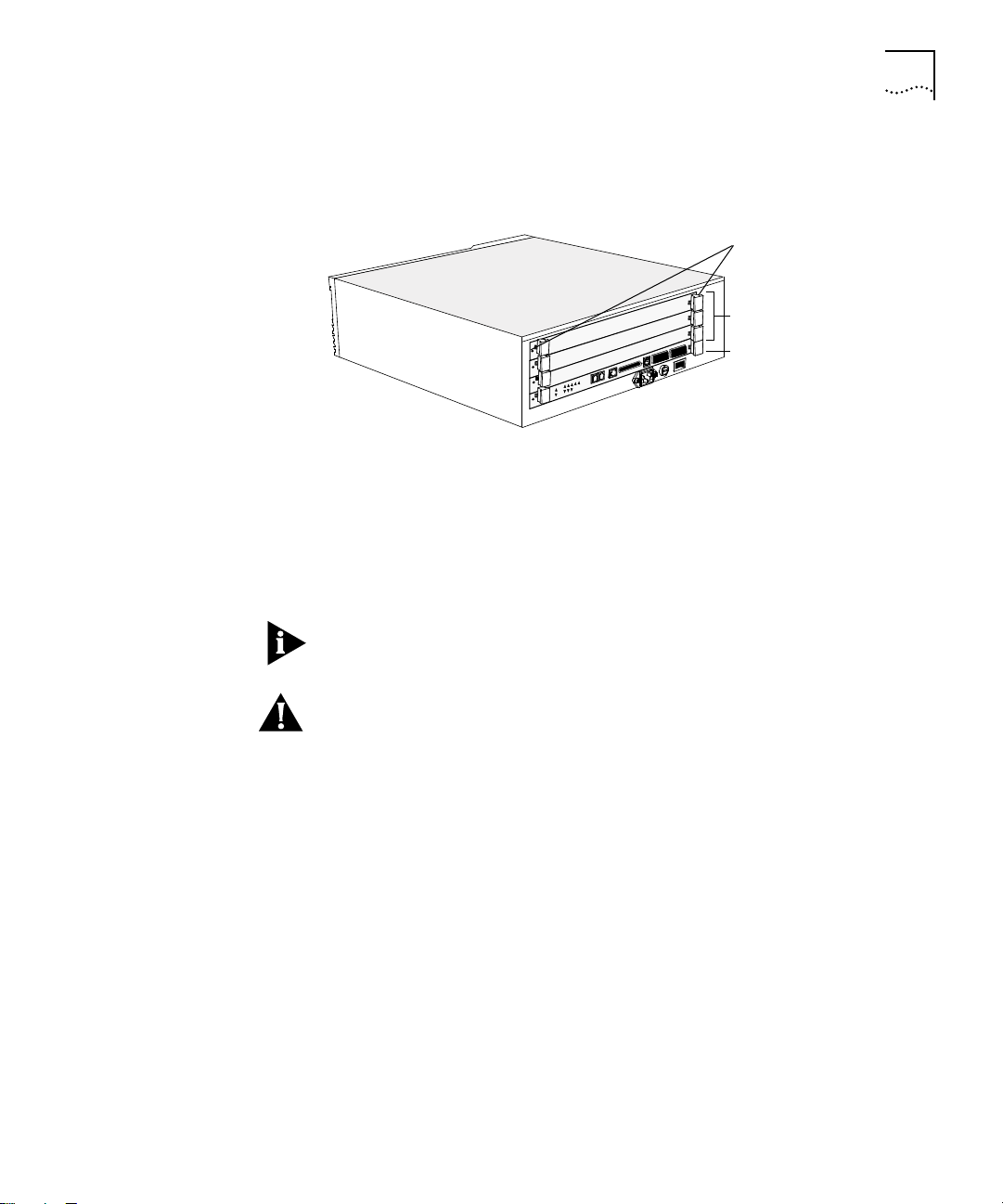
To remove the faceplate:
1
Unscrew the securing screws on the module’s faceplate. See Figure 1.
Captive screws
Captive screws
Blank faceplates
Blank faceplates
LMM+ in slot 1
LMM+ in slot 1
5
Read if replacing
a TRSM
Figure 1
2
Pull the faceplate away from the system.
LANplex 6004 with Blank Faceplates
You can replace a module while the system is powered on. Replacing the
module requires that you remove the attached cables from the module’s
ports prior to installing the new module.
NOTE:
Ensure that there is a record of where the cables are attached so that
you can correctly re-connect them to the new module.
CAUTION:
Inserting and extracting a TRSM erases all information stored in
NVRAM on the TRSM. Before removing the installed TRSM, save all
nonvolatile data using the NV data save functionality on the system’s
Administration Console. This information can be restored using the NV
restore functionality. See the LANplex 6000 Administration Console User
Guide for information on saving, restoring, and resetting nonvolatile data.
Inserting and extracting a module will cause a warm system reboot.
To remove a module:
1
Discharge yourself of static electricity by placing the ESD wrist strap on your
wrist and clipping the alligator clip to the mounting screw located next to
the black ground symbol on the system’s right mounting bracket. See
Figure 3. If your system does not have mounting brackets, touch the rear
panel.
2
Disconnect the cables from the module’s ports.
3
Unscrew the securing screws on the module’s faceplate. See Figure 1.
Page 6

6
TRSM Installation
4
Grasp the inject/eject handles of the module and push them outward as
shown in Figure 2.
Module faceplate
Module faceplate
Installing the TRSM
Figure 2
5
Remove the module from the system.
6
Place the module in its antistatic bag.
Handles in Outward Position
The installation procedure takes only a few minutes to complete. You need
a small, flat-blade screwdriver.
NOTE:
Only the LMM may be inserted in slot one of the LANplex system. The
system will not operate if any other module is inserted into slot one. Slot one
of the LANplex 6004 is the bottom slot, and slot one of the LANplex 6012 is
the first slot on the left.
To install the TRSM in an empty slot in the LANplex system, perform the
following steps:
1
Discharge yourself of static electricity by placing the ESD wrist strap on your
wrist and clipping the alligator clip to the mounting screw located next to
the black ground symbol on the system’s right mounting bracket. See
Figure 3. If your system does not have mounting brackets, touch the rear
panel.
Page 7

TRSM Installation
11
12
13
14
15
16
5
6
7
8
4
6
5
4
6
5
RX
TX
RX
TX
RX
TX
RX
A/M
B/M
4
5
Ground symbol
Mounting
screw hole
7
Figure 3
2
Remove the TRSM from its antistatic bag.
3
Make sure that the inject handles are in the outward position. See Figure 4.
Figure 4
Ground Symbol for Static Discharge
Module faceplate
Module faceplate
Handles in Outward Position
4
Orient the TRSM to insert it into the LANplex system. For a LANplex 6012
system, orient the module so that its labeling is upright. For a LANplex 6004
system, the module’s labeling should be on your left.
Page 8

8
TRSM Installation
WARNING:
If the system is powered on when you are installing a module,
do not insert any metal objects, such as a screwdriver or a finger with
jewelry, in the open slot. This could cause burns or other bodily harm, as well
as system damage.
5
Direct the module into the chassis by placing it between the guides of the
selected slot and sliding the module until it stops. The module stops sliding
when the inject handles make contact with the front of the chassis.
Figure 5 shows a TRSM being installed in a 6012 system. Figure 6 shows a
TRSM being installed in a 6004 system.
LMM in slot 1
R
LMM
Pwr/Unseat
Err
Port Status
1
INS
2
4
3
5
Temp
Run
TRSM
Pwr/Unseat
Serial
Ports
Ethernet
Optical
Bypass
Err
1
5
2
6
3
7
1
4
8
2
1
5
2
6
3
7
4
8
3a
2
1
3b
1
2
4
3
A/M
B/M
4
5
5
6
7
8
TRSM
LANplex 6012
Figure 5
Guiding an TRSM Module into a LANplex 6012
Page 9

TRSM Installation
9
LMM in slot 1
TRSM
Figure 6
6
Inject the TRSM into the chassis.
■
Guiding an TRSM Module into a LANplex 6004
If the system is powered on, when the
TRSM
Power/Unseat
LED on the
panel’s faceplate is yellow, inject the TRSM into the chassis by grabbing
both ejector/injector handles and simultaneously push them inward. See
Figure 7.
If the system is not powered on, once you feel a slight resistance, inject
■
the TRSM into the chassis.
7
Relocate the inject handles back to their center position by gently pushing
them inward. See Figure 7.
This locks the TRSM into the chassis. The
Power/Unseat
LED lights green
when the TRSM is seated.
Page 10

10
TRSM Installation
Module faceplate
Module faceplate
Figure 7
NOTE:
Handles in Inward (Inject) Position
Do not push the handles outside the center position or you will eject
the module. These handles act as “ejectors” when pushed outward and
“injectors” when pushed inward.
8
See the following section on “LED Activity” to verify that the TRSM has been
properly installed.
9
Tighten the TRSM’s securing screws using a flat-blade screwdriver.
Page 11

TRSM Installation
11
LED Activity
If the system is powered on, you can verify that your module is properly
installed by observing its LEDs. Follow the troubleshooting suggestions
below if LED activity is not normal.
Normal LED Activity
The following LED activity is normal during installation:
The
■
Power/Unseat
LED lights yellow briefly when the module is inserted far
enough into the chassis to use the inject/eject handles.
■
The
Err
LED lights yellow temporarily after insertion while the module runs
diagnostics.
The
■
Power/Unseat
LED lights green, indicating that the module is
powered on.
Once you have completed the installation procedure, only the green
Power/Unseat
LED should remain lit.
Troubleshooting
If LED activity is not normal, check the troubleshooting suggestions
listed below.
If the
■
Power/Unseat
LED remains yellow, the module is not fully seated in
the chassis. Eject and re-insert the module as described in the installation
procedure starting on page 6.
■ If the Err LED remains yellow, contact 3Com Technical Support for additional
assistance.
■ If the Power/Unseat LED does not light green when the module is
powered on, contact 3Com Technical Support for assistance.
NOTE: For 3Com Technical Support information, see Appendix B: Technical
Support in the LANplex 6000 Getting Started guide.
Page 12

12 TRSM Components
TRSM Components
The main components of the TRSM include board status LEDs, eight port
status LEDs, eight port speed LEDs, two port mode LEDs, and eight Token
Ring shielded RJ-45 connectors. Figure 8 shows the front panel of the TRSM.
TRSM
Pwr/Unseat
Port Status
1
2
3
4
Port Speed
1
2
3
4
Hub Port
1
Securing screw
Inject/eject handle
Err
Module status LEDs
5
6
7
Port status LEDs
8
5
6
7
Port speed LEDs
8
2
Port mode LEDs
Ports 1 and 2
1
Station/lobe switchable ports
2
3
Ports 1-4
4
5
6
Ports 5-8
7
8
Inject/eject handle
Securing screw
Figure 8 TRSM Option Module
Page 13

TRSM Components 13
Status LEDs Each TRSM contains two Module Status LEDs and eight Port Status LEDs.
Depending on the condition, each LED is either green or yellow. Table 1
describes these LEDs.
Table 1 FDDI/Ethernet Switching Module LEDs
LEDs Name Color Description
Module
Status
Port
Status
Pwr/Unseat Green
Yellow
Err
(Error)
Port Status
1 - 8
Port Speed
1 - 8
Port Mode
1 - 2
Yellow Indicates either that an error has
Green
Yellow
Green
Yellow
Yellow
Green
Indicates that the module is powered on
Indicates that the module is not fully
plugged into the backplane
occurred or that the module has failed a
diagnostic procedure
Indicates that the associated port is active
Indicates that an error condition has
occurred with the associated port or that
the port is disabled
Indicates that the port is running at
16Mbps
Indicates that the port is running at
4Mbps
Indicates that the ports are configured as
lobes and can accept an external station
connection
Indicates that a station is attached to the
lobe port
Page 14

14 Pin Assignments
Pin Assignments Table 2 provides the pin assignments for the TRSM’s eight (RJ-45) ports in
station mode. Table 3 provides the pin assignments for ports 1 and 2 when
configured as lobes.
Table 2 Station Mode TRSM (RJ-45) Pin Assignments
Pin No. Signal Description
1 Not used
2 Not used
3 TX- Transmit-
4 RX+ Receive+
5 RX- Receive-
6 TX+ Transmit+
7 Not used
8 Not used
Table 3 Lobe Mode TRSM (RJ-45) Pin Assignments
Pin No. Signal Description
1 Not used
2 Not used
3 RX- Receive-
4 TX+ Transmit+
5 TX- Transmit-
6 RX+ Receive+
7 Not used
8 Not used
Page 15

Documentation Comments 15
Documentation Comments
Example:
Your suggestions are very important to us and will help make LANplex
documentation more useful to you. Please email comments about this
guide to: sdtechpubs_comments@3Mail.3Com.com
Please include the following information when commenting:
■ Document title
■ Document part number (listed on back cover of document)
■ Page number (if appropriate)
■ LANplex 6000 Planning Your Site
■ Part No. 801-00251-000
■ Page 2-5 (chapter 2, page 5)
Page 16

16
3Com Corporation
5400 Bayfront Pla a
Santa Clara, California
5052- 154
© 3Com Corporation, 1995. All rights reserved. No part of this documentation may be reproduced in any form
or by any means or used to make any derivative work (such as translation, transformation, or adaptation)
without permission from 3Com Corporation.
3Com Corporation reserves the right to revise this documentation and to make changes in content from time
to time without obligation on the part of 3Com Corporation to provide notification of such revision or change.
3Com Corporation provides this documentation without warranty of any kind, either implied or expressed,
including, but not limited to, the implied warranties of merchantability and fitness for a particular purpose.
3Com may make improvements or changes in the product(s) and/or the program(s) described in this
documentation at any time.
3Com and LANplex are registered trademarks of 3Com Corporation. 3Com registered trademarks are registered
in the United States, and may or may not be registered in other countries. Other brand and product names may
be registered trademarks or trademarks of their respective holders.
Part No. 801-00194-000
Published December 1995
Revision 01
 Loading...