

Page 1

V
ADSL Ethernet & USB Combo Router
• Product warranty does not apply to damage caused by lightning, power surges or wrong voltage usage.
• This product is for use only in UL Listed computers.
Quick Guide
ersion 1.1
Page 2

Lynx L-510
Quick Guide
Contents
Declaration Of Conformity ...........................................................................3
Countries of Operation and Conditions of Use in the European Community...................3
Radio Frequency Interference Warnings & Instructions..................................................4
RF Exposure...................................................................................................................4
Introduction..................................................................................................5
Minimum System Requirements..................................................................5
Lynx L-510 Package....................................................................................6
Lynx L-510 Overview...................................................................................7
Typical Wireless-G Router Connection........................................................9
STEP 1: Connecting the Lynx L-510 to Your Computer................................................10
Step 1.1 Connecting the Lynx L-510..........................................................................10
1.1.2 (a) Connecting to the Ethernet ............................................................................10
1.1.2 (b) Connecting to the USB ..................................................................................11
Step 1.2 Connecting to the ADSL Line..........................................................................11
1.2.1 (a) To connect to the ADSL line......................................................................12
1.2.1 (b) To connect to the ADSL line and Telephone Set............................................12
Step 1.3 Connecting to the Power Outlet...................................................................13
Step 1.4 Powering On................................................................................................14
STEP 2: Configuring Your Ethernet Network Card/ Installing your USB
Device........................................................................................................15
Step 2.1: Configuring Your Ethernet Network Card......................................................15
2.1.1 For Windows® 98 Second Edition / Windows® Me..........................................15
2.1.2 For Windows® 2000 / Windows® XP..............................................................16
Step 2.2: Installing the USB Device Driver....................................................................17
2.2.1 Installing the USB Device Driver for Windows® (98/SE/Me/2000/XP)............17
STEP 3: Configuring Your Internet Browser.............................................21
Step 3.1: Microsoft® Internet Explorer™ (based on IE 5.5)....................................21
Step 3.2: Netscape® Navigator...............................................................................21
Modify the Settings of your Modem ...........................................................22
Maintenance..............................................................................................23
2
Page 3
Lynx L-510
Quick Guide
Declaration Of Conformity
Marking by the above symbol indicates compliance with the Essential Requirements of
the R&TTE Directive of the European Union (1999/5/EC). This equipment meets the
following conformance standards:
EN300 328, EN301 489-17, EN60950
Countries of Operation and Conditions of Use in the European
Community
This device is intends to be operated in all countries of the European Community.
Requirement is for indoors vs. outdoors operation, license requirements and allowed
channels of operation apply in some countries as described in this document.
Note: The user must use the configuration utility provided with this product to
check the current channel of operation and confirm that the devices operating
in conformance with the spectrum usage rules for the European Community
countries as described below.
If operation is occurring outside of the allowable channels as indicated in this guide,
then the user must cease operating the product and consult with the local technical
support staff responsible for the wireless network.
This device may be operated indoors or outdoors in all countries of the European
Community using the 2.4GHz band: Channels 1 – 13, except where noted below:
− In Italy the end-user must apply for a license from the national spectrum authority
to operate this device outdoors.
− In France outdoor operation is only permitted using the 2.4 – 2.454 GHz band:
Channels 1 – 7.
3
Page 4

Lynx L-510
Quick Guide
Radio Frequency Interference Warnings & Instructions
(FCC ID: I38-DSL600EWR)
This equipment has been tested and found to comply with the limits for a Class B digital
device, pursuant to Part 15 of the FCC Rules. These limits are designed to provide
reasonable protection against harmful interference in a residential installation. This
equipment uses and can radiate radio frequency energy and, if not installed and used in
accordance with the instructions, may cause harmful interference to radio
communications. However, there is no guarantee that interference will not occur in a
particular installation. If this equipment does cause harmful interference to radio or
television reception, which can be determined by turning the equipment off and on, the
user is encouraged to try to correct the interference by one or more of the following
methods:
− Reorient or relocate the receiving antenna
− Increase the separation between the equipment and the receiver
− Connect the equipment into an electrical outlet on a circuit different from that
which the radio receiver is connected
− Consult the dealer or an experienced radio/TV technician for help.
Modifications made to the product, unless expressly approved by the party responsible,
could void the user’s right to operate the equipment.
RF Exposure
This device has been tested and complies with FCC RF Exposure (SAR) limits in typical
laptop computer configurations and this device can be used in desktop or laptop
computers with side mounted PCMCIA slots, which can provide 1 cm separation
distance from the antenna to the body of the user or a nearby person. Thin laptop
computers may need special attention to maintain antenna spacing while operating.
This device cannot be used with handheld PDAs (personal digital assistants). Use in
other configurations may not ensure compliance with FCC RF exposure guidelines.
This device and its antenna must not be co-located or operate in conjunction with
another antenna or transmitter.
4
Page 5

Lynx L-510
Quick Guide
Introduction
Thank you on your purchase of the Lynx L-510! The Lynx L-510 provides you with a
high-speed broadband Internet connection using your existing phone line that at the
same time allows you to make phone calls.
The Lynx L-510 can be connected to any computer/notebook with a USB Port or 10/100
Base-T Ethernet card for wired connection or an IEEE 802.11b/g Wireless adapter. For
multiple user connections, you may connect your computers/notebooks to both the
Ethernet Ports or through the Wireless adapter. The Ethernet ports have Auto
MDI/MDIX feature which can allows both cross or straight UTP cable to be utilized. The
Lynx L-510 has an in-built IEEE802.11g Wireless LAN Access Point for wireless
connectivity.
This documentation assumes that there is an Ethernet card or a wireless adapter on
your computer.
Minimum System Requirements
• Pentium
• A CD-ROM Drive
• Ethernet card installed with TCP/IP Protocol (required only if you are connecting to
the ETHERNET port of your DSL Router)
• USB port (required by if you are connecting to the USB Port of your ADSL Router)
• IEEE 802.11b/g Wireless adapter (Required if you are connecting to the Wireless
Access Point of the router)
• Host Operating Systems support for USB:
• OS independent for Ethernet
®
MMX 233MHz
Windows® 98 Second Edition
Windows® 2000
Windows® Me
Windows® XP
• Web Browser support:
Microsoft Internet Explorer 4.0 (or later versions)
Netscape® Navigator 3.02 (or later versions)
5
Page 6
Lynx L-510
Quick Guide
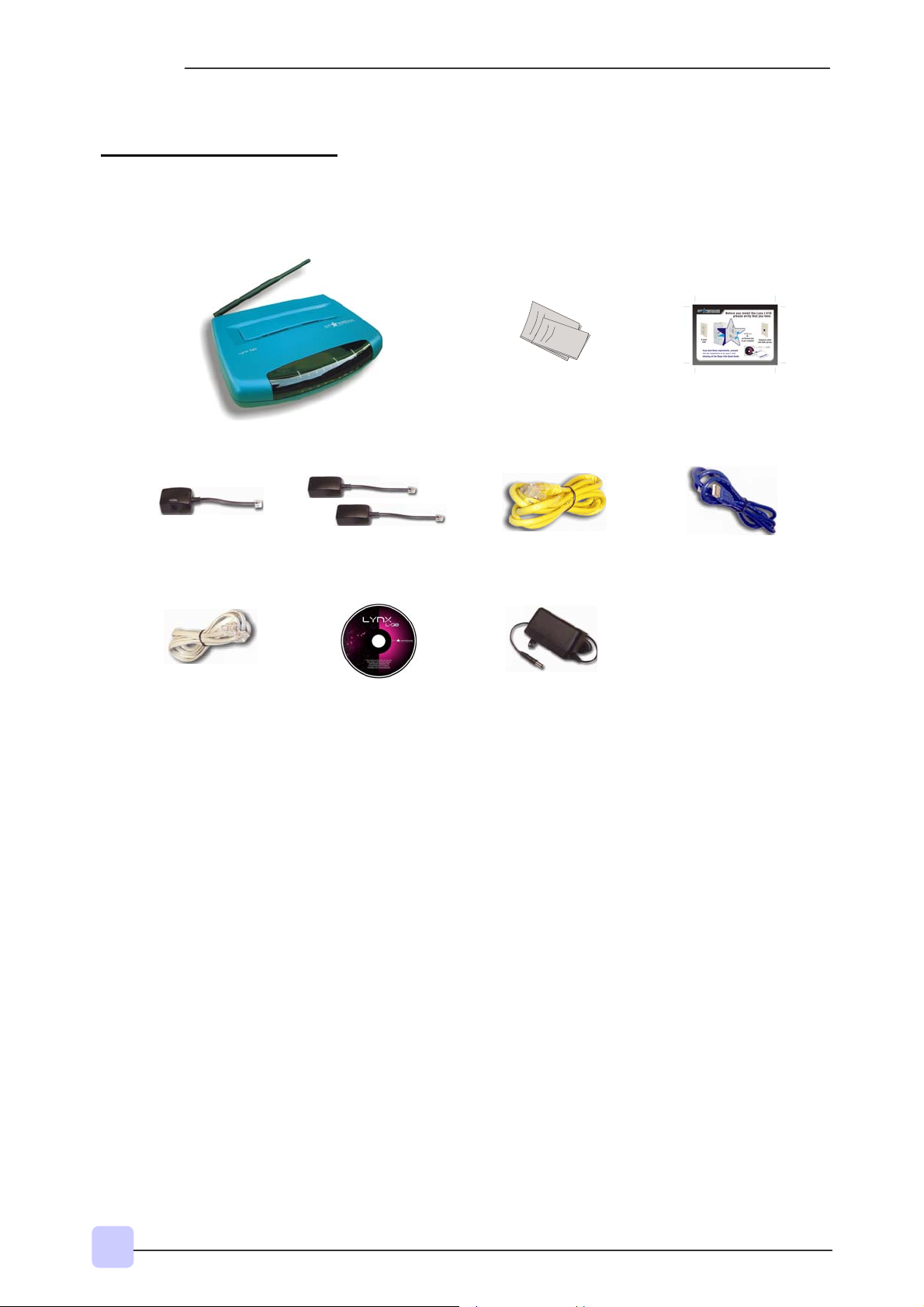
Lynx L-510 Package
For any missing items, please contact your dealer immediately.
1 POTS Splitter
1 Telephone Cable
(RJ-11)
1 Modem Lynx L-510
3
1
2 In-line Filters3
1 Installation CD
1 Quick Guide
1 Ethernet Cable
(Cat 5 UTP Straight
Ethernet Network
Cable)
1 Power Adapter
(DC 9V)2
1 Pre-installation
requirements Guide
1 USB Cable
1 The telephone extension cable used for this Lynx L-510 is a UL Listed Communication Circuit
Accessory, minimum 26AWG.
2 This product is intended to be supplied by a UL Listed Direct Plug-In Power Unit marked "Class 2" and
rated Input: 120VAC, 50-60Hz, 26W, Output: 9Vdc, 1A Only. Different countries are bundled with
different types of power adapter. The above illustration is only a representative.
3 Depending on your country of purchase, your package may or may not come with a POTS Splitter and
or 2 In-Line Filters. The POTS Splitter is required if you are connecting a Telephone Set to the Ethernet
Modem. The In-line Filter is required to avoid the noise produced by the telephone equipment. Please
refer to Step 1.2 - Connecting to the ADSL Line for details. POTS-Splitter and In-Line Filters can also
be purchased from your dealer.
6
Page 7

Lynx L-510 Overview
Front Indicators
1 2 3 4 5 6
1 POWER
Lynx L-510
Quick Guide
Lights up when power is supplied to the ADSL Router.
2 ETHERNET (E1 ~ E4)
Lights up when the Ethernet cable is properly connected from your ADSL Router to the
Ethernet Card. It flickers when the ADSL is transmitting/receiving data.
3 WIRELESS
Flickers when the Wireless LAN is operational.
4 USB
Lights up when the USB cable is properly connected from your ADSL Router to the
USB slot. Lights Off when the USB cable is not connected or it is properly disconnected.
5 DSL
LED lights off when no Telephone jack (RJ-11) is connected. Flickers when the ADSL
Router is trying to establish a connection with the ADSL Service Provider (Training).
Steady Green LED lights up when the ADSL connection is established.
6 Internet
Green LED lights up when the PPP connection is established. Lights off when no PPP
connection.
7
Page 8
Lynx L-510
Quick Guide
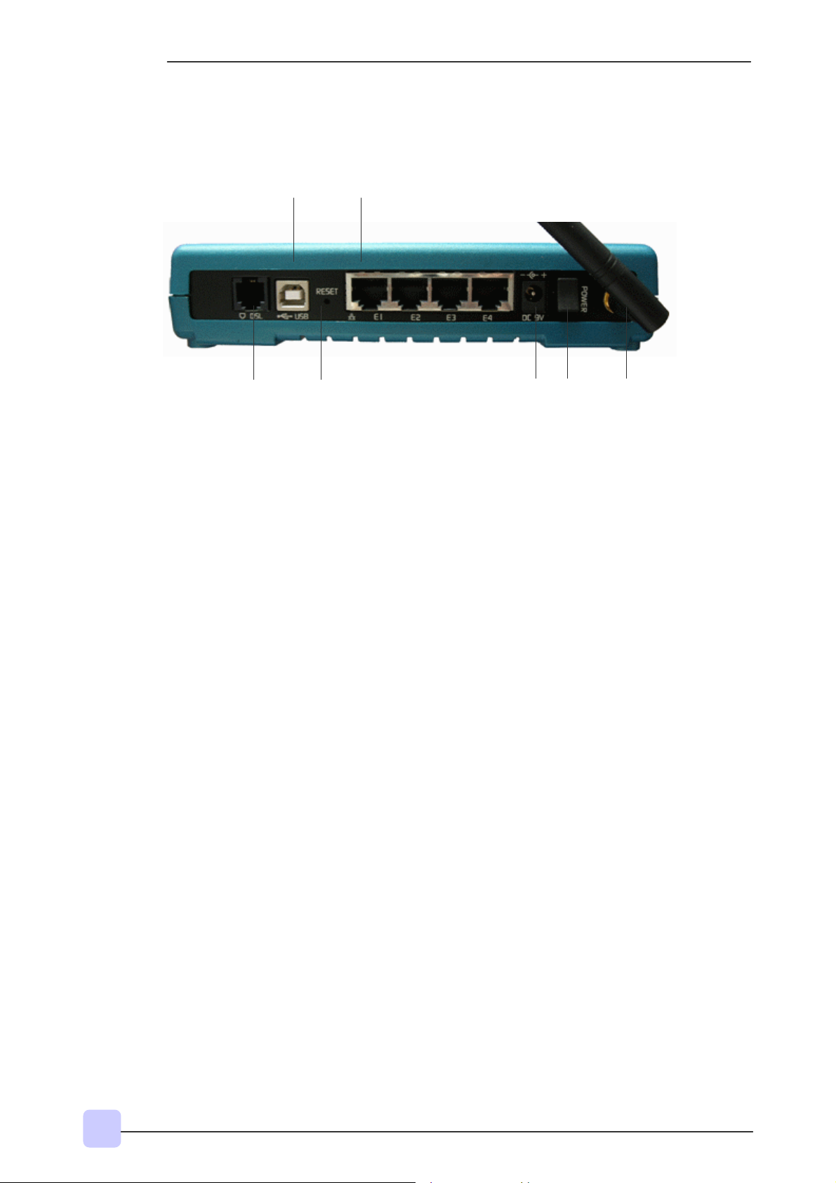
Back Panel
2 4
1 3 5 6 7
1 DSL
Connect the telephone jack (RJ-11) to your Telephone Wall Socket (DSL line).
2 USB
Connect the USB jack to your PC’s USB slot.
3 RESET
To reset your ADSL Router to factory default settings (all customized settings that you
have saved will be lost!). To reset the ADSL Router, simply press the reset button for
about 10 seconds.
4 ETHERNET (E1-E4)
10/100 Base-T Auto-MDI/MDIX Ethernet jack (RJ-45) to connect to your PC’s Ethernet
Network card or Ethernet Hub / Switch.
5 DC 9V
To connect to the Power Adapter that comes with your package.
6 POWER SWITCH
To power on or off the modem. Push downwards to switch ON and lift upwards to OFF.
7 RF Antenna
180° 2.4Ghz Wireless Antenna.
8
Page 9

Lynx L-510
Quick Guide
Typical Wireless-G Router Connection
Fig 1-4 below shows up to 4 PCs connections.
Computers with
Wireless Cards
Lynx L-510
Computers
with Ethernet
Network Cards
Figure 1- 1 : 4 PCs Connection Diagram
To connect to more than 4 computers/notebooks, you may further expand one of the
Ethernet Ports via an Ethernet Hub/Switch. For details on how to connect to the
Ethernet Switch/Hub, please refer to the documentation that comes with the unit.
9
Page 10

Lynx L-510
Quick Guide
Step 1:
Connecting the Lynx L-510 to Your Computer
! Power off your Computer/Notebook or/and any connected devices before
connecting to the Lynx L-510!
To connect to your Lynx L-510, you need to have either an Ethernet Port or a USB
Port present on your computer/Notebook.
Step 1.1 Connecting the Lynx L-510
• If an Ethernet Port is present, please proceed to section 1.1.2(a) Connecting to the
Ethernet.
• If an Ethernet Port is not present, locate the USB Port on your
Computer/Notebook and proceed to section 1.1.2 (b) Connecting to the USB.
1.1.2 (a) Connecting to the Ethernet
Ethernet Network Cable
Ethernet Port
Ethernet Port
Back view of a Computer Back view of the Lynx L-510
Note: This connection is not required if you are connecting to an Ethernet Switch/Hub
for multiple-users connection.
You may now proceed to Step 1.2.
10
Page 11

L
1.1.2 (b) Connecting to the USB
Lynx L-510
Quick Guide
USB Cable
USB Port
USB Port
Back view of a Computer Back view of the Lynx
You may now proceed to Step 1.2.
-510
Step 1.2 Connecting to the ADSL Line
To connect the Lynx L-510 to the ADSL line, carriy out Step 1.2(a).
To connect the Lynx L-510 to the ADSL line and a Telephone Set, carry out Step
1.2(b).
11
Page 12

Lynx L-510
Quick Guide
1.2.1 (a) To connect to the ADSL line
Telephone Cable
ADSL Port
Back view of the Lynx L-510 Telephone Outlet
1.2.1 (b) To connect to the ADSL line and Telephone Set
You must install the POTS Splitter if you need to have a phone near the modem.
The POTS Splitter (with built-in Microfilter) is a device that allows you to connect both
your Telephone cable and Telephone Set to the same Telephone Wall Socket. The
device at the same time helps to eliminate background noise on the telephone line,
ensuring the best possible phone performance.
Please follow the following steps to install the Splitter:
1. Connect your phone to the jack PHONE of the Splitter.
2. Connect the DSL modem to the jack MODEM of the Splitter.
3. Connect the jack WALL to the telephone outlet.
12
Page 13

L
T
L
Lynx L-510
Quick Guide
Splitter
Phone
Back view of the Lynx
Step 1.3 Connecting to the Power Outlet
elephone Outlet
ADSL Port
-510
Connect your Lynx L-510 to the Power Outlet via the Power adapter (that comes with
your Lynx L-510 package).
DC Port
Power Outlet
Back view of the Lynx
-510
13
Page 14

Lynx L-510
Quick Guide
Step 1.4 Powering On
Power on the Power Outlet that is connected to your Lynx L-510.
Power on your Computer(s)/Notebook(s).
Please insert your Lynx L-510 installation CD.
Please proceed to Step 2.
14
Page 15

y
K
Lynx L-510
Quick Guide
Step 2:
Configuring Your Ethernet Network Card/ Installing
your USB Device
! If your computer/notebook is connected to the Ethernet Port of the Lynx L-510,
proceed with section 2.1.
! If your computer/notebook is connected to the USB Port of the Lynx L-510, proceed
with section 2.2.
! If your computer/notebooks are connected to both the Ethernet Port and USB Port of
your Lynx L-510, please proceed with both sections 2.1 and 2.2.
Step 2.1: Configuring Your Ethernet Network Card
1. Proceed with this section ONLY if your computer/notebook is connected to the Ethernet Port of
your ADSL Router.
2.1.1 For Windows® 98 Second Edition / Windows® Me
2. The following illustrated screen shots serve only as examples. For any dissimilarity, please follow
closel
the instructions prompted on yourComputer.
i From your Windows desktop, right-click on the Network Neighborhood icon.
Select Properties.
iiii From the Configuration tab, select TCP/IP-> xxx where xxx refers to the model
of your Ethernet Card that is connected to your Lynx L-510.
Click Properties.
(This screen shot uses 3Com
EtherLink Ethernet card model as an
example).
iii Click the IP Address tab.
Click the option Obtain an IP
address automatically and click
O
to save the settings.
15
Page 16

Lynx L-510
Quick Guide
Ensure that your Lynx L-510 is powered on.
Restart your system. Proceed to Step 3.
2.1.2 For Windows® 2000 / Windows® XP
i Windows® 2000:
a) From your Windows desktop, right-click on the icon My Network Places and
select Properties.
b) At the Network and Dial-up Connections window, right-click on the Local
Area Connection icon and select Properties.
Windows
(Instructions are based on default Start menu option)
a) From your Windows desktop, click Start > All Programs > Accessories >
Communications > Network Connections.
b) Right-click on the Local Area Connection icon that reflects the model of your
Ethernet Card that is connected to your Lynx L-510 and click Properties.
®
XP:
ii Ensure that the field Connect Using indicates the model of your Ethernet Card that is
connected to your Lynx L-510.
(This is important especially if you have more than one Local Area Connection icons
displayed at the Network and Dial-up Connections/Network Connections window.
Ensure that you have selected the correct one.)
Select Internet Protocol (TCP/IP) and click Properties.
(This screen shot uses 3Com
EtherLink Ethernet card model as an
example).
iii. Select the option Obtain an IP address
automatically and click OK.
Click OK again to close.
16
Page 17

y by y
Lynx L-510
Quick Guide
Ensure that your Lynx L-510 is powered on.
Restart your system. Proceed to Step 3.
Step 2.2: Installing the USB Device Driver
1. Proceed with this section ONLY if your computer/notebook is connected to the USB Port of
your ADSL Router!
2. The following screen shots illustrated serve only as examples. For any dissimilarity, please
follow closely the instructions prompted on your Computer/Notebook.
3. For Windows®98 Second Edition users, you may be prompted for your Windows CD-ROM.
Have it read
our side.
2.2.1 Installing the USB Device Driver for Windows® (98/SE/Me/2000/XP)
i. Power on your computer to start Windows.
ii. Place the Installation CD into your CD-ROM Drive. The following screen will
appear.
iii. Select Install USB Driver
iv. The following screen will appear. Click Next.
17
Page 18

Lynx L-510
Quick Guide
v. Read carefully the License Agreement. If you agree, select the option I Agree and
click Next.
vi. The following screen will appear. Please make sure that the modem is not
connected to the computer. Click Next.
18
Page 19

Lynx L-510
Quick Guide
vii. Select the Installation Folder and click Next.
viii. Click Next to proceed installation with indicated driver.
19
Page 20

Lynx L-510
Quick Guide
ix. Click Next to complete the USB Driver installation
Depending on your system configurations, you may be prompted for your windows CD-ROM during
installation. At the prompt, replace the Installation CD in your CD-ROM Drive with your Windows
CD-ROM and click OK.
At the Copying Files dialog box, enter the path of your Windows CD-ROM and click OK.
20
Page 21

Lynx L-510
Quick Guide
Step 3:
Configuring Your Internet Browser
Step 3.1: Microsoft® Internet Explorer™ (based on IE 5.5)
i From your Windows desktop, double-click on your Internet Explorer icon to
launch your Browser.
ii From the Menu, click Tools and select Internet Options.
iii Select the Connection tab. Click the field, 'Never dial a connection'. (This option
will be grayed off if you have not installed an analog modem on your computer/notebook
before. Proceed with 3.1 IV).
iv Click the LAN Settings... button. Ensure that your Proxy Server is not enabled.
v Click OK to close the dialog box.
You may now proceed to Step 4 to establish your Internet connection.
Step 3.2: Netscape® Navigator
i From your Windows desktop, double-click on your Navigator icon to launch your
Browser.
ii Depending on your Netscape versions, carry out one of the following instructions:
Click Options > Network Preferences.
Select Proxies. Ensure that the No Proxies option is selected.
OR
Click Edit > Preferences.
Select Advanced and click Proxies. Ensure that the option Direct Connection to the
Internet is enabled.
iii Click OK for changes to take effect.
You may now proceed to Step 4 to establish your Internet connection.
21
Page 22

Lynx L-510
Quick Guide
Modify the Settings of your Modem
If you are instructed to modify the settings of your modem:
i. Follow the instructions of your Operating System to set the IP address of your
computer to 192.168.1.10, Netmask 255.255.255.0.
ii. From your Internet Browser, key in http://192.168.1.1 at the address bar and hit
<Enter>.
iii. You will be prompted for the Username and Password to login to the Web
Management. Enter admin for the username and admin for the password (factory
defaults). Click OK.
iv. You will see the screen below and carefully follow the instructions of your service
provider.
Select your protocol, modify the values of the VPI and VCI according to the
information given by your ADSL Service Provider and click Next. Proceed with step
v.
v. Click Apply after entering your settings.
vi. Click Save after Apply to save your settings and restart the device.
22
Page 23

Lynx L-510
Quick Guide
Maintenance
This section provides instructions on preventive maintenance necessary to ensure that
the system and equipment are maintained at its optimum operating condition.
Preventive Maintenance
Preventive maintenance (PM) or Scheduled Maintenance is the systematic care,
servicing and inspection of equipment to prevent failures, reduce downtime and
maintain it in an optimum operational condition.
Preventive Maintenance (PM) Tasks
In general, the following PM tasks are recommended to be performed:
a. Pre-Operational Checks
These are tasks to be performed before the installation and operation of the Lynx L-510
to ensure that the system is operationally ready:
1. Check for completeness of the system, ensure all equipment and accessories
are in place and in good condition;
2. Check that all switches are at OFF position;
3. Perform system power up, ensure that the indicators are lit accordingly and no
alarms or buzzers are triggered;
4. Perform self test, view diagnostic messages and device status and ensure no
fault or error messages are displayed or reported;
Post-operation Checks
b.
These tasks are performed as a procedural post operation check to ensure system is
properly shut down.
Perform system power down procedure and ensure that all power supply connections
and switches are turned OFF.
Regular Tasks
c.
PM regular tasks are to be performed at intervals recommended as in Table 1-1.
When performing PM cleaning tasks:
1. Use a lint-free, non-abrasive cloth to perform cleaning – DO NOT use any
solvent, abrasive cleaning agents or tissue paper. If equipment is dirty (e.g. with
thick dust), use a soft damp cloth and wipe the surface of the equipment gently.
2. Wipe off immediately any water or liquid from rack, equipment or accessories.
23
Page 24

Lynx L-510
Quick Guide
3. Place equipment/accessories in a dry and clean area. DO NOT expose
equipment to direct sunlight and moisture.
4. Report any signs of faulty cables to the higher maintenance authority for follow-
up.
Table 1-1 : PM Tasks and Schedule
FREQUENCY PROCEDURE
Monthly a. Inspect the equipment for any physical damage or sign of corrosion
b. Perform visual inspection and cleaning on the modem
c. Perform LED test on the modem to ensure that the unit is operationaly ready
d. Perform visual inspection and cleaning on the modem
e. To ensure outdoor unit has no faulty cables and the unit is operationally ready.
f. To check for loose connections.
24-monthly a. To re-furbish un-sheltered modems
b. Perform led test on modems and link test through its firmware to ensure it is
operationally ready.
24
Page 25

© 2005 Starbridge Networks LLC. All rights reserved.
www.starbridgenetworks.com
 Loading...