

Page 1

OMIMPACT
®
3C
XTERNAL
E
ISDN M
IQ
ODEM
U
SER
G
UIDE
Part No. 09-0885-001
Published July 1997
Page 2

3Com Corporation ■ 5400 Bayfront Plaza ■ Santa Clara, California ■ 95052-8145
3Com Corporation, 1997. All rights reserved. No part of this documentation may be reproduced
in any form or by any means or used to make any derivative work (such as translation,
transformation, or adaptation) without permission from 3Com Corporation.
3Com Corporation reserves the right to revise this documentation and to make changes in
content from time to time without obligation on the part of 3Com Corporation to provide
notification of such revision or change.
3Com Corporation provides this documentation without warranty of any kind, either implied or
expressed, including, but not limited to, the implied warranties of merchantability and fitness for a
particular purpose. 3Com may make improvements or changes in the product(s) and/or the
program(s) described in this documentation at any time.
UNITED STATES GOVERNMENT LEGENDS:
If you are a United States government agency, then this documentation and the software
described herein are provided to you subject to the following restricted rights:
For units of the Department of Defense:
Restricted Rights Legend:
as set forth in subparagraph (c) (1) (ii) for restricted Rights in Technical Data and Computer
Software clause at 48 C.F.R. 52.227-7013. 3Com Corporation, 5400 Bayfront Plaza, Santa Clara,
California 95052-8145.
For civilian agencies:
Restricted Rights Legend: Use, reproduction or disclosure is subject to restrictions set forth in
subparagraph (a) through (d) of the Commercial Computer Software - Restricted Rights Clause at
48 C.F.R. 52.227-19 and the limitations set forth in 3Com Corporation’s standard commercial
agreement for the software. Unpublished rights reserved under the copyright laws of the United
States.
The software described in this documentation is furnished under a license agreement included
with the product either as a separate document or on the software distribution diskette in a root
directory file named LICENSE.TXT. If you are unable to locate a copy, please contact 3Com and a
copy will be provided to you.
Unless otherwise indicated, registered trademarks are registered in the United States and may or
may not be registered in other countries.
3Com is a registered trademark of 3Com Corporation. 3ComImpact is a trademark of 3Com
Corporation.
CompuServe is a registered trademark of CompuServe, Inc. IBM and AT are trademarks of
International Business Machines Corporation. Apple and Macintosh are trademarks of Apple
Computer Corporation. UL is a trademark of Underwriters Laboratories, Inc. Pentium is a
trademark of Intel Corporation. Microsoft, MS-DOS, Windows, and Windows NT are trademarks of
Microsoft Corporation. Siemens is a trademark of Siemens Artiengesellschaft. AT&T is a trademark
of American Telephone & Telegraph Company. Northern Telecom is a trademark of Northern
Telecom Limited. Motorola is a trademark of Motorola, Inc. LZS is a trademark of hi/fn, Inc. Hayes
is a trademark of Hayes Microcomputer Products, Inc. AdTran is a trademark of AdTran Inc.
Other brand and product names may be registered trademarks or trademarks of their respective
holders.
Guide written by Eric Heller.
Use, duplication or disclosure by the Government is subject to restrictions
Page 3

®
5-Y
L
The warranty for the 3ComImpact™ IQ External ISDN
Modem is as stated in the Limited Warranty statement
found at the back of this User Guide with the
exception that the 3ComImpact IQ External ISDN
modem has a 5-year limited warranty on the
hardware in lieu of the standard 1-year warranty.
The software for the 3ComImpact IQ External ISDN
Modem has a 90-day warranty as further specified in
the Limited Warranty statement.
To ensure the very best 3Com service and support,
take the time to register on-line or complete the
product registration card.
EAR
IMITED
ARRANTY
W
Page 4

Page 5

ONTENTS
C
A
BOUT THIS GUIDE
Introduction 1
How to Use This Guide 1
Conventions 2
I
1
NTRODUCTION
3C882 ISDN Modem Features 1-2
3C882 ISDN Modem Package Contents 1-4
Before You Install the 3C882 ISDN Modem 1-5
IBM PC or Compatible Requirements 1-6
Apple Macintosh Requirements 1-6
ISDN Information 1-7
2
NSTALLING THE
I
Familiarizing Yourself with the 3C882 ISDN Modem 2-2
Installing a Serial Cable 2-3
Installing the ISDN Cable 2-5
Installing Analog Equipment 2-5
Installing the Power Cable 2-7
3C882 ISDN M
ODEM
3
ONFIGURATION FOR AN
C
Configuring the 3C882 ISDN Modem for a PC 3-1
Installing the 3C882 Software 3-2
Running the SPID Wizard 3-3
Running the SPID Wizard Again 3-8
Configuring Multilink PPP 3-9
Configuring the B Channel Rate 3-10
Configuring Voice Call Routing 3-10
Verifying the Configuration 3-13
Setup Using Windows 95 3-15
Setup Using Windows NT 3.5.1 RAS 3-17
Setup for Windows NT 4.0 3-20
IBM-C
OMPATIBLE
PC
Page 6

Configure Dial-Up Networking 3-23
Dial Up Networking for Windows 95 3-23
To configure Dial-Up Networking manually: 3-23
Running the Internet Set-Up Wizard 3-24
Dial-up Networking for Windows NT 4.0 3-26
Setup for 230Kbps 3-30
Setting up 230K for Windows NT 3.5.1 3-30
Setting up 230K for Windows 95 and Windows NT 4.0 3-31
4
C
ONFIGURATION FOR AN APPLE MACINTOSH
C
OMPUTER
Configuring the 3C882 ISDN Modem for a Macintosh Computer 4-1
Installing the 3C882 Software 4-2
Running the SPID Wizard 4-3
Configuring Multilink PPP 4-7
Configuring the B Channel Rate 4-8
Configuring Voice Call Routing 4-9
Two Telephone Numbers and Two Analog Devices 4-10
Verifying the Configuration 4-11
Configuring Internet Access for a
Set Up Using OT/PPP and Open Transport 4-12
Set Up Using FreePPP with Open Transport 4-16
Macintosh Computer 4-12
5
6
DVANCED CONFIGURATION
A
Advanced Configuration Parameter Default Values 5-1
Changing the Parameter Settings 5-4
S
UPPLEMENTARY VOICE FEATURES
Supplementary Voice Features 6-1
Call Forwarding 6-1
ISDN Call Waiting 6-2
Call Conference 6-3
Call Drop 6-4
Call Transfer 6-4
ISDN Service from Pacific Bell 6-5
Page 7

7
LACING AND RECEIVING CALLS
P
Placing ISDN Data Calls 7-1
Placing Calls Automatically 7-2
Placing Calls Manually 7-2
Placing Multilink PPP Calls 7-3
Placing a TollMizer Call 7-4
Receiving ISDN Data Calls 7-5
Placing Voice Calls Using an Analog Phone Port 7-6
Receiving Voice Calls Using an Analog Phone Port 7-6
ISDN Call Logging 7-7
T
ROUBLESHOOTING
Checking the Basics 8-2
Monitoring LEDs 8-2
Monitoring the TEST LED 8-2
Monitoring the D Channel LED 8-3
Monitoring the B Channel LEDs 8-3
Monitoring the SD LED 8-3
Monitoring the RD LED 8-3
Monitoring the DTR LED 8-4
Evaluating Symptoms and Solutions 8-4
Microkey Error Codes 8-8
Restoring the 3C882 ISDN Modem to Autobaud 8-9
Using On-Line Help 8-10
Finding More Information 8-10
Downloading Firmware to Your 3C882 ISDN Modem 8-10
A
O
RDERING
Placing the ISDN Order Through 3Com A-1
Placing the ISDN Order Through Your Telephone Company A-1
What Do I Need To Support Supplementary Voice Features? A-3
ISDN Line Parameter Tables A-4
AT&T 5ESS Switch NI1 A-5
AT&T 5ESS Custom Switch A-6
NorthernTelecomDMS 100 Switch A-7
Siemens EWSD Switch A-8
ISDN S
ERVICE
Page 8

B
C
OMMANDS
AT C
AT Command Set B-1
S Registers B-4
Result Codes B-9
S
PECIFICATIONS
3C882 ISDN Modem Specifications C-1
RS-232 COM Port Pin Specifications C-2
PC Serial Cable Pin Specifications C-3
Macintosh Serial Cable Pin Specifications C-3
EGISTERS, AND RESULT CODES
, S R
D
ONFIGURATION USING
C
Configuration Using DOS D-1
G
LOSSARY
I
NDEX
IMITED WARRANTY
L
3COM END U
FCC C
C
LASS
ANADIAN NOTICE
DOS
SER SOFTWARE LICENSE AGREEMENT
ERTIFICATION STATEMENT
B C
Page 9

IGURES
F
1-1
Network Access with the 3C882 ISDN Modem 1-1
1-2
ISDN Information Sheet 1-7
2-1
Installation Steps for the 3C882 ISDN Modem 2-1
2-2
Front Panel LED Indicators 2-2
2-3
Back Panel Connectors 2-2
2-4
Computer to 3C882 ISDN Modem COM Port Connection 2-4
2-5
ISDN Cable Connection 2-5
2-6
Analog Equipment Connection 2-6
2-7
Power Cable Connection 2-7
3-1
Main Configuration Steps for a PC 3-1
3-2
Run Dialog Box 3-2
3-3
Welcome Screen for PC 3-2
3-4
3ComImpact IQ Globe Icon 3-4
3-5
SPID Wizard Start Message for PC 3-4
3-6
First Telephone Number Dialog Box for PC 3-5
3-7
Second Telephone Number Dialog Box for PC 3-6
3-8
Successful Configuration Dialog Box 3-6
3-9
Configuration Dialog Box for PC 3-7
3-10
Voice Call Routing Default Setting 3-11
3-11
Configuration for One Telephone Number and Two Devices 3-12
3-12
Configuration for Two Telephone Numbers and Two Analog
Devices 3-12
3-13
New Hardware Dialog Box 3-15
3-14
Install From Disk Dialog Box 3-16
3-15
Select Device Dialog Box 3-16
3-16
Network Settings Dialog Box 3-18
3-17
Remote Access Setup Dialog Box 3-19
3-18
Install New Modems Dialog Box 3-21
3-19
Modem Manufacturers and Models Dialog Box 3-22
3-20
New Phonebook Entry Wizard 3-27
Page 10

3-21
Phonebook Entry Screen 3-28
3-22
Server Type Screen 3-28
4-1
3C882 Configuration Steps for a Macintosh 4-1
4-2
Installation Message Box 4-2
4-3
Successful Installation Message Box 4-3
4-4
3ComImpact IQ Program Icon 4-3
4-5
Select Modem Port Screen 4-4
4-6
SPID Wizard Start Screen 4-4
4-7
First Telephone Number Screen for Macintosh 4-5
4-8
Second Telephone Screen for Macintosh 4-6
4-9
Configuration Dialog Box for Macintosh 4-7
4-10
Voice Call Routing Default Setting 4-9
4-11
Configuration for One Telephone Number and Two Devices 4-10
4-12
Configuration to ring both ports simultaneously 4-11
4-13
PPP Control Panel 4-13
4-14 OT/PPP Modem Control Panel 4-14
4-15 TCP/IP Control Panel 4-15
4-16 FreePPP Setup Screen 4-16
4-17 FreePPP Account Screen 4-17
4-18 FreePPP Connection Screen 4-18
4-19 FreePPP Modem Setup Screen 4-18
4-20 FreePPP TCP/IP Control Panel 4-20
Page 11

TABLES
1 Text Conventions 2
2 Notice Icons 2
2-1 Front Panel LED Indicator Definitions 2-2
5-1 Changing Default Settings 5-5
6-1 How to Use Call Waiting 6-2
6-2 How to Use Call Conference 6-3
6-3 How to Use Call Transfer 6-4
8-1 Symptoms, Causes, and Solutions 8-4
8-2 Microkey Error Codes and Their Meaning 8-8
A-1 Supporting Supplementary Voice Features A-4
A-2 Line Configuration for AT&T 5ESS NI1 A-5
A-3 Line Configuration for AT&T 5ESS Custom A-6
A-4 Line Configuration for DMS 100 A-7
A-5 Line Configuration for Siemens EWSD A-8
B-1 AT Command Set Summary B-1
B-2 S Registers B-4
B-3 3C882 ISDN Modem Result Codes B-9
C-1 Pin Descriptions C-2
C-2 PC COM Port Cable Pin Assignments C-3
C-3 Macintosh COM Port Cable Pin Assignments C-3
Page 12

Page 13

ABOUT THIS GUIDE
Introduction
This guide describes how to install, operate, and
troubleshoot the 3ComImpact
referred to throughout this guide as the 3C882 ISDN modem.
Be sure to read the README.TXT or readme files on the
applicable software utility diskette for the latest product
information.
How to Use This Guide
The following table shows where to find specific information
in this guide.
If you are looking for: Turn to:
General information Chapter 1
Instructions for installation Chapter 2
Instructions for configuration for an IBM or compatible PC Chapter 3
Instructions for configuration for a Macintosh computer Chapter 4
Advanced configuration Chapter 5
Information on supplementary voice features Chapter 6
Instructions for placing and receiving data and voice calls Chapter 7
Troubleshooting tips Chapter 8
Instructions for ordering ISDN service Appendix A
Tabular summary of the AT command line set, S registers,
and result codes
3C882 ISDN modem specifications Appendix C
Instructions for configuration using DOS Appendix D
IQ External ISDN Modem,
Appendix B
Page 14

2 ABOUT THIS GUIDE
Conventions
Table 1 and Table 2 list text and icon conventions that are
used throughout this guide.
Table 1 Text Conventions
Convention Description
Text represented as
screen display
Text represented as
commands
Keys When specific keys are referred to in the text, they are called out
Italics Italics are used to denote new terms or emphasis.
This typeface is used to represent displays that appear on
your terminal screen, for example:
NetLogin:
This typeface is used to represent commands that you
enter, for example:
SETDefault !0 -IP NETaddr = 0.0.0.0
by their labels, such as “the Return key” or “the Escape key,” or
they may be shown as [Return] or [Esc].
If two or more keys are to be pressed simultaneously, the keys
are linked with a plus sign (+), for example:
Press [Ctrl]+[Alt]+[Del].
Table 2 Notice Icons
Icon Type Description
Information Note Information notes call attention to important features
Caution Cautions contain directions that you must follow to
Warning Warnings contain directions that you must follow for
or instructions.
avoid immediate system damage or loss of data.
your personal safety. Follow all instructions carefully.
Page 15
1
INTRODUCTION
The 3ComImpact IQ External ISDN Modem (referred to as the
3C882 ISDN modem throughout this guide) is an external,
stand-alone Integrated Services Digital Network (ISDN) Basic
Rate ISDN modem for connection with digital telephone
services from local telephone companies in North America.
One model (3C882) supports both IBM
PCs and Apple
Macintosh computers.
The 3C882 ISDN modem is designed for users who require
high-speed access to the Internet, intranet, on-line
information services, or corporate local area networks (LAN).
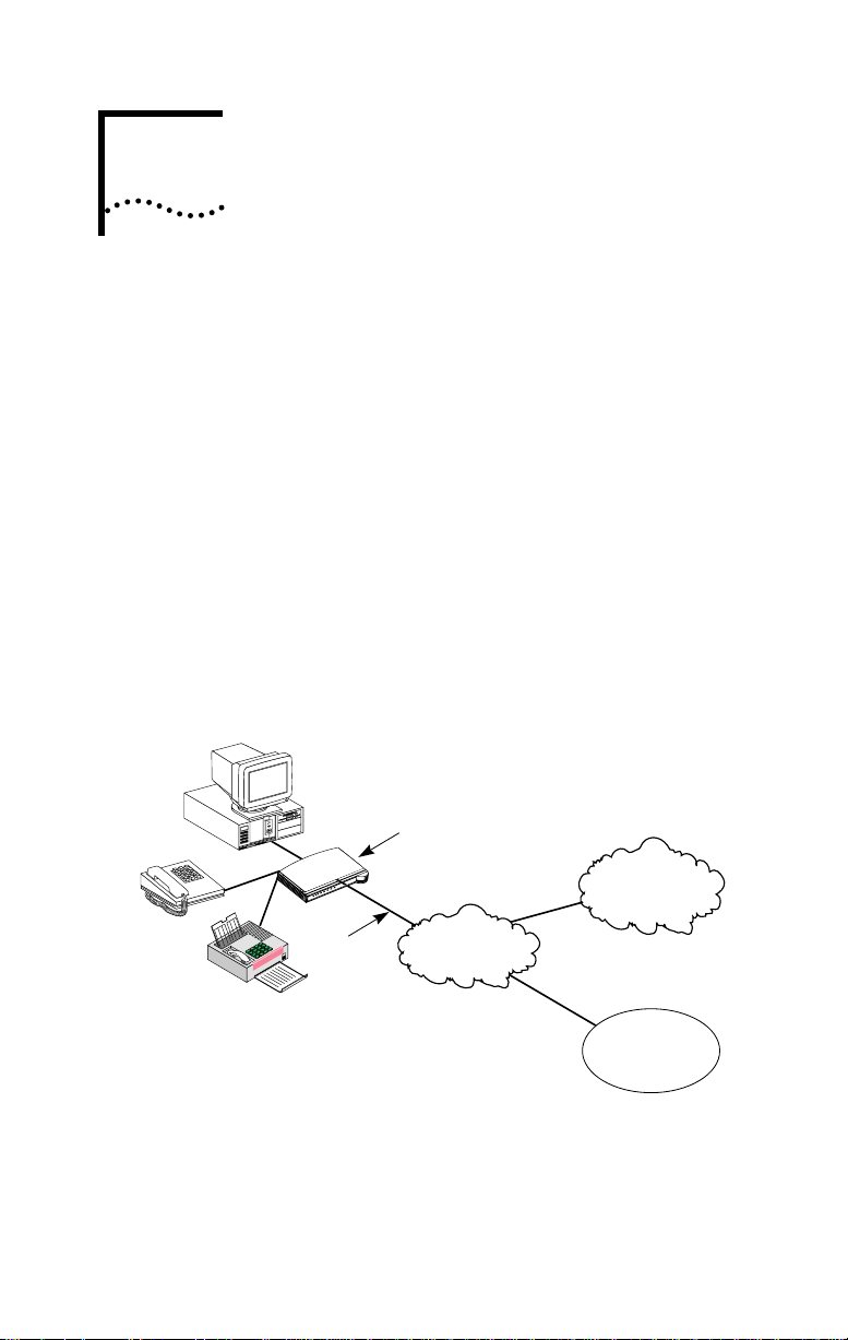
A typical 3C882 ISDN modem application is shown in
Figure 1-1.
or IBM-compatible
3ComImpact IQ
External ISDN Modem
Impact
3Com
TESTD B1 B2 SD RD DTR
R
PW
ISDN line
M
3 Com
T
Public telephone
network
Internet/intranet
or
on-line service
Corporate
LAN
Figure 1-1 Network Access with the 3C882 ISDN Modem
The 3C882 ISDN modem allows transmission of data at
speeds of up to 128 Kbps over digital ISDN connections with
Page 16

1-2 CHAPTER 1: INTRODUCTION
the highest reliability and error-free performance possible.
With hi/fn
compression and a high-speed serial port, the
3C882 ISDN modem allows you to reach transmission speeds
of up to 230.4 Kbps. ISDN technology reduces call setup
times by more than 50% compared to V. fast/V.34 analog
modem setup times; connection is established in 3 seconds.
Setting up the 3C882 ISDN modem takes only 15 minutes.
Simply connect the cables, load the software, run the SPID
Wizard™, and you are ready to place a call.
The 3C882 ISDN modem quickly processes data and voice
calls simultaneously. For example, you can send a fax or place
a voice telephone call while maintaining a high-speed
connection to the office LAN; you can also send or receive a
voice telephone call while you are connected to the Internet.
The 3C882 ISDN modem can be connected to any
compatible UL
RS-232-compliant serial ports.
-listed computer that includes
3C882 ISDN Modem Features
The 3C882 ISDN modem provides the following features.
Easy Installation and Use
■ SPID Wizard feature for automatic telephone company switch
and service profile ID (SPID) number configuration
■ Single screen, point-and-click user interface for configuration
■ Autobaud feature for automatic baud rate detection of your
computer’s COM port
■ QuickSelect
required protocol, either V.120 or PPP, for each data call
■ Automatic configuration verification with on-line registration
■ On-line Help
protocol detection that automatically senses the
Page 17

High Performance
■ hi/fn, version 5, compression, for data throughput of up to
230.4 Kbps, which conforms to these IETF RFC’s: The PPP
Compression Control Protocol (1962), and PPP LZS Compression
Protocol (1974)
■ An asynchronous RS-232-D data port for connectivity to IBM
or compatible PC and Apple Macintosh serial ports at rates of
up to 230.4 Kbps
■ Multilink PPP (RFC 1990), which creates a single digital
network connection of up to 128 Kbps
■ TollMizer, which places a data call over a voice connection,
saving you the additional charge for a data call
■ Support for Shiva’s Proprietary PPP Password Authentication
Protocol (SPAP), versions 2 and 3
Protocols
■ ANSI V.120 rate adaption
3C882 ISDN Modem Features 1-3
■ Async-Sync PPP™ feature, which automatically converts
asynchronous PPP into synchronous (HDLC-based) PPP ISDN
■ IETF PPP (RFC 1661)
■ IETF Multilink PPP
■ ISDN Call Logging
ISDN Standards and Interface
■ A complete digital network termination (Basic Rate
ISDN U interface with built in NT1)
■ Full ISDN signaling support of National ISDN
■ Compatible with AT&T, Northern Telecom, and Siemens
switches
Page 18

1-4 CHAPTER 1: INTRODUCTION
Security
■ Password Authentication Protocol (PAP) and Challenge
Handshake Authentication Protocol (CHAP) support on both
single-channel and Multilink PPP calls (IETF RFC 1994)
Voice Features
■ Dynamic bandwidth allocation (DBA), which allows you to
place or receive a voice call while a Multilink PPP call is active
■ Two analog voice ports for attaching analog telephone
equipment (touch-tone or cordless telephones, fax and
answering machines, and analog modems) to the ISDN line
■ Flexible call routing to the two analog ports
Upgradability
■ Flash memory for field firmware updates
■ Firmware posted on 3Com’s ftp and BBS sites
Diagnostics
■ LED status display
■ Test call compatibility
Warranty
■ 5-year limited warranty
3C882 ISDN Modem Package Contents
The 3C882 ISDN modem package contents contains one
each:
■ 3ComImpact IQ External ISDN Modem
■ Power cable with an AC wall transformer
■ RJ -45/RJ -11 ISDN telephone cable
■ 25-pin male to 9-pin female serial cable
Page 19

Before You Install the 3C882 ISDN Modem 1-5
■ 3.5-inch installation diskettes for PCs running Windows® 95,
Windows NT®, or Windows 3.x
■ 3.5-inch installation diskette for PCs running DOS
■ 3.5-inch installation diskette for Macintosh computers
■ 3ComImpact IQ External ISDN Modem User Guide
■ 3ComImpact IQ External ISDN Modem Quick Start
Instructions
■ RS232 Serial Port Cable
Before You Install the 3C882 ISDN Modem
To install and use the 3C882 ISDN modem successfully, you
must have the following:
■ Correct ISDN service installed at your location with an
available ISDN RJ-11 outlet. If you have not ordered ISDN
service yet, see Appendix A.
■ ISDN configuration information. Complete the ISDN
Information Sheet in the “ISDN Information” section of this
chapter.
■ A computer that meets UL standards in the United States or
is certified to CSA standards in Canada. Refer to the section
“IBM PC or Compatible Requirements” for an IBM or
IBM-compatible PC. Refer to the section “Apple Macintosh
Requirements” for an Apple Macintosh computer.
■ For Macintosh users, one 25-pin male to mini DIN 8-pin male
serial cable.
To order a free Macintosh serial cable, refer to the information
enclosed in your 3C882 ISDN modem package. If you are
supplying your own serial cable, ensure that it meets the pin
specifications provided in Appendix C.
Page 20

1-6 CHAPTER 1: INTRODUCTION
IBM PC or Compatible Requirements
An IBM-compatible PC must have the following:
■ A 386, 486, or Pentium
■ Microsoft
MS-DOS
■ 640 KB of conventional memory
■ A hard disk drive with 4 MB of free space
■ A high-density 3.5-inch floppy diskette drive
■ VGA or compatible video graphics adapter and monitor
Windows 95, Windows NT, or Windows 3.x,
, or IBM PC DOS 3.x or higher
processor
(color recommended)
■ An available serial communications port
For 230.4 Kbps data rate. You will need an enhanced serial
port card and COM port driver software that support
230.4 Kbps.
For 115.2 Kbps data rate. 3Com recommends that
your IBM or IBM-compatible PC serial COM port be
equipped with a 16C550 UART (universal asynchronous
receiver/transmitter). To determine what UART is installed in
your PC, run the Microsoft Diagnostic Program (msd) from
the DOS prompt.
Apple Macintosh Requirements
An Apple Macintosh computer must have the following:
■ An available serial communications port
■ System 7 or later operating system
■ A hard disk drive with 4 MB of free space
■ A high-density 3.5-inch floppy diskette drive
Page 21

ISDN Information
Enter your ISDN telephone number(s) in the information
sheet shown in Figure 1-2. You will need this information
during configuration of the 3C882 ISDN modem.
Although the 3C882 ISDN modem automatically configures
the ISDN switch type and Service Profile Identifier (SPID)
number(s), you should indicate the switch type and SPID(s), if
any were assigned. You may need to refer to this information
for technical support.
If necessary, ask your telephone company ISDN
representative for the ISDN information.
Before You Install the 3C882 ISDN Modem 1-7
ISDN Information Sheet
3ComImpact IQ ISDN Modem
ISDN Switch Type
AT&T 5ESS NI1 ❒
AT&T 5ESS Custom ❒
Northern Telecom DMS 100 ❒
Siemens EWSD
❒
Number of Telephone Numbers (1 or 2) ______
Phone #1______________________________
SPID # for Phone #1______________________
Phone #2______________________________
SPID # for Phone #2______________________
Figure 1-2 ISDN Information Sheet
ISDN Switch Type. Place a check mark next to the ISDN
switch your telephone company uses. Each switch type has a
corresponding provisioning table in Appendix A.
Number of ISDN Telephone Numbers. Your one ISDN
telephone line can support two ISDN telephone numbers. If
Page 22

1-8 CHAPTER 1: INTRODUCTION
you ordered one ISDN telephone number, write 1. If you
ordered two ISDN telephone numbers, write 2.
Ordering two ISDN telephone numbers allows you to conduct
two simultaneous calls on both analog phone ports.
ISDN Telephone Number 1. Write down your ISDN
telephone number provided to you by the telephone
company ISDN representative.
ISDN Telephone Number 2. Write the second ISDN phone
number if you ordered two ISDN telephone numbers for your
line.
SPID Number. If required by your telephone company, fill in
the SPID number for each ISDN phone number. Your
telephone company can tell you whether a SPID is required
and supply you with the correct value.
Page 23
2
INSTALLING THE 3C882
ISDN MODEM
This chapter describes installation of the 3C882 ISDN modem
for use with an IBM or IBM-compatible PC or an Apple
Macintosh computer.
This installation procedure assumes that you are familiar with
your Apple Macintosh or IBM-compatible computer. If you
are not, refer to the user guide that accompanied your
computer for instructions on hardware installation and
operating system commands.
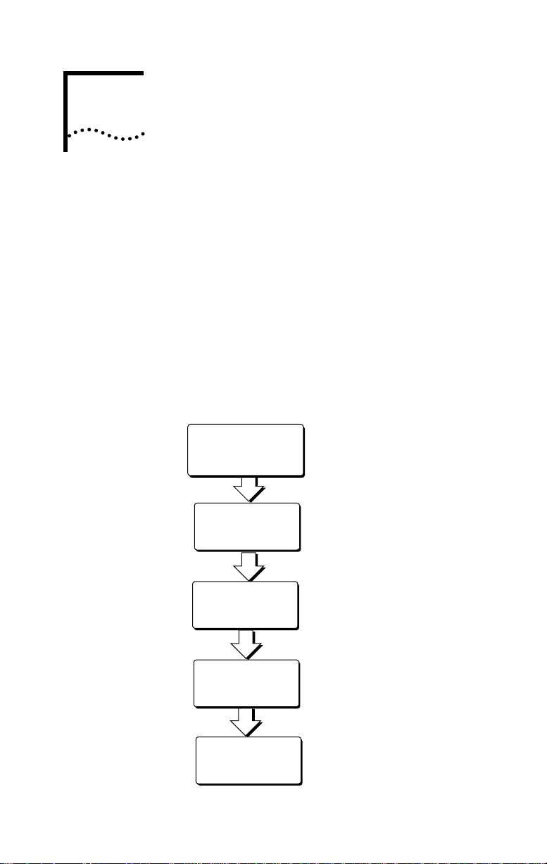
The main hardware installation steps are depicted in
Figure 2-1.
Familiarize yourself
with the
3C882 ISDN modem
Connect serial cable
Install ISDN cable
Install analog
equipment
(optional)
Install power cable
Figure 2-1 Installation Steps for the 3C882 ISDN Modem
Page 24
2-2 CHAPTER 2: INSTALLING THE 3C882 ISDN MODEM
Familiarizing Yourself with the 3C882 ISDN Modem
You should familiarize yourself with the components of the
front panel and back panel of the 3C882 ISDN modem prior
to installation.
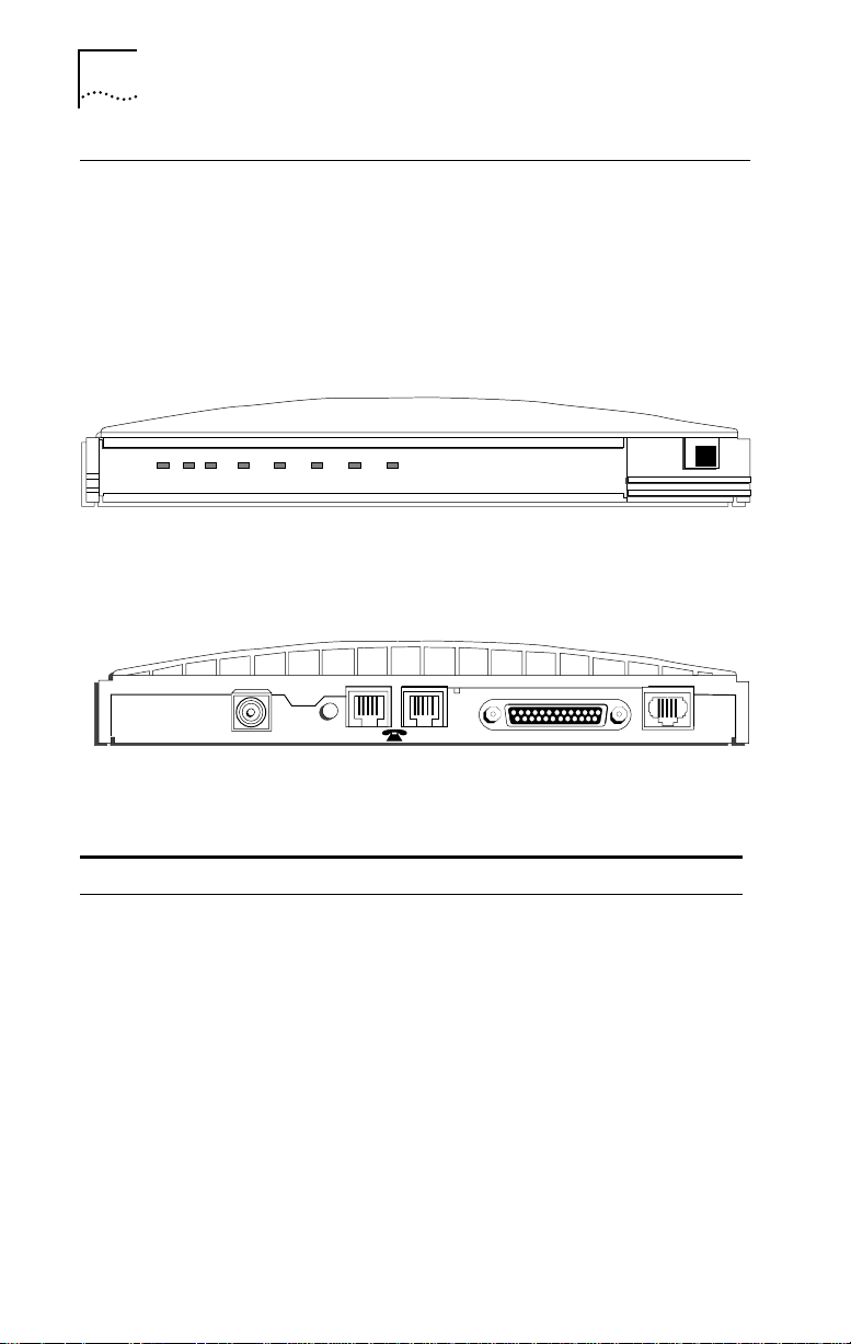
The LED status display, shown in Figure 2-2, consists of eight
front panel LEDs that are described in Table 2-1.
PWR TEST D B1 B2 SD RD DTR
3Com
Impact IQ
TM
3 Com
Figure 2-2 Front Panel LED Indicators
Figure 2-3 shows the back panel.
9 VDC
.6A MAX
Figure 2-3 Back Panel Connectors
Table 2-1 Front Panel LED Indicator Definitions
LED Color Description
PWR Green Power Indicator. Lit when power is on and remains lit as long
TEST Green Self-Test/Status. Flashes when the 3C882 ISDN modem is
RESET
12
RS-232 ISDN U
as power is supplied to the unit.
executing its power-up self-test or a user-initiated reset. If the
results of the self-test or reset are normal, the LED goes off. If
the result of the self-test is abnormal and a fault is detected,
the LED remains lit but does not flash.
Page 25

Installing a Serial Cable 2-3
LED Color Description
D Green D Channel Status. Indicates the ISDN physical network
B1 Amber
or
green
B2 Amber
or
green
interface and D channel status:
Goes off once the physical and D channel signaling are
synchronized.
Flashes if the physical interface establishes synchronization
and the ISDN D channel signaling procedures are not properly
established.
Remains lit if the physical ISDN interface is not synchronized or
is disconnected.
B1 Channel Activity. Green indicates a circuit-switched data
call in progress. Amber indicates a circuit-switched voice call in
progress. If a call is in a dialing state, the LED flashes. When the
call is disconnected, the LED goes off.
B2 Channel Activity. Green indicates a circuit-switched data
call in progress. Amber indicates a circuit-switched voice call in
progress. If a call is in a dialing state, the LED flashes. When the
call is disconnected, the LED goes off.
SD Green Send Data. Indicates that information is being transmitted
RD Green Receive Data. Indicates that information is being transmitted
DTR Green Data Terminal Ready. Indicates that communication between
over the serial data port from the computer to the ISDN
modem.
over the serial data port to the computer from the ISDN
modem.
the ISDN modem and computer has been established.
Installing a Serial Cable
You will need the following type of serial cable.
■ For a Macintosh computer, you will need a 25-pin male to
mini DIN 8-pin male serial cable. Refer to the information
enclosed in your 3C882 ISDN modem package to order a free
cable. If you are providing your own serial cable, ensure that
it meets the pin specifications provided in Appendix C.
■ For a PC, you will need the 25-pin male to 9-pin female serial
cable that was provided. For PCs with a 25-pin serial port
connector, you will need to purchase a standard 9-pin to
25-pin adapter.
Page 26
2-4 CHAPTER 2: INSTALLING THE 3C882 ISDN MODEM
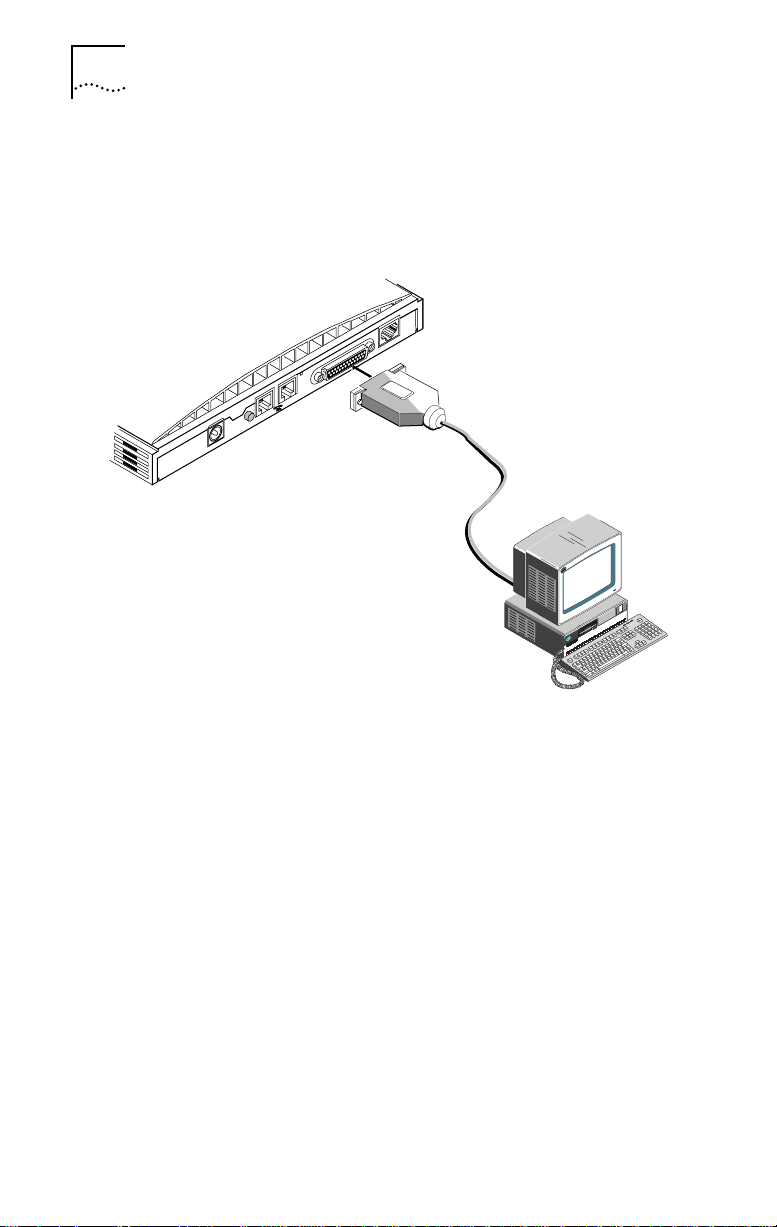
To install the 3C882 ISDN modem serial cable:
1 Insert the 25-pin male end of a serial signal cable into the
RS-232 serial port on the 3C882 ISDN modem’s back panel
and tighten the connector screws, as shown in Figure 2-4.
ISDN U
RS-232
12
RESET
9 VDC
.5A MAX
Figure 2-4 Computer to 3C882 ISDN Modem COM Port Connection
2 Connect the other end of the serial cable to a serial COM
port on the back of your computer and tighten the
connector screws.
On a PC, most COM port connectors are labeled COM,
SERIAL, or RS-232-D. On an IBM AT® PC and most laptops or
notebooks, connect the cable to a 9-pin COM port connector.
If your PC has a 25-pin serial port connector, you will need to
install a standard 9-pin to 25-pin adapter.
On a Macintosh computer, the COM port is the mini DIN
8-pin serial connector depicted by the telephone handset.
Page 27
1
Installing the ISDN Cable
To install the ISDN cable:
1 Connect the RJ-45 (8-pin) connector end of the
RJ-45/RJ-11 ISDN cable to the RJ-45 ISDN line port labeled
ISDN U on the 3C882 ISDN modem’s back panel, as shown
in Figure 2-5.
12
RESET
9 VDC
. 5A MAX
Figure 2-5 ISDN Cable Connection
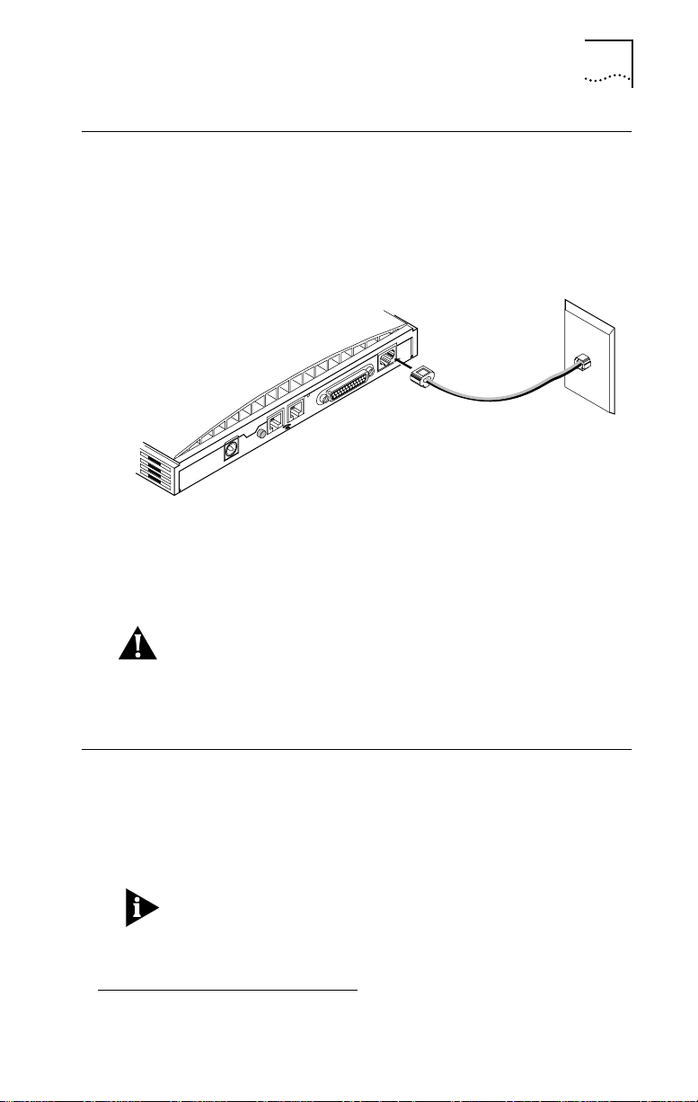
2 Connect the RJ-11 (6-pin) connector end of the
RJ-45/RJ-11 ISDN cable to the RJ-11 ISDN wall jack.
RS-232
Installing the ISDN Cable 2-5
ISDN U
CAUTION: An NT1 is built into the 3C882 ISDN modem.
Never connect the 3C882 ISDN modem ISDN port to a
standard analog telephone jack or to an external NT1 device.
Make sure that it is connected directly to the ISDN jack.
Installing Analog Equipment
You can connect an analog touch-tone telephone, answering
machine, fax machine, or external analog modem to the
3C882 ISDN modem.
You will need an RJ-11 to RJ-11 cable for each analog phone
port connection.
To install an analog device:
1.
Page 28
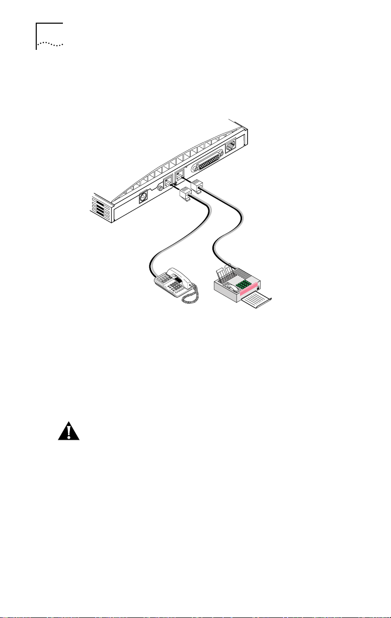
2-6 CHAPTER 2: INSTALLING THE 3C882 ISDN MODEM
1 Insert one RJ-11 connector to a phone port labeled with a
telephone icon on the back of the ISDN modem, as shown
in Figure 2-6.
ISDN U
RS-232
12
RESET
9 VDC
.5A MAX
Figure 2-6 Analog Equipment Connection
2 Insert the other RJ-11 end into the appropriate RJ-11 port
on the analog device.
3 If you have another analog device to install, repeat steps 1
and 2.
CAUTION: The 3C882 ISDN modem is designed to operate
with telephones that are compatible with the original AT&T
®
2500 touch-tone telephone standard. 3Com guarantees
proper operation of compatible touch-tone devices that do
not exceed a total ringer equivalency number (REN) of three
per analog port. The 3C882 ISDN modem is designed to
provide power and ringing for these three devices on up to
200 feet of AWG 26 or heavier AWG wiring. Although the
3C882 ISDN modem may function satisfactorily at longer
cable distances with more than two attached telephones,
proper operation at longer cable distances is not guaranteed
in all situations.
Page 29
Specialized telephone equipment such as speaker phones
that draw large amounts of power may not work on the
3C882 ISDN modem’s Phone port. Because these devices do
not conform to the power specification of the 2500
touch-tone telephone standard, their operation is not
guaranteed.
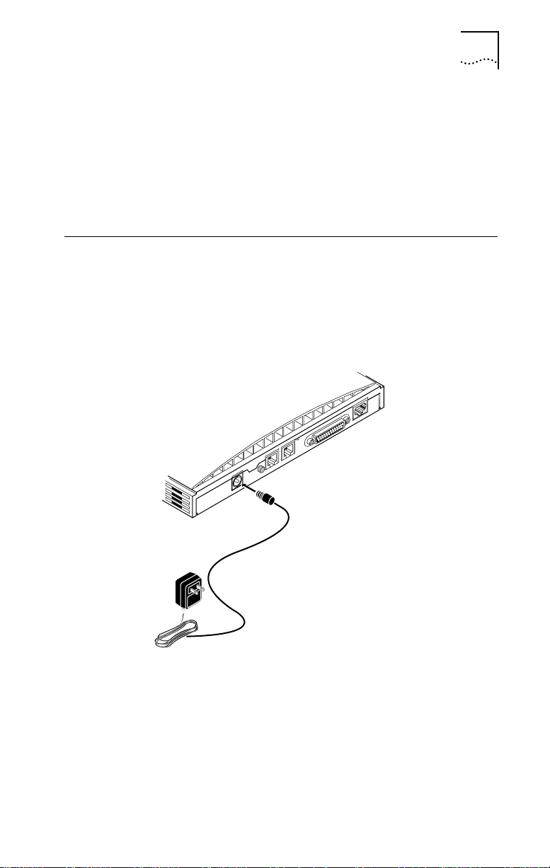
Installing the Power Cable
To install the power cable:
1 Connect the 3C882 ISDN modem power cable to the
9 VDC power connector on the back panel of the ISDN
modem, as shown in Figure 2-7.
Installing the Power Cable 2-7
ISDN U
RS-232
12
RESET
9 VDC
.5A MAX
Figure 2-7 Power Cable Connection
2 Plug the transformer end of the power cable into a surge-
protected standard 110 VAC wall outlet.
The indicator LEDs on the front panel (see Figure 2-2) flash
momentarily as the unit undergoes a power-up self-test
diagnostic.
Page 30

2-8 CHAPTER 2: INSTALLING THE 3C882 ISDN MODEM
This completes the 3C882 ISDN modem installation.
Refer to the appropriate chapter to configure the 3C882 ISDN
modem; either Chapter 3, “Configuration for an
IBM-Compatible PC Running Windows,”or Chapter 4,
“Configuration for an Apple Macintosh Computer.”
Page 31

3
CONFIGURATION FOR AN IBM-COMPATIBLE PC RUNNING WINDOWS
This chapter describes the 3C882 ISDN modem configuration
for use with the Windows operating system. Main topics are
as follows:
■ Configuring the 3C882 ISDN modem
■ Setup using Windows 95
■ Setup using Windows NT 3.5.1
■ Setup using Windows NT 4.0
■ Configuring Dial-Up Networking
■ Setup for 230Kbps
For instructions on using the DOS operating system, refer to
Appendix D.
Configuring the 3C882 ISDN Modem for a PC
The main steps are shown in Figure 3-1.
Install 3C882
software
Run
SPID Wizard
Configure
Multilink PPP,
B channel rate, &
voice call routing
Verify
configuration
Figure 3-1 Main Configuration Steps for a PC
Page 32

3-2 CHAPTER 3: CONFIGURATION FOR AN IBM-COMPATIBLE PC RUNNING WINDOWS
Installing the 3C882 Software
To install the 3C882 ISDN modem software:
1 Insert the 3ComImpact IQ Windows Installation Diagnostic
Utilities diskette into an available floppy drive.
2 If you are using Windows 95, select Run from the Start
menu. If you are using Windows 3.x, select Run from the File
menu. In the Run dialog box shown in Figure 3-2, type:
a:\setup
Figure 3-2 Run Dialog Box
3 Click OK.
After the configuration program is copied to the hard disk, a
welcome screen opens, as shown in figure Figure 3-3.
Figure 3-3 Welcome Screen for PC
Page 33

Configuring the 3C882 ISDN Modem for a PC 3-3
4 Click Next to continue the installation.
You will then be prompted to choose the directory in which
to install the software.
5 If you would like to designate a directory other than the
default directory, click Browse to do so. Otherwise, click
Next to install the 3ComImpact IQ into the default
directory.
If you are running Windows 3.x, a message box appears and
asks you whether you want to install a Microkey COM port
enhancement driver for data transfer rates up to 115.2 Kbps.
This driver will replace your existing COM port driver. If you
receive the following message during the Microkey
installation procedure:
ERROR DURING INSTALLATION, ERROR CODE
please record the error code (shown as XX above) and refer to
“” on page 8-7 for an explanation of the error code and the
corrective action to take.
After the setup program has completed installation, you are
asked to view the Readme file.
6 Click Ye s to review this file.
You may choose File and Print to create a hardcopy of the
Readme. Otherwise, read the file and exit. A message box
confirms that the installation is complete.
7 Click OK to complete the installation.
Running the SPID Wizard
The SPID Wizard automatically detects your telephone
company’s switch type and configures the SPID(s).
You will need the ISDN telephone numbers from the ISDN
Information Sheet you completed in Chapter 1.
XX
Page 34

3-4 CHAPTER 3: CONFIGURATION FOR AN IBM-COMPATIBLE PC RUNNING WINDOWS
1 Double-click the 3ComImpact IQ icon shown in Figure 3-4.
Figure 3-4 3ComImpact IQ Globe Icon
You will see a start message, as shown in Figure 3-5.
Figure 3-5 SPID Wizard Start Message for PC
If you do not want to run the SPID Wizard, click Cancel to
configure your values manually via the configuration dialog
box (see Figure 3-9). Here you can select your ISDN switch
type, enter the telephone number(s) and, if required, enter the
corresponding SPID(s) for your ISDN line. Note that running
the SPID Wizard is the recommended method for configuring
your SPID values.
The SPID Wizard first checks for ISDN layer 1status, and then
configures the switch type.
Page 35

Configuring the 3C882 ISDN Modem for a PC 3-5
After the switch type is configured, the dialog box for the
first telephone number appears, as shown in Figure 3-6.
Figure 3-6 First Telephone Number Dialog Box for PC
2 Enter the first telephone number for your ISDN line.
3 Click Next.
A message appears, indicating that the 3C882 ISDN modem
is detecting the SPID for the first telephone number.
Page 36

3-6 CHAPTER 3: CONFIGURATION FOR AN IBM-COMPATIBLE PC RUNNING WINDOWS
After the SPID is configured, the dialog box shown in
Figure 3-7 appears.
Figure 3-7 Second Telephone Number Dialog Box for PC
4 If you have a second telephone number for your ISDN line,
enter it, and then click Next. If not, leave the field
incomplete, and then click Done.
After successful configuration of your switch type and SPID
number(s), Figure 3-8 appears.
Figure 3-8 Successful Configuration Dialog Box
Page 37

Configuring the 3C882 ISDN Modem for a PC 3-7
5 Click Finish.
The on-line registration dialog box appears. Enter your
information and then click Register Now.
After your information is received, the Successful Registration
dialog box will open.
6 Click OK.
A message box indicates that you have correctly configured
your 3C882 ISDN modem.
7 Click No to verify your settings and continue the setup
procedure (recommended). To exit the installation
program and leave the default settings, click Yes .
If you clicked No, the Configuration dialog box will open, as
shown in Figure 3-9.
Figure 3-9 Configuration Dialog Box for PC
Page 38

3-8 CHAPTER 3: CONFIGURATION FOR AN IBM-COMPATIBLE PC RUNNING WINDOWS
A message bar at the bottom of the dialog box provides status
information about the 3C882 ISDN modem.
The Configuration dialog box buttons do the following.
Help. Click the Help button to access help for the
Configuration dialog box. There is also comprehensive
on-line help accessible from the 3ComImpact IQ program
group box.
Tools. Clicking on the Tools button produces buttons for
Firmware, Tests, Save and Restore.
■ Firmware. Refer to the readme file for firmware download
instructions.
■ Tests. Use the Tests tool only under the direction of
technical support personnel.
■ Save. Pressing the Save button saves the current
Configuration dialog box settings in a file you name. You
can easily restore a previously saved file to the
Configuration dialog box.
■ Restore. Pressing the Restore button restores the 3C882
ISDN modem to a previously saved configuration file.
Update. Click the Update button to download any
configuration parameter changes made to the Configuration
dialog box. After you click the Update button, the name
changes to Updated to indicate that the changes have been
saved to your ISDN modem’s S registers.
Exit. Click Exit to leave the Configuration dialog box.
Running the SPID Wizard Again
The SPID Wizard automatically runs when you are
configuring the 3C882 ISDN modem for the first time, if you
connect the 3C882 ISDN modem to a different ISDN line, or if
your ISDN line parameters should change (e.g., your area
code). After the ISDN switch type, telephone number(s), and
Page 39

Configuring the 3C882 ISDN Modem for a PC 3-9
SPID(s) are configured, clicking on the 3ComImpact IQ globe
icon will thereafter display the Configuration dialog box.
If you add a second telephone number to your ISDN line
after you run the SPID Wizard, you can use the SPID Wizard to
detect the SPID for your second telephone number.
To run the SPID Wizard for a second telephone number:
1 From the Configuration dialog box, check the Enabled box
located in the Number 2 group box.
A message box appears and asks you to confirm that you
want to run SPID Wizard.
2 Click OK.
The Second Telephone Number dialog box appears.
3 Enter the second telephone number for your ISDN line
and then click Next.
Figure 3-8 appears.
4 Click Finish.
Configuring Multilink PPP
Multilink PPP is a protocol that provides a method for
combining multiple PPP connections. Multilink PPP combines
the two ISDN B channels, creating a virtual single digital
connection of up to 128 Kbps. Note that the destination you
are dialing must also support Multilink PPP, or you will get a
single B channel connection instead of the dual-channel link.
By default, Multilink PPP is enabled. To enable or disable
Multilink PPP, do the following:
1 Click inside the Multilink check box in the PPP area to
clear it (disable) or check it (enable).
2 Click the Update button to download the change to your
3C882 ISDN modem’s S register.
Page 40

3-10 CHAPTER 3: CONFIGURATION FOR AN IBM-COMPATIBLE PC RUNNING WINDOWS
Additional configuration may be needed for Multilink PPP. For
details refer to S registers 82 and 83 in Appendix B, “AT
Commands, S Registers, and Result Codes”.
Note that if you disable Multilink PPP (i.e., Register S80=0),
you can still place a Multilink PPP call without changing the
S 80 register value. In the dial string, enter the first telephone
number, then the ampersand character followed by the
second telephone number. For example:
ATD 908 555 1212 & 908 555 1213
Configuring the B Channel Rate
Specify the B channel rate as 56 Kbps, 64 Kbps, or select
TollMizer if you would like to use that feature. TollMizer
allows you to place a 56 Kbps data call using a voice channel,
which is often less expensive. Note that the device you are
calling must also support TollMizer (sometimes referred to as
Switch 56 Permissive or Data Over Voice) to take advantage
of this feature.
By default, the B channel rate is 56 Kbps. Check with your
telephone company for the appropriate B channel rate.
To change the connection speed to 64 Kbps or TollMizer, do
the following:
1 Select the appropriate radio button (64 Kbps or TollMizer).
2 Click the Update button to download the change to your
3C882 ISDN modem’s S register.
Configuring Voice Call Routing
The 3C882 ISDN modem allows you to assign a specific
telephone number to a specified analog phone port. By
default, telephone number 1 is assigned to phone port one,
and telephone number 2 is assigned to phone port two, as
shown in Figure 3-10. This is especially helpful should you
Page 41

Configuring the 3C882 ISDN Modem for a PC 3-11
have both a telephone and a fax machine connected to your
3C882 ISDN modem’s analog ports.
ISDN U
RS-232
12
RESET
9 VDC
• 5A MAX
908 555 1212 908 555 1213
Figure 3-10 Voice Call Routing Default Setting
Note the phone port check marks for each telephone
number. This default configuration routes each telephone
number to a specified port.
The ISDN Call Waiting default configuration is best served by
the recommended scenario shown in Figure 3-10. By default,
ISDN Call Waiting has been enabled on Phone Port 1, for use
with your telephone, but disabled on Phone Port 2 to prevent
potential interruption of calls to your fax machine (S76=1).
One Telephone Number and Two Analog Devices.
If you have only one telephone number for your ISDN line
and two analog devices, check the Phone Port 1 and Phone
Port 2 boxes located in the Number 1 group box, as shown in
Figure 3-11. Calls to that telephone number will ring both
devices, allowing you to answer a call using either device.
Page 42

3-12 CHAPTER 3: CONFIGURATION FOR AN IBM-COMPATIBLE PC RUNNING WINDOWS
Note that while you are using the fax machine, for example,
you cannot use the telephone to place or receive calls
because your ISDN line has only one telephone number.
ISDN U
RS-232
12
RESET
9 VDC
• 5A MAX
908 555 1212 908 555 1212
Figure 3-11 Configuration for One Telephone Number and Two
Devices
Two Telephone Numbers and Two Analog Devices.
If you have two telephone numbers and two analog devices
attached to your 3C882 modem, you can choose to have
both ISDN telephone numbers ring both devices
simultaneously. For this scenario, you would place a
checkmark in all four Phone Port boxes, as shown in
Figure 3-12
ISDN U
RS-232
12
RESET
9 VDC
• 5A MAX
908 555 1212 908 555 1212
908 555 1213
908 555 1213
Figure 3-12 Configuration for Two Telephone Numbers and Two
Analog Devices
Page 43

Configuring the 3C882 ISDN Modem for a PC 3-13
To change the voice call routing setting:
1 Specify which Phone port should handle the calls
associated with Telephone Number 1 by checking the
appropriate Phone Port box.
2 If your ISDN line has two telephone numbers, specify
which Phone port should handle the calls associated with
Telephone Number 2.
3 Click the Update button to download the change to your
3C882 ISDN modem’s S register.
Verifying the Configuration
Check the status bar located toward the bottom of the
Configuration dialog box. If the parameters were configured
accurately and the 3C882 ISDN modem is ready to send and
receive calls, the status bar fields will appear as shown here.
■ Layer 1: UP
■ SPID 1: Init (if required)
■ TEI 1: Number from 64 to 126
■ SPID 2: Init (if required)
■ TEI 2: Number from 64 to 126 (if required)
The TEI number(s) are not configured by the user. The TEI
number(s) are transmitted by the telephone company for
informational purposes only.
Before you close the Configuration dialog box, do the
following.
1 Confirm that the Configuration parameters are correct.
Page 44

3-14 CHAPTER 3: CONFIGURATION FOR AN IBM-COMPATIBLE PC RUNNING WINDOWS
2 Click the Update button if you made any changes to the
3C882 ISDN modem configuration.
3 Click Exit to leave the utility.
This completes the ISDN modem configuration procedure.
For Windows 3.x users, go to Chapter 5, “Advanced
Configuration,” and review the default settings to ensure that
they reflect your preferences. If you prefer not to change the
default settings, go on to Chapter 7, “Placing and Receiving
Calls”.
If you are using Windows 95, Windows NT 3.5.1, or Windows
NT 4.0, refer to the appropriate section, “Setup Using
Windows 95”, “Setup Using Windows NT 3.5.1 RAS”, or “Setup
for Windows NT 4.0” for additional instructions.
For information regarding configuration of the 3C882 ISDN
modem with various Internet access software not included in
this User Guide, use the 3Com fax service (1) (408) 727-7021
(analog) in the U.S. or visit 3Com’s World Wide Web site at
http://www.3Com.com/.
Page 45

Setup Using Windows 95
This section describes how to set up the 3C882 ISDN modem
using Windows 95 Plug and Play. These instructions assume
that Windows 95, Microsoft Plus!, and the 3C882 ISDN
modem software have already been installed.
To setup your 3C882 ISDN manually and bypass Windows 95
Plug and Play, refer to the section “Setup for Windows NT 4.0”
below.
1 Reboot your PC with the 3C882 ISDN modem powered up
and physically connected to your PC.
The New Hardware dialog box appears, shown in Figure 3-13.
Setup Using Windows 95 3-15
Figure 3-13 New Hardware Dialog Box
2 Select the Driver from disk provided by hardware
manufacturer option.
3 Click OK.
Page 46

3-16 CHAPTER 3: CONFIGURATION FOR AN IBM-COMPATIBLE PC RUNNING WINDOWS
The Install From Disk dialog box appears, as shown in
Figure 3-14.
Figure 3-14 Install From Disk Dialog Box
4 Insert the 3ComImpact IQ Windows Installation Diagnostic
Utilities diskette into an available floppy drive.
5 Click OK.
The Select Device dialog box appears, as shown in
Figure 3-15.
Figure 3-15 Select Device Dialog Box
Page 47

Setup Using Windows NT 3.5.1 RAS 3-17
6 Check Show All Devices.
7 Select 3ComImpact IQ for baud rates of up to 115.2Kbps
and click Next.
The 3C882 ISDN modem allows for transfer rates of up to
230.4 Kbps. However, some computers require the installation
of additional hardware, such as an accelerated serial port
card, to take advantage of this higher speed. Additional
configuration steps, as well, are required. Refer to “Setup for
230Kbps” for instructions.
8 Click OK.
This completes the setup procedure for Windows 95. Refer to
“Configure Dial-Up Networking” to setup a remote access
configuration, or continue on to Chapter 5, “Advanced
Configuration,” to review the default settings and ensure that
they reflect your preferences. If you prefer not to change the
default settings, then go on to Chapter 7, “Placing and
Receiving Calls”.
Setup Using Windows NT 3.5.1 RAS
This section describes how to set up the 3C882 ISDN modem
using Windows NT RAS version 3.5.1. Note that these
instructions assume that the 3C882 ISDN modem software
has already been installed.
1 Using the File Manager, locate the Windows NT
MODEM.INF file in the %SystemRoot%/System32/RAS
directory and rename it MODEM.ORG.
For example, if your root directory is Windows, you would
look for the Windows NT MODEM.INF file in the following
directory:
C:\windows\System32\RAS
Page 48

3-18 CHAPTER 3: CONFIGURATION FOR AN IBM-COMPATIBLE PC RUNNING WINDOWS
2 Copy the 3C882 ISDN modem MODEM.INF file to the same
directory as the MODEM.ORG file.
3 From the main menu, select Control Panel, and then select
Network.
The Network Settings dialog box appears, as shown in
Figure 3-16.
Figure 3-16 Network Settings Dialog Box
4 From the Installed Network Software list box, select
Remote Access Service and then click Configure.
Page 49

Setup Using Windows NT 3.5.1 RAS 3-19
The Remote Access Setup dialog box appears, as shown in
Figure 3-17.
Figure 3-17 Remote Access Setup Dialog Box
5 If a modem is already configured, select it, and then click
Remove.
6 Click Add.
The Add Port dialog box appears.
7 Select a COM port, and then click OK.
The Remote Access Setup message box appears.
8 Click Cancel.
The Configure Port dialog box appears.
9 Select 3ComImpact IQ for baud rates up to 115.2 Kbps and
then specify the port usage. Click OK.
The 3C882 ISDN modem allows for transfer rates of up to
230.4 Kbps. However, some computers require the installation
of additional hardware, such as an accelerated serial port
card, to take advantage of this higher speed. Additional
configuration steps, as well, are required. Refer to “Setup for
230Kbps” for instructions.
The Remote Access Setup dialog box appears.
Page 50

3-20 CHAPTER 3: CONFIGURATION FOR AN IBM-COMPATIBLE PC RUNNING WINDOWS
10 Click Continue.
11 Click OK to exit the Network Settings dialog box.
The Network Settings Change alert box appears.
12 Click Restart Now.
Once your computer has rebooted, you are ready to use the
3C882 ISDN modem.
Refer to Chapter 5, “Advanced Configuration,” to review the
default settings and ensure that they reflect your preferences.
If you prefer not to change the default settings, then go on
to Chapter 7, “Placing and Receiving Calls”.
Setup for Windows NT 4.0
This section describes how to set up the 3C882 ISDN modem
using Windows NT 4.0. Note that these instructions assume
that the 3C882 ISDN modem software has already been
installed.
These instructions also apply for Windows 95 manual setup.
1 Insert the 3ComImpact IQ Windows Installation Diagnostic
Utilities diskette into an available floppy drive.
2 From the Control Panel dialog box, double-click the
Modems icon.
The Modems Properties dialog box appears.
3 Click Add.
The Install New Modem dialog box appears, as shown in
Figure 3-18.
Page 51

Setup for Windows NT 4.0 3-21
Figure 3-18 Install New Modems Dialog Box
4 Check Don’t detect my modem, I will select it from a list and
click Next.
Page 52

3-22 CHAPTER 3: CONFIGURATION FOR AN IBM-COMPATIBLE PC RUNNING WINDOWS
The New Modem Manufacture screen will open, as shown in
Figure 3-19.
Figure 3-19 Modem Manufacturers and Models Dialog Box
You will only see a 3Com entry if you have previously installed
a 3Com modem.
5 Click Have Disk.
6 Select 3ComImpact IQ for baud rates of up to 115.2K and
click Next.
The 3C882 ISDN modem allows for transfer rates of up to
230.4 Kbps. However, some computers require the installation
of additional hardware, such as an accelerated serial port
card, to take advantage of this higher speed. Additional
configuration steps, as well, are required. Refer to “Setup for
230Kbps” for instructions.
7 Select the appropriate COM port to which your modem is
connected.
8 Click Next.
Page 53

Configure Dial-Up Networking 3-23
A dialog box indicates successful setup.
9 Click Finish.
This completes the setup procedure for Windows NT 4.0.
Refer to “Configure Dial-Up Networking” below to setup a
remote access configuration, or continue on to Chapter 5,
“Advanced Configuration,” to review the default settings and
ensure that they reflect your preferences. If you prefer not to
change the default settings, then go on to Chapter 7, “Placing
and Receiving Calls”.
Configure Dial-Up Networking
This section describes the Dial-Up Networking setup
procedure for both Windows 95 and Windows NT 4.0
Dial-Up Networking setup requires specific Internet Service
Provider (ISP) information; your particular setup parameters
may vary widely. You may need to check with your ISP for
assistance.
Dial Up Networking for Windows 95
If you would like to connect to the Internet, you can choose
to have the Internet Setup Wizard to guide you through the
procedure or you may choose to configure Dial-Up
Networking manually for other remote connections.
To configure Dial-Up Networking manually:
1 From the Start menu, select Programs, Accessories, and
Dial-Up Networking.
The Dial-Up Networking window opens.
2 Double click the Make New Connection icon.
3 Enter a name for this connection (such as your ISP).
4 Select 3ComImpact IQ for baud rates up to 115.2 Kbps.
Page 54

3-24 CHAPTER 3: CONFIGURATION FOR AN IBM-COMPATIBLE PC RUNNING WINDOWS
If you have not already set up the modem for 230K, refer to
“Setup for 230Kbps” for assistance.
5 Click Configure.
The 3ComImpact IQ Properties window opens.
6 Select the appropriate COM port and maximum speed
available for your computer.
7 Click OK.
You are returned to the Make New Connection screen.
8 Click Next.
Enter the area code, telephone number and (if necessary) the
country code of the location you are dialing.
9 Click Next.
10 Click Finish.
To make a call, double click the connection icon for the
destination you wish to access. A connection dialog box will
open.
11 Click Connect.
Once your call has been established, you may open any web
browser to access the Internet.
Running the Internet Set-Up Wizard
The Internet Set-Up Wizard automates the configuration
procedure for connecting to the Internet. You will need the
following information, which your Internet Service Provider
(ISP) should supply:
■ Name of you ISP
■ Your ISP access number
■ Your user name and password
■ IP Address (if required)
Page 55

Configure Dial-Up Networking 3-25
■ Subnet Mask (if required)
■ Primary and Alternate DNS Server address
To send and receive e-mail through the Internet:
■ E-mail address
■ Mail server address
To run the Internet Set-Up Wizard, do the following:
The Internet Set-Up Wizard procedure may vary depending on
your particular version of Windows 95.
1 Click Start, Programs, Accessories, Internet Tools, and
Internet Setup Wizard.
2 Click Next to view the Connection Type dialog box.
3 Select Connect Using My Phone Line. Click Next to view the
Connection Type dialog box.
4 Choose to “Connect to the Internet using an Internet
Service Provider”.
5 Click Next.
If this is the first time you are running the Internet Setup
Wizard, the Installing Files dialog box appears.
6 Click Next.
The Choose Modem dialog box opens.
7 Select 3ComImpact IQ for baud rates of up to 115.2 Kbps
or 3ComImpact IQ 230K if you have installed an
accelerated serial port for higher baud rates. You must
have already followed specific setup instructions for
operating at 230K.
If you have not already set up the modem for 230K, refer to
“Setup for 230Kbps” for assistance.
8 Click Next.
Page 56

3-26 CHAPTER 3: CONFIGURATION FOR AN IBM-COMPATIBLE PC RUNNING WINDOWS
The Service Provider dialog box opens.
9 Enter the name of your ISP and click Next.
The Phone number dialog box opens.
10 Enter the area code, telephone number and (if necessary) the
country code of the location you are dialing.
11 Click Next.
The User Name and Password dialog box will open.
12 Enter your user name and password and click Next.
13 Configure as specified by your ISP and click Next.
14 Enter the IP address of your DNS server and click Next.
15 Choose the appropriate box to send and receive email
through the Internet. Then enter your email address (e.g.,
username@isp.com) and your Internet mail server address.
16 Click Next and Finish to exit the Internet Setup Wizard.
This completes the setup procedure for the Internet Setup
Wizard. Refer to Chapter 5, “Advanced Configuration,” to
review the default settings and ensure that they reflect your
preferences. If you prefer not to change the default settings,
then go on to Chapter 7, “Placing and Receiving Calls”.
Dial-up Networking for Windows NT 4.0
To configure Dial-Up Networking for Windows NT 4.0, follow
these instructions.
1 Click Start, Programs, Accessories, and Dial-Up-Networking.
Click New to create a new connection.
Page 57

Configure Dial-Up Networking 3-27
The New Phonebook Entry screen opens, as shown in
Figure 3-20.
Figure 3-20 New Phonebook Entry Wizard
If you have not yet configured a Dial-Up Networking
connection, a message will indicate that your phonebook is
empty. Click OK to add an entry.
2 Type a name for your connection, and click Next.
3 Select “I’m calling the Internet” and click Next.
4 Enter your ISP’s ISDN access number, and click Next.
5 Click Finish to close the New Phonebook Entry Wizard.
The Phonebook entry screen opens, as shown in Figure 3-21.
Page 58

3-28 CHAPTER 3: CONFIGURATION FOR AN IBM-COMPATIBLE PC RUNNING WINDOWS
Figure 3-21 Phonebook Entry Screen
You now have an opportunity to verify various settings of
your Dial-Up Networking connection.
6 Click More, and select “Edit entry and modem properties”.
Verify your ISP’s ISDN access number and your modem
selection.
7 Click the Server tab. The Server Type screen opens, as
shown in Figure 3-22.
Figure 3-22 Server Type Screen
Page 59

Configure Dial-Up Networking 3-29
8 Choose “PPP: Windows NT, Windows 95 Plus, Internet”
from the Dial-up server type drop down box.
9 Check TCP/IP if you are dialing into an ISP for Internet
access.
If you are accessing a remote network, such as a corporate
LAN, check with your MIS network administrator for the
appropriate Network Protocols.
10 Click the TCP/IP Settings button.
In most cases your ISP will provide a dynamic IP address; if so
check “Server assigned IP address”. Enter your DNS and WINS
server addresses if required.
If your ISP has assigned you a dedicated IP address, click
“Specify an IP Address” and enter it here.
11 Click OK to return to the Phonebook Entry screen.
12 Click the Script tab. Set Script to None unless otherwise
specified by your ISP.
13 Click the Security tab.
Change the Authentication method to “Accept any
authentication, including clear text” for PAP authentication or
“Accept Only Encrypted Authentication” for CHAP.
14 Click OK.
The 3C882 ISDN modem does not support Microsoft
Encrypted Authentication. X.25 is not supported either;
therefore, no changes are required on the X.25 screen.
This completes the Dial-Up Networking setup procedure for
Windows NT 4.0. Refer to Chapter 5, “Advanced
Configuration,” to review the default settings and ensure that
they reflect your preferences. If you prefer not to change the
default settings, then go on to Chapter 7, “Placing and
Receiving Calls”.
Page 60

3-30 CHAPTER 3: CONFIGURATION FOR AN IBM-COMPATIBLE PC RUNNING WINDOWS
Setup for 230Kbps
The 3C882 ISDN modem allows for transfer rates of up to
230.4 Kbps. Note that some computers require the
installation of additional hardware, such as an accelerated
serial port card, to take advantage of this higher speed.
There are two setup scenarios covered:
■ 230K setup for Windows NT 3.5.1
■ 230K setup for Windows 95 and Windows NT 4.0
Setting up 230K for Windows NT 3.5.1
These instructions require prior installation of the modem.inf
driver, which is installed as part of the initial setup procedure.
Refer to “Setup Using Windows NT 3.5.1 RAS” earlier in this
chapter for assistance.
1 Ensure that your computer’s COM port and
communications software support 230.4 Kbps.
For instructions on sending AT commands, refer to the section
“Changing the Parameter Settings” on page 5-4.
2 Using terminal emulation software send the command
$B 230400
to the 3C882 ISDN modem. This will set the
baud rate to 230.4 Kbps.
Once the baud rate is set to a fixed amount you will no longer
be able to access the Configuration dialog box to make
changes. Refer to “Restoring the 3C882 ISDN Modem to
Autobaud” on page 8-9 for assistance.
3 Save this setting by entering
AT&W and press return.
Next you must install the 230K driver to take advantage of
the speed increase.
AT
Page 61

Setup for 230Kbps 3-31
4 From the Main menu, select Control Panel, then select
Network.
The Network Settings dialog box appears.
5 Click Configure.
The Remote Access Setup dialog box appears.
6 Click Configure.
7 Select 3ComImpact IQ 230K.
8 Click OK.
9 Change the setting of your application program to 230400
bps.
This completes the procedure to change the baud rate to
230.4 Kbps for Windows NT 3.5.1.
Refer to Chapter 5, “Advanced Configuration,” to review the
default settings and ensure that they reflect your preferences.
If you prefer not to change the default settings, then go on
to Chapter 7, “Placing and Receiving Calls”.
Setting up 230K for Windows 95 and Windows NT 4.0
These instructions require prior installation of the impact.inf
driver, which is installed as part of the initial setup procedure.
Refer to “Setup Using Windows 95” or “Setup for Windows NT
4.0” earlier in this chapter for assistance.
1 Ensure that your computer’s COM port and
communications software support 230.4 Kbps.
For instructions on sending AT commands, refer to the section
“Changing the Parameter Settings” on page 5-4.
2 Using terminal emulation software (such as
HyperTerminal) send the command
AT $B 230400 to the
Page 62

3-32 CHAPTER 3: CONFIGURATION FOR AN IBM-COMPATIBLE PC RUNNING WINDOWS
3C882 ISDN modem. This will set the baud rate to 230.4
Kbps.
Once the baud rate is set to a fixed amount you will no longer
be able to access the Configuration dialog box to make
changes. Refer to “Restoring the 3C882 ISDN Modem to
Autobaud” on page 8-9 for assistance.
3 Save this setting by entering
AT&W and press return.
Next you must install the 230K driver to take advantage of
the higher baud rate.
4 From the Control Panel dialog box, double click the
Modems icon.
The Modems Properties dialog box appears.
5 Click Add.
The Install New Modem dialog box appears.
6 Check the box to prevent automatic detection of the
3ComImpact IQ ISDN modem and click Next.
The dialog box listing modem manufacturers and modem
models appears.
7 From the Manufacturers list box, select 3COM, and from
the Models list box, select 3ComImpact IQ 230K.
8 Click Next.
9 Select the appropriate COM port. and click Next.
A dialog box indicates successful setup.
10 Click Finish.
11 Be sure to change the setting of your application program
(such as Dial-Up Networking for Windows 95) to 230400
bps.
Page 63

Setup for 230Kbps 3-33
This completes the procedure to change the baud rate to
230.4 Kbps for Windows 95 and Windows NT 4.0.
Refer to Chapter 5, “Advanced Configuration,” to review the
default settings and ensure that they reflect your preferences.
If you prefer not to change the default settings, then go on
to Chapter 7, “Placing and Receiving Calls”.
Page 64

3-34 CHAPTER 3: CONFIGURATION FOR AN IBM-COMPATIBLE PC RUNNING WINDOWS
Page 65

CONFIGURATION FOR AN
4
APPLE MACINTOSH
COMPUTER
This chapter describes the configuration for the 3C882 ISDN
modem for use with an Apple Macintosh computer. Main
topics covered are:
■ Configuring the 3C882 ISDN modem
■ Configuring Internet access for a Macintosh computer
You will need the ISDN telephone numbers from the ISDN
Information Sheet you completed in Chapter 1.
Configuring the 3C882 ISDN Modem for a
Macintosh Computer
The main steps are shown in Figure 4-1.
Install 3C882
software
Run
SPID Wizard
Configure
Multilink PPP,
B channel rate, &
voice call routing
Verify
configuration
Figure 4-1 3C882 Configuration Steps for a Macintosh
Page 66

4-2 CHAPTER 4: CONFIGURATION FOR AN APPLE MACINTOSH COMPUTER
Installing the 3C882 Software
To install the 3C882 ISDN modem software in an Apple
Macintosh computer:
1 Insert the 3ComImpact IQ Installer Diagnostic Utilities
software utility diskette into the floppy drive and then
double-click the 3ComImpact IQ Installer icon.
A message box appears as shown in Figure 4-2.
Figure 4-2 Installation Message Box
2 Click Continue.
The Readme file opens. You can choose to review the
document or print the file.
3 Click Continue to install the software.
The Software Installation Location dialog box opens.
4 Select the location on your hard drive where you would
like to install the 3ComImpact IQ folder. If you do not want
to use the default folder name, it may be changed.
5 Click Install.
After the 3ComImpact IQ ISDN modem software is installed,
Figure 4-3 will open.
Page 67

Configuring the 3C882 ISDN Modem for a Macintosh Computer 4-3
Figure 4-3 Successful Installation Message Box
6 Click OK.
This completes the software installation.
Running the SPID Wizard
The SPID Wizard automatically detects your telephone
company’s switch type and configures the SPID(s). The SPID
Wizard automatically runs when you are configuring the
3C882 ISDN modem for the first time, if you connect the
3C882 ISDN modem to a different ISDN line, or if any of your
ISDN line parameters have changed (e.g., an area code). Once
the ISDN switch type, telephone number(s) and SPID(s) have
been configured, clicking on the 3ComImpact IQ program
icon will thereafter directly display the Configuration dialog
box shown in Figure 4-9.
1 Double-click the 3ComImpact IQ program icon shown in
Figure 4-4.
Figure 4-4 3ComImpact IQ Program Icon
Page 68

4-4 CHAPTER 4: CONFIGURATION FOR AN APPLE MACINTOSH COMPUTER
The Select Modem Port screen appears, as shown in
Figure 4-5.
Figure 4-5 Select Modem Port Screen
2 Select the port to which the 3C882 ISDN modem is
connected and then click OK.
The SPID Wizard start screen appears, as shown in Figure 4-6.
Figure 4-6 SPID Wizard Start Screen
If you do not want to run the SPID Wizard, click Cancel to
configure your values manually via the configuration dialog
box (see Figure 4-9). Once there you can select your ISDN
switch type, enter the telephone number(s) and, if required,
enter the corresponding SPID(s) for your ISDN line. Note that
Page 69

Configuring the 3C882 ISDN Modem for a Macintosh Computer 4-5
the SPID Wizard is the recommended method for configuring
your SPID values.
3 Click Next.
The SPID Wizard first checks for ISDN layer 1status, and then
configures the switch type.
After the switch type is configured, the First Telephone
Number dialog box appears, as shown in Figure 4-7.
Figure 4-7 First Telephone Number Screen for Macintosh
4 Enter the first telephone number for your ISDN line and
then click Next.
Page 70

4-6 CHAPTER 4: CONFIGURATION FOR AN APPLE MACINTOSH COMPUTER
After the SPID Wizard configures the SPID for the first
telephone number, Figure 4-8 appears.
Figure 4-8 Second Telephone Screen for Macintosh
5 If you have a second telephone number for your ISDN line,
enter it and click Next. If not, leave the field incomplete,
and then click Done
If you entered a second telephone number for your ISDN line,
the SPID for the second telephone number is configured.
A message box indicates that the configuration was
successful.
6 Click Done.
The on-line registration dialog box appears. Click Register and
enter your information. When complete, click Register Now.
Page 71

Configuring the 3C882 ISDN Modem for a Macintosh Computer 4-7
After your information has been sent, the Configuration
dialog box appears, as shown in Figure 4-9.
Figure 4-9 Configuration Dialog Box for Macintosh
The Configuration dialog box buttons do the following.
Update Configuration. Click Update Configuration to
download parameter changes to your ISDN modem’s
S registers.
Update Firmware. Refer to the readme file for firmware
download instructions.
Diagnostics. Use the Diagnostics tool only under the
direction of technical support personnel.
Quit. Click Quit to leave the Configuration dialog box.
Configuring Multilink PPP
Multilink PPP is a protocol that provides a method for
combining multiple PPP connections. Multilink PPP combines
the two ISDN B channels, creating a virtual single digital
connection of up to 128 Kbps. Note that the destination you
Page 72

4-8 CHAPTER 4: CONFIGURATION FOR AN APPLE MACINTOSH COMPUTER
are dialing must also support Multilink PPP, or you will get a
single B channel connection instead of the dual-channel link.
By default, Multilink PPP is enabled. To enable or disable
Multilink PPP, do the following:
1 Click the Multilink check box in the PPP area to clear it
(disable) or check it (enable).
2 Click the Update Configuration button to download the
change to your 3C882 ISDN modem’s S register.
Additional configuration may be needed for Multilink PPP. For
details refer to S registers 82 and 83 in Appendix B.
Note that if you disable Multilink PPP (i.e., Register S80=0),
you can still place a Multilink PPP call without changing the
S 80 register value. In the dial string, enter the first telephone
number, then the ampersand character followed by the
second telephone number. For example:
ATD 908 555 1212 & 908 555 1213
Configuring the B Channel Rate
Specify the B channel rate as 56 Kbps, 64 Kbps, or select
TollMizer if you would like to use that feature. TollMizer
allows you to place a 56 Kbps data call using a voice channel,
which is often less expensive. Note that the device you are
calling must also support TollMizer (sometimes referred to as
Switch 56 Permissive or Data Over Voice) to take advantage
of this feature.
By default, the B channel rate is 56 Kbps. Check with your
telephone company for the appropriate B channel rate.
To change the connection speed to 64 Kbps or TollMizer, do
the following:
1 Select the appropriate radio button (64 Kbps or TollMizer).
2 Click the Update button to download the change to your
3C882 ISDN modem’s S register.
Page 73

Configuring the 3C882 ISDN Modem for a Macintosh Computer 4-9
Configuring Voice Call Routing
The 3C882 ISDN modem allows you to assign a specific
telephone number to a specified analog phone port. By
default, telephone number 1 is assigned to phone port one,
and telephone number 2 is assigned to phone port two, as
shown in Figure 4-10. This is especially helpful should you
have both a telephone and a fax machine connected to your
3C882 ISDN modem’s analog ports.
ISDN U
RS-232
12
RESET
9 VDC
• 5A MAX
908 555 1212 908 555 1213
Figure 4-10 Voice Call Routing Default Setting
Note the phone port check marks for each telephone
number. This default configuration routes each telephone
number to a specified port.
The ISDN Call Waiting default configuration is best served by
the recommended scenario shown in Figure 4-13. By default,
ISDN Call Waiting has been enabled on Phone Port 1, for use
with your telephone, but disabled on Phone Port 2 to prevent
potential interruption of calls to your fax machine (S76=1).
One Telephone Number and Two Analog Devices.
If you have only one telephone number for your ISDN line
and two analog devices, check the Phone Port 1 and Phone
Port 2 boxes located in the Number 1 group box, as shown in
Page 74

4-10 CHAPTER 4: CONFIGURATION FOR AN APPLE MACINTOSH COMPUTER
Figure 4-11. Calls to that telephone number will ring both
devices, allowing you to answer a call using either device.
ISDN U
RS-232
12
RESET
9 VDC
• 5A MAX
908 555 1212 908 555 1212
Figure 4-11 Configuration for One Telephone Number and Two
Devices
Note that while you are using the fax machine, for example,
you cannot use the telephone to place or receive calls
because your ISDN line has only one telephone number.
Two Telephone Numbers and Two Analog Devices
If you have two telephone numbers and two analog devices
attached to your 3C882 modem, you can choose to have
both ISDN telephone numbers ring both devices
simultaneously. For this scenario, you would place a
checkmark in all four Phone Port boxes, as shown in
Figure 4-12.
ISDN U
RS-232
12
RESET
9 VDC
• 5A MAX
908 555 1212
908 555 1213
908 555 1212
908 555 1213
Page 75

Configuring the 3C882 ISDN Modem for a Macintosh Computer 4-11
Figure 4-12 Configuration to ring both ports simultaneously
To change the voice call routing setting:
1 Specify which Phone port should handle the calls
associated with Telephone Number 1.
2 If your ISDN line has two telephone numbers, specify
which Phone port should handle the calls associated with
Telephone Number 2.
3 Click the Update Configuration button to download the
change to your 3C882 ISDN modem’s S register.
Verifying the Configuration
Check the status bar located toward the bottom of the
Configuration dialog box to verify correct configuration. If the
parameters were configured accurately and the 3C882 ISDN
modem is ready to send and receive calls, the status bar
fields will appear as shown here.
The TEI number(s) are not configured by the user. The TEI
number(s) are provided by the telephone company for
informational purposes only.
■ Layer 1: UP
■ SPID 1: Init (if required)
Page 76

4-12 CHAPTER 4: CONFIGURATION FOR AN APPLE MACINTOSH COMPUTER
■ TEI 1: Number from 64 to 126
■ SPID 2: Init (if required)
■ TEI 2: Number from 64 to 126 (if required)
Before closing the Configuration dialog box, do the following.
1 Confirm that the Configuration dialog box parameters are
correct.
2 Click the Update Configuration button if you made any
changes to the 3C882 ISDN modem configuration.
3 Click Quit to exit the Configuration dialog box.
This completes the 3C882 ISDN modem configuration.
Refer to Chapter 5, “Advanced Configuration,” to review the
default settings and ensure that they reflect your preferences.
If you prefer not to change the default settings, then go on
to Chapter 7, “Placing and Receiving Calls.”
Configuring Internet Access for a Macintosh
Computer
There are two Internet Access Configuration scenarios
covered:
■ Open Transport (1.1 or higher) with OT/PPP
■ Open Transport (1.1 or higher) with FreePPP
Set Up Using OT/PPP and Open Transport
This section describes setting up the 3C882 ISDN modem for
use with Apple’s Open Transport PPP (OT/PPP) in conjunction
with Apple’s Open Transport networking software (version
1.1 or higher). These instructions assume that the pertinent
software has already been installed on your system.
Page 77

Configuring Internet Access for a Macintosh Computer 4-13
1 Activate the PPP control panel by choosing the Apple
menu, Control Panels and then PPP. The PPP control panel
opens as shown in .
Figure 4-13 PPP Control Panel
2 Configure the PPP control panel as specified by your ISP.
3 Open the Modem control panel by choosing the PPP pull
down menu and selecting Modem.
The Modem control panel opens as shown in Figure 4-14.
Page 78

4-14 CHAPTER 4: CONFIGURATION FOR AN APPLE MACINTOSH COMPUTER
Figure 4-14 OT/PPP Modem Control Panel
4 Choose the port to which your modem is attached from
the Connect via pop up menu. Then select the appropriate
modem script file from the Modem menu that best
matches your dial up criteria.
For example, if your ISP accepts connections at 64Kbps, and
your computer’s COM port can handle speeds up to 115K,
then you would choose the 3ComImpact™ IQ-64k-115K
modem script.
NOTE: Users of Apple’s System 7.6 or later must move the
3ComImpact IQ Modem Script files into a separate folder in
order to access them from the OT/PPP Modem control panel.
These CCL scripts were placed in your Extensions folder
(located in the System folder) during installation of the
3ComImpact IQ ISDN modem software. If you are using
System 7.6 or later, drag these modem script files from the
Extensions folder into the Modem Scripts folder (also located
in the Extensions folder). Then select the appropriate script
from the Modem menu.
5 Close the Modem control panel by choosing File and Close.
This returns you to the PPP control panel, as shown in .
Page 79

Configuring Internet Access for a Macintosh Computer 4-15
6 Open the TCP/IP control panel by choosing TCP/IP from
the PPP pull down menu.
The TCP/IP control panel opens as shown in Figure 4-15.
Figure 4-15 TCP/IP Control Panel
7 Choose PPP from the Connect via pop up menu, and Using
PPP Server from the Configure menu (or Manually if
specified by your ISP).
8 Enter the Name server address(es) as directed by your ISP,
and the appropriate Search domain(s) if required. Then
choose File and Close. When asked to save changes do so
by choosing Save.
This returns you to the PPP control panel, shown in .
9 Close the PPP control panel by choosing File and Close.
When asked to save changes, choose Save.
10 To make a connection, open the PPP control panel and
choose Connect.
Once your call has been authenticated, you may open any
web browser to access the Internet, such as Netscape or
Microsoft’s Internet Explorer.
Page 80

4-16 CHAPTER 4: CONFIGURATION FOR AN APPLE MACINTOSH COMPUTER
Set Up Using FreePPP with Open Transport
FreePPP is a freeware application for accessing the Internet
available for use with Apple’s Open Transport networking
software (version 1.1 or higher) or MacTCP, Apple’s older
networking software. These instructions cover Open
Transport configuration only, and assume that the pertinent
software has already been installed on your system.
These instructions are for FreePPP 2.5v2.
1 Open FreePPP Setup from the menu bar control panel
located along the top of your Macintosh screen (you must
have the FreePPP Setup control panel installed in your
Control Panels folder to access and make changes to
FreePPP.)
The FreePPP Setup screen opens as shown in Figure 4-16.
Figure 4-16 FreePPP Setup Screen
NOTE: If you do not see the General, Accounts or Locations
tabs as shown in Figure 4-16, click the diamond on the left
hand side of the FreePPP setup screen to the down position.
2 Click on the Accounts tab and select New.
Page 81

Configuring Internet Access for a Macintosh Computer 4-17
The Account screen will open as shown in Figure 4-17.
Figure 4-17 FreePPP Account Screen
3 Configure the fields as specified by your Internet service
provider.
Generally you would enter the name of your ISP as the Server
Name. However you may wish to specify a more unique
description to distinguish this particular dial up profile. For
example, you may want to set up two types of connections
to the same ISP, one for single channel 64 Kbps calls and
another for Multilink dual channel 128 Kbps calls. In this case,
you should enter distinguishable names such as ISP 64K and
ISP 128K.
4 Click the Connection tab at the top of the Account screen.
The Connection configuration screen will open as shown
in.Figure 4-18
Page 82

4-18 CHAPTER 4: CONFIGURATION FOR AN APPLE MACINTOSH COMPUTER
Figure 4-18 FreePPP Connection Screen
5 Choose the maximum COM port rate available for your
computer, and then select CTS & RTS (DTR) from the pop
up menu, as shown in Figure 4-18. Click OK to return to
the FreePPP setup screen.
6 Click the General tab to return to the FreePPP Setup
screen. Then click Modem Setup to reveal the FreePPP
Modem Setup screen as shown in Figure 4-19.
Figure 4-19 FreePPP Modem Setup Screen
Page 83

Configuring Internet Access for a Macintosh Computer 4-19
7 Choose the port to which your 3ComImpact IQ ISDN
modem is attached. Under Modem Init String Settings,
click Use: and add
at&d0. Click OK to return to the FreePPP
Setup screen.
NOTE: You may want to set up unique modem configurations
for each dial up Account profile (i.e., one Multilink PPP dial up
account and one 64K Single link dial up). In this case, you
would need to set specific modem init strings for each
Account. To do this, check Use init string from account
configuration in the Modem Init Strings Settings of the
Modem Setup screen shown in Figure 4-19. You would then
specify a specific modem init string under the Connection tab
of each Account configuration profile that you create.
For example, to set up a specific account profile for Multilink
PPP calls, you would add
S80=1 to the end of any existing
init string you have; your complete init string would then
read
at&d0S80=1.
Multilink PPP calls may also be designated via the
Configuration dialog box.
8 Click Open TCP/IP to access the TCP/IP control panel shown
in Figure 4-20.
Page 84

4-20 CHAPTER 4: CONFIGURATION FOR AN APPLE MACINTOSH COMPUTER
Figure 4-20 FreePPP TCP/IP Control Panel
9 Choose FreePPP from the Connect via pop up menu.
10 Choose Using PPP Server from the Configure menu (or
Manually if specified by your ISP). Enter the Name Server
Address(es) as directed by your ISP, and the appropriate
Search Domain(s) if required. Then choose File and Close.
When asked to save changes do so by choosing Save.
11 To make a connection, choose Open PPP Connection from
the FreePPP menu bar control panel located at the top of
your screen. Alternatively, choose Open FreePPP Setup, also
located in the FreePPP menu bar control panel, click on
the Accounts tab, highlight the particular dial up account
that you wish to access, and click Connect.
Once your call has been authenticated, you may open any
web browser to access the Internet, such as Netscape or
Microsoft’s Internet Explorer.
Page 85

5
ADVANCED CONFIGURATION
This chapter presents information to guide you through
advanced configuration options available for the 3C882 ISDN
modem.
Advanced Configuration Parameter Default Values
To change advanced configuration parameter values, you
will need terminal emulation software which will allow you
to use AT commands.
The Windows 95 and Windows NT operating systems provide
HyperTerminal terminal emulation software. For Macintosh
users, terminal emulation software was provided in the
3ComImpact IQ folder during software installation.
The advanced configuration parameters and their default
settings are as follows:
■ QuickSelect (enabled)
■ Dynamic Bandwidth Allocation (enabled)
■ Auto Answer (disabled)
■ Compression (enabled)
■ Baud Rate (automatic detection of rates up to 115.2 Kbps)
Each parameter is described in detail in the following
sections. If the default settings meet your preferences, go on
to Chapter 7, “Placing and Receiving Calls.”
For instructions on sending AT commands, refer to the section
“Changing the Parameter Settings” on page 5-4.
Page 86

5-2 CHAPTER 5: ADVANCED CONFIGURATION
QuickSelect
The QuickSelect feature (S71=0, by default) automatically
detects and implements the protocol required for each
digital call, either V.120 or Async-Sync PPP. Typically, V.120 is
used for communication between two computers, whereas
PPP is used for communication between a computer and an
Internet service provider.
Dynamic Bandwidth Allocation
DBA (S70=3, by default) is a method of automatically
reallocating bandwidth to allow you to place or receive a
voice call while a Multilink PPP call is active (i.e., both B
channels are in use).
In this situation, when you lift the handset to place an
outgoing call or to answer an incoming call, one of the B
channels is temporarily removed from the Multilink PPP call
and is used for the voice call.
Once the voice call ends, that B channel is automatically
returned to the Multilink PPP call. Although throughput is
reduced to one channel while the voice call is active, the
integrity of the Multilink PPP call is maintained.
If you are on the receiving end of a Multilink PPP call (i.e.,
someone has dialed into your 3C882 ISDN modem) and you
place a voice call, one of the B channels will still be allocated
for the new voice call. However, once the voice call ends, that
B channel cannot be returned to the incoming Multilink PPP
call. The B channel can only be returned to the Multilink PPP
call for outgoing Multilink PPP calls.
Outgoing DBA takes precedence over incoming DBA. For
example, during a Multilink PPP call, you receive an incoming
voice call over Phone port 1. You may, however, prefer to
place an outgoing call over Phone port 2 and ignore the
incoming call. When you place your call over Phone port 2,
Page 87

Advanced Configuration Parameter Default Values 5-3
the incoming call is dropped. The calling party will still hear
ringing, and must retry their call.
If you have a Multilink PPP call active and you receive an
incoming voice call, one of the two B channels will not be
assigned to the voice call until you answer the voice call. The
LED remains green until the call is answered.
Auto Answer
When Auto Answer is disabled (S0=0, by default), a RING
message is delivered to the RS-232 serial port upon reception
of an incoming data call to the 3C882 ISDN modem. Enter
the command
CONNECT message is then delivered to the RS-232 port upon
AT A to answer the incoming data call. A
successful connection.
If Auto Answer is enabled (S0=(1-255)), the data call is
automatically answered after the number of rings specified
via the S register, and a
CONNECT message, along with the
speed of the connection, is delivered to the RS-232 port.
Compression
Compression is a method of reducing the size of transferred
data without losing any information. The 3C882 ISDN modem
automatically compresses data to improve data transfer times
using the hi/fn LZS version 5 compression method.
Compression is enabled (%C2, by default) and will
automatically be invoked unless you are running
compression on your computer. If you are running
compression on your computer, that compression method
will be used instead of 3C882 compression even if 3C882
compression is enabled. AT%C0 will disable compression.
Baud Rate
By default, the baud rate is set to Autobaud ($B0). Autobaud
automatically detects the maximum data rate of your
computer’s COM port. Rates up to 115.2 Kbps can be
detected automatically. 3Com recommends that you leave
Page 88

5-4 CHAPTER 5: ADVANCED CONFIGURATION
Autobaud enabled unless you want to set the baud rate to
230.4 Kbps. The command AT $B (baud rate) is used to set a
specific baud rate, such as 230.4 Kbps. Refer to Appendix B
for a list of acceptable values.
To access the 3C882 Configuration dialog box, Autobaud
must be enabled. If the baud rate is set to a specific rate, you
will not be able to access the Configuration dialog box. Refer
to Chapter 8, “Restoring the 3C882 ISDN Modem to
Autobaud.” for assistance.
Changing the Parameter Settings
To change parameter settings:
1 Launch your communications or terminal emulation
software.
2 Be sure the 3C882 ISDN modem is in command mode
(sometimes called local mode or terminal mode) so that it
interprets your commands.
When powered on, the 3C882 ISDN modem automatically
starts in command mode. If you have recently used the 3C882
ISDN modem to make a call and have not yet disconnected,
type +++ to switch to command mode.
3 Type:
AT <command>
4 Press [Enter] or [Return].
Refer to Table 5-1 for the appropriate command. For example,
to disable compression, you would type
AT%C0
and then press [Enter] or [Return].
An AT command line starts with the characters
AT. The
command line accepts up to 40 command characters in the
line (not including the two AT characters, or spaces).
AT commands may be used to set (or change) a value, as well
as to read the status of an existing value by including a
Page 89

Changing the Parameter Settings 5-5
question mark (?) after the particular value. For example, to
read the status of S register 63, you would type
AT S63?
and then press [Enter] or [Return].
After completing its tasks, the 3C882 ISDN modem sends a
message to the screen followed by a result code. Refer to
Appendix B for a complete list of result codes.
5 To change another parameter setting, repeat steps 1
through 4. Otherwise, go on to Chapter 7, “Placing and
Receiving Calls.”
Table 5-1 Changing Default Settings
Parameter Default Value To Change the Default
QuickSelect Enabled (S71=0) Send the command ATS71=1 to use Async-Sync
DBA Enabled for both
incoming and
outgoing calls
(S70=3)
Auto Answer Disabled (S0=0) Send the command ATS0=(number of rings before
Compression Enabled (%C2) Send the command AT%C0 to disable compression.
Autobaud Enabled ($B0) Send the command AT$B (rate) to set a specific
PPP exclusively or ATS71=2 to use V.120 exclusively.
Send the command ATS70=0 to disable DBA.
the ISDN modem answers the call) to enable Auto
Answer.
baud rate. Acceptable values are 1200, 2400, 4800,
9600, 19200, 38400, 57600, 115200, and 230400.
Send the command AT$B0 to return to Autobaud.
Autobaud does not exceed 115200. For 230400 you
must send the command AT $B230400 to the ISDN
modem.
*
* To access the Configuration dialog box, the baud rate must be set to Autobaud.
Page 90

5-6 CHAPTER 5: ADVANCED CONFIGURATION
Page 91

6
SUPPLEMENTARY VOICE FEATURES
Supplementary Voice Features
This chapter provides an overview of the supplementary
voice features which are available for the 3C882 ISDN
Modem. These voice features are as follows:
■ Call Forwarding
■ ISDN Call Waiting
■ Call Conference (3 Way Calling)
■ Call Transfer
To use Call Conference, as well as Call Transfer, your ISDN line
must support Flexible Calling. To use ISDN Call Waiting, your
ISDN line must support Additional Call Offering (ACO). Check
with your telephone company to determine whether or not
these services are supported. Note that there may be an extra
charge to support these features. Refer to Chapter A,
“Ordering ISDN Service” for additional information.
In some cases your telephone company may enable
supplementary voice features service on your first telephone
number only. You may need to specifically request that these
services be enabled on your second telephone number as
well.
Call Forwarding
The ISDN modem passively supports Call Forwarding. If you
subscribe to this service, which you must order separately
from your telephone company, you can enter the
appropriate command from the analog telephone attached
to your ISDN modem and it will be passed through. Your
Page 92

6-2 CHAPTER 6: SUPPLEMENTARY VOICE FEATURES
telephone company should provide the appropriate
commands.
The 3C882 ISDN modem will announce a forwarded call by
producing a short ring on the telephone that is routed to the
forwarded number.
ISDN Call Waiting
ISDN Call Waiting allows you to place a voice call on hold
while you answer an incoming voice call.
By default, ISDN Call Waiting is disabled on analog port 2
(S76=1). To avoid potential call interruptions when sending or
receiving a fax transmission, you should therefore install your
fax machine on analog port 2.
Table 6-1 How to Use Call Waiting
How Do I Do This
Place the first call on hold and
answer the second?
Place the second call on hold
and then switch back to the first
call?
End the first call and then
answer the second call?
What if the call on hold is
dropped?
What if the active caller hangs
up?
When you hear the call waiting indicator, press and
immediately release the switch hook button.
Press and release the flash hook. The second call is
then put on hold.
Hang up the telephone, wait for the telephone to ring,
and then answer the call.
If the call on hold hangs up at the far end, you will
receive no notice. If you press and release the switch
hook button, you will get a dial tone, indicating that
the call on hold was dropped. Press and release the
switch hook button again to return to the previously
active caller.
If the active caller hangs up, the call on hold remains
on hold until you retrieve it by pressing and
immediately releasing the switch hook button. If you
hang up while a call is on hold, the telephone will ring
to indicate that there is a call on hold. If you do not
retrieve the call within 6 seconds, the call is dropped.
Page 93

Supplementary Voice Features 6-3
The analog method for disabling Call Waiting, typically *70, is
not available for ISDN. Instead, you must set the appropriate
S Register (S76) to activate or deactivate the Call Waiting
feature. Refer to Appendix B, “AT Commands, S Registers, and
Result Codes” for the appropriate values.
Troubleshooting
What if the call is busy? The 3C882 ISDN modem supports
two simultaneous voice calls per voice port. If you already
have two calls up (e.g., one active and one on hold), any
incoming calls will be rejected (i.e., the caller hears a busy
signal). An incoming call will also be rejected during an
outgoing call that is not yet active, or while your telephone is
ringing for an incoming call.
If you should hear the Call Waiting indicator when
attempting to dial a third party, the Call Waiting takes
precedence.
Call Conference
Call Conference (also referred to as Three-Way Calling or
TWC) is a voice call feature that allows you to add another
party to an existing call. This feature can be used whether
you have received or have placed the first call.
You cannot conference two incoming calls. You must initiate
the third call in order to activate Call Conferencing.
Table 6-2 How to Use Call Conference
How Do I Do This
Place a new conference call? While the first call is active, press and release the
Drop the last party added to the
conference call?
switch hook button. The B channel LED light flashes to
indicate that the first call is on hold, and you will hear
a dial tone. Then dial a third party number.
After the third party has answered, press and release
the switch hook button to connect all three parties.
To drop the last party added to the conference call,
press and release the switch hook button.
Page 94

6-4 CHAPTER 6: SUPPLEMENTARY VOICE FEATURES
Table 6-2 How to Use Call Conference
How Do I Do This
Abort the second dial and switch
back to the first call?
What if I hear a dial tone when I
attempt to conference all three
parties?
What if the telephone rings after
I hang up?
If the dialed party is busy, press and release the switch
hook button to cancel the call and reconnect you to
the first call.
If you dialed a wrong number, or the far end does not
answer, hang up the phone to abort the attempted
call. The phone will then ring, indicating that the first
call is on hold. Answer the phone to reconnect you to
the first call.
A dial tone indicates that one of the parties has
dropped their call. Press and release the switch hook
button to return to the previously active call. You can
then conference a third party as described previously.
While you try to conference a call, the active call will
be put on hold to allow you to dial a new call. If you
hang up the phone before the call is connected, the
telephone will ring to let you know that you still have
a call on hold. The call on hold will be disconnected in
6 seconds if the call is not answered.
Call Drop
Call Drop allows you to remove the last caller to a
conference. After a conference call has been established,
simply press and release the flash hook button to drop the
last caller added. See S register 79 in Appendix B for more
Call Drop information.
Call Transfer
Call Transfer is a voice call feature that allows you to transfer
a call to a third party. This feature can be used whether you
have received or have placed the first call.
Table 6-3 How to Use Call Transfer
How Do I Do This
Place a new call? While the first call is active, press and release the
switch hook button, wait for the dial tone, and then
dial a third party number.
After the third party has answered, press and release
the switch hook button to conference all three parties,
and then hang up the telephone to transfer the call.
Page 95

Table 6-3 How to Use Call Transfer
How Do I Do This
Cancel the second call and
switch back to the first call?
If the dialed party is busy, press and release the switch
hook button to cancel the attempted call and
reconnect you to the first call. If you should hang up,
the phone will ring back, indicating that you have a
call on hold.
If you dialed a wrong number, or the far end does not
answer, hang up the phone to abort the attempted
call. The phone will then ring, indicating that the first
call is on hold. Answer the phone to reconnect you to
the first call.
If you experience difficulty implementing any of the
Supplementary Voice Features, confirm that you have these
features enabled on your ISDN line, and that the default Call
Conferencing, Call Transfer, and Call Drop S register values
(S77, S78, and S79) match the values required by your
telephone company.
Supplementary Voice Features 6-5
ISDN Service from Pacific Bell
If your ISDN line has been provisioned through Pacific Bell,
and you are having difficulty implementing Call Hold, Call
Drop, Call Conference and Call Transfer, you may need to
make three additional S register changes to take advantage
of these Flexible Calling features.
1 Contact Pacific Bell and discern the appropriate Call Hold,
Call Drop, Call Conference and Call Transfer key values.
2 Launch your terminal emulation software.
You will need to change the values of S registers 77, 78, and
79.
3 Send the following command to the 3C882 ISDN modem:
AT S77=x S78=x 79=x
(where x is the key value supplied by Pacific Bell) and press
[Enter] or [Return].
Page 96

6-6 CHAPTER 6: SUPPLEMENTARY VOICE FEATURES
This completes the procedure for Pacific Bell ISDN users.
Refer to Chapter 5, “Changing the Parameter Settings” or
Appendix B, “AT Commands, S Registers, and Result Codes”
for further assistance.
Page 97

7
PLACING AND RECEIVING CALLS
This chapter illustrates how to place and receive a variety of
calls with your 3C882 ISDN modem. The 3C882 ISDN modem
uses AT commands and S registers for call management.
This chapter covers the following:
■ Placing ISDN data calls
■ Placing a Multilink PPP call
■ Placing a TollMizer call
■ Receiving ISDN data calls
■ Placing calls using an analog phone port
■ Receiving calls using an analog phone port
■ ISDN Call Logging
Placing ISDN Data Calls
You can let your communications software send and receive
calls for you, or you can use a terminal emulator to place calls
manually. Software that communicates using AT commands
(such as HyperTerminal) is required to control the 3C882
ISDN modem. You can choose to enter these codes manually;
however they are often entered automatically by modem
communications software.
When you place a call, the B channel LED(s) flash green and
then remain lit once the call is established. (If you are
running Multilink PPP, one B channel flashes and then
remains lit. Then the second B channel flashes and it too
remains lit.)
For Macintosh users, add
string of your communications software.
&DO to the modem initialization
Page 98

7-2 CHAPTER 7: PLACING AND RECEIVING CALLS
Placing Calls Automatically
If you are using standard communications software, select
the 3ComImpact IQ ISDN modem. If the 3ComImpact IQ
ISDN modem is not listed, select a Hayes
modem configuration and dial out through the 3C882 ISDN
modem. If you are using a Hayes-compatible modem
configuration, you may have to manually configure settings
such as baud rate. Refer to your communications software
documentation for more details.
Placing Calls Manually
You can place calls manually using AT commands. Your
communications software must be in terminal emulation
mode.
Follow these steps to use AT commands:
In most situations, an initialization string is not necessary
with the 3C882 ISDN modem. If an initialization string is
required by the communications software or server, use the
Hayes default initialization string.
®
-compatible
1 Launch your communications software.
2 Be sure the 3C882 ISDN modem is in command mode
(sometimes called local mode or terminal mode) so that it
interprets your commands.
When your computer is powered on, the 3C882 ISDN modem
automatically starts in command mode. If you have recently
used the 3C882 ISDN modem to make a call and have not yet
disconnected, type +++ to switch to command mode.
3 Type:
AT D <telephone number>
The 3C882 ISDN modem recognizes the AT command AT D to
dial a digital ISDN data call. Correct examples of outgoing
Page 99

circuit-switched ISDN modem commands with dial strings
are:
AT D 1 408 654 2703
ATD14086542703
For a summary of the AT command set, see Appendix B.
4 Press [Enter] or [Return].
After completing its tasks, the 3C882 ISDN modem sends a
message to the screen.
An AT command line starts with the characters AT. The
command line can accept up to 40 command characters in
the line (not including the two AT characters, or spaces) Refer
to Chapter 5, “Changing the Parameter Settings” for
assistance on AT commands.
Placing Multilink PPP Calls
Placing ISDN Data Calls 7-3
Before you place a call, ensure that the Multilink PPP box on
the 3C882 ISDN modem Configuration dialog box is checked.
The destination you are calling must also support Multilink
PPP. For example, if you are trying to dial into the Internet,
your Internet service provider must support Multilink PPP in
order to successfully place a Multilink PPP call.
Although this is not generally the case, your Internet service
provider may require an Endpoint Discriminator Class and an
Endpoint Discriminator. The Endpoint Discriminator Class is
configured using S register 82. The Endpoint Discriminator
value is configured using S register 83. Refer to Appendix B
for acceptable values.
For automatic placement of a Multilink PPP call, once you
have checked the appropriate box in the Configuration
dialog box, simply launch the call.
For manual dialing, use terminal emulation software and type
the following:
Page 100

7-4 CHAPTER 7: PLACING AND RECEIVING CALLS
ATD <telephone number>
An example is as follows:
ATD 1 908 555 1212
Some Internet service providers may require you to dial two
telephone numbers to place a Multilink PPP call. In this case,
the ampersand (&) character is used to dial two telephone
numbers.
To automatically dial two telephone numbers, add the
following to the dial string of your application software:
<telephone number 1> & <telephone number 2>
In this case, you would type, for example:
ATD 1 908 555 1212 & 1 908 555 1213
Note that if Multilink PPP is disabled (i.e., S 80=0), you can
still place a Multilink PPP call without changing the S 80
register value. In the dial string, enter the first telephone
number, then the ampersand character followed by the
second telephone number, as shown in the example above.
Placing a TollMizer Call
The TollMizer feature (also referred to as Switch 56 Permissive
or Data Over Voice) allows you to place a data call using a
voice channel, saving the extra cost of the data channel.
Combining TollMizer with 3ComImpact IQ compression, you
can transfer up to 128 Kbps of data for the price of a single
voice call.
TollMizer calls may not work properly if placed via long
distance carriers.
You can select this feature from the 3C882 ISDN modem’s
Configuration dialog box. Once enabled, all outgoing ISDN
calls will be TollMizer calls. Note that to place calls to devices
which do not support TollMizer, you must disable this feature
 Loading...