

Page 1

SuperStack® II Hub 1000 SX
®
User Guide
A member of the 3Com SuperStack II System
http://www.3com.com/
Part No. 09-1354-000
Published March 1998
Page 2

3Com Corporation
5400 Bayfront Plaza
Santa Clara, California
95052-8145
Copyright © 1998, 3Com Corporation. All rights reserved. No part of this documentation may be reproduced
in any form or by any means or used to make any derivative work (such as translation, transformation, or
adaptation) without written permission from 3Com Corporation.
3Com Corporation reserves the right to revise this documentation and to make changes in content from time
to time without obligation on the part of 3Com Corporation to provide notification of such revision or change.
3Com Corporation provides this documentation without warranty of any kind, either implied or expressed,
including, but not limited to, the implied warranties of merchantability and fitness for a particular purpose.
3Com may make improvements or changes in the product(s) and/or the program(s) described in this
documentation at any time.
UNITED STATES GOVERNMENT LEGENDS:
If you are a United States government agency, then this documentation and the software described herein are
provided to you subject to the following:
United States Government Legend:
and developed solely at private expense. Software is delivered as Commercial Computer Software as defined
in DFARS 252.227-7014 (June 1995) or as a commercial item as defined in FAR 2.101(a) and as such is
provided with only such rights as are provided in 3Com’s standard commercial license for the Software.
Technical data is provided with limited rights only as provided in DFAR 252.227-7015 (Nov 1995) or FAR
52.227-14 (June 1987), whichever is applicable. You agree not to remove or deface any portion of any
legend provided on any licensed program or documentation contained in, or delivered to you in conjunction
with, this User Guide.
Unless otherwise indicated, 3Com registered trademarks are registered in the United States and may or may
not be registered in other countries.
3Com, the 3Com logo, EtherLink, Net Age, and SuperStack are registered trademarks of 3Com Corporation.
3ComFacts is a service mark of 3Com Corporation.
CompuServe is a registered trademark of CompuServe, Inc.
Other brand and product names may be registered trademarks or trademarks of their respective holders.
All technical data and computer software is commercial in nature
ii
Page 3

C
ONTENTS
BOUT THIS GUIDE
A
I
1
NTRODUCTION
Hub 1000 SX General Description 1-1
Downlinks and Uplink 1-2
Full-Duplex Operation 1-2
Flow Control 1-2
Asymmetric Flow Control 1-3
Symmetric Flow Control 1-3
Auto-Negotiation 1-3
Forced Link 1-3
Features and Functions 1-4
2
I
NSTALLING THE HUB
Safety Precautions 2-1
Package Contents 2-1
Hub Description 2-2
Front Panel 2-2
Rear Panel 2-3
Preparing the Site 2-3
Installing and Connecting the Hub 2-3
Mounting in a Rack 2-3
Placing on a Desktop 2-5
Interpreting Hub Indicators 2-5
Installing and Connecting a GBIC Module 2-7
Using Optional Power Systems 2-8
Advanced RPS 2-8
Power Modules 2-9
Cabling Options 2-9
Uninterruptible Power System 2-10
Page 4

M
3
A
AKING CONNECTIONS
Aggregating Servers 3-2
Connecting a Power Workgroup 3-2
Aggregating Switches 3-3
Mixing Connections 3-4
Connecting Through the Uplink 3-5
Troubleshooting 3-6
U
SING THE CONSOLE PORT
Requirements A-2
Connecting the Console Port A-2
With Power Connected A-2
With Power Disconnected A-3
POST Messages A-3
Logging On A-4
Changing the Password A-5
Configuring Port Settings A-5
Disabling Ports A-7
Disabling Auto-Negotiation A-8
Configuring the Uplink for Asymmetric Flow Control A-10
Displaying Hub Status A-12
Restoring the Factory Default Settings A-14
Updating the Firmware Image A-15
Checking the Firmware Version A-15
Transferring the Firmware Image File A-16
Logging Off A-17
Troubleshooting A-17
iv
Page 5

B
S
PECIFICATIONS
C
ECHNICAL SUPPORT
T
Online Technical Services C-1
World Wide Web Site C-1
3Com Bulletin Board Service C-1
Access by Analog Modem C-2
Access by Digital Modem C-2
3ComFacts Automated Fax Service C-2
3ComForum on CompuServe Online Service C-3
Support from Your Network Supplier C-3
Support from 3Com C-4
Returning Products for Repair C-5
G
LOSSARY
I
NDEX
3COM C
ORPORATION LIMITED WARRANTY
FCC C
LASS
A V
ERIFICATION STATEMENT
v
Page 6

Page 7

F
IGURES
2-1
Hub 1000 SX Front and Rear Panels 2-2
2-2
Attaching a Bracket for Rack Mounting 2-4
2-3
Rack Mounting the Hub 2-4
2-4
Sample GBIC Module 2-7
3-1
Server Farm Connection 3-2
3-2
Power Workgroup Connection 3-3
3-3
Aggregated Switches Connection 3-4
3-4
Mixed Connection 3-5
3-5
Connection to Another Hub 1000 SX 3-5
3-6
Uplink Connection to a 10/100 Mbps Switch 3-6
A-1
Console Port A-1
vii
Page 8

Page 9

T
ABLES
1
Notice Icons 1
2
Text Conventions 2
2-1
Downlink Connections 2-5
2-2
Hub 1000 SX Indicators 2-6
2-3
GBIC Modules 2-7
2-4
Advanced RPS Configuration Options 2-10
3-1
Gigabit Ethernet Maximum Cable Lengths 3-1
3-2
Troubleshooting Tips 3-6
A-1
Situations That Require Configuring Port Settings A-5
A-2
Port Configuration
A-3
Hub Status Information A-12
A-4
File Transfer Error Messages A-18
A-5
Fatal Error Messages A-18
Menu A-7
ix
Page 10

Page 11
BOUT
A
T
HIS
G
UIDE
This guide contains installation procedures and technical information
about the 3Com
full-duplex repeater (part number 3C510-SX).
It is assumed that the user knows basic precautions and procedures for
working with electrical equipment and has experience installing, using,
and managing an Ethernet network. It is also assumed that the user has
some knowledge of repeater technology.
If release notes are shipped with this product and the information in
the release notes differs from the information in this guide, follow
the information in the release notes.
Table 1 and Table 2 list conventions that are used throughout this guide.
Table 1
Icon
Notice Icons
Notice Type Description
Information note
Caution Information to alert you to potential damage to a
Warning Information to alert you to potential personal injury
®
SuperStack® II Hub 1000 SX Gigabit Ethernet
Important features or instructions
program, system, or device
Page 12

2
BOUT THIS GUIDE
A
Table 2
Text Conventions
Convention
Screen displays
Description
This typeface represents information as it appears on
the screen.
Commands
The word “command” means you must enter the
command exactly as shown in text and press Return
or Enter. For example:
To remove the IP address, enter the following
command:
SETDEFAULT !0 -IP NETaddr = 0.0.0.0
This guide always gives the full form of a command in
uppercase and lowercase letters. However, you can
abbreviate commands by entering only the uppercase
letters and the appropriate value. Commands are not
case sensitive.
The words “enter”
and “type”
When you see the word “enter” in this guide, you must
type something, and then press the Return or Enter key.
Do not press the Return or Enter key when an instruction
simply says “type.”
Keyboard key names If you must press two or more keys simultaneously, the key
names are linked with a plus sign (+). For example:
Press Ctrl+Alt+Del.
Menu commands
and
buttons
Words in
italicized
Menu commands or button names appear in italics.
Example:
From the
Help
menu, select
Contents
.
type Italics emphasize a point or denote new terms at the place
where they are defined in the text.
Words in
bold-face
Bold text denotes key features.
type
Page 13
1
NTRODUCTION
I
Gigabit Ethernet technology allows signal transmission at the rate of one
gigabit per second (1 Gbps, or 1000 Mbps), while continuing to support
IEEE 802.3 CSMA/CD local area networks. Using this technology, you can
add gigabit bandwidth to critical areas of a network and fully leverage
investments in Ethernet and Fast Ethernet products.
Hub 1000 SX
General Description
The 3Com® SuperStack® II Hub 1000 SX Gigabit Ethernet full-duplex
repeater (part number 3C510-SX) combines the low cost and simplicity
of a hub with the high performance and efficient throughput of a switch.
You can use the Hub 1000 SX to:
■
Aggregate servers
Aggregate 10/100 Mbps switches
■
■ Provide gigabit bandwidth to a power workgroup that is running a
high-bandwidth application such as medical imaging, video editing,
film postproduction, CAD/CAM, or digital prepress
The Hub 1000 SX is an eight-port repeater. All ports transmit and receive
at a speed of one gigabit per second. The hub forwards all incoming
packets (without filtering them) to all links except the originating
link, thus providing a shared bandwidth domain. Like a switch, the
Hub 1000 SX uses full-duplex ports and packet flow control to increase
bandwidth and ensure reliable performance.
The hub is ready to use and requires no configuration. However, some
configuration options are available through the console interface for use
in exceptional cases.
The Hub 1000 SX is part of the 3Com SuperStack II system and can
be used with the SuperStack II Advanced Redundant Power System
(Advanced RPS) and the SuperStack II Uninterruptible Power System (UPS),
which provide fail-safe operation and a constant power supply.
Page 14

1-2 CHAPTER 1: INTRODUCTION
Downlinks
and Uplink
Full-Duplex Operation
The hub’s eight 1000BASE-SX full-duplex downlink ports (downlinks) can
connect to servers or clients that are equipped with Gigabit Ethernet
network interface cards (NICs) or to 10/100 Mbps switches that are
equipped with Gigabit Ethernet uplink devices.
One uplink port (uplink) accepts an optional gigabit interface connector
(GBIC) module. The following types of GBIC modules are available:
■ 1000BASE-CX coaxial transmits over short-haul shielded balanced
copper cable (known as twinaxial STP).
■ 1000BASE-LX long-wavelength transmits over multimode fiber (MMF)
or single-mode fiber (SMF) cable.
■ 1000BASE-SX short-wavelength transmits over MMF cable.
The primary use of the uplink is to connect to a network backbone
through a Gigabit Ethernet switch such as the 3Com SuperStack II
Switch 9300.
Full-duplex operation allows frames to be transmitted and received
simultaneously and, in effect, doubles the bandwidth available on a link.
For Gigabit Ethernet devices, full-duplex operation allows a peak data
transmission rate of 2 Gbps. All Hub 1000 SX ports operate only in
full-duplex mode and receive frames from attached segments at a
speed of 1 Gbps.
Each port’s input buffer places received packets in an 18 KB input FIFO to
wait in a queue for the hub’s internal bus. The hub grants ports access to
the bus in a round-robin fashion. When a port has access to the bus, it
places the packet at the head of its input queue on the bus. All the other
ports transmit the packet out. Link-level flow control manages the queue.
Flow Control The Hub 1000 SX uses IEEE 802.3x flow control to prevent input buffers
from overflowing. Flow control uses pause frames to communicate buffer
status between linked transmitting and receiving devices (transmitters
and receivers). A receiver sends a pause frame—thereby using outgoing
flow control—to tell a transmitter to stop the transmission of data frames
for a specified period, allowing the receiver’s input port buffers to empty.
When a transmitter receives pause frames—using incoming flow
control—it suspends transmission for the specified period.
Page 15

Flow Control 1-3
When the receiver’s input buffers can store packets again, it can either
send another pause frame to tell the transmitter to resume transmission,
or wait for transmission to resume.
If the Hub 100 SX receives a pause frame, it does not remove the frame
from the network. Instead, it corrupts the frame’s CRC field and
retransmits the frame to all other ports.
Asymmetric
Flow Control
With asymmetric flow control, only one of two linked devices can use
incoming flow control to receive pause frames. Most full-duplex repeaters
default to asymmetric flow control. The Hub 1000 SX downlinks support
asymmetric, outgoing flow control only. The downlinks can send pause
frames to tell attached devices to stop transmission. They ignore any
pause frames that they receive, because acting upon them would stop
transmission to all ports, bringing hub operation to a halt.
Symmetric
Flow Control
With symmetric flow control, both linked devices can use incoming
and outgoing flow control to send and receive pause frames. The
Hub 1000 SX uplink defaults to symmetric flow control—also known
as bidirectional flow control—which prevents congestion at the core of
the network when the hub is connected to the network backbone.
The uplink can be reconfigured for asymmetric, outgoing flow control to
support a connection to a server or 10/100 Mbps switch.
Auto-Negotiation Related to flow control is the auto-negotiation capability, in which the
Hub 1000 SX ports and linked devices advertise their flow control
capabilities and automatically select the best common mode of
communication. During an auto-negotiation sequence, the Hub 1000 SX
downlinks advertise their capability for outgoing flow control and the
uplink advertises its capability for incoming and outgoing flow control.
For example, the result of an auto-negotiation sequence between a
Hub 1000 SX downlink and a SuperStack II Switch 3000 port is that the
downlink uses outgoing flow control and the switch port uses incoming
flow control.
Forced Link The Hub 1000 SX ports default to auto-negotiation. Rare cases (for
example, linking to a device that does not support auto-negotiation) may
require that auto-negotiation be disabled on a port, thereby enabling
forced link on that port. When forced link is enabled, linked devices must
have matching flow control capabilities. For example, a port that is set for
forced link and outgoing flow control can connect successfully only with
a port that is set for forced link and incoming flow control.
Page 16

1-4 CHAPTER 1: INTRODUCTION
Features and Functions
The hub can be mounted in a 19-inch standard rack or placed on a
flat surface. It supports the 1000 Mbps media access control (MAC)
as specified in the IEEE 802.3z standard. In addition, the hub has
these features:
■ LED indicators report the status of each port and of hub operations. A
meter shows the percentage of bandwidth being used within the hub.
■ The serial console interface allows limited options for port
configuration and, if necessary, firmware updates.
■ Power-on self-test (POST) diagnostics determine whether the hub is
functioning properly at power up.
■ Frame-aging firmware improves performance by minimizing
unnecessary frame aging and subsequent attempts to retransmit
packets at the protocol level.
■ Round-robin arbitration grants fair access for all ports to the hub’s
internal bus on a packet-by-packet basis.
■ Signal retiming restores the timing and amplitude of the received
signal before retransmitting the signal.
■ A carrier integrity monitor checks packets for invalid framing and
removes invalid frames from the network.
■ Jabber control inhibits overly long transmissions of data generated by
the hardware failure of an attached device.
Page 17
INSTALLING THE HUB
2
This chapter describes the Hub 1000 SX package contents and provides
installation procedures for the hub and for optional GBIC modules and
power systems.
No configuration is required to install and use the hub.
Safety Precautions To avoid personal injury or damage to the Hub 1000 SX unit, observe the
following safety precautions:
WARNING: Do not perform any maintenance on the hub while it is still
connected to a power source.
WARNING: Remove all jewelry from your hands and wrists before
installing the hub. Use insulated or nonconductive tools.
CAUTION: Power for the unit must be supplied by a grounded power
source. The hub should never be connected to an ungrounded AC outlet
or power supply.
Package Contents Remove the hub from the shipping package and verify that you have
received these items in good condition:
■ Hub 1000 SX unit
■ Rack mounting kit containing two brackets and four screws
■ Four rubber feet for desktop placement
■ AC power cord
■ SuperStack II Hub 1000 SX User Guide
Inspect each item for damage. If you find a problem, contact the network
supplier and the carrier that delivered the package.
Page 18
2-2 CHAPTER 2: INSTALLING THE HUB
If you need to return the hub to 3Com, pack it in the original (or
equivalent) packing material to maintain the warranty.
If you ordered a GBIC module or optional power system, it is packaged
separately from the hub.
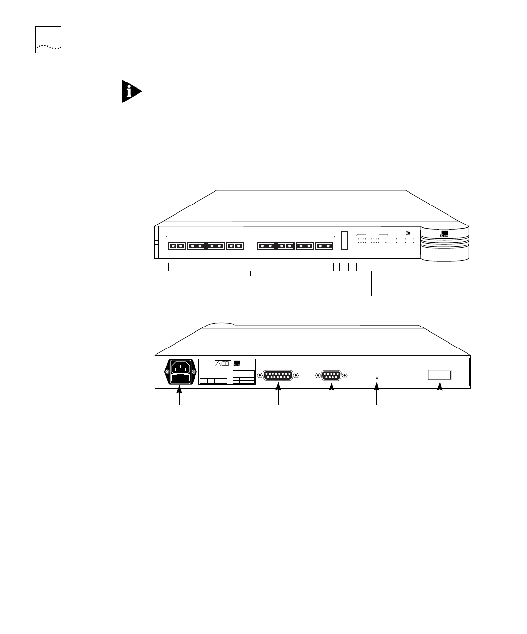
Hub Description The hub’s front and rear panels are shown in Figure 2-1.
Front panel
1
TX RX2TX RX3TX RX4TX RX
3C510-SX
1000BASE-SX downlink ports
1000BASE-SX
5
TX RX6TX RX7TX RX8TX RX
100
ACTIVITY
50
LINK
10
% BW USAGE
% BW
usage meter
PORT STATUS
1
234 5678 9
Hub operation
RPS ONOVERTEMP
SuperStack II
HUB 1000 SX
LEDs
SUPER
STACK
UNIT
STATUS
PAUSERPS FAILPWR
®
PORT STATUS
LEDs
Rear panel
AC
IN
REFER TO
INSTRUCTION MANUAL
FOR CORRECT
SELECTION OF
POWER CORD
CAUTION: For continued protection
against risk of fire use only with same
type and rating of of anti-surge fuse.
SUPPLY DATA
FUSE
2.0 AV~100-240Hz50/60A1.0
3Com Corporation
Santa Clara, CA
®
!
Made in USA
INPUT
A max58.5
DC POWER GBIC
V
+12
-12
2.5
1.0
CONSOLE
RESET
GBIC portAC input DC power Console Reset
Figure 2-1 Hub 1000 SX Front and Rear Panels
Front Panel Eight 850-nanometer (nm) fiber-optic 1000BASE-SX Gigabit Ethernet
downlink ports accept SC connectors and support 50/125 µ or
62.5/125 µ fiber-optic cable. The ports can connect to servers that
are equipped with Gigabit Ethernet NICs or to switches that are
equipped with Gigabit Ethernet uplink devices.
Indicators (see Table 2-2) show hub and port status when power is on.
Page 19

Preparing the Site 2-3
Rear Panel The AC input socket accepts a 100–240 V AC power cord. Power can
be supplied through optional 3Com SuperStack II Advanced Redundant
Power System (Advanced RPS) and SuperStack II Uninterruptible Power
System (UPS) units. These units use the DC power connector. See “Using
Optional Power Systems” later in this chapter.
The console port, a DB-9 standard male connector, can connect to a PC
through a null modem cable. For information on the console functions,
see Appendix A.
The Reset button resets the hub’s on-board CPU.
The GBIC port accepts an optional 3Com GBIC module that lets the hub
connect to a Gigabit Ethernet device.
Preparing the Site Make sure that the installation site meets the following conditions:
■ The hub is accessible and you can easily connect the cables.
■ The cables are away from:
■ Sources of electrical noise, such as: heating, ventilation,
and air conditioning (HVAC); radios; transmitters; and
broadband amplifiers
■ Power lines and fluorescent lighting fixtures
■ Water or moisture cannot enter the hub’s case.
■ Airflow around the unit and through the vents is not restricted.
Provide a minimum of 1-inch (2.5-cm) clearance on all four sides
of the unit.
■ No objects are placed directly on top of the unit.
Installing and Connecting the Hub
You can mount the hub in a standard 19-inch rack or place it on a desk
or table.
Mounting in a Rack Two brackets and four screws allow rack mounting in a standard
19-inch rack.
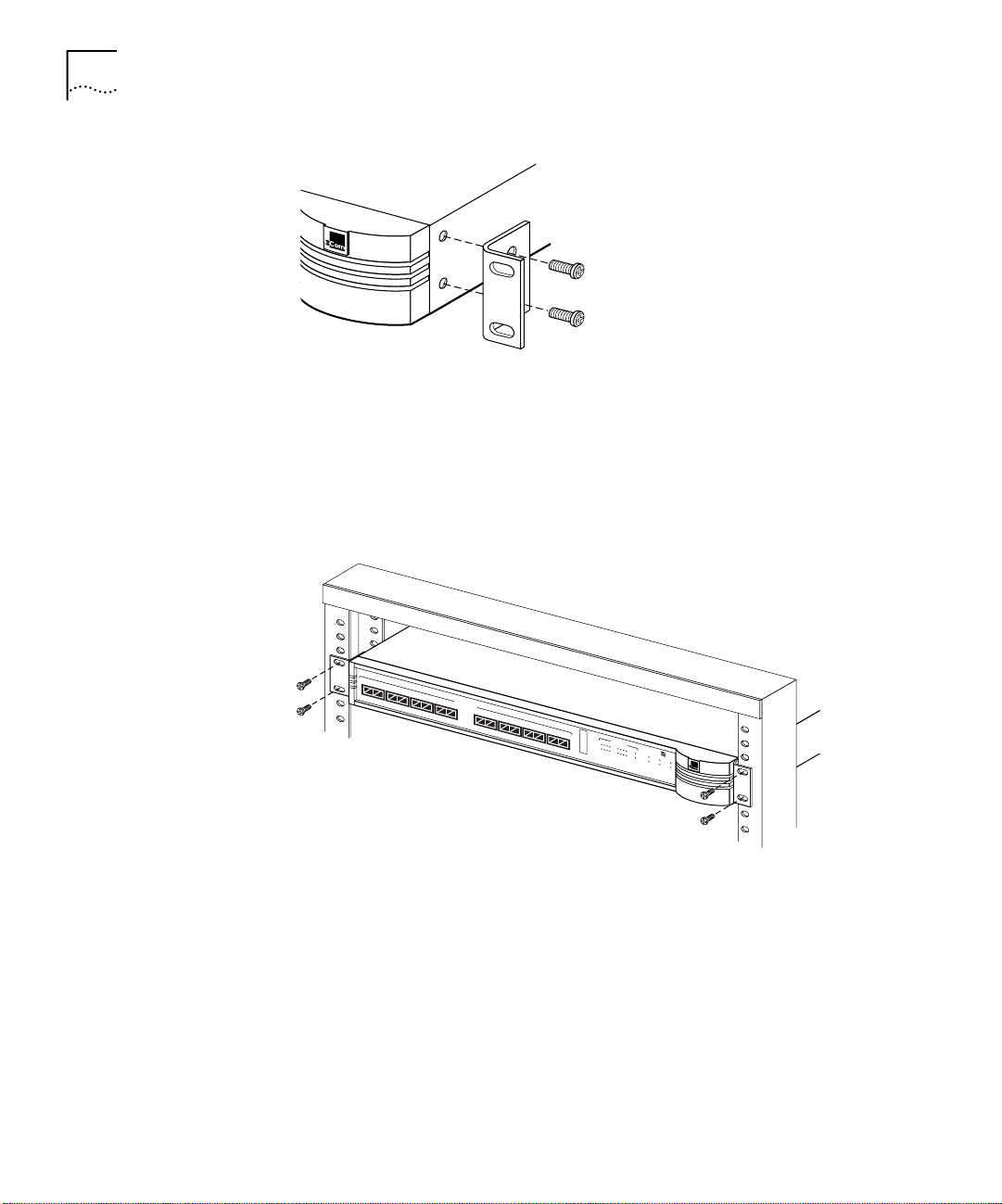
1 Place the hub on a level surface, with the front panel facing you.
2 Position a bracket over the mounting holes on one side of the hub,
as shown in Figure 2-2.
Page 20
2-4 CHAPTER 2: INSTALLING THE HUB
®
.
Figure 2-2 Attaching a Bracket for Rack Mounting
3 Insert the two screws and tighten with a screwdriver. Do not overtighten
the screws.
4 Repeat steps 2 and 3 for the other side of the hub.
5 Mount the hub in the rack and secure it with suitable screws, as shown in
Figure 2-3.
TX RX
1
TX RX
2
TX RX
3C510-SX
3
1000BASE-SX
TX RX
4
TX RX
5
TX RX
6
TX RX
7
100
TX RX
8
50
PORT STATUS
ACTIVITY
LINK
10
1
234 5678 9
% BW USAGE
SUPER
STACK
RPS ONOVERTEMP
UNIT
STATUS
PAUSERPS FAILPWR
®
SuperStack II
HUB 1000 SX
Figure 2-3 Rack Mounting the Hub
6 Remove the protective rubber cap from each downlink port and attach
the proper cable to make the desired network connection. Table 2-1
provides connector and cable information for downlink connections.
For guidelines on making typical connections, see Chapter 3.
Page 21

Table 2-1 Downlink Connections
Interpreting Hub Indicators 2-5
Connector
Type
SC Short-wavelength (850 nm) fiber-optic:
Cable Type
62.5/125 µ MMF
50/125 µ MMF
Maximum Cable
Length (Meters)
260
550
7 Apply power to the hub in either of these ways:
■ Plug one end of the power cord into the AC input socket and the
other end into a power source.
■ Connect the hub to a power supply, as described in “Using Optional
Power Systems” later in this chapter.
Placing on a Desktop If you place the hub on a desk or table, attach the supplied rubber feet to
each bottom corner of the hub. Remove the protective cap from each
downlink port and attach the proper cable to make the desired network
connection. (For connector and cable information, see Table 2-1. For
guidelines on making typical connections, see Chapter 3.) Apply power
to the hub in either of these ways:
■ Plug one end of the power cord into the AC input socket and the
other end into a power source.
■ Connect the hub to a power supply, as described in “Using Optional
Power Systems” later in this chapter.
Interpreting Hub Indicators
When power is applied, all the indicators on the front panel light
momentarily. The UNIT STATUS LED is amber while POST is running.
After approximately 30 seconds, the UNIT STATUS LED turns green.
Verify that the PWR (power) LED remains lit, indicating that the hub
is receiving power.
For explanations of the hub indicators, see Table 2-2.
Page 22

2-6 CHAPTER 2: INSTALLING THE HUB
Table 2-2 Hub 1000 SX Indicators
RPS ONOVERTEMP
SUPER
STACK
UNIT
STATUS
PAUSERPS FAILPWR
SuperStack II
HUB 1000 SX
100
50
10
% BW USAGE
PORT STATUS
ACTIVITY
LINK
1234 5678 9
Indicator Color Status Meaning
% BW usage meter Green Fluctuating The meter indicates the percentage of bandwidth that the
hub is using. Because the hub can be connected to multiple
network segments, this meter represents the aggregate
load on the hub.
PORT STATUS LEDs LEDs 1 through 8 show the status of the downlinks. LED 9
shows the status of the uplink.
ACTIVITY Green ON The port is receiving data.
OFF The port is not receiving data.
LINK Green ON A connection exists between the port and the end node.
OFF There is no connection between the port and the end node.
Hub operation LEDs
OVERTEMP Amber ON The internal temperature exceeds 158 °F (70 °C).
RPS ON Green ON The Advanced RPS is connected and turned on.
UNIT STATUS Amber ON The hub is performing POST diagnostics. If the amber LED
remains lit for longer than 30 seconds, POST has failed or
the CPU has halted.
Flashing An error has occurred.
Green ON The hub is operating normally.
Flashing A firmware update is proceeding.
Amber/Green Flashing A firmware update error occurred. See “Troubleshooting”
in Appendix A.
PWR Green ON The hub is receiving power.
RPS FAIL Amber ON The Advanced RPS is connected, but a failure
condition exists.
PAUSE Green ON The uplink port has received a pause frame. For an
explanation of pause frames, see “Flow Control” in
Chapter 1.
Page 23

Installing and Connecting a GBIC Module 2-7
Installing and
Connecting a
GBIC Module
Table 2-3 GBIC Modules
The gigabit interface connector (GBIC) port on the rear panel of the
Hub 1000 SX chassis accepts an optional 3Com GBIC module that
permits connection to a Gigabit Ethernet device. GBIC modules must
be ordered separately in either single-packs or six-packs.
By inserting the appropriate GBIC module in the hub’s rear-panel uplink
port, you can use various types of cabling to connect the hub to LAN
devices. For example, you can use the 1000BASE-LX module to reach
much greater distances than is possible with 1000BASE-SX connections.
A sample GBIC module appears in Figure 2-4. Table 2-3 lists the types of
GBIC modules available from 3Com.
Figure 2-4 Sample GBIC Module
3Com
Module Type
1000BASE-CX 3CGBIC4
1000BASE-LX 3CGBIC2
1000BASE-SX 3CGBIC1
Part Number
3CGBIC4-6PK
3CGBIC2-6PK
3CGBIC1-6PK
Connector
Type
HSSDC Shielded balanced twinaxial STP
SC Long-wavelength fiber-optic
SC Short-wavelength fiber-optic
Cable Type
(coaxial jumper)
(1300 nm):
62.5/125 µ MMF
50/125 µ MMF
SMF
(850 nm):
62.5/125 µ MMF
50/125 µ MMF
Maximum Cable
Length (Meters)
25
440
550
3000
260
550
Page 24

2-8 CHAPTER 2: INSTALLING THE HUB
To install and connect a GBIC module, follow these steps:
1 Disconnect all power to the Hub 1000 SX.
Disconnect the AC power cord. If you are using an Advanced RPS unit,
disconnect the RPS cable from the DC power connector.
2 Remove the GBIC module from its shipping container.
3 Slowly insert the module into the rear-panel uplink port, being careful not
to damage any of the components or connecting pins.
The module slides into the hub following the tracks in the slot. The
lettering that shows the module type must be positioned on top of the
connector openings when the module is in place.
4 Push the module all the way in until the connector makes contact.
5 Reattach the power cord and any power system cable to the hub.
6 Attach the proper cable to the module to make the desired
network connection.
Both ends of the connection must be of the same media type (CX, LX,
or SX).
Using Optional Power Systems
Advanced RPS A single SuperStack II Advanced RPS (part numbers 3C16070 and
7 Reconnect power to the hub.
You can ensure fail-safe operation and constant power to SuperStack II
components by using the SuperStack II Advanced Redundant
Power System (Advanced RPS) and the SuperStack II Uninterruptible
Power System (UPS). These units and associated Power Modules and
cabling must be purchased separately.
3C16071) can protect up to four SuperStack II Hub 1000 SX units from
internal power supply failures. If a SuperStack II unit’s internal power fails,
the Advanced RPS is capable of supplying all the unit’s power needs.
The Advanced RPS chassis is rack-mountable. It is fed by two independent
AC lines and remains operational if one of the AC lines fails. The front panel
provides LED indicators for monitoring temperature as well as power input
and output status.
Page 25

Using Optional Power Systems 2-9
Power Modules
At least one SuperStack II Advanced Redundant Power System
Power Module Type 2 is required for each SuperStack II hub that you
want to protect. The Hub 1000 SX requires the 100-watt, 3.3-volt version
of the module (part number 3C16074).
One Advanced RPS with Power Modules configured with straight cables for
standard usage can contain a maximum of four 100-watt Power Modules
(and four 60-watt Power Modules), or eight 60-watt Power Modules. If
each Power Module is configured for full redundancy with a SuperStack II
Advanced Redundant Power System Y Cable Type 2 (part number
3C16079), an Advanced RPS can contain a maximum of eight 100-watt
Power Modules, supporting as many as four Hub 1000 SX units.
Using the cable supplied with the Power Module, you connect the
Power Module to the DC power connector located on the rear panel
of the Hub 1000 SX. (For the DC power connector location, see
Figure 2-1.)
In the event of a failure in a Power Module, an alert is automatically
sent to the Advanced RPS management console software.
Cabling Options
You can supply AC power and DC power to the Hub 1000 SX
simultaneously, so that if an AC power failure occurs, the hub
switches to DC power supplied by the Advanced RPS unit. You can
also supply only DC power to the hub with the Advanced RPS unit.
Table 2-4 summarizes the Advanced RPS configuration options.
Page 26

2-10 CHAPTER 2: INSTALLING THE HUB
Table 2-4 Advanced RPS Configuration Options
Option Connection Description
Standard usage Disconnect the hub’s AC power cable from
the AC outlet. Use the straight DC cable
supplied with the Power Module to connect
the Power Module directly to the hub
through the DC power connector located
on the hub’s rear panel. (See “Rear Panel”
in this chapter.)
Managed redundancy Connect the hub’s AC power cable to a
standard AC outlet. Use the straight DC
cable supplied with the Power Module to
connect the Power Module directly to the
hub through the DC power connector
located on the hub’s rear panel. (See “Rear
Panel” in this chapter.)
Full redundancy Disconnect the hub’s AC power cable from
the AC outlet. Use a Y DC cable (part
number 3C16079) to connect the hub
directly to two Power Modules through the
DC power connector located on the hub’s
rear panel. (See “Rear Panel” in this chapter.)
The hub obtains DC power from a single
Power Module instead of being powered
directly from a standard AC source. If the
Power Module fails, you can swap the faulty
module for a new one. This swapping
method requires a reset of the hub, as in
a power cycle.
A cold Power Module supplies power after
about 5 seconds.
If the Hub 1000 SX internal power supply
fails, the hub’s auto-enable feature
automatically enables the Advanced RPS
and resets the hub, as in a power cycle.
This configuration offers full resilience for
mission-critical installations. The hub is
powered from both Power Modules instead
of being powered directly from a standard
AC source. If one of the Power Modules fails,
the other module takes the full load. The
faulty module can be hot-swapped,
returning the system to full redundancy
without the need for a power reset.
Uninterruptible
Power System
When switching from Advanced RPS (DC) to AC power or from AC power
to Advanced RPS power, the Hub 1000 SX unit resets itself. For example,
if both the RPS and AC cables are plugged in, and then either is removed,
the unit resets itself when it changes to the other power source.
The SuperStack II Uninterruptible Power System (UPS) (part number
3C16010, U.S. version) protects against building power outages,
brownouts, power surges, and spikes. If primary power fails or falters
for any reason, the UPS automatically provides power for as long as
7 minutes for up to four SuperStack II system units with 100-volt
50/60 Hz, 120-volt 60 Hz, or 230-volt 50/60 Hz power.
A hub connects to a UPS unit through the hub’s AC power cord.
Page 27

Using Optional Power Systems 2-11
You can connect a UPS unit to an Advanced RPS unit as long as you do
not exceed the maximum wattage (325 watts) for the UPS unit. To verify
that the UPS unit’s maximum wattage is not exceeded, calculate the total
power consumption of all units connected to the Advanced RPS. If the
result is less than 325 watts, your configuration is safe; if the result is
greater than 325 watts, then there are too many units connected to
the Advanced RPS.
To calculate the total power consumption of all units connected to the
Advanced RPS:
1 Calculate the total wattage of all the units connected to the Advanced RPS.
For example, one Hub 1000 SX has a maximum power consumption of
65 watts; two Hub 1000 SX units have a maximum power consumption
of 130 watts, and so forth.
2 Divide the total wattage of all units by 0.7, which is the efficiency rating
(70%) of the Advanced RPS.
If the result is less than 325 watts, your configuration is safe; if the result
is higher, then there are too many units connected to the Advanced RPS.
Page 28

Page 29

MAKING CONNECTIONS
3
This chapter contains guidelines for making typical Hub 1000 SX network
connections and for troubleshooting problems with the hub.
When making hub connections, follow the rules for maximum cable
lengths, which are summarized in Table 3-1. If you connect 10/100 Mbps
devices to the network, rules for Ethernet and Fast Ethernet connections
also apply.
Table 3-1 Gigabit Ethernet Maximum Cable Lengths
Cable Type
50/125 µ
Laser
Signal Type
1000BASE-SX Short
1000BASE-LX*Long
1000BASE-CX N/A HSSDC N/A N/A N/A 25 meters
* The 1000BASE-LX GBIC module requires an external patch cord for connection to MMF cable.
Wavelength
(850 nm)
(1300 nm)
Connector
Type
SC 550 meters 260 meters N/A N/A
SC 550 meters 440 meters 3 kilometers N/A
Multimode
Fiber
62.5/125 µ
Multimode
Fiber
Single-Mode
Fiber
Shielded
Balanced Pair
(Coaxial Jumper)
CAUTION: Connecting the downlink of one Hub 1000 SX to the uplink
of a second Hub 1000 SX degrades the performance of the second hub.
CAUTION: Connecting a Gigabit Ethernet switch downlink to a
Hub 1000 SX downlink degrades the performance on the link to
the switch.
Page 30

3-2 CHAPTER 3: MAKING CONNECTIONS
Aggregating Servers
You can use the Hub 1000 SX downlinks to aggregate servers into server
farms. First, install 3Com 3C985-SX Gigabit EtherLink
®
Server NICs in
each server. Then, connect up to eight servers through the downlinks.
The hub’s optional gigabit interface connector (GBIC) uplink can connect
to a 3Com SuperStack II Switch 9300 Gigabit Ethernet switch, thereby
connecting to the network backbone. See Figure 3-1.
SuperStack II
Switch 9300
SUPER
®
STACK
SuperStack II
9300 SX
Figure 3-1 Server Farm Connection
Single-mode fiber-optic cable
Maximum distance: 3 km
62.5/125 µ fiber-optic cable
Maximum distance: 260 m
Gigabit EtherLink Server NICs
SuperStack II
Hub 1000 SX
SUPER
STACK
SuperStack II
1000 SX
Servers with 3C985-SX
®
Connecting a
Power Workgroup
A power workgroup consists of a small number of servers, or a small
number of sophisticated users on high-end workstations. Such a
workgroup requires very high performance to run applications that
move and process massive amounts of data in real time (for example,
medical imaging, video editing, film postproduction, CAD/CAM, or
digital prepress).
You can provide gigabit bandwidth to a power workgroup as shown in
Figure 3-2.
Page 31

SuperStack II
Switch 9300
SUPER
®
STACK
SuperStack II
9300 SX
Single-mode fiber-optic cable
Maximum distance: 3 km
62.5/125 µ fiber-optic cable
Maximum distance: 260 m
Servers with 3C985-SX
Gigabit EtherLink Server NICs
Figure 3-2 Power Workgroup Connection
Aggregating Switches 3-3
High-end
workstations
SuperStack II
Hub 1000 SX
SUPER
®
STACK
SuperStack II
1000 SX
Aggregating Switches
You can use the Hub 1000 SX downlinks to aggregate 10/100 Mbps
switches such as the 3Com SuperStack II Switch 1000, Switch 3000,
or Switch 3900. The Switch 1000 and Switch 3000 units must be
equipped with Gigabit Ethernet uplink devices (SuperStack II Switch
Gigabit Ethernet SX Module, part number 3C16925). The Switch 3900
has one built-in Gigabit Ethernet port, which can be used to connect with
the Hub 1000 SX.
First, install 3C16925 uplink devices in the SuperStack II Switch 1000
or SuperStack II Switch 3000 switches. Then connect up to eight
switches to the Hub 1000 SX through the eight downlinks. The hub’s
optional GBIC uplink can connect to a 3Com SuperStack II Switch 9300
Gigabit Ethernet switch, thereby connecting to the network backbone.
See Figure 3-3.
The Hub 1000 SX does not support bandwidth aggregation (trunking).
Page 32

3-4 CHAPTER 3: MAKING CONNECTIONS
SuperStack II
Switch 9300
SUPER
®
STACK
SuperStack II
9300 SX
Single-mode fiber-optic cable
Maximum distance: 3 km
62.5/125 µ fiber-optic cable
Maximum distance: 260 m
SuperStack II
Hub 1000 SX
SUPER
®
STACK
SuperStack II
1000 SX
SuperStack II
®
Switch 1000
with 3C16925
uplink device
10/100 Mbps
SUPER
STACK
SuperStack II
1000 SX
SuperStack II
Switch 3900
SUPER
®
STACK
SuperStack II
3900
SuperStack II
Switch 3000
with 3C16925
uplink device
SUPER
STACK
SuperStack II
1000 SX
UTP links
Maximum distance: 100 m
Multiple 10/100 Mbps
clients
Multiple 10 Mbps
clients
Figure 3-3 Aggregated Switches Connection
Mixing Connections You can vary connections according to your requirements. For example,
you can connect a number of servers and 10/100 Mbps switches through
the downlinks, and connect to the network backbone through the
uplink, as shown in Figure 3-4.
®
Page 33

SuperStack II
Switch 9300
SUPER
STACK
SuperStack II
9300 SX
Servers with
3C985-SX Gigabit
EtherLink Server NICs
Connecting Through the Uplink 3-5
®
Single-mode fiber-optic cable
Maximum distance: 3 km
62.5/125 µ fiber-optic cable
Maximum distance: 260 m
SuperStack II
Hub 1000 SX
SUPER
®
STACK
SuperStack II
1000 SX
SuperStack II
Switch 3900
Connecting Through the Uplink
SUPER
®
STACK
SuperStack II
3900
SuperStack II
Switch 3000
with 3C16925
uplink device
SUPER
STACK
SuperStack II
1000 SX
®
SuperStack II
Switch 1000
with 3C16925
uplink device
SUPER
STACK
SuperStack II
1000 SX
10/100 Mbps
UTP links
Maximum distance: 100 m
Multiple 10/100 Mbps
clients
Multiple 10 Mbps
clients
Figure 3-4 Mixed Connection
The best use of the hub uplink is as a backbone connection to a 3Com
SuperStack II Switch 9300 Gigabit Ethernet switch, as shown earlier in
Figure 3-1 through Figure 3-2. Although two Hub 1000 SX units can be
connected to each other through their uplinks, as shown in Figure 3-5,
such a connection excludes connection to the network backbone.
Single-mode fiber-optic cable
Maximum distance: 3 km
SUPER
®
STACK
SuperStack II
1000 SX
SuperStack II
Hub 1000 SX
SUPER
®
STACK
SuperStack II
1000 SX
SuperStack II
Hub 1000 SX
®
Figure 3-5 Connection to Another Hub 1000 SX
Page 34

3-6 CHAPTER 3: MAKING CONNECTIONS
The Hub 1000 SX itself can be used as the network backbone by
connecting the uplink to a server equipped with a 3C985-SX Gigabit
EtherLink Server NIC or to a 10/100 Mbps switch equipped with a
3C16925 uplink device (see Figure 3-6). For these backbone connections,
reconfigure the uplink for asymmetric flow control, as described in
“Configuring Port Settings” in Appendix A.
Single-mode fiber-optic cable
Maximum distance: 3 km
SUPER
SuperStack II
Hub 1000 SX
®
STACK
SuperStack II
1000 SX
10/100 Mbps switch
with 3C16925 uplink device
100BASE-TX
SUPER
STACK
SuperStack II
3000 FX
Figure 3-6 Uplink Connection to a 10/100 Mbps Switch
Troubleshooting Table 3-2 summarizes some common problems and their solutions.
Table 3-2 Troubleshooting Tips
®
Symptom Explanation Solution
LINK LED does not light on
a port.
There is no link connection. You may be attempting to connect to equipment
that does not comply with Gigabit Ethernet
standards or does not support auto-negotiation.
Or, the link may be physically damaged (for example,
the cable may be damaged).
Disable auto-negotiation on the port (see Appendix A).
Configure the other end of the link for forced
configuration (see the configuration guidelines for
the device on the other end of the link). A restored
connection rules out physical damage.
ACTIVITY LED does not light
The port is not receiving data. Make sure that the link is connected at both ends.
on a port.
OVERTEMP LED is lit. The unit has overheated.
Return the unit to the supplier.
The fan may have failed.
Amber UNIT STATUS LED stays
lit longer than 30 seconds.
POST software may
be corrupted.
Use the command line interface (CLI) to confirm the
POST error. (See Appendix A.) If POST reports errors,
return the unit to the supplier.
PAUSE LED remains lit. A flickering PAUSE LED
indicates normal flow control.
Check for problems with the device attached to the
Hub 1000 SX uplink.
A PAUSE LED that remains lit
indicates that there is too
much traffic.
POST FAIL messages appear
in the CLI.
There is a fatal
hardware error.
Return the unit to the supplier.
Page 35

A
USING THE CONSOLE PORT
The Hub 1000 SX is ready to use and requires no configuration. However,
on rare occasions you may need to confirm a POST failure, change a
port’s configuration, or update the firmware image to install a bug fix or a
standards update. The console port provides access to a simple scrolling
command line interface (CLI). By connecting the console port to a PC, you
can perform these tasks:
■ Configure port settings
■ Display hub status
■ Update the firmware image
The console port (a DB-9 standard male connector) is located on the
Hub 1000 SX rear panel. See Figure A-1.
AC
IN
REFER TO
INSTRUCTION MANUAL
FOR CORRECT
SELECTION OF
POWER CORD
CAUTION: For continued protection
against risk of fire use only with same
type and rating of of anti-surge fuse.
SUPPLY DATA
FUSE
2.0 AV~100-240Hz50/60A1.0
3Com Corporation
Santa Clara, CA
®
!
Made in USA
INPUT
V
A max58.5
DC POWER GBIC
+12
-12
2.5
1.0
CONSOLE
RESET
Console
Figure A-1 Console Port
The console port default settings are:
■ 9600 baud
■ 8 data bits
■ 1 stop bit
■ No parity
Auto-baud and modem connections are not supported.
Page 36

A-2 APPENDIX A: USING THE CONSOLE PORT
Requirements To use the console port and CLI, you need:
■ A PC with a serial port
■ A null modem cable
■ A terminal-emulation program
If you need to perform a firmware update, the terminal-emulation
program must support one of these file transfer protocols: Xmodem,
Xmodem-1K, or Xmodem-CRC.
Connecting the Console Port
With Power
Connected
It is not necessary to disconnect the hub from the power source to
connect the console port. However, if you do disconnect the power,
you can watch POST messages when you reconnect the power.
To connect the console port while the hub is connected
to power:
1 Connect a null modem cable between the PC serial port and the console
port on the hub’s rear panel. (See Figure A-1.)
2 Turn on the PC.
3 Start the terminal-emulation program.
4 Configure the program with the same settings as the Hub 1000 SX
console interface port:
■ 9600 baud
■ 8 data bits
■ 1 stop bit
■ No parity
5 Press Enter.
The PC screen displays the CLI header and the password prompt:
****************************************************
* *
* SuperStack II (tm) *
* Hub 1000 SX *
* Copyright (c)1997 3Com Corporation *
* *
****************************************************
Enter password ->
Page 37

Connecting the Console Port A-3
With Power
Disconnected
To connect the console port when the hub is disconnected
from power:
1 Connect a null modem cable between the PC serial port and the
console port on the Hub 1000 SX rear panel.
2 Turn on the PC.
3 Start the terminal-emulation program.
4 Configure the program with the same settings as the Hub 1000 SX
console interface port:
■ 9600 baud
■ 8 data bits
■ 1 stop bit
■ No parity
5 Reconnect the hub to the power supply.
The PC screen displays POST messages, followed by the CLI header and
the password prompt.
POST Messages When you connect the hub to power or when you press the Reset button
on the hub’s rear panel, the PC screen displays messages while POST is
proceeding. When POST is finished, the CLI header appears, followed by
the password prompt. For example:
POST Level 0: PASS
Checking FDS ... valid.
Performing Level 1 Tests ...
Test: Port 0 - Pass.
Test: Port 1 - Pass.
Test: Port 2 - Pass.
Test: Port 3 - Pass.
Test: Port 4 - Pass.
Test: Port 5 - Pass.
Test: Port 6 - Pass.
Test: Port 7 - Pass.
Test: Port 8 - Pass.
Test: Port aliasing - Pass.
Test: MAC Address - Valid: 08004E2BA4D9
Test: Fan sense - Pass.
POST Level 1: PASS
Page 38

A-4 APPENDIX A: USING THE CONSOLE PORT
Hardware Version 0
Bootcode Version 1.00, 02/05/98
Firmware Version 1.00, 02/05/98
****************************************************
* *
* SuperStack II (tm) *
* Hub 1000 SX *
* Copyright (c)1997 3Com Corporation *
* *
****************************************************
Enter password ->
Any POST FAIL message indicates a fatal hardware error. If you see a FAIL
message, return the hub to the supplier.
Logging On The default password that is set at the factory is admin. If this is the first
time that anyone has logged on to the hub, enter the default password at
the prompt:
admin
Asterisks (*) instead of plain text appear at the prompt while you are
typing the password.
The Hub 1000 SX Configuration menu appears.
***************************************************
** Hub 1000 Configuration Menu **
***************************************************
[1] Configure port settings
[2] Display hub status
[3] Update firmware image
[4] Change password
[5] Logout
Enter choice ->
To select an option from the Configuration menu, enter the option
number at the prompt.
After 4 minutes of inactivity, the CLI logs off automatically.
Page 39

Changing the Password A-5
Changing the Password
You can change the password if you need to. The new password must be
eight characters or fewer and cannot contain spaces or tabs.
To change the password, enter:
4
You are prompted to enter the old password and then the new password,
as shown in this example:
***************************************************
** Hub 1000 Configuration Menu **
***************************************************
[1] Configure port settings
[2] Display hub status
[3] Update firmware image
[4] Change password
[5] Logout
Enter choice -> 4
Old password: *****
New password: *******
Re-enter new password: *******
Password changed.
The following sections show examples of how to use the Hub 1000 SX
Configuration menu.
Configuring
Port Settings
Table A-1 summarizes the situations that require you to configure port
settings through the Port Configuration menu.
Table A-1 Situations That Require Configuring Port Settings
Situation Action
You do not want a port to be connected. Disable the port.
A port cannot connect with a linked device. Disable auto-negotiation. (Force
A linked device does not support
auto-negotiation.
You are connecting to a server or a
10/100 Mbps switch through the uplink.
the link.)
Disable auto-negotiation. (Force
the link.)
Configure the uplink for
asymmetric flow control.
Page 40

A-6 APPENDIX A: USING THE CONSOLE PORT
To display the Port Configuration menu:
1 At the Configuration menu prompt, enter:
1
2 At the next prompt, enter the numbers of the ports that you want
to configure.
You can specify a single port number, multiple port numbers separated by
commas or spaces (for example: 5, 6 7), or a range of port numbers
separated with a hyphen (for example: 5-7).
The following example specifies ports 3, 5, 6, and 7:
***************************************************
** Hub 1000 Configuration Menu **
***************************************************
[1] Configure port settings
[2] Display hub status
[3] Update firmware image
[4] Change password
[5] Logout
Enter choice -> 1
Enter port number(s), from 1 to 9: 3 5-7
The Port Configuration menu appears, and the specified ports are
displayed. For example:
**** Port Configuration Menu ****
(1) Enable port
(2) Disable port
(3) Enable Auto-Negotiation
(4) Disable Auto-Negotiation (Force link)
(5) Show port settings
(6) Use factory default settings
(7) Save new port settings
(8) Exit without change to settings
(9) Apply changes and exit
Selected ports: 3, 5, 6, 7
Enter choice ->
Table A-2 summarizes the Port Configuration menu options.
Page 41

Configuring Port Settings A-7
Table A-2 Port Configuration Menu
Option Description
(1) Enable port Enable the port for linking. The factory
(2) Disable port Disable the port for linking.
(3) Enable auto-negotiation Enable auto-negotiation. The factory
(4) Disable auto-negotiation (force link) Disable auto-negotiation.
(5) Show port settings List the current settings for all ports.
(6) Use factory default settings Return selected ports to factory
(7) Save new port settings Save the settings. Select this option if you
(8) Exit without change to settings Exit to the Hub 1000 SX Configuration
(9) Apply changes and exit Apply the settings and exit to the
default is all ports enabled.
default is auto-negotiation enabled on
all ports.
default settings.
want settings to persist after a hub reset.
menu without applying or saving settings.
Hub 1000 SX Configuration menu.
If you want settings to persist after a hub
reset, you must select option 7 before
selecting option 9.
Disabling Ports The following example shows how to disable ports 3, 5, 6, and 7 and
apply the changes.
***************************************************
** Hub 1000 Configuration Menu **
***************************************************
[1] Configure port settings
[2] Display hub status
[3] Update firmware image
[4] Change password
[5] Logout
Enter choice -> 1
Enter port number(s), from 1 to 9: 3 5-7
**** Port Configuration Menu ****
(1) Enable port
(2) Disable port
(3) Enable Auto-Negotiation
(4) Disable Auto-Negotiation (Force link)
Page 42

A-8 APPENDIX A: USING THE CONSOLE PORT
(5) Show port settings
(6) Use factory default settings
(7) Save new port settings
(8) Exit without change to settings
(9) Apply changes and exit
Selected ports: 3, 5, 6, 7
Enter choice -> 2
**** Port Configuration Menu ****
(1) Enable port
(2) Disable port
(3) Enable Auto-Negotiation
(4) Disable Auto-Negotiation (Force link)
(5) Show port settings
(6) Use factory default settings
(7) Save new port settings
(8) Exit without change to settings
(9) Apply changes and exit
Selected ports: 3, 5, 6, 7
Enter choice -> 9
Changes applied
Disabling
Auto-Negotiation
Any time you select option 9 without selecting option 7, the settings will
return to the previous values in the event of a hub reset. This allows you
to experiment with port settings without specifying that they persist after
a hub reset. If you want settings to persist, select option 7 before
selecting option 9.
Disabling the auto-negotiation capability enables forced link on a port.
When forced link is enabled, linked devices must have matching flow
control capabilities. For example, a port that is set for forced link and
outgoing flow control can connect successfully only with a port that is
set for forced link and incoming flow control.
When you disable auto-negotiation on a Hub 1000 SX port, you also
need to set forced link on the connected device. On some devices, this
setting is called forced configuration or link negotiation. For details on
the correct configuration, see the configuration guidelines for the linked
device.
The following example shows how to disable auto-negotiation on port 1,
save the new port setting, and apply it.
Page 43

Configuring Port Settings A-9
***************************************************
** Hub 1000 Configuration Menu **
***************************************************
[1] Configure port settings
[2] Display hub status
[3] Update firmware image
[4] Change password
[5] Logout
Enter choice -> 1
Enter port number(s), from 1 to 9: 1
**** Port Configuration Menu ****
(1) Enable port
(2) Disable port
(3) Enable Auto-Negotiation
(4) Disable Auto-Negotiation (Force link)
(5) Show port settings
(6) Use factory default settings
(7) Save new port settings
(8) Exit without change to settings
(9) Apply changes and exit
Selected ports: 1
Enter choice -> 4
Enable Outgoing Flowcontrol (Y/N)? y
Port 1 is a downlink. Because downlinks support outgoing flow control only,
you can enable or disable outgoing flow control, but you cannot configure
incoming flow control. You might choose to disable outgoing flow control
if the port is linking to a device that does not support flow control.
**** Port Configuration Menu ****
(1) Enable port
(2) Disable port
(3) Enable Auto-Negotiation
(4) Disable Auto-Negotiation (Force link)
(5) Show port settings
(6) Use factory default settings
(7) Save new port settings
(8) Exit without change to settings
(9) Apply changes and exit
Selected ports: 1
Enter choice -> 7
Settings saved
Page 44

A-10 APPENDIX A: USING THE CONSOLE PORT
Because option 7 has been selected, the settings will persist after a
hub reset.
**** Port Configuration Menu ****
(1) Enable port
(2) Disable port
(3) Enable Auto-Negotiation
(4) Disable Auto-Negotiation (Force link)
(5) Show port settings
(6) Use factory default settings
(7) Save new port settings
(8) Exit without change to settings
(9) Apply changes and exit
Selected ports: 1
Enter choice -> 9
Changes applied
Configuring
the Uplink for
Asymmetric
Flow Control
The uplink (port 9) defaults to symmetric (both outgoing and incoming)
flow control. You must configure the uplink for asymmetric flow control
to connect it to a server or 10/100 Mbps switch. The server or switch
must have the appropriate NIC or uplink device, support flow control,
and be configured to receive pause frames.
The following example shows how to configure the uplink for asymmetric
flow control by disabling auto-negotiation, enabling outgoing flow
control, and disabling incoming flow control. With this configuration,
the uplink is set to forced link and can send pause frames but ignores
pause frames that it receives. (For more details on flow control, see “Flow
Control” in Chapter 1.)
***************************************************
** Hub 1000 Configuration Menu **
***************************************************
[1] Configure port settings
[2] Display hub status
[3] Update firmware image
[4] Change password
[5] Logout
Enter choice -> 1
Enter port number(s), from 1 to 9: 9
Page 45

Configuring Port Settings A-11
**** Port Configuration Menu ****
(1) Enable port
(2) Disable port
(3) Enable Auto-Negotiation
(4) Disable Auto-Negotiation (Force link)
(5) Show port settings
(6) Use factory default settings
(7) Save new port settings
(8) Exit without change to settings
(9) Apply changes and exit
Selected ports: 9
Enter choice -> 4
Enable Outgoing Flowcontrol (Y/N)? y
Enable Incoming Flowcontrol (Y/N)? n
**** Port Configuration Menu ****
(1) Enable port
(2) Disable port
(3) Enable Auto-Negotiation
(4) Disable Auto-Negotiation (Force link)
(5) Show port settings
(6) Use factory default settings
(7) Save new port settings
(8) Exit without change to settings
(9) Apply changes and exit
Selected ports: 9
Enter choice -> 7
Settings saved
Because option 7 has been selected, the settings will persist after a hub reset.
**** Port Configuration Menu ****
(1) Enable port
(2) Disable port
(3) Enable Auto-Negotiation
(4) Disable Auto-Negotiation (Force link)
(5) Show port settings
(6) Use factory default settings
(7) Save new port settings
(8) Exit without change to settings
(9) Apply changes and exit
Selected ports: 9
Enter choice -> 9
Changes applied
Page 46

A-12 APPENDIX A: USING THE CONSOLE PORT
Displaying
Hub Status
Hub status includes a matrix of information about the hub ports. In this
matrix, Y indicates yes and n indicates no. (See Table A-3.)
Table A-3 Hub Status Information
Category State Description
Port is enabled Y The port is enabled for linking.
n The port is disabled for linking.
Link state is up Y A link exists between the port and a device.
n No link exists between the port and
a device.
Auto-negotiate link
configuration
Advertise outgoing
flow control
Advertise incoming
flow control
Enable outgoing flow control Y or n If auto-negotiation is enabled, the result of
Enable incoming flow control Y or n If auto-negotiation is enabled, the result of
Y The port is set for auto-negotiation.
n The port is set for forced link.
Y The port signals outgoing flow
control capability.
n The port does not signal outgoing flow
control capability.
Y The port signals incoming flow
control capability.
n The port does not signal incoming flow
control capability.
– The port does not support incoming
flow control.
the negotiation between the port and the
linked device is shown. If auto-negotiation
is disabled, the flow control you specify
is shown.
the negotiation between the port and the
linked device is shown. If auto-negotiation
is disabled, the flow control you specify
is shown.
– The port does not support incoming
flow control.
Page 47

Displaying Hub Status A-13
Hub status also includes POST and fan status, bandwidth utilization,
hardware and firmware version, and MAC address.
The sample hub status display that follows is the result of the changes
made in the previous section. To view the hub status, enter:
2
When you have finished viewing the hub status, press Enter to continue
the CLI session.
***************************************************
** Hub 1000 Configuration Menu **
***************************************************
[1] Configure port settings
[2] Display hub status
[3] Update firmware image
[4] Change password
[5] Logout
Enter choice -> 2
Hub Status
Port Number: 1 2 3 4 5 6 7 8 9
=========== = = = = = = = = =
Port is Enabled: Y Y n Y n n n Y Y
Link state is up: Y Y n Y n n n Y Y
Auto-Negotiate link configuration: n Y Y Y Y Y Y Y n
Advertise outgoing flow control: Y Y Y Y Y Y Y Y Y
Advertise incoming flow control: - - - - - - - - n
Enable outgoing flow control: Y Y Y Y Y Y Y Y Y
Enable incoming flow control: - - - - - - - - n
Port has passed POST: Y Y Y Y Y Y Y Y Y
POST status: PASS
Fan status: Good
Bandwidth utilization: 0%
Hardware Version: 0
Firmware version: 1.00, 02/05/98
MAC Address: 08004E2BA4D9
Press Enter to continue ...
Page 48

A-14 APPENDIX A: USING THE CONSOLE PORT
Restoring the Factory Default Settings
To restore port settings to factory defaults:
1 At the Configuration menu prompt, enter:
1
2 Enter the numbers of the ports to be restored to factory defaults.
3 At the Port Configuration menu prompt, enter:
6
4 Apply the changes.
For example:
***************************************************
** Hub 1000 Configuration Menu **
***************************************************
[1] Configure port settings
[2] Display hub status
[3] Update firmware image
[4] Change password
[5] Logout
Enter choice -> 1
Enter port number(s), from 1 to 9: 1-9
**** Port Configuration Menu ****
(1) Enable port
(2) Disable port
(3) Enable Auto-Negotiation
(4) Disable Auto-Negotiation (Force link)
(5) Show port settings
(6) Use factory default settings
(7) Save new port settings
(8) Exit without change to settings
(9) Apply changes and exit
Selected ports: 1, 2, 3, 4, 5, 6, 7, 8, 9
Enter choice -> 6
Ports set to factory defaults
Page 49

Updating the Firmware Image A-15
**** Port Configuration Menu ****
(1) Enable port
(2) Disable port
(3) Enable Auto-Negotiation
(4) Disable Auto-Negotiation (Force link)
(5) Show port settings
(6) Use factory default settings
(7) Save new port settings
(8) Exit without change to settings
(9) Apply changes and exit
Selected ports: 1, 2, 3, 4, 5, 6, 7, 8, 9
Enter choice -> 9
Changes applied
If you want settings to persist after a hub reset, enter option 7 before
entering option 9.
Updating the Firmware Image
Checking the
Firmware Version
On rare occasions you may need to update the hub’s firmware image to
install a bug fix or a standards update. Firmware updates are made
available on the 3Com World Wide Web site:
http://www.3com.com/
To verify that the firmware version on the 3Com World Wide Web site
is more recent than the version installed on the hub, display the hub
status. At the Hub 1000 SX Configuration menu prompt, enter:
2
***************************************************
** Hub 1000 Configuration Menu **
***************************************************
[1] Configure port settings
[2] Display hub status
[3] Update firmware image
[4] Change password
[5] Logout
Enter choice -> 2
The firmware version is listed near the bottom of the Hub Status screen.
For example:
Firmware version: 1.00, 02/05/98
Page 50

A-16 APPENDIX A: USING THE CONSOLE PORT
Transferring the
Firmware Image File
Make sure that the terminal-emulation program supports one of
the following file transfer protocols: Xmodem, Xmodem-1K, or
Xmodem-CRC.
To transfer the firmware image file:
1 Obtain the file that contains the firmware image from the 3Com
World Wide Web site:
http://www.3com.com/
2 Copy the file to the PC.
3 Connect the console port to the PC. (See “Connecting the Console Port”
earlier in this appendix.)
4 Log on. (See “Logging On” earlier in this appendix.)
5 At the Hub 1000 SX Configuration menu prompt, enter:
3
***************************************************
** Hub 1000 Configuration Menu **
***************************************************
[1] Configure port settings
[2] Display hub status
[3] Update firmware image
[4] Change password
[5] Logout
Enter choice -> 3
The hub enters file transfer mode and prompts you to begin the
file transfer.
Please initiate XMODEM transfer now. Press <ESC> to abort.
C
The C character indicates that the hub is waiting for the
terminal-emulation program to send a file.
If you want to stop the file transfer at this point, press Esc.
6 From the terminal-emulation program, select the appropriate
command to send a file using the Xmodem, Xmodem-1K, or
Xmodem-CRC protocol.
This command varies, depending on the terminal-emulation program.
Some programs call this operation uploading a file.
Page 51

Logging Off A-17
7 When prompted, enter the filename of the firmware image file.
The terminal-emulation program begins to transfer the firmware image
file. If you want to stop the file transfer, use the appropriate command in
the terminal-emulation program.
After the transfer is finished, the CLI displays the following message:
File transfer successful.
Firmware update successful.
If the runtime software is corrupted (for example, if power is interrupted
during a firmware update), the CLI displays the following message:
Runtime image not valid.
The CLI prompts you to restart the file transfer, without requiring you to
log in again. To restart the file transfer, repeat steps 6 and 7.
Logging Off To log off the CLI, at the Hub 1000 SX Configuration menu
prompt, enter:
5
***************************************************
** Hub 1000 Configuration Menu **
***************************************************
[1] Configure port settings
[2] Display hub status
[3] Update firmware image
[4] Change password
[5] Logout
Enter choice -> 5
The screen returns to the CLI header and the password prompt.
Troubleshooting If a firmware update error occurs, the UNIT STATUS LED flashes
amber/green. Press the Reset button on the Hub 1000 SX rear panel and
repeat the procedure for updating the firmware. If the UNIT STATUS LED
continues to flash amber/green, return the unit to the supplier.
Table A-4 summarizes error messages that may appear during a file
transfer and actions you can take to correct the errors.
Page 52

A-18 APPENDIX A: USING THE CONSOLE PORT
Table A-5 lists fatal error messages. These messages indicate that the
memory unit has failed. If you see a fatal error message, return the unit
to the supplier.
Table A-4 File Transfer Error Messages
Message Meaning Action
Xmodem error: Timed out
sending NAK.
Xmodem error: Timed out
sending ACK.
Xmodem error: Timed out waiting
for packet.
Timed out waiting for transfer
to start.
Xmodem error: Got too many
errors to continue.
Xmodem error. A general protocol error occurred.
Abort key hit. Transfer aborted. The user pressed Esc to stop
Transfer aborted by file sender. The Xmodem operation in the
File too large. Transfer aborted. The file being transferred is too large
Downloaded file not valid. The firmware image file is corrupted,
The hub could not send a negative
acknowledgment.
The hub could not send an
acknowledgment.
The time limit for receiving a packet
was exceeded.
The time limit for starting the file
transfer was exceeded.
The hub error limit was exceeded.
the transfer.
terminal-emulation program stopped
the transfer.
for the hub’s memory.
or its format is incorrect.
For any of these errors, check the
following items and then restart
the transfer:
■ Make sure that the hub is in file
transfer mode (you selected
option 3 in the Hub 1000 SX
Configuration menu).
■ Make sure that you are using
the correct protocol in the
terminal-emulation program.
■ Verify that you copied the correct
file from the 3Com Web site. If
necessary, download the file from
the Web site again.
■ Check that cables are connected
properly.
■ Eliminate any interference that
may be coming from lighting or
from equipment operating near
the hub.
Table A-5 Fatal Error Messages
Message Context Action
Flash memory erase error. During firmware update. For any of these errors, return the
Flash memory programming error. During firmware update.
unit to the supplier.
Data storage error. While saving port settings or
changing the password.
System stopped! During firmware update.
Page 53

B
SPECIFICATIONS
This appendix lists the specifications for the SuperStack II Hub 1000 SX.
Physical Dimensions
Height: 4.37 cm (1.72 in.)
Width: 43.94 cm (17.3 in.)
Depth: 30.48 cm (12 in.)
Weight: 5.5 kg (12 lb)
Environmental Operating Ranges
Operating temperature: 0˚ to 50 ˚C (32˚ to 122 ˚F)
Storage temperature: –30˚ to 60 ˚C (–22˚ to 140 ˚F)
Operating humidity: 10% to 90% relative humidity, noncondensing
Storage humidity: 10% to 95% relative humidity, noncondensing
Electrostatic discharge: Does not exceed 25 kV
Operating altitude: –300 to 3000 meters (–296 to 9840 ft)
Power Requirements
AC input voltage: 90–264 V; 115–230 V nominal
Input frequency range: 47–63 Hz, single phase AC
Inrush current: 40 A peak maximum at cold start for half cycle
at any rated input voltage; no damage to the
supply from repeated on/off/on cycles under hot
or cold conditions
AC input isolation: Between primary and secondary circuits: 3000 V
Between primary circuit and chassis: 1500 V
Power consumption: 65 W maximum
Heat output: 90 BTU/hr
Fuse: Fast-blow, 250 VAC, 3.15 A, high
breaking capacity
Page 54

Page 55

C
TECHNICAL SUPPORT
3Com provides easy access to technical support information through a
variety of services. This appendix describes these services.
Information contained in this appendix is correct at time of publication.
For the very latest, we recommend that you access 3Com Corporation’s
World Wide Web site.
Online Technical Services
World Wide Web Site Access the latest networking information on 3Com Corporation’s
3Com Bulletin
Board Service
3Com offers worldwide product support 24 hours a day, 7 days a week,
through the following online systems:
■ World Wide Web site
■ 3Com Bulletin Board Service (3ComBBS)
■ 3ComFacts
■ 3ComForum on CompuServe online service
World Wide Web site by entering our URL into your Internet browser:
http://www.3com.com/
This service features the latest information about 3Com solutions and
technologies, customer service and support, news about the company,
Net Age
3ComBBS contains patches, software, and drivers for all 3Com products,
as well as technical articles. This service is available through analog
modem or digital modem (ISDN) 24 hours a day, 7 days a week.
SM
automated fax service
®
Magazine, technical documentation, and more.
Page 56

C-2 APPENDIX C: TECHNICAL SUPPORT
Access by Analog Modem
To reach the service by modem, set your modem to 8 data bits, no parity,
and 1 stop bit. Call the telephone number nearest you:
Country Data Rate Telephone Number
Australia up to 14400 bps 61 2 9955 2073
Brazil up to 14400 bps 55 11 5181 9666
France up to 14400 bps 33 1 6986 6954
Germany up to 28800 bps 4989 62732 188
Hong Kong up to 14400 bps 852 2537 5601
Italy up to 14400 bps 39 2 27300680
Japan up to 14400 bps 81 3 3345 7266
Mexico up to 28800 bps 52 5 520 7835
P.R. of China up to 14400 bps 86 10 684 92351
Taiwan, R.O.C. up to 14400 bps 886 2 377 5840
U.K. up to 28800 bps 44 1442 438278
U.S.A. up to 28800 bps 1 408 980 8204
3ComFacts
Automated
Fax Service
Access by Digital Modem
ISDN users can dial in to 3ComBBS using a digital modem for fast
access up to 56 Kbps. To access 3ComBBS using ISDN, use the
following number:
1 408 654 2703
3Com Corporation’s interactive fax service, 3ComFacts, provides data
sheets, technical articles, diagrams, and troubleshooting instructions on
3Com products 24 hours a day, 7 days a week.
Call 3ComFacts using your Touch-Tone telephone using one of these
international access numbers:
Country Telephone Number
U.K. 44 1442 438279
U.S.A. 1 408 727 7021
Page 57

Support from Your Network Supplier C-3
Local access numbers are available within the following countries:
3ComForum on
CompuServe
Online Service
Support from Your Network Supplier
Telephone
Country
Australia 1800 123 853 Netherlands 0800 0228049
Belgium 0800 71279 Norway 800 11062
Denmark 800 17319 Portugal 0505 442 607
Finland 98 001 4444 Russia (Moscow only) 956 0815
France 0800 908158 Spain 900 964 445
Germany 0130 81 80 63 Sweden 020 792954
Italy 1678 99085 U.K. 0800 626403
Number
Country
Telephone
Number
3ComForum contains patches, software, drivers, and technical articles
about all 3Com products, as well as a messaging section for peer
support. To use 3ComForum, you need a CompuServe account.
To use 3ComForum:
1 Log on to your CompuServe account.
2 Type
go threecom
3 Press [Return] to see the 3ComForum main menu.
If additional assistance is required, contact your network supplier. Many
suppliers are authorized 3Com service partners who are qualified to
provide a variety of services, including network planning, installation,
hardware maintenance, application training, and support services.
When you contact your network supplier for assistance, have the
following information ready:
■ A list of system hardware and software, including revision levels
■ Diagnostic error messages
■ Details about recent configuration changes, if applicable
If you are unable to contact your network supplier, see the following
section on how to contact 3Com.
Page 58

C-4 APPENDIX C: TECHNICAL SUPPORT
Support from 3Com If you are unable to receive support from your network supplier, technical
support contracts are available from 3Com.
Contact your local 3Com sales office to find your authorized service
provider using one of these numbers:
Regional Sales Office Telephone Number
3Com Corporation
P.O. Box 58145
5400 Bayfront Plaza
Santa Clara, California
95052-8145
U.S.A.
3Com Asia Limited
Australia
Hong Kong
India
Indonesia
Japan
Korea
Malaysia
New Zealand
Philippines
P.R. of China
Singapore
Taiwan, R.O.C.
Thailand
3Com Austria 43 1 580 17 0
3Com Benelux B.V.
Belgium
Netherlands
3Com Canada
Calgary
Edmonton
Montreal
Ottawa
Toronto
Vancouver
3Com France 33 1 69 86 68 00
3Com GmbH
Czech Republic/Slovak
Republic
800 NET 3Com
61 2 9937 5000 (Sydney)
61 3 9866 8022 (Melbourne)
852 2501 1111
91 11 644 3974
62 21 572 2088
81 6 536 3303 (Osaka)
81 3 3345 7251 (Tokyo)
82 2 3455 6300
60 3 732 7910
64 9 366 9138
632 892 4476
8610 68492568 (Beijing)
86 21 63501581 (Shanghai)
65 538 9368
886 2 377 5850
662 231 8151 5
32 2 725 0202
31 0346 586211
403 265 3266
403 423 3266
514 683 3266
613 566 7055
416 498 3266
604 434 3266
420 2 21845 800
Regional Sales Office Telephone Number
3Com GmbH (cont’d)
Germany
(Central European HQ)
Hungary
Poland
3Com Iberia
Portugal
Spain
3Com Latin America
U.S. Headquarters
Northern Latin America
Argentina
Brazil
Chile
Colombia
Mexico
Peru
Venezuela
3Com Mediterraneo
Italy
3Com Middle East 971 4 349049
3Com Nordic AB
Denmark
Finland
Norway
Sweden
3Com Russia 007 095 258 09 40
3Com Southern Africa 27 11 807 4397
3Com Switzerland 41 31 996 14 14
3Com Technologies
Ireland
3Com U.K. Ltd. 44 131 240 2900 (Edinburgh)
49 30 34 98790 (Berlin)
49 89 627320 (Munich)
36 1 250 83 41
48 22 6451351
351 1 3404505
34 1 5096900
408 326 2093
305 261 3266 (Miami, Florida)
541 312 3266
55 11 5181 0869
562 633 9242
57 1 629 4847
52 5 520 7841/7847
51 1 221 5399
58 2 953 8122
39 2 253011 (Milan)
39 6 5279941 (Rome)
45 39 27 85 00
358 0 435 420 67
47 22 58 47 00
46 8 632 56 00
353 1 820 7077
44 161 873 7717 (Manchester)
44 1628 897000 (Marlow)
Page 59

Returning Products for Repair C-5
Returning Products for Repair
Before you send a product directly to 3Com for repair, you must first
obtain a Return Materials Authorization (RMA) number. Products sent to
3Com without RMA numbers will be returned to the sender unopened,
at the sender’s expense.
To obtain an RMA number, call or fax:
Country Telephone Number Fax Number
U.S.A. and Canada 1 800 876 3266, option 2 408 764 7120
Latin America 1 408 326 2927 408 764 7120
Europe, South Africa, and
Middle East
Elsewhere 1 408 326 2926 1 408 764 7120
44 1442 435860 44 1442 435822
Page 60

Page 61

GLOSSARY
10BASE-T The IEEE 802.3 physical layer specification for a 10 Mbps Ethernet
network over two pairs of Category 3, 4, or 5 UTP wire.
100BASE-T The group of IEEE 802.3 physical layer specifications for a 100 Mbps
Ethernet network over various wiring specifications.
1000BASE-X The group of IEEE 802.3 physical layer specifications for a 1000 Mbps
Ethernet network over various wiring specifications.
1000BASE-CX The IEEE 802.3 physical layer specification for a 1000 Mbps Ethernet
network over short-haul shielded balanced copper cable (known as
twinaxial STP).
1000BASE-LX The IEEE 802.3 physical layer specification for a 1000 Mbps Ethernet
network over long laser wavelength (1300 nm) multimode fiber (MMF)
or single-mode fiber (SMF) cable.
1000BASE-SX The IEEE 802.3 physical layer specification for a 1000 Mbps Ethernet
network over short laser wavelength (850 nm) MMF or SMF cable.
Advanced RPS 3Com SuperStack II Advanced Redundant Power System.
asymmetric
flow control
auto-negotiation A method by which linked devices advertise their signaling capabilities
backbone The main transmission medium used to interconnect the workgroup
A relationship between linked network devices in which only one of the
devices can receive pause frames. See also flow control, pause frame,
symmetric flow control.
(such as protocol, speed, media type, and flow control capabilities) and
automatically select their best common mode of communication.
areas of a network. Fiber-optic cable is often used for the backbone
connection.
Page 62

2 GLOSSARY
bidirectional
See symmetric flow control.
flow control
CSMA/CD Carrier Sense Multiple Access/Collision Detection. Channel access
method used by Ethernet and IEEE 802.3 in which devices transmit only
after finding the data channel clear for some period. When two devices
transmit simultaneously, a collision occurs and the colliding devices
delay their retransmissions for a random length of time.
Ethernet A local area network standard defining a physical medium and its
method of placing data, or packet signaling, on a cable. Access to the
cable is based on CSMA/CD (Carrier Sense Multiple Access/Collision
Detection).
Fast Ethernet A 100 Mbps technology based on the Ethernet CSMA/CD network
access method.
fiber-optic cable Cable consisting of a glass center, cladding, a buffer layer, strength
members, and a cable sheath. The glass center supports the
transmission of light signals.
flow control A method for ensuring that a transmitting entity does not overwhelm a
receiving entity with data. See also asymmetric flow control, incoming
flow control, outgoing flow control, pause frame, symmetric flow
control.
forced link A method by which devices link with fixed and matching signaling
capabilities. See also auto-negotiation.
full-duplex The ability of a device or line to transmit data simultaneously in both
directions. See also half-duplex.
Gigabit Ethernet A 1000 Mbps network technology that retains support for
10/100 Mbps Ethernet CSMA/CD networks.
half-duplex Data transmission that can occur in two directions over a single line,
but in only one direction at a time. See also full-duplex.
hub A device used to provide connectivity between network devices. Hubs
perform the basic repeater functions of restoring signal amplitude and
timing, detecting collisions, and broadcasting signals to network
devices. See also repeater.
Page 63

GLOSSARY 3
IEEE Institute of Electrical and Electronics Engineers. Committees that
develop and propose computer standards, such as the 802 protocols,
which define the physical and data link protocols of communication
networks. Members represent an international cross section of users,
vendors, and engineering professionals.
incoming
flow control
The ability of a device to receive pause frames. See symmetric
flow control.
LAN Local area network. An assembly of computing resources such as PCs,
printers, minicomputers, and mainframe computers linked by a
common transmission medium, such as UTP.
LED Light-emitting diode. A diode that converts voltage to light and that is
commonly used in digital displays.
MAC Media Access Control. The data link sublayer that is responsible for
transferring data to and from the physical layer.
Mbps Megabits per second.
outgoing
flow control
The ability of a device to send pause frames. See Asymmetric
flow control.
partition A repeater function that isolates a particular port from the network
because of an excessive number of collisions. Once the problem
causing the collisions is corrected, the port is reactivated.
pause frame A set of bits that tells a transmitting device to stop the transmission of
data frames for a specified period or to resume the transmission of
data frames.
power workgroup A small number of servers or a small number of sophisticated users
on high-end workstations. A power workgroup requires very high
performance to run applications that move and process massive
amounts of data in real time (for example, medical imaging, video
editing, film postproduction, CAD/CAM, or digital prepress).
repeater A device that extends the length, topology, or interconnectivity of
the physical medium beyond that imposed by a single segment, up
to the maximum allowable end-to-end trunk transmission line length.
Repeaters perform the basic actions of restoring signal amplitude,
waveform, and timing applied to normal data and collision signals.
See also hub.
Page 64

4 GLOSSARY
SuperStack 3Com system of stackable hubs, servers, switches, routers, SDLC
SC A fiber-optic cable connector. When it is pushed into place, the
connector is seated automatically.
STP Shielded twisted-pair. Shielded four-conductor electrical cable that
offers high-speed transmission for long distances.
converters, and power supplies. SuperStack systems can support a
range of LAN environments, including Ethernet, token ring, FDDI,
SNA, and ATM.
symmetric
flow control
A relationship between linked network devices in which both devices
can send and receive pause frames. Also called bidirectional flow
control. See also asymmetric flow control, flow control, pause frame.
twisted-pair Wiring similar to that found in the telephone system, consisting of two
insulated wires loosely twisted around each other to help cancel out
induced noise in balanced circuits.
UTP Unshielded twisted-pair. A cable consisting of two or more pairs of
twisted copper wires that are not shielded.
Page 65

INDEX
Symbols
% BW usage meter 2-6
Numbers
1000BASE-CX 1-2
1000BASE-LX 1-2
1000BASE-SX 1-2
1000BASE-X cables and connectors 3-1
3C16925 Gigabit Ethernet SX uplink module 3-3
3C985-SX Gigabit EtherLink Server NIC 3-2
3Com Bulletin Board Service (3ComBBS) C-1
3Com sales offices C-4
3Com URL C-1
3ComFacts C-2
3ComForum C-3
A
AC
ACTIVITY LED 2-6
Advanced Redundant Power System (RPS) 2-3, 2-8
aggregating devices
asymmetric flow control 3-6
auto-negotiation
2-9
power
power cord 2-1, 2-3
cabling options 2-9
calculating power for 2-11
configuration options 2-10
Power Modules 2-9
3-2
servers
switches 3-3
definition 1-3
1-3
defined
disabling A-8
B
backbone 1-2, 3-2, 3-5
bandwidth aggregation 3-3
bidirectional flow control 1-3
bulletin board service C-1
C
cables 2-5, 2-7, 2-9, 3-1
calculating power consumption for Advanced
2-11
RPS
carrier integrity monitor 1-4
command line interface (CLI) A-1
CompuServe C-3
configuration 1-1, A-1
auto-negotiation 1-3
forced link A-8
configuring port settings A-5
connections
console port
downlink 2-5
guidelines 3-1
power workgroup 3-2
uplink 3-5
console interface (CLI) A-1
console port 2-3, A-1
connecting A-2
requirements A-2
conventions
notice icons, About This Guide
text, About This Guide 2
conventions, notice icons, About This Guide 1
CSMA/CD 1-1
A-2
1
D
DC power 2-9
default port configuration settings, restoring A-14
desktop placement of hub 2-5
disabling a port A-7
displaying hub status A-13
downlinks 1-2, 2-2
aggregating servers 3-2
aggregating switches 3-3
cabling 2-5
connections 2-5
flow control 1-3
Page 66

2 INDEX
E
environmental operating ranges B-1
F
factory defaults, restoring port configuration A-14
fax service (3ComFacts) C-2
firmware image, updating A-15
flow control 1-2, A-10
flow control, auto-negotiation 1-3
forced link 1-3, A-8
frames
front panel 2-2
full redundancy for Advanced RPS 2-10
full resilience 2-10
full-duplex operation 1-2
fuse B-1
1-4
aging
pause 1-2
G
GBIC (gigabit interface connector) modules 1-2, 2-7
cabling 2-7
connections 3-2
connector types 2-7
installation 2-8
GBIC port 2-3
Gigabit Ethernet
maximum cable lengths
technology, definition 1-1
uplink module 3-3
3-1
H
hub
connections
desktop placement 2-5
features and functions 1-4
front panel 2-2
indicators and LEDs 2-6
installation 2-3
rack mounting 2-3
rear panel 2-3
status A-12, A-13
hub operation LEDs 2-6
3-1
I
IEEE specifications
incoming flow control 1-2
1-2
802.3x
802.3z 1-4
indicators
at power on
descriptions 2-6
installation
GBIC module
hub desktop placement 2-5
hub rack mounting 2-3
2-5
2-8
J
jabber control 1-4
L
LED
descriptions
indicators 1-4
LINK LED 2-6
2-6
M
managed redundancy for Advanced RPS 2-10
maximum cable length 2-7
downlink connections 2-5
Gigabit Ethernet 3-1
maximum wattage, for UPS 2-11
media access control 1-4
N
network supplier support C-3
O
online technical services C-1
operating voltage requirements B-1
optional power systems 2-8
outgoing flow control 1-2
OVERTEMP LED 2-6
P
pause frames 1-2
PAUSE LED 2-6
physical dimensions B-1
port
access, round-robin
disabling A-7
GBIC 2-3
reconfiguration A-5
asymmetric flow control A-10
restoring factory defaults A-14
Port Configuration menu A-6
PORT STATUS LEDs 2-6
1-2, 1-4
Page 67

INDEX 3
POST
description
diagnostics 2-6
messages A-3
power
requirements
systems, optional 2-8
power consumption calculation for Advanced
2-11
RPS
Power Modules 2-9, 2-10
power on 2-5
power workgroup 3-2
power-on self-test (POST)
description
diagnostics 2-6
messages A-3
PWR (power) LED 2-6
1-4
B-1
1-4
R
rack mounting
instructions for
kit 2-1
rear panel 2-3
reconfiguring ports A-5
redundancy, for Advanced RPS
2-10
full
managed 2-10
redundant power system configuration 2-10
requirements
console port
power B-1
resilience, full 2-10
returning products for repair C-5
round-robin port access 1-2, 1-4
RPS FAIL LED 2-6
RPS ON LED 2-6
2-3
A-2
SuperStack II
Advanced Redundant Power System (RPS)
Advanced RPS Power Module 2-9
Hub 1000 SX. See hub
Switch 1000
Switch 3000 3-3
Switch 3900 3-3
Switch 9300 3-2, 3-3, 3-5
Uninterruptible Power System (UPS) 1-1, 2-8, 2-10
switches, aggregating 3-3
symmetric flow control 1-3
3-3
1-1, 2-8
T
technical support
3Com URL
bulletin board service C-1
CompuServe service C-3
fax service C-2
network suppliers C-3
product repair C-5
troubleshooting 3-6
trunking 3-3
C-1
U
Uninterruptible Power System (UPS) 2-8, 2-10
maximum wattage 2-11
UNIT STATUS LED 2-6
updating firmware A-15
uplink 1-2, 2-3
backbone connection 3-2, 3-3
connections 2-7, 3-5
flow control 1-3, 3-6
reconfiguring for asymmetric flow control A-10
uses 1-2
URL C-1
S
safety precautions 2-1
server farms 3-2
servers, aggregating 3-2
signal retiming 1-4
site preparation 2-3
specifications B-1
environmental operating ranges B-1
physical dimensions B-1
power requirements B-1
standard usage for Advanced RPS 2-10
status, hub A-13
W
World Wide Web (WWW) C-1
X
Xmodem protocol A-2, A-16
Y
Y cable 2-10
Page 68

Page 69

3Com Corporation LIMITED WARRANTY
+5 Limited Warranty
The duration of the warranty for the SuperStack II Hub 1000 SX is five (5) years, with the exception of the product’s fans and power supplies, which
are warranted for the first year only. Advance hardware replacement will be provided for one (1) year from your date of purchase, in accordance with
3Com’s standard terms and conditions. An extension of the advance replacement coverage is available through the purchase of a service agreement. To
qualify for the five year warranty and one year of advance hardware replacement, you must submit your warranty registration card to 3Com. If you do
not submit your warranty registration card, the products will be covered by 3Com’s standard one year warranty.
HARDWARE 3Com warrants its hardware products to be free from defects in workmanship and materials, under
normal use and service, for the following lengths of time from the date of purchase from 3Com or its
Authorized Reseller:
Network interface cards Lifetime
Other hardware products (unless otherwise specified in the warranty statement above) 1 year
Spare parts and spares kits 90 days
If a product does not operate as warranted above during the applicable warranty period, 3Com shall, at its
option and expense, repair the defective product or part, deliver to Customer an equivalent product or part
to replace the defective item, or refund to Customer the purchase price paid for the defective product.
All products that are replaced will become the property of 3Com. Replacement products may be new or
reconditioned. Any replaced or repaired product or part has a ninety (90) day warranty or the remainder
of the initial warranty period, whichever is longer.
3Com shall not be responsible for any software, firmware, information, or memory data of Customer
contained in, stored on, or integrated with any products returned to 3Com for repair, whether under
warranty or not.
SOFTWARE 3Com warrants that the software programs licensed from it will perform in substantial conformance to the
program specifications therefor for a period of ninety (90) days from the date of purchase from 3Com or
its Authorized Reseller. 3Com warrants the media containing software against failure during the warranty
period. No updates are provided. The sole obligation of 3Com with respect to this express warranty shall
be (at the discretion of 3Com) to refund the purchase price paid by Customer for any defective software
products, or to replace any defective media with software which substantially conforms to applicable 3Com
published specifications. Customer assumes responsibility for the selection of the appropriate applications
program and associated reference materials. 3Com makes no warranty or representation that its software
products will work in combination with any hardware or applications software products provided by
third parties, that the operation of the software products will be uninterrupted or error free, or that all
defects in the software products will be corrected. For any third-party products listed in the 3Com software
product documentation or specifications as being compatible, 3Com will make reasonable efforts to provide
compatibility, except where the noncompatibility is caused by a “bug” or defect in the third party’s product.
STANDARD WARRANTY
S
ERVICE
Standard warranty service for hardware products may be obtained by delivering the defective product,
accompanied by a copy of the dated proof of purchase, to the 3Com Corporate Service Center or to an
Authorized 3Com Service Center during the applicable warranty period. Standard warranty service for
software products may be obtained by telephoning the 3Com Corporate Service Center or an Authorized
3Com Service Center, within the warranty period. Products returned to the 3Com Corporate Service Center
must be preauthorized by 3Com with a Return Material Authorization (RMA) number marked on the outside
of the package, and sent prepaid, insured, and packaged appropriately for safe shipment. The repaired or
replaced item will be shipped to Customer, at the expense of 3Com, not later than thirty (30) days after
receipt of the defective product by 3Com.
WARRANTIES EXCLUSIVE IF A 3COM PRODUCT DOES NOT OPERATE AS WARRANTED ABOVE, CUSTOMER’S SOLE REMEDY FOR
BREACH OF THAT WARRANTY SHALL BE REPAIR, REPLACEMENT, OR REFUND OF THE PURCHASE PRICE
PAID, AT THE OPTION OF 3COM. TO THE FULL EXTENT ALLOWED BY LAW, THE FOREGOING WARRANTIES
AND REMEDIES ARE EXCLUSIVE AND ARE IN LIEU OF ALL OTHER WARRANTIES, TERMS, OR CONDITIONS,
EXPRESS OR IMPLIED, EITHER IN FACT OR BY OPERATION OF LAW, STATUTORY OR OTHERWISE, INCLUDING
WARRANTIES, TERMS, OR CONDITIONS OF MERCHANTABILITY, FITNESS FOR A PARTICULAR PURPOSE, AND
SATISFACTORY QUALITY. 3COM NEITHER ASSUMES NOR AUTHORIZES ANY OTHER PERSON TO ASSUME
FOR IT ANY OTHER LIABILITY IN CONNECTION WITH THE SALE, INSTALLATION, MAINTENANCE, OR USE OF
ITS PRODUCTS.
3COM SHALL NOT BE LIABLE UNDER THIS WARRANTY IF ITS TESTING AND EXAMINATION DISCLOSE THAT
THE ALLEGED DEFECT IN THE PRODUCT DOES NOT EXIST OR WAS CAUSED BY CUSTOMER’S OR ANY THIRD
PERSON’S MISUSE, NEGLECT, IMPROPER INSTALLATION OR TESTING, UNAUTHORIZED ATTEMPTS TO REPAIR
OR MODIFY, OR ANY OTHER CAUSE BEYOND THE RANGE OF THE INTENDED USE, OR BY ACCIDENT, FIRE,
LIGHTNING, OR OTHER HAZARD.
Page 70

LIMITATION OF LIABILITY TO THE FULL EXTENT ALLOWED BY LAW, 3COM ALSO EXCLUDES FOR ITSELF AND ITS SUPPLIERS ANY
LIABILITY, WHETHER BASED IN CONTRACT OR TORT (INCLUDING NEGLIGENCE), FOR INCIDENTAL,
CONSEQUENTIAL, INDIRECT, SPECIAL, OR PUNITIVE DAMAGES OF ANY KIND, OR FOR LOSS OF REVENUE
OR PROFITS, LOSS OF BUSINESS, LOSS OF INFORMATION OR DATA, OR OTHER FINANCIAL LOSS ARISING
OUT OF OR IN CONNECTION WITH THE SALE, INSTALLATION, MAINTENANCE, USE, PERFORMANCE, FAILURE,
OR INTERRUPTION OF ITS PRODUCTS, EVEN IF 3COM OR ITS AUTHORIZED RESELLER HAS BEEN ADVISED OF
THE POSSIBILITY OF SUCH DAMAGES, AND LIMITS ITS LIABILITY TO REPAIR, REPLACEMENT, OR REFUND OF
THE PURCHASE PRICE PAID, AT THE OPTION OF 3COM. THIS DISCLAIMER OF LIABILITY FOR DAMAGES WILL
NOT BE AFFECTED IF ANY REMEDY PROVIDED HEREIN SHALL FAIL OF ITS ESSENTIAL PURPOSE.
GOVERNING LAW This Limited Warranty shall be governed by the laws of the State of California, U.S.A. Some countries, states,
or provinces do not allow the exclusion or limitation of implied warranties or the limitation of incidental or
consequential damages for certain products supplied to consumers or the limitation of liability for personal
injury, so the above limitations and exclusions may be limited in their application to you. This warranty gives
you specific legal rights which may vary depending on local law.
3Com Corporation, 5400 Bayfront Plaza, Santa Clara, CA 95052-8145 (408) 764-5000
FCC CLASS A VERIFICATION STATEMENT
WARNING: This equipment has been tested and found to comply with the limits for a Class A digital device,
pursuant to Part 15 of the FCC Rules, and the Canadian Department of Communications Equipment
Standards entitled, “Digital Apparatus,” ICES-003. These limits are designed to provide reasonable protection
against harmful interference in a commercial installation. This equipment generates, uses and can radiate
radio frequency energy and, if not installed and used in accordance with the instructions, may cause harmful
interference to radio communications. Operation of this equipment in a residential area is likely to cause
harmful interference, in which case, the user will be required to correct the interference at the user’s
own expense.
Changes or modifications not expressly approved by 3Com could void the user’s authority to operate
this equipment.
 Loading...