

Page 1

H3C MSR 20/30/50 Series Routers
Interface Card and
Interface Module Manual
(v1.00)
www.3Com.com
Part Number: 10016325 Rev. AA
August 2007
Page 2

3Com Corporation
350 Campus Drive
Marlborough, MA
USA 01752-3064
Copyright © 2007, 3Com Corporation. All rights reserved. No part of this documentation may be reproduced in any form or
by any means or used to make any derivative work (such as translation, transformation, or adaptation) without written
permission from 3Com Corporation.
3Com Corporation reserves the right to revise this documentation and to make changes in content from time to time
without obligation on the part of 3Com Corporation to provide notification of such revision or change.
3Com Corporation provides this documentation without warranty, term, or condition of any kind, either implied or
expressed, including, but not limited to, the implied warranties, terms or conditions of merchantability, satisfactory quality,
and fitness for a particular purpose. 3Com may make improvements or changes in the product(s) and/or the program(s)
described in this documentation at any time.
If there is any software on removable media described in this documentation, it is furnished under a license agreement
included with the product as a separate document, in the hard copy documentation, or on the removable media in a
directory file named LICENSE.TXT or !LICENSE.TXT. If you are unable to locate a copy, please contact 3Com and a copy will
be provided to you.
UNITED STATES GOVERNMENT LEGEND
If you are a United States government agency, then this documentation and the software described herein are provided to
you subject to the following:
All technical data and computer software are commercial in nature and developed solely at private expense. Software is
delivered as “Commercial Computer Software” as defined in DFARS 252.227-7014 (June 1995) or as a “commercial item”
as defined in FAR 2.101(a) and as such is provided with only such rights as are provided in 3Com’s standard commercial
license for the Software. Technical data is provided with limited rights only as provided in DFAR 252.227-7015 (Nov 1995) or
FAR 52.227-14 (June 1987), whichever is applicable. You agree not to remove or deface any portion of any legend provided
on any licensed program or documentation contained in, or delivered to you in conjunction with, this User Guide.
Unless otherwise indicated, 3Com registered trademarks are registered in the United States and may or may not be
registered in other countries.
3Com and the 3Com logo are registered trademarks of 3Com Corporation.
H3C, , Aolynk, , H3Care, , TOP G, , IRF, NetPilot, Neocean, NeoVTL, SecPro,
SecPoint, SecEngine, SecPath, Comware, Secware, Storware, NQA, VVG, V2G, VnG, PSPT, XGbus, N-Bus, TiGem, InnoVision
and HUASAN are trademarks of Hangzhou H3C Technologies Co., Ltd., a 3Com company.
All other trademarks that may be mentioned in this manual are the property of their respective owners.
ENVIRONMENTAL STATEMENT
It is the policy of 3Com Corporation to be environmentally-friendly in all operations. To uphold our policy, we are committed
to:
Establishing environmental performance standards that comply with national legislation and regulations.
Conserving energy, materials and natural resources in all operations.
Reducing the waste generated by all operations. Ensuring that all waste conforms to recognized environmental standards.
Maximizing the recyclable and reusable content of all products.
Ensuring that all products can be recycled, reused and disposed of safely.
Ensuring that all products are labelled according to recognized environmental standards.
Improving our environmental record on a continual basis.
End of Life Statement
3Com processes allow for the recovery, reclamation and safe disposal of all end-of-life electronic components.
Regulated Materials Statement
3Com products do not contain any hazardous or ozone-depleting material.
Environmental Statement about the Documentation
The documentation for this product is printed on paper that comes from sustainable, managed forests; it is fully
biodegradable and recyclable, and is completely chlorine-free. The varnish is environmentally-friendly, and the inks are
vegetable-based with a low heavy-metal content.
Page 3

CONTENTS
ABOUT THIS GUIDE
Conventions 7
Related Documentation 8
1 OVERVIEW
SIC/DSIC Interface Cards 9
MIM/DMIM/XMIM 10
FIC/DFIC Interface Cards 13
SIC/MIM/FIC Purchase Guideline 15
Installation/Removal of a SIC/MIM/FIC 16
Troubleshooting 19
2 SMART INTERFACE CARDS
SIC-1FEA 21
SIC-1SAE 23
SIC-1EPRI/SIC-1E1-F 28
SIC-1TPRI/SIC-1T1-F 33
SIC-1AM/SIC-2AM 36
SIC-1FXS/SIC-1FXO & SIC-2FXS/SIC-2FXO 37
SIC-4FSW/SIC-4FSW-PoE/DSIC-9FSW/DSIC-9FSW-PoE 39
SIC-1GEC 42
SIC-1VE1 45
SIC-1VT1 49
SIC-1ADSL 51
SIC-1ADSL-I 53
SIC-1BS/SIC-2BS&SIC-1BU/SIC-2BU 55
SIC-1BSV/SIC-2BSV 58
SIC-1FEF 61
SIC-8AS 63
3 MULTIFUNCTIONAL INTERFACE MODULES
MIM-1FE/MIM-2FE/MIM-4FE Modules 67
MIM-1GBE/MIM-2GBE Module 69
MIM-1GEF/MIM-2GEF Module 71
MIM-2SAE/MIM-4SAE/MIM-8SAE Module 74
MIM-8ASE/MIM-16ASE Module 79
MIM-1E1/MIM-2E1/MIM-4E1/MIM-1E1-F/MIM-2E1-F/MIM-4E1-F Modules 81
Page 4

MIM-8E1/MIM-8E1-F Module 89
MIM-1T1/MIM-2T1/MIM-4T1/MIM-1T1-F/MIM-2T1-F/MIM-4T1-F Modules 91
MIM-8T1/MIM-8T1-F Module 95
MIM-1CE3 Module 97
MIM-1CT3 Module 98
MIM-4BSE Module 100
MIM-1G.SHDSL 104
MIM-1AMM/MIM-1ASM/MIM-1ASL 105
MIM-1AE3 Module 107
MIM-1AT3 Module 109
MIM-1POS Module 110
MIM-2FXS/MIM-2FXO/MIM-2E&M and MIM-4FXS/MIM-4FXO/MIM-4E&M 112
MIM-HNDE Module 116
MIM-2VE1 Module 117
MIM-2VT1 Module 120
MIM-1VE1 Module 122
MIM-1VT1 Module 125
MIM-16FSW/MIM-16FSW-PoE/DMIM-24FSW/DMIM-24FSW-PoE 127
MIM-IMA-4E1/MIM-IMA-8E1 Module 131
MIM-IMA-4T1/MIM-IMA-8T1 Module 134
MIM-2BSV/MIM-4BSV Module 136
MIM-1CPOS Module 139
MIM-1SHL-4W Module 141
XMIM-16FSW/XMIM-24FSW 143
4 FLEXIBLE INTERFACE CARDS
FIC-1FE/FIC-2FE/FIC-4FE 147
FIC-1GBE/FIC-2GBE 149
FIC-1GEF/FIC-2GEF 151
FIC-2SAE/FIC-4SAE/FIC-8SAE 153
FIC-8ASE/FIC-16ASE 159
FIC-1E1/FIC-2E1/FIC-4E1 and FIC-1E1-F/FIC-2E1-F/FIC-4E1-F 161
FIC-8E1/FIC-8E1-F 169
FIC-1T1/FIC-2T1/FIC-4T1 and FIC-1T1-F/FIC-2T1-F/FIC-4T1-F 172
FIC-8T1/FIC-8T1-F 176
FIC-1CE3 178
FIC-1CT3 180
FIC-4BSE 181
FIC-1AE3 185
FIC-1AT3 186
FIC-1ATM-OC3MM/FIC-1ATM-OC3SM/ FIC-1ATM-OC3SML 188
FIC-1G.SHDSL 190
FIC-1POS 191
FIC-2FXS/FIC-2FXO/FIC-2E&M and FIC-4FXS/FIC-4FXO/FIC-4E&M 193
FIC-HNDE 197
FIC-2VE1 199
FIC-2VT1 202
Page 5

FIC-1VE1 204
FIC-1VT1 206
FIC-16FSW/FIC-16FSW-PoE/DFIC-24FSW/DFIC-24FSW-PoE 208
FIC-IMA-4E1/FIC-IMA-8E1 212
FIC-IMA-4T1/FIC-IMA-8T1 215
FIC-1SHL-4W 217
FIC-1CPOS 218
FIC-2BSV/FIC-4BSV Module 221
FIC-24FXS 224
DFIC-24FXO24FXS 226
5 ESM/VCPM MODULE
ANDE Module 229
SNDE Module 230
VCPM Module 231
A INTERFACE CARD AND INTERFACE MODULE PURCHASE GUIDE
SIC/DSIC Purchase Guide 235
MIM/DMIM Purchase Guide 236
FIC/DFIC Purchase Guide 238
ESM/VPM/VCPM Purchase Guide 239
Page 6

Page 7

ABOUT THIS GUIDE
This guide describes the various interface cards and interface modules that are
available for use with you H3C MSR 20/30/50 Series router.
This guide is intended for qualified service personnel who are responsible for
configuring, using, and managing the routers. It assumes a working knowledge of
local area network (LAN) operations and familiarity with communication protocols
that are used to interconnect LANs.
n
Conventions Table 1 lists icon conventions that are used throughout this guide.
Always download the Release Notes for your product from the 3Com World Wide
Web site and check for the latest updates to software and product
documentation: http://www.3Com.com
Tab l e 1 Notice Icons
Icon Notice Type Description
Information note Information that describes important features or
n
Caution Information that alerts you to potential loss of data
c
Warning Information that alerts you to potential personal
w
Table 2 lists text conventions that are used throughout this guide.
Tab l e 2 Text Conventions
Convention Description
Screen displays This typeface represents information as it appears on the
Keyboard key names If you must press two or more keys simultaneously, the key
The words “enter” and “type” When you see the word “enter” in this guide, you must type
instructions.
or potential damage to an application, system, or
device.
injury.
screen.
names are linked with a plus sign (+), for example:
Press Ctrl+Alt+Del
something, and then press Return or Enter. Do not press
Return or Enter when an instruction simply says “type.”
Page 8

8 ABOUT THIS GUIDE
Tab le 2 Text Conventions
Convention Description
Words in italics Italics are used to:
Emphasize a point.
Denote a new term at the place where it is defined in the
text.
Identify menu names, menu commands, and software
button names.
Examples:
From the Help menu, select Contents.
Click OK.
Words in bold Boldface type is used to highlight command names. For
example, “Use the display user-interface command
to...”
Related Documentation
The following manuals offer additional information necessary for managing your
MSR 20/30/50 Series router:
■ H3C MSR 20/30/50 Series Routers Installation Manuals — Covers setting up
and initializing your router.
■ H3C MSR 20/30/50 Series Routers Configuration Guide — Describes how to
operate the router. It includes sections about getting started, system
management, interface, link layer protocol, network protocol, routing protocol,
multicast protocol, security, VPN, reliability, QoS, dial-up and VoIP, as well as
acronyms used in the manual.
■ H3C MSR 20/30/50 Series Routers Command Reference Guide — Provides a
detailed description of the operating commands. It includes sections about
getting started, system management, interface, link layer protocol, network
protocol, routing protocol, multicast protocol, security, VPN, reliability, QoS,
dial-up and VoIP, as well as a command index.
■ LMR Series Routers Cable Manual — Describes the pinouts of the cables
available for LMR series routers.
■ Release Notes — Contains the latest information about your product. If
information in this guide differs from information in the release notes, use the
information in the Release Notes.
These documents are available in Adobe Acrobat Reader Portable Document
Format (PDF) on the CD-ROM that accompanies your router or on the 3Com
World Wide Web site: http://www.3Com.com
Page 9

1
OVERVIEW
This manual covers three broad categories of interface cards and modules
available with MSR Series Routers: smart interface card/double smart interface
card (SIC/DSIC), multiplex interface module/double multiplex interface
module/expand multiplex interface module (MIM/DMIM/XMIM), and flexible
interface card/double flexible interface card (FIC/DFIC).
SIC/DSIC Interface Cards
Ethernet interface cards 1-port 10/100/1000 Mbps electrical and fiber interface card (SIC-1GEC)
WAN interface cards 1-port enhanced high-speed synchronous/asynchronous serial interface card
Currently, the following types of SIC/DSIC interface cards are available.
1-port 10Base-T/100Base-TX Ethernet interface card (SIC-1FEA)
1-port 100 Mbps fiber Ethernet interface card (SIC-1FEF)
4-port 10/100 Mbps Ethernet Layer 2 switching interface card (SIC-4FSW)
9-port 10/100 Mbps Ethernet Layer 2 switching interface card (DSIC-9FSW)
4-port 10/100 Mbps Ethernet Layer 2 switching PoE interface card (SIC-4FSW-POE)
9-port 10/100 Mbps Ethernet Layer 2 switching PoE interface card
(DSIC-9FSW-POE)
(SIC-1SAE)
8-port asynchronous serial interface card (SIC-8AS)
1-port E1/CE1/PRI compatible interface card (SIC-1EPRI)
1-port fractional E1 interface card (SIC-1E1-F)
1-port T1/CT1/PRI compatible interface card (SIC-1TPRI)
1-port fractional T1 interface card (SIC-1T1-F)
1-port analog modem interface card (SIC-1AM)
2-port analog modem interface card (SIC-2AM)
1-port ADSL interface card (SIC-1ADSL)
1-port ADSL over ISDN interface card (SIC-1ADSL-I)
Page 10

10 CHAPTER 1: OVERVIEW
1-port ISDN BRI S/T interface card (SIC-1BS)
2-port ISDN BRI S/T interface card (SIC-2BS)
1-port ISDN BRI U interface card (SIC-1BU)
2-port ISDN BRI U interface card (SIC-2BU)
Voice interface cards 1-port voice subscriber circuit interface card (SIC-1FXS)
2-port voice subscriber circuit interface card (SIC-2FXS)
1-port voice AT0 analog trunk interface card (SIC-1FXO)
2-port voice AT0 analog trunk interface card (SIC-2FXO)
1-port CE1/PRI/R2 compatible interface card (SIC-1VE1)
1-port CT1/PRI compatible interface card (SIC-1VT1)
1-port ISDN BRI S/T voice interface card (SIC-1BSV)
2-port ISDN BRI S/T voice interface card (SIC-2BSV)
MIM/DMIM/XMIM H3C MSR 30 series routers provide MIM slots and support the following
MIM/DMIM/XMIM:
Ethernet modules 1-port 10Base-T/100Base-TX Fast Ethernet interface module (MIM-1FE)
2-port 10Base-T/100Base-TX Fast Ethernet interface module (MIM-2FE)
4-port 10Base-T/100Base-TX Fast Ethernet interface module (MIM-4FE)
1-port 10Base-T/100Base-TX/1000Base-T Ethernet electrical interface module
(MIM-1GBE)
2-port 10Base-T/100Base-TX/1000Base-T Ethernet electrical interface module
(MIM-2GBE)
1-port 1000Base-SX/1000Base-LX gigabit Ethernet fiber interface module
(MIM-1GEF)
2-port 1000Base-SX/1000Base-LX gigabit Ethernet fiber interface module
(MIM-2GEF)
16-port 10/100 Mbps Layer 2 switching interface module (MIM-16FSW)
24-port 10/100 Mbps Layer 2 switching interface module (DMIM-24FSW)
16-port 10/100 Mbps Ethernet Layer 2 switching PoE interface module
(DMIM-16FSW-POE)
24-port 10/100 Mbps Ethernet Layer 2 switching PoE interface module
(DMIM-24FSW-POE)
Page 11

MIM/DMIM/XMIM 11
16-port 10/100 Mbps Ethernet Layer 2 switching interface module (XMIM-16FSW)
24-port 10/100 Mbps Ethernet Layer 2 switching interface module (XMIM-24FSW)
WAN modules 2-port enhanced high-speed synchronous/asynchronous serial interface module
(MIM-2SAE)
4-port enhanced high-speed synchronous/asynchronous serial interface module
(MIM-4SAE)
8-port enhanced high-speed synchronous/asynchronous serial interface module
(MIM-8SAE)
8-port enhanced asynchronous serial interface module (MIM-8ASE)
16-port enhanced asynchronous serial interface module (MIM-16ASE)
1-port channelized E1 interface module (MIM-1E1)
2-port channelized E1 interface module (MIM-2E1)
4-port channelized E1 interface module (MIM-4E1)
8-port channelized E1 interface module (MIM-8E1)
1-port fractional E1 interface module (MIM-1E1-F)
2-port fractional E1 interface module (MIM-2E1-F)
4-port fractional E1 interface module (MIM-4E1-F)
8-port fractional E1 interface module (MIM-8E1-F)
1-port channelized T1 interface module (MIM-1T1)
2-port channelized T1 interface module (MIM-2T1)
4-port channelized T1 interface module (MIM-4T1)
8-port channelized T1 interface module (MIM-8T1)
1-port fractional T1 interface module (MIM-1T1-F)
2-port fractional T1 interface module (MIM-2T1-F)
4-port fractional T1 interface module (MIM-4T1-F)
8-port fractional T1 interface module (MIM-8T1-F)
1-port channelized E3 interface module (MIM-1CE3)
1-port channelized T3 interface module (MIM-1CT3)
4-port ISDN BRI S/T interface module (using jumpers) (MIM-4BSE)
1-port G.SHDSL interface module (MIM-1G.SHDSL)
Page 12

12 CHAPTER 1: OVERVIEW
1-port ATM 155 Mbps multi-mode fiber interface module (MIM-1AMM)
1-port ATM 155 Mbps single-mode fiber interface module (MIM-1ASM)
1-port ATM 155 Mbps single-mode long-haul fiber interface module (MIM-1ASL)
1-port 34 Mbps ATM-E3 interface module (MIM-1AE3)
1-port 44 Mbps ATM-T3 interface module (MIM-1AT3)
8-port E1 ATM inverse multiplexing interface module (MIM-IMA-8E1)
4-port E1 ATM inverse multiplexing interface module (MIM-IMA-4E1)
8-port T1 ATM inverse multiplexing interface module (MIM-IMA-8T1)
4-port T1 ATM inverse multiplexing interface module (MIM-IMA-4T1)
1-port SDH/SONET interface module (MIM-1POS)
1-port channelized SDH/SONET interface module (E1) (MIM-1CPOS (E))
1-port channelized SDH/SONET interface module (T1) (MIM-1CPOS (T))
1-port dual-pair G.SHDSL interface module (MIM-SHL-4W)
Voice modules 2-port voice subscriber circuit interface module (MIM-2FXS)
2-port voice AT0 analog trunk interface module (MIM-2FXO)
2-port voice E&M analog trunk interface module (MIM-2E&M)
4-port voice subscriber circuit interface module (MIM-4FXS)
4-port voice AT0 analog trunk interface module (MIM-4FXO)
4-port voice E&M analog trunk interface module (MIM-4E&M)
1-port E1 voice interface module (MIM-1VE1)
1-port T1 voice interface module (MIM-1VT1)
2-port E1 voice interface module (MIM-2VE1)
2-port T1 voice interface module (MIM-2VT1)
2-port ISDN BRI S/T voice interface module (MIM-2BSV)
4-port ISDN BRI S/T voice interface module (MIM-4BSV)
Encryption modules Network data encryption module (NDEC)
High-performance network data encryption module (HNDE)
Page 13

FIC/DFIC Interface Cards 13
FIC/DFIC Interface Cards
Ethernet interface cards 1-port 10Base-T/100Base-TX FE interface card (FIC-1FE)
The following are the FIC/DFIC interface cards available with MSR 50 Series
Routers:
2-port 10Base-T/100Base-TX FE interface card (FIC-2FE)
4-port 10Base-T/100Base-TX FE interface card (FIC-4FE)
1-port 10Base-T/100Base-TX/1000Base-T GE electrical interface card (FIC-1GBE)
2-port 10Base-T/100Base-TX/1000Base-T GE electrical interface card (FIC-2GBE)
1-port 1000Base-SX/1000Base-LX GE fiber interface card (FIC-1GEF)
2-port 1000Base-SX/1000Base-LX GE fiber interface card (FIC-2GEF)
16-port 10/100 Mbps Layer 2 switching interface card (FIC-16FSW)
24-port 10/100 Mbps Layer 2 switching interface card (DFIC-24FSW)
16-port 10/100 Mbps Ethernet Layer 2 switching PoE interface module
(FIC-16FSW-POE)
24-port 10/100 Mbps Ethernet Layer 2 switching PoE interface module
(DFIC-24FSW-POE)
WAN interface cards 2-port enhanced multiprotocol synchronous/asynchronous serial interface card
(FIC-2SAE)
4-port enhanced multiprotocol synchronous/asynchronous serial interface card
(FIC-4SAE)
8-port enhanced multiprotocol synchronous/asynchronous serial interface card
(FIC-8SAE)
4-port ISDN BRI S/T interface card (using jumpers) (FIC-4BSE)
8-port enhanced asynchronous serial interface card (FIC-8ASE)
16-port enhanced asynchronous serial interface card (FIC-16ASE)
1-port channelized T1/PRI interface card (FIC-1T1)
2-port channelized T1/PRI interface card (FIC-2T1)
4-port channelized T1/PRI interface card (FIC-4T1)
8-port channelized T1/PRI interface card (FIC-8T1)
1-port fractional T1 interface card (FIC-1T1-F)
2-port fractional T1 interface card (FIC-2T1-F)
Page 14

14 CHAPTER 1: OVERVIEW
4-port fractional T1 interface card (FIC-4T1-F)
8-port fractional T1 interface card (FIC-8T1-F)
1-port channelized E1/PRI interface card (FIC-1E1)
2-port channelized E1/PRI interface card (FIC-2E1)
4-port channelized E1/PRI interface card (FIC-4E1)
8-port channelized E1/PRI interface card (FIC-8E1)
1-port fractional E1 interface card (FIC-1E1-F)
2-port fractional E1 interface card (FIC-2E1-F)
4-port fractional E1 interface card (FIC-4E1-F)
8-port fractional E1 interface card (FIC-8E1-F)
1 port channelized T3 interface card (FIC-1CT3)
1-port channelized E3 interface card (FIC-1CE3)
1-port ATM 155 Mbps multi-mode fiber interface card (FIC-1ATM-OC3MM)
1-port ATM 155 Mbps single-mode fiber interface card (FIC-1ATM-OC3SM)
1-port ATM 155 Mbps single-mode long-haul fiber interface card
(FIC-1ATM-OC3SML)
1-port 34 Mbps ATM-E3 interface card (FIC-1AE3)
1-port 44 Mbps ATM-T3 interface card (FIC-1AT3)
1-port G.SHDSL interface card (FIC-1G.SHDSL)
1-port dual-pair G.SHDSL interface card (FIC-1SHL-4W)
8-port E1 ATM inverse multiplexing interface card (FIC-IMA-8E1)
4-port E1 ATM inverse multiplexing interface card (FIC-IMA-4E1)
8-port T1 ATM inverse multiplexing interface card (FIC-IMA-8T1)
4-port T1 ATM inverse multiplexing interface card (FIC-IMA-4T1)
1-port channelized SDH/SONET interface card (FIC-1CPOS (E))
1-port channelized SDH/SONET interface card (FIC-1CPOS (T))
1-port SDH/SONET interface card (FIC-1POS)
Page 15

SIC/MIM/FIC Purchase Guideline 15
Voice interface cards 2-port voice subscriber circuit interface card (FIC-2FXS)
2-port voice AT0 analog trunk interface card (FIC-2FXO)
2-port voice E&M analog trunk interface card (FIC-2E&M)
4-port voice subscriber circuit interface card (FIC-4FXS)
4-port voice AT0 analog trunk interface card (FIC-4FXO)
4-port voice E&M analog trunk interface card (FIC-4E&M)
1-port E1 voice interface card (FIC-1VE1)
1-port T1 voice interface card (FIC-1VT1)
2-port E1 voice interface card (FIC-2VE1)
2-port T1 voice interface card (FIC-2VT1)
2-port ISDN BRI S/T voice interface card (MIM-2BSV)
Encryption cards High-performance network data encryption card (FIC-HNDE)
SIC/MIM/FIC Purchase Guideline
4-port ISDN BRI S/T voice interface card (MIM-4BSV)
24-port voice subscriber circuit interface card (FIC-24FXS)
24-port voice subscriber circuit interface card & 24-port voice AT0 analog trunk
interface card (DFIC-24FXO24FXS)
Data encryption card
You may equip an H3C series router with appropriate interface cards or modules
and are allowed to:
■ Install multiple interface cards or modules of the same type on the router;
■ Install an interface card or module in any slot on the router, disregarding its
type.
Also, you should:
■ Select interface cable appropriate to each interface card or module;
■ See “Interface Card and Interface Module Purchase Guide” on page 235 for
the full capacity specifications appropriate to your router model;
n
■ See “Interface Card and Interface Module Purchase Guide” on page 235 for
the interface cards and modules you are allowed to select.
The VE1 module, the VT1 module, and the 12AM module are 1U in height, each
occupying two slots.
Page 16
16 CHAPTER 1: OVERVIEW
Installation/Removal of a SIC/MIM/FIC
w
c
Installing/Removing a
SIC
WARNING: H3C MSR 20/30 Series Routers do not support online insertion and
removal of SICs and MIMs. Before implementing any of the following operations,
wear an anti-static wrist strap and ESD-preventive glove, and make sure that the
power of the Router has been turned off and the power cord has been
unplugged. Otherwise, you may get an electric shock or your router may get
damaged.
CAUTION: When replacing/installing an interface card or module, note the
following
■ Do not damage the EMI gaskets on the card/module panel. They can filter
electromagnetic interference of the router.
■ To protect the card or module against ESD damage, hold the card/module by
its edge and do not touch the components on the circuit board. Put the
uninstalled interface card or module on an antistatic tray.
■ If you do not install a new card or module after removing the old one, replace
the blank filter panel to keep off the dust and ensure adequate ventilation of
the router.
Tools required
■ Flat-module screwdriver
■ ESD-preventive wrist strap and ESD-preventive glove
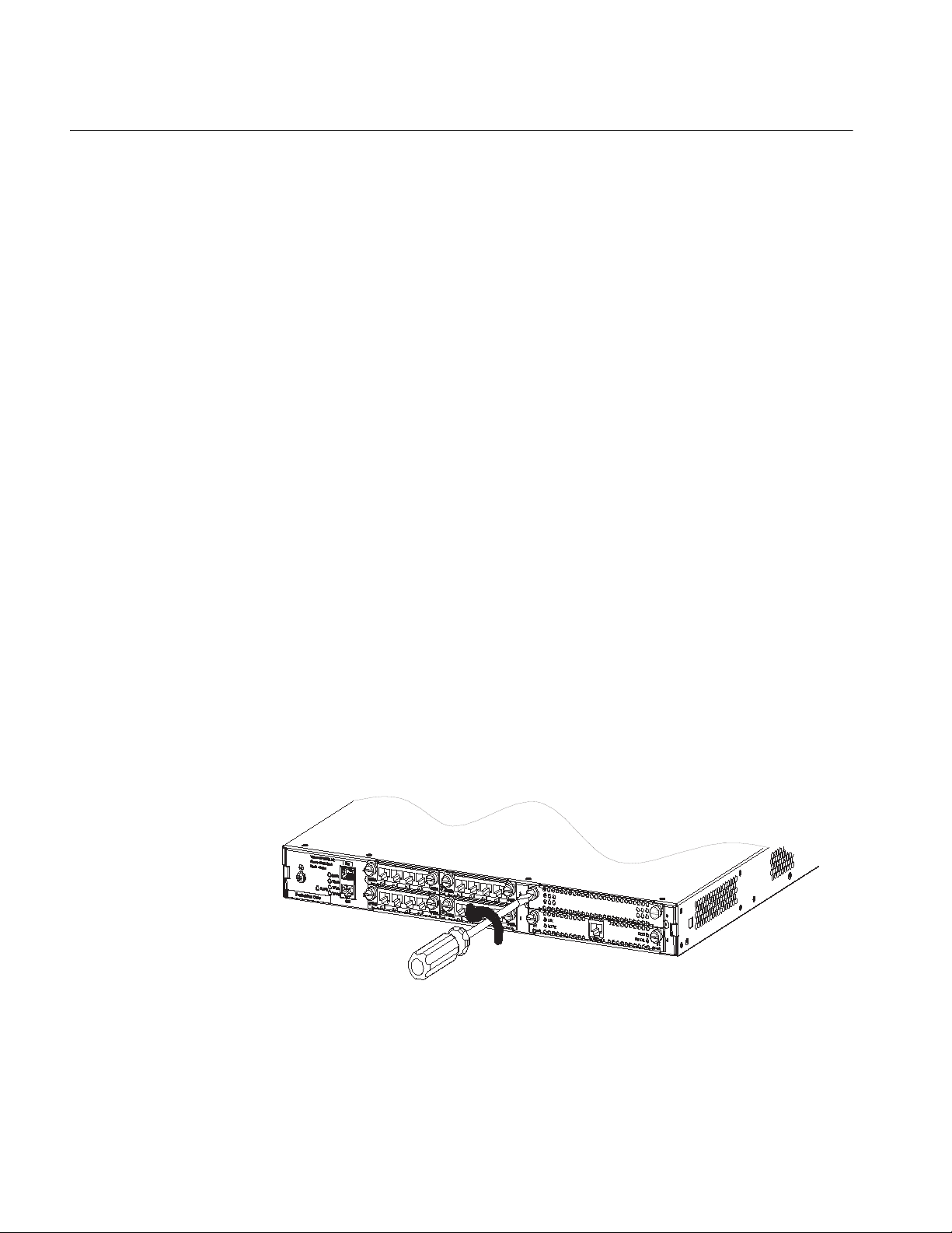
Removing the blank filler panel in a SIC slot
Take the MSR 30 for example. Following the rotating direction shown in this
figure, remove the captive screws of the blank filler panel using the flat-module
screwdriver.
Figure 1 Removing the blank filler panel from a SIC slot
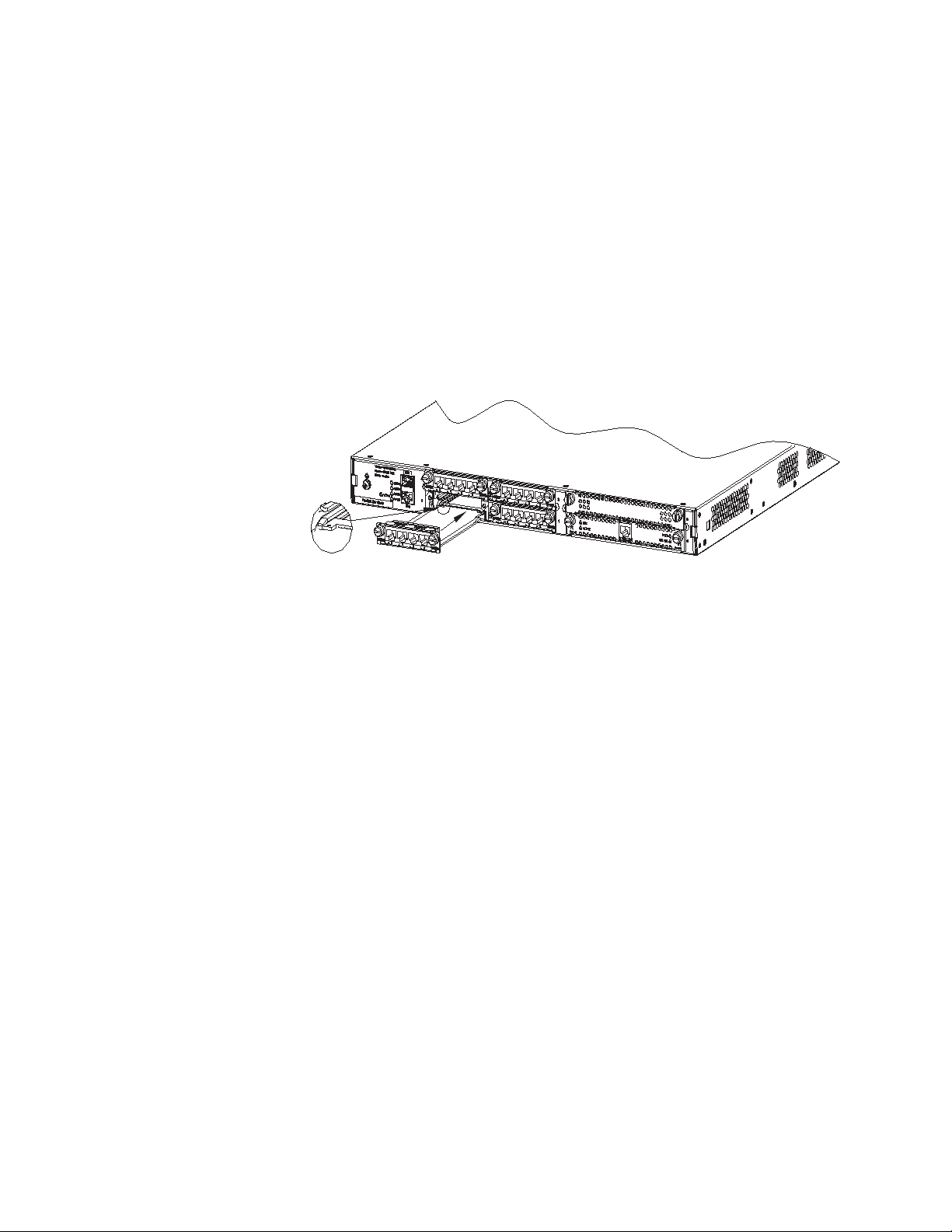
Installing a SIC
Follow these steps to install a SIC:
Step 1: Place the rear panel of the Router towards you;
Step 2: Turn off the power switch of the Router and unplug the power cord;
Page 17
Installation/Removal of a SIC/MIM/FIC 17
Step 3: Take out the SIC and align its remote edge with the edge of the slot on the
Router’s rear panel;
Step 4: Push the SIC into the Router until it closely mates with the rear panel of
the Router;
Step 5: Fasten the SIC into the Router with captive screws;
Step 6: Power on the Router, and check the LEDs of the corresponding slot on the
front panel: after the initialization of the SIC, ON means that the SIC is operating
normally and OFF means that its Power-On Self-Test (POST) has failed. In the latter
case, please contact your agent.
Figure 2 Installing SIC
Installing/Removing a
MIM
Removing a SIC
Follow these steps to remove a SIC:
Step 1: Place the rear panel of the Router towards you;
Step 2: Turn off the power switch of the Router and unplug the power cord;
Step 3: Unplug all the network interface cables connected to the rear panel of the
Router;
Step 4: Remove the captive screws on both sides of the SIC using the flat-module
screwdriver;
Step 5: Pull the SIC outward until it is completely taken out of the Router chassis.
Tools required
■ Flat-module screwdriver
■ ESD-preventive wrist strap and ESD-preventive glove
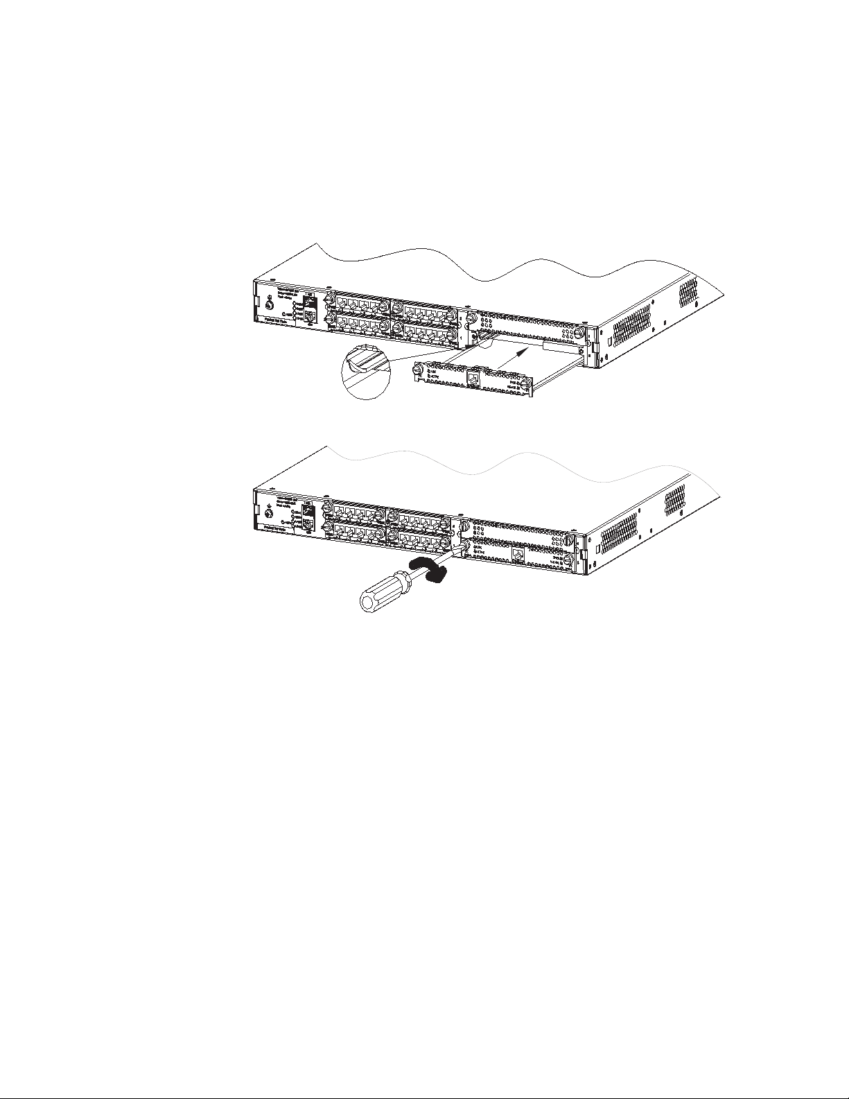
Installing a MIM
Follow these steps to install a MIM:
Step 1: Place the rear panel of the Router towards you;
Step 2: Turn off the power switch of the Router and unplug the power cord;
Step 3: Select a slot and insert the MIM along the guides in the slot until it
contacts the rear panel of the Router;
Page 18
18 CHAPTER 1: OVERVIEW
Step 4: Fix the MIM into the Router with captive screws;
Step 5: Power on the Router, and check the LEDs of the corresponding slot on the
front panel: ON means that the MIM is operating normally and OFF means that
the POST of the MIM has failed. In the latter case, please contact your agent.
Figure 3 Installing a MIM (1)
Figure 4 Installing a MIM (2)
Installing/Removing a
FIC
c
Removing a MIM
Follow these steps to remove a MIM:
Step 1: Place the rear panel of the Router towards you;
Step 2: Turn off the power switch of the Router and unplug the power cord;
Step 3: Unplug all interface cables from the rear panel of the Router;
Step 4: Loosen the captive screws at both sides of the MIM;
Step 5: Pull the MIM towards you until it is completely separated from the bottom
of the router.
CAUTION: The EMI gaskets on the FIC panel can filter electromagnetic
interference of the router. Do not damage them when uninstalling or replacing an
FIC.
If you do not install a new FIC after removing the old one, replace the blank filter
panel to keep off the dust and ensure adequate ventilation of the router.
Page 19

Troubleshooting 19
The MSR 50 series supports hot swapping. Thus, you can remove or install FICs
when the router is running without disconnecting the power supply. But before
that, you must first execute the remove slot command; otherwise, unknown
errors might occur. When you replace the removed FICs, you do not need to
execute the undo remove slot command however.
If you execute the remove slot command inadvertently, you can cancel that
operation by using the undo remove slot command.
Tools required
■ ESD-preventive wrist strap
Removing a FIC
Step 1: Place the router with the front panel forward.
Step 2: Remove the cables connected to the FIC.
Step 3: Loosen the captive screws at both sides of the FIC.
Step 4: Push the ejector levers at both sides of the FIC outward, pull the FIC out of
the slot along the guides until disengaging it totally from the slot.
Installing a FIC
Step 1: Place the router with the front panel forward.
Step 2: Align the remote edge of the FIC with the slot edge, push it into the slot,
push the ejector levers inward until it presses against the FIC panel (the angles
thus formed between the FIC panel and the levers are the minimum angles).
Step 3: Fix the FIC in the chassis by fastening the captive screws.
Repeat these steps to install all the other FICs.
Troubleshooting H3C Series Routers provide LEDs, thus facilitating you to make sure whether a
SIC/MIM/FIC is properly installed by viewing their state as follows:
After the installation of a SIC/MIM/FIC, turn on the power and view the
corresponding LEDs on the cover of the Router chassis: ON means that the
SIC/MIM/FIC is operating normally and OFF means that the Power-On Self-Test
(POST) of the SIC/MIM/FIC has failed.
If the installed SIC/MIM/FIC is in abnormal state, check that:
■ Proper interface cable is used;
■ The LEDs on the panel of SIC/MIM/FIC are displaying normally (see the section
introducing the SIC/MIM/FIC for its LED status and description);
■ The SIC/MIM/FIC accepts the configuration and works well using the display
command.
Page 20

20 CHAPTER 1: OVERVIEW
Page 21

2
SMART INTERFACE CARDS
MSR series routers adopt modular design and support a wide range of optional
smart interface cards (SICs) and double smart interface cards (DSICs). A SIC
interface card occupies one SIC slot of an MSR router and a DSIC interface card
occupies two SIC slots of a router. The SIC/DSIC series interface cards provide
abundant interfaces, such as synchronous/asynchronous serial interface, Ethernet
interface, E1/T1, ISDN BRI/PRI, ADSL, audio interface, Layer 2 switching interface,
and so on.
Among this series interface cards, the Layer 2 switching interface cards (SIC-4FSW
and DSIC-9FSW) each have a corresponding PoE-capable one, which can provide
-48 VDC power to remote powered devices (PDs, such as IP phone, WLAN AP,
network camera) through straight-through cables as long as installed in a PoE
router.
n
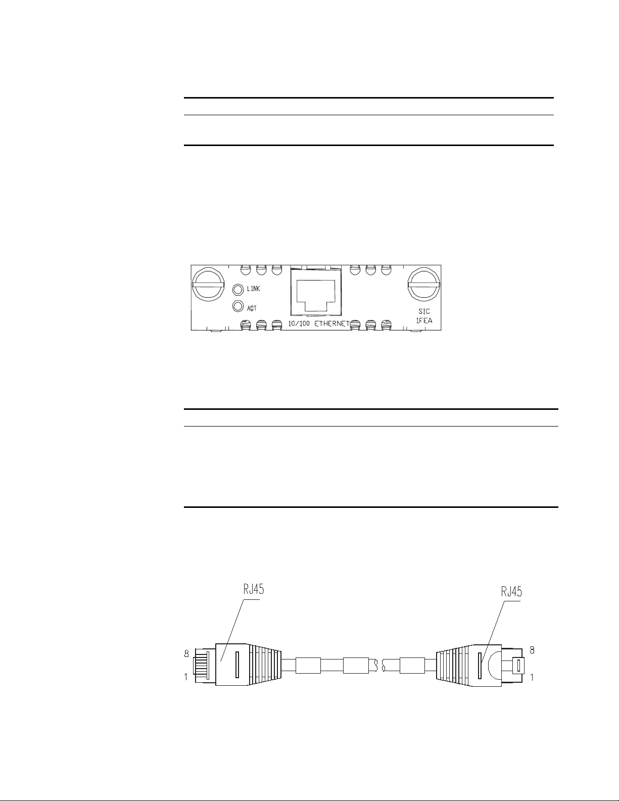
SIC-1FEA
Introduction 1-port 10Base-T/100Base-TX Ethernet interface card (SIC-1FEA), in which FE
n
Interface Attributes The interface attributes of SIC-1FEA are given in the following table:
For H3C MSR 20-40 and MSR 30 and 50 series routers which have four SIC slots, a
4FSW/1FEF/1FEA/1GEC/1ADSL/1ADSL-I interface card can only be installed in slot
2 or slot 4.
stands for Fast Ethernet and A is used to differentiate SIC-1FEA from the 1FE
module. SIC-1FEA is used to implement the communication between Routers and
LANs. It supports:
■ Effective transmission distance of 100 meters with category-5 twisted pair
cables;
■ Operating speeds of both 100 Mbps and 10 Mbps and autosensing;
■ Both full duplex (in common use) and half-duplex operating modes.
For H3C MSR 20-40 and MSR 30/50 series routers, a SIC-1FEA interface card can
only be installed in SLOT2 or SLOT4.
Tab l e 1 Interface attributes of SIC-1FEA
Attribute SIC-1FEA
Connector type RJ-45
Interface type MDI
Number of connectors 1
Cable type Straight-through Ethernet cable
Page 22
22 CHAPTER 2: SMART INTERFACE CARDS
Tab le 1 Interface attributes of SIC-1FEA
Attribute SIC-1FEA
Operating mode 10/100 Mbps autosensing
Full duplex/half duplex
n
interfaces on the network cards belong to this type. MDIX stands for Cross Media
Dependent Interface, which is usually adopted on HUBs or LAN Switches.
Interface LEDs SIC-1FEA panel is shown in the following figure:
MDI stands for Media Dependent Interface of the Ethernet. Normally, the
Figure 5 SIC-1FEA panel
The status description of the LEDs on SIC-1FEA panel is listed in the following
table:
Tab le 2 Description of the LEDs on SIC-1FEA panel
LED Description
LINK OFF means no link is present;
ACT OFF means no data is being
ON means a link is present.
transmitted or received;
Blinking means data is being received
or/and transmitted.
Interface Cable Normally, category-5 twisted pair cable is adopted to connect the 10BASE-T
/100BASE-TX Ethernet interface to the Ethernet, as shown in the following figure:
Figure 6 Ethernet cable
Ethernet cables fall into two categories: straight-through cables and crossover
cables, specifically,
Page 23

SIC-1SAE 23
■ Straight-through cable: the wire sequences of the twisted pair cable crimped in
the RJ-45 connectors at both ends are completely the same. It is used to
connect terminal devices (such as PCs, routers) to Hubs or LAN Switches.
■ Crossover cable: The wire sequences of twisted pair cable crimped in the RJ-45
connectors at both ends are different. It can be used to connect two terminal
devices (such as PCs and Routers). You can such kind of cables by yourself if
necessary.
For the pinouts, identification and making methods of these two kinds of network
cables, see Low-End and Mid-Range Series Routers Cable Manual.
Connecting the Interface
Cable
If the SIC has been properly installed, follow these steps to connect the interface
cable:
Step 1: Connect the Ethernet port of SIC to a PC or router using a crossover cable
and to a Hub or LAN Switch using a straight-through cable;
Step 2: Check the status of LINK LED on the SIC-1FEA panel: ON means the link is
connected and OFF means the link is not connected. In the latter case, check the
line.
SIC-1SAE
Introduction SIC-1SAE, 1-port enhanced high-speed synchronous/asynchronous serial interface
card, provides functions similar to SA, but its serial interfaces support more
protocols, such as RS449, X.21, and RS530.
Interface Attributes The interface attributes of the SIC-1SAE are given in the following table:
Tab l e 3 Interface attributes of the SIC-1SAE
Description
Attribute
Connector DB-28
Number of connectors 1
Interface standard and
operating mode
Synchronous Asynchronous
V.24 V.35, RS449,
X.21, RS530
DTE, DCE DTE, DCE
RS232
Minimum baud rate
(bps)
Maximum baud rate
(bps)
1200 1200 300
64 k 2.048 M 115.2
Page 24
24 CHAPTER 2: SMART INTERFACE CARDS
Tab le 3 Interface attributes of the SIC-1SAE
Attribute
Cable V.24 (RS232) DTE cable
Supported service 1) DDN leased line
Description
Synchronous Asynchronous
V.24 (RS232) DCE cable
V.35 DTE cable
V.35 DCE cable
X.21 DTE cable
X.21 DCE cable
RS449 DTE cable
RS449 DCE cable
RS530 DTE cable
RS530 DCE cable
1) Dialup through modems
2) Terminal access service
2) Backup
3) Asynchronous leased line
4) Terminal access
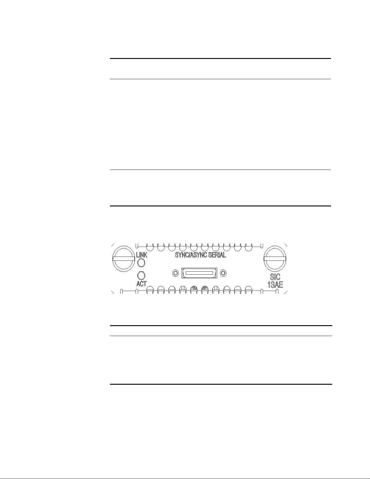
Interface LEDs SIC-1SAE panel is shown in the following figure:
Figure 7 SIC-1SAE panel
Description of the LEDs on SIC-1SAE panel is given in the following table:
Tab le 4 LEDs on SIC-1SAE panel
LED Description
LINK OFF means no link is present;
ACT OFF means no data is being
ON means a link is present.
transmitted or received;
Blinking means data is being received
or/and transmitted.
Interface Cable The SIC-1SAE uses a synchronous/asynchronous serial interface cable with DB-28
connectors for connection.
Before connecting to a port on the SIC-1SAE, confirm the line properties of the
interface to select an appropriate cable from the following cable options:
■ V.24 (RS232) DTE cable: DB-25 (male) connector at the network end
Page 25
SIC-1SAE 25
■ V.24 (RS232) DCE cable: DB-25 (female) connector at the network end
■ V.35 DTE cable: 34PIN (male) connector at the network end
■ V.35 DCE cable: 34PIN (female) connector at the network end
■ X.21 DTE cable: DB-15 (male) connector at the network end
■ X.21 DCE cable: DB-15 (female) connector at the network end
■ RS449 DTE cable: DB-37 (male) connector at the network end
■ RS449 DCE cable: DB-37 (female) connector at the network end
■ RS530 DTE cable: DB-25 (male) connector at the network end
■ RS530 DCE cable: DB-25 (female) connector at the network end
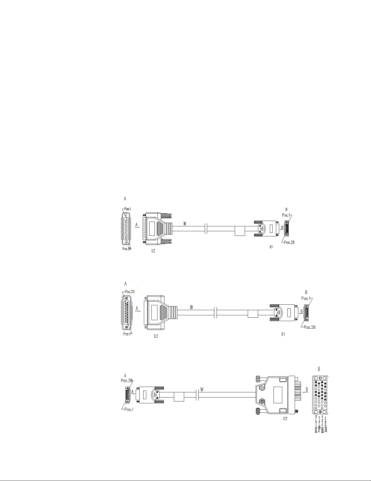
At one end of these cables is a DB-28 connector and at the other end is the
connector that varies with the port at the network side.
■ V.24 DTE cable
Figure 8 V24 DTE cable
■ V.24 DCE cable
Figure 9 V.24 DCE cable
■ V.35 DTE cable
Figure 10 V.35 DTE cable
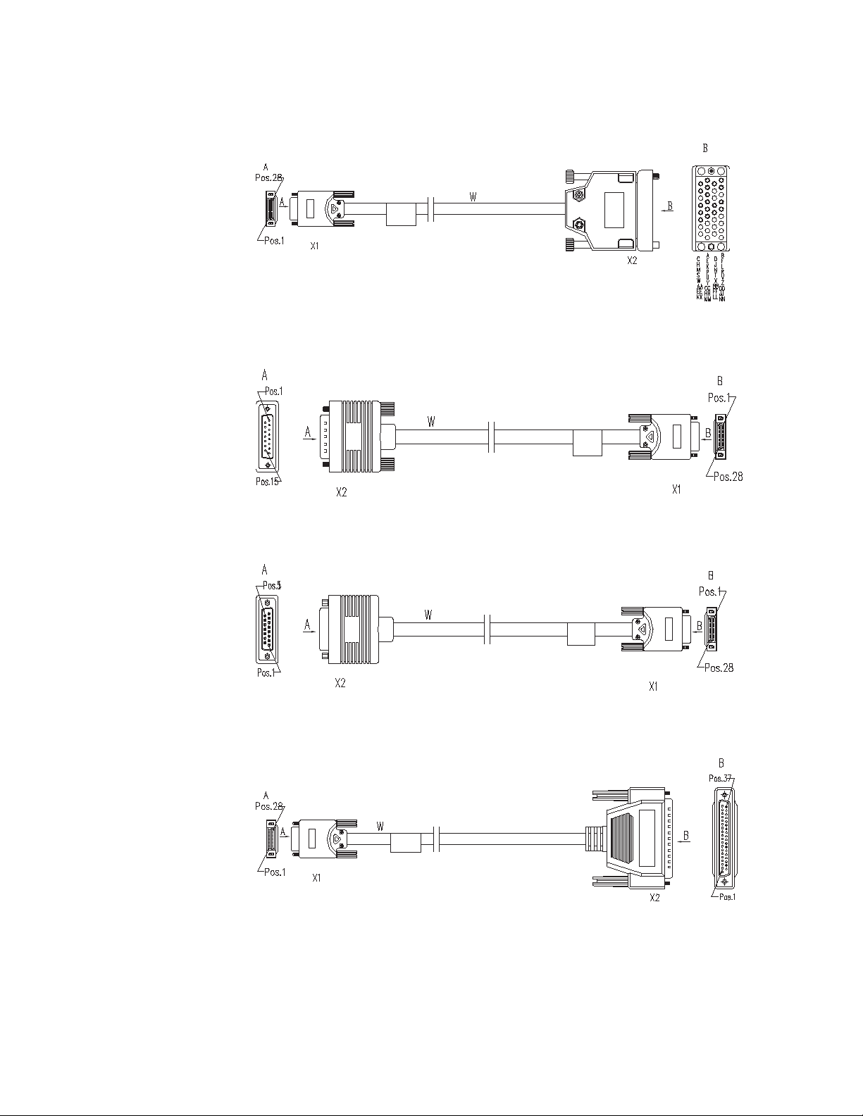
■ V.35 DCE cable
Page 26
26 CHAPTER 2: SMART INTERFACE CARDS
Figure 11 V.35 DCE cable
■ X.21 DTE cable
Figure 12 X.21 DTE cable
■ X.21 DCE cable
Figure 13 X.21 DCE cable
■ RS449 DTE cable
Figure 14 RS449 DTE cable
■ RS449 DCE cable
Page 27
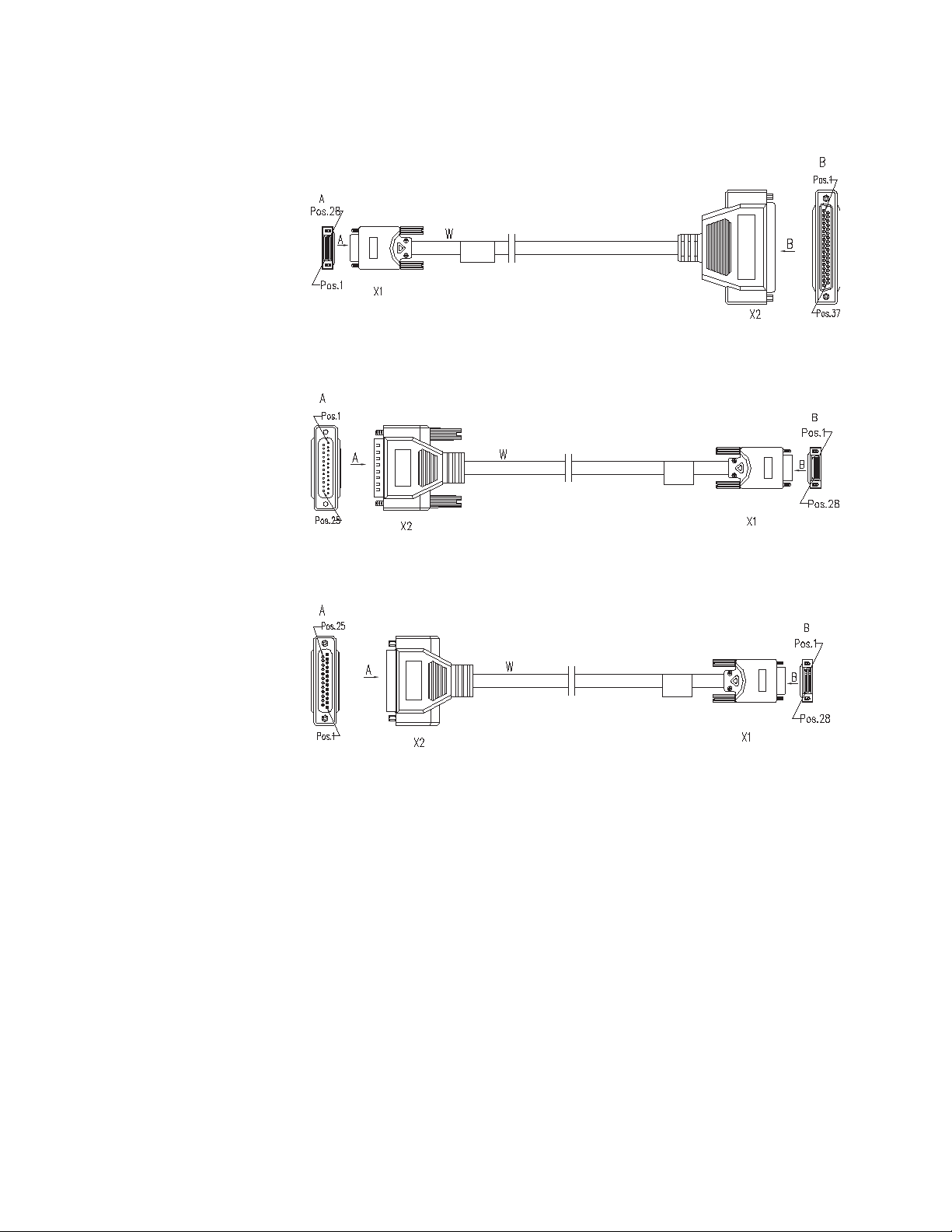
Figure 15 RS449 DCE cable
■ RS530 DTE cable
Figure 16 RS530 DTE cable
SIC-1SAE 27
n
Connecting the Interface
Cable
w
■ RS530 DCE cable
Figure 17 RS530 DCE cable
For the pinouts of synchronous/asynchronous serial cables (with DB-28
connectors), see Low-End and Mid-Range Series Routers Cable Manual.
These cables are optional items. Please select one when purchasing a SIC-1SAE
card; by default, the cable is not provided.
WARNING:
■ Before plugging or unplugging the interface cable connected to the SIC-1SAE
card, power off the router. Online insertion or removal tends to damage the
port and even the device.
■ Before connecting the SIC-1SAE card to a remote device, identify the type of
the device, such as its synchronous/asynchronous mode and DTE/DCE mode,
and the signaling criterion, baud rate and time clock required by the access
device.
Page 28

28 CHAPTER 2: SMART INTERFACE CARDS
SIC-1EPRI/SIC-1E1-F
Introduction 1-port channelized E1/CE1/PRI compatible interface card (SIC-1EPRI) supports:
Step 1: Choose a synchronous/asynchronous serial interface cable depending on
the type of the interface on the remote device.
Step 2: Plug the DB-28 connector of the cable to the DB-28 port on the SIC-1SAE.
Step 3: Connect the other end of the SAE cable to:
■ Port of CSU/DSU if the WAN is a DDN line.
■ Serial port on an analog modem if the WAN is a dial-up line.
Step 4: Check the behavior of the LINK LED on the card panel. It is OFF when the
line is faulty and signal is out of synchronization. Check the line for the cause.
■ Transmission/Receiving and handling of E1 data streams;
■ CE1 (channelized E1) access;
■ ISDN PRI function;
■ Remote loopback and local loopback functions, facilitating fault test and
location.
It is possible to use the card for multiple purposes through different
configurations.
Following are the differences between SIC-1EPRI and 1-port Fractional E1 interface
card (SIC-1E1-F):
■ FE1 mode of SIC-1E1-F can support only one channel bundle (the rate is n ×
64kbps, n=1-31), while the 31 channels can be grouped into multiple arbitrary
bundles by SIC-1EPRI;
■ SIC-1E1-F does not support PRI mode.
Interface Attributes The interface attributes of SIC-1EPRI/SIC-1E1-F are given in the following table:
Tab le 5 Interface attributes of SIC-1EPRI/SIC-1E1-F
Attribute Description
Connector type DB-15
Number of connectors 1
Interface standard G.703, G.704
Interface rate 2.048 Mbps
Cable type 75-ohm non-balanced coaxial cable
(DB-15 to BNC)
120-ohm balanced twisted-pair cable
(DB-15 to RJ-45)
Coaxial connector, network interface
connector and 75-ohm to 120-ohm
adapter
Page 29
SIC-1EPRI/SIC-1E1-F 29
Tab l e 5 Interface attributes of SIC-1EPRI/SIC-1E1-F
Attribute Description
Operating mode E1
CE1, ISDN PRI (supported by SIC-1EPRI
only)
FE1(supported by SIC-1E1-F only)
Supported service Backup
Terminal access
ISDN (supported by SIC-1EPRI only)
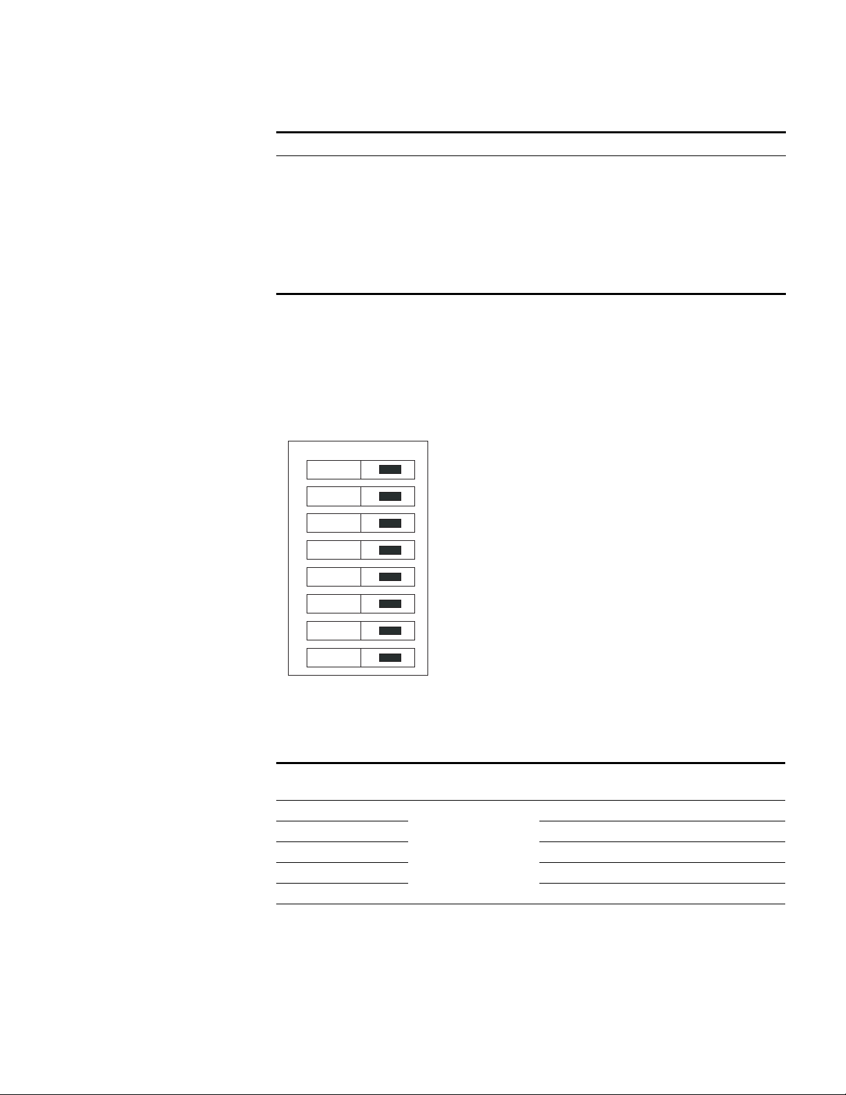
DIP Switch E1/CE1/PRI interface is compatible with both 75-ohm impedance and 120-ohm
impedance. The interface matches different types of impedance through an 8BIT
DIP switch. By default, all the 8 positions of the DIP switch are ON, as shown in the
following figure:
Figure 18 Default setting of the DIP switches
on
1
2
3
4
5
6
7
8
8BIT description and settings of DIP switch are given in the following table:
Tab l e 6 Description and settings of the internal DIP switch of SIC-ERRI/SIC-1E1-F
120-ohm
DIP switch Description 75-ohm impedance
1BIT Switch for
2BIT ON OFF
3BIT ON OFF
4BIT ON OFF
5BIT ON OFF
6BIT Switch for RxRing
75-ohm/120-ohm
options
grounding mode
options
ON OFF
OFF: RxRing grounding
via capacitor
ON: RxRing directly
grounding
impedance
-
Page 30

30 CHAPTER 2: SMART INTERFACE CARDS
Tab le 6 Description and settings of the internal DIP switch of SIC-ERRI/SIC-1E1-F
DIP switch Description 75-ohm impedance
7BIT Switch for RxShield
8BIT Switch for RxShield
grounding options
grounding options
120-ohm
impedance
- ON: RxShield
grounding
OFF: RxShield
ungrounding
- OFF: RxShield
grounding via
capacitor
ON: RxShield
directly grounding
c
CAUTION:
■ When setting internal DIP switch, you are recommended to: turn ON all BITs
from 1 to 8 when a 75-ohm cable is connected. Turn OFF all BITs from 1 to 8
when a 120-ohm cable is connected;
■ The default configuration of internal DIP switch is that all the 8 positions of the
BIT switch are ON, that is, the E1 interface impedance is 75-ohm.
Interface LEDs SIC-1EPRI panel is shown in the following figure:
Figure 19 SIC-1EPRI panel
SIC-1E1-F panel is shown in the following figure:
Figure 20 SIC-1E1-F panel
Fractional E1
The status description of the LEDs is given in the following table:
Tab le 7 Description of the LEDs on SIC-1EPRI/SIC-1E1-F panel
LED Description
LINK ON means carrier signal has been received.
OFF means no carrier signal has been
received.
ACT OFF means no data is being transmitted or
received; blinking means data is being
received or/and transmitted.
Page 31

SIC-1EPRI/SIC-1E1-F 31
Interface Cable Interface cables for SIC-1EPRI/SIC-1E1-F are standard E1 G.703 cables. E1 G.703
cables have two types: 75-ohm non-balanced coaxial cables and 120-ohm
balanced twisted pair cables, shown as follows:
■ 75-ohm non-balanced coaxial cable
Figure 21 E1 G.703 75-ohm non-balanced coaxial cable
75-ohm non-balanced coaxial cable connects SIC-1EPRI/SIC-1E1-F with the DB-15
connector and the network end with the BNC connector.
n
n
A pair of coaxial connectors is available for extending the E1 cable. Both ends of
the connectors are BNC receptacles that can be used to connect two 75-ohm
non-balanced coaxial cables with BNC connectors.
■ 120-ohm balanced twisted pair cable
Figure 22 E1 G.703 120-ohm balanced twisted pair cable
120-ohm balanced twisted pair cable connects SIC-1EPRI/SIC-1E1-F with the
DB-15 connector and network end with the RJ-45 connector.
A network interface connector is available for extending the E1 cable. Both ends
of the connector are RJ-45 jacks that can be used to connect two 120-ohm
balanced twisted pair cables.
In addition, a 75-ohm to 120-ohm adapter is available.
For the pinouts of E1 cables, see Low-End and Mid-Range Series Routers Cable
Manual.
c
Connecting the Interface
Cable
c
CAUTION: E1 cable, coaxial connector, network interface connector and
75ohm-to-120ohm adapter are optional. Please order them together with
SIC-1EPRI/SIC-1E1-F. By default, they are not supplied.
CAUTION: When using E1 cable outdoors, you are recommended to install a
special lightning arrester on the input end of the cable in order to avoid lightning
more effectively.
Page 32

32 CHAPTER 2: SMART INTERFACE CARDS
If the SIC has been properly installed, follow these steps to connect the cable:
Step 1: Check the type of E1 cable and correctly set the DIP switch (the ex-factory
setting of E1/CE1/PRI interface impedance is 75-ohm);
Step 2: Connect the DB-15 connector of E1 cable to SIC-1EPRI/SIC-1E1-F;
Step 3: Connect the other end of the E1 cable to the corresponding network
device:
1 When the E1 cable is a 75-ohm unbalanced coaxial cable:
■ Directly connect the BNC connector of the cable to the remote equipment if
there is no need for extension, or
■ Connect the BNC connector of the cable to the coaxial connector and the
other end of the coaxial connector to the remote network equipment through
a 75-ohm E1 trunk cable, if cable extension is needed.
c
wire marked RX and the wire marked RX should be connected to the peer wire
marked TX.
CAUTION: The wire marked TX in the E1 cable should be connected to the peer
Figure 23 Extending an E1 75-ohm non-balanced coaxial cable
DB-15
BNC
Router
Coaxial connector
75-ohm non-balanced coaxial cable
BNC
75-ohm E1 trunk cable
If the remote device has 120-ohm interface, it is needed to use a
75-ohm-to-120-ohm adapter or use a 120-ohm cable.
2 When the E1 cable is a 120-ohm balanced twisted pair cable:
■ Directly connect the RJ-45 connector of the cable to the RJ-45 port of the
remote equipment, if there is no need to extend the E1 cable, or
■ Connect the RJ-45 connector of the cable to the network connector and the
other end of the network connector to the network equipment through a
120-ohm E1 trunk cable, if cable extension is needed.
Network
devices
such as DDN
Page 33

SIC-1TPRI/SIC-1T1-F 33
Figure 24 Extending an E1 120-ohm balanced twisted pair cable
DB-15
SIC-1TPRI/SIC-1T1-F
Introduction 1-port channelized T1/CT1/PRI compatible interface card (SIC-1TPRI) supports:
Network
devices such
as DDN
Router
Network interface connector
120-ohm balanced twisted pair
RJ-45
RJ-45
120-ohm E1 trunk cable
Step 4: Check the status of LINK LED on the SIC-1EPRI/SIC-1E1-F panel: ON means
the link is connected and OFF means the link is not connected. In the latter case,
check the line.
■ Transmission/Receiving and handling of T1 data streams;
■ CT1 (channel T1) access;
■ ISDN PRI function;
■ Remote loopback and local loopback, facilitating the effective and flexible
debugging.
It is possible to use the card for multiple purposes through different
configurations.
Following are the differences between SIC-1TPRI and 1-port Fractional T1 interface
card (SIC-1T1-F):
■ FT1 mode of SIC-1T1-F can support only one channel bundle (the rate is n × 56
kbps, n=1-24), while the 24 channels can be grouped into multiple arbitrary
bundles by SIC-1TPRI.
■ SIC-1T1-F does not support PRI mode.
Interface Attributes The interface attributes of SIC-1TPRI/SIC-1T1-F are given in the following table:
Tab l e 8 Interface attributes of SIC-1TPRI/SIC-1T1-F
Attribute Description
Connector type RJ-45
Number of connectors 1
Page 34

34 CHAPTER 2: SMART INTERFACE CARDS
Tab le 8 Interface attributes of SIC-1TPRI/SIC-1T1-F
Attribute Description
Interface standard G.703/T1.102
Interface rate 1.544 Mbps
Cable type T1 cable (100-ohm standard shielded
Operating mode CT1, ISDN PRI (supported by SIC-1TPRI
Supported service Backup
G.704
AT&T TR 54016
AT&T TR 62411
ANSI T1.403
network cable)
only)
FT1(supported by SIC-1T1-F only)
Terminal access
ISDN (supported by SIC-1TPRI only)
Interface LEDs SIC-1TPRI panel is shown in the following figure:
Figure 25 SIC-1TPRI panel
SIC-1T1-F panel is shown in the following figure:
Figure 26 SIC-1T1-F panel
The status description of the LEDs is given in the following table:
Page 35

SIC-1TPRI/SIC-1T1-F 35
Tab l e 9 Description of the LEDs on SIC-1TPRI/SIC-1T1-F panel
LED Description
LINK/ACT ON means the carrier signal has been
received.
OFF means no carrier signal has been
received.
Blinking means data is being transmitted
or/and received.
LP/AL ON means the interface is in a loopback.
Blinking means an AIS, LFA, or RAI alarm
signal is present.
OFF means no loopback or alarm is
present.
Note:
AIS = Alarm indication signal; LFA = loss of frame alignment; RAI = Remote alarm indication
Interface Cable SIC-1TPRI/SIC-1T1-F interface cable is 100-ohm standard shielded network cable
that has RJ-45 connectors at both ends. The following figure illustrates a
SIC-1TPRI/SIC-1T1-F interface cable:
c
Connecting the Interface
Cable
c
Figure 27 T1 cable
For the pinouts of T1 cable, see Low-End and Mid-Range Series Routers Cable
Manual.
CAUTION: Relevant cables are included in the standard shipment package of
SIC-1TPRI/SIC-1T1-F. Please order them together with SIC-1TPRI/SIC-1T1-F. By
default, they are not supplied.
CAUTION:
■ You should connect a cable to the port with the correct mark. Improper
plugging is prone to impair the SIC/MIM and even damage the router.
■ When using T1 cable outdoors, you are recommended to install a special
lightning arrester on the input end of the cable so as to avoid lightning more
effectively.
If the SIC has been properly installed, follow these steps to connect the cable:
Step 1: Connect one end of the T1 cable to the RJ-45 port of SIC-1TPRI/SIC-1T1-F;
Page 36

36 CHAPTER 2: SMART INTERFACE CARDS
SIC-1AM/SIC-2AM
Introduction 1/2-port analog modem interface card (SIC-1AM/SIC-2AM) integrates the
Step 2: Connect the other end of the T1 cable to the relevant equipment;
Step 3: Check the status of LINK LED on the SIC-1TPRI/SIC-1T1-F panel: ON means
the link is connected and OFF means the link is not connected. In the latter case,
check the line.
functions of asynchronous interface and external modem, that is, allowing 1/2
channel(s) of remote modem subscribers to directly access the Router. They
support:
■ Data rate of 56 kbps.
■ Accessing and handling analog signals and transmitting the processed data to
the Router host through the serial interface bus. And also, processing the data
received from the host and then transmitting them to the PSTN via the
telephone port.
Interface Attributes The interface attributes of SIC-1AM/SIC-2AM are given in the following table:
Table 10 Interface attributes of SIC-1AM/SIC-2AM
Attribute Description
Connector type RJ11
Number of connectors 1 (SIC-1AM)
2 (SIC-2AM)
Cable type Telephone cable with ferrite core
Maximum speed 56 kbps
Interface LEDs
Supported standard ITU-T V.90, V.34 (33.6 kbps), V.FC,
Supported service Modem dial-up
Figure 28 SIC-1AM panel
V.32 bis, V.32, V.22 bis, V.22A/B,
V.23, V.21, Bell 212A a, Bell 103.
Figure 29 SIC-2AM panel
Page 37

SIC-1FXS/SIC-1FXO & SIC-2FXS/SIC-2FXO 37
Table 11 Description of the LEDs on SIC-1AM/SIC-2AM panel
LED Description
LINK OFF means the link is idle. ON means the
connection has been established. Blinking
means the connection is being set up.
ACT OFF means the link is idle. Blinking means
Interface Cable The connection cables for SIC-1AM/SIC-2AM are telephone cables with ferrite
core. Both ends of the cables are RJ11 connectors. For cable pinouts, refer to
Low-End and Mid-Range Series Routers Cable Manual.
data is being transmitted or received.
c
Connecting the Interface
Cable
c
SIC-1FXS/SIC-1FXO & SIC-2FXS/SIC-2FXO
Introduction 1/2-port voice subscriber circuit interface card (SIC-1FXS/SIC-2FXS) and 1/2-port
CAUTION: Relevant cables are included in the standard shipment package of
SIC-1AM/SIC-2AM.
CAUTION:
■ You should connect a cable to the port with the correct mark. Misplugging is
prone to impair the SIC/MIM and even damage the router.
■ You are recommended to install a special lightning arrester on the input end of
the telephone line in order to avoid the lightning effects more efficiently.
If the SIC has been properly installed, follow these steps to connect the cable:
Step 1: Insert the end with ferrite core into one LINE port of SIC-1AM/SIC-2AM;
Step 2: Plug the other end of the cable into the telephone wall jack;
voice AT0 analog trunk interface card (SIC-1FXO/SIC-2FXO) serve to access and
handle 1/2 channel(s) of analog voice signals over data communication networks.
The differences between SIC-FXS and SIC-FXO are listed below:
■ SIC-FXS cards are analog subscriber line cards that provide ordinary analog
telephone and fax access and also can connect AT0 loop trunks of exchanges;
■ SIC-FXO cards are loop trunk cards that provide access of common subscriber
lines of exchanges.
c
Interface Attributes The interface attributes of SIC-1FXS/SIC-1FXO and SIC-2FXS/SIC-2FXO are given in
CAUTION: While using SIC-FXS/SIC-FXO, you must ensure that the H3C Routers
can be connected to IP networks or other WANs.
the following table:
Page 38

38 CHAPTER 2: SMART INTERFACE CARDS
Table 12 Interface attributes of SIC-1FXS/SIC-1FXO and SIC-2FXS/SIC-2FXO
Attribute Description
Connector type RJ11
Number of connectors 1 (SIC-1FXS/SIC-1FXO)
Interface standard Subscriber circuit interface
Cable type Telephone cable with ferrite core.
Dialing mode Supports DTMF, not supports pulse
Bandwidth 300 Hz to 3400 Hz
2 (SIC-2FXS/SIC-2FXO)
(SIC-1FXS/SIC-2FXS) compliant with
ITU Q.512.
Loop trunk interface
(SIC-1FXO/SIC-2FXO) compliant with
ITU Q.552.
Over-current and over-voltage
protection compliant with ITU K.20
dial-up.
Interface LEDs ■ SIC-1FXS/SIC-1FXO panel
Figure 30 SIC-1FXS panel
Figure 31 SIC-1FXO panel
■ SIC-2FXS/SIC-2FXO panel
Figure 32 SIC-2FXS panel
Figure 33 SIC-2FXO panel
Page 39

SIC-4FSW/SIC-4FSW-PoE/DSIC-9FSW/DSIC-9FSW-PoE 39
The status description of the LEDs of SIC-1FXS/SIC-1FXO and SIC-2FXS/SIC-2FXO is
shown in the following table:
Table 13 Description of the LEDs on SIC-1FXS/SIC-1FXO and SIC-2FXS/SIC-2FXO panels
LED Description
LINK OFF means the link is idle. ON means the
link is being occupied for call connection.
ACT OFF means the link is idle. ON means the
link is being occupied for communication.
Interface Cable Connection cables for SIC-1FXS/SIC-1FXO and SIC-2FXS/SIC-2FXO are telephone
cables with ferrite core. Both ends of the cables are RJ11 connectors. For cable
pinouts, see Low-End and Mid-Range Series Routers Cable Manual.
c
Connecting the Interface
Cable
c
CAUTION: The standard shipment package of SIC-1FXS/SIC-1FXO and
SIC-2FXS/SIC-2FXO includes a ferrite core telephone cable.
CAUTION:
■ You should connect a cable to the port with the correct mark. Misplugging is
prone to impair the SIC/MIM and even damage the router.
■ When the telephone cable is used outdoors, it is recommended that users
install a special lightning arrester on the input end of the cable in order to
avoid the lightning effects more efficiently.
■ One end of the telephone cable has a ferrite core. To ensure the compatibility
of the Router, users should connect the end with the ferrite core to the Router.
If the SIC is properly installed, follow these steps to connect the cable:
Step 1: Connect the end with the ferrite core to a RJ11 port of SIC-FXS/SIC-FXO;
Step 2: Insert the other end to
■ a telephone or fax or the AT0 loop trunk if a SIC-1FXS/SIC-2FXS is installed;
SIC-4FSW/SIC-4FSW-Po E/DSIC-9FSW/DSIC-9FS W-PoE
Introduction SIC-4FSW/SIC-4FSW-PoE and DSIC-9FSW/DSIC-9FSW-PoE interface cards are
■ a subscriber line of exchange if a SIC-1FXO/SIC-2FXO is installed;
4/9-port 10/100 Mbps Ethernet Layer 2 SIC interface cards that can be used on
H3C MSR 20/30/50 series routers. They provide up to 4/9 10/100 Base-Tx Ethernet
ports for Layer 2 and Layer 3 switching. A router installed with
SIC-4FSW/DSIC-9FSW modules can work as a switching/routing integrated device
on a small-sized enterprise network to connect PCs and network devices inside the
Page 40

40 CHAPTER 2: SMART INTERFACE CARDS
network directly. SIC-4FSW-PoE/DSIC-9FSW-PoE interface cards can supply power
to powered devices (PDs) through power over Ethernet (PoE).
Functions supported by interface cards are as follows.
■ Effective transmission distance of 100 meters with category-5 twisted pair
cables (both crossover and straight-through);
■ Effective transmission distance of 100 meters between any interfaces with
category-5 twisted pair cables (both crossover and straight-through);
■ Operating speeds of both 100 Mbps and 10 Mbps and autosensing;
■ Both full duplex (in common use) and half-duplex operating modes.
Interface Attributes
Table 14 Interface attributes of the SIC-4FSW/SIC-4FSW-PoE/DSIC-9FSW/DSIC-9FSW-PoE
Description
SIC-4FSW/SIC-4FSW-PoE
Attribute
Connector RJ-45
Interface type MDI/MDIX
Number of
connectors
Cable Standard (straight-through)/cross-over Ethernet cable
Operation mode 10/100 Mbps autosensing, full/half duplex
interface card
Four 100 Mbps RJ45 connectors Nine 100 Mbps RJ45 connectors
DSIC-9FSW/DSIC-9FSW-PoE
interface card
MDI stands for Media Dependent Interface of the Ethernet. Normally, the
n
interfaces on the network cards belong to this type. MDIX stands for Cross Media
Dependent Interface, which is usually adopted on HUBs or LAN Switches.
Interface LEDs The following figure illustrates the SIC-4FSW/SIC-4FSW-PoE panel.
Figure 34 SIC-4FSW/SIC-4FSW-PoE panel
The following figure illustrates the DSIC-9FSW/DSIC-9FSW-PoE panel.
Figure 35 DSIC-9FSW/DSIC-9FSW-PoE panel
On the panel, each port corresponds with one green LED. The following table
describes the LEDs on the panel.
Page 41

SIC-4FSW/SIC-4FSW-PoE/DSIC-9FSW/DSIC-9FSW-PoE 41
Table 15 LEDs on the panel
LED Description
Steady ON A link is present, but there is no data being
transmitted or received.
OFF No link is present.
Blinking A link is present and there is data being
transmitted and received (ACT).
In addition, there is a POE LED on each board, which is provided for the
corresponding boards (SIC-4FSW-POE and DSIC-9FSW-POE) with the POE
function.
Interface Cable Normally, category-5 twisted pair cable is adopted to connect the 10BASE-T
/100BASE-TX Ethernet interface to the Ethernet, as shown in the following figure:
Figure 36 Ethernet cable
Connecting the Interface
Cable
c
Ethernet cables fall into two categories: straight-through cables and crossover
cables, specifically,
■ Straight-through cable: the wire sequences of the twisted pair cable crimped in
the RJ-45 connectors at both ends are completely the same. It is used to
connect terminal devices (such as PCs, routers) to Hubs or LAN Switches.
■ Crossover cable: The wire sequences of twisted pair cable crimped in the RJ-45
connectors at both ends are different. It can be used to connect two terminal
devices (such as PCs and Routers).
For the pinouts, identification and making methods of these two kinds of network
cables, see Low-End and Mid-Range Series Routers Cable Manual.
CAUTION: You should connect a cable to the port with the correct mark.
Misplugging is prone to impair the interface card and even damage the router.
If the SIC has been properly installed, follow these steps to connect the interface
cable:
Step 1: Connect the Ethernet port of SIC to a PC or router using a crossover cable
and to a Hub or LAN Switch using a straight-through cable;
Step 2: Check the status of LINK LED on the panel: ON means the link is connected
and OFF means the link is not connected. In the latter case, check the line.
Page 42

42 CHAPTER 2: SMART INTERFACE CARDS
SIC-1GEC
Introduction 1-port 10/100/1000 Mbps electrical and fiber Ethernet interface SIC card
(SIC-1GEC) has the following functions:
■ Receipt, transmission and processing of GE data stream;
■ CE electrical and fiber interface access;
■ 1000/100/10 Mbps on electrical interface;
■ 1000 Mbps on fiber interface
n
only be installed in SLOT2 or SLOT4.
Interface Attributes The attributes of SIC-1GEC interface are shown in the following table.
Table 16 Interface Attributes of the SIC-1GEC
Attribute Description
Connector RJ-45
Interface type MDI
Frame format Ethernet_II
Ethernet_SNAP
IEEE 802.2
IEEE 802.3
Operation mode 10/100/1000 Mbps autosensing
Full/half duplex
Network protocol IP
Novell IPX
Table 17 Attributes of SFP module
For H3C MSR 20-40 and MSR 30/50 series routers, a SIC-1GEC interface card can
SFP module
name Wavelength Connector
1000BASE-SX-SFP 850 nm LC 50/125 µm
1000BASE-LX-SFP 1310 nm 9/125 µm
1000BASE-LH-SF
P
1000BASE-ZX-LR
-SFP
1000BASE-ZX-V
R-SFP
1000BASE-ZX-U
R-SFP
1550 nm
Fiber
specification
multi-mode fiber
62.5/125 µm
multi-mode fiber
single-mode
fiber
Maximum
transmission
distance
550 m (1804.5 ft.)
275 m (902.2 ft.)
10 km (6.2 mi.)
40 km (24.9 mi.)
70 km (43.5 mi.)
100 km (62.1 mi.)
Page 43

SIC-1GEC 43
c
electrical interfaces at the same time. When the router is powered on, the
electrical interface takes effect by default. If you want to use a fiber interface, use
a command to configure it.
Interface LEDs The following figure illustrates the SIC-1GEC panel.
CAUTION: SIC-1GEC uses COMBO interface; therefore it cannot support fiber and
Figure 37 SIC-1GEC panel
The following table describes the electrical interface LEDs on the left of the
SIC-1GEC panel.
Table 18 LEDs for the electrical interface on the left of the SIC-1GEC panel
LED Description
LINK ON means carrier signal is received;
OFF means no carrier signal is
received;
Green: Data is being received and
transmitted at a speed of 1000 Mbps.
Yellow: Data is being received and
transmitted at a speed of 100/10
Mbps.
ACT OFF: No data is being received and
transmitted;
Blinking: Data is being received and
transmitted.
Table 19 LEDs for the fiber interface on the right of the SIC-1GEC panel
LED Description
LINK ON means carrier signal is received;
OFF means no carrier signal is
received;
Green: Data is being received and
transmitted at a speed of 1000 Mbps;
Yellow: Fault.
ACT OFF: No data is being received and
transmitted;
Blinking: Data is being received and
transmitted.
Interface Cable Normally, category-5 twisted pair cable is adopted to connect the 10BASE-T
/100BASE-TX Ethernet interface to the Ethernet, as shown in the following figure:
Page 44

44 CHAPTER 2: SMART INTERFACE CARDS
Figure 38 Ethernet cable
Ethernet cables fall into two categories: straight-through cables and crossover
cables, specifically,
■ Straight-through cable: the wire sequences of the twisted pair cable crimped in
the RJ-45 connectors at both ends are completely the same. It is used to
connect terminal devices (such as PCs, routers) to Hubs or LAN Switches.
■ Crossover cable: The wire sequences of twisted pair cable crimped in the RJ-45
connectors at both ends are different. It can be used to connect two terminal
devices (such as PCs and Routers).
For the pinouts, identification and making methods of these two kinds of network
cables, see Low-End and Mid-Range Series Routers Cable Manual.
Connecting the Interface
Cable
c
w
Connecting Ethernet fiber interface cable
CAUTION: When connecting optical fiber, note that
■ Do not bend optical fiber with undue stress. The bend radius should be no less
than 10 cm (3.9 in.);
■ Ensure that the Tx interface and Rx interface of the module are connected
correctly;
■ Keep the sectional surface of optical fiber clean and free from dust.
WARNING: Laser Danger! Do not observe the optical fiber connector connected
with laser; otherwise, laser may damage your eyes.
Step 1: Plug SFP module into the corresponding SFP module slot.
Step 2: Locate the Rx optical port and Tx optical port on the module. Plug one end
of optical fiber into the Rx port of the module, and the other end into the Tx port
of the peer device. Plug one end of another optical fiber into the Tx port of the
module, and the other end into the Rx port of the peer device;
Step 3: Check the status of LINK LED on the GBE panel: ON means the Rx link is
connected and OFF means the Rx link is not connected. In the latter case, check
the line.
Connecting Ethernet electrical interface cable
Step 1: (Use a crossover cable for the connection to a PC/router and
straight-through cable to a Hub/LAN Switch.) Plug one end of the cable to an
Ethernet port of the Router and another end to the desired peer device;
Page 45

SIC-1VE1
SIC-1VE1 45
Step 2: Check the status of LINK LED on the GEC panel: ON means the link is
connected and OFF means the link is not connected. In the latter case, check the
line.
Introduction 1-port E1 voice interface card (SIC-1VE1) can handle dense voice signals in VoIP
system. It provides a CE1/PRI/R2 port, allowing the access of 30 channels of voice
signals.
n
Interface Attributes
■ When purchasing a SIC-1VE1 interface card, users should purchase a VCPM
and configure a VPM based on voice traffic.
■ No VCPM is required, but only a VPM needs to be installed on the main board
when MSR 20-1x series routers need to be equipped with a SIC-1VE1 interface
card.
■ VCPM and VPM need to be installed on the main board when MSR 30 series
routers need to be equipped with a SIC-1VE1 interface card.
■ VCPM and VPM need to be installed on the MSCA card when MSR 50 series
routers need to be equipped with a SIC-1VE1 interface card.
Table 20 Interface Attributes of the SIC-1VE1
Attribute Description
Connector DB 15
Number of connector 1
Interface standard G.703, G.704
Interface rate 2.048 Mbps
Frame format Ethernet_II
Ethernet_SNAP
IEEE 802.2
IEEE 802.3
Cable type 75-ohm non-balanced coaxial cable
120-ohm balanced twisted pair cable
Coaxial connector, network interface
connector and 75-ohm to 120-ohm
adapter (with BNC connector)
Operation mode CE1
ISDN PRI (only supported by SIC-1VE1)
R2
Services Backup
Terminal access
ISDN (only supported by SIC-1VE1)
DIP Switches CE1/PRI/R2 interface is compatible with 75-ohm and 120-ohm impedance.
Matching of different impedance is implemented through an 8BIT DIP switch. By
default, all the DIP switches are set to ON, as illustrated in the following figure:
Page 46

46 CHAPTER 2: SMART INTERFACE CARDS
Figure 39 Default setting of DIP switches
1
2
3
4
5
6
7
8
Description of DIP switch settings is given in the following table:
Table 21 Description of DIP switch settings of SIC-ERRI/SIC-1E1-F
on
c
DIP Description
1BIT 75-ohm/120-ohm
2BIT ON OFF
3BIT ON OFF
4BIT ON OFF
5BIT ON OFF
6BIT RxRing grounding
7BIT RxShield grounding
8BIT SxShield grounding
selection switch
mode selection
switch
mode selection
switch
mode selection
switch
Configuration of
75-ohm impedance
ON OFF
OFF: RxRing is
grounded via
capacitance.
ON: RxRing is
grounded directly.
- ON: RxShield is
- OFF: RxShield is
Configuration of
120-ohm impedance
-
grounded.
OFF: RxShield is not
grounded.
grounded via
capacitance
ON: RxShield is
grounded directly.
CAUTION:
■ It is recommended to select the DIP switch in this way: when connecting
75-ohm cable, flip BIT1-8 to ON, and when connecting 120-ohm cable, flip
BIT1-8 to OFF.
■ By default, all of the DIP switches are factory-configured to ON, that is, the
impedance of E1 interface is 75-ohm.
Interface LEDs The following figure illustrates the SIC-1VE1 panel.
Page 47

SIC-1VE1 47
Figure 40 SIC-1VE1 panel
The following table describes the LEDs on the SIC-1VE1 panel.
Table 22 LEDs for the electrical interface on the left of SIC-1GEC panel
LED Description
LINK ON means carrier signal is received;
OFF means no carrier signal is received.
ACT OFF: No data is being received and
transmitted;
Blinking: Data is being received and
transmitted.
Interface Cable The interface cable of SIC-1VE1/SIC-1E1-F is a standard E1 G.703 which has two
types: 75-ohm non-balanced coaxial cable and 120-ohm balanced twisted pair
cable. The following figure illustrates these two types of cables.
■ 75-ohm non-balanced coaxial cable
Figure 41 E1 G.703 75-ohm non-balanced coaxial cable
75-ohm non-balanced coaxial cable connects SIC-1VE1 with the DB-15 connector
and the network end with the BNC connector.
A pair of coaxial connectors is available for extending the E1 cable. Both ends of
n
the connectors are BNC receptacles that can be used to connect two 75-ohm
non-balanced coaxial cables with BNC connectors.
■ 120-ohm balanced twisted pair cable
Figure 42 E1 G.703 120-ohm balanced twisted pair cable
120-ohm balanced twisted pair cable connects SIC-1VE1 with the DB-15
connector and network end with the RJ-45 connector.
Page 48

48 CHAPTER 2: SMART INTERFACE CARDS
n
c
Connecting the Interface
Cable
c
A network interface connector is available for extending the E1 cable. Both ends
of the connector are RJ-45 jacks that can be used to connect two 120-ohm
balanced twisted pair cables.
In addition, a 75-ohm to 120-ohm adapter is available.
For the pinouts of E1 cables, see Low-End and Mid-Range Series Routers Cable
Manual.
CAUTION: E1 cable, coaxial connector, network interface connector and
75ohm-to-120ohm adapter are optional. Please order them together with
SIC-1VE1. By default, they are not supplied.
CAUTION: When using E1 cable outdoors, you are recommended to install a
special lightning arrester on the input end of the cable in order to avoid lightning
more effectively.
If the SIC has been properly installed, follow these steps to connect the cable:
Step 1: Check the type of E1 cable and correctly set the DIP switch (the ex-factory
setting of the interface impedance is 75-ohm);
Step 2: Connect the DB-15 connector of E1 cable to SIC-1VE1;
Step 3: Connect the other end of the E1 cable to the corresponding network
device:
1 When the E1 cable is a 75-ohm unbalanced coaxial cable:
■ Directly connect the BNC connector of the cable to the remote equipment if
there is no need for extension, or
■ Connect the BNC connector of the cable to the coaxial connector and the
other end of the coaxial connector to the remote network equipment through
a 75-ohm E1 trunk cable, if cable extension is needed.
c
CAUTION: The wire marked TX in the E1 cable should be connected to the peer
wire marked RX and the wire marked RX should be connected to the peer wire
marked TX.
Figure 43 Extending an E1 75-ohm non-balanced coaxial cable
DB-15
BNC
Router
BNC
Network
devices
such as DDN
Coaxial connector
75-ohm non-balanced coaxial cable
75-ohm E1 trunk cable
Page 49

SIC-1VT1 49
If the remote device has 120-ohm interface, it is needed to use a
75-ohm-to-120-ohm adapter or use a 120-ohm cable.
2 When the E1 cable is a 120-ohm balanced twisted pair cable:
■ Directly connect the RJ-45 connector of the cable to the RJ-45 port of the
remote equipment, if there is no need to extend the E1 cable, or
■ Connect the RJ-45 connector of the cable to the network connector and the
other end of the network connector to the network equipment through a
120-ohm E1 trunk cable, if cable extension is needed.
Figure 44 Extending an E1 120-ohm balanced twisted pair cable
DB-15
SIC-1VT1
Network
devices such
as DDN
Router
Ne tw ork inte rfac e conn ecto r
120-ohm balanced twisted pair
RJ-45
RJ-45
120-ohm E1 trunk cable
Step 4: Check the status of LINK LED on the SIC-1VE1 panel: ON means the link is
connected and OFF means the link is not connected. In the latter case, check the
line.
Introduction 1-port T1 voice interface card (SIC-1VT1) can handle dense voice signals in VoIP
system. It provides a CT1/PRI/R2 port, allowing the access of 23 channels of voice
signals.
n
■ When purchasing a SIC-1VT1 interface card, users should purchase a VCPM
and configure a VPM based on voice traffic.
■ No VCPM is required, but only a VPM needs to be installed on the main board
when MSR 20-1x series routers need to be equipped with a SIC-1VT1 interface
card.
Interface Attributes
■ VCPM and VPM need to be installed on the main board when MSR 30 series
routers need to be equipped with a SIC-1VT1 interface card.
■ VCPM and VPM need to be installed on the MSCA card when MSR 50 series
routers need to be equipped with a SIC-1VT1 interface card.
Table 23 Interface Attributes of the SIC-1T1-F
Attribute Description
Connector RJ45
Number of connector 1
Page 50

50 CHAPTER 2: SMART INTERFACE CARDS
Table 23 Interface Attributes of the SIC-1T1-F
Attribute Description
Interface standard G.703/T1.102
Interface rate 1.544 Mbps
Cable type T1 cable (100-ohm standard shielded
Operation mode CT1
Services Backup
Interface LEDs The following figure illustrates the SIC-1VT1 panel.
G.704
AT&T TR 54016
AT&T TR 62411
ANSI T1.403
cable)
ISDN PRI
Terminal access
ISDN
Figure 45 SIC-1VT1 panel
The following table describes the LEDs on the SIC-1VT1 panel.
Table 24 Description on SIC-1VT1 LED
LED Description
LINK ON means carrier signal is received;
OFF means no carrier signal is
received.
ACT OFF: No data is being received and
transmitted;
Blinking: Data is being received and
transmitted.
Interface Cable The interface cable of SIC-1VT1 is a standard 100-ohm standard shielding cable.
The connectors on the two ends use RJ 45. The following figure illustrates this
type of cable.
Page 51

SIC-1ADSL 51
Figure 46 T1 cable
For the pinouts of T1 cables, see Low-End and Mid-Range Series Routers Cable
Manual.
c
Connecting the Interface
Cable
c
CAUTION: The corresponding cables are not included in the standard shipment
package of SIC-1VT1. Please order them together with SIC-1VT1. By default, they
are not supplied.
CAUTION:
■ You should connect a cable to the port with the correct mark. Misplugging is
prone to impair the card and even damage the router.
■ When using T1 cable outdoors, you are recommended to install a special
lightning arrester on the input end of the cable in order to avoid lightning more
effectively.
If the SIC has been properly installed, follow these steps to connect the cable:
Step 1: Plug one end of T1 cable into the RJ45 connector of SIC-1VT1.
Step 2: Connect the other end of T1 cable to the peer device;
Step 3: Check the status of LINK LED on the SIC-1VT1 panel: OFF means the link is
not connected. In the latter case, check the line.
SIC-1ADSL
Introduction SIC-1ADSL, the 1-port ADSL over PSTN interface card, provides an RJ-11 interface
that can work as a WAN interface. It allows a LAN subscriber to connect to the
digital subscriber’s loop access multiplexer (DSLAM) at the central office over a
regular analog subscriber line or telephone line. Thus, the subscriber can access
the ATM/IP backbone or the Internet to enjoy services such as high-speed data
communication and video on demand (VoD).
ADSL transmits data in the high frequency band above 26 kHz. Therefore, it can
provide services without interfering with the voice service being provided in the
low frequency band (0 to 4 kHz) on the same line. It provides downlink rates in the
range 32 kbps to 8 Mbps and uplink rates in the range 32 kbps to 1 Mbps.
The SIC-1ADSL delivers these features:
Page 52

52 CHAPTER 2: SMART INTERFACE CARDS
■ Manual ADSL line activation and deactivation, providing a convenient fault
location means.
■ Interface standards of G. DMT, G. Lite, and T1.413, auto-sensing.
■ Trellis coding (except for G. Lite) on ADSL interfaces, enhancing the stability of
ADSL connection.
n
Interface Attributes
For H3C MSR 20-40 and MSR 30/50 series routers, a SIC-1ADSL interface card can
only be installed in SLOT2 or SLOT4.
Table 25 Interface attributes of the SIC-1ADSL
Attribute SIC-1ADSL
Connector RJ-11
Number of connectors 1
Interface rate
Interface standard ITU-T 992.1 G.DMT
Cable Telephone cable
Supported service ADSL over the regular telephone line
■ In ADSL full rate mode (ITU-T 992.1
G.DMT/ANSI T1.413):
8 Mbps (downlink rate)
1024 kbps (uplink rate)
■ In ADSL Lite mode (ITU-T 992.2
G.Lite):
64 kbps to 1 Mbps (downlink rate)
64 kbps to 512 kbps (uplink rate)
■ In ADSL2+ full rate mode (ITU-T
992.5):
24 Mbps (downlink rate)
1024 kbps (uplink rate)
ITU-T 992.2 G.Lite
ANSI T1.413 Issue 2
ITU-T 992.3
ITU-T 992.5
Interface LEDs The following figure illustrates the SIC-1ADSL panel.
Figure 47 SIC-1ADSL panel
The following table describes the LEDs on the card panel.
Page 53

SIC-1ADSL-I 53
Table 26 LEDs on the SIC-1ADSL panel
LED Description
LINK OFF means the loop is inactive.
ON means the loop has been activated and
has entered the data mode
Blinking means the loop is being activated.
ACT OFF means no data is being transmitted or
received; blinking means data is being
received or/and transmitted.
Interface Cable The interface cables that the SIC-1ADSL uses are regular telephone cables.
n
Connecting the Interface
Cable
The standard equipping package of the SIC-1ADSL includes the regular telephone
cable(s). You can separately order an external splitter as needed.
In G. Lite mode, no splitter is needed. You can directly connect the router to the
PSTN using a telephone cable, and simply connect the phone-set in parallel with
the router at the cable distribution box.
In full rate mode, a splitter is required. Follow these steps to connect the cables:
Step 1: Plug one end of a telephone cable into the ADSL port on the router, and
the other end into the internal ADSL port on the splitter.
Step 2: Connect the telephone to the phone port on the splitter with another
telephone cable.
Step 3: Connect the external ADSL port on the splitter to the PSTN with a third
telephone cable.
Figure 48 Connecting the SIC-1ADSL
Router
Router
Router
Router
DSL AM
DSL AM
DSL AM
RJ11 interf ace
RJ11 interf ace
RJ11 interf ace
RJ11 interf ace
RJ11 interf ace
RJ11 interf ace
RJ11 interf ace
RJ11 interf ace
Phone port
Phone port
DSL AM
SIC-1ADSL-I
POS
ADSL card
ADSL card
ADSL card
ADSL card
ADSL card
ADSL card
ADSL card
ADSL card
POS
Splitter
Splitter
Modem interface Line port
Modem interface Line port
Modem interface Line port
Modem interface Line port
Modem interface Line port
Mode m in t e rf ac e
Modem interface Line port
Mode m in t e rf ac e
Line port
Line port
PSTN
PSTN
PSTN
PSTN
Introduction SIC-1ADSL-I, the 1-port ADSL over ISDN interface card, uses the RJ-11 connector
for the WAN interface. It allows a LAN subscriber to connect to the DSLAM at the
central office over a regular analog subscriber line or telephone line. Thus, the
subscriber can access the ATM/IP backbone or the Internet to enjoy services such
as high-speed data communication and video on demand (VoD).
Page 54

54 CHAPTER 2: SMART INTERFACE CARDS
The card transmits data in the high frequency band above 138 kHz. Therefore, it
can provide services on the same line without interfering with the ISDN service
being provided on the same line. It provides downlink rates in the range 32 kbps
to 8 Mbps and uplink rates in the range 32 kbps to 1 Mbps.
The SIC-1ADSL-I interface card delivers these features:
■ Manual ADSL line activation and deactivation, providing a convenient fault
location means.
■ A G.992.1-compliant interface, auto-sensing.
■ Trellis coding on ADSL interfaces, enhancing the stability of ADSL connection.
n
can only be installed in SLOT2 or SLOT4.
Interface Attributes The following table describes the interface attributes of the SIC-1ADSL-I.
For H3C MSR 20-40 and MSR 30/50 series routers, a SIC-1ADSL-I interface card
Table 27 Interface attributes of the SIC-1ADSL-I
Attribute 1ADSL-I
Connector RJ-11
Number of connectors 1
Interface standard ITU-T 992.1 G.DMT
ANSI T1.413 Issue 2
ITU-T 992.3
ITU-T 992.5
Interface rate Downlink: 8 Mbps
Uplink: 1024 kbps
Interface cable Regular telephone cable
Supported services ADSL over ISDN
Interface LEDs The following figures illustrate the SIC-1ADSL-I panel:
Figure 49 SIC-1ADSL-I panel
The following table describes the LEDs on the SIC-1ADSL-I panels.
Table 28 LEDs on the SIC-1ADSL-I panel
LED Description
LINK OFF means no link is present; ON means a
link is present.
Page 55

SIC-1BS/SIC-2BS&SIC-1BU/SIC-2BU 55
Table 28 LEDs on the SIC-1ADSL-I panel
LED Description
ACT OFF means no data is being transmitted or
received; blinking means data is being
received or/and transmitted.
Interface Cable The SIC-1ADSL-I uses regular telephone cables for connection.
n
Connecting the Interface
Cable
The standard equipping package for the SIC-1ADSL-I includes a regular telephone
cable, but the splitter needs a separate order.
To connect the interface on the SIC-1ADSL-I card, you need to install a splitter.
Follow these steps:
Step 1: Plug one end of a telephone cable into the RJ-11 port on the SIC-1ADSL-I
on the router and the other end into the internal ADSL-I port on the splitter;
Step 2: Connect an ISDN NT1 to the splitter using another telephone cable.
Step 3: Connect the external ADSL-I port on the splitter to ISDN using a third
telephone cable.
Figure 50 Connect the SIC-1ADSL-I
ISDN
ISDN
ISDN
ISDN
NT1
NT1
NT1
Rout er
Rout er
Rout er
Rout er
RJ-11 port
ISDN
ISDN
ISDN
ISDN
splitter
splitter
splitter
splitter
NT1
ISDN NT1 por t
ISDN NT1 por t
ISDN NT1 por t
ISDN NT1 por t
ISDN
ISDN
ISDN
ISDN
D
D
D
D
S
S
S
S
L
L
L
L
A
A
A
A
M
M
M
M
ADSL-I card
Modem port
Modem port
Modem port
Modem port
Line por t
Line por t
Line por t
Line por t
SIC-1BS/SIC-2BS&SIC-1 BU/SIC-2BU
Introduction SIC-1BS/SIC-2BS is short for 1/2-port ISDN BRI S/T interface card, which is mainly
used to transceive and process of ISDN BRI S/T traffic flows. SIC-1BU/SIC-2BU is
short for 1/2-port ISDN BRI U interface card, which is mainly used to transceive and
process ISDN BRI U traffic flows.
Both SIC-1BS/SIC-2BS and SIC-1BU/SIC-2BU have two working modes: dial-up and
leased line.
Interface Attributes The following table describes the interface attributes of SIC-1BS/SIC-2BS and
SIC-1BU/SIC-2BU.
Page 56

56 CHAPTER 2: SMART INTERFACE CARDS
Table 29 Interface attributes of SIC-1BS/SIC-2BS and SIC-1BU/SIC-2BU.
Attribute Description
Connector SIC-1BS/SIC-2BS: RJ45
Number of connectors 1 (SIC-1BS/ SIC-1BU)
Cable type Telephone cable with ferrite core
Interface standard ITU-T I.430
Working mode ISDN Dial-up
Supported services ISDN
SIC-1BU/SIC-2BU: RJ45 or RJ11.
2 (SIC-2BS/ SIC-2BU)
Q.921
Q.931
ISDN leased line
ISDN supplementary services
Multi-subscriber number
Sub-address
Backup
Interface LEDs The following figures illustrate the SIC-1BS/SIC-2BS and SIC-1BU/SIC-2BU panels.
Figure 51 SIC-1BS panel
Figure 52 SIC-2BS panel
Figure 53 SIC-1BU panel
Figure 54 SIC-2BU panel
Page 57

SIC-1BS/SIC-2BS&SIC-1BU/SIC-2BU 57
The following table describes the LEDs on SIC-1BS/SIC-2BS and SIC-1BU/SIC-2BU
panels.
Table 30 LEDs on SIC-1BS/SIC-2BS and SIC-1BU/SIC-2BU panels.
LED Description
B1 OFF indicates the B1 channel is idle.
Blinking indicates the B1 channel is being
used for data communication.
B2 OFF indicates the B2 channel is idle.
Blinking indicates the B1 channel is being
used for data communication.
ACT OFF indicates the inactive state. Steady ON
ON OFF indicates interface card is powered off.
indicates the active state.
ON indicates the interface card is powered
on.
Interface Cable Both SIC-1BS/SIC-2BS and SIC-1BU/SIC-2BU use the telephone cable with ferrite
core.
c
Connecting the Interface
Cable
c
CAUTION: The corresponding cables of SIC-1BS/SIC-2BS and SIC-1BU/SIC-2BU are
included in their standard shipment packages.
CAUTION:
■ When connecting the interface cable, pay attention to the mark on the
interface to avoid wrong insertion, which may damage the interface card or
even the router host.
■ If outdoor cabling is involved, you need to install a lightning arrester at the
input end of the SIC-BU/SIC-BS interface cable to avoid lightning strike.
After the interface card is properly installed, follow these steps to connect the
cable.
Step 1: Verify the type of the ISDN line provided by your telecommunications
service provider.
Step 2: Connect the cable.
■ For SIC-1BS/SIC-2BS
If the line is an ISDN U-interface line, use an NT1 for conversion. Insert one end of
the telephone cable with ferrite core into the BRI S/T interface of SIC-1BS/SIC-2BS,
and the other end to NT1.
If the line is an ISDN S/T interface line, insert one end of the telephone cable with
ferrite core to the BRI S/T interface of SIC-1BS/SIC-2BS, and connects the other
end with the ISDN S/T interface line.
Page 58

58 CHAPTER 2: SMART INTERFACE CARDS
SIC-1BSV/SIC-2BSV
Introduction SIC-1BSV/SIC-2BSV is short for 1/2-port ISDN BRI S/T voice interface card, which is
■ For SIC-1BU/SIC-2BU interface card
If the line is an ISDN U-interface line, insert one end of the telephone cable with
ferrite core into the BRI U interface of SIC-1BU/SIC-2BU, and connect the other
end with the ISDN U-interface line.
If the line is an ISDN S/T interface line, contact your agent to change the interface
card to SIC-1BS/SIC-2BS.
Step 3: Check the “ON” LED on the panel of the interface card. If the LED is on,
the interface is powered on. If the LED is off, contact your agent for help.
mainly used to process (receive/transmit and compress/decompress) the ISDN
interface voice traffic. The interface(s) on the SIC-1BSV/SIC-2BSV card is (are) ITU-T
I.430-compliant, adopting pseudo-ternary coding, providing 192 Kbps interface
rate, and allowing the maximum transmission distance of 1 km (0.6 mi.) in
point-to-point mode. In the upstream direction, the SIC-1BSV/SIC-2BSV card can
be connected to a user interface on an ISDN switch to receive and decompress,
compress and transmit ISDN BRI digital voice traffic. In the downstream direction,
the card can be connected to a TE device to forward the voice packets from the TE
device to the Internet through a WAN interface on the router, thus implementing
VoIP. The card has the following features.
■ A BSV interface supports two modes: user and network, respectively for
connecting an ISDN network and a TE device.
■ When a BSV interface works in network mode, traffic is processed as follows:
The digital voice traffic received on the BSV interface is compressed and
forwarded through the CPU on the main control board to a WAN interface.
The IP voice traffic received on a WAN interface is forwarded through the CPU
on the main control board to SIC-1BSV/SIC-2BSV, where the traffic is
decompressed and sent to the TE device.
■ When a BSV interface works in user mode, traffic is processed as follows: The
digital voice traffic received from the B channels on the BSV interface is
decompressed and forwarded through the CPU on the main control board to a
local FXS or FXO analog voice interface. The voice signals received on the local
FXS or FXO analog voice interface are processed by VoIP and forwarded
through the CPU on the main control board to SIC-1BSV/SIC-2BSV, where the
traffic is compressed and sent out of the BSV interface to the ISDN switch.
■ Working in conjunction with the FXS or FXO analog voice interface modules,
SIC-1BSV/SIC-2BSV provides flexibility in voice call routing.
■ The ISDN BRI D channel signaling is processed separately on CPU.
■ A BSV interface supports remote power supply and thus can be connected
directly to an ISDN phone, saving extra power supply device.
■ The SIC-1BSV/SIC-2BSV card is dedicated to voice applications, which is
different from the BS interface cards where BRI data applications are
supported.
Page 59

SIC-1BSV/SIC-2BSV 59
Interface Attributes
Table 31 Interface attributes of SIC-1BSV/SIC-2BSV
Attribute SIC-1BSV SIC-2BSV
Connector RJ45
Number of connectors 1 2
Interface standard ITU-T I.430, Q.921, Q.931
Interface rate 192 Kbps
Cable ISDN S interface cable
Supported service Voice access over ISDN S interface cable
Interface LEDs The following figure illustrates the SIC-1BSV panel.
Figure 55 SIC-1BSV panel
The following figure illustrates the SIC-2BSV panel.
Figure 56 SIC-2BSV panel
The following table describes the LEDs on SIC-1BSV/SIC-2BSV panel.
Table 32 LEDs on SIC-1BSV/SIC-2BSV panel
LED Description
B1 Green
Blinking indicates data is being transmitted
or received on B1 channel.
B2 Green
Blinking indicates data is being transmitted
or received on B2 channel.
ACT Yellow
Blinking indicates the link is being
activated.
Steady ON indicates the link is active.
ON Green, power LED.
Steady ON indicates the card is powered
on.
Page 60

60 CHAPTER 2: SMART INTERFACE CARDS
Interface Cable When a BSV interface works in user mode, it uses a straight-through ISDN S/T
interface cable for connection, with pins 3 and 6 for data transmission and pins 4
and 5 for data receiving. At both ends of the cable are RJ-45 connectors.
Figure 57 Straight-through ISDN S/T cable
Green
Green
Green
Green
Red
Red
Red
Red
Yellow
Yellow
Yellow
Yellow
Black
Black
Black
Black
Green
Green
Green
Green
Yellow
Yellow
Yellow
Yellow
Black
Black
Black
Black
Red
Red
Red
Red
When a BSV interface works in network mode, it uses a crossover ISDN S/T
interface cable for connection, with pins 3 and 6 for data transmission and pins 4
and 5 for data receiving. At one end of the cable is an RJ-45 plug for connecting
the SIC-1BSV/SIC-2BSV interface and at the other end of the cable is an RJ-45
receptacle for connecting a TE device.
Figure 58 Crossover ISDN S/T cable
Connecting the Interface
Cable
c
CAUTION:
■ If outdoor cabling is involved, you need to install a lightning arrester at the
input end of the ISDN BRI S/T interface cable to avoid lightning strike.
■ When connecting the interface cable to the interface, pay attention to the
mark on the interface to avoid wrong insertion, which may damage the
interface card or even the router host.
Step 1: Decide the operating mode of the BSV interface. If the interface is to be
connected to an ISDN network, it should operate in user mode; if the interface is
to be connected to a TE device (a digital phone or another BSV interface in user
mode for example), the interface should operate in network mode.
Step 2: Connect the cable.
1 To connect the interface card to an ISDN network, identify the type of the ISDN
line provided by your telecommunications service provider.
■ If the line is an ISDN U-interface line, use an NT1 for conversion. Insert one end
of the straight-through S/T interface cable into the S/T interface of the NT1,
Page 61

SIC-1FEF
SIC-1FEF 61
and the other end into the BSV interface of the SIC-1BSV/SIC-2BSV interface
card.
■ If the line is an ISDN S/T interface line, directly connect the cable to the BSV
interface of the SIC-1BSV/SIC-2BSV interface card.
2 To connect the interface card to a TE device, use a crossover S/T interface cable.
Connect the RJ-45 plug at one end of the cable to the BSV interface, the RJ-45
receptacle to a straight-through S/T interface cable, and then the straight-through
cable to the TE device.
Introduction SIC-1FEF is short for 1-port 100 Mbps fiber Ethernet interface card, where FE is
short for Fast Ethernet and F for fiber, indicating an optical fiber interface.
SIC-1FEF is used for the communication between the router and LAN.
SIC-1FEF supports:
■ Five types of SFP removable optical interface modules: multimode short-haul
(850 nm), single-mode medium-haul (1310 nm), single-mode long-haul (1310
nm), single-mode long-haul (1550 nm), and single-mode ultra-long haul (1550
nm).
■ 1000 Mbps interface rate
■ Full duplex
Interface Attributes The following table describes the interface attributes of the SIC-1FEF.
Table 33 Interface attributes of SIC-1BSV/SIC-2BSV
Attribute Description
Number of
connectors
Connector SFP/LC
Interface standard 802.3, 802.3u, and 802.3ab
Transmitt
ing
optical
power
Receiver sensitivity -17 dBm -20 dBm -23 dBm -21 dBm -22 dBm
Central
wavelength
Fiber type 62.5/125
Max. transmission
segment
Type Multimode
Min. -9.5 dBm -9 dBm -2 dBm -4 dBm -4 dBm
Max. 0 dBm -3 dBm 5 dBm 1 dBm 2 dBm
1
Single-mode
short-haul
(850 nm)
Optical
interface
module
850 nm 1310 nm 1310 nm 1550 nm 1550 nm
μm
multimode
0.55 km
(0.34 mi.)
medium-ha
ul (1310
nm)
Optical
interface
module
9/125 μm
single mode
10 km (6.21
mi.)
Long-haul
(1310 nm)
Optical
interface
module
9/125 μm
single mode
40 km (24.86
mi.)
Long-haul
(1550 nm)
Optical
interface
module
9/125μm
single mode
40 km (24.86
mi.)
Ultra-long
haul (1550
nm)
Optical
interface
module
9/125μm
single mode
70 km (43.50
mi.)
Page 62

62 CHAPTER 2: SMART INTERFACE CARDS
Table 33 Interface attributes of SIC-1BSV/SIC-2BSV
Attribute Description
Operating mode 100 Mbps
Interface LEDs The following figure illustrates the SIC-1FEF panel:
Figure 59 SIC-1FEF panel
The following table describes the LEDs on the SIC-1FEF panel:
Full duplex
Table 34 LEDs on SIC-1FEF panel
LED Status Description
LINK/ACT OFF No link is present.
Steady green The SFP optical module has
Blinking green Data is being received and
Steady yellow Information detection failed.
established a 100 Mbps link.
transmitted.
Interface Cable For SIC-1FEF, select fibers depending on the type of the installed SFP removable
optical module. As the interfaces provided by these SFP modules use LC-type
fiber-optic connectors, you must use fibers with LC connectors for them.
Figure 60 LC-type fiber-optic connector
n
LC-type fiber-optic connectors are compact fiber-optic connectors developed by
Lucent. Push an LC-type fiber-optic connector to connect it to the optical module
and press the button on the connector to remove it.
The fibers are provided depending on the purchased SFPs. Therefore, please
provide information on the SFPs when purchasing interface cards; by default, the
fibers are not provided.
Page 63

Connecting the Interface
Cable
SIC-8AS 63
SIC-8AS
c
CAUTION: When connecting the optical fiber, observe the following
■ Do not over-bend the optical fiber. Its curvature radius must be no less than 10
cm (3.9 in).
■ Ensure that the Tx and Rx ends are correctly connected.
■ Ensure that the fiber ends are clean.
w
Introduction SIC-8AS, the 8-port asynchronous serial interface card, is mainly used to transceive
WARNING: Laser danger: Invisible laser radiation may be emitted from the
fiber-optic ports which are connected to lasers. To protect your eyes against
radiation harm, never stare into an open fiber-optic port.
Step 1: Insert the SFP optical module into its corresponding slot.
Step 2: Locate the Rx and Tx ports of the SIC-1FEF interface. Connect them to
another device with two optical fibers: Rx to Tx and Tx to Rx.
Step 3: Power on the router and check the behavior of the LINK LED on the
SIC-1FEF panel. ON means an Rx link is present and OFF means the opposite. In
the latter case, check the line status.
and process the asynchronous data streams.
SIC-8AS has these features:
■ Each asynchronous serial port provides a rate up to 115.2 Kbps.
■ Supports the terminal access service and asynchronous dedicated line.
■ Serves as the small-/medium-sized ISP dial-up access server when an
asynchronous serial port is used for dial-up.
Interface Attributes The following table describes the interface attributes of SIC-8AS.
Table 35 Interface attributes of SIC-8AS
Attribute Description
Connector DB60
Number of connectors 1
Interface cable Customized cable with 8-port RJ-45
connector
Interface standard RS232
Minimum baud rate 300 bps
Maximum baud rate 115.2 Kbps
Page 64

64 CHAPTER 2: SMART INTERFACE CARDS
Table 35 Interface attributes of SIC-8AS
Attribute Description
Supported services Modem dial-up;
Interface LEDs The following figure illustrates the SIC-8AS front panel:
Figure 61 SIC-8AS front panel
Backup;
Terminal access service;
Asynchronous dedicated line
The following table describes the LEDs on the SIC-8AS panel:
Table 36 LEDs on SIC-8AS panel
LED Description
LINK/ACT OFF means no link is present;
ON means a link is present.
Blinking means data is being received
or/and transmitted.
Interface Cable The SIC-8AS uses the customized cable, which is illustrated by the following
figure:
Page 65

Figure 62 Customized cable
SIC-8AS 65
c
Connecting the Interface
Cable
w
CAUTION: This customized cable is optional. You need to order it when you
purchase a SIC-8AS card.
WARNING: Do not plug or unplug the interface cable of the SIC-8AS card when
the router is running; otherwise, the router and the ports may be damaged.
Step 1: Connect the power cable and telephone cable to the Modem or terminal
device.
Step 2: Plug one end of the AUX cable, the DB60 connector, to the router and
fasten the screws on the connector, and plug the other end of the cable to the
Modem or terminal.
Step 3: Check the LINK/ACT LED status on the SIC-8AS panel: ON means the link is
present; OFF means no link is present. If the LED is OFF, check the line.
Page 66

66 CHAPTER 2: SMART INTERFACE CARDS
Page 67

MULTIFUNCTIONAL INTERFACE
3
MIM-1FE/MIM-2FE/MI M-4FE Modules
Introduction 1/2/4-port 10/100Base-TX Fast Ethernet interface module
MODULES
For the modular MSR series routers, a wide range of optional MIM/DMIM
multifunctional interface modules are available, which provide abundant
interfaces, such as synchronous/asynchronous serial interface, Ethernet interface,
E1/T1, ISDN BRI/PRI, audio interface, Layer 2 switching interface, and so on.
Among the Layer 2 switching interface cards, neither the XMIM-16FSW nor the
XMIM-24FSW supports the PoE function, while the MIM-16FSW and the
DMIM-24FSW support the PoE function to provide -48 VDC power to remote PDs
(such as IP phone, WLAN AP, network camera) through straight-through network
cables as long as installed in a PoE router.
(MIM-1FE/MIM-2FE/MIM-4FE) serves to complete communications between
routers and LANs.
FE modules support:
■ Effective transmission distance of 100 meters with category-5 twisted pair
cables;
■ Operating speeds of both 100 Mbps and 10 Mbps and autosensing;
■ Both full duplex (in common use) and half-duplex operating modes.
Interface Attributes The interface attributes of MIM-1FE/MIM-2FE/MIM-4FE are given in the following
table:
Table 37 Interface attributes of MIM-1FE/MIM-2FE/MIM-4FE
Description
MIM-1FE
Attribute
Connector RJ-45
Type of interface MDI
Number of connectors 1 2 4
Cable type Straight-through Ethernet cable
Operating mode Full duplex/ half-duplex
module
10/100 Mbps autosensing
MIM-2FE
module
MIM-4FE
module
Page 68

68 CHAPTER 3: MULTIFUNCTIONAL INTERFACE MODULES
Interface LEDs MIM-1FE panel is shown in the following figure:
Figure 63 MIM-1FE panel
MIM-2FE panel is shown in the following figure:
Figure 64 MIM-2FE panel
MIM-4FE panel is shown in the following figure:
Figure 65 MIM-4FE panel
The following table describes the LEDs on the MIM-1FE/MIM-2FE/MIM-4FE panel:
Table 38 Description of the LEDs on the MIM-1FE/MIM-2FE/MIM-4FE panel
LED Description
LINK OFF means the Ethernet link is not
ACTIVE OFF means no data is being
Interface Cable Ethernet cable
Ethernet cables for FE modules are category 5 twisted pair cables with RJ-45
connectors (see Figure 66). Pins 1 and 2 of the interface are for data transmission,
and Pins 3 and 6 are for data receiving.
connected. ON means the link is
connected.
transmitted or received; blinking
means data is being received or/and
transmitted.
Page 69

MIM-1GBE/MIM-2GBE Module 69
Figure 66 Ethernet cable
Making Ethernet cable
Category 5 twisted pairs are adopted for making Ethernet cables. Each category 5
twisted pair is composed of 8 cores that are identified and grouped by color of
insulation sheath. Usually a solid color wire and the white/solid color wire for it are
in pairs. But sometimes, wires are also paired by color dots.
Ethernet cables fall into two categories: straight-through cables and crossover
cables, specifically,
■ Straight-through cable: The sequences of the twisted pairs crimped by RJ-45
connectors at both ends are the same. It is used for the connection between a
terminal device (e.g., PC and router) and a Hub/LAN Switch. The cables
delivered with the Router are straight-through cables.
Connecting the Interface
Cable
c
MIM-1GBE/MIM-2GBE Module
Introduction 1-port 10Base-T/100Base-TX/1000Base-T Ethernet electrical interface module
■ Crossover cable: The sequences of the twisted pairs crimped by RJ-45
connectors at both ends are different. It is used for the connection between
terminal devices (e.g., PC and router).And it can be made by the user.
For the pinouts of straight-through Ethernet cable and crossover Ethernet cable,
see Low-End and Mid-Range Series Routers Cable Manual.
Step 1: (Use a crossover cable for the connection to a PC/router and
straight-through cable to a Hub/LAN Switch.) Plug one end of the cable to an
Ethernet port of the Router and another end to the desired peer device;
Step 2: Check the status of LINK LED on the FE module panel: ON means the link is
connected and OFF means the link is not connected. In the latter case, check the
line.
CAUTION: You should connect a cable to the port with the correct mark.
Misplugging is prone to impair the SIC/MIM and even damage the Router.
(MIM-1GBE) and 2-port 10Base-T/100Base-TX/1000Base-T Ethernet electrical
interface module serve to complete the communication between a router and a
LAN.
The GBE (Gigabit Ethernet) supports:
■ Transmission distance up to 100 meters over the category 5 twisted-pair cable;
Page 70

70 CHAPTER 3: MULTIFUNCTIONAL INTERFACE MODULES
■ Operating speeds of 1000 Mbps, 100 Mbps, and 10 Mbps, as well as
auto-sensing;
■ Half-duplex/full duplex, autosensing
Interface Attributes The interface attributes of MIM-1GBE/MIM-2GBE are given in the following table:
Table 39 Interface attributes of MIM-1GBE/MIM-2GBE
Description
Attribute
Connector RJ-45
Number of connectors 1 2
Interface type MDI/MDIX
Interface standard 802.3, 802.3u, 802.3ab
Cable type Ethernet cable
Operating mode 10/100/1000 Mbps auto-sensing
MIM-1GBE MIM-2GBE
Half-duplex/full duplex, autosensing
Interface LEDs MIM-1GBE/MIM-2GBE panel is shown in the following figure:
Figure 67 MIM-1GBE panel
Figure 68 MIM-2GBE
The following table describes the LEDs on the MIM-1GBE/MIM-2GBE panel.
Table 40 Description of the LEDs on the MIM-1GBE/MIM-2GBE panel
LED Description
LINK OFF means no link is present; ON
means a link is present.
ACT OFF means no data is being
transmitted or received; blinking
means data is being received or/and
transmitted.
Interface Cable MIM-1GBE/MIM-2GBE uses both crossover and straight-through cables for
connection.
Page 71

MIM-1GEF/MIM-2GEF Module 71
Figure 69 Ethernet cable
For the pinouts of Ethernet cables, see Low-End and Mid-Range Series Routers
Cable Manual.
Connecting the Interface
Cable
MIM-1GEF/MIM-2GEF Module
Introduction MIM-1GEF/MIM-2GEF is short for 1/2-port 1000Base-SX/1000Base-LX GE fiber
To connect a PC or another router, use a crossover cable; to connect a LAN Switch
or HUB, use a straight-through cable.
Step 1: Connect one end of the cable to the Ethernet port and the other end to
the peer device;
Step 2: Check the status of LINK LED on the 1GBE panel: ON means the link is
connected and OFF means the link is not connected. In the latter case, check the
line.
interface module, where GE is short for Gigabit Ethernet and F for fiber, indicating
optical fiber interface. MIM-1GEF/MIM-2GEF is used for the communication
between router and LAN.
MIM-1GEF/MIM-2GEF supports:
■ Five types of 1000Base-LX/1000Base-SX SFP removable modules: multi-mode
short-haul (850 nm), single mode medium-haul (1310 nm), single mode
long-haul (1310 nm), single mode long-haul (1550 nm), and single mode
ultra-long haul (1550 nm)
■ 1000 Mbps interface rate
■ Full duplex
Interface Attributes The interface attributes of MIM-1GEF/MIM-2GEF are given in the following table:
Table 41 Interface attributes of MIM-1GEF/MIM-2GEF
Description
Attribute
Number of
interfaces
Connector SFP/LC
Interface
standard
MIM-1GEF MIM-2GEF
12
802.3, 802.3u, 802.3ab
Page 72

72 CHAPTER 3: MULTIFUNCTIONAL INTERFACE MODULES
Table 41 Interface attributes of MIM-1GEF/MIM-2GEF
Description
Attribute
Transm
itting
optical
power
Receiver
sensitivity
Central
wavelength
Fiber type 62.5/12
Max.
transmission
segment
Operating
mode
MIM-1GEF MIM-2GEF
Type Multi-m
ode
short-ha
ul (850
nm)
Min. -9.5
dBm
Max. 0 dBm -3 dBm 5 dBm 1 dBm 2 dBm
-17 dBm -20 dBm -23 dBm -21 dBm -22 dBm
850 nm 1310
5 μm
multi-m
ode
0.55 km
(0.34
mi.)
1000 Mbps
Full duplex
Single
mode
medium
-haul
(1310
nm)
-9 dBm -2 dBm -4 dBm -4 dBm
nm
9/125
μm
single
mode
10 km
(6.21
mi.)
Long-haul (1310 nm) Long-haul
(1550 nm)
1310 nm 1550 nm 1550 nm
9/125 μm single mode 9/125 μm
single
mode
40 km (24.86 mi.) 40 km
(24.86
mi.)
Ultra-long (1550
nm)
9/125 μm single
mode
70 km (43.50 mi.)
Interface LEDs MIM-1GEF panel is shown in the following figure:
Figure 70 MIM-1GEF panel
MIM-2GEF panel is shown in the following figure:
Figure 71 MIM-2GEF panel
The following table describes the LEDs on the MIM-1GEF/MIM-2GEF panel.
Page 73

MIM-1GEF/MIM-2GEF Module 73
Table 42 LEDs on the MIM-1GEF/MIM-2GEF panel
LED Description
LINK OFF means no link is present; ON means a
link is present.
ACT OFF means no data is being transmitted or
received; blinking means data is being
received or/and transmitted.
Interface Cable For MIM-1GEF/MIM-2GEF, select fiber-optic depending on the type of the installed
1000Base-SX/1000 Base-LX SFP. As the interfaces provided by these SFP modules
use LC-type fiber-optic connectors, you must use fibers with LC connectors for
them.
Figure 72 LC-type fiber-optic connector
n
Connecting the Interface
Optic Fiber
c
w
■ LC-type fiber-optic connectors were compact fiber-optic connectors developed
by Lucent.
■ The fibers are provided depending on the purchased SFPs. Therefore, please
provide information on the SFPs when purchasing FICs; by default, the fibers
are not provided.
CAUTION: When connecting the optical fiber, observe the following
■ Do not over-bend the optical fiber. Its curvature radius must be no less than 10
cm (3.9 in).
■ Ensure that the Tx and Rx ends are correctly connected.
■ Ensure that the fiber ends are clean.
WARNING: Laser danger: Invisible laser radiation may be emitted from the
fiber-optic ports which are connected to lasers. To protect your eyes against
radiation harm, never stare into an open fiber-optic port.
Step 1: Insert the SFP optical module into its corresponding slot.
Step 2: Locate the Rx and Tx ports of the MIM-1GEF/MIM-2GEF interface. Connect
them to another device with two optical fibers: Rx to Tx and Tx to Rx.
Step 3: Power on the router and check the behavior of the LINK LED on the
MIM-1GEF/MIM-2GEF panel. ON means an Rx link is present and OFF means the
opposite. In the latter case, check the line status.
Page 74

74 CHAPTER 3: MULTIFUNCTIONAL INTERFACE MODULES
MIM-2SAE/MIM-4SAE/ MIM-8SAE Module
Introduction MIM-2SAE/MIM-4SAE/MIM-8SAE stands for 2/4/8-port enhanced high-speed
synchronous/asynchronous serial interface module. In terms of function, SAE
modules are the same as SA modules except that SAE modules support more
protocols, for example, RS449, X.21, and RS530.
Interface Attributes The interface attributes of SAE modules are given in the following table:
Table 43 Interface attributes of MIM-2SAE/MIM-4SAE/MIM-8SAE
Description
Attribute
Connector DB-28
Number of connectors 2 (MIM-2SAE)
Interface standard and
operating mode
Minimum baud rate
(bps)
Maximum baud rate
(bps)
Cable V.24 (RS232) DTE cable
Supported service 1) DDN leased line
Synchronous Asynchronous
4 (MIM-4SAE)
8 (MIM-8SAE)
V.24 V.35, RS449,
X.21, RS530
DTE, DCE DTE, DCE
1200 1200 300
64 k 2.048 M 115.2
V.24 (RS232) DCE cable
V.35 DTE cable
V.35 DCE cable
X.21 DTE cable
X.21 DCE cable
RS449 DTE cable
RS449 DCE cable
RS530 DTE cable
RS530 DCE cable
2) Terminal access service
RS232
1) Dialup through modems
2) Backup
3) Asynchronous leased line
4) Dumb terminal access
Interface LEDs MIM-2SAE panel is shown in the following figure:
Page 75

MIM-2SAE/MIM-4SAE/MIM-8SAE Module 75
Figure 73 MIM-2SAE panel
MIM-4SAE panel is shown in the following figure:
Figure 74 MIM-4SAE panel
The following table describes the LEDs on the MIM-2SAE/MIM-4SAE panel:
Table 44 Description of the LEDs on the MIM-2SAE/MIM-4SAE panel
LED Description
LINK OFF means no link is present; ON means a
link is present.
ACT OFF means no data is being transmitted or
received; blinking means data is being
received or/and transmitted.
MIM-8SAE panel is shown in the following figure:
Figure 75 MIM-8SAE panel
On MIM-8SAE module, each link corresponds to a LED. ON means the link is
connected. Blinking means data is being transmitted or received.
Interface Cable SAE modules use synchronous/asynchronous serial interface cables with DB-28
connectors for connection.
Before connecting to a port on 2SAE, confirm the line properties. There are ten
cable options depending on different line properties:
■ V.24 (RS232) DTE cable: DB-25 (male) connector at the network end
■ V.24 (RS232) DCE cable: DB-25 (female) connector at the network end
■ V.35 DTE cable: 34PIN (male) connector at the network end
■ V.35 DCE cable: 34PIN (female) connector at the network end
■ X.21 DTE cable: DB-15 (male) connector at the network end
■ X.21 DCE cable: DB-15 (female) connector at the network end
Page 76

76 CHAPTER 3: MULTIFUNCTIONAL INTERFACE MODULES
■ RS449 DTE cable: DB-37 (male) connector at the network end
■ RS449 DCE cable: DB-37 (female) connector at the network end
■ RS530 DTE cable: DB-25 (male) connector at the network end
■ RS530 DCE cable: DB-25 (female) connector at the network end
At one end of these cables is a DB-28 connector and at the other end is the
connector that varies with the port at the network side.
■ V.24 DTE cable
Figure 76 V.24 DTE cable
■ V.24 DCE cable
Figure 77 V.24 DCE cable
■ V.35 DTE cable
Figure 78 V.35 DTE cable
■ V.35 DCE cable
Page 77

Figure 79 V.35 DCE cable
■ X.21 DTE cable
Figure 80 X.21 DTE cable
MIM-2SAE/MIM-4SAE/MIM-8SAE Module 77
■ X.21 DCE cable
Figure 81 X.21 DCE cable
■ RS449 DTE cable
Figure 82 RS449 DTE cable
■ RS449 DCE cable
Page 78

78 CHAPTER 3: MULTIFUNCTIONAL INTERFACE MODULES
Figure 83 RS449 DCE cable
■ RS530 DTE cable
Figure 84 RS530 DTE cable
n
Connecting the Interface
Cable
w
■ RS530 DCE cable
Figure 85 RS530 DCE cable
For the pinouts of synchronous/asynchronous serial cables (with DB-28
connectors), see Low-End and Mid-Range Series Routers Cable Manual.
These cables are optional. Please select one when purchasing an SAE module; by
default, the cables are not provided.
WARNING: Before plugging or unplugging interface cables connected to an SAE
module, power off the router. Online insertion or removal tends to damage the
port and even the device.
c
CAUTION: Before connecting an SAE module, confirm the model of the
equipment to be connected (that is, the synchronous/asynchronous mode,
DTE/DCE mode, and so on), signaling criterion required by the access equipment,
baud rate, and timing clock.
Page 79

MIM-8ASE/MIM-16AS E Module
Introduction Like AS modules, 8/16-port enhanced asynchronous serial interface module
MIM-8ASE/MIM-16ASE Module 79
Step 1: Choose a synchronous/asynchronous serial interface cable depending on
the type of the interface on the remote device.
Step 2: Plug the DB-28 connector of the cable to the appropriate DB28 port on
the SAE module.
Step 3: Connect the other end of the SAE cable to:
■ Port of CSU/DSU if the WAN is a DDN line;
■ Serial port on an analog modem if the WAN is a dial-up line;
Step 4: Check the behavior of the LINK LED on the SAE panel. It is OFF when the
line is faulty and signal is out of synchronization.
(MIM-8ASE/MIM-16ASE) transmits/receives and handles asynchronous serial
interface data streams. But ASE modules use RJ-45 connectors and AUX cables.
Interface Attributes The interface attributes of MIM-8ASE/MIM-16ASE are given in the following table:
Table 45 Interface attributes of MIM-8ASE/MIM-16ASE
Description
Attribute
Connector RJ-45
Number of connectors 8 (MIM-8ASE)
Interface standard and
operating mode
Cable AUX cable
Minimum baud rate (bps) 300
Maximum baud rate (bps) 115.2 k
Service supported 1) Dialup through Modem
MIM-8ASE module MIM-16ASE module
16 (MIM-16ASE)
RS232
Ethernet straight-through cable
MIM-8ASE/MIM-16ASE dumb terminal cable
2) Backup
3) Terminal access service
4) Asynchronous leased line service
Interface LEDs MIM-8ASE panel is shown in the following figure:
Page 80

80 CHAPTER 3: MULTIFUNCTIONAL INTERFACE MODULES
Figure 86 MIM-8ASE panel
MIM-16ASE panel is shown in the following figure:
Figure 87 MIM-16ASE panel
Each channel on MIM-8ASE/MIM-16ASE has only one LED. It is ON when the link
is connected, and blinks when the link is active (that is, transmitting/receiving
data).
Interface Cable There are two types of interface cables for MIM-8ASE and MIM-16ASE: AUX cable
c
Connecting the Interface
Cable
w
c
and dumb terminal cable (RJ-45-RJ-45), which can be made on site using a
network cable. See Low-End and Mid-Range Series Routers Cable Manual for their
pinouts.
CAUTION: AUX cable is optional. When ordering an MIM-8ASE or MIM-16ASE
module, please order an AUX cable also. By default, it is not provided. As for
dumb terminal cables, you can make them on site by reference to Low-End and
Mid-Range Series Routers Cable Manual.
WARNING: Before plugging or unplugging interface cables connected to an
MIM-8ASE or MIM-16ASE module, power off the Router. Online insertion or
removal tends to damage the module and even the device.
CAUTION: Read the mark identifying a port before you connect a cable to it,
making sure it is the correct port. Wrong connection tends to damage interface
modules and even the Router.
Step 1: Check port type of the device to be connected and choose the correct
cable;
Step 2: Connect one end of the cable to the Router and the other end to the peer
device;
■ AUX cable
Connect the DB-25/DB-9 connector to the network device, usually a modem;
Page 81

MIM-1E1/MIM-2E1/MIM-4E1/MIM-1E1-F/MIM-2E1-F/MIM-4E1-F Modules 81
■ Dumb terminal cable
Connect the RJ-45 connector (female) to a standard network cable and then to a
dumb terminal adapter;
Figure 88 Connecting MIM-8ASE/MIM-16ASE cable to a dumb terminal
8ASE/16ASE dumb
8ASE/16ASE dumb
Router
Router
terminal cable
terminal cable
Standard
Standard
network cable
network cable
Dumb terminal adap ter
Dumb terminal adap ter
Dumb
Dumb
adapter
adapter
Step 3: Check the behavior of the LINK LED on the MIM-8ASE/MIM-16ASE panel.
It is OFF when fault has occurred on the link and signal is out of synchronization.
In this case, please check the link.
MIM-1E1/MIM-2E1/MI M-4E1/MIM-1E1-F/MI M-2E1-F/MIM-4E1-F Modules
Introduction MIM-1E1/MIM-2E1/MIM-4E1
MIM-1E1/MIM-2E1/MIM-4E1, the 1-/2-/4-port channelized E1/PRI interface
module, transmits, receives, and processes E1 data traffic. In addition, you can use
the card for other purposes, such as CE1 access and the ISDN PRI function.
MIM-1E1-F/MIM-2E1-F/MIM-4E1-F
The MIM-1E1-F/MIM-2E1-F/MIM-4E1-F module is different from the
MIM-1E1/MIM-2E1/MIM-4E1 module in the sense that:
■ The FE1 operating mode supported by the E1-F cards allows only one n × 64
kbps bundle to be formed on each interface, where n = 1 to 31. However, an
E1 card allows arbitrary grouping of 31 channels and multiple bundles.
■ The E1-F modules do not support PRI mode.
Interface Attributes The interface attributes of MIM-1E1/MIM-2E1/MIM-4E1 and
MIM-1E1-F/MIM-2E1-F/MIM-4E1-F are given in the following table:
Table 46 Interface attributes of MIM-1E1/MIM-2E1/MIM-4E1 and
MIM-1E1-F/MIM-2E1-F/MIM-4E1-F
Description
MIM-1E1/1E1-
Attribute
Connector DB-15 DB-15 DB-25
Number of
connectors
Interface standard G.703, G.704
F module
1 2 1
MIM-2E1/2E1F module MIM-4E1/4E1-F module
Page 82

82 CHAPTER 3: MULTIFUNCTIONAL INTERFACE MODULES
Table 46 Interface attributes of MIM-1E1/MIM-2E1/MIM-4E1 and
MIM-1E1-F/MIM-2E1-F/MIM-4E1-F
Description
Attribute
Interface rate 2.048 Mbps
Cable type E1 75-ohm non-balanced coaxial cable
Operating mode E1, CE1, ISDN PRI (only supported by MIM-1E1/MIM-2E1/MIM-4E1)
Supported service 1) Backup
MIM-1E1/1E1F module
E1 120-ohm balanced twisted pair cable
120-ohm 4E1 conversion cable (MIM-4E1/MIM-4E1-F modules)
75-ohm 4E1 conversion cable (MIM-4E1/MIM-4E1-F modules)
Coaxial connector, network interface connector and 75-ohm to
120-ohm adapter (with BNC connector)
FE1 (only supported by MIM-1E1-F/MIM-2E1-F/MIM-4E1-F)
2) Terminal access service
3) ISDN PRI (only supported by MIM-1E1/MIM-2E1/MIM-4E1)
MIM-2E1/2E1F module MIM-4E1/4E1-F module
Interface LEDs MIM-1E1 and MIM-1E1-F panels are similar. The following figure illustrates an
MIM-1E1 panel.
Figure 89 MIM-1E1 panel
F(3
The panels of MIM-2E1 and MIM-2E1-F are similar. The following figure illustrates
an MIM-2E1 panel.
Figure 90 MIM-2E1 panel
MIM-4E1 and MIM-4E1-F panels are similar. The following figure illustrates an
MIM-4E1 module.
Figure 91 MIM-4E1 panel
F(35,
The following table describes the LEDs on MIM-1E1/MIM-2E1/MIM-4E1 and
MIM-1E1-F/MIM-2E1-F/MIM-4E1-F panels:
Page 83

MIM-1E1/MIM-2E1/MIM-4E1/MIM-1E1-F/MIM-2E1-F/MIM-4E1-F Modules 83
Table 47 Description of the LEDs on MIM-1E1/MIM-2E1/MIM-4E1 and
MIM-1E1-F/MIM-2E1-F/MIM-4E1-F panels
LED Description
LINK ON means the carrier signal has been
received.
OFF means no carrier signal has been
received.
ACTIVE OFF means no data is being transmitted or
received. ON means data is being
transmitted or received.
Interface Cable Interface cable of MIM-1E1/MIM-2E1 and MIM-1E1-F/MIM-2E1-F modules
MIM-1E1/MIM-2E1 and MIM-1E1-F/MIM-2E1-F interface cables are
G.703-compliant cables (referred to as E1 cables throughout the rest part of the
manual). E1 cables are divided into two types: 75-ohm unbalanced coaxial cables
and 120-ohm balanced twisted pair cables.
■ 75-ohm unbalanced coaxial cable
Figure 92 E1 75-ohm unbalanced coaxial cable
n
n
You can select a pair of coaxial connectors with a BNC receptacle at both ends that
connect two 75-ohm unbalanced coaxial cables with BNC connectors. The coaxial
connectors are used for the extension connection with E1 75-ohm unbalanced
coaxial cable.
■ 120-ohm balanced twisted pair cable
At the router side, the connector of the cable is DB-15 (male); at the network side,
the connector is RJ-45, as illustrated in the following figure.
Figure 93 E1 120-ohm balanced twisted pair cable
You can select a network interface connectors with an RJ-45 receptacle at both
ends that connect two 120-ohm balanced twisted pair cables with BNC
connectors. The network interface connector is used in the extension connection
with E1 120-ohm balanced twisted pair cables.
In addition, a 75-ohm to 120-ohm adapter is provided.
Page 84

84 CHAPTER 3: MULTIFUNCTIONAL INTERFACE MODULES
For the pinouts of E1 cables, see Low-End and Mid-Range Series Routers Cable
Manual.
c
CAUTION: E1 cable, coaxial connector, network interface connector and 75-ohm
to 120-ohm adapter are all optional accessories. Please order them when
purchasing MIM-1E1/MIM-2E1 or MIM-1E1-F/MIM-2E1-F modules; by default,
they are not provided.
Conversion cable for MIM-4E1/MIM-4E1-F module
MIM-4E1/MIM-4E1-F modules provide two types of “1-to-4” conversion cables:
120-ohm 4E1 conversion cable and 75-ohm 4E1 conversion cable. At one end of
these two types of cables is a DB-25 connector used to connect a router, and at
the other end are four DB-15 connectors used to connect E1 cables. You can
distinguish these two types of cables by the main labels. There are the words
“MIM-4E1-120ohm-CAB” printed on the main label for 120-ohm 4E1 conversion
cables whereas the words “MIM-4E1-75ohm-CAB” are printed on the main label
for 75-ohm 4E1 conversion cables.
The two types of cables have a similar appearance, as illustrated in the following
figures. However, a 75-ohm 4E1 conversion cable uses 8-core coaxial cables but a
120-ohm 4E1 conversion cable uses four twisted pair cables.
Figure 94 120-ohm 4E1 conversion cable
DB25¹
HUAWEI
HUAWEI
DB15Ä
HUAWEI
HUAWEI
Page 85

MIM-1E1/MIM-2E1/MIM-4E1/MIM-1E1-F/MIM-2E1-F/MIM-4E1-F Modules 85
Figure 95 75-ohm 4E1 conversion cable
c
MIM-4E1/4E1-F modules. While E1 cable is optional, please order E1 cables when
purchasing an MIM-4E1 or MIM-4E1-F module. By default, they are not provided.
In addition, a 75-ohm to 120-ohm adapter is provided. For the pinouts of cables,
see Low-End and Mid-Range Series Routers Cable Manual.
Internal DIP Switches MIM-1E1/MIM-2E1/MIM-4E1 and MIM-1E1-F/MIM-2E1-F/MIM-4E1-F modules
provide internal DIP switches, and the setting of DIP switches decides the interface
impedance and grounding mode.
CAUTION: Both 75-ohm 4E1 and 120-ohm 4E1 conversion cables are required for
Table 48 Correlation between DIP switches of MIM-1E1/MIM-2E1/MIM-4E1 and
MIM-1E1-F/MIM-2E1-F/MIM-4E1-F modules and E1 interface
Module MIM-1E1/1E1-F MIM-2E1/2E1-F MIM-4E1/4E1-F
DIP switch S1 S1 S2 S1 S3 S4 S5
E1
interface
Interface 0 Interface 0 Interface 1 Interface 0 Interface 1 Interface 2 Interface
3
By default, all the DIP switches for MIM-1E1/MIM-2E1/MIM-4E1 and
MIM-1E1-F/MIM-2E1-F/MIM-4E1-F modules are set to ON, as illustrated in the
following figure:
Page 86

86 CHAPTER 3: MULTIFUNCTIONAL INTERFACE MODULES
Figure 96 Default setting of DIP switches for MIM-1E1/MIM-2E1/MIM-4E1 and
MIM-1E1-F/MIM-2E1-F/MIM-4E1-F modules
1
2
3
4
5
6
7
8
Description of DIP switch settings is given in the following table for
MIM-1E1/MIM-2E1/MIM-4E1 and MIM-1E1-F/MIM-2E1-F/MIM-4E1-F modules:
Table 49 Description of DIP switch settings of MIM-1E1/MIM-2E1/MIM-4E1 and
MIM-1E1-F/MIM-2E1-F/MIM-4E1-F modules
on
c
DIP Description
1BIT 75-ohm/120-ohm
2BIT ON OFF
3BIT ON OFF
4BIT ON OFF
5BIT ON OFF
6BIT RxRing grounding
7BIT RxShield grounding
8BIT SxShield grounding
selection switch
mode selection
switch
mode selection
switch
mode selection
switch
Configuration of
75-ohm impedance
ON OFF
OFF: RxRing is
grounded via
capacitance.
ON: RxRing is
grounded directly.
- ON: RxShield is
- OFF: RxShield is
Configuration of
120-ohm impedance
-
grounded.
OFF: RxShield is not
grounded.
grounded via
capacitance
ON: RxShield is
grounded directly.
CAUTION:
■ It is recommended to select the DIP switch of MIM-1E1/MIM-2E1/MIM-4E1 and
MIM-1E1-F/MIM-2E1-F/MIM-4E1-F modules in this way: when connecting
75-ohm cable, flip BIT1-8 to ON, and when connecting 120-ohm cable, flip
BIT1-8 to OFF. Positions of DIP switches can only be changed by the trained
personnel.
Page 87

Connecting the Interface
Cable
MIM-1E1/MIM-2E1/MIM-4E1/MIM-1E1-F/MIM-2E1-F/MIM-4E1-F Modules 87
■ By default, all of the DIP switches of MIM-1E1/MIM-2E1/MIM-4E1 and
MIM-1E1-F/MIM-2E1-F/MIM-4E1-F modules are factory-configured to ON, that
is, the impedance of E1 interface is 75-ohm.
c
CAUTION:
■ Read the mark identifying a port before you connect a cable to it, making sure
it is the correct port. Wrong connection tends to damage interface modules
and even the Router;
■ Some protection measures are taken for MIM-1E1/MIM-2E1/MIM-4E1 and
MIM-1E1-F/MIM-2E1-F/MIM-4E1-F modules. Still, you are recommended to
install a special lightning arrester at the input end of the cable leading to the
outdoors in order to protect the line against lightning strikes more efficiently.
Connecting interface cable of MIM-1E1/MIM-2E1 and
MIM-1E1-F/MIM-2E1-F/MIM-4E1-F modules
Step 1: Check the type of E1 cable, and set the DIP switches of MIM-1E1/MIM-2E1
or MIM-1E1-F/MIM-2E1-F module correctly;
Step 2: Plug the DB-15 connector of the E1 cable into the E1/FE1 port on the
module;
Step 3: Connect the other end of the E1 cable to the network device;
1 When using 75-ohm unbalanced coaxial cable,
■ Connect its BNC connector to the device to be connected directly, if cable
extension is not needed;
■ Connect its BNC connector to a coaxial connector and the other end of the
coaxial connector to the device to be connected through a 75-ohm E1 trunk
cable, if cable extension is needed;
CAUTION: Connect the local Tx wire in the E1 cable to the remote Rx wire and the
c
local Rx wire to the remote Tx wire.
Figure 97 Extending an E1 75-ohm unbalanced coaxial cable
DB-15
BNC
Router
Coaxial connector
75-ohm non-balanced coaxial cable
■ If the port on the network device to be connected has a 120-ohm port, use a
75-ohm E1 trunk cable
75-ohm to 120-ohm adapter, or use a 120-ohm cable instead.
2 When using a 120-ohm balanced twisted pair cable,
BNC
Network
devices
such as DDN
Page 88

88 CHAPTER 3: MULTIFUNCTIONAL INTERFACE MODULES
■ Connect its RJ-45 connector to the RJ-45 port on the device to be connected
directly, if cable extension is not needed.
■ Connect its RJ-45 connector to a network interface connector and then the
other end of the network interface connector to the network device to be
connected through a 120-ohm E1 trunk cable, if cable extension is needed.
Figure 98 Extending an E1 120-ohm balanced twisted pair cable
DB-15
Network
devices such
as DDN
Router
Network interface connector
120-ohm balanced twisted pair
RJ-45
RJ-45
120-ohm E1 trunk cable
Step 4: Check the behavior of the LINK LED on the module panel. It is OFF when
fault has occurred on the link and signal is out of synchronization. In this case,
please check the link.
Connecting interface cable of MIM-4E1/MIM-4E1-F
Step 1: Select the appropriate 4E1 cable and E1 cable according to type of the port
on the remote device, and set DIP switches of MIM-4E1 or MIM-4E1-F module
correctly;
■ If the resistance of the port on the device to be connected is 75-ohm, select a
75-ohm E1 non-balanced coaxial cable and a 75-ohm 4E1 conversion cable,
and set all the DIP switches on the MIM-4E1/MIM-4E1-F module to “ON” (that
is, the port resistance is 75-ohm).
■ If the resistance of the port on the device to be connected is 120-ohm, select a
120-ohm E1 balanced twisted pair cable and a 120-ohm 4E1 conversion cable,
and set all the DIP switches on the MIM-4E1/MIM-4E1-F module to “OFF” (that
is, the port resistance is 120-ohm).
Step 2: Plug the DB-25 connector of the 4E1 conversion cable into a DB-25 port
on MIM-4E1 or MIM-4E1-F module, and tighten the screws;
Step 3: Connect the DB-15 connector of the 4E1 conversion cable to the E1 cable,
making sure of wire sequence of the connector;
Step 4: Connect the E1 cable to the device to be connected. For the procedures,
see “Connecting interface cable of MIM-1E1/MIM-2E1 and
MIM-1E1-F/MIM-2E1-F/MIM-4E1-F modules” on page 87.
Step 5: Check the behavior of the LINK LED on the module panel. It is OFF when
fault has occurred on the link and signal is out of synchronization. In this case,
please check the link.
Page 89

MIM-8E1/MIM-8E1-F Module
Introduction MIM-8E1 module
MIM-8E1/MIM-8E1-F Module 89
MIM-8E1, the 8-port channelized E1/PRI interface module, transmits, receives, and
processes eight channels of E1 data traffic. In addition, you can use the module for
other purposes, such as CE1 access and the ISDN PRI function.
MIM-8E1-F module
MIM-8E1-F, the 8-port fractional E1 interface module is different from the
MIM-8E1 module in the sense that:
■ The FE1 operating mode supported by the MIM-8E1-F module allows only one
n × 64 kbps bundle to be formed on each interface, where n = 1 to 31.
However, an MIM-8E1 module allows arbitrary grouping of 31 channels and
therefore multiple bundles.
■ The MIM-8E1-F module does not support PRI mode.
n
each timeslot bundle formed on a controller E1 interface.
Interface Attributes The interface attributes of the MIM-8E1 and the MIM-8E1-F are given in the
following table:
Table 50 Interface attributes of the MIM-8E1 and the MIM-8E1-F
Description
Given a MIM-8E1 module, the system automatically creates a serial interface for
MIM-8E1/MIM-8E1-F module
Attribute
Connector DB-68
Number of
connectors
Interface standard G.703
Interface rate 2.048 Mbps
Cable type 75-ohm 8E1 conversion cable 120-ohm 8E1 conversion cable
Cable characteristic
impedance
Operating mode E1, CE1, ISDN PRI (only supported by MIM-8E1)
Supported service 1) Backup
(75-ohm)
1
75-ohm 120-ohm
FE1 (only supported by MIM-8E1-F)
2) Terminal access service
3) ISDN PRI (only supported by MIM-8E1)
MIM-8E1/MIM-8E1-F module
(120-ohm)
Interface LEDs MIM-8E1 and MIM-8E1-F panels are similar. The following figures illustrate
MIM-8E1 panels.
Page 90

90 CHAPTER 3: MULTIFUNCTIONAL INTERFACE MODULES
Figure 99 MIM-8E1 (120-ohm) panel
Figure 100 MIM-8E1 (75-ohm) panel
The following table describes the LEDs on the MIM-8E1/MIM-8E1-F panel:
Table 51 Description of the LEDs on the MIM-8E1/MIM-8E1-F panel
LED Description
LINK OFF means no link is present; ON
ACTIVE OFF means no data is being
means a link is present.
transmitted or received. ON means
data is being transmitted or received.
Interface Cable The MIM-8E1/MIM-8E1-F module provides eight E1 ports and adopts a 120-ohm
or a 75-ohm 8E1 conversion cable. The two types of cables look similar. Both of
them have a DB-68 connector at one end for connecting the router. At the other
end, however, the 75-ohm 8E1 conversion cable provides 16 coaxial cable
connectors; and the 120-ohm 8E1 conversion cable provides eight twisted pair
cable connectors, as shown in the following figures:
Figure 101 75-ohm 8E1 conversion cable
Page 91

Connecting the Interface
Cable
MIM-1T1/MIM-2T1/MIM-4T1/MIM-1T1-F/MIM-2T1-F/MIM-4T1-F Modules 91
Figure 102 120-ohm 8E1 conversion cable
c
CAUTION: Before you connect a port, read its label carefully; a wrong connection
can impair the interface module and even damage the device.
You are recommended to install a special lightning arrester at the input end of the
interface cable for better lightning protection.
Step 1: Choose an 8E1 conversion cable appropriate to the interface type of the
peer device.
■ If the interface impedance of the peer device is 75-ohm, use a 75-ohm 8E1
conversion cable.
■ If the interface impedance of the peer device is 120-ohm, use a 120-ohm 8E1
conversion cable.
Step 2: Insert the DB-68 connector of the cable to the DB-68 port on the
MIM-8E1/MIM-8E1-F module, and fasten the cable fastening screws.
Step 3: Identify the sequence number of the other end of the
MIM-8E1/MIM-8E1-F conversion cable and connect it with a peer device.
Step 4: Power on the router. Check the behavior of the LINK LED on the module
panel. It is OFF when fault has occurred on the link and signal is out of
synchronization. In this case, please check the link.
MIM-1T1/MIM-2T1/MI M-4T1/MIM-1T1-F/MI M-2T1-F/MIM-4T1-F Modules
Introduction MIM-1T1/MIM-2T1/MIM-4T1 module
1/2/4-port channelized T1/PRI interface module (MIM-1T1/MIM-2T1/MIM-4T1)
serves to transmit/receive and handle T1 data streams, provide CT1 access, and
fulfill the function of ISDN PRI. Thereby, one card can be used for multiple
purposes.
Page 92

92 CHAPTER 3: MULTIFUNCTIONAL INTERFACE MODULES
MIM-1T1-F/MIM-2T1-F/MIM-4T1-F
1/2/4-port fractional T1 interface module (MIM-1/2/4T1-F) and MIM-1/2/4T1
module are different in the sense that:
■ FT1 operating mode supported by T1-F modules allows only one bundle. In
other words, the time slots can only be bundled into one nx64 kbps or 56 kbps
channel, where n=1-24. However, a CT1 module allows of arbitrary grouping
of the 24 channels;
■ T1-F does not support PRI mode.
n
each timeslot bundle formed on a controller T1 interface.
Interface Attributes The interface attributes of MIM-1T1/MIM-2T1/MIM-4T1 and
MIM-1T1-F/MIM-2T1-F/MIM-4T1-F modules are given in the following table:
Table 52 Interface attributes of MIM-1T1/MIM-2T1/MIM-4T1 and
MIM-1T1-F/MIM-2T1-F/MIM-4T1-F modules
Attribute Description
Connector RJ-45
Number of connectors 1 (MIM-1T1/MIM-1T1-F module)
2 (MIM-2T1/MIM-2T1-F module)
4 (MIM-4T1/MIM-4T1-F module)
Interface standard G.703/T1.102
G.704
AT&T TR 54016
AT&T TR 62411
ANSI T1.403
Interface rate 1.544 Mbps
Cable type T1 cable (100-ohm shielding network
cable)
Operating mode CT1, ISDN PRI
(MIM-1T1/MIM-2T1/MIM-4T1 module)
FT1
(MIM-1T1-F/MIM-2T1-F/MIM-4T1-F
module)
Supported service 1) Backup
2) Terminal access service
3) ISDN PRI
(MIM-1T1/MIM-2T1/MIM-4T1 module)
Given a MIM-1T1 module, the system automatically creates a serial interface for
Interface LEDs MIM-1T1 panel is similar to that of MIM-1T1-F. The following figure shows a
MIM-1T1 panel.
Page 93

MIM-1T1/MIM-2T1/MIM-4T1/MIM-1T1-F/MIM-2T1-F/MIM-4T1-F Modules 93
Figure 103 MIM-1T1 panel
MIM-2T1 panel is similar to that of MIM-2T1-F, and they differ only in module
name. The following figure shows a MIM-2T1 panel.
Figure 104 MIM-2T1 panel
MIM-4T1 panel is similar to that of MIM-4T1-F, and they differ in silk-screen. The
following figure shows a MIM-4T1 panel.
Figure 105 MIM-4T1 panel
Table 53 Description of the LEDs on MIM-1T1/MIM-2T1/MIM-4T1 and
MIM-1T1-F/MIM-2T1-F/MIM-4T1-F panels
LED Description
LINK/ACT ON means the carrier signal has been
received.
OFF means no carrier signal has been
received.
Blinking means data is being
transmitted or/and received.
LP/AL ON means the interface is in a
loopback.
Blinking means an AIS, LFA, or RAI
alarm signal is present.
OFF means no loopback or alarm is
present.
Note:
AIS = Alarm indication signal; LFA = loss of frame alignment; RAI = Remote alarm indication
Interface Cable Interface cables (T1 cables) for MIM-1T1/MIM-2T1/MIM-4T1 and
MIM-1T1-F/MIM-2T1-F/MIM-4T1-F modules are 100-ohm straight-through
shielding network cables, as shown in the following figure:
Page 94

94 CHAPTER 3: MULTIFUNCTIONAL INTERFACE MODULES
Figure 106 T1 cable
In addition, you may use a network interface connector to extend a T1 cable. Both
ends of the connector are RJ-45 jacks that can connect two network cables.
c
Connecting the Interface
Cable
c
CAUTION: Both T1 cable and network interface connector are optional
accessories. Please order them together with the MIM-1T1/MIM-1T1/MIM-4T1 or
MIM-1T1-F/MIM-2T1-F/MIM-4T1-F module. By default, they are not provided.
For the cable pinouts, see Low-End and Mid-Range Series Routers Cable Manual.
CAUTION:
■ Read the mark identifying a port before you connect a cable to it, making sure
it is the correct port. Wrong connection tends to damage interface modules
and even the Router;
■ Some protection measures are taken for MIM-1T1/MIM-2T1/MIM-4T1 module.
Still, you are recommended to install a special lightning arrester at the input
end of the cable leading to the outdoors in order to protect the line against
lightning strikes more efficiently.
Step 1: Insert one end of a T1 cable into the RJ-45 connector on the T1 or T1-F
module;
Step 2: Connect the other end of the cable to the device to be connected:
■ directly if the cable is long enough; or
■ after extending the cable if it is not long enough, as shown in the following
figure:
Figure 107 Extending a T1 cable
T1 cable (100-ohm straight-through
shielding network cable)
Router
RJ45
Network interface connector
Straight-through network cable
RJ45
RJ45
DDN, etc
Step 3: Check the behavior of the LINK LED on the MIM-T1 or MIM-T1-F panel. It
is OFF when the line is faulty and signal is out of synchronization. In this case,
check the link.
Page 95

MIM-8T1/MIM-8T1-F Module
Introduction MIM-8T1 module
MIM-8T1/MIM-8T1-F Module 95
MIM-8T1, the 8-port channelized T1/PRI interface module, transmits, receives, and
processes eight channels of T1 data traffic. In addition, you can use the module for
other purposes, such as CT1 access and the ISDN PRI function.
MIM-8T1-F module
MIM-8T1-F, the 8-port fractional T1 interface module is different from the 8T1
module in the sense that:
■ The FT1 operating mode supported by the MIM-8T1-F module allows only one
n × 64 kbps or n × 56 kbps bundle to be formed on each interface, where n =
1 to 24. However, the MIM-8T1 module allows arbitrary grouping of 24
channels and therefore multiple bundles.
■ The MIM-8T1-F module does not support PRI mode.
n
each timeslot bundle formed on a controller T1 interface.
Interface Attributes The interface attributes of the MIM-8T1 and the MIM-8T1-F are given in the
following table:
Table 54 Interface attributes of the MIM-8T1 and the MIM-8T1-F
Attribute Description
Connector RJ-45
Number of connectors 1
Interface standard G.703/T1 102
G.704
AT&T TR 54016
AT&T TR 62411
ANSI T1.403
Interface rate 1.544 Mbps
Cable type 8T1 conversion cable
Given a MIM-8T1 module, the system automatically creates a serial interface for
Operating mode CT1, ISDN PRI (only supported by the
Supported service 1) Backup
MIM-8T1)
FT1 (only supported by the MIM-8T1-F)
2) Terminal access service
3) ISDN PRI (only supported by the
MIM-8T1)
Interface LEDs MIM-8T1 and MIM-8T1-F panels are similar. The following figure illustrates an
MIM-8T1 panel.
Page 96

96 CHAPTER 3: MULTIFUNCTIONAL INTERFACE MODULES
Figure 108 MIM-8T1 panel
The following table describes the LEDs on the MIM-8T1/8T1-F panel:
Table 55 Description of the LEDs on the MIM-8T1/MIM-8T1-F panel
LED Description
LINK OFF means no link is present; ON
ACTIVE OFF means no data is being
Interface Cable The following figure illustrates the 8T1 conversion cable for the
MIM-8T1/MIM-8T1-F module.
means a link is present.
transmitted or received. ON means
data is being transmitted or received.
Connecting the Interface
Cable
c
Figure 109 8T1 conversion cable
At one end of the cable is a DB-68 connector for connecting the router and at the
other end are eight RJ-45 connectors for connecting other devices.
CAUTION: Before you connect a port, read its label carefully; a wrong connection
can impair the interface module and even damage the device.
You are recommended to install a special lightning arrester at the input end of the
interface cable for better lightning protection.
Step 1: Insert the DB-68 connector of the 8T1 conversion cable to the DB-68 port
on the MIM-8T1/MIM-8T1-F module.
Page 97

MIM-1CE3 Module
Introduction 1-port channelized E3 interface module (MIM-1CE3) serves to:
MIM-1CE3 Module 97
Step 2: Connect one RJ-45 connector at the other end of the cable to the device
to be connected.
Step 3: Power on the router. Check the behavior of the LINK LED on the module
panel. It is OFF when fault has occurred on the link and signal is out of
synchronization. In this case, please check the link.
■ Transmit/Receive and handle one channel of E3 fast traffic, as well as provide
the accessing of E3 traffic when working in E3 mode; and
■ Provide the low-speed accessing service at the speed of n × 64 kbps, where n is
smaller than or equal to 128, when working in CE3 mode.
n
■ E3 represents the tertiary group rate of E system in the TDM system, that is,
34.368Mbps. An E3 channel can be channelized into 16 E1 lines through the
demultiplexing processes of E23 and E12, each E1 line supporting both the
operating modes of E1 and CE1. E23 is used to indicate either E2-to-E3
multiplex or E3-to-E2 demultiplex, and E12 to indicate E1-to-E2 multiplex or
E2-to-E1 demultiplex. “E23” and “E12” discussed here represent the
demultiplex process.
■ The two E3 channels of 2CE3 can work in E3 and CE3 mode respectively.
Interface Attributes The interface attributes of MIM-1CE3 are given in the following table:
Table 56 Interface attributes of 1CE3
Attribute Description
Connector SMB
Number of connectors 2
Interface standard G.703, G.704, G.751
Interface rate 34.368 Mbps
Interface cable type E3 cable (75ohm coaxial cable)
Operating mode E3
CE3
Supported service E3 leased line
Interface LEDs MIM-1CE3 panel is shown in the following figure:
Figure 110 MIM-1CE3 panel
The following table describes the LEDs on the MIM-1CE3 panel:
Page 98

98 CHAPTER 3: MULTIFUNCTIONAL INTERFACE MODULES
Table 57 Description of the LEDs on the MIM-1CE3 panel
LED Description
LINK OFF means the link is not set up. ON
ACT OFF means no data is being
Interface Cable The external interface provided by a MIM-1CE3 module is two SMB sockets
respectively for Tx (Transmitter end) and Rx (Receiver end). The interface adopts
75ohm unbalanced transmission mode and uses a pair of 75ohm unbalanced
coaxial cables to connect the peer device.
Figure 111 E3/T3 cable
BNC connector SMB connectorBNC connector SMB connector
means the link has been set up.
transmitted or received; blinking
means data is being received or/and
transmitted.
n
Connecting the Interface
Cable
c
■ MIM-1CE3 and 1CT3 adopt the same cable, which is called E3/T3 cable in this
manual.
■ The standard shipment package of MIM-1CE3 does not include the interface
cable.
CAUTION: Some measures have been taken to protect the MIM-1CE3 module. To
achieve better lightning protection effects, however, you are recommended to add
a special lightning arrester at the input end of the E3 or T3 cable when it is led
outdoors.
Step 1: Connect the SMB connector of an E3 or T3 cable to the Tx port of
MIM-1CE3 and another end to the Rx port of the device to be connected;
Step 2: Connect the SMB connector of another E3 or T3 cable to the Rx port of
MIM-1CE3 and another end to the Tx port of the peer device;
Step 3: Check the behavior of the LINK LED on the MIM-1CE3 panel. It is OFF
when the line is faulty and signal is out of synchronization. In this case, check the
link.
MIM-1CT3 Module
Introduction 1-port channelized T3 interface module (MIM-1CT3) serves to:
Page 99

MIM-1CT3 Module 99
■ Transmit/Receive and handle one channel of T3 fast traffic, as well as provide
the accessing of T3 traffic when working in T3 mode; and
■ Provide the low-speed accessing service at the speed of n × 64 kbps or 56 kbps,
where n is smaller than or equal to 128, when working in CT3 mode.
n
44.736 Mbps. A T3 channel can be channelized into 28 T1 lines through the
demultiplexing processes of T23 and T12, each T1 line also supporting the
operating modes of CT1. T23 is used to indicate either T2-to-T3 multiplex or
T3-to-T2 demultiplex, and T12 to indicate T1-to-T2 multiplex or T2-to-T1
demultiplex. “T23” and “T12” discussed here represent the demultiplex process.
Interface Attributes The interface attributes of MIM-1CT3 are given in the following table:
Table 58 Interface attributes of MIM-1CT3
Attribute Description
Connector SMB
Number of connectors 2
Interface standard G.703
G.704
G.752
AT&T TR 54014
AT&T TR 62415
ANSI T1.107
Interface rate 44.736 Mbps
Interface cable type T3 cable (75-ohm coaxial cable)
Operating mode T3
CT3
Supported service T3 leased line
T3 represents the tertiary group rate of T system in the TDM system, that is,
Interface LEDs MIM-1CT3 panel is shown in the following figure:
Figure 112 MIM-1CT3 panel
The following table describes the LEDs on the MIM-1CT3 panel:
Page 100

100 CHAPTER 3: MULTIFUNCTIONAL INTERFACE MODULES
Table 59 Description of the LEDs on the MIM-1CT3 panel
LED Description
LINK/ACT ON means the carrier signal has been
LP/AL ON means the interface is in a
Note:
AIS = Alarm indication signal; LFA = loss of frame alignment; RAI = Remote alarm indication
Interface Cable MIM-1CT3 and MIM-1CE3 use the same type of interface cables and make
connection in the same way. For details, see “MIM-1CE3 Module” on page 97.
received.
OFF means no carrier signal has been
received.
Blinking means data is being
transmitted or/and received.
loopback.
Blinking means an AIS, LFA, or RAI
alarm signal is present.
OFF means no loopback or alarm is
present.
n
the user.
MIM-4BSE Module
Introduction MIM-4BSE, the four-port ISDN BRI interface module, transmits, receives, and
processes four channels of ISDN BRI S/T data traffic on ISDN BRI S/T interfaces.
The MIM-4BSE differs from the 4BS only in the way they set matched resistance
for an ISDN BRI S/T interface: the 4BS uses jumpers while the MIM-4BSE uses DIP
switches.
The MIM-4BSE can work in dial mode or leased line mode.
Interface Attributes The following table describes the interface attributes of the MIM-4BSE.
Table 60 Interface attributes of the MIM-4BSE
Attribute Description
Connector RJ-45
Number of connectors 4
Cable ISDN S/T cable
Protocol & standard ITU-T I.430, Q.921, Q.931
Operating mode ISDN dial-up
ISDN leased line
E3/T3 cables are not provided together with MIM-1CT3 and shall be prepared by
 Loading...