


3Com® Stackable Switch
Family
Advanced Configuration Guide
3Com Switch 5500
3Com Switch 5500G
3Com Switch 4500
3Com Switch 4200G
3Com Switch 4210
www.3Com.com
Part Number: 10016492 Rev. AB
Published: February 2008

3Com Corporation
350 Campus Drive
Marlborough, MA
USA 01752-3064
Copyright © 2006-2008, 3Com Corporation. All rights reserved. No part of this documentation may be reproduced in any
form or by any means or used to make any derivative work (such as translation, transformation, or adaptation) without
written permission from 3Com Corporation.
3Com Corporation reserves the right to revise this documentation and to make changes in content from time to time
without obligation on the part of 3Com Corporation to provide notification of such revision or change.
3Com Corporation provides this documentation without warranty, term, or condition of any kind, either implied or
expressed, including, but not limited to, the implied warranties, terms or conditions of merchantability, satisfactory quality,
and fitness for a particular purpose. 3Com may make improvements or changes in the product(s) and/or the program(s)
described in this documentation at any time.
If there is any software on removable media described in this documentation, it is furnished under a license agreement
included with the product as a separate document, in the hard copy documentation, or on the removable media in a
directory file named LICENSE.TXT or !LICENSE.TXT. If you are unable to locate a copy, please contact 3Com and a copy will
be provided to you.
UNITED STATES GOVERNMENT LEGEND
If you are a United States government agency, then this documentation and the software described herein are provided to
you subject to the following:
All technical data and computer software are commercial in nature and developed solely at private expense. Software is
delivered as “Commercial Computer Software” as defined in DFARS 252.227-7014 (June 1995) or as a “commercial item”
as defined in FAR 2.101(a) and as such is provided with only such rights as are provided in 3Com’s standard commercial
license for the Software. Technical data is provided with limited rights only as provided in DFAR 252.227-7015 (Nov 1995) or
FAR 52.227-14 (June 1987), whichever is applicable. You agree not to remove or deface any portion of any legend provided
on any licensed program or documentation contained in, or delivered to you in conjunction with, this User Guide.
Unless otherwise indicated, 3Com registered trademarks are registered in the United States and may or may not be registered
in other countries.
3Com and the 3Com logo are registered trademarks of 3Com Corporation.
Cisco is a registered trademark of Cisco Systems, Inc.
Funk RADIUS is a registered trademark of Funk Software, Inc.
Aegis is a registered trademark of Aegis Group PLC.
Intel and Pentium are registered trademarks of Intel Corporation. Microsoft, MS-DOS, Windows, and Windows NT are
registered trademarks of Microsoft Corporation. Novell and NetWare are registered trademarks of Novell, Inc. UNIX is a
registered trademark in the United States and other countries, licensed exclusively through X/Open Company, Ltd.
IEEE and 802 are registered trademarks of the Institute of Electrical and Electronics Engineers, Inc.
All other company and product names may be trademarks of the respective companies with which they are associated.
ENVIRONMENTAL STATEMENT
It is the policy of 3Com Corporation to be environmentally-friendly in all operations. To uphold our policy, we are committed
to:
Establishing environmental performance standards that comply with national legislation and regulations.
Conserving energy, materials and natural resources in all operations.
Reducing the waste generated by all operations. Ensuring that all waste conforms to recognized environmental standards.
Maximizing the recyclable and reusable content of all products.
Ensuring that all products can be recycled, reused and disposed of safely.
Ensuring that all products are labelled according to recognized environmental standards.
Improving our environmental record on a continual basis.
End of Life Statement
3Com processes allow for the recovery, reclamation and safe disposal of all end-of-life electronic components.
Regulated Materials Statement
3Com products do not contain any hazardous or ozone-depleting material.

CONTENTS
ABOUT THIS GUIDE
Conventions 9
Related Documentation 9
Products Supported by this Document 10
1 LOGIN CONFIGURATION GUIDE
Logging In from the Console Port 13
Logging In Through Telnet 15
Configuring Login Access Control 18
2 VLAN CONFIGURATION GUIDE
Configuring Port-Based VLAN 21
Configuring Protocol-Based VLAN 23
3 IP ADDRESS CONFIGURATION GUIDE
IP Address Configuration Guide 27
4 VOICE VLAN CONFIGURATION GUIDE
Configuring Voice VLAN 29
Precautions 32
5 GVRP CONFIGURATION GUIDE
Configuring GVRP 33
6 PORT BASIC CONFIGURATION GUIDE
Configuring the Basic Functions of an Ethernet Port 39
7 LINK AGGREGATION CONFIGURATION GUIDE
Configuring Link Aggregation 41
8 PORT ISOLATION CONFIGURATION GUIDE
Configuring Port Isolation 45

4 3COM STACKABLE SWITCHES ADVANCED CONFIGURATION GUIDE
9 PORT SECURITY CONFIGURATION GUIDE
Configuring Port Security autolearn Mode 47
Configuring Port Security mac-authentication Mode 48
Configuring Port Security userlogin-withoui Mode 51
Configuring Port Security mac-else-userlogin-secure-ext Mode 55
10 PORT BINDING CONFIGURATION GUIDE
Configuring a Port Binding 59
11 MAC ADDRESS TABLE MANAGEMENT CONFIGURATION GUIDE
MAC Address Table Management 61
12 DLDP CONFIGURATION GUIDE
Configuring DLDP 63
13 AUTO DETECT CONFIGURATION GUIDE
Auto Detect Implementation in Static Routing 67
Auto Detect Implementation in VRRP 69
Auto Detect Implementation in VLAN Interface Backup 72
14 MSTP CONFIGURATION GUIDE
Configuring MSTP 77
Configuring VLAN-VPN Tunneling 80
Configuring RSTP 83
Configuring Digest Snooping and Rapid Transition 88
15 ROUTING CONFIGURATION GUIDE
Configuring Static Routes 93
Configuring RIP 95
Configuring OSPF 98
Configuring OSPF DR Election 102
Configuring a (Totally) Stub Area 106
Configuring a (Totally) NSSA Area 111
Configuring OSPF Route Summarization 117
Configuring OSPF Virtual Link 126
Configuring Routing Policies 128
16 MULTICAST CONFIGURATION GUIDE
Configuring IGMP Snooping 135
Configuring IGMP Snooping Only 138
Configuring Multicast VLAN 142
Configuring PIM-SM plus IGMP plus IGMP Snooping 146
Configuring PIM-DM plus IGMP 155

Configuring Anycast RP Application 159
17 802.1X CONFIGURATION GUIDE
Configuring 802.1x Access Control 165
18 AAA CONFIGURATION GUIDE
Configuring RADIUS Authentication for Telnet Users 169
Configuring Dynamic VLAN Assignment with RADIUS Authentication 171
Configuring Local Authentication for Telnet Users 173
Configuring HWTACACS Authentication for Telnet Users 174
Configuring EAD 176
19 MAC AUTHENTICATION CONFIGURATION GUIDE
Configuring MAC Authentication 179
20 VRRP CONFIGURATION GUIDE
Single VRRP Group Configuration 183
Multiple VRRP Groups Configuration 186
VRRP Interface Tracking 188
VRRP Port Tracking 191
Contents 5
21 DHCP CONFIGURATION GUIDE
DHCP Server Global Address Pool Configuration Guide 195
DHCP Server Interface Address Pool Configuration Guide 198
DHCP Relay Agent Configuration Guide 199
DHCP Snooping Configuration Guide 201
DHCP Accounting Configuration Guide 203
DHCP Client Configuration Guide 205
22 ACL CONFIGURATION GUIDE
Configuring Basic ACLs 207
Configuring Advanced ACLs 208
Configuring Ethernet Frame Header ACLs 209
Configuring User-Defined ACLs 211
23 QOS/QOS PROFILE CONFIGURATION GUIDE
Configuring Traffic Policing and LR 215
Configuring Priority Marking and Queue Scheduling 217
Configuring Traffic Redirection and Traffic Accounting 220
Configuring QoS Profile 222
24 WEB CACHE REDIRECTION CONFIGURATION GUIDE
Configuring Web Cache Redirection 225

6 3COM STACKABLE SWITCHES ADVANCED CONFIGURATION GUIDE
25 MIRRORING CONFIGURATION GUIDE
Local Port Mirroring Configuration 229
Remote Port Mirroring Configuration 231
Traffic Mirroring Configuration 236
26 XRN CONFIGURATION GUIDE
XRN Fabric Configuration 239
27 CLUSTER CONFIGURATION GUIDE
Cluster Configuration 247
Network Management Interface Configuration 251
Cluster Configuration in Real Networking 254
28 POE/POE PROFILE CONFIGURATION GUIDE
PoE Configuration 259
PoE Profile Configuration 261
29 UDP HELPER CONFIGURATION GUIDE
UDP Helper Configuration Guide 265
30 SNMP-RMON CONFIGURATION GUIDE
SNMP Configuration 267
RMON Configuration 269
31 NTP CONFIGURATION GUIDE
NTP Client/Server Mode Configuration 271
NTP Symmetric Peers Mode Configuration 272
NTP Broadcast Mode Configuration 273
NTP Multicast Mode Configuration 275
NTP Client/Server Mode with Authentication Configuration 276
32 SSH CONFIGURATION GUIDE
Configuring the Switch to Act as the SSH Server and Use Password
Authentication 279
Configuring the Switch to Act as the SSH Server and Use RSA Authentication 283
Configuring the Switch to Act as the SSH Client and Use Password
Authentication 290
Configuring the Switch to Act as the SSH Client and Use RSA Authentication 292
Configuring the Switch to Act as the SSH Client and Not to Support First-Time
Authentication 295
Configuring SFTP 300
33 FTP AND TFTP CONFIGURATION GUIDE
Configuring a Switch as FTP Server 305

Contents 7
Configuring a Switch as FTP Client 307
Configuring a Switch as TFTP Client 309
34 INFORMATION CENTER CONFIGURATION GUIDE
Outputting Log Information to a Unix Log Host 311
Outputting Log Information to a Linux Log Host 313
Outputting Log and Trap Information to a Log Host Through the Same Channel 314
Outputting Log Information to the Console 317
Displaying the Time Stamp with the UTC Time Zone 318
Use of the Facility Argument in Log Information Output 319
35 VLAN-VPN CONFIGURATION GUIDE
Configuring VLAN-VPN 321
Configuring BPDU Tunnel 324
36 REMOTE-PING CONFIGURATION GUIDE
Remote-ping Configuration 327
37 DNS CONFIGURATION GUIDE
Static Domain Name Resolution Configuration Guide 329
Dynamic Domain Name Resolution Configuration Guide 330
38 ACCESS MANAGEMENT CONFIGURATION GUIDE
Configuring Access Management 333
Configuring Access Management with Port Isolation 335

8 3COM STACKABLE SWITCHES ADVANCED CONFIGURATION GUIDE

ABOUT THIS GUIDE
Provides advanced configuration examples for the 3Com stackable switches,
which includes the following:
■ 3Com Switch 5500
■ 3Com Switch 5500G
■ 3Com Switch 4500
■ 3Com Switch 4200G
■ 3Com Switch 4210
This guide is intended for Qualified Service personnel who are responsible for
configuring, using, and managing the switches. It assumes a working knowledge
of local area network (LAN) operations and familiarity with communication
protocols that are used to interconnect LANs.
n
Always download the Release Notes for your product from the 3Com World Wide
Web site and check for the latest updates to software and product
documentation:
http://www.3com.com
Conventions Table 1 lists icon conventions that are used throughout this guide.
Tab l e 1 Notice Icons
Icon Notice Type Description
Information note Information that describes important features or
Related Documentation
n
Caution Information that alerts you to potential loss of data
c
Warning Information that alerts you to potential personal
w
The following manuals offer additional information necessary for managing your
Stackable Switch. Consult the documents that apply to the switch model that you
are using.
instructions.
or potential damage to an application, system, or
device.
injury.
■ 3Com Switch Family Command Reference Guides — Provide detailed
descriptions of command line interface (CLI) commands, that you require to
manage your Stackable Switch.

10 ABOUT THIS GUIDE
■ 3Com Switch Family Configuration Guides— Describe how to configure your
Stackable Switch using the supported protocols and CLI commands.
■ 3Com Switch Family Quick Reference Guides — Provide a summary of
command line interface (CLI) commands that are required for you to manage
your Stackable Switch .
■ 3Com Stackable Switch Family Release Notes — Contain the latest information
about your product. If information in this guide differs from information in the
release notes, use the information in the Release Notes.
These documents are available in Adobe Acrobat Reader Portable Document
Format (PDF) on the 3Com World Wide Web site:
http://www.3com.com/
Products Supported by this Document
Tab le 2 Supported Products
Product Orderable
Description
SKU
4210 3CR17331-91 Switch 4210 9-Port
4210 3CR17332-91 Switch 4210 18-Port
4210 3CR17333-91 Switch 4210 26-Port
4210 3CR17334-91 Switch 4210 52-Port
4210 3CR17341-91 Switch 4210 PWR 9-Port
4210 3CR17342-91 Switch 4210 PWR 18-Port
4210 3CR17343-91 Switch 4210 PWR 26-Port
4500 3CR17561-91 Switch 4500 26-Port
4500 3CR17562-91 Switch 4500 50-Port
4500 3CR17571-91 Switch 4500 PWR 26-Port
4500 3CR17572-91 Switch 4500 PWR 50-Port
5500 3CR17161-91 Switch 5500-EI 28-Port
5500 3CR17162-91 Switch 5500-EI 52-Port
5500 3CR17171-91 Switch 5500-EI PWR 28-Port
5500 3CR17172-91 Switch 5500-EI PWR 52-Port
4200G 3CR17660-91 Switch 4200G 12-Port
4200G 3CR17661-91 Switch 4200G 24-Port
4200G 3CR17662-91 Switch 4200G 48-Port
4200G 3CR17671-91 Switch 4200G PWR 24-Port
5500G 3CR17250-91 Switch 5500G-EI 24 Port
5500G 3CR17251-91 Switch 5500G-EI 48-Port
5500G 3CR17252-91 Switch 5500G-EI PWR 24-Port
5500G 3CR17253-91 Switch 5500G-EI PWR 48-Port

Products Supported by this Document 11

12 ABOUT THIS GUIDE

1
PC Switch
RS-232
Configuration cable
Console port
LOGIN CONFIGURATION GUIDE
n
Logging In from the Console Port
Network Diagram
Networking and
Configuration
Requirements
Applicable Products
Unless otherwise specified, all the switches used in the following configuration
examples and configuration procedures are Switch 5500 (release V03.02.04).
You can log in locally from the console port to configure and maintain your switch,
including configuring other login modes. The default login mode on the Switch
5500 is local console login.
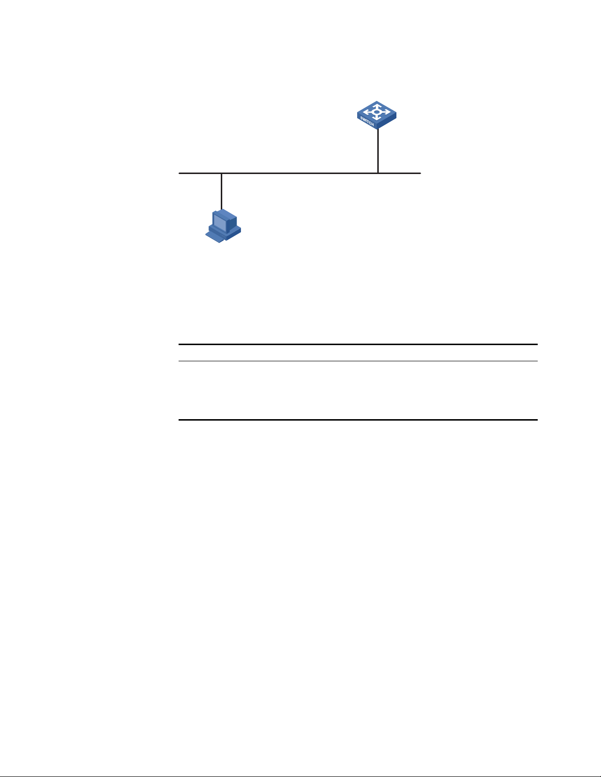
Figure 1 Logging in from the console port to configure Telnet login
As shown in Figure 1, use a console cable to connect the serial port of your
PC/terminal to the console port of the switch. Log into the switch from the AUX
user interface on the console port to configure Telnet login. The current user level
is manage level (level 3).
Product series Software version Hardware version
Switch 5500 Release V03.02.04 All versions
Switch 5500G Release V03.02.04 All versions
Switch 4500 Release V03.03.00 All versions
Switch 4210 Release V03.01.00 All versions
Configuration Procedure
■ Configure common attributes for Telnet login
# Set the level of commands accessible to the VTY 0 user to 2.
[3Com] user-interface vty 0
[3Com-ui-vty0] user privilege level 2
# Enable the Telnet service on VTY 0.
[3Com-ui-vty0] protocol inbound telnet
# Set the number of lines that can be viewed on the screen of the VTY 0 user to
30.
[3Com-ui-vty0] screen-length 30

14 CHAPTER 1: LOGIN CONFIGURATION GUIDE
# Set the history command buffer size to 20 for VTY 0.
[3Com-ui-vty0] history-command max-size 20
# Set the idle-timeout time of VTY 0 to 6 minutes.
[3Com-ui-vty0] idle-timeout 6
■ Configure an authentication mode for Telnet login
The following three authentication modes are available for Telnet login: none,
password, and scheme.
The configuration procedures for the three authentication modes are described
below:
1 Configure not to authenticate Telnet users on VTY 0.
[3Com] user-interface vty 0
[3Com-ui-vty0] authentication-mode none
2 Configure password authentication for Telnet login on VTY 0, and set the
password to 123456 in plain text.
[3Com] user-interface vty 0
[3Com-ui-vty0] authentication-mode password
[3Com-ui-vty0] set authentication password simple 123456
3 Configure local authentication in scheme mode for login users.
# Create a local user named guest and enter local user view.
[3Com] local-user guest
# Set the authentication password to 123456 in plain text.
[3Com-luser-guest] password simple 123456
# Set the service type to Telnet and the user level to 2 for the user guest.
[3Com-luser-guest] service-type telnet level 2
[3Com-luser-guest] quit
# Enter VTY 0 user interface view.
[3Com] user-interface vty 0
# Set the authentication mode to scheme for Telnet login on VTY 0.
[3Com-ui-vty0] authentication-mode scheme
[3Com-ui-vty0] quit
# Specify the domain system as the default domain, and configure the domain to
adopt local authentication in scheme mode.
[3Com] domain default enable system
[3Com] domain system
[3Com-isp-system] scheme local

Logging In Through Telnet 15
Complete Configuration ■ Telnet login configuration with the authentication mode being none
user-interface vty 0
authentication-mode none
user privilege level 2
history-command max-size 20
idle-timeout 6 0
screen-length 30
protocol inbound telnet
■ Telnet login configuration with the authentication mode being password
user-interface vty 0
user privilege level 2
set authentication password simple 123456
history-command max-size 20
idle-timeout 6 0
screen-length 30
protocol inbound telnet
■ Telnet login configuration with the authentication mode being scheme
#
domain system
#
local-user guest
password simple 123456
level 3
#
user-interface vty 0
authentication-mode scheme
user privilege level 2
history-command max-size 20
idle-timeout 6 0
screen-length 30
protocol inbound telnet
Precautions None
Logging In Through Te ln et
You can telnet to your switch to manage and maintain it remotely.
16 CHAPTER 1: LOGIN CONFIGURATION GUIDE
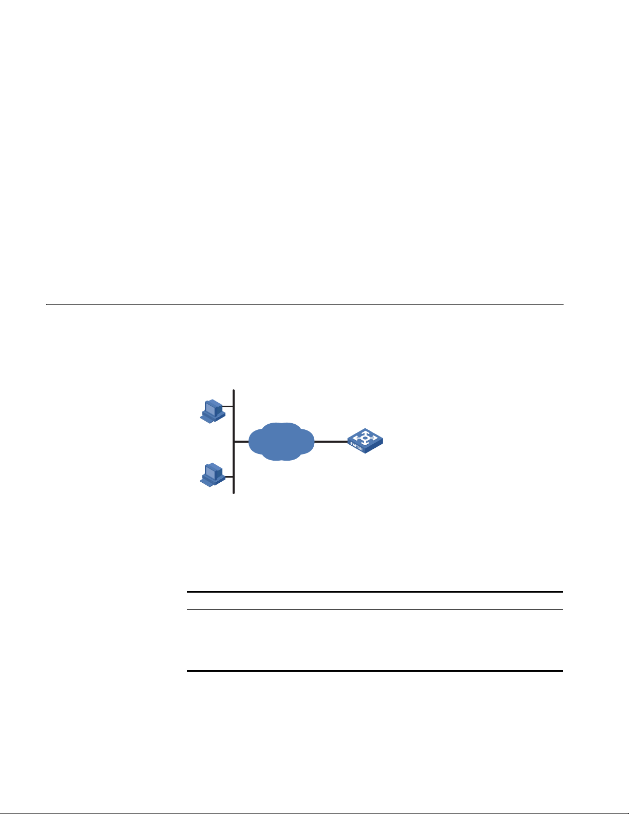
Network Diagram Figure 2 Telneting to the switch to configure console login
Ethernet
User PC running Telnet
Ethernet1/0/ 1
Networking and
Configuration
Requirements
Applicable Products
Configuration Procedure
As shown in Figure 2, telnet to the switch to configure console login. The current
user level is manage level (level 3).
Product series Software version Hardware version
Switch 5500 Release V03.02.04 All versions
Switch 5500G Release V03.02.04 All versions
Switch 4500 Release V03.03.00 All versions
Switch 4210 Release V03.01.00 All versions
■ Common configuration for console login
# Specify the level of commands accessible to the AUX 0 user interface to 2.
[3Com] user-interface aux 0
[3Com-ui-aux0] user privilege level 2
# Set the baud rate of the console port to 19200 bps.
[3Com-ui-aux0] speed 19200
# Set the number of lines that can be viewed on the screen of the AUX 0 user to
30.
[3Com-ui-aux0] screen-length 30
# Set the history command buffer size to 20 for AUX 0.
[3Com-ui-aux0] history-command max-size 20
# Set the idle-timeout time of AUX 0 to 6 minutes.
[3Com-ui-aux0] idle-timeout 6
■ Configure the authentication mode for console login

Logging In Through Telnet 17
The following three authentication modes are available for console login: none,
password, and scheme. The configuration procedures for the three authentication
modes are described below:
1 Configure not to authenticate console login users.
[3Com] user-interface aux 0
[3Com-ui-aux0] authentication-mode none
2 Configure password authentication for console login, and set the password to
123456 in plain text.
[3Com] user-interface aux 0
[3Com-ui-aux0] authentication-mode password
[3Com-ui-aux0] set authentication password simple 123456
3 Configure local authentication in scheme mode for console login.
# Create a local user named guest and enter local user view.
[3Com] local-user guest
# Set the authentication password to 123456 in plain text.
[3Com-luser-guest] password simple 123456
# Set the service type to Terminal and the user level to 2 for the user guest.
[3Com-luser-guest] service-type terminal level 2
[3Com-luser-guest] quit
# Enter AUX 0 user interface view.
[3Com] user-interface aux 0
# Set the authentication mode to scheme for console login.
[3Com-ui-aux0] authentication-mode scheme
Complete Configuration ■ Console login configuration with the authentication mode being none
#
user-interface aux 0
user privilege level 2
history-command max-size 20
idle-timeout 6 0
speed 19200
screen-length 30
■ Console login configuration with the authentication mode being password
#
user-interface aux 0
authentication-mode password
user privilege level 2
set authentication password simple 123456
history-command max-size 20
idle-timeout 6 0
speed 19200
screen-length 30
18 CHAPTER 1: LOGIN CONFIGURATION GUIDE
Switch
10.110.100.46
Host A
IP netw ork
Host B
10.110.100.52
■ Console login configuration with the authentication mode being scheme
#
local-user guest
password simple 123456
service-type terminal
level 2
#
user-interface aux 0
authentication-mode scheme
user privilege level 2
history-command max-size 20
idle-timeout 6 0
speed 19200
screen-length 30
Precautions None
Configuring Login Access Control
Network Diagram Figure 3 Network diagram for login access control
Networking and
Configuration
As shown in Figure 3, configure the switch to allow only Telnet/SNMP/WEB users
at 10.110.100.52 and 10.110.100.46 to log in.
Requirements
Applicable Products
Product series Software version Hardware version
Switch 5500 Release V03.02.04 All versions
Switch 5500G Release V03.02.04 All versions
Switch 4500 Release V03.03.00 All versions
Switch 4210 Release V03.01.00 All versions
Configuration Procedure # Create basic ACL 2000 and enter basic ACL view.
[3Com] acl number 2000 match-order config
[3Com-acl-basic-2000]
# Define ACL rules to allow only Telnet/SNMP/WEB users at 10.110.100.52 and
10.110.100.46 to log into the switch.

Configuring Login Access Control 19
[3Com-acl-basic-2000] rule 1 permit source 10.110.100.52 0
[3Com-acl-basic-2000] rule 2 permit source 10.110.100.46 0
[3Com-acl-basic-2000] rule 3 deny source any
[3Com-acl-basic-2000] quit
# Reference ACL 2000 to control Telnet login by source IP address.
[3Com] user-interface vty 0 4
[3Com-ui-vty0-4] acl 2000 inbound
# Reference ACL 2000 to control SNMP login by source IP address.
[3Com] snmp-agent community read aaa acl 2000
[3Com] snmp-agent group v2c groupa acl 2000
[3Com] snmp-agent usm-user v2c usera groupa acl 2000
# Reference ACL 2000 to control WEB login by source IP address.
[3Com] ip http acl 2000
Complete Configuration ■ Configuration for Telnet login control by source IP address
#
acl number 2000
rule 1 permit source 10.110.100.52 0
rule 2 permit source 10.110.100.46 0
rule 3 deny
#
user-interface vty 0 4
acl 2000 inbound
■ Configuration for SNMP login control by source IP address
#
acl number 2000
rule 1 permit source 10.110.100.52 0
rule 2 permit source 10.110.100.46 0
rule 3 deny
#
snmp-agent community read aaa acl 2000
snmp-agent group v2c groupa acl 2000
snmp-agent usm-user v2c usera groupa acl 2000
■ Configuration for WEB login control by source IP address
#
ip http acl 2000
#
acl number 2000
rule 1 permit source 10.110.100.52 0
rule 2 permit source 10.110.100.46 0
rule 3 deny
Precautions None

20 CHAPTER 1: LOGIN CONFIGURATION GUIDE
2
Server
Eth1/0/12Eth1/0/11
Et h1/0 /10
Eth1/0/1 Eth1/0/2
Et h1/0 /3
Server Host
Host
VLAN CONFIGURATION GUIDE
Configuring Port-Based VLAN
Network Diagram
Networking and
Configuration
Requirements
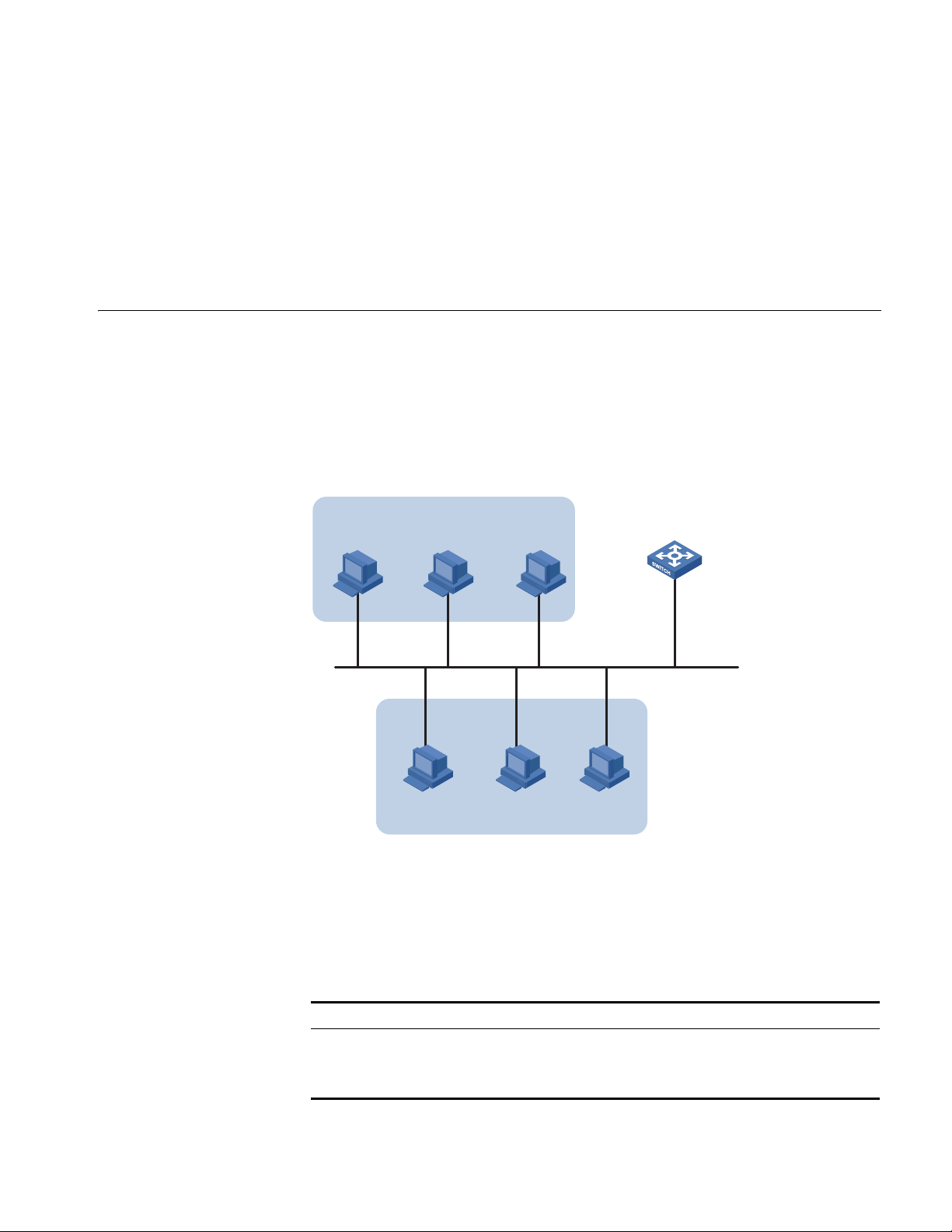
The VLAN technology allows you to divide a broadcast LAN into multiple distinct
broadcast domains, each as a virtual workgroup. Port-based VLAN is the simplest
approach to VLAN implementation. The idea is to assign the ports on a switch to
different VLANs, confining the propagation of the packets received on a port
within the particular VLAN. Thus, separation of broadcast domains and division of
virtual groups are achieved.
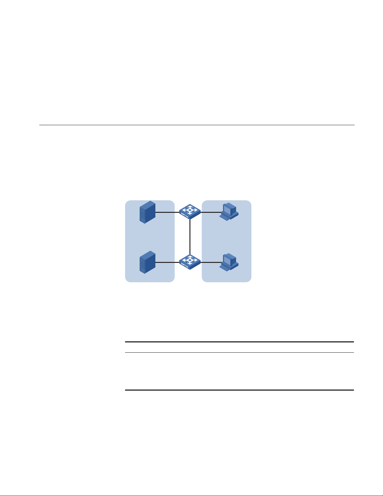
Figure 4 Network diagram for port-based VLAN configuration
Switch A and Switch B are connected each to a server and workstation. To
guarantee data security for the servers, you need to isolate the servers from the
workstations by creating VLANs. Allow the devices within a VLAN to communicate
with each other but not directly with the devices in another VLAN.
Applicable Products
Configuration Procedure # Create VLAN 101 on Switch A and add Ethernet 1/0/1 to VLAN 101.
Product series Software version Hardware version
Switch 5500 Release V03.02.04 All versions
Switch 5500G Release V03.02.04 All versions
Switch 4500 Release V03.03.00 All versions
Switch 4210 Release V03.01.00 All versions
[SwitchA] vlan 101
[SwitchA-vlan101] port Ethernet 1/0/1
# Create VLAN 201 on Switch A and add Ethernet 1/0/2 to VLAN 201.

22 CHAPTER 2: VLAN CONFIGURATION GUIDE
[SwitchA-vlan101] quit
[SwitchA] vlan 201
[SwitchA-vlan201] port Ethernet 1/0/2
# Configure Ethernet 1/0/3 of Switch A to be a trunk port and to permit the
packets carrying the tag of VLAN 101 or VLAN 201 to pass through.
[SwitchA-vlan201] quit
[SwitchA] interface Ethernet 1/0/3
[SwitchA-Ethernet1/0/3] port link-type trunk
[SwitchA-Ethernet1/0/3] port trunk permit vlan 101 201
# Create VLAN 101 on Switch B, and add Ethernet 1/0/11 to VLAN 101.
[SwitchB] vlan 101
[SwitchB-vlan101] port Ethernet 1/0/11
# Create VLAN 201 on Switch B, and add Ethernet 1/0/12 to VLAN 201.
[SwitchB-vlan101] quit
[SwitchB] vlan 201
[SwitchB-vlan201] port Ethernet 1/0/12
# Configure Ethernet 1/0/10 of Switch B to be a trunk port and to permit the
packets carrying the tag of VLAN 101 or VLAN 201 to pass through.
[SwitchB-vlan201] quit
[SwitchB] interface Ethernet 1/0/10
[SwitchB-Ethernet1/0/10] port link-type trunk
[SwitchB-Ethernet1/0/10] port trunk permit vlan 101 201
Complete Configuration ■ Configuration on Switch A
#
vlan 101
#
vlan 201
#
interface Ethernet1/0/1
port access vlan 101
#
interface Ethernet1/0/2
port access vlan 201
#
interface Ethernet1/0/3
port link-type trunk
port trunk permit vlan 1 101 201
■ Configuration on Switch B
#
vlan 101
#
vlan 201
#
interface Ethernet1/0/10
port link-type trunk
port trunk permit vlan 1 101 201
Configuring Protocol-Based VLAN 23
IP Host
Eth 1/0/10
Et h1/0 /11 Et h1/0 /12
Workroom
AppleTalk Host
IP Server AppleTalk Server
#
interface Ethernet1/0/11
port access vlan 101
#
interface Ethernet1/0/12
port access vlan 201
Precautions ■ After you assign the servers and the workstations to different VLANs, they
cannot communicate with each other. For them to communicate, you need to
configure a Layer 3 VLAN interface for each of them on the switches.
■ After you telnet to an Ethernet port on a switch to make configuration, do not
remove the port from its current VLAN. Otherwise, your Telnet connection will
be disconnected.
Configuring Protocol-Based VLAN
Network Diagram
Protocol-based VLAN, or protocol VLAN, is another approach to VLAN
implementation other than port-based VLAN. With protocol VLAN, the switch
compares each packet received without a VLAN tag against the protocol templates
based on the encapsulation format and the specified field. If a match is found, the
switch tags the packet with the corresponding VLAN ID. Thus, the switch can
assign packets to a VLAN by protocol.
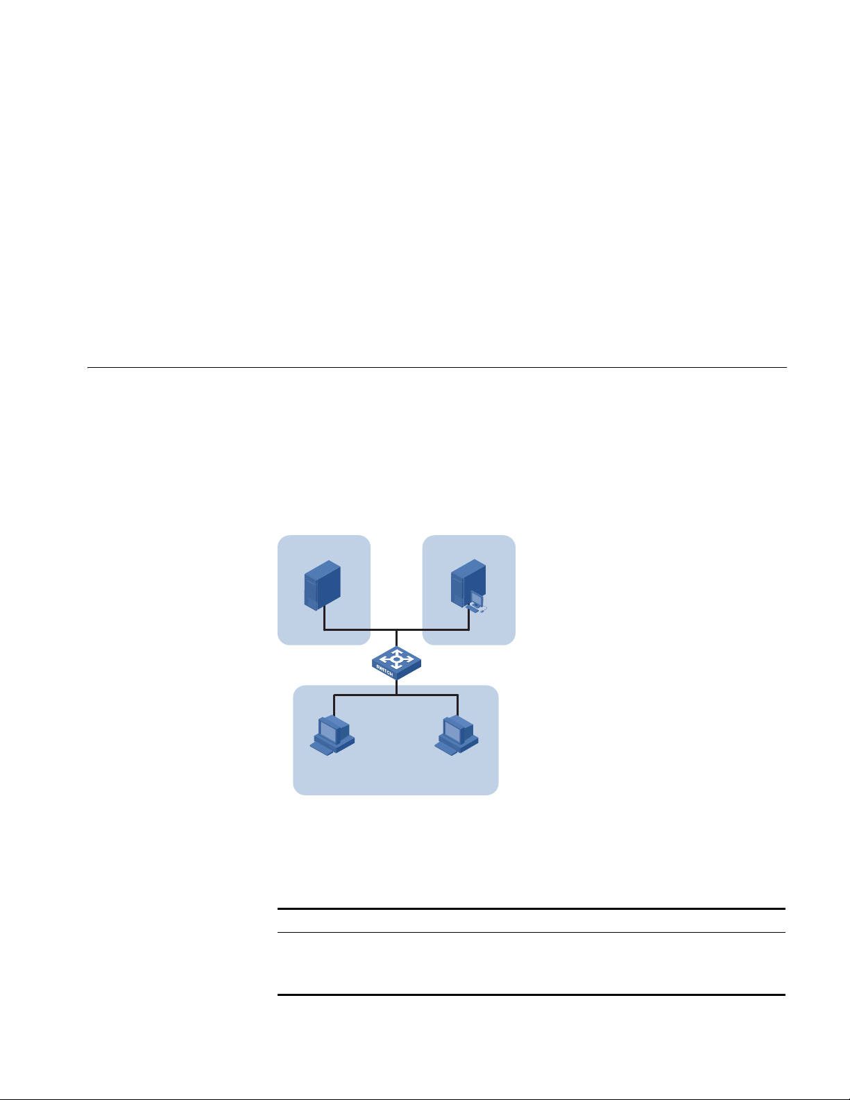
Figure 5 Network diagram for protocol-based VLAN configuration
Networking and
Configuration
Requirements
Applicable Products
Configure the switch to automatically assign IP packets and Appletalk packets of
the workroom to different VLANs, ensuring that the workstations can
communicate with their respective servers properly.
Product series Software version Hardware version
Switch 5500 Release V03.02.04 All versions
Switch 5500G Release V03.02.04 All versions
Switch 4500 Release V03.03.00 All versions

24 CHAPTER 2: VLAN CONFIGURATION GUIDE
Configuration Procedure # Create VLAN 100 and VLAN 200; add Ethernet 1/0/11 to VLAN 100 and
Ethernet 1/0/12 to VLAN 200.
1 Create VLAN 100 and add Ethernet1/0/11 to VLAN 100.
[3Com] vlan 100
[3Com-vlan100] port Ethernet 1/0/11
2 Create VLAN 200 and add Ethernet 1/0/12 to VLAN 200.
[3Com-vlan100] quit
[3Com] vlan 200
[3Com-vlan200] port Ethernet 1/0/12
# Configure protocol templates and bind them to ports.
3 Create a protocol template for VLAN 200 to carry Appletalk and a protocol
template for VLAN 100 to carry IP.
[3Com-vlan200] protocol-vlan at
[3Com-vlan200] quit
[3Com] vlan 100
[3Com-vlan100] protocol-vlan ip
4 Create a user-defined protocol template for VLAN 100 to carry ARP for IP
communication, assuming that Ethernet_II encapsulation is used.
[3Com-vlan100] protocol-vlan mode ethernetii etype 0806
5 Configure Ethernet 1/0/10 to be a hybrid port and to remove the outer VLAN tag
6 Bind Ethernet 1/0/10 to protocol template 0 and protocol template 1 of VLAN
n
Complete Configuration #
when forwarding packets of VLAN 100 and VLAN 200.
[3Com-vlan100] quit
[3Com] interface Ethernet 1/0/10
[3Com-Ethernet1/0/10] port link-type hybrid
[3Com-Ethernet1/0/10] port hybrid vlan 100 200 untagged
100, and protocol template 0 of VLAN 200.
When configuring a protocol template, you can assign a number to the template.
If you fail to do that, the system automatically assigns the lowest available number
to the template. Thus, in this configuration example, the two protocol templates
for VLAN 100 are automatically numbered 0 and 1, and the protocol template for
VLAN 200 is numbered 0.
[3Com-Ethernet1/0/10] port hybrid protocol-vlan vlan 100 0 to 1
[3Com-Ethernet1/0/10] port hybrid protocol-vlan vlan 200 0
vlan 100
protocol-vlan 0 ip
protocol-vlan 1 mode ethernetii etype 0806
#
vlan 200
protocol-vlan 0 at
#
interface Ethernet1/0/10
port link-type hybrid
port hybrid vlan 1 100 200 untagged
port hybrid protocol-vlan vlan 100 0
port hybrid protocol-vlan vlan 100 1

Configuring Protocol-Based VLAN 25
port hybrid protocol-vlan vlan 200 0
#
interface Ethernet1/0/11
port access vlan 100
#
interface Ethernet1/0/12
port access vlan 200
Precautions Because IP depends on ARP for address resolution in Ethernet, you are
recommended to configure the IP and ARP templates in the same VLAN and
associate them with the same port to prevent communication failure.
Up to five protocol templates can be bound to a port.

26 CHAPTER 2: VLAN CONFIGURATION GUIDE
3
Vlan-int1
172.16.1.1/ 24
172.16.2.1/ 24 sub
172.16.1.0/24
172.16.1.2/24
172.16.2.0/24
172.16. 2.2/24
Host A
Host B
Switch
IP ADDRESS CONFIGURATION GUIDE
IP Address Configuration Guide
Network Diagram
If you want to manage a remote Ethernet switch through network management
or telnet, you need to configure an IP address for the remote switch and ensure
that the local device and the remote switch are reachable to each other.
A 32-bit IP address identifies a host on the Internet. Generally, a VLAN interface on
a switch is configured with one primary and four secondary IP addresses.
Figure 6 Network diagram for IP address configuration
Networking and
Configuration
Requirements
Applicable Products
As shown in the above figure, the port in VLAN 1 on Switch is connected to a LAN
in which hosts belong to two network segments: 172.16.1.0/24 and
172.16.2.0/24. It is required to enable the hosts in the LAN to communicate with
external networks through Switch, and to enable the hosts in the two network
segments to communicate with each other.
Product series Software version Hardware version
Switch 5500 Release V03.02.04 All versions
Switch 5500G Release V03.02.04 All versions
Switch 4500 Release V03.03.00 All versions

28 CHAPTER 3: IP ADDRESS CONFIGURATION GUIDE
Configuration Procedure Assign a primary and secondary IP addresses to VLAN-interface 1 of Switch to
ensure that all the hosts on the LAN can access external networks through Switch.
Set Switch as the gateway on all the hosts of the two network segments to ensure
that they can communicate with each other.
# Assign a primary IP address and a secondary IP address to VLAN-interface 1.
<Switch> system-view
[Switch] interface Vlan-interface 1
[Switch-Vlan-interface1] ip address 172.16.1.1 255.255.255.0
[Switch-Vlan-interface1] ip address 172.16.2.1 255.255.255.0 sub
# Set the gateway address to 172.16.1.1 on the hosts in subnet 172.16.1.0/24,
and to 172.16.2.1 on the hosts in subnet 172.16.2.0/24.
# Ping Host B on Host A to verify the connectivity.
Complete Configuration #
interface Vlan-interface 1
ip address 172.16.1.1 255.255.255.0
ip address 172.16.2.1 255.255.255.0 sub
#
Precautions ■ You can assign at most five IP addresses to an interface, among which one is
the primary IP address and the others are secondary IP addresses. A newly
specified primary IP address overwrites the previous one.
■ The primary and secondary IP addresses of an interface cannot reside on the
same network segment; an IP address of a VLAN interface must not be on the
same network segment as that of a loopback interface on a device.
■ A VLAN interface cannot be configured with a secondary IP address if the
interface has obtained an IP address through BOOTP or DHCP.
4
VOICE VLAN CONFIGURATION GUIDE
Configuring Voice VLAN
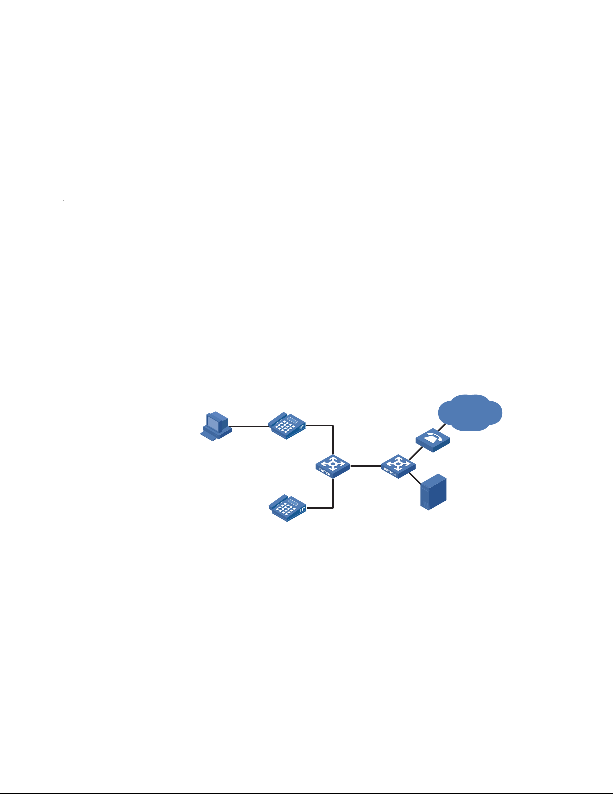
Network Diagram
In automatic mode, the switch configured with voice VLAN checks the source
MAC address of each incoming packet against the voice device vendor OUI. If a
match is found, the switch assigns the receiving port to the voice VLAN and tags
the packet with the voice VLAN ID automatically.
When the port joins the voice VLAN, a voice VLAN aging timer starts. If no voice
packets have been received before the timer expires, the port leaves the voice
VLAN.
In manual mode, you need to manually assign a port to or remove the port from
the voice VLAN.
Figure 7 Network diagram for voice VLAN in automatic mode
PC
IP Phone1
(Tag)
000f-e234-1234
Gateway
Eth1/0/1
SwitchA SwitchB
Eth1/0/2
Voice
VoIP Network
Networking and
Configuration
Requirements
Server
IP Phone2
(Untag)
Oui:000f-2200-0000
As shown in Figure 7, PC is connected to Ethernet 1/0/1 of Switch A through IP
phone 1, and IP phone 2 is connected to Ethernet 1/0/2 of Switch A. IP phone 1
sends out voice traffic with the tag of the voice VLAN, while IP phone 2 sends out
voice traffic without any VLAN tag. Configure voice VLAN to satisfy the following
requirements:
■ VLAN 2 functions as the voice VLAN for transmitting voice traffic, and set the
aging time of the voice VLAN to 100 minutes. VLAN 6 transmits user service
data.
■ Ethernet 1/0/1 and Ethernet 1/0/2 can recognize voice traffic automatically.
Service data from PC and voice traffic are assigned to different VLANs and then
transmitted to the server and the voice gateway respectively through Switch B.

30 CHAPTER 4: VOICE VLAN CONFIGURATION GUIDE
■ As the OUI address of IP phone 2 is not in the default voice device vendor OUI
list of the switch, you need to add its OUI address 000f-2200-0000. In addition,
configure its description as IP Phone2.
Applicable Products
Product series Software version Hardware version
Switch 5500 Release V03.02.04 All versions
Switch 5500G Release V03.02.04 All versions
Switch 4500 Release V03.03.00 All versions
Configuration Procedure # Create VLAN 2 and VLAN 6.
<SwitchA> system-view
[SwitchA] vlan 2
[SwitchA-vlan2] quit
[SwitchA] vlan 6
[SwitchA-vlan6] quit
# Set the aging time for the voice VLAN.
[SwitchA] voice vlan aging 100
# Add 000f-2200-0000 to the OUI address list and configure its description as IP
Phone2.
[SwitchA] voice vlan mac-address 000f-2200-0000 mask ffff-ff00-0000
description IP Phone2
# Configure VLAN 2 as the voice VLAN.
[SwitchA] voice vlan 2 enable
# Set the voice VLAN operation mode on Ethernet 1/0/1 to automatic. This step is
optional, because the default operation mode of the voice VLAN is automatic.
[SwitchA] interface Ethernet 1/0/1
[SwitchA-Ethernet1/0/1] voice vlan mode auto
# Configure Ethernet 1/0/1 as a trunk port.
[SwitchA-Ethernet1/0/1] port link-type trunk
# Set VLAN 6 as the default VLAN of Ethernet 1/0/1 and configure Ethernet 1/0/1
to permit the packets of VLAN 6 to pass through. (PC data will be transmitted in
the VLAN.)
n
[SwitchA-Ethernet1/0/1] port trunk pvid vlan 6
[SwitchA-Ethernet1/0/1] port trunk permit vlan 6
# Enable voice VLAN on Ethernet 1/0/1.
[SwitchA-Ethernet1/0/1] voice vlan enable
■ After the configuration above, PC data is automatically assigned to the default
VLAN of Ethernet 1/0/1 (namely the service VLAN) for transmission. When IP

Configuring Voice VLAN 31
phone traffic arrives at Ethernet 1/0/1, the port automatically permits the voice
VLAN and transmits the voice traffic with the voice VLAN tag, so that the IP
phone can receive packets normally.
■ You can set Ethernet 1/0/1 as a hybrid or trunk port following the same
procedure. In either case, you need to set the service VLAN as the default
VLAN. As for voice traffic, when IP phone traffic arrives at the port, the port
automatically permits the voice VLAN and transmits the traffic with the voice
VLAN tag.
# Set the voice VLAN operation mode of Ethernet 1/0/2 to manual. The operation
mode must be manual because IP phone 2 can only send out untagged voice
traffic.
[SwitchA-Ethernet1/0/1] quit
[SwitchA] interface Ethernet 1/0/2
[SwitchA-Ethernet1/0/2] undo voice vlan mode auto
# Configure Ethernet 1/0/2 to be an access port and permit the voice VLAN.
[SwitchA-Ethernet1/0/2] port access vlan 2
n
Complete Configuration
# Enable voice VLAN on Ethernet 1/0/2.
[SwitchA-Ethernet1/0/2] voice vlan enable
■ You can set Ethernet 1/0/2 as a trunk or hybrid port. In either case, configure
the voice VLAN as the default VLAN and configure the port to remove the
VLAN tag when forwarding traffic with the voice VLAN tag.
■ If traffic from IP phone 2 is tagged, configure Ethernet 1/0/2 as a trunk or
hybrid port where the default VLAN cannot be set to VLAN 20 and the packets
of VLAN 20 must be sent with the VLAN tag.
#
vlan 1 to 2
#
vlan 6
#
interface Ethernet1/0/1
port link-type trunk
port trunk permit vlan 1 6
port trunk pvid vlan 6
voice vlan enable
#
interface Ethernet1/0/2
port access vlan 2
undo voice vlan mode auto
voice vlan enable
#
voice vlan aging 100
voice vlan mac-address 000f-2200-0000 mask ffff-ff00-0000 descripti
on IP Phone2
voice vlan 2 enable

32 CHAPTER 4: VOICE VLAN CONFIGURATION GUIDE
Precautions ■ You cannot add a port operating in automatic mode to the voice VLAN
manually. Therefore, if you configure a VLAN as a voice VLAN and a protocol
VLAN at the same time, you will be unable to associate the protocol VLAN with
such a port. Refer to “Configuring Protocol-Based VLAN” on page 23 for
description on protocol VLAN.
■ You cannot set the voice VLAN as the default VLAN on a port in automatic
mode.
■ The switch supports only one voice VLAN.
■ You cannot enable voice VLAN on a port configured with the Link Aggregation
Control Protocol (LACP).
■ Only a static VLAN can be configured as a voice VLAN.
■ When the number of ACL rules applied to a port reaches the upper threshold,
enabling voice VLAN on the port fails. You can use the display voice vlan
error-info command to locate such ports.
■ In the voice VLAN operating in security mode, the device allows only the
packets whose source address matches a recognizable voice device vendor OUI
to pass through. All other packets, including authentication packets such as
802.1x authentication packets, will be dropped. Therefore, you are
recommended not to transmit both voice data and service data in the voice
VLAN. If that is needed, disable the security mode of the voice VLAN.

GVRP CONFIGURATION GUIDE
5
Configuring GVRP GVRP enables a switch to propagate local VLAN registration information to other
participant switches and dynamically update the VLAN registration information
from other switches to its local database about active VLAN members and through
which port they can be reached. GVRP ensures that all switches on a bridged LAN
maintain the same VLAN registration information, while less manual configuration
workload is involved.
Network Diagram
Networking and
Configuration
Requirements
Figure 8 Network diagram for GVRP configuration
Eth1/0/1
VLAN 5
Switch A
Eth1/0/2 Eth1/0/3
Switch C Switch E
Eth1/0/1 Eth1/0/1
Switch D
VLAN 8
Switch B
Eth 1/0/2
Eth1/0/ 1Eth1/0/1
VLAN 5
VLAN 7
As shown in Figure 8, all the switches in the network are Switch 5500s.
■ All the involved Ethernet ports on the switches are configured to be trunk ports
and permit all the VLANs to pass through.
■ GVRP is enabled for all the switches globally and for all the ports on them.
■ Configure static VLAN 5 for Switch C, static VLAN 8 for Switch D, and static
VLAN 5 and static VLAN 7 for Switch E. Switch A and Switch B are not
configured with static VLANs.
■ Set the registration mode of Ethernet 1/0/1 on Switch E to fixed, and display
dynamic VLAN registration information of Switch A, Switch B, and Switch E.
Applicable Products
■ Set the registration mode of Ethernet 1/0/1 on Switch E to forbidden, and
display dynamic VLAN registration information of Switch A, Switch B, and
Switch E.
Product series Software version Hardware version
Switch 5500 Release V03.02.04 All versions
Switch 5500G Release V03.02.04 All versions
Switch 4500 Release V03.03.00 All versions
Switch 4210 Release V03.01.00 All versions

34 CHAPTER 5: GVRP CONFIGURATION GUIDE
Configuration Procedure ■ Configure Switch A
# Enable GVRP globally.
<SwitchA> system-view
[SwitchA] gvrp
# Configure Ethernet 1/0/1 to be a trunk port and to permit the packets of all the
VLANs to pass through.
[SwitchA] interface Ethernet 1/0/1
[SwitchA-Ethernet1/0/1] port link-type trunk
[SwitchA-Ethernet1/0/1] port trunk permit vlan all
# Enable GVRP on Ethernet 1/0/1.
[SwitchA-Ethernet1/0/1] gvrp
[SwitchA-Ethernet1/0/1] quit
# Configure Ethernet 1/0/2 to be a trunk port and to permit the packets of all the
VLANs to pass through.
[SwitchA] interface Ethernet 1/0/2
[SwitchA-Ethernet1/0/2] port link-type trunk
[SwitchA-Ethernet1/0/2] port trunk permit vlan all
# Enable GVRP on Ethernet 1/0/2.
[SwitchA-Ethernet1/0/2] gvrp
[SwitchA-Ethernet1/0/2] quit
# Configure Ethernet 1/0/3 to be a trunk port and to permit the packets of all the
VLANs to pass through.
[SwitchA] interface Ethernet 1/0/3
[SwitchA-Ethernet1/0/3] port link-type trunk
[SwitchA-Ethernet1/0/3] port trunk permit vlan all
# Enable GVRP on Ethernet 1/0/3.
[SwitchA-Ethernet1/0/3] gvrp
[SwitchA-Ethernet1/0/3] quit
■ Configure Switch B
# Configure Ethernet 1/0/1 and Ethernet 1/0/2 to be trunk ports and to permit the
packets of all the VLANs to pass through. Enable GVRP globally and enable GVRP
on the two ports. # The configuration on Switch B is similar to that on Switch A.
■ Configure Switch C
# Create VLAN 5.
<SwitchC> system-view
[SwitchC] vlan5
[SwitchC-vlan5]

Configuring GVRP 35
# Configure Ethernet 1/0/1 to be a trunk port and to permit the packets of all the
VLANs to pass through. Enable GVRP globally and enable GVRP on the port. # The
configuration on Switch C is similar to that on Switch A.
n
For simplicity, the following provides only configuration steps. For configuration
commands, refer to “Configure Switch C” on page 34.
■ Configure Switch D
# Configure Ethernet 1/0/1 to be a trunk port and to permit the packets of all the
VLANs to pass through. Enable GVRP globally and enable GVRP on the port.
# Create VLAN 8.
■ Configure Switch E
# Configure Ethernet 1/0/1 to be a trunk port and to permit the packets of all the
VLANs to pass through. Enable GVRP globally and enable GVRP on the port.
# Create VLAN 5 and VLAN 7.
■ Display the static VLAN registration information on Switch A, Switch B, and
Switch C.
# Display the dynamic VLAN information on Switch A.
[SwitchA] display vlan dynamic
Total 3 dynamic VLAN exist(s).
The following dynamic VLANs exist:
5, 7, 8,
# Display the dynamic VLAN information on Switch B.
[SwitchB] display vlan dynamic
Total 3 dynamic VLAN exist(s).
The following dynamic VLANs exist:
5, 7, 8,
# Display the dynamic VLAN information on Switch E.
[SwitchE] display vlan dynamic
Total 1 dynamic VLAN exist(s).
The following dynamic VLANs exist:
8
■ Set the registration mode of Ethernet 1/0/1 on Switch E to fixed, and display
the dynamic VLAN registration information on Switch A, Switch B, and Switch
E.
# Set the registration mode of Ethernet 1/0/1 on Switch E to fixed.
[SwitchE] interface Ethernet 1/0/1
[SwitchE-Ethernet1/0/1] gvrp registration fixed
# Display the dynamic VLAN information on Switch A.

36 CHAPTER 5: GVRP CONFIGURATION GUIDE
[SwitchA] display vlan dynamic
Total 3 dynamic VLAN exist(s).
The following dynamic VLANs exist:
5, 7, 8,
# Display the dynamic VLAN information on Switch B.
[SwitchB] display vlan dynamic
Total 3 dynamic VLAN exist(s).
The following dynamic VLANs exist:
5, 7, 8,
# Display the dynamic VLAN information on Switch E.
[SwitchE-Ethernet1/0/1] display vlan dynamic
No dynamic vlans exist!
■ Set the registration mode of Ethernet 1/0/1 on Switch E to forbidden, and
display the dynamic VLAN registration information on Switch A, Switch B, and
Switch E.
# Set the registration mode of Ethernet 1/0/1 on Switch E to forbidden.
[SwitchE-Ethernet1/0/1] gvrp registration forbidden
# Display the dynamic VLAN information on Switch A.
[SwitchA] display vlan dynamic
Total 2 dynamic VLAN exist(s).
The following dynamic VLANs exist:
5, 8,
# Display the dynamic VLAN information on Switch B.
[SwitchB] display vlan dynamic
Total 2 dynamic VLAN exist(s).
The following dynamic VLANs exist:
5, 8,
# Display the dynamic VLAN information on Switch E.
[SwitchE] display vlan dynamic
No dynamic vlans exist!
Complete Configuration ■ Configuration on Switch A
#
gvrp
#
interface Ethernet1/0/1
port link-type trunk
port trunk permit vlan all
gvrp
#
interface Ethernet1/0/2
port link-type trunk
port trunk permit vlan all
gvrp

#
interface Ethernet1/0/3
port link-type trunk
port trunk permit vlan all
gvrp
■ Configuration on Switch B
#
gvrp
#
interface Ethernet1/0/1
port link-type trunk
port trunk permit vlan all
gvrp
#
interface Ethernet1/0/2
port link-type trunk
port trunk permit vlan all
gvrp
■ Configuration on Switch C
#
gvrp
#
vlan 5
#
interface Ethernet1/0/1
port link-type trunk
port trunk permit vlan all
gvrp
Configuring GVRP 37
■ Configuration on Switch D
#
gvrp
#
vlan 8
#
interface Ethernet1/0/1
port link-type trunk
port trunk permit vlan all
gvrp
■ Configuration on Switch E
#
gvrp
#
vlan 5
#
vlan 7
#
interface Ethernet1/0/1
port link-type trunk
port trunk permit vlan all
gvrp registration forbidden
gvrp

38 CHAPTER 5: GVRP CONFIGURATION GUIDE
Precautions ■ The port trunk permit vlan all command is designed for GVRP only. To
prevent users of unauthorized VLANs from accessing restrictive resources from
a port, do not use the command when GVRP is disabled on the port.
■ Before enabling GVRP on a port, enable GVRP globally first.
■ Use GVRP only on trunk ports. You cannot change the link type of a trunk port
with GVRP enabled.

6
Eth1/0/1Eth1/0/1
Switch A Switch B
PORT BASIC CONFIGURATION GUIDE
Configuring the Basic Functions of an Ethernet Port
Network Diagram
Networking and
Configuration
Requirements
An Ethernet port on a Switch 5500 can operate in one of the three link types:
■ Access: an access port can belong to only one VLAN and is generally used to
connect to a PC.
■ Trunk: a trunk port can belong to multiple VLANs. It can receive/send packets
of multiple VLANs and is generally used to connect to a switch.
■ Hybrid: a hybrid port can belong to multiple VLANs. It can receive/send packets
of multiple VLANs and can be used to connect to either a switch or a PC.
You can add an Ethernet port to a specified VLAN. After that, the Ethernet port
can forward the packets of the specified VLAN, so that the VLAN on this switch
can intercommunicate with the same VLAN on the peer switch.
Figure 9 Network diagram for Ethernet port configuration
■ Switch A and Switch B are connected through the trunk port Ethernet 1/0/1 on
each side.
■ Specify VLAN 100 as the default VLAN of Ethernet 1/0/1.
Applicable Products
Configuration Procedure
n
■ Configure Ethernet 1/0/1 to permit the packets of VLAN 2, VLAN 6 through
VLAN 50, and VLAN 100 to pass through.
Product series Software version Hardware version
Switch 5500 Release V03.02.04 All versions
Switch 5500G Release V03.02.04 All versions
Switch 4500 Release V03.03.00 All versions
Switch 4210 Release V03.01.00 All versions
■ The following provides only the configuration on Switch A. The configuration
on Switch B is similar to that on Switch A.
■ This configuration example assumes that VLAN 2, VLAN 6 through VLAN 50,
and VLAN 100 have been created.

40 CHAPTER 6: PORT BASIC CONFIGURATION GUIDE
# Enter Ethernet port view of Ethernet 1/0/1.
<3Com> system-view
System View: return to User View with Ctrl+Z.
[3Com] interface ethernet1/0/1
# Configure Ethernet 1/0/1 as a trunk port.
[3Com-Ethernet1/0/1] port link-type trunk
# Configure Ethernet 1/0/1 to permit the packets of VLAN 2, VLAN 6 through
VLAN 50, and VLAN 100 to pass through.
[3Com-Ethernet1/0/1] port trunk permit vlan26to50100
# Configure VLAN 100 as the default VLAN of Ethernet 1/0/1.
[3Com-Ethernet1/0/1] port trunk pvid vlan 100
Complete Configuration #
interface Ethernet1/0/1
port link-type trunk
port trunk permit vlan 1 to26to50100
port trunk pvid vlan 100
#
n
Refer to “VLAN Configuration Guide” on page 21 for the use of hybrid ports.
Precautions Do not configure the port trunk permit vlan all command on a trunk port with
GVRP disabled. To configure the trunk port to permit the packets of multiple
VLANs to pass through, use the port trunk permit vlan vlan-id-list command
instead.

LINK AGGREGATION CONFIGURATION
Switch A
Link aggregation
Switch B
7
Configuring Link Aggregation
Network Diagram
GUIDE
Link aggregation aggregates multiple ports into one logical link, also called an
aggregation group.
Link aggregation allows you to increase bandwidth by distributing
incoming/outgoing traffic on the member ports in the aggregation group. In
addition, it provides reliable connectivity because these member ports can
dynamically back up each other.
Figure 10 Network diagram for link aggregation configuration
Networking and
Configuration
Requirements
Applicable Products
Aggregate Ethernet 1/0/1 through 1/0/3 on Switch A into an aggregation group
and connect the group to Switch B to balance incoming/outgoing traffic among
the member ports.
The example will show you how to configure link aggregation in different
aggregation modes.
Product series Software version Hardware version
Switch 5500 Release V03.02.04 All versions
Switch 5500G Release V03.02.04 All versions
Switch 4500 Release V03.03.00 All versions
Switch 4210 Release V03.01.00 All versions

42 CHAPTER 7: LINK AGGREGATION CONFIGURATION GUIDE
Configuration Procedure
n
configuration on Switch B to implement link aggregation.
1 In manual aggregation mode
# Create manual aggregation group 1.
The example only provides the configuration on Switch A. Perform the same
<3Com> system-view
[3Com] link-aggregation group 1 mode manual
# Add Ethernet 1/0/1 through Ethernet 1/0/3 to aggregation group 1.
[3Com] interface Ethernet1/0/1
[3Com-Ethernet1/0/1] port link-aggregation group 1
[3Com-Ethernet1/0/1] quit
[3Com] interface Ethernet1/0/2
[3Com-Ethernet1/0/2] port link-aggregation group 1
[3Com-Ethernet1/0/2] quit
[3Com] interface Ethernet1/0/3
[3Com-Ethernet1/0/3] port link-aggregation group 1
2 In static LACP aggregation mode
# Create static aggregation group 1.
<3Com> system-view
[3Com] link-aggregation group 1 mode static
# Add Ethernet 1/0/1 through Ethernet 1/0/3 to aggregation group 1.
[3Com] interface Ethernet1/0/1
[3Com-Ethernet1/0/1] port link-aggregation group 1
[3Com-Ethernet1/0/1] quit
[3Com] interface Ethernet1/0/2
[3Com-Ethernet1/0/2] port link-aggregation group 1
[3Com-Ethernet1/0/2] quit
[3Com] interface Ethernet1/0/3
[3Com-Ethernet1/0/3] port link-aggregation group 1
3 In dynamic LACP aggregation mode
# Enable LACP on Ethernet 1/0/1 through Ethernet 1/0/3.
<3Com> system-view
[3Com] interface Ethernet1/0/1
[3Com-Ethernet1/0/1] lacp enable
[3Com-Ethernet1/0/1] quit
[3Com] interface Ethernet1/0/2
[3Com-Ethernet1/0/2] lacp enable
[3Com-Ethernet1/0/2] quit
[3Com] interface Ethernet1/0/3
[3Com-Ethernet1/0/3] lacp enable

Complete Configuration
Configuring Link Aggregation 43
1 In manual aggregation mode
#
link-aggregation group 1 mode manual
#
interface Ethernet1/0/1
port link-aggregation group 1
#
interface Ethernet1/0/2
port link-aggregation group 1
#
interface Ethernet1/0/3
port link-aggregation group 1
#
2 In static LACP aggregation mode
#
link-aggregation group 1 mode static
#
interface Ethernet1/0/1
port link-aggregation group 1
#
interface Ethernet1/0/2
port link-aggregation group 1
#
interface Ethernet1/0/3
port link-aggregation group 1
#
3 In dynamic LACP aggregation mode
#
interface Ethernet1/0/1
lacp enable
#
interface Ethernet1/0/2
lacp enable
#
interface Ethernet1/0/3
lacp enable
#
Precautions ■ If static LACP aggregation or manual aggregation is adopted, you are
recommended not to cross-connect the aggregation member ports at the two
ends to avoid packet loss. For example, if local port 1 is connected to remote
port 2, do not connect local port 2 to remote port 1.
■ Dynamic LACP aggregation mode is not recommended in actual networking
scenarios.
■ The implementation of static aggregation varies by platform software version.
This may result in problems when products using different platform software
versions are interconnected through static aggregation groups. Use the
display version command to view the platform software version.
■ The Switch 4210 supports only the manual aggregation mode.

44 CHAPTER 7: LINK AGGREGATION CONFIGURATION GUIDE

PORT ISOLATION CONFIGURATION
Internet
PC 2
Eth1/0/1
Switch
Eth1/0/3
Eth1/0/4
PC 3
PC 4
Eth1/0/2
8
Configuring Port Isolation
Network Diagram
GUIDE
Port isolation allows you to add a port into an isolation group to isolate Layer-2
and Layer-3 traffic of the port from that of all other ports in the isolation group.
While increasing network security, this allows for great flexibility.
Currently, the Switch 5500 supports only one isolation group; however, the
number of Ethernet ports in the isolation group is not limited.
Figure 11 Network diagram for port isolation configuration
Networking and
Configuration
Requirements
Applicable Products
■ PC2, PC3, and PC4 connect to the switch ports Ethernet 1/0/2, Ethernet 1/0/3,
and Ethernet 1/0/4 respectively.
■ The switch connects to the Internet through Ethernet 1/0/1.
■ Isolate PC2, PC3, and PC4 from each other.
Product series Software version Hardware version
Switch 5500 Release V03.02.04 All versions
Switch 5500G Release V03.02.04 All versions
Switch 4500 Release V03.03.00 All versions
Switch 4210 Release V03.01.00 All versions

46 CHAPTER 8: PORT ISOLATION CONFIGURATION GUIDE
Configuration Procedure # Add Ethernet 1/0/2, Ethernet 1/0/3, and Ethernet 1/0/4 to the isolation group.
<3Com> system-view
System View: return to User View with Ctrl+Z.
[3Com] interface ethernet1/0/2
[3Com-Ethernet1/0/2] port isolate
[3Com-Ethernet1/0/2] quit
[3Com] interface ethernet1/0/3
[3Com-Ethernet1/0/3] port isolate
[3Com-Ethernet1/0/3] quit
[3Com] interface ethernet1/0/4
[3Com-Ethernet1/0/4] port isolate
[3Com-Ethernet1/0/4] quit
[3Com]
# Display information about the ports in the isolation group.
<3Com> display isolate port
Isolated port(s) on UNIT 1:
Ethernet1/0/2, Ethernet1/0/3, Ethernet1/0/4
Complete Configuration #
interface Ethernet1/0/2
port isolate
#
interface Ethernet1/0/3
port isolate
#
interface Ethernet1/0/4
port isolate
#
Precautions ■ Adding to or removing from an isolation group an aggregated port can cause
all other ports in the aggregation group on the device to join or exit the
isolation group automatically.
■ After an aggregated port is removed from its aggregation group, all other
member ports will still stay in the isolation group that they have joined (if any).
■ Removing an aggregation group does not remove its member ports from the
isolation group that they have joined (if any).
■ Adding an isolated port to an aggregation group can cause all the member
ports in the aggregation group to join the isolation group automatically.
■ Cross-device port isolation is supported on the Switch 5500 in an XRN fabric.
This allows ports on different units to join the same isolation group.
■ For the Switch 5500 in an XRN fabric, adding a member port in a cross-device
aggregation group to an isolation group does not cause other member ports to
join the isolation group automatically. For them to join the isolation group, you
need to perform the configuration manually for each of them.

PORT SECURITY CONFIGURATION
Internet
SwitchHost
Eth1/0/1
MAC:0001 -0002- 0003
9
Configuring Port Security autolearn Mode
Network Diagram
GUIDE
In autolearn mode, a port can learn a specified number of MAC addresses and
save those addresses as secure MAC addresses. Once the number of secure MAC
addresses learnt by the port exceeds the upper limit defined by the port-security
max-mac-count command, the port transits to the secure mode. In secure mode,
a port does not save any new secure MAC addresses and permits only packets
whose source addresses are secure MAC address or configured dynamic MAC
addresses.
Figure 12 Network diagram for configuring port security autolearn mode
Networking and
Configuration
Requirements
Applicable Products
Configuration Procedure # Enter system view.
On port Ethernet 1/0/1 of the switch, perform configurations to meet the
following requirements:
■ Allow a maximum of 80 users to access the port without authentication, and
save the automatically learned user MAC addresses as secure MAC addresses.
■ To ensure that the host can access the network, add the MAC address
0001-0002-0003 as a secure MAC address to VLAN 1 on the port.
■ Once the number of secure MAC addresses reaches 80, the port stops MAC
address learning. If any frame with an unknown source MAC address arrives,
intrusion protection is triggered and the port is disabled and kept silent for 30
seconds.
Product series Software version Hardware version
Switch 5500 Release V03.02.04 All versions
Switch 5500G Release V03.02.04 All versions
Switch 4500 Release V03.03.00 All versions
<3Com> system-view
# Enable port security.
[3Com] port-security enable

48 CHAPTER 9: PORT SECURITY CONFIGURATION GUIDE
# Enter Ethernet 1/0/1 port view.
[3Com] interface Ethernet1/0/1
# Set the maximum number of MAC addresses allowed on the port to 80.
[3Com-Ethernet1/0/1] port-security max-mac-count 80
# Set the port security mode to autolearn.
[3Com-Ethernet1/0/1] port-security port-mode autolearn
# Add the MAC address 0001-0002-0003 as a secure MAC address to VLAN 1.
[3Com-Ethernet1/0/1] mac-address security 0001-0002-0003 vlan 1
# Configure the port to be silent for 30 seconds after intrusion protection is
triggered.
[3Com-Ethernet1/0/1] port-security intrusion-mode disableport-temporarily
[3Com-Ethernet1/0/1] quit
[3Com] port-security timer disableport 30
Complete Configuration #
Precautions ■ Before enabling port security, be sure to disable 802.1x and MAC
Configuring Port Security mac-authentication Mode
port-security enable
port-security timer disableport 30
#
interface Ethernet1/0/1
port-security max-mac-count 80
port-security port-mode autolearn
port-security intrusion-mode disableport-temporarily
mac-address security 0001-0002-0003 vlan 1
#
authentication globally.
■ On a port configured with port security, you cannot configure the maximum
number of MAC addresses that the port can learn, reflector port for port
mirroring, fabric port or link aggregation.
In mac-authentication mode, a port performs MAC authentication of users.

Configuring Port Security mac-authentication Mode 49
Internet
Switch
Host
Eth1/0/1
Authentication servers
(192.168. 1.3/24
192.168. 1.2/24 )
Network Diagram Figure 13 Network diagram for configuring port security mac-authentication mode
Networking and
Configuration
Requirements
Applicable Products
Configuration Procedure
The host connects to the switch through the port Ethernet 1/0/1, and the switch
authenticates the host through the RADIUS server. If the authentication is
successful, the host is authorized to access the Internet.
On port Ethernet 1/0/1 of the switch, perform configurations to meet the
following requirements:
■ The switch performs MAC authentication of users.
■ All users belong to the domain aabbcc.net, and each of them uses the MAC
address as username and password for authentication.
■ Whenever a packet fails MAC authentication, intrusion protection is triggered
to filter packets whose source MAC addresses are the same as that of the
packet failing the authentication, ensuring the security of the port.
Product series Software version Hardware version
Switch 5500 Release V03.02.04 All versions
Switch 5500G Release V03.02.04 All versions
Switch 4500 Release V03.03.00 All versions
n
■ The following configurations involve some AAA/RADIUS configuration
commands. For details about the commands, refer to “AAA Configuration” in
the Configuration Guide for your product.
■ Configurations on the user host and the RADIUS server are omitted.
■ Configure RADIUS parameters
# Create a RADIUS scheme named radius1.
<3Com> system-view
[3Com] radius scheme radius1
# Specify the primary RADIUS authentication server and primary RADIUS
accounting server.
[3Com-radius-radius1] primary authentication 192.168.1.3
[3Com-radius-radius1] primary accounting 192.168.1.2

50 CHAPTER 9: PORT SECURITY CONFIGURATION GUIDE
# Specify the secondary RADIUS authentication server and secondary RADIUS
accounting server.
[3Com-radius-radius1] secondary authentication 192.168.1.2
[3Com-radius-radius1] secondary accounting 192.168.1.3
# Set the shared key for message exchange between the switch and the RADIUS
authentication servers to name.
[3Com-radius-radius1] key authentication name
# Set the shared key for message exchange between the switch and the
accounting RADIUS servers to money.
[3Com-radius-radius1] key accounting money
# Configure the switch to send a username without the domain name to the
RADIUS server.
[3Com-radius-radius1] user-name-format without-domain
[3Com-radius-radius1] quit
# Create a domain named aabbcc.net and enter its view.
[3Com] domain aabbcc.net
# Specify the RADIUS scheme for the domain.
[3Com-isp-aabbcc.net] scheme radius-scheme radius1
[3Com-isp-aabbcc.net] quit
# Set aabbcc.net as the default user domain.
[3Com] domain default enable aabbcc.net
# Configure the switch to use MAC addresses as usernames for authentication,
specifying that the MAC addresses should be lowercase without separators.
[3Com] mac-authentication authmode usernameasmacaddress usernameform
at without-hyphen
# Specify the ISP domain for MAC authentication.
[3Com] mac-authentication domain aabbcc.net
# Enable port security.
[3Com] port-security enable
# Set the port security mode to mac-authentication.
[3Com] interface Ethernet 1/0/1
[3Com-Ethernet1/0/1] port-security port-mode mac-authentication
# Configure the port to drop packets whose source addresses are the same as that
of the packet failing MAC authentication after intrusion protection is triggered.

Complete Configuration #
Internet
Switch
Host
Eth1/0/1
Authentication servers
(192.168. 1.3/24
192.168. 1.2/24 )
Configuring Port Security userlogin-withoui Mode 51
[3Com-Ethernet1/0/1] port-security intrusion-mode blockmac
domain default enable aabbcc.net
#
port-security enable
#
MAC-authentication domain aabbcc.net
#
radius scheme radius1
server-type standard
primary authentication 192.168.1.3
primary accounting 192.168.1.2
secondary authentication 192.168.1.2
secondary accounting 192.168.1.3
key authentication name
key accounting money
user-name-format without-domain
#
domain aabbcc.net
scheme radius-scheme radius1
#
interface Ethernet1/0/1
port-security port-mode mac-authentication
port-security intrusion-mode blockmac
Precautions ■ Before enabling port security, be sure to disable 802.1x and MAC
Configuring Port Security userlogin-withoui Mode
Network Diagram
authentication globally.
■ On a port configured with port security, you cannot configure the maximum
number of MAC addresses that the port can learn, reflector port for port
mirroring, fabric port, or link aggregation.
In the userlogin-withoui mode, a port authenticates users using MAC-based
802.1x and permits only packets from authenticated users. Besides, the port also
allows packets whose source MAC addresses have a specified organizationally
unique identifier (OUI) value to pass the port.
Figure 14 Network diagram for configuring port security userlogin-withoui mode
Networking and
Configuration
Requirements
The host connects to the switch through the port Ethernet 1/0/1, and the switch
authenticates the host through the RADIUS server. If the authentication is
successful, the host is authorized to access the Internet.

52 CHAPTER 9: PORT SECURITY CONFIGURATION GUIDE
On port Ethernet 1/0/1 of the switch, perform configurations to meet the
following requirements:
■ Allow one 802.1x user to get online.
■ Set two OUI values, and allow only one user whose MAC address matches one
of the two OUI values to get online.
■ Configure port security trapping to monitor the operations of the
802.1x-authenticated user.
Applicable Products
Product series Software version Hardware version
Switch 5500 Release V03.02.04 All versions
Switch 5500G Release V03.02.04 All versions
Switch 4500 Release V03.03.00 All versions
Configuration Procedure
n
■ The following configurations involve some AAA/RADIUS configuration
commands. For details about the commands, refer to “AAA Configuration” in
the Configuration Guide for your product.
■ Configurations on the user host and the RADIUS server are omitted.
■ Configure RADIUS parameters
# Create a RADIUS scheme named radius1.
<3Com> system-view
[3Com] radius scheme radius1
# Specify the primary RADIUS authentication server and primary RADIUS
accounting server.
[3Com-radius-radius1] primary authentication 192.168.1.3
[3Com-radius-radius1] primary accounting 192.168.1.2
# Specify the secondary RADIUS authentication server and secondary RADIUS
accounting server.
[3Com-radius-radius1] secondary authentication 192.168.1.2
[3Com-radius-radius1] secondary accounting 192.168.1.3
# Set the shared key for message exchange between the switch and the RADIUS
authentication servers to name.
[3Com-radius-radius1] key authentication name
# Set the shared key for message exchange between the switch and the
accounting RADIUS servers to money.
[3Com-radius-radius1] key accounting money
# Set the interval and the number of packet transmission attempts for the switch
to send packets to the RADIUS server.

Configuring Port Security userlogin-withoui Mode 53
[3Com-radius-radius1] timer 5
[3Com-radius-radius1] retry 5
# Set the timer for the switch to send real-time accounting packets to the RADIUS
server to 15 minutes.
[3Com-radius-radius1] timer realtime-accounting 15
# Configure the switch to send a username without the domain name to the
RADIUS server.
[3Com-radius-radius1] user-name-format without-domain
[3Com-radius-radius1] quit
# Create a domain named aabbcc.net and enter its view.
[3Com] domain aabbcc.net
# Specify radius1 as the RADIUS scheme of the user domain, and the local
authentication scheme as the backup scheme when the RADIUS server is not
available.
[3Com-isp-aabbcc.net] scheme radius-scheme radius1 local
# Set the maximum number of users of the ISP domain to 30.
[3Com-isp-aabbcc.net] access-limit enable 30
# Enable the idle disconnecting function and set the related parameters.
[3Com-isp-aabbcc.net] idle-cut enable 20 2000
[3Com-isp-aabbcc.net] quit
# Set aabbcc.net as the default user domain.
[3Com] domain default enable aabbcc.net
# Create a local user.
[3Com] local-user localuser
[3Com-luser-localuser] service-type lan-access
[3Com-luser-localuser] password simple localpass
■ Configure port security
# Enable port security.
[3Com] port-security enable
# Add two OUI values.
[3Com] port-security oui 1234-0100-1111 index 1
[3Com] port-security oui 1234-0200-1111 index 2
# Set the port security mode to userlogin-withoui.

54 CHAPTER 9: PORT SECURITY CONFIGURATION GUIDE
[3Com] interface Ethernet 1/0/1
[3Com-Ethernet1/0/1] port-security port-mode userlogin-withoui
[3Com-Ethernet1/0/1] quit
# Configure port security trapping.
[3Com] port-security trap dot1xlogfailure
[3Com] port-security trap dot1xlogon
[3Com] port-security trap dot1xlogoff
Complete Configuration #
domain default enable aabbcc.net
#
port-security enable
port-security trap dot1xlogon
port-security trap dot1xlogoff
port-security trap dot1xlogfailure
port-security oui 1234-0100-0000 index 1
port-security oui 1234-0200-0000 index 2
#
radius scheme radius1
server-type standard
primary authentication 192.168.1.3
primary accounting 192.168.1.2
secondary authentication 192.168.1.2
secondary accounting 192.168.1.3
key authentication name
key accounting money
timer realtime-accounting 15
timer response-timeout 5
retry 5
user-name-format without-domain
#
domain aabbcc.net
scheme radius-scheme radius1 local
access-limit enable 30
idle-cut enable 20 2000
#
local-user localuser
password simple localpass
service-type lan-access
#
interface Ethernet1/0/1
port-security port-mode userlogin-withoui
#
Precautions ■ Before enabling port security, be sure to disable 802.1x and MAC
authentication globally.
■ On a port configured with port security, you cannot configure the maximum
number of MAC addresses that the port can learn, reflector port for port
mirroring, fabric port, or link aggregation.

Configuring Port Security mac-else-userlogin-secure-ext Mode 55
Internet
Switch
Host
Eth1/0/1
Authentication servers
(192.168. 1.3/24
192.168. 1.2/24 )
Configuring Port Security mac-else-userlogin-sec ure-ext Mode
Network Diagram
Networking and
Configuration
Requirements
In mac-else-userlogin-secure-ext mode, a port first performs MAC
authentication of a user. If the authentication is successful, the user can access the
port; otherwise, the port performs 802.1x authentication of the user. In this mode,
there can be more than one authenticated user on a port.
Figure 15 Network diagram for configuring port security mac-else-userlogin-secure-ext
mode
The host connects to the switch through the port Ethernet 1/0/1, and the switch
authenticates the host through the RADIUS server. After successful authentication,
the host is authorized to access the Internet.
On port Ethernet 1/0/1 of the switch, perform configurations to meet the
following requirements:
Applicable Products
Configuration Procedure
n
■ Perform MAC authentication of users and then 802.1x authentication if MAC
authentication fails.
■ Allow up to 64 802.1x authenticated users to get online. The total number of
802.1x authenticated users and MAC address authenticated users cannot
exceed 200.
■ All users belong to the domain aabbcc.net, and each user uses the MAC
address of the host as the username and password for authentication.
■ Enable NeedToKnow feature to prevent packets from being sent to unknown
destination MAC addresses.
Product series Software version Hardware version
Switch 5500 Release V03.02.04 All versions
Switch 5500G Release V03.02.04 All versions
Switch 4500 Release V03.03.00 All versions
■ The following configurations involve some AAA/RADIUS configuration
commands. For details about the commands, refer to “AAA Configuration” in
the Configuration Guide for your product.
■ Configurations on the user host and the RADIUS server are omitted.
■ Configure RADIUS parameters

56 CHAPTER 9: PORT SECURITY CONFIGURATION GUIDE
# Create a RADIUS scheme named radius1.
<3Com> system-view
[3Com] radius scheme radius1
# Specify the primary RADIUS authentication server and primary RADIUS
accounting server.
[3Com-radius-radius1] primary authentication 192.168.1.3
[3Com-radius-radius1] primary accounting 192.168.1.2
# Specify the secondary RADIUS authentication server and secondary RADIUS
accounting server.
[3Com-radius-radius1] secondary authentication 192.168.1.2
[3Com-radius-radius1] secondary accounting 192.168.1.3
# Set the shared key for message exchange between the switch and the RADIUS
authentication servers to name.
[3Com-radius-radius1] key authentication name
# Set the shared key for message exchange between the switch and the
accounting RADIUS servers to money.
[3Com-radius-radius1] key accounting money
# Set the interval and the number of packet transmission attempts for the switch
to send packets to the RADIUS server.
[3Com-radius-radius1] timer 5
[3Com-radius-radius1] retry 5
# Set the timer for the switch to send real-time accounting packets to the RADIUS
server to 15 minutes.
[3Com-radius-radius1] timer realtime-accounting 15
# Configure the switch to send a username without the domain name to the
RADIUS server.
[3Com-radius-radius1] user-name-format without-domain
[3Com-radius-radius1] quit
# Create a domain named aabbcc.net and enter its view.
[3Com] domain aabbcc.net
# Specify the RADIUS scheme for the domain.
[3Com-isp-aabbcc.net] scheme radius-scheme radius1
# Enable the idle disconnecting function and set the related parameters.
[3Com-isp-aabbcc.net] idle-cut enable 20 2000
[3Com-isp-aabbcc.net] quit

Configuring Port Security mac-else-userlogin-secure-ext Mode 57
# Set aabbcc.net as the default user domain.
[3Com] domain default enable aabbcc.net
# Set the maximum number of concurrent 802.1x users.
[3Com] dot1x max-user 64
# Configure the switch to use MAC addresses as usernames for authentication,
specifying that the MAC addresses should be lowercase without separators.
[3Com] mac-authentication authmode usernameasmacaddress usernameform
at without-hyphen
# Specify the ISP domain for MAC authentication.
[3Com] mac-authentication domain aabbcc.net
# Enable port security.
[3Com] port-security enable
Complete Configuration #
# Set the maximum number of secure MAC addresses allowed on the port to 200.
[3Com] interface Ethernet 1/0/1
[3Com-Ethernet1/0/1] port-security max-mac-count 200
# Set the port security mode to mac-else-userlogin-secure-ext.
[3Com-Ethernet1/0/1] port-security port-mode mac-else-userlogin-secure-ext
# Set the NeedToKnow mode of the port to ntkonly.
[3Com-Ethernet1/0/1] port-security ntk-mode ntkonly
domain default enable aabbcc.net
#
port-security enable
#
MAC-authentication domain aabbcc.net
#
radius scheme radius1
server-type standard
primary authentication 192.168.1.3
primary accounting 192.168.1.2
secondary authentication 192.168.1.2
secondary accounting 192.168.1.3
key authentication name
key accounting money
timer realtime-accounting 15
timer response-timeout 5
retry 5
user-name-format without-domain
#
domain aabbcc.net
scheme radius-scheme radius1

58 CHAPTER 9: PORT SECURITY CONFIGURATION GUIDE
idle-cut enable 20 2000
#
interface Ethernet1/0/1
port-security max-mac-count 200
port-security port-mode mac-else-userlogin-secure-ext
port-security ntk-mode ntkonly
dot1x max-user 64
Precautions ■ Before enabling port security, be sure to disable 802.1x and MAC
authentication globally.
■ On a port configured with port security, you cannot configure the maximum
number of MAC addresses that the port can learn, reflector port for port
mirroring, fabric port, or link aggregation.

PORT BINDING CONFIGURATION
10
Configuring a Port Binding
Network Diagram
GUIDE
Port binding allows the network administrator to bind the MAC and IP addresses
of a user to a specific port. After the port binding operation, the switch forwards a
packet received from the port only if the source MAC address and IP address
carried in the packet have been bound to the port. This improves network security
and enhances security monitoring.
Figure 16 Network diagram for port binding configuration
Switch A
Eth1/0/1
Switch B
Host A Host B
10.12.1.1/24
MAC address: 0001-0002 -0003
Networking and
Configuration
Requirements
Applicable Products
Configuration Procedure # Enter system view.
To prevent the IP address of Host A from being used by a malicious user, bind the
MAC address and IP addresses of Host A to Ethernet 1/0/1 on Switch A.
Product series Software version Hardware version
Switch 5500 Release V03.02.04 All versions
Switch 5500G Release V03.02.04 All versions
Switch 4500 Release V03.03.00 All versions
<3Com> system-view
# Enter Ethernet 1/0/1 port view on switch A.
[3Com] interface Ethernet1/0/1

60 CHAPTER 10: PORT BINDING CONFIGURATION GUIDE
# Bind the MAC address and the IP address of Host A to Ethernet 1/0/1.
[3Com-Ethernet1/0/1] am user-bind mac-addr 0001-0002-0003 ip-addr 10.12.1.1
Complete Configuration <3Com> system-view
[3Com] interface Ethernet1/0/1
[3Com-Ethernet1/0/1] am user-bind mac-addr 0001-0002-0003 ip-addr 10.12.1.1

MAC ADDRESS TABLE MANAGEMENT
Server
Eth1/0/2
000f-e20f-dc71
PC Switch
Eth1 /0/10
Eth1/0/5
NMS
0014-222c-aa69
11
MAC Address Table Management
Network Diagram
CONFIGURATION GUIDE
The Switch 5500 provides the MAC address table management function. Through
configuration commands, you can add/modify/remove a MAC address, set the
aging time for dynamic MAC addresses, and set the maximum number of MAC
addresses an Ethernet port can learn.
Figure 17 Network diagram for MAC address table management configuration
Networking and
Configuration
Requirements
Applicable Products
Configuration Procedure # Add ports Ethernet 1/0/5 and Ethernet 1/0/2 to VLAN 10.
Server is connected to Switch through port Ethernet 1/0/2. Configure a static MAC
address containing the Server MAC address on Switch, so that Switch can unicast
rather than broadcast packets destined for Server through Ethernet 1/0/2. Port
Ethernet 1/0/10 is connected with a network management server (NMS). For
network management security, configure Ethernet 1/0/10 to permit the access of
this NMS only.
■ The Server MAC address is 000f-e20f-dc71.
■ Port Ethernet 1/0/2 belongs to VLAN 10.
■ The NMS MAC address is 0014-222c-aa69.
Product series Software version Hardware version
Switch 5500 Release V03.02.04 All versions
Switch 5500G Release V03.02.04 All versions
Switch 4500 Release V03.03.00 All versions
Switch 4210 Release V03.01.00 All versions
<3Com> system-view
[3Com] vlan 10
[3Com-vlan]

62 CHAPTER 11: MAC ADDRESS TABLE MANAGEMENT CONFIGURATION GUIDE
# Add a static MAC address entry.
[3Com] mac-address static 000f-e20f-dc71 interface Ethernet 1/0/2 vlan 1
# Set the aging time of dynamic MAC address entries on Switch to 500 seconds.
[3Com] mac-address timer aging 500
# Display the MAC address table configuration in system view.
[3Com] display mac-address interface Ethernet 1/0/2
MAC ADDR VLAN ID STATE PORT INDEX AGING TIME(s)
000f-e20f-dc71 1 Static Ethernet1/0/2 NOAGED
00e0-fc17-a7d6 1 Learned Ethernet1/0/2 AGING
00e0-fc5e-b1fb 1 Learned Ethernet1/0/2 AGING
00e0-fc55-f116 1 Learned Ethernet1/0/2 AGING
--- 4 mac address(es) found on port Ethernet1/0/2 ---
# Disable Ethernet 1/0/10 from learning MAC addresses dynamically, and add a
static MAC address entry. So that port Ethernet 1/0/10 can only send packets
destined for the NMS, and other hosts cannot communicate through this port.
Complete Configuration #
Precautions ■ When you add a MAC address entry, the port specified by the interface
[3Com] interface Ethernet 1/0/10
[3Com-Ethernet1/0/10] port access vlan 10
[3Com-Ethernet1/0/10] mac-address max-mac-count 0
[3Com-Ethernet1/0/10] mac-address static 0014-222c-aa69 vlan 10
interface Ethernet1/0/2
port access vlan 10
mac-address static 000f-e20f-dc71 vlan 1
#
interface Ethernet1/0/10
mac-address max-mac-count 0
port access vlan 10
mac-address static 0014-222c-aa69 vlan 10
#
mac-address timer aging 500
keyword must belong to the VLAN specified by the vlan keyword in the
command. Otherwise, the entry will not be added.
■ If the VLAN specified by the vlan keyword is a dynamic VLAN, adding a static
MAC address entry will make the VLAN become a static VLAN.

DLDP CONFIGURATION GUIDE
SwitchB
SwitchA
PC
GE1/1/3
GE1/1/3
GE 1/1/4
GE1/1/4
SwitchB
SwitchA
PC
GE1/1/3
GE1/1/3
GE 1/1/4
GE1/1/4
SwitchB
SwitchA
PC
GE1/1/3
GE1/1/3
GE 1/1/4
GE1/1/4
SwitchB
SwitchA
PC
GE1/1/3
GE1/1/3
GE 1/1/4
GE1/1/4
12
Configuring DLDP Sometimes, unidirectional links may appear in networks. On a unidirectional link,
one end can receive packets from the other end but the other end cannot.
Unidirectional links can be caused by fiber cross-connection or fiber cut (including
single-fiber cut and lack of a fiber connection).
They can cause problems such as spanning tree topology loops.
You can use the Device Link Detection Protocol (DLDP) to monitor the link status of
optical fiber cables and copper twisted pairs such as super category 5 twisted
pairs. Once detecting a unidirectional link, DLDP shuts down the port or ask you to
do so depending on your configuration.
Network Diagram
Networking and
Configuration
Requirements
Applicable Products
Figure 18 Network diagram for DLDP configuration
■ Switch A and Switch B are connected through two pairs of fibers. The
connecting ports are operating in mandatory full duplex mode at 1000 Mbps.
Both of the switches support DLDP.
■ Configure DLDP to automatically disconnect the detected unidirectional link.
■ After the fibers are connected correctly, the port shut down by DLDP restores
automatically.
Product series Software version Hardware version
Switch 5500 Release V03.02.04 All versions
Switch 5500G Release V03.02.04 All versions
Switch 4500 Release V03.03.00 All versions
Configuration Procedure
■ Configure Switch A

64 CHAPTER 12: DLDP CONFIGURATION GUIDE
# Configure the ports to work in mandatory full duplex mode at 1000 Mbps.
<SwitchA> system-view
[SwitchA] interface GigabitEthernet 1/1/3
[SwitchA-GigabitEthernet1/1/3] duplex full
[SwitchA-GigabitEthernet1/1/3] speed 1000
[SwitchA-GigabitEthernet1/1/3] quit
[SwitchA] interface GigabitEthernet 1/1/4
[SwitchA-GigabitEthernet1/1/4] duplex full
[SwitchA-GigabitEthernet1/1/4] speed 1000
[SwitchA-GigabitEthernet1/1/4] quit
# Enable DLDP globally.
[SwitchA] dldp enable
# Set the interval for sending DLDP packets to 15 seconds.
[SwitchA] dldp interval 15
# Configure DLDP to operate in enhanced mode.
Complete Configuration
[SwitchA] dldp work-mode enhance
# Configure DLDP to shut down a port automatically once a unidirectional link is
detected on it.
[SwitchA] dldp unidirectional-shutdown auto
# Display the DLDP state.
[SwitchA] display dldp 1
# Restore the ports brought down by DLDP.
[SwitchA] dldp reset
■ Configure Switch B
The configuration on Switch B is the same as that on Switch A.
■ Configuration on Switch A
#
dldp interval 15
dldp work-mode enhance
#
interface Gigabitethernet 1/1/3
duplex full
speed 1000
dldp enable
#
interface Gigabitethernet 1/1/4
duplex full
speed 1000
dldp enable
■ Configuration on Switch B

Precautions
Configuring DLDP 65
The configuration on Switch B is the same as that on Switch A.
1 When enabling DLDP on two connected devices, make sure that they are using the
same software version. Otherwise, DLDP may malfunction.
2 When optical fibers are cross-connected, two or three ports are in the disable
state, and the remaining ports are in the inactive state.
3 DLDP in the enhanced mode can identify unidirectional links caused by fiber
cross-connection or fiber cut.
4 DLDP in the normal mode can identify only unidirectional links caused by fiber
cross-connection.
5 You are recommended to set the Delaydown timer to 5 seconds on the
DLDP-enabled devices that are connected with each other.

66 CHAPTER 12: DLDP CONFIGURATION GUIDE

13
Vlan-int3
192.168. 1.2/24
Vlan-int2
10.1.1.3/24
Vlan-int1
192.168. 2.2/24
Vlan-int2
10.1.1.4/24
Vlan-int2
192.168. 3.1/24
Host A
192.168.2.1/24
Host C
10.1.3.1/24
Switch B
Switch A
Switch C
Switch D
Vlan-int3
192.168 .1.1/ 24
Vlan-int2
192.168. 3.2/24
Vlan-int1
10.1.2.2/24
Vlan-int1
10.1.2.1/24
Vlan-int3
10.1.3.2/24
AUTO DETECT CONFIGURATION GUIDE
Auto Detect Implementation in Static Routing
Network Diagram
Networking and
Configuration
Requirements
You can bind a static route with a detected group. The auto detect function will
then detect the reachability of the static route through the path specified in the
detected group.
■ The static route is valid if the detected group is reachable.
■ The static route is invalid if the detected group is unreachable.
Figure 19 Network diagram of applying auto detect to static routing
■ Make sure there is a route between Switch A and Switch B, Switch B and
Switch C, Switch A and Switch D, and Switch D and Switch C.
■ On Switch A, configure two static routes to Host C with different preferences.
The one with higher preference (smaller value) is used as the master route, and
the other as the backup route.
■ Normally, Switch A adopts the master route to send data to Host C through
Switch B.
■ Create detected group 8 on Switch A; detect the reachability of IP address
10.1.1.4/24, with the next hop being 192.168.1.2, and the detecting number
being 1.
■ If the detected group 8 is reachable, the master route is valid, and Switch A
adopts the master route to send data to Host C through Switch B.
■ If the detected group is unreachable, the master route is invalid, and Switch A
adopts the backup route to send data to Host C through Switch D.
■ Similarly, configure two static routes to Host A on Switch C. Normally, Switch C
sends data to Host A through Switch B.

68 CHAPTER 13: AUTO DETECT CONFIGURATION GUIDE
■ Create detected group 9 on Switch C; detect the reachability of IP address
10.1.1.3, with the next hop being 192.168.1.1/24, and the detecting number
being 1.
Applicable Products
Product series Software version Hardware version
Switch 5500 Release V03.02.04 All versions
Switch 5500G Release V03.02.04 All versions
Switch 4500 Release V03.03.00 All versions
Configuration Procedure Configure IP addresses for the interfaces according to Figure 19. The configuration
procedure is omitted here.
■ Configure Switch A
# Enter system view.
<SwitchA> system-view
# Create detected group 8.
[SwitchA] detect-group 8
# Detect the reachability of 10.1.1.4, with the next hop being 192.168.1.2, and
the detecting number being 1.
[SwitchA-detect-group-8] detect-list 1 ip address 10.1.1.4 nexthop 1
92.168.1.2
[SwitchA-detect-group-8] quit
# Configure a static route to Switch C.
[SwitchA] ip route-static 10.1.1.4 24 192.168.1.2
# Configure the master static route, which is valid when the detected group is
reachable.
[SwitchA] ip route-static 10.1.3.1 24 192.168.1.2 detect-group 8
# Configure the backup static route, and set its preference to 80. The backup
route is valid when the detected group is unreachable.
[SwitchA] ip route-static 10.1.3.1 24 192.168.3.2 preference 80
■ Configure Switch C
# Enter system view.
<SwitchC> system-view
# Create detected group 9.
[SwitchC] detect-group 9

Auto Detect Implementation in VRRP 69
# Detect the reachability of 10.1.1.3, with the next hop being 192.168.1.1/24,
and the detecting number being 1.
[SwitchC-detect-group-9] detect-list 1 ip address 192.168.1.1 nextho
p 10.1.1.3
[SwitchC-detect-group-9] quit
# Configure a static route to Switch A.
[SwitchC] ip route-static 192.168.1.1 24 10.1.1.3
# Configure the master route, which is valid when the detected group is
reachable.
[SwitchC] ip route-static 192.168.2.1 24 10.1.1.3 detect-group 9
# Configure the backup static route, and set its preference to 80. The backup
route is valid when the detected group is unreachable.
[SwitchC] ip route-static 192.168.2.1 24 10.1.2.2 preference 80
n
Complete Configuration
This configuration procedure only provides the auto-detect related configuration.
To ensure the normal communication between Host A and Host C, corresponding
static routes must already exist on Switch B and Switch D.
■ Configure Switch A
#
detect-group 8
detect-list 1 ip address 10.1.1.4 nexthop 192.168.1.2
#
ip route-static 10.1.1.0 255.255.255.0 192.168.1.2 preference 60
ip route-static 10.1.3.0 255.255.255.0 192.168.1.2 preference 60 de
tect-group 8
ip route-static 10.1.3.0 255.255.255.0 192.168.3.2 preference 80
#
■ Configure Switch C
#
detect-group 9
detect-list 1 ip address 192.168.1.1 nexthop 10.1.1.3
#
ip route-static 192.168.1.0 255.255.255.0 10.1.1.3 preference 60
ip route-static 192.168.2.0 255.255.255.0 10.1.1.3 preference 60 de
tect-group 9
ip route-static 192.168.2.0 255.255.255.0 10.1.2.2 preference 80
#
Precautions None
Auto Detect Implementation in VRRP
You can use the auto detect function on the master switch of a VRRP group to
detect the routes from the master switch to other networks, and use the detection
results (reachable/unreachable) to control the priority of the master switch, so as
to realize the automatic master-backup switchover:

70 CHAPTER 13: AUTO DETECT CONFIGURATION GUIDE
Host A
Switch A
Switch B
Virtual IP address:
10.1.1.10/24
Vlan- int2
10. 1.1.1/ 24
Vlan-int2
10.1.1.2/24
10.1.1.3/24
Vlan-int3
10.1.2.1/24
Vlan-int3
10.1.3.1/24
Vlan-int3
10.1.3.2/ 24
Vlan-int3
10.1.2.2/ 24
Switch C
Switch D
Switch E
10.1.4.1/24
10.1. 4.2/2 4
10.1.5 . 1/24
10.1. 5.2/2 4
Host B
20.1.1.1/24
20.1.1.2/24
■ The master switch remains as master when the detected group is reachable.
■ The priority of the master switch decreases and thus becomes a backup when
the detected group is unreachable.
Network Diagram
Networking and
Configuration
Requirements
Figure 20 Network diagram of applying auto detect to VRRP
■ Make sure there is a route between Switch A and Switch C, Switch C and
Switch E, Switch B and Switch D, and Switch D and Switch E.
■ Create VRRP group 1 containing Switch A and Switch B, and set the virtual IP
address of the group to 10.1.1.10/24.
■ Normally, data of Host A is forwarded to Host B through Switch A.
■ If the link between Switch C and Switch E fails, Switch B becomes the master
of VRRP group 1. Data of Host A is forwarded to Host B through Switch B.
Applicable Products
Product series Software version Hardware version
Switch 5500 Release V03.02.04 All versions
Switch 5500G Release V03.02.04 All versions
Switch 4500 Release V03.03.00 All versions
Configuration Procedure Configure IP addresses for the interfaces according to Figure 20. The configuration
procedure is omitted here.
■ Configure Switch A
# Create detected group 9.
<SwitchA> system-view
[SwitchA] detect-group 9
# Detect the reachability of 10.1.4.2, with the next hop being 10.1.2.2, and the
detecting number being 1.
[SwitchA-detect-group-9] detect-list 1 ip address 10.1.4.2 nexthop 10.1.2.2
[SwitchA-detect-group-9] quit

Auto Detect Implementation in VRRP 71
# Configure an IP address for VLAN-interface 2.
[SwitchA] interface vlan-interface 2
[SwitchA-Vlan-interface2] ip address 10.1.1.1 24
# Enable VRRP on VLAN-interface 2, and set the virtual IP address of the VRRP
group to 10.1.1.10.
[SwitchA-Vlan-interface2] vrrp vrid 1 virtual-ip 10.1.1.10
# Set the VRRP priority of Switch A to 110, and specify to decrease the priority by
20 when the result of detected group 9 is unreachable.
[SwitchA-Vlan-interface2] vrrp vrid 1 priority 110
[SwitchA-Vlan-interface2] vrrp vrid 1 track detect-group 9 reduced 20
■ Configure Switch B
# Configure an IP address for VLAN-interface 2.
<SwitchB> system-view
[SwitchB] interface vlan-interface 2
[SwitchB-Vlan-interface2] ip address 10.1.1.2 24
n
Complete Configuration
# Enable VRRP on VLAN-interface 2, and set the virtual IP address of the VRRP
group to 10.1.1.10.
[SwitchB-Vlan-interface2] vrrp vrid 1 virtual-ip 10.1.1.10
# Set the VRRP priority of Switch B to 100.
[SwitchB-Vlan-interface2] vrrp vrid 1 priority 100
This configuration procedure only provides the auto-detect and VRRP related
configuration. To use auto detect function properly, a route to Switch A must
already exist on Switch E.
■ Configure Switch A
#
detect-group 9
detect-list 1 ip address 10.1.4.2 nexthop 10.1.2.2
#
interface Vlan-interface2
ip address 10.1.1.1 255.255.255.0
vrrp vrid 1 virtual-ip 10.1.1.10
vrrp vrid 1 priority 110
vrrp vrid 1 track detect-group 9 reduced 20
■ Configure Switch B
#
interface Vlan-interface2
ip address 10.1.1.2 255.255.255.0
vrrp vrid 1 virtual-ip 10.1.1.10
#
Precautions None

72 CHAPTER 13: AUTO DETECT CONFIGURATION GUIDE
Vlan-int1
192.168. 1.2/24
Vlan-int2
10.1.1.3/24
Vlan-int2
10.1.1.4/24
Vlan-int2
192.168. 3.1/24
Host A Host C
Switch B
Switch A
Switch C
Switch D
Vlan-int1
192.168 .1.1/ 24
Vlan-int2
192.168. 3.2/24
Vlan-int1
10.1.2.2/24
Vlan-int1
10.1.2.1/24
Auto Detect Implementation in VLAN Interface Backup
Network Diagram Figure 21 Network diagram of applying auto detect to VLAN interface backup
You can implement VLAN interface backup through auto detect. When data can
be transmitted through two VLAN interfaces on the switch to the same
destination, configure one of the VLAN interfaces as the active interface and the
other as the standby interface. Through the auto detect function, the standby
interface is enabled automatically when the active fails, so as to ensure the data
transmission:
■ In normal situations (that is, when the detected group is reachable), the
standby VLAN interface is down and packets are sent to the destination
through the active VLAN interface.
■ When the communication between the active VLAN interface and the
destination fails (that is, the detected group is unreachable), the system
enables the backup VLAN interface.
■ When the communication between the active VLAN interface and the
destination resumes, the system shuts down the standby VLAN interface again.
Networking and
Configuration
Requirements
■ Make sure that there is a route between Switch A and Switch B, Switch B and
Switch C, Switch A and Switch D, and Switch D and Switch C.
■ Create detected group 10 on Switch A to detect the connectivity between
Switch A and Switch C.
■ Configure VLAN-interface 1 to be the active interface, which is enabled when
the detected group 10 is reachable.
■ Configure VLAN-interface 2 to be the standby interface, which is enabled
when the detected group 10 is unreachable.
■ Create detected group 9 on Switch C to detect the connectivity between
Switch C and Switch A.
■ Configure VLAN-interface 2 to be the active interface, which is enabled when
the detected group 9 is reachable.
■ Configure VLAN-interface 1 to be the standby interface, which is enabled
when the detected group 9 is unreachable.

Applicable Products
Auto Detect Implementation in VLAN Interface Backup 73
Product series Software version Hardware version
Switch 5500 Release V03.02.04 All versions
Switch 5500G Release V03.02.04 All versions
Switch 4500 Release V03.03.00 All versions
Configuration Procedure
■ Configure Switch A
# Enter system view.
<SwitchA> system-view
# Configure an IP address for VLAN-interface 1.
[SwitchA] interface vlan-interface 1
[SwitchA-Vlan-interface1] ip address 192.168.1.1 24
[SwitchA-Vlan-interface1] quit
# Configure an IP address for VLAN-interface 2.
[SwitchA] interface vlan-interface 2
[SwitchA-Vlan-interface2] ip address 192.168.3.1 24
[SwitchA-Vlan-interface2] quit
# Create detected group 10.
[SwitchA] detect-group 10
# Detect the reachability of 10.1.1.4, with the next hop being 192.168.1.2, and
the detecting number being 1.
[SwitchA-detect-group-10] detect-list 1 ip address 10.1.1.4 nexthop
192.168.1.2
[SwitchA-detect-group-10] quit
# Configure VLAN-interface 2 as the standby interface, which is enabled when the
detected group 10 is unreachable.
[SwitchA] interface vlan-interface 2
[SwitchA-Vlan-interface2] standby detect-group 10
■ Configure Switch C
# Enter system view.
<SwitchC> system-view
# Configure an IP address for VLAN-interface 2.
[SwitchC] interface vlan-interface 2
[SwitchC-Vlan-interface2] ip address 10.1.1.4 24
[SwitchC-Vlan-interface2] quit
# Configure an IP address for VLAN-interface 1.

74 CHAPTER 13: AUTO DETECT CONFIGURATION GUIDE
[SwitchC] interface vlan-interface 1
[SwitchC-Vlan-interface1] ip address 10.1.2.1 24
[SwitchC-Vlan-interface1] quit
# Create detected group 9.
[SwitchC] detect-group 9
# Detect the reachability of 192.168.1.1/24, with the next hop being 10.1.1.3,
and the detecting number being 1.
[SwitchC-detect-group-9] detect-list 1 ip address 192.168.1.1 nextho
p 10.1.1.3
[SwitchC-detect-group-9] quit
# Configure VLAN-interface 1 as the standby interface, which is enabled when the
detected group 9 is unreachable.
[SwitchC] interface vlan-interface 1
[SwitchC-Vlan-interface1] standby detect-group 9
n
Complete Configuration
This configuration procedure only provides the auto-detect related configuration.
To use auto detect function properly, a Switch A-to-Switch B-to-Switch C route
must already exist on Switch A, and a Switch C-to-Switch B-to-Switch A route
must already exist on Switch C.
■ Configure Switch A
#
detect-group 10
detect-list 1 ip address 10.1.1.4 nexthop 192.168.1.2
#
vlan 1
#
vlan 2
#
interface Vlan-interface1
ip address 192.168.1.1 255.255.255.0
#
interface Vlan-interface2
standby detect-group 10
ip address 192.168.3.1 255.255.255.0
■ Configure Switch C
#
detect-group 9
detect-list 1 ip address 192.168.1.1 nexthop 10.1.1.3
#
vlan 1
#
vlan 2
#
interface Vlan-interface1
standby detect-group 9
ip address 10.1.2.1 255.255.255.0
#
interface Vlan-interface2

ip address 10.1.1.4 255.255.255.0
#
Precautions None
Auto Detect Implementation in VLAN Interface Backup 75

76 CHAPTER 13: AUTO DETECT CONFIGURATION GUIDE

MSTP CONFIGURATION GUIDE
Permit˖all VLAN
Permit˖
VLAN20ˈ30
Permit˖
VLAN10ˈ20
Permit˖VLAN20, 40
Permit˖
VLAN20ˈ30
Permit˖
VLAN10ˈ20
Switch A Switch B
Switch C Switch D
14
Configuring MSTP The Switch 5500 supports the Multiple Spanning Tree Protocol (MSTP), which
allows you to map one or multiple VLANs to a multiple spanning tree instance
(MSTI). Note that one VLAN can be mapped to only one MSTI. With MSTP, the
packets of a specific VLAN are transmitted in the MSTI to which the VLAN is
mapped, thus saving overhead and reducing resource utilization.
Network Diagram
Figure 22 Network diagram for MSTP configuration
VLAN MSTI
VLAN 10 MSTI 1
VLAN 20 MSTI 0
VLAN 30 MSTI 3
VLAN 40 MSTI 4
Networking and
Configuration
Requirements
Configure MSTP in the network shown in Figure 22 to enable packets of different
VLANs to travel along different MSTIs. Do the following:
■ Assign all switches in the network to the same MST region.
■ Enable packets of VLAN 10, VLAN 30, VLAN 40, and VLAN 20 to travel along
MSTI 1, MSTI 3, MSTI 4, and MSTI 0 respectively.
In this network, Switch A and Switch B are operating at the distribution layer;
Switch C and Switch D are operating at the access layer. VLAN 10 and VLAN 30
are terminated at the distribution layer and VLAN 40 is terminated at the access
layer. Configure Switch A as the root bridge of MSTI 1, Switch B as the root bridge
of MSTI 3, and Switch C as the root bridge of MSTI 4.

78 CHAPTER 14: MSTP CONFIGURATION GUIDE
Applicable Products
Product series Software version Hardware version
Switch 5500 Release V03.02.04 All versions
Switch 5500G Release V03.02.04 All versions
Switch 4500 Release V03.03.00 All versions
Switch 4210 Release V03.01.00 All versions
Configuration Procedure
1 Configuration on Switch A
# Enter MST region view.
<3Com> system-view
[3Com] stp region-configuration
# Configure the region name, VLAN-to-MSTI mapping, and revision level of the
MST region.
[3Com-mst-region] region-name example
[3Com-mst-region] instance 1 vlan 10
[3Com-mst-region] instance 3 vlan 30
[3Com-mst-region] instance 4 vlan 40
[3Com-mst-region] revision-level 0
# Activate the MST region configuration manually.
[3Com-mst-region] active region-configuration
# Specify Switch A as the root bridge of MSTI 1.
[3Com] stp instance 1 root primary
2 Configuration on Switch B
# Enter MST region view.
<3Com> system-view
[3Com] stp region-configuration
# Configure the region name, VLAN-to-MSTI mapping, and revision level of the
MST region.
[3Com-mst-region] region-name example
[3Com-mst-region] instance 1 vlan 10
[3Com-mst-region] instance 3 vlan 30
[3Com-mst-region] instance 4 vlan 40
[3Com-mst-region] revision-level 0
# Activate the MST region configuration manually.
[3Com-mst-region] active region-configuration
# Specify Switch B as the root bridge of MSTI 3.
[3Com] stp instance 3 root primary

3 Configuration on Switch C
# Configure the MST region.
<3Com> system-view
[3Com] stp region-configuration
[3Com-mst-region] region-name example
[3Com-mst-region] instance 1 vlan 10
[3Com-mst-region] instance 3 vlan 30
[3Com-mst-region] instance 4 vlan 40
[3Com-mst-region] revision-level 0
# Activate the MST region configuration manually.
[3Com-mst-region] active region-configuration
# Specify Switch C as the root bridge of MSTI 4.
[3Com] stp instance 4 root primary
4 Configuration on Switch D
Configuring MSTP 79
# Enter MST region view.
<3Com> system-view
[3Com] stp region-configuration
# Configure the MST region.
[3Com-mst-region] region-name example
[3Com-mst-region] instance 1 vlan 10
[3Com-mst-region] instance 3 vlan 30
[3Com-mst-region] instance 4 vlan 40
[3Com-mst-region] revision-level 0
# Activate the MST region configuration manually.
[3Com-mst-region] active region-configuration
Complete Configuration ■ Configuration on Switch A
#
stp instance 1 root primary
stp region-configuration
region-name example
instance 1 vlan 10
instance 3 vlan 30
instance 4 vlan 40
active region-configuration
#
■ Configuration on Switch B
#
stp instance 3 root primary
stp region-configuration
region-name example
instance 1 vlan 10
instance 3 vlan 30

80 CHAPTER 14: MSTP CONFIGURATION GUIDE
Eth 1/0/1
Switch A
Switch D
Switch C
Switch B
Eth 1/0/1
Eth 1/0/2
Eth 1/0/1
Eth 1/0/2
Eth 1/0/1
instance 4 vlan 40
active region-configuration
#
■ Configuration on Switch C
#
stp instance 4 root primary
stp region-configuration
region-name example
instance 1 vlan 10
instance 3 vlan 30
instance 4 vlan 40
active region-configuration
#
■ Configuration on Switch D
#
stp region-configuration
instance 1 vlan 10
instance 3 vlan 30
instance 4 vlan 40
active region-configuration
#
Configuring VLAN-VPN Tunneling
Network Diagram
Networking and
Configuration
Requirements
VLAN-VPN tunneling enables BPDUs to be transparently transmitted between
geographically dispersed customer networks through a specific VLAN VPN over
the service provider network. This allows the customer networks to share a
spanning tree independent of that of the service provider network.
Figure 23 Network diagram for VLAN-VPN tunneling configuration
■ Use the Switch 5500 (Switch C and Switch D in the network diagram) as access
devices of the service provider network.
■ Use the Switch 4210 (Switch A and Switch B in the network diagram) as access
devices of the customer networks.
■ Connect Switch C and Switch D through trunk ports. Enable VLAN-VPN
tunneling in system view to achieve transparent transmission between the
customer networks over the service provider network.

Applicable Products
Configuration Procedure
Configuring VLAN-VPN Tunneling 81
Product series Software version Hardware version
Switch 5500 Release V03.02.04 All versions
Switch 5500G Release V03.02.04 All versions
Switch 4500 Release V03.03.00 All versions
Switch 4210 Release V03.01.00 All versions
1 Configuration on Switch A
# Enable MSTP.
<3Com> system-view
[3Com] stp enable
# Add Ethernet 1/0/1 to VLAN 10.
[3Com] vlan 10
[3Com-Vlan10] port Ethernet1/0/1
2 Configuration on Switch B
# Enable MSTP.
<3Com> system-view
[3Com] stp enable
# Add Ethernet 1/0/1 to VLAN 10.
[3Com] vlan 10
[3Com-Vlan10] port Ethernet1/0/1
3 Configuration on Switch C
# Enable MSTP.
<3Com> system-view
[3Com] stp enable
# Enable VLAN-VPN tunneling.
[3Com] vlan-vpn tunnel
# Add Ethernet 1/0/1 to VLAN 10.
[3Com] vlan 10
[3Com-Vlan10] port Ethernet1/0/1
[3Com-Vlan10] quit
# Enable VLAN VPN.
[3Com] interface Ethernet1/0/1
[3Com-Ethernet1/0/1] vlan-vpn enable
[3Com-Ethernet1/0/1] quit
# Configure Ethernet 1/0/2 as a trunk port.

82 CHAPTER 14: MSTP CONFIGURATION GUIDE
[3Com] interface Ethernet1/0/2
[3Com-Ethernet1/0/2] port link-type trunk
# Add the trunk port Ethernet 1/0/2 to all the VLANs.
[3Com-Ethernet1/0/2] port trunk permit vlan all
4 Configuration on Switch D
# Enable MSTP.
<3Com> system-view
[3Com] stp enable
# Enable VLAN-VPN tunneling.
[3Com] vlan-vpn tunnel
# Add Ethernet 1/0/2 to VLAN 10.
[3Com] vlan 10
[3Com-Vlan10] port Ethernet1/0/2
Complete Configuration
# Enable VLAN VPN.
[3Com] interface Ethernet1/0/2
[3Com-Ethernet1/0/2] vlan-vpn enable
[3Com-Ethernet1/0/2] quit
# Configure Ethernet 1/0/1 as a trunk port.
[3Com] interface Ethernet1/0/1
[3Com-Ethernet1/0/1] port link-type trunk
# Add the trunk port Ethernet 1/0/1 to all the VLANs.
[3Com-Ethernet1/0/1] port trunk permit vlan all
1 Configuration on Switch A
#
stp enable
#
interface Ethernet1/0/1
port access vlan 10
#
2 Configuration on Switch B
#
stp enable
#
interface Ethernet1/0/1
port access vlan 10
#
3 Configuration on Switch C

#
stp enable
#
vlan-vpn tunnel
#
interface Ethernet1/0/1
port access vlan 10
vlan-vpn enable
#
interface Ethernet1/0/2
port link-type trunk
port trunk permit vlan all
#
4 Configuration on Switch D
#
stp enable
#
vlan-vpn tunnel
#
interface Ethernet1/0/2
port access vlan 10
vlan-vpn enable
#
interface Ethernet1/0/1
port link-type trunk
port trunk permit vlan all
#
Configuring RSTP 83
Configuring RSTP The Rapid Spanning Tree Protocol (RSTP) optimizes STP. RSTP allows a newly
elected root port or designated port to enter the forwarding state much quicker
under certain conditions than in STP. As a result, it takes a shorter time for the
network topology to become stable.
Although RSTP support rapid network convergence, it has the same drawback as
STP does: all bridges within a LAN share the same spanning tree, so redundant
links cannot be blocked based on VLANs, and the packets of all VLANs are
forwarded along the same spanning tree.

84 CHAPTER 14: MSTP CONFIGURATION GUIDE
Network Diagram Figure 24 Network diagram for RSTP configuration
GE 2/0/1 GE 2/0/2
Switch A
Networking and
Configuration
Requirements
Eth 1/0/1
Eth 1/0/6
Eth 1 /0/ 5
Eth 1/0/1
Eth 1/0/2
Switch D
■ Switch A is operating at the core.
■ Switch B and Switch C are operating at the distribution layer.
■ Switch D, Switch E, and Switch F are operating at the access layer.
Eth 1/0/2
Eth 1/0/3 Et h 1/0/4
Eth 1/0/4
Eth 1/0/1
Eth 1/0/5
Eth 1/0/3
Eth 1/0/2
Switch E
Eth 1/0/6
Eth 1/0/2
Switch CSwitch B
Eth 1 /0/ 1
Eth 1/0/2
Eth 1/0/1
Switch F
At the distribution layer:
■ Switch C is operating as the backup switch of Switch B. When Switch B fails,
Switch C takes over.
■ Switch C and Switch B are connected through two links. When a link fails,
another link takes over.
n
Applicable Products
At the access layer:
■ Switch D, Switch E, and Switch F are directly connected to PCs.
■ Switch D, Switch E, and Switch F are connected to Switch C and Switch B.
In the configuration procedure below, only RSTP-related configurations are
provided. Switch A is the root bridge. Switch D through Switch F are mostly
consistent in the configuration, so only the configuration on Switch D is listed.
■ In most cases, Switch A is a high-end switch or middle-range switch, such as
Switch 8800 or Switch 7750.
■ In most cases, Switch B and Switch C are stackable switches such as the Switch
5500 and Switch 5500G.
■ In most cases, Switch D, Switch E, and Switch F are stackable switches such as
the Switch 4210 and the Switch 4200G.
Product series Software version Hardware version
Switch 5500 Release V03.02.04 All versions
Switch 5500G Release V03.02.04 All versions

Configuration Procedure
Configuring RSTP 85
Product series Software version Hardware version
Switch 4500 Release V03.03.00 All versions
Switch 4210 Release V03.01.00 All versions
1 Configuration on Switch A
# Enable MSTP.
<3Com> system-view
[3Com] stp enable
# Enabling MSTP globally on the switch enables RSTP on all the ports. Disable
MSTP on the ports that are not involved in RSTP calculation, for example
GigabitEthernet 2/0/4.
[3Com] interface GigabitEthernet 2/0/4
[3Com-GigabitEthernet2/0/4] stp disable
# Configure Switch A as the root bridge in one of the following two methods:
■ Set the bridge priority of Switch A to 0.
[3Com] stp priority 0
■ Use the following command to specify Switch A as the root bridge.
[3Com] stp root primary
# Enable the root guard function on the designated ports connected to Switch B
and Switch C.
[3Com] interface GigabitEthernet 2/0/1
[3Com-GigabitEthernet2/0/1] stp root-protection
[3Com-GigabitEthernet2/0/1] quit
[3Com] interface GigabitEthernet 2/0/2
[3Com-GigabitEthernet2/0/2] stp root-protection
[3Com-GigabitEthernet2/0/2] quit
# Enable the TC-BPDU attack guard function on Switch A.
[3Com] stp tc-protection enable
2 Configuration on Switch B
# Enable MSTP.
<3Com> system-view
[3Com] stp enable
# Enabling MSTP globally on the switch enables RSTP on all the ports. Disable
MSTP on the ports that are not involved in RSTP calculation, for example Ethernet
1/0/8.
[3Com] interface Ethernet 1/0/8
[3Com-Ethernet1/0/8] stp disable
[3Com-Ethernet1/0/8] quit

86 CHAPTER 14: MSTP CONFIGURATION GUIDE
# Configure Switch C and Switch B to back up each other, and set the bridge
priority of Switch B to 4096.
[3Com] stp priority 4096
# Enable the root guard function on each designated port.
[3Com] interface Ethernet 1/0/4
[3Com-Ethernet1/0/4] stp root-protection
[3Com-Ethernet1/0/4] quit
[3Com] interface Ethernet 1/0/5
[3Com-Ethernet1/0/5] stp root-protection
[3Com-Ethernet1/0/5] quit
[3Com] interface Ethernet 1/0/6
[3Com-Ethernet1/0/6] stp root-protection
[3Com-Ethernet1/0/6] quit
# Adopt the default MSTP operation mode, time-related parameters, and port
parameters.
3 Configuration on Switch C
# Enable MSTP.
<3Com> system-view
[3Com] stp enable
# Enabling MSTP globally on the switch enables RSTP on all the ports. Disable
MSTP on the ports that are not involved in RSTP calculation, for example Ethernet
1/0/8.
[3Com] interface Ethernet 1/0/8
[3Com-Ethernet1/0/8] stp disable
[3Com-Ethernet1/0/8] quit
# Configure Switch C and Switch B to back up each other, and set the bridge
priority of Switch C to 8192.
[3Com] stp priority 8192
# Enable the root guard function on each designated port.
[3Com] interface Ethernet 1/0/1
[3Com-Ethernet1/0/1] stp root-protection
[3Com-Ethernet1/0/1] quit
[3Com] interface Ethernet 1/0/2
[3Com-Ethernet1/0/2] stp root-protection
[3Com-Ethernet1/0/2] quit
[3Com] interface Ethernet 1/0/3
[3Com-Ethernet1/0/3] stp root-protection
[3Com-Ethernet1/0/3] quit
# Adopt the default MSTP operation mode, time-related parameters, and port
parameters.
4 Configuration on Switch D

Configuring RSTP 87
# Enable MSTP.
<3Com> system-view
[3Com] stp enable
# Enabling MSTP globally on the switch enables RSTP on all the ports. Disable
MSTP on the ports that are not involved in RSTP calculation, for example Ethernet
1/0/3.
[3Com] interface Ethernet 1/0/3
[3Com-Ethernet1/0/3] stp disable
# Configure the ports directly connected to users as edge ports and enable the
BPDU guard function on these ports. Take Ethernet 1/0/3 for example.
[3Com-Ethernet1/0/3] stp edged-port enable
[3Com-Ethernet1/0/3] quit
[3Com] stp bpdu-protection
# Adopt the default MSTP operation mode, time-related parameters, and port
parameters.
Complete Configuration
# The configuration on Switch E and Switch F are the same as that on Switch D.
1 Configuration on Switch A
#
stp instance 0 priority 0
(stp instance 0 root primary)
stp TC-protection enable
stp enable
#
interface GigabitEthernet2/0/1
stp root-protection
#
interface GigabitEthernet2/0/2
stp root-protection
#
interface GigabitEthernet2/0/4
stp disable
#
2 Configuration on Switch B
#
stp instance 0 priority 4096
stp enable
#
interface Ethernet1/0/4
stp root-protection
#
interface Ethernet1/0/5
stp root-protection
#
interface Ethernet1/0/6
stp root-protection
#

88 CHAPTER 14: MSTP CONFIGURATION GUIDE
interface Ethernet1/0/8
stp disable
#
3 Configuration on Switch C
#
stp instance 0 priority 8192
stp enable
#
interface Ethernet1/0/1
stp root-protection
#
interface Ethernet1/0/2
stp root-protection
#
interface Ethernet1/0/3
stp root-protection
#
interface Ethernet1/0/8
stp disable
#
4 Configuration on Switch D
#
stp enable
#
interface Ethernet1/0/3
stp disable
interface Ethernet3/0/5
stp edged-port enable
stp bpdu-protection
#
Configuring Digest Snooping and Rapid Tra nsi ti on
Digest Snooping On a network comprised of devices of multiple vendors, 3Com switches cannot
Rapid Transition The proprietary spanning tree protocols of some vendors provide port state
interoperate with switches that run proprietary spanning tree protocols in the
same MSTP region, even if they are configured with the same MST region-related
settings.
To address the problem, you can enable digest snooping on the ports connected
to switches running proprietary spanning tree protocols.
transition mechanisms similar to RSTP. For a switch running such a proprietary
protocol, its rapid port state transition mechanism may fail on the designation port
when the switch is downlinked to an MSTP-enabled 3Com switch.
To address the problem, you can enable the rapid transition feature on the
downstream 3Com switch.

Configuring Digest Snooping and Rapid Transition 89
Network Diagram Figure 25 Network diagram for digest snooping and rapid transition configuration
Switch A
Eth 1 /0/ 2Eth 1/0/1
Networking and
Configuration
Requirements
Applicable Products
Eth 1/0/1
Eth 1/0/2
■ Use another vendor’s switch, Switch A in this scenario, as the root switch.
■ Switch B and Switch C are connected to Switch A.
Eth 1/0/2
Eth 1/0/1
Switch CSwitch B
For Switch B:
■ Set the priority of Switch B to 4096.
■ Enable rapid transition and digest snooping on Switch B.
For Switch C:
■ Set the priority of Switch C to 8192.
■ Enable rapid transition and digest snooping on Switch C.
Product series Software version Hardware version
Switch 5500 Release V03.02.04 All versions
Switch 5500G Release V03.02.04 All versions
Switch 4500 Release V03.03.00 All versions
Switch 4210 Release V03.01.00 All versions
Configuration Procedure
1 Configuration on Switch B
# Enable MSTP.
<3Com> system-view
[3Com] stp enable
# Set the priority of Switch B to 4096.
[3Com] stp priority 4096
# Enable digest snooping on Switch B.
[3Com] stp config-digest-snooping
# Enable digest snooping on the root port Ethernet 1/0/1.

90 CHAPTER 14: MSTP CONFIGURATION GUIDE
[3Com] interface Ethernet 1/0/1
[3Com-Ethernet1/0/1] stp config-digest-snooping
# Enable rapid transition on the root port Ethernet 1/0/1.
[3Com-Ethernet1/0/1] stp no-agreement-check
[3Com-Ethernet1/0/1] quit
2 Configuration on Switch C
# Enable MSTP.
<3Com> system-view
[3Com] stp enable
# Set the priority of Switch C to 8192.
[3Com] stp priority 8192
# Enable digest snooping on Switch C.
[3Com] stp config-digest-snooping
n
Complete Configuration
# Enable digest snooping on the root port Ethernet 1/0/2.
[3Com] interface Ethernet 1/0/2
[3Com-Ethernet1/0/2] stp config-digest-snooping
[3Com-Ethernet1/0/2] quit
# Enable rapid transition on Ethernet 1/0/1.
[3Com] interface Ethernet 1/0/1
[3Com-Ethernet1/0/1] stp no-agreement-check
[3Com-Ethernet1/0/1] quit
■ The rapid transition feature can be enabled only on root ports or alternate
ports.
■ You can enable rapid transition on a designated port, but the configuration
cannot take effect on the port.
1 Configuration on Switch B
#
stp enable
stp instance 0 priority 4096
stp config-digest-snooping
#
interface Ethernet1/0/1
stp config-digest-snooping
stp no-agreement-check
#
2 Configuration on Switch C
#
stp enable
stp instance 0 priority 8192

stp config-digest-snooping
#
interface Ethernet1/0/1
stp no-agreement-check
#
interface Ethernet1/0/2
stp config-digest-snooping
#
Configuring Digest Snooping and Rapid Transition 91

92 CHAPTER 14: MSTP CONFIGURATION GUIDE

15
ROUTING CONFIGURATION GUIDE
Configuring Static Routes
Network Diagram
A static route is manually configured by an administrator. In a simple network, you
only need to configure static routes to make the network work normally. The
proper configuration and usage of static routes can improve network performance
and ensure the bandwidth for important applications. However, if a fault occurs to
the network, the corresponding static routes cannot be updated dynamically, and
the network administrator has to modify the static routes manually.
For two devices to be reachable to each other, you need to configure a static route
to the peer on each device.
Figure 26 Network diagram for static route configuration
1.1.2.2/ 24
1.1.1.1/24
Host A
1.1.5.2/24
1.1.5.1/24
1.1.3.1/24
Switch C
1.1.2.1/ 24 1.1.3.2/ 24
1.1.4.1/24
Switch BSwitch A
Networking and
Configuration
Requirements
Applicable Products
1.1.1.2/24
Host C
1.1.4.2/24
Host B
A small company has a simple and stable office network. The company’s existing
devices that do not support dynamic routing protocols. The company requires that
any two nodes on the network can communicate with each other and that the
existing devices can be fully utilized.
In this case, static routes can enable communication between any two nodes on
the network.
Product series Software version Hardware version
Switch 5500 Release V03.02.04 All versions
Switch 5500G Release V03.02.04 All versions

94 CHAPTER 15: ROUTING CONFIGURATION GUIDE
Product series Software version Hardware version
Switch 4500 Release V03.03.00 All versions
Configuration Procedure Configure the switches:
■ Configure static routes on Switch A.
<SwitchA> system-view
[SwitchA] ip route-static 1.1.3.0 255.255.255.0 1.1.2.2
[SwitchA] ip route-static 1.1.4.0 255.255.255.0 1.1.2.2
[SwitchA] ip route-static 1.1.5.0 255.255.255.0 1.1.2.2
■ Configure static routes on Switch B.
<SwitchB> system-view
[SwitchB] ip route-static 1.1.2.0 255.255.255.0 1.1.3.1
[SwitchB] ip route-static 1.1.5.0 255.255.255.0 1.1.3.1
[SwitchB] ip route-static 1.1.1.0 255.255.255.0 1.1.3.1
■ Configure static routes on Switch C.
<SwitchC> system-view
[SwitchC] ip route-static 1.1.1.0 255.255.255.0 1.1.2.1
[SwitchC] ip route-static 1.1.4.0 255.255.255.0 1.1.3.2
Complete Configuration
Configure the hosts:
# Configure the default gateway of Host A as 1.1.5.1. Detailed configuration
procedure is omitted.
# Configure the default gateway of Host B as 1.1.4.1. Detailed configuration
procedure is omitted.
# Configure the default gateway of Host C as 1.1.1.1. Detailed configuration
procedure is omitted.
■ Perform the following configuration on Switch A.
#
ip route-static 1.1.3.0 255.255.255.0 1.1.2.2 preference 60
ip route-static 1.1.4.0 255.255.255.0 1.1.2.2 preference 60
ip route-static 1.1.5.0 255.255.255.0 1.1.2.2 preference 60
■ Perform the following configuration on Switch B.
#
ip route-static 1.1.2.0 255.255.255.0 1.1.3.1 preference 60
ip route-static 1.1.5.0 255.255.255.0 1.1.3.1 preference 60
ip route-static 1.1.1.0 255.255.255.0 1.1.3.1 preference 60
■ Perform the following configuration on Switch C.
#
ip route-static 1.1.1.0 255.255.255.0 1.1.2.1 preference 60
ip route-static 1.1.4.0 255.255.255.0 1.1.3.2 preference 60
Precautions Note the following when configuring a static route:
■ If the nexthop of a static route is indirectly connected, the static route takes
effect (that is, it is installed into the routing table) only if a route to the nexthop
exists in the routing table.

Configuring RIP 95
Switch A
Switch B
Switch C
Vlan-int 2
Ethernet
Vlan-int 4 Vlan-int 3
Vlan-int 1
■ You cannot configure the next hop of a static route as the address of an
interface on the local switch.
■ You can configure different preferences or an identical preference for routes to
the same destination for route backup or load sharing.
■ The default route has both the destination and mask configured as 0.0.0.0. If
the destination IP address of a packet does not match any entry in the routing
table, the router will select the default route to forward the packet
Configuring RIP RIP is a Distance-Vector (D-V) routing protocol. It advertises routing information in
User Datagram Protocol (UDP) datagrams.
RIP uses a hop count, or a routing cost, as the metric to a destination. The hop
count from a router to a directly connected network is 0, and that to a network
which can be reached through another router is 1, and so on. To restrict the
convergence time, RIP prescribes that a cost is an integer ranging from 0 and 15. A
hop count equal to or exceeding 16 is defined as infinite; that is, the destination
network or the host is unreachable. To improve performance and avoid routing
loops, RIP supports split horizon. Besides, RIP can redistribute routes from other
routing protocols.
Network Diagram
Networking and
Configuration
Requirements
Figure 27 Network diagram for RIP configuration
Device Interface IP address Device Interface IP address
Switch A Vlan-int1 110.11.2.1/24 Switch B Vlan-int1 110.11.2.2/24
Vlan-int2 155.10.1.1/24 Vlan-int3 196.38.165.1/24
Switch C Vlan-int1 110.11.2.3/24
Vlan-int4 117.102.0.1/16
A small company requires a small office network where any two nodes can
communicate with each other, and the network devices can automatically adapt
to topology changes.
In this case, RIPv2 can enable communication between any two nodes on the
network.
Applicable Products
Product series Software version Hardware version
Switch 5500 Release V03.02.04 All versions

96 CHAPTER 15: ROUTING CONFIGURATION GUIDE
Product series Software version Hardware version
Switch 5500G Release V03.02.04 All versions
Switch 4500 Release V03.03.00 All versions
Configuration Procedure ■ Configure Switch A.
# Configure RIP.
<SwitchA> system-view
[SwitchA] interface Vlan-interface 1
[SwitchA-Vlan-interface1] ip address 110.11.2.1 24
[SwitchA-Vlan-interface1] rip version 2
[SwitchA-Vlan-interface1] quit
[SwitchA] interface Vlan-interface 2
[SwitchA-Vlan-interface2] ip address 155.10.1.1 24
[SwitchA-Vlan-interface2] rip version 2
[SwitchA-Vlan-interface2] quit
[SwitchA] rip
[SwitchA-rip] undo summary
[SwitchA-rip] network 110.11.2.0
[SwitchA-rip] network 155.10.1.0
■ Configure Switch B.
# Configure RIP.
<SwitchB> system-view
[SwitchB] interface Vlan-interface 1
[SwitchB-Vlan-interface1] ip address 110.11.2.2 24
[SwitchB-Vlan-interface1] rip version 2
[SwitchB-Vlan-interface1] quit
[SwitchB] interface Vlan-interface 3
[SwitchB-Vlan-interface3] ip address 196.38.165.1 24
[SwitchB-Vlan-interface3] rip version 2
[SwitchB-Vlan-interface3] quit
[SwitchB] rip
[SwitchB-rip] undo summary
[SwitchB-rip] network 196.38.165.0
[SwitchB-rip] network 110.11.2.0
■ Configure Switch C.
# Configure RIP.
<SwitchC> system-view
[SwitchC] interface Vlan-interface 1
[SwitchC-Vlan-interface1] ip address 110.11.2.3 24
[SwitchC-Vlan-interface1] rip version 2
[SwitchC-Vlan-interface1] quit
[SwitchC] interface Vlan-interface 4
[SwitchC-Vlan-interface4] ip address 117.102.0.1 16
[SwitchC-Vlan-interface4] rip version 2
[SwitchC-Vlan-interface4] quit
[SwitchC] rip
[SwitchC-rip] undo summary
[SwitchC-rip] network 117.102.0.0
[SwitchC-rip] network 110.11.2.0

Complete Configuration ■ Perform the following configuration on Switch A.
#
vlan 1
#
vlan 2
#
interface Vlan-interface1
ip address 110.11.2.1 255.255.255.0
rip version 2 multicast
#
interface Vlan-interface2
ip address 155.10.1.1 255.255.255.0
rip version 2 multicast
#
rip
undo summary
network 110.0.0.0
network 155.10.0.0
#
■ Perform the following configuration on Switch B.
#
vlan 1
#
vlan 3
#
interface Vlan-interface1
ip address 110.11.2.2 255.255.255.0
rip version 2 multicast
#
interface Vlan-interface3
ip address 196.38.165.1 255.255.255.0
rip version 2 multicast
#
rip
undo summary
network 196.38.165.0
network 110.0.0.0
Configuring RIP 97
■ Perform the following configuration on Switch C.
#
vlan 1
#
vlan 4
#
interface Vlan-interface1
ip address 110.11.2.3 255.255.255.0
rip version 2 multicast
#
interface Vlan-interface4
ip address 117.102.0.1 255.255.0.0
rip version 2 multicast
#
rip
undo summary
network 117.0.0.0
network 110.0.0.0

98 CHAPTER 15: ROUTING CONFIGURATION GUIDE
Area 0
Area 1
Switch C
Vlan-int100
Switch BSwitch A
Switch D
Vlan-int200
Vlan-int200
Vlan-int300
Vlan-int10 Vlan-int20 Vlan-int10 Vlan -int20
Precautions ■ RIPv2 supports automatic route summarization (with the summary command).
This function is enabled by default.
■ Based on your needs, you can configure the switch to receive or send RIP
packets with the rip input command or the rip output command.
■ RIPv2 can transmit packets in two modes: broadcast and multicast. By default,
RIPv2 transmits packets in the multicast mode.
Configuring OSPF Open Shortest Path First (OSPF) is a link state interior gateway protocol developed
by IETF. At present, OSPF version 2 (RFC 2328) is used. OSPF has the following
features:
■ Wide-spread application
■ Fast convergence
■ Loop-free
■ Multicast transmission
■ Area partition
■ Routing hierarchy
Network Diagram
■ Authentication
Figure 28 Network diagram for OSPF basic configuration
Device Interface IP address Router ID
Switch A Vlan-int100 10.1.1.1/24 1.1.1.1
Vlan-int200 10.1.2.1/24
Switch B Vlan-int100 10.1.1.2/24 2.2.2.2
Vlan-int200 10.1.3.1/24
Switch C Vlan-int200 10.1.2.2/24 3.3.3.3
Vlan-int300 10.1.4.1/24
Vlan-int10 192.168.1.1/24
Vlan-int20 192.168.2.1/24

Configuring OSPF 99
Switch D Vlan-int200 10.1.3.2/24 4.4.4.4
Vlan-int300 10.1.4.2/24
Vlan-int10 192.168.10.1/24
Vlan-int20 192.168.20.1/24
Networking and
Configuration
Requirements
Configuration Procedure
Network devices run OSPF to forward packets. For network security, disable the
device interfaces not enabled with OSPF from sending OSPF packets.
Product series Software version Hardware version
Switch 5500 Release V03.02.04 All versions
Switch 5500G Release V03.02.04 All versions
Switch 4500 Release V03.03.00 All versions
■ Configure Switch A.
# Create VLANs and configure IP addresses for VLAN interfaces. The configuration
procedure is omitted.
# Configure OSPF.
<SwitchA> system-view
[SwitchA] ospf 1 router-id 1.1.1.1
[SwitchA-ospf-1] area 0
[SwitchA-ospf-1-area-0.0.0.0] network 10.1.1.0 0.0.0.255
[SwitchA-ospf-1-area-0.0.0.0] network 10.1.2.0 0.0.0.255
[SwitchA-ospf-1-area-0.0.0.0] quit
[SwitchA-ospf-1] quit
■ Configure Switch B (refer to “Configure Switch A.” on page 99).
■ Configure Switch C.
# Create VLANs and configure IP addresses for VLAN interfaces. The configuration
procedure is omitted.
# Configure OSPF.
<SwitchC> system-view
[SwitchC] router id 3.3.3.3
# Disable the interfaces from sending OSPF packets.
[SwitchC] ospf
[SwitchC-ospf-1] silent-interface Vlan-interface 10
[SwitchC-ospf-1] silent-interface Vlan-interface 20
# Enable the interfaces in the specified areas to run OSPF.
[SwitchC-ospf-1] area 0
[SwitchC-ospf-1-area-0.0.0.0] network 10.1.2.0 0.0.0.255
[SwitchC-ospf-1-area-0.0.0.0] network 10.1.4.0 0.0.0.255
[SwitchC-ospf-1-area-0.0.0.0] quit
[SwitchC-ospf-1] area 1
[SwitchC-ospf-1-area-0.0.0.1] network 192.168.1.0 0.0.0.255

100 CHAPTER 15: ROUTING CONFIGURATION GUIDE
[SwitchC-ospf-1-area-0.0.0.1] network 192.168.2.0 0.0.0.255
[SwitchC-ospf-1-area-0.0.0.1] quit
[SwitchC-ospf-1] quit
■ Configure Switch D (refer to “Configure Switch C.” on page 99).
Complete Configuration
■ Perform the following configuration on Switch A.
#
vlan 100
#
vlan 200
#
interface Vlan-interface100
ip address 10.1.1.1 255.255.255.0
#
interface Vlan-interface200
ip address 10.1.2.1 255.255.255.0
#
ospf 1 router-id 1.1.1.1
area 0.0.0.0
network 10.1.1.0 0.0.0.255
network 10.1.2.0 0.0.0.255
#
■ Perform the following configuration on Switch B.
#
vlan 100
#
vlan 200
#
interface Vlan-interface100
ip address 10.1.1.2 255.255.255.0
#
interface Vlan-interface200
ip address 10.1.3.1 255.255.255.0
#
ospf 1 router-id 2.2.2.2
area 0.0.0.0
network 10.1.1.0 0.0.0.255
network 10.1.3.0 0.0.0.255
#
■ Perform the following configuration on Switch C.
#
router id 3.3.3.3
#
vlan 10
#
vlan 20
#
vlan 200
#
vlan 300
#
interface Vlan-interface10
ip address 192.168.1.1 255.255.255.0
#
 Loading...