

Page 1

Dual E3 Asynchronous
Transfer Mode
Network Interface Card
Getting Started Guide
Part No. 1.024.1334- 00
Page 2
Dual E3 Asynchronous
®
Transfer Mode
Network Interface Card
Getting Started Guide
http://www.3com.com/
Part No. 1.024.1334-00
Page 3

3Com Corporation
5400 Bayfront Plaza
Santa Clara, California
95052-8145
Copyright © 1999, 3Com Corporation. All rights reserved. No part of this documentation may be reproduced
in any form or by any means or used to make any derivative work (such as translation, transformation, or
adaptation) without written permission from 3Com Corporation.
3Com Corporation reserves the right to revise this documentation and to make changes in content from time
to time without obligation on the part of 3Com Corporation to provide notification of such revision or change.
3Com Corporation provides this documentation without warranty of any kind, either implied or expressed,
including, but not limited to, the implied warranties of merchantability and fitness for a particular purpose.
3Com may make improvements or changes in the product(s) and/or the program(s) described in this
documentation at any time.
UNITED STATES GOVERNMENT LEGENDS:
If you are a United States government agency, then this documentation and the software described herein are
provided to you subject to the following:
United States Government Legend:
developed solely at private expense. Software is delivered as Commercial Computer Software as defined in
DFARS 252.227-7014 (June 1995) or as a commercial item as defined in FAR 2.101(a) and as such is provided
with only such rights as are provided in 3Com’s standard commercial license for the Software. Technical data is
provided with limited rights only as provided in DFAR 252.227-7015 (Nov 1995) or FAR 52.227-14
(June 1987), whichever is applicable. You agree not to remove or deface any portion of any legend provided
on any licensed program or documentation contained in, or delivered to you in conjunction with, this
User Guide.
Unless otherwise indicated, 3Com registered trademarks are registered in the United States and may or may
not be registered in other countries.
3Com and the 3Com logo are registered trademarks of 3Com Corporation.
Other brand and product names may be registered trademarks or trademarks of their respective holders.
YEAR 2000 INFORMATION:
For information on Year 2000 compliance and 3Com products, visit the 3Com Year 2000 web page:
http://www.3Com.com/products/yr2000.html
All technical data and computer software is commercial in nature and
Page 4

ONTENTS
C
O
1
2
3
VERVIEW
Contacting 3Com................................................................................... 1-1
Document Conventions.......................................................................... 1-2
Product Description................................................................................ 1-2
Features............................................................................................ 1-3
Product Compatibility............................................................................. 1-3
I
NSTALLATION
Installation Tools..................................................................................... 2-1
Installation Procedure ............................................................................. 2-1
N
ETWORK INTERFACE CARD CABLING
Physical Interfaces .................................................................................. 3-1
Accessing the Command Line Interface .................................................. 3-2
E3 Port Cabling Options ......................................................................... 3-2
Cabling a Single ATM Network Interface Card................................... 3-2
Cabling Multiple Cascaded ATM Network Interface Cards ................. 3-3
Cascading Multiple NICs in the Same Chassis............................... 3-3
Cascading Single NIC’s in a Different Chassis................................ 3-4
Cascading Multiple NIC’s in a Different Chassis............................. 3-5
T
A
ECHNICAL SPECIFICATIONS
Certification ...........................................................................................A-1
Regulatory Compliance Statements...................................................A-1
United States ...............................................................................A-1
FCC Part 15 Compliance Statement .............................................A-1
Interface Specifications...........................................................................A-2
Console Port .....................................................................................A-2
Line A and Line B E3 Ports.................................................................A-2
Ethernet 10Base-T/100Base-TX Ports.................................................A-3
Page 5

Current Draw..........................................................................................A-3
Environment...........................................................................................A-3
Shipping and Storage ........................................................................A-3
Operating..........................................................................................A-3
Physical Dimensions ................................................................................A-3
Page 6
1
VERVIEW
O
This chapter provides an overview of:
■
Contacting 3Com
■
Document conventions
■
Product description
■
Product compatibility
Contacting 3Com
Call the appropriate toll free number listed below for technical support.
For European countries that do not have a toll free num ber listed,
call +31 30 602 9900.
Country Toll Free Number Country Toll Free Number
Austria
Belgium
Canada
Denmark
Finland
France
Germany
Hungary
Ireland
Israel
Italy
06 607468
0800 71429
1800 2318770
800 17309
0800 113153
0800 917959
0800 1821502
00800 12813
1800 553117
0800 9453794
1678 79489
Netherlands
Norway
Poland
Portugal
South Africa
Spain
Sweden
Switzerland
UK
United States
All Other Locations
(Outside Europe)
0800 0227788
800 11376
00800 3111206
0800 831416
0800 995014
900 983125
020 795482
0800 553072
0800 966197
1800 2318770
1847 7976600
Page 7
1-2
HAPTER
C
1: O
VERVIEW
Refer to the Total Control Hub Documentation CD-ROM for more
information regarding product warranty.
For information about Customer Service, including support, training,
contracts, and document ation, visit our website at
http://totalservice.3com.com
Document Conventions
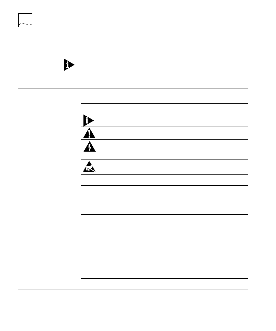
These tables list conventions used throughou t this guide.
Icon Notice Type Description
Information note Information that contains important features or
Caution Information to alert you to potential damage to a
Warning Information to alert you to potential personal injury
ESD Information to alert you to take proper grounding
Convention Description
Text represented as a
screen display
Text represented as
commands
Text represented as
menu
names
sub-menu
or
.
This typeface
terminal screen, for example:
Netlogin:
This typeface
example:
setenv TCMHOME directory
This guide always gives the full form of a command in
uppercase and lowercase letters. However, you can
abbreviate comm an ds by e nte ring only the uppercase lette rs
and the appropriate value. Commands are not case-sensitive.
This typeface
within procedures, for example:
On the
instructions.
program, system, or device.
or fatality. May also alert you to potential electrical
hazard.
precautions before handling a product.
represents displays that appear on your
represents commands that you enter for
represents all menu and sub-menu names
File
menu, click
New
.
Product Description
The Dual E3 Asynchronous Transfer Mode (ATM) Network Interface Card
(NIC) works in conjunction with firmware running on the HiPer Access
Page 8

Product Compatibility
1-3
Router Card (HiPer ARC) to provide a high speed ATM output pipe from
the 3Com Total Control Enterprise Network Hub.
Product
Compatibility
Features
The ATM NIC supports:
■
Dual E3 interfaces for cascading multiple chassis
■
Single auto-sensing 10/100Base-TX Ethernet interface
■
Various standards for routing local area network (LAN) traffic
over an ATM network including:
■
RFC-1483—Multiprotocol en capsulation
■
RFC-1577—Classical IP and ARP
■
Configuration via the HiPer ARC’s command line interface (CLI)
The Dual E3 ATM NIC is compatible with the HiPer ARC Network
Application Card (NAC).
Page 9

2
NSTALLATION
I
This chapter contains Dual E3 Asynchronous Transfer Mode (ATM)
Network Interface Card (NIC) installation information.
Installat ion Tools
Installation Procedure
To install this NIC in the Total Control chassis, you need a #2 Phillips and
flat-head screwdriver.
To install this NIC:
To reduce the risk of electrostatic discharge (ESD), take proper
ESD:
grounding precautions before handling the NIC.
Install the NIC with or without power applied to the chassis.
1
Select a slot at the rear of the Total Control chassis for installing the NIC.
Install this NIC in slots: 1–17
CAUTION:
Router Card (ARC) Network Application Card (NAC).
The Dual E3 A TM NI C must be in stalled behind a Hi Per Access
Page 10

2-2
HAPTER
C
NSTALLATION
2: I
For managed chassis, slot 17 is reserved for a NIC corresponding to the
Network Management C ard (NMC).
2
Use a #2 Phillips screwdriver to remove the safety panel covering
this slot.
Page 11

Installation Procedure
3
Insert the NIC between the slot’s upper and lower card guides.
2-3
4
Slide the NIC into the chassis, until the front of the NIC is flush with the
chassis.
Page 12

2-4
HAPTER
C
NSTALLATION
2: I
5
Use a flat-head screwdriver to tighten the screws on the front panel.
6
Cover any unused chassis slots with safety panels.
7
Install the HiPer ARC NAC. Refer to the
Guide
for more information.
HiPer ARC NAC Getting Started
Page 13

ETWORK INTERFACE
N
C
ARD
3
Physical Interfaces
ABLING
C
This chapter provides information about the physical interfaces of the
Dual E3 Asynchronous Transfer Mode (ATM) Network Interface Card
(NIC), instructions for accessing the corresponding Ne twork Application
Card (NAC) through the command line in terface (CLI), and option s for
cabling the E3 port.
The Dual E3 ATM NIC has the following physical interfaces:
Callout Interface Description
HiPer
ATM NIC
E3
CONSOLE
LINE A
LINE B
10/100 Base-T
ETHERNET
1
1
TX
RX
TX
RX
2
2
3
3
4
5
4
5
6
6
Console:
RJ-45 RS-232-C port configured as DTE.
■
Connect to this port to access the
HiPer ARC NAC’s CLI. This port is
configured for 8 data bits, 1 stop bi t,
no parity. This port’s baud rate is
selectable via DIP swi tch settings on
the HiPer ARC NAC.
Span A TX:
BNC E3 transmit port for Span A.
Span A RX:
BNC E3 receive port for Span A.
Span B TX:
BNC E3 transmit port for Span B.
Span B RX:
BNC E3 receive port for Span B.
10/100 Mbps Ethernet:
RJ-45 Ethernet port.
■
This port auto-senses Ethernet
10Base-T or 100Base-TX networks.
Page 14

3-2
HAPTER
C
ETWORK INTERFACE CARD CABLING
3: N
Accessing the Command Line Interface
To access the CLI of the corresponding NAC, connect the following cables
to the NIC’s console port.
HiPer
ATM NI C
E3
CONSOLE
LINE A
TX
RX
LINE B
TX
RX
10/100 Base- T
ETHERNET
Callout Description
1 RJ-45 connector to NIC’s console port
2 DB-25 male connector to modem for remote operations
3 DB-25 female-to-female null modem adapter to PC or terminal
COM port
E3 Port Cabling Options
Cabling a Single ATM
Network Interface
Card
Cable the ATM NIC’s E3 span ports for an independent connection
between a single chassis and the ATM switch, or for multiple cascaded
chassis with a single connection to the switch .
The Span B port must be used for casc ading mul tiple chassis. It cann ot be
used as an independent connection to an ATM switch.
To cable a single chassis to an ATM switch, connect the A TM switch to the
ATM NIC’s Span A port. Refer to the
Dual E3 ATM NIC Product Reference
for configuration information.
Page 15

E3 Port Cabling Options
3-3
Cabling Multiple
Cascaded ATM
Network Interface
Cards
Cascade or daisy-chain multiple ATM NICs to provide additional modem
ports and reduce the number of connections to the ATM switch. This
configuration allows multiple NICs in the same chassis or multiple chassis.
Cascading Multiple NICs in the Same Chassis
Callout Description
1 ATM switch
2 ATM NIC 1
3 ATM NIC 2
4 Connection from switch’s TX to SPAN A’s RX of NIC 1
5 Connection from switch’s RX to SPAN A’s TX of NIC 1
6 Connection from Span B’s TX of NIC 1 to SPAN A’s RX of NIC 2
7 Connection from Span B’s RX of NIC 1 to SPAN A’s TX of NIC 2
Page 16

3-4
HAPTER
C
ETWORK INTERFACE CARD CABLING
3: N
Cascading Single NIC’s in a Different Chassis
Callout Description
1 ATM switch
2 Chassis 1
3 Chassis 1’s ATM NIC
4 Connection from switch’s TX to Span A’s RX of Chassis 1’s NIC
5 Connection from switch’s RX to Span A’s TX of Chassis 1’s NIC
6 Connection from Span B’s TX of Chassis 1’s NIC to SPAN A’s RX of
Chassis 2’s NIC
7 Connection from Span B’s RX of Chassis 1’s NIC to SPAN A’s TX
Chassis 2’s NIC
8 Chassis 2
9 Chassis 2’s ATM NIC
Page 17

E3 Port Cabling Options
Cascading Multiple NIC’s in a Different Chassis
3-5
Callout Description
1 ATM switch
2 Chassis 1
3 Chassis 1’s ATM NIC 1
4 Chassis 1’s ATM NIC 2
5 Connection from switch’s TX to Span A’s RX of Chassis 1’s NIC 1
6 Connection from switch’s RX to Span A’s TX of Chassis 1’s NIC 1
7 Connection from Spa n B’ s TX of Cha ssis 1’ s NIC 1 to S PAN A’s RX of
8 Connection from Spa n B’ s RX o f Cha ssis 1’s NI C 1 to S PAN A’s TX of
9 Connection from Spa n B’ s TX of Cha ssis 1’ s NIC 2 to S PAN A’s RX of
10 Connection from Span B’s RX of Chassis 1’s NIC 2 to SPAN A’s TX
(continued)
Chassis 1’s NIC 2
Chassis 1’s NIC 2
Chassis 2’s NIC 1
Chassis 2’s NIC 1
Page 18

3-6
HAPTER
C
ETWORK INTERFACE CARD CABLING
3: N
Callout Description
11 Chassis 2
12 Chassis 2’s ATM NIC 1
13 Chassis 2’s ATM NIC 2
14 Connection from Span B’s TX of Chassis 2’ s NIC 1 to SPAN A’s RX of
15 Connection from Span B’s RX of Cha ssis 2’s NI C 1 to S PAN A’s TX of
Chassis 2’s NIC 2
Chassis 2’s NIC 2
Page 19

A
Certification
ECHNICAL
T
EMI/RFI
■
S
EN55022 A
PECIFICATIONS
Regulatory
Compliance
Statements
Safety
United States
FCC Part 15 Compliance Statement
This equipment has been tested and found to comply wit h the limits for a
Class A digital device, pursuant to Part 15 of the FCC Rules. These limits
are designed to p rovide reasonable protecti on against harmful
interference when the equipment is operat ed in a commercial
environment. This equipment generates, uses, and can radiate radio
frequency ener gy and, if not installed and used in accordance wi th the
instruction manual, may cause harmful interference to radio
communications. Operat ion of this equip ment in a r esidential ar ea is likel y
to cause harmful interference in which case the user will be required to
correct the interference at his own expense.
■
EN 60950
Page 20

A-2
PPENDIX
A
A: T
Interface Specifications
Console Port
Line A and Line B E3
Ports
ECHNICAL SPECIFICATIONS
Electrical Specification:
Connector:
Configuration:
Transmission Method:
Transmission Rate:
Electrical Specification:
Connectors:
Transmission Media:
Timing Source:
Framing:
Line Coding:
RS-232-C (EIA/TIA-232-E standard)
RJ-45, 8 position modular jack
Data Terminal Equipment (DTE)
Unbalanced RS-232
38,400 bps maximum
E3 interface
BNC coaxial connectors; one transmit (T X) and
one receive (RX)
75 ohm (nominal impedance) coaxial cable
User selectable between:
■
Internal
■
Network
■
ATM Direct Mapping (ADM)
■
Physical Layer Convergence Protocol (PLCP)
High Density Bipolar 3 Zeroes (HDB3)
Page 21

Ethernet
10Base-T/100Base-TX
Ports
Data Transfer Rate:
Connector:
Accessing Scheme:
Topology:
Maximum Nodes:
Transmission
Medium:
Network Lobe
Distance:
Current Draw
10/100 Mbps Auto-Negotiated
8-position modular jack, Stewart 88-360808 or equivalent
Carrier Sense Multiple Access with Collision Detection
(CSMA/CD)
Star-wired hub using multiport repeater
Limited only by repeate r
Unshielded Twisted Pair (UTP) Category 3 or Category 5 for
10Base-T applications, Category 5 for 100Base-TX
100 m (328 ft) suggested m aximum. L onger cablin g can be
used at the expense of reduced receiver squelch levels.
A-3
Current Draw
Environment
Shipping and Storage
Operating
Physical Dimensions
+5.2 vDC @ 500 mA typical maximum
Typical maximum refers to the maximum current draw under most typical
configurations.
Temperature:
Relative Humidity:
Temperature:
Relative Humidity:
Inches Centimeters
Length:
Width:
Height:
5.30 13.46
0.79 2.00
6.90 17.53
-25 to 75° C, -13 to 167° F
0 to 100%, Non-condensing
0 to 40° C, 32 to 104° F
0 to 95%, Non-condensing
Page 22

3Com Corporation
5400 Bayfront Plaza
P.O. Box 58145
Santa Clara, CA
95052-8145
©1999
3Com Corporation
All rights reserved
Printed in the U.S.A.
Part No. 1.024.1334-00
 Loading...