

Page 1

Dual 56K LAN Modem
User Guide
MODEL NO.
3C888
Part No. 1.018.1752
Published May 2000
http://www.3com.com/
http://www.3com.com/
Page 2

3Com Corporation
5400 Bayfront Plaza
Santa Clara, California
95052-8145
Copyright © 3Com Corporation, 2000. All rights reserved. No part of this documentation may be
reproduced in any form or by any means or used to make any derivative work (such as translation,
transformation, or adaptation) without permission from 3Com Corporation.
3Com Corporation reserves the right to revise this documentation and to make changes in content from
time to time without obligation on the part of 3Com Corporation to provide notification of such revision or
change.
3Com Corporation provides this documentation without warranty of any kind, either implied or expressed,
including, but not limited to, the implied warranties of merchantability and fitness for a particular purpose.
3Com may make improvements or changes in the product(s) and/or the program(s) described in this
documentation at any time.
UNITED STATES GOVERNMENT LEGENDS:
If you are a United States government agency, then this documentation and the software described herein
are provided to you subject to the following restricted rights:
For units of the Department of Defense:
Restricted Rights Legend: Use, duplication, or disclosure by the Government is subject to restrictions as set
forth in subparagraph (c) (1) (ii) for Restricted Rights in Technical Data and Computer Software Clause at 48
C.F.R. 52.227-7013. 3Com Corporation, 5400 Bayfront Plaza, Santa Clara, California 95052-8145.
For civilian agencies:
Restricted Rights Legend: Use, reproduction, or disclosure is subject to restrictions set forth in subparagraph
(a) through (d) of the Commercial Computer Software - Restricted Rights Clause at 48 C.F.R. 52.227-19 and
the limitations set forth in 3Com Corporation’s standard commercial agreement for the software.
Unpublished rights reserved under the copyright laws of the United States.
Unless otherwise indicated, 3Com registered trademarks are registered in the United States and may or may
not be registered in other countries.
3Com, OfficeConnect, and U.S. Robotics are registered trademarks of 3Com Corporation. 3ComFacts is a
service mark of 3Com.
Acrobat and Adobe are registered trademarks of Adobe Systems, Incorporated. America Online is a
registered trademark of America Online, Inc. Macintosh is a registered trademark of Apple Computer.
Compuserve is a registered trademark of Compuserve Interactive Services, Inc. LZS is a registered trademarks
of hi/fn, Inc. Pentium is a registered trademark of Intel Corporation. IBM is a trademark of International
Business Machines Corporation. Windows and Windows NT are registered trademarks of Microsoft
Corporation. Netscape Navigator is a registered trademark of Netscape Communications. IPX is a registered
trademark of Novell, Inc. UL is a trademark of Underwriters Laboratory, Inc.
Other brand and product names may be registered trademarks or trademarks of their respective holders.
Guide written by Eric Heller.
Page 3

Important Safety Information
I
MPORTANT
WARNING: Warnings contain directions that you must follow for your personal safety. Follow all
instructions carefully.
Please read the following information carefully and thoroughly before installing the unit:
Take exceptional care during the installation and removal of the unit.
■
Locate the unit close to the mains socket outlet, and ensure that the mains socket is accessible.
■
Use the power adapter supplied with the unit to ensure compliance with national and
■
international safety standards. If there is no power adapter supplied, the mains cordset used must
be compliant with the local and national regulations of the target country and must not violate
the safety approval of the product (refer to the Approvals section at the back of this manual).
Disconnect the power adapter before moving the unit. Power can only be disconnected from the
■
unit by removing the power adapter from the unit or from the socket outlet.
Only connect apparatus complying with the relevant interface requirements to the ports on this
■
unit. The safety status of the ports on this equipment are as follows.
■
Ports identified by the labels LAN and Phone = SELV.
SELV (Safety Extra Low Voltage) is a secondary circuit which is designed and protected so that
under normal and single-fault conditions, the voltage between any two accessible parts does
not exceed a safe value (42.2 V peak or 60 V DC).
There are no user-replaceable fuses or user-serviceable parts inside the unit. If there is a physical
■
problem with the unit that cannot be solved with problem solving actions in this guide, contact
the 3Com reseller from whom the equipment was purchased.
If the units are stackable, only stack similar units.
■
S
AFETY
I
NFORMATION
Wichtige Sicherheits-Informatio nen
WARNING: Twisted Pair RJ45 data ports. These are shielded RJ45 data sockets. They cannot be
used as telephone sockets. Only connect RJ45 data connectors to these ports.
WARNUNG: Warnungen enthalten Anweisungen, die Sie zu Ihrer persönlichen Sicherheit befolgen
müssen. Bitte halten Sie sich daran.
Bitte lesen Sie die folgenden Informationen aufmerksam, ehe Sie die Einheit installieren:
Lassen Sie bei Installation und Abbau besondere Vorsicht walten.
■
Stellen Sie die Einheit in der Nähe einer Stromquelle auf und achten Sie darauf, daß diese
■
zugänglich ist.
Verwenden Sie immer den mitgelieferten Netzadapter, damit die Einhaltung nationaler und
■
internationaler Sicherheitsnormen gewährleistet ist. Wurde kein Adapter mitgeliefert, muß das
verwendete Netzkabel den lokalen und nationalen Bestimmungen des Landes entsprechen und
darf die Sicherheitsbestimmungen des Produkts (siehe den entsprechenden Abschnitt am Ende
dieses Handbuchs) nicht verletzen.
Trennen Sie den Netzadapter von der Stromversorgung, bevor Sie die Einheit bewegen. Die
■
Einheit kann nur von der Stromversorgung getrennt werden, indem Sie die Verbindung des
Netzadapters entweder von Einheit oder der Stromquelle trennen.
Schließen Sie nur Geräte an den Schnittstellen dieser Einheit an, die den
■
Interface-Voraussetzungen entsprechen. Die Sicherheitsmerkmale der Schnittstellen dieses Geräts
sind:
■
Schnittstellen mit der Bezeichnung LAN und Phone = SELV. SELV (Safety Extra Low Voltage) ist
ein sekundärer Schaltkreis, der unter normalen und Single-Fault-Bedingungen so eingerichtet
Page 4

ist, daß die Spannung zwischen zwei zugänglichen Bauteilen einen Sicherheitswert nicht
übersteigt (42,2 V Spitzenspannung bzw. 60 V Gleichspannung).
Die Einheit enthält keine Sicherungen oder sonstige Bauteile, die vom Benutzer ausgewechselt
■
oder gewartet werden können. Sollte ein physikalischer Fehler auftreten, der mit den in diesem
Handbuch beschriebenen Maßnahmen nicht zu beheben ist, setzen Sie sich mit dem
3Com-Vertreter in Verbindung, bei dem Sie das Gerät erworben haben.
■
Bei stapelfähiger Konstruktion nur gleichartige Einheiten verwenden.
WARNUNG: Twisted Pair RJ45-Datenschnittstellen. Dies sind abgeschirmte RJ45-Schnittstellen,
die nicht für Telefonsignale verwendet werden können. Schließen Sie an diesen Schnittstellen nur
RJ45-Datenstecker an.
Important Notice de Securite
AVERTISSEMENT: les avertissements présentent des instructions que vous devez suivre très
attentivement pour votre sécurité personnelle.
Veuillez lire les informations suivantes attentivement avant l'installation de l'appareil.
Soyez très prudents pendant toute la durée de l'installation et du déplacement de l'appareil.
■
Placez l'appareil près d'une prise murale qui doit rester accessible à tout instant.
■
■
Utilisez l'adaptateur électrique fourni avec l'appareil pour garantir la conformité totale aux
normes de sécurité nationales et internationales. Si aucun adaptateur n'est fourni, le câble
électrique utilisé doit être conforme aux normes locales et nationales du pays et ne doit en aucun
cas contrevenir aux normes de sécurité d'utilisation de l'appareil (veuillez consulter la section
Approvals (Agréments) au dos du présent manuel).
■
Déconnectez l'adaptateur électrique avant de déplacer l'appareil. L'alimentation ne peut être
déconnectée de l'appareil qu'en retirant l'adaptateur de l'appareil ou de la prise de courant.
■
Ne connectez l'appareil qu'en conformité avec les exigences techniques des ports de connexion
de l'appareil. Les normes de sécurité de chaque port sont les suivantes :
■
Les ports identifiés par les étiquettes LAN et Phone = SELV.
Les circuits SELV (Safety Extra Low Voltage, très basse tension de sécurité) sont des circuits
secondaires qui sont conçus et protégés pour qu'en conditions normales et à défaillance
unique, la tension n'excède jamais la valeur de sécurité de 42,2 V en crête, ou 60 V DC.
■
L'appareil ne contient aucun fusible remplaçable par l'utilisateur ni aucune pièce dont la
maintenance peut être effectuée par l'utilisateur. Si un problème physique survient dans
l'appareil, qui ne peut être résolu au moyen des techniques de dépannage du présent manuel,
contactez le revendeur 3Com qui vous a fourni l'appareil.
■
Si vous disposez de plusieurs appareils empilables sur racks, n'empilez que les appareils similaires.
AVERTISSEMENT: ports de données RJ45 à paires torsadées. Il s'agit de prises de données RJ45
blindées. Elles ne peuvent être utilisées comme prises de téléphone. Elles ne doivent recevoir que les
connecteurs de données RJ45.
Medidas de Seguridad Importantes
ADVERTENCIA: las advertencias contienen instrucciones que es preciso seguir al pie de la letra para
evitar daños personales.
Antes de instalar la unidad, lea atentamente la siguiente información.
Tome todas las precauciones necesarias a la hora de instalar o desinstalar la unidad.
■
Coloque la unidad cerca de una toma de corriente de fácil acceso.
■
■
Utilice el adaptador de corriente suministrado con la unidad, de este modo se asegura el pleno
cumplimiento de las normas de seguridad nacionales e internacionales. En caso de no recibir un
adaptador con la unidad, deberá utilizar un cable que responda a los requisitos estipulados por la
normativa local o nacional pertinente y que no contravenga la garantía de seguridad del producto
(consulte la sección relativa a este punto al final de esta guía).
■
Desenchufe el adaptador antes de mover la unidad. La única forma de interrumpir el paso de
corriente consiste en desenchufar el adaptador de la unidad o de la toma de corriente.
■
No deben conectarse a los puertos de la unidad aparatos que no cumplan los requisitos de la
interfaz en uso. Los puertos de la unidad son de los siguientes tipos:
Page 5

■
Puertos con etiqueta LAN o Phone= SELV.
SELV (Safety Extra Low Voltage) es un circuito secundario diseñado para que el voltaje entre
dos puntos accesibles no exceda límites seguros (42,2 V punta ó 60 V CC) en circunstancias
normales o de fallo simple.
La unidad no contiene fusibles ni otros componentes que el usuario pueda cambiar o reparar. De
■
producirse problemas cuya resolución no se explique en esta guía, póngase en contacto con el
proveedor de 3Com.
Si las unidades que posee son apilables, acople las que sean similares entre sí.
■
ADVERTENCIA: puertos de datos de par trenzado RJ45. Son enchufes blindados RJ45 a los que
sólo deben acoplarse conectores de datos RJ45. No pueden utilizarse como enchufes telefónicos.
Informazioni Importanti per la Sicurezza
AVVERTENZA: il testo delle avvertenze riporta importanti istruzioni alle quali occorre attenersi per
motivi di sicurezza. Seguire attentamente tutte le istruzioni.
Prima di installare l'unità, leggere attentamente le informazioni riportate di seguito.
■
Procedere con estrema cautela durante l'installazione e la rimozione dell'unità.
■
Collocare l'unità vicino a una presa di corrente e verificare che la presa sia accessibile.
Per garantire la conformità alle norme di sicurezza nazionali e internazionali, usare l'adattatore di
■
corrente fornito con l'unità. Se l'adattatore non è compreso, il cavo alimentatore deve essere
conforme alle norme locali e nazionali del paese di destinazione nonché all'omologazione di
sicurezza del prodotto (per ulteriori informazioni consultare la sezione relativa alle omologazioni
riportata alla fine del manuale).
■
Scollegare l'adattatore prima di spostare l'unità. Per scollegare l'unità occorre rimuovere
l'adattatore dall'unità stessa o dalla presa di corrente.
■
Collegare alle porte dell'unità solamente apparecchi conformi ai requisiti della relativa interfaccia.
Le specifiche riguardanti la sicurezza delle porte sono le seguenti:
■
Porte contrassegnate dalle targhette LAN e Phone = SELV. SELV (Safety Extra Low Voltage) è
un circuito secondario ideato e protetto in modo tale che, in condizioni normali e in caso di
un unico guasto, la tensione tra due parti accessibili qualsiasi non superi il valore di sicurezza
(42,2 V picco o 60 V CC).
■
All'interno dell'unità non vi sono fusibili sostituibili dall'utente o parti la cui manutenzione può
essere effettuata dall'utente. Se si verifica un problema che non si è in grado di risolvere
seguendo le istruzioni per la risoluzione dei problemi riportate nel presente manuale, contattare il
rivenditore 3Com presso il quale si è acquistata l'unità.
■
Se le unità sono impilabili, impilare solamente unità simili.
AVVERTENZA: porte dati RJ45 per doppino intrecciato. Si tratta di prese dati RJ45 schermate e
non possono essere utilizzate come prese telefoniche. Collegare solamente connettori dati RJ45 a
queste porte.
Additional Safety Information
■
Only connect apparatus complying with the relevant interface requirements to the ports on
this unit.
■
Disconnect the power adapter before moving the unit.
Retain this user’s guide for later use and pass it on in the event of change of ownership of
■
the unit.
■
Protect the unit from sudden, transient increases and decreases in electrical power by fitting
an in-line surge suppressor or uninterruptible power supply. Products manufactured by us
are safe and without risk provided they are installed, used and maintained in good working
order in accordance with our instructions and recommendations.
■
If any of the following conditions occur, isolate the electricity supply and refer to your 3Com
reseller.
If the case or cover is not correctly fitted or if it is damaged.
■
If the unit begins to make an odd noise, smell or smoke.
■
Page 6

■
If the unit shows signs of a distinct change in performance.
Never install telephone wires during a lightning storm, or install telephone connection
■
sockets in wet locations, unless the socket is specifically designed for wet locations.
Do not touch uninstalled telephone wires or terminals unless the telephone line has been
■
disconnected at the network interface. Always exercise caution when installing or modifying
telephone lines.
Do not use a telephone, which is connected to the unit, to report a gas leak in the vicinity of
■
the leak.
Do not spill food or liquids on the unit. If the unit gets wet, isolate the electrical supply and
■
contact your 3Com reseller.
■
Do not push any objects into the openings of the unit. Doing so can cause fire or electric
shock by shorting out internal components.
Only equipment approved for use by your telecom company can be connected to the
■
telephone port.
■
Avoid using a telephone, which is connected to the unit (other than a cordless type), during
an electrical storm.
■
Equipment connected to the telephone port must be located in the same building as the
unit.
■
Be sure nothing rests on the units system cables and that the cables are not located where
they can be stepped on and cause damage to the unit.
■
Keep the unit away from radiators and heat sources. Allow 25mm (1inch) around the unit to
provide adequate air circulation.
■
Install the unit in a clean area that is free from dust or extreme temperatures.
■
Allow a clearance gap of at least a 150 mm (6 inches) from the rear panel of the unit, to
allow for cable access.
Interconnecting directly, or by way of other apparatus, to ports complying with SELV
■
requirements may produce hazardous conditions on the network. Advice should be sought
from a competent engineer before such a connection is made.
Page 7

T
ABLE
MPORTANT
I
Wichtige Sicherheits-Informationen 3
Important Notice de Securite 4
Medidas de Seguridad Importantes 4
Informazioni Importanti per la Sicurezza 5
Additional Safety Information 5
BOUT
A
Introduction 11
How to Use This Guide 11
Conventions 12
Year 2000 Compliance 12
T
HIS
OF
S
G
C
AFETY
UIDE
ONTENTS
NFORMATION
I
3
NTRODUCTION
I
Introduction 13
Applications 14
Hardware Description 16
Features 18
UAL
D
56K LAN M
F
UNCTIONALITY
LAN Side Connectivity: Installing an Ethernet Hub 21
Wan Side: The Two 56K Modems 22
Using the Modem Channels 22
Dial-in Functionality 25
Understanding Multilink PPP and Other Line Usage Options 27
The Virtual FAX Modem (Windows 95, 98, NT, and 2000) 28
Support for Virtual Private Networks (VPNs) 29
B
EFORE
Package Contents 31
Before You Begin 31
Why Check TCP/IP and IP Address Settings? 32
Checking TCP/IP and IP Address Settings 32
Adding TCP/IP to Your Protocols List 34
Y
OU
B
ODEM
D
ESCRIPTION
EGIN
Page 8

Setting Up Your Computer If You Have a Static IP Address 39
INSTALLING THE DUAL 56K LAN MODEM
Before You Start the Installation 43
CONFIGURING THE DUAL 56K LAN MODEM FOR INTERNET ACCESS
Typical Configuration 47
Changing the LAN Modem IP Address for Static IP Users 52
The LAN Modem Main Configuration Page 53
Connecting an External Hub to the Dual 56K LAN Modem 56
CONFIGURING THE DUAL 56K LAN MODEM FOR PRIVATE NETWORK
A
CCESS
Before You Start the Configuration 59
Configuration Steps 60
Changing the LAN Modem IP Address for Static IP Users 67
The LAN Modem Main Configuration Page 68
The LAN Modem Support Web Site 70
ADVANCED CONFIGURATION
Advanced Configuration 71
Configuring Additional Service Providers 71
Editing Service Provider Profiles 76
Associating Service Providers with Workstations on the LAN 76
Using a Connection Script 77
Configuring LAN Parameters 81
Configuring V.90 Modem Control Parameters 83
Changing Data Call Parameters 85
Specifying a WINS Server Address 87
Configuring the Local DNS Table 88
Reserving DHCP Addresses 89
Changing Your Password 89
Locking and Unlocking the Configuration 90
Using Selective Password Protection 91
Configuring the LAN Modem from a Remote Location 91
Checking for Dual 56K LAN Modem upgrades 94
CONFIGURING THE DUAL 56K LAN MODEM FOR DIAL-IN SUPPORT
Understanding Dial-in Basics 95
Understanding the Three Dial-in Profile Types 96
Part I. Configuring the Server-side Dual 56K LAN Modem for Dial-in Support 99
Part II. Configuring a Client Device for Dial-out Access 109
Configuring Dial-in User Parameters 114
Page 9

Placing a Call from a Client-side LAN Modem 118
PLACING, RECEIVING AND DISCONNECTING CALLS
Using the LAN Modem Desktop Manager (Windows only) 119
Placing Calls 119
Receiving Calls 121
Disconnecting Calls 122
TROUBLESHOOTING AND MAINTENANCE
Checking the Basics 125
Monitoring LEDs 125
Evaluating Symptoms and Solutions 126
Finding More Information 131
Contacting Technical Support 131
Downloading Firmware to Your Dual 56K LAN Modem 131
Resetting the Dual 56K LAN Modem 131
Reviewing Statistics 132
Synchronizing the LAN Modem Clock 134
NETWORKING PRIMER
What is a network? 137
INSTALLING AND USING THE VIRTUAL FAX MODEM
Installing the Virtual FAX Modem 147
CREATING A VIRTUAL PRIVATE NETWORK (VPN) TUNNEL
Creating a Virtual Private Network (VPN) Tunnel 151
FACTORY DEFAULTS
Dual 56K LAN Modem Factory Defaults 153
SPECIFICATIONS
Specifications 155
Year 2000 Compliance 155
Page 10

GLOSSARY
3COM CORPORATION LIMITED LIFETIME WARRANTY
REGULATORY AND APROVAL INFORMATION
Page 11

ABOUT THIS GUIDE
About This Guide provides an overview of this User Guide, describes guide
conventions, and shows you where to look for specific information.
Introduction This guide tells you how to install and configure the Dual 56K LAN Modem and
provides descriptions of key applications and networking concepts.
Audience Description This guide is intended for end users with no presumed level of expertise.
How to Use
This Guide
Table 1 shows you where to find specific information in this guide.
Table 1 Specific Information
If you are looking for... Turn to...
An overview of the Dual 56K LAN Modem Chapter 1
A description of the Dual 56K LAN Modem hardware components Chapter 1
An explanation of the Dual 56K LAN Modem’s key functionality Chapter 2
Instructions on checking TCP/IP and IP address settings Chapter 3
Instructions on installing the Dual 56K LAN Modem Chapter 4
Instructions on configuring the Dual 56K LAN Modem for Internet access Chapter 5
Instructions on configuring the Dual 56K LAN Modem for private network access Chapter 6
Instructions on advanced configuration of the Dual 56K LAN Modem Chapter 7
Instructions on configuring the Dual 56K LAN Modem for dial-in support Chapter 8
Information on placing and disconnecting calls and using the Desktop Manager Chapter 9
Information on troubleshooting and maintenance Chapter 10
Background information on networking Appendix A
Information on installing and using the Virtual FAX Modem application Appendix B
Information on creating a virtual private network (VPN) tunnel Appendix C
Dual 56K LAN Modem factory default settings Appendix D
Technical specifications for the Dual 56K LAN Modem Appendix E
Glossary definitions for terms used in this guide Glossary
Page 12
12 ABOUT THIS GUIDE
Conventions Table 2 and Table 3 list conventions that are used throughout this guide.
Table 2 Notice Icons
Icon Notice Type Alerts you to...
Information note Important features or instructions
Caution Risk of personal safety, system damage, or loss of data
Warning Risk of severe personal injury
Table 3 Text Conventions
Convention Description
Commands The word “command” means you must enter the command exactly as
The words “enter”
and “type”
[Key] names Key names appear in text in one of two ways:
Menu commands
and buttons
Words in italicized
type
Words in bold-face
type
shown in text and press the Return or Enter key. Example:
To remove the IP address, enter the following command:
SETDefault!0 -IP NETaddr = 0.0.0.0
NOTE: This guide always gives the full form of a command in
uppercase and lowercase letters. However, you can abbreviate
commands by entering only the uppercase letters and the appropriate
value. Commands are not case-sensitive.
When you see the word “enter” in this guide, you must type
something and then press the Return or Enter key. Do not press the
Return or Enter key when an instruction simply says “type.”
■ Referred to by their labels, such as “the Return key” or “the Escape
key”
■ Written with brackets, such as [Return] or [Esc].
If you must press two or more keys simultaneously, the key names are
linked with a plus sign (+). Example:
Press [Ctrl]+[Alt]+[Del].
Menu commands or button names appear in italics. Example:
From the Help menu, select Contents.
Italics emphasize a point or denote new terms at the place where they
are defined in the text.
Bold text denotes key features.
Year 2000 Compliance The OfficeConnect LAN Modem is Year 2000 compliant. Specifically, its system
clock is capable of accepting and storing dates including and beyond the year
2000. For information on Year 2000 compliance and 3Com products, visit the
3Com Year 2000 web page:
http://www.3com.com/products/yr2000.html.
Page 13

INTRODUCTION
1
This chapter provides an overview of the OfficeConnect® Dual 56K LAN Modem,
referred to throughout this document as the Dual 56K LAN Modem, or simply as
the LAN Modem.
Introduction The Dual 56K LAN Modem is an easy-to-install, Local Area Network (LAN) to Wide
Area Network (WAN), analog IP router. The LAN Modem provides four 10BASE-T
Ethernet ports for LAN-side connections and two internal, V.90 ITU 56K-standard
modems for WAN-side connections, plus two additional analog ports for standard
analog equipment such as a phone and/or fax machine.
To configure the Dual 56K LAN Modem, you use a standard web browser on a
computer attached to the LAN Modem to access the LAN Modem’s web-based
configuration screens. Afterwards, you can attach up to three additional
computers directly to the LAN Modem, or a combination of external hubs and
computers, to create WAN access for up to 25 users.
Dial-in and Dial-out
Access
Dual 56K Analog
Modems
The Dual 56K LAN Modem supports both dial-in and dial-out remote access. This
means that you can use the LAN Modem on either end of a LAN-to-WAN
connection: to call out from your local LAN to an already existing network (such as
the Internet or a private, corporate network), or to receive calls into your LAN from
up to ten previously-defined remote sites. For calls to a private network via the
Internet, where security is a consideration, the LAN Modem also supports
pass-though VPN (Virtual Private Network) tunneling.
The V.90 56K ITU standard used on each of the Dual 56K’s internal modems
provides download speeds of up to 56K
can be accessed independently on a first-come, first-served basis by any
combination of users dialing out from the LAN and users dialing in to the LAN for
separate, 56K connections. Or, the LAN Modem can be configured to provide one
high-speed connection at a time.
The Dual 56K LAN Modem is software upgradeable, allowing for easy upgrades to
new features and enhancements as they become available. Visit the LAN Modem
Web site for the latest firmware releases:
http://www.3com.com/support/docs/lanmodem.
1.Capable of receiving downloads at up to 56 Kbps and sending at up to 31.2 Kbps. Due to FCC regulations, receiving speeds are limited to 53 Kbps. Actual speeds may vary. Requires compatible analog
phone line and server equipment. The Dual 56K LAN Modem complies with the V.90 ITU standard and
is backwards-compatible with all US Robotics 56K standards. Standard officially determined in February,
1998; ratified in September, 1998.
1
for each analog line. The two modems
Page 14
14 CHAPTER 1: INTRODUCTION
Applications The primary applications for the Dual 56K LAN Modem are:
■ Local networking with shared, dial-out access to the Internet
■ Local networking with shared, dial-out access to a private network, such as a
remote corporate office LAN (this can include indirect Internet access through
the private network’s Internet connection)
■ Local networking with shared, simultaneous dial-out access to the Internet and
a private network
■ Combined dial-in and dial-out access for several possible networking scenarios
(refer to Chapter 8 for specific dial-in applications).
The following diagrams illustrate the primary Dual 56K LAN Modem applications:
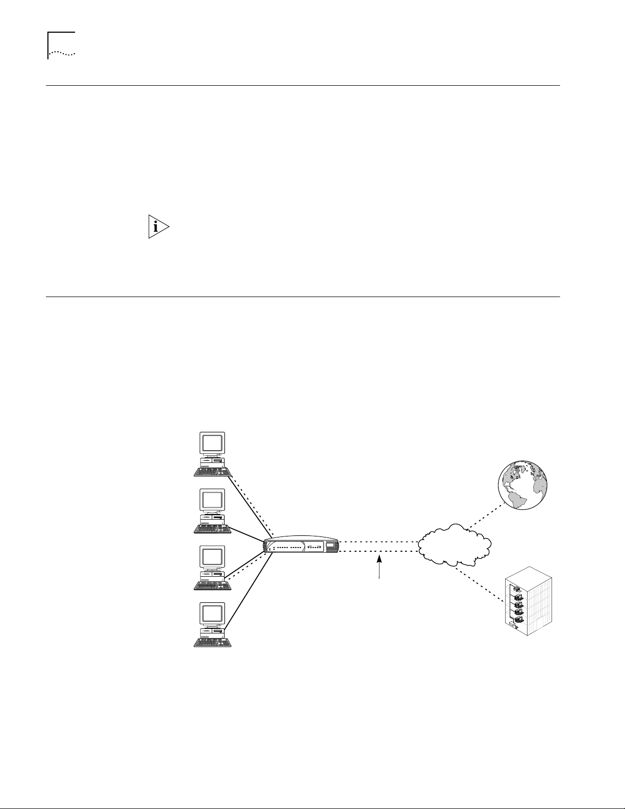
Local Networking with
Shared Internet Access
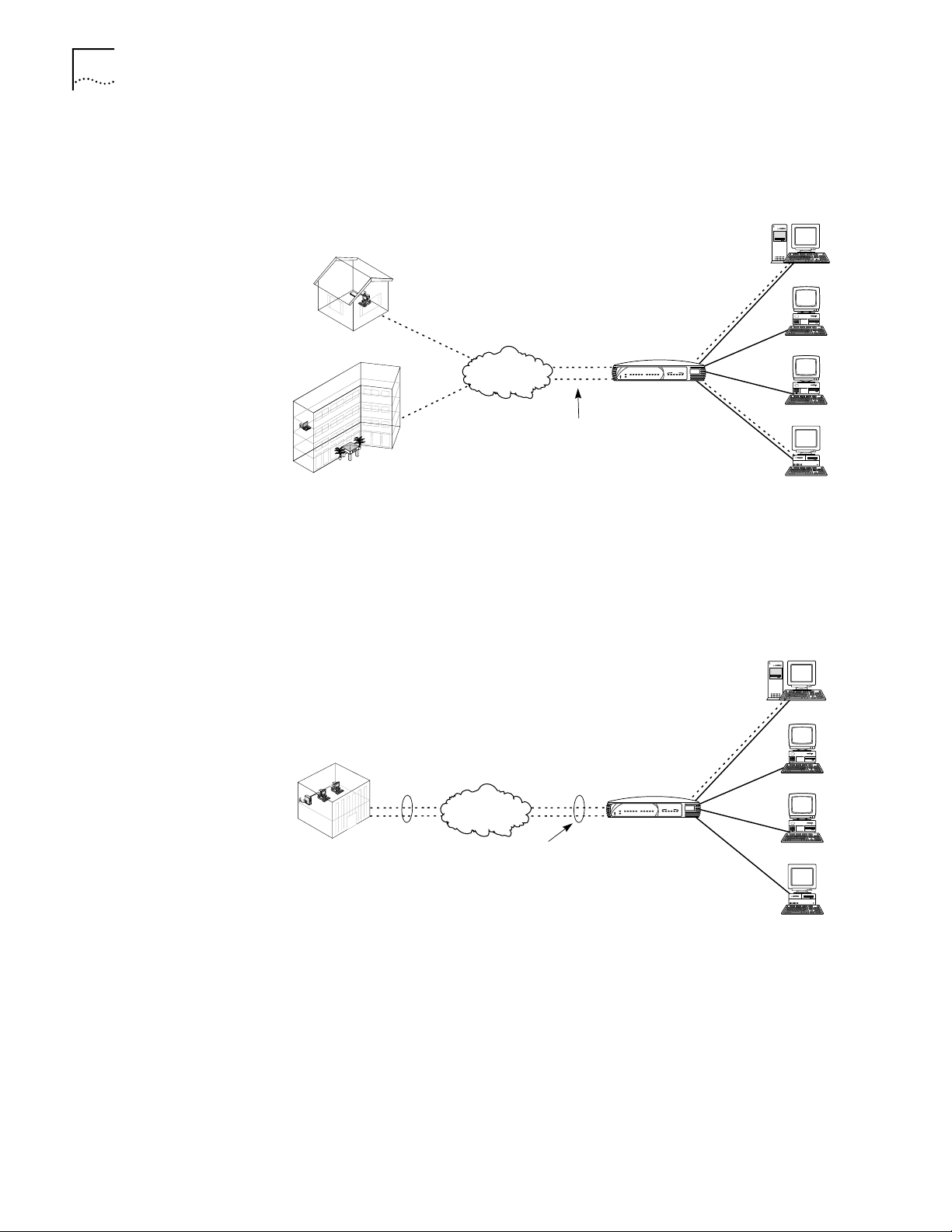
Local Networking with
Shared Private Network
Access
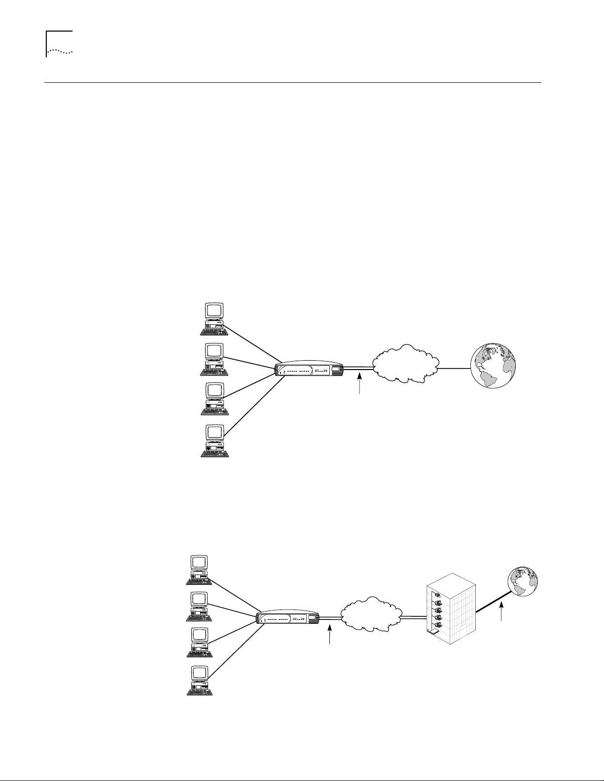
Users can share access to the Internet while they continue to network locally, as
shown in Figure 1.
OfficeConnect
Dual 56K LAN Modem
M
e
s
s
a
g
e
C
A
D
A
P
o
w
e
r
A
l
e
r
t
LAN StatusMODEM 2MODEM 1
3
2
O
O
R
R
1
S
D
D
H
4
S
C
C
A
T
X
O
D
D
D
A
H
L
L
OfficeConnect Dual 56k LAN Modem
Public telephone
network
Internet
Two analog POTs lines
Figure 1 Local Networking with Shared Internet Access
Users can share access to a remote private network, such as a corporate office
LAN, while they continue to network locally. This can include indirect access to the
Internet through the private network’s Internet connection, as shown in Figure 2.
OfficeConnect
Dual 56K LAN Modem
M
e
s
s
a
g
e
P
o
w
e
r
A
l
e
r
t
LAN StatusMODEM 2MODEM 1
A
A
T
C
C
C
R
R
1
S
A
D
D
D
4
S
2
O
O
3
X
A
O
D
D
D
H
H
L
L
OfficeConnect Dual 56k LAN Modem
Two analog POTS lines
Public telephone
network
Private network
Figure 2 Local Networking with Remote Private Network Access
ted
Internet
onnec
c
More
m
o
C
3
m
o
C
3
E
L
O
S
N
O
C
T
E
N
K
C
A
T
S
0
0
5
1
m
e
t
s
y
N
S
A
s
L
s
e
c
c
A
e
t
X
o
R
m
e
R
R
O
E
X
C
P
T
N
U
A
S
K
W
L
K
C
X
r
e
T
A
T
w
o
S
X
P
t
R
e
s
e
R
s
U
u
t
a
N
D
t
D
S
S
I
I
R
B
4
3
4
/
3
D
2
/
1
2
T
O
2
L
1
S
4
G
O
L
A
N
A
3
1
1
T
O
L
S
2
Dedicated or
leased line
connection
Page 15
Applications 15
OfficeConnect
Dual 56K LAN Modem
Public telephone
network
Two analog POTs lines
Dial-in modem user
Server
Workstation
Workstation
Workstation
Internet
or
private network
A
l
e
r
t
P
o
w
e
r
M
e
s
s
a
g
e
R
D
A
A
C
D
S
D
O
H
R
D
A
A
C
D
S
D
O
H
1
T
X
C
O
L
L
2
3
4
OfficeConnect Dual 56k LAN Modem
LAN StatusMODEM 2MODEM 1
Local Networking with
Shared Access to the
Internet and a Private
Network
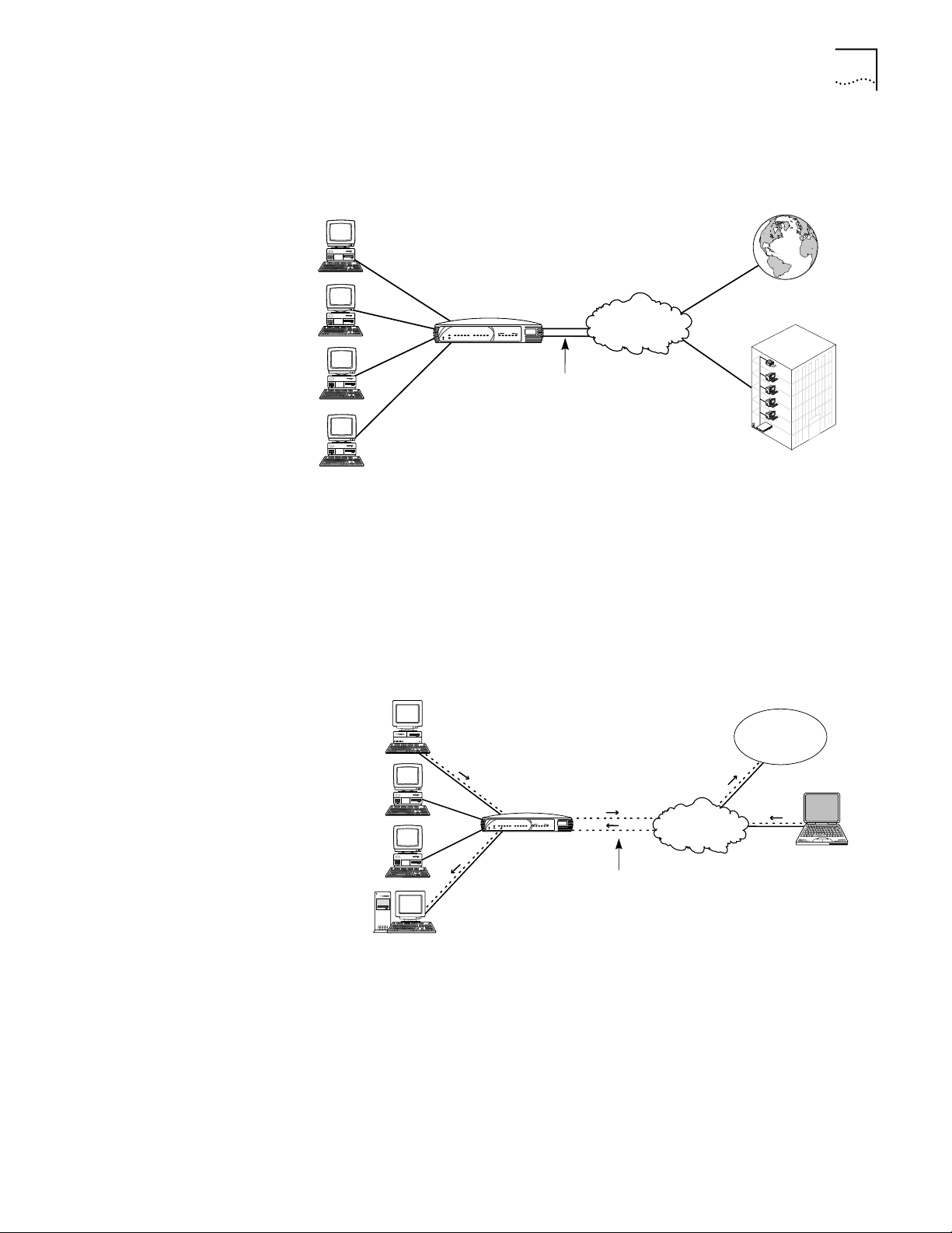
Users can share simultaneous access to both the Internet and a remote private
network while they continue to network locally, as shown in Figure 3.
Internet
OfficeConnect
Dual 56K LAN Modem
M
e
s
s
a
g
e
A
C
A
P
o
w
e
r
A
l
e
r
t
LAN StatusMODEM 2MODEM 1
T
A
C
C
R
R
1
4
S
2
S
D
D
D
3
O
O
X
O
A
D
D
D
H
H
L
L
OfficeConnect Dual 56k LAN Modem
Two analog POTS lines
Figure 3 Local Networking with Shared Access to the Internet and a Remote Private
Network
Public telephone
network
ted
ec
n
n
co
e
r
o
M
m
o
C
3
m
o
C
3
E
L
O
S
N
O
C
T
E
N
K
C
A
T
S
0
0
5
1
m
e
t
s
y
N
S
A
s
L
s
e
c
c
A
e
t
X
o
R
m
e
R
R
O
E
X
C
P
T
N
U
A
S
K
W
L
K
C
X
r
e
T
A
T
w
S
o
X
P
t
R
e
s
e
R
s
U
u
t
a
N
D
t
D
S
S
I
I
R
B
4
3
4
/
3
D
2
/
1
2
T
O
2
L
1
S
4
G
O
L
A
N
A
3
1
1
T
O
L
S
2
Private network
Combined Dial-in and
Dial-out Access
Users can share access to the Internet or a remote private network and continue to
network locally, while a user dials in for access to a server or servers on the LAN, as
shown in Figure 4. (Other dial-in scenarios are possible. Refer to Chapter 8 for
specific applications.)
Figure 4 Local Networking and Dial-out Access with Dial-in Support
Page 16

16 CHAPTER 1: INTRODUCTION
Hardware Description The following is an overview of the Dual 56K LAN Modem hardware, including the
function of the front panel LEDs and back panel connectors.
Front Panel LED
Description
The front panel contains the LEDs illustrated in Figure 5.
M
essage
Alert
SD
CD
AA
Pow
er
OH
RD
AA
SD
CD
OH
RD
Figure 5 Dual 56K LAN Modem Front Panel
LAN StatusMODEM 2MODEM 1
COLL
1
TX
OfficeConnect Dual 56k LAN Modem
4
2
3
The functions of the front panel LEDs are described in Table 4. These front panel
LEDs indicate proper operation and display analog modem and Ethernet port
activity status.
Table 4 Front Panel LED Indicator Definitions
LED Color Description
Alert Amber Operational Status. Lit during power-on self-diagnostic test
Power Green Power Indicator. Remains lit as long as power is supplied to
Message Not implemented.
AA (MODEM 1 or 2) Green Auto Answer. Shows the answer status for Modem 1 or 2,
CD (MODEM 1 or 2) Green Carrier Detect. Remains lit for the indicated modem if the
RD (MODEM 1 or 2) Green Received Data. Flashes when the indicated modem receives
SD (MODEM 1 or 2) Green Send Data. Flashes when the indicated modem sends data to
OH (MODEM 1 or 2) Green Off Hook. Remains lit when the indicated modem has gone
TX Green Ethernet Transmit Status. Flashes green when data is being
or after pressing the reset button.
Off indicates that the unit has passed the diagnostic test and
is working properly.
Flashes if one or more of the diagnostics have failed or after
the unit is placed in firmware download mode and is awaiting
firmware upgrade.
the unit.
as follows:
■ Flashes during an incoming call.
■ Remains lit for the duration of the call.
■ Off when the LAN Modem originates a call.
Dual 56K LAN Modem receives a valid data signal (carrier)
from a remote modem (such as an ISP), indicating that data
transmission is possible.
data from a remote site.
a remote site.
off hook.
transmitted to the Ethernet LAN from the Dual 56K LAN
Modem.
Off indicates that no data is being transmitted to the Ethernet
LAN from the Dual 56K LAN Modem.
Page 17
Hardware Description 17
10-30V DC
2A MAX
RESET
1
3
2
4
LAN
LINE 1 PHONE 1 LINE 2 PHONE 2
Table 4 Front Panel LED Indicator Definitions (continued)
LED Color Description
COLL Amber Ethernet Collision Status. Flashes amber when some
collisions are taking place on the Ethernet LAN.
Off indicates that no collisions are taking place on the
Ethernet LAN.
Ports 1-4 Green Ethernet LAN Port Status. On indicates that the unit
detects the Ethernet link integrity signal from an attached
computer and operation is normal.
Flashes when the LAN Modem receives data on the
associated port.
Off indicates that the unit does not detect the Ethernet link
integrity signal. The Ethernet cable may not be properly
connected or the cable may be the wrong polarity.
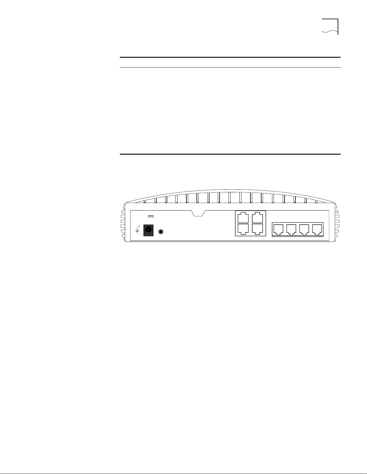
Back Panel Connector
Description
The back panel contains the connectors illustrated in Figure 6.
Figure 6 Dual 56K LAN Modem Back Panel
From left to right, the back panel consists of the following:
■ Power: Connect the power module cable to this port.
■ RESET: Press this button to re-initialize or factory re-set the unit (refer to
Chapter 10 for instructions).
■ LAN 1, 2, 3, and 4: Connect up to four computers (or a combination of
computers and an external hub), to these four 10BASE-T Ethernet ports.
■ LINE 1: Connect one of the provided RJ-11 analog cables from the wall outlet
to this port.
■ PHONE 1: Connect an external analog device, such as a telephone or fax
machine, to this port.
■ LINE 2: Connect the second RJ-11 analog cable from the wall outlet to this
port.
■ PHONE 2: Connect an additional external analog device, such as a telephone
or fax machine, to this port.
Page 18

18 CHAPTER 1: INTRODUCTION
Features Ease of Installation and Use
■ Web-based, point-and-click user interface for easy configuration
■ Automatic Internet configuration verification via your Internet Service Provider
(ISP)
■ Web-based, context-sensitive online help
■ Dial-in Wizard for easy configuration of dial-in setup
■ LAN Modem Desktop Manager tool for easy management and stats
monitoring (Windows 95
■ EZ- LAN Wizard, which optimizes workstation settings for use with the Dual
®
, 98®, NT® and 2000®)
56K LAN Modem (Windows 95, 98, NT and 2000)
High Performance
■ Two internal 56K modems, capable of downloading at speeds of up to 112
■ V.42/MNP 2-4 error control and V.42 bis/MNP 5 data compression
■ Hi/fn™ LZS
1
Kbps
(without compression)
®
compression, which conforms to the following IETF RFCs: The PPP
Compression Control Protocol (RFC 1962) and PPP Stacker LZS Compression
Protocol (RFC 1974)
Connectivity
■ Two 56K integrated analog modems
■ Built-in four-port 10BASE-T, 10 Mbps Ethernet hub. Up to 25 users can be
supported by adding an external Ethernet hub
■ Two pass-through, analog voice ports for connecting up to two external analog
devices
■ Virtual Private Network (VPN) pass-through capability using client software
Virtual FAX Modem
■ Allows Windows users on the LAN to access one or both modems as if directly
connected through an RS-232 serial (COM) port.
■ Creates support for applications requiring a dedicated modem, such as Class
2.0 fax applications, and online services.
Routing
■ IP Routing
■ Dynamic or static IP addresses supplied by your service provider (WAN side)
■ Dynamic Host Configuration Protocol (DHCP) server functionality on the LAN,
which automatically assigns an IP address to a newly-attached PC on the IP
network
■ Domain Name Service (DNS) server functionality for the LAN, which translates
the common, alphanumeric name of a device (for example,
“www.3com.com”) to its numeric IP address
1.Current FCC rules limit download speeds to 53Kbps per modem.
Page 19

Features 19
■ Network Address Translation (NAT) between LAN and WAN, which allows
multiple users on the LAN to share a single remote connection and user
account.
■ Intelligent NAT, an enhancement to NAT which enables UDP applications to
work with the Dual 56K LAN Modem.
■ Multiplexing traffic from several computers to remote destinations
Bandwidth Management
■ Automatic call initiation (also known as dial-on-demand routing)
■ Automatic disconnection of idle calls after a specified length of time
■ Multilink PPP, which combines two PPP calls on two analog lines into a single,
high-speed network connection.
■ Bandwidth on Demand using Bandwidth Allocation Control Protocol
(BACP)/Bandwidth Allocation Protocol (BAP), based on a specified threshold.
■ Dynamic Bandwidth Allocation (DBA), which allows you to place a voice or
data call while a Multilink PPP call is active.
■ Manual call connection and disconnection
Remote Management
■ Remote management via Web browser-based interface
■ Remote firmware upgrades
Protocols
■ IETF PPP (RFC 1661, 1662, 1663)
■ IETF Multilink PPP (RFC 1990)
■ IETF Password Authentication Protocol (PAP) and Challenge Handshake
Authentication Protocol (CHAP) security (RFC 1994)
■ MS-CHAP support (as defined in Network Working Group Information Memo:
Microsoft PPP CHAP Extensions. S. Cob, Rev. 1.3 March 1997 including only
the functionality that keeps with IETF 1994).
■ IP address negotiation using IPCP (RFC 1332)
■ Network Address Translation (NAT) between LAN and WAN (RFC 1631)
■ Point-to-Point Tunneling Protocol (PPTP—PPTP draft-ietf-pppext-pptp-02.txt).
■ Microsoft Callback Control Protocol (CBCP)
■ BACP/BAP (RFC 2125)
■ LCP Extension Protocol (for Callback functionality) (RFC 1570)
■ Telnet Com Port Control Option (RFC 2217)
Error Control and Data Compression
■ ITU-T V.42
■ ITU-T V.42bis
■ MNP 2-5
Page 20

20 CHAPTER 1: INTRODUCTION
Modulation Schemes
■ V.90 (backwards-compatible with all US Robotics 56K Standards)
■ ITU-T V.34+
■ ITU-T V.34
■ ITU-T V.32bis
■ ITU-T V.32
■ ITU-T V.22bis
■ ITU-T V.22
■ ITU-T V.23
■ Bell 212A
■ ITU-T V.21
■ Bell 103
Security
■ PAP, CHAP and MS-CHAP support
■ Callback support for dial-in and dial-out calls
Upgradeability
■ Flash memory for field firmware updates
■ Firmware posted on 3Com’s Web site
■ Fully upgradeable to future 56K standards
Diagnostics
■ LED status display
■ Statistics display
Warranty
■ 3Com Corporation Limited Lifetime Warranty (refer to the end of this User
Guide for details).
Support for Internet Applications
Support for applications that use the User Datagram Protocol (UDP) and the
Transmission Control Protocol (TCP). The UDP protocol is used primarily by Internet
games.
Look for the latest list of Internet applications and games that are interoperable
with the LAN Modem at
http://www.3com.com/support/docs/lanmodem/.
Page 21

DUAL 56K LAN MODEM
2
F
UNCTIONALITY DESCRIPTION
This chapter explains the Dual 56K LAN Modem’s key functionality for users who
wish to gain a fuller understanding of the LAN Modem before attempting to
install and configure the unit. The following topics are covered:
■ LAN Side Connectivity: Installing an Ethernet Hub
■ Wan Side: The Two 56K Modems
■ Using the Modem Channels
■ Dial-in Functionality
■ Understanding Multilink PPP and Other Line Usage Options
■ The Virtual FAX Modem (Windows 95, 98, NT, and 2000)
■ Support for Virtual Private Networks (VPNs)
For a basic understanding of modems and networking, refer to the Networking
Primer in Appendix A.
LAN Side Connectivity: Installing an Ethernet Hub
On the Local Area Network (LAN) side of the Dual 56K LAN Modem, you can
connect up to four computers and/or printers directly to the unit’s built-in Ethernet
hub. This allows you to create a LAN and enable file-, application-, and
printer-sharing among the attached devices. By connecting an external hub (not
included) to one of the four LAN ports, you can increase the number of users to a
total of 25. An example of a ten-workstation connection is shown in Figure 7.
LAN StatusMODEM 2MODEM 1
M
e
s
s
a
g
e
T
A
C
A
C
C
R
R
1
4
2
S
S
3
O
O
X
O
A
D
A
D
D
D
D
D
H
H
L
L
OfficeConnect Dual 56k LAN Modem
P
o
w
e
r
A
l
e
r
t
OfficeConnect
Dual 56K LAN Modem
Port Status
Network Utilization
5678
PWR COLLPKT COAX1234
1%2% 3% 6%12%25%50%80%
Alert
green = link OK, off = link fail, yellow = partition
OfficeConnect
Ethernet Hub 8
¤
Figure 7 Dual 56K LAN Modem Ten Workstation Connection Example.
¤
Page 22
22 CHAPTER 2: DUAL 56K LAN MODEM FUNCTIONALITY DESCRIPTION
Wan Side: The Two 56K Modems
Using the Modem Channels
On the Wide Area Network (WAN) side of the Dual 56K LAN Modem, up to 25
users can share access to the WAN through use of the LAN Modem’s two internal
56K modems. When you configure the Dual 56K LAN Modem, you can choose
one of two ways to use two analog lines:
■ Two separate connections to different locations (one per analog line, or
“channel”)
■ One high-speed connection at a time, using Multilink Point-to-Point Protocol
(Multilink PPP) to combine the two analog channels into one.
For an explanation of Multilink PPP, refer to “Understanding Multilink PPP and
Other Line Usage Options” later in this chapter.
Once a WAN connection is established, up to 25 users can share the open
connection and access the same location simultaneously.
When you use the Dual 56K LAN Modem for its most common WAN application,
dial-out remote access, you can configure up to four remote destination profiles,
referred to as Service Providers. For each Service Provider that you configure,
you can choose whether to set up the connection as a single analog “channel”
connection, or as a Multilink-enabled connection.
If two or more Service Providers are set up in the LAN Modem, each as a single
channel connection, the following typical dial-out scenario becomes possible, as
shown in Figure 8.
Greg’s PC
Internet
Greg
Marsha’s PC
M
e
s
s
a
g
e
A
C
D
A
P
o
w
e
r
A
l
e
r
t
OfficeConnect
Dual 56K LAN Modem
LAN StatusMODEM 2MODEM 1
C
T
2
R
S
O
D
D
H
3
R
1
4
A
C
S
O
X
O
D
D
D
A
H
L
L
OfficeConnect Dual 56k LAN Modem
¤
Greg
Peter
Two analog lines
Public telephone
network
Pet
e
r
rt
Hea
e
h
o t
t
rk.
ge
wo
t
d
E
Ne
e
h
the
f
o
om t
r
F
m
o
C
3
Peter’s PC
Remote Private
Jan’s PC
Network
Figure 8 Two Simultaneous Dial-out Connections to Two Different Remote Locations
Page 23

Using the Modem Channels 23
OfficeConnect
¤
Dual 56K LAN Modem
Combining both
analog lines with Multilink
provides a single high-speed
connection
Eric’s PC
Private
network
Anne’s PC
Suhlle’s PC
Floyd’s PC
Mo
re
co
n
n
e
c
t
e
d
3
C
o
m
S
t
a
t
u
s
R
e
s
e
t
T
X
D
D
1
2
1
2
4
3
1
/
2
3
/4
3
4
R
X
T
X
L
K
R
X
L
A
N
R
e
m
o
t
e
A
c
c
e
s
s
S
ys
t
e
m
1
5
0
0
W
A
N
C
O
P
o
w
e
r
B
R
I
I
S
D
N
U
A
NA
L
O
G
S
L
O
T
1
S
L
O
T
2
S
T
A
C
K
N
ET
C
O
N
S
O
L
E
S
U
PE
R
S
TA
C
K
3
C
o
m
A
l
e
r
t
P
o
w
e
r
M
e
s
s
a
g
e
R
D
A
A
C
D
S
D
O
H
R
D
A
A
C
D
S
D
O
H
OfficeConnect Dual 56k LAN Modem
1
T
X
C
O
L
L
2
3
4
LAN StatusMODEM 2MODEM 1
Public telephone
network
If one or more Service Providers are configured as a Multilink-enabled connection,
one high-speed call at a time is possible whenever one of these calls is in session,
as shown in Figure 9.
Figure 9 One High-Speed Connection to a Single Location
Sharing an Already
Established Connection
In either of the above scenarios, once the dial-out connection is established, up to
25 users can share the already-open connection. The LAN Modem is designed to
make use of already-established call connections in order to provide optimal line
availability for all users sharing WAN access.
Whenever the LAN Modem receives an information packet requesting WAN
access, it looks for an already-established connection to the specified destination
(such as an ISP for an Internet connection). If an open connection is available, the
LAN Modem uses this for any authorized user. The LAN Modem uses the IP
address translation system, Network Address Translation (NAT), to allow multiple
users to transmit their individual information packets along this same open
channel. If you choose, you can restrict line sharing so that only authorized users
have access to an open connection to a specified destination.
Note that speed may be affected when multiple users share a connection and
attempt to download data simultaneously.
For a further explanation of NAT and IP address translation in the LAN Modem, see
“IP Address Translation Using NAT,” at the end of this section, or refer to the
Networking Primer in Appendix A.
Callback Capability When you configure a Service Provider profile to a remote destination, you can
choose to enable Callback in the LAN Modem. With Callback enabled, your
outgoing call is immediately dropped by the receiving device and then returned,
provided the call-receiving device is also set up with this feature. Callback can
provide potential cost savings for the dial-out party, as well as security for the
call-receiving device and its attached network.
Page 24

24 CHAPTER 2: DUAL 56K LAN MODEM FUNCTIONALITY DESCRIPTION
Dial-out Call Routing When the LAN Modem makes an outgoing call, it follows a specific order for
routing data packets, based on the destination Network ID (that is, the IP address
and subnet mask) associated with the packet. If you plan to configure more than
one Service Provider in the LAN Modem, and in particular if you are configuring
both an Internet Service Provider and a Private Network Service Provider that
includes Internet access, you may want to understand how routing order is
determined in the LAN Modem.
When the LAN Modem receives a packet requesting WAN access, it looks first to
see whether the Network ID of the packet matches the Network ID of a
configured Private Network. If the Network ID of the packet matches the Network
ID of the Private Network, then the call is placed to the Private Network; if it does
not match the Network ID of the Private Network, then the call is routed to the
first configured ISP connection.
IP Address Translation
Using NAT
When the Dual 56K LAN Modem is configured for any type of dial-out access, by
default the IP address translation system, Network Address Translation (NAT),
is used to enable IP address sharing among the attached workstations.
NAT works by taking the local, private (i.e., not “publicly-routable”) IP addresses
of individual workstations attached to the LAN and translating them into a single,
publicly-routable IP address assigned by the remote location and used specifically
for communication across the WAN. Unlike a publicly-routable IP address, a local
IP address cannot be used for communication across the WAN and is functional
only within the boundaries of the LAN.
By translating the local IP addresses of each workstation in this way, the LAN
Modem can send out all packets destined for the same remote location over an
already-established connection. The LAN Modem in effect “masquerades” as a
single user in its communication with the remote, call-receiving device.
The following example shows IP address translation as it occurs in the LAN Modem
when three users share a single connection to the Internet.
Jack’s PC
192.168.1.2
Chrissy’s PC
192.168.1.3
Larry’s PC
192.168.1.4
2
19
192.168.1.2
.168.1.4
192.168.1.5
LAN Modem
translates local
IP addresses to
ISP-assigned
IP address
M
e
s
s
a
g
e
A
A
C
C
R
R
S
O
A
D
A
D
D
D
D
H
P
o
w
e
r
A
l
e
r
t
OfficeConnect
Dual 56K LAN Modem
192.168.1.1
Internet
.75
5
ISP-assigned
IP address
204.71.201.75
LAN StatusMODEM 2MODEM 1
T
C
1
4
2
S
3
O
X
O
D
H
L
L
OfficeConnect Dual 56k LAN Modem
Analog POTS line
Public telephone
network
204.71.201
204.71.201.7
20
5
4.71.201.7
Analog POTS line
Janet’s PC
192.168.1.5
Figure 10 Network Address Translation in a Dial-out Connection to the Internet
Page 25

Dial-in Functionality 25
Small Office LAN
Server
OfficeConnect
¤
Dual 56K LAN Modem
Two analog lines
Telecommuter
Internet
Public telephone
network
A
L
E
R
T
L
A
N
S
T
A
T
U
S
P
O
W
E
R
B
1
B
2
T
X
1
2
3
4
C
O
L
L
I
S
D
N
O
K
I
S
D
N
L
A
N
M
o
d
e
m
3
C
8
9
2
A
l
e
r
t
P
o
w
e
r
M
e
s
s
a
g
e
R
D
A
A
C
D
S
D
O
H
R
D
A
A
C
D
S
D
O
H
OfficeConnect Dual 56k LAN Modem
1
T
X
C
O
L
L
2
3
4
LAN StatusMODEM 2MODEM 1
Dial-in Functionality When you set up the LAN Modem for dial-in support, you can configure up to ten
designated Dial-in Users to dial in to the local LAN. In addition, you must
configure Dial-in Global Parameters which apply to all dial-in calls.
When you configure Dial-in Global Parameters, you choose whether to allow one
or both channels to be used for dial-in calls. In addition, you choose whether to
set up all dial-in connections as single channel calls or Multilinkenabled calls, and you also set the number of rings before the LAN Modem
answers the incoming data call. Depending upon your choice, the following
typical calling scenarios become possible:
Simultaneous Dial-in
and Dial-out Calls
If you configure the LAN Modem to make only one channel available for dial-in
calls, you can have one dial-in and one dial out call occurring simultaneously, as
shown in Figure 11.
Figure 11 Simultaneous Dial-in and Dial-out Connections
Page 26
26 CHAPTER 2: DUAL 56K LAN MODEM FUNCTIONALITY DESCRIPTION
Simultaneous Dial-in
Calls from Two Different
Locations
High-speed Dial-in Call
from One Location
If you configure the LAN Modem to make both channels available for dial-in calls,
each as a single channel connection, you can have simultaneous dial-in calls from
two different locations, as shown in Figure 12.
Small Office LAN
Server
m
e
d
o
2
9
M
8
N
C
A
3
L
N
D
S
I
S
U
T
A
T
S
N
34
A
L
2
1
L
L
O
C
X
T
2
B
1
B
N
D
S
R
I
E
K
W
O
O
P
T
R
E
L
A
Telecommuter
Public telephone
network
M
e
s
s
a
g
e
O
O
S
S
R
R
C
C
A
A
T
D
D
D
X
D
D
D
A
A
H
H
OfficeConnect Dual 56k LAN Modem
P
o
w
e
r
A
l
e
r
t
OfficeConnect
Dual 56K LAN Modem
Telecommuter
LAN StatusMODEM 2MODEM 1
3
2
1
4
C
O
L
L
Busine
¤
ss traveler
Two analog lines
Business traveler
Figure 12 Simultaneous Dial-in Connections from Two Different Remote Locations
If you configure the LAN Modem to make both channels available as a single,
Multilink connection for dial-in calls, then one high-speed dial-in call at a time is
possible, as shown in Figure 13.
Line Sharing with Dial-in
Calls
Small Office LAN
Server
LAN StatusMODEM 2MODEM 1
s
s
a
g
e
A
A
o
w
e
r
3
O
2
O
S
S
R
R
1
C
D
4
C
C
T
A
D
H
D
H
D
O
D
X
D
A
L
L
OfficeConnect Dual 56k LAN Modem
¤
Second small
office site
Public telephone
network
M
e
P
A
l
e
r
t
OfficeConnect
Combining both
analog lines with Multilink
provides a single high-speed
connection
Dual 56K LAN Modem
Figure 13 One High-Speed Dial-in Connection from a Single Location
With dial-in calls to the LAN Modem, whenever an open channel is created by an
incoming call via the LAN Site-to-Site dial-in scenario, the LAN Modem is designed
to make use of the already-open connection by returning any data packets to the
dial-in user on the open connection. This leaves the second analog channel free
for use, provided you have not set the LAN Modem to combine its two lines using
Multilink PPP. Without this line sharing feature, a separate, outgoing call would be
launched on the second channel during data transfers.
Page 27

Understanding Multilink PPP and Other Line Usage Options 27
Callback Capability with
Dial-in Calls
Understanding Multilink PPP and Other Line Usage Options
Multilink Point-to-Point
Protocol (MLPPP)
BACP/BAP In conjunction with Multilink PPP, the protocol pair BACP/BAP (Bandwidth
When you configure the LAN Modem for dial-in support, you can choose to
enable Callback in each Dial-User profile that you create. When Callback is
enabled, the LAN Modem is designed to identify the authorized Dial-in User, drop
the incoming call, and immediately place a return call to that user. This provides
security for the network attached to the LAN Modem, as well as potential cost
savings for the Dial-in User.
In order for dial-in Callback to work, the calling device at the other end must also
be set up with a Callback feature.
When the Dual 56K LAN Modem’s two analog lines are used independently, each
uses the PPP (Point-to-Point Protocol), which is commonly used for the
establishment of dial-up connections, such as to the Internet. In some
configurations of the Dual 56K LAN Modem, you will encounter the following
protocols, used in connection with PPP.
Multilink PPP is a protocol which allows two or more PPP connections to be
combined to form a single, high-bandwidth connection or channel. In the case of
the Dual 56K LAN Modem’s two 56K lines, Multilink PPP is used to combine these
two 56K connections into a virtual, single 112K connection.
Allocation Control Protocol and Bandwidth Allocation Protocol) are used to
negotiate the addition and removal of the second modem connection with the
receiving device, based on a user-defined threshold. The advantage of BACP/BAP
is that it provides a higher probability of establishing a Multilink PPP call by
providing a specific telephone number for the second modem to call during high
traffic conditions.
Dynamic Bandwidth
Allocation (DBA)
Multilink PPP
Configuration Options
Dynamic Bandwidth Allocation (DBA) is another protocol used in conjunction with
Multilink PPP to maximize efficiency of line usage. With Dynamic Bandwidth
Allocation enabled, if a Multilink call is in progress, the LAN Modem can
automatically and temporarily remove one of the channels from the call and use it
to place a data call to another service provider without disturbing the original call.
The only effect on the original call is that speed is temporarily reduced from
Multilink PPP to one analog channel. Once the second outgoing data call ends,
that channel is then returned to the Multilink PPP call, assuming that “Add Second
Channel As Required” has been configured for that service provider. Although
throughput is reduced while the second call is active, the reliability of the Multilink
PPP call is maintained.
If you enable Multilink PPP when you configure the Dual 56K LAN Modem, you
will be able to choose from among the following Multilink PPP options:
■ Use One Channel
When this option is configured, only one modem channel is used when
connecting to a remote destination. In this case, Multilink PPP is disabled, and
neither DBA nor BACP/BAP is used.
■ Use Two Channels
Page 28

28 CHAPTER 2: DUAL 56K LAN MODEM FUNCTIONALITY DESCRIPTION
When this option is configured, both modem channels are used every time a
connection is made to a remote destination, regardless of the amount of traffic
being generated. The DBA feature is not utilized, because both channels are
used for every call. Make sure that your remote destination supports this
functionality.
■ Add Second Channel As Required (recommended)
When this option is configured (referred to as bandwidth on demand), initially
one modem channel is used to connect to a remote destination, and the
second channel is automatically added when the amount of traffic on the first
channel reaches a threshold that you define. When you choose Add Second
Channel as Required, you enable both Multilink PPP and DBA. This is the
recommended setting for Multilink PPP.
In order for you to use Multilink PPP, the destination you are calling must also
support Multilink PPP. For example, if you are trying to dial out to the Internet,
your ISP must support Multilink PPP in order to successfully place a Multilink PPP
call. If you attempt to place a Multilink PPP call adding a “Second Channel as
Required” and the location you are calling does not support Multilink PPP, then a
single channel PPP connection is established. If you attempt to place a “Use Two
Channels” call and the location you are calling does not support this functionality,
a connection may not be established at all.
The Virtual FAX Modem (Windows 95, 98, NT, and 2000)
The Dual 56K LAN Modem can be used with the Virtual FAX Modem application
(included on the OfficeConnect Dual 56K LAN Modem Companion Programs
CD-ROM), which enables Windows users on the LAN to access one or both of the
internal 56K modems as if they were directly connected to the user’s workstation
through an RS-232 serial (COM) port.
By installing the Virtual FAX Modem application onto individual workstations
connected to the LAN, users can run applications that call for a dedicated modem,
such as a fax application for sending Class 2.0 faxes (Class 1 or Class 2 faxes are
not supported) or connecting to Online services. Use of the two modems for
Virtual FAX calls can be monitored by a network administrator through the Dual
56K LAN Modem’s Manual Call Control page.
Although both modems can be used at the same time to create two Virtual FAX
Modem connections, each connection can support only one user at a time. In
other words, a Virtual FAX Modem connection cannot be shared.
For instructions on installing and using the Virtual FAX Modem, and for
information on monitoring Virtual FAX Modem calls through the Manual Call
Control page, refer to Appendix B, “Installing and Using the Virtual FAX Modem.”
Page 29

Support for Virtual Private Networks (VPNs) 29
Public telephone
network
Dual 56K LAN Modem
Workstation
with PPTP
client software
PPTP Tunnel
server
VPN tunnel
Corporate office
LAN
M
or
e
c
o
n
n
e
c
t
e
d
3
C
o
m
S
t
a
t
u
s
R
e
s
e
t
T
X
D
D
1
2
1
2
4
3
1
/
2
3
/
4
3
4
R
X
T
X
L
K
R
X
L
A
N
R
e
m
o
t
e
A
cc
e
s
s
S
ys
t
e
m
1
5
0
0
W
A
N
C
O
P
o
w
e
r
B
R
I
I
S
D
N
U
A
N
A
L
O
G
SL
O
T
1
S
L
O
T
2
S
T
A
C
K
N
E
T
C
O
N
S
O
L
E
S
U
P
E
R
S
TA
C
K
3
C
o
m
A
l
e
r
t
P
o
w
e
r
M
e
s
s
a
g
e
R
D
A
A
C
D
S
D
O
H
R
D
A
A
C
D
S
D
O
H
1
T
X
C
O
L
L
2
3
4
OfficeConnect Dual 56k LAN Modem
LAN StatusMODEM 2MODEM 1
Internet
Support for Virtual Private Networks (VPNs)
Through its support of the Point-to-Point Tunnel Protocol (PPTP), the Dual 56K
LAN Modem allows users on any workstation attached to the LAN Modem to
communicate with a remote private network over the Internet using a Virtual
Private Network (VPN) tunnel, provided the necessary client software is installed
on the user’s workstation.
Although the LAN Modem allows for the transparent passage of VPN tunnel data
from a computer on its LAN side to its WAN side, the LAN Modem cannot itself
initiate or terminate a tunnel. In other words, the LAN Modem does not encrypt or
encapsulate data on the outgoing side of the VPN connection, nor does it act as a
tunnel terminator to unpack tunnel packets on the incoming side.
VPN tunnels are a private, secure means by which content-sensitive data that uses
any routing protocol can be transported over the public, IP-routable-only Internet.
Because a VPN tunnel is established through a local call to an Internet Service
Provider, a user connecting to a remote Private Network through a VPN tunnel can
eliminate long distance charges that might otherwise be incurred from dialing
directly to the remote private network.
Figure 14 shows a VPN tunnel connection to a remote private network using a
single, locally-dialed ISP call.
Figure 14 VPN Tunnel Connection to a Remote Private Network via an ISP
To create a VPN tunnel from a workstation attached to the Dual 56K LAN Modem,
no special configuration of the LAN Modem is required. The client workstation
must, however, have the appropriate software, and a tunnel server must be set up
at the remote private network.
Basic instructions for setting up and initiating a VPN tunnel from a client
workstation are provided in Appendix C, “Creating a Virtual Private Network
(VPN) Tunnel.”
Page 30

30 CHAPTER 2: DUAL 56K LAN MODEM FUNCTIONALITY DESCRIPTION
Page 31

BEFORE YOU BEGIN
OfficeConnect
Dual 56K LAN Modem
OfficeConnect Dual 56K
LAN Modem Getting Started Guide
One 10BASE-T
Ethernet cable
(RJ-45 to RJ-45)
Two analog
telephone cables
(RJ-11 to RJ-11)
Rubber feet
and
stacking clip
OfficeConnect Dual 56K LAN Modem
Companion Programs
CD-ROM
Contains:
• User Guide (PDF and HTML)
• Getting Started Guide (PDF)
•
Adobe Acrobat Reader
•
Web Browsers
•
EZ-LAN Wizard
•
LAN Modem Desktop Manager
•
Virtual FAX Modem/PhoneTools Fax Software
•
Dial-Up Networking 1.3
Alert
Pow
er
M
essage
MODEM 1
RD
AA
CD
SD
OH
MODEM 2
R
D
A
A
CD
S
D
OH
LAN Status
1
TX
C
OLL
2
3
4
O
f
f
ic
e
C
o
n
n
e
c
t
D
u
a
l
5
6
k
L
A
N
M
o
d
e
m
I
n
c
l
u
d
e
s
:
G
e
t
t
i
n
g
S
t
a
r
t
e
d
G
u
i
d
e
U
s
e
r
G
u
i
d
e
E
Z
-
L
A
N
W
iz
a
r
d
W
e
b
B
r
o
w
s
e
r
A
d
o
b
e
A
c
r
o
b
a
t
R
e
a
d
e
r
V
i
r
t
u
a
l
F
A
X
M
o
d
e
m
L
A
N
M
o
d
e
m
D
e
s
k
t
o
p
M
g
r
O
f
f
i
c
e
C
o
n
n
e
c
t
i
s
a
r
e
g
i
s
t
e
r
e
d
t
r
a
d
e
m
a
r
k
o
f
3
C
o
m
C
o
r
p
o
r
a
t
i
o
n
.
A
l
l
o
t
h
e
r
t
r
a
d
e
m
a
r
k
s
a
r
e
t
h
e
p
r
o
p
e
r
t
y
o
f
t
h
e
i
r
r
e
s
p
e
c
t
i
v
e
o
w
n
e
r
s
.
O
f
f
ic
e
C
o
n
n
e
c
t
®
D
u
a
l 5
6
K
L
A
N
M
o
d
e
m
C
o
m
p
a
n
io
n
P
r
o
g
r
a
m
s
1
.
0
3
2
.
0
1
3
5
3
C
8
8
8
W
i
n
d
o
w
s
C
D
r
u
n
s
a
u
t
o
m
a
t
i
c
a
l
ly
.
P
l
a
c
e
i
n
C
D
-
R
O
M
d
r
i
v
e
a
n
d
w
a
i
t
a
f
e
w
s
e
c
o
n
d
s
.
O
r
,
S
e
le
c
t
S
T
A
R
T
,
t
h
e
n
R
U
N
f
r
o
m
t
a
s
k
b
a
r
.
T
y
p
e
D
:\
S
E
T
U
P
M
a
c
i
n
t
o
s
h
D
o
u
b
le
-
c
l
ic
k
L
A
N
M
o
d
e
m
C
o
m
p
a
n
i
o
n
i
c
o
n
.
Network Assistant CD
Contains helpful networking
tutorials, troubleshooting
tips and product information
Phone port adapter
(not provided for
all locations)
Power supply
transformer and
country-specific
power cord
N
etw
o
rk
A
s
sistan
t •
A
sis
tent
e d
e R
ed
A
s
sis
tan
t R
és
ea
u
• N
etz
w
erk-A
s
sisten
t
A
ssis
ten
te d
i R
ete
V
E
R
S
IO
N
2
.
0
P
R
O
D
U
CT
N
O
.:
3
C
1
6
7
9
9
A
3Com
®
Off iceConnect
®
Dual 56K LAN Modem
Getting Started Guide
P
R
O
D
U
C
T
N
O
.
:
3
C
8
8
8
P
a
r
t
N
o
.
1
.
0
2
4
.
2
1
5
3
P
u
b
l
i
s
h
e
d
M
a
y
2
0
0
0
R
e
a
d
M
e
R
e
a
d
M
e
F
i
r
s
t
!
F
i
r
s
t
!
3
This chapter explains how to set up your Dual 56K LAN Modem, and guides you
through the basic pre-installation checks that you should perform on all
workstations that you will attach to the LAN Modem. This includes checking each
workstations’ TCP/IP and IP address settings to determine whether it is set up for
dynamic or static IP networking. Instructions for setting up TCP/IP on your
workstation are provided for users who must perform this step.
Package Contents Your Dual 56K LAN Modem package should contain all of the items shown:
Before You Begin In order to install and configure your Dual 56K LAN Modem, you should already
have the following:
■ One or two available Analog Telephone Connections, with available RJ-11
outlets
■ An Internet Service Provider (ISP) Account (unless you are only connecting
to a private network)
■ A Workstation that meets country-specific regulatory standards, with the
following requirements:
■ A 10BASE-T Ethernet card or Ethernet connectivity (Ethernet connectivity is
built in for Power Macintosh users)
■ TCP/IP software (built in with Windows 95, 98, NT, and 2000 and
Macintosh OS 7.6 or later)
■ CD-ROM drive
Page 32

32 CHAPTER 3: BEFORE YOU BEGIN
■ A Web Browser, such as Netscape Navigator (4.0 or later) or Microsoft
Internet Explorer (4.0 or later).
Your computer is used to configure the LAN Modem, in addition to being one of
its networked devices. You use the web browser installed on your computer to
access the LAN Modem’s internal configuration screens.
Why Check TCP/IP and IP Address Settings?
TCP/IP Settings Because the Dual 56K LAN Modem is an IP-only router, any computer attached to
The Dual 56K LAN Modem is an IP router designed for optimal use with networks
that use dynamic IP addressing. For most people using the LAN Modem for
shared Internet access, dynamic IP addressing is the type of addressing scheme
most often used by Internet Service Providers (ISPs). It is also the type of addressing
prevalent in many existing corporate networks.
Although the Dual 56K LAN Modem is not limited to use with dynamic IP
networks (some users may find that their ISP or the corporate network to which
they want to connect employ static IP addressing), the steps for installing and
configuring the Dual 56K LAN Modem will differ, depending on the type of
addressing your computer is set up to use.
If you already know that you will be dialing out to a network that uses static IP
addressing, or if you are setting up an advanced LAN Modem site-to-site network
and plan to use a static IP addressing scheme, refer to the instructions under
“Setting Up Your Computer If You Have a Static IP Address” in this chapter.
the Dual 56K LAN Modem must also have TCP/IP installed for the LAN Modem to
communicate with the computer. For Windows 95, 98, NT, and 2000, and for
Macintosh OS 7.6 or later, TCP/IP is provided as part of your operating system.
However, if you are using Windows and have never made remote connections
from your computer, you may have to add TCP/IP to your computer’s protocol list
to “bind” it to your Ethernet adapter, even though the protocol is included with
the operating system. Instructions for doing this are provided under “Adding
TCP/IP to Your Protocols List” below.
Checking TCP/IP and IP Address Settings
Windows 95, 98, NT, and
2000:
To check your TCP/IP settings and your dynamic vs. static IP address setup, follow
the instructions for your operating system. You should perform this check for each
computer that you plan to connect to the LAN Modem.
Simply run the EZ-LAN Wizard, located on the OfficeConnect Dual 56K
Companion Programs CD-ROM included with your LAN Modem package, on your
computer. EZ-LAN checks your PC’s settings and, if you choose, optimizes them for
use with the LAN Modem by making the following changes:
■ Sets your PC to obtain its IP address and subnet mask from the LAN Modem's
DHCP server.
■ Changes your PC’s default gateway settings, so that the LAN Modem is
configured as its default gateway.
■ Changes your PC’s DNS server settings, so that the LAN Modem is configured
as its DNS server.
Page 33

Checking TCP/IP and IP Address Settings 33
■ Sets applications which previously used a Dial-Up Networking connection to
use a LAN connection.
■ (Optional) Configures a statically-configured PC to access the LAN Modem’s
configuration screens, and, if you choose, changes the LAN Modem’s IP
address to communicate with a statically-configured PC.
If you prefer to follow the manual procedure for setting up TCP/IP, refer to “Setting
Up Your Computer If You Have a Static IP Address” later in this chapter.
Before using the EZ-LAN Wizard to optimize your settings, make sure you have
installed the LAN Modem hardware as described in Chapter 4 “Installing the Dual
56K LAN Modem”.
If the EZ-LAN Wizard discovers that TCP/IP is not bound to your Ethernet adapter,
refer to “Adding TCP/IP to Your Protocols List” below for instructions on how to
set up TCP/IP.
Mac OS 7.6 or Later Simply perform the following check to see whether your computer is set up for
dynamic IP addressing (TCP/IP is automatically installed and set up in all Power
Macintoshes):
1 From the Apple menu, select Control Panels, and then TCP/IP.
The TCP/IP dialog box appears, as shown in Figure 15.
Figure 15 TCP/IP Dialog Box for Macintosh Computers
2 In the Connect Via pop-up menu, select Ethernet (if iMac, select Ethernet built-in).
3 In the Configure pop-up menu, select Using DHCP Server. All other fields should
be blank or set to <will be supplied by server>.
4 Select File, and then Close to exit the TCP/IP Control Panel, saving any changes.
You may want to rename this configuration so that your previous configuration is
not overwritten.
You are now ready to go on to Chapter 4 to begin the LAN Modem installation.
Page 34

34 CHAPTER 3: BEFORE YOU BEGIN
Adding TCP/IP to Your Protocols List
If you ran the EZ-LAN Wizard on your computer and found that TCP/IP was not
bound to your Ethernet adapter, follow the steps to add TCP/IP to your protocols
list, according to your operating system:
Windows 95 and 98 To add TCP/IP to your protocols list for Windows 95 or 98:
You may be prompted for your Windows 95 or 98 installation disks or CD-ROM.
1 From the Control Panel, double-click Network.
The Network dialog box appears.
Figure 16 Network Dialog Box
2 Click Add.
The Select Network Component Type dialog box appears.
Figure 17 Select Network Component Type Dialog Box
3 Select Protocol and then click Add.
Page 35

Adding TCP/IP to Your Protocols List 35
The Select Network Protocol dialog box appears.
Figure 18 Select Network Protocol Dialog Box
4 From the Manufacturers list box, select Microsoft, and then from the Network
Protocols list box, select TCP/IP.
5 Click OK to exit the Select Network Protocol Dialog box.
6 Click OK again to exit the Network Dialog box.
You may be prompted to re-boot your workstation.
7 Run the EZ-LAN Wizard again to optimize the settings on your workstation.
Windows NT 4.0 To add TCP/IP to your protocols list for Windows NT 4.0:
You may need your Windows NT 4.0 installation CD-ROM.
1 From the Control Panel, double-click Network.
The Network dialog box appears.
Page 36

36 CHAPTER 3: BEFORE YOU BEGIN
2 Select the Protocols tab, as shown in Figure 19.
Figure 19 Windows NT Protocols Configuration Window
3 Click Add.
The Select Network Protocol window appears as shown in Figure 20.
Figure 20 Select Network Protocol Window
4 Select TCP/IP Protocol, and then click OK.
Page 37

Adding TCP/IP to Your Protocols List 37
The following message appears.
Figure 21 DHCP Message Box
5 Select Yes, unless you know that you will be setting up the LAN Modem for use on
a static network. By selecting Yes, you are setting up the LAN Modem to act as
your DHCP server.
If you will be connecting to a static network, select No.
You are prompted to copy files. You may be prompted to insert your CD ROM.
6 If the necessary files already exist on your hard drive, click Continue. Otherwise
insert the Windows NT 4.0 CD ROM and click Continue.
If you have Remote Access Service (RAS) installed on your PC, after the
appropriate files are copied to your PC, a message box asks whether or not you
would like TCP/IP installed for RAS. If you select Yes, you must select the device
you want to access remotely and then click Close.
7 After the appropriate files are copied to your PC, you will see TCP/IP Protocol listed
in the Network Protocols group box, as shown in Figure 22.
Figure 22 Network Protocols Window
8 Click Close.
The Microsoft TCP/IP Properties window appears, as shown in Figure 23.
Page 38

38 CHAPTER 3: BEFORE YOU BEGIN
9 From the Adapter drop-down list box, select the Ethernet card that is connected to
Figure 23 Microsoft TCP/IP Properties Window
the Dual 56K LAN Modem.
10 Select Obtain an IP Address from a DHCP Server, unless you are setting up for
static IP addressing. If this LAN uses static IP addresses, enter the IP address and
subnet mask.
11 Click OK.
12 Click Yes to restart your PC and allow the changes to take effect.
13 Run the EZ-LAN Wizard again to optimize the settings on your workstation.
Windows 2000 To add TCP/IP to your protocols list for Windows 2000:
You may be prompted for your Windows 2000 installation disks or CD-ROM.
1 From the Control Panel, double-click Network and Dial-up Connections.
2 Double click Local Area Connection.
The Local Area Connection Status window opens.
3 Click Properties.
The Local Area Connection Properties window opens.
4 Click Install.
5 Select Protocol and click Add.
The Select Network Component Type dialog box opens.
6 Select Internet Protocol (TCP/IP) and then click Add.
7 Click Close to exit the Local Area Connection Properties window.
8 Click Close again to exit the Local Area Connection Status window.
You may be prompted to re-boot your workstation.
9 Run the EZ-LAN Wizard again to optimize the settings on your workstation.
Page 39

Setting Up Your Computer If You Have a Static IP Address 39
Setting Up Your Computer If You Have a Static IP Address
If your computer has a static IP address and you want to keep this for use with a
network that uses or will use static IP addressing, you must make certain changes
to the LAN Modem’s default parameters. These changes will allow your
statically-configured PC to “talk” to the LAN Modem for its initial configuration.
The procedure is described in this section.
For Windows 95, 98, 2000 and NT 4.0, you can choose to use the EZ-LAN Wizard,
located on the Companion Programs CD-ROM to automatically set up your
statically-configured PC to access the LAN Modem. For other operating systems,
or to perform this procedure manually, follow the steps outlined in this section.
The LAN Modem is designed by default to work with a dynamically-assigned
network. The instructions in this section are for advanced users only.
By default, the LAN Modem is set up to establish itself automatically as the
“gateway” for computers on the LAN to access the WAN. However, if a computer
is set up for static instead of dynamic IP addressing, it will have a fixed IP address
assigned as its Gateway or Router entry that is not recognizable by the LAN
Modem. In this case, when you connect your computer to the LAN Modem and
turn on both for the first time, the LAN Modem will not be able to “talk” to your
workstation, and you will not be able to access the LAN Modem’s configuration
pages.
To communicate with the LAN Modem for its initial configuration, you need to
follow the procedure outlined below only for the workstation that you first
connect to LAN Modem.
The basic steps for setting up a statically configured workstation are outlined in
Figure 24.
Page 40

40 CHAPTER 3: BEFORE YOU BEGIN
Record Workstation’s
Current Settings
Change Workstation
to Match LAN Modem
Launch Browser
Change LAN Modem
IP Address for Static LAN
Setup Steps for a Static
Workstation
Reset Workstation
to Original Static Settings
Figure 24 Set Up Steps for Statically Configured Workstation
The first step is to record your current, statically-configured workstation’s network
settings and set them aside for later use. Then you must temporarily change your
statically-configured workstation’s network settings so that your workstation can
communicate with the LAN Modem. The parameters which must be changed are
your workstation’s IP address, Subnet Mask and Gateway Address.
Follow the instructions for your operating system:
These instructions assume that the LAN Modem configuration is set to the factory
default. If you are moving the LAN Modem from a different LAN, reset the LAN
Modem before you begin. To do so, refer to “Resetting the Dual 56K LAN
Modem,” Chapter 10.
For Windows 95 and 98 Users
1 From the Start menu, select Settings and then Control Panel.
2 Double-click Network, and then select TCP/IP from the scroll-down list.
If you have multiple TCP/IP entries, select TCP/IP for the Ethernet card associated
with the Dual 56K LAN Modem.
3 Click Properties, and then click the Gateway tab. Write down the first IP address
listed under Installed gateways. You will reenter this information later.
4 Click the IP Address tab.
5 Write down the values listed in the IP Address and Subnet Mask fields. You will
need to reenter this information later.
Page 41

Setting Up Your Computer If You Have a Static IP Address 41
6 Change the IP address and subnet mask fields as follows (this allows your
workstation to be recognized by the LAN Modem):
■ In the IP Address field, enter 192.168.1.2
■ In the Subnet Mask field, enter 255.255.255.224
7 Click the Gateway tab.
8 Change the Gateway IP address to 192.168.1.1
9 Click OK to close the Network control panel.
You are asked to restart your computer.
10 Click OK.
Your workstation has now been set up to temporarily access the LAN Modem’s
initial configuration screens. You are ready to go on to Chapter 4, “Installing the
Dual 56K LAN Modem.” Once installed, follow the steps in Chapter 5, “Typical
Configuration”, and note the extra step for Static IP setup.
For Windows 2000 Users
1 From the Start menu, select Settings and then Control Panel.
2 Double-click Network and Dial-up Connections.
3 Double click Local Area Connection.
The Local Area Connection Status window opens.
4 Click Properties.
The Local Area Connection Properties window opens.
5 Select Internet Protocol (TCP/IP) and click Properties.
The Internet Protocol (TCP/IP) Properties window opens.
6 Write down the values listed in the IP Address, Subnet Mask and Default Gateway
fields. You will need to reenter this information later.
7 Change the IP address, subnet mask and Default Gateway fields as follows (this
allows your workstation to be recognized by the LAN Modem):
■ In the IP Address field, enter 192.168.1.2
■ In the Subnet Mask field, enter 255.255.255.224
■ In the Default Gateway field, enter 192.168.1.1
8 Click OK to close the Internet Protocol (TCP/IP) Properties window.
9 Click OK to exit the Local Area Connection Properties window.
10 Click Close to exit the Local Area Connection Status window.
You may be prompted to re-boot your workstation.
Your workstation has now been set up to temporarily access the LAN Modem’s
initial configuration screens. You are ready to go on to Chapter 4, “Installing the
Dual 56K LAN Modem.” Once installed, follow the steps in Chapter 5, “Typical
Configuration”, and note the extra step for Static IP setup.
Page 42

42 CHAPTER 3: BEFORE YOU BEGIN
1 From the Start menu, select Settings and then Control Panel.
2 Double-click Network, and then click the Protocols tab.
3 Highlight TCP/IP, and then click Properties.
4 Click the IP Address tab, and then select the Ethernet card associated with the
5 Write down the values listed in the IP Address, Subnet Mask and Default Gateway
6 Change the IP address, subnet mask and Default Gateway fields as follows (this
7 Click OK to close the Microsoft TCP/IP Properties dialog box.
8 Click OK to close the Network Control Panel box.
For Windows NT 4.0 Users
Dual 56K LAN Modem from the Adapter drop-down list box.
fields. You will need to reenter this information later.
allows your workstation to be recognized by the LAN Modem):
■ In the IP Address field, enter 192.168.1.2
■ In the Subnet Mask field, enter 255.255.255.224
■ In the Default Gateway field, enter 192.168.1.1
You are asked to restart your computer.
9 Click OK.
Your workstation has now been set up to temporarily access the LAN Modem’s
initial configuration screens. You are ready to go on to Chapter 4, “Installing the
Dual 56K LAN Modem.” Once installed, follow the steps in Chapter 5, “Typical
Configuration”, and note the extra step for Static IP setup.
For Macintosh Users
1 From the Apple menu, select Control Panels, and then TCP/IP.
You may want to duplicate your current configuration so that your previous
configuration is not overwritten.
2 In the Connect Via field, make sure Ethernet (if iMac, Ethernet built-in) is selected.
3 Look at the entry in the Configure field. It should be set to Manually if you are on
a static network.
4 Write down the values listed in the IP Address, Subnet Mask and Router Address
fields. You will need to reenter this information later.
5 Change the IP address, subnet mask and Default Gateway fields as follows (this
allows your workstation to be recognized by the LAN Modem):
■ In the IP Address field, enter 192.168.1.2
■ In the Subnet Mask field, enter 255.255.255.224
■ In the Router Address field, enter 192.168.1.1
6 Choose File, and then Close, saving any changes.
Your workstation has now been set up to temporarily access the LAN Modem’s
initial configuration screens. You are ready to go on to Chapter 4, “Installing the
Dual 56K LAN Modem.” Once installed, follow the steps in Chapter 5, “Typical
Configuration”, and note the extra step for Static IP setup.
Page 43

INSTALLING THE DUAL 56K LAN
4
Before You Start the Installation
M
ODEM
This chapter explains how to connect your computer to the Dual 56K LAN Modem
and install the cables in preparation for configuring the unit.
When you first set up the LAN Modem, you initially connect only one computer to
the unit. After you have finished configuring the LAN Modem from that computer
using a standard web browser, you can then begin to network additional
computers, hubs, and/or printers to the LAN Modem.
Before you install the Dual 56K LAN Modem, have the following items ready.
■ Two analog (RJ-11 to RJ-11) telephone cables (provided).
■ One 10BASE-T Ethernet cable (RJ-45 to RJ-45). It is recommended that you use
the cable provided. If, however, you choose to use another cable, it must be a
straight-through, 10BASE-T Ethernet cable. A crossover cable cannot be used
to connect the LAN Modem to your computer.
■ Power adapter (you must use the power adapter provided in the package).
Installation Steps To install the Dual 56K LAN Modem:
1 Turn off your computer.
2 Connect your computer to any LAN port (if you are unsure, use Port 1), using the
Ethernet cable provided, as shown in Figure 25.
2
E
N
O
H
P
2
E
IN
L
1
E
N
O
H
P
2
1
E
IN
L
4
1
3
LAN
RJ-45
Ethernet
cable
Figure 25 Ethernet Cable Connection
3 Connect the two analog cables to the ports labeled LINE 1 and LINE 2 on the Dual
56K LAN Modem’s back panel, and insert the opposite ends into two available
analog wall jacks, as shown in Figure 26.
If you are only using one line, use the LINE 1port.
RJ-45
Page 44

44 CHAPTER 4: INSTALLING THE DUAL 56K LAN MODEM
2
4
1
3
LAN
RJ-11
RESET
Figure 26 Analog Cable Connections
You may need to use a country-specific phone adapter (optional).
RJ-11
2
E
N
O
H
P
2
E
IN
L
1
E
N
O
H
P
1
E
IN
L
RJ-11
RJ-11
Analog
telephone cables
Installing Analog
Equipment
You can connect up to two analog devices, such as a touch-tone telephone,
answering machine, or fax machine, to the Dual 56K LAN Modem’s two
pass-through PHONE ports.
You will need RJ-11 to RJ-11 cables that came with the analog devices for your
analog phone port connections. In some cases, you may also need a
country-specific adapter.
To install the analog devices:
4 Connect the analog device or devices to the ports labeled PHONE 1 and PHONE 2
on the back of the Dual 56K LAN Modem and to your analog equipment, as
shown in Figure 27.
LINE 2 PHONE 2
2
LINE 1 PHONE 1
4
1
3
LAN
Figure 27 Analog Equipment Connection
Page 45

Before You Start the Installation 45
E
2
P
Alert
Power
M
essage
RD
AA
CD
SD
OH
RD
AA
CD
SD
OH
1
TX
COLL
2
3
4
OfficeConnect Dual 56k LAN Modem
LAN StatusMODEM 2MODEM 1
A
l
e
r
t
P
o
w
e
r
M
e
s
s
a
g
e
M
O
D
E
M
1
R
D
A
A
C
D
S
D
O
H
M
O
D
E
M
2
R
D
A
A
C
D
S
D
O
H
L
A
N
S
t
a
t
u
s
1
T
X
C
O
L
L
2
3
4
O
ffic
e
C
o
n
n
e
ct D
u
a
l 5
6
k
L
A
N
M
o
d
e
m
5 Connect the power supply to the back of the unit, as shown in Figure 28.
LIN
2
LINE 1 PHONE 1
4
1
3
LAN
RESET
10-18 VDC
0¥ 8A MAX
5
6
Figure 28 Power Cable Connection
6 Plug the other end of the power module into a surge-protected, standard wall
outlet, and watch for the following front panel LED signals:
■ The PWR and AA indicator LEDs light up.
■ The ALERT LED flashes momentarily as the unit undergoes a power-up, self-test
diagnostic.
■ After the diagnostic test has been completed, only the PWR LED remains lit.
7 Turn on your workstation.
Watch for the LAN Status LED to flash and then remain lit.
This completes the Dual 56K LAN Modem installation. You are ready to go on to
Chapter 5 to configure the LAN Modem for shared access to the Internet. Or, if
you wish to configure the LAN Modem for shared dial-out access to a Private
Network, such as a remote corporate office LAN, refer to Chapter 6. To configure
the LAN Modem for dial-in support, refer to Chapter 8.
If the installation was not successful, refer to Chapter 10, “Troubleshooting and
Maintenance.”
Page 46

46 CHAPTER 4: INSTALLING THE DUAL 56K LAN MODEM
Page 47

CONFIGURING THE DUAL 56K LAN
5
Typical Configuration The typical configuration covers the following main steps.
M
ODEM FOR INTERNET ACCESS
This chapter explains how to configure the Dual 56K LAN Modem for the most
common application — shared Internet access. If you followed the instructions
provided in the Getting Started Guide, you have already configured the LAN
Modem for shared Internet access. For more advanced applications, including
connecting to a remote Private Network, configuring advanced parameters, or
configuring the LAN Modem for dial-in support, refer to Chapters 6, 7, and 8,
respectively.
The configuration windows shown in this chapter may differ slightly from what is
displayed on your computer.
Launch
Web Browser
Before You Start the
Configuration
Select Country &
Telephone Numbers
Run
ISP Wizard
Verify
Configuration
Figure 29 Main Steps for Typical Configuration
Before you configure the Dual 56K LAN Modem, you should already have done
the following:
■ Run the EZ-LAN Wizard or performed the TCP/IP and IP Address check, as
described in Chapter 3.
■ Installed the hardware, as described in Chapter 4.
Page 48

48 CHAPTER 5: CONFIGURING THE DUAL 56K LAN MODEM FOR INTERNET ACCESS
In addition, you should have the following information ready as you go through
the configuration:
■ Your Analog Telephone Number or Numbers
■ ISP Telephone Number
■ ISP User ID and Password
■ ISP DNS Address (required only if your ISP does not use dynamic IP
addressing)
■ (Optional) Call Waiting Disable Command (your telephone company can
provide you with this value)
Configuration Steps The following steps guide you through configuration of the Dual 56K LAN Modem
for shared Internet access.
If you ran the computer pre-checks in Chapter 3 and found that your computer
was set up for static IP addressing, and you chose to follow the manual setup
procedure for Static IP addressing, (as opposed to using the EZ-LAN Wizard, as
described in the Getting Started Guide) refer to the section “Changing the LAN
Modem IP Address for Static IP Users” on page 52 once you have completed these
initial configuration steps.
1 Launch the Web browser on the computer that you attached to the LAN Modem
during the installation.
Regardless of the start page to which your Web browser is set, your Web browser
will go to the Dual 56K LAN Modem’s initial configuration welcome window.
A welcome message appears, as shown in Figure 30.
Figure 30 Initial Configuration Welcome Window
2 Click the Continue link.
A message box appears indicating that the LAN Modem clock is being
synchronized to the date and time on your computer.
Page 49

Typical Configuration 49
The Set Password window appears. This password is used to guard access to the
Dual 56K LAN Modem’s configuration program. If you would like to restrict access
to the configuration settings, select a password and record it in a safe place.
Figure 31 Set Password Window
3 Enter a password in the Password field and then enter the same password in the
Password (repeat) field to confirm it. If you do not wish to enter a password, leave
the fields empty.
By entering a password, you restrict access to the LAN Modem’s configuration
screens. This password locks automatically after five minutes of inactivity.
4 Click Submit.
A message box indicates that your password has been set.
Page 50

50 CHAPTER 5: CONFIGURING THE DUAL 56K LAN MODEM FOR INTERNET ACCESS
The Set Country and Telephone Numbers screen opens, as shown in Figure 32.
Figure 32 Set Country and Telephone Numbers Screen
5 Choose your country from the drop-down list.
6 Enter your analog telephone number(s) including area code. This allows you to
take advantage of BAP/BACP to add and remove channels as bandwidth
demands.
7 Click Continue.
If you chose any country other than the United States, the LAN Modem resets and
then returns you to the initial Welcome screen. Continue from Step 2, above.
The ISP Wizard appears.
If you do not want to use the ISP Wizard, preferring instead to set up a connection
to a Private Network, click Abort to reach the Dual 56K LAN Modem Main
Configuration Page. Refer to Chapter 6, “Configuring the Dual 56K LAN Modem
for Private Network Access, or Chapter 7, “Configuring Additional Service
Providers,” for instructions on configuring your ISP connection manually. Note that
the ISP Wizard is a helpful step towards confirming the proper operation of your
LAN Modem.
Page 51

Typical Configuration 51
Figure 33 ISP Wizard Window
8 In the ISP Name field, choose any name that you wish to associate with your ISP.
9 In the Dial Out Prefix field, enter the number required to access an outside line. An
example would be dialing “9” for use with a PBX. If not required, leave this field
blank.
10 (Optional) In the Call Waiting Disable Command field, enter the value you
obtained from your telephone company for disabling Call Waiting.
If you have Call Waiting enabled on your line and you do not disable Call Waiting,
then incoming calls to that line may disrupt data calls.
11 In the Telephone Number field, enter the telephone number of your ISP.
If you want to enter a second telephone number to connect to your ISP, refer to
Chapter 7, “Editing Service Provider Profiles,” after you have completed this
typical installation procedure.
12 In the User ID and Password fields, enter your User ID and Password for your ISP
account.
13 If your ISP requires a DNS address, enter it in the DNS Address field. If you are not
sure, leave this field blank.
14 Click Continue.
A call is launched to your ISP, and the TX LED on the front panel of the LAN
Modem flashes, indicating data transmission from the LAN Modem across the
WAN. A congratulations message appears.
A successful connection to the Internet verifies the successful configuration of
your Dual 56K LAN Modem and your ISP connection. If the connection to your ISP
does not go through, refer to Chapter 10, “Troubleshooting and Maintenance.”
15 Click Continue.
This completes the configuration and takes you directly to the World Wide Web
and 3Com’s LAN Modem Support web site.
Page 52

52 CHAPTER 5: CONFIGURING THE DUAL 56K LAN MODEM FOR INTERNET ACCESS
The LAN Modem Support Web Site
From the LAN Modem Support web site, you can register your Dual 56K LAN
Modem, read any new and up-to-date information about your product, and
perform firmware upgrades to the LAN Modem as they become available.
To access this LAN Modem Support web site at any time, go to:
http://www.3com.com/support/docs/lanmodem/.
The call to your ISP established via the ISP Wizard will automatically disconnect
after seven minutes of inactivity. (This is a default value and can be changed. Refer
to Chapter 7, “Changing Data Call Parameters,” for instructions.) To manually
disconnect this call, refer to Chapter 5 “Disconnecting Calls”.
If you are setting up a statically-configured workstation, continue with “Changing
the LAN Modem IP Address for Static IP Users” below. If you experience any other
problems, refer to Chapter 10, “Troubleshooting and Maintenance.”
You can now connect up to three more computers and/or printers directly to your
new LAN. To add more than four users using an external hub, refer to
“Connecting an External Hub to the Dual 56K LAN Modem,” page 56.
Changing the LAN Modem IP Address for Static IP Users
If you followed the steps in Chapter 3 “Changing the LAN Modem IP Address for
Static IP Users”, and chose to follow the manual setup procedure for static IP
addressing (as opposed to using the EZ-LAN Wizard, as described in the Getting
Started Guide), you must now change the LAN Modem’s default IP address to
recognize your statically configured workstation. The following steps explain how
this is done.
1 Access the LAN Modem’s main page by entering the following URL in your Web
browser: http://3com.oc.lanmodem. Alternatively, you can use the numeric
form of this same IP address: http://192.168.1.1.
2 From the Dual 56K LAN Modem’s main configuration page, click the LAN
Parameters icon.
The LAN (Ethernet) Parameters page appears.
3 In the IP Address field, enter your workstation’s original Gateway IP address that
you recorded as part of the step sequence under “Setting Up Your Computer If
You Have a Static IP Address.”
4 Click Submit.
The Dual 56K LAN Modem resets itself.
5 Quit your Web browser.
6 Reset your workstation back to the original network settings you recorded in
Chapter 3, “Setting Up Your Computer If You Have a Static IP Address.”
7 Restart your workstation.
This completes the setup procedure for using a statically configured workstation
with the LAN Modem.
Page 53

The LAN Modem Main Configuration Page 53
Setting Up Additional
Service Provider Profiles
Configuring Additional
LAN Modem Parameters
Now that you have finished configuring your Dual 56K LAN Modem, you can set
up a total of four additional Service Provider profiles. The LAN Modem defines
any remote dial-out destination (including the ISP profile you just configured) as a
Service Provider. The LAN Modem recognizes two categories of Service
Providers:
■ Internet Service Providers (ISPs), for connection to the Internet (such as that
created by the ISP Wizard).
If you have another Internet Service Provider account and would like to
configure a second Internet Service Provider profile, refer to Chapter 7,
“Configuring Additional Service Providers.” You will see the name of the ISP
that you just configured listed in the Service Provider profile list.
■ Private Network Service Providers, for connection to a remote Private
Network, such as a corporate office LAN (this can include indirect access to the
Internet through the corporate LAN’s Internet connection).
If you would like to set up a connection to a remote Private Network, refer to
Chapter 6, “Configuring the Dual 56K LAN Modem for Private Network
Access.”
The configuration you just performed guided you through the basic parameters
that were needed to connect you to your ISP. There are additional parameters for
this ISP connection which were automatically set to default values during the
configuration which you change or adjust. These parameters include Domain
Name, Compression, NAT, and WAN Link IP Address, as well as an alternate or
Multilink ISP telephone number with which your ISP may have provided you. For
information on these parameters and changing their default values, refer to
Chapter 7, “Editing Service Provider Profiles.”
The LAN Modem Main
Configuration Page
Now that you have performed the initial configuration of the LAN Modem, any
further configuration of the unit — adding additional Service Providers,
configuring advanced parameters, or changing current parameters — is handled
through the Dual 56K LAN Modem’s Main Configuration Page, also called the
WebWizard. The Main Configuration Page is shown in Figure 34.
Page 54

54 CHAPTER 5: CONFIGURING THE DUAL 56K LAN MODEM FOR INTERNET ACCESS
Links From the
Illustration
Figure 34 Dual 56K LAN Modem Main Configuration Home Page
Even though the Main Configuration Page and its associated links are viewed
within your web browser, you are looking at screens which reside inside the LAN
Modem firmware, rather than on the World Wide Web.
The Main Configuration Page provides links to configuration, dialing, statistics
pages, and online help. There are links from the illustration icons, from the
buttons on the left-hand side of the page, and from the text links below the
illustration. For each configuration screen, context-sensitive online help is available
in the frame below the main screen.
You may want to familiarize yourself with the Main Configuration Page and its
various options. A basic description is provided here.
The links from the illustration icons will take you to the following pages:
■ Service Providers: Takes you to the Service Providers page, where you can
configure connections to an additional ISP or to a remote Private Network, and
specify V.90 modem settings.
■ Workstations: Takes you to the Workstation Parameters page, where you can
change the associations between specific workstations attached to the LAN
Modem and authenticated service providers, as well as view IP address
information for each workstation.
■ LAN Parameters: Takes you to the LAN Parameters page, where you can
configure Ethernet parameters for your LAN Modem.
■ Data Call Parameters: Takes you to the Data Call Parameters page, where you
can change settings for Multilink calls and set inactivity timers to allow calls to
Page 55

The LAN Modem Main Configuration Page 55
be disconnected because of network inactivity, keeping telephone usage and
Internet access costs down.
■ Current Call Status: Takes you to the Current Call Information page, where
you can view information on an active call or calls.
Links from the Buttons
■ Home: Takes you back to the Main Configuration Home Page.
■ ISP Wizard: Allows you to configure an ISP profile using the ISP Wizard. Note
that if you already configured an ISP using the ISP Wizard, invoking the ISP
Wizard again will create a new profile and overwrite any previous settings. If
you would like to add a second ISP profile, use the Service Providers icon to
access the Service Providers configuration page.
■ Manual Calling: Takes you to the Manual Calling page, where you can
manually place and disconnect calls.
■ Statistics: Brings up a secondary set of buttons, through which you can view
statistics on System, Current Call, Last Call, Last 10 Calls, and Service
Providers.
■ Dial-in: Brings up a secondary set of Dial-in Configuration buttons, through
which you can access the Dial-in Wizard, Dial-in Global, and Dial-in Users
profiles for configuring dial-in support in the LAN Modem.
■ Advanced: Brings up a secondary set of buttons, through which you can
access the Local DNS Table, Upgrade Check, and Maintenance pages. From
the Maintenance page, you can reset the Dual 56K LAN Modem and set it up
for downloading the latest firmware.
■ Password: Takes you to the Password page, where you can change or set the
password for access to the LAN Modem, as well as lock the LAN Modem’s
parameter settings.
To access the Main Configuration Home Page at any time, simply enter the name
or numeric value of the LAN Modem’s IP address in your web browser, as follows:
http://lanmodem
or
http://3com.oc.lanmodem
or
http://192.168.1.1
You may wish to bookmark this page for easy future access.
Page 56

56 CHAPTER 5: CONFIGURING THE DUAL 56K LAN MODEM FOR INTERNET ACCESS
Connecting an External Hub to the Dual 56K LAN Modem
Once you have finished configuring the Dual 56K LAN Modem, you can connect
up to three additional computers, or a combination of an external Ethernet hub
and computers to increase the number of users for WAN access to 25.
Figure 35 shows the more common scenario of an additional 8-port hub for a
10-user, shared WAN connection.
LAN StatusMODEM 2MODEM 1
M
e
s
s
a
g
e
T
A
A
C
C
C
R
R
1
4
S
2
S
O
3
O
X
O
A
A
D
D
D
D
D
D
H
H
L
L
OfficeConnect Dual 56k LAN Modem
P
o
w
e
r
A
l
e
r
Port Status
PWR COLLPKT COAX1234
5678
Alert
green = link OK, off = link fail, yellow = partition
OfficeConnect
Ethernet Hub 8
1%2% 3% 6%12% 25%50% 80%
t
OfficeConnect
Dual 56K LAN Modem
Network Utilization
¤
¤
Figure 35 10-User Shared WAN Connection Using an 8-Port Ethernet Hub
Before You Begin To create a shared WAN connection for more than four users on the Dual 56K LAN
Modem, you will need the following:
■ A 10BASE-T Ethernet hub, such as the OfficeConnect Ethernet Hub 8
■ A 10BASE-T Ethernet cable (two RJ-45 to RJ-45 connector ends, not provided)
■ A 10BASE-T Ethernet cable for each additional workstation
If the hub you are using does not have an MDI/MDIX switch, you will have to use a
crossover cable.
Page 57

Connecting an External Hub to the Dual 56K LAN Modem 57
To connect the hub to the Dual 56K LAN Modem:
1 Insert one end of the Ethernet cable into any available LAN port on the back of the
LAN Modem, as shown in Figure 36.
OfficeConnect
Ethernet Hub 8
10-18 VDC
0¥ 8A MAX
10-30 VDC
0¥ 8A MAX
RESET
2
8 7 6 5 4 3 2 1
IX
D
DI/M
M
1
3
LAN
IN
L
1
E
N
O
H
P
2
1
E
IN
L
4
1
OfficeConnect
Dual 56K LAN Modem
2
E
N
O
H
P
2
E
Ethernet cable
3
Figure 36 10BASE-T Hub-to-LAN Modem Connection
2 Insert the opposite end of the cable into one of the ports on the external Ethernet
hub.
3 If you are using an OfficeConnect Ethernet Hub 8, insert the opposite end of the
Ethernet cable into port 8, and then set the MDI/MDIX switch to MDI (that is,
pressed in). Make sure that the LED associated with that Ethernet port is lit. If it is
not, try changing the MDI/MDIX switch setting.
You can now connect any additional computers and/or printers to the remaining
LAN ports.
Page 58

58 CHAPTER 5: CONFIGURING THE DUAL 56K LAN MODEM FOR INTERNET ACCESS
Page 59

CONFIGURING THE DUAL 56K LAN
6
Before You Start the
Configuration
M
ODEM FOR PRIVATE NETWORK
A
CCESS
This chapter explains how to configure the Dual 56K LAN Modem for shared
access to a private network, such as a remote corporate office LAN. This includes
the option of connecting to the Internet through your private network, if your
private network allows you this option.
For instructions on configuring advanced parameters, or configuring the LAN
Modem for dial-in support, refer to Chapters 7 and 8, respectively.
The configuration windows shown in this chapter may differ slightly from what is
displayed on your computer.
Before you configure the Dual 56K LAN Modem for shared private network
access, you should already have completed the following steps:
■ Run the EZ-LAN tool or performed the TCP/IP and IP Address check on your
computer, as described in Chapter 3.
■ Installed the hardware, as described in Chapter 4.
In addition, you will have to obtain the following information from the network
administrator at your private network:
■ Telephone number(s) you must dial to access this private network
■ User ID and password you must dial to access this private network
■ IP Address and Subnet mask of your private network
Depending on the setup of your private network, you may also need the following
information (check with your network administrator):
■ WAN Link IP Address (necessary if the private network to which you are
connecting requires a static IP address and subnet mask)
■ Domain Name for the private network
■ DNS IP address(es)
■ (Optional) Call Waiting Disable Command (your telephone company can
provide you with this value)
Page 60

60 CHAPTER 6: CONFIGURING THE DUAL 56K LAN MODEM FOR PRIVATE NETWORK ACCESS
Configuration Steps The following steps guide you through configuration of the Dual 56K LAN Modem
for shared access to a remote private network.
If you ran the computer pre-checks in Chapter 3 and found that your computer
was set up for static IP addressing, refer to the section “Changing the LAN
Modem IP Address for Static IP Users” on page 67 once you have completed these
initial configuration steps.
1 Launch the Web browser on the computer that you connected to the LAN Modem
during the installation.
If you are setting up the LAN Modem for the first time, your Web browser will go
to the Dual 56K LAN Modem’s initial configuration welcome window, regardless
of the start page to which your Web browser is set.
If you have already set up the LAN Modem for its initial configuration, access the
LAN Modem Main Page by entering http://3com.oc.lanmodem in the location bar
of your Web browser, and skip to step 8, below.
A welcome message appears, as shown in Figure 37.
Figure 37 Initial Configuration Welcome Window
2 Click Continue.
A message box appears, indicating that the LAN Modem clock is being
synchronized to the date and time on your computer.
The Set Password window appears. This password is used to guard access to the
Dual 56K LAN Modem’s configuration program. If you would like to restrict access
to the configuration settings, create a password and record it in a safe place.
Page 61

Configuration Steps 61
Figure 38 Set Password Window
3 (Optional) Enter a Password in the Password field, and enter it again in the
Password (repeat) field to confirm it.
If do not wish to enter a Password, leave the fields empty.
4 Click Submit.
A message box indicates that your password has been set.
The Set Country and Telephone Numbers screen opens, as shown in Figure 39.
Figure 39 Set Country and Telephone Numbers Screen
5 Choose your country from the drop-down list.
6 Enter your analog telephone number(s) including area code and click Continue.
Page 62

62 CHAPTER 6: CONFIGURING THE DUAL 56K LAN MODEM FOR PRIVATE NETWORK ACCESS
The ISP Wizard appears.
7 Click Abort to bypass the ISP Wizard and go directly to the LAN Modem’s Main
Configuration Page, also called the WebWizard.
The LAN Modem homepage opens, as shown in Figure 40.
Figure 40 Dual 56K LAN Modem Main Configuration Home Page
8 From the Main Configuration Home Page, click the Service Providers icon.
The Service Provider Selection window appears, as shown in Figure 41.
Service Provider is the general term used by the LAN Modem to define any type
of remote dial-out destination. For purposes of routing traffic, the LAN Modem
recognizes two categories of Service Providers: Internet Service Providers, for
direct connection to the Internet, and Private Network (Service Providers), for
direct connection to a remote private network. If you configured the LAN Modem
for shared Internet access before beginning this configuration, then you have
already created one Service Provider profile. You can configure up to four Service
Provider profiles.
Page 63

Configuration Steps 63
Figure 41 Service Provider Selection Window
9 Select New (Private Network) from the drop-down list box, and click Select.
Page 64

64 CHAPTER 6: CONFIGURING THE DUAL 56K LAN MODEM FOR PRIVATE NETWORK ACCESS
The Private Network Parameters window appears, as shown in Figure 42.
Figure 42 Private Network Parameters Window
10 In the Name field, enter a name for this remote destination, such as the location of
the remote office.
11 In the Dial Out Prefix field, enter the number required by your location to reach an
outside line, if necessary. An example would be dialing “9” for use with a PBX. If
not required, leave this field blank.
12 (Optional) In the Call Waiting Disable Command field, enter the value you
obtained from your telephone company for disabling Call Waiting.
If you have Call Waiting enabled on your line and you do not disable Call Waiting,
then incoming calls may disrupt your modem connection.
The Dial Out Prefix and Call Waiting Disable Command will automatically be
applied to both telephone numbers that you enter below (if you have more than
one number). If you wish to set up one telephone number that does not require a
Page 65

Configuration Steps 65
dial out prefix, leave the Dial Out Prefix field blank and enter that prefix value as
part of the individual telephone number field itself (for example,
‘918005551000’).
13 In the Telephone Number 1 field, enter the telephone number that you obtained
from your Network Administrator for accessing this private network.
14 (Optional) If your private network has a second remote access number, enter it in the
designated field, and select Alternate or Multilink from the drop-down list (that is,
choose whether you want to dial this second number as an alternate number when
the first is unavailable, or whether you want to dial this number in addition to the first
to create a high-speed, Multilink (112K) connection.
15 Under Security, enter your User ID and Password for accessing this private network
(these may be case sensitive).
16 For DNS IP Address(es), enter the Primary DNS address of your private network in
the Primary field, if required (that is, your private network does not automatically
supply these addresses upon establishing a connection). If there is a Secondary
address, enter it in the Secondary field.
17 Under Bandwidth Allocation, choose whether to always use one channel when dialing
out to this private network, add the second channel as needed, or to always use both
channels.
18 Under Private Network Parameters, enter the IP Address, Subnet mask and, if
necessary, Domain Name of the private network.
The IP Address and Subnet mask fields are mandatory.
19 Under Callback Parameters, check Enable Callback if you wish to have your private
network’s remote access (receiving) device drop your call and immediately call you
back whenever you connect to the network; otherwise, leave this and the
remaining Callback fields at their defaults.
This function will only work properly if your remote private network supports
Callback functionality.
If you chose to enable Callback, make the following selections:
■ Callback Delay: Callback Delay is the amount of time the private network
will wait before calling back this LAN Modem. By default this is set to 5
seconds.
■ Callback Timeout: Callback Timeout is the amount of time that the LAN
Modem will wait (beyond the Callback Delay) for the private network to call
back. By default this is 90 seconds.
■ Callback Number: Enter your first analog telephone number (this is the
number to which the private network will place the Callback call). Note that
if a different Callback number has been specified on the server end, the
server callback number takes precedence.
■ Callback Username and Password: Enter the username and password of the
callback user. These values are used to verify the server’s authenticity to the
client. If the server is another LAN Modem, these fields should match the
login and password fields on the serve LAN Modem’s dial-in user
parameters. Note that callback authentication is optional.
20 Under Miscellaneous, make the following selections.
Page 66

66 CHAPTER 6: CONFIGURING THE DUAL 56K LAN MODEM FOR PRIVATE NETWORK ACCESS
21 Choose whether or not you want users on the LAN to be able to access the Internet
through your private network’s direct Internet connection, if your private network
allows you this option.
22 Choose whether or not you would like to use PPP Data Compression when
transferring data.
23 For Network Address Translation (NAT), your choice depends upon the IP
addressing scheme (dynamic or static) used by the private network into which you
will be dialing. Follow this rule of thumb:
■ If you performed the IP Address check in Chapter 3 and optimized your
computer for use with dynamic IP addressing or found that it was already
optimized, choose Yes to leave NAT enabled
■ If you performed the IP Address check and set up your computer for static IP
addressing, according to the instructions in “Setting Up Your Computer If You
Have a Static IP Address,” then choose No to disable NAT.
With NAT enabled, the LAN Modem makes translations between a single IP
address issued by the private network to the LAN Modem and individual IP
addresses of the computers on the LAN (assigned by the LAN Modem). This
translation allows multiple users on the LAN to access the private network by
appearing to be a single connection with a single IP address. To better understand
how NAT translation works, refer to the description of NAT in Appendix A,
“Networking Primer.”
24 In the WAN Link IP Address and Subnet mask fields, if the private network to
which you are connecting requires a static IP address and subnet mask, enter
those values here. Otherwise, leave these fields empty.
25 For Allow Automatic Call Initiation, leave the default setting which is Yes.
If you select No, you will have to manually launch a call to this service provider
every time you want to connect. You may want to change this field to No later on
if you find that calls are being connected unintentionally as a result of packets
generated by other computers on the LAN.
26 For Enable Intelligent NAT, leave the default setting, which is Yes, in order for the
LAN Modem to better support Internet applications and games.
The LAN Modem delivers all unsolicited TCP/UDP packets to the workstation that
is currently communicating with the remote host that has generated these
packets. If you set this field to No, all unsolicited TCP/UDP packets are delivered to
the default workstation.
27 In the Default Workstation for Incoming Packets field, specify the workstation to
which all unsolicited TCP/UDP packets should be delivered.
Note that if the Enable Intelligent NAT field is set to Ye s, the LAN Modem first
attempts to deliver the unsolicited TCP/UDP packets to the workstation that is
currently communicating with the remote host that has generated these packets.
Only if no such workstation is found are the packets delivered to the specified
default workstation.
28 Advanced users can review or make changes to the V.90 modem settings
associated with this service provider by clicking Modem Settings. To leave these
values set to their default settings (recommended), click Submit. For information
on changing these settings, refer to “Configuring V.90 Modem Control
Parameters”
Page 67

Changing the LAN Modem IP Address for Static IP Users 67
This completes the configuration for private network access. A message appears
indicating that your parameters have been set.
If a connection script is necessary, refer to Chapter 7, “Using a Connection Script,”
for assistance.
If you chose to password-protect the configuration profile of the Dual 56K LAN
Modem and would like to lock and/or change the configuration, refer to
Chapter 7, “Locking and Unlocking the Configuration.”
You can now connect up to three more computers and/or printers directly to your
new LAN. To add more than four users using an external hub, refer to
“Connecting an External Hub to the Dual 56K LAN Modem,” page 56.
If you are setting up a statically-configured workstation, continue with “Changing
the LAN Modem IP Address for Static IP Users” in this Chapter. If you experience
any other problems, refer to Chapter 10, “Troubleshooting and Maintenance.”
Changing the LAN Modem IP Address for Static IP Users
If you followed the steps in Chapter 3 “Setting Up Your Computer If You Have a
Static IP Address”, and chose to follow the manual procedure, you must now
change the LAN Modem’s default IP address to recognize your statically configured
workstation. The following steps explain how this is done.
1 Access the LAN Modem’s main page by entering the following URL in your Web
browser: http://3com.oc.lanmodem. Alternatively, you can use the numeric
form of this same IP address: http://192.168.1.1.
2 From the Dual 56K LAN Modem’s main configuration page, click the LAN
Parameters icon.
The LAN (Ethernet) Parameters page appears.
3 In the IP Address field, enter your workstation’s original Gateway IP address that
you recorded as part of the step sequence under “Setting Up Your Computer If
You Have a Static IP Address.”
4 Click Submit.
The Dual 56K LAN Modem resets itself.
5 Quit your Web browser.
6 Reset your workstation back to the original network settings you recorded in
“Setting Up Your Computer If You Have a Static IP Address.”
7 Restart your workstation.
Setting Up Additional
Service Provider Profiles
This completes the setup procedure for using a statically configured workstation
with the LAN Modem.
Now that you have finished configuring your Dual 56K LAN Modem for private
network access, you can set up additional Service Provider profiles, if you desire.
To configure an additional Service Provider profile for connection to another
private network, repeat Steps 8 through 28 of this section. You will find that the
name you assigned to the present private network profile now appears in the
Service Provider profile list.
Page 68

68 CHAPTER 6: CONFIGURING THE DUAL 56K LAN MODEM FOR PRIVATE NETWORK ACCESS
If you have an ISP account and would like to set up an Internet Service Provider
profile for shared Internet access, refer to Chapter 7, “Configuring Additional
Service Providers.”
The LAN Modem Main
Configuration Page
Now that you have performed the initial configuration of the LAN Modem, any
further configuration of the unit — for example, adding additional Service
Providers, configuring advanced parameters, or changing current parameters —
can be handled through the Dual 56K LAN Modem’s Main Configuration Page.
Links From the
Illustration
Figure 43 Dual 56K LAN Modem Main Configuration Page
The Main Configuration Page provides links to configuration, dialing, and statistics
pages, and to online help. There are links from the illustration icons, from the
buttons on the left-hand side of the page, and from the text links below the
illustration. For each configuration screen, context-sensitive online help is available
in the frame below the main screen. Links to other help topics are also available
from this frame.
You may want to familiarize yourself with the Main Configuration Page and its
various options. A basic description of each link is provided here.
The links from the illustration icons will take you to the following pages:
■ Service Providers: Takes you to the Service Providers page, where you can
configure connections to an additional ISP or to a remote private network, and
specify your V.90 modem settings.
■ Workstations: Takes you to the Workstation Parameters page, where you can
change the associations between specific workstations attached to the LAN
Modem and authenticated service providers, as well as view IP address
information for each workstation.
Page 69

The LAN Modem Main Configuration Page 69
■ LAN Parameters: Takes you to the LAN Parameters page, where you can
configure Ethernet parameters for your LAN Modem.
■ Data Call Parameters: Takes you to the Data Call Parameters page, where you
can change settings for Multilink calls and set inactivity timers to allow calls to
be disconnected because of network inactivity, keeping telephone usage and
Internet access costs down.
■ Current Call Status: Takes you to the Current Call Information page, where
you can view information on an active call or calls.
Links from the Buttons
■ Home: Takes you back to the Main Configuration Home Page.
■ ISP Wizard: Allows you to configure an ISP profile using the ISP Wizard. Note
that if you already configured an ISP using the ISP Wizard, invoking the ISP
Wizard again will create a new profile and overwrite any previous settings. If
you would like to add a second ISP profile, use the Service Providers icon to
access the Service Providers configuration page.
■ Manual Calling: Takes you to the Manual Calling page, where you can
manually place and disconnect calls.
■ Statistics: Brings up a secondary set of buttons, through which you can view
statistics on System, Current Call, Last Call, Last 10 Calls, and Service
Providers.
■ Dial-in: Brings up a secondary set of Dial-in Configuration buttons, through
which you can access the Dial-in Wizard, Dial-in Global, and Dial-in Users
pages for configuring dial-in support in the LAN Modem.
■ Advanced: Brings up a secondary set of buttons, through which you can
access the Local DNS Table, Upgrade Check, and Maintenance pages. From
the Maintenance page, you can reset the Dual 56K LAN Modem and set it up
for download of the latest firmware.
■ Password: Takes you to the Password page, where you can change or set the
password for access to the LAN Modem, as well as lock the LAN Modem’s
parameter settings.
To access the Main Configuration Home Page at any time, simply enter the name
or numeric form of the LAN Modem’s IP address in your web browser, as follows:
http://lanmodem
or
http://3com.oc.lanmodem
or
http://192.168.1.1
You may wish to bookmark this page for easy future access.
Page 70

70 CHAPTER 6: CONFIGURING THE DUAL 56K LAN MODEM FOR PRIVATE NETWORK ACCESS
The LAN Modem Support Web Site
If you configured your LAN Modem for indirect access to the Internet through
your private network, you may wish to visit the LAN Modem Support web site,
where you can register your Dual 56K LAN Modem, read any new and up-to-date
information about your product, and perform firmware upgrades to the LAN
Modem as they become available.
To access this LAN Modem Support web site at any time, enter the following URL
in your web browser:
http://www.3com.com/support/docs/lanmodem
For information on connecting an external hub to your LAN Modem, refer to
Chapter 5, “Connecting an External Hub to the Dual 56K LAN Modem”.
Page 71

7
ADVANCED CONFIGURATION
This chapter provides instructions on setting up additional Service Provider profiles
(Internet or Private Network), changing your Dual 56K LAN Modem’s default
settings, and configuring advanced parameters. You should first have configured
the LAN Modem for Internet access and/or Private Network access following the
instructions in Chapters 5 or 6 before attempting to configure advanced
parameters.
The configuration windows shown in this chapter may differ slightly from what is
displayed on your computer.
Advanced
Configuration
This section covers the following topics:
■ Configuring additional service providers
■ Editing service provider profiles
■ Associating service providers with specific computers
■ Using a connection script
■ Configuring LAN parameters
■ Configuring modem control parameters
■ Changing data call parameters
■ Specifying a WINS server address
■ Configuring the Local DNS Table
■ Reserving DHCP Addresses
■ Using selective password protection
■ Changing your password
■ Locking and unlocking the configuration
■ Disabling password protection for the Manual Calling screen
■ Configuring the LAN Modem from a remote location
■ Checking for Dual 56K LAN Modem upgrades
Configuring
Additional Service
Providers
Once you have configured at least one service provider in the Dual 56K LAN
Modem, you can add service providers for Internet and/or private network access.
You can configure up to a total of four service provider profiles, including any that
you have already created through the initial setup.
Page 72

72 CHAPTER 7: ADVANCED CONFIGURATION
Adding an Internet
Service Provider
If you have already configured one Internet Service Provider using the ISP Wizard,
as part the initial setup, follow the instructions in this section to add another
Internet Service Provider.
Before you configure an additional Internet Service Provider, have the following
information ready:
■ ISP Telephone Number
■ ISP User ID
■ ISP Password
■ ISP DNS Address (required only if your ISP does not use dynamic IP
addressing)
■ (Optional) Call Waiting Disable Command (your telephone company can
provide you with this value)
Configuration Steps To configure an additional Internet Service Provider profile, follow these steps:
1 From the Dual 56K LAN Modem ‘s Main Configuration Home Page, click the
Service Providers icon.
The Service Provider Selection window appears, as shown in
Figure 44.
Figure 44 Service Provider Selection Window
2 Select New (Internet Service Provider) from the drop-down list box, and then click
Select.
Page 73

Configuring Additional Service Providers 73
The Internet Service Provider Parameters window appears.
Figure 45 ISP Parameters Window
3 In the Name field, choose any name that you wish to associate with this ISP.
4 In the Dial Out Prefix field, if applicable, enter the number required by your
location to reach an outside line, if necessary. An example would be dialing “9”
for use with a PBX. If not required, leave this field blank.
5 (Optional) In the Call Waiting Disable Command field, enter the value you
obtained from your telephone company for disabling Call Waiting.
If you have Call Waiting enabled on your line and you do not disable Call Waiting,
then any incoming calls will disrupt your modem connection.
The Dial Out Prefix and Call Waiting Disable Command will automatically be
applied to both telephone numbers that you enter below (if you have more than
one number). If you wish to set up one telephone number that does not require a
dial out prefix, leave the Dial Out Prefix field blank and enter that prefix value as
part of the individual telephone number field itself (for example,
‘918005551000’).
Page 74

74 CHAPTER 7: ADVANCED CONFIGURATION
6 In the Telephone Number 1 field, enter the telephone number you must dial in
order to reach your ISP.
7 (Optional) If your ISP has a second remote access number, enter it in the designated
field, and select Alternate or Multilink from the drop-down list (that is, choose
whether you want to dial this second number as an alternate number when the first is
unavailable, or whether you want to dial this number in addition to the first to create a
high-speed, Multilink (112K) connection).
8 Under Security, enter your ISP User ID and Password (these may be case-sensitive).
9 For Domain Name Service (DNS) IP Address(es), enter the Primary DNS address of
your ISP in the Primary field, if required (that is, your ISP does not automatically
supply these addresses upon establishing a connection). If there is a Secondary
address, enter it in the Secondary field.
10 Under Bandwidth Allocation, choose whether to always use one channel when dialing
out to this private network, add the second channel as needed, or to always use both
channels.
11 Under Callback Parameters, check Enable Callback if you wish to have your private
network’s remote access (receiving) device drop your call and immediately call you
back whenever you connect to the network; otherwise, leave this and the
remaining Callback fields at their defaults.
This function will only work properly if your Service Provider supports Callback
functionality.
If you chose to enable Callback, make the following selections:
■ Callback Delay: Callback Delay is the amount of time the ISP will wait before
calling back this LAN Modem. By default this is set to 5 seconds.
■ Callback Timeout: Callback Timeout is the amount of time that the LAN
Modem will wait (beyond the Callback Delay) for the ISP to call back. By
default this is 90 seconds.
■ Callback Number: Enter your first analog telephone number (this is the
number to which the ISP will place the Callback call). Note that if a different
Callback number has been specified on the server end, the server callback
number takes precedence.
■ Callback Username and Password: Enter the username and password of the
callback user. These values are used to verify the server’s authenticity to the
client. Note that callback authentication is optional.
Under Miscellaneous, make the following selections.
12 Choose whether or not you would like to use PPP Data Compression when
transferring data.
13 For Network Address Translation (NAT), your choice depends upon the IP
addressing scheme (dynamic or static) used by the ISP that you will be accessing.
Follow this rule of thumb:
■ If you performed the IP Address check in Chapter 3 and optimized your
computer for use with dynamic IP addressing or found that it was already
optimized, choose Yes to leave NAT enabled
■ If you performed the IP Address check and Set up your computer for static IP
addressing, according to the instructions in “Setting Up Your Computer If You
Have a Static IP Address,” then choose No to disable NAT.
Page 75

Configuring Additional Service Providers 75
With NAT enabled, the LAN Modem makes translations between a single
(Internet-routable) IP address issued to it dynamically by the ISP and individual IP
addresses of the computers on the LAN (these are also dynamically assigned, but
by the LAN Modem). This translation allows multiple users on the LAN to access
the ISP by appearing to be a single connection with a single IP address. To better
understand how NAT translation works, refer to the description of NAT in
Appendix A, “Networking Primer.”
14 In the WAN Link IP Address and Subnet mask fields, if the ISP to which you are
connecting assigns you a static IP address and subnet mask, enter those values
here. Otherwise, leave these fields empty.
15 For Allow Automatic Call Initiation, leave the default setting which is Yes.
If you select No, you will have to manually launch a call to this service provider
every time you want to connect. You may want to change this field to No later on
if you find that calls are being connected unintentionally as a result of packets
generated by other computers on the LAN.
16 In the Default Workstation for Incoming Packets field, specify the workstation to
which all unsolicited TCP/UDP packets should be delivered.
Note that if the Enable Intelligent NAT field is set to Ye s, the LAN Modem first
attempts to deliver the unsolicited TCP/UDP packets to the workstation that is
currently communicating with the remote host that has generated these packets.
Only if no such workstation is found are the packets delivered to the specified
default workstation.
17 For Enable Intelligent NAT, it is recommended that you leave the default setting,
which is Yes, in order for the LAN Modem to better support Internet applications
and games.
The LAN Modem delivers all unsolicited TCP/UDP packets to the workstation that
is currently communicating with the remote host that has generated these
packets. If you set this field to No, all unsolicited TCP/UDP packets are delivered to
the default workstation.
18 In the Default Workstation for Incoming Packets field, specify the workstation to
which all unsolicited TCP/UDP packets should be delivered.
Note that if the Enable Intelligent NAT field is set to Ye s, the LAN Modem first
attempts to deliver the unsolicited TCP/UDP packets to the workstation that is
currently communicating with the remote host that has generated these packets.
Only if no such workstation is found are the packets delivered to the specified
default workstation.
19 Click Submit.
20 Advanced users can review or make changes to the V.90 modem settings
associated with this service provider by clicking the Modem Settings button. To
leave these values set to their defaults, click Submit. To change these settings,
refer to “Configuring V.90 Modem Control Parameters.”
21 To configure a connection to another ISP, repeat steps 1 through 19.
If your service provider requires that you create a connection script, refer to “Using
a Connection Script”.
If you wish to password-protect the configuration profile of the Dual 56K LAN
Modem, refer to “Locking and Unlocking the Configuration.”
Page 76

76 CHAPTER 7: ADVANCED CONFIGURATION
Adding a Private
Network Service
Provider
Editing Service
Provider Profiles
Restricting Access to
Service Providers
To add a service provider profile for connection to a remote private network,
follow the instructions provided in Chapter 6, “Configuring the Dual 56K LAN
Modem for Private Network Access.”
The following steps allow you to edit a previously configured service provider
connection.
1 From the Main Configuration Home Page, click the Service Providers image.
A drop-down list box appears which contains the names of your configured
service providers.
2 Select the name of the service provider connection profile you wish to edit.
The connection profile page appears.
3 Edit the fields as desired.
For more information on the particular fields, refer to the configuration
instructions for the appropriate type of service provider (ISP or Private Network), or
refer to the online help located in the bottom frame on the page.
4 When finished, click Submit.
If you wish to restrict a particular workstations’s access to one or more service
providers, refer to the instructions under “Associating Service Providers with
Workstations on the LAN.”
Associating Service Providers with Workstations on the LAN
If you wish to password protect the configuration profile of the Dual 56K LAN
Modem, refer to “Locking and Unlocking the Configuration.”
When you configure a Service Provider on the Dual 56K LAN Modem, by default
that connection is made available to every workstation attached to the LAN. If, for
example, you set up an Internet connection through an ISP and have 25
workstations attached to the LAN, all 25 users will be able to access the Internet
through this connection. The ISP is, by default, “associated” with each user’s
workstation.
You can change these associations through the Workstation Parameters page. For
example, if you want only authorized workstations to have Internet access
through a Service Provider connection, you can associate that Service Provider
exclusively with those workstations. This would all only authorized users on the
LAN access to the Internet from their computers.
To change the association between service providers and specific workstations on
the LAN, follow these steps.
1 From the Main Configuration Home Page, click the Workstations icon.
The Workstation Parameters window appears.
2 Modify the associations for each listed workstation by leaving the box under each
listed Service Provider checked to allow the association, or by clearing the box to
disallow the association.
Page 77

Using a Connection Script 77
If you have more than one ISP configured, all automatic calls, such as a call to the
Internet as a result of launching a Web browser, will be routed to the ISP listed in
the first column of the table. If you want your automatic calls to be routed to one
of the other listed ISPs, clear the box(es) for any ISP(s) that you do not wish to use
at this time. The call will go to the first ISP checked.
Click Submit to save your changes.
If you wish to password protect the configuration profile of the Dual 56K LAN
Modem, refer to “Locking and Unlocking the Configuration.”
Using a Connection Script
Before You Begin To create a connection script, you will need the following information from your
Accessing the Script
Configuration Page
Some service providers, such as CompuServe®, require the use of a connection
script to successfully log on to their remote servers. You can create and associate
specific connection scripts with each of the LAN Modem’s four service provider
profiles.
Note that this option is provided only for those remote sites which do not offer
automatic PPP negotiation. You may not be required to create a script for every
service provider profile that you want to access from your LAN Modem.
service provider.
■ Your user name and password.
■ The Data Bits required by the remote server (either seven or eight).
■ The Parity setting for the remote server (either none, even or odd).
■ The number of Stop Bits required by the remote server (either one or two).
You can associate a unique connection script for each of your four service provider
profiles by entering the script via the LAN Modem’s Script Configuration page.
To access the Script Configuration page, do the following.
1 From the LAN Modem main page, click the Service Providers icon.
The Service Provider Selection page opens.
2 Choose the service provider for which you want to create or edit an existing
connection script and click Select. If you are creating a new service provider,
choose New (Internet Service Provider) or New (Private Network) and click Select.
For instructions on creating or editing service provider profiles, refer to
“Configuring Additional Service Providers” and “Editing Service Provider Profiles.”
The Service Provider Parameters page opens.
3 Click the Script button located at the bottom of the Service Provider Parameters
page to access the Script Configuration page.
A dialog box opens.
4 Click OK to enter the Script Configuration page.
The Script Configuration page opens, as shown in Figure 46.
Page 78

78 CHAPTER 7: ADVANCED CONFIGURATION
.
Creating a Connection
Script
Figure 46 Script Configuration Page
You can create a script from any other text editor of your choice and copy and
paste the script directly into the Script Configuration text box. Or you may use the
buttons located along the left side of the script window to guide you through the
scripting process.
Connection Script Command Syntax
The following section explains the valid script command syntax.
■ The Begin command (begin) initiates the script. The first line of the script must
start with
■ The Delay command (delay second) designates a length of time to wait before
begin.
sending the next command in the script. The acceptable values are between
1-60 seconds.
■ The SetPort command (setport databit, parity, stopbit) allows you to
match the script to the communication port settings of the remote server. The
valid databit is
either
1 or 2.
■ The Transmit command (transmit “text string”) sends a text string to the
8 or 7. The valid parity is none, even, or odd. The valid stopbit is
remote server. An example of a transmit string might be your account
username or password. This text must be included between the quotation
marks. A carriage return is simulated by the characters
^M within the quotation
marks. The maximum length for this string is 64 characters.
■ The WaitFor command (waitfor “string, second”) allows you to designate in
the script to wait before proceeding. An example of text that you might wait
for is the string
Username, for which you would send your username as a reply.
If the timeout period elapses before a matching string is received, the script
Page 79

Using a Connection Script 79
execution will abort. The maximum string length is 64 characters, and the
acceptable
■ The End command completes your script. The last line of your script must
conclude with
second is between 1-60.
end.
Using the Configuration
Buttons
To create a connection script using the configuration buttons, do the following.
1 From the Script Configuration page, click Begin.
The text begin is entered as the first line in the script window.
2 Click Delay to set a delay interval before executing the next line of the script.
The Delay dialog box opens.
3 Enter the amount of time in seconds that your script will wait before proceeding.
This delay interval is used to allow the remote server time to process your request.
Click OK when finished.
The text delay xx is entered in the script window.
4 Click Set Port.
The Data Bits dialog box opens.
5 Enter the number of Data Bits required by your service provider. Click OK when
finished.
The Parity dialog box opens.
6 Enter the Parity setting required by your service provider. Enter e if the remote
server requires Even parity, o if the remote server requires Odd parity, or n if the
remote server requires that parity be set to None. Click OK when finished.
The Stop Bits dialog box opens.
7 Enter 1 to set the stop bits to one, or enter 2 to set the stop bits to two, and then
click OK.
Note the results in the script window. For example, if you chose the default values
for the Begin, Delay and SetPort parameters, the following text will have been
automatically entered:
begin
delay 1
setport 8 n 1.
8 Click WaitFor.
The WaitFor dialog box opens.
9 Enter the string that the remote server will send as a request. An example might
be the word
Login: Click OK when finished.
10 Enter the maximum number of seconds to wait for the remote server to send the
connection request. Click OK when finished.
11 Click Transmit.
The Transmit dialog box opens.
Enter the text that you want to transmit to the remote server. An example might
be your username or password. Click OK when finished.
Page 80

80 CHAPTER 7: ADVANCED CONFIGURATION
Add any additional Transmit or WaitFor text as required. Note that a carriage
return is simulated by including
text. For example:
carriage return.
12 Click End when your script is complete. The last line of text in your script must
conclude with end
An example of a completed script is shown in Figure 47.
^M within the quotation marks of your transmitted
transmit “mypassword^M” will send your password along with a
.
Figure 47 Connection Script Example
13 Click Submit to save your script and return to the Service Provider Page.
All commands are automatically changed to lower case when the script is
submitted.
Once completed, your script will be automatically invoked each time you launch a
call to your service provider.
Additional Configuration Buttons
The Script Configuration page provides the following configuration buttons,
located along the bottom of the script text entry window.
■ The Submit button saves your script and returns to the Service Provider
Parameters page.
■ The Reset button restores the last saved version of your connection script.
■ The Erase button clears the script window of all text.
■ The Back button returns you to the Service Provider Parameters page without
saving any changes made to your script.
If the Back button does not return you to the Service Providers Parameters page
click the Refresh button of your Web browser.
Page 81

Configuring LAN Parameters 81
Configuring LAN
Parameters
This section tells you how to configure the parameters of your LAN. A description
of each LAN parameter is provided, followed by the configuration steps. The LAN
(Ethernet) Parameters window is shown in Figure 48.
Figure 48 LAN (Ethernet) Parameters Window
Understanding LAN
Parameters
The LAN (Ethernet) Parameters window contains the following fields:
Name
Displays the name for the Dual 56K LAN Modem. This name is used for DNS
(Domain Name System) resolution and cannot be changed. In the example shown
in Figure 48, the name LANmodem is translated to the IP address 192.168.1.1.
IP Address and Subnet Mask
The IP address is a unique address which identifies the LAN Modem on your
network. The default address of the LAN Modem (192.168.1.1) is a private IP
address which is automatically translated by the LAN Modem into a public,
Internet-routable address whenever it has to communicate across the WAN. You
should leave the default, unless you are certain that this value must be changed.
You may want to change the default IP address when setting up dial-in access
between two LAN Modems. This will allow you to distinguish between the two
networks, which by default are the same. The LAN Modem’s Dial-in Wizard
Site-to-Site scenario will set these values automatically as needed. Refer to
Chapter 8, “Configuring the Dual 56K LAN Modem for Dial-in Support” for more
information.
The subnet mask identifies the subnetwork to which your computer is connected.
You should leave the default unless you are certain that this value must be
changed.
WARNING: If you change the IP address and/or the subnet mask, the LAN Modem
will re-initialize itself to work with the new settings. All calls will be terminated
and you may need to reconfigure the IP address(es) of the computer(s) connected
to your LAN Modem. For a LAN using static IP addresses, you must manually
Page 82

82 CHAPTER 7: ADVANCED CONFIGURATION
reconfigure the workstations’ IP addresses via the Workstations Parameters
window. For a LAN using dynamic IP addresses, restart your workstation to acquire
a new IP address. Or, if you have Windows 95 or 98, launch winipcfg.exe
(probably located in your Windows directory), and click Release All and then
Renew All. For Windows NT, run ipconfig /release and then ipconfig/renew.
Local Domain Name
The local domain name identifies your LAN. LAN refers to the network created by
the LAN Modem and the devices attached to it.
Enable DHCP Server
The LAN Modem provides DHCP server functionality for the LAN which
automatically assigns a network or IP address to a newly attached workstation on
your IP network. If another device on your LAN is providing this functionality, or if
you are using static IP addresses, then you should disable the DHCP server.
NetBIOS Filtering
For Windows Users: NetBIOS is primarily used by Windows 98, 95, NT, and 2000
for local file and printer sharing, although it may also be used on other operating
systems. This protocol can make spurious DNS requests which can inadvertently
cause the LAN Modem to establish unwanted calls to your Service Provider,
resulting in subsequent charges to your phone bill.
Configuring the LAN
Parameters
The following options are provided.
■ Always Block (default): Choosing this option will block all NetBIOS traffic which
has been generated on the local LAN from being passed to the WAN. In this
case, calls will not be placed due to NetBIOS traffic, and NetBIOS traffic will not
be sent to the WAN once calls have been initiated. If you have no need to
perform file or printer sharing over your WAN connection, choose this option.
Note that enabling the NetBIOS filter will not affect your ability to share files
and printers over your LAN.
■ Block Call Initiation: This option will prevent NetBIOS traffic which has been
generated on the local LAN from initiating automatic data calls. Once a call has
been established, NetBIOS traffic can then be passed to the WAN over the
established connection. Note however that choosing this option may prevent a
call from automatically timing out.
■ Never Block: Choosing this option will allow all locally-generated NetBIOS
traffic to pass to the WAN. Note that enabling this option may cause the
launching of spurious calls, and it may prevent these calls from automatically
hanging up.
To configure LAN parameters, do the following.
1 From the Main Configuration Home Page, click the LAN Parameters icon.
The LAN (Ethernet) Parameters window appears.
2 In the IP Address field, review the default and enter a different IP address, if
required.
3 In the Subnet Mask field, review the default and enter a different subnet mask, if
required.
Page 83

Configuring V.90 Modem Control Parameters 83
4 In the Local Domain Name field, you may choose to enter a name to identify this
particular LAN on a network. Note that this field is not required. Leave blank if you
are unsure about how to configure a local domain name.
5 Check the Enable DHCP server box to enable it or clear the box to disable it.
WARNING: If you change the IP address and/or the subnet mask of your Dual 56K
LAN Modem, the Dual 56K LAN Modem will re-initialize itself when you submit
the changes by clicking Submit. When the re-initialization occurs, all calls are
terminated, and you may have to reconfigure the IP addresses on the computers
on the LAN.
6 For NetBIOS filtering, make your selection from the drop-down list box.
7 Click Submit.
If you wish to password protect the configuration profile of the Dual 56K LAN
Modem, refer to “Locking and Unlocking the Configuration.”
Configuring V.90
Modem Control
Parameters
Understanding Modem
Controls
Most users will be able to safely leave the modem control parameters set to their
default values. Advanced users may further define the manner in which the LAN
Modem operates when placing V.90 calls. This section describes modem control
parameters and provides instructions for changing these parameters.
Each service provider that you configure (up to four) is automatically associated
with its own corresponding modem control profile. If you would like to further
define the performance of the modems for each service provider, you may do so
as described in this section. Table 5 gives a description of each modem control
parameter.
Table 5 Modem Control Parameters
Modem Control Parameter Description
US/ITU-T answer sequence Allows you to set your answer sequence.
Guard Tone Allows you to specify the guard tone for your geographical
56K If enabled: Sets the minimum CONNECT rate.
Pulse (rotary) dial make/break
ratio
Minimum Connect Speed Sets the minimum speed at which the modem is allowed to
Speaker Operations Allows you to change your LAN Modem’s speaker settings.
Dialing Specifies either pulse or tone dialing.
Data Compression Sets your data compression preference
Error Control (ARQ) Sets your error control preference
Advanced Modem init. String Advanced users can further modify the modem settings
region.
If disabled: Sets the ceiling CONNECT rate to 33600.
Sets the make/break ratio for pulse dialing.
connect.
each time a call is made.
Page 84

84 CHAPTER 7: ADVANCED CONFIGURATION
Changing Modem
Controls
To access and make changes to the Modem Control parameters, do the following.
1 From the Main Configuration Page, click the Service Providers icon.
2 Choose the service provider whose associated modem parameters you want to
change, and click Select.
The procedure for accessing the Modem Settings profile is the same for both an
ISP and a Private Network.
The selected Service Provider page opens.
3 Click the Modem Settings button located at the bottom of the Service Provider’s
page.
A dialog box opens. You are asked to save any changes made to the Service
Provider screen.
4 Click Yes to close the Service Provider screen and open the Modem settings.
The Modem Connection Control page opens, as shown in Figure 49.
Figure 49 Modem Controls Page
5 Review the parameters or make changes by selecting an option from each
drop-down list box under the appropriate Modem (Modem 1 or Modem 2).
Page 85

Changing Data Call Parameters 85
6 Click Submit to save your changes.
Note that each service provider (up to four) has its own associated Modem
Settings profile. Changes made to one service provider will affect only that
particular service provider.
Changing Data Call Parameters
This section explains how to configure Data Call Parameter settings. The data call
parameters consist of Timeout Values for both automatic and manual calls, as well
as Bandwidth on Demand Parameters for Multilink calls.
The Timeout Values are a useful means of controlling bandwidth efficiently while
keeping telephone usage and Internet access costs down. If there is no network
activity on a call for a specified amount of time, the call is automatically
disconnected.
The Bandwidth on Demand Parameters allow you to change the threshold (%)
and time delays for adding and dropping the second modem channel of a
Multilink call.
A description of each setting is provided, followed by the configuration steps for
making changes. The Data Call Parameters window is shown in Figure 50.
Understanding Data Call
Parameters
Figure 50 Data Call Parameters Window
The Data Call Parameters window contains the following fields:
Page 86

86 CHAPTER 7: ADVANCED CONFIGURATION
Timeout Values
Minimum Call Duration for outgoing calls. The minimum call duration is the
minimum length of time that a call must stay up before an inactivity timer can
begin. The default is two minutes.
Disconnecting an Outgoing Automatic Data Call. An automatic data call is
made by the LAN Modem whenever it detects activity on the LAN requiring a
remote connection; an example would be a user launching his or her Web
browser.
You can define the amount of time the LAN Modem should wait before
disconnecting this type of data call due to inactivity. The inactivity timer runs
simultaneously with the minimum call duration. For example, if the minimum call
duration is set to two minutes, and the inactivity timer is set to 30 seconds, the call
will be connected for at least two minutes even if there has been no activity for 30
seconds or more. To prevent a data call from being disconnected due to inactivity,
enter 0 (note that you must then manually disconnect the call via the Manual
Calling screen). The default is seven minutes.
Disconnect an Outgoing Manual Data Call. A manual call is established
using the Manual Calling option from the LAN Modem’s main page. You can
define the amount of time the LAN Modem should wait before disconnecting this
type of data call due to inactivity. This inactivity timer is activated once the
minimum call duration is satisfied and no further activity is detected. For example,
if the minimum call duration is set to two minutes and the inactivity timer is set to
15 minutes, the call will be connected for at least 15 minutes. To prevent a manual
call from being disconnected due to inactivity, enter 0. The default is 15 minutes.
The Desktop Manager for Windows 95/98/2000 and NT is a useful tool for
manually controlling calls without requiring a Web browser. The Desktop Manager
is located on the Companion Programs CD ROM or it may be downloaded from
the LAN Modem Web site:
http://www.3com.com/support/docs/lanmodem/util.html
Redial Attempts for a Manual Call. This field designates the number of times
the LAN Modem will redial a call that is placed using the Manual Call Control
screen. By default this is set to 0. Acceptable values are between 0 and 255 times.
Delay Between Redial Attempts for a Manual Call. This field designates the
length of time in seconds to wait before redialing a manual call. Acceptable values
are between 4 and 240 seconds.
Bandwidth on Demand Parameters
Telephone Number 1. This field specifies the telephone number used for
Line 1. This number is invoked for certain types of Bandwidth on Demand calls.
Telephone Number 2. This field specifies the telephone number used for
Line 2.
Connect/Disconnect Threshold for the Second Channel. If you had specified
use of the second channel “only as needed” under your Service Provider settings,
Page 87

Specifying a WINS Server Address 87
indicate the bandwidth percentage threshold at which to allocate of remove the
second channel. By default this threshold is 60%.
Connect Delay. If you had specified use of the second channel “only as
needed” under your Service Provider settings, indicate the length of time that the
LAN Modem should wait before adding the second channel, once the default
threshold has been breached. By default the length of time is 10 seconds.
Disconnect Delay. If you had specified use of the second channel “only as
needed” under your Service Provider settings, indicate the length of time that the
LAN Modem should wait before removing the second channel, once the default
threshold has been breached. By default the length of time is 20 seconds.
Outgoing Call Control
Enable Outgoing Calls on Line 1. Check this box to enable the LAN Modem
to place outgoing calls on modem 1. If you want to prevent any outgoing calls
from being placed on this line, uncheck this box. Outgoing calls are enabled by
default.
Enable Outgoing Calls on Line 2. Check this box to enable the LAN Modem
to place outgoing calls on modem 2. If you want to prevent any outgoing calls
from being placed on this line, uncheck this box. Outgoing calls are enabled by
default.
Configuring the Data
Call Parameters
Specifying a WINS Server Address
To disable all outgoing calls from being placed by any device on the LAN, uncheck
both boxes for Outgoing Call Control.
To configure data call parameters, follow these steps:
1 From the Dual 56K LAN Modem Main Configuration Page, click the Clock icon.
2 Specify the Data Call Parameters.
3 Click Submit.
If you wish to password-protect the configuration profile of the Dual 56K LAN
Modem, refer to “Locking and Unlocking the Configuration.”
WINS (Windows Internet Naming Service) is used on Windows NT servers to
associate a computer’s host name with its IP address. If you have a WINS server
setup on your network, you can specify the IP address of the WINS server via the
LAN Modem’s Maintenance page.
To set a WINS server address, do the following.
1 From the LAN Modem’s Main page, click the Advanced button.
The Advanced submenu opens.
2 Click the Maintenance button.
The Maintenance page opens.
3 In the WINS Server Address field, specify the IP address of your network’s WINS
server.
Page 88

88 CHAPTER 7: ADVANCED CONFIGURATION
4 Click Submit.
Configuring the Local
DNS Table
The Dual 56K LAN Modem includes a local DNS Table for configuring up to ten
static DNS entries. This allows the LAN Modem to resolve designated IP addresses
locally. The Local DNS Table can be used to suppress spurious calls which can occur
when an application on the LAN generates packets which in turn launch an
unwanted call to your service provider.
For example, to suppress spurious calls, do the following. If an application on the
LAN is generating packets to a particular domain address, such as
“company.com”, you would enter that name (“company.com”) in the Domain
Name field, and then enter 192.168.1.29 in the IP address field. This is an IP
address that resides on the LAN Modem’s default subnet, but by default is not
used by any attached workstations. Now, packets to “company.com” will be
routed to this unused IP address, and will no longer launch automatic calls.
Another potential application of the Local DNS Table is to assign a domain name
to a frequently visited IP address. In this case, you would enter the IP address in the
IP address field, and enter a domain name of your choice, such as “my_site.com”
in the Domain Name field. This will resolve the name “my_site.com” to the
associated IP address.
■ To access the DNS Configuration Table, follow these steps:
1 From the LAN Modem Main Configuration Page, click the Advanced button.
2 Click the Local DNS Table button.
The Local DNS Table window opens, as shown in Figure 51.
Page 89

Reserving DHCP Addresses 89
Figure 51 Local DNS Table
3 Enter the domain names and IP addresses as desired, and click Submit to save
changes.
Reserving DHCP Addresses
Changing Your Password
If you have workstations on your LAN with static IP addresses and other
workstations on the same LAN with dynamic IP addresses, it is recommended that
you reserve the static IP addresses in the DHCP server to ensure that they are not
dynamically assigned to another workstation.
Reserve DHCP addresses as follows.
1 From the LAN Modem main page, click the Workstations graphic.
The Workstation Parameters window opens.
2 Click the Workstation Configuration tab.
3 Locate the Workstation for which you would like to reserve the IP address on the
DHCP server.
4 Check the box labeled Reserved.
5 Click Submit.
If you want to password protect the configuration profile of the ISDN LAN
Modem, refer to “Locking and Unlocking the Configuration.”
A password allows you to restrict access to the Dual 56K LAN Modem’s
configuration screens. To change the password which was defined as part of the
initial setup, or to set a password for the first time, do the following:
1 From the Dual 56K LAN Modem Home Page, click the Password button.
The Password window appears, as shown in Figure 52.
Figure 52 Password Window
2 Under Change Password, enter the new password in the Password field.
Page 90

90 CHAPTER 7: ADVANCED CONFIGURATION
3 Enter the same password in the Password (repeat) field to verify.
Make sure you have deleted the old password completely before reentering the
new password.
4 Check the box if you wish to disable password protection for the Manual Calling
screen only. This allows workstations on the LAN to access only the Manual Calling
screen from the LAN Modem Home Page without a password, so that they can
place and terminate manual calls. All other pages remain inaccessible without a
password.
5 Click Submit.
Once you have set a password on your LAN Modem, and the unit remains idle for
five minutes or longer, you may be “locked out” of the LAN Modem Home Page. If
this occurs, you will be prompted to enter your password in order to gain access to
the Home Page again.
What If I Forget My
Password?
Locking and Unlocking
the Configuration
If you forget your password, you must reset the Dual 56K LAN Modem to the
factory default settings, which will allow you to enter a new password. Note that
when the Dual 56K LAN Modem is restored to the factory default settings, all
configuration changes are lost, including your service provider profiles. For
instructions, refer to Chapter 10, “Resetting the Dual 56K LAN Modem.”
If you chose to password-protect the Dual 56K LAN Modem when you initially
configured the unit, you can lock and unlock the LAN Modem configuration
parameters from this page. Locking the LAN Modem means that you evoke the
password protection immediately, rather than waiting for the five minute timeout.
If you did not set a password on the LAN Modem during the initial configuration,
you cannot lock the LAN Modem’s parameters.
To lock the configuration:
1 From the LAN Modem Main Configuration Page, click the Password button.
2 Under Lock Configuration, click the Lock Configuration button.
A message indicates that the configuration is locked.
To unlock the configuration:
1 When the Lock Configuration, screen opens, click Continue.
The Enter Password window appears.
2 Enter your password to access the Dual 56K LAN Modem Main Configuration
Page.
3 Click Submit.
The Dual 56K LAN Modem Main Configuration Page appears. You now have
access to all of the LAN Modem configuration screens.
Page 91

Using Selective Password Protection 91
Using Selective Password Protection
Configuring the LAN
Modem from a
Remote Location
You can set up partial password protection so that workstations may access only
the Manual Calling screen, allowing them to manually place and receive calls only.
In this case, all other WebWizard pages remain inaccessible.
Note that enabling selective password protection also allows all users access to the
LAN Modem Home Page so that they can navigate to the Manual Calling screen. If
users attempt to access any page other than Manual Calling or online help, the
LAN Modem prompts the user to enter a password.
To set up selective password protection, follow these steps:
1 From the LAN Modem Home Page, click the Password button.
2 Check the box labeled Disable password protection for the Manual Calling screen.
3 Click Submit.
All workstations are now able to access the Manual Calling screen by clicking the
Manual Calling button from the LAN Modem Home Page. For instructions on
placing manual calls, refer to Chapter 9, “Placing a Call Manually.”
This section provides instructions for dialing in to the Dual 56K LAN Modem from
a remote location, using either a modem or another analog LAN Modem, in order
to make configuration changes. To access the Dual 56K LAN Modem from a
remote location, you must have a Web browser and any PPP dialer software, such
as Windows 95/98’s Dial-Up Networking, installed on the remote computer.
Before you can make remote configuration changes to the LAN Modem, the
default Remote Administration Username and Password must be known.
Authorized users who dial in to the LAN Modem using the Remote Administration
password to make remote configuration changes are allowed access only to the
LAN Modem itself (that is, its configuration screens); not to any networked devices
“behind” the unit. This prevents an unauthorized user from dialing in to a LAN
Modem that has been configured for full dial-in support and making configuration
changes.
If you are dialing in to the Dual 56K LAN Modem for remote configuration
purposes only, it is not necessary to configure the unit for full dial-in support.
However, for dial-in access to networked devices “behind” the LAN Modem, refer
to Chapter 8 for instructions on configuring the LAN Modem for full dial-in
support.
Page 92

92 CHAPTER 7: ADVANCED CONFIGURATION
Changing the Remote
Administration
Password
Configuring the LAN
Modem Remotely via
Another LAN Modem
By default, the Dual 56K LAN Modem’s default Remote Administration Username
is Admin, and the Password is 1234. For security purposes, it is recommended
that you change the default password. To do so, follow these steps:
1 From the Dual 56K LAN Modem Main Configuration Page, click the Dial-in
button.
2 Click the Dial-in User button.
The Dial-in User Selection window opens.
3 Select Admin, and then click Next.
4 In the Username field, delete the default name, and enter a unique Username.
5 In the Password field, delete the default password and enter a new Password.
Record this information for use by an authorized remote user or users only.
6 Click Submit.
To dial in to the Dual 56K LAN Modem to make remote configuration changes
using another LAN Modem, follow these steps:
Auto Answer must be enabled to allow dial-in access to the LAN Modem. By
default, Auto Answer is disabled; in this case, all incoming calls will be routed to
any analog equipment connected to one of the PHONE ports. Refer to
“Configuring Dial-in User Parameters” in Chapter8, “Configuring the Dual 56K
LAN Modem for Dial-in Support” for more information.
1 Ensure that the two LAN Modems are on different subnetworks.
For instance, one LAN Modem can be on the 192.168.1.x subnetwork, and the
other one can be on the 192.168.2.x subnetwork.
2 In the local LAN Modem (from which you are accessing the remote Dual 56K LAN
Modem), create a Private Network Service Provider profile for the remote Dual 56K
LAN Modem.
3 Under Security, enter the Remote Administration Username and Password
assigned to the remote LAN Modem.
4 Under Miscellaneous, leave the WAN Link IP Address field blank.
5 Enter the IP address of the remote LAN Modem in your Web browser’s URL field.
A connection is established.
6 Enter your password, if applicable.
The LAN Modem Main Configuration Page of the remote Dual 56K LAN Modem
appears. You now have full access and can make any configuration changes as if
you were connected via the local LAN.
You are not able to browse the Internet while remotely accessing your LAN
Modem. During a remote configuration of the ISP Wizard, clicking the Continue
button will not place a call to your ISP to confirm a successful configuration.
Page 93

Configuring the LAN Modem from a Remote Location 93
Configuring the LAN
Modem Remotely via an
Analog Modem
To dial into a LAN Modem from a remote location using an analog modem and
Windows 95/98 Dial-Up Networking, follow these steps:
1 Click Start, Programs, Accessories, (Windows 98 users select Communications)
and select Dial-Up Networking.
2 Double-click Make New Connection.
The Make New Connection window opens.
3 Enter a name to designate this dial-up profile, such as LAN Modem.
4 Select the modem attached to your local PC from the drop-down list box, and click
Next.
The Make New Connection phone number window will open.
5 Enter the phone number of the remote LAN Modem to which you wish to connect
and click Next.
6 Click Finish to complete the Make New Connection setup.
You will now have a new icon for the connection just created.
7 Right-click this new icon, and choose Properties.
8 Click the Server Type tab.
For Windows 95 users: PPP, Windows 95, Windows NT 3.5, Internet should be
chosen in the Type of Dial-Up Server list box.
For Windows 98 users: PPP, Internet, Windows NT Server, Windows 98, should be
chosen in the Type of Dial-Up Server list box.
9 Under Advanced Options, uncheck all boxes.
10 Choose the TCP/IP check box for Allowed Network Protocols. Uncheck the boxes
for NetBEUI and IPX/SPX Compatible.
11 Click TCP/IP Settings.
The TCP/IP Settings window opens.
12 Click Specify an IP address and enter an IP address for your computer. Enter
192.168.2.1 if you are not sure.
13 Leave the other options for this window at their default settings, including the
radio button for Server assigned name server addresses.
14 Click OK to close the TCP/IP Settings window.
15 Click OK to close the Server Types window.
16 Click OK to close your connection window.
17 Double-click your new connection icon created via Dial-Up Networking.
The Connect To window will open.
18 Enter the Remote Administration Username and Password that was assigned to
the Dual 56K LAN Modem. By default, the Username is Admin, and the Password
is 1234.
19 Click Connect.
Your local computer will dial and establish a connection with your remote LAN
Modem.
Page 94

94 CHAPTER 7: ADVANCED CONFIGURATION
20 Once your call has been established, launch a Web browser on your local
computer.
The Web browser attempts to load its default Start Page. Click Stop to cancel this
procedure.
21 Enter the following address in your Web browser’s address bar:
http://192.168.1.1 to go to the remote LAN Modem’s Main Configuration Page.
If you previously set your LAN Modem’s IP address to something other than the
factory default address, enter this IP address in your Web browser’s address bar in
place of the address shown in the URL above.
22 If the LAN Modem is password-protected, re-enter the Password, and then click
Submit.
The LAN Modem Main Configuration Page appears. You now have full access and
can make any configuration changes as if you were connected via the local LAN.
You are not able to browse the Internet while remotely accessing your LAN
Modem using the steps described in this section. To access the Internet or other
devices on the remote LAN, you must first set up the LAN Modem for Dial-in
access. Refer to Chapter 8, “Configuring the Dual 56K LAN Modem for Dial-in
Support” for assistance.
Checking for Dual 56K LAN Modem upgrades
The Dual 56K LAN Modem has an Upgrade Check feature which will query the
LAN Modem’s Internet homepage for available firmware updates.
You must have at least one Service Provider configured with Internet access in
order to use this feature.
To check for new firmware updates, following these steps:
1 From the LAN Modem Home Page, click the Advanced button.
2 Click the Upgrade Check button.
The Check for Upgrades window opens.
3 Click Check for Upgrades.
A call is launched to your service provider. The LAN Modem compares the latest
available firmware against the firmware currently installed.
If your LAN Modem has the latest firmware installed, you receiving a message
saying that it is not necessary to upgrade at this time.
If a more current version of the firmware has been released, you receive a message
indicating that new firmware is available. Click the Download link to access the
LAN Modem Upgrade page. Follow instructions for your operating system to
download the latest firmware.
Page 95

CONFIGURING THE DUAL 56K LAN
8
Understanding Dial-in Basics
M
ODEM FOR DIAL-IN SUPPORT
This chapter describes how to configure the LAN Modem for dial-in support. The
following topics are covered.
■ Understanding Dial-in Basics
■ Understanding the Three Dial-in Profile Types
■ Part I. Configuring the Server-side Dual 56K LAN Modem for Dial-in Support
■ Part II. Configuring a Client Device for Dial-out Access
The configuration windows shown in this chapter may differ slightly from what is
displayed on your computer.
Setting up the LAN Modem for dial-in support is a two-part process involving the
following main steps:
Part I. Configuring the server-side LAN Modem to receive incoming, dial-in calls.
This includes:
■ Changing the Remote Administration Username and Password
■ Configuring Dial-in Global Parameters (general parameters that apply to
all dial-in calls.)
■ Creating a Dial-in User Profile for each dial-in profile (up to ten) that will
make incoming calls to the server-side Dual 56K LAN Modem.
Part II. Configuring a client device (such as an analog modem or second LAN
Modem) for dial-out access to the server-side LAN Modem
Since the device that dials out to the server-side LAN Modem may also be a LAN
Modem, the terms “server” or “server-side” and “client” or “client-side” are used
throughout this chapter to distinguish between the LAN Modem that receives
dial-in calls (server-side) and the LAN Modem or other device that makes dial-out
calls (client-side). In some cases, the same LAN Modem will be configured as both
a server-side LAN Modem and a client-side device.
The Dual 56K LAN Modem can only accept dial-in calls from another analog
device, such as an analog modem, a 56K LAN Modem or Dual 56K LAN Modem,
or another analog router. It cannot accept dial-in calls from an ISDN terminal
adapter or an ISDN LAN Modem.
Page 96

96 CHAPTER 8: CONFIGURING THE DUAL 56K LAN MODEM FOR DIAL-IN SUPPORT
Understanding the
Three Dial-in Profile
Types
Single User Dial-in The Single User Dial-in profile applies to any client device that uses a single IP
When you create a Dial-in User Profile as part of the server-side LAN Modem
configuration process, you must select from among three Dial-in Profile Types to
identify the type of client device that will dial in to the server-side LAN Modem.
This section explains the three dial-in profile types and tells you when to select one
over the other.
address (issued by the server-side LAN Modem) to communicate with the
server-side LAN Modem across the WAN. The client device which dials into a
remote LAN Modem for Single User Dial-in is often a single analog modem.
Single User Dial-in may also use an analog router (such as a second LAN Modem)
that uses Network Address Translation (NAT) to share one IP address among
multiple users, similar to a typical ISP connection. Note that unlike the LAN
Modem Site-to-Site profile (described later), the Single User scenario does not
provide for bidirectional LAN-to-LAN connectivity. While authorized workstations
attached to the client LAN Modem can share the connection to the remote LAN
Modem, workstations connected to the server LAN Modem cannot access
client-side resources.
Choose Single User Dial-in when your dial-in user will access a server LAN
Modem via a single analog modem, or via a LAN Modem that will share one IP
address for all attached workstations. Note that in this scenario, workstations on
the server-side cannot access client-side resources.
For a full explanation of Network Address Translation, refer to Appendix A.
Figures 53 and 54 illustrate the two possible Single User Dial-in profile type
scenarios.
192.168.1.2
192.168.1.3
192.168.1.4
192.168.1.5
Server-side LAN
M
e
s
s
a
g
e
O
O
S
S
R
R
C
C
A
A
D
D
H
H
D
D
D
D
A
A
P
o
w
e
r
A
l
e
r
t
OfficeConnect
Dual 56K LAN Modem
192.168.254.1 192.168.254.1
LAN StatusMODEM 2MODEM 1
3
2
1
4
C
T
O
X
L
L
OfficeConnect Dual 56k LAN Modem
LAN Modem issues
single IP address to
incoming client
Public telephone
network
Dial-in user with
analog modem
calls into LAN Modem
Page 97

Understanding the Three Dial-in Profile Types 97
1
9
2.168.2.2
192.168.2.3
Server-side LAN
Client-side LAN
OfficeConnect
Dual 56K LAN Modem
192.168.254.1
192.168.254.1
OfficeConnect
56K LAN Modem
Server-side LAN Modem issues
single IP address to
client-side LAN Modem
Client-side LAN Modem
calls into server-side LAN Modem
and receives IP address.
NAT then translates issued IP address
among attached workstations
Public telephone
network
A
l
e
r
t
P
o
w
e
r
M
e
s
s
a
g
e
R
D
A
A
C
D
S
D
O
H
R
D
A
A
C
D
S
D
O
H
OfficeConnect Dual 56k LAN Modem
1
T
X
C
O
L
L
2
3
4
LAN StatusMODEM 2MODEM 1
192.168.1.2
192.168.1.3
192.168.1.4
192.168.1.5
Figure 53 Single User Dial-in from an Analog Modem
Figure 54 Single User Dial-in from an Analog Router Using NAT
LAN Modem Site to Site
Dial-in
The LAN Modem Site-to-Site Dial-in profile describes a scenario where a LAN
Modems dials into another LAN Modem, where workstations on both sides of the
connection can access servers and resources on each LAN. Because each LAN
Modem resides on different subnets, the Site-to-Site scenario provides
bi-directional LAN-to-LAN connectivity.
When the Site-to-Site scenario is first configured via the Dial-in Wizard (refer to
“Creating a Dial-In User Profile Using the Dial-In Wizard” for information), the
client LAN Modem will automatically change its default IP address and restart. This
is to distinguish between each LAN Modem’s subnet address, which by default are
identical (192.168.1.x).
Choose this dial-in profile type if you are setting up a network between two or
more sites, using a LAN Modem at each site, and you want any device on any LAN
to be able to communicate directly with any other device on any other LAN
(“peer-to-peer” networking). Note that when you choose the LAN Modem
Site-to-Site Dial-in profile, you must perform both sets of configuration step
sequences—create a dial-in profile and create a service provider connection—on
each LAN Modem.
In a LAN Modem Site-to-Site setup, neither LAN Modem uses NAT for IP address
translation. This allows workstations from both LANs to “see” and therefore send
packets to workstations on the opposite LAN. In addition, users on either LAN can
refer to workstations on the opposite LAN by domain name, as well as IP address.
Page 98

98 CHAPTER 8: CONFIGURING THE DUAL 56K LAN MODEM FOR DIAL-IN SUPPORT
This is because the called LAN Modem acts as the DNS server for workstations
attached to the calling LAN Modem. An example of a LAN Modem Site-to-Site
setup is shown in Figure 55.
The called LAN Modem
acts as DNS server to perform
workstation name-to-IP address
192.168.1.2
resolution for this call
192.168.2.2
192.168.1.3
192.168.1.4
192.168.1.5
M
e
s
s
a
g
e
A
A
C
C
R
R
S
S
O
D
A
D
A
D
D
D
H
P
o
w
e
r
A
l
e
r
t
Site A
LAN Modem
192.168.1.1 192.168.1.1
LAN StatusMODEM 2MODEM 1
T
C
1
4
2
3
O
X
O
D
H
L
L
OfficeConnect Dual 56k LAN Modem
The called LAN Modem
issues its own IP address
as WAN IP address for this call.
Public telephone
network
M
e
s
s
a
g
e
A
A
C
R
S
O
D
A
ACD
D
D
H
P
o
w
e
r
A
l
e
r
t
192.168.2.1192.168.1.1
Site B
LAN Modem
LAN StatusMODEM 2MODEM 1
T
C
R
1
4
S
2
O
3
X
O
D
D
H
L
L
OfficeConnect Dual 56k LAN Modem
192.168.2.3
192.168.2.4
192.168.2.5
Figure 55 LAN Modem Site-to-Site Dial-in Profile Type
Choose LAN Modem Site-to-Site when your dial-in user will access a LAN
Modem from another LAN Modem, where LAN resources are accessible on both
ends of the connection.
Advanced Dial-in The Advanced Dial-in profile applies to a network scenario in which a router
other than a LAN Modem will be dialing into the Dual 56K LAN Modem.
Advanced Dial-in assumes that both the Dual 56K LAN Modem and the other
router have been manually configured for static IP addressing, and each employs a
unique range of addresses, as shown in Figure 56.
192.168.1.2
100.101.102.2
192.168.1.3
192.168.1.4
192.168.1.5
LAN StatusMODEM 2MODEM 1
M
e
s
s
a
g
e
A
A
C
C
C
T
2
O
R
R
1
4
S
S
O
3
X
A
A
D
O
D
D
D
D
D
H
H
L
L
OfficeConnect Dual 56k LAN Modem
P
o
w
e
r
A
l
e
r
t
192.168.1.1
OfficeConnect
Dual 56K LAN Modem
Public telephone
network
3
1
2
100.101.102.1
Analog router
(other than LAN Modem)
TXLKRX
CO
4
100.101.102.3
100.101.102.4
100.101.102.5
Figure 56 Advanced Dial-in Profile Type
Choose Advanced Dial-in if your LAN is using static IP addressing, or your dial-in
user will be accessing a LAN Modem from a router other than a LAN Modem.
Note that the Advance Dial-in is the most complex dial-in scenario and may
require the assistance of your MIS administrator. Refer to “Creating a Private
Network Service Provider Profile”, which includes suggestions for configuring the
Advanced dial-in parameters, for more information.
Once you have chosen a dial-in scenario that best fits your dial-in criteria, you are
ready to configure the server-side LAN Modem for dial-in access. Refer to “Part I.
Configuring the Server-side Dual 56K LAN Modem for Dial-in Support” or
“Creating a Private Network Service Provider Profile” to manually create or further
define dial-in users.
Page 99

Part I. Configuring the Server-side Dual 56K LAN Modem for Dial-in Support 99
Configure
Dial-in Global Parameters
Create a Dial-in User Profile
for the Client Device
Change the Remote Administration
Username and Password
Part I. Configuring the
Server-side Dual 56K
LAN Modem for
Dial-in Support
Before You Start the
Configuration
Configuring the server-side Dual 56K LAN Modem for dial-in support involves the
following main steps:
Before you start the configuration, you should already have completed the
following steps:
■ Run the EZ-LAN tool or performed the TCP/IP and IP Address check on the
workstation you are using to configure the Dual 56K LAN Modem, as described
in Chapter 3.
Changing the Remote
Administration
Username and Password
■ Installed the Dual 56K LAN Modem hardware, as described in Chapter 4.
Note that any remotely-located device that you wish to access on a remote LAN
Modem, such as a workstation or server must be running appropriate software,
such as Web or FTP server software. Examples of server software are Apple’s
Personal Web Sharing for the Macintosh or Microsoft’s Peer Web Services for
Windows 95/98. Check with your computer’s accompanying documentation for
more information.
The Remote Administration account is a restricted version of a Dial-in User Profile
which allows for limited dial-in access to the Dual 56K LAN Modem for remote
configuration purposes only. By default, a Remote Administration account is
already set up in the LAN Modem, with the following defaults:
Username: Admin
Password: 1234
Before you configure the Dual 56K LAN Modem for full dial-in access, it is
recommended that you change these defaults as follows:
1 From the LAN Modem Main Configuration Page, click the Dial-in button.
2 Click Dial-in User.
The Dial-in User Selection window opens.
3 Select Admin, and then click Select.
4 In the Username field, delete the default name, and enter a unique Username.
5 In the Password field, delete the default password and enter a new Password.
Page 100

100 CHAPTER 8: CONFIGURING THE DUAL 56K LAN MODEM FOR DIAL-IN SUPPORT
6 Click Submit.
This completes the change to the Remote Administration account. Go on to
“Configuring Dial-in Global Parameters.”
Configuring Dial-in
Global Parameters
The Dial-in Global Parameters allow you to set dial-in preferences that will apply to
all dial-in users. These include designating a Callback prefix, setting a Site Number
for LAN-to-LAN dial-in, configuring Auto Answer, and setting authentication
preferences.
To configure Dial-in Global Parameters in the server-side Dual 56K LAN Modem,
follow these steps:
1 From the LAN Modem Main Configuration page, click the Dial-In button.
2 Click Dial-in Global.
The Dial-In Global Parameters window opens, as shown in Figure 57.
Figure 57 Dial-In Global Parameters Window
3 In the Channels allocated for Dial-in field, select 1 to allocate only one telephone
line for dial-in calls (the default). Choose 2 to allow both telephone lines to be
used for dial-in calls, either by a single user making a Multilink PPP call, or by two
users dialing in simultaneously.
4 In the Allow Multilink field, check the box to allow both telephone lines to be used
by a single caller for a Multilink call, or leave the box unchecked to allow only one
line per dial-in call. Note that if you choose to allow Multilink, both telephone lines
will be used for each dial-in call received. Dial-out calls cannot be placed until the
Multilink dial-in call ends. Multilink PPP is disabled by default.
In order for Multilink to work, the Channels allocated for Dial-In field must be set
to 2.
 Loading...