

Page 1
Visitor and Community Network Access Concentrator
ERVICE
S
Release 2.0
M
ANUAL
http://www.3com.com/
Part No. DSA-3CV1100-02
Published August 2000
Page 2

3Com Corporation
5400 Bayfront Plaza
Santa Clara, California
95052-8145
Copyright © 2000, 3Com Corporation. All rights reserved. No part of this documentation may be reproduced
in any form or by any means or used to make any derivative work (such as translation, transformation, or
adaptation) without written permission from 3Com Corporation.
3Com Corporation reserves the right to revise this documentation and to make changes in content from time
to time without obligation on the part of 3Com Corporation to provide notification of such revision or change.
3Com Corporation provides this documentation without warranty, term, or condition of any kind, either
implied or expressed, including, but not limited to, the implied warranties, terms or conditions of
merchantability, satisfactory quality, and fitness for a particular purpose. 3Com may make improvements or
changes in the product(s) and/or the program(s) described in this documentation at any time.
If there is any software on removable media described in this documentation, it is furnished under a license
agreement included with the product as a separate document, in the hard copy documentation, or on the
removable media in a directory file named LICENSE.TXT or !LICENSE.TXT. If you are unable to locate a copy,
please contact 3Com and a copy will be provided to you.
UNITED STATES GOVERNMENT LEGEND
If you are a United States government agency, then this documentation and the software described herein are
provided to you subject to the following:
All technical data and computer software are commercial in nature and developed solely at private expense.
Software is delivered as “Commercial Computer Software” as defined in DFARS 252.227-7014 (June 1995) or
as a “commercial item” as defined in FAR 2.101(a) and as such is provided with only such rights as are
provided in 3Com’s standard commercial license for the Software. Technical data is provided with limited rights
only as provided in DFAR 252.227-7015 (Nov 1995) or FAR 52.227-14 (June 1987), whichever is applicable.
You agree not to remove or deface any portion of any legend provided on any licensed program or
documentation contained in, or delivered to you in conjunction with, this User Guide.
Unless otherwise indicated, 3Com registered trademarks are registered in the United States and may or may not
be registered in other countries.
3Com, the 3Com logo, and SuperStack, are registered trademarks of 3Com Corporation. 3Com Facts is a
service mark of 3Com Corporation.
Procomm Plus is a registered trademark of Datastorm Technologies, inc., a subsidiary of Quarterdeck
corporation. All other company and product names may be trademarks of the respective companies with
which they are associated.
Guide written by Ruth Zach and Ronald Schwarz. Illustrated by Pearl Goldberg and Ronald Schwarz. Produced
by 3Com Corporation.
Page 3

ONTENTS
C
A
BOUT THIS GUIDE
Conventions 7
Related Documentation 8
Year 2000 Compliance 8
O
1
VERVIEW
Visitor and Community Network System Major Features and Benefits 9
Features 9
Benefits 10
Applications 11
VCN AC Features 13
Management Features 16
I
NSTALLING THE
2
Safety Precautions 19
Précautions de Sécurité 20
Sicherheitsvorkehrungen 20
Preparing the Site for the VCN Access Concentrator 21
Installing the VCN Access Point Punch-down Block with a Patch
Panel 23
Installing the VCN Access Point Punch-Down Block Without a Patch
Panel 25
Installing the VCN Access Concentrator 27
Mounting the VCN Access Concentrator in the 19-inch Rack 28
Connecting Cables to the Rack Via Patch Panel 30
Note on Insertion of Line Cards in the VCN Access Concentrator 33
Connecting Cables to the Rack Without a Patch Panel 33
Mounting the Ethernet Switch 36
Configuring the Ethernet Switch for the VCN Access Concentrator 36
Powering Up the Ethernet Switch 45
Powering Up the VCN Access Concentrator 45
VCN A
CCESS CONCENTRATOR
Page 4

Proper Selection of Power Cord 45
Selection Du Cable D'alimentation 46
Richtige Auswahl des Stromkabels 46
Troubleshooting 47
M
3
A
ANAGING THE
Real Time LED Indications 49
Using the Management Terminal for Local and Central Management 50
Management Terminal Requirements 50
Connecting the PC Terminal Emulator 51
Line Card Management 52
Local Menus 52
Loading a New Software Release Through the LMA 72
Central Management 80
Overview 80
Central Management Menus in the LMA Interface 82
Central Management Via Telnet 104
Telnet Menus 106
Remote Software Download 112
Overview 112
Requirements 112
Procedure 113
Solving Problems in Remote Software Download 122
T
ROUBLESHOOTING
Power-on Self Test (POST) 125
Using Front Panel LEDs to Solve Problems 126
Using a PC Terminal Emulator to Solve Problems 127
Ethernet Traffic Counters 127
HDLC Traffic Counters 128
Abnormal Indications from Traffic Counts 129
Error Messages 129
Telnet Connection Problems 130
Inability to Connect 130
Broken Session 131
VCN A
CCESS CONCENTRATOR
Page 5

P
B
C
D
RODUCT SPECIFICATION
T
ERMINAL EMULATION SETTINGS
T
ECHNICAL SUPPORT
Online Technical Services 141
World Wide Web Site 141
3Com Knowledgebase Web Services 141
3Com FTP Site 142
3Com Bulletin Board Service 142
3Com Facts Automated Fax Service 143
Support from Your Network Supplier 143
Support from 3Com 143
Returning Products for Repair 145
G
LOSSARY
I
NDEX
3COM C
EMC S
S
AFETY STATEMENT
ORPORATION LIMITED WARRANTY
TATEMENTS
Page 6

Page 7

BOUT THIS
A
This guide describes the3Com® Visitor and Community Network Access
Concentrator (VCN AC) Release 2.0, how to manage and operate the
VCN AC and how to troubleshoot the VCN AC once installed.
This guide is intended for technicians who are responsible for setting-up,
operating, and troubleshooting the VCN AC.
The NCU (Network Concentration Unit) name has been changed in
release II and is referred to as Visitor and Community Network Access
Concentrator.
If release notes are shipped with your product and the information there
differs from the information in this guide, follow the instructions in the
release notes.
Most user guides and release notes are available in Adobe Acrobat
Reader Portable Document Format (PDF) or HTML on the 3Com
World Wide Web site:
G
UIDE
Conventions
http://support.3com.com/
Ta b le 1 and Ta bl e 2 list conventions that are used throughout this guide.
Ta b le 1
Icon Notice Type Description
Notice Icons
Information note Information that describes important features or
instructions
Caution Information that alerts you to potential loss of data or
potential damage to an application, system, or device
Warning Information that alerts you to potential personal injury
Page 8

8 A
BOUT THIS GUIDE
Related Documentation
Ta b le 2
Text Conventions
Convention Description
Screen displays This typeface represents information as it appears on the
screen.
The words “enter”
and “type”
When you see the word “enter” in this guide, you must type
something, and then press Return or Enter. Do not press
Return or Enter when an instruction simply says “type.”
Words in [ ] Default values are bracketed in “[ ]”.
Keyboard key names If you must press two or more keys simultaneously, the key
names are linked with a plus sign (+). Example:
Press Ctrl+Alt+Del
Words in italics Italics are used to:
Emphasize a point.
■
Denote a new term at the place where it is defined in the
■
text.
Identify menu names, menu commands, and software
■
button names. Examples:
From the Help menu, select Contents.
Click OK.
The Visitor and Comminuty Based Networking System documentation set
includes the following documents:
Year 2000 Compliance
Visitor and Community Network Access Point Service Manual
■
Visitor and Community Network Access Concentrator Service Manual
■
Visitor and Community Network Access Point Mounting Guide
■
Visitor and Community Network Access Concentrator Installation
■
Guide
For information on Year 2000 compliance and 3Com products, visit the
3Com Year 2000 Web page:
http://www.3com.com/products/yr2000.html
Page 9

1
VERVIEW
O
This chapter provides an overview of the Visitor and Community Network
Access Concentrator (VCN AC), its operation and advantages.
This chapter includes the following topics:
■ Visitor and Community Network System Major Features and Benefits
■ Applications
■ VCN AC Features
Visitor and Community Network System Major Features and Benefits
Features
A Visitor and Community Network (VCN) system consists of a VCN Access
Concentrator (VCN AC) and up to 24 VCN Access Points (VCN AP)
connected by conventional 4-wire telephone cables.
The following are the major features of the Visitor and Community
Network System:
The Visitor and Community Network System works over existing
■
cabling infrastructure and supports all Plain Old Telephone Services
(POTS) while simultaneously providing Ethernet connectivity at speeds
up to 10 Mbps full duplex.
The Visitor and Community Network System geographic range is four
■
kilo feet from an VCN AP to an VCN AC over Category 1 to Category
5 cabling.
The system supports Ethernet 802.1Q frames transparently.
■
The customer can simultaneously engage in two analog toll quality
■
conversations while sending high speed digital data on the POTS
cable.
Page 10

10 O
VERVIEW
The system provides fast Internet connectivity and fast corporate
■
access to end-users.
Benefits
The Visitor and Community Network System provides the following
benefits:
Existing wiring is used for simultaneous voice calls and data
■
connections. During installation, re-wiring is not required and business
operations continue normally.
The system enables a customer to use a telephone extension to place
calls while sending and receiving digital data over the same cable. A
second extension over the same telephone cable can be used to place
another call, send faxes, or connect an analog modem.
The customer receives Internet services more conveniently at faster
speeds. Hotel guests traveling on business can access corporate
Intranets and use e-mail over much more convenient connections than
is currently possible.
The system permits a hotel to provide new data communication
services without forfeiting any POTS revenues.
The system’s ready-to-use, out-of-the-box, room-by-room installation
■
provides easy and cost-effective setup in an existing facility’s telecom
wiring closet or private branch exchange (PBX) room. Its
non-disruptive installation prevents complete hotel or floor shut
downs.
The system is totally manageable from the user VCN AP to the VCN
■
AC. Management software provides a real-time view of system status
with troubleshooting tools. Both the VCN AP and VCN AC support
local management through a terminal emulating computer
connection. In the VCN AC, all port cards can be centrally managed
from the first card. The VCN AC supports secure remote management
through a Telnet connection in the Internet or Intranet. A single VCN
AP can be used to remotely download software to a VCN AC attached
to an Ethernet switch and to the APs attached to the VCN AC.
The system facilitates low cost of ownership through the re-use of
■
common cabling systems, such as Category 5. The system presents a
low cost solution while providing customers with mutiple services over
a single wire, and providing operators of hotels, residential
telecommunications, and office towers a single manageable network.
It offers low cost maintenance and flexible tracking capabilities and is
Page 11

Applications 11
readily integrated with existing hotel and multiple dwelling unit (MDU)
billing systems.
The system is easily expanded to cover the required number of rooms.
■ The Visitor and Community Network System provides a foundation for
future services such as IP telephony. The system offers the capability to
present local advertising and local interest information from a Visitor
and Community Network (VCN) server to users on their computer
monitors. Via a VCN server, Internet, video on demand, and gaming
services can be billed.
Applications
The Visitor and Community Network System serves the following
applications:
■ Multiple Dwelling Units (MDU)
MDUs include apartment houses and hotels.
■ Multiple Tenant Units (MTU)
MTUs comprise mainly office complexes.
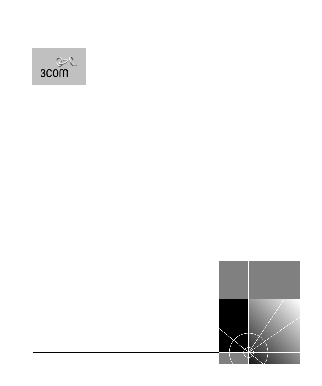
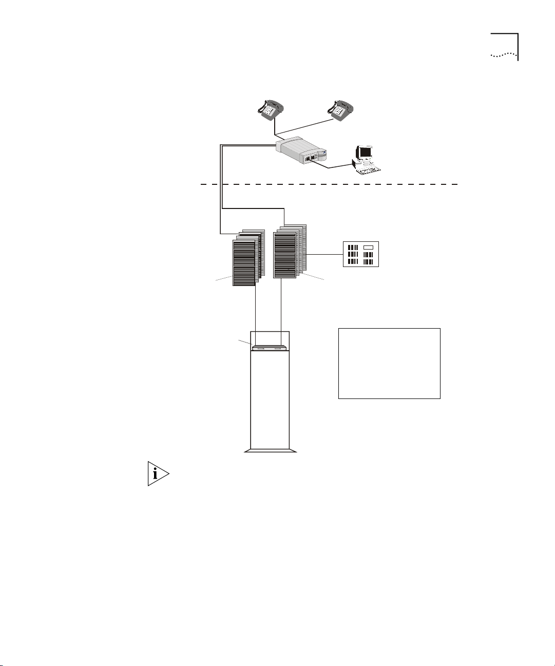
Figure 1
shows a typical MTU/MDU application.
Page 12
12 O
VERVIEW
Existing Phone
Lines
Punch-Down
Block
SuperStack II 1100 Switch
6x7x
1x
13x
18x19x
24PortsConcentrator
3
Com
VCN Access
Concentrator
Punch-Down
Block
Phone Line
Figure 1
Module
Status
Unit
green
=enabled,linkOK
flashinggreen
=disabled,linkOK
12x
off
=linkfail
4
7
11111212112
8
9
3
665
10
1
2
Packet
4
7
2
8
9
3
5
10
4
3
Status
13
Packet
151516
1818191920
232324
Power/SelfTest
14
17
212122
5
6
13
16
20
24
14
17
22
Status
7
8
24x
SuperStackII
Switch3300
3C16980
3C10BSO24OA-C
PBX
MTU/MDU Application
Ethernet
Networking Servers
Ethernet
Ethernet
VPN Router
Regular
Phone
Cable
r
e
w
e
o
n
i
Power
P
Line
L
m
e
d
o
M
-Modem
x
a
Fax
F
T
ET
E
N
N
R
R
E
H
T
E
ETHE
VCN AP
Visitor Based
T1 to ISP
PSTN
m
omo
c
3
Corporate
Intranet
Corporate
Server
Firewall
VPN Router
Internet
The VCN AC is connected to the VCN APs, the analog PBX, and an
Ethernet switch, e.g. a 3Com VCN Services Switch or a SuperStack II
Switch 1100. A standard metallic pair telephone line connects each VCN
AP to a VCN AC co-located with the analog PBX or local telephone
exchange.
The Visitor and Community Network solution also works with the
SuperStack II Switch 3300.
When a personal computer equipped with an Ethernet card is plugged
into the Ethernet port of the VCN AP, the Visitor and Community
Network system provides fast internet and other network services for
data transmissions, and allows voice channels to be used simultaneously.
Page 13

VCN AC Features 13
A person can speak on the telephone attached to the VCN AP and
simultaneously send data from his computer. A telephone extension
based on the same cable as the first telephone can be used at the same
time as the first telephone. The telephone extension does not share the
same wire pair as the computer and does not pass through the VCN AC.
Thus a hotel or a residence that installs a Visitor and Community Network
System becomes able to add many more communications services
without losing any existing capability.
The VCN AC separates voice and data channels upstream and joins voice
and data channels downstream toward the end user for all VCN APs it
services.
The Visitor and Community Network System facilitates intra-campus data
communications over a high speed Local Area Network (LAN), i.e.,
Intranet. If the campus is connected to an ISP, the system enables the
users on the campus to use the Internet.
Existing LAN infrastructure can be extended to locations currently lacking
LAN cabling through the Visitor and Community Network System.
VCN AC Features
Services that do not need the LAN, for example, voice and fax, continue
to operate normally.
The main VCN AC feature is to combine data and analog voice in the
direction of the VCN APs and to split voice and data in the direction from
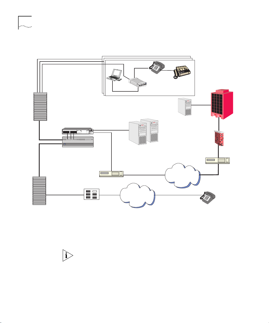
the VCN APs (see Figure 2
). Analog voice (telephone) is routed to the
analog PBX. Data is transferred to the Ethernet switch. The VCN AC
allows simultaneous transfer of voice and data of up to 10 Mbps full
duplex on each telephone extension line.
Page 14
14 O
24 Ports Conce ntrator
VERVIEW
Ethernet
frames
VCN AP
Ethernet
Figure 2
Ethernet frame
HDLC frame
VDSL fram e
Data frequency
Vo ice c all
POTS line
Transfer of Ethernet Frames in
Voice frequency
E x is t in g PO TS me ta ll ic p air lin e
Visitor and Community Network
PBX
Vo ice c alls
POTS lines
VCN AC
3
Ethernet
fra mes
Ethernet
JUHHQ
#HQDEOHG/#OLQN# 2.
IODVKLQJ#JUHHQ
#GLVDEOHG/#OLQN#2.
9[ :[
45[
RII
#OLQN#IDLO
66779988::;;<<434344444545445
3DFNHW
5
6WDWXV
3DFNHW
46464747484849494:4:4;4;4<4<535354545555565657
6WDWXV
57
4;[4<[4[46[
57[
3C16980
Ethernet sw itch
4
5
6
7
3RZHU26HOI#7HVW
8
:9;
6XSHU6WDFN#,,
6ZLWFK#6633
The user’s Ethernet frames are encapsulated in HDLC frames carried in
VDSL. Voice and data traffic are carried in their respective frequency
ranges in the wire pair that connects the VCN AP to the VCN AC. Voice
traffic, including facsimile and analog modem traffic, are not modified.
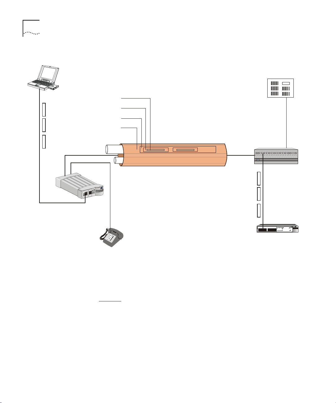
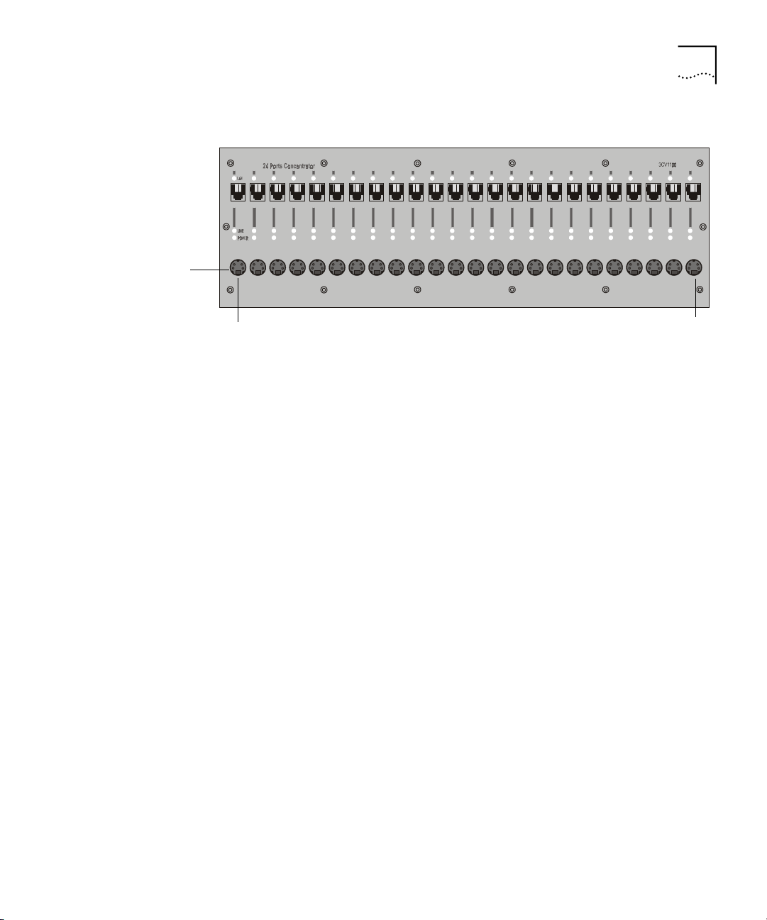
Figure 3
shows the front panel of the VCN AC. The 24 LAN ports of the
VCN AC are connected to the Ethernet switch. Each port is an RJ-45
connector.
Page 15
VCN AC Features 15
LAN LED
LAN Port
Line LED
Power LE D
Figure 3
2
1
VCN AC Front Panel
3 4 5 6 7 8 9101112131415161718192021222324
Local Management Access
(Hidden connectors)
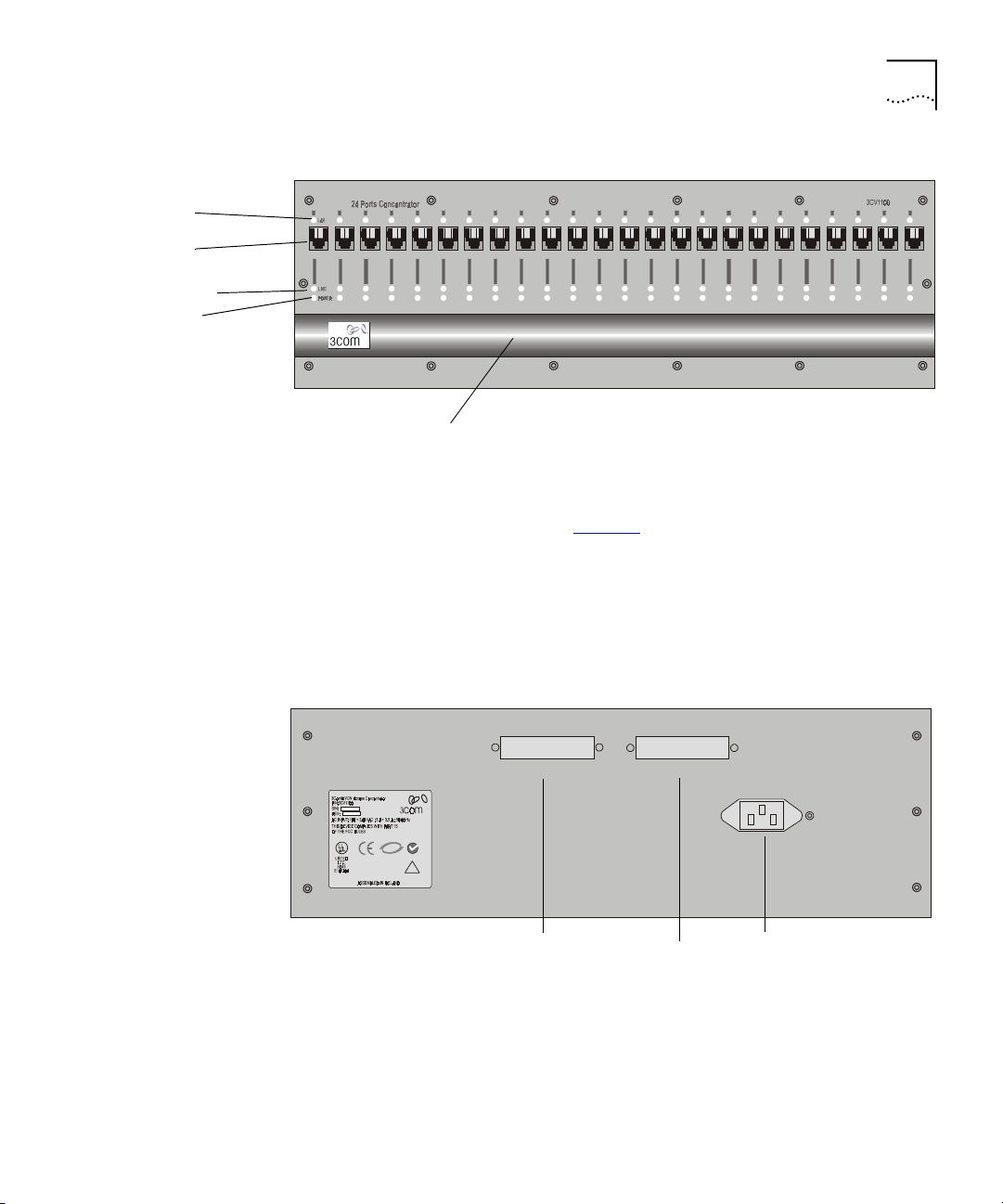
The VCN AC is connected to the VCN AP via the FROM VCN AP RJ-21
connector on the back panel (Figure 4
). The first 24 of the 25 wire pairs in
the connector, are used to connect 24 VCN APs.
The VCN AC separates the data traffic from the analog conversations.
The analog conversations are connected to the PBX via 24 of the 25 wire
pairs in the TO PBX RJ-21 connector.
Figure 4
VCN AC Back Panel
From Access Points
MIC
US
C
N151
!
RJ-21 Connected to
the VCN AP lines
TO PBX
RJ-21
Connected to
AC power input
AC-INPUT
1
1
90 - 240 V AC
the analog PBX
lines
The AC-INPUT connector on the back panel provides power to the VCN
AC.
Page 16

16 O
VERVIEW
Management
Features
The VCN AC provides the following management features:
Real Time LED Indications
The LEDs on the front panel (Figure 3
status of each line in the VCN AC. Ta b le 3
) provide real-time indications of the
describes the VCN AC front
panel LEDs.
Ta b le 3
LED State Used to
LAN Green Indicate connection of the VCN AC to the Ethernet
LINE OFF Indicate VCN AC is not connected to the line.
POWER OFF Indicate that the VCN AC is not powered.
VCN AC Front Panel LEDs
Switch.
Flashing green Indicate data transmission over the VDSL line.
Orange Indicate that the power-on self-test failed if the
LED remains orange for more than 30 seconds.
Green Indicate that the unit is functional.
Local Management
The VCN AC enables local management of every communication port.
Figure 5
shows the VCN AC front panel with the Local Management
Access (LMA) ports uncovered. For every VCN AC communication port
there is an LMA port. The LMA ports are for connecting ASCII terminals
that provide the management interface. The user monitors and manages
each communication card through a management terminal directly
attached to the card LMA port. Line status information on the VCN
AP-VCN AC connection is available.
Page 17
VCN AC Features 17
The Uncovered LMA
Ports
Figure 5
12
LMA
port 1
The Uncovered LMA ports of the VCN AC
3 4 5 6 7 8 9101112131415161718192021222324
Central Management
Central management of all VCN AC ports is performed through LMA port
1 (the leftmost LMA of the VCN AC) or Telnet. The user sends commands
to the management agent in card slot 1 through a locally attached
management terminal or remotely through a Telnet session. The
management agent controls the communications ports by sending them
commands and receiving responses through a proprietary management
message set. The user monitors and manages the VCN AC from a single
point and can view status and statistical information on the VCN AP-VCN
AC lines as well as perform certain configurational options such as setting
full or half duplex.
LMA
port 24
Remote Management
An VCN AC can be centrally and remotely managed via Telnet. Instead of
attaching a terminal to the LMA, the user connects to the VCN AC
management agent (in the leftmost card slot) though the Telnet protocol
over the Internet. Access is password protected. Messages in the
management user interface are carried in the VCN AC card slot 1 LAN
port, which is connected by an Ethernet link to an Ethernet switch. It is
not neccesary for LMA port 1 to be used.
Page 18

18 O
VERVIEW
Page 19
NSTALLING THE
I
VCN A
CCESS
2
Safety Precautions
ONCENTRATOR
C
This chapter contains safety precautions, information needed for
installing the VCN AP punch-down block, and instructions on how to
mount, install, and connect the VCN AC.
This chapter includes the following topics:
■ Safety Precautions
■ Preparing the Site for the VCN Access Concentrator
■ Installing the VCN Access Concentrator
■ Powering Up the Ethernet Switch
■ Powering Up the VCN Access Concentrator
■ Troubleshooting
WARNING: Do not plug in, turn on or attempt to operate an obviously
damaged unit.
CAUTION: All servicing should be undertaken ONLY by qualified service
personnel. there are no user serviceable parts inside the unit.
WARNING: Be sure to unplug the power supply cord from the wall
socket BEFORE attempting to remove and/or replace the power supply.
CAUTION: Do not operate the unit in location where the maximum
ambient temperature exceeds 40 degrees C.
CAUTION: Ensure that the chassis ventilation openings in the unit are
not obstructed.
Page 20
20 C
HAPTER
NSTALLING THE
2: I
CCESS CONCENTRATOR
VCN A
CAUTION: The power supply provided for automatic selection of either
100-120 VAC or 200-240 VAC, 60/50 Hz, as indicated on the safety label
adjacent to the power inlet. Ensure that the available voltage supply at
the mains is within one of these two ranges.
Précautions de Sécurité
AVERTISSEMENT: Si l'unité est visiblement endommagée NE PAS la
brancher au secteur, ni tenter de la mettre en fonction.
ATTENTION: Toute intervention sera effectuée UNIQUEMENT par un
personnel qualifié. L'unité ne comporte pas de pièces à remplacer par
l'utilisateur.
AVERTISSEMENT: Assurez vous que vous avez bien débranché le câble
d'alimentation électrique de la prise de courant AVANT d'essayer de
démonter le bloc d'alimentation.
ATTENTION: Ne pas faire fonctionner l'unité dans un endroit où la
température ambiante dépasse 40 degrés C.
ATTENTION: Vérifiez que les ouvertures de ventilation du châssis ne sont
pas obturees.
ATTENTION: Le bloc d'alimentation sélectionne automatiquement la
tension d'entrée (soit 100-120 V soit 200-240 V, alternatif 60/50 Hz)
comme indiqué sur l'étiquette de sécurité apposé à côté de la prise.
Assurez-vous que la tension disponible au secteur se trouve dans la plage
appropriée.
Sicherheitsvorkehrungen
WARNUNG: Schließen Sie die Einheit unter keinen Umständen an das
Stromnetz an, schalten diese ein oder versuchen diese zu benutzen,
wenn die Einheit klar erkennbar beschädigt ist.
VORSICHT: Alle Wartungsdienste sollten nur von qualifiziertem
Wartungspersonal durchgeführt werden. Die Einheit enthält keine Teile,
die der Benutzer selbst warten kann.
WARNUNG:
Ziehen Sie den Stromstecker aus der Steckdose,
bevor
Sie
die Energieversorgung entfernen und/oder austauschen.
Page 21

Preparing the Site for the VCN Access Concentrator 21
Preparing the Site for the VCN Access Concentrator
VORSICHT:
BEDIENEN Sie die Einheit
nicht
, wenn die Temperatur am
Standort 40 Grad C übersteigt.
VORSICHT:
Gewährleisten Sie, daß die Ventilationsöffnungen des Chassis
der Einheit nicht blockiert sind.
VORSICHT:
Die Energieversorgung wählt automatisch entweder 100-120
V WS oder 200-240 V WS, 60/50 Hz, wie auf dem Sicherheitsaufkleber
neben der Energiezufuhr angegeben. Gewährleisten Sie, daß die
vorhandene Stromleistung des Hauptstromnetzes innerhalb eines dieser
möglichen Bereiche liegt.
The punch-down block that connects POTS terminals to a PBX is known
as the PBX punch-down block. Figure 6
displays the infrastructure before
the Visitor and Community Network system is installed.
Figure 6 Before the VCN Access Concentrator is Installed
Room
Basement
Punch-Down Blocks
PBX
Before installing the VCN AC in the communications room, perform the
following tasks:
Install the VCN AP punch-down block in addition to the existing
1
punch-down block.
Install a rack for the VCN AC.
2
CAUTION:
Installation should be performed only by a qualified
technician
Page 22

22 C
HAPTER
NSTALLING THE
2: I
CCESS CONCENTRATOR
VCN A
The VCN AP punch-down block, which carries both data and voice, can
be connected to an optional patch panel, which connects the circuits
between the VCN AC and punch-down blocks.
If there is no patch panel, the VCN AC unit connects directly to the VCN
AC punch-down block and VCN AP punch-down blocks.
The VCN AC unit should be installed at the PBX punch-down block
location, usually in the basement or wiring closet of a building.
The unit is installed in a 19-inch rack along with the SuperStack II Switch
1100/3300 and an optional patch panel.
There are two methods for installing the Visitor and Community Network
system:
With a patch panel.
■
Without a patch panel.
■
Page 23

Preparing the Site for the VCN Access Concentrator 23
Installing the VCN
Access Point
Punch-down Block
with a Patch Panel
To install the VCN AP punch-down block when there is a patch panel,
perform the following steps:
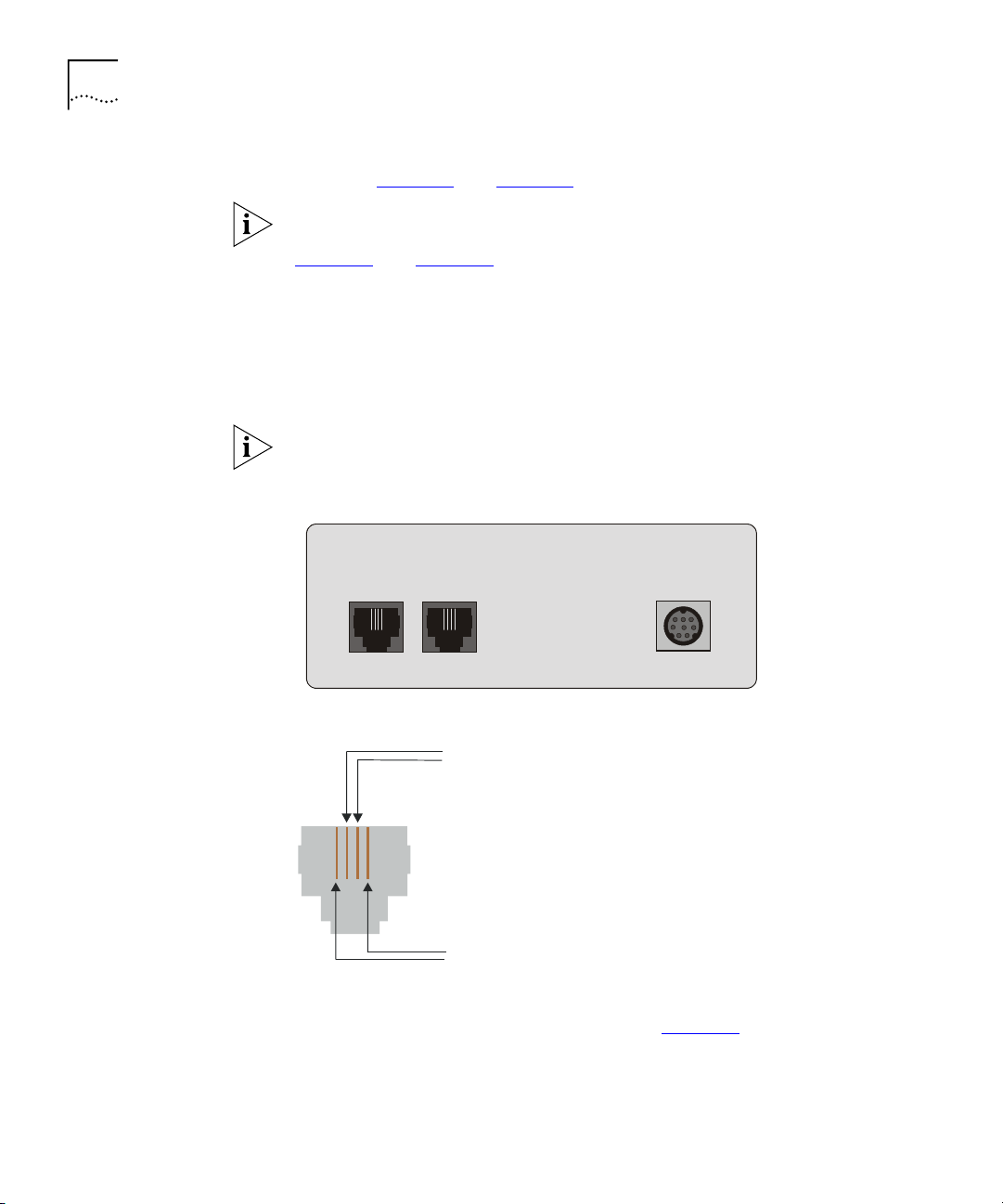
Select the wire pairs according to their position in the RJ-11 telephone
1
connector in the rear of the VCN AP. The two outside wires comprise the
outer wire pair and the two inside wires comprise the inner wire pair, as
shown in Figure 7
and Figure 8.
Where there is only one telephone line in a room, the two wires are
connected to the inner wire pair of the phone connector shown in
Figure 7
and Figure 8. The outer wire pair of the phone connector is not
used.
■ The inner wire pair carries both voice and digital date.
■ The outer wire pair carries only voice.
Figure 7 VCN Access Point Rear Pane
PHONE
LINE
DC-IN
Figure 8 The Four Wires of the Telephone Cable
Inner wire pair
Outer wire pair
Disconnect the punch-down Krone connector for the inner wire pair from
2
the PBX punch-down block.
The outer wire pair remains connected to the PBX punch-down block
since it will not carry data.
Page 24

24 C
HAPTER
NSTALLING THE
2: I
CCESS CONCENTRATOR
VCN A
Connect the Krone connector of the inner wire pair to the new VCN AP
3
punch-down block, which has been added.
Connect another punch-down Krone connector from the VCN AP
4
punch-down block to the back of the patch panel.
Connect an additional punch-down Krone connector from the patch
5
panel to the PBX punch-down block to carry voice transmissions of the
inner wire pair to the PBX.
Repeat step 1
6
Figure 9
through step 5 for up to 24 telephone lines.
shows the resulting infrastructure.
Page 25
Preparing the Site for the VCN Access Concentrator 25
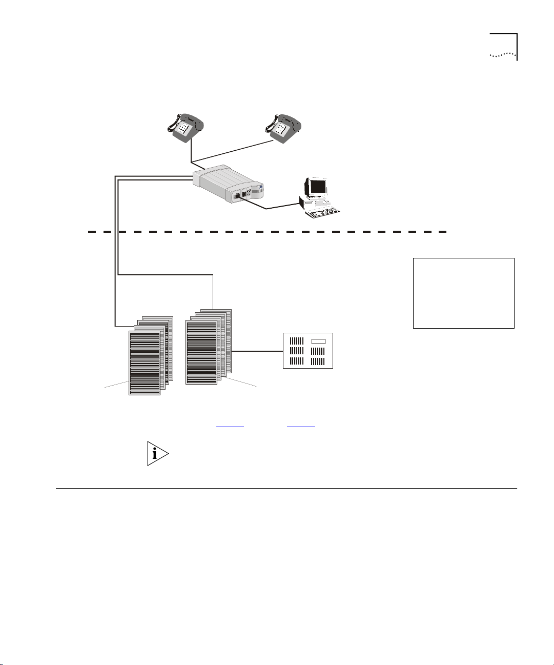
Figure 9
Wire pair
connected
to VCN AP
Ext. 1
+ Data
VCN AP punch-down
block
Patch Panel
VCN Access Point Punch-Down Block Installation with a Patch Panel
Extension 1
4-wire cable
Wire pair not
connected
to VCN AP
Punch-Down Blocks
24 wire pairs
Ext. 2
24 wire pairs
Ext. 1
TO PBXFROM VCNAP
Extension 2
VCN A ccess P oint
(VCNAP)
Ext. 1, Ext. 2
PBX punch-down
block
PBX
Note: If there is only one
extension in the room,
the wires for the second
extension are not used
and not connected to the
PBX punch down block.
Room
Basement
Installing the VCN
Access Point
Punch-Down Block
Without a Patch
Panel
The installed patch panel must have 48 wire connectors - two for each
port.
To install the VCN AP punch-down block in the absence of a patch panel,
perform the following steps:
1
Select the wire pairs according to their position in the RJ-11 telephone
connector in the rear of the VCN AP. The two outside wires comprise the
Page 26
26 C
HAPTER
NSTALLING THE
2: I
CCESS CONCENTRATOR
VCN A
outer wire pair and the two inside wires comprise the inner wire pair, as
shown in Figure 10
and Figure 11.
Where there is only one telephone line in a room, the two wires are
connected to the inner wire pair of the phone connector shown in
Figure 10
and Figure 11. The outer wire pair of the phone connector is
not used.
The inner wire pair carries both voice and digital date.
■
The outer wire pair only carries voice.
■
Disconnect the punch-down Krone connector for the inner wire pair from
2
the PBX punch-down block.
The outer wire pair remains connected to the PBX punch-down block
since it will not carry data.
Figure 10
Figure 11
Connect the punch-down Krone connector of the inner wire pair to the
3
added VCN AP punch-down block. Refer to Figure 12
VCN Access Point Rear Panel
PHONE
LINE
The Four Wires of the Telephone Cable
Inner wire pair
Outer wire Pair
DC-IN
.
Page 27
Installing the VCN Access Concentrator 27
Wire pair
connected
to VC NAP
Wire pair not
connected
to VC NAP
Ex t. 1
+ Da ta
VCN AP pun ch-down
block
Figure 12
Pane
Extension 1
Punch-Down Blocks
VCN Access Point Punch-down Block Installation without a Patch
Extension 2
VCNAP
Room
Basem ent
Note: If there is only one
Ex t. 2
PBX punch-down
PBX
block
extension in the room,
the wires for the second
extension are not used
and not connected to the
PBX punch down block.
Installing the VCN Access Concentrator
4
Repeat step 1
through step 3 for up to 24 telephone lines.
The VCN AP and PBX punch-down blocks must each have an RJ-21
connector.
Before installing the VCN AC make sure that:
■
The unit is accessible and can be connected easily.
■
Cabling is away from:
■
Sources of electrical noise such as radios, transmitters and
broadband amplifiers
■
Power lines and fluorescent lighting fixtures
■
Water or moisture cannot enter the case of the unit.
Page 28

28 C
HAPTER
NSTALLING THE
2: I
CCESS CONCENTRATOR
VCN A
Air-flow is not restricted around the unit or through the vents in the
■
side of the switch. Make sure you provide a minimum of 2.5 cm (1
inch) clearance between the SuperStack II Switch 1100/3300 and the
VCN AC
It is recommended to have a ventilated or air conditioned room.
The VCN AC is within cable reach of both the patch panel and the
■
SuperStack II Switch 1100/3300 for which the unit is to be attached.
Mounting the VCN
Access Concentrator
in the 19-inch Rack
Ta b l e 4
lists the accessories needed for mounting the VCN AC in the
19-inch rack.
Ta b le 4
No. Part Quantity
1 VCN AC unit 1
2 19-inch brackets 2
3 Handles 2
4 Screws for handles 4
5 Screws for brackets 8
The VCN Access Concentrator Accessory Set
In addition to the VCN AC unit, you will find a box containing the cable
kit needed to install the VCN AC.
Ta b l e 5
Ta b le 5
lists the cable kit parts.
The Cable Kit
No. Part Quantity
1 Power Cord 1
2 UTP CAT-5 Patch Cords 24
3 Flat cables (1.5 m each) with
RJ-21 connectors
2
Page 29
Installing the VCN Access Concentrator 29
To mount the VCN AC:
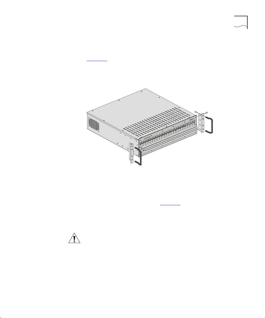
Insert one handle into the two outermost bracket holes as shown in
1
Figure 13
.
Ensure that the handle is pointing outward from the unit.
Figure 13 Fitting a Bracket for Rack Mounting
Tighten the handle from the rear with the two screws enclosed for this
2
purpose, using a number 3 Phillips screwdriver (not supplied).
Repeat steps 1 and 2 for the second handle.
3
Match the four holes of the bracket to the four mounting holes on one
4
side of the VCN AC, as shown in Figure 13
Using the four screws enclosed for this purpose, screw the bracket to the
5
.
VCN AC unit.
Repeat steps 4 and 5 for the second bracket.
6
CAUTION:
You must use the screws supplied with the mounting
brackets. Damage caused to the unit by using incorrect screws invalidates
your warranty.
Insert the VCN AC into the 19-inch rack and secure with two suitable
7
screws on each side (not provided).
Ensure that ventilation holes are not obstructed.
Page 30

30 C
HAPTER
NSTALLING THE
2: I
CCESS CONCENTRATOR
VCN A
Connecting Cables to
the Rack Via Patch
Panel
The process of connecting cables to the rack varies depending on
whether or not a patch panel is used. The procedure of connecting the
punch-down blocks to the patch-panel is described in “Preparing the Site
for the VCN Access Concentrator” on page 21.
Back Panel Connections
To connect the back panel of the VCN AC, use the 2 flat cables with RJ-21
connectors supplied with the VCN AC.
To connect the VCN AC to the patch-panel, perform the following steps:
Connect the RJ-21 connector labeled “FROM VCN AP” at the back of the
1
VCN AC to the “FROM VCN AP” connector on the front of the patch
panel using one of the 50-pin twisted pair flat cables.
Connect the RJ-21 connector labeled “TO PBX” at the back of the VCN
2
AC to the “TO PBX” connector on the front of the patch panel using the
second 50-pin twisted pair flat cable.
Page 31

Front Panel Connections
Installing the VCN Access Concentrator 31
Refer to “Preparing the Site for the VCN Access Concentrator”
page 21
before connecting the VCN AC to the SuperStack II Switch
on
1100/3300 through the front.
Figure 14
Figure 14 Patch Panel and the SuperStack II Switch 1100/3300 Connected to
the VCN Access Concentrator
Switch 1100/3300
displays the rack after it has been wire connected.
Patch Panel
TO PBXFROM NAU
Flat Cable
JUHHQ
#HQDEOHG/#OLQN# 2.
IODVKLQJ#JUHHQ
#GLVDEOHG/#OLQN#2.
9[: [
4[
45[
RII
#OLQN#IDLO
66779988::;;<<434344444545445
4
SuperStack II
46[
4;[4<[
123 45 678 9101112131415161718192021222324
3
VCN AC
5 6
46464747484849494:4:4;4;4<4<535354545555565657
57[
3C16980
5
3DFNHW
7
6WDWXV
8
3DFNHW
3RZHU26HOI#7HVW
57
:9;
6WDWXV
6XSHU6WDFN#,,
66,,4433#6633
24 RJ-45 connections
between VCN A C
and the SuperS tack II
Switch 1100/3300
Figure 15 shows all the connections in the network.
Page 32

32 C
HAPTER
NSTALLING THE
2: I
CCESS CONCENTRATOR
VCN A
Figure 15
VCN AP punch-dow n
block
24 wire pairs
VCN Access Concentrator Installed with a Patch Panel
VCN AP
Punch-Dow n Block
PBX
PBX punch-dow n
block
24 wire pairs
Room
Basement
Patch Panel
RJ-21
Connector
from VCN AP
Flat Cable
RJ-21
Connector
TO PBXFROM VCNAP
12 34 56 78 9101112131415161718192021222324
24
lines
RJ-21
Connector
to P BX
RJ-21
Connector
Ethernet Sw itch
9[ :[
4;[4<[4[46[
JUHHQ
#HQDEOHG/#OLQN#2.
IODVKLQJ#JUHHQ
#GLVDEOHG/#OLQN#2.
45[
RII
#OLQN#IDLO
6
6779988::;;<<4343444445454455 6
46464747484849494:4:4;4;4<4<535354545555565657
57
57[
3C16980
4
5
3DFNHW
7
6WDWXV
8
3DFNHW
3RZHU26HOI#7HVW
:9;
6WDWXV
6XSHU6WDFN#,,
6ZLWFK#6633
VCN AC
POWER
T1
ISP
Router
Using RJ-45 connector terminated cables, connect the VCN AC LAN ports
to the Ethernet switch.
Page 33

Installing the VCN Access Concentrator 33
If your switch is the SuperStack II 1100 or 3300, connect to the front
panel ports. If your switch is not the SuperStack II 1100 or 3300, follow
the procedures for your switch.
Note on Insertion of
Line Cards in the VCN
Access Concentrator
Connecting Cables to
the Rack Without a
Patch Panel
Note the following:
The card in VCN AC slot 1 provides central management and is different
from the remaining cards. This card has a factory installed MAC address
and must not be inserted in any slot other than slot 1.
This section describes how to connect the rack without a patch panel.
The VCN AC connects directly to the VCN AP and PBX punch-down
blocks at the back with RJ-21 connectors.
Back Panel Connections
Perform the following steps to connect the VCN AC to the punch-down
blocks.
Connect one RJ-21 flat cable to the VCN AP punch-down block through
1
the RJ-21 connector labeled “FROM VCN AP”.
Connect the other RJ-21 flat cable to the PBX punch-down block through
2
the RJ-21 connector labeled “TO PBX”.
To connect the back panel of the VCN AC, use the 2 flat cables with RJ-21
connectors supplied with the VCN AC.
The pin assignments of the two RJ-21 connectors at the back of the VCN
AC must match the pin assignments of the RJ-21 connectors of the two
punch-down blocks.
To correctly align the RJ-21 connectors on the VCN AC and the
punch-down blocks, see Ta b le 6
Ta b le 6 Pin Assignment for the RJ-21 Connector
VCN AC Port No. First Pin Second Pin
1 1 26
2 2 27
3 3 28
4 4 29
.
Page 34

34 C
HAPTER
NSTALLING THE
2: I
CCESS CONCENTRATOR
VCN A
Ta b le 6
Pin Assignment for the RJ-21 Connector (continued)
VCN AC Port No. First Pin Second Pin
5 5 30
6 6 31
7 7 32
8 8 33
9 9 34
10 10 35
11 11 36
12 12 37
13 13 38
14 14 39
15 15 40
16 16 41
17 17 42
18 18 43
19 19 44
20 20 45
21 21 46
22 22 47
23 23 48
24 24 49
Figure 16 depicts the pin numbering scheme on the female RJ-21
connectors which are used on both the “TO PBX” and the “From Access
Points” ports on the VCN AC.
Figure 16
Female RJ-21 Connector
125
Page 35

Front Panel Connections
Installing the VCN Access Concentrator 35
Refer to “Preparing the Site for the VCN Access Concentrator”
page 21
before connecting the VCN AC to SuperStack II Switch
on
1100/3300 through the front.
Figure 17
displays the infrastructure after the VCN AC has been installed
without a patch panel.
Figure 17 The VCN Access Concentrator Unit Installed Without a Patch Panel
VCN AP
Room
24 wire pairs
VCN AP punch-down
block
Punch-Down Blocks
PBX punch-down
block
PBX
Basement
Flat Cable
VCN AC
123456789101112131415161718192021222324
3
POWER
Office C onnect Router
Router
T1
24 RJ-45 connections
between the VCN A C
and the Ethernet
Switch
JUHHQ
#HQDEOHG/#OLQN#2.
IODVKLQJ#JUHHQ
#GLVDEOHG/#OLQN#2.
9[:[
45[
RII
#OLQN#IDLO
66779988::;;<<434344444545445
5 6
46464747484849494:4:4;4;4<4<535354545555565657
4;[4<[4[46[
57[
3C16980
Ethernet
Switch
4
5
3DFNHW
7
6WDWXV
8
3DFNHW
3RZHU26HOI#7HVW
:9;
57
6WDWXV
6XSHU6WDFN#,,
66,,4433#6633
Using RJ-45 connector terminated cables, connect the VCN AC LAN ports
to the Ethernet switch.
Page 36

36 C
HAPTER
NSTALLING THE
2: I
CCESS CONCENTRATOR
VCN A
If your switch is the SuperStack II 1100 or 3300, connect to the front
panel ports. If your switch is not the SuperStack II 1100 or 3300, follow
the procedures for your switch.
Mounting the
Ethernet Switch
Configuring the
Ethernet Switch for
the VCN Access
Concentrator
For instructions on mounting and powering-up the SuperStack II Switch
1100, see the
SuperStack II Switch 1100/3300 User Guide.
If your switch is not a SuperStack II 1100 or 3300, follow the procedures
for your switch.
This section describes the procedure for configuring the Ethernet switch.
Sequence of Configuration
The following is the sequence of configuration actions:
Define the desired VLANs, if any, on your switch.
1
Define the MAC addresses for all of the 24 VCN AC ports and all APs
2
attached to the AC.
Connect the VCN AC.
3
Defining the VLANs after the VCN AC and AP MAC addresses may make
some of the addresses inaccessible.
The default VCN AC VLAN for management is VLAN 1 tagged.
If MAC addresses are not defined before the VCN AC is connected, the
switch will flood the entire network with the initial messages sent
through the VCN AC, since the destination addresses are unknown.
Not more than one VCN AC may be connected to a switch.
The remainder of this section describes the procedure for defining MAC
addresses for the VCN AC and VCN APs.
Inserting MAC Addresses for VCN Access Concentrator Ports
Detailed instructions are presented here for both manual and automated
procedures for the SuperStack II 1100 and 3300 Ethernet switches.
General guidance is provided for non-SuperStack switches.
Page 37

Installing the VCN Access Concentrator 37
Procedures for a non-SuperStack Switch Automated procedures for
non-SuperStack switches are not available. For a non-SuperStack switch,
the Manual Procedures for SuperStack II 1100/3300
serve as a general
outline for manual MAC address insertion, but the user follows the
detailed instructions in the non-SuperStack switch user guide. Implement
the MAC addresses listed in Ta b l e 7
for the VCN AC. Repeat the
procedure to define the MAC addresses of the 24 VCN APs attached to
the VCN AC. Start with the lowest VCN AP MAC address of
00-C0-DA-40-80-19 and assign addresses for up to 24 VCN APs
consecutively.
Manual Procedures for SuperStack II 1100/3300 Enter every one of
the 24 VCN AC port MAC addresses through the SuperStack II web
management interface.
Refer to the SuperStack® II Switch Management Guide, and follow the
instructions in the section “Inserting Permanent Entries” for the Switch
Database dialog. You will need to use a web browser on the computer
connected to the switch.
Insert the VCN AC port MAC addresses before connecting the VCN AC to
the Ethernet switch.
To manually insert a MAC address for an VCN AC port:
From the
1
Ignore the
In the
2
Port Filter
VLAN Filter
Enter MAC Address
list box, select a port for the entry.
list box.
field, enter the MAC (Ethernet) address for the
port.
From the
3
Click the
4
Select Action Type
button.
Apply
list box, select
Insert
.
The Display Database Entries table displays the new entry.
Repeat steps 1 through 4 for every port.
5
The Display Database Entries table is not automatically updated with the
new entry.
To update the table:
From the
1
Click the
2
Select Action Type
button
Apply
list box, select Display All
.
.
Page 38

38 C
HAPTER
NSTALLING THE
2: I
CCESS CONCENTRATOR
VCN A
Ta b l e 7 lists the MAC addresses in hexadecimal format.
Repeat the procedure to define the MAC addresses of the 24 VCN APs.
Start with the lowest VCN AP MAC address of 00-C0-DA-40-80-19 and
assign addresses consecutively.
Ta b le 7
VCN AC
Port No. MAC Address
1 00-C0-DA-40-80-01 1 00-C0-DA-40-80-19
2 00-C0-DA-40-80-02 2 00-C0-DA-40-80-1A
3 00-C0-DA-40-80-03 3 00-C0-DA-40-80-1B
4 00-C0-DA-40-80-04 4 00-C0-DA-40-80-1C
5 00-C0-DA-40-80-05 5 00-C0-DA-40-80-1D
6 00-C0-DA-40-80-06 6 00-C0-DA-40-80-1E
7 00-C0-DA-40-80-07 7 00-C0-DA-40-80-1F
8 00-C0-DA-40-80-08 8 00-C0-DA-40-80-20
9 00-C0-DA-40-80-09 9 00-C0-DA-40-80-21
10 00-C0-DA-40-80-0A 10 00-C0-DA-40-80-22
11 00-C0-DA-40-80-0B 11 00-C0-DA-40-80-23
12 00-C0-DA-40-80-0C 12 00-C0-DA-40-80-24
13 00-C0-DA-40-80-0D 13 00-C0-DA-40-80-25
14 00-C0-DA-40-80-0E 14 00-C0-DA-40-80-26
15 00-C0-DA-40-80-0F 15 00-C0-DA-40-80-27
16 00-C0-DA-40-80-10 16 00-C0-DA-40-80-28
17 00-C0-DA-40-80-11 17 00-C0-DA-40-80-29
18 00-C0-DA-40-80-12 18 00-C0-DA-40-80-2A
19 00-C0-DA-40-80-13 19 00-C0-DA-40-80-2B
20 00-C0-DA-40-80-14 20 00-C0-DA-40-80-2C
21 00-C0-DA-40-80-15 21 00-C0-DA-40-80-2D
22 00-C0-DA-40-80-16 22 00-C0-DA-40-80-2E
23 00-C0-DA-40-80-17 23 00-C0-DA-40-80-2F
24 00-C0-DA-40-80-18 24 00-C0-DA-40-80-30
VCN AC Port and VCN AP MAC Addresses
VCN AP
No. MAC Address
Every VCN AC and attached VCN APs have the same set of 48 MAC
addresses.
Page 39

Installing the VCN Access Concentrator 39
The VCN AC connects to the SuperStack II Switch 1100/3300 from the
front. Connect the VCN AC and the SuperStack II Switch 1100/3300 with
up to 24 RJ-45 connections, one for each port. All ports use the UTP CAT
5 patch cords supplied with the VCN AC.
The MAC addresses differ only in the 2 lowest order numbers. After the
first address is entered, the user needs to change only the two right-most
numbers while entering each address.
Page 40

40 C
HAPTER
NSTALLING THE
2: I
CCESS CONCENTRATOR
VCN A
Automated Procedures for SuperStack II 1100/3300
The automated procedure uses files fetched from the 3Com web site
http://support.3com.com/software/vcns.htm. Use a PC with one of the
following Microsoft operating systems:
Windows 95
■
Windows 98
■
Windows 2000
■
Windows NT4
■
Download the files from the web site into your PC. One of the files is
ConfApp.exe. The remaining files are dlls that support the ConfApp
application.
Connect your PC to any IP-based network to which the switch is
connected. Figure 18
shows the station connected to an Ethernet
containing the SuperStack II switch.
Figure 18
Connection of Management Station
1x
13x
6x 7x
18x 19x
12x
TCVR
24x
3C16950
= enabled, link OK
green
= disabled, link OK
flashing green
= link fail
off
334466557788991010111112
112
2
13
1314141515161617171818191920202121222223232424
1
25x 26x
25 26 Packet
25 26 Status
2
3
4
5
Power/Self Test
768
SuperStack II
Switch 1100
Packet
12
Status
Packet
Status
To install VCN AC and VCN AP addresses at one or more SuperStack II
1100/3300 switches, perform the following steps:
Run the ConfApp application; do one of the following:
1
Double click the
■
Double click
■
Select
■
Start
ConfApp.exe
ConfApp
ConfApp.exe
>
; type the
Run
and press <Enter>.
icon in the Windows desktop.
in its folder displayed under My Computer.
ConfApp.exe
path followed by
Page 41

Installing the VCN Access Concentrator 41
The
ConfApp
Figure 19 ConfApp Screen
Add
browser
window
To select a switch, type the switch <
2
address appears in the
screen appears (Figure 19).
browser window (Figure 20
Add
IP address> in the
data field. The
IP
).
Page 42

42 C
HAPTER
NSTALLING THE
2: I
CCESS CONCENTRATOR
VCN A
Figure 20
Click the
3
field if <
Ty pe t h e
a
Entering the Switch Address
Community
Community string>
<Community string>
checkbox to enable changing the
non-default value. See Figure 21
applies.
in the
.
Community
Community
data
data field to enter a
The default
Community string is private.
Page 43

Installing the VCN Access Concentrator 43
Figure 21
4
To be able to install the VCN AC and VCN AP MAC addresses, click
If the IP address is invalid, it appears red in the
Community Parameter
browser window.
Add
Add
.
To delete an erroneous IP address, select the address in the
window and click
Remove
. See Figure 22
.
Add
browser
Page 44

44 C
HAPTER
NSTALLING THE
2: I
CCESS CONCENTRATOR
VCN A
Figure 22
Removing Wrong Address
To configure additional SuperStack II switches, repeat step 2 through
step 4
.
After all switches have been selected, click
5
. Clicking
Set
configures
Set
switches with valid VCN AC and VCN AP IP addresses.
Switches corresponding to invalid IP addresses are not configured with
the VCN AC and VCN AP MAC addresses. Error messages appear in the
ConfApp screen when a
addresses. Similarly, attempting to
operation is attempted for invalid IP
Set
a switch which is not connected to
Set
a VCN AC results in the same error messages.
For each wrong switch address the following message appears:
Error Setting the agent.
Click OK to close the message.
At the end of the entire
operation the following message appears to
Set
inform that the set operation is complete and that switches at invalid
addresses are not configured:
End of Setting.
Agents from red lines were not set!
Page 45

Powering Up the Ethernet Switch 45
Powering Up the Ethernet Switch
Erroneous switch addresses appear in red at the end of the
operation.
Set
Click OK to close the message.
If there are no errors at the end of the entire
operation, the following
Set
message appears:
All agents were set successfully.
Click OK to close the message.
More switch addresses can be entered in the menu after each set
operation. Previously used addresses can be removed by selecting them
and clicking
Remove
When you are finished, click
. You can execute any number of set operations.
.
Close
For instructions on powering-up the SuperStack II Switch 1100/3300, see
the SuperStack II Switch 1100/3300 User Guide.
For other switches, see the corresponding user guide
Powering Up the VCN Access Concentrator
Proper Selection of
Power Cord
The VCN AC does not have a power switch. It is powered-up once the
power cord is plugged into the back of the VCN AC and to the mains.
Review the following instructions for proper selection of the power cord
for this unit:
CAUTION:
Use only the power cord supplied with this unit.
If power cord(s) were not supplied with the unit, select as follows:
■
For units installed in the USA and Canada:
Select a flexible,
three-conductor power cord that is UL-listed and CSA certified, with
individual conductor wire size of #18 AWG, and with maximum
length of 4.5 meters. The power cord termination should be MEMA
Type 5-15P (three prong earthing) at one end and IEC appliance inlet
coupler at the other end.
Page 46

46 C
HAPTER
NSTALLING THE
2: I
CCESS CONCENTRATOR
VCN A
The following types are acceptable: SV, SVE, SVO, SVT, SVTO, SVTOO,
S, SE, SO, SOO, ST, STO, STOO,SJ, SJE, SJO, SJOO, SJT, SJTOO, SP-3,
SPE-3, SPT-3, G, W.
For units installed in all other countries: Select ONLY a flexible,
■
three-conductor power cord, approved by the cognizant safety
organization of your country. The power cord must by type HAR
(harmonized), with individual conductor wire size of 0.75 sq.mm. The
power cord termination should be a suitably-rated earthing-type plug
at on end and IEC appliance inlet coupler at the other end. Both of the
power cord terminations must carry the certification label (mark) of
the cognizant safety organization of your country.
Selection Du Cable
D'alimentation
Examinez les instructions suivantes pour sélectionner le câble
d'alimentation de l'unité.
ATTENTION: Utilisez seulement le câble d'alimentation fourni avec
l'unité.
Au cas où un câble d'alimentation n'a pas été fourni avec l'unité,
sélectionnez le câble selon les instructions suivantes:
■
Pour les unités installées aux USA et au Canada
: Sélectionner un
câble flexible, à trois conducteurs qui se trouve dans la liste UL et est
certifié CSA; le diamètre de chaque conducteur doit être #18 AWG,
d'une longueur maximale de 4,5 mètres. Le câble doit être équipé de
prise MEMA Type 5-15P (masse triple) à une extrémité et prise
d'appareil IEC à l'autre extrémité.
Chacun des types suivants est acceptable: SV, SVE, SVO, SVT, SVTO,
SVTOO, S, SE, SO, SOO, ST, STO, STOO, SJ, SJE, SJO, SJOO, SJT,
SJTOO, SP-3, SPE-3, SPT-3, G, W.
■
Pour les unités installées dans d'autres pays
Sélectionner
UNIQUEMENT un câble flexible, à trois conducteurs, approuvé par
l'organisme approprié de sécurité. Le câble électrique DOIT ÊTRE de
Type HAR (Harmonisé), le diamètre de chaque conducteur doit être de
0,75 mm2. Une extrémité du câble doit être équipée d'une prise avec
mise à la masse appropriée IEC, l'autre d'une prise d'accouplement.
Les deux extrémités du câble doivent comporter les marques de
l'organisme de sécurité du pays correspondant.
Richtige Auswahl des
Stromkabels
Lesen Sie die nachstehenden Anweisungen zur Auswahl des Stromkabels
für diese Einheit genauestens.
Page 47

Troubleshooting 47
VORSICHT:
Verwenden Sie ausschließlich die Stromkabel, die mit dieser
Einheit geliefert werden.
Falls KEIN(E) Stromkabel mit der Einheit geliefert wurden, wählen Sie
unter den nachstehend genannten Möglichkeiten aus:
■
Für Einheiten, die in den U.S.A. und Kanada installiert werden:
Wählen Sie ein flexibles drei-phasiges Stromkabel mit individueller
Kabeldrahtgröße der Nr. 18 AWG und mit einer maximalen Länge von
4,5 Metern. Das Kabel muß in der IL-Liste geführt werden und von
CSA zugelassen sein. Das Kabel sollte an einem Ende mit einem
Stecker des Typs MEMA 5-15P (drei-polige Erdung) ausgestattet sein
und am anderen Ende mit einem IEC Gerätestecker.
Die folgenden Typen sind akzeptierbar: SV, SVE, SVO, SVT, SVTO,
SVTOO, S, SE, SO, SOO, ST, STO, STOO, SJ, SJE, SJO, SJOO, SJT,
SJTOO, SP-3, SPE-3, SPT-3, G, W.
■
Für Einheiten, die in anderen Ländern installiert werden:
wählen
Sie AUSSCHLIESSLICH ein flexibles, drei-phasiges Stromkabel, das in
Ihrem Land durch die zuständige Organisation für
Sicherheitsbestimmungen genehmigt ist. Das Stromkabel MUSS vom
Typ HAR (harmonisiert) mit einer individuellen Größe von 0,75 mm2
sein. Das Kabel sollte mit einem geeigneten Stecker mit Erdung an
einem Ende ausgestattet sein und mit einem IEC Gerätestecker am
anderen Ende. Beide Kabelenden müssen einen Zulassungsaufkleber
der zuständigen Organisation für Sicherheitsbestimmungen Ihres
Landes aufweisen.
Troubleshooting
See on page 16, for VCN AC LED states. For more information, refer to
Appendix A
CAUTION:
Troubleshooting.
All servicing should be undertaken ONLY by qualified service
personnel. There are no user serviceable parts inside the unit.
Page 48

48 C
HAPTER
NSTALLING THE
2: I
CCESS CONCENTRATOR
VCN A
Page 49

ANAGING THE
M
VCN A
CCESS
3
Real Time LED Indications
LAN LED
ONCENTRATOR
C
This chapter describes the following:
■ Real Time LED Indications
■ Using the Management Terminal for Local and Central Management
■ Line Card Management
■ Central Management
■ Remote Software Download
The LEDs on the front panel (Figure 23) provide real-time indications of
the status of each line in the VCN AC.
Figure 23
VCN Access Concentrator Front Panel
LAN Port
Line LED
Power LE D
3 4 5 6 7 8 9101112131415161718192021222324
2
1
Local Management Access
(Hidden connectors)
Page 50

50 M
ANAGING THE
CCESS CONCENTRATOR
VCN A
Ta b l e 8 describes the VCN AC front panel LEDs.
Using the Management Terminal for Local and Central Management
Management
Te r m i n a l
Requirements
Ta b le 8
LED State Used to
LAN Green Indicate connection of the VCN AC to the Ethernet
LINE OFF Indicate VCN AC is not connected to the line.
POWER OFF Indicate that the VCN AC is not powered.
VCN Access Concentrator Front Panel LEDs and Connectors
Switch.
Flashing green Indicate data transmission over the VDSL line.
Orange Indicate that the power-on self-test failed if the
LED remains orange for more than 30 seconds.
Green Indicate that the unit is functional.
For service and maintenance through local or central management, you
need a terminal or computer used as a terminal emulator.
Use a PC equipped with a terminal application capable of 115,200 bps
serial communication with a VCN AC. Refer to Appendix C
Te r m i n a l
Emulation Settings.
Page 51

Using the Management Terminal for Local and Central Management 51
Connecting the PC
Terminal Emulator
To connect the PC to the LMA port:
Remove the cover from the LMA section of the VCN AC, shown in
1
Figure 24
cover loose to reveal the LMA section shown in Figure 25
Figure 24 Removing the Cover from the LMA Section
. Insert a screw driver in each of the three grooves and pry the
.
Grooves
For Removal
Of Strip
The Uncovered LMA
Ports
Figure 25 The Uncovered LMA Section of VCN Access Concentrator
3 4 5 6 7 8 9101112131415161718192021222324
2
1
LMA
port 1
LMA
port 24
Page 52

52 M
ANAGING THE
CCESS CONCENTRATOR
VCN A
Connect the LMA port to the PC serial port (COM1 or 2) with the cable
2
provided.
Plug the end of the cable with the four-pin MiniDIN connector into one of
3
the 24 VCN AC LMA ports. For central management or to manage the
first port, plug the MiniDIN into port LMA port 1. To locally manage
another port, plug the MiniDIN into the LMA connector of that port.
Line Card Management
Local Menus
This section describes local management.
All lower level menus are accessed by selecting a menu item from the
menu you are viewing and typing the item number. You return to the
previous menu, the higher level menu, by typing
0 (zero) and pressing
<Enter>.
In this section you will find information on how to monitor and control an
LC through its LMA port.
In most menus, except where indicated, the option labeled
returning to a higher level menu (Figure 26
Figure 26
0. Return to previous menu
Return to Previous Menu Option
).
is for
0
Login
After connecting the management terminal to one of the LMA ports 2
through 24, press any key. The login dialog appears:
Login:
Type your Login ID and press <Enter>.
Password:
Type your password and press <Enter>.
The default login is
admin; the default password is null—just press
<Enter>.
If you make a mistake in your Login ID, an error message appears:
Login incorrect
Page 53

Line Card Management 53
If you forget your password, contact technical support. Refer to
Appendix D
Technical Support.
Line Card Main Menu
The
Line Card Main Menu
appears at the end of the login dialog.
If another menu appears, type
the
Line Card Main Menu
0 (zero) and press <Enter> repeatedly until
appears as shown in Figure 27
. This menu
allows you to manage the port.
Figure 27 Line Card Main Menu
Line Card Main Menu
-------------------
1. LC version
2. Debug menu
3. Management menu
4. VDSL control
5. Test control
6. Flash actions
7. LC Configuration
0. Exit
Please enter your choice:
Line Card Menu Hierarchy and Summary
This section provides a menu hierarchy to describe the structure of the
menu system and a menu summary to help the network administrator
use the management system efficiently.
The chart in Figure 28
summarizes the menu hierarchy. The abbreviations
next to the menu names are suggestions for how the menus are used.
Most of the menus labeled D are not described further in this chapter
since they are used mainly by developers for debugging. The debug
menus for performing loopbacks are described since loopbacks can be
used by network administrators in problem solving.
Page 54

54 M
ANAGING THE
CCESS CONCENTRATOR
VCN A
Login Process
Line Card Menu
KEY
Configuration
C
M
Monitoring system
operation and problem
reporting
P
Problem Solving
S
Software Download
D
Debug, for developers
use only
Figure 28
Management
Menu
D
Debug Menu
D
Test Control
D
Flash Actions
C
LC Configuration
M
VDSL Control
P
LC Version
Line Card Menu Structure
M
Ethernet
Menu
M
HDLC Menu
D
Tasks Info Menu
S
P
Reset Board
P
Reset All Counters
C
Set VLAN ID for Management
C
Set Ethernet Half/Full Duplex Mode
C
Change Password
C
Set to Factory Defaults
M
QAM Channel Status
S D
Change
P
Work Mode
P
Ethernet Status
M
Traffic Counters
P
Reset Counters
D
Change
Work Mode
P
HDLC Status
M
Traffic Counters
P
Reset Counters
Operation
Mode Selector
P
Set Normal Mode
D
Set Internal
Loopback Mode
P
Set External
Loopback Mode
D
Set Full Duplex
Mode
D
D
D
Read BCM6010 register
D
Write BCM6010 register
D
I2C control
D
VDSL print
Set Normal Mode
Set Internal
Loopback Mode
Ta bl e 9 provides a summary of the line card menus, the submenus and
the corresponding number sequence. Click a menu or submenu name to
receive more information.
After typing each number in the number sequence press the <Enter> key.
Page 55

Line Card Management 55
Ta b le 9 Number Sequence Corresponding to Submenus
Menu Name Submenu
Line Card Main Menu
LC Version 1
Management Menu 3
The Ethernet Menu 31
Ethernet Traffic Counters 3 1 1
Ethernet Status 3 1 2
Reset Ethernet Counters 3 1 3
Change Ethernet Work Mode Menu 3 1 4
The HDLC Menu 3 2
HDLC Traffic Counters 3 2 1
HDLC Status 3 2 2
Reset HDLC Counters 3 2 3
Change HDLC Work Mode 3 2 4
Reset All Counters 3 4
Reset the Line Card 3 5
The VDSL Control Menu 4
VDSL QAM Channel Status Report 4 1
The LC Configuration Menu 7
Set VLAN ID for Management 7 1
Set Ethernet Half/Full Duplex Mode 7 2
Change Password 7 3
Set to Factory Defaults 7 4
Number
Sequence
When you are finished using the local management menus, exit your
terminal emulation program and disconnect your personal computer
from the Local Management port.
Line Card Main Menu of Port 1
The
Line Card Main Menu
of Central Management (refer to the section Central
Menu
Management). It is identical to the
except for option
Main Menu
the
VCN Access Concentrator Menu
0
. In the Port 1 Line Card Main Menu, entering option
of Port 1 (Figure 29
Line Card Main Menu
which returns the user to the Central Management
to appear.
) is entered from the
of other ports
0 causes
Main
Page 56

56 M
ANAGING THE
CCESS CONCENTRATOR
VCN A
Figure 29
Line Card Main Menu
-------------------
1. LC version
2. Debug menu
3. Management menu
4. VDSL control
5. Test control
6. Flash actions
7. LC Configuration
0. Return to previous menu
Please enter your choice:
Line Card Main Menu of Port 1
LC Version
To check the software and hardware version of the line card (LC), type
in the
Line Card Main Menu
Figure 30
System Display
-------------HW Version: 1.0
SW Version: 3.5
SW Date: Jul 16 2000,
SW Time: 10:56:28
LC Slot Number: 1
Version Screen
. The screen in Figure 30
appears:
1
Press ENTER to continue ...
Press <Enter> to return to the Line Card Main Menu.
Page 57

Management Menu
To d is p l a y t h e
Management Menu
and press <Enter>. The
Management Menu
, type
appears.
Figure 31 Line Card Management Menu
Management Menu
---------------
1. Ethernet Menu
2. HDLC Menu
3. Tasks Info Menu
4. Reset All Counters
5. Reset Board
0. Return to Previous Menu
Please enter your choice:
The Ethernet Menu
Line Card Management 57
3 in the
Line Card Main Menu
, shown in Figure 31
,
To view the Ethernet menu:
In the
1
2
Line Card Main Menu
In the
Management Menu
Figure 32
appear.
type 3 and press <Enter>.
1 and press <Enter>. The options in
, type
Page 58

58 M
ANAGING THE
CCESS CONCENTRATOR
VCN A
Figure 32
1. Traffic Counters
2. Ethernet Status
3. Reset Counters
4. Change Work Mode
0. Return to Previous Menu
Please Enter your choice:
The
Table 10
Ethernet Menu
Options Feature How to use
Traffic counters Displays traffic counters Refer to “Ethernet Traffic
Ethernet Status Displays line status, including
Reset Counters Returns traffic counters to
Change Work Mode Enables setting internal and
The Ethernet Menu
Ethernet Menu
-------------
Ethernet Menu
Ethernet Menu Options
options are described in Ta b l e 1 0 .
Counters” on page 58.
Refer to “Ethernet Status”
normal or loopback mode
and duplex mode
zero
external loopbacks, normal
mode, and the setting of half
and full duplex mode
on page 59.
To reset Ethernet counters
from the
type 3 and press <Enter>.
Refer to “Change Ethernet
Work Mode Menu” on
page 60.
Ethernet Menu
,
Ethernet Traffic Counters
The Ethernet traffic counters count normal frames and errored frames
transferred between the VCN AC and the Ethernet Switch.
To check the Ethernet traffic counters, type
(Figure 32
), and press <Enter> to view Ethernet traffic counters; the
Ethernet traffic counters screen appears (Figure 33
in the Ethernet Menu
1
).
Page 59

Line Card Management 59
Figure 33
Transmit counters
Tx frames - 148361
Tx errors - 41
Discards - 0
Receive counters
Rx frames - 148361
Rx frames - 0
CRC errors - 0
Discarded - 0
Alignment errors - 0
Overruns - 0
Collisions - 0
Frames too long - 0
Frames too short - 0
Press ENTER to continue ...
A Typical Ethernet Traffic Counters Screen
Ethernet Traffic Counters
-------------------------
Ethernet Status
To check Ethernet line status, type
Menu
Ethernet Status
; the
screen in Figure 34
2
and press <Enter> in the
appears:
Ethernet
Page 60

60 M
ANAGING THE
CCESS CONCENTRATOR
VCN A
Figure 34
Scc channel numbers - 2
Work mode - normal operation
Transmit enable - yes
Receive enable - yes
Heartbeat checking - no
Retry limit - 15
Maximum length of rx frame - 1522 bytes
Minimum length of rx frame - 64 bytes
Press <Enter> to continue ...
Ethernet Status Screen
Ethernet status
---------------
Reset Ethernet Counters
To reset Ethernet counters, type
in the Ethernet Menu and press
3
<Enter>.
Change Ethernet Work Mode Menu
To change the Ethernet loopback mode or the duplex mode, use the
Change Work Mode Menu
. In the
<Enter>. The options in Figure 35
Ethernet Menu
appear.
, type
and press
4
Figure 35
Current Working Mode of Ethernet: Normal Operation
1. Set Normal Mode
2. Set Internal Loopback Mode
3. Set Extenal Loopback Mode
4. Set Full Duplex Mode
0. Return to Previous Menu
Please enter your choice:
In the
Change Work Mode Menu
Change Work Mode Menu
---------------------
Change Work Mode Menu
, the current working mode is shown to
be one of:
Normal Operation
■
Page 61

Line Card Management 61
Normal operation is lack of loopbacks and half duplex.
■ Internal Loopback Mode
■ External Loopback Mode
■ Full Duplex Mode
The full duplex mode is displayed if a previous operation changed the
mode to full duplex.
Refer to Set Ethernet Half/Full Duplex Mode
, on page 71, for changing
the duplex mode.
Setting Internal Loopback Mode
To set internal loopback mode, type
2 and press <Enter>. The message
appears:
This action will change the working mode of Ethernet
Do you want to proceed (Y/[N])? :
To conf i r m t y p e y; to discard, type n; and and press <Enter>.
When you proceed, the message appears:
Action has been done.
When you discard the operation, the message appears:
The action has been canceled
Setting External Loopback Mode
To set external loopback mode, type
3 and press <Enter>. The message
appears:
This action will change the working mode of Ethernet
Do you want to proceed (Y/[N])? :
To conf i r m t y p e y; to discard, type n; and and press <Enter>.
When you proceed, the message appears:
Action has been done.
When you discard the operation, the message appears:
Page 62

62 M
ANAGING THE
CCESS CONCENTRATOR
VCN A
The action has been canceled
Setting Normal Mode
To set normal mode, type
This action will change the working mode of Ethernet
Do you want to proceed (Y/[N])? :
and press <Enter>. The message appears:
1
To conf i r m t y p e y; to discard, type n; and and press <Enter>.
When you proceed, the message appears:
Action has been done.
When you discard the operation, the message appears:
The action has been canceled
Normal mode is both lack of loopbacks and half duplex operation.
Setting Duplex Mode
To change the duplex mode to full, type
, and press <Enter>. The messages appear:
Menu
This action will change the working mode of Ethernet
Note: the change will NOT be saved after reset.
For changing and saving use the configuration menu
Do you want to proceed (Y/[N])? :
in the
4
Change Work Mode
To conf i r m t y p e y; to discard, type n; and and press <Enter>.
When you proceed, the message appears:
Action has been done.
When you discard the operation, the message appears:
The action has been canceled
Page 63

The HDLC Menu
To view the HDLC menu:
Line Card Management 63
In the
1
2
Line Card Main Menu
In the
Management Menu
Figure 36
Figure 36 HDLC Menu
1. Traffic Counters
2. HDLC Status
3. Reset Counters
4. Change Work Mode
0. Return to Previous Menu
Please enter your choice:
The
Table 11 HDLC Menu Options
HDLC Menu Options Feature How to use
Traffic counters Displays traffic counters Refer to “HDLC Traffic
HDLC Status Displays line status, including
Reset Counters Returns traffic counters to
Change Work Mode Enables setting internal and
appear.
HDLC Menu
---------
HDLC Menu
options are described in Ta b l e 1 0 .
type 3 and press <Enter>.
2 and press <Enter>. The
, type
normal or loopback mode
and duplex mode
zero
external loopbacks, normal
mode, and the setting of half
and full duplex mode
options
counters” on page 63.
Refer to “HDLC Status” on
page 64.
To reset HDLC counters
from the
3
Refer to “Change HDLC
Work Mode” on page 65.
HDLC Menu
and press <Enter>.
in
, type
HDLC Traffic counters
The HDLC traffic counter counters normal frames and errored frames
over the link between the VCN AP and the VCN AC.
Page 64

64 M
ANAGING THE
CCESS CONCENTRATOR
VCN A
HDLC Traffic Counters
In the HDLC Menu, type
(Figure 37
Figure 37
Transmit counters
Tx frames - 55
Retransmissions - 0
Tx errors - 0
Discards - 0
Receive counters
Rx frames - 56
Crc errors - 0
Discards - 0
Abort sequences - 1
Overruns - 0
Not mine - 0
Frames too long - 0
Dpll errors - 0
Frames not aligned - 1
).
HDLC Traffic Counters
HDLC Traffic Counters
---------------------
; the HDLC traffic counter screen appears
1
Press ENTER to continue ...
HDLC Status
To check HDLC line status, type
the
HDLC Status
screen in Figure 38
and press <Enter> in the
2
appears:
HDLC Menu
;
Page 65

Line Card Management 65
Figure 38
Scc channel numbers - 3
Work mode - normal operation
Transmit enable - yes
Receive enable - yes
Maximum length of rx frame - 1600 bytes
Press ENTER to continue ...
HDLC Status Screen
HDLC Status
-----------
Reset HDLC Counters
3
To reset HDLC counters, type
in the HDLC Menu and press <Enter>.
Change HDLC Work Mode
To change the HDLC loopback mode, use the
In the
HDLC Menu
, type
4
and press <Enter>. The options in Figure 39
Change Work Mode Menu
appear.
Figure 39
Current Working Mode of HDLC: Normal Operation
Change HDLC Work Mode Menu
.
1. Set Normal Mode
2. Set Internal Loopback Mode
0. Return to Previous Menu
Please enter your choice:
Change Work Mode Menu
In the
, the current working mode is shown to
be one of:
■
Normal Operation
Normal operation is lack of loopbacks.
■
Internal Loopback Mode
Setting Internal Loopback Mode
To set internal loopback mode, type
appears:
2
and press <Enter>. The message
Page 66

66 M
ANAGING THE
CCESS CONCENTRATOR
VCN A
This action will change the working mode of HDLC
Do you want to proceed (Y/[N])? :
To conf i r m t y p e y; to discard, type n; and and press <Enter>.
When you proceed, the message appears:
Action has been done.
When you discard the operation, the message appears:
The action has been canceled
Setting Normal Mode
To set normal mode, type
This action will change the working mode of HDLC
Do you want to proceed (Y/[N])? :
and press <Enter>. The message appears:
1
To conf i r m t y p e y; to discard, type n; and and press <Enter>.
When you proceed, the message appears:
Action has been done.
When you discard the operation, the message appears:
Normal mode is lack of loopbacks.
Page 67

The VDSL Control Menu
To check the VDSL parameters:
Line Card Management 67
In the
1
2
Line Card Main Menu
shown in Figure 40
Figure 40 VDSL Control Menu.
VDSL Control Menu
-----------------
1. QAM channel status
2. Read BCM6010 register
3. Write BCM6010 register
4. I2C control
5. VDSL print
0. Return to previous menu
Please Enter your choice:
Ty p e
1 in the
report appears:
Status
appears.
VDSL Control Menu
(Figure 27
), type 4; the
and press <Enter>; the
VDSL Control Menu
QAM Channel
Page 68

68 M
ANAGING THE
CCESS CONCENTRATOR
VCN A
Figure 41
QAM channel status
------------------
QAM status: In lock
VDSL restarts: 1
VDSL warm starts: 0
Downstream parameters
DS Symbol rate: 1.964 Mbaud
DS Constellation: 2^5
DS Bit rate: 9.820 Mbps
SNR(@QPSK): 40.250 dB
Upstream parameters
US Symbol rate: 4.910 Mbaud
US Constellation: 2^2
US Bit rate: 9.820 Mbps
SNR(@QPSK): 36.932 dB
SNR Estimate: 36.27 dB
Press <Enter> to continue ...
VDSL QAM Channel Status Report
Figure 41 contains the following information:
QAM Status: In lock—the line to the VCN AP is connected.
■
The alternate state is Out of lock—the line to the VCN AP is not
connected.
Restarts, the number of times the line to the VCN AP undergoes a cold
■
restart. A cold restart occurs when there is a prolonged break in the
line.
Warm restart, a restart using information that existed the previous
■
time the link was operational. A warm start occurs when the line is
briefly disconnected or line noise occurs over a period of time.
SNR, signal to noise ratio.
■
Reset All Counters
To reset all traffic counters, type
in the
4
Management Menu
(Figure 31)
and press <Enter>; the message appears:
Do you want to proceed (Y/[N])?
Page 69

Line Card Management 69
To reset the counters, type y and press <Enter>. The confirmation
appears (Figure 42
Figure 42 Action Confirmed
The action has been done
Press ENTER
).
To reject the option, type n and press <Enter>. The message appears:
Figure 43 Action Canceled
The action has been canceled
Press ENTER to continue ...
Reset the Line Card
To reset the LC board, type
press <Enter>; the messages in Figure 44
5 in the
Management Menu
appear:
(Figure 31) and
Figure 44 Reset Board Confirmation
This action will reset the whole board
Do you want to proceed (Y/[N])? :
To reject, press <Enter> or type n and press <Enter>. The
reappears.
Menu
To proceed type
The system is going down...
The
Operation Mode Selector Menu
y and press <Enter>; the message appears:
(Figure 47) appears.
Management
If this menu is ignored for 5 seconds, default execution from the flash
begins and the messages in Figure 54
and Figure 55 appear:
The Login message appears:
Login:
Page 70

70 M
ANAGING THE
CCESS CONCENTRATOR
VCN A
The LC Configuration Menu
To view the
Card Main Menu
Ethernet duplex mode are displayed followed by the menu options.
LC Configuration Menu
; the screen in Figure 45
, type
and press <Enter> in the
7
appears. The VLAN ID and the
Line
Figure 45
Current VLAN ID for Management: None
Current Ethernet mode: Full Duplex
1. Set VLAN ID for Management
2. Set Ethernet Half/Full Duplex Mode
3. Change Password
4. Set to Factory Defaults
0. Return to Previous Menu
Please enter your choice:
LC Configuration Menu
LC Configuration Menu
----------------------
After changing the parameters controlled by this menu, perform a card
reset to ensure that the card operates with your selected values.
Set VLAN ID for Management
The default VCN AC VLAN for management is VLAN 1 tagged.
To set the management VLAN ID:
In the
1
2
Line Card Main Menu
In the
LC Configuration Menu, type
The dialog in step Figure 46
Figure 46
Note: In a topology with VCN Concentrator, the concentrator's
agent setting may override existing setting. For more information
please refer to the service manual.
Enter VLAN ID (1 - 4094, 0 for none) [none]:
LC VLAN ID Dialog
, type
appears.
and press <Enter>.
7
and press <Enter>.
1
The system expects a number in the indicated range. Type a number in
the range 0-4094 and press <Enter>.
Page 71

Line Card Management 71
After any number the user enters, the message appears:
Action has been done.
The first line in the
LC Configuration Menu
confirms the user VLAN ID
entry.
Set Ethernet Half/Full Duplex Mode
To set the Ethernet duplex mode:
1
2
In the
Line Card Main Menu
In the
LC Configuration Menu, type
7 and press <Enter>.
, type
2 and press <Enter>.
The dialog appears:
Enter ’f’ for full duplex or ’h’ for half duplex [f]:
■ To establish Ethernet full duplex mode, type f and press <Enter>.
■ To establish Ethernet full duplex mode, type h and press <Enter>.
After either entry, the message appears:
Action has been done.
The second line of the LC Configuration Menu (Figure 45) provides
confirmation.
Change Password
To change the LC password:
1
In the
Line Card Main Menu
7 and press <Enter>.
, type
2
In the
LC Configuration Menu, type
3 and press <Enter>. The message
appears:
Enter the old password:
Respond by entering your current password. The message appears:
3
Enter the new password (up to 8 characters): *****
Respond by entering your new password. The message appears:
4
Confirm new password (up to 8 characters): *****
The message appears:
The password was changed and saved in a non-volatile memory
Page 72

72 M
ANAGING THE
CCESS CONCENTRATOR
VCN A
Set to Factory Defaults
To restore factory default IP parameters and password:
Loading a New
Software Release
Through the LMA
1
2
In the
Line Card Main Menu
In the
LC Configuration Menu, type
, type
and press <Enter>.
7
and press <Enter>.
4
The message appears:
This action will return the system parameters to their
default values
Do you want to proceed (Y/[N])? :
To re j e c t , typ e n and press <Enter> .
To proceed, type
The factory’s default settings were written to the
non-volatile memory
Note: some of the changes will take effect just after reset
Press ENTER to continue ...
and press <Enter>. The messages appear:
y
This section describes the procedure for loading a software release into
an VCN AC Line Card through the LMA.
Before you download new software, ensure that the service cable is
connected to the PC that has been configured to use Procomm Plus
application. See Appendix C
for configuring terminal emulation settings.
To download new software perform the following steps:
Attach your terminal emulating PC to the LMA port of the VCN Access
1
Concentrator Line Card where you want to load the software.
Press any key to view the
2
another menu appears, type
the
Line Card Main Menu
From the Line Card Main Menu, type
3
(Figure 31
From the
4
).
Management Menu
Line Card Main Menu
0
appears (Figure 27
type
(zero) and press <Enter> repeatedly until
. The
3
Reset board
(
5
on the terminal screen. If
).
Management Menu
) and press <Enter>.
The following dialog appears:
This action will reset the whole board
Do you want to proceed (Y/[N]) / ? :
appears
Page 73

Line Card Management 73
Ty p e
5
y and press <Enter> to reset. A message that the system is going
down is displayed followed by the
Figure 47
Figure 47 Operation Mode Selector Menu
********************************************************
3Com NCD. (C)
10Base-S Boot loader V2.00
Date: Jun 15 1999, Time: 16:13:31
CPE modem Operation Mode Selector.
Enter:
********************************************************
:
S - for Serial loading OR
D - for Debug operation OR
F - for SW execution from the Flash OR
C - for MAC address programming.
Operation Mode Selector
Menu
in
Ty p e
6
S; the downloading message in Figure 48 appears.
F
The choice of
in the Operation Mode Selector (Figure 47), is the default;
if the Software Download Menu displays for 5 seconds, execution from
the flash automatically begins. The choice of
and should only be carried out by system developers. Option
D
is for debug purposes only
C
is for
entering the MAC address. This is normally performed in the factory.
Figure 48 The Downloading Message
**************************
Load Procedure via Serial Line
**************************
Waiting for downloading...
In the Procomm Plus window shown in Figure 49
7
(Figure 50
).
, select
Data
>
Send File
Page 74

74 M
ANAGING THE
CCESS CONCENTRATOR
VCN A
Figure 49
Procomm Plus Terminal Screen
Page 75

Line Card Management 75
Figure 50
Procom Plus Data > Send File Menu
The screen shown in Figure 51 appears
Figure 51
Sending File Using ASCII Screen
8
Browse for the correct file, select the file and click open. The file is
downloading.
9
While the file is downloading, the status screen shown in Figure 52
appears:
Page 76

76 M
ANAGING THE
CCESS CONCENTRATOR
VCN A
Figure 52
Status Screen
The VCN AC port software is downloaded to the flash memory in the
VCN AC, and the messages in Figure 53
appear:
Page 77

Line Card Management 77
Figure 53
File has been downloaded successfully!!!
SW image validation passed!!!
Start saving to the FLASH!
Sector passed number-0
Sector passed number-1
Sector passed number-2
Sector passed number-3
Sector passed number-4
Sector passed number-5
Sector passed number-6
Sector passed number-7
Sector passed number-8
Sector passed number-9
Sector passed number-10
Sector passed number-11
Flash erased OK!
Storage1 has been erased!
Application buffer address - 99e8
Last write address - 2880004
Last write data - 10
Last written data - 10
Data counter - 1
Indicator has been written!
Application buffer address - 160000
Last write address - 2880008
Last write data - 0
Last written data - 0
Data counter - 393211
SW image has been saved!
Application buffer address - 66d0
Last write address - 2880000
Last write data - 55aa
Last written data - 55aa
Data counter - 1
Signature has been written!
The SW version has been saved to the FLASH!
SW image is being executed!!!
*****************************
File Downloaded Messages
Page 78

78 M
ANAGING THE
CCESS CONCENTRATOR
VCN A
Figure 54
Start executing main!
Watchdog initialized OK !
Software Execution Messages
After the software download, the port starts to execute the software
from the flash memory. The port runs a selftest, and the messages shown
in Figure 55
Figure 55
Ethernet MAC address is 00.c0.da.40.80.54
HDLC selftest passed!
Ethernet selftest passed!
I2C selftest passed!
SMC2 task created!
SMC2 task started!
SMC2 task created!
SMC2 task started!
SMC2 selftest passed!
VDSL selftest passed!
MNG task created!
MNG task started!
AGENT task created!
IP task created!
IP task started!
LED task created!
LED task started!
LMA task created
LMA task started
Telnet CLI task created
appear:
Port Self-test Message
Then the
If, instead of the messages in Figure 55
prompt appears; refer to page 52 for more information.
Login
through Figure 55, one of the
following messages appear, the software load failed:
Flash Error
■
SW image validation failed
■
Try to load the software again. If the problem persists, replace the port in
the VCN AC.
Page 79

Line Card Management 79
When you are finished using the local management, exit your terminal
emulation program and disconnect your personal computer from the
local management port.
Page 80

80 M
S
ANAGING THE
CCESS CONCENTRATOR
VCN A
Central Management
Overview
This section describes central management.
The management agent in the card, in VCN AC slot 1, performs central
management of the VCN AC through a proprietary protocol. The
management agent supports monitoring and control of all 24 VCN AC
ports.
Figure 56
Management
Central Management Message Flow
Status Messages
3 4 5 6 7 8 9 10 11 12 13 14 15 16 17 18 19 20 21 22 23 24
12
Agent
(Slo t 1 )
tatistics and
Queries and
Control M essages
Starting with hardware release 2.0, management messages between card
1 and the other 23 VCN AC cards are carried over an internal serial link.
Central management message flow is displayed in Figure 56
. The internal
serial link is not shown in the figure.
In previous releases, management messages between card 1 and the
other 23 VCN AC cards are carried over the Ethernet through the
Ethernet switch to which the VCN AC is connected. The flows in
Figure 56
pass through the Ethernet switch to which the VCN AC is
connected. The Ethernet links used by management messages are not
shown in the figure.
There are two user interfaces for central management:
A terminal emulating computer attached to the LMA port in VCN AC
■
slot1
A Telnet session between a management computer and the VCN AC
■
The user commands cause the Management Agent in VCN AC slot 1 to
issue queries and control messages to all the cards in the VCN AC. The
Page 81

Central Management 81
management receives status and statistics messages from the cards in the
VCN AC and displays responses to the user commands on the user’s
screen.
In LMA access, the user’s computer is directly attached through the VCN
AC LMA port (Figure 57
Figure 57 LMA Access for Central Management
).
3456789101112131415161718192021222324
12
Local Manageme nt
Terminal
VCN AC
Refer to Central Management Menus in the LMA Interface for the menus
that appear in the LMA interface.
In remote access, the user communicates with the management agent
through Telnet on his computer. His computer is attached either through
the local Ethernet network (Figure 58
Figure 58 Connecting the Management Terminal in the Ethernet
Telnet terminal
Ethernet Switch
JUHHQ
#HQDEOHG/#OLQN#2.
IODVKLQJ#JUHHQ
#GLVDEOHG/#OLQN#2.
RII
#OLQN#IDLO
66779988::;;<<434344444545445
3DFNHW
5
6WDWXV
46
3DFNHW
464747484849494:4:4;4;4<4<53535454555556565757
6WDWXV
Ethernet
123456789101112131415161718192021222324
3
VCN AC
) or through the Internet (Figure 59).
Inte rn e t
Router
Page 82

82 M
ANAGING THE
CCESS CONCENTRATOR
VCN A
Central Management
Menus in the LMA
Interface
Figure 59
Connecting the Management Terminal in the Internet
Ethernet S witch
JUHHQ
#HQDEOHG/#OLQN#2.
IODVKLQJ#JUHHQ
#GLVDEOHG/#OLQN#2.
RII
#OLQN#IDLO
66779988::;;<<434344444545445
3DFNHW
5
6WDWXV
46464747484849494:4:4;4;4<4<535354545555565657573DFNHW
6WDWXV
Ethernet
123456789101112131415161718192021222324
3
VCN AC
Router
Teln et t e r mina l
Inte rn e t
Refer to Central Management Via Telnet for the Telnet menus.
This section describes the Central Management Menus accessed through
the LMA interface of slot 1.
In most menus, except where indicated, the option labeled
returning to a higher level menu (Figure 60
Figure 60
0. Return to previous menu
Return to Previous Menu Option
).
is for
0
To access central management choose one of the following:
plug the MiniDin 4-pin connector into the Line Card 1 LMA port. LMA
■
Port 1 is the port for central management.
Establish a Telnet session remotely; refer to Central Management Via
■
Te l ne t , page 104.
When you are finished using the central management menus via LMA,
exit your terminal emulation program and disconnect your personal
computer from the central management port.
Login Process
When the terminal is plugged into the LC1 LMA port, the login prompt
appears (Figure 61
).
Page 83

Central Management 83
Figure 61
Login: 1234
Password: ***
Login Process
To complete login:
1
Enter your login ID and press <Enter>. The password prompt appears.
2
Enter your password and press <Enter>.
admin
The default login is
; the default password is null—just press
<Enter>.
If you forget your password, contact technical support. Refer to
Appendix D
When the login procedure completes, the
Menu
Technical Support.
(Figure 62
) appears. If you make a mistake in your login ID, an error
VCN Access concentrator
message appears:
Login incorrect
Figure 62
VCN Access Concentrator Menu
VCN Access Concentrator
-----------------------
1. Management agent menu
2. LC menu
0. Exit
Please enter your choice:
Central Management Menu Hierarchy and Summary
This section provides a menu hierarchy to describe the structure of the
menu system and a menu summary to help the network administrator
use the management system efficiently.
The chart in Figure 63
summarizes the menu hierarchy. The abbreviations
next to the menu names are suggestions for how the menus are used.
Operation Mode Selector Menu
The
is labeled both S and D. This menu is
labeled S for software downloading, which is performed through the
LMA port. The menu is also labeled D for debugging; the debug options
Page 84

84 M
ANAGING THE
CCESS CONCENTRATOR
VCN A
are not described here since they are used only by developers. All the
remaining menus are fully described.
Login Process
VCN Access
Concentrator
Configuration
C
M
Monitoring syste m
operation and problem
reporting
P
Problem Solving
S
Software Download
Debug, for developers use onlyD
Refer to Figure28
M
P
KEY
Figure 63
LC Menu
Management Agent
Menu
Central Management Menu Structure
M
Brief Status
M
Monitoring
Menu
P
Control Menu
Concentrator
C
Configuration
Menu
Agent
C
Configuration
Menu
P
Version
Information
M
Traffic Counters
M
VDSL Information
P
Reset Port
P
VDSL Restart
P
Reset All Counters
P
Reset Ethernet Counters
P
Reset HDLC Counters
C
VLAN ID for Management
C
Ethernet Half/Full Duplex Mode
C
Concentrator Password
C
IP Menu
C
Set Factory Defaults
P
Reset Agent
P
Close Telnet Session
S D
S D
Operation
Mode Selector
Operation
Mode Selector
Ta b l e 12 provides a summary of all central management menus. Click on
a menu or submenu in the table to access a detailed description of its
use.
After typing each number in the number sequence press the <Enter> key.
Page 85

Table 12 Central Management Menus and Corresponding Number Sequence
Menu Name Submenu
VCN Access Concentrator Menu
Management Agent Menu 1
Line Card Main Menu for Line Card 1 2
Management Agent Menu 1
Version Information 1 1
Monitoring Menu 1 2
Brief Status of All Ports 1 2 1
Traffic Counters for Selected Port 1 2 2
Detailed Port Status 1 2 1 [port number]
VDSL Information for Selected Port 1 2 3
Control Menu 1 3
Change Port Selection in Control Menu 1 3 1
Reset Port 1 3 2
VDSL Restart 1 3 3
Reset all Counters 1 3 4
Reset Ethernet counters 1 3 5
Reset HDLC counters 1 3 6
Concentrator Configuration Menu 1 4
Change VLAN ID for Management 1 4 1
Change Ethernet Half or Full Duplex Mode
In Line Cards
In Access Points
In Both
Change the Concentrator Password 1 4 3
Agent Configuration Menu 1 5
IP Menu 1 5 1 1
Close Telnet Session 1 5 2
Set Factory Defaults 1 5 3
Reset Agent 1 5 4
Central Management 85
Number
Sequence
1 4 2
1 4 2 1
1 4 2 2
1 4 2 0
VCN Access Concentrator Menu
The
VCN Access Concentrator Menu
is shown in Figure 62
.
Page 86

86 M
ANAGING THE
CCESS CONCENTRATOR
VCN A
All lower level menus are accessed by typing the item number
corresponding to a selected item and pressing <Enter>. You return to the
previous menu, the higher level menu, by entering
<Enter>.
0 (zero) and pressing
Pressing
0 in the VCN Access concentrator Menu exits the management
system.
Management Agent Menu
To access central management:
■
In the
VCN Access Concentrator Menu
, type 1 and press <Enter>.
The Management Agent Menu appears (Figure 64
Figure 64
1. Version Information
2. Monitoring Menu
3. Control Menu
4. Concentrator Configuration Menu
5. Agent Configuration Menu
0. Return to Previous Menu
Please enter your choice:
Management Agent Menu
Management Agent Menu
---------------------
Line Card Main Menu for Line Card 1
).
The local management menus for the card in slot 1 are reached from the
VCN Access Concentrator Menu
in the central management system.
Page 87

Central Management 87
To enter the
Concentrator Menu
Card Main Menu
Figure 65 Slot 1 Line Card Main Menu
1. LC version
2. Debug menu
3. Management menu
4. VDSL control
5. Test control
6. Flash actions
7. LC Configuration
0. Return to previous menu
Please enter your choice:
Line Card Main Menu
(Figure 62
appears (Figure 65
Line Card Main Menu
-------------------
All the menus that are reached from the
, type 2 in the
VCN Access
, page 83) and press <Enter>; the
)
Line Card Main Menu
in LMA
Line
port 1 are identical to the local management menus for the other ports.
See “Local Menus”
Main Menu
Menu
. The difference between this menu and the
of the other LMA ports is that entering
system to the
, page 52, for the menus you reach from the
0 in this menu returns the
VCN Access Concentrator Menu
.
Line Card
Line Card Main
Version Information
To view hardware and software version information:
In the
Management Agent Menu
(Figure 64
), type 1 and press <Enter>.
The Hardware and Software Version screen (Figure 66
) appears.
Page 88

88 M
ANAGING THE
CCESS CONCENTRATOR
VCN A
Figure 66
System Display
-------------HW Version: 1.0
SW Version: 3.5
SW Date: Jul 11 2000,
SW Time: 17:05:12
LC Slot Number: 1
Press ENTER to continue ...
Hardware and Software Version
Monitoring Menu
To monitor VCN AC ports, type
(Figure 64
The
) and press <Enter>.
Monitoring Menu
shown in Figure 67
in the
2
Management Agent Menu
appears.
Page 89

Central Management 89
Figure 67
1. Brief Status
2. Traffic Counters
3. VDSL Information
0. Return to Previous Menu
Please enter your choice:
Monitoring Menu
Monitoring Menu
---------------
Brief Status of All Ports
1
To view a brief status report of all ports, type
the VCN AC
Figure 68
------------------------------------------------------------------------------| | |________________________________VDSL_____________________________|
|Port|Status| |__Upstream__|_Downstream_| |____Traffic counters___|
| | |Link| Rate | SNR | Rate | SNR | Restarts | TX | RX |
------------------------------------------------------------------------------| 1 | Ok | Up | 9.82 |33.5 | 9.82 |39.7 | 1 | 2 | 1 |
| 2 | Ok | Up | 9.82 |31.9 | 9.82 |39.6 | 1 | 483891033 | 1 |
| 3 | Ok | Up | 9.82 |31.7 | 9.82 |40.5 | 1 | 2 | 483867247 |
| 4 | Ok | Up | 9.82 |33.0 | 9.82 |40.5 | 1 | 2 | 1 |
| 5 | Ok | Up | 9.82 |33.6 | 9.82 |41.2 | 1 | 2 | 1 |
| 6 | Ok |Down| 0.00 | 0.0 | 0.00 | 0.0 | 0 | 0 | 0 |
| 7 | Ok | Up | 9.82 |35.7 | 9.82 |41.6 | 1 | 2 | 1 |
| 8 | Ok | Up | 9.82 |31.2 | 9.82 |41.0 | 1 | 2 | 1 |
| 9 | Ok | Up | 9.82 |33.6 | 9.82 |41.0 | 1 | 2 | 1 |
| 10 | Ok | Up | 9.82 |33.0 | 9.82 |39.6 | 1 | 2 | 1 |
| 11 | Ok | Up | 9.82 |33.1 | 9.82 |41.0 | 1 | 2 | 1 |
| 12 | Ok | Up | 9.82 |33.2 | 9.82 |40.9 | 1 | 2 | 1 |
-------------------------------------------------------------------------------
Brief Status Report
Brief Status Report
appears (Figure 68
in the
Monitoring Menu
).
;
Press ENTER to continue ...
The report includes the following information:
■
Port Status
OK
■
, port is operational.
Page 90

90 M
ANAGING THE
CCESS CONCENTRATOR
VCN A
■ Fail
■
Link
■ Up
■ Down
■
Rate, in Mbps
■
SNR, signal to noise ratio
■
Restarts, the number of times the link to the VCN AP is restarted
■
Traffic counters, in Ethernet frames on the link to the VCN AP
■
■
, port is not operational.
, the connection to VCN AP is up.
, the connection to VCN AP is down.
TX, towards the VCN AP.
RX, from the VCN AP.
To view the status of ports 13 through 24, press <Enter>.
After the continuation of the status report for ports 13 through 24, the
following options displayed in Figure 69
Figure 69
Enter R to refresh, or
0 to return to the menu, or
Port number (1 - 24): r
Refresh Brief Status or View Port Statistical Detail
appear:
To refresh the brief status report, enter R, and press <Enter>.
To view detailed port statistics, enter the port number, and press <Enter>.
The report in Figure 71
appears.
Detailed Port Status
To view detailed port statistics:
In the
1
2
Monitoring Menu
At the end of the Brief Status report (Figure 69
range
1
to 24.
, type
The detailed report appears (Figure 71
and press <Enter> to continue.
1
), enter a number in the
).
Page 91

Central Management 91
Traffic Counters for Selected Port
To select traffic counters, type
2 in the
Monitoring Menu
(Figure 67),
press <Enter>, and the desired port number, and press <Enter>, as in
Figure 70
Figure 70 Select Traffic Counters and Port
Please enter your choice: 2
Enter port number (1 - 24):1
.
Detailed Ethernet and HDLC traffic counters appear, as in Figure 71.
Figure 71 Traffic Counters for Selected Port
------------------------------------------------------------------Transmit counters | Ethernet counters HDLC counters
------------------------------------------------------------------Tx frames_________ | 484073854 2
Tx errors_________ | 0 0
Discards__________ | 0 -
------------------------------------------------------------------Receive counters |
------------------------------------------------------------------Rx frames_________ | 0 484073854
CRC errors________ | 0 0
Frames not aligned | 0 1
Overruns__________ | 0 0
Frames too long___ | 0 0
Discards__________ | 0 110
Collisions________ | 0 Frames too short__ | 0 Abort sequences___ | - 4
Not mine__________ | - 0
Press ENTER to continue ...
Traffic Counters for Port 3
In Figure 71, the traffic directions for Ethernet and HDLC are indicated:
■ Ethernet
TX, from the VCN AP.
■
RX, to the VCN AP.
■
HDLC
■
TX, to the VCN AP.
■
RX, from the VCN AP.
■
Pressing <Enter> displays VDSL information for the selected port, as in
Figure 73
.
Page 92

92 M
ANAGING THE
CCESS CONCENTRATOR
VCN A
The dialog in Figure 72 appears.
Figure 72
Enter R to refresh, or
0 to return to the menu, or
Port number (1 - 24):
Prompt for Continuation of Traffic Counters Screen
To view a more recent Traffic Counters (Figure 71) and VDSL Information
(Figure 73
To return to the
) screens, type r and press <Enter>.
Monitoring Menu
To view Traffic Counters (Figure 71
screens for a selected port, type the <port number> and press <Enter>.
VDSL Information for Selected Port
To select VDSL information for a particular port:
In the
1
2
Monitoring Menu
Enter the desired port number and press <Enter>.
The VDSL information report (Figure 73
, type
type
and pressing <Enter>.
0
) and VDSL Information (Figure 73)
and press <Enter>.
3
) appears.
Page 93

Central Management 93
Figure 73
QAM status: In lock
VDSL restarts: 1
VDSL warm starts: 0
Downstream parameters
DS Symbol rate: 1.964 Mbaud
DS Constellation: 2^5
DS Bit rate: 9.820 Mbps
SNR(@QPSK): 40.500 dB
Upstream parameters
US Symbol rate: 4.910 Mbaud
US Constellation: 2^2
US Bit rate: 9.820 Mbps
SNR(@QPSK): 31.678 dB
SNR Estimate: 31.09 dB
Enter R to refresh, or
0 to return to the menu, or
Port number (1 - 24):
VDSL Information for Selected Port
VDSL Information for Port 3
----------------------------
Figure 73 contains the following information:
■
QAM Status: In lock—the link to the VCN AP is connected.
The alternate state is Out of lock—the link to the VCN AP is not
connected.
■
SNR, signal to noise ratio.
■
Restarts, the number of times the link to the VCN AP is restarted.
■
Warm start, a start using link information that existed before the start
when the link was operational.
Page 94

94 M
ANAGING THE
CCESS CONCENTRATOR
VCN A
Control Menu
To be able to control VCN AC ports, type
Menu
appears (Figure 74
(Figure 64
in the
3
Management Agent
), Figure 64 and press <Enter>; the Control Menu
).
Figure 74
Selected port: 1
1. Change port selection
2. Reset port
3. VDSL restart
4. Reset all counters
5. Reset Ethernet counters
6. Reset HDLC counters
0. Return to previous menu
Please enter your choice:
Control Menu
Control Menu
------------
Option 1 provides port selection. Options 2 through 6 use the port
number you select in Option 1 or the default port, which is port 1.
Change Port Selection in Control Menu
The default port is 1 in the
change the port in the
and press <Enter>
Ty p e
1
1
Control Menu
Control Menu
:
(Figure 74
), the first port. To
Type the port number and press <Enter>.
2
To select all ports, type
as the port number; and press <Enter>.
0
Reset Port
To reset a port in the Port
Control Menu
(Figure 74
), type 2 and press
<Enter>.
For commands involving port 1, the following message appears:
■
This action will reset the agent
Do you want to proceed (Y / [N] ) ?;
Ty p e y to proceed or n to abort and press <Enter>. The default is n.
Page 95

If you type “N”, the message appears:
The action has been canceled
If you type y, the following message appears
The system is going down
Central Management 95
The
Operation Mode Selector menu
■ For commands involving ports 2 through 24, the following message
(Figure 75) appears.
appears:
This action will reset port
Do you want to proceed (Y/[N])? :
Ty p e y to proceed or n to abort and press <Enter>. The default is n.
If you type “N”, the message appears:
The action has been canceled
Press ENTER to continue...
If you type y, the following message appears:
The system is going down
This is followed by the
Operation Mode Selector
menu (Operation Mode
Selector Menu).
Figure 75 Operation Mode Selector Menu
********************************************************
3Com NCD. (C)
10Base-S Boot loader V2.00
Date: Jun 15 1999, Time: 16:13:31
CPE modem Operation Mode Selector.
Enter:
S - for Serial loading OR
D - for Debug operation OR
F - for SW execution from the Flash OR
C - for MAC address programming.
The default selection in the
Operation Mode Selector
menu is F, software
execution from the flash. If the user waits 5 seconds, software execution
from the flash occurs. For the other options, see the section Loading a
New Software Release Through the LMA.
Page 96

96 M
ANAGING THE
CCESS CONCENTRATOR
VCN A
The messages in Figure 76 appear.
Figure 76
******************************
SW is being executed from Flash Please wait...
******************************
SW image is being copied to the SDRAM
Entering BOOT_image_get
Read FLASH start
Read address is - 2880008
Read FLASH OK
SW image validation passed
SW image is being executed
*****************************
Restart Messages
This is followed by the messages in Figure 54 and Figure 55, and the
prompt.
Login
VDSL Restart
To restart VDSL in the Port
Control Menu
(Figure 74
), type 3 and press
<Enter>. The following message appears:
Do you want to proceed (Y / [N] ) ?;
To proceed, type y and press <Enter>; the following confirmation
message appears:
The action has been done
To abort type n and press <Enter>.
Reset all Counters
To reset all traffic counters in the Port
Control Menu
(Figure 74
), type 4.
The following message appears:
Do you want to proceed (Y / [N] ) ?;
To proceed type y and press <Enter>; the following confirmation
message appears:
The action has been done
To abort type n and press <Enter>.
Page 97

Central Management 97
Reset Ethernet counters
To reset Ethernet traffic counters only in the Port
(Figure 74
Do you want to proceed (Y / [N] ) ?;
), type 5 and press <Enter>. The following message appears:
Control Menu
To proceed type y and press <Enter>; the following confirmation
message appears:
The action has been done
Ty p e n and press <Enter> to abort.
Reset HDLC counters
To reset HDLC traffic counters, In the Port
6 and press <Enter>. The following message appears:
Do you want to proceed (Y / [N] ) ?;
Control Menu
(Figure 74
To proceed type y and press <Enter>; the following confirmation
message appears:
), type
The action has been done
Ty p e n and press <Enter> to abort.
Concentrator Configuration Menu
To configure the concentrator, type
(Figure 64
(Figure 77
) and press <Enter>. The
) appears:
4 in the
Concentrator Configuration Menu
Management Agent Menu
Page 98

98 M
ANAGING THE
CCESS CONCENTRATOR
VCN A
Figure 77
1. Change VLAN Id for Management
2. Change Ethernet Half/Full Duplex Mode
3. Change the Concentrator Password
0. Return to Previous Menu
Please enter your choice:
Concentrator Configuration Menu
Concentrator Configuration Menu
-------------------------------
Current VLAN ID for Management: None
Change VLAN ID for Management
The default VCN AC VLAN for management is VLAN 1 tagged.
To change the management VLAN ID:
1
in the
Ty p e
4
the
Concentrator Configuration Menu
Management Agent Menu
(Figure 64) and press <Enter>;
(Figure 77
) appears.
and press <Enter> ; the following dialog appears:
Ty p e
2
1
Please enter VLAN ID (1 - 4094, 0 for none) [none]:
You must enter a number in the range 0 - 4094. Pressing <Enter>
without typing a number results in the error message:
Wrong Entry
After the desired number is entered; the message appears:
This will change the management VLAN ID for the concentrator
and Access Points.
Do you want to proceed (Y/N)? :
To
3
confirm type y and press <Enter>; the statement appears:
■
Action has been done.
cancel type n and press <Enter>; the statement appears:
■
Action has been canceled.
Page 99

Change Ethernet Half or Full Duplex Mode
To set the Ethernet duplex mode on:
■ one line
■ all lines
■ VCN APs
■ line cards in the VCN AC
■ VCN APs and the lines cards in the VCN AC
Central Management 99
4 in the
Ty p e
1
the
Concentrator Configuration Menu
2 and press <Enter> ; the following dialog appears:
Ty p e
2
Which cards would you want to change?
Select: 1 - to change Line Cards only,
2 - to change Access Points only,
0 - for both:
Type your selection and press <Enter>.
3
Management Agent Menu
(Figure 64) and press <Enter>;
(Figure 77
) appears.
The system requests which line cards or VCN APs you want to change:
Enter port number (1 - 24, 0 for all): 1
Enter a port number in the range 1 - 24 or select all by entering 0; the
4
following dialog then appears:
Enter F - for full duplex,
H - for half duplex:
or h and press <Enter>.
Ty p e
5
f
The system confirms the change you selected with the statement that
starts:
You are going to change the Ethernet mode
and completes the statement with the AP or AC port(s) you selected and
the mode you selected. Then the statement appears:
Do you want to proceed (Y/[N])? :
To
6
■ confirm type y and press <Enter>; the statement appears:
Action has been done.
cancel type n and press <Enter>; the statement appears:
■
Action has been canceled.
Page 100

100 M
ANAGING THE
CCESS CONCENTRATOR
VCN A
Change the Concentrator Password
To change the password for all line cards in the concentrator, type
1
Concentrator Configuration Menu
message appears:
This action will change the password in
all line cards in the Access Concentrator
Enter the old password: *****
Type your current password and press <Enter>. The message appears:
2
Enter the new password (up to 8 characters): *****
Type your new password and press <Enter>. The message appears:
3
Confirm new password (up to 8 characters): *****
Type your new password and press <Enter>. The message appears:
4
The password was changed and saved in all line cards
The default login is admin; the default password is null—just press
<Enter>.
(Figure 77
in the
3
) and press <Enter>. The
If you forget your password, contact technical support. Refer to
Appendix D
Technical Support.
Agent Configuration Menu
To configure VCN AC management, type
(Figure 64
Menu
(Figure 78
Figure 78
Agent Configuration Menu
------------------------
1. IP Menu
2. Close Telnet Session
3. Reset to Factory Defaults
4. Reset the Agent card
0. Return to Previous Menu
Please enter your choice:
) and press <Enter>. The
) appears:
Agent Configuration Menu
in the
5
Management Agent
Agent Configuration Menu
 Loading...