

Page 1
LAN
®
S
WITCHING
PLEX
®
2500 E
U
SER
XTENDED
G
UIDE
Part No. 801-00343-000
Published November 1996
Revision 02
Page 2

3Com Corporation
5400 Bayfront Plaza
■
Santa Clara, California
■
95052-8145
■
© 3Com Corporation, 1996. All rights reserved. No part of this documentation may be reproduced in any form or by any means or used to make
any derivative work (such as translation, transformation, or adaptation) without permission from 3Com Corporation.
3Com Corporation reserves the right to revise this documentation and to make changes in content from time to time without obligation on the
part of 3Com Corporation to provide notification of such revision or change.
3Com Corporation provides this documentation without warranty of any kind, either implied or expressed, including, but not limited to, the
implied warranties of merchantability and fitness for a particular purpose. 3Com may make improvements or changes in the product(s) and/or
the program(s) described in this documentation at any time.
UNITED STATES GOVERNMENT LEGENDS:
If you are a United States government agency, then this documentation and the software described herein are provided to you subject to the
following restricted rights:
For units of the Department of Defense:
Restricted Rights Legend: Use, duplication or disclosure by the Government is subject to restrictions as set forth in subparagraph (c) (1) (ii) for
restricted Rights in Technical Data and Computer Software clause at 48 C.F.R. 52.227-7013. 3Com Corporation, 5400 Bayfront Plaza, Santa Clara,
California 95052-8145.
For civilian agencies:
Restricted Rights Legend: Use, reproduction or disclosure is subject to restrictions set forth in subparagraph (a) through (d) of the Commercial
Computer Software - Restricted Rights Clause at 48 C.F.R. 52.227-19 and the limitations set forth in 3Com’s standard commercial agreement for
the software. Unpublished rights reserved under the copyright laws of the United States.
3ComFacts, Ask3Com, CardFacts, NetFacts, and CardBoard are service marks of 3Com Corporation.
3Com, LANplex, Transcend, and NETBuilder II are registered trademarks of 3Com Corporation.
CompuServe is a registered trademark of CompuServe, Inc.
3Com registered trademarks are registered in the United States, and may or may not be registered in other countries.
Other brand and product names may be registered trademarks or trademarks of their respective holders.
Guide written, edited, and illustrated by Trish Crawford, Lynne Gelfand, Michael Jenness, Dave Sullivan, Patricia Johnson, Michael Taillon, Iain
Young, and Bonnie Jo Collins.
Page 3

C
ONTENTS
A
BOUT
T
HIS
G
UIDE
Introduction 1
How to Use This Guide 1
Conventions 2
LANplex 2500 Documentation 3
Documentation Comments 5
P
P
ART
ART
IG
1
II V
2
ETTING
LAN
About LANplex Extended Switching 1-1
Using Menus 1-2
IRTUAL
VLAN
About VLANs 2-1
S
TARTED
PLEX
® E
XTENDED
Bridge Menu 1-3
IP Menu 1-4
IPX Menu 1-5
Appletalk Menu 1-6
LAN T
S
ON
THE
LAN
Types of VLANs 2-1
Port Group VLANs 2-1
MAC Address Group VLANS 2-2
Application-Oriented VLANS 2-2
Protocol-Sensitive VLANS 2-2
LANplex Protocol-Sensitive VLAN Configuration 2-3
Protocol Suite 2-3
Switch Ports 2-4
Layer 3 Addressing Information 2-4
Default VLAN 2-5
S
WITCHING
ECHNOLOGY
PLEX
® S
YSTEM
F
EATURES
Page 4

P
ART
III A
How the LANplex® System Makes Flooding Decisions 2-5
VLAN Exception Flooding 2-6
Overlapped IP VLANs 2-7
Routing Between VLANs 2-8
VLAN Examples 2-10
BOUT
Modifying the Default VLAN 2-5
Example 1 2-10
Example 2 2-11
R
OUTING
P
ROTOCOLS
3
B
RIDGING
What Is Routing? 3-1
LANplex in a Subnetworked Environment 3-2
Integrating Bridging and Routing 3-3
Bridging and Routing Models 3-4
Traditional Bridging and Routing Model 3-4
LANplex Bridging and Routing Model 3-6
4
R
OUTING
IP Routing and the OSI Model 4-1
Elements of IP Routing 4-2
IP Addresses 4-2
Router Interfaces 4-4
Routing Table 4-5
Address Resolution Protocol (ARP) 4-7
IP Routing Transmission Errors 4-9
Routing with Classical IP over ATM 4-10
About Logical IP Subnets (LISs) 4-10
ATM ARP Servers 4-10
IP Routing References 4-11
AND
R
OUTING
WITH
IP T
Address Classes 4-3
Subnet Part of an IP Address 4-3
Static Routes 4-6
Dynamic Routes Using RIP 4-6
Default Route 4-7
Forwarding to Nodes within an LIS 4-11
IN
THE
ECHNOLOGY
LAN
PLEX
® S
YSTEM
Page 5

5
R
OUTING
About IP Multicast Routing 5-1
IGMP 5-1
DVMRP 5-2
The MBONE 5-2
Multicast Routing
Algorithms 5-3
Flooding 5-3
Spanning Trees 5-3
Reverse Path Forwarding 5-4
Pruning 5-5
Multicast Interfaces 5-5
DVMRP Metric Value 5-5
Time-To-Live (TTL) Threshold 5-5
Rate Limit 5-6
Multicast Tunnels 5-6
WITH
IP M
ULTICAST
6
R
OUTING
IPX Routing in the NetWare® Environment 6-1
Internet Packet Exchange (IPX) 6-2
Routing Information Protocol (RIP) 6-3
Service Advertising Protocol (SAP) 6-3
How IPX Routing Works 6-4
IPX Packet Format 6-4
IPX Packet Delivery 6-6
The Elements of
IPX Routing 6-8
Router Interfaces 6-8
Routing Tables 6-8
Service Advertising Protocol 6-10
WITH
IPX
Sending Node’s Responsibility 6-6
Router’s Responsibility 6-7
Generating Routing Table Information 6-9
Selecting the Best Route 6-10
Internetwork Service Information 6-10
SAP Packet Structure 6-11
Server Information Table 6-13
Server Information Maintenance 6-14
Page 6

7
R
OUTING
About AppleTalk® 7-1
AppleTalk® Network Elements 7-1
AppleTalk® Networks 7-2
AppleTalk® Nodes 7-2
AppleTalk® Zones 7-3
Seed Routers 7-4
AppleTalk Protocols 7-4
Physical Connectivity 7-5
The Datagram Delivery Protocol (DDP) 7-6
End-to-End Services 7-6
Presentation Layer 7-10
About AARP 7-10
IN
AN
Named Entities 7-2
Transport Layer Protocols 7-6
The Session Layer Protocols 7-9
A
PPLE
T
ALK
® E
NVIRONMENT
S
P
ART
IV A
8
A
Displaying VLAN Information 8-1
Defining VLAN Information 8-3
Modifying VLAN Information 8-4
Removing VLAN Information 8-5
9
A
Administering interfaces 9-1
Administering Routes 9-9
DMINISTERING
DMINISTERING
DMINISTERING
LIS Interfaces 9-2
Interface Characteristics 9-2
Displaying Interfaces 9-3
Defining an IP LIS Interface 9-4
Defining an IP VLAN Interface 9-6
Modifying an Interface 9-7
Removing an Interface 9-7
Adding an Advertisement Address 9-8
Removing an Advertisement Address 9-8
Adding a Permanent Virtual Circuit (PVC) 9-9
Removing a Permanent Virtual Circuit (PVC) 9-9
Displaying the Routing Table 9-11
E
VLAN
IP R
OUTING
XTENDED
S
WITCHING
F
EATURES
Page 7

Defining a Static Route 9-11
Removing a Route 9-12
Flushing a Route 9-12
Setting the Default Route 9-12
Removing the Default Route 9-13
Administering the ARP Cache 9-13
Displaying the ARP Cache 9-14
Removing an ARP Cache Entry 9-14
Flushing the ARP Cache 9-15
Administering ATM ARP Servers 9-15
Displaying ATM ARP Servers 9-15
Defining an ATM ARP Server 9-16
Removing an ATM ARP Server 9-16
Displaying the ATM ARP Cache 9-17
Removing an ATM ARP Cache Entry 9-17
Flushing the ATM ARP Cache 9-18
Administering UDP Helper 9-18
Displaying UDP Helper Information 9-19
Defining a Port and an IP Forwarding Address 9-19
Removing a Port or an IP Forwarding Address 9-19
Setting the BOOTP Hop Count Limit 9-20
Setting the BOOTP Relay Threshold 9-20
Enabling and Disabling IP Routing 9-20
Enabling and Disabling ICMP Router Discovery 9-21
Setting the RIP Mode 9-21
Pinging an IP Station 9-22
Displaying IP Statistics 9-23
10
A
DMINISTERING
Enabling and Disabling DVMRP 10-2
Enabling and Disabling IGMP 10-2
Administering IP Multicast Interfaces 10-3
DVMRP Metric Value 10-3
Time To Live (TTL) Threshold 10-3
Rate Limit 10-4
Displaying Multicast Interfaces 10-4
Disabling Multicast Interfaces 10-5
Enabling Multicast Interfaces 10-5
Administering Multicast Tunnels 10-6
Displaying Multicast Tunnels 10-6
Defining a Multicast Tunnel 10-7
Removing a Multicast Tunnel 10-7
IP M
ULTICAST
R
OUTING
Page 8

Displaying Routes 10-8
Displaying the Multicast Cache 10-9
11
A
DMINISTERING
Administering Interfaces 11-2
Displaying IPX Interfaces 11-3
Defining an IPX Interface 11-3
Modifying an Interface 11-4
Removing an Interface 11-4
Administering Routes 11-5
Displaying the Routing Table 11-6
Defining a Static Route 11-6
Removing a Route 11-7
Flushing Routes 11-7
Administering Servers 11-8
Displaying the Server Table 11-9
Defining a Static Server 11-9
Removing a Server 11-10
Flushing Servers 11-10
Setting IPX Forwarding 11-11
Setting the RIP Mode 11-11
Setting the Enhanced RIP Mode 11-12
Setting the SAP Mode 11-13
Displaying Statistics 11-14
Displaying IPX Summary Statistics 11-14
Displaying IPX RIP Statistics 11-15
Displaying IPX SAP Statistics 11-16
Displaying IPX Forwarding Statistics 11-17
IPX R
OUTING
12
A
DMINISTERING
Administering Interfaces 12-2
Displaying AppleTalk Interfaces 12-3
Defining an Interface 12-3
Removing an Interface 12-4
Administering Routes 12-5
Displaying the Routing Table 12-5
Flushing all Routes 12-6
Administering the AARP Cache 12-7
Displaying the AARP Cache 12-8
Removing an Entry in the Cache 12-9
Flushing All Cache Entries 12-9
Displaying the Zone Table 12-10
A
PPLE
T
ALK
® R
OUTING
Page 9

P
ART
VR
Configuring Forwarding 12-11
Configuring Checksum 12-12
Pinging an AppleTalk Node 12-12
Viewing Appletalk Statistics 12-13
Displaying DDP Statistics 12-13
Displaying RTMP Information 12-14
Displaying ZIP Information 12-15
Displaying NBP Information 12-17
EMOTE
M
ONITORING
(RMON)
AND
THE
P
ART
LAN
13
R
What Is RMON? 13-1
Benefits of RMON 13-2
LANplex RMON Implementation 13-2
Management Information Base (MIB) 13-4
Alarms 13-6
VI A
A
T
On-line Technical Services A-1
Support from Your Network Supplier A-3
PLEX
EMOTE
3Com Transcend RMON Agents 13-3
MIB Objects 13-4
Setting Alarm Thresholds 13-7
Example of an Alarm Threshold 13-7
RMON Hysteresis Mechanism 13-8
® S
M
ONITORING
YSTEM
(RMON) T
PPENDIX
ECHNICAL
3Com Bulletin Board Service A-1
Access by Analog Modem A-1
Access by Digital Modem A-2
World Wide Web Site A-2
3ComForum on CompuServe® A-2
3ComFacts™ Automated Fax Service A-3
SUPPORT
ECHNOLOGY
Page 10

Support from 3Com A-4
Returning Products for Repair A-4
INDEX
Page 11

ABOUT THIS GUIDE
Introduction The LANplex® 2500 Ex tended Switching User Guide provides information
about the features included with the LANplex Extended Switching
software. These features include IP, IP Multicast, classical IP over ATM, IPX,
and AppleTalk routing, virtual LAN ( VLAN) configuration, and remote
monitoring (RMON).
Use this guide with the LANplex® 2500 Administration Console User Guide
when you configure your LANplex 2500 system.
See the LANplex® 2500 Software Installation and Release Notes for
information about how to install Extended Switching software on your
LANplex system.
Audience description This guide is intended for the system or network administrator who is
responsible for configuring, using, and managing the LANplex 2500 system. It
assumes a working knowledge of local area network (LAN) operations and a
familiarity with communications protocols used on interconnected LANs.
How to Use This
Guide
If the information in the release notes shipped with your product differs from
the information in this guide, follow the release notes.
The following table shows where to find specific information.
If you are looking for... Turn to...
An overview of Extended Switching features Chapter 1
Virtual LANs (VLANs) on the LANplex System Chapter 2
General routing and routing models in the LANplex system Chapter 3
IP routing strategies Chapter 4
IP multicast routing and its protocols Chapter 5
continued
Page 12

2 ABOUT THIS GUIDE
If you are looking for... Turn to...
IPX routing and its protocols Chapter 6
AppleTalk routing, network elements, and protocols Chapter 7
How to administer VLANs Chapter 8
How to administer IP routing Chapter 9
How to administer IP mulitcast routing Chapter 10
How to administer IPX routing Chapter 11
How to administer AppleTalk routing Chapter 12
Remote Monitoring (RMON) Chapter 13
3Com Technical Support Appendix A
Conventions Table 1 and Table 2 list conventions that are used throughout this guide.
Table 1 Notice Icons
Icon Type Description
Information Note Information notes call attention to important features or
instructions.
Caution Cautions alert you to personal safety risk, system damage,
or loss of data.
Warning Warnings alert you to the risk of severe personal injury.
Page 13

LANplex 2500 Documentation 3
Table 2 Text Conventions
Convention Description
“Enter” “Enter” means type something, then press the [Return] or [Enter] key.
“Syntax” vs. “Command” “Syntax” indicates that the general command syntax form is provided. You must
evaluate the syntax and supply the appropriate value; for example:
Set the date by using the following syntax:
mm/DD/yy hh:mm:ss xm
“Command” indicates that all variables in the command syntax form have been
supplied and you can enter the command as shown in text; for example:
To update the system software, enter the following command:
system software Update
screen display This typeface indicates text that appears on your terminal screen; for example:
NetLogin:
commands This typeface indicates commands that you enter; for example:
bridge port stpState
Italic Italic is used to denote emphasis and buttons.
Keys When specific keys are referred to in the text, they are called out by their labels, such
as “the Return key” or “the Escape key,” or they may be shown as [Return] or [Esc].
If two or more keys are to be pressed simultaneously, the keys are linked with a plus
sign (+), for example:
Press [Ctrl]+[Alt]+[Del].
LANplex 2500
Documentation
The following documents comprise the LANplex 2500 documentation set.
If you want to order a document that you do not have or order additional
documents, contact your sales representative for assistance.
■ LANplex® 2500 Unpacking Instructions
Describe how to unpack your LANplex system. It also provides you with
an inventory list of all the items shipped with your system. (Shipped
with system/Part No. 801-00353-00)
Page 14

4 ABOUT THIS GUIDE
■ LANplex® 2500 Software Release Notes
Provide information about the software release, including new features and
bug fixes. It also provides information about any changes to the LANplex
system’s documentation. (Shipped with system)
■ LANplex® 2500 Getting Started
Describes all the procedures necessary for installing, cabling, powering up,
configuring management access to, and troubleshooting your LANplex system. (Shipped with system/Part No. 801-00355-000)
■ LANplex® 2500 Operation Guide
Provides information to help you understand system management and
administration, bridging, Fast Ethernet, ATM, and FDDI technology. I t also
describes how these concepts are implemented in the LANplex system.
(Shipped with system/Part No. 801-00344-000)
■ LANplex® 2500 Administration Console User Guide
Provides information about using the Administration Console to configure
and manage your LANplex system. (Shipped with system/Part No.
801-00322-000)
■ LANplex® 2500 Extended Switching User Guide ( This book)
Describes® how the routing protocols, VLAN, and RMON are implemented
in the LANplex system and provides information about using the
Administration Console to configure and manage these features. (shipped
with the option package/Part No. 801-00343-000)
■ LANplex® 2500 Intelligent Switching Administration Console Command Quick
Reference card
Contains the Administration Console Intelligent Switching commands for
the LANplex system. (Shipped with the system/Part No. 801-000318-000)
■ LANplex® 2500 Extended Switching ADMINISTRATION CONSOLE Command Quick
Reference card
Contains the Administration Console Extended Switching commands for the
LANplex system. (Shipped with the option package/Part No. 801-00319-000)
Page 15

Documentation Comments 5
■ Module Installation Guides
Provide an overview, installation instructions, LED status information, and
pin-out information for the particular option module. (Shipped with individual modules)
Documentation
Comments
Example: LANplex® 2500 Operation Guide
Your suggestions are very important to us and will help mak e our
documentation more useful to you. Please email comments about this
document to 3Com at: sdtechpubs_comments@3Mail.3Com.com
Please include the following information when commenting:
■ Document title
■ Document part number (listed on back cover of document)
■ Page number (if appropriate)
Part No. 801-00344-000
Page 2-5 (chapter 2, page 5)
Page 16

6 ABOUT THIS GUIDE
Page 17

1
LANPLEX® EXTENDED SWITCHING
F
EATURES
This chapter provides an overview of the Extended Switching software, and
describes the enhanced Administration Console menus.
About LANplex
Extended
Switching
The LANplex Extended Switching software replaces your existing LANplex
software and adds new functionality to your system. Extended Switching
software contains all the features of LANplex Intelligent Switching software,
in addition to:
■ Virtual LANs ( VLANs)
■ Internet Protocol (IP) Routing (an enhanced version of IP from the standard
system software)
■ IP multicast routing
■ Classical IP routing over Asynchronous Transfer Mode (ATM)
■ Internet Packet Exchange (IPX) routing
■ AppleTalk® routing
■ Remote Monitoring (RMON)
For information on how to gain access to online help, to use scripts, and to
exit from the Administration Console, see the LANplex® 2500 Administration
Console User Guide.
See the LANplex® 2500 Software Installation and Release Notes for
information about how to install Extended Switching software on your
LANplex system.
Page 18

1-2 CHAPTER 1: LANPLEX® EXTENDED SWITCHING FEATURES
Using Menus When you gain access to the Administration Console, the top-level menu
appears. The Extended Switching software contains top-level menus and
additions to the Bridge and IP menu options not available with Intelligent
Switching software:
Option Descriptions
Menu options:
-------------------------------------------------------------------system - Administer system-level functions
ethernet- Administer Ethernet ports
Menu options vary
by level of access
fddi - Administer FDDI resources
ATM - Administer ATM resources
bridge - Administer bridging/VLANs
ip - Administer IP
ipx - Administer IPX
appletalk- Administer Appletalk
snmp - Administer SNMP
analyzer- Administer Roving Analysis
script - Run a script of console commands
logout - Logout of the Administration Console
Type ? for help.
--------------------------------------------------------------------
Select a menu option:
The following sections show the enhanced menus provided with Extended
Switching software. All other menu items appear in the LANplex® 2500
Administration Console User Guide.
The RMON feature is available through SNMP only. This feature is not
available through the Administration Console. See Chapter 13, Remote
Monitoring (RMON) Technology, for more information about this feature.
Page 19

Using Menus 1-3
Bridge Menu From the bridge menu, you can view information about and configure
Ethernet LANs, including VLANs. Figure 1-1 shows the bridge menu.
Top-Level Menu bridge menu interface menu
system display summary
ethernet mode detail
fddi ipFragmentation define
atm ipxSnapTranslation modify
➧ bridge
ip agingTime
ipx stpState
appletalk stpPriority
snmp stpMaxAge
analyzer stpHelloTime
script stpForwardDelay
logout stpGroupAddress
Figure 1-1 Bridge Menu Hierarchy
addressThreshold remove
port
packetFilter
vlan
Page 20

1-4 CHAPTER 1: LANPLEX® EXTENDED SWITCHING FEATURES
IP Menu From the ip menu, you can view information about and configure Internet
Protocol (IP) interfaces and routes as well as IP Multicast routing. You can
administer the Address Resolution Protocol (ARP), the Routing Information
Protocol (RIP), UDP Helper, IP Forwarding, and ping IP stations. You can also
define ATM ARP servers from the ip menu if you are running classical IP
over ATM. Figure 1-2 shows the ip menu. To define a new IP inter face, for
example, enter ip at the top-level menu, inter face at the ip menu, and then
define at the interface menu.
Top-Level Menu ip menu interface menu
system
ethernet
fddi
atm
bridge
➧ ip ➧udpHelper
ipx routing removeAdvertisement
appletalk icmpRouterDiscovery addPvc
snmp rip removePvc
analyzer ping
script statistics route menu
logout display
Figure 1-2 IP Menu Hierarchy
➧ interface
➧ route
➧ arp
➧ atmArpServer
➧ multicast
summary
detail
define
modify
remove
addAdvertisement
static
remove
flush
default
noDefault
arp menu
display
remove
flush
atmArpServer
display
define
remove
arp
multicast
dvmrp
igmp
interfaces
tunnel
RouteDisplay
cacheDisplay
udpHelper menu
display
define
remove
hopCountLimit
threshold
Page 21

Using Menus 1-5
IPX Menu From the ipx menu, you can view information about and configure Internet
Packet Exchange (IPX) interfaces, routes, and servers. You can also
administer the Routing Information Protocol (RIP), Enhanced RIP mode,
Service Advertising Protocol (SAP), and statistics. Figure 1-3 shows the IPX
menu. For example, to define a new IPX inter face, enter ipx at the top-level
menu, interface at the ipx menu, and then define at the interface menu.
Top-Level Menu ipx menu interface menu
system
ethernet
fddi
atm forwarding remove
bridge rip
ip enhanced
➧ ipx
appletalk
snmp static
analyzer remove
script flush
logout
➧ interface
➧ route
➧ server
sap route menu
➧ statistics
Figure 1-3 IPX Menu Hierarchy
display
define
modify
display
server menu
display
static
remove
flush
statistics menu
summary
rip
sap
forwarding
Page 22

1-6 CHAPTER 1: LANPLEX® EXTENDED SWITCHING FEATURES
Appletalk Menu From the appletalk menu, you can view information about and configure
Appletalk interfaces, routes, and zones. You can also administer the
Appletalk Address Resolution Protocol (AARP), AppleTalk forwarding, and
statistics. Figure 1-4 shows the Appletalk menu. For example, to define a
new AppleTalk interface, you would enter appletalk at the top-level menu,
interface at the AppleTalk menu, then define at the inter face menu.
Top-Level Menu appletalk menu interface menu
system
ethernet
fddi
atm zone
bridge forwarding
ip checksum route menu
ipx ping display
➧ interface
➧ route
➧ aarp
➧ appletalk ➧statistics
snmp
analyzer aarp menu
script display
logout remove
display
define
remove
flush
flush
statistics menu
ddp
rtmp
zip
nbp
Figure 1-4 Appletalk Menu Hierarchy
Page 23

VLANS ON THE
2
About VLANs The VLAN concept in LAN technology helps minimize broadcast and
LAN
This chapter contains:
■ A description of Virtual LAN ( VLAN) concepts and their operational aspects
in the LANplex® 2500 system
■ Examples of VLAN configurations
multicast traffic. It also makes end-station moves, adds, and changes easier
for the network administrator.
In the LANplex system, VLANs allow you to:
■ Create independent broadcast domains to optimize network performance
and create firewalls
■ Form flexible user groups independent of the users’ physical network
location
PLEX
®
SYSTEM
Types of VLANs You can use several types of VLANs to group users. These types include:
■ Port group VLANs
■ MAC address group VLANs
■ Application-oriented VLANs
■ Protocol-sensitive VLANs
Port Group VLANs
Port group VLANs group together one or more switch ports. This simple
implementation of VLANs requires little configuration. All frames received
on a port are grouped together. For example, all frames received on a port
that is part of a port group are kept within that por t group, regardless of
Page 24

2-2 CHAPTER 2: VLANS ON THE LANPLEX® SYSTEM
the data contained in the frames. Port groups are useful when traffic
patterns are known to be directly associated with particular por ts. They can
benefit the user by restricting traffic based on a set of simple rules.
MAC Address Group VLANS
VLANs allow a switch to make filtering decisions based on grouping MAC
addresses together. These MAC address groups can be configured so that
stations in the group can only communicate with each other or with
specific network resources. This solution is good for security. It allows the
VLAN association to move with the station. However,
MAC-address-grouped VLANs may require complex configuration in
comparison to other types of VLANs.
Port group and MAC address group VLANs are supported using the packet
filtering capabilities in the LANplex system. For information on port group
and MAC address group filtering, refer to your LANplex Operation Guide and
LANplex Administration Console User Guide.
Application-Oriented VLANS
Using the LANplex filtering capability, application-specific traffic such as
telnet traffic or FTP traffic can be filtered based on higher-layer information.
You create this application-oriented VLAN by configuring packet filters that
specify data and offsets of the data within received packets. For example, to
use a filter on a particular port for all telnet traffic, create a a filter that
discards all TCP traffic received on the telnet port.
IP multicast routing and autocast VLANs are additional VLAN features in the
LANplex that can be used to group IP multicast traffic for specific
applications. For more information on how the LANplex system manages IP
Multicast traffic, see Chapter 8.
Protocol-Sensitive VLANS
When the LANplex system receives data that has a broadcast, multicast, or
unknown destination address, it forwards the data to all ports. This process
is referred to as bridge flooding.
Protocol-sensitive VLANs group one or more switch ports together for a
specified network layer 3 protocol, such as IP or AppleTalk. These VLANs
make flooding decisions based on the network layer protocol of the frame.
In addition, for IP VLANs, you can also make flooding decisions based on
Page 25

About VLANs 2-3
layer 3 subnet address information. Protocol-sensitive VLANs allow the
restriction of flood traffic for both routable and nonroutable protocols. They
have a relatively simple configuration comprising one or more protocols
and groups of switch ports. These protocol-sensitive VLANs operate
independent of each other. Additionally, the same switch por t can belong
to multiple VLANs. For example, you can assign port 1 on a LANplex to
several IP subnet VLANs, plus one IPX VLAN, one AppleTalk VLAN, and one
NetBIOS VLAN. In a multiprotocol environment, protocol-sensitive VLANs
can be very effective for controlling broadcast and multicast flooding.
Two or more types of VLANs can coexist in the LANplex system. When
associating received data with a particular VLAN configuration in a multiple
VLAN configuration, port group, MAC address group, and
application-oriented VLANs always take precedence over protocol-sensitive
VLANs.
LANplex
Protocol-Sensitive
VLAN Configuration
The LANplex protocol-sensitive VLAN configuration includes three elements:
protocol suite, switch ports, layer 3 addressing information for IP VLANs.
Protocol Suite
The protocol suite describes which protocol entities can comprise a
protocol-sensitive VLAN. For example, LANplex VLANs support the IP
protocol suite, which is made up of the IP, ARP, and RARP protocols.
Table 2-1 lists the protocol suites that the LANplex suppor ts, as well as the
protocol types included in each protocol suite.
Table 2-1 Supported Protocols for VLAN Configuration
Protocol Suite Protocol Types
IP IP, ARP, RARP (Ethertype, SNAP PID)
Novell® IPX IPX (Ethertype, DSAP, SNAP PID)
AppleTalk® DDP, AARP (Ethertype, SNAP PID)
Xerox® XNS XNS IDP, XNS Address Translation, XNS Compatibility
(Ethertype, SNAP PID)
DECnet™ DEC MOP, DEC Phase IV, DEC LAT, DEC LAVC (Ethertype,
SNAP PID)
SNA SNA Services over Ethernet (Ethertype)
Banyan VINES® Banyan (Ethertype, DSAP, SNAP PID)
continued
Page 26

2-4 CHAPTER 2: VLANS ON THE LANPLEX® SYSTEM
Table 2-1 Supported Protocols for VLAN Configuration (continued)
Protocol Suite Protocol Types
X25 X.25 Layer 3 (Ethertype)
NetBIOS™ NetBIOS (DSAP)
Default Default (all protocol types)
Switch Ports
A group of switch ports is any combination of switch ports on the LANplex
system. Included are switch ports created as ATM LAN Emulation Clients
(ATM LECs). VLANs do not support media implementations that do not run
over switch (bridge) ports, for example, ATM Logical IP Subnets (ATM LISs).
Layer 3 Addressing Information
For IP VLANs only, the LANplex system optionally suppor ts configuring of
individual IP VLANs with network layer subnet addresses. With this
additional layer 3 information, you can create independent IP VLANs that
share the same switch ports for multiple IP VLANs. Data is flooded according
to both the protocol (IP) and the layer 3 information in the IP header to
distinguish among multiple IP VLANs on the same switch port. This
configuration is discussed later in the section “Overlapped IP VLANs.”
Page 27

About VLANs 2-5
Default VLAN When you star t up the LANplex system, the system automatically creates a
VLAN interface called the default VLAN. Initially, the default VLAN includes
all of the switch ports in the system. In the LANplex system, the default
VLAN serves to define:
■ The flood domain for protocols not supported by any VLAN in the system
■ The flood domain for protocols supported by a VLAN in the system but
received on nonmember ports
Both cases represent exception flooding conditions that are described in
the following sections.
Modifying the Default VLAN
New switch ports can dynamically appear in the LANplex system if you
insert a daughter LAN card or create an ATM LEC. When a new switch port
that is not part of a default VLAN appears in the system at initialization, the
system software adds that switch port to the first default VLAN defined in
the system.
How the LANplex®
System Makes
Flooding Decisions
LANplex VLANs also allow you to modify the initial default VLAN to form two
or more subsets of switch ports. If you remove the default VLAN and no other
VLANs are defined for the system, no flooding of traffic can occur.
Protocol-sensitive VLANs directly affect how the LANplex system performs
flooding. Without protocol-sensitive VLANs, the flooding process is to
forward data to all switch ports in the system. With protocol-sensitive
VLANs, the flooding process follows this model:
■ As a frame is received that needs to be flooded, it is decoded to determine
its protocol type.
■ If a VLAN exists for that protocol in the LANplex system and the frame’s
source port is a member of the VLAN, the frame is flooded according to the
group of ports assigned to that VLAN.
■ If a VLAN exists for that protocol in the LANplex system but the frame’s
source port is not a member of the VLAN definition, then the frame is
flooded according to the default VLAN assigned to that port.
■ If the protocol type of the received frame has no VLAN defined for it in the
system, the frame is flooded to the Default VLAN for the receive port.
Page 28

2-6 CHAPTER 2: VLANS ON THE LANPLEX® SYSTEM
This example shows how flooding decisions are made according to VLANs
set up by protocol (assuming an 18-port switch):
Data received on... Is flooded on... Because...
IP - port 1 VLAN 2 IP data received matches IP VLAN on the
IPX - port 11 VLAN 3 IPX data received matches IPX VLAN on the
XNS - port 1 VLAN 1 XNS data received matches no protocol
Index VLAN Ports
1 Default 1 - 18
2 IP 1 - 12
3 IPX 11 - 16
source port.
source port.
VLAN, so the Default VLAN is used.
VLAN Exception
Flooding
If data arrives on a switch port for a certain protocol and VLANs for that
protocol are defined in the system but not on that switch port, the default
VLAN defines the flooding domain for that data. This case is called VLAN
exception flooding.
This example shows how the VLAN exception flooding decision is made
(assuming an 18-port switch):
Index VLAN Ports
1 Default 1 - 18
2 IP 1 - 10
Page 29

About VLANs 2-7
Data received on... Is flooded on... Because...
XNS - port 1 VLAN 1 XNS data does not match any defined VLAN
in the system.
IP - port 2 VLAN 2 IP data received matches IP VLAN 2 for
source ports 1 - 10.
IP - port 12 VLAN 1 IP data received on source port 12 does not
match any defined source port for IP VLAN,
so the Default VLAN is used.
Overlapped IP
VLANs
The LANplex system also gives you the ability to assign network layer
information to IP VLANs. This capability allows network administrators to
manage their VLANs by subnet. Flooding decisions are made by first
matching the incoming frame using the protocol (IP) and then matching it
with layer 3 subnet information. I f received data is IP but does not match
any defined IP subnet VLAN, it is flooded within all IP VLANs using the
relevant switch port.
For example, two IP VLANs can be configured for ports 1-10 as follows:
IP VLAN 1 - Subnet 158.101.112.0, por ts 1-10
IP VLAN 2 - Subnet 158.101.113.0, por ts 1-10
This example shows how flooding decisions are made using overlapping IP
VLANs (assuming a 12-port switch):
Network
Index VLAN
1 Default none 1 - 12
2 IP 158.103.122.0/
3 IP 158.103.123.0/
Address/Mask
255.255.255.0
255.255.255.0
Ports
1 - 6
6 - 12
Page 30

2-8 CHAPTER 2: VLANS ON THE LANPLEX® SYSTEM
Data received on... Is flooded on... Because...
IP subnet
158.103.122.2
on port 6
IP subnet
158.103.123.2
on port 6
IP subnet
158.103.124.2
on port 6
IPX on port 6 VLAN 1 IPX frame does not match any defined VLAN.
As shown in this example, when the subnet address of an IP packet does
not match any subnet address of any defined IP VLAN in the system, it is
flooded to all of the IP VLANs that share the source switch port, in this case,
port 6.
VLAN 2 IP network layer matches layer 3 address for
VLAN 2.
VLAN 3 IP network layer matches layer 3 address for
VLAN 3.
VLAN 2 and
VLAN 3
IP network layer does not match any layer 3
address for IP VLANs.
Routing Between
VLANs
The only way for stations that are in two different VLANs to communicate is
to route between them. The LANplex system supports internal routing
among IP, IPX, and AppleTalk VLANs. If VLANs are configured for other
routable network layer protocols, they can communicate between them
only via an external router.
The LANplex routing model lets you configure routing protocol interfaces
based on a VLAN defined for that protocol. To assign a routing interface, you
must first create a VLAN for that protocol and then associate it with that
interface.
For example, to create an IP inter face that can route through a VLAN:
1 Create an IP VLAN for a group of switch ports.
This IP VLAN does not need to contain layer 3 information unless you want
to further restrict flooding according to the layer 3 subnet address.
2 Configure an IP interface with a network address, subnet mask, broadcast
address, cost, and type (VLAN). Select an IP VLAN to “bind” to that IP
interface.
Page 31

About VLANs 2-9
If layer 3 information is provided in the IP VLAN for which you are
configuring an IP interface, the subnet portion of both addresses must be
compatible.
For example:
IP VLAN subnet 157.103.54.0 with subnet mask of 255.255.255.0
IP host interface address 157.103.54.254 with subnet mask of
255.255.255.0
Layer 2 (bridging) communication is still possible within an IP VLAN (or
router interface) for the group of ports within that IP Inter face’s IP VLAN. IP
data destined for a different IP subnet uses the IP routing interface to get to
that different subnet, even if the destination subnet is on a shared port.
Page 32
2-10 CHAPTER 2: VLANS ON THE LANPLEX® SYSTEM
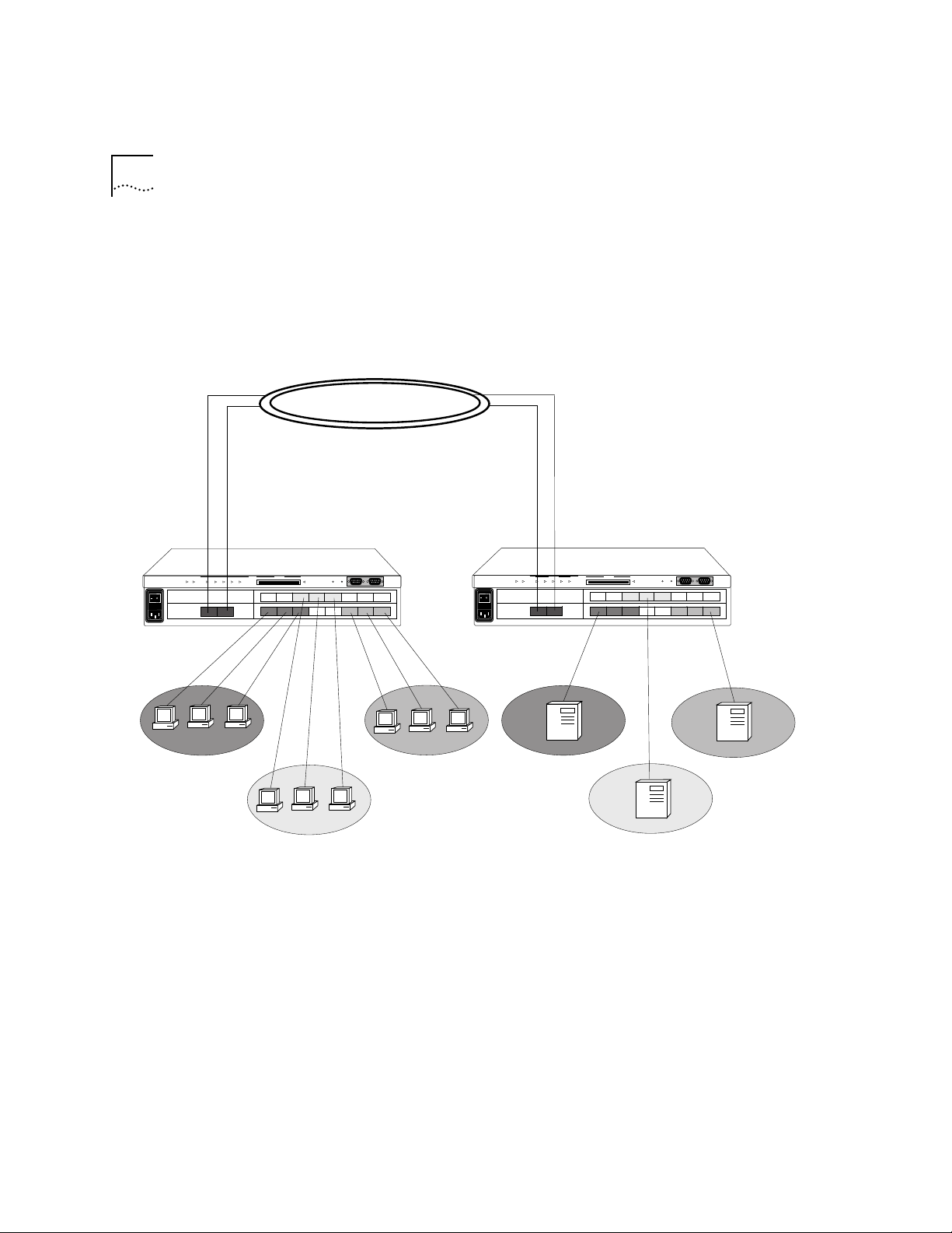
VLAN Examples Example 1
Figure 2-1 is an example of a simple configuration that contains three
protocol-sensitive VLANs (2 IP and 1 IPX) that share a high-speed FDDI link.
The end-stations and servers are on 10Mbps ports with traffic segregated by
protocol. They are only aggregated over the high-speed FDDI link. See .
IP-1
IP-2
IPX-1
LANplex 2500
IP-1
VLAN #1
Power Run
ERROR PCMCIA
Processor Power
Config Inserted
Fan Temp
IP-2
VLAN #2
FDDI
Modem Terminal
IPX-1
VLAN #3
LANplex 2500
Power Run
IP-1
IP-2
IPX-1
ERROR PCMCIA
Processor Power
Config Inserted
Fan Temp
IP-1
Server
Modem Terminal
IPX-1
Server
IP-2
Server
Figure 2-1 Example of a Protocol-Sensitive VLAN Configuration
Page 33

About VLANs 2-11
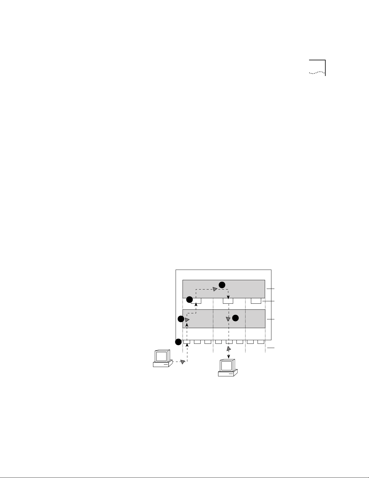
Example 2
Figure 2-2 is an example of a configuration that contains two different
protocol-sensitive VLANs (IP and IPX) with servers on separate high-speed
100BASE-T ports. The end-station clients share the same switch ports, yet
the IP and IPX traffic stays separate. See Figure 2-2.
.
= VLAN 1 (IP)
IP Server
VLAN #1
= VLAN 2 (IPX)
= VLAN 1 (IP) + VLAN 2 (IPX)
Fast Ethernet
100 BASEt
IP Server
VLAN #1, #2, and #3
LANplex 2500
Power Run
ERROR PCMCIA
Process Power
Config Inserted
Fan Temp
IP IP
Modem Terminal
IP
IPX Server
VLAN #2
Figure 2-2 A VLAN Configuration with Servers on Separate 100BASE-T ports.
IPX
IPX
IPX
Page 34

2-12 CHAPTER 2: VLANS ON THE LANPLEX® SYSTEM
Page 35

BRIDGING AND ROUTING IN THE
3
What Is Routing? Routing is the process of distributing packets over potentially dissimilar
LAN
This chapter shows how the LANplex® system operates in a subnetworked
routing environment and describes the LANplex routing methodology —
specifically, how the LANplex bridging and routing model compares with
traditional models.
networks. A router (also called a gateway) is the machine that accomplishes
this task. Routers are typically used to:
■ Connect enterprise networks together
■ Connect subnetworks (or client/server networks) to the enterprise network
Figure 3-1 shows where routers are typically used in a network.
The LANplex system performs routing that connects subnets to the
enterprise network, providing connectivity between devices within a
workgroup, depar tment, or building.
PLEX
®
SYSTEM
Page 36

3-2 CHAPTER 3: BRIDGING AND ROUTING IN THE LANPLEX® SYSTEM
Connecting
enterprise
networks
Sales
Router
LANplex in a
Subnetworked
Environment
Router
FDDI Backbone
Router
Bridge Bridge Bridge Bridge
Engineering
Figure 3-1 Traditional Architecture of a Routed Network
The LANplex system allows you to fit Ethernet switching capability into
highly subnetworked environments. When you put the LANplex system
into such a network, the system streamlines your network architecture
and easily switches traffic between and within subnets over Ethernet
and FDDI. See Figure 3-2.
Router
Connecting
subnets to the
enterprise
Marketing
Bridge
Sales
Router
FDDI backbone
LANplex®
Engineering
LANplex®
Figure 3-2 Subnetted Architecture with LANplex® Switching Hubs
Marketing
Page 37

What Is Routing? 3-3
Integrating
Bridging and
Routing
Subnet 1
The LANplex system integrates bridging and routing. Multiple switch
ports can be assigned to each subnet. See Figure 3-3. Traffic between
ports assigned to the same subnet is switched transparently using
transparent bridging or Express switching (described in the LANplex®
2500 Operation Guide). Traffic traveling to different subnets is routed
using one of the supported routing protocols.
In the following descriptions of bridging and routing on the LANplex
system, the term MAC address refers to a physical hardware address.
The term network address refers to a logical address that applies to a
specific protocol.
Subnet 4
LANplex 2500
FDDI ports
Ethernet ports
Subnet 3
Subnet 2
Figure 3-3 Multiple Ports per Subnets with the LANplex 2500 System
Because the LANplex model of bridging and routing allows several
segments to be connected to the same subnet, you can increase the
level of segmentation in your network without having to create new
subnets or assign network addresses. Instead, you can use additional
Ethernet ports to expand your existing subnets. This is in contrast to
more traditional forms of bridging and routing where, at most, one port
is connected to any subnet.
Page 38

3-4 CHAPTER 3: BRIDGING AND ROUTING IN THE LANPLEX® SYSTEM
In the traditional model, if you want to increase the level of
segmentation in your network, you must create additional subnets and
assign new network addresses to your existing hosts.
Bridging and
Routing Models
Traditional Bridging
and Routing Model
The way routing is implemented in the LANplex system differs from
how bridging and routing usually coexist in a system.
■ Traditional Bridging and Routing Model — Traditionally, bridging and
routing are peer entities; either a packet is bridged or routed. Packets
belonging to recognized protocols are routed; all others are bridged.
■ LANplex Bridging and Routing Model — In the LANplex model, the
bridge and router operate hierarchically on the LANplex system, routing
over bridging. When a packet enters the system, the system first tries to
bridge the packet. If the packet’s destination network address is not on
the same subnet, then the system routes the packet.
The bridge or router determines whether a packet should be bridged or
routed based on the protocol to which the packet belongs. If the packet
belongs to a recognized protocol, the packet is routed. O therwise, it is
bridged.
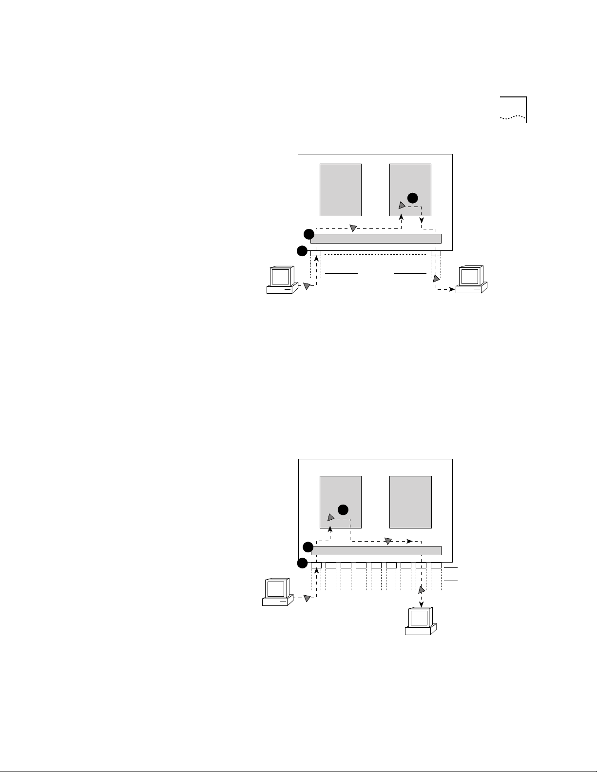
In the traditional bridging and routing model, a packet is bridged as
follows (see Figure 3-4):
1 The packet enters the bridge or router.
2 The bridge or router determines that the packet does not belong to a
recognized routing protocol, so the packet is passed to the bridge.
3 The bridge examines the destination MAC address and forwards the
packet to the port on which that address has been learned.
Page 39
Bridging and Routing Models 3-5
Router Bridge
3
2
1
Transmitting host
Router vs. Bridge ?
Interfaces (ports)
Networks
Destination host
Figure 3-4 Bridging in the Traditional Bridging and Routing Model
In the traditional bridging and routing model, a packet is routed as
follows (see Figure 3-5):
1 The packet enters the bridge or router.
2 The bridge or router determines that the packet belongs to a
recognized routing protocol, so the packet is passed to the router.
3 The router examines the destination network address and forwards the
packet to the interface (por t) connected to the destination subnet.
Router
3
Bridge
2
1
Transmitting host
Router vs. Bridge ?
Destination host
Figure 3-5 Routing in the Traditional Bridging and Routing Model
Interfaces (ports)
Networks
Page 40
3-6 CHAPTER 3: BRIDGING AND ROUTING IN THE LANPLEX® SYSTEM
LANplex Bridging
and Routing Model
The LANplex 2500 system uses the destination MAC address to
determine whether it will bridge or route a packet. Before a host system
sends a packet to another host, it compares its own network address to
the network address of the other host as follows:
■ If network addresses are on the same subnet, the packet is bridged
directly to the destination host’s address.
■ If network addresses are on different subnets, the pack et must be
routed from one subnet to the other. In this case, the host transmits the
packet to the connecting router’s MAC address.
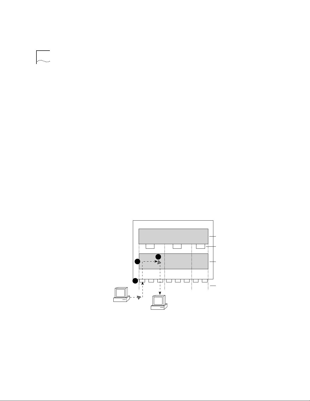
In the LANplex bridging/routing model, a packet is bridged as follows
(see Figure 3-6):
1 The packet enters the LANplex system.
2 The packet’s destination MAC address is examined by the bridging layer.
3 The destination MAC address does not correspond to the MAC address
of one of the system ports configured for routing. The bridging layer
selects a segment (port) based on the destination MAC address and
forwards the packet to that segment.
Router
1
3
2
1
123
Transmitting Host
Destination Host
2
3
Bridge
Figure 3-6 Bridging in the LANplex Bridging and Routing Model
Routing Layer
Router Interfaces
Bridging Layer
Subnets
Page 41
Bridging and Routing Models 3-7
In the LANplex bridging and routing model, a packet is routed as follows
(see Figure 3-7):
1 The packet enters the LANplex system.
2 The packet’s destination address is examined by the bridging layer.
3 The destination address corresponds to the address of one of the system
ports configured for routing (as opposed to a learned end-station address).
The packet is passed to the router interface associated with the port on
which the packet was received.
4 The routing layer:
a Selects a destination inter face based on the destination network
address.
b D etermines the MAC address of the next hop (either the destination
host or another gateway).
c Passes the packet back to the bridging layer.
5 The bridging layer then selects a segment (port) based on the destination
MAC address and forwards the packet to that segment.
4
Transmitting Host
3
1
2
1
123
2
Destination Host
Figure 3-7 Routing in the LANplex Bridging and Routing Model
Router
Bridge
5
Routing Layer
3
Router Interfaces
Bridging Layer
Subnets
Page 42

3-8 CHAPTER 3: BRIDGING AND ROUTING IN THE LANPLEX® SYSTEM
Page 43

4
ROUTING WITH IP TECHNOLOGY
This chapter gives an overview of IP routing technology, specifically
defining:
■ What IP routing involves
■ What elements are necessary for IP routers to effectively transmit packets
■ How IP routing transmission errors are detected and resolved
■ Routing with classical IP over ATM
IP Routing and
the OSI Model
An IP router, unlike a bridge, operates at the network layer of the OSI
Reference Model. That is, it routes packets by examining the network layer
address (IP address). Bridges use the data-link layer MAC addresses to make
forwarding decisions. See Figure 4-1.
OSI Reference Model
Application Layer
Presentation Layer
Session Layer
Transport Layer
Network Layer
Data-link Layer
Physical Layer
Figure 4-1 OSI Reference Model and IP Routing
IP
ARP
MAC
RIP
ICMP
Page 44

4-2 CHAPTER 4: ROUTING WITH IP TECHNOLOGY
When an IP router sends a packet, it does not know the complete path
to a destination — only the next hop. Each hop involves three steps:
■ The IP routing algorithm computes the next hop IP address, and next
router interface, using the routing table entries.
■ The Address Resolution Protocol (ARP) translates the next hop IP
address into a physical MAC address.
■ The router sends the packet over the network to the next hop.
These routing elements are described in more detail in the following
section.
Elements of IP
Routing
IP Addresses IP addresses are 32-bit addresses composed of a network part (the
IP routers use the following elements to transmit packets in a
subnetworking environment:
■ IP addresses
■ Router interfaces
■ Routing tables
■ Address Resolution Protocol (ARP)
address of the network on which the host is located) and a host part
(the address of the host on that network). See Figure 4-2. IP addresses
differ from Ethernet and FDDI MAC addresses, which are unique
hardware-configured 48-bit addresses.
IP Address
network host
The boundary between
network and host parts
depends on the
class
of IP
Figure 4-2 IP Address: Network Part and Host Part
32 bits
A central agency assigns the network part of the IP address, and the
network administrator assigns the host part. All devices connected to
the same network share the same IP address prefix (the network part of
the address).
Page 45

Elements of IP Routing 4-3
Address Classes
The boundary of the network part and the host par t depends on the
class that the central agency assigns to your network. The primary
classes of IP addresses are Class A, Class B, and Class C.
■ Class A addresses — have 8 bits for the network part and 24 bits for
the host part. Although only a few Class A networks can be created,
each can contain a very large number of hosts.
■ Class B addresses — have 16 bits for the network part and 16 bits for
the host part.
■ Class C addresses — have 24 bits for the network part and eight bits
for the host part. Each Class C network can contain only up to 254
hosts, but many such networks can be created.
The class of an IP address is designated in the high-order bits of the
network parts of the address.
Subnet Part of an IP Address
In some environments, the IP address contains a subnet part. Subnetting
allows a single Class A, B, or C network to be further subdivided
internally while still appearing as a single network to other networks.
The subnet part of the IP address is only visible to those hosts and
gateways on the subnet network.
When an IP address contains a subnet part, a subnet mask is used to
identify which bits are the subnet address and which are the host
address. A subnet mask is a 32-bit number that uses the same format
and representation as IP addresses. Each IP address bit corresponding to
a 1 in the subnet mask is in the network or subnet part of the address.
Each IP address bit corresponding to a 0 is in the host part of the IP
address. See Figure 4-3.
Page 46

4-4 CHAPTER 4: ROUTING WITH IP TECHNOLOGY
Take the IP address
IP Address
Subnet Mask
Network
Apply the subnet mask
101111111111 00000001111111111111
Result = subnet/host boundary
networ
Network
Subnet and Host
Subnet
subn
Host
Figure 4-3 How a Subnet Mask Is Applied to the IP Address
An example of an IP address that includes network, subnet, and host
parts is 158.101.230.52 with a subnet mask of 255.255.255.0. This address
is divided as follows:
■ 158.101 is the network part
■ 230 is the subnet part
■ 52 is the host part
Router Interfaces A router inter face is the connection between the router and a subnet.
In traditional routing models, the interface is the same as the port, since
only one interface can exist per port. In the LANplex system’s IP routing
model, more than one port can be connected to the same subnet.
Each router interface has an IP address and a subnet mask. This address
defines both the number of the network to which the router interface is
attached and its host number on that network. A router interface’s IP
address serves two functions:
■ The IP address is used when sending IP packets to or from the router
itself.
■ The IP address defines the network and subnet numbers of the
segment connected to that interface. See Figure 4-4.
Page 47

Elements of IP Routing 4-5
Network 2
Network 1
Interfaces
158.101.1.2 158.101.2.2
12
158.101.2.1
Router
Interface 1
IP Address
158.101.1.1
3
Interface
158.101.3.2
158.101.3.1
Network 3
Figure 4-4 Router Interfaces in the LANplex System
Routing Table A routing table allows a router or host to determine how to send a
packet toward the packet’s ultimate destination. The routing table
contains an entry for every destination network, subnet, or host to
which the router or host is capable of forwarding packets. A router or
host uses the routing table when the destination IP address of the
packet it is sending is not on a network or subnet to which it is directly
connected. The routing table provides the IP address of a router that
can forward the packet toward its destination.
The routing table consists of the following elements:
■ Destination IP Address — the destination network, subnet, or host
■ Subnet Mask — the subnet mask corresponding to the destination IP
address
■ Metric — a measure of the “distance” to the destination. In the Routing
Information Protocol (RIP), the metric is the number of hops.
■ Gateway — the IP address of the next hop router (the IP address of the
interface through which the packet travels)
■ Interface — the interface number through which a packet must travel
to reach that router
Figure 4-5 shows the routing table of the router in Figure 4-4.
Page 48

4-6 CHAPTER 4: ROUTING WITH IP TECHNOLOGY
Routing T able
Destination IP Address Interface
158.101.1.1
158.101.2.1
158.101.3.1
default route
Subnet Mask
255.255.255.0
255.255.255.0
255.255.255.0
255.255.255.0
Metric
1
1
1
1
Gateway
158.101.1.2
158.101.2.2
158.101.3.2
158.101.1.2
1
2
3
1
Figure 4-5 Example of a Routing Table in the LANplex Routing Model
Routing table information is generated and updated in either of the
following ways:
■ Statically — You manually enter routes, which do not change until
you change them (that is, they will not time out).
■ Dynamically — The router uses a routing protocol, such as RIP, to
exchange information. Routes are recalculated at regular intervals.
Static Routes
A static route is one that you manually configure in the routing table.
Static routes are useful in environments where no routing protocol is
used or where you want to override some of the routes generated with
a routing protocol. Because static routes do not automatically change in
response to network topology changes, you should manually configure
only a small number of reasonably stable routes.
Dynamic Routes Using RIP
Automated methods of configuring routes help you keep up with a
changing network environment, allowing routes to be reconfigured
quickly and reliably. Interior Gateway Protocols (IGP), which operate
within networks, provide this automated method. The LANplex system
uses the Routing Information Protocol (RIP), one of the most widely
used IGPs, to configure its routing tables dynamically.
RIP operates in terms of active and passive devices. The active devices,
usually routers, broadcast their RIP messages to all devices in a network
or subnet; they update their own routing tables when they receive a RIP
message. The passive devices, usually hosts, listen for RIP messages and
update their routing tables; they do not send RIP messages.
Page 49

Elements of IP Routing 4-7
An active router sends a RIP message every 30 seconds. This message
contains both the IP address and a metric (the distance to the
destination from that router) for each destination. In RIP, each router
that a packet must travel through to reach a destination equals one
hop.
Default Route
In addition to the routes to specific destinations, the routing table may
contain an entry called the default route. The router uses the default
route to forward packets that do not match any other routing table
entry. A default route is often used in place of routes to numerous
destinations all having the same gateway IP address and interface
number. The default route can be configured statically, or it can be
learned dynamically using RIP.
Address Resolution
Protocol (ARP)
ARP is a low-level protocol used to locate the MAC address corresponding to a given IP address. This protocol allows a host or router to make
its routing decisions using IP addresses while it uses MAC addresses to
forward packets from one hop to the next.
Once the host or router knows the IP address of the next hop to the
destination, the host or router must translate that IP address into a MAC
address before the packet can be sent. To do this translation, the host or
router first looks in its ARP cache, a table of IP addresses with their corresponding MAC addresses. Each device par ticipating in IP routing
maintains an ARP cache. See Figure 4-6.
ARP Cache
IP Address MAC Address
158.101.1.1
158.101.2.1
Figure 4-6 Example of an ARP Cache
00308e3d0042
0080232b00ab
If the IP address does not have a corresponding MAC address listed, the
host or router broadcasts an ARP request packet to all the devices on the
network. The ARP request contains information about the hardware and
Page 50

4-8 CHAPTER 4: ROUTING WITH IP TECHNOLOGY
protocol. The two key elements of the ARP request are the target and
source addresses for both the hardware (MAC addresses) and the
protocol (IP addresses). See Figure 4-7.
ARP Request
00802322b00ad
158.101.2.1
?
158.101.2.15
Source hardware address
Source protocol address
Target hardware address
Target protocol address
Figure 4-7 Example of an ARP Request Packet
When the devices on the network receive this packet, they examine it,
and if their address is not the target protocol address, they discard the
packet. When a device receives the packet and confirms that its IP
address matches the target protocol address, this device places its MAC
address in the target hardware address field and sends the packet back
to the source hardware address. When the originating host or router
receives the ARP reply, it places the new MAC address in its ARP cache
next to the corresponding IP address. See Figure 4-8.
ARP Cache
IP Address MAC Address
158.101.1.1
158.101.2.1
158.101.3.1
00308e3d0042
0080232b00ab
0134650f3000
Figure 4-8 Example of ARP Cache Updated with ARP Reply
Once the MAC address is known, the host or router can send the packet
directly to the next hop.
Page 51

IP Routing Transmission Errors 4-9
IP Routing
Transmission
Errors
Because each router only knows about the next hop, it is not aware of
problems that might be further “down the road” toward the destination.
Destinations can be unreachable if:
■ Hardware is temporarily out of service
■ You inadvertently specified a nonexistent destination address
■ The router does not have a route to the destination network
To help routers and hosts know of problems in packet transmission, an
error-reporting mechanism called Internet Control Message Protocol
(ICMP) provides error reporting back to the source when routing
problems arise. ICMP allows you to determine whether a delivery
failure resulted from a local or a remote malfunction.
ICMP does the following:
■ Tests the reachability of nodes (ICMP Echo Request and ICMP Echo Reply)
A host or gateway sends an ICMP echo request to a specified
destination. If the destination receives the echo request, it sends an
ICMP echo reply back to the original sender. This process tests whether
the destination is reachable and responding and verifies that the major
pieces of the transport system work. The ping command is one
frequently used way to invoke this process.
■ Creates more efficient routing (ICMP Redirect)
Often the host route configuration specifies the minimal possible
routing information needed to communicate (for example, the address
of a single router). The host relies on routers to update its routing table.
In the process of routing packets, a router may detect a host not using
the best route. The router then sends the host an ICMP redirect,
requesting that the host use a different gateway when sending packets
to that destination. The next time the host sends a packet to that same
destination, it uses the new route.
■ Informs sources that a packet has exceeded its allocated time to exist
within the network (ICMP Time Exceeded)
Page 52

4-10 CHAPTER 4: ROUTING WITH IP TECHNOLOGY
Routing with
Classical IP over
ATM
LANPlex Extended Switching software supports classical IP routing over ATM
ARP in an ATM network. Classical IP over ATM uses Logical IP Subnets (LISs)
to forward packets within the network environment.
See the LANplex® 2500 Operation Guide for detailed information about the
ATM protocol architecture. S ee the LANplex® 2500 Administration Console
User Guide for information about how to configure ATM ports.
About Logical IP
Subnets (LISs)
An LIS is a group of IP nodes that belong to the same subnet, and which are
directly connected to a single ATM network. When you add a node to a LIS
through the Administration Console IP interface menu, you define its IP
address, subnet mask, and the address an ATM ARP server that supports it.
ATM ARP Servers An ATM ARP server maintains a table of IP addresses and their
corresponding ATM addresses and circuit information. To forward IP
packets over an ATM interface, the network node learns the ATM address for
the corresponding IP address from the ATM ARP server.
Each ATM ARP server supports a single LIS. You can associated two or more
LISs with the same ATM network, but each LIS operates independently of
other LISs on the network.
Several types of network nodes can function as ATM ARP servers:
■ Any LANplex system with revision 8.1.0 or later of Extended Switching
software
■ An ATM switch
■ A UNIX® workstation
The following sequence describes how the ATM ARP server learns and
stores information about the IP and ATM addresses of nodes in the network.
■ A node establishes a connection to the ATM ARP server
■ The ATM ARP server sends an inverse ATM ARP request to the node,
requesting its IP and ATM address
■ When the node returns this information, the ATM ARP server stores, or
caches, it in the ATM ARP server table.
Page 53

IP Routing References 4-11
Forwarding to Nodes within an LIS
Nodes can forward packets directly to other nodes in the same LIS. To
forward a packet within the same LIS, the sending node requests a
translation from the destination IP address to the corresponding ATM
address from the ATM ARP server.
■ If the address is known to the server, the server returns a message with this
address
■ If the address is not known to the server, the server returns a message to
advise the sending node that the packet is discarded.
When the server returns a destination address, the sending node uses this
learned address to create a virtual circuit ( VC) and to forward this and all
subsequent packets to the destination address. The sending node adds this
VC to its ATM ARP cache.
IP Routing
References
Comer, Douglas E. Internetworking with TCP/IP. Volume I: Principles, Protocols,
and Architecture. Englewood Cliffs, New Jersey: Prentice Hall, Inc., 1991.
Perlman, Radia. Interconnections: Bridges and Routers. Reading,
Massachusetts: Addison-Wesley Publishing Company, Inc., 1992.
Sterns, Richard. TCP/IP Illustrated. Volume 1: The Protocols. Reading,
Massachusetts: Addison-Wesley Professional Computing Services, 1992.
RFC 791. Internet Protocol Specification.
RFC 792. Internet Control Message Protocol Specification.
RFC 1009. Requirements for Internet Gateways.
RFC 1042. A Standard for the Transmission of IP Datagrams over IEEE 802
Networks.
RFC 1058. Routing Information Protocol.
RFC 1122. Requirements for Internet Hosts.
RFC 1577. Classical IP over ATM.
Page 54

4-12 CHAPTER 4: ROUTING WITH IP TECHNOLOGY
Page 55

5
ROUTING WITH IP MULTICAST
This chapter describes the IP multicast routing implementation on the
LANplex® system.
About IP
Multicast Routing
IP multicast routing is an extension of the Internet Protocol. Multicast
routing allows a router or switch to send packets to a specific group of
hosts without using broadcasts or multiple unicast transmissions. This group
can include members that reside on the local LAN, members that reside on
different sites within a private network, or members that are scattered
throughout the Internet. Mulitcast routing achieves this functionality
without loops or excess transmissions.
IP Multicast support within the LANplex system has two main components:
■ Internet Group Management Protocol (IGMP)
■ Distance Vector Multicast Routing Protocol (DVMRP)
This chapter describes these two protocols as well as the algorithms that
the LANplex system uses for multicast routing.
IGMP The LANplex system is capable of dynamic multicast filtering based on the
Internet Group Management Protocol (IGMP). This protocol ensures that
multicast packets are flooded only to the appropriate ports within a routing
interface.
IGMP tracks end-station group membership within a multicast group.
Membership in a group is dynamic, and hosts are allowed to be a member
of more than one group at a time. Broadcast domains are maintained by
avoiding propagation of multicast broadcasts to the entire subnet by
confining them within the group (IGMP “snooping”).
Page 56

5-2 CHAPTER 5: ROUTING WITH IP MULTICAST
DVMRP The Distance Vector Multicast Routing Protocol (DVMRP) establishes
the multicast delivery path over a series of routing devices. DVMRP is a
simple distance vector routing protocol, similar to the IP Routing
Information Protocol (RIP). Multicast routers exchange distance vector
updates that contain lists of destinations as well as the distance in hops
to each destination. They maintain this information in a routing table.
DVMRP is the current routing protocol used on the Internet Multicast
Backbone (MBONE). Full support of DVMRP allows the LANplex system
to fully establish the delivery path without requiring a direct connection
to a multicast router.
The MBONE The MBONE is an experimental “Multicast Backbone” network that exists
on the Internet. Users can test multicast applications and technology on
the MBONE without waiting for Internet multicast standards to be set.
You can gain access to the MBONE through any Internet service
provider.
The MBONE routers forward mulitcast packets over an interface or over
a multicast tunnel only if the Time-To-Live (T TL) value present in the
packet is larger than the tunnel’s threshold. (See the section “Multicast
Tunnels” on page 6 for more information about tunnels.)
LANplex 2500 systems at revisions earlier than 8.0 support up to 16 IP
multicast tunnels or routing interfaces when connected to the MBONE
network. LANplex 2500 systems at revision 8.0 or later can support up to
32 IP multicast tunnels or routing interfaces when connected to the
MBONE.
Page 57

Multicast Routing Algorithms 5-3
Multicast Routing
Algorithms
The LANplex system uses three algorithms that support multicast
routing:
■ Flooding
■ Spanning Trees
■ Reverse Path Forwarding
Flooding Several types of flooding algorithms exist, but they all share the same
general principles: a node in the network receives a packet that was
sent to a multicast destination. The node determines whether the
packet is an original that it has not seen before or a duplicate of a
packet that it has seen before. If the packet is an original, the node
forwards the packet on all interfaces except the incoming inter face. If
the packet is a duplicate, the node discards it.
The flooding algorithm is useful in situations where the most important
requirement for the network is robustness. I t does not depend on any
kind of routing tables. Destinations will receive packets as long as at
least one path to them exists and no errors occur during transmission.
Spanning Trees The Spanning Tree algorithm detects loops and logically blocks
redundant paths in the network. The paths form a loopless graph, or
tree, spanning all the nodes in the network. A port in the blocking state
does not forward or receive data packets.
After the algorithm eliminates extra paths, the network configuration
stabilizes. When one or more of the paths in the stable topology fail, the
protocol automatically recognizes the changed configuration and
activates redundant links. This strategy ensures that all nodes remain
connected.
Page 58
5-4 CHAPTER 5: ROUTING WITH IP MULTICAST
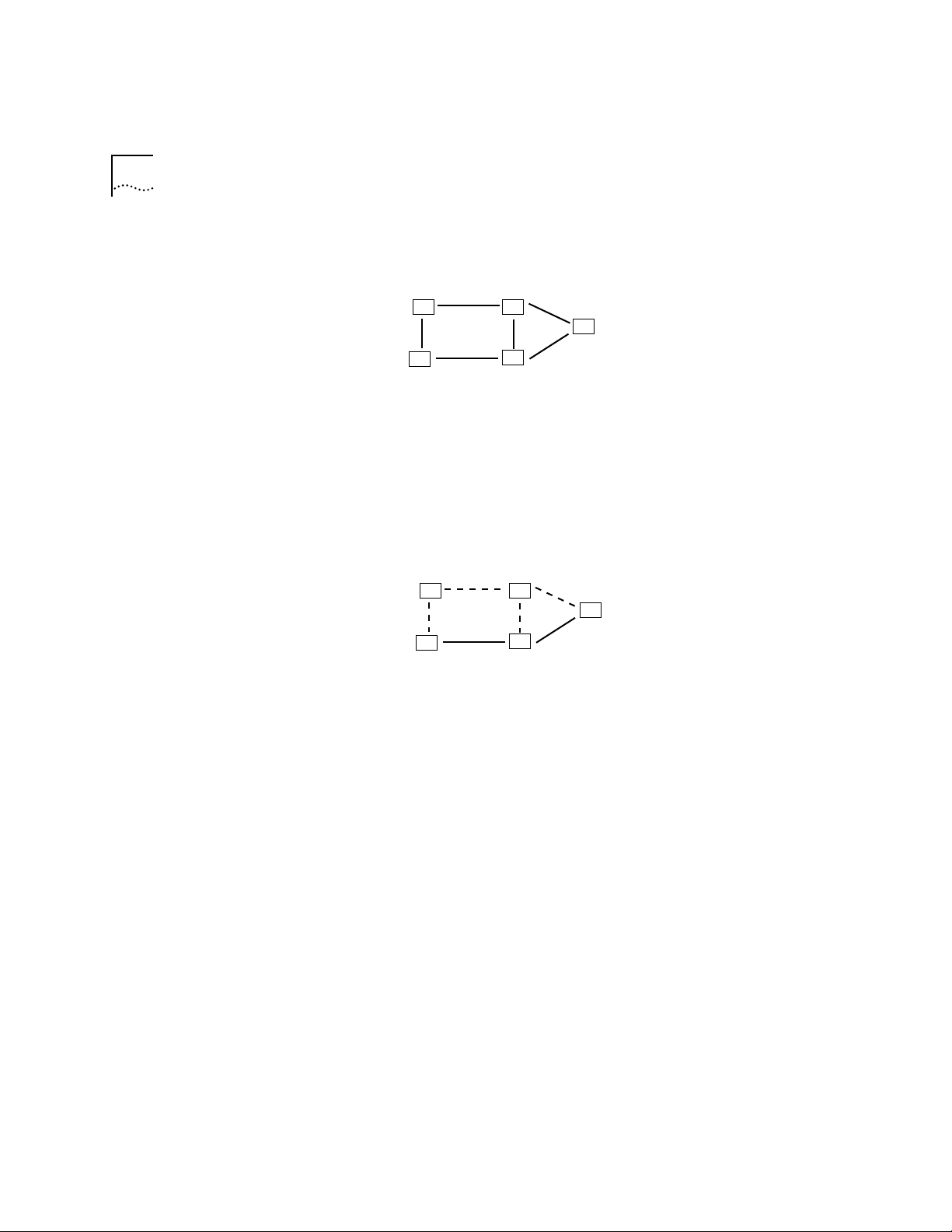
Figure 5-1 shows a simple network with five links.
1
A
3
D
Figure 5-1 Simple Network Implemented Without Using Spanning Tree
4
6
2
B
C
E
5
A spanning tree for this network consists of links 1, 2, 3, and 4. See
Figure 5-2.
1
A
3
D
Figure 5-2 Spanning Tree Algorithm Implemented to Block Redundant Paths
4
6
2
B
C
E
5
Reverse Path
Forwarding
Reverse path forwarding (RPF) is the multicast algorithm in use on the
MBONE network. RPF is designed to avoid duplicate paths on
multi-access links. It uses a routing table to compute a logical spanning
tree for each network source. The RPF algorithm has these basic steps:
1 When the system receives a multicast packet, the algorithm notes the
source network of the packet and the interface on the LANplex system
that received the packet.
2 If the interface belongs to the shortest path towards the source
network, then the system forwards the packet to all interfaces except
the interface on which the packet was received.
3 If the condition in Step 2 is false, the system drops the packet.
Page 59

Multicast Interfaces 5-5
Pruning Pruning is a method used in the RPF algorithm to forward packets to a
spanning tree only if group members exist in the tree. This method results
in fewer spanning trees, but it requires dynamic updates to the routing
table.
Nodes that are at the border of the network and have no point beyond
them in the RPF spanning tree are called leaf nodes. Leaf nodes all receive
the first multicast packet. If a group member is attached to the leaf node,
the node continues to accept packets. If no group member is attached to
the leaf node, the node sends back a “prune message” to the router that
sent the packet. The message tells the router to send no further packets to
this group. In the LANplex system, the Administration Console IP multicast
CacheDisplay includes information about when pruning will occur on the
spanning tree.
Multicast
Interfaces
DVMRP Metric Value The DVMRP metric value determines the cost of a multicast interface. The
Time-To-Live (TTL)
Threshold
Multicast interfaces on the LANplex system have several characteristics
which are described in this section:
higher the cost, the slower the link. The default value is 1.
This TTL threshold determines whether the interface will forward multicast
packets to other switches and routers in the subnet. If the interface TTL is
greater than the packet TTL, then the interface does not forward the packet.
The default value is one 1, which means that the interface forwards most
packets.
Page 60

5-6 CHAPTER 5: ROUTING WITH IP MULTICAST
Rate Limit The rate limit determines how many multicast packets can travel over the
interface in kilobytes-per-second. The LANplex system drops multicast traffic
that travels faster than this rate. The default is set to 0, which implies no rate
limit is set. In all other instances, the lower the rate limit, the more limited
the traffic over the interface.
Multicast Tunnels Multicast tunnels are logical connections between two multicast routers
through one or more unicast routers. The multicast router at the local
endpoint of the tunnel encapsulates multicast packets in a format that
unicast routers can interpret and forward. The multicast router at the
remote endpoint decapsulates the packets into their multicast format.
Tunnels are virtual links through the unicast IP network.
Multicast tunnels have characteristics similar to those of a multicast
interface: a DVMRP metric value, a TTL threshold, and a rate limit. When you
define a multicast tunnel, you also specify the destination address of the
remote multicast router that is the remote endpoint of the tunnel.
Page 61

6
ROUTING WITH IPX
This chapter provides an overview of IPX routing, including:
■ What part IPX plays in the NetWare environment
■ How IPX works
■ What elements are necessary for IPX routers to transmit packets effectively
IPX Routing in
the NetWare
®
Environment
The NetWare® network operating system was developed and introduced to
the market by Novell, Inc. in the early 1980s. Much of the NetWare
networking technology was derived from Xerox Network System (XNS)
networking system developed by Xerox Corporation.
The NetWare operating system is based on a client/server architecture
where clients request certain services from ser vers such as file access and
printer access. As a network operating system environment, the NetWare
operating system specifies the upper five layers of the OSI reference model.
It provides file and printer sharing and supports various applications such as
electronic mail and database access.
Figure 6-1 illustrates a simplified view of NetWare’s better-known protocols
and their relationship to the OSI reference model.
TM
, a
Page 62
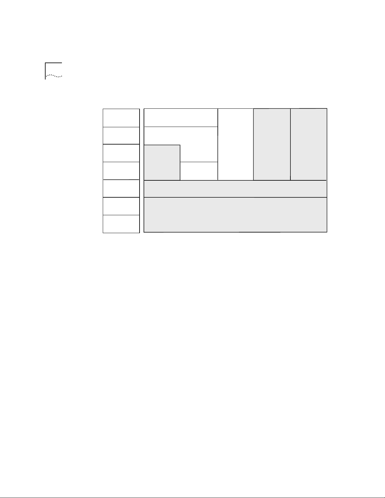
6-2 CHAPTER 6: ROUTING WITH IPX
Layers in the
OSI reference model
Application
Presentation
Session
Transport
Network
Data Link
Physical
NetBIOS™
Appplications
NetWare®
Shell
(Client)
SPX
NetWare
NetWare®
Control
Protocol
(NCP)
IPX
Media Access Protocols
(Ethernet, FDDI)
Service
Advertising
Protocol
(SAP)
Figure 6-1 NetWare Protocols and the OSI Reference Model
The LANplex system uses the following protocols for routing in a Netware
environment:
■ Internet Packet Exchange (IPX)
Routing
Information
Protocol
(RIP)
Internet Packet
Exchange (IPX)
■ Routing Information Protocol (RIP)
■ Service Advertisement Protocol (SAP)
IPX is the primary protocol used for routing in a netware environment. This
datagram, connectionless protocol does not require an acknowledgment for
each packet sent. Any packet acknowledgment, or connection control, must
be provided by protocols above IPX.
IPX defines internetwork and intranode addressing schemes. IPX
internetwork addressing is based on network numbers that are assigned to
each interface in an IPX network. IPX intranode addressing is in the form of
socket numbers. Since several processes are normally operating within a
node, socket numbers provide a type of mail slot so that each process can
distinguish itself to IPX.
Page 63

IPX Routing in the NetWare® Environment 6-3
Routing
Information
Protocol (RIP)
Service Advertising
Protocol (SAP)
RIP allows the exchange of routing information on a NetWare network. IPX
routers use RIP to dynamically create and maintain their routing tables.
RIP allows one router to exchange routing information with a neighboring
router. As a router becomes aware of any changes in the network layout,
it broadcasts this information to any neighboring routers. IPX routers also
send periodic RIP broadcast packets containing all routing information
known to the router. These broadcasts synchronize all routers on the
network and age those networks that might become inaccessible if a router
becomes disconnected from the network abnormally.
SAP provides routers and servers that contain SAP agents with a means of
exchanging network service information.
Through SAP, servers advertise their ser vices and addresses. Routers gather
this information and share it with other routers. This strategy allows routers
to dynamically create and maintain a database (server table) of network
service information. Clients on the network can determine what services are
available and obtain the network address of the nodes (servers) where they
can access those services. Clients require this information to initiate a
session with a file server.
SAP allows one router to exchange information with a neighboring SAP
agent. As a router’s SAP agent becomes aware of any change in the
network server layout, it immediately broadcasts this information to any
neighboring SAP agents. The router also periodically sends SAP broadcast
packets containing all server information known to the SAP agent. These
broadcasts synchronize all servers on the network and age those servers
that might become inaccessible because of any abnormal shut down of the
router or server.
Page 64

6-4 CHAPTER 6: ROUTING WITH IPX
How IPX Routing
Works
A router operates at the network layer of the OSI Reference Model. This
means that it receives its instructions to route packets from one segment to
another from a network-layer protocol. IPX, with the help of RIP, performs
these network layer tasks. These tasks include addressing, routing, and
switching information packets to move single packets from one location to
another. This section first describes the information included in an IPX
packet that helps it get delivered and then it describes the IPX packet
delivery process.
IPX Packet Format The IPX packet format consists of two parts: a 30-byte header and a data
portion. The network, node, and socket address for both the destination and
source are held within the packet’s IPX header.
Figure 6-2 shows the IPX packet format.
Checksum
Packet Length
Transport Control
(1 byte)
Destination Network
(2 bytes)
(2 bytes)
Packet Type
(1 byte)
(4 bytes)
Destination Node
Destination Socket
Source Network
Source Node
Source Socket
Upper-layer Data
(6 bytes)
(2 bytes)
(4 bytes)
(6 bytes)
(2 bytes)
Figure 6-2 IPX Packet Format
Page 65

How IPX Routing Works 6-5
The packet format consists of the following elements:
■ Checksum — The IPX packet begins with a 16-bit checksum field that is set
to 1s.
■ Packet Length — This 16-bit field contains the length, in bytes, of the
complete network packet. This field includes both the IPX header and the
data. The IPX length must be at least 30 bytes.
■ Transport Control — This 1-byte field indicates how many routers a packet
has passed through on its way to its destination. Packets are discarded
when this value reaches 16. A sending node always sets this field to 0 when
building an IPX packet.
■ Packet Type — This 1-byte field specifies the upper-layer protocol that will
receive the packet’s information.
■ Destination Network — This 4-byte field provides the destination node’s
network number. When a sending node sets this field to zero, the
destination node is assumed to be on the same local segment as the
sending node.
■ Destination Node — This 6-byte field contains the physical address of the
destination node.
■ Destination Socket — This 2-byte field contains the socket address of the
packet’s destination process.
■ Source Network — This 4-byte field provides the source node’s network
number. If a sending node sets this field to 0, it means the source’s local
network is unknown.
■ Source Node — This 6-byte field contains the physical address of the
source node. Broadcast addresses are not allowed.
■ Source Socket — This 2-byte field contains the socket address of the
process that transmitted the packet.
■ Upper-layer Data — The data field contains information for the upper-layer
processes.
Page 66
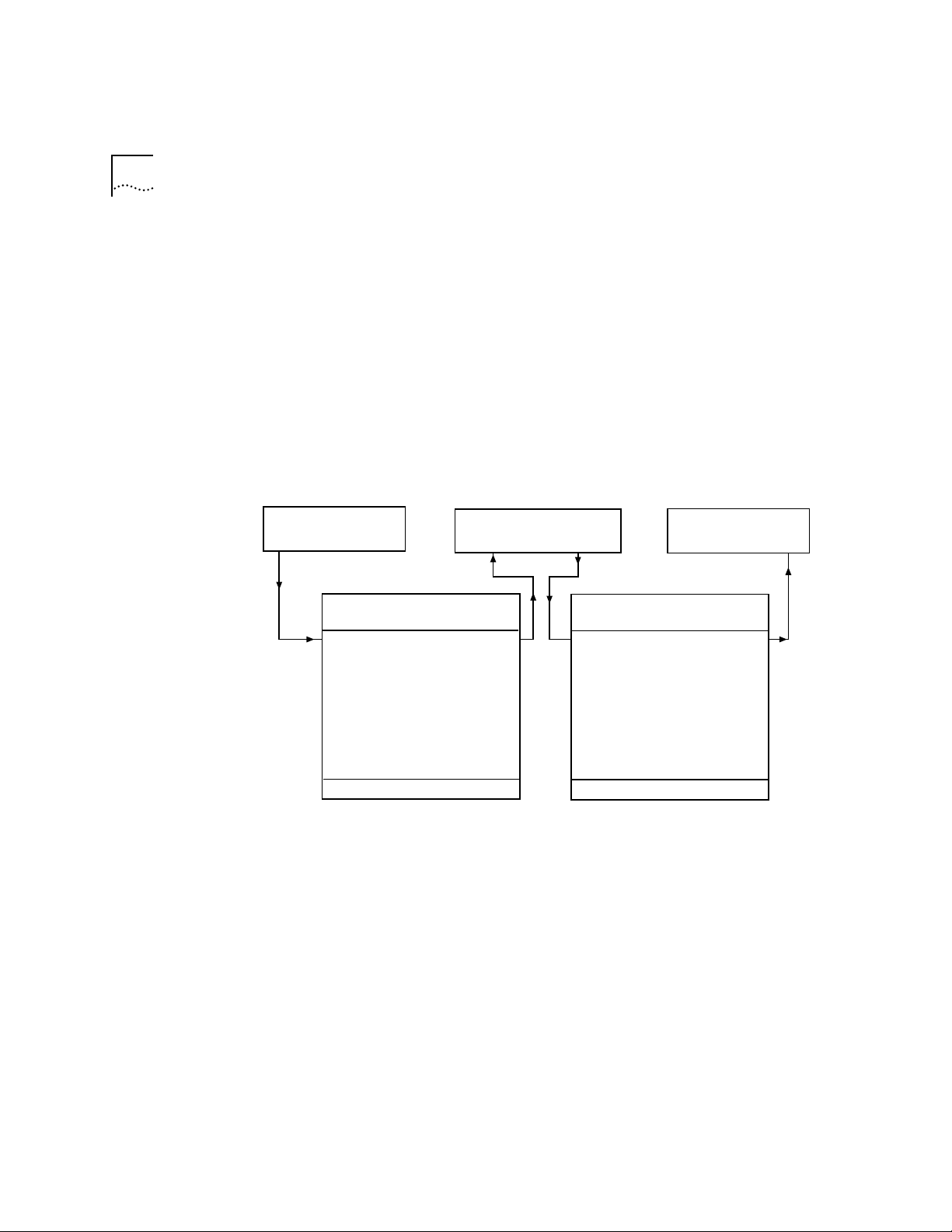
6-6 CHAPTER 6: ROUTING WITH IPX
IPX Packet Delivery On a NetWare network, the successful delivery of a packet depends both on
the proper addressing of the packet and on the internetwork configuration.
Packet addressing is handled in the packet’s Media Access Control (MAC)
protocol header and IPX header address fields.
To send a packet to another node, the sending node must know the
complete internetwork address including the network, node, and socket of
the destination node. Once the sending node has the destination node’s
address, it can proceed with addressing the packet. However, the way the
MAC header of that packet is addressed depends on whether the sending
and destination nodes are separated by a router. See Figure 6-3.
Sending Node Router Destination Node
Network = 000000AA
Node = 000000000001
Socket = 4003
Node Node
000000000020 000000000021
Network = 000000BB
Node = 000000000003
Socket = 0451
MAC Header
Destination Node = 000000000020
Source Node = 000000000001
IPX Header
Checksum = FFFF
Packet Length = 011E
Tranport Control = 00
Packet Type = 11
Dest Network = 000000BB
Dest Node = 000000000003
Dest Socket = 0451
Source Network = 000000AA
Source Node = 000000000001
Source Socket = 4003
Data
MAC Header
Destination Node = 000000000003
Source Node = 000000000021
IPX Header
Checksum = FFFF
Packet Length = 011E
Tranport Control = 01
Packet Type = 11
Dest Network = 000000BB
Dest Node = 000000000003
Dest Socket = 0451
Source Network = 000000AA
Source Node = 000000000001
Source Socket = 4003
Data
Figure 6-3 IPX Packet Routing
Sending Node’s Responsibility
When a node needs to send information to another node with the same
network number, the sending node can simply address and send packets
directly to the destination node. However, if the sending and receiving
nodes have different network numbers, the sending node must find a
router on its own network segment that can forward packets to the
destination node’s network segment.
Page 67

How IPX Routing Works 6-7
To find this router, the sending node broadcasts a RIP packet requesting the
best route to the destination node’s network number. The router residing on
the sending node’s segment with the shortest path to the destination
segment responds to the RIP request. The router’s response includes its
network and node address in the IPX header. If the sending node is a router
rather than a workstation, the router can get this information from its
internal routing tables and need not send a RIP request.
Once the sending node knows the router’s node address, it can send
packets to the destination node.
Router’s Responsibility
When a router receives an IPX packet, it handles the packet in one of two
ways:
■ If the packet is destined for a network number to which the router is
directly connected, the router performs the following tasks:
■ Places the destination node address from the IPX header in the
destination address field of the MAC header.
■ Places its own node address in the source address field of the MAC
header.
■ Increments the Transport Control field of the IPX header and transmits
the packet on the destination node segment.
■ If the packet is destined for a network number to which the router is not
directly connected, the router sends the packet to the next router along the
path to the destination node as follows:
■ The router looks up the node address (in the routing information table)
of the next router and places the address in the destination address field
of the packet’s MAC header. For more information on routing tables, see
the next section.
■ The router places its own node address in the source address field of the
packet’s MAC header.
■ The router increments the Transport Control field in the IPX header and
sends the packet to the next router.
Page 68

6-8 CHAPTER 6: ROUTING WITH IPX
The Elements of
IPX Routing
IPX routers use the following elements to transmit packets over an
intranetwork:
■ Router interfaces
■ Routing tables
■ Service Advertising Protocol (SAP)
Router Interfaces A router inter face is the connection between the router and the network
number (address). In traditional routing models, the inter face would be the
same as the port, because only one interface can exist per port.
In the LANplex system’s IPX routing, more than one por t can be connected
to the network number. Therefore, the router interface is the relationship
between the ports and the network number (address) in your IPX network.
Each router interface has a network address. This address defines the
network number to which the router interface is attached. The router
interface’s IPX address serves two functions:
■ It is used when sending IPX packets to or from the router itself.
■ It defines the network number of the segment connected to that inter face.
Routing Tables A routing table holds information about all the network segments. It allows
a router to send a packet toward its ultimate destination using the best
possible route. The routing information table contains an entry for every
network number that the router currently knows exists. A router uses the
routing information table when the destination network number of the
packet it is sending is not on a network to which it is directly connected.
The routing information table provides the immediate address of a
forwarding router that can forward the packet toward its destination.
The routing table consists of the following elements:
■ Interface — Identifies the number of the router’s interface that will be used
to reach the specific network segment.
■ Address — Identifies the addresses for segments that the router currently
knows exists.
Page 69

The Elements of IPX Routing 6-9
■ Hops to Network — Provides the number of routers that must be crossed
to reach the network segment.
■ Ticks to Network — Provides an estimate of the time necessary to reach
the destination segment.
■ Node — The node address of the router that can forward packets to each
segment. When set to all zeroes, the route is directly connected.
■ Aging Timer — The time since the network’s last update.
Figure 6-4 shows an example of a typical routing information table.
Routing Table
Interface Address Hops Ticks Node Age
1 1 1 1 00-00-00-00-00-00 0
2 45469f30 1 1 00-00-00-00-00-00 0
2 45469f33 2 3 08-00-17-04-33-45 40
Figure 6-4 Routing Table Example
Generating Routing Table Information
The routing information table is generated and updated as follows:
■ Statically — You manually enter routes. They do not change until you
change them (they do not time out).
■ Dynamically — The router uses RIP to exchange information with other
routers. Routes are recalculated at regular intervals.
Static Routes. A static route is one you manually configure in the routing
table. Static routes are useful in environments where no routing protocol is
used or where you want to override some of the routes generated with a
routing protocol. Because static routes do not automatically change in
response to network topology changes, you should manually configure only
a small number of reasonably stable routes.
Dynamic Routes Using RIP. Automated methods of learning routes help
you keep up with a changing network environment, allowing routes to be
reconfigured quickly and reliably. Interior Gateway Protocols (IGP), which
operate within intranetworks, provide this automated method. The LANplex
Page 70

6-10 CHAPTER 6: ROUTING WITH IPX
system uses RIP (one of the most widely used IGPs), to dynamically build its
routing tables.
RIP operates in terms of active and passive devices. The active devices,
usually routers, broadcast their RIP messages to all devices in a network;
they update their own routing tables when they receive a RIP message. The
passive devices, usually hosts, listen for RIP messages and update their
routing tables; they do not send RIP messages.
An active router sends a RIP message every 60 seconds. This message
contains both the network number for each destination network and the
number of hops to reach it. In RIP, each router that a packet must travel
through to reach a destination equals one hop.
Selecting the Best Route
Large networks have multiple routes to a single network. The routers use
these criteria to select the best “route” to a network when choosing
between alternate routes:
Service Advertising
Protocol
■ Select the route that requires the lowest number of ticks.
■ If multiple routes exist with an equal number of ticks, select the route that
also has the lowest number of hops.
■ If multiple routes exist with both ticks and hops equal, choose any of the
routes as the “best ” route.
The Service Advertising Protocol (SAP) allows servers (for example, file
servers, print servers, and gateway servers) to advertise their addresses and
services. Through the use of SAP, adding and removing services on an
internetwork becomes dynamic. As servers are booted up, they advertise
their services using SAP. When they are brought down, they use SAP to
indicate that their services are no longer available.
Internetwork Service Information
Using SAP, routers create and maintain a database of internetwork service
information. Clients on use this data to determine what services are
available on the network and to obtain the internetwork address of the
nodes (servers) where they can access desired services.
Page 71

The Elements of IPX Routing 6-11
A workstation must first know a server’s network address before it can
initiate a session with a file server.
SAP Packet Structure
SAP uses IPX and the medium-access protocols for its transport. The packet
structure allows the following functions:
■ A workstation request for the name and address of the nearest server of a
certain type
■ A router request for the names and addresses of all the servers or of all the
servers of a certain type on the internet work
■ A response to a workstation or a router request
■ Periodic broadcasts by servers and routers
■ Changed server information broadcasts
Figure 6-5 provides an overview of the SAP packet structure. Note that the
packet structure is encapsulated within the data area of IPX.
IPX Packet Format
IPX Header (30 bytes)
Packet Type = 4
Socket = 452h
Data
SAP Packet Structure
Operation (2 bytes)
Server Entry (1) (64 bytes)
.
.
.
Server Entry (n) (64 bytes)
(n <= 7)
Figure 6-5 SAP Packet Structure
Server Entry Structure
Service Type (2 bytes)
Server Name (48 bytes)
Network Address (4 bytes)
Node Address (6 bytes)
Socket Address (2 bytes)
Hops to Server (2 bytes)
Page 72

6-12 CHAPTER 6: ROUTING WITH IPX
A SAP packet consists of the following fields:
■ Operation — This field indicates the type of operation the SAP packet
performs. It can be set to one of the following values:
1=Request
2=Response
3=Get Nearest Server Request
4=Get Nearest Server Response
■ Server Entry — Each 64-byte ser ver entry includes information about a
particular server. It consists of the following fields:
■ Service Type — This 2-byte field identifies the type of service the ser ver
provides.
Although IPX routers use SAP, routers typically do not act as servers and
require no Service Type assignment.
■ Server Name — This field contains the 48-byte character string name
that is assigned to a server. The server name, in combination with the
service type, uniquely identifies a server on an internetwork.
■ Network Address — This 4-byte field contains the server’s network
address.
■ Node Address — This 6-byte field contains the server’s node address.
■ Socket Address — This 2-byte field contains the socket number that
the server uses to receive service requests.
■ Hops to Server — This 2-byte field indicates the number of
intermediate networks that must be passed through to reach the server
associated with this field entry. Each time the packet passes through an
intermediate network, the field is incremented by 1.
By using SAP, servers can advertise their services and addresses. The
information that these servers broadcast is not directly used by clients;
rather it is collected by a SAP agent within each router on the server’s
segment. The SAP agents store this information in a server information
table. If the agents reside within a server, the information is also stored in
their server’s bindery. The clients can then contact the nearest router or file
server SAP agent for server information.
Page 73

The Elements of IPX Routing 6-13
The SAP broadcasts that servers and routers send are local and, therefore,
only received by SAP agents on their connected segments. However, SAP
agents periodically broadcast their server information so that all SAP agents
on the internetwork have information about all servers that are active on
the internetwork.
Server Information Table
A server information table holds information about all the servers on the
internetwork. SAP agents use this table to store information received in SAP
broadcasts. Figure 6-6 shows an example of a typical server information
table.
Server Table
Interface Name Type Network Node Socket Hops Age
1 LPX1102 4 45469f33 00-00-00-00-00-01 451 2 102
1 LPX1103 4 45469f44 00-00-00-00-00-01 451 5 65
2 LPX2001 4 45470001 00-00-00-00-00-01 451 4 33
Figure 6-6 Server Information Table
The server information table provides the following information:
■ Interface — Indicates from which interface the information was received
■ Server Name — The name of the server
■ Server Type — Indicates the type of ser vice provided
■ Network Address — The address of the network on which the server
resides
■ Node Address — The node of the server
■ Socket Address — The socket number on which the server will receive
service requests
■ Hops to Server — The number of intermediate networks that must be
passed through to reach the server associated with this entry
■ Age of Server — The time since the last update for that server
The server information table is either statically or dynamically generated
and updated.
Page 74

6-14 CHAPTER 6: ROUTING WITH IPX
Static Servers. A static server is one you manually configure in the server
information table. Static servers are useful in environments where no
routing protocol is used or where you want to override some of the servers
generated with a routing/server protocol. Because static servers do not
automatically change in response to network topology changes, you
should manually configure only a small number of relatively stable servers.
Dynamic Routes Using SAP. An automated method of adding and
removing services helps you keep up with a changing network
environment, allowing servers to advertise their services and addresses
quickly and reliably. SAP provides this automated method.
As servers are booted up, they advertise their services using SAP. When
servers are brought down, they use SAP to indicate that their services are
no longer available.
The information that these servers broadcast is not directly used by clients;
rather it is collected by a SAP agent within each router on the server’s
segment. The SAP agents store this information in the server information
table. Clients can then use the table to contact the nearest router or file
server SAP agent for server information.
Server Information Maintenance
When a router’s SAP agent receives a SAP broadcast response indicating a
change in the internetwork server configuration, the agent must update its
server information table and inform other SAP agents of these changes.
Examples of such a change are when a server is disconnected or becomes
accessible through a better route.
To relay this changed information to the rest of the internetwork, the SAP
agent immediately sends a broadcast to all of its directly connected
segments except the segment from which the information was received.
This broadcast packet contains information regarding the server change.
The change information is also reflected in all future periodic broadcasts.
SAP Aging. Router SAP agents implement an aging mechanism to handle
conditions that cause a SAP agent to go down suddenly without sending a
DOWN broadcast. Examples of such changes are a hardware failure, power
interruptions, and power surges. A SAP agent maintains a timer for each
entry in its server information tables that keeps track of how much time has
Page 75

The Elements of IPX Routing 6-15
elapsed since information was received concerning a particular table entry.
Since this information is either new or changed, the SAP agent that receives
this information immediately passes it on, and the change is quickly learned
throughout the internetwork.
SAP Request Handling. When a SAP agent receives a general request, it
sends the sending source a SAP response packet containing information
about all servers of any type known to the receiving SAP agent. This
response includes the same information sent out in a periodic broadcast.
When the request is specific, the SAP agent sends a SAP response directly to
the requesting node. This response contains all known information
regarding all servers of the requested type.
Page 76

6-16 CHAPTER 6: ROUTING WITH IPX
Page 77

ROUTING IN AN APPLETALK®
7
E
NVIRONMENT
This chapter provides an overview of AppleTalk® routing, and includes these
topics:
■ AppleTalk Network Elements
■ AppleTalk Protocols
■ About AARP
About AppleTalk® AppleTalk is a suite of protocols defined by Apple Computer, Inc., for
connecting computers, peripherals devices, and other equipment on a
network. AppleTalk protocols support most of the functions offered by the
Open Standards Interconnect (OSI) reference model.
The AppleTalk protocols work together to provide file sharing and printer
sharing, as well as applications like electronic mail and database access. All
Macintosh® computers have AppleTalk connectivity options built into
them, making it the de facto standard for Apple® computer networks.
AppleTalk®
Network
Elements
An AppleTalk network consists of different nodes in groups of networks in
an AppleTalk internet. These nodes can include workstations, routers, and
printers, or services for other computers, called clients.
This section describes the elements of an AppleTalk internet:
■ AppleTalk networks
■ AppleTalk nodes
■ AppleTalk zones
■ Seed routers
Page 78

7-2 CHAPTER 7: ROUTING IN AN APPLETALK® ENVIRONMENT
AppleTalk®
Networks
A network in an AppleTalk internet is a cable segment attached to a router.
Each network is identified by a network number or range of network
numbers. The network administrator assigns these numbers from a range of
valid network numbers.
Two AppleTalk network numbering systems are currently in use:
nonextended (Phase 1) and extended (Phase 2). 3Com routers support
extended network numbers. While the LANplex system will not translate
Phase 1 packets to Phase 2 packets, it will route packets to a Phase 1
network. The LANplex system anticipates that a gateway exists between
the two networks to translate the packets.
An extended network can span a range of logical networks. Network
numbers in an extended network consist of a range, such as 15 through 20.
This numbering scheme allows for as many as 16,580,608 nodes, although
the actual cables will not support this many nodes.
AppleTalk® Nodes A node in a AppleTalk network is any addressable device, including
workstations, printers, and routers. Nodes are physically attached to a
network. Each AppleTalk node is identified by a unique AppleTalk address
that each node selects at initialization. The address consists of the node’s
network number and a unique node number.
Named Entities
When a device on the network provides a service for other users, the
network administrator can give the device a name. The name appears on
the Chooser menu of the Macintosh with an associated icon. For example,
the Chooser of the Macintosh can include a printer icon. When you select
the printer icon, several printer names can appear in a list, such as Laser1, or
Laser 2. The Name Binding Protocol (NBP), described later in this chapter,
translates these device names into AppleTalk addresses.
Page 79
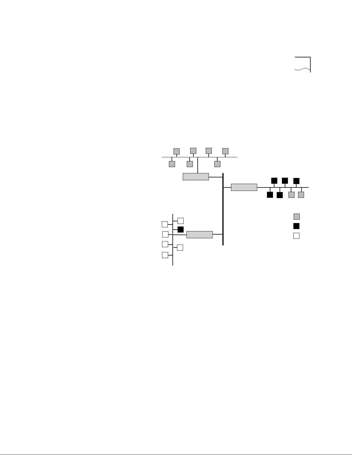
AppleTalk® Network Elements 7-3
AppleTalk® Zones An AppleTalk zone is a logical collection of nodes on an AppleTalk internet.
A zone can include all nodes in a single network or a collection of nodes in
different networks. You assign a unique name to each zone to identify it in
the internet. Figure 7-1 illustrates the relationship between physical
AppleTalk networks and logical AppleTalk zones.
Network 8-8
Network 20-40
Router
Router
Network 47-47
Zone: Administration
Zone: Accounting
Router
Zone: Marketing
Figure 7-1 AppleTalk Networks and AppleTalk Zones
Figure 7-1 shows an AppleTalk internet with three networks: 47-47, 20-40,
and 8-8. Three AppleTalk zones span the networks in this internet:
Administration, Accounting, and Mark eting. Network 20-40 includes two
nodes in the Administration zone and five nodes in the Accounting zone.
Network 47-47 includes a node from the Accounting zone as well as the
Marketing nodes. Network 8-8 consists of nodes in the Administration zone
only.
Creating zones within a network reduces the amount of searching a router
has to do to find a resource on the network. For example, you may want to
gain access to a printer on the network. Instead of searching the whole
network when you want to print a file to a certain printer, the router
searches for it within a particular zone. You gain access to the printer more
Page 80

7-4 CHAPTER 7: ROUTING IN AN APPLETALK® ENVIRONMENT
quickly within the zone because the zone includes fewer devices than the
entire internet does.
Seed Routers A seed router initializes the internet with AppleTalk configuration
information, including network numbers and zone names. The seed router
broadcasts this information so that nonseed routers can learn it. You can
designate a seed router through the Administration Console.
A nonseed router listens for a seed router and then takes the configuration
information from the first seed router it detects. After a nonseed router
obtains the configuration information, it can participate in the network as if
it were a seed router as well.
AppleTalk
Protocols
AppleTalk protocols work together to ensure the seamless flow of
information throughout the AppleTalk internet. Figure 7-2 shows a
simplified view of AppleTalk protocols and their relationship to the OSI
reference model. Together, these protocols provide the following services:
■ Physical Connectivity
■ End-to-End Services
■ Reliable Data Delivery
Page 81
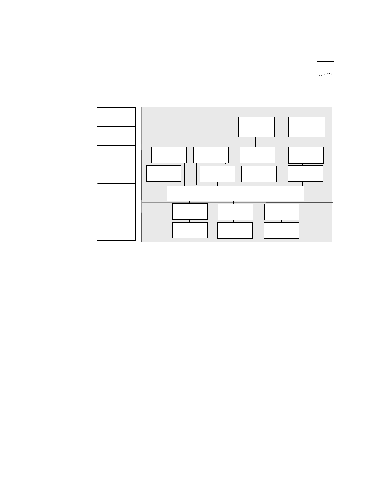
OSI Reference Model
AppleTalk Protocols 7-5
Application
Presentation
Session
Transport
Network
Link
Physical
®
AppleTalk
Data Stream
Protocol (ADSP)
Routing T able
Maintenance
Protocol (RTMP)
Zone Information
TokenTalk
Link Access
Protocol
Token Ring
Hardware
AppleTalk
Filing
Protocol (AFP)
AppleTalk
Protocol (ZIP)
AppleTalk Echo
Protocol (AEP)
Datagram Delivery Protocol (DDP)
®
EtherTalk
Link Access
Protocol
Ethernet
Hardware
Session
Protocol (ASP)
AppleTalk
Transaction
Protocol (ATP)
®
LocalTalk
Link Access
Protocol
®
LocalTalk
Hardware
PostScript
Printer Access
Protocoo (PAP)
Name Binding
Protocol (NBP)
®
®
Figure 7-2 AppleTalk Protocols and the OSI Reference Model
The AppleTalk six-layer protocol suite is not fully compliant with the OSI
seven-layer reference model. However, AppleTalk provides many of the
functions and services provided by OSI. Note that AppleTalk has no specific
protocols for the application layer, since the lower levels provide printer and
file service.
Physical
Connectivity
The physical layer of the OSI protocol stack defines the network hardware.
You can use standard network hardware, such as that defined for Ethernet
and Token Ring networks, with AppleTalk. Apple has also defined its own
network hardware, called LocalTalk, which uses a synchronous RS-422A bus
for communications.
The data link layer provides the interface between the network hardware
and the upper layers of the protocol stack. The AppleTalk data link layer
includes three link access protocols (LAPs): TokenTalk LAP (TLAP), Ethernet
LAP (ELAP), and LocalTalk Link Access Protocol (LLAP).
The AppleTalk Address Resolution Protocol (AARP), which translates
hardware addresses to AppleTalk addresses, also exists at the datalink layer
Page 82

7-6 CHAPTER 7: ROUTING IN AN APPLETALK® ENVIRONMENT
because it is closely related to the Ethernet and token ring LAPs. This
protocol is usually included in the definition of each LAP, so it does not
appear in the reference model. See the section “About AARP” later in this
chapter for more information about this protocol.
The Datagram
Delivery Protocol
(DDP)
The network layer accepts data from the layers above it and divides the data
into packets that can be sent over the network through the layers below it.
The Datagram Delivery Protocol (DDP) transfers data in packets called
datagrams.
Datagram delivery is the basis for building other AppleTalk services, such as
electronic mail. The DDP allows AppleTalk to run as a process-to-process,
best-effort delivery system in which the processes running in the nodes of
interconnected networks can exchange packets with each other.
End-to-End Services The transport layer and the session layer provide end-to-end services in the
AppleTalk network. These services ensure that routers transmit data
accurately between one another. Each layer includes four protocols that
work together to support these services. This section describes these
protocols and provides more detail for those that you can view using the
LANplex Administration Console.
Transport Layer Protocols
An AppleTalk internet has four transport layer protocols:
■ Routing Table M aintenance Protocol (RTMP)
■ AppleTalk Echo Protocol (AEP)
■ AppleTalk Transaction Protocol (ATP)
■ Name Binding Protocol (NBP)
Routing Table Maintenance Protocol (RTMP). The protocol maintains
information about AppleTalk addresses and connections between different
networks. It specifies that each router 1) learns about new routes from the
other routers and 2) deletes routes after a certain period if the local router
no longer broadcasts the route to the network.
Page 83

AppleTalk Protocols 7-7
Each router builds a routing table that is the basis of dynamic routing
operations in an AppleTalk internet. Every 10 seconds, each router sends an
RTMP data packet to the network. Routers use the information that they
receive in the RTMP broadcasts to build their routing tables. Each entr y in
the routing table contains these items:
■ The network range
■ The distance in hops to the destination network
■ The interface number of the destination network
■ The state of each port (good, suspect, bad, really bad)
The router uses these items to determine the best path along which to
forward a data packet to its destination on the network. The routing table
contains an entry for each network that a datagram can reach within 15
hops of the router. The table is aged at set intervals as follows:
1 After a period of time, the RTMP changes the status of an entr y from good
to suspect.
2 After an additional period of time, the RTMP changes the status of an entr y
from suspect to bad.
3 After an additional period of time, the RTMP changes the status of an entr y
from bad to really bad.
4 Finally, the router removes from the table the entry of a nonresponding
router with a really bad status.
The data in the routing table is cross-referenced to the Zone Information
Table (ZIT). This table maps networks into zones. The section on the session
layer protocols includes information about the ZIT.
Figure 7-3 illustrates a simple AppleTalk network and Table 7-1 shows the
corresponding routing table.
Page 84

7-8 CHAPTER 7: ROUTING IN AN APPLETALK® ENVIRONMENT
Network 5-5
Router 802
Router 801
Network 64-64
Router 36
Network 18-20
Interface 2
Router 24
Interface 1
Network 103-103
Interface 3
Router 200
Network 12-12
Figure 7-3 A Simple AppleTalk Network
Table 7-1 The Routing Table for Router 24 in Figure 7-3
Network Range Distance Interface State
5-5 1 2 Good
12-12 3 3 Good
18-20 2 3 Good
103-103 0 1 Good
64-64 1 3 Good
You can view the AppleTalk routing tables in your network through the
Administration Console.
AppleTalk Echo Protocol (AEP). AppleTalk nodes use the AEP to send
datagrams to other nodes in the network. It causes the destination node to
return, or echo, the datagram to the sending node. This protocol can
determine whether a node is accessible before any sessions are started,
and it can enable users to estimate the round-trip delay time between two
nodes.
Page 85

AppleTalk Protocols 7-9
AppleTalk Transaction Protocol (ATP). This protocol, along with the
AppleTalk Data Stream Protocol (ADSP), ensures that DDP packets are
delivered to a destination without any losses or corruption.
Name Binding Protocol (NBP). This protocol translates alphanumeric
entity names to AppleTalk addresses. It maintains a table that references the
addresses of nodes and named entities that reside in that node. Because
each node maintains its own list of named entities, the names directory
within an AppleTalk network is not centralized. It is a distributed database of
all nodes on the internet.
The Session Layer Protocols
An AppleTalk internet has four session-layer protocols:
■ Zone Information Protocol (ZIP)
■ AppleTalk Data Stream Protocol (ADSP)
■ AppleTalk Session Layer Protocol (ASP)
■ Printer Access Protocol (PAP)
The Zone Information Protocol (ZIP). ZIP works with RTMP to maintain a
table that maps network numbers to network zones for the entire AppleTalk
internet. Network zones are the logical groupings of AppleTalk networks. As
we have seen it, the table created by ZIP is called the Zone Information
Table (ZIT). The Administration Console allows you to view the zone
information table by network number or network zone.
ZIP creates a zone information table in each router. Each entry in the ZIT is a
“tuple,” or pair, that includes a network number and a network zone name.
When an NBP packet arrives at the router, it includes the zone name which
the router compares with entries in the zone table. The router then matches
the network number from the matching ZIT tuple to the one in the RTMP
table to find the interface where it can route the packets.
Page 86

7-10 CHAPTER 7: ROUTING IN AN APPLETALK® ENVIRONMENT
AppleTalk Data Stream Protocol (ADSP). The ADSP works with the ATP to
ensure reliable data transmission. Unlike ATP, however, ADSP provides
full-duplex byte-stream delivery. This means that two nodes can
communicate simultaneously. ASDP also includes flow control, so that a
fast sender does not overwhelm a slow receiver.
AppleTalk Session Protocol (ASP). The ASP passes commands between a
workstation and a server once a connection is made between the two. ASP
ensures that the commands are delivered in the same order as they were
sent and returns the results of these commands to the workstation.
Printer Access Protocol (PAP). The PAP maintains communications
between a workstation and a printer or print service. The PAP functions
include setting up and maintaining a connection, transferring the data, and
tearing down the connection on completion of the job. Like other protocols
at the session layer, PAP relies on NBP to find the addresses of named
entities. PAP also depends on ATP for sending data.
Presentation Layer The presentation layer maintains information about files, formats, and
translations between formats. An AppleTalk internet has two protocols at
the presentation layer: the AppleTalk Filing Protocol (AFP) and PostScript®.
AFP provides remote access to files on the network. PostScript is a paged
description language used by many printers.
About AARP The AppleTalk Address Resolution Protocol (AARP) maps the hardware
address of an AppleTalk node to an AppleTalk protocol address. It does this
mapping for both extended and nonextended networks.
When a node on the network initializes, it randomly selects an AppleTalk
address for itself. At the same time, it sends out ten AARP probe packets.
The probe packets determine whether any other nodes on the network are
using the address it has chosen. If a node on the network is already using
that address, the node randomly selects another address and sends out
another probe packet.
Page 87

About AARP 7-11
The AARP maintains an Address Mapping Table (AMT) with the most
recently used hardware addresses and their corresponding AARP addresses.
If an address is not in this table, AARP sends a request to the protocol
address and adds the hardware address to the table when the destination
node replies. You can view this table, called the AARP cache, through the
LANplex Administration Console.
Page 88

7-12 CHAPTER 7: ROUTING IN AN APPLETALK® ENVIRONMENT
Page 89

8
ADMINISTERING VLANS
This chapter describes how to display information about VLANs and how to
configure VLANs.
Through the Administration Console, you can:
■ Display summary or detailed information on VLANs
■ Define or modify a VLAN definition
■ Delete a VLAN definition
Displaying VLAN
Information
Top-Level Menu
system
ethernet
fddi
display
atm
ip
ipx
appletalk
snmp
analyzer
script
logout
mode
ipFragmentation
ipxSnapTranslation
addressThreshold
agingTime
stpState
stpPriority
stpMaxAge
stpHelloTIme
stpForwardDelay
stpGroupAddress
port
packetFilter
➧ vlan
➧ summary
➧ detail
define
modify
remove
➧ bridge
You can display a summary of VLAN information or a detailed report. When
you display a summary, you receive information about the protocols and
ports assigned to each VLAN plus the layer 3 addresses used to manage
flood domains for overlapping IP subnets. The detailed VLAN report includes
the summary information plus additional utilization statistics.
From the top level of the Administration Console, enter:
bridge vlan summary
or
bridge vlan detail
The VLAN information is displayed in the format you specified.
Example of a summary display for several VLANs:
Select menu option (bridge/vlan): summary
Index Protocol Identifier Ports
1 default 0 1-17
2 IP 2 1, 5-7
3 IPX 3 8-10
4 IP 4 7, 12-15
Page 90

8-2 CHAPTER 8: ADMINISTERING VLANS
Index Name Layer 3
1 none
2 eastgroup 158.101.111.16 255.255.255.0
3 westgroup none
4 northgroup 158.101.112.14 255.255.255.0
Example of a detailed display for the VLANs:
Select menu option (bridge/vlan): detail
Index Protocol Identifier Ports
1 default 0 1-17
2 IP 2 1, 5-7
3 IPX 3 8-10
4 IP 4 7, 12-15
Index Name Layer 3
1 none
2 eastgroup 158.101.111.16 255.255.255.0
3 westgroup none
4 northgroup 158.101.112.14 255.255.255.0
index inPackets inBytes outPackets outBytes
1 342 3676 322 2987
2 125 7654 118 6897
3 345 7554 289 7431
4 876 8651 765 7969
Table 8-1 describes these statistics.
Table 8-1 Fields for VLAN Information
Field
Index A system-assigned index used for identifying a particular VLAN
Protocol The protocol suite of the VLAN
Identifier A unique, user-defined (4-byte) integer for use by global
Ports The numbers of the ports assigned to the VLAN
Name A 16-byte character string intended to identify the members of the
Layer 3 Optional parameters consisting of IP subnet and mask used to set
continued
Description
management operations
VLAN
up flood domains for overlapping IP VLAN subnets
Page 91

Defining VLAN Information 8-3
Table 8-1 Fields for VLAN Information (continued)
Defining VLAN
Information
Top-Level Menu
system
ethernet
fddi
atm
➧ bridge
ip
ipx
appletalk
snmp
analyzer
script
logout
display
mode
ipFragmentation
ipxSnapTranslation
addressThreshold
agingTime
stpState
stpPriority
stpMaxAge
stpHelloTIme
stpForwardDelay
stpGroupAddress
port
packetFilter
➧ vlan
summary
detail
➧ define
modify
remove
Field
Description
inPackets Number of flooded broadcast and multicast packets that were
received on the VLAN
inBytes Number of flooded broadcast and multicast bytes that were
received on the VLAN
outPackets Number of flooded broadcast and multicast packets transmitted
over the VLAN
outBytes Number of flooded broadcast and multicast bytes transmitted over
the VLAN
Follow these steps to create a VLAN definition:
1 From the top level of the Administration Console, enter :
bridge vlan define
2 Enter the appropriate protocol suite: (IP, IPX, AppleTalk, XNS,
DECnet, SNA, Banyan, X.25, NetBIOS, NetBEUI, default
3 Enter the VLAN interface identifier.
4 Enter the VLAN name, enclosed in quotation marks.
5 Enter the number(s) of the port(s) or
all to assign all ports to the VLAN.
)
You are prompted to enter the number(s) of the port(s) that can be
assigned to the VLAN.
If you did not choose the IP protocol suite for this VLAN, you have
completed the steps for defining the VLAN.
If you selected the IP protocol suite, follow these steps:
1 Enter
defined to use layer 3 subnet addressing and continue with steps 2
and 3, OR enter
undefined to not use layer 3 addressing.
2 Enter the IP subnet address.
3 Enter the subnet mask.
Page 92

8-4 CHAPTER 8: ADMINISTERING VLANS
Example:
Select menu option (bridge/vlan): define
Enter Protocol Suite
(IP,IPX,AppleTalk,XNS,DECnet,SNA,Banyan,X.25,NetBIOS,NeBEUI,
default):
Enter VLAN Identifier: 1
Enter VLAN Name: “SD Marketing”
Ports 1=FDDI, 2-17=Ethernet
Enter port(s) (1-17|all):
Layer 3 Address (undefined, defined): defined
Enter IP Subnet Address: 158.111.122.0
Enter subnet mask [255.255.0.0] 255.255.255.0
The maximum number of VLANs you can define on a single bridge is 32.
IP
1-5
Modifying VLAN
Information
Top-Level Menu
system
ethernet
fddi
display
atm
ip
ipx
appletalk
snmp
analyzer
script
logout
mode
ipFragmentation
ipxSnapTranslation
addressThreshold
agingTime
stpState
stpPriority
stpMaxAge
stpHelloTIme
stpForwardDelay
stpGroupAddress
port
packetFilter
➧ vlan
summary
detail
define
➧ modify
remove
➧ bridge
To modify VLAN information:
1 From the top level of the Administration Console, enter :
bridge vlan modify
You are prompted to reenter the information that defines the VLAN. Press
the Return or Enter key to accept any value that appears in brackets [ ].
2 Enter the number of the VLAN interface index.
3 Enter the protocol suite for that VLAN:
DECnet, SNA, Banyan, X.25, NetBIOS, NetBEUI, default)
(IP, IPX, AppleTalk, XNS,
4 Enter the VLAN identifier.
5 Enter the VLAN name.
6 Enter the number(s) of the port(s) or all.
7 If you have selected the IP protocol suite and want to use the Layer 3
address information, enter defined for layer 3 addressing. Enter
undefined if you do not want layer 3 addressing.
.
Page 93

Removing VLAN Information 8-5
Example:
Select menu option (bridge/vlan): modify
Select VLAN interface [1-2]: 2
Protocol Suite (IP,IPX,AppleTalk,XNS,DECnet,SNA,
Banyan,X.25,NetBIOS,NetBEUI,default) [AppleTalk]:
VLAN Identifier [1]: 2
VLAN Name [Sales]:
Ports 1=FDDI, 2-17=Ethernet
Enter port(s) (1-17|all) [1-5]:
Layer 3 Address (undefined,defined) [undefined]:
IP
Removing VLAN
Information
Top-Level Menu
system
ethernet
fddi
atm
➧ bridge
ip
ipx
appletalk
snmp
analyzer
script
logout
display
mode
ipFragmentation
ipxSnapTranslation
addressThreshold
agingTime
stpState
stpPriority
stpMaxAge
stpHelloTIme
stpForwardDelay
stpGroupAddress
port
packetFilter
➧ vlan
summary
detail
define
modify
➧ remove
Follow these steps to remove a VLAN definition:
1 From the top level of the Administration Console, enter :
bridge vlan remove
2 Enter the indexes for the VLANs you want to remove.
Example:
Select menu option (bridge/vlan): remove
Select VLAN index(es) (1-2|all): 1
Page 94

8-6 CHAPTER 8: ADMINISTERING VLANS
Page 95

9
ADMINISTERING IP ROUTING
This chapter describes how to set up your LANplex® system to use the
Internet Protocol (IP). For more information about how IP works, see Part III
of this guide.
You can display or configure the following IP characteristics on your
LANplex system:
■ IP interfaces
■ Routes
■ Address Resolution Protocol (ARP) cache
■ UDP Helper
■ ATM ARP Server (for LANplex systems with ATM modules)
■ IP Routing
Administering
interfaces
■ ICMP Router Discovery
■ Routing Information Protocol (RIP)
■ Ping
■ IP statistics
You can define two types of IP interfaces through LANplex Ex tended
Switching software: IP VLAN interfaces and IP LIS interfaces. This section
describes these interfaces and how to administer them.
An IP VLAN interface defines the relationship between an IP Virtual LAN
(VLAN) and the subnets in the IP net work. Every IP VLAN interface has one
IP VLAN associated with it. Each Ethernet or FDDI switching module has one
interface defined for each subnet directly connected to it. You must first
define a VLAN, as described in Chapter 8, Administering VLANs, before you
define an associated IP VLAN interface.
Page 96

9-2 CHAPTER 9: ADMINISTERING IP ROUTING
LIS Interfaces A logical IP subnet (LIS) inter face supports logical IP over ATM. You define
LIS interfaces for the ports on ATM modules only. See the Chapter 11 of the
LANplex® 2500 Operation Guide for more information about the ATM
protocol. See the LANplex® 2500 Administration Console User Guide for
information about how to configure ATM ports.
Interface
Characteristics
Each IP interface has the following information associated with it:
■ IP Address — This address, which is specific to your network, should be
chosen from the range of addresses assigned to your organization by the
central agency. This address defines both the number of the network to
which the interface is attached and the inter face’s host number on that
network.
■ Subnet Mask — A subnet mask is a 32-bit number that uses the same
format and representation as IP addresses. The subnet mask determines
which bits in the IP address are interpreted as the network number, the
subnet number, and the host number. Each IP address bit corresponding to
a 1 in the subnet mask is in the network/subnet part of the address. Each IP
address bit corresponding to a 0 is in the host part of the IP address.
■ Advertisement Address — The switching module uses this IP address
when it advertises routes to other stations on the same subnet. In particular,
the system uses this address for sending RIP updates. By default the
switching module uses a directed advertisement (all 1s in the host field).
■ Cost — This number, between 1 and 15, is used when calculating route
metrics. Unless your network has special requirements, assign a cost of 1 to
all interfaces.
■ Type — The IP interface is one of these types:
■ VLAN, which supports routing between two VLANs
■ LIS, which supports classical IP over ATM
■ State — This status of the IP interface indicates whether the interface is
available for communications.
■ VLAN Interface — When you select VLAN as the interface type, the
Administration Console prompts you for the VLAN index number. The VLAN
index number indicates which bridge ports are associated with the IP
interface. When the LANplex Administration Console menu prompts you for
Page 97

Administering interfaces 9-3
this option, the system displays a list of available VLAN indexes and the
bridge ports associated with them.
■ LIS Interface — When you select LIS as the interface type, the
Administration Console prompts you for LIS interface information. The
information you enter depends on whether you define permanent virtual
circuits (PVCs), switched virtual circuits (SVCs), or both on the LIS interface.
See the LANplex® 2500 Operation Guide for more information on PVCs and
SVCs.
If you define SVCs, you need to enter an ATM ARP server address. This server
maintains the IP-to-ATM address translation table. You can enter the
maximum number of SVCs allowed on this interface. The minimum holding
time determines the least amount of time an SVC connection remains open.
The inactivity timer determines how long the connection can remain open
with no activity after the minimum holding time has expired. You also need
to enter the ATM port number for this interface.
If you define only PVCs on the interface, you need to enter only the PVC
numbers and the ATM port number. The other prompts do not appear
because you do not enter an ATM ARP server address. If you define both
SVCs and PVCs, enter all LIS interface information.
Top-Level Menu
system
➧ interface
ethernet
route
fddi
arp
atm
atmArpServer
bridge
multicast
➧ ip
udpHelper
ipx
routing
appletalk
icmpRouterDiscovery
snmp
rip
analyzer
ping
script
statistics
logout
Displaying
Interfaces
➧ summary
➧ detail
define
modify
remove
addAdvertisement
removeAdvertisement
addPVC
removePVC
You can display both summary and detailed information about all IP
interfaces configured for the system. The detail display contains all the
summary information as well as information about the advertisement
address, PVCs, and VLANs.
To display IP interface information, enter one of the following command
strings from the Administration Console top-level menu:
ip interface summary
OR
ip interface detail
Page 98

9-4 CHAPTER 9: ADMINISTERING IP ROUTING
Example summary display:
IP routing is enabled, RIP is active,
ICMP discovery is disabled.
Index Type IP address Subnet mask Cost State VLAN Index
1 VLAN 158.101.1.1 255.255.255.0 1 Down 2
Index Type IP address Subnet mask Cost State Port
2 LIS 158.101.112.1 255.255.255.0 1 Up 1
Example detail display:
IP forwarding is enabled, RIP is active,
ICMP discovery is disabled.
Index Type IP address Subnet mask Cost State VLAN index
1 VLAN 158.101.1.1 255.255.255.0 1 Down 2
Index Type IP address Subnet mask Cost State Port
2 LIS 158.101.112.1 255.255.255.0 1 Up 1
4 Advertisement Addresses:
158.101.112.200 158.101.112.203 158.101.112.204 158.101.112.205
atmArpServer
47-0000-00-000000-0000-0000-00cc-080001200054-ff
maxSvcCount inactivityTime minHoldingTime
0 1200 60
1PVC:
1/32
Defining an IP LIS
Interface
When you define an IP LIS interface, you specify several general IP interface
characteristics and IP LIS characteristics.
Before you define an IP LIS interface with SVCs, be sure you have defined an
Top-Level Menu
system
➧ interface
ethernet
route
fddi
arp
atm
atmArpServer
bridge
multicast
➧ ip
udpHelper
ipx
routing
appletalk
icmpRouterDiscovery
snmp
rip
analyzer
ping
script
statistics
logout
summary
detail
➧ define
modify
remove
addAdvertisement
removeAdvertisement
addPVC
removePVC
ATM ARP server as described in the section “Administering ATM ARP Ser vers”
later in this chapter. If the LIS interface has only PVCs, you do not need to
define an ATM ARP server.
To define an IP interface:
1 From the top level of the Administration Console, enter :
ip interface define
Page 99

Administering interfaces 9-5
The Console prompts you for the interface’s parameters. To use the value in
brackets, press [Return] at the prompt.
2 Enter the IP address of the interface.
3 Enter the subnet mask of the network to which the interface is to be
connected.
4 Enter the cost value of the interface.
5 Enter the type of IP interface: LIS.
6 Enter the advertisement addresses for this interface. You can enter up to 32
advertisement addresses for each interface. (The maximum number on the
LANplex system is 64.)
7 Enter the LIS information:
■ For a LIS interface with SVCs, enter the ATM ARP server address, the
maximum SVC count, the inactivity timer, the minimum holding time,
and the ATM port associated with the interface. (You can also accept the
defaults for these values.)
■ For a LIS interface with only PVCs, enter the ATM port and the PVCs
associated with the interface. You can enter up to 51 PVCs for each
interface. (The maximum number on the LANplex system is 64.)
LIS interface example with both PVCs and SVCs:
Enter IP address: 158.101.1.1
Enter subnet mask [255.255.0.0]: 255.255.255.0
Enter cost [1]:
Enter interface type (vlan,lis) [lis]:
Enter advertisement address(es) []:
Enter ATM arp server address
[00-0000-00-000000-0000-0000-0000-000000000000-00]:
00000-00cc -000000000001-ff
Accept completed ATM address (yes,no) [yes]:
Enter max. SVC count (0=no max.0) [0]:
Enter inactivity time (0=infinite, 10-10000) seconds [1200]:
Enter min. holding time (0-10000) seconds [60]:
Select ATM port [1]:
Enter PVC(s) (VPI/VCI)[]: 1/32,1/200,1/3330
158.101.112.1
47-0000-00-000000-000
Page 100

9-6 CHAPTER 9: ADMINISTERING IP ROUTING
Defining an IP
VLAN Interface
Top-Level Menu
system
ethernet
➧ interface
fddi
route
atm
arp
bridge
atmArpServer
➧ ip
multicast
ipx
udpHelper
appletalk
routing
snmp
icmpRouterDiscovery
analyzer
rip
script
ping
logout
statistics
summary
detail
➧ define
modify
remove
addAdvertisement
removeAdvertisement
addPVC
removePVC
When you define an IP VLAN interface, you specify several interface
characteristics, as well as the index of the VLAN associated with the
interface.
You must first define a VLAN, as described in Chapter 8, Administering VLANs,
before you define an associated IP VLAN interface.
To define an IP VLAN interface:
1 From the top level of the Administration Console, enter :
ip interface define
The Console prompts you for the interface’s parameters. To use the value in
brackets, press [Return] at the prompt.
2 Enter the IP address of the interface.
3 Enter the subnet mask of the network to which the interface is to be
connected.
4 Enter the cost value of the interface.
5 Enter the type of IP interface: VLAN.
6 Enter the advertisement address for this interface.
7 Enter the index of the VLAN associated with the interface.
Example:
Enter IP address: 158.101.1.1
Enter subnet mask [255.255.0.0]: 255.255.255.0
Enter cost [1]:
Enter interface type (vlan, lis) [vlan]:
Enter advertisement address(es) [158.101.1.255]:
IP VLANs:
Index Ports
3 1-8
4 9-12
Select VLAN index: 3
If you physically change the configuration of your system after defining IP
interfaces, the ports designated for those interfaces might no longer be valid
and you might want to reconfigure your interfaces.
 Loading...