

Page 1

Device View User Guide
®
CoreBuilder 9000 Enterprise
Switch
Transcend Network Control Services Version 5.0.2 for UNIX
http://www.3com.com/
Part No. 09-1504-000e
Published August 1999
Page 2

3Com Corporation
5400 Bayfront Plaza
Santa Clara, California
95052-8145
Copyright © 1999, 3Com Corporation. All rights reserved. No part of this documentation may be reproduced
in any form or by any means or used to make any derivative work (such as translation, transformation, or
adaptation) without written permission from 3Com Corporation.
3Com Corporation reserves the right to revise this documentation and to make changes in content from time
to time without obligation on the part of 3Com Corporation to provide notification of such revision or change.
3Com Corporation provides this documentation without warranty, term, or condition of any kind, either
implied or expressed, including, but not limited to, the implied warranties, terms or conditions of
merchantability, satisfactory quality, and fitness for a particular purpose. 3Com may make improvements or
changes in the product(s) and/or the program(s) described in this documentation at any time.
If there is any software on removable media described in this documentation, it is furnished under a license
agreement included with the product as a separate document, in the hard copy documentation, or on the
removable media in a directory file named LICENSE.TXT or !LICENSE.TXT. If you are unable to locate a copy,
please contact 3Com and a copy will be provided to you.
UNITED STATES GOVERNMENT LEGEND
If you are a United States government agency, then this documentation and the software described herein are
provided to you subject to the following:
All technical data and computer software are commercial in nature and developed solely at private expense.
Software is delivered as “Commercial Computer Software” as defined in DFARS 252.227-7014 (June 1995) or
as a “commercial item” as defined in FAR 2.101(a) and as such is provided with only such rights as are
provided in 3Com’s standard commercial license for the Software. Technical data is provided with limited rights
only as provided in DFAR 252.227-7015 (Nov 1995) or FAR 52.227-14 (June 1987), whichever is applicable.
You agree not to remove or deface any portion of any legend provided on any licensed program or
documentation contained in, or delivered to you in conjunction with, this User Guide.
Unless otherwise indicated, 3Com registered trademarks are registered in the United States and may or may not
be registered in other countries.
3Com, the 3Com logo, Boundary Routing, EtherDisk, EtherLink, EtherLink II, LinkBuilder, Net Age, NETBuilder,
NETBuilder II, OfficeConnect, Parallel Tasking, SmartAgent, SuperStack, TokenDisk, TokenLink, Transcend, and
ViewBuilder are registered trademarks of 3Com Corporation. ATMLink, AutoLink, CoreBuilder, DynamicAccess,
FDDILink, NetProbe, and PACE are trademarks of 3Com Corporation. 3ComFacts is a service mark of
3Com Corporation.
IBM and NetView are registered trademarks of International Business Machines Corporation. Microsoft,
MS-DOS, Windows, and Windows NT are registered trademarks of Microsoft Corporation. Novell and NetWare
are registered trademarks of Novell, Inc. UNIX is a registered trademark of X/Open Company, Ltd. in the
United States and other countries.
All other company and product names may be trademarks of the respective companies with which they are
associated.
Page 3

ONTENTS
C
A
BOUT THIS GUIDE
Conventions 7
Related Documentation 8
Help Systems 8
Year 2000 Compliance 8
Technical Support 8
A
1
2
BOUT DEVICE VIEW
About Device View 10
New in This Release 11
Management Support Matrix 12
U
SING DEVICE VIEW
Preparing Devices for Management 16
Preparing the Management Platform 17
Starting Device View 17
Community Strings 17
Using the Command Line 17
Using Transcend Central 18
Viewing Network Devices 18
Managing Media, Modules, Segments, and Ports 20
Using Media Selection Lists 21
Viewing and Changing Settings 22
Using Online Help 24
M
3
ANAGING DEVICES
Managing CoreBuilder 9000 Switches 26
Chassis Management 26
Module Management 28
Ethernet Port Setup 30
Page 4

Managing Power Systems 31
Managing the CoreBuilder 9000 Switch Power Supply 32
A
4
DVANCED MANAGEMENT TASKS
Viewing Performance Statistics 38
Managing Virtual LANs 39
VLANs on the CoreBuilder 9000 41
Features 43
IEEE 802.1Q and Per-port Tagging 45
VLAN IDs 46
Terminology 46
Procedural Guidelines 47
Selecting VLANs 49
Creating, Editing, or Deleting VLANs 50
I
NDEX
Page 5

BOUT THIS
A
About This Guide provides an overview, describes conventions, tells you
where to look for specific information, and lists other publications that
may be useful.
This version of the Device View User Guide describes how to manage the
3Com CoreBuilder 9000 Enterprise Switch using Device View software.
This release of Device View also includes support for the CoreBuilder
9400 Gigabit Ethernet Switch.
3Com provides this guide in electronic (PDF) format only. The information
in this guide supplements the Device View User Guide supplied with
Transcend Network Control Services (TNCS) Version 5.0. For information
on Device View support of other 3Com hubs and switches, see the Device
View User Guide included with TNCS v5.0.
G
UIDE
If the information in the Release Notes shipped with your product differs
from the information in this guide, follow the Release Notes.
For additional information about using Device View to work with 3Com
devices on your network, refer to:
■ Publications provided with TNCS v5.0 software:
■
Network Administration Guide is a guide to setting up network
resources and administering your network effectively by
configuring network components, managing assets, tracking
changes, and managing the security of the network
■
Network Troubleshooting Guide is a guide to status monitoring,
performance management, and capacity planning
Online Help which provides more detailed information about how
■
Device View works. Online Help is automatically installed onto your
system when you install Device View.
Page 6

6 A
BOUT THIS GUIDE
For detailed information on the CoreBuilder 9000 Enterprise Switch and
its modules, see the documentation supplied with your hardware,
especially the
CoreBuilder 9000 Implementation Guide
.
This guide is intended for network administrators who understand
networking technologies and how to integrate networking devices. You
should have a working knowledge of:
Local Area Networking and Internetworking, including:
■
■
Transmission Control Protocol/Internet Protocol (TCP/IP)
■
Simple Network Management Protocol (SNMP)
Network management systems
■
3Com devices on your network
■
You should also be familiar with the interface and features of the
Transcend management software you have installed.
Finding Specific
Information in
This Guide
This table shows the location of specific information in this guide.
If you are looking to... Turn to...
Learn about Device View, supported devices, and view a
management support matrix
Get started with Device View and find out about the Device View
user interface and how to use it to set up 3Com devices on your
network
Find out how Device View helps you to manage hubs, switches,
bridge/routers, and remote access routers
Find out how you can view performance statistics and manage
Virtual LANs (VLANs)
Chapter 1
Chapter 2
Chapter 3
Chapter 4
Page 7

Conventions 7
Conventions
Table 1 and Table 2 list conventions that are used throughout this guide.
Table 1 Notice Icons
Icon Notice Type Description
Information note Information that describes important features or
instructions
Caution Information that alerts you to potential loss of data or
Warning Information that alerts you to potential personal injury
Table 2 Text Conventions
Convention Description
Screen displays
Syntax
Commands
The words “enter”
and “type”
Keyboard key names If you must press two or more keys simultaneously, the key
(continued)
potential damage to an application, system, or device
This typeface represents information as it appears on the
screen.
The word “syntax” means that you must evaluate the syntax
provided and then supply the appropriate values for the
placeholders that appear in angle brackets. Example:
To enable RIPIP, use the following syntax:
SETDefault !<port> -RIPIP CONTrol =
Listen
In this example, you must supply a port number for <port>.
The word “command” means that you must enter the
command exactly as shown and then press Return or Enter.
Commands appear in bold. Example:
To remove the IP address, enter the following command:
SETDefault !0 -IP NETaddr = 0.0.0.0
When you see the word “enter” in this guide, you must type
something, and then press Return or Enter. Do not press
Return or Enter when an instruction simply says “type.”
names are linked with a plus sign (+). Example:
Press Ctrl+Alt+Del
Page 8

8 A
BOUT THIS GUIDE
Table 2 Text Conventions (continued)
Convention Description
Words in italics Italics are used to:
■
Emphasize a point.
■
Denote a new term at the place where it is defined in the
text.
■
Identify menu names, menu commands, and software
button names. Examples:
From the Help menu, select Contents.
Click OK.
Related Documentation
Help Systems
Year 2000 Compliance
Technical Support
This guide is complemented by other 3Com documents and
comprehensive help systems.
Most user guides and release notes are available in Adobe Acrobat
Reader Portable Document Format (PDF) or HTML on the 3Com
World Wide Web site:
http://www.3com.com/
Each Transcend application contains a help system that describes how to
use all the features of the application. Help includes window descriptions,
instructions, conceptual information, and troubleshooting tips for that
application.
For information on Year 2000 compliance and 3Com products, visit the
3Com Year 2000 Web page:
http://www.3com.com/products/yr2000.html
3Com Corporation provides technical assistance through a variety of
services, including the World Wide Web, a Bulletin Board Service,
automated fax, and technical telephone support. For more information,
access the following Web page:
http://www.3com.com/util/enterprise.html#support
Page 9

1
BOUT
A
Transcend® Device View enables you to monitor and set up the 3Com
hubs, switches, bridge/routers, and remote access devices in your
enterprise-wide network.
This version of the Device View User Guide supplements the information
provided in the Device View User Guide included in Transcend Network
Control Services, v5.0. See “About This Guide” for the scope of this
document and other sources of information.
This chapter introduces Device View and summarizes management
support for 3Com devices.
■ About Device View
■ New in This Release
■ Management Support Matrix
D
EVICE
V
IEW
Page 10

10 C
HAPTER
BOUT DEVICE VIEW
1: A
About Device View
Device View provides an easy-to-use SNMP-based interface for managing
the connectivity devices in your network. Transcend Network Control
Services customizes the network management platform to add
meaningful symbols to the network map, and associate the symbols that
represent manageable devices with applications that support them.
When you manage a device, Device View creates an accurate graphical
representation of the hardware that enables you to view the status of
ports and indicators. You can use the picture to set up device and port
parameters, and collect detailed statistics.
The CoreBuilder 9000 16-slot chassis, 8-slot chassis, and 7-slot chassis
support frame-based technology with the Gigabit Ethernet Switch Fabric
Module, Fast Ethernet switching modules, and Gigabit Ethernet interface
modules.
The CoreBuilder 9000 16-slot chassis also supports cell-based technology
with the Asynchronous Transfer Mode (ATM) Switch Fabric Module and
ATM Interface Modules. However, Device View only supports the
frame-based system.
Page 11

New in This Release 11
New in This Release
Transcend NCS v5.0.2 for UNIX includes Device View functionality that
enables you to manage the CoreBuilder 9000 Enterprise Switch and the
CoreBuilder 9400 Gigabit Ethernet Switch. Management support is
shown in Table 3
Table 3 Device View Support for the CoreBuilder 9000 Enterprise Switch
Description
16-slot chassis 3CB9E16
8-slot chassis 3CB9E8
7-slot chassis 3CB9E7
EME (EME1)
Enterprise Management Engine
EMC
Enterprise Management Controller
24-port Gigabit Ethernet
Switch Fabric Module
24-port Gigabit Ethernet
Switch Fabric Module with additional
trunk
2-port 1000BASE SX
Interface Module
2-port 1000BASE LX
Interface Module
9-port 1000BASE-SX Gigabit Ethernet
Layer 2 Switching Module
10-port 100BASE FX
Layer 2 Switching Module
20-port 100BASE TX
Layer 2 Switching Module
36-port 10/100BASE TX
Layer 2 Switching Module
36-port 10/100BASE TX
Telco Layer 2 Switching Module
10-port 100BASE FX
Layer 3 Switching Module
12-port 100BASE TX
Layer 3 Switching Module
Agent
Version
2.1 3CB9EME
2.0 3CB9EMC
2.1 3CBFG24
2.1 3CBFG24T
2.1 3CB9LG9MC
2.1 3CB9LF10MC
2.1 3CB9LF20R
2.1 3CB9LF36R
2.1 3CB9LF36T
2.2 3CB9RF10MC
2.2 3CB9RF12R
3Com
Part Number
3CB9LG2MC
3CB9LG2SC
Page 12

12 C
HAPTER
BOUT DEVICE VIEW
1: A
Management Support Matrix
This section describes the management features that are available for
Small Office and Enterprise Switches, including the CoreBuilder 9000
Enterprise Switch and the CoreBuilder 9400 Gigabit Ethernet Switch.
To find information about other 3Com devices, see the
included with TNCS, v5.0.
Guide
Device View User
Table 4 shows the small office and enterprise switches that you can
manage with Device View.
Table 4 Small Office and Enterprise Switches
Monitor status
Set up device
Use SuperStack groups
Upgrade agent software
Manage ports
Manage console port
Manage bridging
Create resilient links
Create VLANs
View statistics
Set up traps
Manage security
CoreBuilder 9000
CoreBuilder 9400
CoreBuilder 2500
CoreBuilder 3500
CoreBuilder 5000 FastModule
CoreBuilder 6000
LANplex 2016
LinkSwitch 500
LinkSwitch 1000
LinkSwitch 1200
LinkSwitch 3000
OfficeConnect Switch 140M
SuperStack II Desktop Switch
SuperStack II Switch 610
SuperStack II Switch 630
SuperStack II Switch 1000
SuperStack II Switch 1100
SuperStack II Switch 2200
*
Page 13

Management Support Matrix 13
Table 4 Small Office and Enterprise Switches (continued)
Monitor status
Set up device
Use SuperStack groups
Upgrade agent software
Manage ports
Manage console port
Manage bridging
Create resilient links
Create VLANs
View statistics
Set up traps
Manage security
(continued)
SuperStack II Switch 3000
SuperStack II Switch 3300
SuperStack II Switch IP 3800
SuperStack II Switch 3900
SuperStack II Switch 9000 SX
SuperStack II Switch 9300
* Includes CoreBuilder 5000 Token Ring FastModules. CoreBuilder 5000 SwitchModules are
managed through the CoreBuilder 5000 SwitchModule Manager application. See Using
Online Help in Chapter 2 for more information on CoreBuilder 5000 SwitchModule
Manager or see the online Help.
In addition to the management functions shown in Table 4, you can also
use Device View to perform the following tasks:
■ Manage power supplies (CoreBuilder 9000 Switch)
■ Enable 802.1Q tagging (CoreBuilder 9000 Switch)
Set up roving analysis port (CoreBuilder 9000 Switch and CoreBuilder
■
9400 Switch)
Monitor port trunking (CoreBuilder 9000 Switch and CoreBuilder
■
9400 Switch)
Monitor backplane ports (CoreBuilder 9000 Switch)
■
Page 14

14 C
HAPTER
BOUT DEVICE VIEW
1: A
Page 15

2
SING
U
This chapter describes the Device View interface and explains how to run
the application and use it to set up manageable devices.
This version of the Device View User Guide supplements the information
provided in the Device View User Guide included in Transcend Network
Control Services, v5.0. See “About This Guide” for the scope of this
document and other sources of information.
This chapter contains:
■ Preparing Devices for Management
■ Starting Device View
■ Viewing Network Devices
■ Managing Media, Modules, Segments, and Ports
D
EVICE
V
IEW
■ Viewing and Changing Settings
■ Using Online Help
Page 16

16 C
HAPTER
SING DEVICE VIEW
2: U
Preparing Devices for Management
The ability to set up devices from the SNMP management station is an
important part of your configuration management strategy. To prepare to
manage devices on your network, you need to perform the following key
tasks:
Discover devices and create network maps — The management system
1
organizes your network into a hierarchical series of maps and submaps.
This structured, hierarchical approach provides a high-level submap that
represents your entire network, and detailed views of portions of the
network, which helps you analyze and troubleshoot your network. Each
map contains objects and symbols that represent parts of your network.
Map symbols represent network resources as graphical icons, and relate
to a set of basic management information that is stored in the
management system’s object database.
Set up SNMP parameters — The management station uses SNMP to
2
and
management information on the agent. To make sure you can
set
manage devices on your network, you need to set the SNMP parameters
that affect how the system communicates with devices.
Whenever a management application requests information from an
SNMP agent, it provides a
community name
. The community name is a
text string that acts as a password, and is used to authenticate every
packet that is sent from the management application and the agent.
The management station must use the same community name that is
configured on the agent. Setting the community name determines your
level of management control over the device.
get
Some advanced management platforms enable you to set global values
for other SNMP parameters, such as time-out and retry values, polling
intervals, and SNMP proxy agents, that affect the way you manage
devices.
For the CoreBuilder 9000 Enterprise Switch, you must configure the EME
with certain parameters before you access the Administration Console of
any switch fabric module or interface module, and before you access the
system through an external Simple Network Management Protocol
(SNMP) application. See the
Engine User Guide
Start polling device status — Map symbols can show the status of the
3
for more information.
CoreBuilder 9000 Enterprise Management
managed object, so you can use your network map to quickly find out
the state of the resources that make up your network.
Page 17

Preparing the Management Platform 17
Define groups and manage devices — To help you organize managed
4
devices, Device View enables you to create SuperStack groups. You can
then select one symbol that represents the devices, and manage all the
devices in a single window.
Set up IP address of management station — Each device needs to be set
5
up with the IP address of the management station in order to send traps
to it.
Preparing the Management Platform
Starting
Device View
Community Strings
To allow the management platform to communicate properly with the
managed devices, you need to set up the read-write community string on
the management station. For detailed instructions on performing this
task, refer to the network management documentation.
You can launch Device View from a command line or from Transcend
Central.
Integration of Device View with your management platform is performed
automatically when you install Transcend Network Control Services.
Community strings are stored in two locations: your network
management platform and the Transcend database. Device View uses the
community strings stored in the Transcend database. It is important that
the community string information be identical in both locations for a
particular device to maintain communication between Transcend
applications and the device.
You can use Transcend Central to import device information (including
community strings) from the network managment platform to the
Transcend database. However, community string changes made in
Transcend Central are not propogated to the network managment
platform. Therefore, if you want to change the community string for a
device, reset the string in the network managment platform and then
change the string in the Transcend database by using Transcend Central
to re-import the device.
Using the Command
Line
At the prompt, enter the command:
/usr/3Com/dv/bin/dv
where
hostname
is the hostname or IP address of the device.
hostname
Page 18

18 C
HAPTER
SING DEVICE VIEW
2: U
If you add the name of the directory containing the Device View
application to your path, you can launch the Device View simply by
entering:
dv
hostname
If the device recognizes the community string and can be reached on the
network, Device View displays the device. Otherwise, enter:
dv -c
community_string
-device
hostname
Ensure the device’s community string is correctly set up for the
management platform.
Device View displays a graphical representation of the device. You can
start multiple sessions of Device View to see details of several devices on
screen at the same time.
Using Transcend
Central
Viewing Network Devices
Device View can be started from Transcend Central.
To start Device View:
Select a device or a SuperStack group and click the right mouse button.
1
For a CoreBuilder 9000 Switch, expand the CoreBuilder 9000 Enclosure
group, then select the CoreBuilder 9000 device and click the right mouse
button.
From the shortcut menu, select
2
, then choose
Tool s
Device View
.
When you choose to manage a device, Device View presents a bitmap
picture of the front panel of the managed device that reflects the
hardware configuration and the condition of status indicators, ports, and
modules.
Figure 1 shows the Device View representation (device mimic) of a 16-slot
CoreBuilder 9000 Switch. The title bar of the Device View window
displays the name or IP address of the device you are managing. At the
bottom of the window, the status bar provides messages and shows the
direction of communication between the management station and the
device. To update the display, click
Refresh
on the View menu.
Page 19
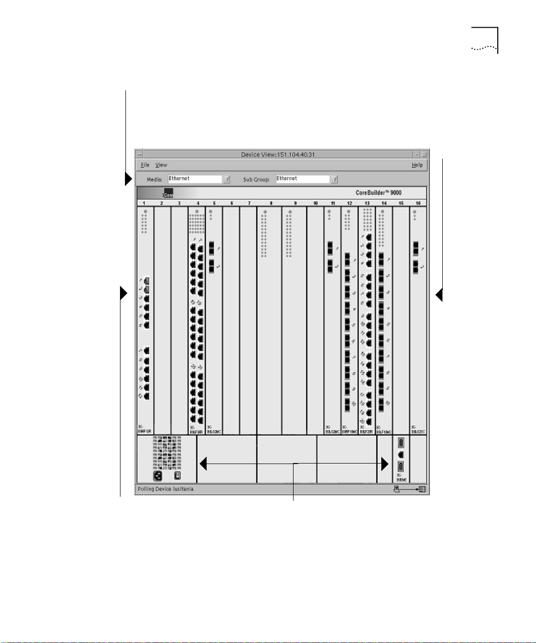
Viewing Network Devices 19
Media and Sub Group —
Enables you to highlight
associated ports.
Modules — Select a module
with the left mouse button,
and click the right mouse
button to access a shortcut
menu.
Ports — Select one or more
ports with the left mouse
button, and click the right
mouse button to access a
shortcut menu.
Figure 1
Managing a CoreBuilder 9000 Switch
Power Supply/Fan (left) —
Color indicates status.
EME (right) — Enterprise
Management Engine
Page 20

20 C
HAPTER
SING DEVICE VIEW
2: U
Managing Media, Modules, Segments, and Ports
Device View enables you to set up all aspects of the devices you manage.
You can select and work with:
Devices
■
Console ports
■
Modules
■
Trans cei ver s
■
Segments
■
Ports
■
Virtual LANs
■
Trunk s
■
In many cases, you can choose multiple objects and set them up at the
same time.
You select an object in Device View by clicking on it, then select other
objects by either dragging over them, or clicking the first object and then
holding down Ctrl and choosing the other objects you want to select.
When you select objects, Device View highlights them. You can deselect
objects by clicking on them again.
When you highlight a port, Device View highlights LEDs and other status
indicators associated with the port, to make it easier to check port status.
When you choose to set up multiple devices or ports, Device View checks
the management features that the devices support. If some of your
changes cannot be made, because one or more devices do not support
them, Device View provides you with a detailed summary of the changes
that were applied, and those that were not applicable.
Page 21

Managing Media, Modules, Segments, and Ports 21
Using Media
Selection Lists
Device View also provides two media selection lists called Media and Sub
Group which help you to choose the features you want to manage. For
example, this makes it easy to work with all Fast Ethernet ports, find out
which ports belong to VLAN 2, or choose all the ports that are connected
to a cascaded segment in a stack of PS Hub devices as in Figure 2.
Media
— Enables you to
choose port types, virtual
LANs, or the entire stack
Sub Group
duplex mode, cascaded segment in
a stack of segmentable hubs, or
— Selects half or full
VLAN name
Figure 2 Filtering with the Media Selection Bar
To use the media selection lists:
Choose your selection in the Media list box.
1
Typical media selections are:
■
Ethernet, Fast Ethernet, or Gigabit Ethernet, which highlight port
interfaces according to port speed
■
Console, which highlights all console ports
■
Vlan, which enables you to highlight ports that belong to the
virtual LAN you choose in the Sub Group list
■
SuperStack, which highlights all the devices in a stack
When you make your selection, the options in the Sub Group list box
change to reflect the media you want to work with. For example, the sub
group may be Half Duplex or Full Duplex, the number of a cascaded
segment, or the number of a VLAN.
Choose your selection in the Sub Group list box.
2
Devices or ports matching your selection are highlighted.
Manage the selection by clicking the right mouse button and choosing a
3
command from a shortcut menu.
Page 22

22 C
HAPTER
SING DEVICE VIEW
2: U
Viewing and
Changing Settings
You can access management information about devices, segments, ports,
and virtual LANs by highlighting the feature you want to work with and
clicking the right mouse button to access a shortcut menu. For modular
chassis such as the CoreBuilder 9000 Switch, you can also highlight the
entire chassis or a module. The shortcut menu you see depends on the
element you have selected.
The shortcut menu does not appear for CoreBuilder 5000 and ONline
devices. Instead, you click and hold the right mouse button on the
module or port you want to manage, move the mouse pointer over a
popup module description, and release the mouse button.
To enable or disable a port interface, highlight the port and select
or
Disable
from the shortcut menu.
Enable
— Select one or more
Ports
ports that you want to work
with, either by clicking them
or using the
filters.
Group
Figure 3 Selecting an Ethernet Port
Media
and
Sub
Shortcut menu
the menu and choose to
Configure
, or view performance graphs.
— Right-click to access
Enable, Disable
The shortcut menu displays a series of commands that relate to the
feature you select. Clicking
Configure
enables you to set up the feature
using a notebook-style interface that divides management information
into a series of sections within the same window. Within each section,
tabbed pages group the settings you can configure. When you select a
,
Page 23

Managing Media, Modules, Segments, and Ports 23
different section, the tab labels at the top of the page change
automatically to show which options are available within that section.
The interface for CoreBuilder 5000 and ONline devices uses a single
tabbed page for most module and port configuration forms.
Device View provides dialog boxes that enable you to read and write
management information. When you want to update information in a
dialog box, click Refresh to cause Device View to read new information
from the device.
Available tabs for the Device section
Available sections
Figure 4 Using Tabs in the Notebook Interface
Tab order and position can vary for different devices. Also, some tabs are
specific to particular devices.
When you change management settings in Device View, always make
sure you click Apply to write the changes to the device you are managing.
Alternatively, to discard your changes and close the dialog box, click on
the Exit command on the File menu.
Page 24

24 C
HAPTER
SING DEVICE VIEW
2: U
Using Online Help
This guide introduces you to using Device View to manage 3Com
enterprise network equipment in your network. For detailed information
about the settings that you can read and set, what fields and controls
mean, and how you should use them, refer to the comprehensive online
help that is automatically placed on your system when you install
Device View.
Figure 5 Device View Help for Security Settings
You can access help for the application you are using in different ways.
Device View Help is context-sensitive, which means that the help system
produces information that relates to the management settings you are
using when you click the
To access Device View help, either click on a
Help
button.
button in a window or
Help
dialog box to access help on the tasks you can perform, or use the Help
menu to use the Contents page or index to locate the information you
want to find.
Page 25

3
ANAGING
M
Device View provides management settings that are appropriate to the
feature set of the managed resource. For example, you may need to set
up cascaded segments on segmentable hubs, virtual LANs (VLANs) on
switches, or ISDN bridging on remote access devices. Device View
customizes the interface to match the needs of the systems you are
managing.
This chapter describes management settings that Device View provides
for hubs and switches, high-function switches, remote access devices and
routers, and power systems.
This version of the Device View User Guide supplements the information
provided in the Device View User Guide included in Transcend Network
Control Services, v5.0. See “About This Guide” for the scope of this
document and other sources of information.
EVICES
D
This chapter contains:
■ Managing CoreBuilder 9000 Switches
■ Managing Power Systems
Page 26

26 C
HAPTER
ANAGING DEVICES
3: M
Managing CoreBuilder 9000 Switches
Chassis Management
This section describes the management features that Device View
provides for CoreBuilder 9000 Switches in your network.
This section contains:
Chassis Management
■
Module Management
■
Ethernet Port Setup
■
To manage a CoreBuilder 9000 Switch:
View the front of the chassis by starting Device View.
1
Highlight the entire chassis and click the right mouse button. Device View
2
displays a shortcut menu with the following options:
Config
a
, and
If you select
includes the
Setup
Inventory
tabbed pages. Refer to Device Settings for information on these
.
Configure
, Device View displays the
Information, Backplane Connections, Reset
Configure, IP
section, which
Device
, and
Tru nk
pages.
If you select
b
IP Config
section, which includes the
, Device View displays the
ARP Cache, Interfaces
IP Configuration
, and
Routes
tabbed
pages. Refer to IP Configuration Settings for information on these
pages (valid for Layer 3 modules only).
If you select
c
includes the
Inventory
PSU, Fan Status, Modules, Temperature
, Device View displays the
Chassis
, and
section, which
tabbed pages. Refer to Chassis Settings information on these pages.
3
Click
after making changes to any settings.
Apply
Device Settings
The
Information — Provides detailed information about a device (for
■
section contains the following tabbed pages:
Device
example, the IP address, MAC address, and IPX addresses) and enables
you to enter a name, location, and contact.
Reset— Allows you to reboot your device. Rebooting the device
■
disconnects any rlogin and telnet sessions. It also temporarily disrupts
your ability to poll the device using Transcend applications, and the
device shows up as unreachable.
Fabric
Page 27

Managing CoreBuilder 9000 Switches 27
■ Backplane Connections — Displays a table showing the current
backplane connections (switch fabric module to interface module) and
the status of each connection.
Trunk Setup — Displays a table showing the trunks, and member
■
ports, currently defined on the device.
IP Configuration Settings
The IP Configuration section contains read-only pages, which are valid for
Layer 3 modules only. To create, edit, or delete IP configuration setting,
select the appropriate Layer 3 module in your CoreBuilder 9000 Switch.
The IP Configurationsection includes the following tabbed pages:
■ ARP Cache — Allows you to view the Address Resolution Protocol
(ARP) cache. The ARP cache is a table of IP addresses learned by the
device and their corresponding MAC addresses.
■ Interfaces — Allows you to view the IP interfaces defined on the
CoreBuilder 9000 Switch. You define interfaces to establish the
relationship between the ports on your device and the subnetworks in
your IP network. IP interfaces are used for managing the device and to
help route packets on your network. You can have up to 32 IP
interfaces for management for each device.
■ Routes — Allows you to view the IP routes defined on the CoreBuilder
9000 Switch. Each device maintains a table of routes to other IP
network, subnetworks, and hosts. You can either make static entries
in this table or configure the device using the Routing Information
Protocol (RIP).
When configuring the default route, neither a destination address or
network mask are required. If the default type is selected the first two
fields will be disabled. Only one default route can exist, so if one is
already defined, it should not be possible to select the default type.
Chassis Settings
The Chassis section contains the following tabbed pages:
PSU — Provides detailed information about the power supplies
■
installed in the chassis.
Fan Status — Allows you to manage and view information about the
■
fan units installed in the chassis.
Modules — Provides detailed information about the modules installed
■
in the chassis.
Page 28

28 C
HAPTER
ANAGING DEVICES
3: M
Temperature — Allows you to view temperature information for a
■
chassis.
Fabric — Allows you to view information for the Gigabit Ethernet
■
(GEN) Switch Fabric Module (or modules) operating in the chassis.
Module Management
To manage CoreBuilder 9000 Switch modules:
View the front of the chassis by starting Device View.
1
Highlight the module and click the right mouse button. Device View
2
displays a shortcut menu. The menu options include the following:
Configure Module
Config
a
(Layer 3 modules only).
If you select
Module
Connections
Configure Module
section, which includes the
(switch fabric module only) tabbed pages. Refer to
and
Configure Bridge
, Device View displays the
(all modules), and
, VLANs, and
Reset
RAP
Config
Backplane
Module Settings for information on these pages.
If you select
b
which includes the
Configure Bridge
General
, Device View displays the
and
Spanning Tree
tabbed pages. Refer to
Bridge
Bridge Settings for information on these pages.
If you select
c
section, which includes the
, Device View displays the
RAP
Analyzer Setup
(Roving Analysis Port)
RAP
and
Monitor Setup
pages. Refer to RAP Settings information on these pages.
If you select
d
IP Config
section, which includes the
, Device View displays the
ARP Cache, Interfaces
IP Configuration
, and
Routes
pages. Refer to IP Configuration Settings for information on these
pages.
3
Click
after making changes to any settings.
Apply
and
IP
section,
tabbed
tabbed
Module Settings
The
Config Module
Reset— Allows you to reboot a module. Rebooting a module
■
section contains the following tabbed pages:
disconnects any rlogin and telnet. It also temporarily disrupts your
ability to poll the module using Transcend applications, and the
module shows up as unreachable.
VLANs — Show the VLANs currently defined on the module and
■
enables you to create new VLANs, or modify or delete existing VLANs.
Page 29

Managing CoreBuilder 9000 Switches 29
■ Backplane Connections — For switch fabric modules, displays a table
showing the current backplane connections (switch fabric module to
interface module) and the status of each connection.
Bridge Settings
The Bridge section contains the following settings:
■ General — Allows you to configure standard bridge parameters.
■ Spanning Tree — Allows you to view and configure spanning tree
parameters such as the bridge priority, hello time, maximum age, and
forward delay.
RAP Settings
The RAP (Roving Analysis Port) section contains the following settings:
■ Monitor Setup — Allows you to set up the port whose traffic you
want to analyze. The monitor port mirrors incoming and outgoing
traffic to the analyzer port for analysis.
■ Analyzer Setup — Allows you to set up the destination port that will
receive and process monitored traffic. The analyzer is the location
where RMON processing occurs.
Roving analysis enables you to monitor port traffic for network
management purposes. Device View allows you to choose any network
segment that is attached to a supported device and monitor its activity
using a network analyzer (also called a "probe").
You can monitor a port to:
■ Analyze traffic loads on each segment so that you can continually
optimize your network loads by moving network segments
■ Troubleshoot network problems (for example, to find out why a
particular segment has so much traffic.)
When you set up roving analysis, the system copies port data and
forwards it to the port on which the network analyzer is attached without disrupting the regular processing of the packets.
IP Configuration Settings
The IP Configuration section contains the following settings:
Page 30

30 C
HAPTER
ANAGING DEVICES
3: M
ARP Cache — Allows you to remove or flush the Address Resolution
■
Protocol (ARP) cache. The ARP cache is a table of IP addresses learned
by the device and their corresponding MAC addresses.
Interfaces — Allows you to create, edit, and delete IP interfaces. You
■
define interfaces to establish the relationship between the ports on
your device and the subnetworks in your IP network. IP interfaces are
used for managing the device and to help route packets on your
network. You can have up to 32 IP interfaces for management for
each device.
Routes — Allows you to create a new static or default route or edit
■
existing ones. Each device maintains a table of routes to other IP
network, subnetworks, and hosts. You can either make static entries
in this table or configure the device using the Routing Information
Protocol (RIP).
When configuring the default route, neither a destination address or
network mask are required. If the default type is selected the first two
fields will be disabled. Only one default route can exist, so if one is
already defined, it should not be possible to select the default type.
Ethernet Port Setup
The Device View window shows a bitmap representation (device mimic)
of the front of the device. The mimic displays installed modules (for
modular switches) and all front panel ports. Connectors such as an AUI
port or transceiver module that physically may be on the rear of the
device are shown in this view. However, CoreBuilder 9000 Switch
backplane ports are not displayed.
To set up switch ports:
View the front panel by starting Device View.
1
Highlight one or more ports, click the right mouse button, and select
2
Configure
Device View provides you with the
Spanning Tree
on the shortcut menu.
, and
tabs. Refer to the following sections to find out
VLAN
section which contains
Ports
Ethernet
more about these groups of settings.
,
Page 31

Managing Power Systems 31
Managing Power Systems
Figure 6
3 Click
The
■
Managing Ethernet Ports on High-Function Switches
Apply
after making changes to any settings.
Ports
section contains the following settings:
Ethernet — Enables you to enable, disable, and configure Ethernet
ports on a device.
■
Spanning Tree — Allows you to view and configure spanning tree
parameters such as the path cost and port priority.
■
VLAN — Allows you to view and configure the identifiers and names
of the VLANs to which a port belongs.
This section describes special power management features for the
CoreBuilder 9000 Switch. For a complete description of power
management in the CoreBuilder 9000 Switch, see the
Enterprise Management Engine User Guide
.
CoreBuilder 9000
Page 32

32 C
HAPTER
ANAGING DEVICES
3: M
Managing the
CoreBuilder 9000
Switch Power Supply
Device View provides you with the following power management
features for the CoreBuilder 9000 Switch:
You can find out the status of power supplies and fan units, and
■
temperature data for the chassis.
You can set Admin Status to Fault Tolerant or Non-Fault Tolerant
■
mode.
You can enable or disable Overheat Power Down mode.
■
You can set the Power Class.
■
You can enable or disable the Power State
■
To manage a CoreBuilder 9000 Switch power supply:
Select the CoreBuilder 9000 Switch chassis.
1
Click the right mouse button.
2
From the shortcut menu, select
3
Select the
4
PSU, Fan Status
Inventory
, or
Temperature
.
tab.
The Fan Status and Temperature dialog boxes are informational. The PSU
dialog box provides status information, enables you to set Admin Status
and Overheat Power Down mode, and provides access to the Modify PSU
dialog box. The Modify PSU dialog box enables you to change the Power
Class setting and the Power State mode.
Admin Status
You can set Admin Status to Fault Tolerant or Non-Fault Tolerant mode.
Power non-fault-tolerant
A mode in which 100 percent of the power that can be allocated to
■
is:
modules is available to them (no power is held in reserve).
The default mode for power supplies as shipped.
■
While the chassis is running in power non-fault-tolerant mode, the
amount of power that is available to modules is determined only by the
number of power supplies that are installed. If a power supply fails while
the chassis is running in non-fault-tolerant mode:
Installed modules continue to operate without interruption if the
■
output of the remaining power supplies is sufficient to provide
adequate power to all installed modules.
Page 33

Managing Power Systems 33
■ The EME may shut down selected interface modules in an attempt to
bring installed module power consumption under the now-reduced
power budget.
In power fault-tolerant mode, power equivalent to one power supply is
held in reserve. This reserve power is not available to installed modules
unless a power supply fails, or if you switch the power mode from power
fault-tolerant mode to power non-fault-tolerant mode.
While the chassis is running in power fault-tolerant mode:
■ All installed power supplies are functioning and contributing power to
the chassis and modules. No single power supply is a dedicated
standby power supply. Rather, a factory-defined power limit ensures
that power that is equivalent to at least one power supply is available
to replace power lost if a power supply fails.
■ The amount of power that installed modules require must not be
greater than the number of installed power supplies, minus one (n-1).
When you reserve power that is equivalent to one power supply in
power fault-tolerant mode, the failure of a single power supply has no
impact on installed modules that are already powered on.
If a power supply fails while the chassis is running in fault-tolerant mode:
■ The EME automatically disables fault-tolerant mode.
■ Power formerly reserved is made available to modules to prevent them
from powering off.
■ All modules that had power before the power supply failure continue
to receive power without interruption.
Upon power supply recovery (or replacement), the EME automatically
■
reenables fault-tolerant mode.
Overheat Power Down Mode
An overheat condition exists when one of the chassis temperature
sensors detects a chassis internal operating temperature that exceeds a
predefined threshold. The allowable ambient temperature operating
range is 0 °C through 50 °C (32 °F through 122 °F). The default threshold
setting is fixed at an upper limit of 60 °C (140 °F) or higher to prevent
module damage.
Page 34

34 C
HAPTER
ANAGING DEVICES
3: M
The following events occur during an overheat condition:
The Master EME character display shows the word
1
If an SNMP agent is present in the chassis, power management informs
2
TEMP
the SNMP agent of the overheat condition.
A 1-minute delay is provided, during which the Master EME and external
3
management entities are notified of the overheat condition.
Approximately 1 minute later, the EME initiates a power-off strategy to all
4
CoreBuilder 9000 modules installed in the overheat management areas
where the overheat condition was detected.
The overheat indication
5
stops when the chassis internal operating
TEMP
temperature falls below the temperature threshold and stays there for
15 minutes.
The EME does
power off modules that occupy slots outside of
not
affected overheat management areas. This overheat power-off strategy is
based on the power class setting and slot location of each installed switch
fabric module and interface module.
The two overheat auto-power-down modes are:
■
Enable
— Causes slots to power off automatically when the chassis
overheats.
■
Disable
— (the default) Causes the EME to send notification to
network management applications, but the chassis keeps operating.
Power Class
A
power class setting
is a value in the range of 1 through 10 that is
assigned to each module. The highest setting is 10. The EME uses the
power class settings to manage power among the modules in the chassis,
and to determine the order in which it powers on and powers off
installed modules.
Each CoreBuilder 9000 Switch module is shipped with a default power
class setting:
Module Default Power Class Setting
EME 10
EMC 10
Interface Module 3
Switch Fabric Module 9
Page 35

Managing Power Systems 35
The EME cannot automatically power off a module that is assigned a
power class setting of 10.
For example, if a power supply failure causes a power deficit (or if a
chassis overheat condition develops), a module that is assigned a power
class setting of 10 continues to run until you order it to power off. Under
some conditions (such as an extended overheat condition), chassis or
module hardware damage may result.
To ensure that the EME can make all power management decisions
automatically, do not assign a power class setting of 10 to any switch
fabric module or interface module unless it is absolutely necessary.
Power State
You can enable or disable power to any slot in your CoreBuilder 9000
chassis.The EME allocate power to a module in the disabled slot. All slots
are enabled by default.
If there is:
■
Sufficient power available to meet the requirements of the new
module, the EME enables power to the specified slot and reduces the
power budget by the amount of power that module consumes.
■
Insufficient power to meet the requirements of the new module, the
module remains in power-pending state until sufficient power
becomes available.
A CoreBuilder 9000 module that was powered off due to a lack of
sufficient available power is in power pending state. The module will be
automatically powered on again by the EME when sufficient power
becomes available.
Page 36

36 C
HAPTER
ANAGING DEVICES
3: M
Page 37

4
DVANCED
A
Device View provides you with advanced management capabilities for
devices that have special features. For example, you can set up resilient
links to safeguard important inter-switch or backbone connections, use
the Transcend Load Balancing Tool to optimize the efficiency of PS Hub
segments, and view graphical performance statistics.
This version of the Device View User Guide supplements the information
provided in the Device View User Guide included in Transcend Network
Control Services, v5.0. See “About This Guide” for the scope of this
document and other sources of information.
This chapter contains:
■ Viewing Performance Statistics
■ Managing Virtual LANs
ANAGEMENT TASKS
M
Page 38

38 C
HAPTER
DVANCED MANAGEMENT TASKS
4: A
Viewing Performance Statistics
Device View enables you to display a variety of activity and error statistics
at device, segment, and port level. The statistics that are available depend
on the type of port or device that you select.
You can view statistics for the following 3Com devices:
CoreBuilder 2500 High-Function Switch
■
CoreBuilder 3500 High-Function Switch
■
CoreBuilder 9000 Enterprise Switch
■
CoreBuilder 9400 Gigabit Ethernet Switch
■
SuperStack II Switch 3900
■
SuperStack II Switch 9300
■
LANplex 2016 Switch
■
To display statistics for one of these devices:
Select a port.
1
From the shortcut menu, select one of the statistics options.
2
The available options depend on the type of port selected but include:
■
Port statistics — Shows graphs for inbound and outbound
counters (bytes and packets) that help you determine port traffic.
■
Bridge statistics — Show graphs for bridge port utilization
counters, such as Spanning Tree frames, multicast limit exceeds,
and same segment discards.
■
Switch statistics — Shows the ratio of forwarded to filtered
packets. This graph shows the effectiveness of switching in
managing the network traffic.
■
Error statistics — Shows graphs for various error statistics
depending on the type of port selected (ethernet or FDDI MAC).
■
Ring Utilization statistics — Shows utilization statistics for FDDI
MAC ports.
■
RMON statistics — Launches LANsentry® Manager, which consists
of an integrated set of applications that you can use to display and
explore the real-time and historical data captured by
RMON-compliant devices on the network. You can also configure
those devices from LANsentry Manager.
Page 39

Managing Virtual LANs 39
Managing Virtual LANs
Transcend Network Management Software provides an
easy-to-understand graphical interface for setting up and managing
virtual LANs (VLANs), allowing network managers to view VLANs within
the network, find out about particular VLAN segments, move individuals
or groups between segments, and map VLANs to physical device ports.
For comprehensive information about VLAN technology and 3Com
enterprise network equipment, refer to the Network Administration
Guide provided with your Transcend software.
For information on CoreBuilder 3500, CoreBuilder 9000, CoreBuilder
9400, SuperStack II Switch 3900, and SuperStack II Switch 9300 VLANs,
see the Implementation Guide provided on the Documentation CDROM
shipped with each device. The procedures and forms for managing
VLANs on these devices differ from other 3Com devices. See the Device
View online Help to resolve these differences.
When you set up virtual LANs on the devices you are managing, you need
to know the kind of devices you are working with, and the kinds of VLAN
strategy you plan to implement.
Device View enables you to set up VLANs with devices in Table 6-1.
Table 6-1 Virtual LAN Support
Port-Based VLANs
Protocol-Based VLANs
Network-Based VLANs
AutoSelect VLANs
IEEE 802.1Q VLANs
Policy Based / AutoCast
CoreBuilder 2500
CoreBuilder 3500
CoreBuilder 5000
CoreBuilder 6000
CoreBuilder 9000
CoreBuilder 9400
LANplex 2500
Page 40

40 C
HAPTER
DVANCED MANAGEMENT TASKS
4: A
Table 6-1 Virtual LAN Support
Port-Based VLANs
Protocol-Based VLANs
Network-Based VLANs
AutoSelect VLANs
IEEE 802.1Q VLANs
Policy Based / AutoCast
LANplex 6000
SuperStack II Desktop Switch
SuperStack II Switch 1000
SuperStack II Switch 1100
SuperStack II Switch 3000
SuperStack II Switch 3300
SuperStack II Switch 3900
SuperStack II Switch 9300
SuperStack II Switch IP 3800
SuperStack II Switch 9000 SX
AutoSelect VLANs are supported by agent software version 2.1 and
version 3.1 and above.
The kinds of VLAN you can implement are determined by VLAN support
in the devices you manage. For modular hubs, the type of VLAN you can
implement depends on the installed switching module. For more
information, refer to the information provided with the device.
This section describes how Device View enables you to set up different
kinds of VLANs.
Note the following device-specific considerations:
CoreBuilder 5000 SwitchModules are managed by the
■
CoreBuilder 5000 SwitchModule Manager application. See the Device
View online Help for information on starting and using
CoreBuilder 5000 SwitchModule Manager.
The procedures and forms for managing VLANs on CoreBuilder 2500,
■
CoreBuilder 3500, CoreBuilder 9000, CoreBuilder 9400, SuperStack II
Page 41

Managing Virtual LANs 41
Switch 3900, and SuperStack II Switch 9300 devices differ from other
3Com devices. See the Device View online Help to resolve these
differences.
For the CoreBuilder 9000 Switch, 3Com strongly recommends that
you read the CoreBuilder 9000 Implementation Guide for information
on VLANs and other features.
The kinds of VLAN you can implement are determined by VLAN support
in the devices you manage. For modular hubs, the type of VLAN you can
implement depends on the installed switching module. For more
information, refer to the information provided with the device.
VLANs on the
CoreBuilder 9000
Your system offers a collection of interface modules that pass traffic to
one another using a central switch called the Gigabit Ethernet (GEN)
Switch Fabric Module. This switch fabric module, a 24-port Layer 2
switching module, controls the Ethernet traffic associated with its
interface modules.The switch fabric module supports the following
modules:
■
Layer 2 switching modules
— Perform Layer 2 functions. They
handle bridging and support port-based VLANs only. Available
Ethernet Layer 2 modules include the 10-port 100BASE-FX Fast
Ethernet Layer 2 switching module, the 20-port 10/100BASE-TX Fast
Ethernet Layer 2 Switching Module, and the 36-port 10/100BASE-TX
Fast Ethernet Layer 2 Switching Module. These modules have two
backplane ports; the lower-numbered backplane port is enabled and
can be configured.
■
Layer 3 switching modules
— Perform Layer 3 as well as Layer 2
functions. They handle bridging and routing, and support port-based,
protocol-based, and network-based VLANs. Available Ethernet Layer 3
modules include the 10-port 100BASE-FX Fast Ethernet Layer 3
switching module and the 12-port 10/100BASE-TX Fast Ethernet
Layer 3 Switching Module. These modules have only one backplane
port and typically reside in the higher-numbered chassis slots (slots 13
through 16) that have only one port connection to the switch fabric
module.
■
Gigabit Ethernet (GEN) Interface modules
— These 2-port Gigabit
Ethernet interface modules do not perform switching; they act as a
traffic pipeline to the switch fabric module. Available GEN interface
modules include the 2-port 1000BASE-SX and 1000BASE-LX models.
You do not configure the two Gigabit Ethernet ports of the GEN
Page 42

42 C
HAPTER
DVANCED MANAGEMENT TASKS
4: A
interface modules directly; you configure them through the switch
fabric module.
To create VLANs in the CoreBuilder 9000 environment, you configure
these components:
■
Layer 2 and Layer 3 switching modules
— You connect to these
individually through the EME (Enterprise Management Engine) and
configure the following ports based on your VLAN configuration:
■
Front-panel ports
— Typically connect external devices to the
switching module. The number of front-panel ports varies
according to the model of switching module (for example, one
model 10/100TX Layer 2 Switching Module offers 20 front-panel
ports).
■
Backplane port
— Connects the switching module to the 24-port
Gigabit Ethernet Switch Fabric Module. The Layer 3 switching
modules have only one backplane port. Layer 2 switching modules
have two backplane ports; you configure the lower-numbered
backplane port, which is enabled by default. (The higher-numbered
backplane port is available as a trunk port only.) Example: If you are
logged into a 20-port Layer 2 interface module via the EME and
configure front-panel ports as members of a port-based VLAN that
spans modules, you configure port 21 (the lowered-numbered
backplane port) as part of the VLAN. When you have multiple
VLANs, this module backplane port must be tagged for all but one
of the VLANs. (For one VLAN, such as the default VLAN, the
backplane port can be untagged, but for the other VLANs, the
backplane port must be tagged.)
■
Switch Fabric Module
—The central backplane for the system. To
ensure cross-module communication (for example, within VLANs that
span modules), you must configure the switch fabric module to
include the VLANs that you configure on your switching modules. You
configure the switch fabric module’s Gigabit Ethernet ports (24 ports
in a 16-slot chassis module) in accordance with:
■
The chassis slot placement and VLAN configuration of your
individual switching modules (configured through the EME). For a
switching module in slot 1, you configure switch fabric module
port 1.
■
The chassis slot placement of your GEN interface modules. To
create VLANs for these non-local switching modules, you configure
their VLANs by configuring the corresponding switch fabric module
Page 43

Managing Virtual LANs 43
ports. For example, to create a VLAN for a GEN interface module
that resides in chassis slot 6 (when the switch fabric module is
installed in slot 8), you could configure the switch fabric module to
create a VLAN on backplane ports 11 and 12.
Features
Your CoreBuilder 9000 supports the VLAN features shown in Table 5.
Table 5 VLAN Features
Layer 2
Modules
and
Feature
VLAN
mode:
allOpen or
allClosed
Per-port
IEEE
802.1Q
tagging
Port-based
VLANS
Protocolbased
VLANs
Networkbased
VLANs (IP
only)
Switch
Fabric
Module
Yes Yes On a per-module basis, establishes a
Yes Yes On a per-port basis, dictates that transmitted
Yes Yes Determine VLAN membership based solely on
No Yes Determine VLAN membership based on the
No Yes Determine IP VLAN membership based on the
Layer 3
Modules
Description
less-restrictive VLAN environment (allOpen
mode) or a more secure VLAN environment
(allClosed mode). The VLAN mode dictates the
requirements for the port-, protocol-, and network-based VLANs.
frames are encapsulated and tagged as specified in the IEEE 802.1Q standard and that
received frames must be encapsulated and
tagged.
the port on which the frame was received. The
system provides a special port-based VLAN by
default, with all ports of all modules, called the
default VLAN
ured) VLAN configuration.
port on which the frame was received, as well
as the protocol of the frame. You can use the
protocol-based VLANs (and applied routing
interfaces) to establish routing between VLANs.
port on which the frame was received, as well
as the IP protocol and destination network
address of the frame.
and supports
static
(user-config-
Page 44

44 C
HAPTER
DVANCED MANAGEMENT TASKS
4: A
Table 5 VLAN Features (continued)
Feature
Ignore STP
mode
Layer 2
Modules
and
Switch
Fabric
Module
Layer 3
Modules Description
No Yes, in
allClosed
mode
Ignores the blocking Spanning Tree Protocol
(STP) mode for the ports of a designated VLAN.
(One instance of STP runs on the module, but
you can disable it on a per-VLAN basis.) This
mode, only available in allClosed mode, is disabled by default. You select (on a per-VLAN
basis), which VLANs ignore STP blocked ports.
It is typically used for VLANs with router interfaces that ignore the STP state. This mode
allows routing over a port that is blocked by
STP.
Page 45

Managing Virtual LANs 45
IEEE 802.1Q and
Per-port Tagging
IEEE 802.1Q is a standard for VLANs. It aims to:
■ Define an architecture to logically partition bridged LANs and provide
services to defined user groups, independent of physical location
■ Allow interoperability between multivendor equipment.
IEEE 802.1Q defines the bridging rules for VLANs (ingress and egress
rules). It also specifies a tag format that embeds explicit VLAN
membership information within each frame in a 12-bit VLAN ID (VID),
providing 4094 possible VLANs. IEEE 802.1D, which now incorporates
802.1p, uses this same frame format but takes advantage of an
additional 3 bits to specify the priority levels used for Class of Service
differentiation.
The system supports per-port tagging (that is, you can select IEEE 802.1Q
tagging or no tagging on a per-port basis). Tagging and non-tagging
ports can coexist in the same VLAN group.
■
Non-tagging mode
— The default tagging mode. Use this tagging
mode for front-panel ports if the environment includes end stations
that do not support 802.1Q VLANs. Non-tagged VLAN ports accept
tagged frames; however, any traffic transmitted from an untagged
port on a VLAN is untagged.
■
802.1Q tagging mode
— With this form of tagging, VLAN frames
are encapsulated and tagged as specified in the IEEE 802.1Q standard.
In frame tagging mode, an explicit header that identifies to which
VLAN the frame belongs is inserted into each frame of interswitch
data. Frames in the same VLAN can be tagged or untagged. An
untagged port in a VLAN cannot insert a tag, but it can recognize a
tagged frame. Use this mode for VLANs in an IEEE 802.1Q
environment.
You must evaluate tagging for each switching module’s front-panel ports
and backplane ports as well as the switch fabric module ports:
For front-panel ports, you must use tagging when you have ports
■
shared by different VLANs (VLANs that overlap on ports) and there is
no other distinguishing characteristic. For port-based VLANs, tagging
must be used to distinguish the shared ports (only one VLAN’s shared
front-panel ports can be untagged; in all other VLANs, the shared
ports must be tagged). For VLANs on Layer 3 interface modules,
tagging is required to differentiate between shared ports of the same
protocol type and overlapped IP Layer 3 VLANs in allClosed mode.
Page 46

46 C
HAPTER
DVANCED MANAGEMENT TASKS
4: A
For backplane ports and switch fabric module ports, you must use
■
tagging when these ports are shared by multiple VLANs. (Only
VLAN’s backplane ports can be untagged; in all other VLANs defined
across the backplane, the backplane ports must be tagged.) If you tag
the backplane port of a switching module for a VLAN, you must also
tag the corresponding switch fabric module port in that VLAN.
Devices (end stations, routers, switches, and so forth) that are connected
to an explicitly tagged front-panel port must be capable of supporting
802.1Q tagging. If the front-panel port is untagged in the VLAN to which
they belong, however, they do not have to support 802.1Q tagging.
one
VLAN IDs
Terminology
Each VLAN is identified by its VLAN ID (VID). For the VLANs you create,
each module keeps track of its used VLAN ID numbers to help you select
the next available VLAN ID. Data frames sent by the module are tagged
per IEEE 802.1Q (which contains the VID) if tagging is enabled on the
transmit port for that VLAN. Tagged IEEE 802.1Q data frames that are
received on the module are assigned to the VLAN that corresponds to the
VID contained in the tag. The default VLAN uses a VID of 1.
Before assigning a VID, review the information in Table 6.
Table 6 Assigning ID Numbers to VLANs
VLAN ID
Number Description
VID 0 The null VID. You cannot define or configure VLANs with
VID 1 Default VLAN assigned by IEEE and 3Com Corporation
VID 4095 Reserved
VID 2–4094 Numbers that you assign when you create VLANs
an ID of 0 on a module.
Review the following terms:
■
Default VLAN
— The port-based VLAN interface that is predefined
on all Switch Fabric ports and the ports of each switching module
without any tagging.
■
Protocol suite
— On Layer 3 modules, refers to the protocol family
associated with a protocol-based or network-based VLAN. The
protocol suite is un sp ec if ie d for the default VLAN and all
port-based VLANs.
Page 47

Managing Virtual LANs 47
Procedural Guidelines
■
Layer 3 address
— On Layer 3 modules, the network or subnetwork
address that is associated with a network-based IP VLAN.
■
Port membership
— The bridge ports that you assign to be part of
the VLAN. If you have created trunks, you must specify the anchor
port (lowest-numbered) port in the trunk when you define the VLAN.
All bridge ports are initially part of the default VLAN on each module.
■
VLAN name
—The name that you assign to the VLAN. It can contain
up to 32 ASCII characters. If the name includes spaces, enclose the
name in quotation marks. The default VLAN uses the name Default.
■
Ingress and egress rules
— Ingress rules determine the VLAN to
which an incoming frame belongs. If it cannot be assigned to any
VLAN, it is assigned to the null VLAN, which contains no ports and has
no associated address table in allClosed mode. Egress rules determine
whether the frame is forwarded, flooded, or filtered, as well as the tag
status of the transmitted frame.
Follow these procedural guidelines to configure VLANs on the modules in
your system:
Use the EME to connect to each Layer 2 and Layer 3 switching module
1
individually and configure the VLAN mode and VLANs for each module.
On each switching module, select the VLAN mode of allOpen or
2
allClosed.
On each switching module, create the appropriate number of VLANs for
3
your configuration. For each VLAN definition:
Select a VID for the VLAN and provide information based on the type
a
of VLAN: port-based information for Layer 2 modules; port-based,
protocol-based, and network-based information for Layer 3 modules.
Include the appropriate front-panel ports. Tag the front-panel ports if
b
you need to (that is, if the ports overlap with another VLAN and
tagging is the only distinguishing characteristic). Remember that if you
tag a port, the attached device must support IEEE 802.1Q tagging. If
you are configuring a Layer 3 module that serves as a router, your
VLAN may or may not include front-panel ports.
Include the backplane port of the switching module in the VLAN
c
definition unless the VLAN traffic is limited to that switching module
only and will not pass through the switch fabric module. If the
switching module supports two backplane ports (and resides in a slot
that supports two switch fabric module ports), you typically configure
Page 48

48 C
HAPTER
DVANCED MANAGEMENT TASKS
4: A
the lower-numbered backplane port. (Example: On a 10-port Layer 2
switching module, you configure port 11; on a 12-port Layer 3
module, you configure port 13.) When you have multiple VLANs, tag
the backplane port. (In a subsequent step, you must tag the
associated switch fabric module backplane port as well.)
On each Layer 3 switching module with VLANs that you want to perform
4
routing, define a routing interface for each protocol-based or
network-based VLAN. Verify that the routing interface is defined to use
the same network or subnetwork as any other module that supports the
VLAN.
Use the EME to connect to the switch fabric module and configure all
5
VLANs that will pass traffic through the Layer 2 switch fabric module (that
is, VLANs that are associated with switching modules or the GEN
interface modules).
For each VLAN definition that is associated with one or more
a
switching modules, include the switch fabric module backplane ports
that correspond to the VLAN’s participating switching modules. (For
example, if the VLAN’s participating modules reside in slots 3 and 5,
include switch fabric module ports 5 and 9 in the VLAN definition on
the switch fabric module.) Tag these switch fabric module ports if the
backplane ports of the corresponding switching modules are tagged.
(For each VLAN, verify that the tagging type for a switch fabric
module port matches its associated backplane switching module
port.)
For each VLAN definition for 2-port GEN interface modules, include the
switch fabric module backplane ports that correspond to the VLAN’s GEN
interface modules. (For example, if the VLAN’s GEN interface module
resides in slot 6, you define switch fabric module ports 11 and 12 to be
part of the VLAN.) Tag these ports if the front-panel ports of the GEN
interface modules are connected to IEEEE 802.1Q enabled devices, such
as other CoreBuilder 9000 systems, CoreBuilder 3500 Layer 3 switches, or
other 3Com switches.
Page 49

Managing Virtual LANs 49
Device View does not provide a single dialog box, listing all ports on all
modules in the chassis, through which you can create a port-based VLAN
that spans multiple modules. To do this, you must follow these general
steps:
Access each module that contains ports you want to include in the VLAN.
1
Create a VLAN on each individual module and assign the same VLAN ID
2
to each VLAN. Be sure to include the module's backplane port in the
VLAN.
Access the switch fabric module and create a VLAN that includes the
3
backplane ports associated with each module in step 2. Assign the same
VLAN ID you created in step 2 to the switch fabric module VLAN.
When you finish, all module front panel ports, module backplane ports,
and switch fabric backplane ports should be assigned to a VLAN that has
a common VLAN ID.
Selecting VLANs
Device View provides two media selection lists called Media and Sub
Group which help you to choose the VLANs you want to work with, as
shown in Figure 7.
Media
— Choose Vlan
Sub Group
— Choose by
VLAN name to highlight
included ports and configure
the VLAN
Figure 7 Filtering VLAN Selections
To select VLANs:
Choose Vlan as your selection in the Media list box.
1
When you make your selection, the options in the Sub Group list box
change to reflect the media selection.
Choose the VLAN you want to work with in the Sub Group list box.
2
Page 50

50 C
HAPTER
DVANCED MANAGEMENT TASKS
4: A
Ports in the VLAN are highlighted.
View VLAN information about the highlighted ports by clicking the right
3
mouse button, choosing
the VLAN tab.
Configure
from the shortcut menu, and clicking
Creating, Editing, or
Deleting VLANs
To create, edit, or delete a VLAN:
Select a switch module.
1
Click the right mouse button and choose
2
Config Module
from the
shortcut menu.
Click the VLAN tab.
3
Click the appropriate button: Create, Edit, or Delete.
4
For detailed instructions, click the Help button in the resulting dialog box
and follow the steps in the online Help topic.
For the CoreBuilder 9000 Switch, 3Com strongly recommends that you
read the
CoreBuilder 9000 Implementation Guide
for information on
VLANs and other features.
Page 51

NDEX
I
C
CoreBuilder
2500
statistics
38
VLANs
3500
5000
6000
9000
9400
39
statistics
38
VLANs
39
VLANs
39
VLANs
39
management features
management options
power management
statistics
38
support
12
supported modules
VLANs
39
statistics
38
support
12
VLANs
39
D
Device View
accessing online Help
new features
overview
starting
Devices
perparing to manage
viewing
viewing and changing settings
11
10
17
18
24
16
32
11
12
26
22
VLANs
40
S
SuperStack II
Advanced RPS
managing
Desktop Switch
VLANs
Switch 1000
VLANs
Switch 1100
VLANs
Switch 3000
VLANs
Switch 3300
VLANs
Switch 3900
Switch 9000 SX
VLANs
Switch 9300
statistics
Switch IP 3800
VLANs
SuperStack II Switch 3900
VLANs
SuperStack II Switch 9300
VLANs
32
40
40
40
40
40
38
40
38
40
40
40
V
VLANs
39
CoreBuilder 9000
guidelines
IEEE 802.1Q
supported modules
types
VLAN IDs
viewing port membership
47
45
43
46
41
49
NDEX
I
51
L
LANplex
2016
2500
6000
statistics
VLANs
38
39
Page 52

52 I
NDEX
 Loading...