

Page 1

CoreBuilder™5000
®
FastModule User Guide
http://www.3com.com
Document Number 17-00875-4
Published May 1997
Page 2

3Com Corporation
5400 Bayfront Plaza
Santa Clara, California
95052-8145
©3Com Corporation, 1997 (1996). All rights reserved. No part of this documentation may be reproduced
in any form or by any means or used to make any derivative work (such as translation, transformation, or
adaptation) without permission from 3Com Corporation. Portions of this product are based upon
copyrighted materials of third parties.
3Com Corporation reserves the right to revise this documentation and to make changes in content from
time to time without obligation on the part of 3Com Corporation to provide notification of such revision or
change.
3Com Corporation provides this documentation without warranty of any kind, either implied or
expressed, including, but not limited to, the implied warranties of merchantability and fitness for
a particular purpose. 3Com may make improvements or changes in the products or programs
described in this documentation at any time.
UNITED STATES GOVERNMENT LEGENDS:
If you are a United States government agency, then this documentation and the software described herein
are provided to you subject to the following restricted rights:
For units of the Department of Defense:
Restricted Rights Legend: Use, duplication, or disclosure by the Government is subject to restrictions as set
forth in subparagraph (c) (1) (ii) for Restricted Rights in Technical Data and Computer Software Clause at
48 C.F.R. 52.227-7013.
For civilian agencies:
Restricted Rights Legend: Use, reproduction, or disclosure is subject to restrictions set forth in subparagraph
(a) through (d) of the Commercial Computer Software – Restricted Rights Clause at 48 C.F.R. 52.227-19
and the limitations set forth in the 3Com Corporation standard commercial agreement for the software.
Unpublished rights reserved under the copyright laws of the United States.
If there is any software on removable media described in this documentation, it is furnished under a license
agreement included with the product as a separate document, in the hardcopy documentation, or on the
removable media in a directory file named LICENSE.TXT. If you are unable to locate a copy, contact 3Com
and a copy will be sent to you.
Federal Communications Commission Notice
This equipment was tested and found to comply with the limits for a Class A digital device, pursuant to
Part 15 of the FCC Rules. These limits are designed to provide reasonable protection against harmful
interference when the equipment is operated in a commercial environment. This equipment generates,
uses, and can radiate radio frequency energy and, if not installed and used in accordance with the
instruction manual, may cause harmful interference to radio communications. Operation of this equipment
in a residential area is likely to cause harmful interference, in which case you must correct the interference
at your own expense.
Canadian Emissions Requirements
This Class A digital apparatus meets all requirements of the Canadian Interference-Causing Equipment
Regulations.
Cet appareil numérique de la classe A respecte toutes les exigences du Règlement sur le matériel brouilleur
du Canada.
EMC Directive Compliance
This equipment was tested and conforms to the Council Directive 89/336/EEC for electromagnetic
compatibility. Conformity with this directive is based upon compliance with the following harmonized
standards:
EN 55022 – Limits and Methods of Measurement of Radio Interference
EN 50082-1 – Electromagnetic Compatibility Generic Immunity Standard: Residential, Commercial, and
Light Industry
Warning: This is a Class A product. In a domestic environment, this product may cause radio interference, in
which case you may be required to take adequate measures.
Compliance with this directive depends on the use of shielded cables.
Low Voltage Directive Compliance
This equipment was tested and conforms to the Council Directive 72/23/EEC for safety of electrical
equipment. Conformity with this directive is based upon compliance with the following harmonized
standard:
EN 60950 – Safety of Information Technology Equipment
ii
Page 3
VCCI Class 1 Compliance
This equipment is in the 1st Class category (information equipment to be used in commercial or industrial
areas) and conforms to the standards set by the Voluntary Control Council for Interference by Information
Technology Equipment aimed at preventing radio interference in commercial or industrial areas.
Consequently, when the equipment is used in a residential area or in an adjacent area, radio interference
may be caused to radio and TV receivers, and so on.
Read the instructions for correct handling.
Fiber Cable Classification Notice
Use this equipment only with fiber cable classified by Underwriters Laboratories as to fire and smoke
characteristics in accordance with Section 770-2(b) and Section 725-2(b) of the National Electrical Code.
UK General Approval Statement
The CoreBuilder 5000 Integrated System Hub and ONline System Concentrator are manufactured to the
International Safety Standard EN 60950 and are approved in the U.K. under the General Approval Number
NS/G/12345/J/100003 for indirect connection to the public telecommunication network.
Trademarks
Unless otherwise indicated, 3Com registered trademarks are registered in the United States and may or may
not be registered in other countries.
3Com, LANsentry, Transcend, and TriChannel are registered trademarks of 3Com Corporation.
CoreBuilder and 3TECH are trademarks of 3Com Corporation.
3ComFacts and Ask3Com are service marks of 3Com Corporation.
The 3Com Multichannel Architecture Communications System is registered under U.S. Patent
Number 5,301,303.
CompuServe is a registered trademark of CompuServe, Inc.
VT100 and the Digital logo are trademarks of Digital Equipment Corporation.
OpenView is a registered trademark of Hewlett-Packard Company.
IBM is a registered trademark of International Business Machines, Incorporated.
Microsoft and Windows are registered trademarks of Microsoft Corp.
NETBIOS is a trademark of Micro Computer Systems, Inc.
IPX is a trademark of Novell, Incorporated.
Solaris, SunNet Manager, and SunOS are trademarks of Sun Microsystems, Inc.
UNIX is a registered trademark in the United States and other countries, licensed exclusively through
X/Open Company, Ltd.
Other brand and product names may be registered trademarks or trademarks of their respective holders.
iii
Page 4

Page 5

CONTENTS
ABOUT THIS GUIDE
Audience 1
How to Use This Guide 1
Conventions 2
Related Documents 3
3Com Documents 3
Reference Documents 4
1 INTRODUCTION
FastModule Overview 1-2
WorkGroup Solutions 1-2
FastEthernet Solutions 1-2
FastModule Names 1-3
FastModule Features 1-3
Scalable Performance 1-4
Packet-Forwarding Modes 1-4
Outlet Port 1-5
Intelligent Flow Management 1-6
Full Duplex Support 1-6
Security 1-7
Resilient Links 1-7
Virtual LANs (VLANs) 1-7
PACE Technology 1-8
Spanning Tree Protocol 1-8
VLAN Server 1-8
Comparing FastModules to Bridges 1-9
FastModule Descriptions 1-9
24-Port FastModule 1-10
24-Port FastModule with FX Downlink 1-11
7-Port FX/TX FastModule 1-12
Page 6

7-Port TX FastModule 1-13
Aggregator/Downlink FastModule 1-14
FastModule Backplane Connections 1-15
2 FASTMODULE MANAGEMENT OVERVIEW AND SETUP
FastModule Management Functions 2-2
Basic Management Tools 2-2
Using the FastModule Management Agent 2-2
Using the Distributed Management Module 2-2
Using Advanced Management Tools 2-3
Transcend Enterprise Manager for UNIX 2-3
Transcend Enterprise Manager for Windows 2-4
Third-Party SNMP-Based Tools 2-4
Setting Up Access for Basic Management 2-5
Setting Up FMA Access 2-5
Setting Up Direct Terminal Access to the FMA 2-5
Setting Up TELNET Access to the FMA 2-6
Connecting the FastModule to the Backplane 2-6
Assigning a Backplane Port to a Backplane Channel 2-7
Isolating a Backplane Port 2-8
Setting Up DMM Access 2-8
Setting Up Direct Terminal Access to the DMM 2-8
Configuring TELNET Access to the DMM 2-8
Configuring FMA for Management 2-11
Logging On 2-12
Assigning a Security Level 2-13
Keyboard Shortcuts 2-14
Using the FMA Management Setup Screen 2-14
Logging Off 2-16
Auto Logoff 2-17
Setting Up FMA Users 2-18
Creating a New User 2-19
Deleting a User 2-20
Editing User Details 2-21
Viewing Users 2-22
Assigning Local Security 2-22
vi
Page 7

3 BASIC FASTMODULE CONFIGURATION
Basic Configuration Guidelines 3-2
Basic Configuration Examples 3-2
Startup Defaults 3-4
Configuration Rules 3-5
CoreBuilder 5000 Slotting Considerations 3-6
Fast Ethernet Considerations 3-6
Full Duplex Considerations 3-6
Server Considerations 3-7
Configuring General Switch Parameters 3-7
Choosing a Switch Management Level 3-8
Setting Up the FastModule 3-11
Setting Up FastModule Ports 3-15
Specifying the Outlet Port 3-19
Switch Database (SDB) Description 3-19
Trap Notification 3-20
Adding Entries to the SDB 3-20
Configuring the Switch Database 3-21
Searching the Switch Database 3-22
Searching by MAC Address 3-22
Searching by Port 3-23
Adding an Entry Into the SDB 3-23
Deleting an Entry From the SDB 3-23
Setting Up Resilient Links 3-23
Rules for Setting Up Resilient Links 3-24
Viewing Resilient Link Setup 3-24
Configuring Resilient Links 3-26
Creating a Resilient Link 3-28
Deleting a Resilient Link 3-28
Setting Up Traps 3-29
Setting Up the Serial Port 3-30
vii
Page 8

4 ADVANCED CONFIGURATION
VLAN Overview 4-2
VLAN Benefits 4-2
VLAN Example 4-3
Using VLANs With CoreBuilder 5000 FastModules 4-4
Understanding the Default VLAN 4-4
Connecting VLANs to a Router 4-4
Connecting Common VLANs Between FastModules 4-4
Sharing VLT Bandwidth 4-5
Using AutoSelect VLAN Mode 4-5
Using Non-Routable Protocols 4-6
Connecting Multiple Network Adapters to a FastModule 4-6
VLAN Configurations 4-7
Example 1 4-7
Example 2 4-8
Example 3 4-9
Setting Up VLANs 4-11
Assigning a Port to a VLAN 4-13
Specifying an Outlet Port 4-13
Specifying an Outlet Port as Part of a VLT 4-13
Setting Up VLANs Using AutoSelect VLAN Mode 4-14
Specifying Information About the VLAN Server 4-14
Specifying AutoSelect VLAN Mode 4-15
Spanning Tree Protocol Overview 4-16
STP Description 4-16
STP Operation 4-18
STP Initialization 4-18
STP Stabilization 4-19
STP Reconfiguration 4-20
Typical STP Configuration 4-21
Example STP Configurations 4-23
Setting Up Spanning Tree Protocol 4-25
Configuring VLAN STP Parameters 4-25
Configuring Port STP Parameters 4-28
Enabling STP on the FastModule 4-30
viii
Page 9

5 STATUS MONITORING AND STATISTICS
Using the FastModule Management Agent 5-2
Viewing Summary Statistics 5-2
Changing Statistic Types 5-3
Clearing Statistics 5-4
Viewing Port Statistics 5-4
Viewing Port Traffic Statistics 5-6
Conducting Port Error Analysis 5-9
Monitoring Status 5-11
Viewing the Fault Log 5-12
Remote Polling 5-13
Using DMM Commands 5-14
Using the SHOW MODULE Command 5-14
Using the SHOW PORT Command 5-15
Using Graphical Interface Tools 5-16
Using Transcend LANsentry Software 5-16
Using CoreBuilder 5000 Manager 5-17
Using Device Management for Hubs 5-17
6 TROUBLESHOOTING
Troubleshooting Using LEDs 6-2
Verifying LED Operation 6-2
Reading the LEDs 6-2
Troubleshooting Module and Switch Status LEDs 6-3
Troubleshooting Port Status and Packet Activity LEDs 6-4
Resetting the FastModule 6-4
Saving the CoreBuilder 5000 Configuration 6-5
Using the Reset Button 6-5
Using the FastModule Management Agent 6-6
Using the DMM 6-6
Initializing the FastModule 6-7
Upgrading Software 6-8
Using the FMA Software Upgrade Screen 6-8
Using the Software Upgrade Configuration Utility 6-10
Troubleshooting Management Problems 6-11
Obtaining Technical Assistance 6-13
ix
Page 10

A SPECIFICATIONS
Mechanical Specifications A-2
Power Specifications A-2
Environmental Specifications A-3
Cable Specifications A-3
Cable Pinouts A-3
9-Pin to 25-Pin Crossover Cable A-4
9-Pin to 9-Pin Crossover Cable A-4
Modem Cable A-5
RJ-45 Pin Assignments A-5
Telco Pin Assignments A-6
B TECHNICAL SUPPORT
Online Technical Services B-1
World Wide Web Site B-2
3Com Bulletin Board Service B-2
Access by Analog Modem B-2
Access by Digital Modem B-2
3ComFacts Automated Fax Service B-3
3ComForum on CompuServe Online Service B-3
Support From Your Network Supplier B-4
Support From 3Com Corporation B-5
Returning Products for Repair B-6
Accessing the 3Com MIB B-6
Contacting 3Com Technical Publications B-7
INDEX
3COM CORPORATION LIMITED WARRANTY
x
Page 11

FIGURES
1-1 24-Port FastModule 1-10
1-2 24-Port FastModule with FX Downlink 1-11
1-3 7-Port FX/TX FastModule 1-12
1-4 7-Port TX FastModule 1-13
1-5 Aggregator/Downlink FastModule 1-14
1-6 FastModule Backplane Connections 1-15
1-7 Aggregator/Downlink FastModule Backplane Connections 1-16
2-1 TEM/UNIX Tools for Configuring FastModules 2-3
2-2 TEM/Windows Tools for Configuring FastModules 2-4
2-3 FMA Screen Map 2-11
2-4 FMA Logon Screen 2-12
2-5 FMA Main Menu 2-13
2-6 Help Screen 2-14
2-7 Switch Management Setup Screen 2-15
2-8 Auto Logout Screen 2-17
2-9 User Access Levels screen 2-18
2-10 Create User Screen 2-19
2-11 Delete Users Screen 2-20
2-12 Edit User Screen 2-21
2-13 Switch Local Security Screen 2-22
3-1 Configuration Example 1 3-2
3-2 Configuration Example 2 3-3
3-3 Switch Management Screen – Port Level 3-8
3-4 Switch Management Screen – Unit Level 3-9
3-5 Switch Management Screen – VLAN Level 3-9
3-6 Switch Unit Setup Screen 3-11
3-7 Switch Port Setup Screen 3-15
3-8 Switch Unit Database View Screen 3-21
3-9 Unit Resilience Summary Screen 3-25
3-10 Port Resilience Screen 3-26
3-11 Trap Setup Screen 3-29
3-12 Serial Port Setup Screen 3-30
xi
Page 12

4-1 Example VLAN 4-3
4-2 VLAN Configuration With a Single FastModule 4-7
4-3 VLAN Configuration With Two 24-Port FastModules 4-8
4-4 VLAN Configuration With a 7-Port FX/TX FastModule 4-10
4-5 VLAN Setup Screen 4-11
4-6 VLAN Server Screen 4-14
4-7 Network With an Illegal Topology 4-16
4-8 STP Sends Traffic Flow Through Bridges C and A 4-17
4-9 STP Reroutes Traffic Flow Through Bridge B 4-18
4-10 Port Costs in a Network 4-21
4-11 STP Redundancy for Fast Ethernet Links 4-23
4-12 STP Redundancy for Cabling Error 4-24
4-13 VLAN STP ID Screen 4-25
4-14 VLAN STP Screen 4-26
4-15 Port STP Screen 4-28
4-16 Unit Setup Screen 4-30
5-1 Switch Summary Statistics Screen 5-2
5-2 Switch Port Statistics Screen 5-4
5-3 Port Traffic Statistics Screen 5-6
5-4 Port Error Analysis Screen 5-9
5-5 Switch Status Screen 5-11
5-6 Fault Log Screen 5-12
5-7 Switch Remote Poll Screen 5-13
6-1 Reset Screen 6-6
6-2 Initialization Screen 6-7
6-3 Software Upgrade Screen 6-9
A-1 9-Pin to RS-232 25-Pin Cable Pinouts A-4
A-2 9-Pin to 9-Pin Cable Pinouts A-4
A-3 9-Pin to RS-232 25-Pin Modem Cable Pinouts A-5
xii
Page 13

TABLES
1-1 FastModule Names and Model Numbers 1-3
1-2 FastModule Packet Forwarding Process 1-5
1-3 Comparison of FastModules to Bridges 1-9
1-4 CoreBuilder 5000 Backplane Configurations 1-15
1-5 FastModule Backplane Port Assignments 1-16
1-6 Aggregator/Downlink FastModule Backplane Port Assignments 1-17
2-1 Backplane Port Connections 2-7
2-2 Default Users 2-12
3-1 Startup Default Settings 3-4
3-2 FastChannel Assignment Effect on Backplane Channels 3-6
3-3 FastModule Port IDs 3-10
4-1 Default Root Path Costs 4-19
6-1 Module and Backplane Status LED Troubleshooting 6-3
6-2 Port Status and Packet Activity LED Troubleshooting 6-4
6-3 Software Upgrade Configuration Utility Commands 6-10
6-4 FastModule Management Problems 6-11
A-1 CoreBuilder 5000 FastModule Mechanical Specifications A-2
A-2 CoreBuilder 5000 FastModule Power Specifications A-2
A-3 CoreBuilder 5000 FastModule Fuse Specifications A-2
A-4 CoreBuilder 5000 FastModule Environmental Specifications A-3
A-5 Required Cable Type and Maximum Segment Length A-3
A-6 Pin Assignments for Ports Configured as MDI A-5
A-7 Pin Assignments for Ports Configured as MDIX A-6
A-8 Pin Assignments for Telco Ports 1 to 12 A-6
A-9 Pin Assignments for Telco Ports 13 to 24 A-7
xiii
Page 14

Page 15

ABOUT THIS GUIDE
3Com CoreBuilder™ 5000 FastModules are high-performance
LAN-switching modules for the 3Com
®
CoreBuilder 5000 Integrated
System Hub.
This guide describes how to install, configure, and manage 3Com
CoreBuilder 5000 FastModules.
If the information in the release notes shipped with your product differs
from the information in this guide, follow the release note instructions.
Audience This guide is intended for the following people at your site:
■ Network manager or administrator
■ Trained hardware installer or service personnel
How to Use This
The following table shows the location of specific information.
Guide
If you are looking for: Turn to:
FastModule features and general descriptions Chapter 1
Information on setting up FastModule management Chapter 2
Information on configuring FastModules Chapter 3
VLAN overview and configuration information Chapter 4
Information on monitoring FastModule operation Chapter 5
Information on troubleshooting FastModule LEDs, management
problems, and resetting FastModules
Detailed FastModule specifications and cable pinouts Appendix A
3Com technical support information Appendix B
Chapter 6
Page 16
2 About This Guide
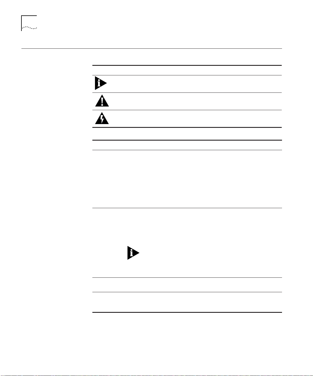
Conventions The following tables list conventions used throughout this guide:
Icon Notice Type Alerts you to...
Information note Important features or instructions
Caution Risk of personal safety, system damage, or loss
of data
Warning Risk of severe personal injury
Convention Description
Syntax Syntax means you must evaluate the syntax provided and
supply the appropriate values. Placeholders for values you
must supply appear in angle brackets. Example:
Enable RIPIP by using the following syntax:
SETDef ault !<por t> -RIPIP CONTrol =
Listen
In this example, you must supply a port number for
<port>.
Commands Command means you must enter the command exactly as
Screen displays This font represents information as it appears on the
The words enter
and type
shown in text and press the Return or Enter key. Example:
To remove the IP address, enter the following
command:
SETDef ault !0 -IP NETaddr = 0. 0.0.0
This guide always gives the full form of a command in
uppercase and lowercase letters. However, you can
abbreviate commands by entering only the uppercase
letters and the appropriate value. Commands are not
case-sensitive.
screen.
Enter means type something, and then press the Return or
Enter key. Do not press the Return or Enter key when an
instruction says type.
Page 17

Related Documents 3
Convention Description
[Key] names Key names appear in text in one of two ways:
■ Referred to by their labels, such as the Return key or
the Escape key
■ Written with brackets, such as [Return] or [Esc]
If you must press two or more keys simultaneously, the key
names are linked with a plus sign (+). Example:
Press [Ctrl]+[Alt]+[Del].
Menu commands
and buttons
Words in italicized
type
Words in boldface
type
Menu commands or button names appear in italics.
Example:
From the Help menu, select Contents.
Italics emphasize a point or denote new terms at the place
where they are defined in the text.
Bold text denotes key features.
Related Documents This section provides information on supporting documentation,
including:
■ 3Com Documents
■ Reference Documents
3Com Documents The following documents provide additional information on 3Com
products:
CoreBuilder 5000 Integrated System Hub Installation and Operation
Guide – Provides information on the installation, operation, and
configuration of the CoreBuilder 5000 hub. This guide also describes
the principal features of the CoreBuilder 5000 Fault-Tolerant Controller
Module.
CoreBuilder 5000 Distributed Management Module User Guide –
Provides information on the CoreBuilder 5000 Distributed
Management Module’s operation, installation, and configuration. This
guide also describes the software commands associated with the
Distributed Management Module.
CoreBuilder 5000 Distributed Management Module Commands
Guide – Describes each management command by providing details
on command format and use.
Page 18

4 About This Guide
For a complete list of 3Com documents, contact your 3Com
representative.
Reference Documents The following documents supply related background information:
Case, J., Fedor, M., Scoffstall, M., and J. Davin, The Simple Network
Management Protocol, RFC 1157, University of Tennessee at Knoxville,
Performance Systems International and the MIT Laboratory for
Computer Science, May 1990.
Rose, M., and K. McCloghrie, Structure and Identification of
Management Information for TCP/IP-based Internets, RFC 1155,
Performance Systems International and Hughes LAN Systems,
May 1990.
Page 19

1
INTRODUCTION
This chapter describes the features and components of 3Com
CoreBuilder
chapter contains the following sections:
■ FastModule Overview
■ FastModule Names
■ FastModule Features
■ Comparing FastModules to Bridges
■ FastModule Descriptions
■ FastModule Backplane Connections
5000 FastModules and their principles of operation. This
Page 20

1-2 CHAPTER 1: INTRODUCTION
FastModule Overview
CoreBuilder 5000 FastModules are high-performance LAN-switching
modules for the 3Com
®
CoreBuilder 5000 Integrated System Hub.
Based on the BRASICA Application Specific Integrated Circuit (ASIC),
the FastModule family extends switching from the backbone, enabling
you to provide your users with greater bandwidth, faster throughput,
and high-speed connections.
WorkGroup Solutions The 24-Port 10BASE-T FastModule provides switched 10BASE-T
connectivity to the workgroup and allows for one switched connection
to one of four CoreBuilder 5000 FastChannel backplane networks.
The 24-Port 10BASE-T FastModule with FX Downlink provides the same
switched 10BASE-T connectivity to the workgroup with an additional
100BASE-FX port for connection to Fast Ethernet backbone networks.
FastEthernet
Solutions
Support for collapsed Fast Ethernet backbones and large central server
farms is provided by the following FastModules:
■ 7-Port 100BASE-FX/TX FastModule – Provides five FX-port and two
TX-port switched Fast Ethernet connections to any one of four
CoreBuilder 5000 FastChannel backplane networks. When used in
conjunction with other CoreBuilder 5000 FastModules, this
FastModule lets you create backbone and floor configurations
based on shared and switched Fast Ethernet and Ethernet.
■ 7-Port 100BASE-TX FastModule – Provides seven TX-port switched
Fast Ethernet connections to any one of four CoreBuilder 5000
FastChannel backplane networks.
■ Aggregator/Downlink FastModule (with an optional FX, TX, or ATM
downlink port) – Consolidates traffic from up to four
CoreBuilder 5000 FastChannel backplane networks and three
Ethernet backplane segments within a single CoreBuilder 5000 hub.
The 100BASE-FX front panel port provides a downlink connection
into a switched Fast Ethernet backbone network. Three daughter
card options are available, providing one additional downlink port
using 100BASE-FX, 100BASE-TX, or 155 Mbps ATM technology.
Page 21

FastModule Names 1-3
FastModule Names Table 1-1 correlates each type of FastModule with its model number
and maps the full product name to the shortened name used
throughout this document:
Table 1-1 FastModule Names and Model Numbers
FastModule Name Model Number Shortened Name
CoreBuilder 5000 24-Port
10BASE-T FastModule
CoreBuilder 5000 24-Port
10BASE-T FastModule with FX
Downlink
CoreBuilder 5000 7-Port
100BASE-FX/TX FastModule
CoreBuilder 5000 7-Port
100BASE-TX FastModule
CoreBuilder 5000
Aggregator/Downlink FastModule
3C96524M-TP 24-Port
FastModule
3C96525M-TPFX 24-Port
FastModule with
FX Downlink
3C96507M-FXTX 7-Port FX/TX
FastModule
3C96507M-TX 7-Port TX
FastModule
3C96501M-BFX Downlink
FastModule
FastModule Features
For more information about Downlink FastModule option cards, refer
to the installation document that accompanies the option card.
FastModule features are described in the sections below:
■ Scalable Performance
■ Packet-Forwarding Modes
■ Outlet Port
■ Intelligent Flow Management
■ Full Duplex Support
■ Security
■ Resilient Links
■ Virtual LANs (VLANs)
■ PACE Technology
■ Spanning Tree Protocol
■ VLAN Server
Page 22

1-4 CHAPTER 1: INTRODUCTION
Scalable Performance Each FastModule is equipped with its own high performance switching
Application Specific Integrated Circuit (ASIC). 3Com BRASICA ASIC
technology provides scalable performance for switching on each port.
Packet-Forwarding
Modes
The 10 Mbps front panel ports on the 24-Port FastModule and 24-Port
FastModule with FX Downlink can operate in any of the following
forwarding modes:
■ Fast Forward – Frames are forwarded as soon as the destination
address is received and verified.
■ Fragment Free – A minimum of 64 bytes of the received frame is
buffered before the frame is forwarded.
■ Store and Forward – Received packets are buffered in their entirety
before forwarding. This ensures that only good frames are passed to
their destination.
■ Intelligent – The FastModule monitors the amount of error traffic
on the network and changes the forwarding mode accordingly.
Error traffic is defined as:
■ alignment errors
■ CRC errors
■ long frame errors
■ short events
■ collisions
If the FastModule detects:
■ less than 18 errors per second, it will operate in FastForward
mode.
■ more than 18 errors per second, it will operate in Store and
Forward mode until the number of errors returns to 0.
The 7-Port FX/TX FastModule, 7-Port TX FastModule, and Downlink
FastModule operate in Store and Forward mode only.
Page 23

FastModule Features 1-5
Outlet Port In the 24-Port FastModule only, you can designate any port to act as an
outlet port. The outlet port serves as an exit path for any packet that
arrives at a FastModule with an unknown destination address. By
default, the backplane port on the 24-Port FastModule (port 25) is
designated as the outlet port.
For more information about designating a outlet port, refer to Setting
Up VLANs on page 4-11.
Table 1-2
shows how a packet is processed when it arrives at the
FastModule, and delineates the difference between the action
performed by the 24-Port FastModule versus all other FastModules.
Table 1-2 FastModule Packet Forwarding Process
24-Port FastModule With
Packet Source
Any port EXCEPT
outlet port
(Unicast packet)
Any port EXCEPT
outlet port
(Unicast packet)
Any port EXCEPT
outlet port
(Unicast packet)
Any port EXCEPT
outlet port
(Multi/Broadcast
packet)
Outlet port
(Unicast packet)
Outlet port
(Unicast packet)
Outlet port
(Multi/Broadcast
packet)
Destination
Address
Unknown Forward to outlet port only Flood to all ports Flood to all ports
Same port as
source
address
Another port
(not outlet
port)
Not applicable Flood to all ports within
Unknown Filter (discard) N/A (no outlet port
Known on a
port (not
outlet port)
Not applicable Flood to all ports within
Bridging Mode Set to
Forward to Outlet
Filter (discard) Filter (discard) Filter (discard)
Forward to specific port
only
same VLAN as source port
Forward to specific port
only
specific VLAN
Action
24-Port FastModule With
Bridging Mode Set to
Forward to All
Forward to specific port
only
Flood to all ports within
same VLAN as source port
designation)
N/A (no outlet port
designation)
N/A (no outlet port
designation)
All Other
FastModules
Forward to
specific port only
Flood to all
ports within
same VLAN as
source port
N/A (no outlet
port designation)
N/A (no outlet
port designation)
N/A (no outlet
port designation)
Page 24

1-6 CHAPTER 1: INTRODUCTION
Intelligent Flow
Management
Intelligent Flow Management (IFM) is a congestion control mechanism
built into the FastModule. Congestion is caused by one or more devices
sending traffic to a FastModule port that is already busy.
IFM is available only on the FastModule front panel ports.
The FastModule contains both input and output packet buffers. While
congestion is rare, IFM is designed to alleviate problems when packet
buffers in the FastModule are full. IFM prevents packet loss by
preventing the transmitting device from sending any further packets
until the port is no longer congested.
If a packet arrives at a conventional switch that does not operate IFM,
and that port is congested (resulting in packet loss), the transmitting
device is unaware of this. The originating station may retransmit the
packets, effectively wasting bandwidth.
A FastModule using IFM senses congestion, and prevents packet loss by
inhibiting the transmitting device from transmitting the packet in the
first place. It does this by forcing the device to retransmit the packet
later. This “back-off” and retransmission occurs quickly (typically less
than 1 second) and is much faster than waiting for the transmitting
device to time-out.
There are two benefits:
■ The packet is transmitted quickly and successfully
■ The packet is only transmitted once, saving bandwidth
If the FastModule is connected to a repeated segment with local traffic,
and the FastModule invokes IFM on the repeated segment, the
FastModule would not only inhibit the devices transmitting to the
congested port, but also inhibit devices on the segment transmitting to
each other.
IFM does not operate in Full Duplex mode.
Full Duplex Support The FastModule provides full duplex capability on all front panel Fast
Ethernet ports. Full duplex capability allows frames to be transmitted
and received simultaneously, in effect doubling bandwidth available on
a link. Full duplex capability also supports 100BASE-FX cable runs of
up to 2 km.
Page 25

FastModule Features 1-7
Security Security is available on the 10 Mbps front panel ports of the 24-Port
FastModule and 24-Port FastModule with FX Downlink. FastModule
security prevents users from connecting unauthorized stations to the
network through the front panel ports. You enable security using the
FastModule Management Agent. When security is enabled on a port,
that port enters into a single address learning mode. This port is then
permitted to learn just a single Ethernet address. After that address is
learned, if the FastModule sees a different address on that port, the
port will be disabled. Until security is disabled, no other address can be
learned.
Resilient Links You can set up resilient links on FastModule front panel ports only.
Resilient links enable you to protect critical links and prevent wasteful
network downtime if the link fails. If a main communication link fails, a
standby duplicate link automatically takes over the task of the main
link. Each main and standby link pair is referred to as a resilient link
pair. The main and standby links must be set up on the same
FastModule.
Virtual LANs (VLANs) The Virtual LAN (VLAN) feature allows you to build your network
segments without being restricted by physical connections. A VLAN is
defined as a group of location- and topology-independent devices that
communicate as if they are on the same physical LAN.
Implementing VLANs on your network has three advantages:
■ When you move a workstation, minimal physical intervention is
required. Within the VLAN setup, you can configure a group of
devices on different floors in a building into a common
communications group. For example, if you move a workstation
from VLAN 1 to VLAN 2, you only need to know address
information for that device. The physical location of the port is
irrelevant.
■ Use of network resources becomes much more efficient. You can set
up each VLAN to contain only those devices which need to
communicate with each other.
■ Network security is enhanced. Devices within the same VLAN can
only communicate with member devices in the same VLAN. For
example, if a device in VLAN 1 needs to communicate with devices
in VLAN 2, you configure the device to cross the router between
VLAN 1 and VLAN 2.
Page 26

1-8 CHAPTER 1: INTRODUCTION
PACE Technology 3Com PACE Technology allows you to carry multimedia applications
using voice and video traffic over standard Ethernet and Fast Ethernet
LANs. PACE Technology provides the quality of service that these applications
require, reducing latency to a minimum and prioritizing the multimedia traffic.
Both multimedia and data traffic are improved considerably by:
■ Introducing an Ethernet switch into the LAN
■ Attaching each end-station to its own dedicated 10 Mbps switch
port
This removes any contention between different end-stations for the
Ethernet bandwidth. However, when 2-way traffic passes between an
end-station and the switch port, access to the bandwidth can still be
unfairly allocated to traffic in one direction, resulting in poor quality
video display. PACE Technology allocates the available bandwidth fairly
to traffic in each direction. You can use existing Ethernet adapters and
cabling to run high-quality multimedia sessions across the LAN.
You can enable PACE Technology to operate on the same
CoreBuilder 5000 backplane FastChannel between a maximum of two
FastModules installed in the same hub.
Spanning Tree
Protocol
Spanning Tree Protocol (STP) is part of the IEEE 802.1D bridging
specification that provides a system of allowing parallel paths for
network traffic while allowing:
■ A redundant path is disabled when a parallel main path is
operational
■ A redundant path is enabled if a parallel main path fails
Refer to Spanning Tree Protocol Overview in Chapter 2 for more
information.
VLAN Server The VLAN Server function allows you to create a VLAN Server database
from which you can set FastModule ports to automatically receive
assignment to a VLAN.
Refer to Using AutoSelect VLAN Mode
in Chapter 4.
Page 27

Comparing FastModules to Bridges 1-9
Comparing FastModules to Bridges
Table 1-3 shows FastModule operation compared to that of an IEEE
802.1D bridge.
ways except for those shown in Table 1-3
Table 1-3 Comparison of FastModules to Bridges
Feature
Address
Learning
Forwarding
Mode
Operation
when
packet
buffers full
Spanning
Tree
Action on
Unknown
Destination
Address
Database
size
Bridge and FastModule operation is identical in all
.
IEEE
802.1D
Bridge
All ports All ports (except
Store
and
forward
Discard
packets
Supported Supported Supported Supported
Flood all
ports
Variable 500 addresses 4080 addresses 4080 addresses
24-Port
FastModule
outlet when
Bridging Mode =
Forward to Outlet)
Fast Forward,
Fragment Free,
Store and
Forward, or
Intelligent
If enabled, IFM is
invoked to
suppress
transmissions at
source.
Forward to outlet
port only (when
Bridging Mode =
Forward to Outlet)
24-Port
FastModule w/
FX Downlink
All ports All ports
Fast Forward,
Fragment Free,
Store and
Forward, or
Intelligent
If enabled, IFM is
invoked to
suppress
transmissions at
source.
Flood all ports Flood all ports
All Other
FastModules
Store and
forward only
If enabled, IFM
is invoked to
suppress
transmissions at
source.
FastModule Descriptions
This section describes the following FastModules:
■ 24-Port FastModule
■ 24-Port FastModule with FX Downlink
■ 7-Port FX/TX FastModule
■ 7-Port TX FastModule
■ Aggregator/Downlink FastModule
Page 28
1-10 CHAPTER 1: INTRODUCTION
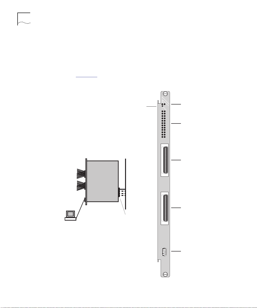
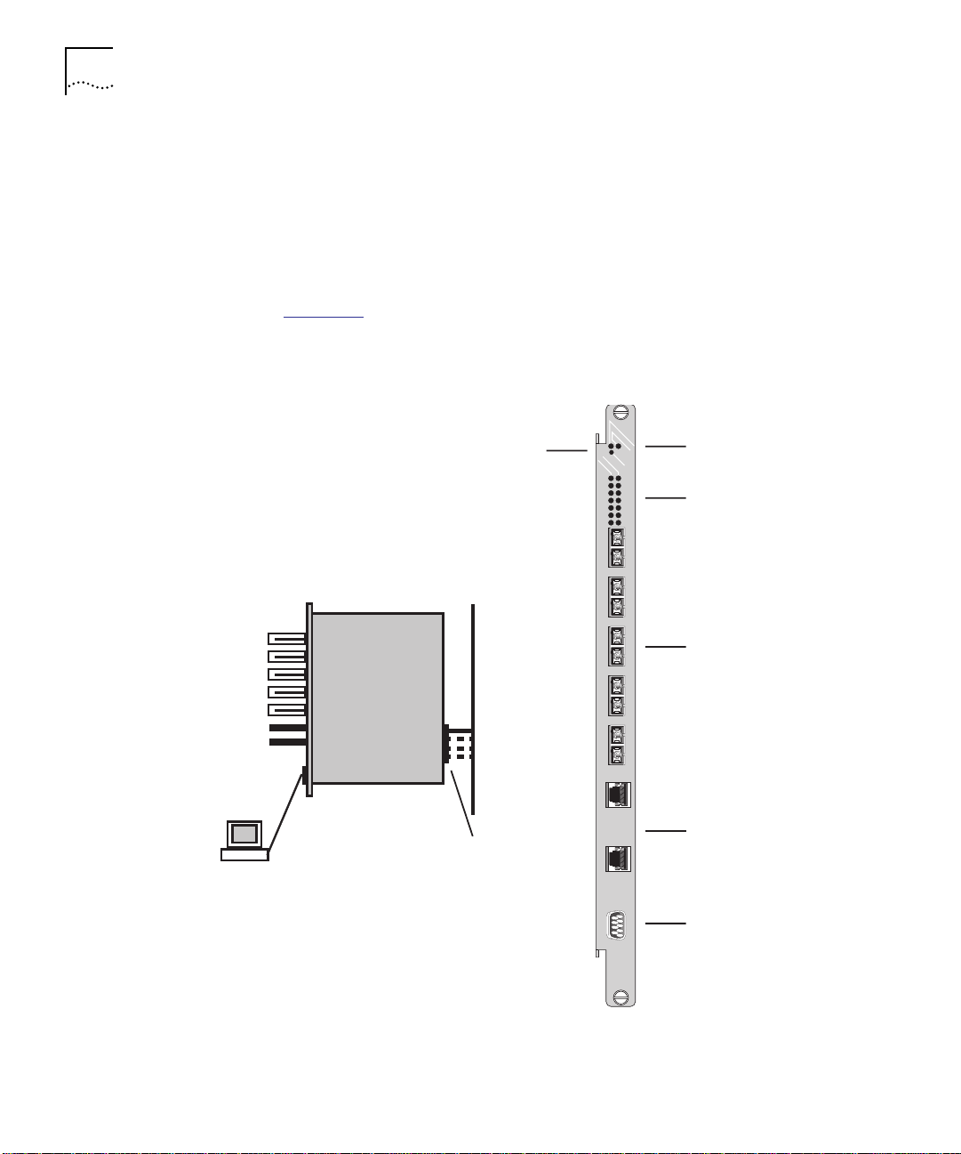
24-Port FastModule The CoreBuilder 5000 24-Port FastModule provides 24 switched
Ethernet ports for connecting network devices to any of four available
CoreBuilder 5000 FastChannel backplanes using shielded or unshielded
twisted-pair cabling. The 24 10BASE-T-compliant ports are provided
through two Telco connectors on the FastModule front panel.
10BASE-T
ports 1 to 12
10BASE-T
ports 13 to 24
Figure 1-1
24-Port FastModule
Out-of-band
console port
connection
shows the 24-Port FastModule.
SWITCH-STAT
Reset button
CoreBuilder 5000
FastChannel
Backplane
Backplane port 25
1
3
5
7
9
11
13
15
17
19
21
23
MOD-STAT
RESET
1X-12X
13X-24X
Module Status/
2
4
6
8
10
12
14
16
18
20
22
24
Switch Status LEDs
Port Status LEDs
Telco connector
(ports 1 to 12)
Telco connector
(ports 13 to 24)
Figure 1-1 24-Port FastModule
CONSOLE
Console port
6524M-TP
Page 29
FastModule Descriptions 1-11
24-Port FastModule
with FX Downlink
10BASE-T
ports 1 to 12
10BASE-T
ports 13 to 24
100BASE-FX
port 26
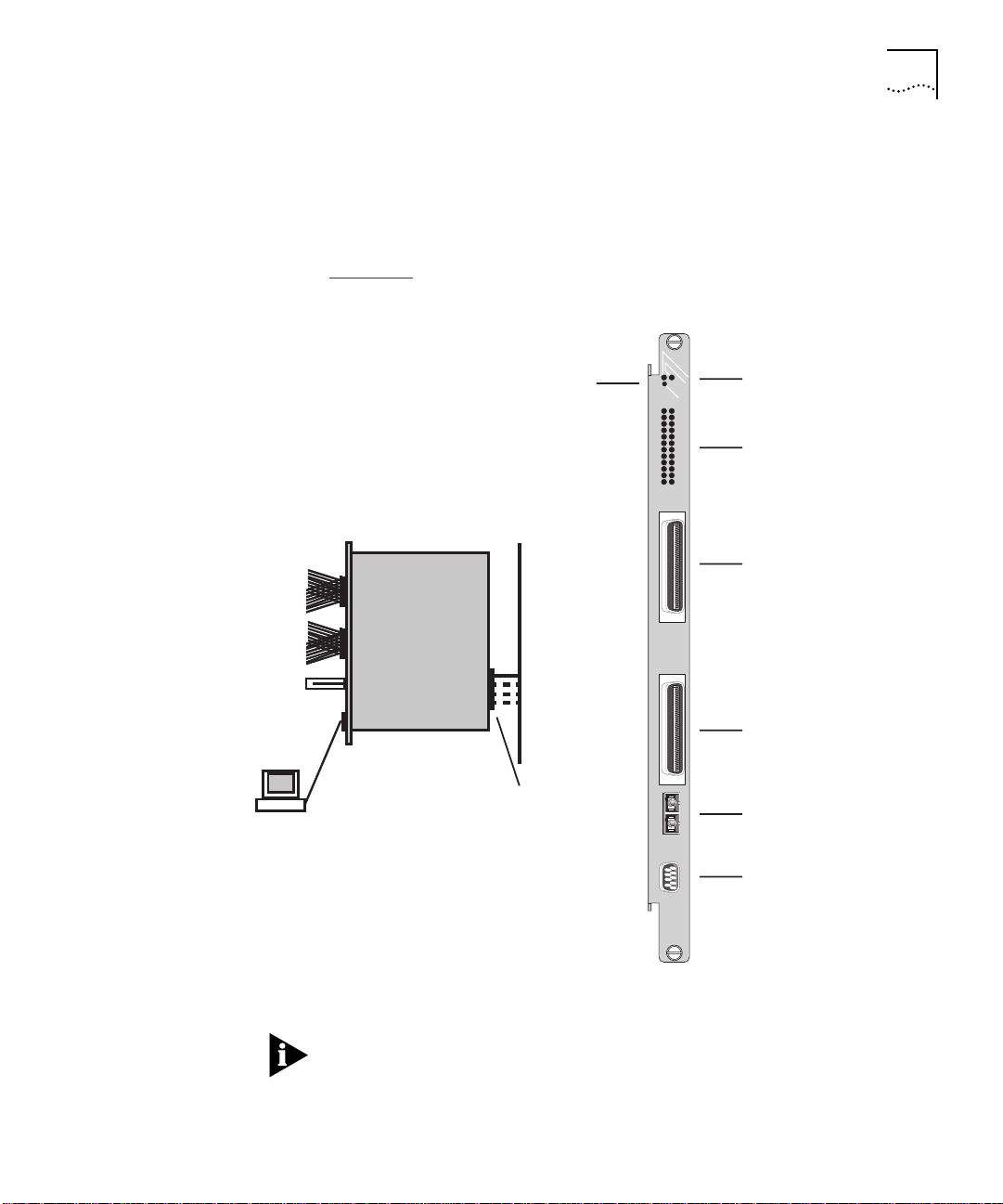
The 24-Port FastModule with FX Downlink is similar to the 24-Port
FastModule, and includes an additional switched 100BASE-FX
downlink port using an SC connector to connect to Fast Ethernet
backbone networks.
Figure 1-2
24-Port FastModule with FX Downlink
shows the 24-Port FastModule with FX Downlink front panel.
SWITCH-STAT
Reset button
CoreBuilder 5000
FastChannel
Backplane
MOD-STAT
RESET
1
2
3
4
5
6
7
8
10
9
11
12
13
14
15
16
17
18
19
20
21
22
23
24
1X-12X
13X-24X
Module Status/
Switch Status LEDs
Port Status LEDs
Telco connector
(ports 1 to 12)
Telco connector
(ports 13 to 24)
Out-of-band
console port
connection
Backplane port 25
100BASE-FX port 26
CONSOLE
Console port
6525M-TPFX
Figure 1-2 24-Port FastModule with FX Downlink
Using a 90° Telco connector cable on the bottom Telco port physically
prevents access to the 100BASE-FX port. Use either a 180° or 45°
cable. You can order a 45° cable through 3Com. Refer to Appendix A
for details.
Page 30
1-12 CHAPTER 1: INTRODUCTION
7-Port FX/TX
FastModule
100BASE-FX
ports 1 to 5
The CoreBuilder 5000 7-Port FX/TX FastModule provides:
■ Five 100BASE-FX ports using SC connectors which can be used as
downlink connections to the data center
■ Two 100BASE-TX ports using RJ-45 connectors which can be used
to provide dedicated 100 Mbps connections to workgroup servers
Figure 1-3
7-Port FX/TX FastModule
shows the 7-Port FX/TX FastModule front panel.
SWITCH-STAT
Reset button
CoreBuilder 5000
FastChannel
Backplane
PACKET
1
2
3
4
MOD-STAT
RESET
STATUS
1
2
3
4
5
6
7
Module Status/
Switch Status LEDs
Packet Activity/
Port Status LEDs
100BASE-FX ports 1 to 5
100BASE-TX
ports 6 to 7
Out-of-band
console port
Backplane port 8
connection
Figure 1-3 7-Port FX/TX FastModule
5
6X
100BASE-TX ports 6 to 7
7X
CONSOLE
Console port
6507M-TXFX
Page 31

FastModule Descriptions 1-13
7-Port TX
FastModule
100BASE-TX
ports 1 to 7
The CoreBuilder 5000 7-Port TX FastModule provides seven
100BASE-TX ports using RJ-45 connectors that allow dedicated
100 Mbps connections to workgroup servers.
Figure 1-4
7-Port TX FastModule
shows the 7-Port TX FastModule front panel.
SWITCH-STAT
Reset button
CoreBuilder 5000
FastChannel
Backplane
PACKET
1X
2X
3X
4X
5X
MOD-STAT
RESET
STATUS
1
2
3
4
5
6
7
Module Status/
Switch Status LEDs
Packet Activity/
Port Status LEDs
100BASE-TX ports 1 to 7
Out-of-band
console port
Backplane port 8
connection
Figure 1-4 7-Port TX FastModule
6X
7X
CONSOLE
Console port
6507M-TX
Page 32

1-14 CHAPTER 1: INTRODUCTION
Aggregator/Downlink
FastModule
100BASE-FX
port 1
The CoreBuilder 5000 Aggregator/Downlink FastModule is a
dual-width module that can consolidate traffic from four FastChannels
and three 10 Mbps Ethernet backplane segments.
The 100BASE-FX front panel port using an SC connector allows
downlink connections into a switched backbone. Three daughter card
options are available that provide an additional front panel downlink
port using 100BASE-FX, 100BASE-TX, or 155 Mbps ATM technology.
Figure 1-5
Downlink FastModule
shows the Aggregator/Downlink FastModule front panel.
SWITCH-STAT
Reset button
3 10 Mbps
Ethernet
backplanes
PACKET
TX
1
RX
MOD-STAT
RESET
STATUS
1
2
3
4
5
6
7
8
9
CONSOLE
Module Status/
Switch Status LEDs
Packet Activity/
Port Status LEDs
100BASE-FX port 1
Console port
Optional port 9
(FX, TX, ATM)
4 100 Mbps
FastChannel
backplanes
Out-of-band
console port
connection
Figure 1-5 Aggregator/Downlink FastModule
Option card
blanking plate
6501-BFX
Page 33

FastModule Backplane Connections 1-15
FastModule Backplane Connections
The FastModule connects to the CoreBuilder 5000 backplane which
supports four 100 Mbps FastChannel networks. In addition, the
Aggregator/ Downlink FastModule has access to three 10 Mbps
Ethernet networks. Table 1-4
describes the backplane configuration
options available for each FastModule type:
Table 1-4 CoreBuilder 5000 Backplane Configurations
FastModule Type Backplane Configuration
24-Port FastModule FastModule 100 MB backplane port is
24-Port FastModule with FX Downlink
7-Port FX/TX FastModule
7-Port TX FastModule
Aggregator/Downlink FastModule
(includes optional FX, TX, and ATM
daughter card)
switchable to any one of four 100 MB
FastChannels
Can connect to all four 100 MB
FastChannels and three 10 MB
backplane channels
The 24-Port FastModule, 24-Port FastModule with FX Downlink, 7-Port
FX/TX FastModule, and 7-Port TX FastModule provide one 100 MB
backplane port that you can assign to any one of four
CoreBuilder 5000 FastChannels, as shown in Figure 1-6
.
CoreBuilder 5000 backplane
FastEthernet 100Mbps
networks 1, 2, 3, 4
FastModule backplane port
(assignable to one of four
CoreBuilder 5000 FastEthernet
backplane networks)
Figure 1-6 FastModule Backplane Connections
Page 34

1-16 CHAPTER 1: INTRODUCTION
Table 1-5 describes FastModule port assignments:
Table 1-5 FastModule Backplane Port Assignments
Backplane
FastModule Type
24-Port FastModule 25 100 Any one of four
24-Port FastModule with
FX Downlink
7-Port FX/TX FastModule 8 100
7-Port TX FastModule 8 100
Port Number
25 100
Speed
(MB)
CoreBuilder
5000 Network
FastChannels
The Aggregator/Downlink FastModule provides seven backplane ports
that are hardwired to four FastChannel and three 10 Mbps Ethernet
networks in the CoreBuilder 5000 hub. These port assignments cannot
be changed. However, you can isolate the ports. The backplane port
architecture is shown in Figure 1-7
FastModule backplane ports
100 Mbps ports 2, 3, 4, 5
10 Mbps ports 6, 7, 8
.
CoreBuilder 5000
backplane networks
10 Mbps Ethernet
networks 5, 7, 8
100 Mbps Fast Ethernet
backplane networks 1, 2, 3, 4
Figure 1-7 Aggregator/Downlink FastModule Backplane Connections
Page 35

FastModule Backplane Connections 1-17
Table 1-6 describes the Aggregator/Downlink FastModule port
assignments:
Table 1-6 Aggregator/Downlink FastModule Backplane Port Assignments
FastModule
Backplane Port
2 100 FastChannel 1
3 100 FastChannel 2
4 100 FastChannel 3
5 100 FastChannel 4
6 10 Ethernet 5
7 10 Ethernet 7
8 10 Ethernet 8
Speed (MB)
CoreBuilder 5000
Network
Port 1 on the Aggregator/Downlink FastModule represents the front
panel 100BASE-FX port. The optional front panel port provided by the
daughter card is designated as port 9.
For information about the CoreBuilder 5000 backplane, refer to
CoreBuilder 5000 Slotting Considerations
on page 3-6.
Page 36

Page 37

FASTMODULE MANAGEMENT
2
OVERVIEW AND SETUP
This chapter describes FastModule management requirements and
tools and explains how to setup access to management tools.
This chapter contains the following sections:
■ FastModule Management Functions
■ Basic Management Tools
■ Using Advanced Management Tools
■ Setting Up Access for Basic Management
■ Configuring FMA for Management
■ Setting Up FMA Users
Page 38

2-2 CHAPTER 2: FASTMODULE MANAGEMENT OVERVIEW AND SETUP
FastModule Management Functions
Basic Management To o l s
Using the
FastModule
Management Agent
FastModule management tools allow you to perform the following
functions:
■ Configuration
■ Status and Performance Monitoring
■ Troubleshooting
This section identifies the basic management tools that are available for
you to manage CoreBuilder 5000 FastModules. FastModule basic
management tools include:
■ FastModule Management Agent (FMA)
■ Distributed Management Module (DMM) (includes Advanced DMM)
The FastModule Management Agent (FMA) management tool is built-in
to the FastModule software. FMA allows you to manage the following
FastModule tasks:
■ General switch and VLAN configuration
■ Status monitoring
■ Statistics generation and performance monitoring
Using the
Distributed
Management Module
■ Resetting and initializing the FastModule
You can access the FMA in either of two ways:
■ Connect a terminal directly to the console port of the FastModule
■ TELNET to the IP address for the FastModule
The 3Com CoreBuilder
™
5000 Distributed Management Module (DMM)
and Advanced DMM provide commands that allow you to assign
FastModule backplane ports to one of the CoreBuilder 5000 backplane
FastChannels or to isolate a backplane port.
You can access DMM in two ways:
■ Connect a terminal directly to the console port of the DMM
■ TELNET to the DMM (Refer to Setting Up Access for Basic
Management on page 2-5)
Page 39

Using Advanced Management Tools 2-3
Using Advanced Management Tools
Transcend Enterprise
Manager for UNIX
Operating Systems
Network management
platforms
3Com management
application
This section identifies the advanced management tools that are
available for managing CoreBuilder 5000 FastModules, including:
■ Transcend Enterprise Manager for UNIX
■ Transcend Enterprise Manager for Windows
■ Third-Party SNMP-Based Tools
3Com Transcend® Enterprise Manager for UNIX (TEM/UNIX) provides a
suite of advanced graphical tools for network management. Figure 2-1
illustrates the TEM/UNIX tools you can use to configure CoreBuilder
5000 FastModules.
SunOS, Solaris, HPUX, AIX
HP OpenView, SunNet Manager, NetView
Transcend Enterprise Manager for UNIX
Tools accessible from
network management
platform Tools menu
Figure 2-1 TEM/UNIX Tools for Configuring FastModules
You can access TEM/UNIX applications by:
■ Selecting the application directly from the Tools menu of the
Network Platform (for example, HP OpenView
■ By selecting a launch point from one TEM/UNIX application to
another.
You can access VLAN Manager from the Tools menu only.
CoreBuilder 5000
Manager
Device
View
Alternative launch points
Bridge
Management
®
)
VLAN
Manager
Page 40

2-4 CHAPTER 2: FASTMODULE MANAGEMENT OVERVIEW AND SETUP
Transcend Enterprise
Manager for
Windows
3Com Transcend Enterprise Manager for Windows (TEM/Windows)
provides a suite of advanced graphical tools for network management.
Figure 2-2
illustrates the TEM/Windows tools that you can use to
configure CoreBuilder 5000 FastModules.
Operating Systems
Network management
platforms
3Com management
application
Tools accessible from
network management
platform Tools menu
CoreBuilder 5000
Manager
Device
View
Figure 2-2 TEM/Windows Tools for Configuring FastModules
Windows 95, Windows NT
HP OpenView for Windows
Transcend Enterprise Manager for Windows
Bridge
Management
Alternative launch point
VLAN
Manager
Third-Party
SNMP-Based Tools
You can access TEM/Windows applications by:
■ Selecting the application directly from the Tools menu of the
Network Platform (for example, HP OpenView)
■ By selecting a launch point from one TEM/Window application to
another.
You can access VLAN Manager from the Tools menu only.
After you set up the FastModule IP parameters, you can use any SNMP
network manager for in-band management (if the Management
Information Base (MIB) is correctly installed on your network
management station).
Page 41

Setting Up Access for Basic Management 2-5
Setting Up Access for Basic Management
Setting Up FMA
Access
This section provides procedures you must follow to set up access to the
FastModule Management Agent (FMA) and DMM management tools.
This section includes the following topics:
■ Setting Up FMA Access
■ Connecting the FastModule to the Backplane
■ Setting Up DMM Access
You can access FMA by:
■ Direct terminal access
■ TELNET access
Setting Up Direct Terminal Access to the FMA
To set up a direct terminal connection to the FMA, connect a
VT100 terminal (or workstation with terminal emulation software) to
the FastModule serial port. You can connect a terminal directly, or
remotely through a modem.
The default FastModule serial port settings are set to:
■ Character Size – 8
■ Parity – None
■ Stop Bit – 1
The terminal connected to the serial port on the FastModule must be
configured with the same settings as listed above. This procedure is
described in the documentation that accompanies your terminal
application. If you enabled auto-configuration for the FastModule, the
terminal’s line speed (baud rate) will be detected automatically. The
maximum baud rate the auto-configuration detects is 19200 baud.
After you establish access to the FMA, you can use the Serial Port
Setup screen to change serial port parameters. For more information,
refer to Setting Up the Serial Port
on page 3-30.
Appropriate cables are available from your local supplier. If you need to
make your own cables, pin-outs are detailed in Appendix A.
The serial port requires a female 9-pin crossover cable.
Page 42

2-6 CHAPTER 2: FASTMODULE MANAGEMENT OVERVIEW AND SETUP
Setting Up TELNET Access to the FMA
Connecting the
FastModule to the
Backplane
After you specify the FastModule IP parameters, you can use any
TELNET application that emulates a DEC VT100
®
terminal to access
FMA over the network.
To begin a TELNET session, specify the IP address of the FastModule.
For example:
TELNET 185.104.1 0.2
For more information on using TELNET, refer to the documentation
supplied with your TELNET application.
Up to three active TELNET sessions can access the FMA concurrently. If
a connection to a TELNET session is lost inadvertently, the connection
is closed by the FastModule after 30 minutes of inactivity.
Use DMM commands to set the backplane port of the FastModule to
the CoreBuilder 5000 backplane FastChannels.
Your options for setting the backplane port assignment depend on the
type of FastModule:
■ Downlink FastModule – Upon installation, all Downlink
FastModule backplane ports are isolated from their hardwired
backplane channels (see Table 2-1
). These channel assignments
cannot be changed. You can only enable or isolate Downlink
FastModule backplane ports.
■ All other FastModules – You can assign FastModule backplane
ports to:
■ Backplane channel
■ Isolated mode
Page 43

Setting Up Access for Basic Management 2-7
Table 2-1 describes the backplane port connections of each
FastModule type:
Table 2-1 Backplane Port Connections
FastModule
Type
24-Port
FastModule
24-Port
FastModule with
FX Downlink
7-Port FX/TX
FastModule
7-Port TX
FastModule
Downlink
FastModule (All
Types)
Backplane Port Types
100 MB backplane port
switchable to any of four
100 MB FastChannels
Four 100 MB backplane
ports are assigned to
backplane FastChannels
Three 10 MB backplane
ports are assigned to
standard Ethernet channels
FastModule
Port
Number
25 FastChannel
25 FastChannel
8 FastChannel
8 FastChannel
2, 3, 4, and 5FastChannels
6, 7, and 8 Standard Ethernet
Valid Backplane
Channel
Assignments
1, 2, 3, or 4
1, 2, 3, or 4
1, 2, 3, or 4
1, 2, 3, or 4
1, 2, 3, and 4
channels 5, 7,
and 8
Assigning a Backplane Port to a Backplane Channel
To assign the FastModule backplane port to one of the backplane
channels, use the following DMM command:
Refer to Ta bl e 2-1
set por t
■ slot – CoreBuilder 5000 slot number that the FastModule is
for backplane port assignment restrictions.
slot.port
network {fast_ether_1 ... 4}
{ethernet_ 5, 7, 8}
installed in
■ port – FastModule backplane port number (see Table 2-1)
For example, the following command sets the backplane port on a
24-Port FastModule installed in slot 3 to FastChannel_2:
CB50 00> set po rt 3.25 network fa st_ether _2
Page 44

2-8 CHAPTER 2: FASTMODULE MANAGEMENT OVERVIEW AND SETUP
To save configuration changes, use the SAVE command. For example,
the following command saves all configuration changes:
CB50 00> save all
If you do not save module settings, you may lose configuration data.
Isolating a Backplane Port
You can isolate a FastModule backplane port from its assigned
backplane network by using the following command:
set por t
slot.port
network isolated_ {1. ..7}
For example, the following command isolates port 5 on a Downlink
FastModule installed in slot 3 from the default network.
CB50 00> set po rt 3.5 networ k isolated_4
To save configuration changes, use the SAVE command. For example,
the following command saves all configuration changes:
CB50 00> save all
Setting Up DMM
Access
If you do not save module settings, you may lose configuration data.
You can access the DMM by:
■ Direct terminal access
■ TELNET access
Setting Up Direct Terminal Access to the DMM
Refer to the Distributed Management Module User Guide for
procedures to set up a direct terminal connection to the DMM.
Configuring TELNET Access to the DMM
This section describes how to configure in-band access to the DMM,
which allows you to manage the CoreBuilder 5000 hub from a remote
terminal or SNMP manager such as the 3Com Transcend Enterprise
Manager application.
This procedure is not necessary if you have already established IP
connectivity to the DMM through another module installed in the
CoreBuilder 5000 hub.
Page 45

Setting Up Access for Basic Management 2-9
The FastModule has embedded network connectivity to the DMM
across the hub management channel.
Before you begin this procedure, you must have assigned FastModule
backplane ports to a backplane network as described in Connecting the
FastModule to the Backplane on page 2-6.
To configure in-band access to the DMM:
1 Log in to the DMM using a terminal connected to one of the serial
ports. The default login name is system (all lowercase) with a blank
password. For example:
Logi n: sy stem
Passwo rd: [press Enter]
2 Make sure that the device you plan to use for remote management has
connectivity to the network you assigned earlier to the FastModule.
For example, you could assign a media module port to the selected
network and connect the port to a router that has connectivity to your
SNMP management workstation.
3 Set the IP subnet mask for the selected network. For example:
CB50 00> set ip subnet_ma sk ff.ff.ff.0 fa st_ether_ 2
4 Set the IP address for the selected network. For example:
CB50 00> set ip ip_address 185.1 04.10.2 f ast_ether_2
5 Set the DMM IP default gateway for the selected network. For
example:
CB50 00> set ip default_g ateway 185. 104.10.7 f ast_ether_2
6 Use the SET MODULE INTERFACE command to enable the network
monitoring interface. For example:
CB50 00> set module 4.1 interfac e enable
You can use the SHOW INTERFACE command to display information
about the FastModule, including the slot.subslot location.
Page 46

2-10 CHAPTER 2: FASTMODULE MANAGEMENT OVERVIEW AND SETUP
7 Set the default gateway for the selected network to be the active
default gateway for the DMM. For example:
CB50 00> set ip active_de fault_gateway 1 85.104.10 .7
8 Use the SHOW IP command to verify the subnet mask, IP address,
default gateway, and active default gateway.
9 If you plan to use an SNMP manager to manage the CoreBuilder 5000
hub, use the SET COMMUNITY command to create an entry for the
manager in the DMM community table.
The following example creates a community named mgt. This
community provides all access privileges for an SNMP manager with the
IP address 185.104.10.9:
CB50 00> set community mgt 185.104.10.9 all
10 Use the SAVE ALL command to save all changes.
Page 47

Configuring FMA for Management 2-11
Configuring FMA for Management
The following sections explain how to access the FMA screens for the
CoreBuilder 5000 FastModules. Refer to Figure 2-3
to locate the screens
you require.
Figure 2-3 FMA Screen Map
This section describes:
■ Logging On
■ Using the FMA Management Setup Screen
■ Logging Off
■ Auto Logoff
Page 48

2-12 CHAPTER 2: FASTMODULE MANAGEMENT OVERVIEW AND SETUP
Logging On To log o n to F M A :
1 From the FMA banner screen, press Return to display the Logon screen
shown in Figure 2-4
Figure 2-4 FMA Logon Screen
.
2 Enter your user name and password. They are both case-sensitive.
■ If you are logging on for the first time (after installation or
initialization), use a default user name and password to match your
access requirements. We recommend you that you use the default
user security so that you can access all functions. The defaults are
shown in Ta ble 2 -2
■ If you were assigned a user name and password, enter them now.
Table 2-2 Default Users
Default
User Name
monitor monitor monitor - This user can view
manager manager manager - This user can
security security security - This user can access
Password Access Level
.
but not change, a subset of
the manageable parameters
access and change the
operational parameters but
not special/security features
and change all manageable
parameters
Page 49

Configuring FMA for Management 2-13
Assigning a Security Level
When you have successfully logged on to FMA, the Main menu
appears as shown in Figure 2-5
.
Figure 2-5 FMA Main Menu
From the Main menu, you can select the options you need to manage
the module.
Access to options depends on the access level you have been assigned.
Access rights to the FMA screens for the FastModule are listed in
Table 2-2
If you are a user with
.
security access level, and are using the
management facility for the first time, you should:
■ Assign a new password for the security access level as described in
Editing User Details
■ Assign new passwords for the other default users as described in
Editing User Details
■ Set up user names and passwords for any other users, and assign
on page 2-21.
on page 2-21.
each user an appropriate security level as described in Creating a
New User on page 2-19.
Page 50

2-14 CHAPTER 2: FASTMODULE MANAGEMENT OVERVIEW AND SETUP
Keyboard Shortcuts
You can press Ctrl-K to display a Help screen listing keyboard shortcuts
you can use to navigate the FMA screens. The help screen is shown in
Figure 2-6
.
Using the FMA
Management Setup
Screen
Figure 2-6 Help Screen
The Switch Management Setup screen allows you to configure IP and
IPX parameters for the FastModule. This screen also allows you to
display a screen for setting up traps.
The DMM/ADMM does not provide IPX support.
If you change the IP parameters using this screen, the changes do not
take effect until you reset the FastModule. Refer to Resetting the
FastModule on page 6-4. Changes made using the SETUP TRAPS and
SERIAL PORT buttons take effect immediately.
To access the Setup screen, from the FMA Main menu screen, select the
MANAGEMENT SETUP option. The Switch Management Setup screen
appears as shown in Figure 2-7
.
Page 51

Configuring FMA for Management 2-15
Figure 2-7 Switch Management Setup Screen
The screen shows the following:
MAC Address – The FastModule read-only MAC address required for
management.
Power On Self Test (POST) Type – Normal/Extended Use this field to
determine the type of self-test that the FastModule carries out when it
is powered up. If this field is set to Normal, the FastModule executes a
basic confidence check lasting approximately 10 seconds. If this field is
set to Extended, the FastModule executes a full set of dynamic memory
tests which may take up to 90 seconds to complete.
Device IP Address – If using IP, you must specify a unique IP address
in this field. If you do not know your IP address, consult your network
administrator. You can change the IP address using this field. For the
change to take effect, you must reset the FastModule.
Device SubNet Mask – If using IP, type a suitable network mask. For a
class B IP address, 255.255.0.0 is suitable. For more information, see your
network administrator. You can change the Device SubNet Mask using
this field. For the change to take effect, you must reset the FastModule.
Page 52

2-16 CHAPTER 2: FASTMODULE MANAGEMENT OVERVIEW AND SETUP
Default Router – If a default router exists on your network, type the
IP address here. You can change the Device Router IP address using this
field. For the change to take effect, you must reset the FastModule.
BOOTP Select – Enabled/Disabled If BOOTP is enabled and you have a
BOOTP server on your network, an IP address is automatically mapped
to the FastModule when it is first powered on. In addition to mapping
an IP address, BOOTP can assign the subnet mask and default router.
Using a BOOTP server avoids having to configure devices individually.
If you want to access your BootP server over the backplane, you must
first establish backplane connectivity for the FastModule. Refer to the
CoreBuilder 5000 FastModule Quick Start and Reference for
information on setting the FastModule backplane port to a
CoreBuilder 5000 network.
The following entries are provided on the Switch Management Setup
screen (one for each data link layer protocol that can be used by IPX):
IPX Network – This field shows the address of the network for this
protocol. This address is learned automatically from the local IPX router
or Netware file server, and you do not need to change it.
Node – This read-only field shows the node address of the FastModule
which is learned automatically.
Status – Enabled/Disabled If this field is set to Enabled, the FastModule
supports SNMP over IPX. For security, set this field to Disabled if you do
not require SNMP over IPX.
Data Link Protocol – This field shows the name of the IPX data link
layer protocol.
SETUP TRAPS – Select this button to display the setup screen for trap
parameters. Trap Setup is described in Setting Up Traps
on page 3-29.
SERIAL PORT – Select this button to display the setup screen for serial
port parameters. Trap Setup is described in Setting Up the Serial Port
on page 3-30.
Logging Off After you finish using the facility, select the Logoff option from the
bottom of the Main menu. If you accessed the facility using a TELNET
session or modem connection, the connection closes automatically.
Page 53

Configuring FMA for Management 2-17
Auto Logoff The built-in security timeout on the FMA interface works as follows:
■ If you do not press any keys for 30 minutes, FMA warns you that
the inactivity timer expires.
■ If you do not press a key within 10 seconds, the timer expires and
the screen becomes locked. Any displayed statistics continue to be
updated.
■ When you next press a key, the display changes to the Auto Logout
screen shown in Figure 2-8
.
Figure 2-8 Auto Logout Screen
The Auto Logout screen requests you to enter your password again. If
the password is correctly entered, the screen that was active when the
timer expired is displayed. If you make a mistake entering your
password, the Logon screen reappears.
Page 54

2-18 CHAPTER 2: FASTMODULE MANAGEMENT OVERVIEW AND SETUP
Setting Up FMA Users
The User Access Levels screen allows you to create, edit, delete, and
view users.
From the Main menu, select USER ACCESS LEVELS. The User Access
Levels screen appears as shown in Figure 2-9
Figure 2-9 User Access Levels screen
.
From the User Access Levels screen you can access:
■ LOCAL SECURITY screen – Allows you to set up access levels for
users on the FastModule.
■ CREATE USER screen – In addition to the default users set up on
the FastModule, you can add up to ten new users.
■ DELETE USERS screen – Allows you to delete users from the
FastModule. The default users cannot be deleted. You can also use
this screen to view the current list of users.
■ EDIT USER screen – Allows you to change your own password
and community string. You cannot change details for other users.
Page 55

Creating a New User To create a new user:
1 Select the CREATE USER option. The Create User screen appears as
shown in Figure 2-10
Setting Up FMA Users 2-19
.
Figure 2-10 Create User Screen
2 Complete the fields and assign an access level for the new user.
3 After you complete the form, select OK.
The Create User screen contains the following fields:
User Name – Type in the name of this new user. The name can consist
of up to 10 characters and is case-sensitive.
Password – Type in the password for this new user. The password can
consist of up to 10 characters and is case-sensitive. For security reasons,
the password is not displayed on screen.
Access Level – Assign an access level for this new user, as follows:
■ monitor – Access to view, but not change a subset of the
manageable parameters of the FastModule
■ secure monitor – Same as monitor
■ manager – Access to all the manageable parameters of the
FastModule, except security features
Page 56

2-20 CHAPTER 2: FASTMODULE MANAGEMENT OVERVIEW AND SETUP
■ specialist – Same as manager
■ security – Access to all manageable parameters of the
FastModule
Community String – By default a community string identical to the
user name is generated. You can change this to any text string of
32 characters or less. The community string is only needed for SNMP
access. If you are using a remote SNMP network manager, the
community string specified in the Network Manager’s database must be
the same as that for the device.
Community strings greater than 32 characters are automatically
truncated.
Deleting a User To delete a user:
1 Select the DELETE USER option. The Delete Users screen appears as
shown in Figure 2-11
.
Figure 2-11 Delete Users Screen
2 Use the spacebar to highlight the user that you want to delete. Note
that you cannot delete default users or the current user (that is,
yourself).
3 Select DELETE USERS.
Page 57

Editing User Details To edit user details:
1 Select the EDIT USER option. The Edit User screen appears as shown in
Figure 2-12
Figure 2-12 Edit User Screen
.
Setting Up FMA Users 2-21
2 Complete the fields as required.
3 After you complete the changes, select OK.
The Edit User screen contains the following fields:
User Name – This read-only field shows the name of the user that you
are logged in as. This field cannot be changed; if you need to change
the user name, you must delete this user and create a new one.
Old Password – Type the old password for this user.
New Password – Type a new password for this user.
Confirm Password – Retype the new password into this field.
Do not lose your password. If you forget your password while logged
out of the FastModule FMA interface, contact your 3Com technical
support representative.
Community String – Type a new community string into this field.
Community strings greater than 32 characters are automatically
truncated.
Page 58

2-22 CHAPTER 2: FASTMODULE MANAGEMENT OVERVIEW AND SETUP
Viewing Users Use the Delete Users screen to display the list of current users. To view
users:
1 Select the DELETE USER option.
2 Select CANCEL to exit.
Assigning Local
Security
The local security screen shows a matrix of options for access method
(Serial Port, Remote TELNET, Community-SNMP) and access level.
To assign local security:
1 Select the LOCAL SECURITY option. The Local Security screen appears
as shown in Figure 2-13
Figure 2-13 Switch Local Security Screen
.
2 Complete the fields as required.
3 After you complete the form, select OK.
Options for the access methods are:
Serial Port Enabled/Disabled – To prevent access to the management
facilities through the serial port, disable access to the facility for each
access level. Serial Port access for Security is enabled and cannot be
changed. This prevents accidental disabling of all access levels from
management.
Page 59

Setting Up FMA Users 2-23
Remote TELNET Enabled/Disabled – TELNET is an insecure protocol.
You may want to disable all access to the management facilities using
TELNET if important or sensitive data exists on your network.
Community SNMP Enabled/Disabled – The FastModule can be
managed through SNMP using a remote network manager.
Community SNMP includes some simple security features, but it is an
insecure protocol. You may want to disable all access to the
management facilities if important or sensitive data exists on your
network.
Page 60

Page 61

BASIC FASTMODULE
3
CONFIGURATION
This chapter describes how to use basic management tools to configure
FastModule, hub, and general switching parameters.
You can use advanced management tools, such as Transcend
Enterprise Manager (for UNIX or Windows) to configure your
FastModule. Refer to Using Advanced Management Tools
information.
This chapter contains the following sections:
■ Basic Configuration Guidelines
■ Configuring General Switch Parameters
■ Choosing a Switch Management Level
■ Setting Up the FastModule
■ Setting Up FastModule Ports
■ Switch Database (SDB) Description
for more
■ Setting Up Resilient Links
■ Setting Up Traps
■ Setting Up the Serial Port
Page 62

3-2 CHAPTER 3: BASIC FASTMODULE CONFIGURATION
0
Basic Configuration Guidelines
Basic Configuration
Examples
This section provides information that you should keep in mind as you
develop your FastModule configuration. This section includes:
■ Basic Configuration Examples
■ Startup Defaults
■ Configuration Rules
The following illustrations show some typical FastModule applications
for your network.
Figure 3-1
shows how the FastModule fits into a corporate network
with a Fast Ethernet infrastructure. 24-Port FastModules are positioned
on each floor and servers are centralized with a 7-Port FX/TX
FastModule.
Repeater
24-Port FastModule
with FX Downlink
24-Port FastModule
100 Mbps
Downlink
7-Port FX/TX
FastModule
100 Mbps
Server
100 Mbps
Figure 3-1 Configuration Example 1
Superstack II Switch 100
Server
Page 63
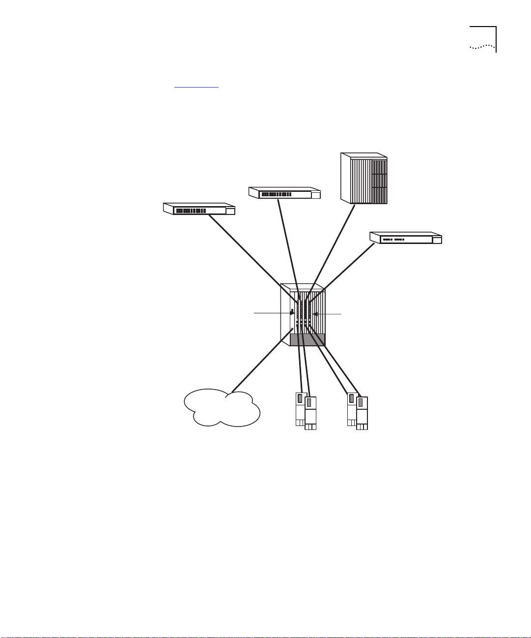
Basic Configuration Guidelines 3-3
Figure 3-2 shows four 7-Port FX/TX FastModules that provide 100 Mbps
server connections to end users attached to network devices. An
Aggregator/Downlink FastModule consolidates traffic from four
FastChannel backplane networks onto an ATM downlink.
CoreBuilder 5000 10-Slot hub
Superstack II Switch 1000
Superstack II Switch 1000
Superstack II Switch 3000
Downlink FastModule
100 Mbps
Downlink
ATM
Figure 3-2 Configuration Example 2
Four 7-Port FX/TX FastModules
(each connected to a separate
backplane FastChannel)
100 Mbps server
connections
Servers
Page 64

3-4 CHAPTER 3: BASIC FASTMODULE CONFIGURATION
Startup Defaults Table 3-1 shows the default settings of a FastModule as it is shipped
from 3Com.
Table 3-1 Startup Default Settings
Port Status Enabled
Serial port ■ Character size – 8
■ Parity – None
■ Stop bit – 1
■ Line speed – Auto detect
Port Enable
Status
Forwarding Mode ■ 24-Port FastModule – Fast Forward
Intelligent Flow
Management
(IFM)
PACE Technology Unit: Disabled
Switch Database No Entries
Backplane port Aggregator/Downlink FastModule – Isolated on all backplane
VLANs All ports in VLAN 1. The default VLAN is the only VLAN which
VLAN
Configuration
Mode
Full Duplex Off
Power On Self
Test (POST)
BootP Enabled
System Gauge
(broadcast)
On
■ 24-Port FastModule with FX Downlink – Fast Forward
■ All other FastModules – Store and Forward
Enabled on front panel ports
Not available on backplane ports
Port: Use Default
channels
All other FastModules – Isolated
allows access to the FastModule Management Agent.
Unit: Port
Port: Use Default
Normal
Enabled
■ High threshold: 20%
– No action
■ Low threshold: 10%
– No action
Page 65

Basic Configuration Guidelines 3-5
Table 3-1 Startup Default Settings (continued)
System Gauge
(errors)
Enabled
■ High threshold: 2%
– Notify
■ Low threshold: 1%
– No action
System Gauge
(traffic)
Enabled
■ High threshold: 85%
– No action
■ Low threshold: 50%
– No action
System Gauge
(frames
forwarded)
Enabled
■ High threshold: 85%
– No action
■ Low threshold: 50%
– No action
Spanning Tree
Off
Protocol
RMON 1 Ethernet Statistics session per port/VLAN monitoring the
Ethernet repeater traffic
3 Stats History sessions on the outlet port (24 Port FastModule
only) and 3 on the default VLAN
1 Host Table session on the default VLAN
1 Matrix Table session on the default VLAN
No default topN groups
4 default Alarms per port
Default Events for use with the alarm system
Configuration Rules This section identifies configuration rules in the following areas:
■ CoreBuilder 5000 Slotting Considerations
■ Fast Ethernet Considerations
■ Full Duplex Considerations
■ Server Considerations
Page 66

3-6 CHAPTER 3: BASIC FASTMODULE CONFIGURATION
CoreBuilder 5000 Slotting Considerations
The CoreBuilder 5000 hub has the capacity for four Fast Ethernet
channels (FastChannels). When you use assign a FastModule backplane
port to a CoreBuilder 5000 FastChannel, one or more backplane
channels are disabled.
Table 3-2
lists the backplane channels that become unavailable for each
FastChannel assignment.
Table 3-2 FastChannel Assignment Effect on Backplane Channels
Assigning
Backplane Port to
FastChannel
1 2 7, 8, and 9 4 and 5
2 1 and 2 5, 6, 10, and 11 3 and 6
3 1 1, 2, 3, and 4 1 and 2
4 3 13, 14, and 15 7 and 8
Disables
CoreBuilder 5000
Ethernet Channel
Disables ONline
Token Ring
Channel
Disables
ONline FDDI
Channel
CAUTION: If you enable more than one Aggregator/Downlink
Fastmodule on the same FastChannel and you do not have STP
enabled, a network loop can occur, severely affecting network
operation.
Fast Ethernet Considerations
The topology rules for Fast Ethernet (100 Mbps) differ slightly from
those for 10 Mbps Ethernet. The key topology rules are:
■ Maximum UTP cable length is 100 m (328 ft.) over category 5 cable.
■ A 412 m (1352 ft.) fiber run is allowed for connecting switch to
switch, or end-station to switch, using standards-compliant
half-duplex 100BASE-FX.
■ A total network span of 325 m (1066 ft.) is allowed in
single-repeater topologies.
Full Duplex Considerations
FastModules provide full duplex support for all front panel 100 Mbps
ports. Full duplex support allows frames to be transmitted and received
simultaneously and, in effect, doubles the bandwidth available on a link.
Page 67

Configuring General Switch Parameters 3-7
With full duplex support, the topology rules are:
■ Maximum UTP cable length is 100 m (328 ft.) over category 5 cable.
■ A 2 km (6562 ft.) fiber run is allowed for connecting switch to
switch, or end-station to switch.
■ Intelligent Flow Management is not supported if Full Duplex is
enabled.
Server Considerations
When integrating the FastModule into your network, the following
notes on server connections can help ensure that it is operating at
maximum efficiency:
■ You should ...
... connect any local server to the FastModule using a 100 Mbps port.
■ If that is not possible ...
... connect the local server to a dedicated 10 Mbps port.
Configuring General Switch Parameters
■ If that is not possible and the local server is connected to a repeated
segment where the traffic is mainly local to that segment ...
... disable Intelligent Flow Management (IFM) on the port to which the
repeater is connected.
If the FastModule is connected to a repeated segment with local traffic,
and the FastModule invokes IFM on the repeated segment, the
FastModule would not only inhibit the devices transmitting to the
congested port, but also inhibit devices on the segment transmitting to
each other. For more information about IFM, refer to Intelligent Flow
Management on page 1-6.
Switch parameters for the FastModule include:
■ Unit Parameters
■ Port Parameters
■ VLAN Parameters
This section explains how to configure unit and port parameters for
your FastModule. Refer to Chapter 4, Advanced Configuration
, for
information on VLAN parameters.
Page 68

3-8 CHAPTER 3: BASIC FASTMODULE CONFIGURATION
Choosing a Switch Management Level
The Switch Management screen enables you to select port, unit, or
VLAN configuration screens.
To select the type of parameters you want to configure:
1 From the Main menu, select SWITCH MANAGEMENT. The Switch
Management screen appears as shown in Figure 3-3
Figure 3-3 Switch Management Screen – Port Level
.
2 Select the management level at which you wish to configure the
FastModule. If you choose:
■ Port – The screen that appears is similar to that shown in Figure 3-3
and all operations invoked from this screen will configure an
individual port that you identify.
■ Unit – The screen that appears is similar to the example shown in
Figure 3-4
and all operations that you initialize from this screen will
configure to the FastModule.
Page 69

Choosing a Switch Management Level 3-9
Figure 3-4 Switch Management Screen – Unit Level
■ VLAN – The screen that appears is similar to that shown in
Figure 3-5
and from here you can access the VLAN Setup screen.
Figure 3-5 Switch Management Screen – VLAN Level
3 Specify the Port ID if you are configuring port parameters. The Port ID
parameter is defined below:
Port ID port range – If you have chosen to manage a FastModule port,
type the particular port number into this field before selecting the next
screen. Ta ble 3 -3
shows valid port IDs for each FastModule.
Page 70

3-10 CHAPTER 3: BASIC FASTMODULE CONFIGURATION
Table 3-3 FastModule Port IDs
FastModule Type Front Panel Port Number
24-Port FastModule 1 to 24 for the 10BASE-T ports 25
24-Port
FastModule with
FX Downlink
7-Port FXTX
FastModule
7-Port TX
FastModule
Aggregator/Downlink
FastModule
4 Select the button for the activity you wish to perform. Valid options are:
STP (Port and VLAN only) – Use this button to display the Spanning
Tree Protocol screen. Refer to Setting Up Spanning Tree Protocol
page 4-25.
1 to 24 for the 24 10BASE-T ports
26 for the FX downlink port
1 to 5 for the FX ports
6 and 7 for the TX ports
1 to 7 for the TX ports 8
1 for the standard FX downlink
port
9 for the FX, TX, or ATM option
card
Backplane Port
Number
25
8
2 to 5 for the 100 Mbps
FastChannels
6 to 8 for the 10 Mbps
Ethernet networks
on
SERVER (VLAN only) – Use this button to display the VLAN Server screen.
The VLAN Server screen allows you to enter the IP address and community
string of a VLAN Server. Refer to Setting Up VLANs
on page 4-11.
STATISTICS – Use this button to display statistics screens for the level
of management you have chosen (unit, port). Refer to Chapter 5.
SDB (Unit only) – Use this button to display the Switch Database
Configuration screen. Refer to Configuring the Switch Database
on
page 3-21.
SETUP – Use this button to display configuration screens for the level
of management you have chosen (unit, port or VLAN). Setting up the
unit and port is described in Setting Up the FastModule
and Setting Up
FastModule Ports later in this chapter. Setting up VLANs is described in
Chapter 4, Advanced Configuration
.
RESILIENCE – Use this button to display the resilience screen for the
unit or specified port. Refer to Setting Up Resilient Links
on page 3-23.
Page 71

Setting Up the FastModule 3-11
Setting Up the FastModule
To set up the FastModule:
1 Access the Switch Management screen.
2 Choose to set up the unit.
3 Select the SETUP button.
The Switch Unit Setup screen is shown in Figure 3-6
Figure 3-6 Switch Unit Setup Screen
The screen shows the following:
.
Unit Name – A read-only field showing the type of device.
sysName – This field takes its name from the MIB II System Group
object. You can edit the first 30 characters of this field to make the
name more meaningful. An SNMP Network Manager can also access
this field.
Forwarding Mode – Fast Forward/Fragment Free/Store and
Forward/ Intelligent
Forwarding mode options are available on 10 Mbps front panel ports
only. 100 Mbps ports operate in Store and Forward mode only.
This field allows you to set the forwarding mode to:
■ Fast Forward – Frames are forwarded as soon as the destination
address is received and verified.
Page 72

3-12 CHAPTER 3: BASIC FASTMODULE CONFIGURATION
■ Fragment Free – A minimum of 64 bytes of the received frame is
buffered prior to the frame being forwarded.
■ Store and Forward – Received packets are buffered in their entirety
before forwarding. This ensures that only good frames are passed to
their destination.
■ Intelligent – The FastModule monitors the amount of error traffic on
the network and changes the forwarding mode accordingly. Error
traffic is defined as:
■ Alignment errors
■ CRC errors
■ Long frame errors
■ Short events
■ Collisions
If the FastModule detects:
■ Less than 18 errors per second, it will operate in FastForward mode.
■ More than 18 errors per second, it will operate in Store and Forward
mode until the number of errors returns to 0.
Intelligent Forwarding – Fast Forward/Store and Forward. This
read-only field shows the forwarding state if the Forwarding Mode is
set to Intelligent.
PAC E – Enable/Disable. This field allows you to enable or disable PACE
Technology for all ports on the FastModule. PACE allows multimedia
traffic to be carried over standard Ethernet and Fast Ethernet LANs by
providing two features:
■ Implicit Class of Service – When multimedia traffic is transmitted, it
is given a higher priority than other data and is therefore forwarded
ahead of other data when it arrives at the FastModule. The Implicit
Class of Service feature minimizes latency through the FastModule
and protects the quality of multimedia traffic.
■ Interactive Access – When two-way multimedia traffic passes over
an Ethernet network, interference can occur because access to the
bandwidth is unequally allocated to traffic in one direction. The
Interactive Access feature allocates the available bandwidth equally
in both directions, therefore increasing the quality of the traffic.
Page 73

Setting Up the FastModule 3-13
Interactive Access should only be enabled on ports that connect to a
single endstation, switch, bridge or router. Disable Interactive Access on
a port if:
■ The port is connected to a repeater
■ The port is connected to a device with Interactive Access enabled
For more information about disabling Interactive Access for a port, see
Setting Up FastModule Ports
on page 3-15.
VLAN Configuration Mode – Use this field to specify the method by
which FastModule ports are assigned to a VLAN. Mode options include:
■ Port – Port uses Port VLAN mode. In Port VLAN mode, you must
manually assign the port to the VLAN. This is the default mode.
■ AutoSelect – Port uses AutoSelect VLAN mode. In AutoSelect VLAN
mode, the port is automatically assigned to a VLAN identified in a
VLAN Server database in 3Com Transcend Manager software.
Bridging Mode (24-Port FastModule Only) – Forward To All/Forward To
Outlet. This field allows you to set the bridging mode, which controls
how packets with unknown addresses are processed:
■ Forward To All – The FastModule forwards packets with an
unknown address to all ports in the same VLAN as the source port.
■ Forward To Outlet – The FastModule forwards packets with an
unknown address to the outlet port defined for the VLAN of the
source port. This is the default setting.
For more information about VLANs and outlet ports, see VLAN
Overview on page 4-2.
SDB Ageing Time – This field allows you to specify the aging time
(hours:minutes) for all non-permanent entries in the Switch Database of
the module You can set an aging time in the range 0 minutes to
277 hours with a default of 30 minutes. If you enter 00:00, the
database entries are non-aging. Non-aging entries do not age but are
deleted from the database if the FastModule is reset or a power-off/on
cycle occurs.
Page 74

3-14 CHAPTER 3: BASIC FASTMODULE CONFIGURATION
Spanning Tree – Enable/Disable. This field allows you to enable or
disable the Spanning Tree Protocol (STP) on the FastModule. For more
information about STP, see Spanning Tree Protocol Overview
page 4-16.
Full Duplex on 100Mbps Ports (100 Mbps ports only) –
Enable/Disable. This field allows you to enable or disable full duplex on
all the 100Mbps ports which have their Duplex Mode set to Unit
Default. For more information about Duplex Mode, see Setting Up
FastModule Ports on page 3-15.
Outlet Port (24-Port FastModule Only) – If all of the ports on the
FastModule belong to VLAN 1 and use Port VLAN Mode, this field
allows you to specify an outlet port for the FastModule. In all other
situations, the field is not displayed.
Fixed 10Mbps Port Capacity – This read-only field tells you the
quantity of Ethernet ports (10 Mbps) on this unit.
Fixed 100Mbps Port Capacity – This read-only field tells you the
quantity of FastChannel (100 Mbps) connections available for the unit.
on
Plug-In Module Type (Aggregator/Downlink FastModule only) – This
read-only field tells you the type of option card installed on an
Aggregator/Downlink FastModule. This field does not appear for other
FastModule models.
Page 75

Setting Up FastModule Ports 3-15
Setting Up FastModule Ports
To set up FastModule ports:
1 Access the Switch Management screen.
2 Choose to setup the port.
3 Select the SETUP button.
The Switch Port Setup screen is displayed as shown in Figure 3-7
Figure 3-7 Switch Port Setup Screen
The screen shows the following parameters:
.
Port ID – (Read-only) Shows the ID of the port you have chosen to
setup.
Media Type – (Read-only) Shows the media type of the link
connected to this port.
Port Speed – Shows the speed of this link.
Link State – Present/Not Available. This read only field shows the state
of this link as one of the following:
■ Present – The port is operating normally.
■ Not Available – The link has been lost, or this port a backplane port
that is isolated from a backplane network.
Port State – Enable/Disable. This option allows you to enable/disable
this port. To prevent unauthorized access, disable any unused ports.
Page 76

3-16 CHAPTER 3: BASIC FASTMODULE CONFIGURATION
Lost Links – The number of times the link has been lost since the
FastModule was last reset. If this field displays a number other than 0,
check your cables and replace any that may be damaged.
If the port is directly connected to an end-station, this counter
increments each time the end-station goes through a power off/on
cycle and is not a result of faulty cabling.
Intelligent Flow Management (IFM) Enable/Disable – This option
allows you to enable or disable IFM on front panel ports. IFM minimizes
packet loss which can occur with conventional switches.
IFM is not available for backplane ports. For backplane ports, IFM is
always disabled.
If the FastModule is connected to a repeated segment with local traffic,
and the FastModule invokes IFM on the repeated segment, the
FastModule not only stops the devices transmitting to the congested
port, but also stops devices on the segment transmitting to each other.
Security Enable/Disable – This option is available only on the 10 Mbps
ports of the 24-Port FastModule and 24-Port FastModule with FX
Downlink. The following events occur when security is enabled:
1 The selected port enters a single address learning mode.
2 The FastModule removes all addresses currently stored against this port
in the Switch Database.
3 The FastModule learns the source address from the first packet it
receives on the port since security was enabled.
4 The port enters a secure mode.
After security is enabled, no other station with a different address is
permitted to access the network through the secure port. If a station
with a different address attempts to transmit packets through onto the
network through the port, the port is automatically disabled and a
trap is generated. The port remains disabled until it is enabled using
this screen or using SNMP management.
Security is not available on outlet ports. If the port is defined as a
outlet port, the Security field does not appear.
Page 77

Setting Up FastModule Ports 3-17
Disable Interactive Access – Yes/No. This field allows you to disable
the Interactive Access feature of PACE Technology on the current port.
You should disable Interactive Access on a port if:
■ The port is connected to a repeater
■ The port is connected to a device with Interactive Access enabled
For more information about the Interactive Access feature, see Setting
Up the FastModule on page 3-11.
VLT Mode – Enable/Disable. This field allows you to specify whether
the port forms part of a Virtual LAN Trunk (VLT). A Virtual LAN Trunk is
a connection which carries traffic for multiple VLANs between
FastModules. You can find more information about VLANs in
Chapter 4, Advanced Configuration
.
Duplex Mode – Half Duplex/Full Duplex/Unit Default. This option
allows you to enable full duplex on Fast Ethernet (100 Mbps) ports:
■ Full Duplex – Full duplex allows frames to be transmitted and
received simultaneously and, in effect, doubles the potential
throughput of a link. In addition, full duplex also supports
100BASE-FX cable runs of up to 2km. You should only enable full
duplex on a point to point link between the FastModule and
another device with full duplex support.
■ Half Duplex – You should use half duplex if the port connects to a
shared Ethernet LAN segment, or if the device at the other end of a
point to point link does not support full duplex.
■ Unit Default – Duplex setting is defined by the Full Duplex on
100Mbps Ports field in the Switch Unit Setup screen. This is the
default setting.
Full duplex does not work on a port with Intelligent Flow Management
(IFM) enabled, therefore you cannot do the following:
■ Set the Duplex Mode field to Full Duplex if the Intelligent Flow
Management field is set to Enable
■ Set the Duplex Mode field to Unit Default if the Intelligent Flow
Management field is set to Enable and the Full Duplex on 100Mbps
Ports field in the Switch Unit Setup screen is set to Enable
Page 78

3-18 CHAPTER 3: BASIC FASTMODULE CONFIGURATION
VLAN Configuration Mode – Use this field to specify how
FastModule ports are placed on the VLAN. Mode options include:
■ Port – Port uses Port VLAN mode. In Port VLAN mode, you must
manually assign the port to the VLAN. This is the default mode.
■ AutoSelect – Port uses AutoSelect VLAN mode. In AutoSelect VLAN
mode, the port is automatically assigned to a VLAN identified in a
VLAN Server database in 3Com Transcend Manager software.
■ Unit Default – The port uses VLAN Configuration mode specified in
the Switch Unit Setup screen (see Figure 3-6
Broadcast Storm Control – The FastModule automatically creates an
alarm on each of its ports in order to monitor the level of broadcast
traffic on each port. The Broadcast Storm Control fields allow you to
specify thresholds for the level of broadcast traffic on a port. In
addition, you can specify an action to take place if the threshold is
exceeded.
■ Rising Threshold% – The value you enter is the percent bandwidth
of traffic using a broadcast address that is reached before you are
notified. The default is 20%.
).
■ Falling Threshold% – The value you enter is the percent bandwidth
of traffic using a broadcast address at which the alarm trigger is
reset. This prevents the rising threshold events from being triggered
continuously. The default is 10%.
■ Rising Action – Use this field to specify the action for the alarm to
take when it reaches the rising threshold. Options are:
■ none – no action takes place
■ event – an SNMP trap is generated
■ disable port – the port is disabled
■ disable port/notify – the port is disabled and an SNMP trap is
generated
■ blip – the port is disabled, then enabled after 5 seconds
■ blip port/notify – the port is disabled, then enabled after
5 seconds and an SNMP trap is generated
Page 79

Switch Database (SDB) Description 3-19
■ Falling Action – Use this field to specify the action for the alarm to
take when it reaches the falling threshold. Options are:
■ None – No action takes place
■ Event – An SNMP trap is generated
■ Enable – The port is enabled
■ Event + Enable – The port is enabled and an SNMP trap is
generated
Be aware of the following when using Broadcast Storm Control:
■ The FastModule takes 5 to 7 seconds to recognize that a broadcast
storm is occurring.
■ Broadcast Storm Control calculates the average broadcast traffic
during the previous 20 second interval. The average is based on
4 samples which are taken at 5 second intervals.
■ When the average value exceeds the rising threshold value, the
rising action is triggered. The action is not triggered again until the
average broadcast traffic falls below the falling threshold level.
Specifying the
Outlet Port
Switch Database (SDB) Description
Specify the outlet port for the 24-Port FastModule using the VLAN
Setup screen. Refer to Specifying an Outlet Port
Advanced Configuration
.
in Chapter 4,
This section describes the FastModule Switch Database (SDB), which
maintains all addresses received on all of its local ports. The FastModule
uses the information in this database to decide whether a frame should
be forwarded or filtered. The database holds up to a maximum of
500 entries for the 24-Port FastModule and 4080 entries for all other
FastModules. Each entry consists of the MAC address of the device and
an identifier for the port on which it was received.
This section includes the following topics:
■ Trap Notification
■ Adding Entries to the SDB
■ Configuring the Switch Database
■ Searching the Switch Database
■ Adding an Entry Into the SDB
■ Deleting an Entry From the SDB
Page 80

3-20 CHAPTER 3: BASIC FASTMODULE CONFIGURATION
Trap Notification If you set up Traps for the FastModule, notification that the database is
reaching capacity is provided through two traps:
■ Database is 90% full
■ Database is 100% full
These traps indicate that the maximum number of devices which can
be attached to the FastModule has been reached. You cannot connect
any more devices to the FastModule, however, additional devices can
be connected to the rest of the network infrastructure.
Adding Entries to the
SDB
Entries are added into the SDB in two ways:
■ The module can learn entries. That is, the unit updates its SDB with
the source MAC address, and the port identifier on which the
source MAC address is seen.
■ The system administrator can enter and update entries using a MIB
browser, an SNMP network manager or the Switch Database screen
described on the following pages.
There are three types of entries in the SDB:
■ Aging entries – Initially, all learned entries in the database are
Aging. The system removes (ages) entries in the database if, after a
period of time (aging time), the device has not transmitted. This
prevents the database from becoming full with obsolete entries by
ensuring that when a device is removed from the network, its entry
is deleted from the database. Aging entries are deleted from the
database if the FastModule is reset or a power off/on cycle occurs.
For more information about setting an aging time, refer to Setting
Up the FastModule on page 3-11.
■ Non-aging entries – If you set the aging time to 00:00, all aging
entries in the database are defined as non-aging entries. This
means that they do not age, but they are still deleted if the Switch
is reset. For more information about setting an aging time, refer to
Setting Up the FastModule
■ Permanent entries – Permanent entries are retained if the
on page 3-11.
FastModule is reset or a power off/on cycle occurs. 500 permanent
entries are retained for the 24-Port FastModule, 1000 for all other
FastModules. The system administrator designates entries as permanent.
You can do this for single addresses or for all addresses in the database
using an SNMP Network Manager. Entries that are permanent can be
learned (moved) on another port and remain permanent.
Page 81

Switch Database (SDB) Description 3-21
If you enter a permanent address when the maximum number of
permanent entries already exist, the new address appears as permanent
in the Switch Unit Database View screen. However, the new address is
not retained if the unit is reset.
Configuring the
Switch Database
The Switch Unit Database View screen (Figure 3-8
) allows you to display
the contents of the SDB and configure the FastModule SDB.
Figure 3-8 Switch Unit Database View Screen
To access the Switch Unit Database View screen, make sure the Switch
Management screen is displayed. Refer to Choosing a Switch
Management Level on page 3-8. From the bottom of the screen, select
the SDB button.
The screen shows the following:
Database Entries – This read-only field shows the number of entries
currently in the SDB. The database holds a maximum of:
■ 500 addresses for the 24-Port FastModule
■ 4080 addresses for all other FastModules (1000 permanent)
MAC Address – If an entry in the listbox is highlighted and you press
Return, this field shows the device MAC address for this entry.
Port Number – If an entry is highlighted in the listbox, this field shows
the port identifier for this entry.
Page 82

3-22 CHAPTER 3: BASIC FASTMODULE CONFIGURATION
Permanent – Identifies an entry as permanent (yes) or not permanent (no).
You cannot specify that the current entry is permanent if the port uses
AutoSelect mode. For more information on AutoSelect mode, refer to
Using AutoSelect VLAN Mode
A listbox containing the following three fields:
■ Port – The port ID for this entry.
■ MAC Address – The MAC address for this port currently stored in
the database.
■ Permanent – Displays Yes if this entry is permanent, or No if this
entry is aging. See the previous section, Switch Database (SDB)
Description on page 3-19, for a description of permanent and
aging entries.
FIND – This button lets you locate an entry in the database.
REFRESH – This button refreshes the database so that it displays the
latest information.
on page 4-5.
Searching the
Switch Database
INSERT – This button lets you insert an entry into the database.
DELETE – This button allows you to delete entries from the database.
You can search the switch database in two ways (MAC address or port
number).
Searching by MAC Address
To locate the port number against which a particular MAC address is
entered in the SDB:
1 In the MAC Address field, enter the MAC address you are trying to
locate.
2 Select FIND. The port ID is displayed in the Port Number field and the
entry in the listbox is highlighted with a star (*).
Page 83

Setting Up Resilient Links 3-23
Searching by Port
To locate the MAC addresses entered against a particular port in the
SDB:
1 Clear the MAC Address field by moving into the field and pressing the
spacebar.
2 In the Port Number field, enter the port ID for which you want MAC
addresses displayed.
3 Select FIND. The listbox shows entries in the database for that port
only.
Adding an Entry
Into the SDB
Deleting an Entry
From the SDB
Setting Up Resilient Links
To add an entry to the SDB:
1 In the MAC Address field, enter the MAC address of the device.
2 In the Port Number field, enter the port identifier for this device.
3 Specify Yes in the Permanent field if you want the entry to be permanent.
4 Select INSERT.
To delete an entry from the SDB:
1 In the listbox, highlight the entry you want to delete and press Return,
or type the MAC address into the MAC Address field.
2 Select DELETE.
You can configure FastModule front panel ports to provide resilient
links. A resilient link consists of a main link and a standby link.
Under normal network operating conditions:
1 The main link carries your data.
2 The fiber Receive Idle signal or the Test Pulse on twisted pair links is
continually monitored by the management software.
3 If a signal loss is detected, management software enables the standby
port so that it now carries the data and network disruption is minimized.
4 In addition, the main port is disabled.
Page 84

3-24 CHAPTER 3: BASIC FASTMODULE CONFIGURATION
Rules for Setting Up
Resilient Links
When setting up resilient links, note the following rules:
■ You can configure up to 12 resilient link pairs on the 24-Port
FastModule and the 24-Port FastModule with FX Downlink.
■ You cannot set up resilient links on backplane ports.
■ You must set up the main and standby ports on the same
FastModule.
■ You can set up resilient links on any of the external ports. The main
and standby links in the same pair however, can use any
combination of twisted pair or fiber media or speed
(10 Mbps/100 Mbps).
■ You must set up both ports to have the same security setup.
■ You must set up both ports in the resilient link pair to belong to the
same VLAN.
■ You cannot disable any port that is part of a resilient link pair.
■ You can only define a resilient link at one end of the link.
■ You can only set up a resilient link if neither of the ports already
form part of another resilient link pair.
■ If an active standby link fails and there is a link on the main port,
the ports toggle and the main port becomes active.
Viewing Resilient
Link Setup
This section describes how to view your current resilient link setup.
From the Switch Management screen, choose to set up the unit and
select Resilience.
The Switch Unit Resilience Summary screen is displayed as shown in
Figure 3-9
. This screen shows the current resilient link configuration for
the unit.
Page 85

Setting Up Resilient Links 3-25
Figure 3-9 Unit Resilience Summary Screen
The following read-only information is displayed:
MAIN Port – The ID of the port configured as the main port for this
resilient link pair.
STANDBY Port – The ID of the port configured as the standby port for
this resilient link pair.
Pair State – Active/Both Failed/Unknown/Not Available. The current
operating state of this resilient link pair:
■ Active – This resilient link pair is enabled and operating normally
with both main and standby port capable of carrying traffic.
■ Both Failed – Although the resilient link is correctly configured, both
links have failed. This could be due to loose connections or cable
damage.
■ Unknown – The network configuration has changed and the
resilient link pair no longer conforms to the rules listed in the
previous section.
■ Not Available – This resilient link pair is disabled.
Active Port – Main/Standby. Shows the port in the resilient link pair
that is currently carrying traffic:
Page 86

3-26 CHAPTER 3: BASIC FASTMODULE CONFIGURATION
■ Main – The pair is operating in its normal state with the main port
carrying traffic.
■ Standby – The main port has failed and the standby port is now
carrying the traffic. Rectify the fault and switch operation back to
the main link as soon as possible. Note that the move is not carried
out automatically.
■ Both Failed – Both ports of the resilient link pair have failed. This
could be due to loose connections or cable damage.
Pair Enable – Enabled/Disabled. States whether this resilient link pair is
currently enabled or disabled. You enable or disable a resilient link pair
using the Switch Port Resilience screen described in the following
section.
Configuring Resilient
Links
This section describes how to configure resilient links. With the Switch
Management screen displayed, choose the port you want to set up as
the main port in the resilient link pair, then select Resilience.
Resilience is not available if Spanning Tree Protocol is enabled.
The Port Resilience screen appears (Figure 3-10
). This screen allows you
to set up, edit, and delete resilient link pairs.
Figure 3-10 Port Resilience Screen
Page 87

Setting Up Resilient Links 3-27
The screen shows the following:
Main Port ID – The identifier for the main port.
Media Type Twisted Pair/Fiber – This field indicates the media type
connected to the main port.
Link State Available/Not Available/Not Present – This read-only field
shows the connection state of the main port in the link:
■ Available – The port is operating normally
■ Not Available – The resilient link pair is disabled.
■ Not Present – The port is not present in the current hardware.
Standby Port ID – Shows you the current standby port ID and allows
you to enter a new ID.
Media Type Twisted Pair/Fiber – This field indicates the standby port
media type.
Link State Available/Not Available/Not Present – This read-only field
shows the connection state of the standby port in the link:
■ Available – The port is operating normally
■ Not Available – The resilient link pair is disabled.
■ Not Present – The port is not present in the current hardware.
Standby Links Available listbox – This listbox shows the ports that are
available to set up as standby.
Pair State Active/Both Failed/Unknown/Not Available – The current
operating state of this resilient link pair:
■ Active – This resilient link pair is enabled and operating normally
with both main and standby port capable of carrying traffic.
■ Both Failed – Although the resilient link is correctly configured, both
links have failed. This could be due to loose connections or cable
damage.
■ Unknown – The network configuration has changed and the
resilient link pair no longer conforms to the rules.
■ Not Available – This resilient link pair is disabled.
Page 88

3-28 CHAPTER 3: BASIC FASTMODULE CONFIGURATION
Active Port Main/Standby – If your main link fails and the standby link
takes over the traffic, the link will not automatically switch back once
the main link is reinstated. Use this field to manually switch traffic back
to the main link.
Pair Enable Enabled/Disabled – Use this field to enable or disable the
resilient link pair. If you disable the resilient link pair, you must remove
cabling from the ports to avoid creating loops in your network
configuration.
Creating a Resilient
Link
Deleting a Resilient
Link
To create a resilient link:
1 Ensure that the port nominated as the standby port is not physically
connected to the unit.
2 Ensure both ports have an identical port security mode configuration
and that they are members of the same VLAN.
3 At the Switch Management screen, select the port to be configured as
the main port in the link. Select the RESILIENCE button at the foot of
the screen.
4 Select the standby port from the Standby Links Available listbox or
enter the port ID manually in the Standby Port ID field.
5 Enable the pair in the Pair Enabled field. Select APPLY.
6 Connect the cabling for the standby port.
To delete the resilient link pair set up on this port, select the DELETE
button at the bottom of the screen. The Port Resilience screen closes
and the Switch Management screen reappears.
Page 89

Setting Up Traps 3-29
Setting Up Traps Traps are messages sent across the network to an SNMP Network
Manager. They alert the you to faults or changes on the FastModule.
Your Network Manager may automatically set up traps in the
FastModule Trap Table. Check the documentation accompanying the
network management software.
To access the Trap Setup screen, from the FastModule Management
Setup screen (described in Setting Up Access for Basic Management
page 2-5), select the SETUP TRAPS button.
on
The Trap Setup screen is shown in Figure 3-11
Figure 3-11 Trap Setup Screen
.
The screen shows the following:
IP or IPX Address – Type into this text field the IP or IPX address of the
remote network management station to which traps should be sent.
Community String – The community string provides a simple method
of authentication between the FastModule and the remote Network
Manager. The text string can be of 32 characters or less. If you want a
Network Manager to receive traps generated by the device, you must
enter the community string of the remote Network Manager into the
trap table. The default community string is public.
Page 90

3-30 CHAPTER 3: BASIC FASTMODULE CONFIGURATION
Community strings greater than 32 characters are automatically
truncated.
Throttle – To prevent a remote Network Manager from receiving too
many traps at once, you can configure the FastModule to transmit traps
with a delay between them. If several traps are generated at one time,
they will be transmitted with the specified delay between them. The
unit of throttle is one thousandth of a second. The default value is 100,
which gives a minimum delay of one tenth of a second between each
transmission.
Setting Up the Serial Port
This section describes how to set up serial port parameters to provide
out of band access to the FastModule.
From the Management Setup screen, select the SERIAL PORT button.
The Serial Port Setup screen is displayed in Figure 3-12
.
CAUTION: If you change any of the serial port parameters, you will
terminate any existing sessions using the serial port when you exit the
screen. Ensure that the connected equipment’s serial port parameters
are set to match the new configuration. This will allow you to continue
to access the FMA from the equipment after you change the serial port
parameters.
Figure 3-12 Serial Port Setup Screen
Page 91

Setting Up the Serial Port 3-31
The screen shows the following:
Connection Type Local/Remote – Select Remote if you want to
manage the FastModule through a modem. DCD Control and DSR
Control will be enabled automatically. For all other cases, this field
should show Local.
DCD Control Enabled/Disabled – This field is only applicable to local
connection types. It determines if DCD needs to be asserted for a local
connection to be made, and if the connection should be released if
DCD is deasserted. Refer to your terminal or modem user
documentation if you are unsure of the correct setting.
DSR Control Enabled/Disabled – This field is only applicable to local
connection types. It determines if DSR needs to be asserted for a local
connection to be made, and if the connection should be released if
DSR is deasserted. Refer to your terminal or modem user
documentation if you are unsure of the correct setting.
Flow Control XON/XOFF / NONE/RTS-CTS Unidirectional / RTS-CTS
Bidirectional – Select the correct flow control option for your terminal
or modem. Refer to your terminal or modem documentation if you are
unsure of the correct setting.
Auto Config Enabled/Disabled – The FastModule can auto-configure
the line speed (baud rate) to work with your terminal.
Speed 1200/2400/4800/9600/19200 – Select the correct line speed
(baud rate) for your terminal or modem. If you have enabled Auto
Configuration, line speed will be set automatically.
Char Size 8 – Shows the character bit size for the FastModule. You
should set your terminal to the same value.
Parity NONE – Shows the parity setting for the FastModule. You should
set your terminal to the same value.
Stop Bit 1 – Shows the stop bit setting for the FastModule. You should
set your terminal to the same value.
Page 92

Page 93

4
ADVANCED CONFIGURATION
This chapter describes how to use basic management tools to configure
FastModule VLAN and spanning tree configuration parameters.
You can use advanced management tools, such as Transcend
Enterprise Manager (for UNIX or Windows) to configure FastModule
VLAN parameters. Refer to Using Advanced Management Tools
page 2-3 for more information.
This chapter contains the following sections:
■ VLAN Overview
■ Using VLANs With CoreBuilder 5000 FastModules
■ Setting Up VLANs
■ Spanning Tree Protocol Overview
on
■ Setting Up Spanning Tree Protocol
Page 94

4-2 CHAPTER 4: ADVANCED CONFIGURATION
VLAN Overview Setting up VLANs (Virtual Local Area Networks) on the
CoreBuilder 5000 FastModule minimizes time-consuming network
administration and provides efficient network operation.
The following sections explain concepts of VLANs and explain how to
implement them on CoreBuilder 5000 FastModules.
A VLAN is a group of location- and topology-independent devices that
communicate as if they are on the same physical LAN. This means that
LAN segments are not restricted by the hardware which physically
connects them. The segments are defined by flexible user groups that
you create using software.
With VLANs, you can define your network according to:
■ Organizational groups – for example, you can have one VLAN for
the Marketing department and one for the Finance department.
Alternatively, you can have one VLAN for users with managerial
status and one for users of director status.
■ Application groups – for example, you can have one VLAN for
users of email, and another VLAN for users of multimedia.
VLAN Benefits Implementing VLANs on your network has three main advantages:
■ Eases the change and movement of devices on IP networks
With traditional IP networks, network administrators spend much of
their time dealing with moves and changes. If users move to a different IP
subnet, the IP addresses of each workstation must be updated manually.
With a VLAN setup, if a workstation on VLAN 1 is moved to a port
in another part of the network, the network administrator only
needs to configure the new port to belong to VLAN 1.
■ Helps to control broadcast traffic
With traditional networks, congestion can be caused by broadcast
traffic which is directed to all network devices whether they require
it or not. VLANs increase the efficiency of your network because you
can setup each VLAN to contain only devices which need to
communicate with each other.
■ Provides extra security
Devices within each VLAN can only communicate with devices in the
same VLAN. If a device in VLAN 1 needs to communicate with
devices in VLAN 2, the traffic must cross a router.
Page 95
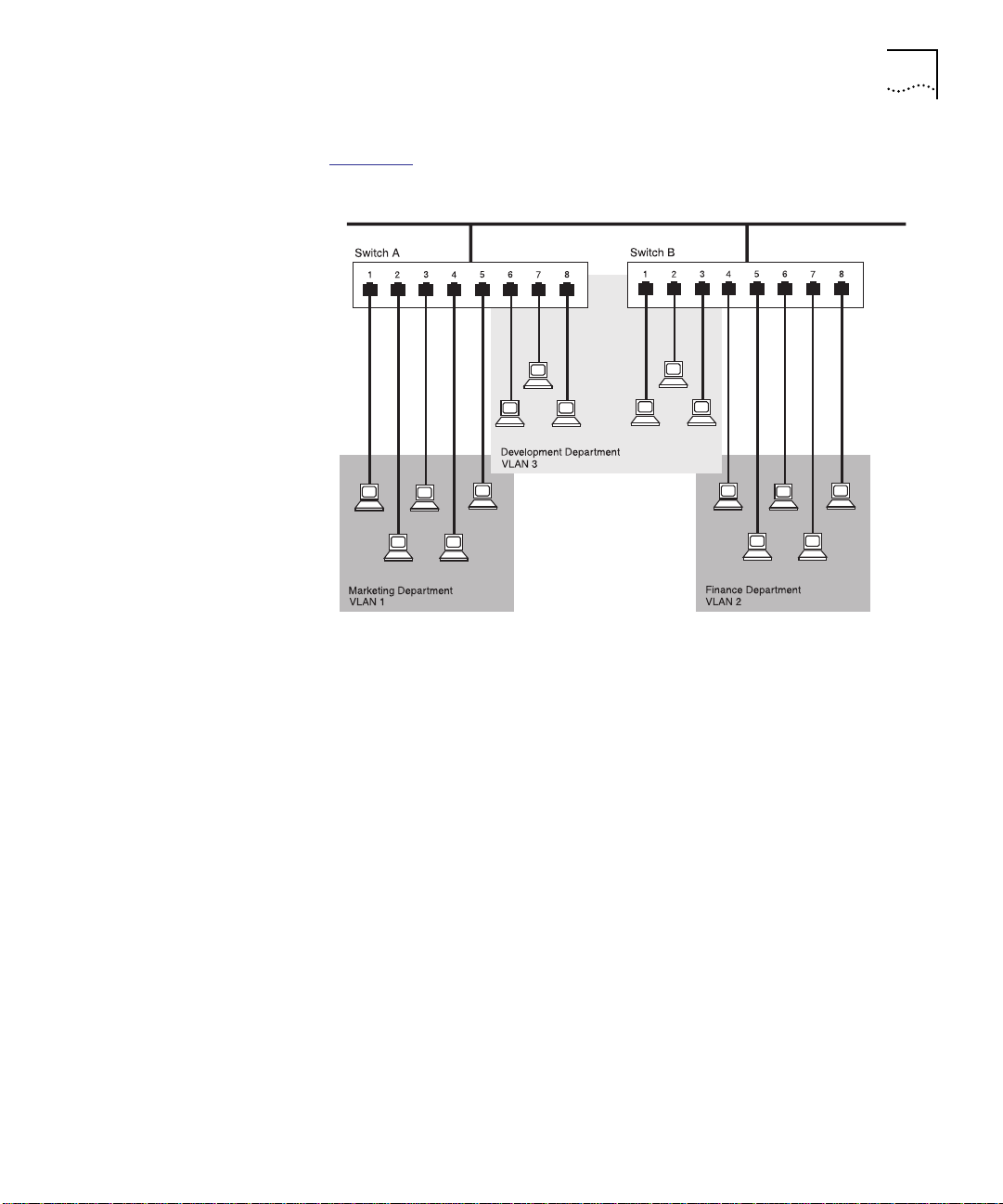
VLAN Overview 4-3
VLAN Example Figure 4-1 shows a network configured with port-based VLANs, in
which a VLAN consists of a set of FastModule ports.
Figure 4-1 Example VLAN
There is one VLAN for each of the three departments who access the
network. The membership of VLAN 1 is restricted to ports 1, 2, 3, 4
and 5 of Switch A; membership of VLAN 2 is restricted to ports 4, 5, 6,
7 and 8 of Switch B while VLAN 3 spans both Switches containing
ports 6, 7, 8 of Switch A and 1, 2, 3 of Switch B.
In this simplified example, each of these VLANs is a broadcast domain.
A broadcast domain consists of physical LAN segments that are not
constrained by their physical location.
Specific configurations using the FastModules are shown later in this
chapter.
Page 96

4-4 CHAPTER 4: ADVANCED CONFIGURATION
Using VLANs With CoreBuilder 5000 FastModules
Understanding the
Default VLAN
Connecting VLANs
to a Router
CoreBuilder 5000 FastModules support port-based VLANs, where a
VLAN consists of a set of switch ports. Each switch port, other than VLT
ports, can belong to only one VLAN at any one time, regardless of the
device to which it is attached. Each FastModule can support up to
16 VLANs.
In any network setup, VLAN 1 is the Default VLAN. The Default VLAN is
the only VLAN which allows access to the management agent of the
unit. On a new FastModule, all the ports belong to VLAN 1 by default.
If you want the devices attached to a port to belong to another VLAN,
you must use the VLAN Setup screen to place the port in that VLAN.
For more information about the VLAN Setup screen, refer to Setting Up
VLANs on page 4-11.
If the devices in a VLAN need to talk to devices in a different VLAN,
each VLAN requires a connection to a router. Communication between
VLANs can only take place if they are all connected to the router. A
VLAN not connected to a router is isolated.
In a 24-Port FastModule, VLANs are typically connected to routers using
outlet ports. Outlet ports have the following attributes:
■ Addresses received on outlet ports are not stored in the FastModule
Database.
Connecting Common
VLANs Between
FastModules
■ Frames with unknown addresses are forwarded to the outlet ports.
If you connect a 24-Port FastModule to a router using outlet ports, you
must specify one outlet port for each VLAN connected to the router.
In a 24-Port FastModule, VLANs are typically connected to other
FastModules, using outlet ports. Similar to the router connections, you
normally require one outlet port per VLAN. However, to make the
FastModule-to-FastModule connections more cost-effective,
FastModules allow you to specify that one outlet port forms part of a
Virtual LAN Trunk (VLT). A VLT is a connection which carries traffic for
multiple VLANs between Fastmodules and other switch units. If you
configure both ends of a FastModule-to-FastModule connection as
part of a VLT, you only need that one connection for all the VLANs.
VLTs can only be used for links between FastModules. You cannot use
VLTs for FastModule-to-router links.
Page 97

Using VLANs With CoreBuilder 5000 FastModules 4-5
If you specify that an outlet port on one VLAN is part of a VLT, that
outlet port becomes an outlet port for all the VLANs on the
FastModule, even if they had no outlet port before. If you then disable
the VLT function on that port, the port will become the outlet port for
the Default VLAN (VLAN 1) and all other VLANs lose their outlet ports.
Sharing VLT Bandwidth
Each VLAN is capable of using 100 percent of the bandwidth on a VLT.
For example, assume that VLAN 1 and VLAN 2 share a VLT. Heavy
traffic on VLAN 1 can occupy 100 percent of the bandwidth available
on the VLT. This means that traffic generated on VLAN 2 may be
delayed until VLAN 1 traffic decreases, making VLT bandwidth available
to VLAN 2.
Using AutoSelect VLAN Mode
By default, all non-backplane ports on the FastModule use Port VLAN
Mode. Each switch port is manually placed in the required VLAN. The
FastModule allows some ports to select another mode, AutoSelect
VLAN Mode. In this mode, ports are automatically placed in the
required VLAN by referring to a VLAN Server database in 3Com
Transcend Enterprise Manager Version v6.0 for Windows
.
The advantage of AutoSelect VLAN Mode is that after you set up the
VLAN Server database correctly, you can move endstations to other
ports or other FastModule units. The VLAN assignment of each
endstation is automatically configured.
AutoSelect VLAN Mode functions as follows:
1 When an endstation is connected to a FastModule or moves from one
port to another, the FastModule learns the MAC address of the
endstation.
2 If the relevant port uses AutoSelect VLAN Mode, the FastModule refers
to the VLAN Server database which contains a VLAN allocation for each
MAC address.
3 After obtaining the VLAN allocation for the MAC address, the
FastModule places the relevant port in that VLAN.
If you use AutoSelect VLAN Mode, note the following:
■ You must specify an IP address and community string for the VLAN Server.
■ You cannot use VLAN 15.
Page 98

4-6 CHAPTER 4: ADVANCED CONFIGURATION
■ If you configure a port as an outlet port or as part of a VLT, the port
cannot use AutoSelect VLAN Mode.
■ If you store a permanent address for the port in the Switch
Database, the port cannot use AutoSelect VLAN Mode.
■ Connect each switch port to a single endstation. To connect a port
to multiple endstations, specify that the port uses Port VLAN Mode.
For information about Setting Up VLANs Using AutoSelect VLAN Mode
refer to page 4-14.
For more information about the VLAN Server database, refer to the
documentation supplied with Transcend Enterprise Manager.
Using Non-Routable Protocols
If you are running non-routable protocols on your network (for
example, DEC LAT or NET BIOS), devices within one VLAN cannot
communicate with devices in a different VLAN.
Connecting Multiple Network Adapters to a FastModule
If you connect a server with multiple network adapters to a
FastModule, you must configure each adapter with a unique
MAC address.
,
Page 99

VLAN Configurations Example 1
Using VLANs With CoreBuilder 5000 FastModules 4-7
The example shown in Figure 4-2
illustrates a simple VLAN
configuration comprising a single 24-Port FastModule. The ports are
divided between two VLANs. VLAN 1 is able to talk to VLAN 2 due to
the outlet port connection between each VLAN and the router.
VLAN 1
24-Port
VLAN 2
Router
Figure 4-2 VLAN Configuration With a Single FastModule
FastModule
Inter-VLAN
connection
To set up the configuration shown in Figure 4-2:
1 Use the FMA screens to:
a Place ports 1 through 12 in VLAN 1.
b Place ports 13 through 24 in VLAN 2.
2 Connect a port in VLAN 1 to the router.
3 Use the FMA screens to specify that the VLAN 1 port connected to the
router is an outlet port.
4 Repeat steps 2 and 3 for VLAN 2.
Page 100

4-8 CHAPTER 4: ADVANCED CONFIGURATION
Example 2
The example shown in Figure 4-3
24-Port FastModules. VLAN 1 is able to talk to VLAN 2 due to the
outlet port connection between each VLAN and the router.
Ports within the same VLAN which span the two FastModules
communicate through a VLT on the Fast Ethernet backplane.
illustrates two VLANs spanning two
Virtual LAN Trunk (VLT)
on Fast Ethernet Backplane
VLAN 1
VLAN 2
Inter-VLAN
connection
Router
24-Port FastModules
Server 1
in VLAN 1
Server 2
in VLAN 2
Figure 4-3 VLAN Configuration With Two 24-Port FastModules
To set up the configuration shown in Figure 4-3:
1 Use the FMA screens to:
a Place ports 1 through 12 of both FastModules in VLAN 1.
b Place ports 13 through 24 of both FastModules in VLAN 2.
2 Connect the port 1 of the right 24-Port FastModule to Server 1.
3 Connect port 1 of the left 24-Port FastModule to Server 2.
4 Use the FMA screens to:
a Place port 1 of the right 24-Port FastModule in VLAN 2.
b Place port 1 of the left 24-Port FastModule in VLAN 1.
 Loading...