

Page 1

CoreBuilder™5000 Ethernet
®
Private Line Card
User Guide
http://www.3com.com/
Document Number 17-00439-3
Published May 1997
Page 2

3Com Corporation
5400 Bayfront Plaza
Santa Clara, California
95052-8145
Copyright © 3Com Corporation, 1997. All rights reserved. No part of this documentation may be
reproduced in any form or by any means, or used to make any derivative work (such as translation,
transformation, or adaptation) without permission from 3Com Corporation. Portions of this document are
reproduced in whole or part with permission from third parties.
3Com Corporation reserves the right to revise this documentation and to make changes in content from
time to time without obligation on the part of 3Com Corporation to provide notification of such revision or
change.
3Com Corporation provides this documentation without warranty of any kind, either implied or expressed,
including, but not limited to, the implied warranties of merchantability and fitness for a particular purpose.
3Com may make improvements or changes in the products or programs described in this documentation at
any time.
UNITED STATES GOVERNMENT LEGENDS:
If you are a United States government agency, then this documentation and the software described herein
are provided to you subject to the following restricted rights:
For units of the Department of Defense:
Restricted Rights Legend: Use, duplication, or disclosure by the Government is subject to restrictions as set
forth in subparagraph (c) (1) (ii) for Restricted Rights in Technical Data and Computer Software Clause at
48 C.F.R. 52.227-7013.
For civilian agencies:
Restricted Rights Legend: Use, reproduction, or disclosure is subject to restrictions set forth in subparagraph
(a) through (d) of the Commercial Computer Software – Restricted Rights Clause at 48 C.F.R. 52.227-19
and the limitations set forth in the 3Com Corporation standard commercial agreement for the software.
Unpublished rights reserved under the copyright laws of the United States.
If there is any software on removable media described in this documentation, it is furnished under a license
agreement included with the product as a separate document, in the hardcopy documentation, or on the
removable media in a directory file named LICENSE.TXT. If you are unable to locate a copy, please contact
3Com and a copy will be sent to you.
Federal Communications Commission Notice
This equipment was tested and found to comply with the limits for a Class A digital device, pursuant to
Part 15 of the FCC Rules. These limits are designed to provide reasonable protection against harmful
interference when the equipment is operated in a commercial environment. This equipment generates,
uses, and can radiate radio frequency energy and, if not installed and used in accordance with the
instruction manual, may cause harmful interference to radio communications. Operation of this equipment
in a residential area is likely to cause harmful interference, in which case you must correct the interference
at your own expense.
Canadian Emissions Requirements
This Class A digital apparatus meets all requirements of the Canadian Interference-Causing Equipment
Regulations.
Cet appareil numérique de la classe A respecte toutes les exigences du Règlement sur le matériel brouilleur
du Canada.
EMC Directive Compliance
This equipment was tested and conforms to the Council Directive 89/336/EEC for electromagnetic
compatibility. Conformity with this directive is based upon compliance with the following harmonized
standards:
EN 55022 – Limits and Methods of Measurement of Radio Interference
EN 50082-1 – Electromagnetic Compatibility Generic Immunity Standard: Residential, Commercial, and
Light Industry
Warning: This is a Class A product. In a domestic environment, this product may cause radio interference, in
which case you may be required to take adequate measures.
Compliance with this directive depends on the use of shielded cables.
Low Voltage Directive Compliance
This equipment was tested and conforms to the Council Directive 72/23/EEC for safety of electrical
equipment. Conformity with this directive is based upon compliance with the following harmonized
standard:
EN 60950 – Safety of Information Technology Equipment
ii
Page 3

VCCI Class 1 Compliance
This equipment is in the 1st Class category (information equipment to be used in commercial or industrial
areas) and conforms to the standards set by the Voluntary Control Council for Interference by Information
Technology Equipment aimed at preventing radio interference in commercial or industrial areas.
Consequently, when the equipment is used in a residential area or in an adjacent area, radio interference
may be caused to radio and TV receivers, and so on.
Read the instructions for correct handling.
Fiber Cable Classification Notice
Use this equipment only with fiber cable classified by Underwriters Laboratories as to fire and smoke
characteristics in accordance with Section 770-2(b) and Section 725-2(b) of the National Electrical Code.
UK General Approval Statement
The CoreBuilder 5000 Integrated System Hub and ONline System Concentrator are manufactured to the
International Safety Standard EN 60950 and are approved in the U.K. under the General Approval Number
NS/G/12345/J/100003 for indirect connection to the public telecommunication network.
Trademarks
Unless otherwise indicated, 3Com registered trademarks are registered in the United States and may or may
not be registered in other countries.
3Com, Boundary Routing, CardFacts, EtherLink, LANplex, LANsentry, LinkBuilder, NETBuilder, NETBuilder II,
NetFacts, Parallel Tasking, SmartAgent, TokenDisk, TokenLink, Transcend, TriChannel, and ViewBuilder are
registered trademarks of 3Com Corporation.
3TECH, CELLplex, CoreBuilder, EtherDisk, EtherLink II, FDDILink, MultiProbe, NetProbe, and ONline are
trademarks of 3Com Corporation.
3ComFacts is a service mark of 3Com Corporation.
The 3Com Multichannel Architecture Communications System is registered under U.S. Patent
Number 5,301,303.
AT&T is a registered trademark of American Telephone and Telegraph Company.
Banyan and VINES are registered trademarks of Banyan Systems Inc.
CompuServe is a registered trademark of CompuServe, Inc.
DEC, DECnet, DELNI, POLYCENTER, VAX, VT100, VT220, and the Digital logo are trademarks of Digital
Equipment Corporation.
Hayes is a registered trademark of Hayes Microcomputer Products.
OpenView is a registered trademark of Hewlett-Packard Company.
Intel is a registered trademark of Intel Corporation.
AIX, IBM, and NetView are registered trademarks of International Business Machines Corporation.
Microsoft, MS-DOS, Windows, Windows 95, and Windows NT are registered trademarks of
Microsoft Corporation.
V30 is a trademark of NEC Corporation.
NetWare and Novell are registered trademarks of Novell, Incorporated.
IPX is a trademark of Novell, Incorporated.
OSF and OSF/Motif are registered trademarks of Open Software Foundation, Inc.
ONC, OpenWindows, Solaris, Solstice, Sun, Sun Microsystems, SunNet Manager, and SunOS are trademarks
of Sun Microsystems, Inc.
iii
Page 4

SPARCstation is a trademark licensed exclusively to Sun Microsystems Inc.
OPEN LOOK is a registered trademark of Unix System Laboratories, Inc.
UNIX is a registered trademark of X/Open Company, Ltd. in the United States and other countries.
Other brand and product names may be registered trademarks or trademarks of their respective holders.
iv
Page 5

CONTENTS
HOW TO USE THIS GUIDE
Audience 1
Structure of This Guide 1
Document Conventions 2
Related Documents 3
3Com Documents 3
Reference Documents 4
1 INTRODUCTION
CoreBuilder 5000 Ethernet Private Line Card Overview 1-1
Private Line Card Architecture Overview 1-2
Jamming Packets 1-4
Eavesdropping Event Timing 1-4
Intrusion Event Timing 1-5
Security Feature Overview 1-6
Autolearning 1-7
Eavesdropping Protection 1-7
Intrusion Protection 1-7
Theory of Operation 1-7
Ethernet Packet Transmission 1-7
Ethernet Security Issues 1-8
Eavesdropping Protection 1-8
Intrusion Detection 1-10
Where to Go From Here 1-11
2 INSTALLING THE PRIVATE LINE CARD
Precautionary Procedures 2-1
Unpacking Procedure 2-1
Installing a CoreBuilder 5000 Ethernet Private Line Card 2-2
Where to Go From Here 2-3
Page 6

3 CONFIGURING THE PRIVATE LINE CARD
Security Configuration Overview 3-2
Setting the Module to a Network 3-2
Showing and Configuring Port Parameters 3-3
Showing Port Security 3-4
Configuring Port Autolearning 3-5
Configuring Port Jamming 3-5
Configuring Port Intruder Checking 3-6
Configuring Failsafe 3-6
Configuring Group Codes 3-7
Showing and Configuring Network Parameters 3-8
Showing Network Security 3-8
Configuring Network Autolearning 3-9
Configuring Eavesdrop Protection 3-10
Configuring Source Address Checking 3-10
Configuring Source Port Checking 3-11
Configuring Intruder Jamming 3-12
Configuring Intruder Reporting 3-12
Configuring Intruder Port Disabling 3-13
Enabling Security on the Network 3-13
Security Address Table Information 3-14
Setting a MAC Address Manually 3-15
Showing MAC Addresses 3-16
Saving the MAC Address Table 3-17
Reverting to the Previous MAC Address Table 3-18
Deleting MAC Addresses 3-18
Security Intruder Table Information 3-18
Showing the Intruder Table 3-19
Deleting the Intruder Table 3-19
Where to Go From Here 3-20
vi
Page 7

4 TROUBLESHOOTING INFORMATION
Troubleshooting Using the Module Status LED 4-1
Troubleshooting PLC Configuration Problems 4-2
Hardware Configuration Problems 4-2
Software Configuration Problems 4-3
Technical Assistance 4-5
Where to Go From Here 4-5
A SPECIFICATIONS
General Specifications A-1
Power Specifications A-1
Environmental Specifications A-2
Mechanical Specifications A-2
B CONFIGURATION EXAMPLES
Providing Eavesdrop Protection with Continuous Autolearn B-1
Providing Maximum Security B-3
Configuring Security for a Complex Network Setup B-7
C TECHNICAL SUPPORT
Online Technical Services C-1
World Wide Web Site C-2
3Com Bulletin Board Service C-2
Access by Analog Modem C-2
Access by Digital Modem C-2
3ComFacts Automated Fax Service C-3
3ComForum on CompuServe Online Service C-3
Support From Your Network Supplier C-4
Support From 3Com Corporation C-5
Returning Products for Repair C-6
Accessing the 3Com MIB C-6
Contacting 3Com Technical Publications C-7
vii
Page 8

INDEX
3COM CORPORATION LIMITED WARRANTY
viii
Page 9

FIGURES
1-1 PLC and Media Module Interaction 1-3
1-2 Eavesdropping Event Timing Processing Time 1-4
1-3 Jamming a Packet with Eavesdropping Enabled 1-5
1-4 Eavesdropping Event Timing Processing Time 1-6
1-5 Jamming a Packet with Eavesdropping Enabled 1-6
1-6 Transmitting Packets on an Ethernet Network 1-8
1-7 Transmitting Information on a Secure Network 1-9
1-8 Sample Security Address Table 1-10
1-9 Intruder Transmissions on a Secure Network 1-10
2-1 Installing a CoreBuilder 5000 Private Line Card 2-3
B-1 Less Restrictive Network Security Setup B-2
B-2 Using the PLC to Provide Maximum Network Security B-6
B-3 Complex Network Security Setup B-8
ix
Page 10

Page 11

TABLES
3-1 Configuration Overview 3-2
3-2 Port and Related Network Parameters 3-3
4-1 Troubleshooting Using the Module Status LED 4-1
4-2 Troubleshooting Software Conflicts 4-3
A-1 General Specifications A-1
A-2 Power Specifications A-1
A-3 Environmental Specifications A-2
A-4 Mechanical Specifications A-2
B-1 Configuring Parameters to Provide Minimum Security B-2
B-2 Configuring Parameters to Provide Maximum Security B-4
B-3 Security Considerations for a Complex Network Setup B-9
xi
Page 12

Page 13

HOW TO USE THIS GUIDE
This guide explains how to install and operate the 3Com
CoreBuilder 5000 Ethernet Private Line Card (referenced throughout this
guide as the private line card or PLC). It also includes information on
configuring this card using a CoreBuilder
Management Module.
Before installing or using the private line card, read Chapters 1, 2, and
3 of this guide for basic installation and operation instructions.
Audience This guide is intended for the following people at your site:
■ Network manager or administrator
■ Hardware installer
™
5000 Distributed
Structure of This Guide
This guide contains the following chapters:
Chapter 1, Introduction – Describes the functions and features of
the CoreBuilder 5000 Ethernet Private Line Card.
Chapter 2, Installing the Private Line Card – Provides detailed
information on unpacking and installing the private line card.
Chapter 3, Configuring the Private Line Card – Explains how to
configure network and port configuration parameters. In addition, this
chapter provides information on the security address table and intruder
table.
Chapter 4, Troubleshooting Information – Provides help in
isolating and correcting problems that may arise when installing or
operating this module.
Page 14

2 HOW TO USE THIS GUIDE
Appendix A, Specifications – Provides electrical, environmental, and
mechanical specifications for the private line card.
Appendix B, Configuration Examples – Provides detailed examples
on the configuration of your network using the security features
provided by the PLC.
Appendix C, Technical Support – Lists the various methods for
contacting the 3Com technical support organization and for accessing
other product support services.
Index
Document Conventions
The following document conventions are used in this manual:
Convention Indicates Example
Courier text User input In the Agent Information Form, enter
MIS in the New Contact field.
System output After pressing the Apply button, the
Bold command string Path names Before you begin, read the readme.txt
Text in angled
brackets Italic text in
braces
Capitalized text in
plain brackets
Italics Text emphasis,
User-substituted
identifiers
Keyboard entry
by the user
document titles
system displays the message
Transmi tting dat a.
file located in /usr/ snm/a gent s.
In the command above, substitute
<rem_name> with the name of the
remote machine.
Use the following command to show
port details:
SHOW PORT {
Type your password and press
[ENTER].
Ensure that you press the Apply
button after you add the new search
parameters.
slot
.all} VERBOSE
Page 15

Related Documents 3
Icon Notice Type Alerts you to...
Information note Important features or instructions
Caution Risk of personal safety, system damage, or loss
of data
Warning Risk of severe personal injury
Related Documents This section provides information on supporting documentation,
including:
■ 3Com Documents
■ Reference Documents
3Com Documents The following documents provide additional information on 3Com
products:
CoreBuilder 5000 Integrated System Hub Installation and Operation
Guide – Provides information on the installation, operation, and
configuration of the CoreBuilder 5000 Integrated System Hub. This
guide also describes the principal features of the CoreBuilder 5000
Fault-Tolerant Controller Module.
CoreBuilder 5000 Distributed Management Module User Guide –
Provides information on the CoreBuilder 5000 Distributed
Management Module’s operation, installation, and configuration. This
guide also describes the software commands associated with the
Distributed Management Module.
CoreBuilder 5000 Distributed Management Module Commands Guide –
Describes each management command by providing detailed
information on the command’s format, use, and description.
For a complete list of 3Com documents, contact your 3Com
representative.
Page 16

4 HOW TO USE THIS GUIDE
Reference Documents The following documents supply related background information:
Case, J., Fedor, M., Scoffstall, M., and J. Davin, The Simple Network
Management Protocol, RFC 1157, University of Tennessee at Knoxville,
Performance Systems International and the MIT Laboratory for
Computer Science, May 1990.
Rose, M., and K. McCloghrie, Structure and Identification of
Management Information for TCP/IP-based Internets, RFC 1155,
Performance Systems International and Hughes LAN Systems, May
1990.
Page 17

1
INTRODUCTION
This chapter provides introductory information on the 3Com®
CoreBuilder 5000 Ethernet Private Line Card (PLC), including:
■ CoreBuilder 5000 Ethernet Private Line Card Overview
■ Private Line Card Architecture Overview
■ Jamming Packets
■ Security Feature Overview
■ Theory of Operation
■ Where to Go From Here
CoreBuilder 5000
Ethernet Private
Line Card Overview
The CoreBuilder™ 5000 Ethernet Private Line Card is a daughtercard
that you can install on any CoreBuilder 5000 Ethernet Media Module or
CoreBuilder 5000 Distributed Management Module with Ethernet
Carrier (6106M-MGT). The PLC enables you to secure any network to
which the card is assigned. Once assigned to an Ethernet network, you
can configure the PLC to provide:
■ Intrusion protection for all CoreBuilder 5000 Ethernet ports
■ Eavesdropping protection for all CoreBuilder 5000 Ethernet ports
■ MAC address autolearning, including continuous self-management
of address tables
■ Optional port disable when the PLC detects intruders
You must use DMM 2.00 software or above to manage and configure
the PLC.
Page 18

1-2 INTRODUCTION
Private Line Card Architecture Overview
To provide security for your network, the PLC and media module (or
DMM) must work together. To accomplish this, the PLC and the media
module need to communicate with each other using the:
■ Serial Identification (SID) Line
■ Ethernet Backplane Network
Serial Identification Line – The PLC uses the SID to send security
messages to the media module. Security messages instruct the media
module to either pass or jam a packet. In addition, the PLC uses the
SID to receive slot and port information for each packet that is
transmitted on the backplane.
Ethernet Backplane Network – The PLC uses the Ethernet backplane
network to listen for the destination address of each packet transmitted
on the backplane. The PLC looks up each source and destination
address to ensure it is valid. Once the PLC determines the validity of a
packet, it generates a security message and sends that message to the
media module using the SID.
The combination of these two communication paths enables the PLC
and the media module to effectively provide security for your network
(see Figure 1-1
).
The media module performs a pass or jam of a packet on a per-port
basis.
Page 19
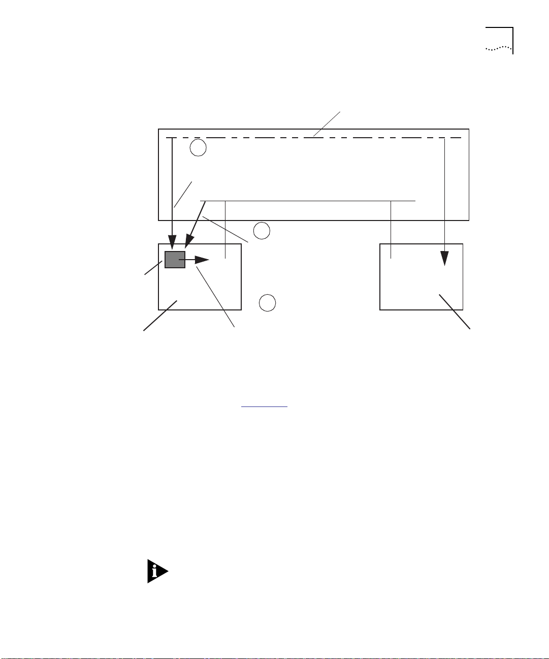
PLC
Media
module
Private Line Card Architecture Overview 1-3
Serial Identi fication Line
HUB
1
PLC receives the slot and port ident ific ation for
the packet from the media module.
Back plane segment
2
PLC receives the destination
address for the packet from the
media mo dule.
3
PLC generates a security message and sends it to all
media modules attached to the backplane segment.
The media modules then pass or jam the packet
based on the security message.
Media
module
Figure 1-1 PLC and Media Module Interaction
As shown in Figure 1-1, the PLC issues security messages on a per
packet basis to all repeater ports in the hub. Each port interprets the
message and either jams or passes the packet. Jamming packets not
only prevents eavesdropping, but also prevents the successful
transmission of an intruder's packet.
A jammed packet consists of alternating 1s and 0s in place of the
packet data. A jammed packet has the same length as the originally
transmitted packet. A station that receives a jammed packet will
disregard the packet because the cyclical redundancy check (CRC) field
of the packet is incorrect. You can enable or disable jamming on a
per-port basis.
Security processing is done as the packet passes through the system.
Consequently, the PLC adds no additional delay to packet transmissions.
Page 20
1-4 INTRODUCTION
Jamming Packets Before the PLC instructs a media module to jam a packet, it must first
look up the appropriate source or destination address and transmit the
security message to the media module. The time it takes to process
each request differs depending on whether the media module jams an
intruder packet or provides eavesdropping protection.
The remainder of this section describes packet jamming and packet
event timing, including:
■ Eavesdropping Event Timing
■ Intruder Event Timing
Eavesdropping
Event Timing
Before the PLC instructs the media module to jam a packet, it must first
determine if the port that receives the packet is the intended recipient.
Once the PLC receives the destination address of the packet, it
performs the following:
1 The PLC performs a lookup of the packet destination address and
creates a security message (processing time – 8 bit times).
2 The PLC transmits the security message to all media modules using the
Serial Identification (SID) Line (processing time – 16 bit times).
3 The media module processes the security message and performs a jam
if necessary (processing time – 8 bit times).
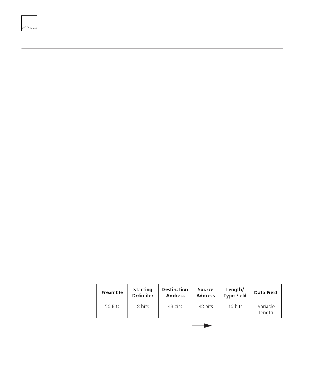
To complete the generation of the security message, the entire process
requires a total of 32 bit times. Because the PLC needs to look up the
destination address of the packet, the eavesdropping event timing
begins at the end of the destination address field as shown in
Figure 1-2
.
32 bit times (total processing time)
Figure 1-2 Eavesdropping Event Timing Processing Time
Page 21
Jamming Packets 1-5
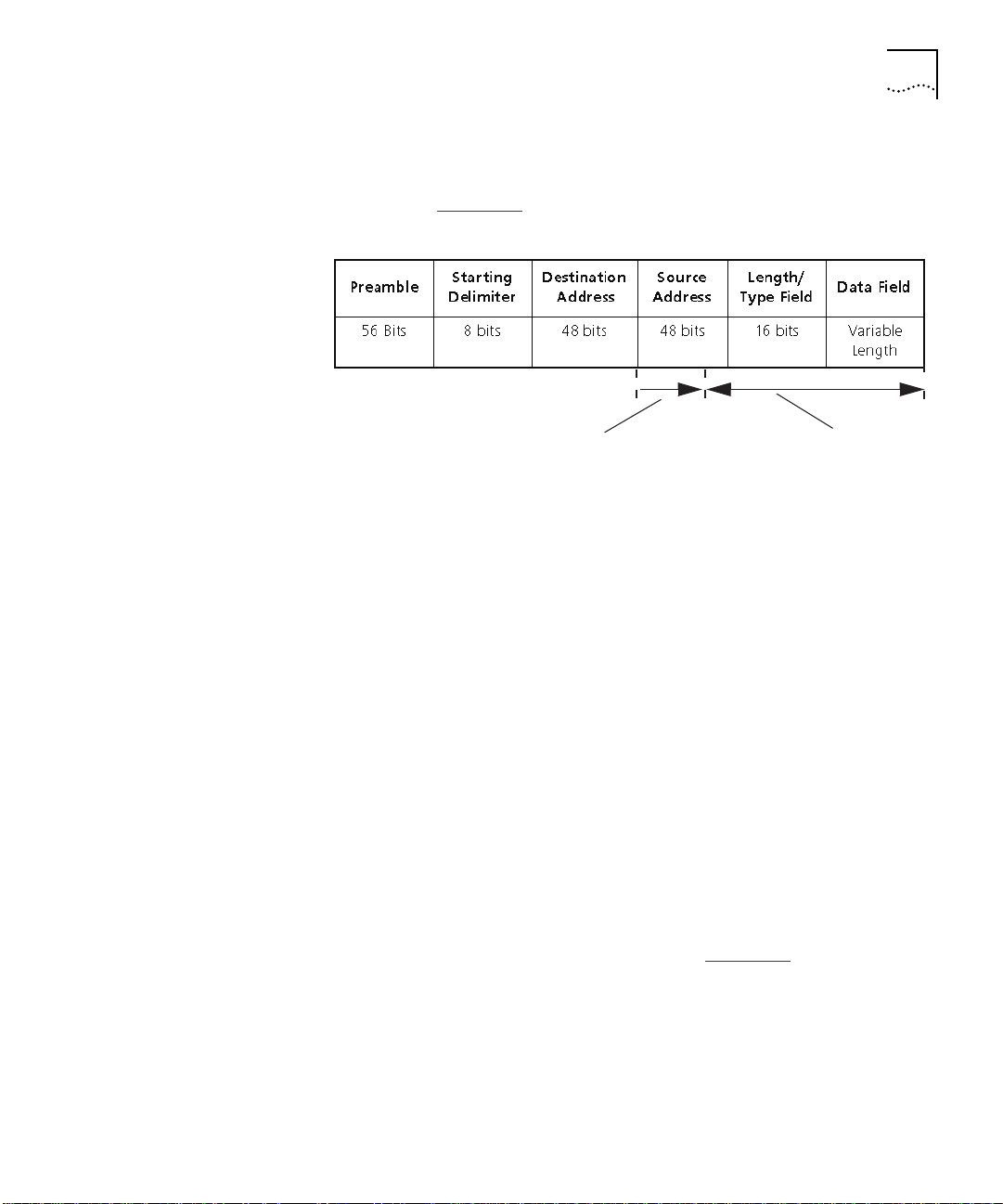
If the security message that the media module generates jams the
packet, the jam occurs after the first 32 bits of the source address field
as shown in Figure 1-3
.
Intrusion Event
Timing
32 bit times (total processing time)
Figure 1-3 Jamming a Packet with Eavesdropping Enabled
Data is jamm ed
Before the PLC instructs the media module to jam a packet, it must first
determine if the source address of the packet that is transmitted
belongs to a valid user.
Once the PLC receives the source address of the packet, it performs the
following:
1 The PLC performs a lookup of the packet source address and creates a
security message (processing time – 11 bit times).
2 The PLC transmits the security message to all media modules using the
Serial Identification (SID) Line (processing time – 16 bit times).
3 The media module processes the security message and performs a jam
if necessary (processing time – 8 bit times).
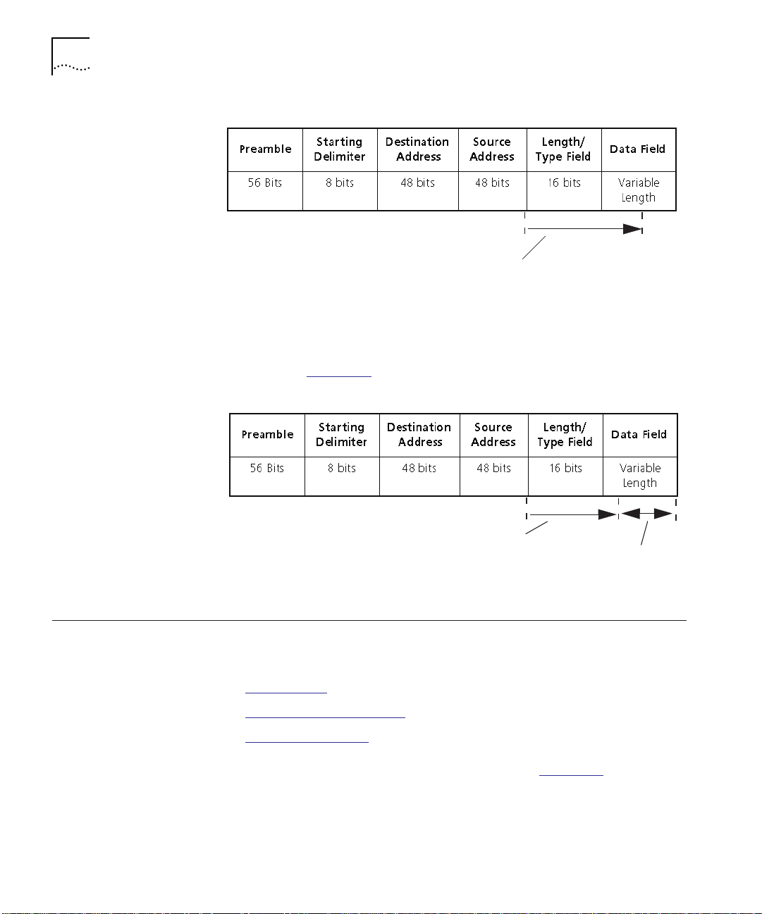
To complete the generation of the security message, the entire process
requires a total of 35 bit times. Because the PLC needs to look up the
source address of the packet, the intrusion event timing begins at the
end of the source address field as shown in Figure 1-4
.
Page 22
1-6 INTRODUCTION
35 bit times (total proc es si ng time )
Figure 1-4 Eavesdropping Event Timing Processing Time
If the security message that the media module generates jams the
packet, the jam occurs after the first 35 bits of the source address field
as shown in Figure 1-5
.
Security Feature Overview
35 bit times (total processing time)
Data is Jamm ed
Figure 1-5 Jamming a Packet with Eavesdropping Enabled
This section discusses some of the most commonly used network and
port security features that the PLC provides for your network, including:
■ Autolearning
■ Eavesdropping Protection
■ Intrusion Protection
For more information on these features, refer to Chapter 3,
Configuring the Private Line Card.
Page 23

Theory of Operation 1-7
Autolearning Network and port autolearning parameters enable the PLC to
automatically learn the MAC address for nodes on your network. Each
address is then stored in a security address table for future reference.
For example, if you set up a new security configuration on your
network, you can use the autolearning feature to quickly learn all valid
users on your network with per-port and network autolearning
enabled. Depending on your configuration, it is possible to have
continuous self-management of your address tables.
Eavesdropping
Protection
Eavesdropping protection prevents all nodes except the intended
recipient from receiving packets transmitted on the network. This
provides administrators with a private line Ethernet that ensures all
communication is successfully transmitted only to the intended recipient
of the packet. Packets transmitted to other nodes are jammed.
Intrusion Protection Intrusion protection prevents intruders from transmitting data to a port
with intrusion protection enabled on a secure network. Only valid
users (that is, users listed in the security address table) can successfully
transmit data on a secure network.
The PLC checks the cyclic redundancy check (CRC) for each packet to
ensure that partial packets are not treated as intruders.
Theory of
This section provides an overview of Ethernet, including:
Operation
■ Ethernet Packet Transmission
■ Ethernet Security Issues
Ethernet Packet
Transmission
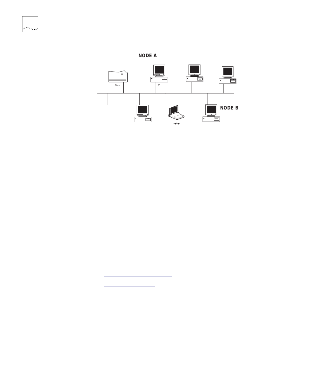
Each time a packet is transmitted on an Ethernet network it is
accessible by all nodes on that network. For example, in Figure 1-6
message transmitted from Node A to Node B is received by every node
on the network including the intended recipient. Each node examines
the transmitted packet and if the physical address of the node does not
match the destination address in the packet, the node discards the
packet.
, a
Page 24
1-8 INTRODUCTION
.
NODE A
PCPrinter
NODE B
Laptop
Figure 1-6 Transmitting Packets on an Ethernet Network
In a standard network, this type of transmission provides an adequate
method for exchanging data between nodes. In a secure environment,
however, this type of transmission is not acceptable.
Ethernet Security
Issues
To provide a secure method of data transfer on an Ethernet network,
you must ensure that you:
■ Prevent eavesdropping
■ Provide intruder detection
By providing both eavesdropping protection and intruder detection you
prevent unwanted listeners from monitoring the transmission of
Ethernet packets and you stop intruders from transmitting packets on
the network.
The remainder of this section describes:
■ Eavesdropping Protection
■ Intrusion Detection
Eavesdropping Protection
Eavesdropping prevents any user, including an intruder, from examining
the contents of a packet destined for another port.
The following example shows a typical use of the CoreBuilder 5000
Private Line Card to provide eavesdropping in a networked
environment.
Page 25
Theory of Operation 1-9
Preventing
Eavesdropping on a
Secure Network
VALID USER
Port 4.4
04-60-8c-8c-6 1-5a
VALID USER
Port 4.10
04-44-8c-7c-56-4b
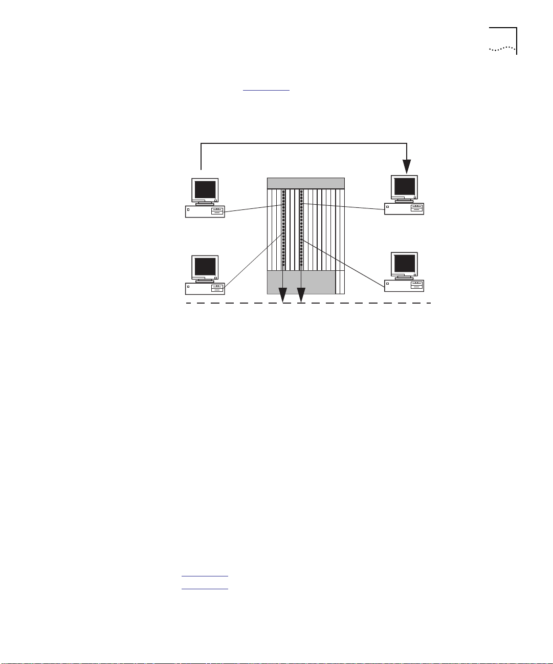
As shown in Figure 1-7, all nodes connect to Ethernet Network 2.
Message transmitted from User A to User C
A
B
Ethernet Network 2
C
D
VALID USER
Port 8.6
08-60-8c-7f-61-6f
VALID USER
Port 8.18
08-60-2c-7a-55-7d
Figure 1-7 Transmitting Information on a Secure Network
On the module in slot 4, a CoreBuilder 5000 Private Line Card is
attached and configured to secure Ethernet Network 2. To provide the
minimum amount of security, the network administrator has enabled
eavesdropping.
As a result, when User A transmits data to User C, the following
occurs:
■ User C successfully receives the MAC frame (packet)
■ The packet is jammed at all other ports so Users B and D cannot
examine the packet contents
Because the network administrator enabled eavesdropping, only the
destination address of User C is recognized by the PLC. Consequently,
all other transmitted packets, regardless of whether the intended
recipient is a valid user or intruder, are jammed at the port level.
Figure 1-8
Figure 1-7
represents the Security Address Table associated with
.
Page 26

1-10 INTRODUCTION
CB500 0> show se curity ad dress_tab le all [ENTER]
Entry Port Group_Code MAC_Address
----- ----- -- -------- -- --------- ------
1. 4.4 04-60-8 c-8c-61- 5a
2. 4.10 04-44-8 c-7c-56- 4b
3. 8.6 08-60-8 c-7f-61- 6f
4. 8.18 08-60-2 c-7a-55- 7d
Figure 1-8 Sample Security Address Table
Intrusion Detection
Intrusion detection prevents intruders from transmitting information to
other Ethernet ports. The information is transmitted on the backplane,
but it is jammed at all other ports on the secure network.
The following example shows a typical use of the CoreBuilder 5000
Private Line Card to provide intrusion protection in a networked
environment.
Preventing Intruder
Transmissions on a
Secure Network
VALID USER
Port 4.4
04-60-8c-8c-61-5a
INTRUDER
Port 4.10
04-44-8c-7c-5 6-4b
Intruder attempts to
transmit packets to
nodes on Ethernet
network 2.
In Figure 1-9, an intruder, attached to Port 10 of an Ethernet 24-Port
module, attempts to transmit data to Ethernet network 2.
A
X
X
X
B
Ethernet Network 2
Figure 1-9 Intruder Transmissions on a Secure Network
C
D
VALID USER
Port 8.6
08-60-8 c-7f-61-6f
VALID USER
Port 8.18
08-60-2c-7a-55-7d
Page 27

Where to Go From Here 1-11
Because the network administrator reconfigured the security protection
outlined in Figure 1-7
to enable intrusion detection as well as
eavesdropping, the following occurs:
■ User B (intruder) cannot successfully transmit data to any port.
■ Packets transmitted from the intruder are jammed at all other ports
Because the MAC address of User B is not found in the MAC address
table maintained for the media module in slot 4 of the hub, the PLC
classifies the user as an intruder. Consequently, all transmissions from
the intruder to a secure network are jammed at the port level.
Because the MAC address of the user attached to port 4.10
(04-44-8c-7c-56-4b) is not listed in the Security Address Table, it is also
possible to optionally report the intruder information to management
and disable port 4.10.
Where to Go From Here
Once you complete this chapter, proceed with Chapter 2, Installing the
Private Line Card.
Page 28

Page 29

INSTALLING THE PRIVATE LINE
2
Precautionary Procedures
CARD
This chapter describes how to unpack and install the CoreBuilder 5000
Private Line Card (PLC), including:
■ Precautionary Procedures
■ Unpacking Procedure
■ Installing a CoreBuilder 5000 Ethernet Private Line Card
■ Where to Go From Here
Electrostatic Discharge (ESD) can damage the static-sensitive devices on
circuit boards. To avoid this kind of damage, use the following
precautions when handling the card:
■ Do not remove the board from its antistatic shielding bag until you
are ready to install the PLC.
■ Use proper grounding techniques when inspecting and installing
the card. These techniques include using a foot strap and grounded
mat, or wearing a grounded static discharge wrist strap. An
alternate method is to touch a grounded rack or other source of
ground immediately before you handle the card.
Unpacking Procedure
When unpacking the PLC:
1 Verify that the PLC is the correct model by matching the model number
listed on the side of the shipping carton to the model number you
ordered. The PLC is Part Number 6100D-SEC.
Note that the product model number printed on the shipping box
differs from the model number on the product. The model number
on the shipping box contains the prefix ’3C9’.
Page 30

2-2 INSTALLING THE PRIVATE LINE CARD
2 Remove the card, in its antistatic bag, from the shipping carton.
3 Remove the card from the antistatic shielding bag and inspect it for
damage.
Always handle the card by the edges, ensuring that you do not
touch any of the components. If the card appears to be damaged,
return it to the anti-static shielding bag, repack it in the shipping
carton, and contact your local supplier.
Ensure that you keep the shipping carton and antistatic shielding bag in
which your card was shipped so that you can repackage the PLC for
storage or shipment.
Record the serial number of the PLC. The Hub Planning Charts, located
in the CoreBuilder 5000 Reference Binder, are provided for this
purpose.
Installing a
CoreBuilder 5000
Ethernet Private
Line Card
To install a PLC on a host module (CoreBuilder 5000 Ethernet Media
Module or on a Distributed Management Module with Ethernet
Carrier):
1 Properly ground yourself before you handle the PLC.
For example, attach a static wrist guard to yourself or touch a
grounded static mat before you handle the PLC.
2 Enter the SHOW POWER BUDGET command to ascertain if the hub has
enough power for the PLC. Refer to Power Specifications on page -1
for information on the power needed for each of the specified watt
ranges.
■ If the hub has enough power to accommodate the PLC, proceed
with step 3.
■ If the hub does not have enough power for the PLC, remove
another module or daughtercard until enough power is available.
Proceed with step 3.
Refer to the Distributed Management Module Commands Guide for
more detailed information on the SHOW POWER BUDGET command.
3 Match the PLC connector pins to the corresponding pins on the host
CoreBuilder 5000 Ethernet Media Module or CoreBuilder 5000 DMM.
Make sure that the standoffs align with the holes on the DMM or
media module.
Page 31

Where to Go From Here 2-3
4 Seat the PLC connector onto the media module or DMM-EC connector.
5 Secure the PLC to the media module or DMM-EC by screwing down
the two standoffs opposite the connector. Be careful not to
over-tighten.
Figure 2-1
Figure 2-1 Installing a CoreBuilder 5000 Private Line Card
shows how to install a private line card.
Connector
Standoffs
Screws
Where to Go From Here
Once you complete the installation of your private line card, proceed
with Chapter 3, Configuring the Private Line Card
.
Page 32

Page 33

CONFIGURING THE PRIVATE LINE
3
CARD
This chapter describes how to configure your CoreBuilder 5000
Ethernet Private Line Card to provide security for your network.
DMM Version v2.00 software or above is required to manage and
configure the private line card.
This chapter describes:
■ Security Configuration Overview
■ Setting the Module to a Network
■ Showing and Configuring Port Parameters
■ Showing and Configuring Network Parameters
■ Enabling Security on the Network
■ Security Address Table Information
■ Security Intruder Table Information
■ Where to Go From Here
When you initially add a PLC to the hub, the PLC will not become
operational until a DMM is present in the hub. After the DMM
configures the PLC, the PLC remains operational even if you later
remove the DMM.
Page 34

3-2 CONFIGURING THE PRIVATE LINE CARD
Security Configuration Overview
Setting the Module to a Network
Table 3-1 outlines the procedure for enabling and configuring security
for your network and media module ports. If you are familiar with
these procedures, use this table as a checklist. If you are not familiar
with these procedures, use the reference column in Ta b l e 3 -1
to refer
to the appropriate section.
Table 3-1 Configuration Overview
Step Procedure Reference
1. Set the module to a network. Refer to Setting the Module to a
Network on page 3-2
2. Configure security port
parameters
3. Configure security network
4. Enable security on the network Refer to Enabling Security on the
‡
It is recommended to configure your port security parameters prior to configuring your
parameters
network security parameters. This enables you to provide fully-configured port-level
security when you actually enable security on a network.
‡
Refer to Showing and Configuring
Port Parameters on page 3-3
Refer to Showing and Configuring
Network Parameters on page 3-8
Network on page 3-13
Before you can enable security on an Ethernet or isolated network,
you must set each module to an Ethernet or isolated network.
Use the following network management command to set your module
to a network:
SETMODULE{
slot.subslot
{ether ne t_ 1. .._8}
(isola te d_ 1. .._8}
} NETWO RK
For example, to set a CoreBuilder 5000 24-Port Module in slot 8 to
Ethernet network 2, enter the following at the DMM prompt:
CB5000> SET MODULE 8.1 NETWORK ETHERNET_2 [ENTER]
Page 35

Showing and Configuring Port Parameters 3-3
Showing and Configuring Port Parameters
The private line card enables you to provide security for modules on
both the port and the network level. Although it is possible to
configure your network parameters before you configure your port
parameters, it is not recommended.
Configuring port parameters before you configure network parameters
enables you to provide fully-configured port-level security when you
enable security on a network.
Once you configure port parameters, you must enable related network
parameters. Otherwise, port parameters will not function. Table 3-2
provides information on related port and network parameters. Refer to
this table as you configure your port parameters. The remainder of this
section describes each of these parameters.
The PLC does not prohibit you from assigning unsecure ports to a
secure network. The PLC does not, however, provide security for ports
that do not support security.
Table 3-2 Port and Related Network Parameters
Associated Network
Port Parameter
autolearning autolearning Enables autolearning on a port and
jamming eavesdrop_protection Enables or disables jamming of
intruder_checking source_address_checking Checks the address of packets sent
command heading
intruder_jamming
source_port_checking
Description
network level. Network autolearning
must be enabled for per-port
autolearning to function. This
parameter is disabled by default.
packets transmitted out the port to
the connected station. You must
enable this parameter to provide
eavesdropping and intrusion
protection. This parameter is
enabled by default.
from a port. You must have source
†
address checking enabled to
actually look up the source address
of a packet. To look up the source
port number, you need to have
source port checking enabled. This
parameter is disabled by default.
Page 36

3-4 CONFIGURING THE PRIVATE LINE CARD
Table 3-2 Port and Related Network Parameters (continued)
Port Parameter
‡
failsafe
group_code_A eavesdrop protection Group codes provide a method of
group_code_B
†
This parameter provides additional protection but is optional.
‡
Note that disabling security on the network or switching a port to an unsecured network
when failsafe is enabled causes the failsafe port parameter to jam all packets destined for
any port with per-port jamming enabled.
††
Group code 0, which means that the port is not assigned to a group, is the default for
each port. Group Code 1 to 254 are user defined. Group Code 255 is a reserved group
code. This code is designed to enable certain ports to route packets with an unknown
destination to a bridge or another hub.
Associated Network
command heading
Description
mode Packets are jammed at the port
level when jamming and failsafe
are enabled on the port and no
security message is sent from the
PLC to the media module. This
parameter is disabled by default.
assigning multiple ports to a single
MAC address. Group codes include
a range of 0 to 255.
††
Showing Port
Security
As you configure security for each of the networks in your hub, you
may wish to periodically display your port configuration. The SHOW
SECURITY PORT command enables you to view the configuration of
each secure port on your network.
To set the SHOW SECURITY PORT command, use the following
command syntax:
SHOW SECURITY PORT {
slot.port
{
slot
.all}
{all }
}
Page 37

Showing and Configuring Port Parameters 3-5
The following output is an example of the SHOW SECURITY PORT ALL
command (only the output for ports 1, 2, 3, and 4 are shown)
CB5000> show security port all [ENTER]
Security Port Table Display for Module 6124M-TPL6:
Port AutoLearn FailSafe Group_A Group_B Intruder_Check Jamming
---- --------- -------- ------- ------- -------------- -------
08.01 ENABLED DISABLED 0 0 ENABLED DISABLED
08.02 ENABLED DISABLED 0 0 ENABLED ENABLED
08.03 ENABLED DISABLED 0 0 ENABLED ENABLED
08.04 ENABLED DISABLED 0 0 ENABLED ENABLED
.
.
.
Configuring Port
Autolearning
Configuring Port
Jamming
Autolearning enables the PLC to scan a secure network and store the
MAC address and associated port of each node on the network in the
security address table. Once enabled, you can use this parameter, with
other port and network parameters, to secure the port.
To configure autolearning on a port, use the following command
syntax:
SET SECURITY PORT {
AUTOLE ARN {enabl e}
{disab le}
slot.port
{
slot.
all}
}
If autolearning is enabled on a per-port level, you must also enable
network autolearning and connect each port to a secure network.
Port jamming enables you to prevent eavesdropping, jam frames
sourced from an intruder on a secure network, and optionally jam all
packets for which there is no associated security message.
When you enable port jamming and the system transmits a packet on
the network, the PLC sends a security message to all media modules on
the secure network. This message instructs the media module to jam all
ports on the secure network except the port that is the intended
recipient of the transmitted packet. It also enables the media module to
jam a packet sourced from an intruder. This not only prevents intruders
and other valid users from examining the contents of a packet destined
for another port, but also prevents intruders from transmitting packets
on the network.
Page 38

3-6 CONFIGURING THE PRIVATE LINE CARD
To configure jamming on a port, use the following command syntax:
Configuring Port
Intruder Checking
SET SECURITY PORT {
JAMM ING {ena ble}
{disab le}
slot.port
{
slot
.all}
}
If jamming is enabled on a per-port level, you must also enable
network eavesdrop_protection and connect each port to a secure
network. If you also want to prevent each port from seeing intruder
transmissions, you must enable the intruder_jamming network
parameter.
This parameter is enabled by default. This prevents new users from
both eavesdropping and seeing packets sourced from an intruder on
another port.
When you enable per-port intruder checking the PLC checks each
packet’s source MAC address against an established list of valid MAC
addresses in the security address table. If the source address of the port
does not match an address in the security table, the packet is treated
as an intruder.
To configure intruder checking on a port, use the following command
syntax:
SET SECURITY PORT {
INTR UDER_ CH ECKI NG {e na ble}
{disab le}
slot.port
{
slot
.all}
}
You must have the source_address_checking network parameter
enabled to look up the source address of a transmitted packet. To look
up the source port number, you must have the source_port_checking
network parameter enabled. Both the source address and related
source port number must match a port number and MAC address in
the security address table or the packet is treated as an intruder.
Configuring Failsafe This port parameter instructs any media module connected to a secure
network to expect a security message transmission from the PLC for
each transmitted packet. This message provides information on whether
or not the module should jam a transmitted packet.
Page 39

Showing and Configuring Port Parameters 3-7
If, however, a security message for a packet is not transmitted to the
media module, and per-port jamming and failsafe are enabled, the
media module automatically jams all outgoing packets.
You must enable failsafe and per-port jamming for failsafe to function.
To configure failsafe, use the following command syntax:
Configuring Group
Codes
SET SECURITY PORT {
FAIL SAFE {ena ble}
{disab le}
slot.port}
{
slot
.all}
Do not enable failsafe on a port until that port is operational and the
appropriate security port and network parameters are set.
Once security is configured, do not disable security on a network that
has per-port failsafe enabled, or switch a secure port to an unsecured
network. Disabling security or switching the port to an unsecured
network causes the failsafe port parameter to jam all transmitted
packets destined for the port.
Group codes enable you to assign a single MAC address to multiple
ports on a secure network. This is an important feature when you use
two ports to form a redundant link to a node. You can also assign each
port to a maximum of two group codes.
If you assign multiple ports to a single group code, data sourced from
addresses also associated with the group code are transmitted to the
network.
To configure group codes on a port, use the following command
syntax:
SET SECURITY PORT {slot.port}
GROUP_ COD E_A {0...2 55}
GROUP_ COD E_B
Page 40

3-8 CONFIGURING THE PRIVATE LINE CARD
Note that group code 255 is a global group code. The global group
code is designed to enable certain ports to route packets with an
unknown destination. If, for example, one of the ports on your media
module is connected to another hub or to an external bridge, you must
configure that port using the global group code. This ensures that all
traffic destined for another hub is not jammed on the originating hub.
If you configure a port with jamming and assign the global group code
to that port, any packets that the system transmits on the originating
hub that are not destined for a node on a remote hub, are still jammed
at that port. Only packets with an unknown destination are sent to the
remote hub.
Group code 0 is the default and signifies that the port is not assigned
to a group code. Group code 1 to 254 are user defined group codes.
Showing and Configuring Network Parameters
Showing Network
Security
See Appendix B, Configuration Examples
that uses group codes.
Once you configure your security port parameters, you must configure
all related network parameters. Before you configure and enable
security network parameters you must first set the host module to an
Ethernet network (See Setting the Module to a Network
For more information on configuring network parameters, refer to the
following sections. For more information on related port parameters,
refer to Table 3-2
As you configure security for each of the networks in your hub, you
may wish to periodically display the security parameter configuration
for the network. The SHOW SECURITY NETWORK command enables
you to view the configuration of each security attribute on your
network.
on page 3-3.
for a sample configuration
on page 3-2.)
Page 41

Showing and Configuring Network Parameters 3-9
To set the SHOW SECURITY NETWORK command, use the following
command syntax:
SHOW SE CURITY NET WORK
{ether net_1..._ 8}
{isolated_1..._8} SLOT {
{all}
slot
The following output shows an example of the SHOW SECURITY
NETWORK ALL command (only the output for Ethernet_4 is shown):
CB5000 > show secu rity networ k etherne t_4 [ENTER]
ETHERN ET_4 Netwo rk Securi ty Configuration
------ --------- -------- --------- ----------- -------- --------- ------Securi ng Module: Slot 1 2.04 Vers ion a1.00.2
100D-SEC: CB5000 Ethernet Private Line
Card
Operat ional Mode ENABLED
Admini strative M ode ENABL ED
Autole arning: DISAB LED
Eavesd rop Protec tion: DIS ABLED
Intruder Detection: Intruder Actions:
Source Addr ess Checki ng: D ISABLED I ntruder J amming:DISABLED
Source Port Chec king: DIS ABLED Int ruder Reporting :ENABLED
Intruder Port Disabling:DISABLED
.
.
.
}
Configuring
Network
Autolearning
Network autolearning allows you to enable port autolearning on a
secure network. Once enabled, you can use this parameter, with other
port and network parameters, to secure ports connected to the secure
network.
Page 42

3-10 CONFIGURING THE PRIVATE LINE CARD
To configure autolearning on the network, use the following command
syntax:
SET SECURITY NETWORK
{ether net_1.. ._8}
AUTOLE ARNING {enabl e}
Configuring
Eavesdrop Protection
{iso lated_1.. ._8} SLOT {
{disab le}
slot
}
If network autolearning is enabled, you must also enable per-port
autolearning.
Any time you manually add an address to the Security Address Table,
the system removes previous port assignments for that address.
However, if you enable autolearning, the system does not modify the
Security Address Table entries if they are assigned to a group code.
Enabling eavesdrop protection on a secure network allows you to
prevent all ports with per-port jamming enabled from eavesdropping on
a secure network. This prevents intruders and other valid users from
examining the contents of a packet destined for another port.
To configure eavesdrop protection on the network, use the following
command syntax:
SET SECURITY NETWORK
{ether net _1.. ._ 8}
EAVE SDROP _P ROTE CT ION {ena ble}
{iso lated _1 ..._ 8} SL OT {
{disab le}
slot
}
Configuring Source
Address Checking
When you enable network eavesdrop and autolearn, the PLC passes
packets with unknown destinations to all ports.
When you enable source address checking, the source address of each
packet transmitted on a secure network is checked against an
established list of valid MAC addresses in the security address table. If
the source address of the port does not match an address in the
security table, the packet is treated as an intruder.
Page 43

Showing and Configuring Network Parameters 3-11
To configure source address protection on the network, use the
following command syntax:
SET SECURITY NETWORK
{ether net _1.. ._8}
SOUR CE_AD DRES S_ CHEC KING {ena ble}
Configuring Source
Port Checking
{iso lated _1.. ._ 8} SLOT {
{disab le}
slot
}
If you enable source address checking on your network, only ports with
intruder checking enabled are looked up in the security address table.
If you disable source address checking, the PLC automatically disables
source port checking.
When you enable source port checking, the source port number and
MAC address of each packet transmitted on a secure network is
checked against an established list of valid port numbers and MAC
addresses in the security address table. If the source port number and
MAC address of the packet does not match the port number and MAC
address in the security table, the packet is treated as an intruder.
To configure source port protection on the network, use the following
command syntax:
SET SECURITY NETWORK
{ether net _1.. ._ 8}
SOUR CE_PO RT _CHE CK ING {ena ble}
{iso lated _1 ..._ 8} SL OT {
{disab le}
slot
}
If you enable source port checking on your network, only ports with
intruder checking enabled are looked up in the security address table.
When you enable source port checking, the PLC automatically enables
source address checking.
Page 44

3-12 CONFIGURING THE PRIVATE LINE CARD
Configuring Intruder
Jamming
Configuring Intruder
Reporting
When the PLC detects an intruder packet on a secure network, the
intruder jamming network parameter enables the host module to
transmit a jam message to all ports on the network. This prevents all
end nodes attached to a port with per-port jamming enabled, from
receiving or examining the contents of the intruder packets.
To configure intruder jamming on the network, use the following
command syntax:
SET SECURITY NETWORK
{ether net _1.. ._ 8}
INTRUD ER_ JAMM IN G {enabl e}
{isola ted _1.. ._ 8} {d isab le}
If you enable intruder jamming on your network, you must also enable
either the source port checking or the source address checking network
parameter. If you do not enable either of these parameters, the host
module does not detect intruder packets.
To track intrusion attempts on a secure network you must enable the
intruder reporting network parameter. This parameter enables the PLC
to report intrusion attempts on a secure network. All reported intrusion
attempts are stored in the Intruder Table by the Distributed
Management Module (DMM).
The Security Intruder Table has a limit of 100 intrusion entries. Once
the table reaches the maximum limit, older entries expire automatically.
To configure intruder reporting on the network, use the following
command syntax:
SET SECURITY NETWORK
{ether net _1.. ._ 8}
INTRUD ER_ REPO RT ING {ena bl e}
{iso lated _1 ..._ 8} SL OT {
{disab le}
slot
}
Page 45

Enabling Security on the Network 3-13
To report intruders on a secure network, you must enable the source
address checking or the source port checking network parameter. If you
do not enable either of these parameters, the system does not detect
intruders.
When you disable intruder reporting, the PLC automatically disables
intruder port disabling.
Configuring Intruder
Port Disabling
Enabling Security on the Network
When you enable intruder port disabling, ports that receive intruder
packets are disabled automatically.
To configure intruder port disabling on the network, use the following
command syntax:
SET SECURITY NETWORK
{ether net _1.. ._ 8}
INTR UDER_ PO RT_D IS ABLI NG {enabl e}
{iso lated _1 ..._ 8} SL OT {
{disab le}
slot
}
If you enable intruder port disabling on your network, you must also
enable either the source port checking or the source address checking
network parameter. If you do not enable either of these parameters,
the host module will not detect intruder packets.
If you enable intruder port disabling, the PLC automatically enables
intruder reporting.
The security mode network parameter enables you to disable or enable
all network security functions. When this function is disabled, the PLC
does not send security messages to any media module connected to a
secure network. Consequently, if this parameter is disabled, none of the
network parameters will function.
Page 46

3-14 CONFIGURING THE PRIVATE LINE CARD
To enable security functions on a secure network, use the following
command syntax:
SET SECURITY NETWORK
{ether net _1.. ._ 8} MODE
{ena ble}
Security Address Table Information
{iso lated _1 ..._ 8} SL OT {
{disab le}
slot
}
Do not enable this network parameter until you have completed
configuring the remaining network parameters. This ensures that your
network security configuration is fully configured when you enable
security on the network.
The security address table contains the MAC address and associated
port for nodes on a secure network. Once set up, the PLC uses this
table to look up:
■ destination addresses (to provide eavesdrop protection)
■ source addresses (to provide intrusion protection)
In some instances, an attempt to access the security address table may
fail if the DMM is busy configuring the address table. This occurs when
the DMM or the PLC first boots. When this occurs, the DMM issues a
warning message. To successfully access the table, wait a short period
and retry.
You can define valid network users by:
■ Enabling autolearning on the secure network
■ Manually modifying the security address table
The following sections describe how to configure and examine the
security address table.
Although there is no limit on the number of addresses you can assign
to a port, the address table is limited to a total of 1000 entries. Once
the maximum limit is reached, new addresses are discarded.
Page 47

Security Address Table Information 3-15
Setting a MAC
Address Manually
In some instances, it is preferable to manually configure your security
address table. For example, if you work in an environment that
demands a high level of security, you may not want to enable
autolearning on a secure network.
In this type of environment, you should manually add users to the
security address table.
To add address information to your table manually, you can enter
either:
■ A MAC address and associated port
■ A MAC address and associated group code
The host module cannot autolearn group codes. You must set group
codes manually.
To add a MAC address and associated port or group code to your
security address table, use the following command syntax:
SET SECURITY ADDRESS_TABLE ADDRESS
{
address
{
slot.port
{1.. 254}
}PORT
}
{all} GROUP
If you assign multiple MAC addresses to a single group code, data
containing these addresses are transmitted to the network through
ports also associated with this group code.
When you assign a MAC address to a group code, that address is never
identified as an intruder when it is sourced from another port on the
network. In other words, network source port checking cannot check
the port for an address assigned to that group code.
Page 48

3-16 CONFIGURING THE PRIVATE LINE CARD
Showing MAC
Addresses
To show a MAC address or group of addresses you must use the
SHOW SECURITY ADDRESS TABLE command.
To show the address table information, use the following command
syntax:
SHOW SECURITY ADDRESS _T ABLE PORT
{
slot.port
{1...2 54}
}
{
slot
.all}
{all}
GROUP
{all}
ALL
The following output is an example of the SHOW SECURITY ADDRESS
TABLE ALL command.
CB5000> sho w security address_ table all [E NTER]
Entry P ort Group _Code MAC_A ddress
----- ----- -------- -- ------ --------- --
1. 25 08-00-8f-00-17-d0
2. 25 08-00-8f-00-17-d1
3. 8.15 08-00-8f-00-17-da
4. 8.16 08-00-8f-00-17-db
5. 8.17 08-00-8f-00-17-ce
6. 8.18 08-00-8f-00-17-cf
7. 8.19 08-00-8f-00-17-d3
8. 8.20 08-00-8f-00-17-d2
9. 8.21 08-00-8f-00-17-d9
10. 8 .22 08-00-8 f-00-17-d8
As shown in the previous output example, the first two MAC addresses
in the table are assigned to Group_Code 25. The remaining addresses
are paired with module port numbers.
Page 49

Security Address Table Information 3-17
Saving the MAC
Address Table
The SAVE SECURITY ADDRESS TABLE command enables you to save all
autolearned or manually configured MAC addresses and associated
port or group information.
To save the address table, use the following command syntax:
SAVE SE CURITY ADD RESS_TAB LE [ENTER]
When you save the Security Address Table, the information is saved in
non-volatile RAM on each PLC in the hub.
In addition, when you save the Security Address Table, the PLC also
saves the hub serial number with the table. Consequently, if you move
the PLC to a new hub, this prevents you from using addresses saved
from the original hub on the new hub.
The following output is an example of the SAVE SECURITY
ADDRESS_TABLE command for PLCs installed in slot 10 and 12 of a
CoreBuilder 5000 hub.
CB5000 > save secu rity addres s_table [ ENTER]
Security Ad dress Tabl e saved on security module 10.2
Security Ad dress Tabl e saved on security module 12.2
Security Ad dress Tabl e saved on security module 12.3
Use the SAVE SECURITY ADDRESS TABLE command each time you
update your security address table. This ensures that your current
configuration is saved and that the DMM table and the PLC Security
Address Table are in synch.
If the DMM table and the PLC Security Address Table are not in synch
and the PLC is rebooted, it may take several seconds for the PLC to
become operational. To avoid this problem, save the Security Address
Table to ensure that you synchronize both the DMM and Security
Address Table information.
Page 50

3-18 CONFIGURING THE PRIVATE LINE CARD
Reverting to the
Previous MAC
Address Table
Deleting MAC
Addresses
Security Intruder Table Information
The REVERT SECURITY ADDRESS TABLE command enables you to
discard your current address table configuration and revert to the
previously saved configuration.
To revert the address table, use the following command syntax:
REVERT SECURITY A DDRESS_TABLE [ENTER]
To delete a MAC address from the security table, use the following
command syntax:
SET SECURITY ADDRESS_TABLE ADDRESS {address}
DELE TE
{all}
The following output is an example of the SET SECURITY ADDRESS
TABLE DELETE command.
CB5000 > SET SECUR ITY ADDRESS_TAB LE ADDRESS ALL DELETE
[ENTER]
The security intruder table contains a detailed log on the last
100 intrusion attempts on each secured network. To log intrusion
attempts in the security intruder table you must:
■ Enable the intruder reporting network parameter
■ Enable per-port intruder checking
■ Enable either source address or source port checking
Once intrusion detection is properly configured, the PLC reports
intruders to the DMM which then stores the information in the security
intruder table.
Each table entry contains the:
■ MAC address and associated port or group code
■ date and time of the attempted intrusion
■ network on which the intrusion occurred
■ number of the intrusion attempts on the secured network
Page 51

Security Intruder Table Information 3-19
The following sections describe the intruder table.
The intruder table is not stored in non-volatile RAM (NVRAM).
Showing the
Intruder Table
CB5000 > show secu rity intrud er_table port [ENTER]
Security Intruder Table
Port Ma c Address Network At tempts Ti me Since I ntrusion
---- -- -------- - ------- -------- -- -------- --------- --
09.17 08-00-8f-00-17-d9 ETHERNET_1 328 0d 0h 31m 9s
09.18 08-00 -8f-00-17 -c2 ETHER NET_1 314 0d 0h 3 0m 29s.
.
.
.
CB5000 > show secu rity intruder_t able chron ological [ENTER]
Security Intruder Table
Port Ma c Address Network At tempts Ti me Since I ntrusion
---- -- -------- - ------- -------- -- -------- --------- --
07.01 fd-25 -ee-2d-ab -7e ETHER NET_5 1 0d 0 h 0m 4s
03.02 f b-ea-7c-5 3-f2-18 ETHERNE T_2 39 0d 1h 2m 22s
.
.
.
Use the SHOW SECURITY INTRUDER_TABLE command to display
information on recent intrusion attempts. The following output shows
two examples of the SHOW SECURITY INTRUDER_TABLE command.
Deleting the
Intruder Table
In some instances you may consider deleting your intruder table. For
example, if you receive a large amount of network intrusions due to
the failsafe parameter, you may opt to delete the intruder table once
you correct the source of the problem.
To delete your network intruder table, use the following command
syntax:
SET SEC URITY INTR UDER_TABLE DELETE [E NTER]
Page 52

3-20 CONFIGURING THE PRIVATE LINE CARD
Where to Go From Here
Once you complete this chapter, proceed to Chapter 4. Chapter 4
provides information on troubleshooting and technical assistance. If you
have problems with your private line card, you should refer to this
chapter before you contact 3Com Customer Support.
Page 53

4
TROUBLESHOOTING INFORMATION
This chapter provides detailed information on troubleshooting common
problems with your private line card. For more information specific
information on port and network parameters, refer to Chapter 3,
Configuring the Private Line Card
.
Troubleshooting Using the Module Status LED
In some situations, the module status LED on the host module blinks or
may not light. Table 4-1
probable solutions.
Table 4-1 Troubleshooting Using the Module Status LED
LED
State
OFF Hub power is off Check the controller module power
Blinks The securing module is faulty Try attaching the Private Line Card to a
Possible Problem Troubleshooting Solution
The hub does not have
enough available power for
the Private Line Card.
outlines both the possible reasons and some
LEDs.
different media module.
Use the SHOW POWER BUDGET
management command to ascertain
available power in the hub.
Page 54

4-2 TROUBLESHOOTING INFORMATION
Troubleshooting PLC Configuration Problems
Hardware
Configuration
Problems
Once you set up your PLC to provide security for your network, you
may encounter problems with your security configuration. This
remainder of this section describes:
■ Hardware Configuration Problems
■ Software Configuration Problems
If you experience problems with your PLC, before you contact
Customer Support, ensure that:
■ Your PLC is connected firmly to your media module or DMM-EC.
To confirm this, check to see if the PLC connector is seated firmly on
the securing module.
■ You have not overtightened the PLC connector screws while
attaching the PLC to the module.
■ Your securing module is functioning properly and that it is seated
firmly in the hub backplane connection.
■ You have enough available power in your hub to install and
operate the PLC (Use the SHOW POWER command).
If your hardware is set up properly and appears to function properly,
refer to Software Configuration Problems
in the next section for details
on possible configuration issues.
Page 55

Troubleshooting PLC Configuration Problems 4-3
Software
Configuration
Problems
If you confirm that your hardware configuration for the PLC is set up
and functioning properly and you still experience problems with your
PLC, you may have a software configuration conflict.
Table 4-2
provides detailed information on both possible software
configuration conflicts and probable solutions.
Table 4-2 Troubleshooting Software Conflicts
Problem Description Possible Reason Solution
Autolearning is enabled
but no address
information is stored in
the security address
table.
Intruders are not
detected by the
securing module.
Switching a secure port
to an unsecure network
causes the securing
module to jam all
packets destined for
that port.
PLC is reset by the
DMM.
Autolearning is enabled,
but new addresses are
not learned.
The Security Address
Table does not contain
MAC addresses that
were previously saved on
a PLC.
Network autolearning
is enabled, but per-port
autolearning is not
enabled.
Both source port
checking and source
address checking are
disabled.
Per-port intruder
checking is not enabled.
Intruder reporting is
disabled.
Failsafe is enabled on
the port.
DMM is having
problems
communicating with
the PLC.
Security Address Table is
full.
DMM does not load
addresses that were
saved by a PLC in a
different hub.
Enable per-port autolearning.
Enable one of these
network parameters.
Enable per-port intruder
checking.
Enable intruder reporting.
Disable failsafe on the port
or switch the port back to a
secured network.
Ensure that the PLC is
securely attached to the
media module. If the DMM
continually resets the PLC,
then replace it with a
different PLC.
Delete old or invalid
addresses.
Move the PLC back to the
original hub.
Use a new PLC.
Page 56

4-4 TROUBLESHOOTING INFORMATION
Table 4-2 Troubleshooting Software Conflicts (continued)
Problem Description Possible Reason Solution
The PLC is not
operational for several
seconds after a reboot.
Ports on a secure
network are still able to
see intruder
transmissions.
A backup link in a
redundant connection
to an end node does not
transmit packets when
the primary link fails.
The PLC does not
provide security for an
Ethernet segment
shared between two
hubs.
An Ethernet network
analyzer does not
function on the secure
network.
The show module all
command displays the
message Module Not
In Use
The PLC had a Security
Address Table that
differed from the DMM
table.
Per-port intruder
checking is not enabled.
The source address
checking network
parameter is not
enabled.
Per-port jamming is
disabled.
Network intruder
jamming is disabled.
Ports are assigned to
different group codes.
Ports do not have the
same security
configuration.
The second hub does
not have a PLC attached
to the Ethernet
segment. To secure a
network, one PLC is
required per segment,
per hub.
The port on which the
analyzer is connected
has per-port jamming
enabled.
The PLC was attached
to a network that was
already secured.
Use the SAVE SECURITY
ADDRESS TABLE command
each time you update your
security address table. This
ensures that your current
configuration is saved and
that the DMM table and the
PLC Security Address Table
are in synch.
Enable per-port intruder
checking.
Enable the source address
checking network parameter
on your network.
Enable per-port jamming on
ports that you want to jam
intruder packets.
Enable network intruder
jamming.
Assign a single group code
to both ports.
Configure both ports to
have the same security
configuration.
Add a PLC card to the
Ethernet segment in the
second hub.
Disable jamming on the port.
Set the PLC to an isolated
network and then set it to
an unsecured backplane
network.
Page 57

Technical Assistance 4-5
If you are still experiencing problems after carefully checking your
software configuration, contact 3Com Customer Support. Refer to
Appendix C
for information on contacting customer support.
Technical Assistance
Where to Go From Here
You can receive assistance for installing and troubleshooting the
CoreBuilder 5000 Ethernet Private Line Card by calling either your
3Com reseller or 3Com Technical Support. Be prepared to supply a
representative with the following information:
■ Description of the problem
■ Steps you have taken to try and correct the problem
■ Type and software version of the ONline network management
module being used
■ Version of software installed on your PLC
■ Status of the front panel LEDs
■ Configuration of your concentrator (you may find it helpful to refer
to the Slot Usage Chart in Appendix B of the ONline System
Concentrator Installation and Operation Guide for a record of this
information)
If you complete this chapter and are still unable to ascertain the cause
of a particular problem with your private line card, contact 3Com
Customer Support and provide them with the specific nature of your
problem. Refer to Appendix C
for information on contacting 3Com
Technical Support.
Page 58

Page 59

A
SPECIFICATIONS
This appendix lists the specifications for the CoreBuilder 5000 Ethernet
Private Line Card, including:
■ General Specifications
■ Power Specifications
■ Environmental Specifications
■ Mechanical Specifications
General Specifications
Power Specifications
Table A-1 provides the general operating specifications for the
CoreBuilder 5000 Ethernet Private Line Card.
Table A-1 General Specifications
Processors Memory
Motorola 68302 processor 1 MB of Flash EPROM
768 Kb of RAM
Table A-2 provides the power specifications for the CoreBuilder 5000
Ethernet Private Line Card.
Table A-2 Power Specifications
Power Requirements at
BTUs/Hr +5 V
4.25 W 14.5
Page 60

A-2 SPECIFICATIONS
Environmental Specifications
Mechanical Specifications
Table A-3 describes the required operating conditions for the
CoreBuilder 5000 Ethernet Private Line Card.
Table A-3 Environmental Specifications
Specification Value
Operating Temperature 32 to 122 °F (0 to 50 °C)
Operating Humidity Less than 95%, non-condensing
BTUs/hr 14.5
Table A-4 describes the mechanical specifications for the
CoreBuilder 5000 Ethernet Private Line Card.
Table A-4 Mechanical Specifications
Dimensions Weight
.68" W x 3.25" L x 4.5" H
(1.73 cm x 8.26 cm x 11.43 cm)
2.85 oz (80.1g)
Page 61

B
CONFIGURATION EXAMPLES
This appendix provides detailed examples on the configuration of your
network using the security features provided by the PLC, including:
■ Providing Eavesdrop Protection with Continuous Autolearn
■ Providing Maximum Security
■ Configuring Security for a Complex Network Setup
Providing
Eavesdrop
Protection with
Continuous
Autolearn
Providing Eavesdrop
Protection with
Continuous
Autolearn
When you plan your network security configuration, you may decide
that a less restrictive configuration is more appropriate for your
network. If you plan a less restrictive configuration, your primary
concern when you configure security is to provide:
■ Autolearning
■ Eavesdropping Protection
The following shows an example of a less restrictive network security
setup.
In Figure B-1, the network administrator connects User A1 to
Module A. Once connected, User A1 transmits data to User C1. To
provide a method for the host module to recognize the new user and
provide a secure method for transferring this data, the network
administrator needs to configure the PLC connected to backplane
segment 1 to:
■ Stop all learned users from eavesdropping on packet transmissions
■ Enable autolearning to provide continuous security address table
management
Page 62

B-2 CONFIGURATION EXAMPLES
PLC
Backpla ne
segment 1
Media module A
- 1.2
AB C - 3.4
slot and port ID
A1
Valid user
B1
C1
Valid
user
Figure B-1 Less Restrictive Network Security Setup
To configure the PLC to provide this protection, the administrator must
enable certain port and network security parameters. Table B-1
outlines the specific network and port parameters needed to configure
security in this manner. For more specific information on these
network and port parameters, refer to Chapter 3, Configuring the
Private Line Card.
.
Table B-1 Configuring Parameters to Provide Minimum Security
Enable the...
To...
Continuously manage
the security address
table
Prevent Network
Eavesdropping
Port Parameter Network Parameter
autolearning autolearning
jamming eavesdrop_protection
Page 63

Providing Maximum Security B-3
By implementing this configuration, the network administrator ensures
that:
■ All communication between valid users (A1 and C1) is private
■ User B1 is unable to eavesdrop on data transmissions
■ The MAC address of any new user the administrator adds is
automatically learned and added to the security address table.
In addition, once User A1 transmits data to port 1.2 on Module A, User
A1 is autolearned and the MAC address associated with the user is
stored in the security address table. When User C1 replies to User A1,
User C1 is similarly autolearned. This configuration provides automated
management of new users, while still providing eavesdropping
protection.
If you enable network eavesdropping and network autolearning, the
PLC passes packets with unknown destinations to all ports.
Providing Maximum Security
In some instances, you may decide that a more restrictive security
configuration is appropriate for your network. To configure the
maximum amount of security for your network, you should provide the
following protection:
■ Intrusion Detection (Enabled)
■ Eavesdropping Protection (Enabled)
■ Intruder Port Disable (Enabled)
■ Autolearning (Disabled)
■ Intruder Checking (Enabled)
■ Intruder Reporting (Enabled)
■ Failsafe (Enabled)
Once security is configured, do not disable security on a network that
has per-port failsafe enabled, or switch a secure port to an unsecured
network. Disabling security or switching the port to an unsecured
network causes the failsafe port parameter to jam all transmitted
packets destined for the port.
Page 64

B-4 CONFIGURATION EXAMPLES
The following example shows a maximum security configuration.
Setting Up a More
Restrictive Security
Configuration
The network administrator of a small financial consulting group decides
to increase the security on his company network.
The administrator’s goal in providing security is to:
■ Prevent eavesdropping on confidential data transmitted on the
network
■ Prevent intruders from transmitting data on the network
■ Tighten security by disallowing end users from moving the location
of their workstations to different ports on the network
■ Stringently control access to the network by manually editing and
updating the security address table
■ Automatically disable any port from which an intruder attempts to
transmit
■ Jam any packet that has no corresponding security message
■ Record the MAC address and slot and port ID of any attempted
intrusion
To configure the PLC to provide this protection, the network
administrator must enable the appropriate network and port
parameters. Table B-2
outlines each of these parameters.
Table B-2 Configuring Parameters to Provide Maximum Security
Enable the...
Associated Network
Item # To...
1 Prevent Intruder
Transmissions
2 Prevent Network
Eavesdropping
3 Disable any port that
transmits intruder
packets
4 Disallow end users from
moving workstations to
different ports
Port Parameter
intruder_checking source_address_checking
jamming intruder_jamming
jamming eavesdrop_protection
intruder_checking source_address_checking
intruder_checking source_port_disabling
command heading
or source_port checking
intruder_jamming
or source_port_checking
intruder_port_disabling
Page 65

Providing Maximum Security B-5
Table B-2 Configuring Parameters to Provide Maximum Security (continued)
Enable the...
Associated Network
Item # To...
5 Jam any packet with no
corresponding security
message
6 Record the MAC
address, slot, and port
ID of attempted
intrusions
7
8 Stringently control the
security address table
Port Parameter
failsafe mode
jamming
intruder_checking intruder_reporting
Disable the...
Port Parameter
autolearning autolearning
command heading
source_address_checking
or source_port checking
Associated Network
command heading
By configuring the parameters in Ta b l e B - 2 , the network administrator
provides the maximum amount of security for the network. For
example, using the configuration for the sample network shown in
Figure B-2
, has the following results:
■ User E1 can transmit data to User A1 privately. That is, Users B1 and
C1 cannot eavesdrop on this data transmission. (Refer to Item 2 in
Table B-2
■ User B1 cannot successfully move from port 3.3 to 2.11. (Refer to
Item 4 in Table B-2
■ User C1 cannot successfully transmit data to the network. If User C1
.)
.)
attempts to do so, packets sent to slot and port 5.9 are blocked at
all other nodes, the attempted transmission is recorded in the
intruder table, and the port is automatically disabled. (Refer to Item
Numbers 1, 6, and 3 respectively in Table B-2
■ Any attempt to disable security on Backplane Segment 1 or to
.)
switch a secured port to an unsecured backplane segment causes
the media module to immediately jam all outgoing packets to that
port or network. (Refer to Item Number 5 in Table B-2
■ New users added to the network must be manually added to the
.)
security address table to have access to the network. (Refer to Item
Number 7 in Table B-2
.)
Page 66

B-6 CONFIGURATION EXAMPLES
Hub
Media mo dule
PLC
Slot and port ID
A1
Workstation move not allowed
User B1 attempts to move
workstat ion from port 3.3 to
port 2.11
1.10
Figure B-2 Using the PLC to Provide Maximum Network Security
2.11
Backpla ne
segment 1
Intruder attempts to
B1
3.3
X
User E1 transmits data
to user A1
transmit da ta, but data is
blocked and port disabled
5.9
C1
4.25
E1
Page 67

Configuring Security for a Complex Network Setup B-7
Configuring Security for a Complex Network Setup
Configuring Security for
a Complex Network
In addition to the security considerations outlined in Table B-2, you may
need to provide additional security for a unique or complex network
setup. Some of these considerations may require that you:
■ provide eavesdropping protection between non-3Com or ONline
concentrators
■ configure a redundant link between two ports connected to a single
end node
■ provide a method to transfer data from one secured backplane
segment to another
■ enable an administrator to examine packet flow on a secured
network without disabling security on that network
The following provides a detailed example of these security
considerations.
To configure additional security for the network, the network
administrator examines the specific needs of the network setup. As
shown in Figure B-3
■ secure each separate backplane segment with a PLC
■ disable jamming on port 2.11 so that the Ethernet Network
, the administrator needs to:
Analyzer can examine packets sent to that port
■ provide eavesdropping protection between each non-3Com hub
(H1 and H2)
■ assign a global group code (255) to ports 3.3 and 5.9 so that
packets destined for another backplane segment automatically pass
through port 3.3 or 5.9 to the bridge connected to both backplane
segments
Page 68

B-8 CONFIGURATION EXAMPLES
Media module
PLC
Slot and port ID
A1
Hub
1.10
Ethernet
network
analyzer
2.11
3.3
H1
H2
Backup
link
4.22 4.23
4.24 4.25
B1
Backplane
segment 1
Backpl ane
segment 2
5.9
Primary
link
EXTERNAL BRIDGE
Figure B-3 Complex Network Security Setup
Page 69

Configuring Security for a Complex Network Setup B-9
To set up this configuration, the administrator must enable the
appropriate port and network parameters. Ta b le B - 3
outlines each of
these parameters.
Table B-3 Security Considerations for a Complex Network Setup
Configure the...
To...
Transfer data from one
backplane segment to
another
Configure a redundant
link between two
ports connected to a
single end node
Port Parameter Network Parameter
group_code_A or
group_code_B with a value
of 255
group_code_A or
group_code_B with the
eavesdrop_protection
(enabled)
autolearning (disabled)
eavesdrop_protection
(enabled)
same value (between 1 to
254) for both ports
connected to the node
Provide eavesdropping
protection between
non-3Com hubs
jamming (enabled for each
port that a non-3Com hub
is attached)
eavesdrop_protection
(enabled)
intruder_jamming
(enabled)
Use an Ethernet
Network Analyzer on a
secured network
jamming (disabled for the
port to which you wish to
connect an Ethernet
N/A
Network Analyzer)
By implementing this configuration, the administrator:
■ provides eavesdropping between non-3Com hubs (H1 and H2)
■ uses an Ethernet Network Analyzer on port 2.11
■ provides a redundant link to User B1
■ transfers data between backplane segment 1 and backplane
segment 2 through an external bridge using port 3.3 or 5.9
Page 70

Page 71

C
TECHNICAL SUPPORT
3Com provides access to technical support information through a
variety of services. This appendix describes these services.
Information contained in this appendix is correct at time of publication.
For the very latest, access 3Com Corporation’s World Wide Web site as
described below.
This appendix describes:
■ Online Technical Services
■ Support From Your Network Supplier
■ Support From 3Com Corporation
■ Returning Products for Repair
■ Accessing the 3Com MIB
Online Technical Services
■ Contacting 3Com Technical Publications
3Com offers worldwide product support 24 hours a day, 7 days a
week, through the following online systems:
■ World Wide Web Site
■ 3Com Bulletin Board Service
■ 3ComFacts Automated Fax Service
■ 3ComForum on CompuServe Online Service
Page 72

C-2 TECHNICAL SUPPORT
World Wide Web Site Access the latest networking information on 3Com Corporation’s World
Wide Web site by entering our URL into your Internet browser:
http ://ww w. 3Com .c om/
This service features news and information about 3Com products,
customer service and support, 3Com Corporation’s latest news releases,
NetAge Magazine, and more.
3Com Bulletin Board
Service
3ComBBS contains patches, software, and drivers for all 3Com
products, as well as technical articles. This service is available through
modem or ISDN 24 hours a day, 7 days a week.
Access by Analog Modem
To reach the service by modem, set your modem to 8 data bits,
no parity, and 1 stop bit. Call the telephone number nearest you:
Country Data Rate Telephone Number
Australia up to 14400 bps 61 2 9955 2073
Brazil up to 14400 bps 55 11 547 9666
France up to 14400 bps 33 1 6986 6954
Germany up to 28800 bps 4989 62732 188
Hong Kong up to 14400 bps 852 2537 5608
Italy (fee required) up to 14400 bps 39 2 27300680
Japan up to 14400 bps 81 3 3345 7266
Mexico up to 28800 bps 52 5 520 7853
P. R. of China up to 14400 bps 86 10 684 92351
Singapore up to 14400 bps 65 534 5693
Taiwan up to 14400 bps 886 2 377 5840
U.K. up to 28800 bps 44 1442 438278
U.S.A. up to 28800 bps 1 408 980 8204
Access by Digital Modem
ISDN users can call 3ComBBS using a digital modem for fast access up
to 56 Kbps. To access 3ComBBS using ISDN, use the following number:
408 654 2703
Page 73

Online Technical Services C-3
3ComFacts
Automated Fax
Service
3Com Corporation’s interactive fax service, 3ComFacts
SM
, provides data
sheets, technical articles, diagrams, and troubleshooting instructions on
3Com products 24 hours a day, 7 days a week.
Call 3ComFacts using your Touch-Tone telephone using one of these
international access numbers:
Country Telephone Number
Hong Kong 852 2537 5610
U.K. 44 1442 278279
U.S.A. 1 408 727 7021
Local access numbers are available within the following countries:
Telephone
Country
Australia 1 800 123853 Netherlands 06 0228049
Belgium 0800 71279 Norway 800 11062
Denmark 800 17319 Portugal 0505 442 607
Finland 98 001 4444 Russia (Moscow only) 956 0815
France 05 90 81 58 Spain 900 964 445
Germany 0130 81 80 63 Sweden 020 792954
Italy 1678 99085 U.K. 0800 626403
Number
Country
Telephone
Number
3ComForum on
CompuServe Online
Service
3ComForum is a CompuServe-based service containing patches,
software, drivers, and technical articles about 3Com products, as well
as a messaging section for peer support. To use 3ComForum, you
need a CompuServe
®
account.
To use 3ComForum:
1 Log on to CompuServe.
2 Ty pe
go threecom
3 Press Return to view the 3ComForum main menu.
Page 74

C-4 TECHNICAL SUPPORT
Support From Your Network Supplier
If additional assistance is required, contact your network supplier.
Several suppliers are authorized 3Com service partners who are
qualified to provide a variety of services, including network planning,
installation, hardware maintenance, application training, and support
services.
If you contact your network supplier for assistance, have the following
information ready:
■ Diagnostic error messages
■ A list of system hardware and software, including revision levels
■ Details about recent configuration changes, if applicable
If you are unable to contact your network supplier, refer to the
following section on how to contact 3Com.
Page 75

Support From 3Com Corporation C-5
Support From 3Com Corporation
If you are unable to receive support from your network supplier,
technical support contracts are available from 3Com.
Contact your local 3Com sales office to locate your authorized service
provider using one of the following numbers:
Regional Sales Office Telephone Number Regional Sales Office Telephone Number
3Com Corporation
U.S.A.
3Com ANZA
East
West
3Com Asia Limited
China
Hong Kong
India
Indonesia
Korea
Malaysia
Singapore
Taiwan
Thailand
3Com Benelux B.V.
Belgium
Netherlands
3Com Canada
Calgary
Montreal
Ottawa
Toronto
Vancouver
3Com France
3Com GmbH
Austria
Czech and Slovak Republics
Germany
Hungary
Poland
Switzerland
800 NET 3Com or
1 408 764 5000
61 2 9937 5000
61 3 9866 8022
86 10 68492 568 (Beijing)
86 21 6374 0220 Ext 6115
(Shanghai)
852 2501 1111
91 11 644 3974
62 21 523 9181
82 2 319 4711
60 3 732 7910
65 538 9368
886 2 377 5850
662 231 8151 4
32 725 0202
31 30 6029700
403 265 3266
514 683 3266
613 566 7055
416 498 3266
604 434 3266
33 1 69 86 68 00
43 1 5134323
42 2 21845 800
49 30 3498790 (Berlin)
49 89 627320 (Munich)
36 1 250 83 41
48 22 6451351
41 31 996 14 14
3Com Ireland
3Com Japan
3Com Latin America
Argentina
Brazil
Chile
Colombia
Mexico
Peru
Venezuela
3Com Mediterraneo
Italy
3Com Middle East
3Com Nordic AB
Denmark
Finland
Norway
Sweden
3Com Russia
3Com South Africa
3Com UK Limited
353 1 820 7077
81 3 3345 7251
54 1 312 3266
55 11 546 0869
56 2 633 9242
57 1 629 4110
52 5 520 7841
51 1 221 5399
58 2 953 8122
39 2 253011 (Milan)
39 6 5279941 (Rome)
971 4 349049
45 39 27 85 00
358 0 435 420 67
47 22 18 40 03
46 8 632 56 00
007 095 2580940
27 11 807 4397
44 131 2478558 (Edinburgh)
44 161 8737717 (Manchester)
44 1628 897000 (Marlow)
Page 76

C-6 TECHNICAL SUPPORT
Returning Products for Repair
Accessing the
3Com MIB
Before you send a product directly to 3Com for repair, you must first
obtain a Return Materials Authorization (RMA) number. Products sent
to 3Com without RMA numbers are returned to the sender unopened,
at the sender’s expense.
To obtain an RMA number, call or fax:
Country Telephone Number Fax Number
U.S.A. and Canada 1 800 876 3266, option 2 408 764 7120
Latin America 1 408 326 7801 408 764 7120
Europe, South Africa and
Middle East
Outside Europe, U.S.A.,
and Canada
44 1442 438125 44 1442 435822
1 408 326 7804 1 408 764 7120
The 3Com Management Information Base (MIB) describes commands
that enable you to manage 3Com SNMP-based products. The MIB is
available over the Internet on an anonymous FTP server. Updates to
these MIBs are released as new 3Com products are introduced.
To access Internet versions:
1 FTP to
ftp.3com.com (151.104.9.65).
2 Enter the login name anonymous .
3 Enter your full Internet e-mail address as the password
(for example,
4 Change to the /pub/mibs directory using the command
jdoe@company.com).
cd/pub/mibs.
5 Read the readisd.txt file to determine the MIB or MIBs you need to
manage your 3Com products.
6 To view the 3Com MIB, OID, or schema entries, enter the
■ To pause the display, press Ctrl+S.
■ To continue the display, press Ctrl+Q.
ls command.
7 Copy the MIB, OID, or schema files to your current directory using the
appropriate command (for example,
8 Exit the FTP session using the
quit command.
get isd.mib).
Page 77

Contacting 3Com Technical Publications C-7
Contacting 3Com Technical Publications
02/06/97
If you have comments or questions on 3Com Technical Publications
documents, contact the Technical Publications group by fax at
(508) 229-1551.
Page 78

Page 79

INDEX
Numerics
3Com Bulletin Board Service (3ComBBS), C-2
3Com sales offices, C-5
3Com URL, C-2
3ComFacts, C-3
3ComForum, C-3
A
Audience of Manual, 1
Autolearning, 1-7
Autolearning Port Parameter, 3-5
B
Bridge Data Transfer, B-9
bulletin board service, C-2
C
Communication Paths, 1-2
CompuServe, C-3
Configuration Overview, 3-2
Configuring Eavesdropping Protection, B-2
Configuring Network Parameters, 3-8 to 3-13
Configuring Port Parameters, 3-3
E
Eavesdropping Protection, 1-7, 1-8
Electrostatic Discharge, 2-1
Ethernet Backplane Network, 1-2
Ethernet Packet Transmission, 1-7
Ethernet Security, 1-8
Ethernet Sniffer, B-9
G
General Specifications, A-1
Global Group Code, B-7
Group Code Port Parameter, 3-7
I
Installing The PLC, 2-2
Intruder Checking, B-5
Intruder Checking Port Parameter, 3-6
Intrusion Attempts, 1-7
Intrusion Detection, 1-10
Intrusion Protection, 1-7
J
Jamming Port Parameter, 3-5
M
MAC Address Autolearning, 1-7
Maximum Security Configuration, B-3
MIBs
3Com
Minimum Security Configuration, B-1
, C-6
N
Network Parameter
Configuration
network supplier support, C-4
, 3-8 to 3-13
O
ONline Eavesdropping Protection, B-7
Online technical services, C-1
F
Failsafe, B-4
Failsafe Port Parameter, 3-6
fax service. See 3ComFacts
FCC notice
, ii
Page 80

2 INDEX
P
PLC
Architecture Overview
Autolearning, 1-7
Bridge Data Transfer, B-9
Communicating with the Media Module, 1-2
Communication Paths, 1-2
Configuration Overview, 3-2
Configuring Eavesdropping Protection, B-2
Eavesdropping, B-1
Eavesdropping Protection, 1-7, 1-8, B-7
Ethernet Backplane Network, 1-2
Ethernet Network Analyzer, B-9
Ethernet Sniffer, B-9
Failsafe, B-4
Installation, 2-2
Intruder Checking, B-5
Intrusion Attempts, 1-7
Intrusion Detection, 1-10
Intrusion Protection, 1-7
MAC Address Autolearning, 1-7
Maximum Security Configuration, B-3
Minimum Security, B-1
Redundant Links, B-9
Security Feature Overview, 1-6
Unpacking, 2-1
Port Parameter
Autolearning
Configuration, 3-3
Failsafe, 3-6
Group Codes, 3-7
Intruder Checking, 3-6
Jamming, 3-5
Overview, 3-3
Related Network Parameters, 3-3
power
specifications
Precautionary Procedures, 2-1
Electrostatic Discharge, 2-1
Preventing Eavesdropping, B-1
Private Line Card (see PLC)
Private Line Ethernet
, 3-5
, A-1
, 1-2
, 1-7
R
Redundant Links, B-9
returning products for repair, C-6
S
Security Address Table
Continuous Self Management
Security Feature Overview, 1-6
Serial Line Identification Line, 1-2
Simple Network Management Protocol (SNMP)
commands
SNMP. See Simple Network Management Protocol
Specifications
General
specifications
power
, C-6
, A-1
, A-1
, 1-7
T
Technical Assistance, 4-5
Technical Support, 4-5
technical support, C-1
3Com URL, C-2
bulletin board service, C-2
fax service, C-3
network suppliers, C-4
product repair, C-6
using CompuServe, C-3
Troubleshooting
Technical Assistance
, 4-5
U
Unpacking The PLC, 2-1
URL, C-2
W
World Wide Web, C-2
WWW, C-2
Page 81

3Com Corporation LIMITED WARRANTY
For purposes of this warranty, the CoreBuilder 5000 Ethernet Private Line Card is considered an Internetworking product.
HARDWARE 3Com warrants its hardware products to be free from defects in workmanship and materials, under
SOFTWARE 3Com warrants that the software programs licensed from it will perform in substantial conformance to the
normal use and service, for the following lengths of time from the date of purchase from 3Com or its
Authorized Reseller:
Internetworking products 1 year
Network adapters Lifetime
Ethernet stackable hubs and Unmanaged Ethernet fixed port repeaters Lifetime*
*Power supply and fans in the stackable hubs and unmanaged repeaters 1 year
Other hardware products 1 year
Spare parts and spares kits 90 days
If a product does not operate as warranted above during the applicable warranty period, 3Com shall, at
its option and expense, repair the defective product or part, deliver to Customer an equivalent product or
part to replace the defective item, or refund to Customer the purchase price paid for the defective
product. All products that are replaced will become the property of 3Com. Replacement products may be
new or reconditioned. Any replaced or repaired product or part has a 90-day warranty or the remainder of
the initial warranty period, whichever is longer.
3Com shall not be responsible for any software, firmware, information, or memory data of Customer
contained in, stored on, or integrated with any products returned to 3Com for repair, whether under
warranty or not.
program specifications therefor for a period of 90 days from the date of purchase from 3Com or its
Authorized Reseller. 3Com warrants the media containing software against failure during the warranty
period. No updates are provided. 3Com’s sole obligation with respect to this express warranty shall be (at
3Com’s discretion) to refund the purchase price paid by Customer for any defective software products, or
to replace any defective media with software which substantially conforms to 3Com’s applicable published
specifications. Customer assumes responsibility for the selection of the appropriate applications program
and associated reference materials. 3Com makes no warranty or representation that its software products
will work in combination with any hardware or applications software products provided by third parties,
that the operation of the software products will be uninterrupted or error free, or that all defects in the
software products will be corrected. For any third-party products listed in the 3Com software product
documentation or specifications as being compatible, 3Com will make reasonable efforts to provide
compatibility, except where the noncompatibility is caused by a “bug” or defect in the third party’s
product.
(1 year if not registered)
STANDARD WARRANTY
S
ERVICE
WARRANTIES EXCLUSIVE IF A 3COM PRODUCT DOES NOT OPERATE AS WARRANTED ABOVE, CUSTOMER’S SOLE REMEDY FOR
Standard warranty service for hardware products may be obtained by delivering the defective product,
accompanied by a copy of the dated proof of purchase, to 3Com’s Corporate Service Center or to an
Authorized 3Com Service Center during the applicable warranty period. Standard warranty service for
software products may be obtained by telephoning 3Com’s Corporate Service Center or an Authorized
3Com Service Center, within the warranty period. Products returned to 3Com’s Corporate Service Center
must be pre-authorized by 3Com with a Return Material Authorization (RMA) number marked on the
outside of the package, and sent prepaid, insured, and packaged appropriately for safe shipment. The
repaired or replaced item will be shipped to Customer, at 3Com’s expense, not later than 30 days after
receipt of the defective product by 3Com.
BREACH OF THAT WARRANTY SHALL BE REPAIR, REPLACEMENT, OR REFUND OF THE PURCHASE PRICE
PAID, AT 3COM’S OPTION. TO THE FULL EXTENT ALLOWED BY LAW, THE FOREGOING WARRANTIES AND
REMEDIES ARE EXCLUSIVE AND ARE IN LIEU OF ALL OTHER WARRANTIES, TERMS, OR CONDITIONS,
EXPRESS OR IMPLIED, EITHER IN FACT OR BY OPERATION OF LAW, STATUTORY OR OTHERWISE,
INCLUDING WARRANTIES, TERMS, OR CONDITIONS OF MERCHANTABILITY, FITNESS FOR A PARTICULAR
PURPOSE, AND SATISFACTORY QUALITY. 3COM NEITHER ASSUMES NOR AUTHORIZES ANY OTHER
PERSON TO ASSUME FOR IT ANY OTHER LIABILITY IN CONNECTION WITH THE SALE, INSTALLATION,
MAINTENANCE, OR USE OF ITS PRODUCTS.
Page 82

3COM SHALL NOT BE LIABLE UNDER THIS WARRANTY IF ITS TESTING AND EXAMINATION DISCLOSE
THAT THE ALLEGED DEFECT IN THE PRODUCT DOES NOT EXIST OR WAS CAUSED BY CUSTOMER’S OR
ANY THIRD PERSON’S MISUSE, NEGLECT, IMPROPER INSTALLATION OR TESTING, UNAUTHORIZED
ATTEMPTS TO REPAIR OR MODIFY, OR ANY OTHER CAUSE BEYOND THE RANGE OF THE INTENDED USE,
OR BY ACCIDENT, FIRE, LIGHTNING, OR OTHER HAZARD.
LIMITATION OF LIABILITY TO THE FULL EXTENT ALLOWED BY LAW, 3COM ALSO EXCLUDES FOR ITSELF AND ITS SUPPLIERS ANY
LIABILITY, WHETHER BASED IN CONTRACT OR TORT (INCLUDING NEGLIGENCE), FOR INCIDENTAL,
CONSEQUENTIAL, INDIRECT, SPECIAL, OR PUNITIVE DAMAGES OF ANY KIND, OR FOR LOSS OF REVENUE
OR PROFITS, LOSS OF BUSINESS, LOSS OF INFORMATION OR DATA, OR OTHER FINANCIAL LOSS ARISING
OUT OF OR IN CONNECTION WITH THE SALE, INSTALLATION, MAINTENANCE, USE, PERFORMANCE,
FAILURE, OR INTERRUPTION OF ITS PRODUCTS, EVEN IF 3COM OR ITS AUTHORIZED RESELLER HAS BEEN
ADVISED OF THE POSSIBILITY OF SUCH DAMAGES, AND LIMITS ITS LIABILITY TO REPAIR, REPLACEMENT,
OR REFUND OF THE PURCHASE PRICE PAID, AT 3COM’S OPTION. THIS DISCLAIMER OF LIABILITY FOR
DAMAGES WILL NOT BE AFFECTED IF ANY REMEDY PROVIDED HEREIN SHALL FAIL OF ITS ESSENTIAL
PURPOSE.
Some countries, states, or provinces do not allow the exclusion or limitation of implied warranties or the
limitation of incidental or consequential damages for certain products supplied to consumers, so the above
limitations and exclusions may be limited in their application to you. This warranty gives you specific legal
rights which may vary depending on local law.
GOVERNING LAW This Limited Warranty shall be governed by the laws of the state of California.
3Com Corporation, 5400 Bayfront Plaza, Santa Clara, CA 95052-8145 (408) 764-5000
10/20/96
 Loading...