

Page 1
CoreBuilder™5000 Integrated
®
System Hub Installation and
Operation Guide
http://www.3com.com/
Part No. 17-00362-8
Published May 1997
Page 2

3Com Corporation
5400 Bayfront Plaza
Santa Clara, California
95052-8145
Copyright ©3Com Corporation, 1997. All rights reserved. No part of this documentation may be
reproduced in any form or by any means or used to make any derivative work (such as translation,
transformation, or adaptation) without permission from 3Com Corporation.
3Com Corporation reserves the right to revise this documentation and to make changes in content from
time to time without obligation on the part of 3Com Corporation to provide notification of such revision
or change.
3Com Corporation provides this documentation without warranty of any kind, either implied or
expressed, including, but not limited to, the implied warranties of merchantability and fitness for a
particular purpose. 3Com may make improvements or changes in the products or the programs described
in this documentation at any time.
UNITED STATES GOVERNMENT LEGENDS:
If you are a United States government agency, then this documentation and the software described
herein are provided to you subject to the following restricted rights:
For units of the Department of Defense:
Restricted Rights Legend: Use, duplication, or disclosure by the Government is subject to restrictions as
set forth in subparagraph (c) (1) (ii) for Restricted Rights in Technical Data and Computer Software Clause
at 48 C.F.R. 52.227-7013.
For civilian agencies:
Restricted Rights Legend: Use, reproduction, or disclosure is subject to restrictions set forth in
subparagraph (a) through (d) of the Commercial Computer Software – Restricted Rights Clause at
48 C.F.R. 52.227-19 and the limitations set forth in 3Com Corporation’s standard commercial agreement
for the software. Unpublished rights reserved under the copyright laws of the United States.
If there is any software on removable media described in this documentation, it is furnished under a
license agreement included with the product as a separate document, in the hard copy documentation,
or on the removable media in a directory file named LICENSE.TXT. If you are unable to locate a copy,
contact 3Com and a copy will be sent to you.
Federal Communications Commission Notice
This equipment was tested and found to comply with the limits for a Class A digital device, pursuant to
Part 15 of the FCC Rules. These limits are designed to provide reasonable protection against harmful
interference when the equipment is operated in a commercial environment. This equipment generates,
uses, and can radiate radio frequency energy and, if not installed and used in accordance with the
instruction manual, may cause harmful interference to radio communications. Operation of this
equipment in a residential area is likely to cause harmful interference, in which case you must correct the
interference at your own expense.
Canadian Emissions Requirements
This Class A digital apparatus meets all requirements of the Canadian Interference-Causing Equipment
Regulations.
Cet appareil numérique de la classe A respecte toutes les exigences du Règlement sur le matériel
brouilleur du Canada.
EMC Directive Compliance
This equipment was tested and conforms to the Council Directive 89/336/EEC for electromagnetic
compatibility. Conformity with this directive is based upon compliance with the following harmonized
standards:
EN 55022 – Limits and Methods of Measurement of Radio Interference
EN 50082-1 – Electromagnetic Compatibility Generic Immunity Standard: Residential, Commercial, and
Light Industry
Warning: This is a Class A product. In a domestic environment, this product may cause radio interference,
in which case you may be required to take adequate measures.
Compliance with this directive depends on the use of shielded cables.
Low Voltage Directive Compliance
This equipment was tested and conforms to the Council Directive 72/23/EEC for safety of electrical
equipment. Conformity with this directive is based upon compliance with the following harmonized
standard:
EN 60950 – Safety of Information Technology Equipment
ii
Page 3

VCCI Class 1 Compliance
This equipment is in the 1st Class category (information equipment to be used in commercial or industrial
areas) and conforms to the standards set by the Voluntary Control Council for Interference by
Information Technology Equipment aimed at preventing radio interference in commercial or industrial
areas.
Consequently, when the equipment is used in a residential area or in an adjacent area, radio interference
may be caused to radio and TV receivers, and so on.
Read the instructions for correct handling.
Fiber Cable Classification Notice
Use this equipment only with fiber cable classified by Underwriters Laboratories as to fire and smoke
characteristics in accordance with Section 770-2(b) and Section 725-2(b) of the National Electrical Code.
UK General Approval Statement
The CoreBuilder 5000 Integrated System Hub and ONline System Concentrator are manufactured to the
International Safety Standard EN 60950 and are approved in the U.K. under the General Approval
Number NS/G/12345/J/100003 for indirect connection to the public telecommunication network.
Trademarks
Unless otherwise indicated, 3Com registered trademarks are registered in the United States and may or
may not be registered in other countries.
3Com, Boundary Routing, CardFacts, EtherLink, LANplex, LANsentry, LinkBuilder, NETBuilder, NETBuilder II,
NetFacts, Parallel Tasking, SmartAgent, Star-Tek, TokenDisk, TokenLink, Transcend, TriChannel, and
ViewBuilder are registered trademarks of 3Com Corporation.
3TECH, CoreBuilder, EtherDisk, EtherLink II, FDDILink, MultiProbe, NetProbe, and ONline are trademarks
of 3Com Corporation.
3ComFacts is a service mark of 3Com Corporation.
The 3Com Multichannel Architecture Communications System is registered under U.S. Patent
Number 5,301,303.
DEC, DECnet, DELNI, POLYCENTER, VAX, VT100, VT220, and the Digital logo are trademarks of Digital
Equipment Corporation.
OpenView is a registered trademark of Hewlett-Packard Company.
Intel is a registered trademark of Intel Corporation.
AIX, IBM, and NetView are registered trademarks of International Business Machines Corporation.
Microsoft, MS-DOS, Windows, Windows 95, and Windows NT are registered trademarks of
Microsoft Corporation.
ONC, OpenWindows, Solaris, Solstice, Sun, Sun Microsystems, SunNet Manager, and SunOS are
trademarks of Sun Microsystems, Inc.
SPARCstation is a trademark licensed exclusively to Sun Microsystems Inc.
OPEN LOOK is a registered trademark of Unix System Laboratories, Inc.
UNIX is a registered trademark of X/Open Company, Ltd. in the United States and other countries.
Other brand and product names may be registered trademarks or trademarks of their respective holders.
Guide written by Jackie Bonin. Edited by Pam Taylor-Collins. Production by Tracey Taylor.
iii
Page 4

Page 5

CONTENTS
ABOUT THIS GUIDE
Audience 15
Structure of This Guide 15
Conventions 16
Related Documentation 17
3Com Documents 17
Reference Documents 18
1 INTRODUCTION
CoreBuilder 5000 Integrated System Hub Backplane Architecture 1-1
CoreBuilder 5000 Backplane Architecture 1-1
CoreBuilder 5000 Backplane Capabilities 1-2
CoreBuilder 5000 Integrated System Hub Model Numbers and Descriptions 1-4
Determining the Model Number of Your Hub 1-4
CoreBuilder 5000 Integrated System Hub Model Numbers and Descriptions 1-4
ONline Module Support 1-7
CoreBuilder 5000 Intelligent Cooling Subsystem 1-7
Active Controller Module Fan Indicators 1-8
Automatic CoreBuilder 5000 Module Power-Down 1-8
Enabling and Disabling CoreBuilder 5000 Module Power-Down 1-9
Active Controller Module Temp Indicators 1-9
Distributed Hub Management Architecture 1-10
CoreBuilder 5000 DMM Models 1-10
CoreBuilder 5000 Network Monitor Cards 1-11
Reporting Statistics 1-12
2 THEORY OF OPERATION
Management Capabilities 2-1
Module Configuration and Monitoring 2-1
Mastership in the CoreBuilder 5000 Integrated System Hub 2-1
ONline Master Management Module Status Display 2-3
ONline and CoreBuilder 5000 Module Configuration 2-4
Network Monitoring and Module Configuration Summary 2-6
Using Backup Management Modules 2-9
CoreBuilder 5000 Controller Module Descriptions 2-10
Controller Module Models 2-10
Active and Standby Controller Module Functionality 2-10
Identifying Controller Module Slots 2-11
Downloading Software to the Controller Module 2-12
Controller Module Fault-Tolerance 2-14
v
Page 6

CoreBuilder 5000 Module Poweron Strategy 2-16
Default CoreBuilder 5000 Module Poweron Strategy 2-16
Specifying CoreBuilder 5000 Module Poweron Order 2-17
CoreBuilder 5000 Module Power-off Response 2-17
Correcting a Power Deficit 2-17
Overheat Condition 2-20
3 INSTALLING THE HUB
How CoreBuilder 5000 Hubs are Shipped 3-1
Hub Shipments 3-1
Documents and Accessories Shipped with a Hub 3-4
Optional Cable Tray Kit 3-4
Selecting a Site 3-9
Location Requirements 3-10
Ventilation Requirements 3-11
Power Requirements 3-11
Installing the Hub 3-12
CoreBuilder 5000 Integrated System Hub Quick Installation 3-12
Removing the Hub and Components From the Shipping Box 3-13
Installing the Hub on a Table or Shelf 3-16
Installing the Cable Tray in a Rack 3-17
Installing the Hub in a Rack 3-19
4 INSTALLING POWER SUPPLIES
CoreBuilder 5000 Intelligent Power Subsystem 4-1
Intelligent Power Subsystem Features 4-1
CoreBuilder 5000 Power Supply Models 4-3
Determining the Model Number of Your Power Supply 4-4
Power Requirements 4-4
AC Power Requirements 4-4
DC Power Requirements 4-5
Load-Sharing Power Supplies 4-5
Power Supply Modes 4-5
Power Availability and Power Supply Capacity 4-7
Managing Power in the Hub 4-8
Establishing Power Fault-Tolerance 4-8
Power Supply Output in Non-Fault-Tolerant Mode 4-9
Power Supply Output in Fault-Tolerant Mode 4-11
Enabling and Disabling Power to Slots 4-12
CoreBuilder 5000 Module Power Class Settings 4-14
Installing Power Supplies 4-15
Installing a Load-Sharing AC Power Supply 4-15
Installing a -48 Volt DC Power Supply and Power Cord 4-19
Removing a -48 Volt DC Input Power Supply and Power Cord 4-22
vi
Page 7

Installing Power Supply Bay Grilles 4-23
Installing the Power Supply Bay Grille (17-slot Hub) 4-23
Installing the Power Supply Bay Grille (10-slot Hub) 4-23
Budgeting Power 4-24
Allocating Power for Installed Modules 4-24
Saved Power Management Configurations 4-26
Verifying Power Supply Operation 4-28
Saved Power Management Configurations 4-28
5 INSTALLING MODULES
Installing the Controller Module 5-1
Installing the Controller Module 5-1
Removing an Installed Controller Module 5-4
Monitoring the Controller Module Front Panels 5-4
Installing CoreBuilder 5000 Modules 5-11
Guidelines for Installing and Removing CoreBuilder 5000 Modules 5-11
Installing a CoreBuilder 5000 Module 5-13
Installing a Subsystem of ONline Modules 5-15
ONline Adapter Kits 5-16
Guidelines for Installing and Removing ONline Modules 5-17
Guidelines for Installing an ONline Subsystem 5-18
ONline Subsystem Quick Installation 5-20
Installing an ONline Subsystem 5-20
Verifying Module Installation 5-29
Verifying Controller Module Operation 5-30
Verifying Network Connectivity 5-30
6 MANAGEMENT COMMANDS
Management Command Conventions 6-1
Understanding Command Conventions 6-1
Using Terminal Keystrokes 6-1
Using the Command Completion Feature 6-2
Management Commands 6-2
Using Management Commands 6-2
Command Help 6-3
Completing a Command 6-4
Managing the Hub 6-5
Sample DMM Commands 6-6
Set Power 6-6
Reset 6-9
Show 6-10
Show Power 6-14
Show Inventory 6-17
vii
Page 8

7 TROUBLESHOOTING
Troubleshooting Fault Conditions 7-1
A SPECIFICATIONS
Supported Network Protocols A-1
Environmental Specifications A-1
Mechanical Specifications A-2
CoreBuilder 5000 17-slot Hub Models A-2
CoreBuilder 5000 10-slot Hub Models A-2
CoreBuilder 5000 7-slot Hub Models A-3
Power Requirements A-3
295 Watt AC Power Supply (Model Number 6000PS) A-3
415 Watt AC Power Supply (Model Number 6000PS-HO) A-3
295 Watt DC Power Supply (Model Number 6000PS-48V) A-3
Regulatory Compliance A-4
CoreBuilder 5000 Integrated System Hub Accessories A-4
B ONLINE MODULE POWER REQUIREMENTS
Voltages and Watts Consumed Per Module B-2
SwitchChannel Backplane Power Consumption B-5
PacketChannel Backplane Power Consumption B-5
ONline Module Power Consumption B-5
ONline Module Power Consumption B-5
Monitoring ONline Module Power Consumption B-6
Returning Unmanaged Power to the Power Budget B-6
C MAINTENANCE
Routine Maintenance C-1
Replacing a Defective Power Supply C-2
Replacing a Defective AC Power Supply C-2
Replacing a Defective DC Power Supply C-4
Replacing a Defective Fan Unit C-5
Removing Modules and Adapter Kit Components From an ONline Subsystem C-6
Removing Individual Subsystem Components C-6
Maintaining Hub System Components C-8
viii
Page 9

D TECHNICAL SUPPORT
Online Technical Services D-1
3Com Bulletin Board Service D-1
World Wide Web Site D-2
3ComForum on CompuServe D-2
3ComFacts Automated Fax Service D-2
Support From Your Network Supplier D-3
Support From 3Com D-3
Returning Products for Repair D-4
Accessing the 3Com ISD MIB D-4
Contacting 3Com Switching Systems Technical Publications D-4
INDEX
3COM CORPORATION LIMITED WARRANTY
ix
Page 10

Page 11

LIST OF FIGURES
3-1 CoreBuilder 5000 Hub Models 3-5
3-2 CoreBuilder 5000 Integrated System 17-slot Hub Front Panel 3-6
3-3 CoreBuilder 5000 Integrated System 17-slot Hub Rear Panel 3-6
3-4 CoreBuilder 5000 Integrated System 10-slot Hub Front Panel 3-7
3-5 CoreBuilder 5000 Integrated System 10-slot Hub Rear Panel 3-7
3-6 CoreBuilder 5000 Integrated System 7-slot Hub Front Panel 3-8
3-7 CoreBuilder 5000 Integrated System 7-slot Hub Rear Panel 3-8
3-8 CoreBuilder 5000 7-slot Hub Fan Assembly 3-9
3-9 Unpacking the 17-slot or 10-slot Hub Shipping Box 3-14
3-10 Unpacking the 7-slot Hub Shipping Box 3-15
3-11 Attaching a Rubber Foot to the CoreBuilder 5000 Integrated System Hub 3-16
3-12 Cable Tray Rack-Mount Positions 3-17
3-13 Installing the Cable Tray in a Rack 3-19
3-14 Installing a Clip Nut in the Rack 3-21
3-15 Rack-mounted 17-slot Hub With Cable Tray 3-23
3-16 Rack-Mounted 7-slot Hub With Cable Tray 3-24
4-1 Location of the ON Position Label for 7-slot Hubs 4-16
4-2 Installing a Load-Sharing Power Supply in a 17-slot Hub 4-17
4-3 Installing a Load-Sharing Power Supply in a 10-slot Hub 4-17
4-4 Installing a Load-Sharing Power Supply in a 7-slot Hub 4-18
4-5 -48 Volt DC Power Supply 4-20
4-6 -48 Volt DC Input Power Cord 4-21
4-7 Terminal Ring on Each Wire 4-21
4-8 Keyed Cable Connector 4-22
4-9 Installing the Power Supply Bay Grille (17-slot Hub) 4-23
4-10 Installing the Power Supply Bay Grille (10-slot Hub) 4-24
5-1 Installing a CoreBuilder 5000 Controller Module in a 17-slot Hub 5-2
5-2 Installing a CoreBuilder 5000 Controller Module in a 10-slot Hub 5-3
5-3 Installing a CoreBuilder 5000 Controller Module in a 7-slot Hub 5-4
5-4 CoreBuilder 5000 Controller Module Front Panels 5-6
5-5 CoreBuilder 5000 Module Ejectors (Open and Closed Positions) 5-12
5-6 Installing a CoreBuilder 5000 Module in a CoreBuilder 5000 Integrated System 17-slot
or 10-slot Hub 5-14
5-7 Installing a Module in CoreBuilder 5000 Integrated System 7-slot Hub 5-15
5-8 ONline Adapter Kit Components 5-17
5-9 Installed ONline Right Boundary Adapter 5-21
5-10 Installing an ONline Dual Slot Filler Plate 5-22
5-11 Lowering the Left Boundary Adapter into Position 5-23
5-12 Left Boundary Adapter Hook Installation 5-24
5-13 Installing an ONline Dual Slot Module Ejector Block 5-25
5-14 Installing an ONline Dual Slot Module 5-26
5-15 CoreBuilder 5000 17-slot Hub with Installed Components 5-27
xi
Page 12

5-16 CoreBuilder 5000 10-slot Hub with Installed Components 5-28
5-17 CoreBuilder 5000 7-slot Hub With Installed Components 5-29
C-1 Replacing a Defective Load-Sharing Power Supply C-3
C-2 Replacing a Defective Fan Unit C-6
xii
Page 13

LIST OF TABLES
1-1 CoreBuilder 5000 Hub Model Numbers and Backplane Configurations 1-2
1-2 CoreBuilder 5000 Integrated System Hub Backplane Descriptions 1-3
1-3 Upgradeable Hub Model Numbers 1-7
1-4 Active Controller Module LEDs 1-9
1-5 Supported Network Monitor Cards 1-11
2-1 Information Displayed by ONline Master Management Module 2-4
2-2 Management Module Capabilities on CoreBuilder 5000 Modules 2-7
2-3 Management Module Capabilities on ONline Modules 2-8
2-4 Identifying Controller Module Slots for DMMs 2-11
2-5 Identifying Controller Module Slots for ONline Management Modules 2-11
3-1 CoreBuilder 5000 Integrated System Hub Telco and Metric Rack Space
Requirements 3-11
3-2 Installing the CoreBuilder 5000 Integrated System Hub 3-12
Cable Tray Rack-Mount Settings 3-18
3-3
4-1 Intelligent Power Subsystem Features 4-1
4-2 CoreBuilder 5000 Integrated System Hub Power Supply Models 4-3
4-3 Number of Power Supplies in Each CoreBuilder 5000 Hub 4-5
4-4 Power Capacity for Modules in Power Non-Fault-Tolerant Mode (295 Watts) 4-9
4-5 Power Capacity for Modules in Power Non-Fault-Tolerant Mode (415 Watts) 4-10
4-6 Power Supply Requirements 4-10
4-7 Power Capacity for Modules in Non-Fault-Tolerant Mode (Mixed 295 and
415 Watts) 4-11
4-8 Power Capacity for Modules in Power Fault-Tolerant Mode (295 Watts) 4-11
4-9 Power Capacity for Modules in Power Fault-Tolerant Mode (415 Watts) 4-12
4-10 Power Capacity for Modules in Fault-Tolerant Mode (Mixed 295 and 415 Watts) 4-12
4-11 Selected DMM Power Management Commands 4-25
4-12 Saved Power Management Configuration Data 4-27
4-13 Saved Power Management Configuration Data 4-28
5-1 ONline Module Network LEDs (Controller LED Test) 5-9
5-2 CoreBuilder 5000 Network LEDs as Identified During DMM LED Test 5-10
5-3 ONline Subsystem Installation Sequence 5-19
5-4 Installing an ONline Subsystem 5-20
5-5 Network Activity LED Status 5-30
6-1 Command Conventions 6-1
6-2 Terminal Keystroke Functions 6-2
6-3 Show Power Commands 6-14
7-1 Troubleshooting Using the Controller Module Indicators 7-2
A-1 Supported Network Protocols A-1
A-2 Environmental Specifications (All Hub Models) A-1
A-3 Mechanical Specifications (17-slot Models) A-2
A-4 Mechanical Specifications (10-slot Models) A-2
A-5 Mechanical Specifications (7-slot Models) A-3
xiii
Page 14

A-6 Regulatory Certifications A-4
A-7 Hub Accessories A-4
B-1 ONline Ethernet Module Power Requirements B-2
B-2 ONline Token Ring Module Power Requirements B-3
B-3 ONline FDDI Module Power Requirements B-4
B-4 ONline Internetworking Module Power Requirements B-4
xiv
Page 15

ABOUT THIS GUIDE
The 3Com CoreBuilder5000 Integrated System Hub Installation and Operation
Guide provides instructions for installing, operating, and maintaining the 3Com
CoreBuilder
5000 Integrated System Hub. This guide also describes:
■ Principal features of both the CoreBuilder 5000 Integrated System Hub and the
■ Selected CoreBuilder 5000 Management Module commands and features that
The management component of both the CoreBuilder 5000 Distributed
Management Module (DMM) and a Distributed Management Module with
Ethernet Carrier (DMM-EC) is the same entity DMM. If a functional difference
exists (for example, Ethernet Network Monitor Card installation is possible on a
DMM-EC, but not on a DMM), the text specifies either DMM-EC or DMM, as
appropriate. Unless otherwise noted, CoreBuilder 5000 Distributed Management
Module is used to describe both the DMM and the DMM-EC.
®
3Com
enable you to use the CoreBuilder 5000 Integrated System.
CoreBuilder 5000 Controller Modules.
Audience The CoreBuilder 5000 Integrated System Hub Installation and Operation
Guide provides installation, operation, and maintenance information for service
personnel.
Structure of This
This guide contains the following chapters:
Guide
Chapter 1, Introduction – Introduces the features of all versions of the
CoreBuilder 5000 Integrated System Hub and the CoreBuilder 5000
Fault-Tolerant Controller Module.
Chapter 2, Theory of Operation – Describes the functionality of
CoreBuilder 5000 and ONline modules installed in the CoreBuilder 5000
Integrated System Hub. Provides information you need to know before installing
the hub.
Chapter 3, Installing the Hub – Provides illustrated procedures for installing
and verifying the operation of the CoreBuilder 5000 Integrated System Hub.
Discusses site selection criteria, and describes shipping box contents.
Chapter 4, Installing Power Supplies – Provides procedures for installing
CoreBuilder 5000 power supplies. Discusses load-sharing power supplies, power
management, and power requirements.
Page 16
16 ABOUT THIS GUIDE
Chapter 5, Installing Modules – Provides procedures for installing
CoreBuilder 5000 and ONline modules and accessory items available for use
with the hub.
Chapter 6, Management Commands – Presents an overview of hub
management and management commands for managing your hub. Discusses
some CoreBuilder 5000 distributed management commands.
Chapter 7, Troubleshooting – Provides information for detecting and resolving
problems affecting hub operation.
Appendix A, Specifications – Gives product dimensions, power requirements,
and other specifications for the hub and components.
Appendix B, ONline Module Power Requirements – Provides power
consumption values for the SwitchChannel and PacketChannel Backplane and
each type of ONline module available on the date this guide shipped.
Appendix C, Maintenance – Discusses routine maintenance requirements for
the hub and provides instructions for replacing power supplies and fan units.
Instructions for removing installed ONline modules and ONline Adapter Kit
components are also provided.
Appendix D, Technical Support – Lists the various methods for contacting the
3Com technical support organization and for accessing other product support
services.
Index
Limited Warranty
Conventions The following tables list conventions that are used throughout this guide:
Icon Notice Type Alerts you to...
Information note Important features or instructions
Caution Risk of personal safety, system damage, or loss of data
Warning Risk of severe personal injury
Convention Description
Synt ax Syntax means you must evaluate the syntax provided and supply the
appropriate values. Placeholders for values you must supply appear in
angle brackets. Example:
Enable RIPIP by using the following syntax:
SETDefault !<port> -RIPIP CONTrol = Listen
In this example, you must supply a port number for <port>.
Page 17

Related Documentation 17
Convention Description
Command s The word Command means you must enter the command exactly as
shown in text and press Return or Enter. Example:
To remove the IP address, enter the following command:
SETDef ault !0 -I P NETaddr = 0.0.0 .0
This guide always gives the full form of a command in uppercase and
lowercase letters. However, you can abbreviate commands by
entering only the uppercase letters and the appropriate value.
Commands are not case-sensitive.
Screen displays This typeface represents information as it appears on the screen.
The words enter
and type
[Key] names Key names appear in text in one of two ways:
Menu commands
and buttons
Words in italicized
type
Words in boldface
type
Enter means type something, and then press the Return or Enter key.
Do not press the Return or Enter key when an instruction says type.
■ Referred to by their labels, such as the Return key or the Escape
key
■ Written with brackets, such as [Return] or [Esc]
If you must press two or more keys simultaneously, the key names
are linked with a plus sign (+). Example:
Press [Ctrl]+[Alt]+[Del].
Menu commands or button names appear in italics. Example:
From the Help menu, select Contents.
Italics emphasize a point or denote new terms.
Bold text denotes key features.
Related Documentation
3Com Documents The following documents provide additional information on 3Com products:
This section provides information on supporting documentation, including:
■ 3Com Documents
■ Reference Documents
CoreBuilder 5000 Integrated System Hub Installation and Operation Guide –
Provides information on the installation, operation, and configuration of the
CoreBuilder 5000 Integrated System Hub. This guide also describes the principal
features of the CoreBuilder 5000 Fault-Tolerant Controller Module.
CoreBuilder 5000 Distributed Management Module User Guide – Provides
information on the CoreBuilder 5000 Distributed Management Module’s
operation, installation, and configuration. This guide also describes the software
commands associated with the Distributed Management Module.
CoreBuilder 5000 Distributed Management Module Commands Guide –
Describes each management command by providing detailed information on the
command’s format and use.
For a complete list of 3Com documents, contact your 3Com representative.
Page 18

18 ABOUT THIS GUIDE
Reference Documents The following documents supply related background information:
Case, J., Fedor, M., Scoffstall, M., and J. Davin, The Simple Network
Management Protocol, RFC 1157, University of Tennessee at Knoxville,
Performance Systems International and the MIT Laboratory for Computer
Science, May 1990.
Rose, M., and K. McCloghrie, Structure and Identification of Management
Information for TCP/IP-based Internets, RFC 1155, Performance Systems
International and Hughes LAN Systems, May 1990.
Page 19

1
INTRODUCTION
CoreBuilder 5000
Integrated System
Hub Backplane
Architecture
The 3Com CoreBuilder5000 Integrated System Hub is a modular chassis that
supports all components of the 3Com
Hub and all 3Com ONline™ modules, except the ONline Controller Module. The
CoreBuilder 5000 Integrated System Hub is available in the following versions:
■ 17-slot
■ 10-slot
■ 7-slot
The CoreBuilder 5000 Integrated System Hub also supports connections to the
ONline 17-slot and 6-slot System Concentrator.
This chapter contains the following sections:
■ CoreBuilder 5000 Integrated System Hub Backplane Architecture
■ CoreBuilder 5000 Integrated System Hub Model Numbers and Descriptions
■ ONline Module Support
■ CoreBuilder 5000 Intelligent Cooling Subsystem
■ Distributed Hub Management Architecture
This section describes:
■ CoreBuilder 5000 Backplane Architecture
■ CoreBuilder 5000 Backplane Capabilities
®
CoreBuilder 5000 Integrated System
CoreBuilder 5000
Backplane Architecture
The CoreBuilder 5000 Integrated System Hub is available in a variety of
backplane configurations.
Page 20

1-2 INTRODUCTION
Table 1-1 lists backplane configurations for all versions of the CoreBuilder 5000
Integrated System Hub.
Table 1-1 CoreBuilder 5000 Hub Model Numbers and Backplane Configurations
Enhanced
TriChannel/
Hub Model
Number
6017C-A yes yes no no
6017C-AC yes yes yes yes
6017C-AP yes yes no yes
6010C-A yes yes no no
6010C-AC yes yes yes yes
6010C-AP yes yes no yes
6007C-A yes yes no yes
6007C-AP yes yes no yes
FastChannel
Backplane
RingChannel
Backplane
SwitchChannel
Backplane
PacketChannel
Backplane
Each CoreBuilder 5000 hub equipped with a specific backplane supports the
following configurations:
CoreBuilder 5000
Backplane Capabilities
■ Enhanced TriChannel
®
and FastChannel Backplane and RingChannel
Backplane – Supports all ONline modules, CoreBuilder 5000 Ethernet
modules, CoreBuilder 5000 Token Ring modules, CoreBuilder 5000 Fast
Ethernetmodules, and the CoreBuilder 5000 Distributed Management
Module (DMM).
■ Enhanced TriChannel and FastChannel Backplane, RingChannel
Backplane, and SwitchChannel Backplane – Supports all ONline
modules, all CoreBuilder 5000 Ethernet and Token Ring modules, the
CoreBuilder 5000 Distributed Management Module (DMM), ATM cell
switching modules, and packet switching modules.
■ Enhanced TriChannel and FastChannel Backplane, RingChannel
Backplane, and PacketChannel
Backplane – Supports all ONline
modules, CoreBuilder 5000 Ethernet and Token Ring modules, and packet
switching modules.
Table 1-2
summarizes the capabilities of the following CoreBuilder 5000
backplanes:
■ Enhanced TriChannel Backplane
■ RingChannel Backplane
■ SwitchChannel Backplane
■ PacketChannel Backplane
■ FastChannel Backplane
Networks listed in Table 1-2
are available to each port and module in the
CoreBuilder 5000 Integrated System Hub. The maximum number of supported
networks is shown in each column. The maximum number of networks is the
maximum number of networks available per protocol (not the number of
networks that can exist concurrently).
Page 21

CoreBuilder 5000 Integrated System Hub Backplane Architecture 1-3
The maximum number of networks applies only to a hub in which one protocol
is used.
Table 1-2
describes CoreBuilder 5000 Integrated System Hub backplanes.
Table 1-2 CoreBuilder 5000 Integrated System Hub Backplane Descriptions
Enhanced
TriChannel
Backplane
Supports up to
6 Ethernets
1
3 Ethernets using
TriChannel
architecture
2
3 additional
Ethernets using
Enhanced
TriChannel
architecture
RingChannel
Backplane
Supports up to
8 Ethernets
1
6 Ethernets using
Enhanced
TriChannel
Backplane
2
2 additional
Ethernets using
RingChannel
Backplane
SwitchChannel
Backplane
Supports up to
8 Gigabits of cell
switching
capacity (ATM)
PacketChannel
Backplane
Supports up to
204 Ethernet
segments with
2 Gigabits of
packet
switching
capacity
(CoreBuilder 5000
modules only)
Supports up to
7 Token Rings
7 Token Rings
using Enhanced
TriChannel
Backplane (ONline
modules)
Supports up to
3
17 Token Rings
7 Token Rings using
Enhanced
TriChannel Backplane
10 additional Token
Rings using
3
Supports up to
2 Gigabits of
packet switching
capacity
Supports up to
64 shared and
34 switched
FDDI DAS (Dual
Attachment
Station)
connections
RingChannel
Backplane
(CoreBuilder 5000
modules only)
Up to 4 FDDI Rings
4 FDDI Rings
using Enhanced
TriChannel
Backplane for
ONline modules
Up to 4 FDDI Rings
4 FDDI Rings
using Enhanced
TriChannel
Backplane for
ONline modules
1
Enhanced TriChannel Backplane Ethernets 4, 5, and 6 can be used by CoreBuilder 5000
modules only. RingChannel Backplane Ethernets 7 and 8 can be used by
CoreBuilder 5000 modules only.
2
Enhanced TriChannel Backplane Ethernets 1, 2, and 3 can be used by both
CoreBuilder 5000 and ONline modules. CoreBuilder 5000 and ONline Ethernet modules
connected to these three Ethernet networks can communicate with each other across
the backplane.
3
Enhanced TriChannel Backplane Token Rings 1 through 7 can be used by ONline Token
Ring modules only.
Up to 4 FDDI Rings
4 FDDI Rings using
Enhanced
TriChannel
Backplane for
ONline modules
Up to 4 FDDI Rings
4 FDDI Rings using
Enhanced
TriChannel
Backplane for
ONline modules
Supports
redundant ATM
switches (17-slot
hubs only)
Supports
redundant ATM
switches (17-slot
hubs only)
Supports up to
64 fast Ethernet
connections
Supports up to
64 fast Ethernet
connections
FastChannel
Backplane
Part of
Enhanced
TriChannel
Backplane
Supports up
to 119 Fast
Ethernet
connections
Supports up
to 4 Fast
Ethernet
backplane
networks
Page 22

1-4 INTRODUCTION
CoreBuilder 5000
Integrated System
Hub Model Numbers
and Descriptions
Determining the Model
Number of Your Hub
This section describes:
■ Determining the Model Number of Your Hub
■ CoreBuilder 5000 Integrated System Hub Model Numbers and Descriptions
To establish the features and functionality your hub offers, you must determine
the hub model number. To determine the model number of your
CoreBuilder 5000 Integrated System Hub, check the sticker affixed:
■ To the immediate left of the left most power supply slot on a 17-slot hub
■ To the immediate right of the bottom power supply slot on a 10-slot hub
■ To the area below the fan exhaust at the rear of a 7-slot hub
Alternatively, to determine the model number of your hub after hub installation
(refer to Chapter 3), and if your hub is managed by a CoreBuilder 5000
Distributed Management Module (DMM):
1 Enter the SHOW HUB command or the SHOW INVENTORY command.
2 Press Enter.
Model Numbers 6010C-AC, 6017C-AP, and 6010C-AP require DMM software
Version v2.30 or later and Controller software Version v1.11 or later to support
the SHOW HUB and SHOW INVENTORY commands. Model Numbers 6007C-A
and 6007C-AP require DMM software Version v4.0 or later.
CoreBuilder 5000
Integrated System Hub
Model Numbers and
Descriptions
This section:
■ Lists hub model numbers
■ Describes features of each hub
■ Describes Distributed Management Module Software Support
■ Lists upgradeable hubs
CoreBuilder 5000 Integrated System Hub Model Numbers
This section describes the following hub model numbers:
■ Model Numbers 6017C-A, 6010C-A, and 6007C-A
■ Model Numbers 6017C-AP, 6010C-AP, and 6007C-AP
■ Model Numbers 6017C-AC and 6010C-AC
Model Numbers 6017C-A, 6010C-A, and 6007C-A Overview
Hub Model Numbers 6017C-A, 6010C-A, and 6007C-A are Advanced versions
of the CoreBuilder 5000 Integrated System 17-slot, 10-slot, and 7-slot hub.
These Advanced versions extend the capabilities of the ONline TriChannel
Backplane by providing additional networking services through the
CoreBuilder 5000 Enhanced TriChannel and CoreBuilder 5000 RingChannel
Backplanes.
Page 23

CoreBuilder 5000 Integrated System Hub Model Numbers and Descriptions 1-5
The CoreBuilder 5000 RingChannel Backplane provides additional ring
extensions to the TriChannel architecture for use by protocols that use a ring
topology. Up to 10 Token Rings and 8 Ethernets can run concurrently on hubs
equipped with both the Enhanced TriChannel Backplane and the
CoreBuilder 5000 RingChannel Backplane.
Model Numbers 6017C-A, 6010C-A, and 6007C-A Description
Hub model numbers 6017C-A, 6010C-A, and 6007C-A offer the following
features:
■ Support for up to 8 Ethernets, 17 Token Rings, 4 FDDI rings, and 4 fast
Ethernets.
■ ONline Ethernet Modules can use the first 3 Ethernet networks (ONline
Ethernet Modules and CoreBuilder 5000 Ethernet Modules can
communicate with each other on these 3 shared networks).
■ CoreBuilder 5000 Ethernet Modules can use all 8 Ethernet networks.
■ ONline Token Ring Modules can use the 7 TriChannel (ONline) Token Ring
networks.
■ CoreBuilder 5000 Token Ring Modules can use the 10 RingChannel
(CoreBuilder 5000) Token Ring networks.
■ ONline FDDI Modules can use 4 of the FDDI networks.
ONline Token Ring networks differ from CoreBuilder 5000 Token Ring
networks. Both support Token Rings (7 ONline and 10 CoreBuilder 5000);
however, ONline Token Ring does not use the same data path as
CoreBuilder 5000 Token Ring and can only connect to each other through
external Ring-In/Ring-Out cable.
Model Numbers 6017C-AP, 6010C-AP, and 6007C-AP Overview
Hub Model Numbers 6017C-AP, 6010C-AP, and 6007C-AP are versions of the
CoreBuilder 5000 Integrated System 17-slot, 10-slot, and 7-slot Hub with
support for:
■ Packet switching capabilities
■ Ethernet, Token Ring, and FDDI network connectivity
Model Numbers 6017C-AP, 6010C-AP, and 6007C-AP Description
Hub Model Numbers 6017C-AP, 6010C-AP, and 6007C-AP offer the following
features:
■ Up to 6 Ethernets, 7 Token Rings, and 4 FDDI rings.
■ ONline modules can use the first 3 Ethernet networks.
■ CoreBuilder 5000 modules can use all 6 Ethernet networks.
■ Only ONline modules use Token Ring and FDDI networks.
■ Provide up to 2 Gigabits of LAN packet switching capacity.
■ Support 10 additional port-switching Token Rings
■ Support 2 additional Ethernet networks
Page 24

1-6 INTRODUCTION
Model Numbers 6017C-AC and 6010C-AC Overview
Hub Model Numbers 6017C-AC and 6010C-AC are more advanced versions of
the CoreBuilder 5000 Integrated System 17-slot and 10-slot Hub that provide:
■ Cell switching capabilities
■ Packet switching capabilities
■ Full Ethernet, Token Ring, and FDDI network connectivity
Model Numbers 6017C-AC and 6010C-AC Description
Hub Model Numbers 6017C-AC and 6010C-AC offer the following features:
■ Support up to 8 Ethernets, 17 Token Rings, and 4 FDDI rings.
■ ONline Ethernet Modules can use the first 3 Ethernet networks (ONline
Ethernet Modules and CoreBuilder 5000 Ethernet Modules can
communicate with each other on these 3 shared networks).
■ CoreBuilder 5000 Ethernet Modules can use all 8 Ethernet networks.
■ ONline Token Ring Modules can use the 7 TriChannel (ONline) Token Ring
networks.
■ CoreBuilder 5000 Token Ring Modules can the 10 RingChannel
(CoreBuilder 5000) Token Ring networks.
ONline Token Ring networks differ from CoreBuilder 5000 Token Ring
networks. Both support Token Rings (7 ONline and 10 CoreBuilder 5000);
however, ONline Token Ring does not use the same data path as
CoreBuilder 5000 Token Ring and can only connect to ONline Token Ring
networks through a Ring-In/Ring-Out cable.
■ Only ONline modules can use the 4 available FDDI networks.
■ Support up to 8 Gigabits of ATM cell switching capacity.
■ Support redundant ATM switches (for 17-slot hub only).
■ Provide up to 2 Gigabits of LAN packet switching capacity.
Distributed Management Module Software Support
The following issues apply to Distributed Management Module (DMM) software
versions.
■ DMM software Version v1.0 does not identify Model Numbers 6010C-A and
6010C-AC as 10-slot CoreBuilder 5000 Integrated System Hubs (DMM
software Version v1.0 identifies incorrectly the 10-slot hub as a 17-slot hub).
■ DMM software Version v2.3 or later identifies the 10-slot and 17-slot hub
versions correctly.
■ DMM Version v4.0 and later identifies the CoreBuilder 5000 7-slot Hub
correctly.
Page 25
Upgradeable Hub Model Numbers
ONline Module Support 1-7
ONline Module Support
Table 1-3
lists upgradeable hub model numbers.
Table 1-3 Upgradeable Hub Model Numbers
Is Upgradeable to This Model
Hub Model Number...
6017C-B 6017C-BP 6017C-P-UPG
6010C-B 6010C-BP 6010C-P-UPG
6017C-A 6017C-AC 6017C-C-UPG
6010C-A 6010C-AC 6010C-C-UPG
6007C-A 6007C-AP 6007C-P-UPG
Number...
Using Upgrade Kit
Number...
You must use an adapter kit to use ONline modules in the CoreBuilder 5000
Integrated System Hub. Once you install the adapter kit, ONline modules use
most CoreBuilder 5000 Integrated System Hub capabilities, including:
■ Greater power availability
■ Extended monitoring
■ Extended manageability
■ Enhanced overall hub fault-tolerance
■ PacketChannel Backplane
CoreBuilder 5000
Intelligent Cooling
Subsystem
For more information on the adapter kit, refer to Chapter 5, the section titled
ONline Adapter Kits.
Some CoreBuilder 5000 features, such as a user interface to Controller-based
power management functionality, are only available if a CoreBuilder 5000
Distributed Management Module (DMM) is installed in the CoreBuilder 5000
hub. For example, the user can only take control of power management (assign
a power class to an installed CoreBuilder 5000 module) by entering
CoreBuilder 5000 power management commands at the CoreBuilder 5000
terminal prompt.
CAUTION: Do not install an ONline Controller Module in the CoreBuilder 5000
Integrated System Hub.
The default temperature threshold is the maximum internal hub temperature for
normal hub operation.
■ The allowable ambient temperature operating range is 0 °C to 50 °C (32 °F
to 122 °F).
■ An overheat condition exists when internal hub temperature exceeds the
default temperature threshold.
■ The default internal operating temperature threshold for the
CoreBuilder 5000 Integrated System Hub is 60 °C (140 °F) or higher.
Page 26

1-8 INTRODUCTION
The Intelligent Cooling Subsystem in the CoreBuilder 5000 Integrated System
Hub helps prevent:
■ Damage to the hub and all installed modules
■ Loss of configuration information
This section describes:
■ Active Controller Module Fan Indicators
■ Automatic CoreBuilder 5000 Module Power-Down
■ Enabling and Disabling CoreBuilder 5000 Module Power-Down
■ Active Controller Module Temp Indicators
Active Controller
Module Fan Indicators
Automatic
CoreBuilder 5000
Module Power-Down
Active Controller Module Fan indicators (LEDs or character display, depending on
Controller Module model) indicate that an installed fan has failed.
CoreBuilder 5000 17-slot and 10-slot hubs can temporarily run with two
functioning fans. The CoreBuilder 5000 7-slot hub has only two functioning
fans.
If one fan fails on a CoreBuilder 5000 7-slot Hub only, 3Com recommends that
you replace the fan within 48 hours of failure notification or contact your
service representative (refer to Appendix C, Maintenance).
Because the hub can run on just two fans, a warning provided by Active
Controller Module Fan indicators allows you adequate time to replace a faulty
fan at your convenience. For more information, refer to Chapter 7,
Troubleshooting.
Operate the hub with all fans running.
The Intelligent Cooling Subsystem operates as follows:
1 Active and Standby Controller Modules continually monitor the temperature
sensor located behind each fan unit, providing an accurate measurement of
internal hub temperature.
2 If the Distributed Management Module (DMM) command SET POWER
OVERHEAT_AUTO_POWER_DOWN MODE ENABLE is in effect, an overheat
condition may cause installed Controller Modules to power down selected
CoreBuilder 5000 modules. This condition continues until the cause of the
overheat condition is corrected and normal hub internal operating temperature
is restored.
The order in which CoreBuilder 5000 modules power down is determined by:
■ Individual CoreBuilder 5000 module power class settings
■ Relative slot location of each installed CoreBuilder 5000 module
For more information, refer to Chapter 4, the section titled Managing Power in
the Hub.
Page 27

CoreBuilder 5000 Intelligent Cooling Subsystem 1-9
Enabling and Disabling
CoreBuilder 5000
Module Power-Down
Active Controller
Module Temp Indicators
To enable or disable automatic power-down of CoreBuilder 5000 modules
caused by a hub overheat condition, issue the SET POWER
OVERHEAT_AUTO_POWER_DOWN MODE ENABLE (or DISABLE) command.
The default state is SET POWER OVERHEAT_AUTO_POWER_DOWN MODE
DISABLE, meaning that installed CoreBuilder 5000 modules do not power down
automatically during an overheat condition. For more information on overheat
conditions, refer to Chapter 2, the section titled Overheat Conditions.
The SET POWER OVERHEAT_AUTO_POWER_DOWN MODE command is only
available if you are using a Master DMM (indicated by RDY on the LCD display
of a DMM that has Mastership status). For a discussion of Master Management
Module functionality in the CoreBuilder 5000 Integrated System Hub, refer to
Chapter 2, Theory of Operation, the section titled Mastership in the
CoreBuilder 5000 Integrated System Hub.
The Temp indicator (LED or character display, depending on Controller Module
model) on the Active Controller Module warns you in the case of internal
overheat condition.
When hub internal operating temperature rises above the temperature
threshold, the following occurs:
1 A built-in temperature sensor detects the rise in hub internal operating
temperature.
2 The Fault-Tolerant Controller Module Temp LED blinks and the Master DMM
character display (for DMM Version v3.0 and later) shows the word TEMP.
3 The Active Controller Module sends an alert to the system administrator using
the Master Distributed Management Module (if installed).
The overheat indication stops when hub internal operating temperature falls
below the temperature threshold for at least 15 minutes. Correct the overheat
condition promptly to avoid possible hardware damage. (Only the Active
Controller Module indicators report hub operating conditions.)
Table 1-4
describes Controller Module LEDs associated with hub internal
operating temperature.
Tab le 1 -4 Active Controller Module LEDs
LED LED State Indicates
Temp LED or Character Display ON Hub temperature is normal.
LED = OFF Hub temperature is normal, or the
Temp LED is faulty
LED = Blinking or
Display = TEMP
Hub temperature is higher than the
allowable limit.
Page 28

1-10 INTRODUCTION
Table 1-4 Active Controller Module LEDs (continued)
LED LED State Indicates
Fan LED (1 through 3)
or
Character Display
Power Supply LED
(1 through 4) or
Character Display
ON Fan is present and operating.
LED = OFF Fan is not installed.
Fan LED is faulty.
LED = Blinking or
Display = FANn
(n = 1 to 3)
ON Power supply present and OK.
LED = OFF Power supply not installed.
LED = Blinking or
Display = PWRn
(n = 1 to 4)
Fan unit is malfunctioning or not
operational
Power supply LED failure.
Power supply present, but faulty.
Distributed Hub Management Architecture
CoreBuilder 5000 DMM
Models
Distributed hub management is a whole-system approach in which software and
hardware management functions are shared among functionally related
components. This design assures optimal fault-tolerance for the
CoreBuilder 5000 Integrated System Hub and all of the modules within it.
CoreBuilder 5000 Integrated System Hub network management architecture
enables you to manage multiple LAN segments from a single module. This
capability is managed through:
■ CoreBuilder 5000 Distributed Management Module (DMM or DMM-EC)
■ CoreBuilder 5000 Network Monitor Card (NMC)
■ CoreBuilder 5000 Advanced Ethernet Network Monitor Card (A-ENMC)
An Advanced Network Monitor Card is a high-performance daughter card
when installed on a CoreBuilder 5000 Ethernet media module or the
DMM-EC and provides high-speed, multi-segmented monitoring capabilities.
The CoreBuilder 5000 DMM is available in the following models:
■ Distributed Management Module (DMM, Model Number 6000M-MGT)
– The DMM consolidates media management for all media modules,
regardless of network communications protocol, onto a single card.
■ Advanced DMM/Controller Module (Model Number 6000M-CMGT) –
The Advanced DMM/Controller Module provides DMM functions with
performance enhancements, as well as hub controller functions, on a module
that installs in one of the controller bay slots in the CoreBuilder 5000 Hub.
■ DMM with Ethernet Carrier (DMM-EC, Model Number 6106M-MGT) –
The DMM-EC provides DMM functions as well as supporting the attachment
of up to six Ethernet Network Monitor Cards.
You can install a backup DMM for extra fault-tolerance. If a primary (Master)
DMM fails, the backup (Standby) DMM becomes the Master DMM and learns
the existing hub configuration.
Page 29
Distributed Hub Management Architecture 1-11
The rapid changeover from a failed Master DMM to a Standby DMM (which
becomes Master when the current Master DMM fails) occurs without causing
any loss of data. Nodes can still communicate with each other, but the DMM
interface is briefly unavailable during the changeover.
CoreBuilder 5000
Network Monitor Cards
A Network Monitor Card (NMC) is a circuit board that provides network
connectivity and gathers and reports statistics to an installed DMM. Network
Monitor Cards are optional. Install them only if you need to gather network
statistics and for network connectivity support. The NMC includes the following
features:
■ Can be physically attached (ENMC or A-ENMC only) to a CoreBuilder 5000
Ethernet Media Module, or to a CoreBuilder 5000 Distributed Management
Module with Ethernet Carrier (DMM-EC) installed in the hub.
■ Can be physically attached (TR-NMC only) to a CoreBuilder 5000 Token Ring
Media Module.
■ Does not consume a slot of its own. Rather, an NMC is a submodule that
shares slots with the CoreBuilder 5000 Media Module or DMM-EC to which
it is attached.
■ Monitors all activity on a network, gathering statistics and reporting them to
a protocol-independent CoreBuilder 5000 Distributed Management Module.
■ Communicates with an installed DMM using a high-speed management path
on the backplane, irrespective of the physical location of the NMC in the
hub.
■ Can be switched from one ring or network segment to another one having
the same protocol. This makes it possible to monitor multiple Ethernet or
multiple Token Ring networks, one at a time, using the same NMC. Switch
an NMC to monitor local (isolated_x) networks as well as backplane
networks when it is installed on the media module that the isolated_x
network exists on.
■ Provides full fault-tolerance capability. If an NMC fails, you can switch a
second NMC of the same protocol to the network previously monitored by
the failed NMC.
The network assignment of an installed Token Ring Network Monitor Card
(TR-NMC) is not switchable after the TR-NMC is installed on a CoreBuilder 5000
Token Ring Passive Media Module or on a CoreBuilder 5000 Token Ring Active
Per-Module Media Module. Under these circumstances, the network
assignment of the installed TR-NMC is the same as the network assignment of
the host media module to which the TR-NMC is attached.
Table 1-5
describes Network Monitor Cards supported by the CoreBuilder 5000
system.
Table 1-5 Supported Network Monitor Cards
Network Monitor Card Description
Ethernet Network Monitor Card
(ENMC)
Designed to reside on a CoreBuilder 5000 Ethernet
Media Module or on a DMM-EC. An ENMC monitors
the CoreBuilder 5000 or ONline Ethernet network to
which it is assigned, and reports statistics for that
network to a Master DMM.
Page 30

1-12 INTRODUCTION
Table 1-5 Supported Network Monitor Cards (continued)
Network Monitor Card Description
Advanced Ethernet Network
Monitor Card (ENMC)
Token Ring Network Monitor Card
(TR-NMC)
Designed to reside on a CoreBuilder 5000 Ethernet
Media Module or on a DMM-EC. An A-ENMC
monitors the CoreBuilder 5000 or ONline Ethernet
network to which it is assigned, and reports statistics
for that network to a Master DMM.
Designed to reside on a CoreBuilder 5000 Token Ring
Media Module. A TR-NMC monitors the
CoreBuilder 5000 or ONline network to which it is
assigned, and reports statistics for that network to a
Master DMM.
Reporting Statistics To report network statistics to a Master Distributed Management Module
(DMM):
1 Select Ethernet segments (CoreBuilder 5000 or ONline) or CoreBuilder 5000
rings to monitor.
2 Install one Network Monitor Card to gather statistics for each Ethernet segment
(CoreBuilder 5000 or ONline) or CoreBuilder 5000 ring you want to monitor.
Statistics Reporting Example
To gather statistics on one Token Ring network and two Ethernet networks,
install:
■ 1 DMM to fully manage all networks. This DMM is the Master DMM.
■ 1 TR-NMC to gather statistics for the Token Ring network. Install one
TR-NMC per segment.
■ 2 ENMCs or 1 A-ENMC to gather statistics for the 2 Ethernet segments.
Install one ENMC per segment.
Refer to Table 1-2
for a description of CoreBuilder 5000 and ONline backplane
network allocation in the CoreBuilder 5000 Integrated System Hub.
Page 31

2
THEORY OF OPERATION
This chapter describes the operation of specific hub components. The following
topics are described:
■ Management Capabilities
■ CoreBuilder 5000 Controller Module Descriptions
■ CoreBuilder 5000 Module Poweron Strategy
■ CoreBuilder 5000 Module Power-off Response
Management Capabilities
Module Configuration
and Monitoring
Mastership in the
CoreBuilder 5000
Integrated System Hub
This section contains the following topics:
■ Module Configuration and Monitoring
■ Mastership in the CoreBuilder 5000 Integrated System Hub
■ ONline Master Management Module Status Display
■ ONline and CoreBuilder 5000 Module Configuration
■ Network Monitoring and Module Configuration Summary
■ Using Backup Management Modules
Master management modules installed in the CoreBuilder 5000 Integrated
System Hub perform the following two primary functions:
■ Configuring – Configure and provide status reporting for modules and the
hub
■ Monitoring – Gather network statistics
This section describes:
■ Master Management Module
■ Master Distributed Management Module
■ Standby Distributed Management Module
■ Master ONline Management Module
If two or more DMMs are installed in the same CoreBuilder 5000 hub, only one
DMM is elected Master. All other DMMs in that hub are standby DMMs.
Table 2-2
and Table 2-3 list CoreBuilder 5000 and ONline management
capabilities in the CoreBuilder 5000 Integrated System Hub.
Page 32

2-2 CHAPTER 2: THEORY OF OPERATION
Master Management Module
A Master Management Module is the management module that manages and
controls the hub. The Master Management Module can be either a
CoreBuilder 5000 Distributed Management Module or an ONline Management
Module (see Ta bl e 2 -2
Master Distributed Management Module
A CoreBuilder 5000 Master Distributed Management Module (DMM) is the
CoreBuilder 5000 Management Module that manages and controls the hub. It
has the ability to fully manage hub conditions (for example, power
management, enabling power to slots, and setting hub operating temperature
parameters).
To take advantage of advanced DMM monitoring and configuration features,
install at least one DMM per hub.
An CoreBuilder 5000 Master DMM configures and provides status reporting for:
■ CoreBuilder 5000 Ethernet Modules and ONline Ethernet Modules.
and Table 2-3).
■ If the Ethernet Network Monitor Card (ENMC) assigned to an ONline
Ethernet network (networks 1, 2, or 3) is installed on a Distributed
Management Module with Ethernet Carrier (DMM-EC), you can gather
full statistics for that ONline Ethernet network.
■ If the ENMC is installed on a CoreBuilder 5000 Ethernet Module, you can
gather limited ONline Ethernet statistics.
■ Installed CoreBuilder 5000 and ONline Token Ring Media Modules. A Master
DMM can fully monitor CoreBuilder 5000 Token Ring networks, but an
ONline Token Ring Management Module (TRMM) is required to monitor
ONline Token Ring networks.
■ Installed ONline FDDI Media Modules. A Master DMM also gathers limited
ONline FDDI LAN statistics. An FDDI Management Module (FMM) is required
to gather full FDDI LAN statistics for ONline FDDI networks.
■ A Master CoreBuilder 5000 Distributed Management Module (DMM):
■ Monitors CoreBuilder 5000 networks and ONline Ethernet networks.
■ Requires a protocol-specific Network Monitor Card to monitor any
network. You can install Ethernet Network Monitor Cards on any
CoreBuilder 5000 Ethernet Media Module or on any CoreBuilder 5000
DMM-EC. You can only install Token Ring Network Monitor Cards on
CoreBuilder 5000 Token Ring Media Modules.
■ Incorporates an LCD display that shows RDY to indicate this is the Master
DMM.
■ Has limited control on ATM modules that are managed by the ATM
Control Point and Switch Module. A DMM has power management and
inventory management capabilities on ATM modules.
Page 33

Management Capabilities 2-3
Standby Distributed Management Module
A Standby Distributed Management Module (DMM):
■ Is any installed DMM that does not have mastership. The LCD display on a
Standby DMM shows STBY.
■ Is inactive until the Master DMM fails.
■ Cannot monitor any network. A Standby DMM does not communicate with
installed Network Monitor Cards.
Master ONline Management Module
A Master ONline Management Module:
■ Has more limited hub management capabilities.
■ Configures and provides status reporting for all installed ONline modules.
■ Monitors the ONline network to which it is assigned.
ONline modules monitor the following with or without mastership:
■ An ONline Ethernet Management Module monitors the ONline Ethernet
network to which it is assigned.
ONline Master
Management Module
Status Display
■ An ONline Token Ring Management Module monitors the ONline Token
Ring network to which it is assigned.
■ An ONline FDDI Management Module monitors the ONline FDDI network to
which it is assigned.
A DMM and any ONline Management Module (EMM, TRMM, FMM) can coexist
in the CoreBuilder 5000 Integrated System Hub with no loss of functionality.
However, the DMM is always the Master Management Module in such cases.
ONline Master Management Modules display:
■ Limited CoreBuilder 5000 hub status information
■ Limited CoreBuilder 5000 module status information
■ Full status information for all installed ONline modules
The following considerations apply to the status display:
■ An ONline Master Management Module reports that the Active Controller
Module is installed in slot 17 (CoreBuilder 5000 Integrated System 17-slot
hub) or in slot 10 (CoreBuilder 5000 Integrated System 10-slot hub) or in slot
7 (CoreBuilder 5000 Integrated System 7-slot hub).
■ An ONline Master Management Module does not report fan status.
■ The SET CONCENTRATOR PLATFORM command is disabled for all installed
ONline Management Modules because an ONline Management Module
knows it is installed in a CoreBuilder 5000 Integrated System hub (the ONline
Management Module must be Ethernet Version v4.0, Token Ring Version
v2.1, and FMM Version v2.0 or later).
■ If you enter RESET POWER SUPPLY from an ONline Management Module
prompt, the ONline Management Module generates an error message.
Page 34

2-4 CHAPTER 2: THEORY OF OPERATION
If you do not have the latest ONline Management Module software versions,
obtain a software upgrade. To obtain help, refer to Appendix D for details.
Table 2-1
summarizes the CoreBuilder 5000 module and CoreBuilder 5000 hub
status information you can display with the following:
■ ONline Master EMM software Version v4.0 or later
■ Master TRMM software Version v2.1 or later
■ Master FMM software Version v2.0 or later
Table 2-1 Information Displayed by ONline Master Management Module
ONline SHOW Command
(and selected fields)
SHOW CONCENTRATOR Yes Shows slot numbers for installed
Concentrator Type Yes 5006C, 5017C, 6017C, 6010C,
Primary Power Supply Status Yes Normal, Faulty
Backup Power Supply Status Yes Normal, Faulty, Removed
Temperature Sensor Status Yes Normal, Extreme
SHOW MODULE ALL Yes Shows only ONline modules
1
A Standby ONline Management Module monitors the network to which it is assigned, but it cannot
provide any of the information shown in Table 2-1.
Status Information
Available
1
Output Values
CoreBuilder 5000 modules
6007C
ONline and
CoreBuilder 5000
Module Configuration
When you install a DMM in a powered-on hub for the first time, and if that
DMM is then elected Master:
■ The DMM automatically learns the configurations of all installed
CoreBuilder 5000 and ONline modules.
■ The DMM saves the configuration information it has learned in on-board
non-volatile RAM storage (NVRAM).
When you install an ONline EMM, TRMM, or FMM in a powered-on hub for the
first time, and if it is then elected Master:
■ The ONline Master Management Module automatically learns the
configurations of all installed ONline modules.
■ The ONline Master Management Module then saves the learned
configuration in its NVRAM.
ONline Management Modules cannot save configurations for CoreBuilder 5000
modules.
You can configure any CoreBuilder 5000 module (except ATM modules) using a
Master DMM, then install that hot-staged CoreBuilder 5000 module into
another hub. This is possible because a CoreBuilder 5000 module stores
configuration information in on-board non-volatile RAM (NVRAM).
Page 35

Management Capabilities 2-5
ONline Module Configuration
When an ONline module powers on in a hub that is not managed:
■ The ONline module configures to DIP settings if the hub is already operating
when you install the ONline module.
■ The ONline module configures to DIP settings if the hub is not operating
when you install the ONline module (that is, if the hub powers on after you
install the ONline module).
When an ONline module powers on in a managed hub:
■ If a saved configuration is not available for this type of ONline module
installed in this slot, the new ONline module configures to defaults (isolated,
with all ports disabled).
■ For example, if you replace a faulty ONline BNC Module in slot 5 with a
functional ONline BNC Module installed in the same slot, and the Master
Management Module does not have a saved configuration for the
replacement ONline BNC Module, the replacement BNC Module
configures to defaults.
The ONline module configures to defaults if the hub is already operating
when you install the ONline module, or if the hub is not operating when
you install the ONline module (that is, if the hub powers on after you install
the ONline module).
■ If an installed Master DMM or Master ONline Management Module has a
saved configuration for this type of ONline module newly installed in this
slot, the Master DMM or Master ONline Management Module provides the
saved configuration to the newly installed ONline module.
■ For example, if you replace a faulty ONline BNC Module in slot 5 with a
functional ONline BNC Module installed in the same slot, the Master
Management Module provides a saved ONline BNC Module configuration
(if available) to the replacement module.
The new ONline module configures to the saved configuration if the hub is
already operating when you install the ONline module, or if the hub is not
operating when you install the ONline module (that is, if the hub powers on
after you install the ONline module).
The newly installed ONline module can be either a replacement module that has
been configured in another hub, or a new module that has never been
configured. If a usable saved configuration is not available, the new module
stays in the default state.
Both DMMs and ONline Management Modules have a ’configure to DIPs’ option
which allows media modules (ONline and CoreBuilder 5000) to configure to DIP
switch settings automatically, regardless of the saved configuration that
management might have for them.
Page 36

2-6 CHAPTER 2: THEORY OF OPERATION
CoreBuilder 5000 Module Configuration
CoreBuilder 5000 modules can save their own configurations. Once installed,
CoreBuilder 5000 modules first attempt to configure from either of the
following settings:
■ On-board DIP switch settings
■ A saved configuration stored in on-board non-volatile memory (NVRAM)
For each CoreBuilder 5000 module, the switch setting (to DIP or to NVRAM)
determines which configuration (DIP or NVRAM) is attempted.
If a Master DMM is present, the CoreBuilder 5000 module submits its
configuration (DIP or stored in NVRAM) to a Master DMM for approval.
■ If the Master DMM has a saved configuration for the CoreBuilder 5000
■ If the Master DMM does not have a saved configuration for the
module, it provides that configuration to the CoreBuilder 5000 module,
overriding the CoreBuilder 5000 module’s requested configuration.
CoreBuilder 5000 module, it allows the CoreBuilder 5000 module to
configure to its requested configuration, provided the requested
configuration is valid.
■ If the configuration requested by the CoreBuilder 5000 module has some
invalid settings, the CoreBuilder 5000 module reverts to defaults (isolated
with all ports disabled).
If a Master DMM is not present and the CoreBuilder 5000 module is set to:
■ DIP settings, then the CoreBuilder 5000 module uses the DIP configuration.
■ NVRAM and the CoreBuilder 5000 module has a stored configuration, the
CoreBuilder 5000 module configures to that stored configuration.
■ NVRAM and no configuration is stored there, the CoreBuilder 5000 module
configures to defaults (isolated with all ports disabled).
■ NVRAM and the stored configuration is invalid, the CoreBuilder 5000 module
configures to defaults (isolated with all ports disabled).
Network Monitor Cards do not store a configuration in NVRAM. During a
system reset in which all modules reboot, Network Monitor Cards set to defaults
and wait to be configured by a Master DMM.
A DMM elected to mastership learns all configuration information for all
installed modules (CoreBuilder 5000 and ONline), and automatically restores that
information to all modules or their replacements following a hub or module
failure.
Network Monitoring
and Module
Configuration Summary
Only a Distributed Management Module (DMM) elected to mastership has the
ability to configure modules. A CoreBuilder 5000 or ONline Management
Module not elected to mastership can only monitor the network to which it is
assigned.
Page 37

Management Capabilities 2-7
Table 2-2 and Table 2-3 provide a summary of the configuration and monitoring
capabilities of the DMM and CoreBuilder 5000 and ONline management
modules.
Table 2-2
summarizes the capabilities of a DMM and CoreBuilder 5000
Management Modules.
Table 2-2 Management Module Capabilities on CoreBuilder 5000 Modules
CoreBuilder 5000
1
Capability
Provide interface
DMM
Yes Yes
to Controller
Module
functionality
Configure
Yes No No No No
CoreBuilder 5000
Ethernet Modules
Monitor
CoreBuilder 5000
Yes
(with an ENMC)
Ethernet networks
Configure
Yes No No No No
CoreBuilder 5000
Token Ring
Modules
Monitor
CoreBuilder 5000
Yes
(with a TR-NMC)
Token Ring
networks
Monitor
No No No No Yes
CoreBuilder 5000
ATM Media
Modules
1
Must be a Master Management Module.
2
Can report limited hub status information and the presence of CoreBuilder 5000 modules
(a full management interface to the Controller Module is available only if you have an installed
Master DMM).
3
An ONline Management Module not elected to mastership can monitor the network to which it is
assigned.
4
Can gather limited statistics for the first 3 of the 8 Ethernet networks.
ONline
EMM
Yes
ONline
3
2
4
3
TRMM
2
Yes
No No No
ONline
FMM
2
Yes
CoreBuilder 5000
3
ATM CPSW
Yes
No No No No
Page 38

2-8 CHAPTER 2: THEORY OF OPERATION
Table 2-3 summarizes the capabilities of a DMM and ONline Management
Modules.
Table 2-3 Management Module Capabilities on ONline Modules
CoreBuilder 5000
1
Capability
Configure ONline
Ethernet modules
Monitor ONline
Ethernet networks
Configure ONline
Token Ring modules
Monitor ONline Token
Ring networks
Configure ONline FDDI
modules
Monitor ONline FDDI
networks
1
Must be a Master Management Module.
2 A CoreBuilder 5000 Distributed Management Module provides complete network monitoring for
ONline Ethernet Modules if the Ethernet Network Monitor Card you are using is installed on a
DMM-EC (rather than on a CoreBuilder 5000 Ethernet Media Module).
3
Install one EMM per ONline Ethernet segment to be monitored, one TRMM per ONline Token Ring
to be monitored, and one FMM per ONline FDDI ring to be monitored.
DMM
Yes Yes Yes Yes
2
Yes
Yes Yes Yes Yes
No No Yes
Yes Yes Yes Yes
No No No Yes
ONline
1
EMM
3
Yes
ONline
TRMM
No No
3
ONline
1
FMM
No
1
3
CoreBuilder 5000 Media Modules have limited on-board network configuration
capabilities. You can set on-board DIP switches to select the network to which
ports will be assigned.
For further information about CoreBuilder 5000 DMM functionality, refer to the
Distributed Management Module User Guide and the CoreBuilder 5000
Distributed Management Module Commands Guide.
For further information about ONline Management Module functionality, refer
to the ONline Network Management Module Installation and Operation Guide
that describes the ONline Management Modules or ONline Media Modules you
want to install.
Page 39

Management Capabilities 2-9
Using Backup
Management Modules
You can provide extra protection for your system by installing backup
management modules (two or more DMMs) in the hub. The Master DMM
(Distributed Management Module) provides configurations to all modules. One
or more additional DMMs back up the Master DMM if it fails.
■ Install more than one DMM-EC in your system to ensure that Ethernet
Network Monitor Cards (ENMC) or Advanced Ethernet Network Monitor
Cards (A-ENMC) installed on multiple DMM-ECs provide full monitoring for a
greater number of CoreBuilder 5000 and ONline Ethernet networks (each
DMM-EC can support up to 6 ENMCs).
If you back up an A-ENMC with an ENMC, features (for example, the security
feature) from the A-ENMC are not supported once the ENMC takes over. If you
want A-ENMC full-feature functionality, then use another A-ENMC for the n + 1
redundancy function.
■ Assign an ENMC as a standby ENMC in order to establish fault-tolerance for
an active ENMC.
■ Install additional Ethernet Network Monitor Cards on CoreBuilder 5000
Ethernet Media Modules.
A CoreBuilder 5000 Distributed Management Module provides full network
monitoring for ONline Ethernet Modules if the Ethernet Network Monitor Card
you are using is installed on a DMM-EC (rather than on a CoreBuilder 5000
Ethernet Media Module).
■ Install all Ethernet Network Monitor Cards on 2 DMM-ECs (6 ENMCs per
DMM-EC) to monitor all of the hub’s 8 Ethernet segments. This installation
approach centralizes the physical location of ENMCs in your hub and
simplifies maintenance.
Backup Management Module Example
Ethernet Network Monitor Cards installed on a DMM-EC in standby mode are
configured by the Master DMM to monitor Ethernet networks. When a
DMM-EC is in standby mode, only the DMM (management) component of the
DMM-EC is in standby mode. The Carrier component of the DMM-EC (the
component that supports the attachment of ENMCs) remains active.
If you remove a host DMM-EC to replace a defective Ethernet Network Monitor
Card, you can replace the faulty ENMC without disrupting port connections.
However, if you remove an installed CoreBuilder 5000 Ethernet Media Module
to replace a faulty Network Monitor Card, port connections are disrupted.
Page 40

2-10 CHAPTER 2: THEORY OF OPERATION
CoreBuilder 5000
Controller Module
Descriptions
Controller Module
Models
Active and Standby
Controller Module
Functionality
This section describes:
■ Controller Module Models
■ Active and Standby Controller Module Functionality
■ Identifying Controller Module Slots
■ Downloading Software to the Controller Module
■ Controller Module Fault-Tolerance
The Controller Module is available in the following models:
■ Fault-Tolerant Controller Module (Model Number 6000M-RCTL) –
Provides all controller functions as described in this section.
■ Advanced DMM/Controller Module (Model Number 6000M-CMGT) –
Provides all controller functions as described in this section, as well as DMM
functions with performance enhancements, on a module that installs in one
of the controller bay slots in the CoreBuilder 5000 hub.
Installed Active and Standby Controller Modules provide power management for
all installed CoreBuilder 5000 modules and maintain an accurate power budget
for the hub.
■ The first Controller Module you install assumes the role of Active Controller
Module.
■ The second Controller Module you install assumes the role of Standby
Controller Module.
Active Controller Module
The Active Controller Module:
■ Monitors hub conditions
■ Provides clocking and timing to the backplane
■ Synchronizes the operation of all installed modules
In a managed hub, the Active Controller Module reports:
■ All hub operating conditions to the Master DMM (Distributed Management
Module)
■ Failures to the Master DMM
■ Limited information to the Master ONline Management Module
Standby Controller Module
The Standby Controller Module monitors hub conditions.
In a hub managed by a Master DMM (Distributed Management Module), you
can use management commands to define power management parameters. For
information on Controller-based power management functionality, refer to
Chapter 4, the section titled Managing Power in the Hub.
Page 41

CoreBuilder 5000 Controller Module Descriptions 2-11
The hub Controller Module bay accommodates up to two Controller Modules.
Install at least one Controller Module for normal hub operation. Install a second
Controller Module to achieve Controller Module fault-tolerance. For more
information, refer to the section titled Controller Module Fault-Tolerance later in
this chapter.
Identifying Controller
Module Slots
Table 2-4
identifies CoreBuilder 5000 Controller Module slots in a 17-slot,
10-slot, and 7-slot CoreBuilder 5000 Integrated System Hub.
Table 2-4 Identifying Controller Module Slots for DMMs
The Master DMM identifies the slot numbers
for a pair of CoreBuilder 5000 Controller
In a....
CoreBuilder 5000 Integrated System
17-slot hub managed by a
CoreBuilder 5000 Master DMM
CoreBuilder 5000 Integrated System
10-slot hub managed by a
CoreBuilder 5000 Master DMM
CoreBuilder 5000 Integrated System
7-slot hub managed by a
CoreBuilder 5000 Master DMM
Table 2-5
identifies ONline Controller Module slots in specific hubs.
Table 2-5 Identifying Controller Module Slots for ONline Management Modules
A Master ONline Management Module identifies
the slot number for a Controller Module installed
In a....
CoreBuilder 5000 Integrated
System 17-slot hub managed by
an ONline Master Management
Module
CoreBuilder 5000 Integrated
System 10-slot hub managed by
an ONline Master Management
Module
CoreBuilder 5000 Integrated
System 7-slot hub managed by
an ONline Master Management
Module
CoreBuilder 5000 Integrated
System 17-slot Hub in which the
Standby Controller Module
becomes the Active Controller
Module
CoreBuilder 5000 Integrated
System 10-slot Hub in which the
Standby Controller Module
becomes the Active Controller
Module
in...
Slot 18 (CoreBuilder 5000 Integrated System 17-slot Hub)
as slot 17, and designates the Controller Module
installed in slot 18 the Active Controller Module.
(A Standby Controller Module is invisible to the ONline
Master Management Module; the ONline Master
Management Module does not assign a slot number to an
installed Standby Controller Module.)
Slot 11 (left), and designates the Controller Module
installed in slot 11 the Active Controller Module.
Slot 12 (right), and designates the Controller Module in
slot 12 the Standby Controller Module.
Slot 8 (right), and designates the Controller Module
installed in slot 8 the Active Controller Module.
Slot 9 (left), and designates the Controller Module in slot
9 the Standby Controller Module.
(Assigns this Active Controller Module to slot 17.)
(Assigns this Active Controller Module to the slot in which
this Active Controller Module resides.)
Modules installed in...
Slots 18 and 19 as slot 18 (left) and slot 19
(right)
Slots 11 and 12 as slot 11 (left) and slot 12 (right)
Slots 8 and 9 as slot 8 (right) and slot 9 (left)
Page 42

2-12 CHAPTER 2: THEORY OF OPERATION
Table 2-5 Identifying Controller Module Slots for ONline Management Modules
In a....
CoreBuilder 5000 Integrated
System 7-slot Hub in which the
Standby Controller Module
becomes the Active Controller
Module
To identify the slot number of the installed Active Controller Module, you must
have an ONline Management Module with the following software version:
■ An EMM with software Version v4.0 or later
■ A TRMM with software Version v2.1 or later
■ An FMM with software Version v2.0 or later
A Master ONline Management Module identifies
the slot number for a Controller Module installed
in...
(Assigns this Active Controller Module to the slot in which
this Active Controller Module resides.)
Downloading Software
to the Controller
Module
Future enhancements to Controller Module features may make it necessary to
download a new revision of the software.
This section describes:
■ Downloading to a Hub Containing Two Installed Controller Modules
■ Downloading to a Hub Containing One Installed Controller Module
■ Download Status Display
To perform Controller Module download in all 10-slot hubs, DMM Version v2.0
or later must be installed.
Downloading to a Hub Containing Two Installed Controller Modules
If you download software to installed Controller Modules rather than Standby
Controller Modules, download to the Standby Controller Module first. This
causes only one disruption to hub operation.
The DMM may display irrelevant traps about an installed Controller Module after
you download new Controller Module code.
In a hub containing two installed Controller Modules, always perform the
download in this order:
1 Perform a download to the Standby Controller Module.
2 Perform a download to the Active Controller Module.
When you download to the Standby Controller Module first:
■ The Standby Controller Module remains in Standby mode and causes no
disruption to hub operation.
■ The Active Controller Module reboots, and then loses Active Controller
Module status to the Standby Controller Module. The Active Controller
Module reboots and briefly disrupts hub operation.
Page 43

CoreBuilder 5000 Controller Module Descriptions 2-13
A download to the Active Controller Module first would cause two disruptions
to hub operation. Because it causes two disruptions (one more than necessary),
this approach to download is possible but not recommended.
When you download to the Active Controller Module first:
■ The Active Controller Module reboots and loses Active Controller Module
status (the Standby Controller Module becomes the new Active Controller
Module, and the old Active Controller Module becomes the Standby
Controller Module).
This is the first disruption to hub operation.
■ A second disruption to hub operation occurs when you download to the
new Active Controller Module that was previously the Standby Controller
Module (a second reboot and swap of Active Controller Module status
takes place).
Downloading to a Hub Containing One Installed Controller Module
In a hub containing only one installed Controller Module, the system recognizes
the single installed Controller Module as the Active Controller Module.
You can perform a Controller Module software download when there is just one
installed Controller Module, keeping in mind the following:
■ Power management functionality is inactive while a download is in progress,
and until the download completes.
■ If a power failure occurs while download is in progress, the system may not
be able to recover and the Controller Module to which you are downloading
may fail.
■ Upon power recovery, replace the failed Controller Module and re-initiate
the download to the replacement Controller Module.
■ Next (optionally), re-insert the original Controller Module (the one that
failed during the first download) and re-initiate download to the original
Controller Module while the Active Controller Module is present and
functioning.
The original Controller Module powers on as the Standby Controller Module.
Download Status Display
As you perform a download to the Controller Module, the Controller Module
front panel indicates download status.
■ On the Fault-Tolerant Controller Module (Model Number 6000M-RCTL), the
Temp LED lights and remains lit until the download completes. If the
download attempt is unsuccessful, the STBY and Active LEDs light and
remain lit until you re-initiate the download.
■ On the Advanced DMM/Controller Module (Model Number 6000M-CMGT),
the STBY and Active LEDs light and remain lit until the download completes.
In addition, the character display on the Master DMM displays DNLD. To
determine when the download is complete, check the DMM console output.
The download should complete within 1 minute.
Page 44

2-14 CHAPTER 2: THEORY OF OPERATION
Controller Module
Fault-Tolerance
Both the Active Controller Module and the Standby Controller Module monitor
and modify hub operating conditions (such as power and temperature).
Redundant monitoring and control capability enables the Standby Controller
Module to be ready to instantly take over for the Active Controller Module
should the need arise. This capability is called fault-tolerance. Controller-based
fault-tolerance is highly recommended.
Installing Two Controller Modules into a Powered-on Hub
If two Controller Modules are installed in a hub that is already powered on:
■ The first Controller Module installed becomes the Active Controller Module.
■ The second Controller Module installed becomes the Standby Controller
Module.
Under these circumstances, the number of the slot in which a Controller
Module is installed does not determine whether the module becomes the Active
or Standby Controller Module.
Installing Two Controller Modules into a Powered-off Hub
If two Controller Modules are installed in a hub that is not yet powered on:
■ The Controller Module installed in slot 18 (17-slot hub) or in slot 11 (10-slot
hub) or in slot 8 (7-slot hub) always becomes the Active Controller Module
when the hub is subsequently powered on.
■ If the hub is reset by a power outage or through CoreBuilder 5000 DMM
commands:
■ The Controller Module in slot 18 (17-slot hub) or slot 11
(CoreBuilder 5000 10-slot hub) or slot 8 (7-slot hub) becomes the Active
Controller Module.
■ The Controller Module in slot 19 (17-slot hub) or slot 12
(CoreBuilder 5000 10-slot hub) or slot 9 (7-slot hub) becomes the Standby
Controller Module.
Active Controller Module Limitation
Only one Controller Module can be the Active Controller Module at any given
time. When only one Controller Module is installed, that Controller Module is
the Active Controller Module.
Page 45

CoreBuilder 5000 Controller Module Descriptions 2-15
Changing From Standby to Active Status
When the Standby Controller Module takes over for the Active Controller
Module, all installed modules reboot (this type of reset is called ’fast reset’). To
facilitate immediate resumption of hub activity following a reboot,
CoreBuilder 5000 modules equipped with on-board non-volatile memory
(NVRAM) automatically load the configuration stored in NVRAM. This occurs
regardless of current DIP switch settings.
In contrast to a fast reset, when a CoreBuilder 5000 module is cold booted, the
CoreBuilder 5000 module configures from either DIP switches or from NVRAM
storage. Cold boot is when a CoreBuilder 5000 module becomes power enabled
by installed Controller Modules or following a hub reset. The DIP switch setting
on each CoreBuilder 5000 module (to DIP settings or to NVRAM) determines
how each CoreBuilder 5000 module configures. For more information, refer to
the section titled CoreBuilder 5000 Module Configuration earlier in this chapter.
CAUTION: Double-fault scenarios in a mixed environment (CoreBuilder 5000
and ONline modules) may cause all CoreBuilder 5000 modules to power down.
For example, a Controller Module switchover (fast reset) occurs, followed by a
power supply failure within 30 seconds of the switchover. To recover from a
double-fault scenario, power off the hub or remove any installed module. Upon
poweron, installed Controller Modules assess the power budget. When the
CoreBuilder 5000 modules previously powered off power on again, power
configuration values set to factory defaults.
Page 46

2-16 CHAPTER 2: THEORY OF OPERATION
CoreBuilder 5000
Module Poweron
Strategy
Default
CoreBuilder 5000
Module Poweron
Strategy
This section describes:
■ Default CoreBuilder 5000 Module Poweron Strategy
■ Specifying CoreBuilder 5000 Module Poweron Order
The Controller Module determines how much power a CoreBuilder 5000
module requires before it permits the module to power on.
Controller Modules employ the following poweron strategy:
■ Current unallocated power budget must be sufficient to power on this
CoreBuilder 5000 module.
■ During hub poweron, installed Controller Modules power on the DMM that
has the highest power class setting of all installed DMMs before powering
on all other installed CoreBuilder 5000 modules. This DMM is thereby elected
Master.
■ CoreBuilder 5000 modules set to SLOT POWER ENABLED power on, in order,
from slot 1 to slot 17 (CoreBuilder 5000 Integrated System 17-slot hub) or
from slot 1 to slot 10 (CoreBuilder 5000 Integrated System 10-slot hub) or
from slot 1 to slot 7 (CoreBuilder 5000 Integrated System 7-slot hub).
■ CoreBuilder 5000 modules set to SLOT POWER ENABLED that have the
highest power class setting power on first.
■ CoreBuilder 5000 modules set to SLOT POWER ENABLED continue to power
on based on power class settings (from highest to lowest). This process
continues until the limit of the power budget is reached.
■ If two or more CoreBuilder 5000 modules set to SLOT POWER ENABLED have
the same power class setting, they power on, in order, from slot 1 to slot 17
(CoreBuilder 5000 Integrated System 17-slot Hub) or from slot 1 to slot 10
(CoreBuilder 5000 Integrated System 10-slot Hub) or from slot 1 to slot 7
(CoreBuilder 5000 Integrated System 7-slot Hub).
■ CoreBuilder 5000 modules set to SLOT POWER DISABLED are not permitted
to power on.
Poweron occurs in this manner only if installed CoreBuilder 5000 modules do
not configure from saved power management configuration data stored in
their NVRAM. For more information, refer to Chapter 4, the section titled Saved
Power Management Configurations.
CoreBuilder 5000 modules power off in response to an overheat condition that
occurs only within affected overheat management areas. For information on
overheat power on and power-down, refer to the section titled Overheat
Condition later in this chapter.
Page 47

CoreBuilder 5000 Module Power-off Response 2-17
Specifying
CoreBuilder 5000
Module Poweron Order
CoreBuilder 5000
Module Power-off
Response
To specify the order in which CoreBuilder 5000 modules power on, change their
power class settings.
To change the power class setting for any CoreBuilder 5000 module:
1 Enter the SET POWER SLOT CLASS command.
2 Press Enter.
For further information, refer to the CoreBuilder 5000 Distributed
Management Module Commands Guide.
Assign a high power class setting (for example, 9) to modules that provide
network interfaces for a DMM (host CoreBuilder 5000 modules to which a
Network Monitor Card is attached) to ensure that they receive power first and
power off last. This approach also ensures that the DMM does not lose network
connectivity and SNMP management of the hub during a power-off sequence.
This section describes how Intelligent Power Management responds to power
deficits and overheat caused by selected abnormal operating conditions.
This section describes:
■ Correcting a Power Deficit
Correcting a Power
Deficit
■ Overheat Condition
To correct a power deficit, installed Controller Modules must reduce the power
consumption of all installed modules. Controller Modules can only reduce power
consumption by:
■ Disabling power fault-tolerant mode (if in effect) to make reserve power
available to installed modules.
■ Selectively powering off CoreBuilder 5000 modules to return power to the
budget.
Installed Controller Modules power off CoreBuilder 5000 modules the same way
in:
■ An unmanaged hub
■ A hub managed by a Master DMM
■ A hub managed by a Master ONline Management Module
If installed Controller Modules are unable to respond to a power deficit (for
example, due to a power failure), the hub resets. Under these conditions,
poweron (recovery) occurs when the hub reboots.
For more information, refer to the section titled Power Supply Failure
later in
this chapter.
Page 48

2-18 CHAPTER 2: THEORY OF OPERATION
Powering on With Insufficient Power
If there is insufficient power to power on:
■ A CoreBuilder 5000 module – Installed Controller Modules automatically
■ An ONline module – The ONline module draws power anyway.
Installed Controller Modules cannot reduce overall power consumption for a
hub containing only ONline modules.
For more information, refer to the section titled ONline Module Power Deficit
later in this chapter.
Power Supply Failure
Intelligent Power Management response to a power supply failure is determined
by the current power mode:
■ If a power supply fails while the hub is running in power fault-tolerant
place the CoreBuilder 5000 module in power pending state until there is
enough power to enable it.
mode:
■ Installed Controller Modules respond by disabling power fault-tolerant
mode. If the power budget deficit remains in effect after power
fault-tolerant mode has been disabled, CoreBuilder 5000 modules
selectively power off based on power class settings and relative slot
locations until the power budget deficit is corrected.
■ Once the power budget deficit is corrected and there is again enough
power to re-establish power fault-tolerant mode, power fault-tolerant
mode is automatically re-enabled.
When a power deficit occurs while the hub is running in power fault-tolerant
mode, Controller Modules do not shut off CoreBuilder 5000 modules to reduce
the power budget. For more information on power budget, refer to Chapter 4,
Installing Power Supplies.
■ If a power supply fails while the hub is running in power non-fault-tolerant
mode (the default mode), installed Controller Modules may selectively shut
off CoreBuilder 5000 modules in an attempt to bring module power
consumption under budget.
The CoreBuilder 5000 module power-off sequence is as follows:
■ CoreBuilder 5000 modules power down, in order, from slot 17 to slot 1
(17-slot hub), from slot 10 to slot 1 (10-slot hub), or from slot 7 to slot 1
(7-slot hub), starting with CoreBuilder 5000 modules having the lowest
power class setting.
■ If two or more CoreBuilder 5000 modules have the same power class, they
power off from slot 17 to slot 1 (17-slot hub, from slot 10 to slot 1
(CoreBuilder 5000 10-slot hub), or from slot 7 to slot 1 (7-slot hub).
■ CoreBuilder 5000 modules continue to power off until total power
consumption is at or below budget.
Page 49

CoreBuilder 5000 Module Power-off Response 2-19
You can specify the order in which CoreBuilder 5000 modules power off when a
power supply failure occurs by changing CoreBuilder 5000 module power class
settings using the SET POWER command.
For more information, refer to the section titled Specifying CoreBuilder 5000
Module Poweron Order earlier in this chapter and the CoreBuilder 5000
Distributed Management Module Commands Guide.
For information on CoreBuilder 5000 module power-off due to an overheat
condition, see the section titled Overheat Condition later in this chapter.
Even during a power deficit, a CoreBuilder 5000 module having a power class
setting of 10 does not power off unless the user explicitly orders it to do so. To
force a CoreBuilder 5000 module (except the Active Controller Module) to shut
down, enter the SET POWER SLOT MODE DISABLE command at the prompt.
ONline Module Power Deficit
If ONline module installation causes a power deficit in power fault-tolerant
mode or power non-fault-tolerant mode:
■ ONline modules do not power off automatically.
■ The Master DMM sends a power threshold trap warning of a power
utilization problem.
■ The hub remains in power deficit until it power cycles, or until you perform a
hub reset.
■ Installed Controller Modules power-enable CoreBuilder 5000 modules
according to their power class settings using the remaining power not
consumed by ONline modules.
■ CoreBuilder 5000 modules are power-enabled only after all ONline modules
are powered on.
If the insertion of an ONline module causes a power deficit while the hub is
running in power fault-tolerant mode:
■ Installed Controller Modules disable power fault-tolerance in an attempt to
eliminate the power deficit. This action makes power formerly held in reserve
available to installed modules.
■ After the power deficit is corrected and there is again enough power to
re-establish power fault-tolerant mode, power fault-tolerant mode is
automatically re-enabled.
Though the user cannot assign power class settings to ONline modules, an
installed Master DMM does maintain a power consumption table that it uses to
accurately assess the specific power requirements for any installed ONline
module. This information enables installed Controller Modules to maintain an
accurate picture of the power budget. For further details, refer to Appendix B,
the section titled ONline Module Power Consumption.
For a complete list of ONline module power requirements (per module), refer to
Appendix B, Voltages and Watts Consumed Per Module.
Page 50

2-20 CHAPTER 2: THEORY OF OPERATION
If the insertion of an ONline module causes a power deficit while the hub is
running in power non-fault-tolerant mode:
■ An installed Master DMM displays a warning that a power deficit now exists.
■ If you fail to correct the power deficit, the hub may shut down.
CAUTION: A newly installed ONline module may consume enough power to
cause the hub to shut off before the Master DMM can re-assess the effect of
the ONline module on unmanaged power allocation and notify installed
Controller Modules to update the power budget accordingly. In a hub not
managed by a Master DMM, you must calculate power consumption for
installed modules before you install an ONline module that might erode the
current power budget.
If you attempt to correct a power deficit by removing an ONline module from
the hub:
■ Installed Controller Modules return the power formerly allocated to that
■ CoreBuilder 5000 modules in power pending state are then enabled to the
ONline module to the power budget.
limit of the available power budget.
Overheat Condition This section describes:
■ Overheat Conditions
■ Enabling and Disabling Automatic CoreBuilder 5000 Module Power-off
(Overheat Condition)
■ Overheat Management Areas
■ Overheat Power-off Process
■ Overheat Recovery Process
Overheat Conditions
An overheat condition exists when one of the hub temperature sensors detects
a hub internal operating temperature that exceeds a pre-defined threshold. The
allowable ambient temperature operating range is 0 °C to 50 °C. The default
threshold setting is fixed at an upper limit of 60 °C (140 °F) or higher to prevent
module damage.
An overheat condition may be caused by cooling loss or excessively high
ambient (room) air temperature.
The following events occur during an overheat condition:
1 The Fault-Tolerant Controller Module Temp LED blinks and the Master DMM
character display (for DMM Version v3.0 and later) shows the word TEMP.
2 If an SNMP agent is present in the hub, power management informs the SNMP
agent of the overheat condition.
3 A 1-minute delay is provided, during which the Master DMM (Distributed
Management Module) and external management entities are notified of the
overheat condition.
Page 51

4 Approximately 1 minute later, Controller Modules apply a power-off strategy to
installed CoreBuilder 5000 modules in the overheat management areas where
the overheat condition was detected.
5 The overheat indication (LED or character display) stops when the hub internal
operating temperature falls below the temperature threshold and stays there for
15 minutes.
Controller Modules do not power off CoreBuilder 5000 modules occupying slots
outside affected overheat management areas. This overheat power-off strategy
is based on the power class setting and slot location of each installed
CoreBuilder 5000 module.
Enabling and Disabling Automatic CoreBuilder 5000 Module Power-off
(Overheat Condition)
To enable automatic CoreBuilder 5000 module power-off in response to an
overheat condition:
1 Enter the SET POWER OVERHEAT_AUTO_POWER_DOWN MODE ENABLE
command.
2 Press Enter.
To disable automatic CoreBuilder 5000 module power off in response to an
overheat condition:
1 Enter the SET POWER OVERHEAT_AUTO_POWER_DOWN MODE DISABLE
command.
2 Press Enter.
ONline modules can never be automatically powered off by installed Controller
Modules or (manually) by DMM commands entered at the prompt.
Overheat Management Areas
The overheat power-off process is based on three temperature sensors in the
17-slot and the 10-slot hub, one per installed fan unit, that effectively divide the
module payload area of the hub into three overlapping overheat management
areas.
The CoreBuilder 5000 Integrated System 7-slot hub has one temperature sensor.
Each overheat management area comprises 8 payload slots. The overlap reflects
the overlapping cooling effects of adjacent fan units (the hub can run with a
minimum of 2 installed and functioning fan units, but 3 are recommended).
The overheat management areas divide the payload slots as follows:
■ Slots 1 through 8 (overheat management area 1)
■ Slots 6 through 13 (overheat management area 2)
■ Slots 10 through 17 (overheat management area 3)
This division does not apply to the CoreBuilder 5000 7-slot hub.
Page 52

2-22 CHAPTER 2: THEORY OF OPERATION
Overheat Power-off Process
The CoreBuilder 5000 module overheat power-off process is as follows:
■ When any hub temperature sensor detects an internal hub operating
■ When internal hub operating temperature reaches 60 °C (140 °F), power
temperature of 45 °C or higher, power management issues warning traps
that tell the user an overheat condition may soon exist. The system generates
warning traps every 30 seconds (approximately) at this point.
management power-disables selected CoreBuilder 5000 modules installed
within each affected overheat management area to reduce the 5 Volt power
consumption by at least 50 Watts.
Selected CoreBuilder 5000 modules in affected overheat management areas
power-down, in order, starting with CoreBuilder 5000 modules having the
lowest power class setting.
This reduction of power consumption should provide a 2 °C
drop in
temperature per slot at the temperature sensor for that overheat
management area. A single temperature sensor is located at the back of
each exhaust fan. The system generates overheat traps every 10 seconds
(approximately).
■ If two or more CoreBuilder 5000 modules in an affected overheat
management area have the same power class, they power off from highest
slot to lowest slot.
■ CoreBuilder 5000 modules continue to power off until all CoreBuilder 5000
modules in the affected overheat management area have powered off or you
resolve the overheating condition. CoreBuilder 5000 modules with a power
class setting of 10 continue to run.
■ Hub temperature is allowed to stabilize for 15 minutes before further action
is taken.
■ If hub temperature is not at or below the established overheat threshold
after 15 minutes have elapsed, all CoreBuilder 5000 modules in the affected
overheat management areas are powered down. CoreBuilder 5000 modules
in affected overheat management areas do not power on again until you
correct the overheat condition.
Overheat Recovery Process
Overheat recovery occurs when the temperature sensor that detected an
overheat condition reports that internal hub temperature is at or below the
overheat threshold.
Once overheat recovery is initiated, CoreBuilder 5000 modules that were
powered off to alleviate the overheat condition power on to the limit of the
current power budget.
Page 53

CoreBuilder 5000 Module Power-off Response 2-23
Controller Modules perform overheat recovery poweron as follows:
■ CoreBuilder 5000 modules power on, in order, from the lowest slot in the
affected overheat management area to the highest slot in the affected
overheat management area.
■ CoreBuilder 5000 modules with the highest power class setting power on
first. If two or more CoreBuilder 5000 modules have the same power class
setting, they power on from the lowest slot in the affected overheat
management area to the highest slot in the affected overheat management
area.
CAUTION: If SET POWER OVERHEAT_AUTO_POWER_DOWN MODE DISABLE is
in effect when an overheat condition occurs, the hub and all installed modules
continue to run. Under these circumstances, an extended overheat condition
may cause heat-related hardware damage. 3Com recommends that you run the
hub with OVERHEAT_AUTO_POWER_DOWN MODE ENABLE in effect. For more
information, refer to the CoreBuilder 5000 Distributed Management Module
Commands Guide.
Page 54

Page 55

3
INSTALLING THE HUB
How
CoreBuilder 5000
Hubs are Shipped
Hub Shipments You can order two versions of CoreBuilder 5000 hubs:
This chapter describes procedures for unpacking and installing
CoreBuilder
5000 Integrated System Hubs.
The information and procedures presented in this chapter are to be used only
by service personnel to install and maintain all models of the CoreBuilder 5000
Integrated System Hub.
This chapter contains the following sections:
■ How CoreBuilder 5000 Hubs are Shipped
■ Selecting a Site
■ Installing the Hub
This section describes the following topics:
■ Hub Shipments
■ Documents and Accessories Shipped with a Hub
■ Optional Cable Tray Kit
■ Unbundled
■ Bundled
There are three types of CoreBuilder 5000 Integrated System Hubs. These hubs
ship with the following components whether you order an unbundled or
bundled version.
The 17-slot hub includes:
■ 17-slot hub chassis
■ 6 installed blank dual slot faceplates (covers 12 slots)
■ 3 installed blank single slot faceplates
■ Installed blank faceplates cover a total of 15 slots.
The 10-slot hub includes:
■ 10-slot hub chassis
■ 3 installed blank dual slot faceplates (covers 6 slots)
■ 2 installed blank single slot faceplates
Page 56

3-2 CHAPTER 3: INSTALLING THE HUB
■ Installed blank faceplates cover a total of 8 slots.
The 7-slot hub includes:
■ 7-slot hub chassis
■ 2 installed blank dual slot faceplates (covers 4 slots)
■ 1 installed blank single slot faceplates
■ Installed blank faceplates cover a total of 5 slots.
The 7-slot hub does not require a power supply bay grille.
Unbundled Versions of the Hub
The unbundled version of the CoreBuilder 5000 hub ships with:
■ Hub chassis
■ Installed fan units
■ 3 fans for the 10-slot and 17-slot hubs
■ 2 fans for the 7-slot hub
■ Installed Controller Module blank faceplate
■ CoreBuilder 5000 Integrated System Hub Rack-mount Kit – 2 rack-mount
flanges are shipped installed on the hub. Flange position is adjustable.
■ A power supply bay grille to manage power supply cords (requires
installation), if applicable
■ Installed backplane
■ Rubber feet kit
■ Hardware kit
■ DocsOnCD documentation CD-ROM
■ CoreBuilder 5000 Integrated System Hub Quick Start
You can order the following unbundled version hubs:
■ Model Numbers 6017CH-A, 6017CH-AP, 6017CH-AC
■ Model Numbers 6010CH-A, 6010CH-AP, 6010CH-AC
■ Model Numbers 6007CH-A, 6007CH-AP
For unbundled version hubs you must order power supplies and a controller
module to support your configuration. These items are shipped separately.
You can order the following power supplies:
■ 295 Watt AC (Model Number 6000PS)
■ 415 Watt AC (Model Number 6000PS-HO)
■ 295 Watt DC (Model Number 6000PS-48V)
For detailed information on power supplies, refer to Chapter 4, Installing Power
Supplies.
Page 57

How CoreBuilder 5000 Hubs are Shipped 3-3
You can order the following controller modules:
■ Redundant Controller Module (Model Number 6000M-RCTL)
■ Advanced DMM/Controller Module (Model Number 6000M-CMGT)
Bundled Versions of the Hub
The bundled version of the CoreBuilder 5000 hub ships with:
■ Hub chassis
■ Installed fan units
■ 3 fans for the 10-slot and 17-slot hubs
■ 2 fans for the 7-slot hub
■ Installed Controller Module blank faceplate
■ CoreBuilder 5000 Fault-Tolerant Controller Module (Model
Number 6000M-RCTL)
■ 1 load-sharing AC 295 Watt Power Supply (Model Number 6000PS) with one
AC input power cord. (You can order the AC power cord for the United
States, Europe, and the UK, or no power cord.)
■ CoreBuilder 5000 Integrated System Hub Rack-Mount Kit – 2 rack-mount
flanges are shipped installed on the hub. Flange position is adjustable.
■ A power supply bay grille to manage power supply cords (requires
installation)
■ Installed backplane
■ Rubber feet kit
■ Hardware kit
■ DocsOnCD documentation CD-ROM
■ CoreBuilder 5000 Integrated System Hub Quick Start
You can order the following bundled version hubs:
■ Model Numbers 6017C-A, 6017C-AP, 6017C-AC
■ Model Numbers 6010C-A, 6010C-AP, 6010C-AC
■ Model Numbers 6007C-A, 6007C-AP
Page 58

3-4 CHAPTER 3: INSTALLING THE HUB
Documents and
Accessories Shipped
with a Hub
This section lists documents and accessories that ship with both versions of the
CoreBuilder 5000 hub.
Documents
■ DocsOnCD documentation CD-ROM which includes the :
■ CoreBuilder 5000 Integrated System Hub Installation and Operation
Guide (this book).
■ CoreBuilder 5000 Integrated System Hub Reference Library – Use to
organize and store module Reference Cards, the Hub Planning Chart,
module planning charts, and module Release Notes.
■ Hub Planning Chart – Use to plan and record slot usage. Shipped inside
the Reference Library.
■ CoreBuilder 5000 Fault-Tolerant Controller Module Reference Card –
Use to interpret Controller Module LED status. The Reference Card is
shipped in the Controller Module box.
■ CoreBuilder 5000 Integrated System Hub Quick Start – Use to help you install
the hub and its components quickly and easily.
Accessory Kits
■ Rubber Feet Kit – Use for table or shelf installations. The kit consists of four
rubber feet and four screws.
■ Hub installation hardware – Includes screws and clip nuts needed to install
the hub.
Optional Cable Tray Kit The cable tray is available as an option to both the unbundled and the bundled
hub version. The cable tray kit includes:
■ Rack-mount flanges
■ Installation rack-mount hardware (screws and clip nuts)
■ Cable tray
Cable tray (Model Number 5000CT) – Manages module cables at the front of
the hub by feeding them under the hub and out the back. Use is optional. Two
cable tray rack-mount flanges (Model Number 5000A-RM) used to secure the
cable tray to a rack are shipped in the same box.
Page 59

How CoreBuilder 5000 Hubs are Shipped 3-5
Figure 3-1 shows the available CoreBuilder 5000 hubs models. The power
supply bay grille ships with the 17-slot and 10-slot hubs only.
17-slot hub and power supply bay grille
7-slot hub
Figure 3-1 CoreBuilder 5000 Hub Models
10-slot hub and power supply bay grille
Page 60

3-6 CHAPTER 3: INSTALLING THE HUB
Figure 3-2 shows the front view of the 17-slot hub to orient you to the
locations of major hub components.
PS 1
PS 2
PS 3
Payload area
(17 module slots)
Slot 18
Slot 19
Fault-tolerant controll er
modules
PS 4
Figure 3-2 CoreBuilder 5000 Integrated System 17-slot Hub Front Panel
Figure 3-3 shows the rear view of the 17-slot hub.
Fan units
Fan 1
Fan 2
Fan 3
Ventilation grille
Figure 3-3 CoreBuilder 5000 Integrated System 17-slot Hub Rear Panel
Page 61

How CoreBuilder 5000 Hubs are Shipped 3-7
Figure 3-4 shows the front view of the 10-slot hub to orient you to the
locations of major hub components.
PS 1
PS 2
Load sharing
power supplies
Payload area
(10 module
slots)
PS 3
Slot 11
Fault-tolerant controller modules
Figure 3-4 CoreBuilder 5000 Integrated System 10-slot Hub Front Panel
Figure 3-5 shows the rear view of the 10-slot hub.
Slot 12
Fan1
+
+ +
+
Fan 2
+
+ +
++
+
+
+
Fan 3
+
+ +
++
+
+
++
+
Ventilation grille
+
+
+
+
+
Figure 3-5 CoreBuilder 5000 Integrated System 10-slot Hub Rear Panel
Page 62

3-8 CHAPTER 3: INSTALLING THE HUB
Figure 3-6 shows the front view of the 7-slot hub to orient you to the locations
of major hub components.
Figure 3-6 CoreBuilder 5000 Integrated System 7-slot Hub Front Panel
The CoreBuilder 5000 7-slot hub has only right side ventilation panels
(Figure 3-16
Slot 9 Slot 8
Fault-Tolerant
Controller Modules
). The side ventilation panels are not illustrated in this figure.
Payload area
(7 module slots)
Figure 3-7
Power supply 2
Power supply 1
Figure 3-7 CoreBuilder 5000 Integrated System 7-slot Hub Rear Panel
shows the rear view of the 7-slot hub.
Dual fan unit
Ventilation
grille
The 7-slot hub has two fans. The fans form a stackable series, one in back of
the other. Fan 1 is closest to the rear of the fan back panel.
Page 63

Selecting a Site 3-9
Figure 3-8 shows the CoreBuilder 5000 7-slot hub fan assembly.
Fan 2
Fan 1
Figure 3-8 CoreBuilder 5000 7-slot Hub Fan Assembly
Selecting a Site Install the CoreBuilder 5000 Integrated System Hub in a location that meets the
requirements outlined below.
The following requirements are described in this section:
■ Location Requirements
■ Ventilation Requirements
■ Power Requirements
Page 64

3-10 CHAPTER 3: INSTALLING THE HUB
Location Requirements A CoreBuilder 5000 Integrated System Hub must be installed in an area that
meets the following requirements:
■ Ambient (room) temperature: 0 °C to 50 °C (32 °F to 122 °F). The default
internal operating temperature threshold for the CoreBuilder 5000 Integrated
System Hub is approximately 60 °C (140 °F).
■ Relative humidity: less than 95 percent, non-condensing.
■ AC or DC power source within 6 feet (approximately 1.8 meters).
■ Safety regulations stipulate that the table or rack on which the hub rests
should be able to support at least three times the weight of a fully loaded
hub (for a 17-slot hub, 360 lbs. or 163 kg; for a 10-slot hub, 237 lbs. or
107.5 kg, 168 lbs. or 76.2 kg for a 7-slot hub).
■ A fully loaded CoreBuilder 5000 Integrated System 17-slot hub weighs
approximately 120 lbs., or 54 kg (for more information, refer to
Appendix A
■ A fully loaded CoreBuilder 5000 Integrated System 10-slot hub weighs
).
approximately 79 lbs., or 36.8 kg (for more information, refer to
Appendix A
).
■ A fully loaded CoreBuilder 5000 Integrated System 7-slot hub weighs
approximately 56 lbs., or 25.4 kg (for more information, refer to
Appendix A
■ The surface on which the CoreBuilder 5000 hub is installed is level.
■ For rack installations, the selected rack must be grounded (preferably to a
).
protective earth ground). Observe the following precautions and guidelines
(particularly if your rack has an open back or open sides):
■ Before attempting to rack-mount the hub, first make sure the selected
rack can support at least three times the weight of the hub.
■ To reduce the possibility of personal injury or serious damage to the hub,
install the hub with the help of a partner. This is especially important for
rack installations because you must hold the hub in place while securing
the hub to the rack.
■ Bolt the rack to the floor.
■ Brace the top of the rack to the wall.
■ Provide sufficient vertical space in your rack for each hub you want to
install.
■ For proper ventilation, install the hub in a rack that has an open back.
■ Install patch panels in the rack for easier cable management.
■ Install the cable tray beneath the hub. The cable tray is designed to
manage the cables exiting from the front of the hub by feeding them
under and through the back of the unit.
Page 65

Selecting a Site 3-11
Ventilation
Requirements
Table 3-1 shows the amount of rack space needed to install a CoreBuilder 5000
Integrated System Hub in a Telco
Table 3-1 CoreBuilder 5000 Integrated System Hub Telco and Metric Rack Space
Requirements
Hub Model Height
17-slot hub 26.6 inches
10-slot hub 19.6 inches
7-slot hub 8.74 inches
1
The height of the hub chassis, allowing for some extension beyond the location of the upper and
lower unit dividing lines.
2
The unit of measure is 1 Unit (1.75 inches, or 4.42 cm).
3
The unit of measure is 1 System Unit (25 millimeters).
4
This is the recommended minimum space required between the front of the hub and another vertical
surface (such as a rack door).
1
67.4 cm
673.6 mm
49.8 cm
498.5 mm
22.07 cm
220.7 mm
®
rack or a Metric rack.
Telco Rack2Metric Rack3 Front Clearance
16 U 28 SU 3 inches
12 U 20 SU 3 inches
5 U 9 SU 3 inches
8.0 cm
8.0 cm
8.0 cm
4
CoreBuilder 5000 17-slot and 10-slot hubs contain three fan units that draw air
in through the front and center of the chassis and exhaust air out the back. The
CoreBuilder 5000 7-slot hub contains two fan units that draw air in through the
side ventilation panels of the chassis.
To ensure that installed fans are able to provide adequate ventilation, you must
allow a minimum of 3 inches (8 cm) between the rear of the hub and the
nearest wall (or other vertical surface). The vent holes at the back of the17-slot
and 10-slot hubs and on the side of the 7-slot hub are exhaust vents which
serve to cool the power supply bay. Do not block these vents.
To ensure that the right side of the 7-slot enclosure provides adequate
ventilation, you must allow a minimum of 2 inches (6 cm) of space between the
right side of the hub and the nearest wall (or other vertical surface).
CAUTION: Do not operate a CoreBuilder 5000 Integrated System Hub with
fewer than two fan units running.
If one fan fails on a CoreBuilder 5000 7-slot Hub only, 3Com recommends that
you replace the fan within 48 hours of failure notification or contact your
service representative.
Power Requirements The following power requirements are for CoreBuilder 5000 hubs:
■ AC Power – Use a dedicated 15 Amperes (Amps) circuit (or an equivalent
method of providing this current) to supply power to installed
CoreBuilder 5000 power supplies when operated at a voltage of between
90 Volts and 130 Volts AC. This ensures adequate power for a fully loaded
hub configuration. This circuit must be grounded to a safety (protective
earth) ground, not to a neutral ground that carries current back to the
transformer.
Page 66

3-12 CHAPTER 3: INSTALLING THE HUB
■ DC Power – The DC power source must provide:
■ Voltage range – -40 Volts to -57 Volts
■ Permanent power for 1 DC supply – 11 Amps
■ Inrush current for 1 DC supply – 60 Amps and 16 Amps within 16 ms. To
accept the inrush current, use a 100 Amps source to feed up to four -48
Volt DC power supplies.
For detailed information on hub power requirements and installing power
supplies, refer to Chapter 4.
Installing the Hub All models of the CoreBuilder 5000 Integrated System Hub are designed to
facilitate easy access, maintenance, installation, and upgrade by service
personnel. When installing the hub, be sure to comply with all of the location
requirements and power guidelines discussed earlier in this chapter.
WARNING: To reduce the possibility of personal injury or serious damage to the
hub, install the hub with the help of a partner. This is especially important for
rack installations because you must hold the hub in place while securing the
hub to the rack.
CoreBuilder 5000
Integrated System Hub
Quick Installation
Do not remove blank faceplates until after you have installed the hub. If
modules do not slide easily into the hub, it may be because the hub has been
lifted after some or all blank faceplates have been removed.
Step-by-step instructions for each type of hub installation (table, shelf, or rack)
are provided in the pages that follow, including:
■ CoreBuilder 5000 Integrated System Hub Quick Installation
■ Removing the Hub and Components From the Shipping Box
■ Installing the Hub on a Table or Shelf
■ Installing the Cable Tray in a Rack
■ Installing the Hub in a Rack
Table 3-2
describes hub installation steps and the order in which you perform
them. These steps apply to all models of the CoreBuilder 5000 Integrated
System Hub.
Table 3-2 Installing the CoreBuilder 5000 Integrated System Hub
Step Description Section or Chapter Title
1 Unpack the hub and components. Unpacking
2 If you plan to install the hub in a rack, install the
cable tray in the rack first.
3 Install the hub on a table or shelf, or in a rack. Installing the Hub on a
4 Install AC or DC power supplies. Chapter 4, Installing Power
Installing the Cable Tray in a
Rack
Table or Shelf
Installing the Hub in a Rack
Supplies
Page 67

Installing the Hub 3-13
Table 3-2 Installing the CoreBuilder 5000 Integrated System Hub (continued)
5 Install the power supply bay grille. Chapter 4, Installing the Power
Supply Bay Grille (17-slot hub)
Chapter 4, Installing the Power
Supply Bay Grille (10-slot hub)
(The 7-slot hub does not
require a power supply bay
grille.)
6 Install up to two Controller Modules in the
CoreBuilder 5000 Integrated System Hub.
7 Determine the number, types, and slot locations of
CoreBuilder 5000 or ONline modules you plan to
install in the hub before installing your first module.
Use the Hub Planning Chart shipped with the hub
to help you plan hub slot usage.
8 To gather full network statistics for
CoreBuilder 5000 module ports, install Network
Monitor Cards (NMCs) on selected
CoreBuilder 5000 Media Modules or
CoreBuilder 5000 DMM-EC modules.
9 Install one or more CoreBuilder 5000 Distributed
Management Modules or ONline Management
Modules.
10 Install CoreBuilder 5000 Media Modules. Chapter 5, Installing
11 Install an ONline Adapter Kit and ONline modules. Chapter 5, Installing a
Chapter 5, Installing the
Controller Module
Chapter 5, Installing
CoreBuilder 5000 Modules
Chapter 5, Installing a
Subsystem of ONline Modules
Appendix B, ONline Module
Power Requirements
Chapter 2, Theory of Operation
Chapter 5, Installing
CoreBuilder 5000 Modules
Chapter 1, CoreBuilder 5000
Backplane Architecture
Chapter 5, Installing
CoreBuilder 5000 Modules
Chapter 2, Management
Capabilities
Chapter 5, Installing a
Subsystem of ONline Modules
CoreBuilder 5000 Modules
Subsystem of ONline Modules
Removing the Hub and
Components From the
Shipping Box
This section explains how to unpack your hub and accessories. Refer to the
section Hub Shipments earlier in this chapter for a description of shipped items.
All shipping boxes are reusable. After removing all contents, replace the packing
materials (including power supply and Controller Module boxes) and store the
shipping box for future use.
To remove a 17-slot or 10-slot hub from the hub shipping box:
1 Place the hub shipping box on the floor or on a table.
WARNING: UL safety requirements stipulate that a table used to support the
hub and shipping box prior to hub installation should support approximately
three times the weight of the hub as shipped.
■ For 17-slot hubs, hub weight as shipped averages about 49 lbs. (22 kg), so a
table used to support the hub must support 147 lbs. (66 kg).
■ For 10-slot hubs, hub weight as shipped averages about 43 lbs. (19.8 kg), so
a table used to support the hub must support 129 lbs. (58.5 kg).
Page 68

3-14 CHAPTER 3: INSTALLING THE HUB
2 Cut the tape that covers the seam on the top of the box and remove the foam
packing material. To remove the foam packing material, pull it straight up.
3 Squeeze and remove the locking inserts at the bottom of the box (Figure 3-9
Figure 3-9
shows how to unpack the hub shipping container.
Foam packing material
Corrugated sleeve
™
TION
CHIPCOM
CORPORA
Park
CHIPCOM
fice
Of
Southborough
Road
urnpike
T
18
01772
1
MA
Southborough,
460-8900
(508)
el:
T
SouthboroughOffice Park
MA01772
Reusable Container
RoadSouthborough,
CORPORATIONThe hub makers
CHIPCOM
Suite221 118Turnpike
Tel:(508) 460-8900 FAX:(508)460 5443
).
Remove locking inserts by
REMOVE LOCKING INSERTS
pressing the inner latch
BY PRESSING INNER LATCH
MECHANISM TOGETHER TO
mechanism together to
RELEASE AND PULL OUT
release and pull out
Figure 3-9 Unpacking the 17-slot or 10-slot Hub Shipping Box
4 Remove the corrugated sleeve by pulling it straight up.
5 Pull off the tape from the top of the bag that covers the hub.
6 Remove the bag by pulling it straight up.
7 Remove the power supply grille from the hub shipping box.
8 Place the hub next to the rack or on the table on which it will be installed. Be
sure to stand the hub on its bottom (do not lay the hub down on its top or
back).
9 Place all packing materials in the hub shipping box and store the box for future
use.
Page 69

Installing the Hub 3-15
Unpacking the 7-slot Hub Shipping Box
To remove a 7-slot hub from the hub shipping box:
1 Place the hub shipping box on the floor or on a table.
WARNING: UL safety requirements stipulate that a table used to support the
hub and shipping box prior to hub installation should support approximately
three times the weight of the hub as shipped.
For 7-slot hubs, hub weight as shipped averages about 40.3 lbs. (18.2 kg), so a
table used to support the hub must support 135 lbs. (61.2 kg).
2 Cut the tape that covers the seam on the top of the box.
3 Remove the shipping container tray.
This tray contains the CD-ROM, the CoreBuilder 5000 Integrated System Hub
Quick Start document, and release notes, if applicable.
4 Remove the foam packing.
5 The 7-slot hub is in a shipping bag. Remove the hub from the shipping bag.
Figure 3-10
shows how to unpack the 7-slot hub from the hub shipping box.
Shipping container tray
Foam packing
7-slot chassis
Shipping box
Figure 3-10 Unpacking the 7-slot Hub Shipping Box
Page 70

3-16 CHAPTER 3: INSTALLING THE HUB
Installing the Hub on a
Table or Shelf
Though you should install the CoreBuilder 5000 Integrated System Hub in a
rack, you can also install the hub on a table or shelf. The procedure below
applies to all versions of the hub.
WARNING: Do not use the cable tray when installing the hub on a table or
shelf. The hub could tip over under certain conditions. Hardware damage or
personal injury may result. Install the rubber feet.
WARNING: Safety regulations state that the selected table or shelf must be able
to support at least three times the weight of a fully loaded hub.
WARNING: Do not install a CoreBuilder 5000 Integrated System Hub featured
with a -48 Volt DC power supply on a table or shelf. Safety regulations state
that the hub must be installed in a rack or cabinet.
CAUTION: 3Com recommends that you do not install a CoreBuilder 5000
7-slot Hub on its side.
To install the optional rubber feet:
1 Lay the hub on its side on the table or shelf so the bottom of the hub is
accessible.
2 Remove the rubber feet (4) and the screws (4) supplied from the plastic bag in
which they were shipped and fasten the rubber feet to the bottom of the hub
with the screws.
Figure 3-11
Figure 3-11 Attaching a Rubber Foot to the CoreBuilder 5000 Integrated System Hub
shows how to attach the rubber feet to the bottom of the hub.
3 Reposition the hub on the table or shelf so it rests squarely on the table or shelf
(or on all four rubber feet if installed in step 2). Ensure module and power
supply slots are unobstructed and easy to reach.
Page 71

Installing the Hub 3-17
Installing the Cable
Tray in a Rack
This section describes:
■ Pre-installation Guidelines
■ Installing the Cable Tray
Pre-installation Guidelines
Before installing the cable tray in a rack, determine which cable tray rack-mount
position is best for you by examining:
■ Location in the rack where the hub will be installed (refer to Selecting a Site
and Pre-installation Rack-Mount Guidelines in this chapter and Appendix A,
Specifications)
■ Depth of the rack in which the hub will be installed (refer to the sections
titled Location Requirements earlier in this chapter)
■ Space required for hub ventilation (refer to the section titled Location
Requirements and Ventilation Requirements earlier in this chapter)
■ Room required for module cables to bend
■ Proximity of other devices in the rack and their installation or environmental
requirements (refer to Appendix A
Figure 3-12
shows cable tray rack-mount positions.
, Specifications)
Flush mount
5/8" (1.6 cm) recess
2 1/8" (5.4 cm) recess
2 3/4" (7.0 cm recess
Figure 3-12 Cable Tray Rack-Mount Positions
Page 72

3-18 CHAPTER 3: INSTALLING THE HUB
Table 3-3 describes the rack mount settings.
Table 3-3 Cable Tray Rack-Mount Settings
Cable Tray Rack-Mount Setting Description
Flush mount Flush mounts the tray to the front of the rack
5/8-inch (1.6 cm) recess Recesses the tray 5/8-inch (1.6 cm) from the front
2 1/8-inch (5.4 cm) recess Recesses the tray 2 1/8 inches (5.4 cm) from the
2 3/4-inch (7.0 cm) recess Recesses the tray 2 3/4 inches (7.0 cm) from the
■ To install the cable tray in a rack for a:
of the rack
front of the rack
front of the rack
■ 17-slot hub, select any rack position that is at least 28 inches
(approximately 71 cm) from the top of the rack or the next higher unit in
the rack.
■ 10-slot hub, select any rack position that is at least 21 inches
(approximately 53 cm) from the top of the rack or the next higher unit in
the rack.
■ 7-slot hub, select any rack position that is at least 21 inches
(approximately 53 cm) from the top of the rack or the next higher unit in
the rack.
Be sure to select a rack position that leaves you enough room to install the
cable tray below the installed hub.
You can install the hub before you install the cable tray, or the cable tray before
you install the hub. Regardless of which component (hub or cable tray) you
choose to install first, ensure that your installation satisfies each of the criteria
discussed earlier in this section.
Installing the Cable Tray
The procedure below applies to all versions of the hub.
To install the cable tray in the selected rack (Figure 3-13
):
1 Attach the two rack-mount flanges (supplied) to the cable tray using the
flathead screws provided (eight 8-32 x 1/4-inch screws, four per side). Install the
screws using a Philips screwdriver. Installed cable tray rack-mount flanges are
shown in Figure 3-13
.
2 Install the clip nuts provided (four) onto the front of the rack at the position
where the cable tray will be attached.
Page 73
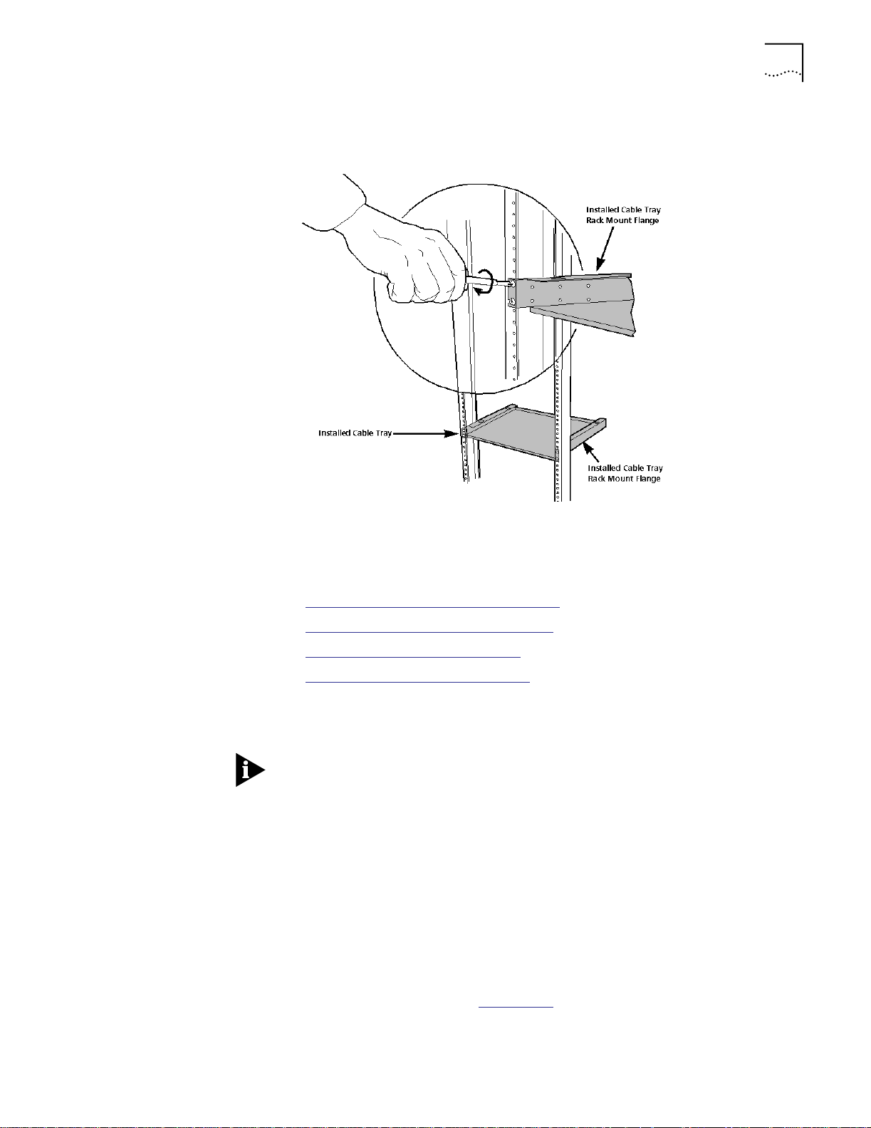
Installing the Hub 3-19
3 Place the cable tray in the rack and attach the cable tray to the front of the rack
using the screws provided (four 10-32 x 1/2-inch screws). Install the screws with
a Philips screwdriver.
Installing the Hub in a
Rack
Figure 3-13 Installing the Cable Tray in a Rack
This section describes:
■ Pre-installation Rack-Mount Precautions
■ Pre-installation Rack-Mount Guidelines
■ Installing the Hub in a Telco Rack
■ Installing the Hub in a Metric Rack
Before installing the CoreBuilder 5000 Integrated System Hub in a rack, review
the information provided in Selecting a Site, earlier in this chapter.
Safety regulations state that the CoreBuilder 5000 Integrated System Hub
featured with a 6000PS-48V Power Supply must only be installed in a rack or
enclosed cabinet.
Use the rack-mount installation guidelines below to ensure safety and optimal
performance. These guidelines apply to all versions of the hub. Review all
guidelines prior to installation.
Pre-installation Rack-Mount Precautions
Before installing the CoreBuilder 5000 Integrated System Hub in an equipment
rack, observe the following precautions:
■ Because the equipment rack environment can cause increased ambient
temperatures and reduced air flow, review the hub specifications and site
requirements contained in Appendix A
.
Page 74

3-20 CHAPTER 3: INSTALLING THE HUB
■ To ensure mechanical stability and to avoid circuit overloading and improper
Pre-installation Rack-Mount Guidelines
Before attempting to rack-mount the CoreBuilder 5000 Integrated System Hub:
1 First make sure the selected rack can support at least three times the weight of
a fully loaded hub.
2 Bolt the rack to the floor.
3 Brace the top of the rack to the wall.
4 Provide sufficient vertical space in your rack for each CoreBuilder 5000
Integrated System Hub you want to install.
5 For proper ventilation, install the hub in a rack that has an open back.
6 Install patch panels in the rack for easier cable management.
7 Continue to support the weight of the hub until after you have installed four of
the eight screws (two screws per rack-mount flange). Install all eight screws
(four screws per rack-mount flange) to fully secure both rack-mount flanges to
the rack.
grounding, follow the rack manufacturer’s instructions for rack installation. If
the instructions are unclear, consult a qualified electrician.
8 Install the cable tray beneath the hub. The cable tray is designed to manage the
cables attached to the front of the hub by feeding them under and through the
back of the unit. Use of the cable tray is optional. You can mount the cable tray
onto the rack in one of four positions. Mount the hub using the same
rack-mount position settings as those used to mount the cable tray.
WARNING: You can install the hub in the rack either before or after you install
the cable tray, but the cable tray must be installed below the hub. Never allow
an installed cable tray to support the weight of the hub. The weight of a hub
resting on a rack-mounted cable tray may cause the cable tray to buckle or
separate from the rack. Personal injury may result.
Installing the Hub in a Telco Rack
All rack-mount illustrations provided in this chapter show the hub installed in a
Tel co rack. Install the screws that secure the hub to the Telco rack in open slots
on each rack-mount flange.
Telco rack and Metric rack screw locations are shown in Figure 3-16
. For
descriptions of Telco and Metric racks, refer to Location Requirements earlier in
this chapter.
Page 75

Installing the Hub 3-21
To install the hub in a Telco rack:
1 Install each of the eight clip nuts provided onto each side of the front of the
rack (four clip nuts per rack-mount flange). Install each clip nut behind a hole
into which you plan to install a trusshead screw. Refer to Figure 3-14
.
WARNING: With a full complement of modules and load-sharing power
supplies, the CoreBuilder 5000 Integrated System 17-slot Hub weighs
approximately 120 lbs. (54 kg), a CoreBuilder 5000 Integrated System 10-slot
Hub weighs approximately 79 lbs. (35.8 kg), and a CoreBuilder 5000 Integrated
System 7-slot Hub weighs approximately 56 lbs. (25.4 kg). Therefore, install your
17-slot, 10-slot, or 7-slot hub before you install modules and power supplies.
Continue to support the weight of the hub until after you have installed four of
the eight screws (2 screws per rack-mount flange) for the 17-slot and the
10-slot hubs only. The 7-slot hub has three rack positions on each side of the
hub.
If you attempt to place the weight of the rack-mounted 17-slot or 10-slot hub
on fewer than four fully installed screws, the hub may drop off of the rack.
Personal injury or serious damage to the hub may result.
2 Slide the hub into the rack until both rack-mount flanges are flush with the
front of the rack.
Figure 3-14
Figure 3-14 Installing a Clip Nut in the Rack
shows the clip nut installation.
Be sure to
thread the
screw through
this nut to
securely attach
each clip nut to
the rack
Rack-mount flanges are set to ’flush mount’ at the factory. If desired, change
the rack-mount flange position by removing the screws that attach each flange
to the hub. When re-installing the rack-mount flanges on the hub, make sure
both flanges are set to the same position before you re-install the screws. Also,
make certain that all removed screws are re-installed correctly.
Page 76

3-22 CHAPTER 3: INSTALLING THE HUB
3 Match the uppermost open slot on each rack-mount flange with the
corresponding hole on the rack (see Figure 3-15
you complete step 4. The remaining three open slots on each rack-mount
flange automatically line up when each uppermost open slot is matched to a
hole on the rack.
4 Secure the hub to the rack with the screws provided (eight 10-32 x 1/2-inch
screws).
a Install one screw in the uppermost open slot on each rack-mount flange (see
b Install the remaining screws in open slots on each rack-mount flange (for a
Installing the Hub in a Metric Rack
To install the hub in a Metric rack (see Figure 3-15
1 Install each of the eight clip nuts provided onto the front of the rack (install four
clip nuts per rack-mount flange). Install each clip nut behind a hole into which
you plan to install a trusshead screw.
). Hold the hub in place until
Figure 3-15
). Install two screws per rack-mount flange before you allow the
weight of the hub to rest (unaided) on the rack. Tighten all screws
completely. A fully installed screw is flush with the surface of each
rack-mount flange.
total of four screws per rack-mount flange). Tighten all screws completely.
):
2 Slide the hub into the rack until the hub is flush with the front of the rack.
3 Match the uppermost closed slot on each rack-mount flange to the uppermost
hole on the rack where you previously installed a clip nut. Do not attempt to
install screws in open slots on either rack-mount flange.
4 Secure the hub to the rack with the screws provided (eight 10-32 x 1/2-inch
screws).
a Install one screw in the uppermost closed slot on each rack-mount flange.
Install two screws per rack-mount flange before you allow the weight of the
hub to rest (unaided) on the rack. Tighten all screws completely. A fully
installed screw is flush with the surface of each rack-mount flange.
When installing the hub in a metric rack, install the screws in the closed slots.
b Install the remaining screws in closed slots on each rack-mount flange (for a
total of four screws per rack-mount flange). Install each screw so it is
(approximately) equidistant from the screw installed directly above it and the
screw installed directly below it. Tighten all screws completely.
WARNING: If you attempt to place the weight of the hub on fewer than four
fully installed screws, the hub may drop off of the rack. Personal injury or
serious damage to the hub may result.
Page 77

Installing the Hub 3-23
Figure 3-15 shows a rack-mounted 17-slot hub with an installed cable tray. The
10-slot hub installation is identical.
Screw position (Telco rack)
Screw position (Metric rack)
Figure 3-15 Rack-mounted 17-slot Hub With Cable Tray
Screw position (Metric rack)
Screw position (Telco rack)
Page 78

3-24 CHAPTER 3: INSTALLING THE HUB
The 7-slot hub has three rack-mount positions. Figure 3-16 shows a
rack-mounted 7-slot hub in the first rack-mount position.
Screw Position
(Metric rack)
Screw Position
(Telco rack)
Figure 3-16 Rack-Mounted 7-slot Hub With Cable Tray
Screw Position
(Telco rack)
Screw Position
(Metric rack)
Page 79

4
INSTALLING POWER SUPPLIES
This chapter describes the installation procedures for the CoreBuilder5000
Integrated System Hub power supplies.
This chapter contains the following sections:
■ CoreBuilder 5000 Intelligent Power Subsystem
■ CoreBuilder 5000 Power Supply Models
■ Determining the Model Number of Your Power Supply
■ Power Requirements
■ Load-Sharing Power Supplies
■ Managing Power in the Hub
■ Installing Power Supplies
■ Installing Power Supply Bay Grilles
CoreBuilder 5000
Intelligent Power
Subsystem
Intelligent Power
Subsystem Features
■ Budgeting Power
■ Saved Power Management Configurations
■ Verifying Power Supply Operation
The CoreBuilder 5000 Integrated System Hub provides a fault-tolerant,
intelligent power supply subsystem. The CoreBuilder 5000 Intelligent Power
Subsystem supports:
■ Load-sharing AC and DC power supplies
■ High power availability
■ Controller-based power verification features designed to ensure optimal
performance
Table 4-1
Table 4-1 Intelligent Power Subsystem Features
Feature Description
Load-sharing power
supplies
describes Intelligent Power Subsystem features.
Provides evenly distributed power consumption among all
installed power supplies. Hub activity is not disrupted if a
power supply fails because there is no changeover (and hence,
no changeover interval).
Page 80

4-2 CHAPTER 4: INSTALLING POWER SUPPLIES
Table 4-1 Intelligent Power Subsystem Features (continued)
Feature Description
Front-load accessibility Provides easy access for upgrades. As your power needs
Dedicated power supply
bay cooling
High power capacity Determines the current power limit. The power mode and the
increase over time, it is easy to upgrade by adding a power
supply into the front of the 10-slot and 17-slot hubs (add
power supplies from the rear of the the 7-slot hub). Because
power supply connectors are keyed to the power distribution
board, replacing a faulty power supply is a short procedure.
Cools the power supply bay. Vent holes on the back of the
CoreBuilder 5000 Integrated System 10-slot and 17-slot Hubs
(vent holes are on the right side of the CoreBuilder 5000
Integrated System 7-slot Hub) reduce the possibility that an
overheat condition in the power supply bay will cause or
contribute to hub or module failure. This feature works with
other hub features to maintain normal hub internal operating
temperature.
amount of power available determine the current power limit.
The actual power delivered depends on whether you are
running in non-fault-tolerant mode or in fault-tolerant mode.
Non-Fault Tolerant Mode:
Depending on the power supply models installed in a
10-slot hub, three power supplies deliver from 885 to
1245 Watts of power to installed modules.
Depending on the power supply models installed in a
17-slot hub, four power supplies deliver from 1180 to
1660 Watts of power to installed modules.
Depending on the power supply models installed in a
7-slot hub, two 295 Watt power supplies deliver from 590 to
705 Watts of power to installed modules and two 415 Watt
power supplies deliver 830 Watts of power to installed
modules.
(For detailed information on power supply capacity, refer to the
sections titled Power Supply Output in Non-Fault-Tolerant Mode
and Power Supply Output in Fault-Tolerant Mode in this
chapter.)
Fault-Tolerant Mode:
Depending on the power supply models installed in a
10-slot hub, three power supplies deliver from 590 to 830
Watts of power to installed modules.
Depending on the power supply models installed in a
17-slot hub, four power supplies deliver from 885 to 1245
Watts of power to installed modules.
Depending on the power supply models installed in a
7-slot hub, two 295 Watt power supplies deliver from 295 to
415 Watts of power to installed modules and two 415 Watt
power supplies deliver 415 Watts of power to installed
modules.
If a power supply fails while the hub is running in fault-tolerant
mode, still-functioning supplies provide all of the power
necessary to keep installed modules and the hub running.
(One power supply capacity is held in reserve.) This is because
the power reserved for fault-tolerance is made available to
modules already powered on. Hence, the failure of a power
supply has no impact to the system.
Page 81

CoreBuilder 5000 Power Supply Models 4-3
Table 4-1 Intelligent Power Subsystem Features (continued)
Feature Description
Controller Module-based
software-driven power
management
Confirms that there is enough power for the CoreBuilder 5000
module. The CoreBuilder 5000 Fault-Tolerant Controller Module
(Model Number 6000M-RCTL or 6000M-CMGT) polls each
new CoreBuilder 5000 module installed in the hub to confirm
enough power is available for the CoreBuilder 5000 module. If
available power is:
Adequate – The new CoreBuilder 5000 module powers on.
Inadequate – The new CoreBuilder 5000 module does not
power on. System overload is avoided.
Software-driven power management (Intelligent Power
Management) also provides protection against the possibility of
a catastrophic power failure. If the hub is operating in power
non-fault-tolerant mode and a power supply fails, installed
Controller Modules power off selected (low power class)
CoreBuilder 5000 modules until the power deficit is corrected.
Intelligent Power Management ensures that key components
and resources continue to operate, even under extreme failure
conditions.
(If the hub is configured with a DMM module, alerts and traps
are sent to the network management applications regarding
any changes.)
CoreBuilder 5000
Power Supply Models
Table 4-2 lists the power supplies supported by the CoreBuilder 5000 Integrated
System Hub.
Table 4-2 CoreBuilder 5000 Integrated System Hub Power Supply Models
Model Number Watts Input Power Type
6000PS 295 AC
6000PS-48V 295 DC
6000PS-HO 415 AC
You can purchase the power supply model numbers that your configuration
requires. You can use any combination of power supplies in your hub, ranging
from all of one type to a mixture of all three types.
Some products may contain the prefix ’3C9’. These are the same as those that
do not contain this prefix.
Full support of the 6000PS-48V and 6000PS-HO power supplies requires that
you load DMM software Version v2.3 or later and Controller software
Version v1.1 or later. Earlier software versions support these models as unknown
295 Watt power supply types.
Page 82
4-4 CHAPTER 4: INSTALLING POWER SUPPLIES
Determining the Model Number of Your Power Supply
After hub installation (refer to Chapter 3), if your hub is managed by a
CoreBuilder 5000 Distributed Management Module, determine the model
number of your power supply to configure your environment appropriately. Each
power supply has its own requirements. To determine the Model Numbers of
your power supplies:
1 Enter the SHOW HUB command.
2 Press Enter.
Chapter 6 provides information about the SHOW HUB command.
For information on how power supplies ship, refer to Chapter 3, the section
titled Second Shipping Box Contents.
Power Requirements This section describes the following power requirements for the
CoreBuilder 5000 Integrated System Hub:
■ AC Power
■ -48 Volt DC Power
Use a dedicated 15 Amperes (Amps) circuit (or an equivalent method of
providing this current) to supply power to installed CoreBuilder 5000 power
supplies when operated at a voltage of between 90 Volts and 130 Volts AC.
This ensures adequate power for a fully loaded hub configuration. This circuit
must be grounded to a safety (protective earth) ground, not to a neutral ground
that carries current back to the transformer.
WARNING: Do not use electrical conduit pipe as your only means of grounding
the hub.
When you use a single circuit to power multiple load-sharing power supplies,
that single circuit may be required to deliver more than 15 Amps. This depends
on the number of installed power supplies and on the voltage configuration.
Load-sharing power supplies always draw power when inserted into the hub.
There is no low-power standby mode of operation.
WARNING: For use in Denmark, each 6000PS-HO power supply must receive
power from a separately dedicated socket outlet having a 16 Amp fuse in the
installation.
WARNING: Ved brug i Danmark, skal hver 6000PS-HO stromforsyning
modtage strom fra en separat, dedikeret stikkontakt med en 16 Amp sikring i
installationen.
AC Power Requirements CoreBuilder 5000 load-sharing AC power supplies are autosensing. Each power
supply can automatically sense (identify) the type of input AC voltage to which
it is being connected at the wall outlet. Compatible voltages are as follows:
■ Europe – 220 Volts to 240 Volts
■ North America – 110 Volts to 220 Volts
■ Japan – 100 Volts
Page 83

DC Power Requirements The -48 Volt DC power supply must provide:
■ Voltage range – -40 Volts to -57 Volts
■ Permanent power for 1 DC supply – 11 Amps
■ Inrush current for 1 DC supply – 60 Amps and 16 Amps within 16 ms. To
accept the inrush current, use a 100 Amps source to feed up to four -48 Volt
DC power supplies.
CAUTION: Use only the power cord supplied in the -48 Volt DC power supply
shipping box. Only qualified service personnel should install the power cord to
the DC power source.
For instructions on how to install the -48 Volt DC input power cord, refer to the
section titled Installing the -48 Volt DC Power Supply and Power Cord later in
this chapter.
Load-Sharing Power Supplies 4-5
Load-Sharing Power Supplies
This section describes available power modes and power supply capacity in each
power mode.
Table 4-3
lists the number of power supplies each CoreBuilder 5000 Integrated
System Hub can accommodate.
Table 4-3 Number of Power Supplies in Each CoreBuilder 5000 Hub
This CoreBuilder 5000 Integrated System
Hub...
17-slot 4
10-slot 3
7-slot 2
Can accomodate this number of power
supplies....
CoreBuilder 5000 Integrated System Hubs can ship with or without power
supplies. For information on how hubs are shipped, refer to Chapter 3, the
section titled Removing the Hub and Components From the Shipping Boxes.
Power Supply Modes The CoreBuilder 5000 Integrated System Hub runs in either of two power supply
output modes:
■ Power Non-Fault-Tolerant Mode
■ Power Fault-Tolerant Mode
The following sections describe:
■ Power Supply Modes
■ Power Availability and Power Supply Capacity
For optimal power redundancy in either power mode, run the hub with at least
one power supply more than the minimum number required to operate all
installed modules and all modules you plan to install.
Page 84

4-6 CHAPTER 4: INSTALLING POWER SUPPLIES
Power Non-Fault-Tolerant Mode
Power non-fault-tolerant mode is:
■ A user-selectable mode in which 100 percent of the power that can be
allocated to modules is available to them (no power is held in reserve).
■ The default mode for power supplies as shipped.
While the hub is running in power non-fault-tolerant mode, the amount of
power available to modules is determined by the number and type of installed
power supplies. For example, if your hub is in non-fault-tolerant mode and has
a mixture of 415 Watt (6000PS-HO) and 295 Watt (6000PS and 6000PS-48V)
power supplies, the 415 Watt power supplies deliver 415 Watt and the
295 Watt power supplies deliver 295 Watts.
If a power supply fails while the hub is running in power non-fault-tolerant
mode:
■ Installed Controller modules may shut down selected CoreBuilder 5000
modules in an attempt to bring installed module power consumption under
the now-reduced power budget.
■ Installed modules continue to operate without interruption if the output of
at least one installed power supply is not required by installed modules when
a power supply fails.
For more information, refer to Chapter 2, the section titled CoreBuilder 5000
Module Power-Down Response.
CAUTION: When switching on power supplies in a hub containing ONline
modules, switch all installed power supplies on simultaneously to avoid the
possible shutdown of one or more power supplies. This is necessary only when
the power required by installed ONline modules is greater than the capacity of
the first power supply you switch on. For example, if you switch on one power
supply at a time, the first power supply you switch on may get overloaded and
shut down before a second power supply can power up and share the load.
Also, if a power supply shuts down due to an overload, be aware that you must
wait at least 10 seconds before attempting to switch that power supply on
again.
Power Fault-Tolerant Mode
Power fault-tolerant mode is a user-selectable mode in which one power
supply’s worth of power is held in reserve. This reserve power is not available to
installed modules until a power supply fails, or until the user switches the power
mode from power fault-tolerant mode to power non-fault-tolerant mode.
While the hub is running in power fault-tolerant mode:
■ All installed power supplies are functioning and contributing power to the
hub. No single power supply is a dedicated standby power supply. Rather, a
factory-defined power limit (based on the number of installed power
supplies) ensures that at least one power supply’s worth of power is available
to replace power lost when a power supply fails.
Page 85

Load-Sharing Power Supplies 4-7
■ The amount of power required by installed modules must not be greater
than the number of installed power supplies minus one (N-1). When you
reserve one power supply’s worth of power in power fault-tolerant mode,
the failure of a single power supply has no impact on installed modules
already powered up.
If your hub has a mixture of 415 Watt (6000PS-HO) and 295 Watt (6000PS
and/or 6000PS-48V) power supplies (only in fault-tolerant mode), the 415 Watt
power supplies are treated as if they were 295 Watt supplies. In most cases, it is
not to your advantage to mix 415 Watt and 295 Watt power supplies when
running in fault-tolerant mode.
If a power supply fails while the hub is running in power fault-tolerant mode:
■ Active and Standby Controller Modules respond by automatically disabling
power fault-tolerant mode.
■ Power formerly reserved (unavailable to installed modules) is made available
to power enabled CoreBuilder 5000 modules to prevent them from powering
down by power class and slot location (as an attempt to bring power
consumption under the now-reduced power budget).
Power Availability and
Power Supply Capacity
■ All modules that had power before the power supply failure continue to
receive power without interruption.
■ Upon power supply recovery, power fault-tolerant mode is automatically
re-enabled.
To prevent Active and Standby Controller Modules from automatically disabling
power fault-tolerant mode in response to a power supply failure, ensure that
the number of installed power supplies is equal to or greater than N-2 (two
extra power supplies). In a hub with at least two extra installed power supplies,
N-1 power supplies continue to be available to run the hub in power
fault-tolerant mode, even after a single power supply fails. If a power supply
failure occurs under any condition, an alarm is sent to the Network
Management applications.
This section explains the following concepts concerning power supply
management:
■ Power available to modules – The amount of power available to modules
is determined by the number and type of installed power supplies.
■ Power capacity of a power supply – The power capacity of a power
supply unit is the amount of power the power supply delivers. For example,
the 415 Watt power supply delivers 415 Watts and the 295 Watt supply
delivers 295 Watts.
When managing power in your system, consider the system overhead, that is,
the power consumed by the hub itself (fans, TriChannel signalling, Controller
Module). Before installing any new module into a hub, you should assess the
power budget by calculating the total power requirements for all installed
modules, fans, and controllers.
Page 86

4-8 CHAPTER 4: INSTALLING POWER SUPPLIES
Refer to the documentation supplied with each module to determine your
module power requirements. Take into account any modules you plan to install,
as well as those already installed.
System overhead amount consumes 18 Watts of the +12 Voltage and 1 Watt of
the +5 Voltage.
Managing Power in the Hub
The Controller Module provides comprehensive power management for the
CoreBuilder 5000 Integrated System Hub and all installed CoreBuilder 5000
modules.
ONline modules cannot be power managed, but an installed Master DMM
(Distributed Management Module) maintains an ONline module power
consumption table. This table lists power consumption values for specific ONline
module types (for example, a BNC Module). The Master DMM provides these
ONline power consumption values to installed Controller Modules so the
Controller Modules can maintain an accurate power budget.
For more information, refer to Appendix B, ONline Module Power Consumption
and Voltages and Watts Consumed Per Module.
For more information about the DMM commands discussed below, refer to the
CoreBuilder 5000 Distributed Management Module Commands Guide.
This section describes:
■ Establishing Power Fault-Tolerance
■ Power Supply Output in Non-Fault-Tolerant Mode
■ Power Supply Output in Fault-Tolerant Mode
■ Enabling and Disabling Power to Slots
Establishing Power
Fault-Tolerance
■ CoreBuilder 5000 Module Power Class Settings
Operate the hub in power fault-tolerant mode to ensure that at least one
supply’s worth of power is available to replace power lost when and if a single
power supply fails.
To set the hub to power fault-tolerant mode or power non-fault-tolerant mode,
enter the SET POWER MODE command at the DMM prompt.
When you attempt to set the hub to power fault-tolerant mode, Active and
Standby Controller Modules determine if there is sufficient unallocated power
budget available to place one power supply’s worth of power in reserve.
■ If there is sufficient unallocated power budget, the hub sets to power
fault-tolerant mode.
■ If there is insufficient unallocated power budget, the hub remains in power
non-fault-tolerant mode.
Page 87

Managing Power in the Hub 4-9
Determining Hub Power Budget
To ensure optimal power fault-tolerance, determine the current power budget
for the hub as follows:
1 If you have installed a CoreBuilder 5000 Distributed Management Module in
your hub, enter the SHOW POWER BUDGET command at the terminal prompt.
The SHOW POWER BUDGET command shows the amount of power currently
available for modules:
■ Total power installed
■ Amount of power consumed
■ Amount of power available
Compare this information with the power requirements for each module
installed in the hub. Refer to the documentation supplied with each module to
determine your module power requirements. Take into account any modules you
plan to install, as well as those already installed.
Power supply output values displayed by the SHOW POWER BUDGET command
have been rounded down. Therefore, these values may not precisely match
those provided in the documentation shipped with each power supply.
Power Supply Output
in Non-Fault-Tolerant
Mode
2 Examine the output of the SHOW POWER BUDGET command. If necessary, add
another power supply to your hub.
If your software version of the DMM is earlier than software Version v2.3, any
6000PS-HO or 6000PS-48V power supplies you are using are interpreted as
unknown 295 Watt power supply types.
In the power supply output tables below, values are rounded values that do not
include system overhead (fans, TriChannel signalling, and two installed
Controller Modules).
Table 4-4
shows the power available in power non-fault-tolerant mode (by
voltage type) when the power supplies are 295 Watts, AC (Model
Number 6000PS) or DC (Model Number 6000PS-48V). Power output for the
-48 Volt DC power supply is identical to the 295 Watt AC power supply.
Table 4-4 Power Capacity for Modules in Power Non-Fault-Tolerant Mode (295 Watts)
One Power
Output Voltage
(Volts)
+5 204.00 366.00 549.00 732.00
-5 15.00 25.50 38.25 51.00
+12 48.00 81.00 121.50 162.00
-12 18.00 30.50 45.75 61.00
+2 8.40 14.20 21.30 28.40
TOTAL WATTS 293.40 517.20 775.80 1034.4
Supply
(Watts)
Two Power
Supplies
(Watts)
Three Power
Supplies
(Watts)
Four Power
Supplies
(Watts)
Page 88

4-10 CHAPTER 4: INSTALLING POWER SUPPLIES
The raw power output for the 6000PS (AC) power supply and the 6000PS-48V
power supply (DC) are both 295 Watt power supplies, but one is AC input and
the other is DC input.
Table 4-4
shows the power available in power non-fault-tolerant mode (by
voltage) when the power supplies are Model Number 6000PS-HO
(415 Watt AC).
Table 4-5 Power Capacity for Modules in Power Non-Fault-Tolerant Mode (415 Watts)
Four
One Power
Output Voltage
(Volts)
+5 301.00 542.00 813.00 1084.00
-5 15.00 25.50 38.25 51.00
+12 72.00 122.00 183.00 244.00
-12 18.00 30.50 45.75 61.00
+2 8.40 14.20 21.30 28.40
TOTAL WATTS 414.40 734.20 1101.30 1468.40
Table 4-6
■ The number of power supplies required in power non-fault-tolerant mode (by
shows:
Supply
(Watts)
Two Power
Supplies
(Watts)
Three Power
Supplies
(Watts)
Power
Supplies
(Watts)
voltage type) when the hub contains a mixture of 295 Watt and 415 Watt
power supplies. References to 295 Watts in this table correspond to Model
Numbers 6000PS and 6000PS-48V power supplies. The raw power output
for the 6000PS and the 6000PS-48V is identical (295 Watt).
■ The combinations of power supply types and the numbers of required power
supplies defined as A through F. (Use the key as a reference tool for the
power information described in Table 4-6
Table 4-6 Power Supply Requirements
Power Supply Combination
Key
A One 415 and one 295 2
B One 415 and two 295 3
C Two 415 and one 295 3
D One 415 and three 295 4
E Two 415 and two 295 4
F Three 415 and one 295 4
(Watts)
through Table 4-10.)
Total Number of Power
Supplies
Page 89

Managing Power in the Hub 4-11
Table 4-7 shows the amount of power available to modules in non-fault-tolerant
mode and the number of power supplies required when you mix 415 Watts and
295 Watts (AC or DC input) power supplies.
Table 4-7 Power Capacity for Modules in Non-Fault-Tolerant Mode (Mixed 295 and
415 Watts)
Output
Voltage
Power Supply
Type and
Number of
Power
Supplies
+5 454.00 637.00 725.00 820.00 908.00 996.00
-5 25.50 38.25 38.25 51.00 51.00 51.00
+12 101.50 142.00 162.50 182.50 203.00 223.50
-12 30.50 45.75 45.75 61.00 61.00 61.00
+2 14.20 21.30 21.30 28.40 28.40 28.40
TOTAL WATTS 625.70 884.30 992.80 1142.90 1251.40 1359.90
A B C D E F
415 295
1 1
415 295
1 2
415 295
2 1
415 295
1 3
415 295
2 2
415 295
3 1
Power Supply Output
in Fault-Tolerant Mode
In the power supply output tables below, values are rounded values that do not
include system overhead (fans, TriChannel signalling, and two installed
Controller Modules).
Table 4-8
shows the power available in power fault-tolerant mode (by voltage)
when the power supplies are 295 Watts, AC (Model Number 6000PS) or
295 Watts, DC (Model Number 6000PS-48V).
Table 4-8 Power Capacity for Modules in Power Fault-Tolerant Mode (295 Watts)
Four
One Power
Output Voltage
(Volts)
+5 N/A 204.00 366.00 549.00
-5 N/A 15.00 25.50 38.25
+12 N/A 48.00 81.00 121.50
-12 N/A 18.00 30.50 45.75
+2 N/A 8.40 14.20 21.30
TOTAL WATTS N/A 293.40 517.20 775.80
1
Power fault-tolerance can only be established if at least one power supply’s worth of
unallocated power budget is available to be held in reserve.
Supply
(Watts)
1
Two Power
Supplies
(Watts)
Three Power
Supplies
(Watts)
Power
Supplies
(Watts)
The raw power output for the 6000PS (AC) power supply and the 6000PS-48V
power supply (DC) are both 295 Watt power supplies, but one is AC input and
the other is DC input.
Page 90

4-12 CHAPTER 4: INSTALLING POWER SUPPLIES
Table 4-8 shows the power available in power fault-tolerant mode (by voltage)
when the power supplies are 415 Watt AC (Model Number 6000PS-HO).
Table 4-9 Power Capacity for Modules in Power Fault-Tolerant Mode (415 Watts)
One Power
Output Voltage
(Volts)
+5 N/A 301.00 542.00 813.00
-5 N/A 15.00 25.50 38.25
+12 N/A 72.00 122.00 183.00
-12 N/A 18.00 30.50 45.75
+2 N/A 8.40 14.20 21.30
TOTAL WATTS N/A 414.40 734.20 1101.30
1
Power fault-tolerance can only be established if at least one power supply’s worth of
unallocated power budget is available to be held in reserve.
Table 4-10
shows the amount of power available to modules in fault-tolerant
Supply
(Watts)
1
Two Power
Supplies
(Watts)
Three Power
Supplies
(Watts)
Four Power
Supplies
(Watts)
mode and the number of power supplies required when you mix 415 Watts and
295 Watts (AC or DC input) power supplies.
Table 4-10 Power Capacity for Modules in Fault-Tolerant Mode (Mixed 295 and
415 Watts)
Output Voltage A B C D E F
Power Supply
Type and
Number of
Power Supplies
+5 204.00 366.0 366.0 549.0 549.0 549.0
-5 15.0 25.5 25.5 38.3 38.3 38.3
+12 48.0 81.0 81.0 121.5 121.5 121.5
-12 18.0 30.5 30.5 45.8 45.8 45.8
+2 8.4 14.2 14.2 21.3 21.3 21.3
TOTAL WATTS 293.4 517.2 517.2 775.9 775.9 775.9
415 295
1 1
415 295
1 2
415 295
2 1
415 295
1 3
415 295
2 2
415 295
3 1
Enabling and Disabling
Power to Slots
In summary, you can establish power fault-tolerant mode only if:
■ Power budget consumed is less than or equal to the power delivery
capability provided by N-1 power supplies.
■ The hub is managed by an installed CoreBuilder 5000 Distributed
Management Module.
If you have an installed Distributed Management Module (DMM), you can use
CoreBuilder 5000 power management commands to enable or disable power to
any selected slot containing a CoreBuilder 5000 module. Installed Controller
Modules allow you to enable power to a slot, but only if there is sufficient
unallocated power budget to power up the module installed in the slot.
Page 91

Managing Power in the Hub 4-13
This section describes:
■ Power Enabled State
■ Power Disabled State
Power Enabled State
To enable power to a specified slot:
1 Enter the SET POWER SLOT MODE ENABLE command.
2 Press Enter.
If there is:
■ Sufficient power available to meet the requirements of the
CoreBuilder 5000 module, installed Controller Modules enable power to
the specified slot and reduce the power budget by the amount of power
the CoreBuilder 5000 module installed in that slot consumes.
■ Insufficient power to meet the requirements of the CoreBuilder 5000
module, the CoreBuilder 5000 module remains in power pending state
until sufficient power becomes available.
A CoreBuilder 5000 module that was powered down due to a lack of sufficient
available power is in power pending state. The module can be automatically
powered up again by installed Controller Modules when sufficient power
becomes available.
Power Disabled State
A CoreBuilder 5000 module in power disabled state is a CoreBuilder 5000
module that was powered down. A CoreBuilder 5000 module in power disabled
state is not eligible to be automatically powered up again when sufficient
power becomes available.
To disable power to a CoreBuilder 5000 module in a specified slot:
1 Enter the SET POWER SLOT MODE DISABLE command.
2 Press Enter.
Upon disabling power to a slot containing a CoreBuilder 5000 module, the
power previously consumed by the CoreBuilder 5000 module is returned to the
unallocated power budget (that is, to the power available budget).
ONline Management Modules do not provide a user interface to Controller
Module power management functionality.
Page 92

4-14 CHAPTER 4: INSTALLING POWER SUPPLIES
CoreBuilder 5000
Module Power Class
Settings
A power class setting is a user-definable value ranging from 1 through 10
(10 is the highest possible power class setting). You can define the power class
setting for any installed CoreBuilder 5000 module to make one
CoreBuilder 5000 module more important or less important than another.
Installed Controller Modules use default and user-defined power class settings to
make power management decisions. For example, installed Controller Modules
use CoreBuilder 5000 module power class settings to determine the order in
which installed CoreBuilder 5000 modules power up and power down under
certain power deficit and overheat conditions.
This section describes:
■ Using the Default Power Class Setting
■ Setting Power Class Manually
■ Power Class 10 Warnings
Using the Default Power Class Setting
Each CoreBuilder 5000 module is shipped with a default power class setting
of 3.
■ Assign higher power class settings to all installed DMMs, and assign the
highest power class setting of any installed CoreBuilder 5000 module to the
Master DMM. This assures that the Master DMM powers down last (after all
other installed CoreBuilder 5000 modules).
■ Assign a higher power class setting to any CoreBuilder 5000 module
connected to critical network resources.
Setting Power Class Manually
To set the power class for a CoreBuilder 5000 module in a specified slot:
1 Enter the SET POWER SLOT CLASS command.
2 Press Enter.
Refer to the CoreBuilder 5000 Distributed Management Module Commands
Guide for a discussion of this feature.
Even though it has a power class setting, a Controller Module cannot be power
managed. A Controller Module always draws power when inserted in the hub,
and a Controller Module cannot be powered down using a DMM command.
Power Class 10 Warnings
A CoreBuilder 5000 module assigned a power class setting of 10 cannot be
automatically powered down by installed Controller modules.
For example, if a power supply failure causes a power deficit (or if a hub
overheat condition develops while OVERHEAT_AUTO_POWER_DOWN is
enabled), a CoreBuilder 5000 module assigned a power class setting of
10 continues to run until you order it to shut down. Under some conditions
(such as an extended overheat condition), hub or module hardware damage
may result.
Page 93

Installing Power Supplies 4-15
To ensure that installed Controller Modules are able to automatically make all
power management decisions without waiting for user intervention, do not
assign a power class setting of 10 to any CoreBuilder 5000 module unless
absolutely necessary.
Installing Power Supplies
Installing a
Load-Sharing AC Power
Supply
This section contains the following topics:
■ Installing a Load-Sharing AC Power Supply
■ Installing a -48 Volt DC Power Supply and Power Cord
■ Removing a -48 Volt DC Input Power Supply and Power Cord
Due to regulatory safety issues, a -48V DC power supply can only exist in a rack
or an enclosed cabinet. As a result of this placement restriction, a
CoreBuilder 5000 hub containing both an AC power supply and a -48V DC
power supply must be installed in an enclosed cabinet or in a rack. Table or
shelf-mounted CoreBuilder 5000 hubs cannot contain -48V DC power supplies.
To ensure optimal power redundancy, determine current hub power
requirements. For more power requirement information, refer to the section
titled Allocating Sufficient Power for Installed Modules, later in this chapter.
You can install power supplies in any of the power supply slots. A factory label
located directly below the power supply slots identifies the slot number
associated with each power supply.
For important recommendations on power monitoring, reporting, and
maintenance, refer the section titled Managing Power in the Hub earlier in this
chapter.
For the 7-slot hub, power supplies are installed using the same procedures
except you install the power supply horizontally instead of vertically. A label is
affixed to the power supply to identify the ON ( ) position of the power supply
switch.
Page 94

4-16 CHAPTER 4: INSTALLING POWER SUPPLIES
Figure 4-1 shows the location of the label for the ON ( ) position for the 7-slot
hub power supply.
ON/OFF
label for the
power supply
in a 7-slot
hub is located
in this area
Figure 4-1 Location of the ON Position Label for 7-slot Hubs
To add a power supply to the CoreBuilder 5000 Integrated System Hub:
1 Remove the blank faceplate covering each slot in which you will install a power
supply. Keep this blank faceplate for later use.
2 Set the ON/OFF ( / Ο ) switch on the front of the power supply you are
installing to the OFF ( Ο ) position before inserting the power supply into the
hub.
3 Slide the power supply into the selected power supply slot. Push the power
supply unit into the hub until the front panel of the power supply is flush with
the front of the hub. The rear power supply connectors should now be firmly
seated into the hub power supply connectors.
Page 95

Installing Power Supplies 4-17
Figure 4-2 shows how to install a power supply in a 17-slot hub.
Figure 4-2 Installing a Load-Sharing Power Supply in a 17-slot Hub
Figure 4-3 shows how to install a power supply in a 10-slot hub.
Figure 4-3 Installing a Load-Sharing Power Supply in a 10-slot Hub
Page 96

4-18 CHAPTER 4: INSTALLING POWER SUPPLIES
Figure 4-4 shows how to install a power supply in a 7-slot hub.
Screws on the
power supply
Slide the
power supply
into the
selected slot
as shown
here
Figure 4-4 Installing a Load-Sharing Power Supply in a 7-slot Hub
4 Fasten the power supply to the hub by tightening the two screws on the power
supply faceplate. Ensure that both screws are securely fastened (tighten the
screws to Torque Specification 3 to 5 inch pounds).
5 Plug the power cord into the power supply socket.
6 Plug the power cord into the wall outlet.
7 Set the power supply’s ON/OFF switch ( / Ο ) to the ON ( ) position.
Optionally, wait until all modules are installed before setting the switch to the
ON ( ) position.
CAUTION: When switching on power supplies in a hub containing ONline
modules, switch on all installed power supplies simultaneously to avoid the
possible shutdown of one or more power supplies. This is necessary only when
the power required by installed ONline modules is greater than the capacity of
the first power supply you switch on. For example, if you switch on one power
supply at a time, the first power supply you switch on may overload and shut
down before a second power supply can power up and share the load. Also, if
a power supply shuts down due to an overload, be aware that you must wait at
least 10 seconds before attempting to switch on that power supply again.
The power supply should now be fully operational.
CAUTION: When one or more power supplies are active, module and power
supply slots carry electric current. To avoid possible electric shock and damage
to hub components, do not place hands, tools, or other objects (other than
properly installed modules and power supplies) into exposed module or power
supply slots. Do not allow liquids of any kind to contact exposed slots.
Page 97

Installing Power Supplies 4-19
Installing a -48 Volt DC
Power Supply and
Power Cord
This section describes how to prepare and install a -48 Volt DC power supply
and power cord in your hub. The -48 Volt DC power supply is a DC version of
the AC 295 Watt power supply and provides the identical power output of the
6000PS power supply.
The DC input cable ships with the 6000PS-48V power supply.
WARNING: Only trained electrical service personnel should make connections
and disconnections to the -48 Volt DC power source.
A circuit breaker (short-circuit protection) must be set up in the main power
source. This circuit must be grounded to a safety ground (protected earth). For
each power supply use one 20 Amp protection device to protect the cabling
of the -48 Volt DC power supply against short circuits.
WARNING: To comply with UL requirements, the -48 Volt DC power supply
must only be installed in a rack-mounted CoreBuilder 5000 hub or a
CoreBuilder 5000 hub installed in an enclosed cabinet.
CAUTION: The -48 Volt power supply switch only shuts off the output side of
the power supply.
Before You Begin
You must read the notices in this section before you install the -48 Volt DC
power supply and power cord.
CAUTION: Connect the -48 Volt DC power supply to Safety Extra Low Voltage
supply (SELV) only. Carefully read the safety label attached to the power supply
unit you received.
WARNING: Make certain that the building power source is turned OFF (circuit
breaker is in the OFF position).
Before you install the -48 Volt DC power supply:
1 Verify that the power source is compatible with the voltage and tolerances
specified on the input rating plate located on the power supply unit. The
nominal value is -48 Volt DC, 11 Amps.
2 Remove the following items from the shipping box:
a Power supply
b Power input cable
c Terminal rings
The -48 Volt DC power supply ships with different size terminal rings. One
terminal ring is for only the green/yellow ground wire. The remaining terminal
rings are used with the red and black wires. Choose the correct terminal rings
to support your installation.
The AMP part number for the terminal crimping tool is AMP Number 58433-2
(this includes the correct crimping die set). The AMP Die Set part number is
58423-1 (if you already have the crimping tool with other dies).
Page 98

4-20 CHAPTER 4: INSTALLING POWER SUPPLIES
3 Set the power supply ON/STANDBY switch to the Standby position
(see Figure 4-5
).
Figure 4-5
ON/STANDBY switch.
STANDBY position
ON/STANDBY
switch
shows the front panel of the -48 Volt DC power supply with the
Serial number label
Input rating label
Warnings label
Keyed connector
ON position
Figure 4-5 -48 Volt DC Power Supply
The following terminal ring installation shows how you install terminal rings to
the power cord. The installer should adapt the building DC input and make the
power cord connection using the terminal rings shipped with the power supply
or whatever method is necessary to meet system installation requirements. For
compatibility with the building power source, the installer chooses which size
terminal rings should be crimped on the power cord wires.
Preparing and Installing the DC Input Power Cord
To prepare and install the -48 Volt DC input power cord:
1 Obtain the power supply cable that you removed from the shipping box. The
input power cable has three groups of wires. Each wire is labeled with the
corresponding voltage. The two red wires are labeled 48VDC and the two black
wires are labeled 0VDC.
Page 99

Installing Power Supplies 4-21
Figure 4-6 shows the 6000PS-48V Power Supply input power cord.
2 red wires (-48 Volt DC)
1 green/yellow ground wire
2 black wires (0 Volt return)
Figure 4-6 -48 Volt DC Input Power Cord
To comply with UL requirements, the power cord must be routed through a rack
or cabinet raceway to the rack or cabinet distribution panel delivering the -48
Volt DC input power. The cable may be routed to the back using the cable tray
option of the CoreBuilder 5000 hub.
Safety label
Keyed connector
CAUTION: You must install the green/yellow ground wire first.
2 Fit the appropriate terminal rings to each wire of the power cord and tighten
them with a crimping tool according to the AMP rings size. Each wire has a
terminal ring at the end (see Figure 4-7
).
The AMP part number for the terminal crimping tool is AMP Number 58433-2
(this includes the correct crimping die set). The AMP Die Set part number
is 58423-1 (if you already have the crimping tool with other dies).
Terminal ring
Figure 4-7 Terminal Ring on Each Wire
3 Connect the cable ground wire (green/yellow) to the ground terminal lugs.
The power source should be labeled with minus (-) and positive (+) symbols.
4 Take the two black wires and connect the two black wires to the positive (+)
symbol on the power source (zero Volt return).
Page 100

4-22 CHAPTER 4: INSTALLING POWER SUPPLIES
5 Take the two red wires and connect the two red wires to the minus (-) symbol
of the power source (-48 Volt).
Installing the -48 Volt DC Power Supply
To install the -48 Volt DC power supply:
1 Make certain that the power supply’s ON/STANDBY switch is in the STANDBY
position.
2 After removing a blank faceplate that covers a power supply slot, carefully slide
the power supply into the selected slot of the CoreBuilder 5000 hub chassis.
3 Fasten the power supply to the hub by tightening the two spring-loaded screws
on the power supply faceplate. Ensure that both screws are securely fastened
(tighten the screws to Torque Specification 3 to 5 inch pounds).
4 Plug the keyed cable connector into the power supply socket (see Figure 4-8).
Removing a -48 Volt DC
Input Power Supply
and Power Cord
Figure 4-8
Figure 4-8 Keyed Cable Connector
shows the keyed connector on the -48 Volt DC input power cord.
5 Turn on the -48 Volt building power source.
6 Set the power supply’s ON/STANDBY switch to the ON ( ) position and follow
the normal operating procedure of your CoreBuilder 5000 hub.
7 Install the power supply bay grille into the CoreBuilder 5000 hub. For this
procedure, refer to the section titled Installing Power Supply Bay Grilles.
CAUTION: Only trained electrical service personnel should make connections
and disconnections to the -48 Volt DC power source.
To remove the -48 Volt DC input power supply and power cord:
1 Remove the power supply bay grille.
2 Set the power supply ON/STANDBY switch to the STANDBY position.
3 Turn off the building power source circuit breaker, protecting the power supply
you want to remove.
4 Unplug and remove the keyed cable connector from the power supply socket.
5 Loosen the spring-loaded screws on the power supply faceplate.
6 Carefully pull out the power supply from the slot of the CoreBuilder 5000 hub
chassis.
 Loading...