


CoreBuilder™ 5000
®
Ethernet 36-Port 10BASE-T
Module User Guide
http://www.3com.com/
Document Number 17-00629-3
Published May 1997

3Com Corporation
5400 Bayfront Plaza
Santa Clara, California
95052-8145
Copyright © 3Com Corporation, 1997. All rights reserved. No part of this documentation may be
reproduced in any form or by any means, or used to make any derivative work (such as translation,
transformation, or adaptation) without permission from 3Com Corporation. Portions of this document are
reproduced in whole or part with permission from third parties.
3Com Corporation reserves the right to revise this documentation and to make changes in content from
time to time without obligation on the part of 3Com Corporation to provide notification of such revision or
change.
3Com Corporation provides this documentation without warranty of any kind, either implied or expressed,
including, but not limited to, the implied warranties of merchantability and fitness for a particular purpose.
3Com may make improvements or changes in the products or programs described in this documentation at
any time.
UNITED STATES GOVERNMENT LEGENDS:
If you are a United States government agency, then this documentation and the software described herein
are provided to you subject to the following restricted rights:
For units of the Department of Defense:
Restricted Rights Legend: Use, duplication, or disclosure by the Government is subject to restrictions as set
forth in subparagraph (c) (1) (ii) for Restricted Rights in Technical Data and Computer Software Clause at
48 C.F.R. 52.227-7013.
For civilian agencies:
Restricted Rights Legend: Use, reproduction, or disclosure is subject to restrictions set forth in subparagraph
(a) through (d) of the Commercial Computer Software – Restricted Rights Clause at 48 C.F.R. 52.227-19
and the limitations set forth in the 3Com Corporation standard commercial agreement for the software.
Unpublished rights reserved under the copyright laws of the United States.
If there is any software on removable media described in this documentation, it is furnished under a license
agreement included with the product as a separate document, in the hardcopy documentation, or on the
removable media in a directory file named LICENSE.TXT. If you are unable to locate a copy, please contact
3Com and a copy will be sent to you.
Federal Communications Commission Notice
This equipment was tested and found to comply with the limits for a Class A digital device, pursuant to
Part 15 of the FCC Rules. These limits are designed to provide reasonable protection against harmful
interference when the equipment is operated in a commercial environment. This equipment generates,
uses, and can radiate radio frequency energy and, if not installed and used in accordance with the
instruction manual, may cause harmful interference to radio communications. Operation of this equipment
in a residential area is likely to cause harmful interference, in which case you must correct the interference
at your own expense.
Canadian Emissions Requirements
This Class A digital apparatus meets all requirements of the Canadian Interference-Causing Equipment
Regulations.
Cet appareil numérique de la classe A respecte toutes les exigences du Règlement sur le matériel brouilleur
du Canada.
EMC Directive Compliance
This equipment was tested and conforms to the Council Directive 89/336/EEC for electromagnetic
compatibility. Conformity with this directive is based upon compliance with the following harmonized
standards:
EN 55022 – Limits and Methods of Measurement of Radio Interference
EN 50082-1 – Electromagnetic Compatibility Generic Immunity Standard: Residential, Commercial, and
Light Industry
Warning: This is a Class A product. In a domestic environment, this product may cause radio interference, in
which case you may be required to take adequate measures.
Compliance with this directive depends on the use of shielded cables.
Low Voltage Directive Compliance
This equipment was tested and conforms to the Council Directive 72/23/EEC for safety of electrical
equipment. Conformity with this directive is based upon compliance with the following harmonized
standard:
EN 60950 – Safety of Information Technology Equipment
ii

VCCI Class 1 Compliance
This equipment is in the 1st Class category (information equipment to be used in commercial or industrial
areas) and conforms to the standards set by the Voluntary Control Council for Interference by Information
Technology Equipment aimed at preventing radio interference in commercial or industrial areas.
Consequently, when the equipment is used in a residential area or in an adjacent area, radio interference
may be caused to radio and TV receivers, and so on.
Read the instructions for correct handling.
Fiber Cable Classification Notice
Use this equipment only with fiber cable classified by Underwriters Laboratories as to fire and smoke
characteristics in accordance with Section 770-2(b) and Section 725-2(b) of the National Electrical Code.
UK General Approval Statement
The CoreBuilder 5000 Integrated System Hub and ONline System Concentrator are manufactured to the
International Safety Standard EN 60950 and are approved in the U.K. under the General Approval Number
NS/G/12345/J/100003 for indirect connection to the public telecommunication network.
Trademarks
Unless otherwise indicated, 3Com registered trademarks are registered in the United States and may or may
not be registered in other countries.
3Com, Boundary Routing, CardFacts, EtherLink, LANplex, LANsentry, LinkBuilder, NETBuilder, NETBuilder II,
NetFacts, Parallel Tasking, SmartAgent, TokenDisk, TokenLink, Transcend, TriChannel, and ViewBuilder are
registered trademarks of 3Com Corporation.
3TECH, CELLplex, CoreBuilder, EtherDisk, EtherLink II, FDDILink, MultiProbe, NetProbe, and ONline are
trademarks of 3Com Corporation.
3ComFacts is a service mark of 3Com Corporation.
The 3Com Multichannel Architecture Communications System is registered under U.S. Patent
Number 5,301,303.
AT&T is a registered trademark of American Telephone and Telegraph Company.
Banyan and VINES are registered trademarks of Banyan Systems Inc.
CompuServe is a registered trademark of CompuServe, Inc.
DEC, DECnet, DELNI, POLYCENTER, VAX, VT100, VT220, and the Digital logo are trademarks of Digital
Equipment Corporation.
Hayes is a registered trademark of Hayes Microcomputer Products.
OpenView is a registered trademark of Hewlett-Packard Company.
Intel is a registered trademark of Intel Corporation.
AIX, IBM, and NetView are registered trademarks of International Business Machines Corporation.
Microsoft, MS-DOS, Windows, Windows 95, and Windows NT are registered trademarks of
Microsoft Corporation.
V30 is a trademark of NEC Corporation.
NetWare and Novell are registered trademarks of Novell, Incorporated.
IPX is a trademark of Novell, Incorporated.
OSF and OSF/Motif are registered trademarks of Open Software Foundation, Inc.
ONC, OpenWindows, Solaris, Solstice, Sun, Sun Microsystems, SunNet Manager, and SunOS are trademarks
of Sun Microsystems, Inc.
iii

SPARCstation is a trademark licensed exclusively to Sun Microsystems Inc.
OPEN LOOK is a registered trademark of Unix System Laboratories, Inc.
UNIX is a registered trademark of X/Open Company, Ltd. in the United States and other countries.
Other brand and product names may be registered trademarks or trademarks of their respective holders.
iv

CONTENTS
HOW TO USE THIS GUIDE
Audience 1
Structure of This Guide 2
Document Conventions 3
Related Documents 4
3Com Documents 4
Reference Documents 4
1 INTRODUCTION
36-Port 10BASE-T Module Description 1-2
36-Port 10BASE-T Module Features and Benefits 1-2
Theory of Operation 1-5
Sample Module Application 1-5
2 DESIGNING AND EXPANDING THE NETWORK
Understanding General Network Configuration Rules 2-1
Before Configuring Your Network 2-2
Basic Network Rules 2-2
LAN Equivalent Requirements 2-4
Configuring Fiber Backbone, Twisted Pair to-the-Desk 2-5
Fiber Backbone Configuration Rules 2-5
Fiber Backbone, Twisted Pair to-the-Desk Configuration Example 2-6
Verifying Fiber Backbone Configuration 2-7
Configuring Twisted Pair Backbone, Twisted Pair to-the-Desk 2-7
Twisted Pair Backbone Configuration Rules 2-8
Twisted Pair Backbone, Twisted Pair to-the-Desk Configuration
Example 2-8
Determining Fiber Equivalent Distance 2-9
Using Patch Panels 2-9

Using Module Workgroups 2-10
Workgroup Definition 2-10
Dividing the Network into Workgroups 2-11
Setting Redundant Links 2-15
Setting Redundancy Between Two Ports on One 36-Port 10BASE-T
Module 2-16
Setting Redundancy Between Ports on Two 36-Port 10BASE-T
Modules 2-16
3 INSTALLING AND OPERATING THE MODULE
Precautionary Procedures 3-2
Unpacking Procedures 3-2
Quick Installation 3-3
Setting DIP Switches 3-4
DIP Switch Features 3-4
Setting the DIP Switches 3-4
DIP Switch Definition 3-5
Installing the Module 3-7
Attaching the Tie-Wrap Bracket 3-11
Before You Begin 3-11
Configuring the Module 3-14
Configuration Overview 3-14
Set Port Mode Commands 3-15
Enable/Disable/Shutdown Ports Command 3-15
Setting Port Redundancy Command 3-15
Setting Remote Diagnostics Command 3-16
Enable/Disable Link Integrity Command 3-16
Set Port Alert Filter Command 3-16
Set Port Auto Polarity Command 3-17
Network Selection 3-17
Assigning Connectors on the Module to a Network 3-18
Assigning a Monitor Card to a Network 3-18
Showing Module Configurations 3-19
Show Module Command 3-19
Show Port Command 3-19
Connecting Module Daughter Cards 3-21
vi

Gathering Statistics 3-23
Gathering Statistics 3-23
Repeater Statistics 3-23
Ethernet and RMON Statistics 3-23
Monitoring Network Statistics 3-24
Monitor Command 3-24
Show Counter Command 3-25
Monitoring the Front Panel 3-27
Module Status LED 3-27
Port Status and Activity LEDs 3-27
Verifying LED and Network Operation 3-29
Using the CoreBuilder 5000 Controller Module to Verify Bicolor LED
Operation 3-30
Using the DMM to Verify Network Connections 3-30
Verifying Network Connections for the 36-Port 10BASE-T
Module 3-31
4 TROUBLESHOOTING
Troubleshooting Using the Module Status LED 4-1
Troubleshooting Using the Port Status LEDs 4-2
Technical Assistance 4-3
A SPECIFICATIONS
Electrical Specifications A-1
Environmental Specifications A-1
Mechanical Specifications A-2
General Specifications A-2
50-Pin Connector and Cable A-3
Twisted Pair Connectors and Cables A-5
Twisted Pair Connectors A-5
Twisted Pair Cables A-6
Connecting Twisted Pair Cables A-6
vii

B TECHNICAL SUPPORT
Online Technical Services B-1
World Wide Web Site B-2
3Com Bulletin Board Service B-2
Access by Analog Modem B-2
Access by Digital Modem B-2
3ComFacts Automated Fax Service B-3
3ComForum on CompuServe Online Service B-3
Support From Your Network Supplier B-4
Support From 3Com Corporation B-5
Returning Products for Repair B-6
Accessing the 3Com MIB B-6
Contacting 3Com Technical Publications B-7
INDEX
3COM CORPORATION LIMITED WARRANTY
viii

FIGURES
1-1 CoreBuilder 5000 Ethernet 36-Port 10-BASE-T Module Faceplate 1-4
1-2 Sample 36-Port 10BASE-T Module Application 1-5
2-1 Sample Configuration Distance Calculation 2-6
2-2 Twisted Pair Network 2-8
2-3 Typical Corporate Organizational Structure 2-11
2-4 36-Port 10BASE-T Module Workgroup Port Allocation 2-13
2-5 Redundant Twisted Pair Configuration 2-15
3-1 36-Port 10BASE-T Module DIP Switch Location 3-5
3-2 Installing a CoreBuilder 5000 Module 3-8
3-3 Opened and Closed Module Ejectors 3-9
3-4 50-Pin Connector Cable Connection 3-10
3-5 Attaching the Tie-Wrap Bracket to the 36-Port Module 3-12
3-6 Attaching Cables With 90° Connectors 3-13
3-7 Attaching the CoreBuilder 5000 Ethernet Monitor Card 3-22
3-8 36-Port 10BASE-T Module Faceplate 3-28
A-1 50-Pin Cable Male and Female Connectors A-3
A-2 RJ-45 Connector Pinouts A-5
ix


TABLES
2-1 Seven Basic Network Rules 2-2
2-2 LAN Product Equivalent Distances 2-4
2-3 Sample Network Reorganization 2-12
3-1 Quick Installation Checklist 3-3
3-2 Network Selection DIP Switch Settings 3-6
3-3 36-Port 10BASE-T Module LED Interpretations 3-29
4-1 Module Status LED Troubleshooting 4-1
4-2 Port Status LED Troubleshooting 4-2
A-1 50-Pin Cable Pinouts and Port Assignments A-4
xi


HOW TO USE THIS GUIDE
This guide explains how to install and operate the 3Com
CoreBuilder
information on monitoring the module using the 3Com
CoreBuilder 5000 Distributed Management Module. An appendix
explains cabling guidelines, specifications, and options for the Ethernet
36-Port 10BASE-T Module.
Before installing or using the 36-Port 10BASE-T Module, read Chapters
1, 2, and 3 of this guide for basic installation and operating
instructions.
™
5000 Ethernet 36-Port 10BASE-T Module. It also includes
®
Audience This guide is intended for the following people at your site:
■ Network manager or administrator
■ Hardware installer

2 HOW TO USE THIS GUIDE
Structure of This Guide
This guide contains the following chapters:
Chapter 1, Introduction – Introduces the functions and features of
the Ethernet 36-Port 10BASE-T Module.
Chapter 2, Designing and Expanding the Network – Shows
possible network configurations using the CoreBuilder 5000 Integrated
System Hub and the 36-Port 10BASE-T Module.
Chapter 3, Installing and Operating the Module – Provides
illustrated procedures for installing the 36-Port 10BASE-T Module into
the CoreBuilder 5000 hub. Also shows front panel LEDs and DIP
switches on the module and describes network management
commands.
Chapter 4, Troubleshooting – Provides help in isolating and
correcting problems that may arise when installing or operating this
module.
Appendix A, Specifications – Provides electrical, environmental, and
mechanical specifications for the module. In addition, this appendix
provides information on 50-pin Telco-type connectors, RJ-45
connectors, and twisted pair cables.
Appendix B, Technical Support – Lists the various methods for
contacting the 3Com technical support organization and for accessing
other product support services.
Index

Document Conventions 3
Document Conventions
The following document conventions are used in this manual:
Convention Indicates Example
Courier text User input In the Agent Information Form,
enter MIS in the New Contact field.
System output After pressing the Apply button, the
Bold command string Path names Before you begin, read the
Text in angled brackets User-substituted
identifiers
Capitalized text in plain
brackets
Italics Text emphasis,
Icon Notice Type Alerts you to...
Information note Important features or instructions
Keyboard entry by
the user
document titles
system displays the message
Transmitting data.
readme.txt file located in
/usr/snm/agents.
In the command above, substitute
<rem_name> with the name of
the remote machine.
Type your password and press
[ENTER].
Ensure that you press the Apply
button after you add the new
search parameters.
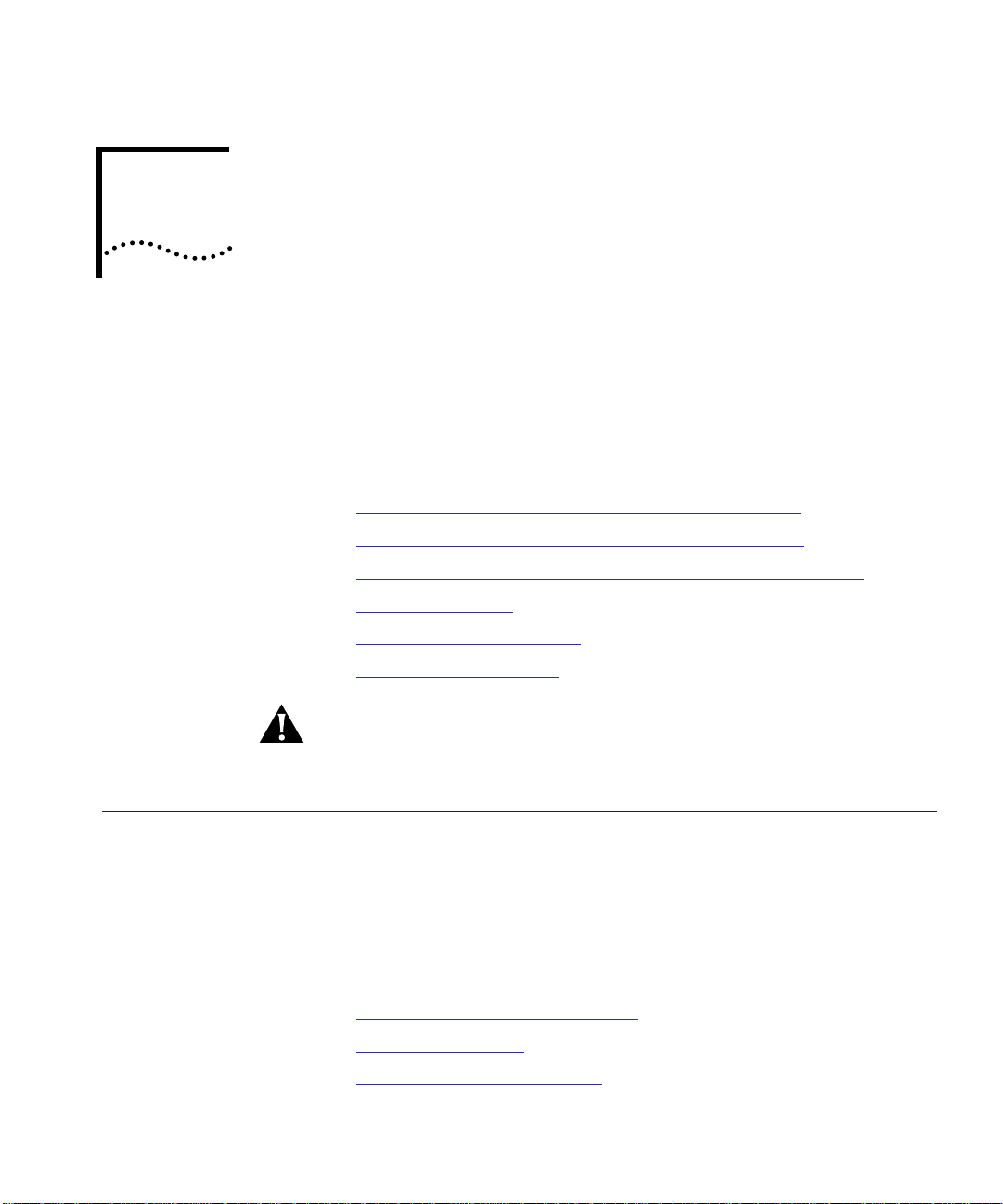
Caution Risk of personal safety, system damage, or loss
of data
Warning Risk of severe personal injury

4 HOW TO USE THIS GUIDE
Related Documents This section provides information on supporting documentation,
including:
■ 3Com Documents
■ Reference Documents
3Com Documents The following documents provide additional information on 3Com
products:
CoreBuilder 5000 Integrated System Hub Installation and Operation
Guide – Provides information on the installation, operation, and
configuration of the CoreBuilder 5000 Integrated System Hub. This
guide also describes the principal features of the CoreBuilder 5000
Fault-Tolerant Controller Module.
Distributed Management Module User Guide – Provides information
on the CoreBuilder 5000 Distributed Management Module’s operation,
installation, and configuration. This guide also describes the software
commands associated with the Distributed Management Module.
Distributed Management Module Commands Guide – Describes each
management command by providing detailed information on the
command’s format, use, and description.
For a complete list of 3Com documents, contact your 3Com
representative.
Reference Documents The following documents supply related background information:
Case, J., Fedor, M., Scoffstall, M., and J. Davin, The Simple Network
Management Protocol, RFC 1157, University of Tennessee at Knoxville,
Performance Systems International and the MIT Laboratory for
Computer Science, May 1990.
Rose, M., and K. McCloghrie, Structure and Identification of
Management Information for TCP/IP-based Internets, RFC 1155,
Performance Systems International and Hughes LAN Systems, May
1990.

1
INTRODUCTION
This chapter describes the 3Com CoreBuilder™ 5000 Ethernet 36-Port
10BASE-T Module (Model Number 6136M-TPCL). For more
information on the 3Com
refer to the CoreBuilder 5000 Integrated System Hub Installation and
Operation Guide.
The Ethernet 36-Port 10BASE-T Module requires the Distributed
Management Module (DMM) Version 2.2 or later for full functionality.
This chapter contains the following sections:
■ 36-Port 10BASE-T Module Description
■ 36-Port 10BASE-T Module Features and Benefits
■ Theory of Operation
®
CoreBuilder 5000 Integrated System Hub,

1-2 CHAPTER 1: INTRODUCTION
36-Port 10BASE-T Module Description
36-Port 10BASE-T Module Features and Benefits
The 36-Port 10BASE-T Module is a connector-switching module which:
■ Supports Telco 50-pin connector-based 10BASE-T wiring
■ Enables users to assign a backplane segment at the connector level
of the module
■ Connects up to 36 devices (PCs, terminals, printers, modems) to
the 3Com CoreBuilder 5000 Integrated System Hub
■ Provides 36 10BASE-T-compliant ports using 25-pair 10BASE-T cables
or 12-leg hydra cables
The CoreBuilder 5000 Ethernet 36-Port 10BASE-T Module provides the
following features:
■ Checks driver and receiver integrity using Remote Diagnostics Mode.
■ Supports security through the CoreBuilder 5000 Private Line Card
(PLC). The PLC provides continuous eavesdropping and intrusion
protection without affecting network performance.
■ Allows you to connect up to two CoreBuilder 5000 Network
Monitor Cards for network management.
■ Allows you to install or remove the module without having to power
down the hub.
■ Supports scalable network management architecture which enables
you to gather Ethernet and Remote Network Monitoring (RMON)
network statistics for any of the CoreBuilder 5000 backplane
segments.
Each module supports two daughter cards including a Network
Monitor Card (NMC) for in-depth monitoring of the network or a
Private Line Card for private Ethernet conversations.
■ Provides easy configuration using the CoreBuilder 5000 Manager.
■ Supports three 12-port Telco 50-pin connectors which you can
switch (per connector) to any of the eight CoreBuilder 5000 hub
backplane channels or eight extended segments in any combination
of eight.
■ Provides per-connector switching to all eight of the
CoreBuilder 5000 hub backplane segments and eight isolated
segments.

36-Port 10BASE-T Module Features and Benefits 1-3
■ Provides IEEE Repeater statistics gathering for monitoring of the
CoreBuilder 5000 hub’s security and network management
architecture.
■ Offers high port density at a low cost per port.
■ Supports up to 100 meters on 10BASE-T-compliant unshielded
twisted pair (UTP) wiring as well as shielded twisted pair (STP)
wiring.
■ Provides connector-switching connectivity for STP and UTP 10BASE-T
networks.
■ Maintains inventory information for the 36-Port 10BASE-T Module in
non-volatile RAM (NVRAM). Information includes the module serial
number, power requirements, power class settings (for example,
powerup priority), and date of manufacture and a user note pad for
entering installation-specific information.
■ Supports CoreBuilder 5000 hub power management architecture
which enables administrators to prioritize the allocation of power to
modules.
In addition, the 36-Port 10BASE-T Module supports Repeater
Management Information Base (MIB) statistics without the need for a
network monitor card.
1-4 CHAPTER 1: INTRODUCTION
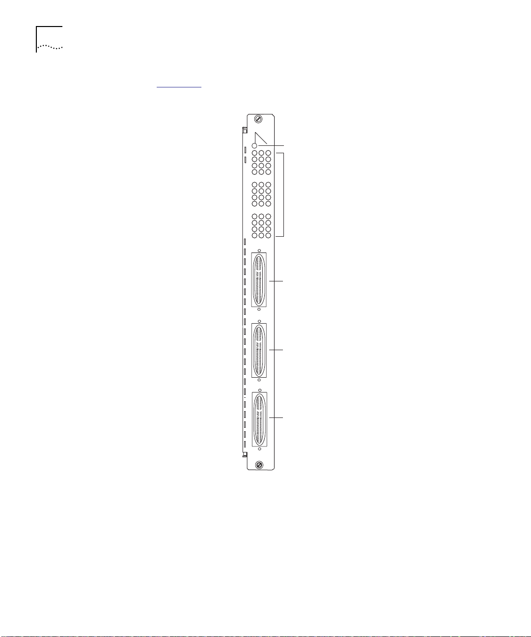
Figure 1-1 illustrates the CoreBuilder 5000 36-Port 10BASE-T Module.
MODULE
STATUS
1
4
7
10
13
16
19
22
25
28
31
34
Module Status LED
Bi-color Status/Activity
Status LEDs
1X-12X
50-pin connector
(ports 1 to 12)
13X-24X
50-pin connector
(ports 13 to 24)
25X-36X
50-pin connector
(ports 25 to 36)
6136M-TPCL
Figure 1-1 CoreBuilder 5000 Ethernet 36-Port 10-BASE-T Module Faceplate
Theory of Operation 1-5
Theory of Operation
Sample Module
Application
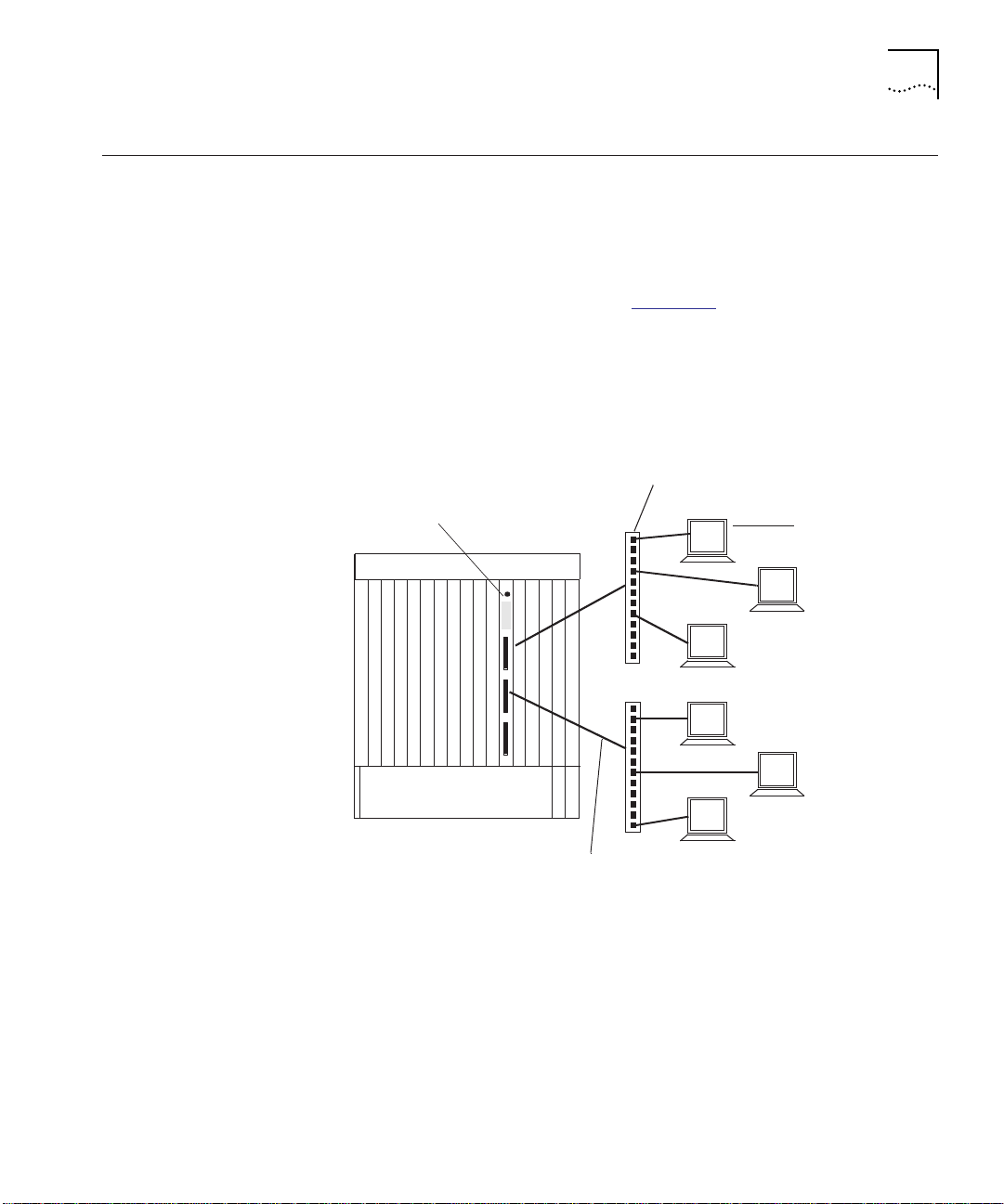
The 36-Port 10BASE-T Module is a connector-switching Ethernet
module that enables administrators to connect up to 36 network
devices to the module using a patch panel or punch-down block for
each Telco 50-pin connector.
You can attach the workstations in Figure 1-2
to the 36-Port 10BASE-T
Module using a patch panel or punch-down block that is directly
connected to the Telco 50-pin connectors on the 36-Port 10BASE-T
Module. Each Telco 50-pin connector provides 12 twisted pair ports
that enable you to connect up to 12 workstations (per connector) to
the 36-Port 10BASE-T Module.
36-Port 10BASE -T
Module
CoreBuilder 5000 Integrated System Hub
Patch
Workstation
Tel co-to-RJ45 connections
Figure 1-2 Sample 36-Port 10BASE-T Module Application

DESIGNING AND EXPANDING THE
2
NETWORK
This chapter describes how to configure networks that use the
CoreBuilder
Ethernet 36-Port 10BASE-T Module.
This chapter contains the following sections:
■ Understanding General Network Configuration Rules
■ Configuring Fiber Backbone, Twisted Pair to-the-Desk
■ Configuring Twisted Pair Backbone, Twisted Pair to-the-Desk
■ Using Patch Panels
■ Using Module Workgroups
■ Setting Redundant Links
CAUTION: To ensure proper operation, install all equipment using only
approved cables. Refer to Appendix A
on twisted pair connector and cable requirements.
™
5000 Integrated System Hub and the CoreBuilder 5000
, Specifications, for information
Understanding General Network Configuration Rules
This section describes general rules for configuring an Ethernet network
using fiber as the backbone medium, and twisted pair as the horizontal
medium (connection to printers, computers). It also provides rules to
ensure that your network configuration conforms to distance limitations
imposed by Ethernet and networking equipment.
The following topics are discussed:
■ Before Configuring Your Network
■ Basic Network Rules
■ LAN Equivalent Requirements

2-2 CHAPTER 2: DESIGNING AND EXPANDING THE NETWORK
Before Configuring
Before configuring your network, consider your:
Your Network
■ Network size from end-to-end:
■ 100 meters
■ 1000 meters
■ 4000 meters
■ Greater than 4000 meters
■ Plans for expansion. Once the network expands beyond a certain
size, you may need to add an Ethernet switch or an additional
internetworking device.
Basic Network Rules Table 2-1
■ Seven basic network rules to keep in mind when you construct
your network
■ 3Com
For hardware-specific information on the Ethernet 36-Port 10BASE-T
Module, refer to Appendix A
Table 2-1 Seven Basic Network Rules
lists:
®
Corporation’s recommendations for these rules
, Specifications.
Rule Definition Recommendations/Notes
1 If possible, use 10BASE-FB
as the backbone medium.
Use 62.5 micron cable to conform with
IEEE 10BASE-F and ANSI FDDI standards.
Use ST-type connectors.
2 Wire the backbone in a star
topology for proper fault
isolation.
Make sure to lay extra fiber cables. The
extra cost is small and you need them as
your network grows.
The star topology conforms to Ethernet
and FDDI wiring. Ensure that you run at
least two FDDI fiber strands to each
backbone connection.

Understanding General Network Configuration Rules 2-3
Table 2-1 Seven Basic Network Rules (continued)
Rule Definition Recommendations/Notes
3 The maximum fiber Ethernet
network diameter is
4200 meters of fiber cable.
4 Certain LAN devices on the
network shrink the
maximum Fiber Ethernet
network diameter to less
than 4200 meters.
5 Assume that 1 meter of
coaxial or twisted pair cable
is equal to 1 meter of fiber
cable.
6 The fiber link distances must
not exceed the limits
imposed by the optical
power budget.
7 When in doubt, use a switch
or bridge.
4200 meters is the maximum distance
between any two transceivers on the
network.
4200 meters does not include the
transceiver cable (that is, drop or patch
cable) that connects a device with an
external transceiver. Transceiver cables
can extend up to 50 meters. Thus, total
network diameter can be as much as
4300 meters (4200 m + 2 * 50 m)
between any two nodes.
Many LAN products delay the signal that
travels through them. This is known as
equivalent distance. Each microsecond
delay:
Reduces the maximum link distance
Shrinks the network diameter by
approximately 200 meters of fiber
cable
Table 2-2
3Com products.
A conservative rule. For example, the
actual equivalence is about 1.1 meters of
coaxial for each meter of fiber. For
simplicity, assume 1 meter.
For 62.5 micron cable, you can utilize up
to 4000 meters point-to-point using
CoreBuilder 5000 or ONline Fiber
Modules. If you have poor quality cable or
cross several patch panels, you may have
to sacrifice some distance in cable length.
Some older Ethernet fiber optic products
are less powerful than CoreBuilder 5000
Fiber Module optics. If connecting to an
Ethernet fiber optic product, remember
that the least powerful device determines
the maximum point-to-point distance.
If you are not certain if you have
exceeded allowable network distances,
use a bridge to extend the network.
lists equivalent distances for

2-4 CHAPTER 2: DESIGNING AND EXPANDING THE NETWORK
LAN Equivalent
Requirements
LAN equivalence is the sum of the incoming and outgoing module port
signals. When you configure your network, consider that each installed
product reduces the network diameter.
Table 2-2
lists the LAN product equivalent distances required for each
LAN product.
Table 2-2 LAN Product Equivalent Distances
Equivalent
LAN Product
CoreBuilder 5000 and ONline Ethernet 10BASE-T Modules 585
Incoming signal to TP port 420
Outgoing signal from TP port 165
CoreBuilder 5000 and ONline Ethernet 10BASE-FB Modules 190
Incoming signal to fiber port 140
Outgoing signal from fiber port 50
ONline Ethernet FOIRL Modules 560
Incoming signal to fiber port 330
Outgoing signal from fiber port 230
CoreBuilder 5000 and ONline Ethernet Transceiver Modules 0
10BASE-FB Star Coupler (8 or 14 port) 180
CoreBuilder 5000 and ONline Ethernet BNC Modules 900
Incoming signal to BNC port 450
Outgoing signal from BNC port 450
CoreBuilder 5000 and ONline Ethernet Repeater Modules 800
Incoming signal to AUI port 600
Outgoing signal from AUI port 200
IEEE Repeater 800
Distance (meters)

Configuring Fiber Backbone, Twisted Pair to-the-Desk 2-5
Configuring Fiber
Backbone, Twisted
Pair to-the-Desk
Fiber Backbone
Configuration Rules
This section describes:
■ Fiber Backbone Configuration Rules
■ Fiber Backbone, Twisted Pair to-the-Desk Configuration Example
■ Verifying Fiber Backbone Configuration
When you configure a network with unshielded twisted pair cabling to
the desk and fiber for the backbone, the following rules apply:
■ Add a bridge if you will exceed 4 full repeater hops.
■ If traffic travels into a port on any repeater-based module and
out the backplane, then the module counts as a ½-repeater hop.
■ If traffic travels into the module through one port and out
another port on the same or a different module, then the
module counts as 1 full repeater hop.
■ The equivalent fiber distance for the 3Com Ethernet 10BASE-FB
Modules (see Table 2-2
■ 140 meters for signals that enter a 10BASE-FB Module port at
) is:
the front panel.
■ 50 meters for signals that internally enter a 10BASE-FB Module
through the CoreBuilder 5000 hub backplane.
■ The equivalent fiber distance for the Ethernet 36-Port 10BASE-T
Modules (see Table 2-2
■ 420 meters for signals that enter the Ethernet 36-Port 10BASE-T
) is:
Module port at the front panel.
■ 165 meters for signals that internally enter an Ethernet 36-Port
10BASE-T Module through the CoreBuilder 5000 hub backplane.
For each pair of Ethernet 36-Port 10BASE-T Modules that a signal
travels through, deduct a fiber equivalent distance of 585 meters
(420 m + 165 m = 585 m) from the overall allowable network
diameter. You must also deduct fiber equivalent distance if a signal
enters the Ethernet 36-Port 10BASE-T Module through one port and
exits another port of the same Ethernet 36-Port 10BASE-T Module.
The fiber equivalent distance counts as 585 meters of fiber equivalent
distance and as a full repeater hop.
2-6 CHAPTER 2: DESIGNING AND EXPANDING THE NETWORK
Fiber Backbone,
Twisted Pair
to-the-Desk
Configuration
Example
Fiber
backbone
1000 m
The sample configuration shown in Figure 2-1 uses 10BASE-T modules
to connect to the transceivers A and B. Refer to the next section for a
detailed explanation of configuration distances.
The 24-gauge unshielded twisted pair cable is used to connect
10BASE-T Transceivers to the Ethernet 36-Port 10BASE-T Modules in
the hubs.
1
2
4
3
6
5
8
7
10
9
1
2
3
4
5
6
7
8
9
10
1
2
4
3
6
5
8
7
10
9
1
2
3
4
5
6
7
8
9
10
500 m
Fiber backbone
1
2
4
3
6
5
8
7
10
9
1
2
3
4
5
6
7
8
9
10
Hub A
Hub B
Hub C
Unshielded twisted pair
100 m
A
Unshielded twisted pair
B
75 m
Unshielded twisted pair
C
Configuration Distance
1. Maximum Diameter:
2. Equivalent Distances:
Hub A:
Hub B:
Hub C:
Total:
3. Amount of cable between
transceivers:
Total:
4. Remaining Distance:
470 m
305 m
190 m
965 m
1000 m
100 m
500 m
75 m
4200 m
1675 m
1560 m
Figure 2-1 Sample Configuration Distance Calculation

Configuring Twisted Pair Backbone, Twisted Pair to-the-Desk 2-7
Verifying Fiber
Backbone
Configuration
To determine if your network configuration is legal:
1 Begin with 4200 meters.
2 Identify the two transceivers (A and B) that are the greatest fiber
equivalent distance apart. In Figure 2-1
, 10BASE-T transceivers A and B
are the farthest apart.
3 Determine the sum of each hub’s equivalent distance using the
distances listed in Table 2-2
. For example, Hub A has an equivalent
distance of 470 m. This total represents the sum of the incoming signal
to the UTP port (420 m) and the outgoing signal from the fiber port
(50 m). Refer to Figure 2-1
for details.
4 Subtract the total equivalent distance of each hub located between
transceivers A and B (965 m) from the maximum network diameter
(4200 m). In this case, the subtotal is 3235 m.
5 Determine the total amount of cable between transceivers A and B
(1675 m) and subtract this number from the subtotal determined in
step 4
(3235 m).
The remaining distance for legal expansion equals 1560 m.
For the configuration shown in Figure 2-1
to function properly, the fiber
equivalent distance between Transceiver A and Transceiver B must be
less than 4200 meters. As a result of the calculation above,
1560 meters remain for expansion.
Configuring
Twisted Pair
Backbone, Twisted
Pair to-the-Desk
This section describes:
■ Twisted Pair Backbone Configuration Rules
■ Twisted Pair Backbone, Twisted Pair to-the-Desk Configuration
Example
■ Determining Fiber Equivalent Distance

2-8 CHAPTER 2: DESIGNING AND EXPANDING THE NETWORK
Twisted Pair
Backbone
Configuration Rules
Twisted Pair
Backbone, Twisted
Pair to-the-Desk
Configuration
Example
When you configure a network with twisted pair cabling to the desk
and twisted pair for the backbone, the following rule applies:
■ Add a bridge if you have more than eight 36-Port modules serially
connected. Each bridge creates a subnetwork. Each subnetwork can
have its own 4200 meter network diameter.
■ If traffic travels into a port on any repeater-based module and
out the backplane, then the module counts as a ½-repeater hop.
■ If traffic travels into the module through one port and out
another port on the same or a different module, then the
module counts as 1 full repeater hop.
Figure 2-2
illustrates a twisted pair network using 24-gauge cable.
B
100 m
A
100 m
100 m
C
100 m
Figure 2-2 Twisted Pair Network
D
50 m

Using Patch Panels 2-9
Determining Fiber
Equivalent Distance
Although there is no fiber in the configuration illustrated in Figure 2-2,
you can calculate the fiber equivalent distance as follows:
1 Total amount of cable between workstations:
100 m + 100 m + 100 m + 100 m + 50 m = 450 m.
2 Total equivalent distance of the Ethernet 36-Port 10BASE-T Modules:
Each hub has an equivalent distance of (420 m + 165 m) or 585 m
Four hubs with a total equivalent distance of (585 m * 4) or 2340 m
exist.
3 Total equivalent distance: 450 m + 2340 m = 2790 m.
1
Incoming signal to the UTP port on each hub = 420 m. Outgoing
signal from the UTP port on each hub = 165 m. Refer to Table 2-2
for more information on LAN product equivalent distances.
Although the twisted pair network example in Figure 2-2
only uses
Ethernet 36-Port 10BASE-T Modules, it is also possible to use other
10BASE-T Modules.
Because the total equivalent distance (2790 meters) is less than
4200 meters, Figure 2-2
illustrates a legitimate configuration.
1.
Using Patch Panels Patch panels make cable management easier by organizing the cables
used in a rack-installed hub. However, patch panels weaken signals that
pass through them, thereby reducing achievable link distances.
3Com assumes the use of one patch panel in the 100 meter link
distance calculations specified in this user guide. Each additional patch
panel in the link reduces the 100 meter link distance by approximately
10 meters.
In the example shown in Figure 2-2
■ If you use two patch panels to connect the upper right PC and the
upper right hub, you must shorten the link distance of 100 meters
to 90 meters. This is because the maximum allowable link distance
on 24-gauge wire (using 10BASE-T signaling with two intervening
patch panels) is 100 meters minus approximately 10 meters.
, the following conditions exist:

2-10 CHAPTER 2: DESIGNING AND EXPANDING THE NETWORK
■ A patch panel installed between the lower right PC and the lower
left hub does not affect the link because the patch panel is only 50
meters away. Patch panels only affect lengths greater than 90
meters.
Using Module Workgroups
Workgroup
Definition
When you set up an Ethernet 36-Port 10BASE-T Module as a fully
configured workgroup module, the resultant logical network
configuration supports up to three workgroups (isolated networks) per
module. Because a managed CoreBuilder 5000 hub may contain as
many as 16 Ethernet 36-Port 10BASE-T modules, it is possible to
configure your hub with a maximum of 48 workgroups.
This section describes:
■ Workgroup Definition
■ Dividing the Network into Workgroups
Workgroups are individual groups set up to divide your network layout
into smaller isolated networks.
Workgroups:
■ Provide administrators with more flexibility in organizing their
network.
■ Decrease the amount of traffic on the backplane segments of the
hubs in which the workgroups reside.
By creating module workgroup networks instead of separate backplane
segment networks, you can configure a maximum of 128 workgroups
per hub using little or no backplane traffic.
Although the Ethernet 36-Port 10BASE-T Module has access to eight
backplane and eight isolated segments, the module only supports
per-connector switching to three segments simultaneously.

Using Module Workgroups 2-11
Dividing the Network
into Workgroups
Dividing the Network
into Workgroups
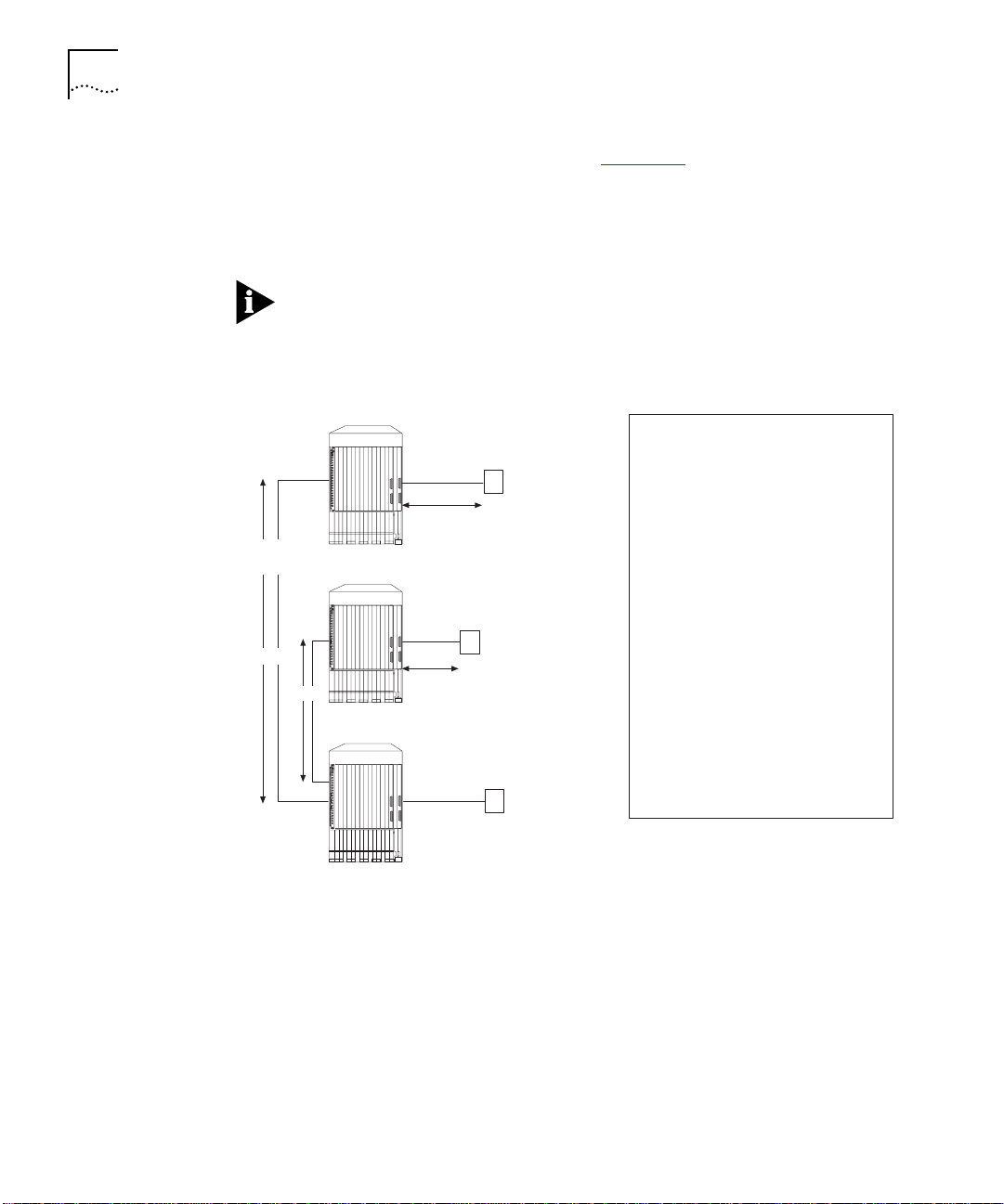
The following example shows how workgroups help administrators to
efficiently organize users in their network.
A network administrator plans to reorganize the development and
support organizations in the company by dividing each department
within those organizations into separate workgroups. Currently, each
organization is connected to separate backplane segments (Figure 2-3
.
Backplane Segment 6
Backplane Segment 5
Backplane Segment 4
Hub C
Engineering
Technical
Support
Development
Organizatio n
Marketing
Technical
Publication s
Support
Organization
).
Figure 2-3 Typical Corporate Organizational Structure

2-12 CHAPTER 2: DESIGNING AND EXPANDING THE NETWORK
To divide the sample network into workgroups, the network
administrator works as follows:
1 After analyzing departmental needs, the network administrator
decides to:
■ Create separate workgroups for each department within the two
organizations
■ Connect the workgroups to each other through an internal
bridge
Table 2-3
describes the reorganization of each department.
Table 2-3 Sample Network Reorganization
10BASE-T
Department
Engineering
Department
Technical
Support
Marketing 36-Port 1 WG4 1 to 12
Technical
Publications
2 As Ta b le 2 - 3
Module Type
36-Port 3 WG2 13 to 24
36-Port 6 WG3 13 to 24
36-Port 8 WG1 25 to 36
indicates, the network administrator assigns four
Module Slot
Number
Workgroup
Number
organizations within the company to separate workgroup numbers
(WG1 to WG4). The workgroups can:
■ Share resources
■ Communicate with each other without using the hub backplane
Ports
Used

Using Module Workgroups 2-13
Figure 2-4 illustrates each workgroup configuration.
HUB C
BR
Slot 4
WG4
KEY
WGx
1
to
12
WG2
13
to
24
25
to
36
Slot 1 Slot 3 Slot 6 Slot 8
= Module Workgroup Network (where x is the workgroup numbe r)
= Internal Bridg e
BR
= Port allocated to inter na l brid ge
1
= Workgroup
to
x
12
13
24
25
36
1
to
WG3
to
to
12
13
24
25
36
1
to
to
WG1
to
1
to
12
13
to
24
25
to
36
Figure 2-4 36-Port 10BASE-T Module Workgroup Port Allocation
To enable all of the workgroups to communicate with other networks,
the network administrator must connect at least one port per
workgroup to the bridge (see Figure 2-4
).
By dividing the network into workgroups, you:
■ Increase the available number of backplane resources
■ Decrease overall backplane traffic

2-14 CHAPTER 2: DESIGNING AND EXPANDING THE NETWORK
3 In Figure 2-4, the network administrator configures four separate
workgroups (WG1 to WG4) and connects the workgroups to each
other using an internal bridge module (such as the CoreBuilder 5000
Multiprotocol Switching Module).
The advantages of the configuration in Figure 2-4
■ Networks configured as module workgroups provide greater
include:
network capacity (8 backplane networks and 48 module
workgroup networks)
■ Network configuration is more flexible because administrators are
not limited to 8 backplane networks only
■ Less backplane traffic because communication between each
department is isolated from the hub backplane
If the network administrator had configured each of the workgroups on
separate backplane segment networks instead of separate module
workgroup networks, he or she would need to isolate 3 of the hub’s 8
backplane segments from the rest of the network.
By configuring the departments as module workgroup networks instead
of separate backplane segment networks, the network administrator
can configure a maximum of 48 workgroups per hub using little or no
backplane traffic.

Setting Redundant Links 2-15
Setting Redundant Links
When you set up a redundant twisted pair link between ports on
CoreBuilder 5000 Integrated System Hubs, the resultant configuration
prevents a network failure. Figure 2-5
shows two examples of a
redundant configuration.
1
1
1
2
2
3
3
4
4
5
5
6
6
7
7
8
8
9
9
10
10
11
11
12
12
13
13
14
14
15
15
16
16
17
17
18
18
19
19
20
20
21
21
22
22
23
23
24
24
1
1
2
2
3
3
4
4
1
1
2
2
3
3
1
2
2
3
3
4
4
5
5
6
6
7
7
8
8
9
9
10
10
11
11
12
12
13
13
14
14
15
15
16
16
17
17
18
18
19
19
20
20
21
21
22
22
23
23
24
24
1
1
2
2
3
3
4
4
1
1
2
2
3
3
Redundancy set up between two
ports on the same module.
Redundancy set up between two
ports on different modules.
Figure 2-5 Redundant Twisted Pair Configuration
It is also possible to enable redundancy between ONline modules in a
CoreBuilder 5000 hub.

2-16 CHAPTER 2: DESIGNING AND EXPANDING THE NETWORK
Setting Redundancy
Between Two Ports
on One 36-Port
10BASE-T Module
Setting Redundancy
Between Ports on
Two 36-Port
10BASE-T Modules
To connect two links to two ports on one Ethernet 36-Port 10BASE-T
Module:
1 Issue the SET PORT MODE REDUNDANT network management
command.
2 Specify the primary link port and the backup link port.
For example, if you set up a redundant link using the following
command:
SET POR T 8.5 MODE REDUNDANT 8.7
Port 5 in slot 8 becomes the primary link and port 7 in slot 8 becomes
the backup link.
To connect two links to two ports between two Ethernet 36-Port
10BASE-T Modules:
1 Issue the SET PORT MODE REDUNDANT network management
command.
2 Specify the primary link port and the backup link port.
For example, if you set up a redundant link using the following
command:
SET PORT 12.4 MODE REDUNDANT 8.9
Port 4 in slot 12 becomes the primary link and port 9 in slot 8 becomes
the backup link.
CAUTION: Setting inter-module redundancy on the Ethernet 36-Port
10BASE-T Module is a management module software function.
Consequently, a network loop could occur if the module is set to
redundant mode and it is powered down and then up without a 3Com
network management module in the hub.
Once you configure redundancy:
1 A switchover to the backup link occurs under two conditions:
■ Link failure
■ Port partition

Setting Redundant Links 2-17
2 Once the switchover occurs and the backup link becomes operational,
the system performs a switchover back to the primary link
automatically. The failure or port partition problem is then resolved.
Although you can configure redundancy between two ports on a single
module, you should configure redundancy between two ports on two
different modules. This provides additional protection if, for example,
one of the modules becomes inoperative.
Refer to the CoreBuilder 5000 Distributed Management Module User
Guide for more information on setting redundancy between Ethernet
36-Port 10BASE-T Module ports.


INSTALLING AND OPERATING THE
3
MODULE
This chapter describes the installation of the CoreBuilder™ 5000
Ethernet 36-Port 10BASE-T Module.
A module reference card for the Ethernet 36-Port 10BASE-T Module
(Document Number 17-00630) lists the DIP switch settings, Ethernet
36-Port 10BASE-T Module management commands, LED indicators, and
other module information. Store the card in the CoreBuilder 5000 hub
binder in the Reference Card section.
This chapter contains the following sections:
■ Precautionary Procedures
■ Unpacking Procedures
■ Quick Installation
■ Setting DIP Switches
■ Installing the Module
■ Configuring the Module
■ Showing Module Configurations
■ Connecting Module Daughter Cards
■ Gathering Statistics
■ Monitoring the Front Panel
■ Verifying LED and Network Operation
Read the precautionary procedures before unpacking the module.

3-2 CHAPTER 3: INSTALLING AND OPERATING THE MODULE
Precautionary Procedures
CAUTION: Electrostatic discharge (ESD) can damage static-sensitive
devices on circuit boards.
Follow these precautions when you handle the 36-Port 10BASE-T
Module:
■ Do not remove the board from its antistatic shielding bag until you
are ready to inspect or install it.
■ Handle the board by the faceplate only.
Use one of the following proper grounding techniques when you install
the 36-Port 10BASE-T Module:
■ Use a foot strap and grounded mat or wear a grounded static
discharge wrist strap.
■ Touch the grounded rack or other source of ground just before you
handle the module and I/O cards.
Unpacking Procedures
To unpack the 36-Port 10BASE-T Module:
1 Verify that the 36-Port 10BASE-T Module (Model Number 6136M-TPCL)
is the model you ordered by checking the Model Number listed on the
side of the shipping carton.
Note that the product model number printed on the shipping box
differs from the model number on the product. The model number on
the shipping box contains the prefix ’3C9’.
2 Remove the 36-Port 10BASE-T Module, in its antistatic bag, from the
shipping carton.
3 Remove the module from the antistatic shielding bag and inspect it for
damage.
Always handle the 36-Port 10BASE-T Module by the faceplate, being
careful not to touch the components. If the module appears to be
damaged, return it to the antistatic shielding bag, repack it in the
shipping carton, and contact your local supplier.

Quick Installation 3-3
Keep the shipping carton and antistatic shielding bag in which your
module was shipped for future storage or shipment.
Record the serial number of your 36-Port 10BASE-T Module. The Hub
Planning Chart, located in the CoreBuilder 5000 reference binder, and
the Module Planning Chart supplied with your module are provided for
this purpose.
Quick Installation Table 3-1 outlines the steps for the installation of your module. If you
are familiar with installing CoreBuilder 5000 modules, use this table as
a checklist. Otherwise, consult the remainder of this chapter.
Table 3-1 Quick Installation Checklist
Step Procedure Chapter/Section
1 Verify that your network complies with the
basic rules for network design.
2 Unpack the module. Chapter 3, Unpacking
3 Configure the DIP switch settings. If you
have a network management module
installed in the hub, configure the module
using the management commands
described later in this chapter.
4 Enter the SHOW POWER1 command at the
5 Insert a 36-Port 10BASE-T module into one
6 Establish connections from the 36-Port
7 Verify LED status for normal operation. Chapter 3, Verifying LED
1
Refer to the CoreBuilder 5000 Integrated System Hub Installation and Operation Guide for
command line of the terminal. This
command displays current power
requirements for the hub.
open slot in the hub. Fasten the ejectors
and tighten the faceplate screws.
10BASE-T module to devices using the
appropriate connectors and cabling.
details on hub power requirements.
Chapter 2, Designing and
Expanding the Network
Procedures
Chapter 3, Setting DIP
Switches or Configuring
the Module
Chapter 3, Installing the
Module
Chapter 3, Installing the
Module
Chapter 3, Installing the
Module
and Network Operation
For information about potential problems, consult the troubleshooting
techniques in Chapter 4
.

3-4 CHAPTER 3: INSTALLING AND OPERATING THE MODULE
Setting DIP Switches
If you are using a management module and do not plan to use the DIP
configuration command, skip this section and go to the section
Installing the Module
The CoreBuilder 5000 Ethernet 36-Port 10BASE-T Module has an
8-position DIP switch. All of the DIP switch settings on the 36-Port
10BASE-T Module are ignored if an appropriate CoreBuilder 5000
Distributed Network Management Module (DMM Version v2.2 or later,
for example) is already installed in the hub. Use network management
commands, rather than the DIP switches, to configure the module.
This section describes:
■ DIP Switch Features
■ Setting the DIP Switches
■ DIP Switch Definition
DIP Switch Features Use the DIP switch to:
■ Select a network for all ports on the 36-Port 10BASE-T Module
■ Choose the primary module configuration:
■ Non-volatile RAM configuration (software configuration)
in this chapter.
Setting the DIP
Switches
■ DIP segment selection (DIP-specified module configuration)
You cannot assign connectors to different networks using the DIP
switches on the 36-Port 10BASE-T Module. You must use network
management commands.
To set the module to access the DIP switch settings when using a
management module, issue the SET DEVI CE DIP_CONFIGURATION
command from the management module.
If you do not have a CoreBuilder 5000 Distributed Network
Management Module installed in your hub, your hub configuration
defaults to the DIP switch settings on the module.

Setting DIP Switches 3-5
Figure 3-1 shows the DIP switch location on the module.
1
2
3
4
5
6
7
8
DIP switches
234 5678
1
On 1
Off 0
NV
DIP settings
ISOLATE
CH SEL 2
CH SEL 0
CH SEL 1
NOT USED
NOT USED
NOT USED
DIP switch location
Backplane DIN
connector
Figure 3-1 36-Port 10BASE-T Module DIP Switch Location
DIP Switch Definition Each DIP switch function is defined in the section Configuring the
Module later in this chapter.
Table 3-2
■ Switches 1 through 4 enable you to configure all ports to one of the
describes the following DIP switch settings:
backplane segments (Ethernet 1 to Ethernet 8) or as a workgroup
(Isolate_1).
■ Switch 5 enables you to switch between non-volatile RAM
(NVRAM) or DIP-switch controlled configuration.
■ Switches 6, 7, and 8 are not used.

3-6 CHAPTER 3: INSTALLING AND OPERATING THE MODULE
Table 3-2 Network Selection DIP Switch Settings
Network
Selection
Switch Settings
Switch 4 Switch 3 Switch 2 Switch 1
1 (default) Off Off Off Off
2 Off Off Off On
3 Off Off On Off
4 Off Off On On
5 Off On Off Off
6 Off On Off On
7 Off On On Off
8 Off On On On
Isolate_1 On N/A N/A N/A
1
By default, Switch 5 is set to NVRAM. When enabled, settings stored in NVRAM take
precedence over DIP Switch settings 1 through 4.
The DIP switch legend on the module refers to the backplane
connection as the channel selection (CH SEL). The channel setting and
the network setting are the same. Ports set to the same network
communicate with each other. If the switch labeled ISOLATE is ON, it
sets the module to Isolated_1.
1
When the 36-Port 10BASE-T Module is first installed, the hub checks
for configuration settings in the DMM and decides the following:
■ If the hub is managed, the module uses the settings from the DMM.
■ If the hub is unmanaged, then the 36-Port 10BASE-T Module:
■ Checks for configuration settings stored in NVRAM.
■ Checks the DIP switches for configuration information if there are
no configuration settings in NVRAM or DIP Switch 5 is set to
DIP-switch controlled configuration.

Installing the Module 3-7
Installing the Module
You do not need to power off the CoreBuilder 5000 Integrated System
Hub to install
or remove the 36-Port 10BASE-T Module. You can insert
the module while the hub is operating (this is called a hot swap).
To install the 36-Port 10BASE-T Module:
1 Use one of the following proper grounding techniques when you install
the 36-Port 10BASE-T Module:
■ Properly ground yourself prior to handling the 36-Port 10BASE-T
Module.
■ Attach a static wrist guard to yourself or touch a grounded static
mat prior to handling the 36-Port 10BASE-T Module.
2 Configure the 36-Port 10BASE-T Module:
■ If you plan to install the 36-Port 10BASE-T Module in a managed
hub (for example, DMM Version v2.2 or later), go to step 3
to
complete the installation. To configure the appropriate settings,
refer to the section Configuring the Module
■ If you plan to insert the 36-Port 10BASE-T Module in an
later in this chapter.
unmanaged hub, configure the DIP switch settings on the
module to the desired settings (refer to the section Setting DIP
Switches earlier in this chapter) and go to step 4.
3 To determine if the hub has enough power for the new module, from
the DMM command line, enter the SHOW POWER BUDGET command.
Refer to Appendix A, Electrical Specifications
, for details on power
requirements for each of the specified watts ranges.
Refer to the CoreBuilder 5000 Distributed Management Module
Commands Guide for information on the SHOW POWER BUDGET
command.
4 Locate an open slot in the hub. Remove the appropriate number of
blank panels on the hub to expose a slot for the module, if necessary.
5 Insert the module into the board guides at the top and bottom of the
slot and slide it into the hub by pressing firmly at the top and bottom
of the faceplate. Figure 3-2
shows the installation of a
CoreBuilder 5000 module.

3-8 CHAPTER 3: INSTALLING AND OPERATING THE MODULE
Figure 3-2 Installing a CoreBuilder 5000 Module

Installing the Module 3-9
6 Close the 36-Port 10BASE-T Module ejectors (Figure 3-3).
Open ed
eject or
Closed
ejector
Figure 3-3 Opened and Closed Module Ejectors
7 Using your fingers, fasten the spring-loaded screws on the front of the
36-Port 10BASE-T Module faceplate to the hub (do not overtighten).
8 Attach three 180° 50-pin cable connectors to the 50-pin connectors on
the front of the module (see Figure 3-4
), using the small screws
included in the shipping carton. If you are using 90° connectors, refer
to the section Attaching the Tie-Wrap Bracket
later in this chapter.

3-10 CHAPTER 3: INSTALLING AND OPERATING THE MODULE
9 Secure the cables to the module connectors as shown in Figure 3-4.
1
1
2
2
3
3
4
4
5
5
6
6
7
7
8
8
9
9
10
1
0
11
1
1
12
1
2
13
1
3
14
1
4
15
1
5
16
1
6
17
1
7
18
1
8
19
1
9
20
2
0
2
21
1
2
22
2
23
2
3
24
2
4
1
4
7
10
13
16
19
22
25
28
31
34
STATUS
1X-12X
13X-24X
MODULE
1
1
2
2
3
3
4
4
1
1
2
2
3
3
25X-36X
O
180 50-pin cable connectors
50-pin connector
6136M-TPCL
Figure 3-4 50-Pin Connector Cable Connection
10 Attach the other ends of the cables to a 10BASE-T transceiver, patch
panel, or a 10BASE-T adapter card.

Installing the Module 3-11
Attaching the
Tie-Wrap Bracket
This section describes how to attach a tie-wrap bracket to a 36-Port
10BASE-T Module.
You should use 180° connectors with the 36-Port 10-BASE-T Module.
If, however, you currently use 90° cable connectors, use the following
procedure to fasten the tie-wrap bracket to the connector on the
module.
Before You Begin
Before attaching tie wraps to the 36-Port 10BASE-T Module connector,
be sure that the module is equipped with two Tie-Wrap Kits (Part
number 40-0166) that contain:
■ 1 screw
■ 1 anchor
■ 1 kit card
■ 1 bag
■ 3 tie wraps
Perform the procedure below prior to installing the module into the
CoreBuilder 5000 hub.
To attach the tie-wrap bracket:
1 Remove the hex nut from the bottom of the module connector.

3-12 CHAPTER 3: INSTALLING AND OPERATING THE MODULE
2 Attach the tie-wrap bracket to the 36-Port 10BASE-T Module using the
Phillips-head screw provided in the Tie-Wrap Kit (Figure 3-5
Tie-wrap
bracket
Phillips head
screw
Figure 3-5 Attaching the Tie-Wrap Bracket to the 36-Port Module
Top
).
Insert the tie-wrap
through the opening on
the tie-wrap bracket
1
4
7
10
13
16
19
22
25
28
31
34
MODULE
STATUS
1X-12X
13X-24X
25X-36X
6136M-TPCL
3 Insert the tie wrap through the opening on the tie-wrap bracket.
4 Attach the 90° cable connectors to the module connector as shown in
Figure 3-6
.

Installing the Module 3-13
MODULE
STATUS
1
4
7
10
13
16
19
22
25
1
1
2
2
3
3
4
4
5
5
6
6
7
7
8
8
9
9
10
10
11
11
12
12
13
13
14
14
15
15
16
16
17
17
18
18
19
19
20
20
21
21
22
22
23
23
24
24
1
1
2
2
3
3
4
4
1
1
2
2
3
3
28
31
34
1X-12X
13X-24X
50-pin connector
Standoff
25X-36X
50-pin cable connector
6136M-TPCL
Figure 3-6 Attaching Cables With 90° Connectors
5 Wrap the tie-wrap connector strap around the 50-pin cable connector
to secure the cable connector to the module connector.
6 Attach the other ends of the cables to a 10BASE-T transceiver, patch
panel, or a 10BASE-T adapter card.
Ensure that you do not fasten the tie wrap around the 36-Port
10BASE-T Module ejectors shown in Figure 3-3
.

3-14 CHAPTER 3: INSTALLING AND OPERATING THE MODULE
Configuring the Module
Configuration
Overview
This section describes how to configure the module using network
management commands. The following network management
commands are used to configure the 36-Port 10BASE-T Module:
■ Set Port Mode Commands
■ Enable/Disable Link Integrity Command
■ Set Port Alert Filter Command
■ Set Port Auto Polarity Command
■ Network Selection
For additional information on network management commands, refer
to the CoreBuilder 5000 Distributed Management Module Commands
Guide.
The CoreBuilder 5000 Distributed Management Module (DMM)
provides network management for the CoreBuilder 5000 Integrated
System Hub and its modules. Use network management commands,
rather than the DIP switches, to configure the module. All of the DIP
switch settings on the 36-Port 10BASE-T Module are ignored if an
appropriate CoreBuilder 5000 Distributed Network Management
Module (DMM Version v2.2 or later) is already installed in the hub.
If network management is present when you first install the module,
the:
■ Network defaults to isolated mode.
■ Ports are automatically disabled (so that users cannot join the
network undetected by network management).
Therefore, you must enable the ports you want to use and set the
module ports to the appropriate network using management
commands.
Do not manage (get statistics or configure) this module from a slave
management module.

Configuring the Module 3-15
Set Port Mode
Commands
This section describes the following SET PORT MODE commands:
■ Enable/Disable/Shutdown Ports Command
■ Setting Port Redundancy Command
■ Setting Remote Diagnostics Command
Enable/Disable/Shutdown Ports Command
This command allows you to enable, disable, and shutdown each port
on the 36-Port 10BASE-T Module.
When a port is set to:
■ Enable – It transmits to and receives data from the network to
which the port is assigned.
■ Disable – It does not transmit or receive data. (Link integrity is
unaffected.)
■ Shutdown – It turns off link integrity and the transmitter. The port
responds with status OFF at the terminal.
Use the following command to enable, disable, or shutdown a port:
SET PORT {
slot.port
{
slot
} MODE {disable}
.all} {enable}
{shu tdow n}
Setting Port Redundancy Command
This command allows you to set redundancy between ports. When
you set two ports redundant to each other, the secondary port takes
over if the primary port fails.
Use the following command to set redundancy between ports:
SET PORT {
slot .por t
} MODE {redundant} {
{non-redundant}
slot.port
}
For an example of port redundancy, refer to the section Setting
Redundant Links in Chapter 2.

3-16 CHAPTER 3: INSTALLING AND OPERATING THE MODULE
Setting Remote Diagnostics Command
This command allows the 36-Port 10BASE-T Module to detect certain
unusual failure conditions when used with a 3Com Fault-Tolerant
10BASE-T Transceiver (including disruption of single wires in the twisted
pairs). The Fault-Tolerant 10Base-T Transceiver Installation Guide
describes this feature in detail.
Use the following command to set remote diagnostics:
Enable/Disable Link
Integrity Command
SET PORT {
slot.port
} MO DE {RE MO TE _DIA GN OSTIC S} [
{NON_REMOTE_DIAGNOSTICS}
slot .port
]
In the command above, the last variable, slot.port, is optional. When
Remote Diagnostic mode is enabled, it is referred to as a buddy port.
This command allows you to enable or disable link integrity for all ports
on the 36-Port 10BASE-T Module in networks that comply with the
10BASE-T standard.
You should set link integrity to:
■ Disable – When connecting to older equipment that does not
comply with the 10BASE-T standard.
■ Enable – For all ports on your 10BASE-T Module. You must enable
link integrity at one end of the connection.
Use the following command to enable or disable link integrity for each
port on the module:
SET PORT {
slot.port
{
slot.
all} {disabl e}
} LINK_ INTE GRIT Y {e nable }
Set Port Alert Filter
Command
This command allows you to override the PORT ALERT FILTER feature
on a port-by-port basis. The PORT ALERT FILTER feature enables or
disables the DMM delivery of port up and port down traps. You can
use this command to continue to monitor port status on crucial ports
(file servers, for example), while alerts from other ports are disabled.
Configure Alert Filter to:
■ Enable – To use the PORT ALERT filtering feature.

Configuring the Module 3-17
■ Disable – To cause all port up and port down alerts to display.
Use the following command to enable or disable the port up and port
down alerts for a port:
Set Port Auto
Polarity Command
SET PORT {
slot.port
{
slot.
all} {enable}
} ALERT _F ILTE R {d isabl e}
The following output is an example of the SET PORT ALERT_FILTER
command issued for port 1 of a 36-port module in slot 1:
CB50 00> set po rt 1.1 aler t_filter di sable
Port 01 .01 Alert Filter set to DISABLE
Set the SET ALERT PORT_UP_DOWN FILTER command before you use
the SET PORT ALERT_FILTER command.
For more information on this command, refer to the CoreBuilder 5000
Distributed Management Module Commands Guide.
This command enables the 36-Port 10BASE-T Module to automatically
switch the polarity of twisted pair cabling. If, for instance, you
erroneously reverse the polarity of some twisted pair cabling while
assembling it, Auto Polarity enables you to automatically detect this
problem and reverse the polarity.
Use the following command to enable or disable auto polarity for
a port:
SET PORT {
slot.port
{
slot.
all} {ena ble}
} AUTO_POLARITY {disable}
Network Selection This command provides connector-level configuration flexibility using
the unique architecture of the CoreBuilder 5000 Integrated System
Hub. You can assign connectors to any of eight backplane segments or
any of the eight isolated segments. Refer to the CoreBuilder 5000
Integrated System Hub Installation and Operation Guide, Chapter 1, for
a complete discussion of the CoreBuilder 5000 hub architecture.
The DIP switch settings on the module refer to the backplane
connection as the channel selection (CH SEL). The channel setting and
the network setting are the same.

3-18 CHAPTER 3: INSTALLING AND OPERATING THE MODULE
Assigning Connectors on the Module to a Network
Use the DIP switch settings on the 36-Port 10BASE-T Module to assign
connectors on the module to network one through eight or to an
extended segment. Network management, however, lets you assign
one or more connectors to a network.
Use the following command to assign one or more connectors to a
network:
SETMODULE{
CONNEC TOR _2_N ET WO RK {isola te d_1.. _8 }
CONN ECTOR _3 _NET WO RK
slot.subsl ot
} CONNECTOR_1_NETWORk {ethernet_1.._8}
Use this command to assign users to backplane segments or isolated
segments (workgroups). For instance, to create a module segment
workgroup, you must assign all of the users in the workgroup to one
isolated network (for example, ISOLATED_1).
For more information on workgroups, refer to Chapter 2, the section
titled Using Module Workgroups
.
Assigning a Monitor Card to a Network
If you have a CoreBuilder 5000 Ethernet Network Monitor Card or
Private Line Card installed on this module, network management also
enables you to assign the monitor card to a network. The
CoreBuilder 5000 36-Port 10BASE-T Module supports up to two
daughter cards. You can assign the daughter cards to any of the eight
backplane segments, whether or not any of the ports are assigned to
that segment. You can also assign daughter cards to an isolated
segment.
Use the following command to assign a daughter card to a network:
SET MO DUL E {
slot.subslot
} NE TWORK {ether net_ 1.. ._8}
{isola te d_1. .. _8}
The CoreBuilder 5000 Ethernet Network Monitor Card is configured as
subslot 2 or 3 on the 36-Port 10BASE-T Module. The default, subslot 1,
refers to the 36-Port 10BASE-T Module.

Showing Module Configurations 3-19
Showing Module Configurations
Show Module
Command
CB50 00> show m odule 10.1 verbose
Slot Module Version Network General Informat ion
----- ----- --------- ---- ---- --- ---------------- --------- -------- --
10.01 6 136M-TPCL 1.00 PER_C ONNECTOR
6136M-TPCL: CB5000 Et hernet Te lco 10BAS E-T Module
Boot Versio n: 1.00
Network Dip Setting: I SOLATED_1
Network for Connector 01: ETHER NET_1
Network for Connector 02: ETHER NET_2
Network for Connector 03: ETHER NET_3
Non-Volatil e DIP Sett ing: ENABL ED
You can display status information about the 36-Port 10BASE-T Module
using the following network management commands:
■ SHOW MODULE
■ SHOW PORT
This command enables users to display both brief and verbose
information about a particular module.
Use the following command to display module information:
SHOW MODULE {
slot.subslot
{
slot.
all} {no_ verbo se }
} {verbose}
The following output is an example of the SHOW MODULE VERBOSE
command issued for a 36-Port 10BASE-T Module installed in slot 10:
Show Port Command This command enables users to display brief and verbose information
on both individual ports and all ports collectively.
Use the following command to display port information:
SHOW PORT {
slot.port
{
slot.
all} {no_verbose}
} {ve rb os e}

3-20 CHAPTER 3: INSTALLING AND OPERATING THE MODULE
The following output is an example of the SHOW PORT ALL VERBOSE
command issued for a 36-Port 10BASE-T Module installed in slot 10:
CB50 00> show p ort 10.all verbose
Port Di splay for Module 6136M -TPCL:
Port Mo de Status Network General In formatio n
----- - ------- -- ------------ ------- -------- - ------------------ ---
10.01 E NABLED OK AY ETHER NET_1
Alert F ilter: ENABLED
Port Co nnector: TELCO
Link In tegrity: ENABLED
Auto Po larity: ENABLED
10.02 D ISABLED LI NK FAILUR E E THERNET_1
Alert F ilter: ENABLED
Port Co nnector: TELCO
Link In tegrity: ENABLED
Auto Po larity: DISABLE D
Port Mo de Status Network General In formatio n
----- ----- --- ------ -------- - ---------------- ----------- -------- -
10.03 D ISABLED LI NK FAILUR E E THERNET_1
Alert F ilter: ENABLED
Port Co nnector: TELCO
Link In tegrity: ENABLED
Auto Po larity: DISABLE D

Connecting Module Daughter Cards 3-21
Connecting Module Daughter Cards
This section describes the location for connecting an Ethernet Network
Monitor Card or a Private Line Card (PLC) to the 36-Port 10BASE-T
Module. The 36-Port 10BASE-T Module supports up to two daughter
cards. This capability gives you greater flexibility in both creating
workgroups and configuring modules.
To monitor Ethernet and RMON statistics on your 36-Port 10BASE-T
Module you must attach a CoreBuilder 5000 Ethernet Network Monitor
Card (ENMC). Attach the ENMC to the network you want to monitor.
The ENMC allows you to individually select and monitor each backplane
segment on your CoreBuilder 5000 hub. You can assign this card to
any of the eight isolated or backplane segments.
To provide continuous eavesdropping and intrusion protection without
affecting network performance you must attach a CoreBuilder 5000
Private Line Card. Up to two Private Line Cards can be connected to
the 36-Port 10BASE-T Module.
Use the same procedure for installing Ethernet Network Monitor Cards
(NMC) when you install Ethernet Private Line Cards. The PLC is attached
in the same subslot location as the NMC.
For details on installing network monitor cards, refer to the 3Com
documentation that accompanies the CoreBuilder 5000 Ethernet
Network Monitor Card.

3-22 CHAPTER 3: INSTALLING AND OPERATING THE MODULE
Figure 3-7 provides a component side view of the 36-Port 10BASE-T
Module with the Network Monitor Card orientation on the module.
Standoffs
Screw
DIP switch
ON
SW1
sw2
sw3
sw4
sw5
sw6
sw7
sw8
Subslot 3
50-pin Telco
connectors
Subslot 2
DB connectors
Figure 3-7 Attaching the CoreBuilder 5000 Ethernet Monitor Card
Monitor card
Backplane connector

Gathering Statistics 3-23
Gathering Statistics This section describes the following:
■ Gathering Statistics
■ Monitoring the Front Panel
Gathering Statistics The 36-Port 10BASE-T Module gathers the following statistics:
■ Repeater Statistics
■ Ethernet and RMON Statistics
Repeater Statistics
The 36-Port 10BASE-T Module gathers repeater statistics for each port
(for example, collision, partition, late collision, data rate mismatch, and
short event statistics). This module gathers repeater statistics without
the use of a Network Monitor Card.
The repeater statistics that are available include:
■ Network – Network statistics are presented by gathering events
from all ports on the 36-Port 10BASE-T Module and other modules
in the hub whose ports are on the same network and summarizing
them.
■ Module – Module statistics summarize the events on all ports on a
specified module on the same network.
■ Port – Per-port statistics are a count of events from traffic entering
the module.
Ethernet and RMON Statistics
Unlike repeater statistics, Ethernet and RMON statistics (for example,
single collision frames, internal MAC transmit errors, frame too long)
are only available when a Network Monitor Card is defined. Use the
MONITOR and SHOW COUNTER commands to view statistics. For an
explanation on how to view these statistics, refer to the next section,
Monitoring the Network.

3-24 CHAPTER 3: INSTALLING AND OPERATING THE MODULE
It is possible to install the monitor card on either the 36-Port 10BASE-T
Module or the Distributed Management Module for Ethernet
(DMM-EC). For more information on the DMM, refer to the
CoreBuilder 5000 Distributed Management Module User Guide.
The CoreBuilder 5000 Ethernet Network Monitor Card does not provide
per-port statistics for ONline modules when it is installed on the 36-Port
10BASE-T Module. If, however, the card is installed on the DMM-EC, it
is possible to collect per-port statistics for ONline modules.
Monitoring Network
Statistics
The 36-Port 10BASE-T Module supports two daughter cards. You can
assign these cards to any of the eight networks (isolated or backplane
segments). The ability to support two cards provides greater flexibility in
both creating workgroups and configuring modules.
Once the monitor card is attached to the 36-Port 10BASE-T Module,
you can monitor statistics using the following commands:
■ MONITOR
■ SHOW COUNTER
Monitor Command
This command allows you to monitor each network (individually) by
specifying the backplane or isolated segment to which the ports are
configured.
Use the following command to monitor a network:
MONITOR {mm:ss} {ETHERNET} {ethernet_1..._8}
{REPEATER} {isolated_1..._8}
{RMON}
The system-specified range of time allotted for monitoring the network
is 00 to 30 minutes (mm) and 05 to 59 seconds (ss). Use these ranges
when specifying a length of time to monitor your network.

Gathering Statistics 3-25
The following output is an example of the MONITOR ETHERNET
command for a 36-Port 10BASE-T Module assigned to network
Ethernet_1. This example monitors Ethernet_1 every 10 seconds:
CB50 00> monito r 00:10 et hernet et hernet_1
Ethernet Statistics for ETHERNET_1
--------------------------------------------------------------------Cumulative Last Time Inte rval
------ --------- -------- -------------------- -------- --------- ---------
FCS Errors 0 0
SQE Test Errors 0 0
Alignment Errors 0 0
Carrie r Sense Err ors 0 0
Frame Too Lo ng 0 0
Deferr ed Transmi ssions 0 0
Late Co llisions 0 0
Excess ive Collis ions 0 0
Single Coll ision Fram es 0 0
Multip le Collisi on Frames 0 0
Intern al MAC Rece ive Errors 0 0
Intern al MAC Tran smit Erro rs 0 0
Display wil l refresh e very 10 seconds.
Press C TRL-C to exit.
Show Counter Command
This command provides you with detailed information on Ethernet and
RMON statistics. Ethernet and RMON statistics-gathering requires a
Network Monitor Card.
Use the following command to gather Ethernet and RMON statistics:
SHOW COUNTE R {E THER NE T} { ethe rn et_1 ..._8 }
{RMO N}
Use the following command to view statistics on an isolated network:
SHOW COUNTE R REP EA TER {isolat ed _x} {module }

3-26 CHAPTER 3: INSTALLING AND OPERATING THE MODULE
Use the following command to show network, module, and port-level
repeater statistics:
SHOW COUNTE R REP EATER {ethern et_1 ..._ 8} {
{isolat ed_1 ..._ 8} {
modu le}{slot
port
}{
slot.port
Both the MONITOR and SHOW COUNTER commands provide
information for ongoing network statistics. The MONITOR command
displays network statistics periodically at the time interval you specify in
the command. The SHOW COUNTER command displays all statistics, at
one time, since the last CLEAR COUNTER command.
The following output is an example of the SHOW COUNTER command
listing RMON statistics:
CB50 00> show c ounter rmon hosts ethernet _1 mac_address
08-00- 19-A4-B3
RMON Ho sts Table for Host Addr ess 08-00 -19-A4-B3 on Port 5.12
------ --------- -------- -------------------- -------- --------- Receiv ed Packets 24000
Receiv ed Octets 285000
Transm itted Pack ets 1200
Transmitted Octets 75000
Transmitted Errors 124
Transmitted Broadcas t Packets 150
Transmitted Multicas t Packets 280
}
}
For more information on Ethernet, RMON, and repeater statistics, refer
to the CoreBuilder 5000 Distributed Management Module Commands
Guide.

Monitoring the Front Panel 3-27
Monitoring the Front Panel
Use the LEDs on the front panel of the 36-Port 10BASE-T Module to
monitor the status of each port. The 36-Port 10BASE-T Module has one
Module Status LED and 36 bicolor port activity/status LEDs.
Module Status LED A single LED located at the top left of the faceplate indicates the status
Port Status and
Activity LEDs
of the module (see Figure 3-8
The 36-Port 10BASE-T Module has one bicolor LED for each port. This
LED is capable of displaying the following two colors:
■ Green – Displays port status information
■ Yellow – Displays port traffic information
).

3-28 CHAPTER 3: INSTALLING AND OPERATING THE MODULE
Figure 3-8 shows the location of the LEDs. Each LED indicates the state
of a port as described in Table 3-3
MODULE
STATUS
.
1
4
7
10
13
16
19
22
25
28
31
34
Module Status LED
Bi-color Status/Activity
Status LEDs
1X-12X
50-pin connector
(ports 1 to 12)
13X-24X
50-pin connector
(ports 13 to 24)
25X-36X
50-pin connector
(ports 25 to 36)
6136M-TPCL
Figure 3-8 36-Port 10BASE-T Module Faceplate

Verifying LED and Network Operation 3-29
Table 3-3 describes the states of port LEDs.
Table 3-3 36-Port 10BASE-T Module LED Interpretations
LED Name Color State Indicates
Module Status Green Off No power to hub or insufficient
power in the hub to support
this module.
Software download to the
36-Port Module in progress.
Blinking One of the daughter cards failed
module diagnostics.
On Module OK.
Port
Activity/Status
(Ports 1 to 36)
Green On Port enabled and link OK or Link
Integrity disabled.
1 blink Link failure on the port.
2 blinks Port partitioned.
Off Port disabled.
Yellow Off No packets are received on the
ports.
On Constant traffic activity on port.
Software download to the
36-Port Module in progress.
Blinking Normal activity on the port.
Verifying LED and Network Operation
This section describes LED and Network verification for the 36-Port
10BASE-T Module, including:
■ Using the CoreBuilder 5000 Controller Module to Verify Bicolor LED
Operation
■ Using the DMM to Verify Network Connections
For more information on the DMM, refer to the CoreBuilder 5000
Distributed Management Module User Guide.

3-30 CHAPTER 3: INSTALLING AND OPERATING THE MODULE
Using the
CoreBuilder 5000
Controller Module
to Verify Bicolor LED
Operation
Using the DMM to
Verify Network
Connections
The 3Com CoreBuilder 5000 hub's controller module is equipped with
a LED Test button on the front panel. Use this button to verify LED
operation.
When you press the LED test button:
1 The module initiates a test to all modules in the hub. All LEDs should
respond by lighting continuously for approximately 5 seconds.
2 During this time period, the LEDs should alternate between green and
yellow about every ½ second. Any LED that does not light is defective.
The LED test does not disrupt network operation.
During a software download to the 36-Port 10BASE-T Module, the
Module Status LED, on the module, is off and all of the other port LEDs
are illuminated solid yellow until the download process is complete.
The Distributed Management Module allows you to verify each network
connection (both backplane and isolated) for all CoreBuilder 5000
modules and monitor cards installed in your hub.
To initiate the verification process:
1 Press the Display Control Toggle button on the front of the DMM.
2 Observe the DMM sequentially cycle through each network connection
(Ethernet 1 to 8 or Isolated 1 to 8).
3 Each status port LED associated with the network indicated on the
DMM LED matrix display illuminates.
4 If you have an Ethernet Network Monitor Card assigned to a network
on a module, the Module Status LED lights to indicate the network to
which it is assigned.
The following example illustrates the verification process.

Verifying LED and Network Operation 3-31
Verifying Network Connections for the 36-Port 10BASE-T Module
This section describes how to verify network connections for a newly
installed 36-Port 10BASE-T Module. Assume you have one module that
has ports connected to Ethernet Networks 1 and 3 (E1 and E3).
To verify this configuration:
1 Press the Display Control Toggle button located on the front of
the DMM.
2 Once initiated, the DMM cycles through each network connection
(E1 and E3) and performs the following:
a Displays the current network under examination (as shown on the
DMM LCD display)
b Lights the status LEDs associated with the current network
3 Because ports on the module are connected only to E1 and E3, the
network verification only lights the status LEDs associated with those
networks. Conversely, if you had configured the 36-Port 10BASE-T
Module with connections to all eight backplane networks, the network
verification process would cycle through all eight networks.


4
TROUBLESHOOTING
Troubleshooting Using the Module Status LED
This chapter describes troubleshooting procedures for the
CoreBuilder
™
5000 Ethernet 36-Port 10BASE-T Module. Information
on troubleshooting can assist you in verifying the module operation.
This chapter contains the following sections:
■ Troubleshooting Using the Module Status LED
■ Troubleshooting Using the Port Status LEDs
■ Technical Assistance
In certain situations, the module status LED may not light. Table 4-1
outlines possible causes and some solutions for troubleshooting the
Module Status LED.
Table 4-1 Module Status LED Troubleshooting
LED
State
Off No power to hub Check the controller module power
Blinks One of the daughter cards
Possible Cause Corrective Action
LEDs.
The hub does not have
enough available power for
a new module installation
The 36-Port 10BASE-T
Module is faulty
failed, did not boot up, or
failed module diagnostics
Add another power supply to the hub.
Use the SHOW POWER BUDGET
management command to ascertain
available power in the hub. See the
CoreBuilder 5000 Distributed
Management Module Commands
Guide for details.
Try a different 36-Port 10BASE-T
Module.
Replace the failed daughter card.

4-2 CHAPTER 4: TROUBLESHOOTING
Troubleshooting Using the Port Status LEDs
A blinking Port Status indicator signals a problem with a port or a link
connected to a port. Once a port detects a problem, you can further
analyze the problem by counting the number of blinks. Ta b le 4-2
outlines possible causes and some solutions for troubleshooting the
Port Status LED.
Table 4-2 Port Status LED Troubleshooting
LED
State
1 Blink Link Failure Cables not connected Connect cables.
2 Blinks Port
Off Ports
Indication Possible Cause Corrective Action
Cables broken Check cables using cable
tester. Repair or replace
cables.
Link Integrity mismatch Make sure that both ends of
the connection have the same
link integrity setting.
Faulty cable Check cable using cable
Partitioned
Disabled
Looped network Check network wiring
Ports disabled Enable ports.
36-Port 10BASE-T
Module not powered
Broken LED Press the LED test on the
Bad 36-Port 10BASE-T
Module
tester. Repair or replace cable.
topology and remove any
loops that have been created.
Check the Controller Module
Power LEDs.
Controller Module.
Replace module.

Technical Assistance 4-3
Technical Assistance
You can receive assistance for installing and troubleshooting the 36-Port
10BASE-T Module by calling either your 3Com
®
reseller or 3Com
Technical Support. Be prepared to supply a representative with the
following information:
■ Description of the problem
■ Steps you have taken to try and correct the problem
■ Type and software version of the ONline network management
module being used
■ Version of software installed on your 36-Port 10BASE-T Module
■ Status of the front panel LEDs
■ Configuration of your network
■ Configuration of your concentrator
(you may find it helpful to refer to the Slot Usage Chart in
Appendix B of the ONline System Concentrator Installation and
Operation Guide for a record of this information)
Refer to Appendix B
for instructions on contacting Technical Support
for your product.


A
Electrical Specifications
SPECIFICATIONS
This appendix lists specifications for the CoreBuilder™ 5000 Ethernet
36-Port 10BASE-T Module, including:
■ Electrical Specifications
■ Environmental Specifications
■ Mechanical Specifications
■ General Specifications
■ 50-Pin Connector and Cable
■ Twisted Pair Connectors and Cables
Backplane Interface Two 96-pin edge connectors, compatible with the
3Com CoreBuilder 5000 Integrated System Hub
Power Requirements +2 V = 0 w
+5 V = 15 w
-5 V = .85 ws
+12 V = .102 w
-12 V = 0 w
Environmental Specifications
Operating Temperature 0° to 50° C (32° to 122° F)
Storage Temperature -30° to 65° C (-22° to 149° F)
Humidity Less than 95%, non-condensing
BTU/hr 51.2

A-2 APPENDIX A: SPECIFICATIONS
Mechanical Specifications
General Specifications
Dimensions 1.0" W x 10.275" L x 14.37" H
Weight 2.4 lbs
Cabling Compatible with the 10BASE-T Standard
Collision Detection 100% deterministic
Configuration Rule Supports IEEE 802.3 controllers and IEEE 802.3
repeaters
Data Modulation Manchester
Data Rate 10 Mbps
Diagnostic Modulation Link integrity pulse
Ethernet Interface Three 50-pin Telco connectors (each connector
supports 12 connections)
Host Interface 3Com CoreBuilder 5000 Integrated System Hub bus
interface standard
Installation Attachment Two or four thumbscrews on the faceplate
Maximum Number of Nodes 1024
Number of Ports 36
Port Partitioning After 63 consecutive collisions

50-Pin Connector and Cable A-3
50-Pin Connector and Cable
Figure A-1 provides examples of a 50-pin cable (male) connector and a
50-pin (female) connector on the 36-Port 10BASE-T Module. Table A-1
lists the receive and transmit pairs, pinouts, and port assignments for a
50-pin cable.
50-pin cable
connector
(female)
50
26
25
1
50-pin cable
connector
(male)
5025
Patch panel, hydra cable
or punchdown block
126
RJ-45 connector to
desktop or transceiver
-
+
+
W-O BL W-BL O
W-G
G
1
2534 768
W-BR BR
Wire Color Key
W = White
G = Green
BL = Blue
BR = Brown
Figure A-1 50-Pin Cable Male and Female Connectors

A-4 APPENDIX A: SPECIFICATIONS
Table A-1 50-Pin Cable Pinouts and Port Assignments
Hub
Hub
HubPort #
1 26 RX, + TX, + (1) 7 38 RX, + TX, + (1)
1 1 RX, - TX, - (2) 7 13 RX, - TX, - (2)
1 27 TX, + RX, + (3) 7 39 TX, + RX, + (3)
1 2 TX, - RX, - (6) 7 14 TX, - RX, - (6)
2 28 RX, + TX, + (1) 8 40 RX, + TX, + (1)
2 3 RX, - TX, - (2) 8 15 RX, - TX, - (2)
2 29 TX, + RX, + (3) 8 41 TX, + RX, + (3)
2 4 TX, - RX, - (6) 8 16 TX, - RX, - (6)
3 30 RX, + TX, + (1) 9 42 RX, + TX, + (1)
3 5 RX, - TX, - (2) 9 17 RX, - TX, - (2)
3 31 TX, + RX, + (3) 9 43 TX, + RX, + (3)
3 6 TX, - RX, - (6) 9 18 TX, - RX, - (6)
4 32 RX, + TX, + (1) 10 44 RX, + TX, + (1)
4 7 RX, - TX, - (2) 10 19 RX, - TX, - (2)
4 33 TX, + RX, + (3) 10 45 TX, + RX, + (3)
4 8 TX, - RX, - (6) 10 20 TX, - RX, - (6)
5 34 RX, + TX, + (1) 11 46 RX, + TX, + (1)
5 9 RX, - TX, - (2) 11 21 RX, - TX, - (2)
5 35 TX, + RX, + (3) 11 47 TX, + RX, + (3)
5 10 TX, - RX, - (6) 11 22 TX, - RX, - (6)
6 36 RX, + TX, + (1) 12 48 RX, + TX, + (1)
6 11 RX, - TX, - (2) 12 23 RX, - TX, - (2)
6 37 TX, + RX, + (3) 12 49 TX, + RX, + (3)
6 12 TX, - RX, - (6) 12 24 TX, - RX, - (6)
Not Used Not
Pin #
Used
Function/
Polarity
Not Used Not Used Not Used 50 Not Used Not Used
Transceiver
Function/
Polarity
HubPort #
Hub
Pin #
25
Hub
Function/
Polarity
Transceiver
Function/
Polarity

Twisted Pair Connectors and Cables A-5
Twisted Pair Connectors and Cables
Twisted Pair
Connectors
Use the information in this section to ensure that the cables and
connecting hardware meet requirements. You can use several types of
cables and connectors to link the 36-Port 10BASE-T Module to your
network. For proper operation, use only approved cables when you
install all equipment.
This section describes:
■ Twisted Pair Connectors
■ Twisted Pair Cables
The IEEE 802.3 10BASE-T standard for RJ-45 pinouts is described below.
10BASE-T uses 2 of the 4 pairs of wire: pins 1 & 2 and pins 3 & 6. If
you do not configure the pairs this way, the connection does not work
properly.
Level 3 or higher cable has the following pin pairings:
■ pins 4 and 5 are pair 1
■ pins 3 and 6 are pair 2
■ pins 1 and 2 are pair 3
■ pins 7 and 8 are pair 4
Figure A-2
shows an example of the recommended TIA-568A standard
pinouts for the RJ-45 connector and the cable.
RX Pair 2
Pair 4Pair 1TX Pair 3
12 34 5678
++
W-G G
--
W-O BL
RJ-45 transceiver
connector pinouts
Figure A-2 RJ-45 Connector Pinouts
W-BR BRW-BL O

A-6 APPENDIX A: SPECIFICATIONS
Twisted Pair Cables Ensure the twisted pair cables used in your configuration meet the
following qualifications:
■ Level 3 or higher
■ 22 or 24 gauge twisted pair cable
■ 85 to 115 ohm impedance
■ Minimum of 2 pairs
A pair is usually a solid color wire twisted together with a striped wire
that uses the same solid color.
Connecting Twisted Pair Cables
Connect cables first at the active hub location. Refer to the
CoreBuilder 5000 Integrated System Hub Installation and Operation
Guide for more information about CoreBuilder 5000 Integrated System
Hub connections.

B
TECHNICAL SUPPORT
3Com provides access to technical support information through a
variety of services. This appendix describes these services.
Information contained in this appendix is correct at time of publication.
For the very latest, access 3Com Corporation’s World Wide Web site as
described below.
This appendix describes:
■ Online Technical Services
■ Support From Your Network Supplier
■ Support From 3Com Corporation
■ Returning Products for Repair
■ Accessing the 3Com MIB
Online Technical Services
■ Contacting 3Com Technical Publications
3Com offers worldwide product support 24 hours a day, 7 days a
week, through the following online systems:
■ World Wide Web Site
■ 3Com Bulletin Board Service
■ 3ComFacts Automated Fax Service
■ 3ComForum on CompuServe Online Service

B-2 APPENDIX B: TECHNICAL SUPPORT
World Wide Web Site Access the latest networking information on 3Com Corporation’s World
Wide Web site by entering our URL into your Internet browser:
http ://ww w. 3Com .c om/
This service features news and information about 3Com products,
customer service and support, 3Com Corporation’s latest news releases,
NetAge Magazine, and more.
3Com Bulletin Board
Service
3ComBBS contains patches, software, and drivers for all 3Com
products, as well as technical articles. This service is available through
modem or ISDN 24 hours a day, 7 days a week.
Access by Analog Modem
To reach the service by modem, set your modem to 8 data bits,
no parity, and 1 stop bit. Call the telephone number nearest you:
Country Data Rate Telephone Number
Australia up to 14400 bps 61 2 9955 2073
Brazil up to 14400 bps 55 11 547 9666
France up to 14400 bps 33 1 6986 6954
Germany up to 28800 bps 4989 62732 188
Hong Kong up to 14400 bps 852 2537 5608
Italy (fee required) up to 14400 bps 39 2 27300680
Japan up to 14400 bps 81 3 3345 7266
Mexico up to 28800 bps 52 5 520 7853
P. R. of China up to 14400 bps 86 10 684 92351
Singapore up to 14400 bps 65 534 5693
Taiwan up to 14400 bps 886 2 377 5840
U.K. up to 28800 bps 44 1442 438278
U.S.A. up to 28800 bps 1 408 980 8204
Access by Digital Modem
ISDN users can call 3ComBBS using a digital modem for fast access up
to 56 Kbps. To access 3ComBBS using ISDN, use the following number:
408 654 2703

Online Technical Services B-3
3ComFacts
Automated Fax
Service
3Com Corporation’s interactive fax service, 3ComFacts
SM
, provides data
sheets, technical articles, diagrams, and troubleshooting instructions on
3Com products 24 hours a day, 7 days a week.
Call 3ComFacts using your Touch-Tone telephone using one of these
international access numbers:
Country Telephone Number
Hong Kong 852 2537 5610
U.K. 44 1442 278279
U.S.A. 1 408 727 7021
Local access numbers are available within the following countries:
Telephone
Country
Australia 1 800 123853 Netherlands 06 0228049
Belgium 0800 71279 Norway 800 11062
Denmark 800 17319 Portugal 0505 442 607
Finland 98 001 4444 Russia (Moscow only) 956 0815
France 05 90 81 58 Spain 900 964 445
Germany 0130 81 80 63 Sweden 020 792954
Italy 1678 99085 U.K. 0800 626403
Number
Country
Telephone
Number
3ComForum on
CompuServe Online
Service
3ComForum is a CompuServe-based service containing patches,
software, drivers, and technical articles about 3Com products, as well
as a messaging section for peer support. To use 3ComForum, you
need a CompuServe
®
account.
To use 3ComForum:
1 Log on to CompuServe.
2 Ty pe
go threecom
3 Press Return to view the 3ComForum main menu.

B-4 APPENDIX B: TECHNICAL SUPPORT
Support From Your Network Supplier
If additional assistance is required, contact your network supplier.
Several suppliers are authorized 3Com service partners who are
qualified to provide a variety of services, including network planning,
installation, hardware maintenance, application training, and support
services.
If you contact your network supplier for assistance, have the following
information ready:
■ Diagnostic error messages
■ A list of system hardware and software, including revision levels
■ Details about recent configuration changes, if applicable
If you are unable to contact your network supplier, refer to the
following section on how to contact 3Com.

Support From 3Com Corporation B-5
Support From 3Com Corporation
If you are unable to receive support from your network supplier,
technical support contracts are available from 3Com.
Contact your local 3Com sales office to locate your authorized service
provider using one of the following numbers:
Regional Sales Office Telephone Number Regional Sales Office Telephone Number
3Com Corporation
U.S.A.
3Com ANZA
East
West
3Com Asia Limited
China
Hong Kong
India
Indonesia
Korea
Malaysia
Singapore
Taiwan
Thailand
3Com Benelux B.V.
Belgium
Netherlands
3Com Canada
Calgary
Montreal
Ottawa
Toronto
Vancouver
3Com France
3Com GmbH
Austria
Czech and Slovak Republics
Germany
Hungary
Poland
Switzerland
800 NET 3Com or
1 408 764 5000
61 2 9937 5000
61 3 9866 8022
86 10 68492 568 (Beijing)
86 21 6374 0220 Ext 6115
(Shanghai)
852 2501 1111
91 11 644 3974
62 21 523 9181
82 2 319 4711
60 3 732 7910
65 538 9368
886 2 377 5850
662 231 8151 4
32 725 0202
31 30 6029700
403 265 3266
514 683 3266
613 566 7055
416 498 3266
604 434 3266
33 1 69 86 68 00
43 1 5134323
42 2 21845 800
49 30 3498790 (Berlin)
49 89 627320 (Munich)
36 1 250 83 41
48 22 6451351
41 31 996 14 14
3Com Ireland
3Com Japan
3Com Latin America
Argentina
Brazil
Chile
Colombia
Mexico
Peru
Venezuela
3Com Mediterraneo
Italy
3Com Middle East
3Com Nordic AB
Denmark
Finland
Norway
Sweden
3Com Russia
3Com South Africa
3Com UK Limited
353 1 820 7077
81 3 3345 7251
54 1 312 3266
55 11 546 0869
56 2 633 9242
57 1 629 4110
52 5 520 7841
51 1 221 5399
58 2 953 8122
39 2 253011 (Milan)
39 6 5279941 (Rome)
971 4 349049
45 39 27 85 00
358 0 435 420 67
47 22 18 40 03
46 8 632 56 00
007 095 2580940
27 11 807 4397
44 131 2478558 (Edinburgh)
44 161 8737717 (Manchester)
44 1628 897000 (Marlow)

B-6 APPENDIX B: TECHNICAL SUPPORT
Returning Products for Repair
Accessing the
3Com MIB
Before you send a product directly to 3Com for repair, you must first
obtain a Return Materials Authorization (RMA) number. Products sent
to 3Com without RMA numbers are returned to the sender unopened,
at the sender’s expense.
To obtain an RMA number, call or fax:
Country Telephone Number Fax Number
U.S.A. and Canada 1 800 876 3266, option 2 408 764 7120
Latin America 1 408 326 7801 408 764 7120
Europe, South Africa and
Middle East
Outside Europe, U.S.A.,
and Canada
44 1442 438125 44 1442 435822
1 408 326 7804 1 408 764 7120
The 3Com Management Information Base (MIB) describes commands
that enable you to manage 3Com SNMP-based products. The MIB is
available over the Internet on an anonymous FTP server. Updates to
these MIBs are released as new 3Com products are introduced.
To access Internet versions:
1 FTP to
ftp.3com.com (151.104.9.65).
2 Enter the login name anonymous .
3 Enter your full Internet e-mail address as the password
(for example,
4 Change to the /pub/mibs directory using the command
jdoe@company.com).
cd/pub/mibs.
5 Read the readisd.txt file to determine the MIB or MIBs you need to
manage your 3Com products.
6 To view the 3Com MIB, OID, or schema entries, enter the
■ To pause the display, press Ctrl+S.
■ To continue the display, press Ctrl+Q.
ls command.
7 Copy the MIB, OID, or schema files to your current directory using the
appropriate command (for example,
8 Exit the FTP session using the
quit command.
get isd.mib).

Contacting 3Com Technical Publications B-7
Contacting 3Com Technical Publications
02/06/97
If you have comments or questions on 3Com Technical Publications
documents, contact the Technical Publications group by fax at
(508) 229-1551.


INDEX
Symbols
½-repeater hop 2-8
Numerics
10BASE-T
transceivers
180° connector 3-9
36-Port 10BASE-T Module 1-4, 3-28
configuring 3-14
faceplate 3-28
hot swap capability 1-2
installing 3-7
module status LED 4-1
network configurations 2-1
port status LEDs 4-2
procedures for handling 3-2
theory of operation 1-5
3Com Bulletin Board Service (3ComBBS) B-2
3Com sales offices B-5
3Com URL B-2
3ComFacts B-3
3ComForum B-3
50-pin
cable pinouts
connector A-3
port assignment A-4
90° connector 3-9
2-6
A-4
A
Activity LEDs 3-29
Attaching tie wraps 3-11, 3-13
Audience of Manual 1
Auto Polarity command 3-17
B
Backbone
fiber medium
Backup link 2-16
Bi-color LED operation 3-30
Bridges 2-5
bulletin board service B-2
2-1
C
Cable connector straps 3-13
Cabling
connectors
equivalent distance 2-7
fiber backbone 2-5, 2-7
redundant links 2-16
twisted pair backbone 2-8
Component side view
module
CompuServe B-3
Configuration distance calculation 2-6
Configuration rules
fiber backbone
general 2-1, 2-3
twisted pair backbone 2-8
using bridges 2-8
Configuring redundancy 2-17
Connector straps 3-13
Connector-switching 1-2, 1-3
CoreBuilder 5000 Integrated System Hub
hot swap capabilities
A-5
3-22
2-5, 2-7
3-7
D
Daughter cards 1-2, 3-18
Determining legal configuration 2-7
DIP switches
definition
location 3-4, 3-5, 3-14
module configuration 3-4
overview 3-4
settings 3-4, 3-17
3-5
E
Electrical specifications A-1
Electrostatic discharge
precautionary procedures
ENMC 3-21
Environmental specifications A-1
Equivalent distance 2-7
3-2

2 INDEX
F
Faceplate
36-Port 10BASE-T Module
fax service. See 3ComFacts
FCC notice
Fiber backbones 2-1
twisted pair-to-the-desk 2-5
Fiber equivalent distance 2-7
Fiber link distances 2-3
ii
G
Gathering statistics 3-23
General specifications A-2
H
Hot swap capability 3-7
How to use this guide 1
I
Installation
hot swap capabilities
module 3-7, 3-9
quick installation chart 3-3
Installing connectors 3-9
Isolated network 2-10
3-7
1-4, 3-28
Mechanical specifications A-2
MIBs
Module
Module statistics 3-23
Module status LEDs 3-29
Monitor output example 3-25
Monitoring a network 3-18, 3-24
Monitoring backplane segments 3-21
B-6
3Com
assigning connectors
component side view 3-22
installing 3-3
overview 1-4
3-18
N
Network
assignment
configurations 2-7
monitoring 3-18
twisted pair 2-8
verifying assignments 3-29
Network management 3-14
configuring 3-14
monitoring ONline modules 3-24
slave module 3-14
Network selection 3-17
per connector 3-18
Network statistics 3-23
network supplier support B-4
3-17
L
LAN product equivalent distances 2-4
LEDs
verifying
Link Integrity command 3-16
Logical network 2-10
3-29
M
Management commands
assigning a monitor card
disable port 3-15
enable or disable link integrity 3-16
enable port 3-15
set alert filter 3-16
set auto polarity 3-17
setting redundancy 3-15
setting remote diagnostics 3-16
show module 3-19
shutdown 3-15
3-18
O
Online technical services B-1
P
Patch panels 2-9
Per-port statistics
ONline module restrictions
Per-port switching 1-2
Port Alert Filtering command 3-16
Port mode commands 3-15
Port redundancy
switchover conditions
Port redundancy command 3-15
Port statistics 3-23
Port status 3-27
Port status LEDs
troubleshooting
Primary link 2-16
Private Line Cards (PLC) 1-2, 3-21
Procedures for unpacking 3-2
4-2
3-24
2-16

INDEX 3
R
Redundancy 3-15
Repeater statistics 3-23
Repeaters 2-5
full hop 2-8
returning products for repair B-6
RJ-45 connector pinouts A-5
S
Securing cable connector 3-13
Segments
isolated
Set Alert Filter command 3-16
Set Auto Polarity command 3-17
Setting redundant links 2-15, 2-16
Show Module command 3-19
Shutdown command 3-15
Simple Network Management Protocol (SNMP)
commands
SNMP. See Simple Network Management Protocol
Specifications
electrical A-1
environmental A-1
general A-2
mechanical A-2
Star topology 2-2
Statistic types 3-23
Status LEDs 3-29
troubleshooting 4-2
Switchover
port redundancy
3-24
B-6
A-1
2-16
Twisted pair
Twisted pair network 2-8
Twisted pair wiring
A-6
cables
connecting cables A-6
connectors A-5
redundant links 2-15
configuration rules
2-5
U
Unpacking procedures 3-2
Unshielded twisted pair 2-6
URL B-2
V
Verifying
fiber backbone
LEDs and network 3-29
2-7
W
Workgroups 2-10
World Wide Web B-2
WWW B-2
T
Technical Assistance 4-3
Technical Support 4-3
technical support B-1
3Com URL B-2
bulletin board service B-2
fax service B-3
network suppliers B-4
product repair B-6
using CompuServe B-3
Tie-Wrap Kits attaching 3-11
Troubleshooting
module status LED
port status LEDs 4-2
Technical Assistance 4-3
4-1


3Com Corporation LIMITED WARRANTY
For purposes of this warranty, the CoreBuilder 5000 Ethernet 36-Port 10BASE-T Module is considered an Internetworking product.
HARDWARE 3Com warrants its hardware products to be free from defects in workmanship and materials, under
SOFTWARE 3Com warrants that the software programs licensed from it will perform in substantial conformance to the
normal use and service, for the following lengths of time from the date of purchase from 3Com or its
Authorized Reseller:
Internetworking products 1 year
Network adapters Lifetime
Ethernet stackable hubs and Unmanaged Ethernet fixed port repeaters Lifetime*
*Power supply and fans in the stackable hubs and unmanaged repeaters 1 year
Other hardware products 1 year
Spare parts and spares kits 90 days
If a product does not operate as warranted above during the applicable warranty period, 3Com shall, at
its option and expense, repair the defective product or part, deliver to Customer an equivalent product or
part to replace the defective item, or refund to Customer the purchase price paid for the defective
product. All products that are replaced will become the property of 3Com. Replacement products may be
new or reconditioned. Any replaced or repaired product or part has a 90-day warranty or the remainder of
the initial warranty period, whichever is longer.
3Com shall not be responsible for any software, firmware, information, or memory data of Customer
contained in, stored on, or integrated with any products returned to 3Com for repair, whether under
warranty or not.
program specifications therefor for a period of 90 days from the date of purchase from 3Com or its
Authorized Reseller. 3Com warrants the media containing software against failure during the warranty
period. No updates are provided. 3Com’s sole obligation with respect to this express warranty shall be (at
3Com’s discretion) to refund the purchase price paid by Customer for any defective software products, or
to replace any defective media with software which substantially conforms to 3Com’s applicable published
specifications. Customer assumes responsibility for the selection of the appropriate applications program
and associated reference materials. 3Com makes no warranty or representation that its software products
will work in combination with any hardware or applications software products provided by third parties,
that the operation of the software products will be uninterrupted or error free, or that all defects in the
software products will be corrected. For any third-party products listed in the 3Com software product
documentation or specifications as being compatible, 3Com will make reasonable efforts to provide
compatibility, except where the noncompatibility is caused by a “bug” or defect in the third party’s
product.
(1 year if not registered)
STANDARD WARRANTY
S
ERVICE
WARRANTIES EXCLUSIVE IF A 3COM PRODUCT DOES NOT OPERATE AS WARRANTED ABOVE, CUSTOMER’S SOLE REMEDY FOR
Standard warranty service for hardware products may be obtained by delivering the defective product,
accompanied by a copy of the dated proof of purchase, to 3Com’s Corporate Service Center or to an
Authorized 3Com Service Center during the applicable warranty period. Standard warranty service for
software products may be obtained by telephoning 3Com’s Corporate Service Center or an Authorized
3Com Service Center, within the warranty period. Products returned to 3Com’s Corporate Service Center
must be pre-authorized by 3Com with a Return Material Authorization (RMA) number marked on the
outside of the package, and sent prepaid, insured, and packaged appropriately for safe shipment. The
repaired or replaced item will be shipped to Customer, at 3Com’s expense, not later than 30 days after
receipt of the defective product by 3Com.
BREACH OF THAT WARRANTY SHALL BE REPAIR, REPLACEMENT, OR REFUND OF THE PURCHASE PRICE
PAID, AT 3COM’S OPTION. TO THE FULL EXTENT ALLOWED BY LAW, THE FOREGOING WARRANTIES AND
REMEDIES ARE EXCLUSIVE AND ARE IN LIEU OF ALL OTHER WARRANTIES, TERMS, OR CONDITIONS,
EXPRESS OR IMPLIED, EITHER IN FACT OR BY OPERATION OF LAW, STATUTORY OR OTHERWISE,
INCLUDING WARRANTIES, TERMS, OR CONDITIONS OF MERCHANTABILITY, FITNESS FOR A PARTICULAR
PURPOSE, AND SATISFACTORY QUALITY. 3COM NEITHER ASSUMES NOR AUTHORIZES ANY OTHER
PERSON TO ASSUME FOR IT ANY OTHER LIABILITY IN CONNECTION WITH THE SALE, INSTALLATION,
MAINTENANCE, OR USE OF ITS PRODUCTS.

3COM SHALL NOT BE LIABLE UNDER THIS WARRANTY IF ITS TESTING AND EXAMINATION DISCLOSE
THAT THE ALLEGED DEFECT IN THE PRODUCT DOES NOT EXIST OR WAS CAUSED BY CUSTOMER’S OR
ANY THIRD PERSON’S MISUSE, NEGLECT, IMPROPER INSTALLATION OR TESTING, UNAUTHORIZED
ATTEMPTS TO REPAIR OR MODIFY, OR ANY OTHER CAUSE BEYOND THE RANGE OF THE INTENDED USE,
OR BY ACCIDENT, FIRE, LIGHTNING, OR OTHER HAZARD.
LIMITATION OF LIABILITY TO THE FULL EXTENT ALLOWED BY LAW, 3COM ALSO EXCLUDES FOR ITSELF AND ITS SUPPLIERS ANY
LIABILITY, WHETHER BASED IN CONTRACT OR TORT (INCLUDING NEGLIGENCE), FOR INCIDENTAL,
CONSEQUENTIAL, INDIRECT, SPECIAL, OR PUNITIVE DAMAGES OF ANY KIND, OR FOR LOSS OF REVENUE
OR PROFITS, LOSS OF BUSINESS, LOSS OF INFORMATION OR DATA, OR OTHER FINANCIAL LOSS ARISING
OUT OF OR IN CONNECTION WITH THE SALE, INSTALLATION, MAINTENANCE, USE, PERFORMANCE,
FAILURE, OR INTERRUPTION OF ITS PRODUCTS, EVEN IF 3COM OR ITS AUTHORIZED RESELLER HAS BEEN
ADVISED OF THE POSSIBILITY OF SUCH DAMAGES, AND LIMITS ITS LIABILITY TO REPAIR, REPLACEMENT,
OR REFUND OF THE PURCHASE PRICE PAID, AT 3COM’S OPTION. THIS DISCLAIMER OF LIABILITY FOR
DAMAGES WILL NOT BE AFFECTED IF ANY REMEDY PROVIDED HEREIN SHALL FAIL OF ITS ESSENTIAL
PURPOSE.
Some countries, states, or provinces do not allow the exclusion or limitation of implied warranties or the
limitation of incidental or consequential damages for certain products supplied to consumers, so the above
limitations and exclusions may be limited in their application to you. This warranty gives you specific legal
rights which may vary depending on local law.
GOVERNING LAW This Limited Warranty shall be governed by the laws of the state of California.
3Com Corporation, 5400 Bayfront Plaza, Santa Clara, CA 95052-8145 (408) 764-5000
10/20/96
 Loading...