

Page 1
CoreBuilder® 7000 Family ATM Switches Installation & Startup Guide
Software Version 4.55 Base and Extended
http://www.3com.com/
Part No. DUA3700-0BAA06
Published January 2000
Page 2

3Com Corporation
5400 Bayfront Plaza
Santa Clara, California
95052-8145
Copyright © 1999, 3Com Corporation. All rights reserved. No part of this documentation may be reproduced
in any form or by any means or used to make any derivative work (such as translation, transformation, or
adaptation) without written permission from 3Com Corporation.
3Com Corporation reserves the rig ht to revise this documentation and to make changes in content from time
to time without obligation on the part of 3Com Corporation to provide notification of such revision or change.
3Com Corporation provides this documentation without warranty, term, or condition of any kind, either
implied or expressed, including, but not limited to, the implied warranties, terms or conditions of
merchantability, satisfactory quality, and fitness for a particular purpose. 3Com may make improvements or
changes in the product(s) and/or the program(s) described in this documentation at any time.
If there is any software on removable media described in this documentation, it is furnished under a license
agreement included with the product as a separate document, in the hard copy documentation, or on the
removable media in a directory file named LICENSE.TXT or !LICENSE.TXT. If you are unable to locate a copy,
please contact 3Com and a copy will be provided to you.
UNITED STATES GOVERNMENT LEGEND
If you are a United States government agency, then this documentation and the software described herein are
provided to you subject to the following:
All technical data and computer software are commercial in nature and developed solely at private expense.
Software is delivered as “Commercial Computer Software” as defined in DFARS 252.227-7014 (June 1995) or
as a “commercial item” as defined in FAR 2.1 01(a) and as such is provided with only such rights as are
provided in 3Com’s standard commercial license for the Software. Technical data is provided with limited rights
only as provided in DFAR 252.227-7015 (Nov 1995) or FAR 52.227-14 (June 1987), whichever is applicable.
You agree not to remove or deface any portion of any legend provided on any licensed program or
documentation contained in, or delivered to you in conjunction with, this User Guide.
Unless otherwise indicated, 3Com registered trademarks are registered in the United States and may or may
not be registered in other countries.
3Com, the 3Com logo, CoreBuilder, Net Age, NETBuilder II, SuperStack, Transcend, and TranscendWare are
registered trademarks of 3Com Corporation. ATMLink is a trademark of 3Com Corporation. 3ComFacts is a
service mark of 3Com Corporation.
CompuServe is a registered trademark of CompuServe, Inc. Microsoft, MS-DOS, Windows, and Windows NT
are registered trademarks of Microsoft Corporation.
HP OpenView is a registered trademark of Hewlett-Packard Company. SunNet Manager is a trademark of the
Sun Microsystems, Inc.
All other company and product names may be trademarks of the respective companies with which they are
associated.
Guide written by Laura Novich. Edited by Debbie Zioni. Illustrated by Pearl Goldberg.
ii
Page 3

C
ONTENTS
BOUT THIS GUIDE
A
Finding Specific Information in This Guide 9
Conventions 10
Documentation 11
CoreBuilder 7000 Family ATM Switch Documents 11
Related Documents 12
Documentation Road Map 13
Documentation Comments 14
Year 2000 Compliance 14
1
2
3
VERVIEW
O
CoreBuilder 7000 Family 16
CoreBuilder 7000 Switch 16
CoreBuilder 7000HD Switch 16
Component Summary 17
Installing the CoreBuilder 7000 Family ATM Switch 18
Starting up the CoreBuilder 7000 Family ATM Switch 19
Redundancy in the CoreBuilder 7000 Family ATM Switch 19
Troubleshooting 19
NPACKING INSTRUCTIONS
U
Unpacking the CoreBuilder 7000 Family ATM Switch 21
Taking Inventory 22
NSTALLING A COREBUILDER
I
Safety Precautions 23
Vorsichtsmaßnahmen 24
Mesures de sécurité 24
Preparation 25
7000 F
AMILY
ATM S
WITCH
Page 4

Table Top Installation 25
Distribution Rack Installation 26
Unit and Rack Preparation 26
Mounting the CoreBuilder 7000 Family ATM Switch 28
NSTALLING AND CONNECTING COREBUILDER MODULES
4
I
Safety Precautions 29
Vorsichtsmaßnahmen 30
Mesures de sécurité 30
Power Supply Module 30
Installing a Power Supply Module 31
Replacing a Redundant Power Supply Module 31
Switch Module 32
Installing a Switch Module 32
Replacing a Switch Module 33
Setting up Switch Module Redundancy 34
Setting up Switch Module Hardware Redundancy 35
Setting up Hardware Redundancy and LANE Redundancy 35
4-Port Interface Module 41
ATM Interface Daughter Cards 41
Installing the ATM Interface Daughter Cards 43
Installing a 4-Port Interface Module 43
Replacing a 4-Port Interface Module 44
Fan Tray 44
Connecting to Network Devices 44
Connecting to an ATM Optical Interface 45
Connecting the Control Terminal 46
Connecting to the Ethernet Port 46
Connecting to the Power Source 47
OWER-ON
5
P
System States 49
System States and Switching Module LEDs 49
System Power-on 51
Software Loading and Diagnostics 51
Indicators 51
4-Port Interface Module LEDs 51
Page 5

DS-3 Status LEDs 52
6
ONFIGURING THE COREBUILDER
C
Logging in to the LMA 55
Integrated Fast Setup 56
Setup Modes 58
Setup Procedure Sections 59
Entering Data 60
Navigation Aids 60
Integrated Fast Setup Operation 60
Additional Switch Configuration 72
Viewing Network Statistics 74
Storing and Retrieving Configuration Parameters 75
Configuration Upload/Download 75
Uploading Selected Data Types 76
Organizing Configuration Files 76
Activating the Downloaded Configuration 77
Uploading the Configuration of a Card 77
Downloading the Configuration of a Card 79
Loading Software and Configuration Data by Utilities 81
Running a Batch File 82
Returning to Operational Mode 82
Upgrading from E-IISP to PNNI 83
PNNI in E-IISP 83
7000 F
AMILY
ATM S
WITCH
7
EDUNDANCY IN THE COREBUILDER
R
WITCH
S
Redundant Power Supply 85
Types of Power Supplies 85
Power Supply Operation 86
Calculating the Power Consumption of CoreBuilder Switch 86
Required Power Supply for Various CoreBuilder Installations 89
Providing Redundancy for Various Power Loads 90
Power Supply Specifications 91
7000 F
AMILY
ATM
Page 6

ROUBLESHOOTING
8
T
Solving Common Problems 93
Power Supply Troubleshooting 94
Related Diagnostic Procedures 95
A
ATM S
PECIFICATIONS
S
B
C
AFETY INFORMATION
S
Bodily Harm 101
Körperliche Schäden 102
Dommages corporels 102
Equipment Damage 102
Schäden am Gerät 103
Dommage causé à l'équipement 103
ITE REQUIREMENTS
S
Environmental and Safety Requirements 105
Thermal
Recommendations 106
Wiring Closet Considerations 106
Distribution Rack Requirements 107
WITCH
Protective Grounding 105
Environmental Specifications 105
General Recommendations 106
Power and Heat Specifications 106
Mechanical Requirements 107
FA/24 C
ELL SWITCHING MODULE
D
ABLING REQUIREMENTS
C
Installing New Cabling 109
Cable Labeling and Record Keeping 109
ATM Cabling 110
Caring for Fiber Optic Transceivers 111
Multi-mode Fiber Standards 112
Calculating Insertion Losses for Unlike Fibers 113
Page 7

Verifying Modal Bandwidth 115
Single Mode Fiber Standards 115
Comparing Fiber to Specifications 116
Verifying Maximum Attenuation for Mixed Fibers 118
DS-3 Coax Cables 118
Ethernet Cabling 118
Cable Pinouts 119
ECHNICAL SUPPORT
E
T
Online Technical Services 123
World Wide Web Site 123
3Com Knowledgebase Web Services 123
3Com FTP Site 124
3Com Bulletin Board Service 124
3Com Facts Automated Fax Service 125
Support from Your Network Supplier 125
Support from 3Com 125
Returning Products for Repair 127
LOSSARY
G
3COM C
ORPORATION LIMITED WARRANTY
Page 8

Page 9
A
BOUT
T
HIS
G
UIDE
Finding Specific
Information in
This Guide
The
CoreBuilder
Guide
up the CoreBuilder 7000 family ATM switch in ATM networking
environments. It is applicable for both the Base and Extended versions of
the software.
This guide is intended for the system administrator, network equipment
technician, or network manager who is responsible for installing and
managing network hardware such as the CoreBuilder 7000 family ATM
switch. It assumes a working knowledge of network operations and
familiarity with communications protocols that are used in networks. No
prior knowledge of 3Com’s CoreBuilder 7000 networking equipment is
necessary to understand this manual.
If the information in the release notes that are shipped with this product
differs from the information in this guide, follow the instructions in the
release notes.
This table shows the location of specific information in this guide:
Table 1
provides all the information you need for installing and powering
Information in this Guide
If you are looking for Turn to
An overview of the CoreBuilder 7000 family ATM switch and
components
Instructions for unpacking the CoreBuilder 7000 family ATM
switch
Information about installing your CoreBuilder 7000 family ATM
switch
How to install and hot swap modules and cards and connect
cables
The system power-up procedure and initial system checks
®
7000 Family ATM Switches Installation and Startup
Chapter 1
Chapter 2
Chapter 3
Chapter 4
Chapter 5
Page 10
10
A
BOUT THIS GUIDE
Conventions
Table 1
How to configure the CoreBuilder 7000 family ATM switch
How to use the Fast Setup procedure
Installing a redundant power supply
Installing a redundant switching module
How to troubleshoot your system
Hardware and protocol specifications
Safety information
Site Requirements
Cabling requirements
Getting technical support
Information in this Guide (continued)
Chapter 6
Chapter 6
Chapter 7
Chapter 7
Chapter 8
Appendix A
Appendix B
Appendix C
Appendix D
Appendix E
Table 2 and Table 3 list conventions that are used throughout this guide.
Table 2
Icon Notice Type Description
Notice Icons
Information note Information that describes important features or
instructions
Caution Information that alerts you to potential loss of data or
potential damage to an application, system, or device
Warning Information that alerts you to potential personal injury
Table 3
Convention Description
Screen displays
Syntax
Text Conventions
This typeface represents information as it appears on the
screen.
The word “syntax” means that you must evaluate the syntax
provided and then supply the appropriate values for the
placeholders that appear in angle brackets. Example:
To enable RIPIP, use the following syntax:
SETDefault !<port> -RIPIP CONTrol =
Listen
In this example, you must supply a port number for <port>.
Page 11
Documentation
11
Table 3
Text Conventions (continued)
Convention Description
Commands
The word “command” means that you must enter the
command exactly as shown and then press Return or Enter.
Commands appear in bold. Example:
To remove the IP address, enter the following command:
SETDefault !0 -IP NETaddr = 0.0.0.0
The words “enter”
and “type”
When you see the word “enter” in this guide, you must type
something, and then press Return or Enter. Do not press
Return or Enter when an instruction simply says “type.”
Keyboard key names If you must press two or more keys simultaneously, the key
names are linked with a plus sign (+). Example:
Press Ctrl+Alt+Del
Words in
italics
Italics are used to:
Emphasize a point.
■
Denote a new term at the place where it is defined in the
■
text.
Identify menu names, menu commands, and software
■
button names. Examples:
From the
menu, select
Help
Contents
.
Click OK.
Documentation
CoreBuilder 7000
Family ATM Switch
Documents
This section provides information about supporting documentation,
including:
CoreBuilder 7000 Family ATM Switch Documents
■
Related Documents
■
Documentation Road Map
■
The CD-ROM that comes with your system contains on-line versions of
the documents:
■
CoreBuilder 7000 Family ATM Switches Installation and Startup
Guide
This guide describes how to install and setup a CoreBuilder 7000
family ATM switch.
Page 12

12
A
BOUT THIS GUIDE
■
CoreBuilder 7000 Family ATM Switches Management Guide
This guide explains how to configure the CoreBuilder 7000 family
ATM sw itch.
■
CoreBuilder 7000 Family ATM Switches Operations Guide
This guide contains a detailed explanation of the CoreBuilder 7000
family ATM Switch theory of operation.
■
Release Notes (on separate CD-ROM)
The release notes contain information about the latest software
release.
The complete documentation for the CoreBuilder 7000 family is shown in
Table 4
.
Related Documents
.
Table 4
Document 3Com Part Number
CoreBuilder 7000 Family ATM Switches
Management Guide
CoreBuilder 7000 Family ATM Switches Operations
Guide
CoreBuilder 7000 Family ATM Switches Installation
and Startup Guide
CoreBuilder 7000HD Switch Release Notes
CoreBuilder 7000 Documentation
DMA3700-0AAA01
DOA3700-0AAA01
DUA3700-0BAA05
Documentation related to the CoreBuilder 7000 family ATM switch is
presented in Table 5
.
Table 5
Document 3Com Part Number
CoreBuilder 7200 Ethernet/ATM Interface Card
Installation and Administration Guide
CoreBuilder 7200 Ethernet/ATM Interface Card
Operation Guide
CoreBuilder 7400 Ethernet/ATM Interface Card User
Guide
CoreBuilder 7600 Fast Ethernet Interface Card User
Guide
8-Port Board ATM Interface Card User Guide DUA3708-0AAA01
622 Mbps ATM Interface Module User Guide DUA3762-1AAA01
Related Documentation
.
DUA7200-0BAA01
DUA7200-0AAA01
DUA7400-0AAA01
DUA7600-0AAA01
Page 13

Documentation
13
Documentation Road
Map
Table 5
Document 3Com Part Number
DS-3 Interface Module Installation Guide DIA00DS-1AAA01
FastBUS Board User Guide DUA37FB-1AAA01
SuperStack II Switch 2700 Operation Guide DUA2700-0AAA02
SuperStack II Switch 2700 Installation & Setup Guide DUA2700-0BAA02
SuperStack II Switch 2700 Adminstration Guide DUA2700-OCAA02
ATMvLAN Manager User Guide (UNIX 4.22) 09-1046-002
ATMvLAN Manager User Guide ('97 Windows NT) 09-1112-001
Related Documentation (continued)
The following table helps you locate the information you need.
If you want to... Read...
Learn about new features or corrections in the
CoreBuilder 7000 family ATM switch software.
Learn about changes to the CoreBuilder 7000
family ATM switch’s documentation.
Get an overview of the CoreBuilder 7000 family
ATM switch system components.
Prepare your site for CoreBuilder 7000 family
installation.
Learn about various configurations in which you
can install your CoreBuilder 7000 family ATM
switch.
Install and power up your CoreBuilder 7000 family
ATM switch.
Learn about how you administer and manage the
CoreBuilder 7000 family ATM switch.
Learn about ATM and how it is implemented in the
CoreBuilder 7000 family ATM switch.
Learn about LAN Emulation and how it is
implemented in the CoreBuilder 7000 family ATM
switch.
Find out what type of configuration tasks you can
perform on the CoreBuilder 7000 family ATM
switch.
Quickly set up your CoreBuilder 7000 family ATM
switch for management access.
Perform configuration or administration tasks using
the Administration Console.
Release Notes
Release Notes
Installation and Startup Guide
Installation and Startup Guide
Installation and Startup Guide
Installation and Startup Guide
Management Guide
Operations Guide
Operations Guide
Operations Guide
Installation and Startup Guide
Management Guide
Page 14
14
A
BOUT THIS GUIDE
If you want to... Read...
Get assistance. Technical Support Appendix in
any guide
Documentation Comments
Year 2000 Compliance
Your suggestions are very important to us. They help us make our
documentation more useful to you.
Please send e-mail comments about this guide to:
sdtech pubs_ comm ents @3Co m.com
Please include the following information when commenting:
Document Title
■
Document Part Number (found on back page of each document and
■
in Table 4
Page Number (if appropriate)
■
)
For information on Year 2000 compliance and 3Com products, visit the
3Com Year 2000 Web page:
http://www.3com.com/products/yr2000.html
Page 15
1
O
VERVIEW
This chapter contains an overview of the CoreBuilder® 7000 family ATM
switches including:
CoreBuilder 7000 Family
■
Component Summary
■
Installing the CoreBuilder 7000 Family ATM Switch
■
Starting up the CoreBuilder 7000 Family ATM Switch
■
Redundancy in the CoreBuilder 7000 Family ATM Switch
■
Troubleshooting
■
For an overview of the operation of the switch, see Chapter 1 in the
Management Guide.
Page 16

16
C
HAPTER
1: O
VERVIEW
CoreBuilder 7000 Family
CoreBuilder 7000
Switch
CoreBuilder 7000HD
Switch
The CoreBuilder 7000 family ATM switches are modular,
high-performance ATM switches designed to increase the capacity and
manageability of enterprise networks. The CoreBuilder 7000 family ATM
switches allow you to scale your network performance to extremely high
levels as your network grows and evolves. The CoreBuilder 7000 family
ATM switches include the CoreBuilder 7000 ATM switch and the
CoreBuilder 7000HD High Density ATM switch.
The CoreBuilder 7000 switch includes all the features and flexibility
necessary to handle a range of needs on both the ATM backbone and the
ATM network boundary. The CoreBuilder 7000 switch provides a
backbone solution for small and medium size networks and is a modular
platform that provides a switching fabric for ATM, Ethernet/ATM and Fast
Ethernet interface cards. The 2.5 Gbps CoreBuilder 7000 switching
engine supports switched LAN interfaces in the wiring closets of large
networks, and is well suited for the backbone of small to medium-sized
networks.
The CoreBuilder 7000HD switch supports demanding enterprise
backbones and high-density data center applications, providing
high-performance ATM switching at both the network core and
boundary. The CoreBuilder 7000HD platform features a 5.0 Gbps
switching engine that provides capacity for up to 32 non-blocking OC-3
155 ports or up to 8 non-blocking OC-12 622 Mbps ports. Using an
enhanced i960CF processor, the CoreBuilder 7000HD switch supports
faster signaling, expanded memory, and higher performance LAN
Emulation services. The switch also accommodates scalable, high density
Ethernet/ATM, Fast Ethernet and Gigabit Ethernet interface cards. The
four-slot chassis allows for a mixture of port types with versatile media
options for a wide range of network configurations.
Page 17
Component Summary
17
Component
Summary
TM
CoreBuilder
7000
32 x 32
7000 HD
SWITCH
32 x 32
7000 HD
SWITCH
8 ATM
Port Module
7400 Eth/A TM
I/F Card
7600 Fas t Eth
I/F C ar d
7800 Gigabit
Ethernet
I/F c ard
PWR
FAIL
ACT
PWR
FAIL
ACT
PWR
FAIL
ACT
PWR
FAIL
ACT
SYS
P
F
A
SYS
P
F
A
SYS
PWR
FAIL
ACT
10BASE-T Status
Service
Control Status
10BASE-T Status
Service Status
Control Status
C
ATM
L
F
A
AB
910111213141516
1 2 3 4 5 6 7 8
12 43
Status
56 87ATM
Link Stat us
Fail
Act
12 43ATM
Link Stat us
Fail
Act
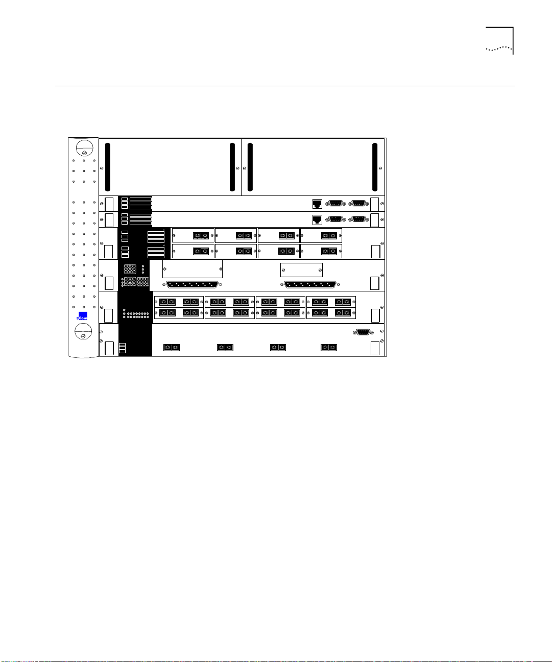
Figure 1 shows the components of the CoreBuilder 7000 family ATM
switch.
Power Supplies
HD
HD
56 8
RX TX
OC-3MM
RX TX
OC-3MM
12 43
A 1-12
5 6 87
100 FX
RX TXMMRX TX
100 FX
RX TXMMRX TX
1 2 4
1000 BASE-SX
1
Figure 1
RX
TX
OC-3MM
RX TX
OC-3MM
100 FX
RX TXMMRX TX
100 FX
RX TXMMRX TX
1000 BASE-SX
2
Components of the CoreBuilder 7000 Family ATM Switch
7
RX
OC-3MM
RX TX
OC-3MM
100 FX
RX TXMMRX TX
100 FX
RX TXMMRX TX
3
1000 BASE-SX
3
TX
Mana gemen t Service P ort
10Base-T
Mana gemen t
10Base-T
OC-3MM
OC-3MM
B 13-24
RX TXMMRX TX
RX TXMMRX TX
RS232
Serv ice P ort
RS232 RS232
RX TX
RX TX
100 FX
100 FX
1000 BASE-SX
4
Control Terminal
RS232
Control Terminal
CB 7000HD Switch Module
CB7000 HD Switch Module
8Port Board
ATM Interface Modul e
CB7400 A TM /Ethernet
Interface Modul e
CB 7600 Fast Ethernet
Interface Modul e
CB7800 Gigabit Ethernet
Interface Modul e
Enclosure
The housing for the CoreBuilder 7000 family ATM switch contains 2 slots
for switching modules and 4 slots for interface cards, 2 places for power
supplies and a ventilator fan tray. The high speed ATM switching
backplane is located inside the back of the surrounding enclosure.
Power Supply
The power supply is located at the top of the front panel. The unit is
switched on and off by connecting and disconnecting the power cord on
the face of the power supply unit. A second power supply may be
installed for redundancy.
Switching Module
The two slots just under the power supply contain switching modules,
one slot for the active switching module and the other slot for the
redundant switching module.
Page 18

18
C
HAPTER
1: O
VERVIEW
The switching module is the core switching engine of the CoreBuilder
7000 family ATM switch, controlling and monitoring passive backplane
and ATM activity. The switching module has a control port for connection
to a terminal, a management port for connection to a network
management station, and a service port for use by 3Com technicians.
Interface Module
The next four slots contain interface modules. These can be of many
different types. See Chapter 2 in the Operations Guide for details.
Fans
For ventilation a fan tray with 6 fans is located at the left side of the unit.
Installing the
CoreBuilder 7000
Family ATM Switch
The CoreBuilder 7000 family ATM switch may be installed according to
the stages shown in Table 6.
Table 6
Installation Stage Chapter
1
2
3
4
5
6
7
8
9
Installing the CoreBuilder 7000 Family ATM Switch
Unpacking the CoreBuilder 7000 family ATM switch
Installing the CoreBuilder 7000 family ATM switch chassis
either on table-top or in a distribution rack
Installing a main and redundant power supply module in the
CoreBuilder 7000 family ATM switch chassis
Installing a main and redundant switch module in the
CoreBuilder 7000 family ATM switch chassis
Setting up switch module hardware redundancy and LANE
redundancy
Installing 4-Port interface modules in the CoreBuilder 7000
family ATM switch chassis
Installing or replacing other interface modules in the
CoreBuilder 7000 family ATM switch chassis
Installing or replacing the fan tray
Connecting to network devices, ATM optical interface,
control terminal, Ethernet port and power source
2
4
5
5
5
5
See respective
guide
5
5
Page 19

Component Summary
19
Starting up the
CoreBuilder 7000
Family ATM Switch
Redundancy in the
CoreBuilder 7000
Family ATM Switch
The CoreBuilder 7000 family ATM switch is powered on and configured
according to the stages shown in Table 7.
Table 7
Stage Chapter
1
2
3
4
5
6
Powering-on and Configuring the CoreBuilder 7000
Powering up the CoreBuilder 7000 family ATM switch
Understanding system states and switching module LEDs
Logging in to the LMA
Configuring the CoreBuilder 7000 family ATM switch by the
Integrated Fast Setup procedure
Performing additional configuration of the CoreBuilder 7000
family ATM switch by individual LMA commands
Viewing network statistics
Family ATM Switch
6
6
7
7
7
7
The CoreBuilder 7000 family ATM switch is designed to meet the
requirements of environments where network interruptions cannot be
tolerated. The CoreBuilder 7000 family ATM switch platform has a fully
redundant design, with dual load-sharing power supplies and redundant
switching engines. All CoreBuilder 7000 family interface cards and
switching engines are hot swappable to ensure continuous operation
during configuration and servicing.
Troubleshooting
For information about determining the required power supply for various
CoreBuilder 7000 family ATM switch installations and providing
redundancy for various power loads. See “Redundant Power Supply” on
page 85.
For information about using the redundant switching module, see
Chapter 10 in the Operations Guide.
In addition to hardware redundancy, the CoreBuilder 7000 family ATM
switch also provides redundant LANE services which are managed by the
Transcend Network Management System. Each switch contains a
complete set of LES and LECS functionality. In case of failure, LANE
services can be transferred to another CoreBuilder 7000 family ATM
switch elsewhere in the network.
This guide contains a number of troubleshooting procedures for solving
common problems. For information about troubleshooting, see
Chapter 8.
Page 20

20
C
HAPTER
1: O
VERVIEW
Page 21
2
U
NPACKING INSTRUCTIONS
This chapter describes how to unpack the CoreBuilder® 7000 family ATM
switch and contains the following topics:
Unpacking the CoreBuilder 7000 Family ATM Switch.
■
Taking Inventory
■
Unpacking the CoreBuilder 7000 Family ATM Switch
Before unpacking the CoreBuilder 7000 family ATM switch, examine it
carefully for any signs of damage. After unpacking the system as
described below, you may begin the appropriate installation procedure in
Chapter 3.
If there are any visible signs of damage to the system packaging, do not
begin installation. Contact 3Com Technical Support or your distributor for
assistance.
To unpack the CoreBuilder 7000 family ATM switch, follow these
instructions:
Remove the clips that attach the shipping container to the shipping tray
1
of the packaging. The clips are located on opposite sides of the shipping
container (two per side).
Slowly lift the shipping container off the shipping tray. The device is now
2
visible.
Remove the accessory box and the mounting brackets from the top foam.
3
The mounting brackets are recessed into the foam.
Lift the top foam off the device.
4
Two persons are required for this step. With each person grasping the
5
hand-hold of the sling with one hand and holding the side of the system
with the other hand, slowly pull the device out of the foam and place it
where desired.
Page 22
22
C
HAPTER
2: U
NPACKING INSTRUCTIONS
Save the packaging in the event that you must return the CoreBuilder
7000 Family to 3Com or your distributor.
Taking Inventory
The CoreBuilder 7000 family ATM switch package should contain the
items described in the following list. Check these items against the
packing slip. Contact 3Com Technical Support at 1-800-992-2446 if any
item is missing.
1 CoreBuilder 7000 family ATM switch
■
1 CD-ROM entitled 3Com Publications On Line. This CD-ROM
■
contains all documentation for the CoreBuilder 7000 Family ATM
Switch Software Version 4.5 and other related products
1 CD-ROM containing the software and Release Notes
■
1 hardware kit including:
■
1 pair of mounting brackets (for distribution rack installation)
■
10 screws, M4 x 8 Phillips (for mounting brackets)
■
4 rubber feet (for table installation)
■
4 screws, M4 x 8 Phillips (for rubber feet)
■
1 or 2 power cord(s) (2.5 meters each)
■
1 strain relief bracket per power cord
■
3 screws, M3 x 8 Phillips
■
Optional accessories that you ordered with your system may be shipped
separately.
Check the packing slip for other items that you ordered.
Page 23
I
NSTALLING A COREBUILDER
7000
3
Safety Precautions
F
AMILY
This chapter contains instructions for installing the CoreBuilder® 7000
family ATM switch on a table top or in a distribution rack and making the
necessary hardware connections. The topics covered in this chapter
include:
Safety Precautions
■
Preparation
■
Table Top Installation
■
Distribution Rack Installation
■
Read the following safety precautions carefully to reduce the risk of
electric shock and fire.
All servicing should be undertaken ONLY by qualified service
■
personnel. There are no user serviceable parts inside the unit.
ATM S
WITCH
The CoreBuilder 7000 family ATM switch internal power supply
■
provides for automatic selection of either 100-120 VAC or 200-240
VAC, 60/50 Hz, as indicated on the safety label adjacent to the power
inlet. ENSURE that the available voltage supply at the mains is within
one of these two ranges.
DO NOT operate the unit in a location where the maximum ambient
■
temperature exceeds 40 degrees C.
Ensure that the chassis ventilation openings in the unit are NOT
■
BLOCKED.
DO NOT plug in, turn on or attempt to operate an obviously damaged
■
unit.
Unplug the power supply cord from the wall socket BEFORE
■
attempting to remove and/or replace the power supply.
Page 24
24
C
HAPTER
3: I
NSTALLING A COREBUILDER
Vorsichtsmaßnahm en
7000 F
The system has a redundant power supply option. Disconnecting one
■
AMILY
ATM S
WITCH
power supply cord disconnects one power supply module only. To
isolate the unit completely from the mains, disconnect all power
supply cords.
Lesen Sie die folgenden Vorsichtsmaßnahmen sorgfältig, um das Risiko
von Stromschlag oder Brandgefahr zu vermindern.
Jede Wartung sollte NUR von befugtem Wartungspersonal
■
durchgeführt werden. Das Aggregat enthält keine vom Anwender zu
wartenden Teile.
Das interne Netzteil des CoreBuilder 7000 family ATM switch
■
ermöglicht automatische Wahl von 100-120 V AC oder 200-240 V
AC, 60/50 Hz, wie auf dem Sicherheitsetikett beim Netzeingang
vermerkt. VERGEWISSERN SIE SICH, daß der vom Netz gelieferte
Strom einer von diesen beiden Spannungsbereichen entspricht.
Nehmen Sie das Gerät NICHT in Betrieb, falls die Temperatur der
■
Umgebung 40 Grad C übersteigt.
Mesures de sécurité
Gehen Sie sicher, daß die Lüftungsöffnungen am Gehäuse NICHT
■
BLOCKIERT sind.
Eine offensichtlich schadhafte Einheit soll weder angeschlossen,
■
eingeschaltet noch in Betrieb genommen werden.
Ziehen Sie das Netzkabel aus Steckdose an der Wand, BEVOR Sie
■
versuchen, das Netzteil zu entfernen und/oder zu ersetzen.
Das System verfügt über ein wahlweises Ersatzstromaggregat.Das
■
Trennen der Verbindung eines Netzkabels unterbricht die Verbindung
nur mit einem Netzteil-Modul. Um das Gerät völlig vom Stromnetz zu
trennen, müssen alle Netzkabel gelöst werden.
Lire attentivement les mesures de sécurité afin de réduire les risques
d'électrocution et d'incendie.
Le service après-vente ne devra être effectué que par un personnel
■
qualifié. Aucune pièce de l'unité ne peut être réparée par le simple
utilisateur.
Page 25

Preparation
Le CoreBuilder 7000 family ATM switch d'alimentation interne permet
■
une sélection automatique de 100 -120 VAC ou 200-240 VAC,
60/50Hz comme stipulé sur le label de sécurité placé près de
l'ouverture d'alimentation. Veiller à ce que le voltage du secteur soit
bien compris entre les valeurs mentionnées ci-dessus.
Ne pas faire fonctionner l'unité dans un endroit où la température
■
ambiante maximale dépasse 40 degrés C.
Ne jamais essayer de brancher, allumer ou faire fonctionner une unité
■
apparemment endommagée.
S'assurer que les ouvertures de la ventilation du chassis de l'unité ne
■
sont pas bloquées.
Débrancher le fil d'alimentation au secteur de la prise murale AVANT
■
d'essayer de déplacer ou de remplacer l'unité d'alimentation.
Le système dispose d'un système redondant d'alimentation au secteur.
■
Le fait de débrancher l'une des sources d'alimentation ne débranche
que l'un des modules d'alimentation au secteur. Pour isoler
entièrement l'unité de toute alimentation, débrancher tous les câbles
d'alimentation.
25
Preparation
Ta bl e To p Installation
Before beginning the installation procedures in this chapter, ensure that
the CoreBuilder 7000 family ATM switch is placed close to the location
where it will be installed and that the mounting brackets and hardware
kit supplied with the system are readily available. You will also need a No.
2 Phillips screwdriver.
The hardware kit contains:
1 pair of mounting brackets (for distribution rack installation)
■
10 screws, M4 x 8 Phillips (for mounting brackets)
■
4 rubber feet (for table installation)
■
4 screws, M4 x 8 Phillips (for rubber feet)
■
The CoreBuilder 7000 family ATM switch is ready for table top installation
as shipped.
Page 26

26
C
HAPTER
3: I
NSTALLING A COREBUILDER
To provide a firmer base for the unit, you can choose to attach four
rubber feet to the switch chassis. Use the rubber feet and the four M4 x 8
Phillips screws included in the hardware kit.
To insert the power supply, switching modules, and interface cards,
configure optical ports for the interface modules and connect network
cabling and power to the unit see Chapter 4.
7000 F
AMILY
ATM S
WITCH
Distribution Rack Installation
Unit and Rack
Preparation
You can mount the CoreBuilder 7000 family ATM switch in a 19-inch
distribution rack. This section describes how to prepare the unit and the
distribution rack, and mount the unit in the distribution rack. Please read
all of the instructions carefully before beginning the installation.
For the basic mechanical and space requirements for the distribution rack,
see “Distribution Rack Requirements” on page 107.
To prepare the CoreBuilder 7000 family ATM switch and distribution rack
for installation:
Attach the mounting brackets onto the sides of the CoreBuilder 7000
1
family ATM switch using the mounting bracket screws (M4 x 8 Phillips).
Determine whether or not the distribution rack has threaded holes. If the
2
holes are threaded, see “Mounting the CoreBuilder 7000 Family ATM
Switch” on page 28.
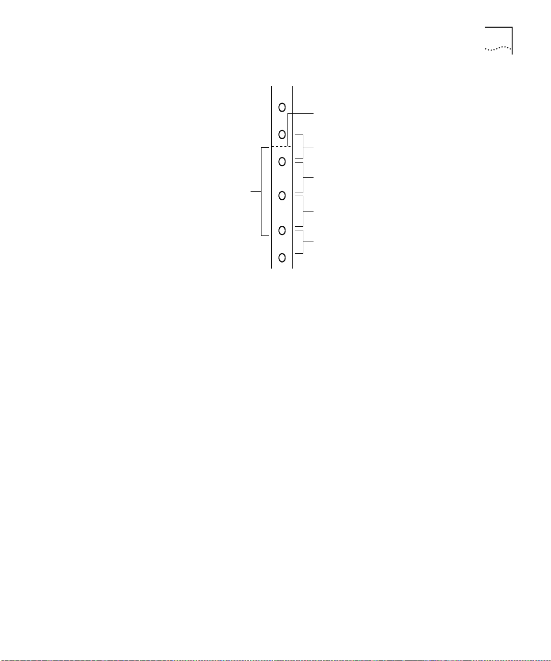
If the holes are not threaded, you must insert “G” clips. To determine
3
where to insert “G” clips, locate the top of a universal mounting hole
pattern on the left mounting rail. In the universal rail pattern, the spacing
between holes is 1/2 inch, 5/8 inch, 5/8 inch, and 1/2 inch. To find the top
of the pattern, locate the midpoint between any two holes that are
spaced half an inch apart. Figure 2 shows the universal mounting hole
pattern.
Page 27
Distribution Rack Installation
Top of a universal mounting
hole pattern
1/2-inch spacing
27
Univers al m ounting
hole pattern
Figure 2
From the top of the universal mounting hole pattern, insert “G” clips in
4
Universal Mounting Hole Pattern
5/8-inch spacing
5/8-inch spacing
1/2-inch spacing
the holes designated for the unit model.
Repeat steps 3 and 4 for the right rail. Ensure that you start on the same
5
hole space.
You are now ready to mount the CoreBuilder 7000 family ATM switch
into the distribution rack.
Page 28
28
C
HAPTER
3: I
NSTALLING A COREBUILDER
7000 F
AMILY
ATM S
WITCH
Mounting the
CoreBuilder 7000
Family ATM Switch
Once the distribution rack is ready, you can mount the CoreBuilder 7000
family ATM switch into the rack.
To mount the CoreBuilder 7000 family ATM switch into the distribution
rack:
Carefully lift the CoreBuilder 7000 family ATM switch into place, aligning
1
the mounting brackets to the holes you have designated for mounting.
A fully-configured CoreBuilder 7000 family ATM switch weighs 43
pounds as shipped. To avoid personal injury, do not lift the unit without
assistance.
While holding the CoreBuilder 7000 family ATM switch in place, firmly
2
insert the mounting screws (10/32 x 1/2 Phillips) into the mounting holes
on both sides of the rack.
The unit is now installed in the distribution rack.
To insert the power supply, switching modules, and interface cards,
configure optical ports for the interface modules and connect network
cabling and power to the unit see Chapter 4.
Page 29
I
NSTALLING AND
C
ONNECTING
4
C
OREBUILDER
This chapter describes how to install and replace the CoreBuilder® 7000
family modules. The following modules are covered.
Power Supply Module
■
Switch Module
■
4-Port Interface Module
■
Fan Tray
■
Connecting to Network Devices
■
The installation procedures of the other modules of the CoreBuilder 7000
family modules are described in their respective guides.
This chapter also describes how to connect the CoreBuilder 7000 family
ATM switch to network devices.
M
ODULES
Safety Precautions
When handling replacement parts, 3Com recommends that you always
use a wrist strap connected to a proper ground. This helps prevent the
module from being damaged by electrostatic discharge. Additionally,
when not in use, the module should be stored in an antistatic bag.
If the system is powered on when you are replacing a module, do not
insert any metal objects, such as a screwdriver or a finger with jewelry, in
the open slot. This could cause burns or other bodily harm, as well as
system damage.
Page 30
30
C
HAPTER
4: I
NSTALLING AND CONNECTING COREBUILDER MODULES
Vorsichtsmaßnahm en
Mesures de sécurité
Wenn Sie Ersatzteile handhaben, benutzen Sie immer ein Band am
Handgelenk, daß gut geerdet ist. Das hilft vermeiden, daß das Ersatzteil
durch elektrostatische Entladung beschädigt wird. Darüber hinaus sollte
ein Modul, wenn nicht benutzt, in einem antistatischen Beutel
aufbewahrt werden.
Steht das System unter Strom, wenn sie ein Modul installieren oder
auswechseln, führen Sie keine Metallgegenstände, wie einen
Schraubenzieher oder einen Finger mit Schmuck in den offenen Schlitz
ein. Das könnte zu Verbrennungen oder anderen Körperschäden führen,
sowie auch zu Schäden am System.
Lors de la manipulation des pièces de rechange, 3Com recommande de
toujours utiliser une bande attachée au poignet et reliée à la terre. Cela
aidera à éviter que la pièce ne soit endommagée par une décharge
électrostatique. De plus, lorsqu'il n'est pas utilisé, le module doit être
conservé dans un emballage antistatique.
Power Supply Module
Si le système est alimenté lors de l'installation ou du remplacement d'un
module, ne jamais insérer d'objet métallique tel qu'un tourne-vis ou un
doigt portant un bijou dans la fente. Cela est susceptible de provoquer
brûlures ou autres dommages corporels, et d'endommager le système.
The CoreBuilder 7000 family ATM switch provides a dual load-sharing
power supply capability where the second unit can serve as a redundant
power supply. For more information, see “Redundant Power Supply” on
page 85.
For certain combinations of installed interface cards, the second power
supply cannot be used as a redundant supply (see “Providing Redundancy
for Various Power Loads” on page 90).
This section discusses the following topics:
Installing a Power Supply Module
■
Replacing a Redundant Power Supply Module
■
Page 31

Power Supply Module
31
Installing a Power
Supply Module
Replacing a
Redundant Power
Supply Module
To install a power supply module:
Orient the module so that its sides enter the guides on either side of the
1
chassis slot.
Slide the module into the chassis until the face panel is flush with the
2
enclosure.
Secure the screws on either side of the front panel.
3
If a redundant power supply is not installed in the second power supply
4
slot, cover the slot with a blank panel for safety.
You can replace the redundant power supply without having to turn off
the system (hot-swap). For more information on the operation of the
redundant power supply module, see “Redundant Power Supply” on
page 85.
To replace a redundant power supply module:
Disconnect the power cord from the power supply.
1
Loosen the screws at the extreme right and left of the power supply, near
2
the handles (see Figure 3).
Grasp the handles of the redundant power supply you want to replace
3
and pull them outward. This ejects the power supply.
Remove the new power supply from its antistatic bag. Place the old
4
power supply in the antistatic bag and set it aside in a safe place.
Orient the power supply so its labelling is upright.
5
Insert the power supply into the chassis by placing it between the guides
6
of the slot and sliding it until it stops.
Tighten the power supply’s securing screws.
7
Connect the power cord to the power supply.
8
Page 32

32
C
HAPTER
4: I
NSTALLING AND CONNECTING COREBUILDER MODULES
Switch Module
Installing a Switch
Module
Figure 3
Hot-Swapping a Redundant Power Supply
The CoreBuilder 7000 family ATM switch provides for a redundant switch
module to ensure continued operation should the main switch module
fail. For more information on the operation of the redundant switch
module, see Chapter 10 in the Operations Guide.
This section includes the following topics:
Installing a Switch Module
■
Replacing a Switch Module
■
Setting up Switch Module Redundancy
■
Setting up Switch Module Hardware Redundancy
■
Setting up Hardware Redundancy and LANE Redundancy
■
To install a switch module in the CoreBuilder 7000 family ATM switch
chassis:
Remove the new card from its antistatic bag.
1
Orient the card so its labelling is upright and make sure the inject handles
2
are in the outward position.
Page 33

Switch Module
Insert the card into the chassis by placing it between the guides of the
3
selected slot and sliding the card until it stops.
Grab both inject handles and push them inward. This locks the card into
4
the chassis. You may have to apply considerable pressure to the handles.
An audible “click” indicates that the connectors have engaged.
Tighten the card’s securing screws. You are now ready to connect cables
5
to the appropriate ports.
33
Replacing a Switch
Module
To hot-swap the switch module:
Disconnect the cables from the card's ports. Ensure that there is a record
1
of where the cables are attached so that you can correctly re-connect
them to the new card.
Loosen the screws at the extreme right and left of the card, near the
2
insert/eject handles.
Grasp the insert/eject handles of the card you want to replace and push
3
them outward. This ejects the card. You may have to apply considerable
force to the handles. You will hear a “click” to indicate that the
connections have separated, and the card will slide slightly forward out of
the CoreBuilder chassis.
Remove the new card from its antistatic bag. Place the old card in the
4
antistatic bag and set it aside in a safe place.
Orient the card so its labelling is upright and make sure the inject handles
5
are in the outward position.
Insert the card into the chassis by placing it between the guides of the
6
selected slot and sliding the card until it stops.
Grab both inject handles and push them inward. This locks the card into
7
the chassis. You may have to apply considerable pressure to the handles.
An audible “click” indicates that the connectors have engaged. Verify
that the card has been properly installed by observing its LEDs.
Tighten the card’s securing screws.
8
Connect cables to the appropriate ports.
9
Page 34

34
C
HAPTER
4: I
NSTALLING AND CONNECTING COREBUILDER MODULES
Setting up Switch
Module Redundancy
Figure 4
Hot-Swapping a Switch Module or Interface Module
This section describes procedures for installing and setting up both a
main and redundant switch module together.
Two different setup procedures are described. The first procedure covers
setting up the main and redundant switch module
hardware redundancy
without setting up LANE redundancy. This procedure only requires
operating the LMA. The second procedure sets up the main and
redundant switch module hardware redundancy as well as LANE
redundancy. It requires both the LMA and the Transcend Enterprise
Manager.
There are two situations where you would use the procedures of this
section:
The initial installation of main and redundant cards.
1
The main card in the first slot has failed and the redundant card in the
2
second slot has taken over as the main card. The failed card in the first
slot has been replaced by a new card and this new card is now the
redundant one.
Page 35

Switch Module
35
Setting up Switch
Module Hardware
Redundancy
Use the following procedure to set up the switch module hardware
redundancy.
Designate and mark the main and redundant switch modules.
1
Insert the switch module you marked as “redundant” in slot 2. Do not
2
insert the switch module you marked as “main” yet.
Turn on the CoreBuilder 7000 family ATM switch.
3
The switch module in slot 2 becomes active.
Run the Integrated Fast Setup procedure (see “Integrated Fast Setup” on
4
page 56.) using the LMA command
(9) FST
Insert the main switch module in slot 1.
5
Reboot the CoreBuilder 7000 family ATM switch using the LMA menu
6
sequence:
(1) SYS / (7 ) RB O
.
The switch module in slot 1 becomes active.
Verify main and redundant switch module status using the LMA
7
command:
(1) SYS / (4) SWM
You should see the following display.
Slot id Slot status Switch type Swit ch mode Memory siz e
------- ----------- ---------------- ------------ -----------
1 Occupied 16x16 ATM switch Active 8M
2 Occupied 16x16 ATM switch Redundant 8M
Run the Integrated Fast Setup procedure using the LMA command
8
(9) FST
to verify the configuration in the main switch module.
The switch is now operational.
Setting up Hardware
Redundancy and
LANE Redundancy
This section presents a procedure for setting up both switch module
hardware redundancy and LANE redundancy in the same session. Both
the LMA and the Transcend Enterprise Manager are used.
Page 36

36
C
HAPTER
4: I
NSTALLING AND CONNECTING COREBUILDER MODULES
General Description of the Procedure
The following is a general description of the procedure for orientation
purposes only. When you perform the procedure, use the detailed steps
in the following sections.
Install both switches in chassis and run CFGFRMAT.BAT on each one.
1
Connect Ethernet ports of each switch module and install at least one
interface card in the chassis.
Configure the first switch using the Integrated Fast Setup of the LMA and
2
do not reboot the switch in the Integrated Fast Setup.
Reboot the switch after one minute using the LMA menu.
3
Answer “no” to the prompt “Erase the setup parameters?” and use the
4
LMA to check that all configuration parameters (i.e., database, IP, NNI
etc.) have passed successfully to the second switch module.
Configure LANE redundancy in the first switch using the Transcend
5
Backbone and Services Setup window and close the window when
finished.
Reboot the switch after one minute
6
Configure LANE redundancy in the second switch module using the
7
Transcend Backbone and Services Setup window and close the window
when finished.
After one minute use the MIB browser to check the LECS order list and
8
the Backbone and Services Setup window to check the LECS database.
Reboot the box.
9
Check the second switch using the MIB browser to check the LECS order
10
list and the Backbone and Services Setup window to check the LECS
database.
Preparatory Steps
Carry out the following preparatory steps.
Install main and redundant switch modules in the switch module slot 1
1
and slot 2 respectively (see“Installing a Switch Module” on page 32
not run the Integrated Fast Setup yet.
Each time the switch is rebooted during this procedure the cards change
roles. The main card becomes the redundant card and vice versa. The
main card can always be identified by its ACT LED flashing once every
two seconds. The ACT LED of the redundant card flashes at a lower rate.
). Do
Page 37

Switch Module
Verify that at least one interface card of any type is installed in the
2
CoreBuilder chassis in any interface card slots 3-6. Data is transferred
between switch modules via a communications chip on an interface card.
Verify that the Ethernet management ports in both switches are
3
connected to the NMS station. They can either be connected through a
hub to the NMS station or through an Ethernet interface card in the same
chassis, such as the CoreBuilder 7400 High Density Ethernet/ATM
interface card, to the NMS station.
During the procedure you will need to verify connectivity between the
NMS station and the switch by pinging the switch module from the NMS
station.
Connectivity between the switch module and its attached devices is
established by a coldStart trap transmitted by the switch module when it
boots. The coldStart trap causes a device to learn the MAC address of the
switch module. However, there are certain devices, for example, a Solaris
station, which will not learn a new MAC address for an IP when one
already exists. If you are using one of these devices as an NMS station,
and you are unable to ping the switch module, try erasing the switch
module’s MAC address from the device’s ARP table and ping again.
37
Verify that the RS-232 terminal line is connected to the console port on
4
the main switch module.
Procedure Execution
Reset the configuration of both switch modules by executing the
1
CFGFRMAT.BAT file supplied with your software.
To execute the CFGFRMAT.BAT file proceed as follows:
Perform the LMA command (1) SYS / (3) LOA / (3) LCL / 1 to put the
a
system in Load Mode: Load.
Reboot the switch using the LMA menu command: (1) SYS / (7) RBO.
b
The switch will reboot in debug mode.
Transfer the RS-232 cable to the service port of the main switch
c
module.
From a DOS window on the LMA terminal execute
d
>
cfgfrmat com speed
where “com” is the communications port you are using and “speed”
is 115200 for a CoreBuilder 7000HD switch module and 57600 for a
CoreBuilder 7000 switch module.
Page 38

38
C
HAPTER
4: I
NSTALLING AND CONNECTING COREBUILDER MODULES
Transfer the RS-232 cable to the service port of the redundant switch
e
module.
Repeat step d)
f
Transfer the RS-232 cable to the console port of the main switch
g
module.
Hardware Redundancy Setup
Set up the main switch module using the Integrated Fast Setup (see
2
“Integrated Fast Setup” on page 56
Integrated Fast Setup procedure (answer “no” to the prompt).
The main menu appears.
Wait for one minute to allow the configuration data to transfer from the
3
main switch module to the redundant switch module.
Reboot the switch using the LMA menu sequence: (1) SYS / (7) RBO. This
4
causes the configuration data to be recorded in flash memory and also
causes the redundant switch module to become the main switch module.
After the switch reboots, answer “no” to the prompt: “Do you wish to
5
erase the setup parameters”.
). Do not reboot the switch from the
Run the Integrated Fast Setup procedure as in step 2) to verify that the
6
setup parameters have been transferred correctly to the second switch
(the Integrated Fast Setup procedure now displays the setup parameters
resident in the second switch module). Press Enter repeatedly to verify
these parameters; do not enter new values.
Verify that the ELAN names in the LECS database are identical in both
7
switch modules. Use menu item (2) LEM/(1) LCS/(5) LNT to check that the
LECS database of the second switch includes the ELAN name of the first
switch. For example, Elan6666_0 - Elan6666_15
NMS-Based LANE Redundancy Setup
Verify connectivity between the switch module and the NMS station by
8
pinging the switch module from the NMS station.
Load the Transcend application and open the Wizard Tool from the
9
ATMvLAN tool bar
Open the Backbone and Services Window.
10
Configure the LECS order as desired and press the Apply button.
11
Configure the LECS database. Add all the primary and redundant ELAN
12
names desired to the LECS database and press Apply. Make a list of the
Page 39
Switch Module
ELAN names you have selected. You will need them for setting up the
other switch module.
When finished, close the Backbone and Services window.
13
Wait one minute to allow the LECS order database to transfer to the
14
other switch module.
The LECS ELAN database does not transfer automatically.
39
Reboot the switch using the LMA menu sequence:
15
(1) SYS / (7) RBO
The purpose of this step is to make the first switch module active in order
to set up the LANE services there.
After the first switch boots, check its connectivity with the NMS station as
16
in step 8).
Perform steps 10) and 12) using the same list of ELANs.
17
Wait one minute.
18
Verifying LANE Redundancy Setup
Use the MIB browser under the Transcend tools menu and browse
19
through the MIB to verify that all the information regarding the LECS
order list has been transferred correctly.
Look in the following MIB location:
private
■
enterprises
■
atmForum
■
atmForumNetworkManagement
■
atmLanEmulation
■
elanMIB
■
.
elanLecsGroup
■
elanLecsConfGrou.
■
lecsConfTablelecsConfEntry
■
lecsAtmAddrSpec
■
Press start query. The LECS order list is displayed on the bottom window.
Close the Backbone and Services Select window.
20
Open the Backbone and Services Select window again and use it to check
21
that the LECS database is correct.
Page 40

40
C
HAPTER
4: I
NSTALLING AND CONNECTING COREBUILDER MODULES
This item could be done through the LMA but it is preferred to do so
through the NMS since the LMA will not show any redundant LES that
exists.
Reboot the switch using the LMA menu sequence: (1) SYS / (7) RBO. The
22
purpose of this step is to make the second card active in order to check
the LANE services there.
After the second switch module boots, verify connectivity with the NMS
23
station as in step 8).
Perform step 19) and 20) to verify LECS order.
24
Open the Backbone and Services Select window again and use it to check
25
the LECS database is correct.
The hardware and LANE redundancy procedure is finished.
Page 41

4-Port Interface Module
41
4-Port Interface
Module
ATM Interface
Daughter Cards
This section contains the following topics:
ATM Interface Daughter Cards
■
Installing the ATM Interface Daughter Cards
■
Installing a 4-Port Interface Module
■
Replacing a 4-Port Interface Module
■
Each of the four ATM interface receptacles of the 4-Port ATM Interface
module can be configured to support the following types of ATM
daughter cards:
OC-3 multi-mode (MM) fiber link, single-mode (SM) fiber link
■
DS-3 coaxial cable
■
E-3 ATM 34.368 Mbits/sec WAN interface
■
Figure 5 shows the OC-3 daughter card.
Figure 5
OC-3 Daughter Card
Figure 6 shows the DS-3 daughter card.
Page 42

42
C
HAPTER
4: I
NSTALLING AND CONNECTING COREBUILDER MODULES
Figure 6
DS-3 Daughter Card
Figure 7 shows the E-3 daughter card.
Figure 7
E-3 Daughter Card
Page 43

4-Port Interface Module
43
Installing the ATM
Interface Daughter
Cards
The 4-port ATM interface module can hold up to four ATM interface
daughter cards. The installation procedure of the 4-port ATM interface
module comprises two stages. First, you install the ATM interface
daughter cards in the 4-port ATM interface module. Then, you install the
4-port ATM interface module into the CoreBuilder 7000 family ATM
switch chassis.
To install the ATM interface daughter cards perform the following
procedure:
Select the individual daughter cards that are to occupy the interface card’s
1
four openings.
Align each module with the front panel aperture as shown in Figure 8
2
and press down to engage the strip connectors on the underside of the
module. Three screws anchor each module to its seat on the interface
card. Interface openings reserved for future use should be covered with
blank panels. Used interfaces should use the coax or optical panels as
covers.
Installing a 4-Port
Interface Module
Figure 8
4-Port ATM Interface Module
When the ports of the interface module have been fitted with the
appropriate daughter card, you install the 4-port interface module into
the CoreBuilder 7000 family ATM switch chassis.
To install the 4-port interface module:
Orient the interface module so its labelling is upright and be certain that
1
the inject handles are in the outward position.
Insert the card into the chassis by placing it between the guides of the
2
selected slot and sliding the card until it stops.
Be certain that the card sits in the guide slots on either side. Be sure that
3
the loose screws do not interfere with card insertion.
Page 44

44
C
HAPTER
4: I
NSTALLING AND CONNECTING COREBUILDER MODULES
Grab both inject handles and push them inward. This locks the card into
4
the chassis. You may have to apply considerable pressure to the handles.
An audible “click” indicates that the connectors have engaged.
Tighten the card’s securing screws. You are now ready to connect cables
5
to the appropriate ports of the module.
Replacing a 4-Port
Interface Module
Fan Tray
To replace individual daughter cards, or to replace the entire interface
module:
Disconnect the cables from the card's ports. Ensure that there is a record
1
of where the cables are attached so that you can correctly re-connect
them to the new card.
Loosen the screws at the extreme right and left of the card, near the
2
insert/eject handles.
Grasp the insert/eject handles of the card you want to replace and push
3
them outward. This ejects the card. You may have to apply considerable
force to the handles. You will hear a “click” to indicate that the
connections have separated, and the card will slide slightly forward out of
the CoreBuilder chassis.
If you are replacing the entire interface card, remove the new card from
4
its anti-static bag. Place the old card in the anti-static bag and set it aside
in a safe place.
To replace the fan tray:
Loosen the screws at the top and bottom of the fan tray.
1
Pull the fan tray out of the chassis.
2
Remove the new fan tray from its antistatic bag. Place the old fan tray in
3
the antistatic bag and set it aside in a safe place.
Connecting to Network Devices
Orient the fan tray so its labelling is upright.
4
Insert the new fan tray into the chassis by placing it between the guides
5
of the slot and sliding it until it stops.
Tighten the fan tray’s securing screws.
6
This section describes how to connect the CoreBuilder 7000 family ATM
switch to different types of network devices.
Page 45

Four types of connections are required:
Connecting to an ATM Optical Interface
■
Connecting the Control Terminal
■
Connecting to the Ethernet Port
■
Connecting to the Power Source
■
Connecting to Network Devices
45
Connecting to an
ATM Optical Interface
Table 8
Power Budget for Various 3Com Products
To connect a CoreBuilder 7000 family ATM switch port to another
CoreBuilder unit, to a LinkSwitch 2700 ATMLink adapter, or to any device
with an ATM optical interface:
Prepare an optical cable (Tx Rx). You may want to mark the ends of the
1
cable so you can identify them.
Snap the cable into a CoreBuilder 7000 family ATM switch port in one of
2
the interface modules.
Snap the other end of the cable into the selected optical interface of the
3
other ATM device. Make sure that each wire connects to Rx on one end
and Tx on the other.
Repeat steps 1-3 for all ATM port connections to the CoreBuilder.
4
Perform steps 1-4 above when connecting a DS-3 coax cable set (Rx and
Tx).
Fiber Optic Power Budget of 3Com Products
Table 8 shows the power budget of various 3Com products. Use this
table when you calculate the length of fiber optic cable you need to
connect to the CoreBuilder 7000 family ATM switch. See fiber optic cable
manufacturers data for more information.
.
Product
4-Port/8-Port
OC-3 MM
4-Port/8-Port
OC-3 SM
CoreBuilder
7201 (ATM port)
Min TX.
Mode
(nm)
MM-1300 -19 -30 11 2 HP#:HFBR-5205
SM-1300 -15 -33 18 15 SDX-1155B
MM-1300 -19 -30 11 2 HP#:HFBR-5205
O-Pwr
(dBM)
Receiver
Sens.
(dBM)
Budget
(dB)
Distance
(KM)
Specification
Page 46

46
C
HAPTER
4: I
NSTALLING AND CONNECTING COREBUILDER MODULES
Table 8
Product
CoreBuilder
7201 (ATM port)
CoreBuilder
7200F - Ethernet
CoreBuilder
7200F - Ethernet
CoreBuilder
7600FX
CoreBuilder
7600FX
OC-12 MM-1300 -19 -26 7 0.8 HP#:HFBR-5208
OC-12 SM -15 -28 13 15 HP#:SDX-1622
Power Budget for Various 3Com Products (continued)
Mode
(nm)
SM-1300 -15 -33 18 15 SDX-1155B
MM-820 -7.6 -15.1 7.5 HP#:HFBR-2416TC
SM N/A
MM-1300 -19 -31 12 HP#:HFBR-5103
SM N/A
Connecting the
Control Terminal
Min TX.
O-Pwr
(dBM)
The CoreBuilder 7000 family ATM switch can be configured via the LMA
using the Administration Console terminal (VT100) or terminal emulator
Receiver
Sens.
(dBM)
Budget
(dB)
Distance
(KM)
Specification
HP#:HFBR-1414T
(Windows).
To connect a terminal to the CoreBuilder 7000 family ATM switch control
port:
Connecting to the
Ethernet Port
Prepare an RS-232 shielded cable (9 pin-to-9 pin or 9 pin-to-25 pin, as
1
dictated by the terminal you wish to use).
Configure the terminal: 19200 baud, 8 data bits, 1 stop bit, no parity,
2
xon/xoff flow control.
Push the DCE side of the cable onto the Control port of the switch
3
module and screw it into place.
Connect the other end of the cable to the terminal.
4
In case you have installed a redundant switch unit, it is sufficient to
connect the RS-232 line to either the active switch control port or to the
redundant switch control port.
The Ethernet port is used for connecting directly to a Transcend Network
Management System terminal for management purposes.
Page 47

Connecting to Network Devices
47
In case you have installed a redundant switch module, its Ethernet port
must also be connected directly to the Transcend NMS terminal.
Another way of connecting the Ethernet port to an out-of-band Ethernet
network is to connect it to a CoreBuilder 7200 Ethernet/ATM Interface
Card or a CB7400 High Density Ethernet/ATM Interface Card installed in
the same chassis.
Connecting to the
Power Source
This section describes how to connect the CoreBuilder 7000 family ATM
switch to the power source.
Selecting a Power Cord
The following power cords and accessories are supplied with the unit:
1 or 2 power cord(s) (2.5 meters each)
■
1 strain relief bracket per power cord
■
3 screws, M3 x 8 Phillips
■
The power cord supplied with the unit can be used with loads of up to 5
Amps AC.
If power cord(s) WERE NOT supplied with the unit, choose a cord based
on the following information:
For units installed in the USA or Canada: Select a flexible,
■
three-conductor power cord that is UL-listed and CSA-certified, with
individual conductor wire size of #18 AWG, and with a maximum
length of 4.5 meters. The power cord terminations should be NEMA
Type 5-15P (three-prong earthing) at one end and IEC appliance inlet
coupler at the other end.
The following types are acceptable: SV, SVE, SVO, SVT, SVTO, SVTOO,
■
S, SE, SO, SOO, ST, STO, STOO, SJ, SJE, SJO, SJOO, SJT, SJTOO, SP-3,
SPE-3, SPT-3, G, W.
For units installed in all other countries, select only a flexible,
■
three-conductor power cord, approved by the cognizant safety
organization of your country. The power cord must be of the type HAR
(Harmonized), with an individual conductor wire size of 0.75 sq.mm.
The power cord terminations should be a suitably-rated earthing-type
plug at one end and an IEC appliance inlet coupler at the other end.
Both of the power cord terminations must carry the certification label
(mark) of the cognizant safety organization of your country.
Page 48

48
C
HAPTER
4: I
NSTALLING AND CONNECTING COREBUILDER MODULES
Plugging in the Unit
To plug in the unit:
Plug the power cord into the power source.
1
Plug the other end of the cord into the AC inlet located in the topmost
2
section of the CoreBuilder 7000 family ATM switch front panel. Make
sure the power cord is fully seated. A green power LED on the power
supply should be lit. The unit is automatically powered up when the
power cord is plugged in.
Be certain that the fans are working. If the fans are not working, unplug
3
the unit immediately and see “Fans do not rotate” on page 94
.
Page 49

5
P
OWER
This chapter describes the system states of the CoreBuilder® 7000 family
ATM switch including power-on and some basic diagnostic information to
help you verify normal operation of your CoreBuilder system.
This chapter describes the following topics:
System States
■
System Power-on
■
4-Port Interface Module LEDs
■
-O
N
System States
System States and
Switching Module
LEDs
This section describes the different system states of the 8-Port Board and
how they are indicated on the LED display.
The system states are:
Power-on
■
Normal operation
■
Hardware fault
■
Software fault
■
No power to unit
■
LED indicators are located on the front panels of the CoreBuilder 7000, its
power supply, switching modules, and interface modules. These LEDs
indicate the current system state of the CoreBuilder unit and its
components. Front panel LEDs can be extremely useful in determining the
cause of specific problems.
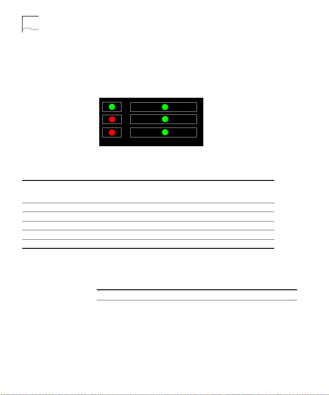
The system state in which the CoreBuilder 7000 unit is currently
operating is displayed by the switching module system status LEDs.
Referring to Figure 9, these are the three LEDs: PWR, FAIL, and ACT(ive)
Page 50
50
C
HAPTER
5: P
OWER-ON
on the left side of the LED panel. Table 9 shows the correlation between
the current system state and SYS LEDs display. For example, during
normal operation the PWR LED is on, the FAIL LED is off and the ACT LED
is flashing. The LEDs on the right side of the panel indicate the status of
the Ethernet port, the Service port and the Control port.
PWR
FAIL
ACT
Figure 9
Table 9
System State
Power-on On Off On On Flashing Flashing
Normal operation On Off Flashing On On On
Hardware fault On On Off Off Off Off
Software fault On Off Not flashing Undetermined Undetermined Undetermined
No power to unit Off Off Off Off Off Off
CoreBuilder System States
Power
(green)
Fail
(red)
10BASE-T
Service
Control
Switching Module LEDs
Activity
(yellow)
Status
Status
Status
10BASE-T
Status
(green)
Service Port
Status
(green)
Control
Terminal Status
(green)
The following table also provides information about the LED display of
system states but is organized by system status LED.
Table 10
Description of Switching Module LEDs
LED Color Description Source
PWR (Power) Green DC power input active. Hardware
ACT (Activity) Yellow Should blink continuously when
FAIL Red CPU failure. Hardware
10BASE-T
STATUS
Green 10BASE-T link OK. The Ethernet link is
operational.
active.
Software
CPU or
Watchdog
Hardware
Ethernet
controller
Page 51

System Power-on
51
System Power-on
Software Loading
and Diagnostics
Table 10
SERVICE PORT
STATUS
CONTROL
TERMINAL
STATUS
Description of Switching Module LEDs (continued)
Green RS232 service port link OK – should be
blinking during power on.
Green RS232 control terminal port link OK –
should be blinking during power on.
Software
Software
This section describes the stages of system power-on of the CoreBuilder
7000 family ATM switch.
Apply electrical power to the system by inserting the power cord in the
power supply unit. The power supply indicator lights and the CoreBuilder
7000 family ATM switch automatically runs diagnostic software. This
software verifies that every component in the system is fully functional
before the system becomes active on the network. Diagnostics should
take sixty seconds or less.
If any component fails power-on diagnostics, the system either fails to
power on or it keeps faulty modules off-line. Once the system comes up,
you can check to see which modules, if any, have failed diagnostics by
checking the LED panels; in-depth information is available by viewing the
system configuration screens on the administration console.
Indicators
4-Port Interface Module LEDs
All interface and switching unit indicators light at the start of the
power-on diagnostic sequence, then go out briefly. General activity LEDs
light up as the system checks the switching and interface modules. Finally,
individual port indicators go on as the system discovers active
connections residing on the interface modules. The 10BaseT indicator on
the interface module is on during normal function, even if there is no
active 10BaseT management link.
Figure 10 shows the 4-port interface module LEDs. Table 11 and Table 12
list the permanent 4-port interface module panel LEDs.
Page 52

52
C
HAPTER
5: P
OWER-ON
DS-3 Status LEDs
Figure 10
Table 11
LED Color Description Source
PWR (Power) Green DC power input active. Hardware
FAIL Red CPU failure. Hardware
ACT (Activity) Yellow Should blink continuously when
Table 12
LED Color Description Source
LINK STATUS Green ATM physical layer is connected and
FAIL Red ATM interface port test failure. Software
ACT (Activity) Yellow Reception and transmission of cells on
Interface Module LEDs
Description of Interface Module LEDs
CPU or
Watchdog
Software
operational.
Description of Interface Module LEDs for Each Port
Software
has no error.
Software
ATM link – should flash to indicate
traffic.
The DS-3 status LEDs are found on the front panel of the DS-3 piggy.
Table 13 lists the LEDs of the DS-3 piggy.
Page 53

4-Port Interface Module LEDs
53
Figure 11
Table 13
LED Color Description
LOS
Loss of Signal
FERF
Far End Rx Failure
Signal
AIS
Alarm Indication
Signal
LOF
Loss of Frame
DS-3 Status LEDs
DS-3 Status LEDs
Green
Yellow
Blue
Red
There is a signal on Rx (normal state).
On:
No signal on Rx (problem with Rx).
Off:
FERF in incoming frames (the peer reports
On:
about its Rx problem).
No FERF in incoming frame.
Off:
AIS signal is present for at least 5 sec. (the
On:
peer reports about its problem).
No AIS signal present for at least 5 sec.
Off:
(normal state).
LOF is present for at least 5 sec. (problems
On:
with Rx).
No LOF for at least 15 sec.
Off:
Page 54

54
C
HAPTER
5: P
OWER-ON
Page 55

C
ONFIGURING THE
6
C
OREBUILDER
S
WITCH
This chapter describes the initial configuration of the CoreBuilder® 7000
family ATM switch. Using the terminal connected to the control port, you
log into the system and assign network addresses to the CoreBuilder
7000 family ATM switch. This procedure enables the management of the
site to recognize and communicate with the CoreBuilder 7000 family
ATM switch. You also specify ATM connections between addresses, using
the ATM protocol you have selected.
The topics covered in this chapter include:
Logging in to the LMA
■
Integrated Fast Setup
■
Additional Switch Configuration
■
Viewing Network Statistics.
■
Storing and Retrieving Configuration Parameters
■
Upgrading from E-IISP to PNNI
■
7000 F
AMILY
ATM
Logging in to the
LMA
When you boot the CoreBuilder 7000 family ATM switch the following
login screen appears:
------ -------------------------
- CoreBuilder 7000 -
- -
- ATM Backbone Switch -
------------------------------Access level (read, write, admin):admin
Password:
Page 56

56
C
HAPTER
6: C
ONFIGURING THE COREBUILDER
To log in to the LMA:
Enter your access level (default is admin)
1
Enter your password
2
After a successful login the LMA Main Menu is displayed as shown in
Figure 12.
==========
(1) SYS: Platform config ->
(2) LEM: Lan Emulation ->
(3) CON: Connections ->
(4) STS: Statistics ->
(5) DIA: Testing & Diagnostics ->
(6) FTR: ATM features
(7) LOG: Logout
(8) VER: Version
(9) FST: Fast Setup
7000 F
CB7000 switch module - Main Menu:
AMILY
ATM S
WITCH
Integrated Fast Setup
Figure 12
LMA Main Menu
This section describes the Integrated Fast Setup procedure and contains
the following topics:
Setup Modes
■
Setup Procedure Sections
■
Entering Data
■
Navigation Aids
■
Integrated Fast Setup Operation
■
Use the Integrated Fast Setup procedure to configure the minimum set of
parameters needed to enable the CoreBuilder 7000 family ATM switch
and its attached devices to function in the network.
With this procedure you can configure both the CoreBuilder 7000 family
ATM switch card and all CoreBuilder 7X00 interface cards installed in it in
one session.
Page 57

Integrated Fast Setup
57
In certain cases you will need to use the Fast Setup procedure of
individual CoreBuilder 7X00 interface cards, in addition to the Integrated
Fast Setup procedure, to correctly configure your system.
This section presents the Integrated Fast Setup of the CoreBuilder 7000
family ATM switch card. It also explains when to use the Integrated Fast
Setup of the CoreBuilder 7000 family ATM switch card and when to use
the Fast Setup of an individual Corebuilder 7X00 interface card. For
detailed information about how to use the Fast Setup of an individual
Corebuilder 7X00 interface card, see the User Guide of the specific
interface card.
Chassis-oriented Setup
The Integrated Fast Setup procedure is based on the concept that the
CoreBuilder 7000 family ATM switch chassis together with its installed
interface cards is viewed as an integrated unit. The advantage of this
point of view is its simplicity: it is not necessary to remember in which slot
each interface card is installed or even which type of interface card is
installed. Attention is focussed on configuring the ports of the chassis.
The procedure automatically determines the ports that are available in the
chassis and presents them by type (Ethernet, Fast Ethernet, ATM) for
configuration. The port location is displayed by the notation <slot.port>
For example <3.1> refers to slot #3, port #1.
.
Chassis-wide VLANs
With the Integrated Fast Setup, Virtual LANs (VLANs) can be created
across the entire chassis. VLANs are set up in two stages. First, in the LE
Client section, a number of
potential
VLANs are created according to the
requirement of the network. Next, in the Virtual Network Configuration
section, the potential VLANs become actual VLANs by having ports
assigned to them.
You need to define an administration “admin” VLAN to maintain SNMP
connectivity to each device in the network. Using the Integrated Fast
Setup you define one admin VLAN for the chassis; there is no need to
define separate admin VLANs for each interface card.
Note that from software version 3.5 on, the “admin” VLAN can now be
called by any other name providing the same name is used consistently in
the CB7000 and in all installed CB7X00 interface cards. When using the
Integrated Fast Setup, the name for the admin VLAN which is specified
for the switch module will be automatically chosen for the other modules
Page 58

58
C
HAPTER
6: C
ONFIGURING THE COREBUILDER
housed in the same CoreBuilder 7000 family ATM switch chassis,
overriding any existing admin VLAN names.
7000 F
AMILY
ATM S
WITCH
Setup Modes
The Integrated Fast Setup provides two setup modes: the “Full” setup
mode and the “Switch” setup mode.
Full Setup Mode
The Full setup mode configures both the CoreBuilder 7000 family ATM
switch and the installed interface cards. It sets the required parameter
values in all the installed interface cards. The Full setup mode presents
only the most critical parameters; default values are assumed for the
remaining parameters.
This method is recommended for most users, especially for initial setup.
Only those systems that require specific parameter settings in one or
more of the installed interface cards will require the Switch setup mode
described in the next section.
Switch Setup Mode
The Switch setup mode focuses only on the CoreBuilder 7000 family ATM
switch and its ATM ports. The Switch setup mode allows you to retain
special settings in the interface cards. In this mode, the installed interface
card configurations cannot be changed. If you want to alter the settings
in an interface card, use the Fast Setup of that interface card after you are
finished using the Switch setup procedure.
Setup Mode Selection
If one of the following conditions is detected, the operator is prompted
to choose between the Switch and Full setup modes:
A Subnet Mask, Default Gateway or NMS Address different from that
■
of the CoreBuilder 7000 family ATM switch
A VLAN whose ATM connection is set to “No”
■
The name of the ELAN to which the default admin port (Port #1 in
■
each slot) is attached is not the same in all interface cards.
If none of these situations is detected, Full setup mode is automatically
selected.
Page 59

Integrated Fast Setup
If Full setup is selected, the parameters in the interface cards revert to
their default values.
Setting Special Parameters
If one or more individual interface cards requires one of the special
situations referred to in the previous section or needs to remain
unaltered, you need to do one of the following:
Use the Switch setup mode of the Integrated Fast Setup to set up the
■
CoreBuilder 7000 family ATM switch only and then use the Fast Setup
of each installed interface card separately.
Use the Full setup mode of the Integrated Fast Setup to configure the
■
CoreBuilder 7000 family ATM switch and all installed interface cards
and then use the Fast Setup for the particular interface card in order to
restore its special parameter values.
59
Setup Procedure
Sections
The Integrated Fast Setup procedure contains the following sections:
Table 14
Setup Section Description
1
2
3
4
5
6
7
8
9
10
11
Setup Procedure Sections
Routing Mode
Network Prefix
PNNI Parameter
LE Parameters
LECS Address
FastBUS Configuration
Interface Type
LE Client Configuration
Virtual Network
Configuration
Admin VN Management
Configuration
Confirmation
Set the Routing Protocol to be used
Set Network Prefix for CoreBuilder 7000
Set the PNNI node level (for the PNNI protocol —
Version 4.5 extended only)
Set LE Parameters for CoreBuilder 7000 (LECS
and LES states)
Set resident active LECS address for CoreBuilder
7000
Configure the FastBUS card if installed.
Set the interface type port parameters for
CoreBuilder 7000
Define potential VLANs by assigning names to
ELANs. Exit this section by pressing Enter only.
Assign chassis ports to potential VLANs.
Set up admin VLAN in all modules including
setting IP address
Confirm setup
Page 60

60
C
HAPTER
6: C
ONFIGURING THE COREBUILDER
7000 F
AMILY
ATM S
WITCH
Entering Data
Navigation Aids
The Integrated Fast Setup procedure runs sequentially through the
relevant data for all of the sections, displaying a prompt for each data
item and a default value. If you want to change the default, enter the
desired value in place of the default. If you want to accept the default,
press Enter.
Default Parameter Values
The default parameter value displayed at the prompt is the value stored in
flash memory. In case there is no value in flash memory, the factory
default value is displayed.
Table 15 lists the short-cut characters you can use to move between
sections of the Integrated Fast Setup procedure:
Table 15
Type: To Go:
< Back to previous section
> To next section
>S To section indicated by double-underlined identifier letter S in section
\ Back to beginning of setup
$ To end of setup
Integrated Fast Setup Procedure Navigation Aids
title
Integrated Fast Setup
Operation
You initiate the Integrated Fast Setup from the LMA Main Menu of the
Corebuilder 7000 family ATM switch (see Figure 12).
To begin the Integrated Fast Setup process, select the menu item:
(9) FST: Fast Setup
Note that the Integrated Fast Setup “Full” setup mode may override any
specific configurations that have previously been carried out in any of the
installed interface cards (see “Setup Modes” on page 58). The following
warning message is displayed when this is about to occur:
***Note: Full fast setup, special module configuration will
be overridden.
The following message appears on the screen.
Page 61

Integrated Fast Setup
Now reading the modules configuration, please wait ...
Special module configuration will be overridden by fast setup.
continue full fast setup or only switch fast setup (S<witch>, F<ull>): F
***Note: Full fast setup, special module configuration will be overridden.
Fast Setup Utility
==================
The flash configuration will be displayed below;
Update if needed, and then hit Enter.
To move between sections, enter the following characters at end of line:
< > - Back and forth in sections >S - Jump to section ID S
\ - Back to beginning of setup $ - To end of setup
Only in Virtual Network Configuration section (group=slot; item=port):
}G - Jump to group #G +I - Jump to item #I
* - Update all group items ** - Update all section items
.T - Assign a VLT tag #T
61
Routing Mode Section
In this section you are prompted to select
PNNI or E-IISP as the routing protocol to be used. Enter 1 for PNNI or 0 for
E-IISP.
Routin g mo de
=----- -- -- -Select routing mode (1-PNNI, 0- E-IISP) : 1
PNNI is available in version 4.5 extended only.
Network Prefix Section
In this section you are prompted for the
network prefix of the switch. Enter values as appropriate. The following
example shows a typical network prefix setting.
Page 62

62
C
HAPTER
6: C
ONFIGURING THE COREBUILDER
Network Prefix
-------------
=
Network Prefix(In HEX): 47.00.00.00.00.00.3c.00.00.a*
7000 F
AMILY
ATM S
WITCH
PNNI Parameter Section
If PNNI was selected as the routing mode, in
this section you are prompted to enter the PNNI node level, i.e., the
hierarchy level of the peer group to which it the node belongs. Enter a
value in the range 0 to 104.
PNNI Parameters
=-------------Enter PNNI Node Level [0 to 104]: 72
LE Parameters Section
In this section you are prompted to enable or
disable the resident LECS and LES of the switch. Enter values as follows:
At the “Resident LECS state” prompt, enter
1
or enter
to disable the resident LECS.
0
to enable the resident LECS
1
If you enter 1, the resident LES will be enabled automatically and no
further prompt will be displayed. If you enter 0, the “LES state” prompt
will be displayed.
At the “LES state” prompt, enter
2
to enable the resident LES or enter 0
1
to disable the resident LES.
The following example shows a typical LAN Emulation configuration.
LE para met er s
=----------- Resident LECS state (1-Enable, 0-Disable): 0
LES state (1-Enable, 0-Disable): 1
LECS Address Section
This section prompts you for the ATM address
of the LECS. Enter the complete LECS address; the network prefix is
identical to the network prefix of the switch. The following example
shows a typical LECS Address configuration:
Page 63

Integrated Fast Setup
LECS Ad dre ss
--=--------Activ e LEC S ad dr :47.00.0 0.0 0.00.00. 3c.00.00. a0 .00.00.0 0. 00.a0.3e. 00 .00.01.00
63
In PNNI mode, this section is not relevant and an appropriate message is
displayed.
FastBUS Configuration Section
This section prompts you to
configure the FastBUS module. If no FastBUS module is installed, this
section is skipped by the Integrated Fast Setup.
To configure the FastBUS:
At the prompt, enter
1
to enable the FastBUS module or enter 0 to
1
disable it.
At the prompt, enter a number in the range
2
to select the capacity of
1-4
Bank 1 from the list of four possibilities:
Options: 1-6*10MB/s
2-3*20MB/s
3-2*30MB/s
4-1*60MB/s
The factory default is 4.
Your choice is displayed.
As in step 2, select the capacity of Bank 2.
3
For each of the 16 resident ELANs, enter a number in the range
4
select the bank assignment for the ELAN from the list of three
possibilities:
Options: 0 - Conventional
1 - Bank 1 (1*60MB/s)
2 - Bank 2 (1*60MB/s)
The factory default is 0.
Your choices are displayed.
0-2
to
The following is an example of the FastBUS configuration.
Page 64

64
C
HAPTER
6: C
ONFIGURING THE COREBUILDER
7000 F
AMILY
ATM S
WITCH
Fast BUS Configuration
=-------------------- Fast BUS state (1-Enable, 0-Disable): 0 1
2 FastBUS banks available. Select bank's capacity:
Options: 1-6*10MB/s
2-3*20MB/s
3-2*30MB/s
4-1*60MB/s
Bank 1, slot 4: 4
Bank 1 is configured: (1*60MB/s)
Bank 2, slot 4: 4
Bank 2 is configured: (1*60MB/s)
Fast BUS: ELAN assignments
-----=-------------------Options: 0 - Conventional,
1 - Bank 1 (1*60MB/s)
2 - Bank 2 (1*60MB/s)
elan7674_0: 0
...
elan76 74 _15 : 0
------ -- --- -- -------- -- --------- -------- --- -------- -- --|ELAN ID |ELAN Name |Capacity |
|--------|-------------------------------|-------------|
| 1 |elan7674_0 |Conventional |
| 2 |elan7674_1 |Conventional |
| 3 |elan7674_2 |Conventional |
| 4 |elan7674_3 |Conventional |
| 5 |elan7674_4 |Conventional |
| 6 |elan7674_5 |Conventional |
| 7 |elan7674_6 |Conventional |
| 8 |elan7674_7 |Conventional |
| 9 |elan7674_8 |Conventional |
| 10 |elan7674_9 |Conventional |
| 11 |elan7674_10 |Conventional |
| 12 |elan7674_11 |Conventional |
| 13 |elan7674_12 |Conventional |
| 14 |elan7674_13 |Conventional |
| 15 |elan7674_14 |Conventional |
Page 65

Integrated Fast Setup
65
Interface Type Section
This section prompts you for the ATM interface
type configuration of the ports on the Interface Modules which are
installed in the CoreBuilder 7000 family ATM switch chassis.
There are four interface types: UNI, E-IISP, IISP and PNNI. The UNI type is
normally used when an edge device is connecting to a switch. The E-IISP
type is normally used when connecting to another CoreBuilder 7000 or
9000 switch. The IISP type is used to connect to a device which does not
recognize the E-IISP protocol used by the CoreBuilder 7000 family ATM
switch such as switches of other vendors. The PNNI type is normally used
to connect switches to other similar or different types of switches when
you want each switch to have a global view of the entire network.
PNNI is available in version 4.5 extended only.
To enter the interface type configuration:
At the NNI type of port prompt, enter the NNI type for the port you just
1
specified. Enter “U” for UNI, enter “E” for E-IISP, enter “I” for IISP, or “P”
for PNNI.
Repeat step 1 until you have specified the interface type for all of the
2
ports that are in the Corebuilder 7000 family ATM switch chassis.
Interface type
=------------ NNI type of port <3.1> (U<NI>, E<IISP>, I<ISP>, P<NNI>): U
NNI type of port <3.2> (U<NI>, E<IISP>, I<ISP>, P<NNI>): P
NNI type of port <3.3> (U<NI>, E<IISP>, I<ISP>, P<NNI>): E
NNI type of port <3.4> (U<NI>, E<IISP>, I<ISP>, P<NNI>): I
Page 66

66
C
HAPTER
6: C
ONFIGURING THE COREBUILDER
The LMA automatically prompts you to enter ATM addresses for the
3
7000 F
AMILY
ATM S
WITCH
ports that you have specified as IISP. These are ATM addresses of
network devices that you want the IISP port to recognize for routing
purposes. They are placed in the routing table of the port. You need to
enter these addresses manually because the IISP protocol does not
automatically recognize them. You can enter more than one address;
press Enter to end the sequence of addresses.
*** The following are addresses of ports you have defined as IISP.
You may enter more than one address per port.
When you have finished press <Enter>:
ATM address for port <5.2> (19 bytes-When less: end with '.*'):
47.00. 00. 00 .0 0.00.3e. 00. 00.b0.00 .c0.da.69 .0 0.c0.da. 11 .22
ATM address was set for port <5.2>
ATM address for port <5.2> (19 bytes-When less: end with '.*'):
47.00. 00. 00 .0 0.00.3e. 00. 00.b0.00 .00.00.00 .c 0.da.11. 22 .00
ATM address was set for port <5.2>
ATM address for port <5.2> (19 bytes-When less: end with '.*'):
The LMA automatically prompts you for the NNI type of the ports that
4
you have specified as IISP. Specify the NNI type as User or Network.
*** The following is a profile of ports you have defined as Gateway:
Profile of port <5.2> (U<ser>, N<etwork>): N
Repeat until you have specified all the IISP ports.
5
LE Client Configuration Section
This section prompts you for the
LAN Emulation Client configuration. You give names to the ELANs that
you want to be active in the network. In the Virtual Network
Configuration section, you will assign Ethernet ports to the ELANs you
have named in this section to create VLANs. Until then, the ELANs are
considered
potential
ELANs.
You can enter the names of resident ELANs of the switch you are setting
up and you can enter names of ELANs from other devices in the network.
You can define any number of potential ELANs. To end the sequence,
press Enter.
The names of the ELANs resident on a particular switch all have the form
elanXXXX_n
where “XXXX” is a number unique to the switch and “n” is
Page 67

Integrated Fast Setup
67
the sequential number of the ELAN. This is the form you need to use for
ELANs that you enter in this section (except for the admin ELAN).
You are first prompted for the name of the admin VLAN. The default
name displayed is the name of the admin VLAN of the CoreBuilder 7X00
which is installed in the highest occupied slot in the CoreBuilder chassis.
You can change it if you wish.
The name for the admin VLAN which is specified in this section will be
automatically chosen for the other modules housed in the same
CoreBuilder 7000 family ATM switch chassis, overriding any existing
admin VLAN names.
For this section and the Virtual Network Configuration section to operate
correctly, at least one CoreBuilder 7X00 interface card must be installed in
the CoreBuilder 7000 family ATM switch chassis.
The following shows a typical LE Client Configuration. Make a list of the
ELAN names and the numbers to which they are assigned in this section
for later use in the Virtual Network Configuration section.
Page 68

68
C
HAPTER
6: C
ONFIGURING THE COREBUILDER
LE Client Configuration
-=---------------------
*** Hit Enter after VN #2 for end of potential ELAN names list.
VN #1 ELAN Name: admin
VN #2 ELAN Name: elan8460_1
VN #3 ELAN Name: elan67791 _5
VN #4 ELAN Name: elan1234_5
VN #5 ELAN Name: elan1234_6
VN #6 ELAN Name: elan1234_7
VN #7 ELAN Name: elan6789_0
VN #8 ELAN Name: elan6789_1
VN #9 ELAN Name: elan1357_1 0
VN #10 ELAN Name: elan2468_1
VN #11 ELAN Name: elan1111_1
VN #12 ELAN Name: elan2222_2
VN #13 ELAN Name: elan3333_3
VN #14 ELAN Name: elan4444_4
VN #15 ELAN Name: elan5555_5
VN #16 ELAN Name: elan6666_6
VN #17 ELAN Name: elan7777_7
VN #18 ELAN Name:
7000 F
AMILY
ATM S
WITCH
Virtual Network Configuration Section
This section prompts you for
the virtual network configuration. In this section, you assign Ethernet
ports to the ELANs you entered in the LE Client Configuration section.
The Ethernet ports of the CoreBuilder 7X00 interface cards installed in
the CoreBuilder 7000 family ATM switch chassis are displayed
sequentially. For each port, you enter the number of the ELAN to which
you want that port to belong. To end the sequence, press Enter.
At the end of the section, a list of the ELANs that were entered in the LE
Client Configuration section but did not have ports assigned to them in
this section is displayed.
Page 69

Integrated Fast Setup
Table 16 lists the short-cut characters you can use to move between
sections of the Virtual Network Configuration procedure:
69
Table 16
Type: To perform:
}G Jump to group #G.
* Update all group items.
+I Jump to item #I
** Update all section items.
.T Assign a VLT tag #T
Virtual Network Configuration Procedure Navigation Aids
The following shows a typical virtual network configuration.
Page 70

70
C
HAPTER
6: C
ONFIGURING THE COREBUILDER
Virtual Network Configuration
=---------------------------Fast Ethernet <4.1> belongs to VN # (1-17): 1 < Admin VN >
Fast Ethernet <4.2> belongs to VN # (1-17): 2
Fast Ethernet <4.3> belongs to VN # (1-17): 3
*** Note: A new VN has been created.
Fast Ethernet <4.4> belongs to VN # (1-17): 4
*** Note: A new VN has been created.
Fast Ethernet <4.5> belongs to VN # (1-17): 5
*** Note: A new VN has been created.
Fast Ethernet <4.6> belongs to VN # (1-17): 2
Fast Ethernet <4.7> belongs to VN # (1-17): 17
*** Note: A new VN has been created.
Fast Ethernet <4.8> belongs to VN # (1-17): 3
Fast Ethernet <4.9> belongs to VN # (1-17): 18
*** No such VN No.
Fast Ethernet <4.9> belongs to VN # (1-17): 7
*** Note: A new VN has been created.
Fast Ethernet <4.10> belongs to VN # (1-17): 2 8
*** Note: A new VN has been created.
Fast Ethernet <4.11> belongs to VN # (1-17): 9
*** Note: A new VN has been created.
Fast Ethernet <4.12> belongs to VN # (1-17): 2
Fast Ethernet <4.13> belongs to VN # (1-17): 2
Fast Ethernet <4.14> belongs to VN # (1-17): 2
Fast Ethernet <4.15> belongs to VN # (1-17): 2
Fast Ethernet <4.16> belongs to VN # (1-17): 2
Ethern et p ort <5. 1> b elon gs to VN # (1-17) : 1 < Admi n VN >
Ethernet port <5.2> belongs to VN # (1-17): 2
Ethernet port <5.3> belongs to VN # (1-17): 3
Ethernet port <5.4> belongs to VN # (1-17): 4
Ethernet port <5.5> belongs to VN # (1-17): 5
Ethernet port <5.6> belongs to VN # (1-17): 6
*** Note: A new VN has been created.
Ethernet port <5.7> belongs to VN # (1-17): 7
Ethernet port <5.8> belongs to VN # (1-17): 1
Ethernet port <5.9> belongs to VN # (1-17): 1
Ethernet port <5.10> belongs to VN # (1-17): 1
Ethernet port <5.11> belongs to VN # (1-17): 1
Ethernet port <5.12> belongs to VN # (1-17): 1
*** Note: no ports assigned to VN #10 - ELAN : elan2468_1
*** Note: no ports assigned to VN #11 - ELAN : elan1111_1
*** Note: no ports assigned to VN #12 - ELAN : elan2222_2
*** Note: no ports assigned to VN #13 - ELAN : elan3333_3
7000 F
AMILY
ATM S
WITCH
Page 71

Integrated Fast Setup
71
Admin VN Management Configuration Section
In this section you
are prompted for the Admin VN Management Configuration
parameters: IP address, slot IP address, NMS address, default gateway,
and subnet mask. Enter values as appropriate. These parameters
support an NMS (Network Management Station) station which is
connected to the CoreBuilder 7000 family ATM switch through its
Ethernet port. The following example shows a typical Admin VN
Management Configuration. Default values are displayed.
Admin VN Management Configuration
----------=---------------------- Switch IP address: 100.0.0.1
Slot #3 IP address: 100.0.0.100
NMS address: 255.255.255.0
Default Gateway: 255.255.255.255
Subnet Mask: 255.255.255.0
Confirmation Section
This section prompts you to save all changed
parameters and then prompts you to reboot the switch.
Page 72

72
C
HAPTER
6: C
ONFIGURING THE COREBUILDER
Accept Changes
=-------------
*** Note: Change of some parameters will take effect now!!
7000 F
AMILY
ATM S
WITCH
Prompt to
save changes
Saving the
switch
configuration
Saving the
edge device
configuration
Prompt for
reboot
Save changes (Y/N)? Y
Are you sure (Y/N)? y
Saving NMS parameters...
Saving LE parameters...
Saving Network Prefix...
Saving resident LECS Address...
Saving active LECS Address...
Saving NNI parameters...
The switch new configuration has been saved.
Some changes will be effective only after reboot.
Now applying the module in slot #4 ...
Due to new VN configuration, some saved static
entries in slot #4 have been invalidated.
The new VN configuration in sl ot #4 has been applied and saved.
Now applying the module in slot #5 ...
The new VN configuration in sl ot #5 has been applied and saved.
All the modules new configuration has been applied.
Reboot the system (Y/N)? y
This will reset and reboot the device!
Are you sure (Y/N)? y
*** System will reboot in about one minute...
Additional Switch Configuration
The Integrated Fast Setup configures a minimum set of network
parameters - enough to get you started.
If you need to make changes or to perform additional configuration
tasks, use individual items of the LMA menus. These are all described in
the
CoreBuilder 7000 Family ATM Switches Management Guide.
Some additional configuration tasks might be:
Page 73

Additional Switch Configuration
73
Configuring SVCs
CoreBuilder 7000 family ATM switches use standard UNI 3.0, 3.1 or 4.0
switched virtual channel (SVC). SVC mode can be used when CoreBuilder
is in a backbone or workgroup topology, with PVC used whenever
necessary. ILMI enables automatic address registration for SVC. Addresses
can be registered manually via the LMA menus.
Changing the UNI Version
The CoreBuilder will run UNI 4.0 SVC by default. You can work in UNI 3.0
or UNI 3.1 by choosing this option in the signalling setup menu.
Configuring Network Prefix and ATM Addresses
ATM addresses are essential for establishing a connection using SVC.
Most devices that support SVC, also support automatic address
registration through the ILMI protocol.
A network prefix is essential for address registration to be executed. Refer
to
CoreBuilder 7000 Family ATM Switches Management Guide
for proper
network prefix setting.
For connectivity with devices that do not support ILMI, ATM addresses
can be set manually using the Add ATM address function under ATM
address setup in the Administration Console menus.
Configuring a PVC
Permanent Virtual Channels (PVC) can be used to connect to devices that
do not support switched virtual channels (SVC) standard protocols. In the
CoreBuilder 7000 family ATM switch you can create point-to-point (P2P)
and point-to-multipoint (P2M) connections. Use the Setup and
Configuration Connections menu, to create a PVC call, PTP or PTM. You
can also create an out VC in a PTM call, release a PVC call, release an out
VC from call, save PVC connections in flash memory and reset saved
connections. Up to 2000 PVCs can be configured.
Configuring Clock Synchronization
External clock synchronization allows a clock to be received on one of the
bottom of 4 OC-3c ports of an 8-port interface card from an external
source, and to be distributed to all bottom OC-3c ports on the same card
and other 8-port interface cards in the same chassis. It is used in voice
and data applications so that the same port is used at the same time. You
can configure one port to be the master port which will distribute its
Page 74

74
C
HAPTER
6: C
ONFIGURING THE COREBUILDER
information to the other ports (slave ports). For more information, see
“Set and Save Clock Synchronization Mode” on page 120 in the
Management Guide
7000 F
AMILY
ATM S
WITCH
Viewing Network Statistics
At any time after configuring the CoreBuilder 7000 family ATM switch,
you can view the available statistics to see how the network is
functioning. For example, you may want to display the general statistics
for an overview of the network, or the signalling statistics for protocol
information on specific ports. Table 17 lists the types of statistics
available. To view a specific statistic, enter the menu path shown in the
table. For more information, see the
Management Guide
Table 17
Menu Option Path Description
Display General Statistics (4) STS: Statistics
Display Physical Layer
Statistics
Reset Physical-Layer
Statistics
Display ATM-Layer Port
Statistics
Reset ATM-Layer Port
Statistics
Display ATM-Layer VPI/VCI
Statistics
Reset ATM-Layer VCI/VPI
Statistics
AAL5 Control Statistics (4) STS: Statistics
Reset AAL5-Layer Control
Statistics
Display Signaling Protocol
Statistics
Statistics Available
(1) GEN: General switch stats
(4) STS: Statistics
(2) PHY: Physical layer
(4) STS: Statistics
(8) PHR: Phy layer-reset counters
(4) STS: Statistics
(3) ATM: ATM layer
(1) PRT: Stats per port
(4) STS: Statistics
(9) ATR: ATM layer-reset counters
(1) PRT: Reset counters per port
(4) STS: Statistics
(3) ATM: ATM layer
(2) VPC: Stats per VPI/VCI
(4) STS: Statistics
(9) ATR: ATM layer-reset counters
(2) VCC: Reset counters per
VPI/VCI
(5) CTL: Control frames
(1) GET: Get Control frames
(4) STS: Statistics
(5) CTL: Control frames
(2) RES: Reset Control frames
(4) STS: Statistics
(6) SIG: Signaling
.
CoreBuilder 7000 Family ATM Switch
Displays statistical totals for the switch.
Displays the physical layer statistics for a specified
port.
Resets physical statistics counters.
Displays the ATM layer statistics for a specified
port. Provides information on the capacity of traffic
within ports.
Resets the ATM-layer counters for a specified port.
Displays the ATM layer statistics for a VPI/VCI of a
specified port.
Resets counters for an individual and every VPI/VCI
for a specified port.
Displays the control frames (AAL5 layer) statistics,
including protocol information, for a specified port.
Resets AAL5-layer control statistics for a specified
port.
Displays the signaling protocol statistics for a
specified port.
Page 75

Storing and Retrieving Configuration Parameters
75
Table 17
Menu Option Path Description
Reset Signaling Statistics (4) STS: Statistics
Storing and
Retrieving
Statistics Available
Resets the signaling counters for a specified port.
(10) SIR: Signaling-reset counters
This section discusses the configuration upload/download facility and
includes the following topics:
Configuration
Configuration Upload/Download
Parameters
Configuration
Upload/Download
■
Organizing Configuration Files
■
Activating the Downloaded Configuration
■
Uploading the Configuration of a Card
■
Downloading the Configuration of a Card
■
Loading Software and Configuration Data by Utilities
■
You can store (upload) the configuration of an installed card from its flash
memory to an external disk and restore it (download) to the flash memory
of the original card — or to the flash memory of a different card of the
same type — at a later time. You can initiate this operation only through
the LMA and not via a SNMP management application like Transcend.
This feature lets you:
Back up your switch configuration in case of switch failure
■
Transfer the configuration from one switch to another
■
Maintain various standard configuration templates which can be
■
loaded according to requirement
The configuration upload works for individual cards installed in the
CoreBuilder 7000: either the active switch card or a CoreBuilder 7X00
Interface Card. You select the card whose configuration you want to
download or upload from a list of installed cards.
When the switch operates in single-IP mode, you can use this facility to
upload the configuration of any of the installed cards through the LMA of
the switch card. When the switch is operating in multiple-IP mode, you
can use this facility to upload the configuration of the switch card only.
Page 76

76
C
HAPTER
6: C
ONFIGURING THE COREBUILDER
You cannot upload or download configuration parameters to a switch
card while it is installed as a redundant switch card. You need to remove
the card from the chassis, install it in a different switch chassis as the
active switch card and then perform the upload/download operation, as
described below. Afterwards, return the card to its slot in the original
chassis.
7000 F
AMILY
ATM S
WITCH
Uploading Selected
Data Types
Organizing
Configuration Files
The CoreBuilder 7000 allows you to upload selected types of
configuration data. The types of configuration data you can upload
depends on the card you selected. For the switch card, the types of
configuration data you can upload are as follows:
All Configuration Data
■
Platform Parameters
■
ATM Addresses
■
PNNI Configuration
■
LANE Security
■
PVC Connections
■
LECS Topology
■
LECS Order List
■
For a CoreBuilder 7X00 card, the data types are as follows:
Platform Parameters
■
Static
■
The uploaded configuration files can be named using a naming
convention of your choice. Normally, you will want to include information
about the data type, the card type and a date or other identifier in the file
name. For example, you might use file names like cfg_7000_12jun98 and
static_7600_1.
When you download configuration data from the files on the disk to the
card, you designate the card by its slot number. The slot can contain the
original card from which the data was uploaded, or it can contain
another card of the same type.
If you try to download configuration data which was uploaded from one
type of card type to another type of card, an appropriate error message is
issued.
Page 77

Storing and Retrieving Configuration Parameters
77
Activating the
Downloaded
Configuration
Uploading the
Configuration of a
Card
When the configuration files are downloaded into flash memory, they
overwrite the previous information. The new parameters are not
activated immediately, but rather after the next reboot when they are
read from the flash memory. The CoreBuilder 7000 assumes that the user
wants to reboot the switch as soon as possible to activate the new
configuration parameters. Therefore, subsequent to a configuration
download, all LMA and SNMP set operations are blocked until the next
reboot – except for the configuration upload/download and reboot
operations.
It is recommended, therefore, to perform a configuration download only
when you are ready to reboot and activate the new parameters.
Cards should not be “hot swapped” after a configuration download until
after the next reboot.
To store (upload) the configuration of a card installed in the CoreBuilder
chassis from flash memory to disk, first make sure that the switch is
connected to the TFTP server and that it is in single-IP mode and then
perform the following steps:
Perform the LMA menu command:
1
(1) SYS\ (3) LOA \(6) TCU
The LMA automatically presents you with a list of the installed cards
2
whose configuration you can upload to disk, for example:
Module Types:
1<Switch module 7000>
2<Slot 3 - 76 00 >
3<Slot 4 - 76 00 >
4<Slot 5 - 74 00 >
5<Slot 6 - 72 00 >
Select Module: 1
Select the appropriate card from the list—for example, if you want to
upload the configuration of the active switch card, select 1 from the
menu.
The types of configuration data you can upload are displayed as follows:
3
File Types:
1<All>
2<Box Profile>
3<ATM Addresses>
4<PNNI Configuration>
5<LANE Security>
6<PVC Connections>
Page 78

78
C
HAPTER
6: C
ONFIGURING THE COREBUILDER
7<LECS Topology>
8<LECS Order List>
9<Other>
Select File type:
Enter the number of the type of configuration parameters you want to
upload. For example, if you want to upload all configuration parameters,
select File type 1.
Enter the IP address of the TFTP server:
4
Server IP address: 100.0.0.111
Enter the name of the file to receive the data on disk:
5
Name of file to be uploaded: 7000_cfg
Enter a file name without an extension. For the “All” option, the system
adds sequential extensions.
Confirm the upload.
6
Start upload to 100.0.0.111, file name 7000_cfg, (Y/N)? y
The following messages are displayed for each data type:
Loading, file name switch/cfg/24_7_cfg.1, file type Box
Profile
Load process of file type Box Profile completed successfully
Verify the success status of the upload by the LMA menu item:
7
(1) SYS:\ (3) LOA: \(1) STS
The upload status is displayed as follows:
Load process completed successfully.
7000 F
AMILY
ATM S
WITCH
The status will be “success” only if all the files were successfully loaded.
In case of failure to load a file, the “load all” process will be stopped
without continuing to the next file, a failure indication is displayed, and
the display status option displays the error message:
General Error occurred while loading
Loading a Single Configuration Data Type
If you want to upload a single data type instead of the entire
configuration, proceed as follows from step 3:
Select File type: 2
3
Server IP address: 100.0.0.111
4
5
Name of file to be uploaded: switch/cfg/box_prof.cfg
Page 79

Storing and Retrieving Configuration Parameters
For loading a single item you can enter a full file name.
Start upload to 100.0.0.111, file name
6
switch/cfg/box_prof.cfg, Box Profile (Y/N)?
79
y
Downloading the
Configuration of a
Card
Load process started..
.
Loading the “Other” Data Type
The “Other” item allows you to specify a file type by code number. This
option is relevant to configuration data items in the CoreBuilder 7X00
cards and are specified in the Release Notes for those products; the
configuration data item and its number (0–9999) are specified there.
If you want to upload the “Other” data type, proceed as follows from
step 3:
Select File type: 9
3
Insert file type (0-9999): 1001
4
5
Server IP address: 100.0.0.111
Name of file to be uploaded: switch/cfg/unknown.cfg
6
7
Start upload to 100.0.0.111, file name
switch/cfg/unknown.cfg, 1001 (Y/N)? y
Load process started...
To retrieve (download) the configuration of a card installed in the
CoreBuilder chassis from disk to flash memory, first make sure that the
switch is connected to the TFTP server and then perform the following
steps:
Perform the LMA menu command:
1
(1) SYS\ (3) LOA \(7) TCD
The LMA automatically presents you with a list of the installed cards
2
whose configuration you can download from disk, for example:
Module Types:
1<Switch module 7000>
2<Slot 3 - 76 00 >
3<Slot 4 - 76 00 >
4<Slot 5 - 74 00 >
5<Slot 6 - 72 00 >
Select Module: 1
Page 80

80
C
HAPTER
6: C
ONFIGURING THE COREBUILDER
Select the appropriate card from the list—for example, if you want to
download the configuration of the active switch card, select 1 from the
menu.
Make sure you select a type of card that matches the configuration data
on the files you want to download. In this case, the data on the files must
have been uploaded from a switch card. If you choose the wrong type,
the data will not be downloaded and you will get an error message.
The types of configuration data you can download are displayed as
3
follows.
File Types:
1<All>
2<Box Profile>
3<ATM Addresses>
4<PNNI Configuration>
5<LANE Security>
6<PVC Connections>
7<LECS Topology>
8<LECS Order List>
9<Other>
Select File type:
7000 F
AMILY
ATM S
WITCH
Enter the number of the type of configuration parameters you want to
download. For example, if you want to download all configuration
parameters, select File type 1.
Enter the IP address of the TFTP server:
4
Server IP address: 100.0.0.111
Enter the name of the file to receive the data on disk:
5
Name of file to be downloaded: 7000_cfg
Enter a file name without an extension. For the “All” option, the system
adds sequential extensions.
After you confirm the download, all LMA and SNMP set operations are
disabled until the download is finished and you reboot the system. The
following warning is displayed:
Warning: This action will disable set operations on the
target Device.
Confirm the download.
6
Start download to 100.0.0.111, file name 7000_cfg, (Y/N)? y
The following messages are displayed for each data type:
Page 81

Storing and Retrieving Configuration Parameters
Loading, file name switch/cfg/24_7_cfg.1, file type Box
Profile
Load process of file type Box Profile completed successfully
Verify the success status of the download by the LMA menu item:
7
(1) SYS:\ (3) LOA: \(1) STS
The download status is displayed as follows:
Load process completed successfully.
The status will be “success” only if all the files were successfully loaded.
In case of failure to load a file, the “load all” process will be stopped
without continuing to the next file, a failure indication is displayed, and
the display status option will display the error message:
General Error occurred while loading
81
Loading Software
and Configuration
Data by Utilities
The following commands allow you to use RS-232 batch-file utilities to
download and upload the executable software and the system
configuration parameters for the CoreBuilder 7000 family ATM switch to
an external disk via the RS-232 service port.
This ability allows you to easily restore the configuration to a switch
which has failed or to configure a new switch with a standard
configuration stored on disk.
The appropriate batch file is run via the RS-232 service port. Table 18
shows the utilities and the batch file names.
Table 18
Utility Batch file name
General flash utility fls_utl.bat
Format all configuration parameters groups in flash
memory according to the mapping of version 4.0
Upload all configuration parameters groups from the
switch engine flash memory to PC file
Download all configuration parameters groups from
PC file to the switch engine flash memory
Upload a configuration parameter group from the
switch engine flash memory to PC file
Utilities for Upload/Download
cfgfrmat.bat
cfg_upld.bat
cfg_down.bat
grp_upld.bat
Page 82

82
C
HAPTER
6: C
ONFIGURING THE COREBUILDER
7000 F
AMILY
ATM S
WITCH
Running a Batch File
Table 18
Utility Batch file name
Download a configuration parameter group from the
PC to the switch engine flash memory
Erase a configuration parameter group in the switch
engine flash memory
Set debug flag to ON dbgon.bat
Set debug flag to OFF dbgoff.bat
Download all software executable files to the flash
memory
Download all SW executables except atmsw.fls downpart.bat
Download only atmsw.fls downmain.bat
Download all software executable files to the flash
memory and erase the configuration in flash memory
Utilities for Upload/Download (continued)
grp_down.bat
grperase.bat
down_all.bat
downoper.bat
To run a batch file (.bat) on your CoreBuilder 7000 family ATM switch, do
the following:
Perform the menu item:
1
(1) SYS \(3) LOA \(3) LCL \ 1
Reboot the CoreBuilder 7000 family ATM switch.
2
Connect your PC to the Service Port of the CoreBuilder 7000 family ATM
3
switch.
Returning to
Operational Mode
In the PC, change the directory to the one containing the appropriate
4
files.
Run the appropriate batch file from Table 18:
5
Type the name of the batch file
a
Type the appropriate ComPort switch (com1/com2)
b
Type the appropriate Speed switch (19200/57600/115200)
c
Press Enter
d
Choose desired option at a prompt(s) (if at all)
e
After the software has been stored or retrieved, the system will still be in
load mode. To return the system to normal operational mode, use one of
the following methods.
Page 83

Upgrading from E-IISP to PNNI
Method 1 - Shift “O”
Reboot the switch
1
Within 3 seconds of rebooting press Shift “O”
2
Perform the menu item
3
(1) SYS \(3) LOA \ (3) LCL \ 0
The system is now in operational mode.
Method 2 - dbgoff.bat
Run the batch file dbgoff.bat:
1
Type dbgoff.bat
a
Type the appropriate ComPort switch (com1/com2)
b
Type the appropriate Speed switch (19200/57600/115200)
c
Press Enter
d
Wait for completion
e
Reboot the switch
2
83
Upgrading from
E-IISP to PNNI
PNNI in E-IISP
The system is now in operational mode.
For full upgrade instructions, see Chapter 6 in the
Family ATM Switches Management Guide
.The CoreBuilder 7000 has a
CoreBuilder 7000
special gateway function which allows E-IISP to PNNI connectivity and
vice versa.
PNNI is available in version 4.5 extended only.
Connecting PNNI to E-IISP is done in two ways:
Using the 3.1 interface
■
Using the PNNI to IISP/E-IISP gateway
■
Connecting PNNI to E-IISP and IISP networks requires addressing to match
(use the same E.164 addressing scheme) in order to guarantee
uniqueness. This is necessary because PNNI works on the best match
routing scheme. The PNNI gateway function will advertise IISP and/or
E-IISP addresses as either native or as foreign reachability addresses.
Page 84

84
C
HAPTER
6: C
ONFIGURING THE COREBUILDER
Migrating from E-IISP to PNNI
In order to migrate successfully to PNNI, the network manager must
review the network address scheme that will be used. There are two
possible approaches to implementing address change:
Deriving a PNNI peer group ID and peer group level based on the E-IISP
■
addressing scheme. See Chapter 3 in the Operations Guide for
information on E-IISP addressing.
Changing the E-IISP network prefixes to match the PNNI addressing
■
scheme.
The gateway between E-IISP and PNNI must be between the E-IISP
highest level and the PNNI gateway node.
7000 F
AMILY
ATM S
WITCH
Page 85

R
EDUNDANCY IN THE
7
Redundant Power Supply
C
OREBUILDER
S
WITCH
This chapter describes power supply redundancy in the CoreBuilder®
7000 family ATM switch. The operation of each redundant device is
described. For information on installing redundant devices, see
Chapter 4. For further information on switch redundancy, see the
CoreBuilder 7000 Family ATM Switch Operations Guide.
This chapter includes the following topic:
Redundant Power Supply
■
This section discusses the following topics:
Types of power supplies available
■
Power requirements of the CoreBuilder 7000 family switching and
■
interface cards
Using redundant switching cards and redundant power supplies.
■
7000 F
AMILY
ATM
Typ es of P ow e r
Supplies
The CoreBuilder 7000 family supports three kinds of power supplies: an
AC unit rated at 90A, and two DC units rated at 90A and 40A. You can
use each one of them in any CoreBuilder 7000 family ATM switch. The
power supply supports two output channels: one 5V DC channel which
supplies the CoreBuilder switch and the interfaces cards, and one 12V DC
channel which supplies the fans.
Page 86

86
C
HAPTER
7: R
EDUNDANCY IN THE COREBUILDER
The CoreBuilder 7000 family power supplies are shown in Table 19.
7000 F
AMILY
ATM S
WITCH
Power Supply
Operation
Calculating the Power
Consumption of
CoreBuilder Switch
Table 19
Power Supply Current
CoreBuilder 7000/7000HD AC Power Supply 90A 3C37010A
CoreBuilder 7000/7000HD DC Power Supply 90A 3C37027
CoreBuilder 7000/7000HD DC Power Supply 40A 3C37026
CoreBuilder 7000 Family Power Supplies
3Com
Number
Load Sharing
The power supplies can operate in load-sharing mode; two 90A power
supplies can produce up to 180A. Providing that the power consumption
of the unit does not exceed 90 A, load-sharing allows one power supply
to serve as a backup.
Overloading
When the installed power supply is rated for less than the required power
consumption of the CoreBuilder module, the CoreBuilder will not
succeed in powering up. It will attempt to power up, hit the current
overload rate and turn the power supply off, going through this cycle
repeatedly until the load is reduced.
The power consumption of an entire CoreBuilder 7000 family ATM switch
unit is calculated by adding up the power consumption of the switching
card(s) and interface cards installed in the chassis. Normally, the values for
power consumption can be used in the calculation. Table 20
typical
shows the typical power consumption values for the CoreBuilder 7000
family ATM switching cards and interface cards.
Table 20
Component Description
CoreBuilder Kit and Switching Card
CoreBuilder 7000 Kit (one switching card and
one power supply)
CoreBuilder 7000 Redundant Switching Card
CoreBuilder 7000HD Kit (one switching card and
one power supply)
Typical Power Consumption of CoreBuilder 7000 Family Cards
†
Typical* Power
3Com
Number
3C37000 6.3
3C37016 6.3
3C37001 8.1
Consumption
(Amp)
Page 87

Redundant Power Supply
87
Table 20
Typical Power Consumption of CoreBuilder 7000 Family Cards
CoreBuilder 7000HD Redundant Switching Card 3C37032 8.1
4-port and 8-port ATM Interface Cards
CoreBuilder 7000 4-port ATM interface card with
4 OC-3c multimode fiber interfaces
■
CoreBuilder 7000HD 8-port interface card with
4 OC-3 multimode ATM interfaces installed
■
4 ATM interface receptacles unoccupied
■
CoreBuilder 7000HD 8-port interface card with
8 OC-3 multimode ATM interfaces installed
■
CoreBuilder 7000HD 8-port interface card with
4 OC-3 multimode ATM interfaces
■
2 622 ATM interfaces
■
3C37052 5.4
3C37152 6.3
3C37158 11.7
3C37152 19.0
ATM Physical Modules
CoreBuilder 7000 622 OC-12 MM Physical
3C37080 5.0
Module
CoreBuilder 7000 622 OC-12 SM Physical
3C37081 5.0
Module
CoreBuilder 7000 OC-3c SM Physical Module 3C37058 1.4
CoreBuilder 7000 OC-3c MM Physical Module 3C37060 0.9
CoreBuilder 7000 DS-3 Physical Module 3C37061 0.9
CoreBuilder 7000 TP 155M Physical Module 3C37061 0.9
CoreBuilder 720X Ethernet/ATM Interface Card
7200 Ethernet/ATM interface card with
12 10Base-T, RJ-45 interfaces
■
3 OC-3c multimode ATM interfaces
■
7201 Ethernet/ATM interface card with
12 10Base-T, RJ-45 interfaces
■
3 ATM interface receptacles unoccupied
■
7200F Fiber Ethernet/ATM Interface card with
12 10Base-FL ports, ST con.
■
3 OC-3 multimode ATM interfaces
■
7201F Fiber Ethernet/ATM Interface card with
12 10Base-FL ports, ST con.
■
1 OC-3 multimode ATM interface
■
2 ATM interface receptacles unoccupied
■
3C37262 7.2
3C37263 4.5
3C37264 10.8
3C37266 8.1
Page 88

88
C
HAPTER
7: R
EDUNDANCY IN THE COREBUILDER
7000 F
AMILY
ATM S
WITCH
Table 20
Typical Power Consumption of CoreBuilder 7000 Family Cards
CoreBuilder 74XX Ethernet/ATM Interface Card
7400 Ethernet/ATM interface card with
24 Ethernet ports (2 RJ-21 connectors)
■
ATM interface receptacle unoccupied
■
7412 Ethernet/ATM Expansion Module with
12 Ethernet ports (1 RJ-21 connector)
■
ATM interface receptacle unoccupied
■
7436 Ethernet/ATM Expansion Module with
36 Ethernet ports (3 RJ-21 connectors)
■
ATM interface receptacle unoccupied
■
3C37400 4.5
3C37412 3.6
3C37436 8.1
CoreBuilder 76XX Fast Ethernet Interface Card
7600F Fast Ethernet Interface Card with
16FX Fast Ethernet ports
■
7608F Fast Ethernet Interface Card with
8FX Fast Ethernet ports
■
8 Fast Ethernet ports unoccupied
■
7660F Fast Ethernet Interface Card with
2FX Fast Ethernet ports
■
14 Fast Ethernet ports unoccupied
■
7600T Fast Ethernet Interface Card
16TX Fast Ethernet ports
■
7608T Fast Ethernet interface card
8TX Fast Ethernet ports
■
8 Fast Ethernet ports unoccupied
■
7662T Fast Ethernet module
2TX Fast Ethernet ports
■
14 Fast Ethernet ports unoccupied
■
* The typical power consumption values represent typical traffic, load and line speed of the
CoreBuilder and interface cards
than the typical values, and occurs when all card ports are working at full rate
† A redundant switch has the same power requirements as the active switch
.
Maximum power consumption of the cards is 10% higher
3C37600 23.4
3C37608 16.2
3C37660 1.8
3C37601 20.7
3C37617 15.3
3C37662 1.4
Page 89

Redundant Power Supply
89
Required Power
Supply for Various
CoreBuilder
Installations
Table 21, which is calculated from Table 20, shows the number of power
supplies required (Single or Dual) for various CoreBuilder 7000
installations. The first column describes the particular combination of
cards installed and covers the most common applications. The second
column shows the number of power supplies required if a redundant
switch is not installed; the third column shows the number of power
supplies required if a redundant switch is installed.
Table 21
Cards Installed in CoreBuilder Chassis
Data Center - High-density Fast Ethernet and ATM
■
■
■
■
■
■
■
■
■
■
Data Closet - Ethernet
■
■
■
■
ATM Data Center with high-density Fast Ethernet
■
■
■
■
■
■
Required Power Supply for Various Installations
CB7000 HD Switching Card
4 X CB7600F Fast Ethernet Interface Card
CB7000 HD Switching Card
4 X CB7600T Fast Ethernet Interface Card
CB7000 HD Switching Card
3 X 7600F Fast Ethernet Interface Card
1 X 8-port ATM Interface Card
CB7000 HD Switching Card
3 X 7600T Fast Ethernet Interface Card
1 X 8-port ATM Interface Card
CB7000 Switching Card
4 X 7436 ATM Interface Card
CB7000 Switching Card
3 X 7436 ATM Interface Cards
CB7000HD Switching Card
1 X 7600F ATM Interface Card
3*8 port ATM Interface Cards
CB7000HD Switching Card
1 X 7600T ATM Interface Card
3*8 port ATM Interface Cards
No Redundant
Switch
Installed
Redundant
Switch
Installed
Dual 90A Dual 90A
Single 90A Dual 90A
Single 90A Dual 90A
Single 90A Single 90A
Single 90A Single 90A
Single 90A Single 90A
Single 90A Single 90A
Single 90A Single 90A
Page 90

90
C
HAPTER
7: R
EDUNDANCY IN THE COREBUILDER
7000 F
AMILY
ATM S
WITCH
Providing
Redundancy for
Various Power Loads
Table 21
Other applications
■
■
Required Power Supply for Various Installations (continued)
CB7000 Switch Card
4 X 7262 Ethernet/ATM Interface Card
Single 90A Single 90A
This section describes when redundant switch cards and redundant
power supplies can be used in a CoreBuilder switch.
In order to determine whether a redundant switch card and/or an
redundant power supply can be used in a CoreBuilder switch, the total
power consumption of all installed cards must be examined. According to
the total power consumption, there are three possibilities, as the
following examples illustrate:
Installation I:
The total power consumption of a single switching card
(that is, no redundant card installed) and all interface cards exceeds 90A.
In this case, a Dual 90A supply is required so that the second power
supply cannot be redundant. A redundant switch card can be installed.
This “heavy load” installation is illustrated by the first example installation
in Table 21.
Installation II:
The total power consumption of two
switching cards
(i.e., redundant card installed) and all interface cards exceeds 90A but
without the second switching card the consumption is less than 90A. In
this case, either a redundant switch card or a redundant power supply
can be installed, but not both. This “medium load” installation is
illustrated by the second example installation in Table 21.
Installation III:
The total power consumption of two switching cards
and all interface cards does not exceed 90A. In this case, both a
redundant switch card and a redundant power supply can be installed.
The light load installation is illustrated by the fourth example installation
in Table 21.
In all installations that do not include multiple CB7600 cards both
redundant switch cards and redundant power supplies can be installed.
Page 91

Redundant Power Supply
91
Power Supply
Specifications
90A AC Power Supply
Table 22
Parameter Channel 1 Channel 2
Nominal output voltage (V) 5 12
Output voltage range (V) 5 +/- 5% 12 +/- 3%
Maximum output current (A) 90 2
Minimum output current (A) 0 0
Maximum output power (W) 450 24
Input voltage range (V) 85 – 265
Input current range (A) 6.8A@100VAC
Inrush current (A) 25A@100VAC
Frequency (Hz) 47 ~ 63
Operating temperature (Celsius) -10 ~ 40
Safety UL1950,
Efficiency (%) 75
Max power input (W) 632
P.S Heat Dissipation (W) 158
Heat Dissipation (BTU) 2156
CoreBuilder 7000 (
3C37010A)
Enhanced Power Supply Specifications
3.4A@200VAC
50A@200VAC
EN60950
40A DC Power Supply
Table 23
Parameter Channel 1 Channel 2
Nominal output voltage (V) 5 12
Output voltage range (V) 5 +/- 5% 12 +/- 3%
Maximum output current (A) 40 2
Minimum output current (A) 0 0
Maximum output power (W) 200 24
Input voltage range (V) 36-72
Input current range (A) 6.2A@48VDC
Inrush current (A) 30A@48VDC
Operating temperature (Celsius) 0 ~ 40
Safety UL478, 1950/CSA22.2/TUV
CoreBuilder DC (
3C37026
) Power Supply Specifications
EN60950
Page 92

92
C
HAPTER
7: R
EDUNDANCY IN THE COREBUILDER
7000 F
AMILY
ATM S
WITCH
Table 23
CoreBuilder DC (
3C37026
) Power Supply Specifications (continued)
Efficiency (%) 76
Max power input (W) 295
P.S Heat Dissipation (W) 71
Heat Dissipation (BTU) 1005
40A DC Power Supply
Table 24
CoreBuilder DC (
3C37027
Parameter Channel 1 Channel 2
Nominal output voltage (V) 5 12.3
Output voltage range (V) 5 +/- 5% 12.3 +/- 3%
Maximum output current (A) 90 2
Minimum output current (A) 0 0
Maximum output power (W) 450 24
Input voltage range (V) 36-72
Input current range (A) 13.0A@48VDC
Inrush current (A) 35A@48VDC
Operating temperature (Celsius) 0 ~ 40
Safety UL478, 1950/CSA22.2/TUV
Efficiency (%) 76
Max power input (W) 625
P.S Heat Dissipation (W) 150
Heat Dissipation (BTU) 2123
) Power Supply Specifications
EN60950
Page 93

8
T
ROUBLESHOOTING
This chapter explains how to troubleshoot specific problems you may
encounter during power-on and system operation. It also shows how to
perform related diagnostic tasks, such as replacing fuses or cleaning fiber
optic cables.
If you experience problems that are not addressed in this chapter, contact
3Com Technical Support (see Appendix E).
Solving Common Problems
Table 13
Problem Recommended Action
Terminal does not
show anything
Port cables do not
work
ACT LED not blinking When the CoreBuilder 7000 family ATM switch is activated, the switch module and
Recommended Action for Common Problems
The following problems may arise while working with the CoreBuilder®
7000 family ATM switch. If your problem does not appear on this list,
view relevant statistics and parameters using the Administration Console
menus (refer to the
). You can also contact 3Com Technical Support. Also, be sure to
Guide
read through the release notes.
If the control terminal is physically connected to the CoreBuilder 7000 family ATM switch,
but does not load the Administration Console Menus, verify that your terminal setup
matches the specifications (see “Connecting the Control Terminal” on page 46). Also,
make sure your cable is configured as DCE (see “Ethernet Cabling” on page 118).
If the cables attached to the CoreBuilder 7000 family ATM switch interface ports do not
work, check that the connectors are firmly snapped in place. Also, make sure that each
wire connects to Rx on one end and Tx on the other.
interface cards ACT LEDs should be blinking. If not, verify that the switch module and
interface cards are properly inserted. Make sure that the control terminal is connected to
the control port correctly, as an incorrect connection of this cable sometimes results in the
inability of the system to function properly.
CoreBuilder 7000 Family ATM Switches Management
Page 94

94
C
HAPTER
8: T
ROUBLESHOOTING
Table 13
Recommended Action for Common Problems (continued)
Problem Recommended Action
Interface Card fails If one of the interface cards fails, use the Initialize Interface (INI) option in the System (SYS)
menu, Interface (IFC) option to reinitialize the interface. If this fails, you can try to restart
the whole unit again. If neither of these actions correct the problem you should contact a
3Com service person.
When handling modules, always use a wrist strap that is connected to a proper ground.
This prevents the module from being damaged by electrostatic discharge.
Fans do not rotate If the fans do not work when the unit is powered up, the fan tray may not be inserted
properly. Unplug the power cord and reinsert the fan tray properly against the enclosure.
Power Supply Troubleshooting
Table 14
Problems Related to the Power Supply
This section discusses common problems related to the CoreBuilder 7000
family ATM switch power supply.
Problem Possible Cause Recommended Action
CoreBuilder 7000 family
ATM switch not receiving
power
The CoreBuilder 7000
■
family ATM switch is
not connected
to/receiving external
power.
The power supply
■
malfunctioned.
A fuse is blown.
■
Check that the power cord is firmly plugged into both
1
the system and the building’s power outlet.
Check that the power cable meets the requirements
2
described in the
Restart the system by replugging the power cord.
3
If the problem persists, consider replacing the power
4
Safety Rules
section of Chapter 3
cable, replacing the power supply and checking the
power supply fuse; the fuse resides within the power
.
supply. You have to extract the power supply in order
to check and replace a fuse.
If the system is still not operating, contact 3Com
5
Technical Support or your service person.
Circuit breaker has tripped■External wiring
problem
Power supply failure
■
Unplug the power cord of the system.
1
Verify that the system is properly connected to AC
2
power with the correct voltage. See Appendix A:
CoreBuilder 7000 Family ATM Switch Specifications.
If the power connection is the problem, replace the
3
cable. If the problem remains, contact 3Com Technical
Support.
Page 95

Related Diagnostic Procedures
95
Related Diagnostic
Procedures
When troubleshooting problems occur, you may have to perform minor
procedures to help correct the problem. These procedures are described
below. For more complex operations on the CoreBuilder 7000 family ATM
switch, contact 3Com Technical Support.
Table 15
Procedure Action
Checking fan
operations
Cleaning dirty fiber
optic cables
* See safety precautions in next section.
Diagnostic Procedures
In case of system overheating, check that the power supply fan and the fans in the fan tray
are operating. To check for fan movement in the CoreBuilder 7000 family ATM switch’s
fan tray, pull a few modules from the chassis to view the fans on the left side of the
system.
*
Fiber optic transceivers are sensitive optical devices that need to be handled carefully. If dirt
collects on the fiber optic lens, you may notice that the LED for an ATM port link status
does not light. You may also notice degraded performance of that port, indicated by an
increase in the physical layer statistics count for that port.
To prevent dust from collecting on the fiber optic lens, keep the dust covers on the ports at
all times when they are not in use. To clean a fiber optic lens, follow the procedure below:
Remove any accumulated dust or debris from the port or connector by blowing off all
1
surfaces with a canned air duster.
Compressed gas is recommended, such as Chemtronics’ Ultrajet ® or the Triangle Tool
2
Group’s Liqui-Too!™ Dust-A-Way. Do not use commercial compressed air or “house
air” because of the risk of oil contamination.
Reconnect the cable to the port to see if the dusting corrected the problem.
3
If the LED still does not appear, or if it lights yellow, continue with steps 5 and 6.
4
Gently wipe the ports with a lint-free, non-abrasive, non-adhesive swab. Microswabs™
5
by Texwipe™ are recommended.
Gently wipe the connectors with a lint-free, non-abrasive wipe or pad. Texwipe™ pads
6
are recommended.
Safety Precautions for Fiber Optics Connectors
Avoid touching all surfaces after cleaning the connectors, and keep all
unused ports covered.
Vermeiden Sie das Berühren aller Oberflächen nach dem Säubern der
Kontakte und verdecken Sie alle nicht benutzten Öffnungen.
Ne toucher aucune surface après le nettoyage des connecteurs et garder
les pièces inutilisées couvertes.
Page 96

96
C
HAPTER
8: T
ROUBLESHOOTING
Page 97

ATM S
WITCH
FA/24 C
ELL
A
Physical Dimensions
Environmental
Requirements
Operating Temperature
Operating Humidity
Storage Temperature
Storage Humidity
Thermal Rating
S
WITCHING
S
PECIFICATIONS
Height: 38.8 cm (15.3 in)
■
Width: 3.81 cm (1.5 in)
■
Depth: 32.7 cm (12.8 in)
■
Weight: 1.7 kg (3.74 lb)
■
0° to 40° C (32° to 104° F)
■
10 to 90% relative humidity, non-condensing
■
-20° to 75° C (-4° to 167° F)
■
95% maximum relative humidity, non-condensing
■
505 watts maximum
■
1724 BTU/hour maximum
■
M
ODULE
Safety
Agency Certifications
Designed to Comply with
AC Protection
Electromagnetic
Compatibility
UL 1950, CSA 22.2 No. 1950, EN 60950, IEC 825-1 825-2, PCB UL
■
94V-0, PCB ANSI/IPC-RB-276 class 2
VDE 0871 part 2 class A, EN 55022
■
20 amp circuit breaker
■
Meets FCC part 15, Subparagraph B, Class A limits.
■
Directive complied with: EMC 89/336/EEC as amended by 92/31/EEC
■
and 93/68/EEC.
Emission: EN50081-1 (EN55022)
Immunity: EM50082-1 (IEC801-2,-3,-4)
Page 98

A
98
PPENDIX
Power Supply
A: ATM S
WITCH
FA/24 C
ELL SWITCHING MODULE SPECIFICATIONS
AC Line Frequency
Input Voltage Options
Current Rating
Redundancy (optional)
47 to 63 Hz
■
110/220 Volt Auto selectable
■
5/2.8 amps typical
■
dual power supplies
■
Standards supported SNMP
MIB II (RFC 1213)
■
AToM MIB (RFC 1695)
■
AToM 2 (Circuit Statistics)
■
SONET MIB
■
Private chassis MIB
■
PNNI MIB
■
ATM
Signaling - UNI 3.0/3.1/4.0
■
ILMI - UNI 3.0/3.1/4.0
■
PNNI -1.0
■
IISP
■
LE 1.0
■
CoreBuilder Management
and Interface LEDs
Switch Module
PWR - Power indication (Green)
■
FAIL - Module fail indication (Red)
■
ACT - Activity, module active and running (Yellow)
■
10BASE-T status - Ethernet port status (Green)
■
Service port status - RS-232 (Green)
■
Control port status - RS-232 (Green)
■
Interface Card
PWR
■
FAIL
■
ACT
■
LINK STATUS - per port physical layer status (Green)
■
FAIL - per port interface status (Red)
■
ACT - per port traffic activity (Yellow)
■
Page 99

99
CoreBuilder Management
and Interface Connectors
Management
Management - RJ-45 - Standard Ethernet connector
■
Service - RS-232 - 9 pin D-type-standard DCE.
■
Control - RS-232 - 9 pin D-type standard DCE.
■
Interfaces
ATM port OC-3-SC connector Multimode fiber
■
ATM port OC-3-SC connector Singlemode fiber (category 1 - short
■
reach)
ATM port DS-3-BNC connector coax 75 Ohm cable
■
Page 100

100
A
PPENDIX
A: ATM S
WITCH
FA/24 C
ELL SWITCHING MODULE SPECIFICATIONS
 Loading...