

Page 1

ONcore ATM Switch/Control Module
Installation and User's Guide
Document Number: 17-00616-3
Printed March 1996
Model Number: 6416SW
3Com Corporation
118 Turnpike Road
Southborough, MA 01772-1886
U.S.A.
(508) 460-8900
FAX: (508) 460-8950
Page 2

Federal Communication Commission Notice
This equipment has been tested and found to comply with the limits for a
Class A digital device, pursuant to Part 15 of the FCC Rules. These limits
are designed to provide reasonable protection against harmful interference
when the equipment is operated in a commercial environment. This
equipment generates, uses, and can radiate radio frequency energy and, if
not installed and used in accordance with the instruction manual, may
cause harmful interference to radio communications. Operation of this
equipment in a residential area is likely to cause harmful interference in
which case the user will be required to correct the interference at his own
expense.
Canadian Emission Requirements
Cet appareil numérique respecte les limites de bruits radioélectriques
applicables aux appareils numériques de class A prescrites dans la norme
sur le materiel brouilleur: "Appareils Numériques", NMB-003 édictée par le
ministre des Communications.
This digital apparatus does not exceed the Class A limits for radio noise
emissions from digital apparatus set out in the Interference-causing
equipment standard entitled "Digital Apparatus", ICES-003 of the
Department of Communications.
VDE Class B Compliance
Hiermit wird bescheinigt, class der (6416SW) in Uebereinstimmung mit den
Bestimmungen der Vfg 243/1991 funkentstoert ist.
Der Deutschen Bundespost wurde das Inverkehrbringen dieses Geraetes
angezeigt und die berechtigung zur Ueberpruefung der Serie auf
Einhaltung der bestimmungen eingeraeumt.
Einhaltung mit betreffenden Bestimmugen kommt darauf an, dass
geschirmte Ausfuehrungen gebraucht werden. Fuer die Beschaffung
richtiger Ausfuehrungen ist der Betreiber verantwortlich.
ii ONcore ATM Switch/Control Module: Installation and User's Guide
Page 3
This is to certify that the (6416SW) is shielded against radio interference in
accordance with the provisions of Vfg 243/1991.
The German Postal Services have been advised that this equipment is
being placed on the market and that they have been given the right to
inspect the series for compliance with regulations.
Compliance with applicable regulations depends on the use of shielded
cables. The user is reponsible for procuring the appropriate cables.
VCCI Class 1 Compliance
This equipment is in the 1st Class category (information equipment to be
used in commercial and/or industrial areas) and conforms to the standards
set by the Voluntary Control Council For Interference by Data Processing
Equipment and Electronic Office Machines aimed at preventing radio
interference in commercial and/or industrial areas.
Consequently, when used in a residential area or in an adjacent area
thereto, radio interference may be caused to radio and TV receivers, etc.
Read the instructions for correct handling.
iii
Page 4

Fiber Cable Classification
Use this equipment only with fiber cable classified by Underwriters
Laboratories as to fire and smoke characteristics in accordance with
section 770-2(b) and Section 725-2(b) of the National Electrical Code.
UK General Approval Statement
The ONline System Concentrator and the ONcore Switching Hub are
manufactured to the International Safety Standard EN 60950 and as such
are approved in the UK under the General Approval number
NS/G/12345/J/100003 for indirect connection to the public
telecommunication network.
Disclaimer
The information in this document is subject to change without notice and
should not be construed as a commitment by 3Com Corporation. 3Com
Corporation assumes no responsibility for any errors that may appear in
this document.
Copyright Statement
1995, 1996 by 3Com Corporation. All rights reserved. The information
contained herein is the exclusive and confidential property of 3Com
Corporation. No part of this manual may be disclosed or reproduced in
whole or in part without permission from 3Com Corporation.
Trademarks
Because of the nature of this material, numerous hardware and software
products are mentioned by name. In most, if not all cases, these product
names are claimed as trademarks by the companies that manufacture the
products. It is not our intent to claim these names or trademarks as our
own.
ONdemand and TriChannel are trademarks, and 3Com, CELLplex, and
ONcore registered trademarks, of 3Com Corporation.
iv ONcore ATM Switch/Control Module: Installation and User's Guide
Page 5

The following terms are trademarks or service marks of the IBM
Corporation in the United States or other countries: AIX, AIXwindows, IBM,
NetView for AIX, Nways and RISC System 6000.
XNS is a trademark and Ethernet is a registered trademark of Xerox
Corporation.
v
Page 6

vi ONcore ATM Switch/Control Module: Installation and User's Guide
Page 7

Contents
Chapter 1. Introduction to ATM ..................... 1-1
3Com ONcore ATM Subsystem ...................... 1-2
ATM Backplane . . . . . . . . . . . . . . . . . . . . . . . . . . . . . . 1-3
ATM Switch/Control Module ....................... 1-6
ATM Subsystem Traffic Management ................ 1-11
ATM Subsystem Chassis Management ............... 1-12
Benefits of Using ATM in the ONcore Hub ............. 1-14
LAN Emulation Client (LEC) ....................... 1-15
Chapter 2. Installation . . . . . . . . . . . . . . . . . . . . . . . . . . . 2-1
Before You Start ............................... 2-1
Unpacking the Module ............................ 2-2
Installing the 6416SW Module ....................... 2-3
Verifying Normal 6416SW Operation ................... 2-7
Front Panel . . . . . . . . . . . . . . . . . . . . . . . . . . . . . . . . . . 2-8
Meaning of the LEDs .......................... 2-10
ATM Reset Button ............................ 2-12
RS-232 Console Port .......................... 2-13
RS-232 Auxiliary Port .......................... 2-14
Chapter 3. ATM Addressing . . . . . . . . . . . . . . . . . . . . . . . 3-1
ATM Campus Networks ........................... 3-1
Network Components . . . . . . . . . . . . . . . . . . . . . . . . . . . 3-3
Network Interfaces . . . . . . . . . . . . . . . . . . . . . . . . . . . . 3-6
Defining the ATM Address of the 6416SW ................ 3-7
Setting-Up ATM Trunk Connections .................... 3-8
Using Static Routes ............................ 3-9
Trunks Within a Single Cluster/Subnetwork .............. 3-9
Trunks Between Subnetworks ..................... 3-10
Example: Configuring a Connection Between User Devices ... 3-11
Using Permanent Virtual Connections .................. 3-13
Chapter 4. Setting-Up and Using a Configuration Console .... 4-1
Contents vii
Page 8

Overview . . . . . . . . . . . . . . . . . . . . . . . . . . . . . . . . . . . . 4-1
Before You Start ............................... 4-3
Entering 6416SW Commands ...................... 4-3
Keyboard Functions . . . . . . . . . . . . . . . . . . . . . . . . . . . . 4-4
Getting Help . . . . . . . . . . . . . . . . . . . . . . . . . . . . . . . . 4-5
Command Completion . . . . . . . . . . . . . . . . . . . . . . . . . . 4-6
Setting Up a Configuration Console in Normal (ASCII) Mode ..... 4-7
Setting Up a Configuration Console in SLIP Mode ........... 4-8
Returning to Normal Mode ........................ 4-9
SLIP Support . . . . . . . . . . . . . . . . . . . . . . . . . . . . . . . 4-10
TELNET Sessions Via a Remote Switch ................ 4-12
Minimum Local Configuration ..................... 4-12
Logon Procedure . . . . . . . . . . . . . . . . . . . . . . . . . . . . 4-13
Reconfiguring 6416SW Configuration Console Settings ........ 4-15
Saving Reconfigured Configuration Console Settings ....... 4-15
Automatic Modem Hangup ....................... 4-16
Chapter 5. Configuring the ATM Switch/Control Module ...... 5-1
Configuration Summary . . . . . . . . . . . . . . . . . . . . . . . . . . . 5-2
Setting 6416SW Passwords ......................... 5-6
Administrator Password . . . . . . . . . . . . . . . . . . . . . . . . . 5-6
User Passwords . . . . . . . . . . . . . . . . . . . . . . . . . . . . . . 5-8
Setting the Internal Clock .......................... 5-9
Setting Local 6416SW Parameters .................... 5-10
Switch Name . . . . . . . . . . . . . . . . . . . . . . . . . . . . . . . 5-10
Service Contact Information ...................... 5-11
Console Prompt . . . . . . . . . . . . . . . . . . . . . . . . . . . . . 5-11
Console Timeout . . . . . . . . . . . . . . . . . . . . . . . . . . . . 5-12
Setting the ATM Address of the 6416SW ................ 5-13
Connecting ATM media Modules ..................... 5-14
Enabling ATM Ports and Interfaces ................... 5-15
Disabling an ATM Port ......................... 5-15
Setting Up Trunks (Logical Links) .................... 5-16
Static Routes for Other Subnetworks ................. 5-16
Setting SNMP Parameters ........................ 5-17
IP Address and Subnetwork Mask (IP only) ............. 5-18
LAN Emulation Client (LE only) .................... 5-19
viii ONcore ATM Switch/Control Module: Installation and User's Guide
Page 9

Default Gateway (IP & LE) ....................... 5-21
ARP Server (IP only) .......................... 5-21
Community Table (IP & LE) ...................... 5-22
Alerts (IP & LE) ............................. 5-22
Setting the LECS ATM Address ..................... 5-23
Saving Configuration Settings and Logging Off ............ 5-25
Working With Configuration Settings ................... 5-28
Reverting Configuration Changes ................... 5-28
Displaying Configuration Settings ................... 5-29
Modifying Configuration Settings ................... 5-32
Isolating and Reconnecting ATM Media Modules ........... 5-33
Fault Management . . . . . . . . . . . . . . . . . . . . . . . . . . . . . 5-33
Chapter 6. Network and Switch Management ............ 6-1
Managing the ATM Subsystem ....................... 6-1
SNMP Support . . . . . . . . . . . . . . . . . . . . . . . . . . . . . . . 6-2
Accessing MIB Files ........................... 6-3
Security Control . . . . . . . . . . . . . . . . . . . . . . . . . . . . . . . . 6-4
Uploading and Downloading Operations ................. 6-5
Inband Operations . . . . . . . . . . . . . . . . . . . . . . . . . . . . . 6-6
Out-of-band Operations . . . . . . . . . . . . . . . . . . . . . . . . . 6-9
Chapter 7. Troubleshooting . . . . . . . . . . . . . . . . . . . . . . . 7-1
Phase 1: Installation and Power Problems ................ 7-2
Prerequisites for ATM Troubleshooting ................. 7-3
Diagnosing Problems from the ATM Media LEDs .......... 7-4
Diagnosing Problems from the 6416SW LEDs ............ 7-6
Diagnosing Problems with the Power Supply ............. 7-9
Phase 2: Problems During ATM Configuration ............ 7-10
Diagnosing Problems Concerning the 6416SW Console ...... 7-11
Diagnosing Problems with ATM Modules .............. 7-14
Diagnosing Problems with ATM Ports ................ 7-15
Phase 3: Problems on ATM Media Ports Without ATM Traffic ... 7-19
Diagnosing Problems with ATM Ports Attached to ATM Devices . 7-20
Checking ATM Address Registration ................. 7-22
Diagnosing Problems in the Hardware Configuration ........ 7-23
Phase 4: Problems with Normal ATM Operation ........... 7-24
Contents ix
Page 10

ONcore Cannot PING the ARP Servers and Vice-versa ...... 7-25
ONcore Hub Cannot PING an ARP Client .............. 7-27
ONcore LEC Cannot PING another Client and Vice-versa .... 7-28
ARP Client Cannot PING the ARP Server .............. 7-29
Two Devices Using IP Over a PVC Cannot Ping Each Other ... 7-30
ONcore LEC Cannot Initialize to the LES/BUS ........... 7-31
Administrative Problems (Netview/SNMP/Telnet) .......... 7-34
Communication Problems in an IBM LAN Emulation Environment 7-39
Other Problems . . . . . . . . . . . . . . . . . . . . . . . . . . . . . 7-44
ATM Connection Problems ....................... 7-47
Using 6416SW Trap Messages ...................... 7-50
Contacting Your 3Com Service Representative ............ 7-51
Troubleshooting Phase 1 and Phase 2 Problems .......... 7-51
Troubleshooting Phase 3 Problems .................. 7-52
Troubleshooting Phase 4 Problems .................. 7-53
Appendix A. Technical Specifications . . . . . . . . . . . . . . . . . A-1
General Specifications . . . . . . . . . . . . . . . . . . . . . . . . . . . . A-1
Electrical Specifications . . . . . . . . . . . . . . . . . . . . . . . . . . . A-2
Environmental Specifications . . . . . . . . . . . . . . . . . . . . . . . . A-2
Mechanical Specifications . . . . . . . . . . . . . . . . . . . . . . . . . . A-2
Appendix B. RS-232 Cable and Modem Requirements ....... B-1
Attaching a Console, Modem, or Server .................. B-1
RS-232 Cable Requirements ........................ B-2
RS-232 Connector . . . . . . . . . . . . . . . . . . . . . . . . . . . . B-2
9-Pin/9-Pin Cable . . . . . . . . . . . . . . . . . . . . . . . . . . . . . B-3
9-Pin/25-Pin Cable . . . . . . . . . . . . . . . . . . . . . . . . . . . . B-4
Null-Modem Interposer . . . . . . . . . . . . . . . . . . . . . . . . . . B-5
Modem Attachment . . . . . . . . . . . . . . . . . . . . . . . . . . . . B-6
Modem Requirements . . . . . . . . . . . . . . . . . . . . . . . . . . . . B-7
Modem Configuration . . . . . . . . . . . . . . . . . . . . . . . . . . . . B-7
Appendix C. Error and Information Codes .............. C-1
Q.2931 Error Codes for Clear Causes ................... C-2
Maintenance Codes . . . . . . . . . . . . . . . . . . . . . . . . . . . . . C-5
IBM LAN Emulation Server Error Codes ................. C-6
x ONcore ATM Switch/Control Module: Installation and User's Guide
Page 11

Appendix D. Configuring AIX for Download and Upload
Operations . . . . . . . . . . . . . . . . . . . . . . . . . . . . . . . . . D-1
Appendix E. ONcore ATM Address Formats ............. E-1
Network Prefix . . . . . . . . . . . . . . . . . . . . . . . . . . . . . . . E-3
End System Part ............................. E-5
Appendix F. Technical Support . . . . . . . . . . . . . . . . . . . . . F-1
Online Technical Support .......................... F-2
E-mail Technical Support ......................... F-2
World Wide Web Site ........................... F-2
Support from Your Network Supplier .................... F-3
Support from 3Com ............................. F-4
Returning Products for Repair ....................... F-5
Accessing the 3Com MIB and atswitch.mib ................ F-6
3Com Technical Publications ........................ F-6
Index . . . . . . . . . . . . . . . . . . . . . . . . . . . . . . . . . . . . . . X-1
Contents xi
Page 12

xii ONcore ATM Switch/Control Module: Installation and User's Guide
Page 13

Figures
1-1. ATM Backplane in the 17-slot 3Com ONcore Hub ...... 1-3
1-2. Wiring Star Topology in ATM Backplane (17-slot model) ... 1-4
2-1. Installing the 6416SW Module in an ONcore Hub ....... 2-3
2-2. ONcore Module Ejectors ..................... 2-4
2-3. Attaching a Terminal to the 6416SW RS-232 Console Port . 2-6
2-4. Front Panel of 6416SW Module ................. 2-9
3-1. Components of an ATM Campus Network ........... 3-2
3-2. ATM Address Hierarchy ...................... 3-3
3-3. ATM Logical Links Used to Connect ATM Clusters ...... 3-8
3-4. Using Static Route Mappings to Connect User Devices
Across Subnetworks . . . . . . . . . . . . . . . . . . . . . . . 3-12
4-1. Working in Remote 6416SW Sessions ............ 4-14
6-1. Upgrade Operations for ATM Microcode ............ 6-5
B-1. RS-232 Connector . . . . . . . . . . . . . . . . . . . . . . . . . B-2
B-2. Console Attachment: 9-pin to 9-pin RS-232 Cable ...... B-3
B-3. Console Attachment: 9-pin to 25-pin RS-232 Cable ...... B-4
B-4. Pin Assignment: RS-232 Interposer ............... B-5
B-5. Pin Assignment: RS-232 Modem Cable ............ B-6
B-6. Example: IBM 7855-10 Modem Configuration ......... B-8
E-1. NSAP Address Formats Supported in the ONcore ATM
Subsystem . . . . . . . . . . . . . . . . . . . . . . . . . . . . . E-2
Figures xiii
Page 14

xiv ONcore ATM Switch/Control Module: Installation and User's Guide
Page 15

Tables
1-1. ATM Connections Supported in ONcore Hubs ......... 1-7
1-2. Maximum PING and TELNET Message Lengths ...... 1-15
2-1. Meaning of the 6416SW LEDs ................. 2-10
2-2. RS-232 Console Port Pin Assignments (DB9) ........ 2-13
2-3. RS-232 Auxiliary Port Pin Assignments ............ 2-14
5-1. 6416SW Configuration Commands ............... 5-4
7-1. 6416SW Trap Messages .................... 7-50
B-1. EIA 232 Connector-Pin Signal Assignments .......... B-2
C-1. Q.2931 Error Codes for Clear Causes in ONcore-based ATM
Networks . . . . . . . . . . . . . . . . . . . . . . . . . . . . . . C-2
C-2. Maintenance Codes and Meanings ............... C-5
C-3. IBM LAN Emulation Server Error Codes ............ C-6
Tables xv
Page 16

xvi ONcore ATM Switch/Control Module: Installation and User's Guide
Page 17

How to Use This Guide
This guide presents information on how to install and configure the 3Com
ONcore ATM Switch/Control Module (Model Number 6414SW) in the
3Com ONcore Switching Hub. It describes how to diagnose and solve
problems associated with the operation of the 6416SW module, and
describes some of the principles of asynchronous transfer mode (ATM)
technology on which the 6416SW module is based.
This guide also describes how to install and configure a management
console for the 6416SW module. The ATM commands that you enter at
the console to manage the ATM subsystem in the ONcore hub are
described in the
ATM Command Reference Guide
ONcore Switching Hub, CELLplex 4000 Workgroup Switch
, Document Number: 17-00866.
,
Who Should Use this Guide
This guide is intended for the following people at your site:
ATM network administrator
ATM network operator
Hardware installer.
How to Use this Guide
This guide contains seven chapters and six appendixes:
Chapter 1, “Introduction to ATM” gives an overview of the main
functions of the 6416SW module.
Chapter 2, “Installation” describes how to install the 6416SW module in
the ONcore hub. It also describes how to connect a console to the
6416SW module in order to perform configuration tasks.
How to Use This Guide xvii
Page 18

Chapter 3, “ATM Addressing” describes the components of an ATM
Campus network, guidelines for defining ATM addresses for the 6416SW,
how to set up trunk connections within and between networks, and how to
use Permanent Virtual Connections (PVCs). It also describes how to
connect a console to the 6416SW module in order to perform configuration
tasks.
Chapter 4, “Setting-Up and Using a Configuration Console” describes
how to set up and configure the 6416SW management console, set an
ATM address, and configure facilities for SNMP management and remote
login.
Chapter 5, “Configuring the ATM Switch/Control Module” describes
how to configure the 6416SW module after installing it in the ONcore hub.
Chapter 6, “Network and Switch Management” provides guidelines for
managing and maintaining the ATM Switch/Control.
Chapter 7, “Troubleshooting” describes how to diagnose and solve
problems associated with the installation and operation of the 6416SW
module, 6416SW console, and ATM subsystem in the ONcore hub.
Appendix A, “Technical Specifications” describes the technical
specifications for the 6416SW module.
Appendix B, “RS-232 Cable and Modem Requirements” describes the
RS-232 cable requirements and pin assignments for connecting a console
or modem to the 6416SW module's RS-232 Console port. It also describes
how to configure a modem connection.
Appendix C, “Error and Information Codes” describes the return codes
displayed for the Q.2931 protocol and Maintenance mode.
Appendix D, “Configuring AIX for Download and Upload Operations”
describes how to configure a server running AIX* for TFTP file transfers
with ATM ONcore hubs.
xviii ONcore ATM Switch/Control Module: Installation and User's Guide
Page 19

Appendix E, “ONcore ATM Address Formats” describes the ATM
addressing formats.
Appendix F, “Technical Support” describes the support services
provided by 3Com Corporation.
How to Use This Guide xix
Page 20

Prerequisite Knowledge
To understand the information presented in this guide you should be
familiar with:
Features and characteristics of the 3Com ONcore Switching hub, as
described in
Guide
Principles of asynchronous transfer mode (ATM) technology
ATM Forum UNI Specifications V3.0 and V3.1.
ATM Forum LAN Emulation Specifications V1.0.
3Com ONcore Switching Hub Installation and Operation
, 17-00362.
xx ONcore ATM Switch/Control Module: Installation and User's Guide
Page 21

Conventions Used in This Guide
The following text conventions are used in this guide:
Text
Convention
Bold Text emphasis Selective backpressure temporarily
Italics
Meaning Example
stops one virtual connection.
Global backpressure temporarily
stops an ATM link.
Special term This is known as a
Document titles Refer to the
ATM User-Network
hot swap
.
Interface Specification - Version 3.0
for more information.
Monospace Command syntax
(parameters and
variables)
User input
(including
carriage return)
System
messages and
screen displays
SET PORT slot.port ENABLE
To display detailed information,
enter the following command:
show port 4.2 verbose [ENTER]
Port display for ONcore ATM 155
Mbps Module:
Port Type Mode Status
---------------------------------------------
4. 2 NNI enabled UP-OKAY
How to Use This Guide xxi
Page 22

Related Documents
This section provides information on supporting documentation, including:
3Com Documents
Reference Documents
3Com Documents
The following documents provide additional information on 3Com products:
ONcore Switching Hub Installation and Operation Guide
provides information on the installation, operation, and configuration of the
ONcore Switching Hub. This guide also describes the principal features of
the ONcore Fault-Tolerant Controller Module.
ONcore Distributed Management Module User's Guide
information on the ONcore Distributed Management Module's operation,
installation, and configuration. This guide also describes the software
commands associated with the Distributed Management Module.
Distributed Management Module Commands Guide
each management command by providing detailed information on the
command's format, use, and description.
ONcore Switching Hub/Cellplex 4000 Workgroup Switch ATM Command
Reference Guide
detailed information on the command's format, use, and description.
For a complete list of 3Com documents, contact your 3Com representative.
17-00866 - describes each ATM command by providing
17-00362 -
17-00370 - provides
17-00372 - describes
xxii ONcore ATM Switch/Control Module: Installation and User's Guide
Page 23

Reference Documents
The following documents supply related background information:
Case, J., Fedor, M., Scoffstall, M., and J. Davin,
Management Protocol,
Performance Systems International and the MIT Laboratory for Computer
Science, May 1990.
Rose, M., and K. McCloghrie,
Information for TCP/IP-based internets,
International and Hughes LAN Systems, May 1990.
RFC 1157, University of Tennessee at Knoxville,
Structure and Identification of Management
RFC 1155, Performance Systems
The Simple Network
How to Use This Guide xxiii
Page 24

Service and Support
3Com Corporation is committed to providing our customers with a full range
of support services to provide maximum network uptime.
This section describes:
Warranty Information
Software Subscription Service
Support
Warranty Information
3Com products are covered under a limited factory warranty. This
warrranty covers defects in the hardware, software, or firmware. Hardware
and firmware is covered for one year and software is covered for 45 days.
Software Subscription Service
Software Subscription Service (SSS) is available from 3Com Corporation at
additional cost. SSS provides you with all software upgrades for a one
year period for that product. For example, if you purchase version 1.0 of a
product and you purchase SSS at that time, you will be entitled to all
software releases for that product for one year. This includes all major
releases and all minor releases.
To order SSS, call 3Com Corporation in the U.S. at 800-228-6840 or
508-490-5858 and ask for the SSS Coordinator. You can also send a FAX
to the SSS coordinator at 508-460-6195. When signing up for SSS, be
prepared to provide the following information:
Ship to address
Bill to address
Product serial numbers
Current software version
Original purchase order
xxiv ONcore ATM Switch/Control Module: Installation and User's Guide
Page 25

Note: You can buy SSS for less that a full year period so that all
software products have the same renewal date for your convenience.
Support
3Com Corporation supports product-related questions through the
Customer Support Organization (CSO). CSO is available Monday through
Friday from 8:30 am to 8:00 pm, Eastern Time. Technical Support
Engineers are available to help diagnose and solve customer problems.
Ensure that you have your product serial number and software revision
level (if applicable) when you call CSO.
If you have a critical problem with your 3Com product and need to return it,
call the Customer Support Organization for a Return Authorization Number
at 800-228-6840 or 508-490-5858.
3Com User Group
The 3Com User Group is a network of global users working with 3Com
toward the common goal of achieving world-class networking solutions.
To join the 3Com User Group or to receive user group information, call one
of the following:
Your local 3Com office
(800) 228-9930
(508) 460-8900 extension 3322
3Com Technical Publications
If you have comments or questions on 3Com Technical Publications
documents, please complete the reader comment form at the back of this
manual or contact the Technical Publications group at one of the following:
On the Internet: writers@msmailer.3com.com
By fax: (508) 229-1551
How to Use This Guide xxv
Page 26

xxvi ONcore ATM Switch/Control Module: Installation and User's Guide
Page 27

Chapter 1. Introduction to
ATM
This chapter presents an overview of the main principles and modes of operation of
asynchronous transfer mode (ATM) technology on which the 3Com ONcore ATM
Switch/Control (6416SW) module is based. It also describes how ATM is implemented
in the 3Com ONcore Switching Hub and shows how an ONcore-based ATM campus
network can be built by interconnecting ATM subsystems.
1-1
Page 28

3Com ONcore ATM Subsystem
By interconnecting 3Com ONcore Switching hubs, you can build a private campus
network that uses ATM to provide:
The backbone structure, with possible extensions to the WAN
New LAN capability for attaching workstations and servers with dedicated bandwidth
and isochronous transmission.
ATM is implemented in the ONcore hub to permit existing LANs (such as Token-Ring)
to coexist with the new ATM technology.
In the 3Com ONcore hub, the ATM subsystem consists of the following components:
An ATM backplane for interconnecting active ATM modules installed in any of the
slots in the hub
A 2-slot ATM Switch/Contol Module (6416SW) module (two may be installed in
17-slot models)
ATM media (for example, 100 Mbps Concentration) modules.
1-2 ONcore ATM Switch/Control Module: Installation and User's Guide
Page 29
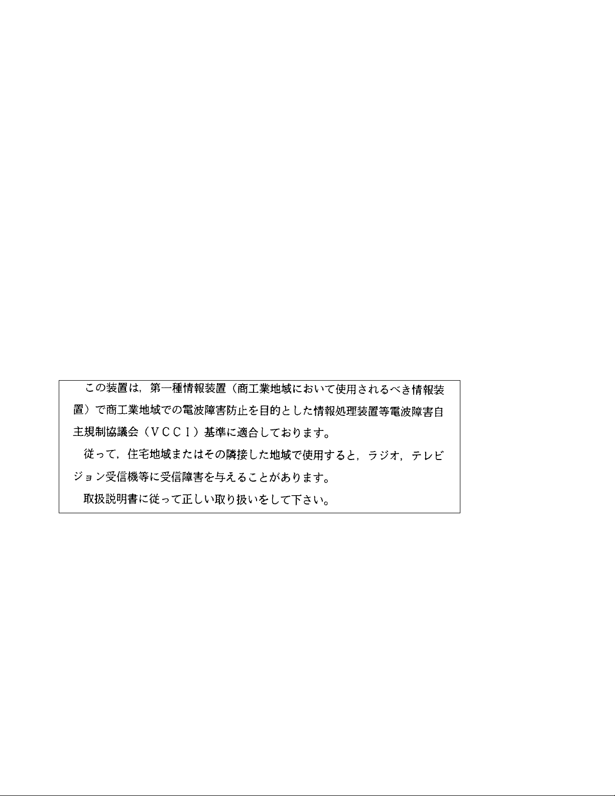
ATM Backplane
All data transmitted between modules in the ATM subsystem passes through the ATM
backplane. Data is switched between ATM media modules in the ATM subsystem by a
6416SW module. 6416SW modules are installed in slot positions 9 and 10 in the ATM
backplane of 10-slot models, and slot positions 9 and 10 and/or 11 and 12 in the ATM
backplane of 17-slot models. These positions are shown in Figure 1-1.
Fan Area
17
ATM
Backplane
ShuntBus
Ring-Bus
Connectors
Media
Backplane
TriChannel
TriChannel
Connectors
112233445566778899101011111212131314141515161617
Power
Module
Power
Module
Power
Module
Power
Module
Controller 2
Controller 1
ac Inlets
Figure 1-1. ATM Backplane in the 17-slot 3Com ONcore Hub
Two 6416SW modules may be installed in the 17-slot models. This allows for 6416SW
redundancy (see page “ATM Switch/Control Redundancy” on page 1-13).
1-3
Page 30
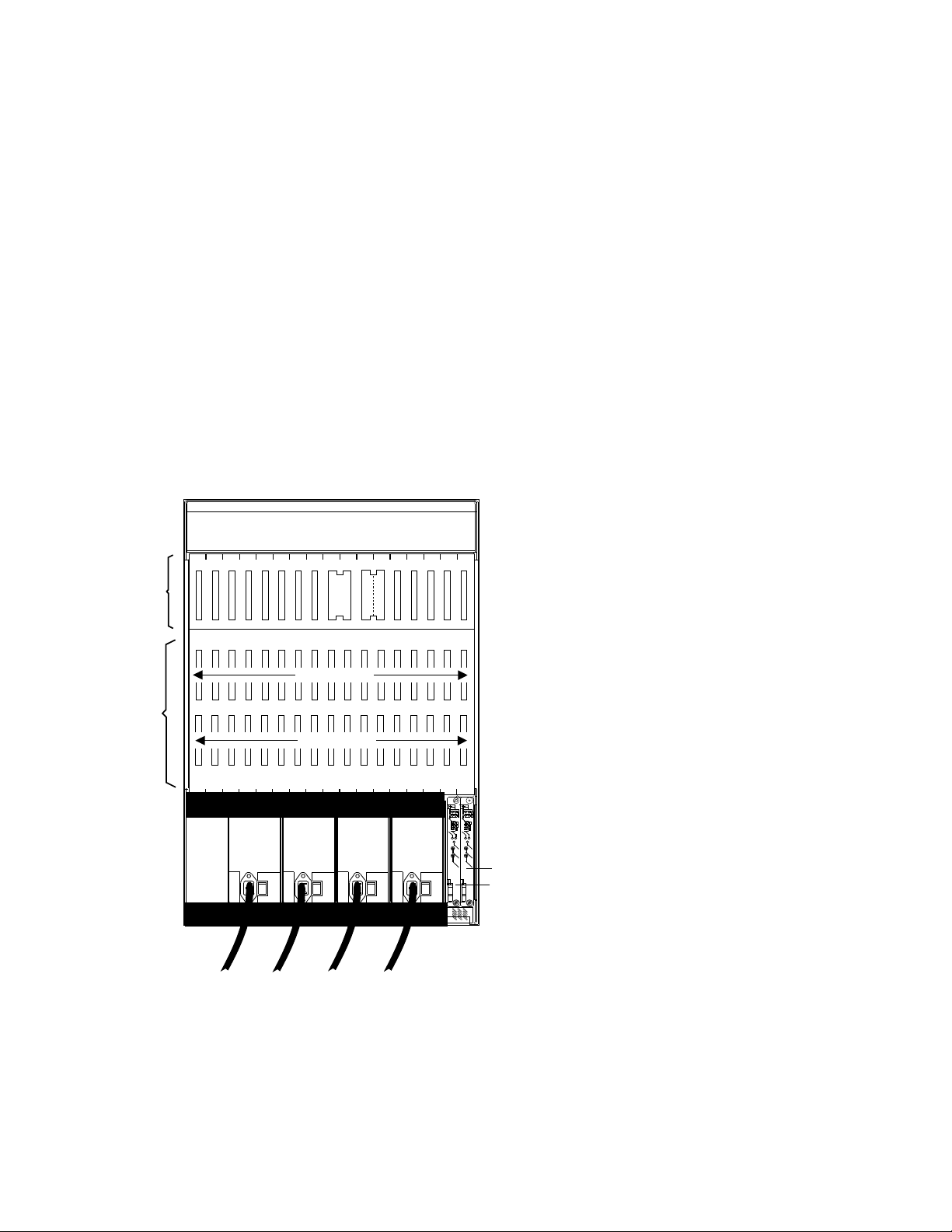
The major difference between the ATM backplane and other ONcore hub LAN
backplanes is that each ATM media module has a dedicated set of connections to the
6416SW module. This set of dedicated connections constitutes a wiring star topology in
which ATM media modules are at the tips of the star and the 6416SW module is at the
center. The wiring topology used in the ATM backplane is shown in Figure 1-2.
Slot Positions for
Fan Area
1 2 3 4 5 6 7 8 9 10 1112 13 14 15 16 17
6416SW Modules:
9 to 10 and 11 to 12
Slot Positions for
ATM Media Modules:
1 to 8 and 12 to 17
ATM Bus Linking
6416SW Modules
6416SW = ATM Switch/Control
Figure 1-2. Wiring Star Topology in ATM Backplane (17-slot model)
1-4 ONcore ATM Switch/Control Module: Installation and User's Guide
Page 31

The main characteristics of the ATM backplane are as follows:
Modular structure
Full floating ATM media modules
Support of two 6416SW modules for reliability and redundancy (in 17-slot models)
Full coexistence with existing legacy LAN modules.
ATM media modules can be hot-swapped into any open slot. Also, you can remove an
ATM module and re-insert it into another slot without disturbing the operation of other
ATM modules and without causing a failure in ATM connections in the hub.
You can install an ATM media module in any one of slots 1 to 8 in a 10-slot model, and
of slots 1 to 8 and 12 to 17 in a 17-slot model. Slots 9, 10, and 11 (in 17-slot models)
are reserved for 6416SW modules. After installing the module, you must configure it for
operation by entering a series of commands from the 6416SW local console or from a
TELNET session. The commands are detailed in the
Hub/CELLplex 4000 Workgroup Switch, ATM Command Reference Guide
SA33-0385 (hereafter referred to as the
Command Reference Guide
).
ONcore Switching Hub/CELLplex 4000 ATM
3Com ONcore Switching
17-00866,
1-5
Page 32

ATM Switch/Control Module
The ATM Switch/Contol Module (6416SW) module used in the ONcore hub consists of
two cards packaged into a double-slot module:
A base card (ATM Switch fabric) that switches cells from one ATM port to another
ATM port or to another output link on the same module.
ATM cell switching is carried out by means of the Switch integrated circuit, a
technology used by the ONcore switch. This single chip is a non-blocking 16-by-16
times 256 Mbps 8-bit parallel switch.
The Control Point card houses a processor where the Control program resides.
The 3Com ONcore ATM subsystem (as all ATM switching devices) requires a control
program to perform the functions associated with the establishment and management of
ATM circuits. These functions are integrated into the switching element of each
6416SW module. This allows the ONcore ATM subsystem to use a distributed control
system with the following advantages:
Each ATM module benefits from the fault-tolerant design of the 3Com ONcore
chassis.
Continued ATM network operation is ensured in case of a failure at a single point in
the network.
1-6 ONcore ATM Switch/Control Module: Installation and User's Guide
Page 33

The 3Com ONcore Switch imbedded Control Point provides a complete set of functions
to control an ATM campus network and to interconnect local ATM networks over ATM
wide area networks.
The Control Point supports an extensive set of ATM connections, including:
Switched (SVC) and permanent (PVC)
Point-to-point and point-to-multipoint
Reserved Bandwidth (RB) and Available Bit Rate (ABR)
Note: The Available Bit Rate service will be available in future releases of the 6416SW
module.
Table 1-1. ATM Connections Supported in ONcore Hubs
Type of Virtual
Connection
Virtual Path Connection
(VP)
Virtual Channel
Connection (VC)
Virtual Channel
Connection (VC)
ATM control functions are fully distributed instead of being centralized. This means that
all nodes participate as peers in the control algorithms. Due to the distribution of control
functions, ONcore ATM networks provide for availability, scalability, and growth.
Connection
Type
Permanent Reserved
Switched Reserved
Permanent Reserved
Connection Class Connection Mode
Bandwidth and
Available Bit Rate
Bandwidth and
Available Bit Rate
Bandwidth and
Available Bit Rate
Point-to-point
Point-to-point and
point-to-multipoint
Point-to-point
1-7
Page 34

Each 3Com ONcore Switch/Control provides the following functions:
Control plane:
– Support of ATM signaling (SVCs) according to ATM Forum V3.0 and V3.1
specifications.
– Switch-to-switch interface (SSI) based on an extension of the ATM Forum UNI
V3.0 as stated in the ATM Forum P-NNI framework
– Topology services and route computation based on TRS, with automatic bypass
of failed nodes and links only for SSI connections (TRS is an extension of
OSPF, Open Shortest Path First.)
– Interconnection of local ATM networks over an ATM WAN that provides a
permanent virtual path, allowing switched connections to be set up between end
systems on both sides of the WAN (VP tunneling)
– Internal SVC APIs to support node management and services over switched
ATM connections
– Support of permanent virtual path (VP) and permanent virtual channel (VC)
point-to-point connections
– Support of IP over ATM (RFC 1577) for node management and services
(Classical IP); PING message: 916 bytes maximum.
– Support of 802.3 LAN Emulation Client for node management and services
(LAN emulation). PING and TELNET messages: maximum length depends on
the maximum SDU size supported on the corresponding emulated LAN. See
Table 1-2 on page 1-15
1-8 ONcore ATM Switch/Control Module: Installation and User's Guide
Page 35

Management plane:
– Full SNMP support (get, getnext, set, and traps)
– MIB-II support
– IETF AToMIB
– Full Interim Local Management Interface (ILMI) support at UNI and from the
network management station
– OSPF MIB support for managing topology and route computation
– 3Com extension
— Hub-specific: switch, modules and ports
— Enhanced PVC management (automatic route computation and recovery)
— Signalling (Q.2931 and SAAL) configurations and statistics
— ATM statistics
– Services for local and remote administration.
User Plane (hardware):
– ATM layer (switching)
– Support of Reserved Bandwidth (RB) connection.
1-9
Page 36

The SNMP ATM agent is a function of the Control program in the 6416SW module and
implements the ATM MIB defined in the V3.0 UNI Specification of the ATM Forum.
The AToMIB is defined by the IETF and by the 3Com extensions. It can be driven by
SNMP managers, such as IBM NetView for AIX . The 3Com ATM management
application, Transcend ONcore ATM Campus Manager, can be used by a LAN
administrator to better tune the system.
Both PVCs and SVCs are supported. The signaling is upwardly compatible with the
ATM Forum V3.0 and V3.1 UNI. Control messages are encapsulated in the SAAL
Adaptation Layer.
The ILMI (ATM Forum V3.0) is fully supported. End-systems can register their local
address to the ONcore hub and receive notification of their network address. ILMI
messages are SNMP-formatted and conveyed using the AAL5 Adaptation layer.
1-10 ONcore ATM Switch/Control Module: Installation and User's Guide
Page 37

ATM Subsystem Traffic Management
High-speed ATM networks support a variety of applications with different traffic and
quality of service (QOS) requirements. For example, multimedia and time critical data
applications require guaranteed levels of delay and throughput, while other applications
can tolerate variations in delay and throughput (LAN traffic). This diversity requires
different congestion management methods.
The 3Com ONcore ATM subsystem supports the ATM Reserved Bandwidth (RB)
service type of traffic.
In the Reserved Bandwidth (RB) service, an application needs to establish a traffic
contract with the network before transmitting data. The traffic contract consists of a
specified QOS class and a set of traffic descriptors. Through resource allocation, the
network either provides the desired QOS for the ATM connection or refuses the call.
For this method, the source must be accurately modelled and able to precisely describe
its traffic pattern. The allocated bandwidth is usually less than the peak rate in order to
benefit from statistical multiplexing gains which may cause congestion. A source
policing scheme ensures that the source conforms itself to the contract by means of a
"leaky bucket" rate control.
The use of selective and global backpressure for traffic management in the ATM
subsystem gives the 3Com ONcore ATM network an added value. Selective
backpressure temporarily stops one virtual connection. Global backpressure
temporarily stops an ATM link.
1-11
Page 38

ATM Subsystem Chassis Management
Management of the ATM subsystem can be achieved in two ways:
Via a Distributed Management Module (DMM) installed in the ONcore hub.
Via the 6416SW module, which contains a subset of DMM, when the ONcore hub is
only running ATM. (Check the Release Notes for the level of 6416SW code
required).
Note: If a DMM module is present, or hot-inserted, in the hub, the DMM module will
assume chassis management, and 6416SW commands entered will not be effected.
The required commands, in this case, should be entered from a DMM console, and not
the local console.
Power management of the hub is provided by the SET POWER MODE and SHOW
POWER commands. The power mode can be set so that if an additional power supply
is available, the supply is kept in reserve, to be used in the event of failure. Power
management information can be displayed to show the amount of power available, and
the amount of power consumed by the hub. In addition, the power budget, power
modes, and power information can be displayed for individual slots.
A complete inventory of the hub's contents, including fans and power supplies can be
displayed via the SHOW HUB command.
The SHOW INVENTORY command allows you to display inventory information about
the hub, including all modules, submodules, and controller module.
For more information, see the
Reference Guide
.
ONcore Switching Hub/CELLplex 4000 ATM Command
1-12 ONcore ATM Switch/Control Module: Installation and User's Guide
Page 39

ATM Switch/Control Redundancy
By installing a second 6416SW in a 17-slot hub, a backup to the active 6416SW is
provided (check the Release Notes for the level of 6416SW and the level of code
required). If the active 6416SW fails, the standby will take over control. The active
6416SW continually updates the tables in the standby 6416SW to ensure that the
backup configuration is current, and to reduce the impact should a switch to the standby
be required. The active 6416SW checks every one second to determine if the standby
6416SW is present and up-to-date. The date and time are also updated to ensure
network time consistency in case of switch-over.
The active 6416SW also periodically requests that the standby 6416SW perform
diagnostics to ensure that it is capable of assuming control if required.
Which 6416SW is to be active can be defined by the operator in both Maintenance and
Administrator modes, via the SET ROLE or SET DEVICE ROLE command (see the
ONcore Switching Hub/CELLplex 4000 ATM Command Reference Guide
This choice is considered at next reset when electing the active 6416SW. Maintenance
mode can be entered for the backup 6416SW, but this mode will be ended should the
active 6416SW fail or enter Maintenance mode.
for details).
Note: The standby 6416SW does not support Telnet. There are two console modes
available, basic dialog mode and maintenance mode.
1-13
Page 40

Benefits of Using ATM in the ONcore Hub
The use of ATM in the ONcore hub offers the following benefits:
Use of ATM in local and wide area networks, and in both private and public
networks
ATM support for multimedia applications and mixed traffic, such as voice, video,
and data
Extension of current application solutions by providing bandwidth on demand and
allowing applications to share bandwidth
Support for current and future high-bandwidth applications and protocols
Low transfer delay and support for both non-realtime and realtime applications by
providing large peak bandwidth
Coexistence of ATM with the existing LAN backplane allowing for the combined use
of shared media LANs and ATM
Integration of ATM into the ONcore hub management functions
Distributed switching across ONcore hubs for greater network reliability
Platform for providing ATM to the desktop and high media concentration
Independent of physical interface type
Simplified networking and architecture.
1-14 ONcore ATM Switch/Control Module: Installation and User's Guide
Page 41

LAN Emulation Client (LEC)
The 6416SW contains an integrated ‘lite’ LEC that provides basic LAN emulation client
functions for use by an SNMP agent or for Internet FTP functions. Such functions
include Netview, TELNET, and TFTP. The LEC implementation is fully ATM Forum
compliant.
The maximum length of PING and TELNET messages depends on the maximum SDU
size supported on the corresponding emulated LAN. Table 1-2 lists the correspondence
(in bytes):
Table 1-2. Maximum PING and TELNET Message Lengths
802.3 ELAN max SDU PING/TELNET maximum length
1516 1492
4544 4520
9234 9210
18190 18166
If a connection is lost between a LEC and a LAN emulation server (LES), the LEC will
attempt to reconnect 5 times, at intervals of 5 seconds. If the connection is not
re-established, the LEC will continue attempts to reconnect, at intervals of one minute.
1-15
Page 42

1-16 ONcore ATM Switch/Control Module: Installation and User's Guide
Page 43

Chapter 2. Installation
This chapter describes how to install the 6416SW module. Before you unpack the
module, please follow the precautions in “Before You Start.”
Before You Start
Take the following precautions before unpacking the 6416SW module:
Do not remove the 6416SW module from its anti-static shielding bag until you are
ready to insert it into the ONcore hub. This avoids the possibility of having
electrostatic discharge damage static-sensitive devices in the 6416SW cards.
Always use a foot strap and grounded mat or wear a grounded static discharge
wrist strap whenever you inspect or install the 6416SW module. Or else, touch a
grounded rack or another source of ground before handling the 6416SW module.
Verify that the 6416SW module is the correct feature by matching the part number
listed on the side of the shipping carton to the part number you ordered.
2-1
Page 44

Unpacking the Module
To unpack the 6416SW module, follow these steps:
1. Remove the 6416SW module from the shipping carton.
2. Remove the 6416SW module from the anti-static bag and inspect it for damage.
Always handle the module by the faceplate being careful not to touch the internal
components.
If the module appears damaged, put it back in the anti-static bag, and put the bag
back into the shipping carton. Then contact your local 3Com dealer or 3Com
representative.
3Com suggests that you keep the shipping carton and the anti-static shielding bag
which your 6416SW module was delivered in, in case you later want to repackage the
module for storage or shipment.
3Com also suggests that you record the serial number of your 6416SW module and
other information about the modules in your ONcore hub in the Hub Planning Chart
provided in your ONcore Switching Hub Reference Library.
2-2 ONcore ATM Switch/Control Module: Installation and User's Guide
Page 45

Installing the 6416SW Module
To install a 6416SW module in the ONcore hub, follow these steps:
1. Install the ONcore hub in its rack or on a desktop by following the instructions in the
3Com ONcore Hub Installation Guide
2. Insert the 6416SW module into slots 9 and 10 (or slots 11 and 12 in A17 models) of
the hub by matching the top and bottom board guides as you slide the module
cleanly into place (by pressing evenly on the top and bottom of the faceplate). Do
not attempt to push the module all the way into the hub until you have verified that
the top and bottom module ejectors are OPEN (see Figure 2-2 on page 2-4.)
3. Make sure that the module is plugged into the connectors on the ATM backplane.
(17-00362).
1234567
Slots
ACTIVE
ERROR
RUNNING
STBY
MAINT
RESET
ATM
RESET
RS-232
CONSOLE
RS-232
AUXILIARY
WRONG
SLOT
A-SCPSW
8910
1
2
3
4
ACTIVITY
STAT
RESET
MODULE
RESET
PO RT1
PO RT2
PO RT3
PO RT4
11121314
1516
17
1
2
3
4
ACTIVITY
STAT
RESET
MODULE
RESET
PO RT1
PO RT2
PO RT3
PO RT4
Figure 2-1. Installing the 6416SW Module in an ONcore Hub
2-3
Page 46

4. Close the top and bottom ejectors simultaneously.
Figure 2-2. ONcore Module Ejectors
2-4 ONcore ATM Switch/Control Module: Installation and User's Guide
Page 47

5. Fasten the spring-loaded screws on the front panel of the module to the hub using
your fingers. Do not over-tighten.
6. (optional) Press the LED Test button on the Controller module to verify that all
LEDs are functional.
7. If you want to use a local console to configure (out-of-band) the ATM subsystem,
you must attach an ASCII-type terminal to the RS-232 Console port on the 6416SW
module. The connection can either be local or via modems.
If you use the modem cables that are delivered with the ONcore hub, you must also
use the null modem adapter supplied with the 6416SW module.
Verify that the console and modems (if used) meet the factory defaults of the
6416SW module. If they are not compatible with the factory defaults, you will not
be able to communicate with the module. The default 6416SW settings are:
9600 baud rate
8 data bits
No parity
1 stop bit.
See Chapter 4, “Setting-Up and Using a Configuration Console” on page 4-1 for
more information.
8. Attach one end of an RS-232 cable to the RS-232 Console port, the topmost
RS-232 port on the front panel of the 6416SW module. Loop the cable through the
hub cable tray (if installed) and attach the other end to the RS-232 serial port
connector on the console or personal computer.
Note: The RS-232 cable can be a maximum of 200 feet (61 meters) in length.
There are several RS-232 cable configurations available. Refer to Appendix B,
“RS-232 Cable and Modem Requirements” on page B-1 for more information on the
exact RS-232 cable that you need.
2-5
Page 48

1
2
3
4
ACTIVITY
STAT
RESET
MODULE
RESET
PORT 1
PORT 2
PORT 3
PORT 4
RS-232 Console port
1
2
3
4
ACTIVITY
STAT
RESET
MODULE
RESET
PORT 1
PORT 2
PORT 3
PORT 4
Figure 2-3. Attaching a Terminal to the 6416SW RS-232 Console Port
9. Attach cables to the ATM media modules and ATM user devices you want to use.
Then enter 6416SW commands from the console (as described in Chapter 5,
“Configuring the ATM Switch/Control Module” on page 5-1) to configure the ATM
subsystem.
10. Enter the SAVE ALL command from the console once you have configured all ATM
media modules. The 6416SW module saves the configuration information in
nonvolatile memory.
2-6 ONcore ATM Switch/Control Module: Installation and User's Guide
Page 49

Verifying Normal 6416SW Operation
After installing the 6416SW module, you can verify that it is operating properly by
checking the status of the LEDs and the message displayed on the console screen.
The position of the LEDs is shown in Figure 2-4 on page 2-9.
The RUNNING LED on the module should light (yellow).
The ACTIVE LED should light (yellow) if the 6416SW module is managing ATM
media modules.
The WRONG SLOT LED should not light.
If the module is installed properly and if the RS-232 connection is made, the
following message should display on the console screen when you press Enter:
ATM Switch/Control Module
(c) Copyright IBM Corp. 1994, 1996. All rights reserved.
Now you can enter 6416SW commands from the local console to set up your system
defaults and configure ATM media modules as explained in Chapter 5, “Configuring the
ATM Switch/Control Module” on page 5-1. If you have problems while configuring your
ATM subsystem, refer to Chapter 7, “Troubleshooting” on page 7-1.
How to perform wrap tests on ATM ports is described in the
Hub/CELLplex 4000 ATM Command Reference Guide
The next section describes the front panel of the 6416SW module and the meaning of
each LED.
ONcore Switching
.
2-7
Page 50

Front Panel
The front panel of the 6416SW module contains:
Seven LEDs that show the operating state of the module
9-pin RS-232 Console port
9-pin RS-232 Auxiliary port (reserved for 3Com service personnel)
ATM Reset button that resets all ATM modules (6416SW and ATM media) in the
ONcore hub.
The position of these components on the front panel is shown in Figure 2-4 on
page 2-9
2-8 ONcore ATM Switch/Control Module: Installation and User's Guide
Page 51

Active LED
Standby LED
Maintenance LED
Reset LED
ATM Reset button
(resets all ATM
modules and
ATM traffic)
RESET
ACTIVE
MAINT
RESET
Running LED
ERROR
RUNNING
STBY
ATM
RS-232
CONSOLE
Error LED
RS-232
Console Port
RS-232
AUXILIARY
RS-232
Auxiliary Port
Wrong Slot LED
WRONG
SLOT
Figure 2-4. Front Panel of 6416SW Module
2-9
Page 52

Meaning of the LEDs
Table 2-1 shows the meaning of each LED on the front panel of the 6416SW module.
Table 2-1 (Page 1 of 2). Meaning of the 6416SW LEDs
LED Name Color State Meaning
Active Yellow OFF 6416SW module is not able to
control ATM traffic and ATM
media modules.
ON 6416SW module is able to
control ATM traffic and ATM
media modules.
Standby
(STBY)
Running Yellow OFF 6416SW software is not running.
Error Red OFF 6416SW module is functioning
Yellow OFF Either a second 6416SW module
is not installed or, if a second
6416SW is installed, it is not
active.
ON The second 6416SW module is
installed and active.
The Error LED or the
Maintenance LED lights up.
ON 6416SW software is started and
running properly.
properly.
ON 6416SW module is not
operational because of an error.
See Chapter 7,
“Troubleshooting” on page 7-1.
2-10 ONcore ATM Switch/Control Module: Installation and User's Guide
Page 53

Table 2-1 (Page 2 of 2). Meaning of the 6416SW LEDs
LED Name Color State Meaning
Maintenance
(MAINT)
Reset Yellow OFF 6416SW module is functioning
Wrong Slot Yellow OFF Normal operation.
Yellow OFF 6416SW module is functioning
properly.
ON Maintenance mode is active.
properly.
ON 6416SW and ATM media
modules in hub are being reset.
ON 6416SW module is not installed
in the correct slots.
2-11
Page 54

ATM Reset Button
The ATM Reset button resets the 6416SW and all ATM media modules in the ONcore
hub. All data traffic and connections in the ATM subsystem are stopped.
Press this button when instructed after you correct an error condition. Before pressing
it, be sure to save any configuration settings entered in the current session with the
SAVE command. When you press the ATM Reset button, all unsaved settings will be
lost.
The button is recessed on the front panel to prevent it from being accidentally pressed.
To press it, use a pen or a small screwdriver to hold the button down.
Pressing the ATM Reset button has the same effect as entering the RESET
ATM_SUBSYSTEM FORCE command from the 6416SW console.
2-12 ONcore ATM Switch/Control Module: Installation and User's Guide
Page 55

RS-232 Console Port
The 9-pin RS-232 Console port (the topmost RS-232 port on the front panel) is a DTE
male connector (DB-9) to which a console or modem is connected in order to:
Initialize the 6416SW module at installation.
Enter 6416SW network management commands (described in the
Switching Hub/CELLplex 4000 ATM Command Reference Guide
Download new software versions.
Table 2-2. RS-232 Console Port Pin Assignments (DB9)
Pin Number Signal Name
1 Carrier Detect (CD)
2 Receive Data (RX)
3 Transmit Data (TX)
4 Data Terminal Ready (DTR)
5 Signal Ground (GND)
6 Data Set Ready (DSR)
7 Request to Send (RTS)
8 Clear to Send (CTS)
ONcore
).
9 No connection
An RTS signal is not continuously sent by the 6416SW module. If you attach a terminal
(such as an IBM 3151 or 3164) you should configure it with IPRTS (Induced Permanent
RTS) for Line Control.
2-13
Page 56

RS-232 Auxiliary Port
The 9-pin RS-232 Auxiliary serial port (the bottommost RS-232 port on the front panel)
is also a DTE male connector (DB-9).
The RS-232 Auxiliary port is reserved for 3Com service engineers. No device
should be connected to it during normal hub operation.
Table 2-3. RS-232 Auxiliary Port Pin Assignments
Pin Number Signal Name
1 No connection
2 Receive Data (RX)
3 Transmit Data (TX)
4 No connection
5 Signal Ground (GND)
6 No connection
7 Request to Send (RTS)
8 Clear to Send (CTS)
9 No connection
2-14 ONcore ATM Switch/Control Module: Installation and User's Guide
Page 57

Chapter 3. ATM
Addressing
This chapter describes:
The components of an ATM Campus Network
Guidelines for defining an ATM Address for the ATM Switch/Control
How to set up trunk connections within and between subnetworks
How to use Permanent Virtual Connections (PVCs).
ATM Campus Networks
The purpose of an ATM network is to set up connections between ATM user devices,
the two endpoints of a connection.
3Com ATM subsystems can be interconnected in order to build a local, privately owned
and administered ATM network called an ATM Campus Network.
3-1
Page 58

Figure 3-1. Components of an ATM Campus Network
3-2 ONcore ATM Switch/Control Module: Installation and User's Guide
Page 59

Network Components
The various parts of the ATM address form a hierarchy of network components, as
shown in Figure 3-2.
Figure 3-2. ATM Address Hierarchy
For a full description of the ATM address formats supported by the 6416SW, see
Appendix E, “ONcore ATM Address Formats” on page E-1.
The terms used to describe the components of an ATM Campus Network are defined
here:
ATM Campus Network
One or more ATM subnetworks interconnected using NNI
interfaces.
This set of subnetworks is controlled by one administrative domain
and a single private owner using one network access protocol
(UNI).
An ATM Campus Network is identified by:
The first 9 bytes of the unique network prefix.
3-3
Page 60

ATM Subnetwork One or more ATM clusters interconnected using NNI interfaces.
An ATM subnetwork is identified by:
The first 9 bytes of the network prefix, which are the same for
all subnetworks in a Campus Network, plus
A 2-byte routing domain number (RDN), which is unique within
the ATM Campus Network.
ATM Cluster One or more ATM subsystems interconnected using SSI interfaces.
An ATM Cluster is identified by:
The first 11 bytes of the network prefix, which are the same for
all clusters in an ATM subnetwork, plus
A 1-byte ATM Cluster Number (ACN), unique within the ATM
subnetwork, which ranges from 0 to 255.
ATM Subsystem The components of the ATM subsystem in the hub include:
Integrated ATM Switch/Control module functions
Devices connected to the ATM ports
ATM media modules installed
ATM interfaces: user-to-network (UNI), switch-to-switch (SSI),
network-to-network (NNI).
An ATM Subsystem is identified by:
The first 12 bytes of the network prefix, which are the same for
all subsystems in a cluster, plus
A 1-byte Hub Number (HN), unique within the ATM Cluster,
which ranges from 0 to 255.
ATM User Device An end system that encapsulates data into ATM cells and forwards
them to the ATM subsystem across a UNI interface. Examples of
ATM user devices are:
Servers and workstations equipped with ATM adapters
ATM concentrators or workstations equipped with ATM adapters
Routers with ATM adapters
LAN ATM bridges.
3-4 ONcore ATM Switch/Control Module: Installation and User's Guide
Page 61

An ATM User Device is identified by:
The first 13 bytes of the network prefix, which are the same for
all user devices attached to an ATM subsystem, plus
A 6-byte End System Identifier (ESI), unique within the ATM
Subsystem, plus
A 1-byte Selector field that may be used by the user device.
The 6416SW passes the network prefix of an ATM address to
attached end systems using the Interim Local Management
Interface (ILMI) protocol.
3-5
Page 62

Network Interfaces
ATM standards define three protocols used across the interfaces connecting the
components of an ATM campus network:
UNI Defines the interface between an ATM User Device (such as a terminal,
router, bridge, server, workstation, or concentrator equipped with an ATM
adapter) and the ATM network. The ATM subsystem supports the private
UNI defined by the ATM Forum UNI Specification V3.1.
SSI Defines the interface between two ATM switches in the same ATM Cluster.
The SSI fully supports networking functions without the need of operator
intervention, such as routing, node failure and node recovery, backup, and
topology management by the Topology Routing Service (TRS) program.
You can define multiple SSI connections between two ATM switches. The
SSI has been developed from the Public-NNI for use in 3Com ATM
subnetworks.
NNI Defines the interface between two ATM switches belonging to different ATM
Clusters in the same subnetwork or in different subnetworks.
Operator intervention is required in order to manage networking functions
such as routing, backup, topology changes, and so on.
You can define only one NNI connection between two ATM switches.
3-6 ONcore ATM Switch/Control Module: Installation and User's Guide
Page 63

Defining the ATM Address of the 6416SW
A default ATM address is provided with the 6416SW. You can continue to use this
default address only if you use your 6416SW as a stand-alone ATM switch.
If you want to connect the 6416SW to other ATM subsystems, the ATM address must
be defined as follows:
AFI-RDN The first (leftmost) 11 bytes of the Network Prefix is the address of the ATM
subnetwork to which this 6416SW belongs.
If the ATM campus network is connected to a public carrier, this address is
assigned by the appropriate administrative authority.
ACN If the ATM subnetwork contains multiple ATM clusters, this byte specifies the
number of the cluster to which this 6416SW belongs.
HN If the ATM cluster contains multiple ATM subsystems, this byte specifies the
number of this 6416SW in the cluster.
This address is assigned to the 6416SW using the SET DEVICE ATM_ADDRESS
command, which automatically saves the ATM address and resets the ATM subsystem.
3-7
Page 64

Setting-Up ATM Trunk Connections
To configure a trunk between two ATM subnetworks or two ATM clusters in the same
subnetwork over a virtual path (VP) service provider, you must configure a logical link
between a pair of ATM ports. The ATM ports must both use a network-to-network (NNI)
interface and be on the boundary hub of each subnetwork or cluster.
Figure 3-3 shows an example of logical links between pairs of ATM clusters from a
boundary hub in each cluster.
Figure 3-3. ATM Logical Links Used to Connect ATM Clusters
3-8 ONcore ATM Switch/Control Module: Installation and User's Guide
Page 65

You can configure multiple logical links over the same physical port. However, you can
only configure one logical link (using one pair of ATM ports) for each ATM
cluster-to-cluster or subnetwork-to-subnetwork connection.
Using Static Routes
In an ONcore/CELLplex 4000 ATM network, you can only set a logical link to a cluster
number (ACN) that is defined within your own ATM subnetwork. In order to set up a
logical link with a remote cluster outside your own subnetwork, you must use the SET
STATIC_ROUTE command to assign an ACN to the network prefix of the boundary hub
of each remote cluster to which you want to link. The SET LOGICAL_LINK command
then will be able to set up a connection to this logical hub using its assigned ACN.
Trunks Within a Single Cluster/Subnetwork
To define a logical link between switches within the same cluster or subnetwork, use the
SET LOGICAL_LINK command to set the following parameters for each port in each
switch:
Virtual Path Identifier (VPI) number
ATM cluster number (ACN) for the remote switch
Bandwidth available on the virtual path
Signalling role for Q.2931 protocol.
3-9
Page 66

Trunks Between Subnetworks
In order to define a logical link between switches in different subnetworks, you must
also use the SET STATIC_ROUTE command to associate the address of the boundary
hub in the remote cluster with a locally defined ACN.
The SET LOGICAL_LINK command then uses this ACN to establish the logical link with
the remote cluster.
3-10 ONcore ATM Switch/Control Module: Installation and User's Guide
Page 67

Example: Configuring a Connection Between User Devices
When configuring a connection between two ATM user devices attached to different
subnetworks (for example, between Workstation D and Workstation E in Figure 3-4 on
page 3-12), you must:
Configure the route between the clusters in the first subnetwork; for example,
between Clusters A and B in subnetwork Y.
Configure the route between the clusters in both subnetworks; for example, from
Cluster B in subnetwork Y to Cluster C in subnetwork X.
To configure the route from Workstation D to Workstation E, you would start from hub
F, the entry point to Cluster A in subnetwork Y:
1. From hub F, enter the SET STATIC_ROUTE command with the ACN for Cluster C.
2. From hub G (boundary hub), enter the SET LOGICAL_LINK command with the
ACN for Cluster C.
3. From hub H (the entry point in Cluster B), enter the SET STATIC_ROUTE
command with the ACN for Cluster C.
4. From hub H (which is also a boundary hub), enter the SET LOGICAL_LINK
command with the ACN for Cluster C.
The ATM address of Workstation E is known in Cluster C by the updates received
at each ATM switch by the Topology Routing Service (TRS).
To configure the route for communication in the opposite direction, from Workstation E
to Workstation D, you would start from Hub J, the entry point to Cluster C in subnetwork
X:
1. From hub J, enter the SET STATIC_ROUTE command with the ACN for Cluster A.
2. From hub I (boundary hub), enter the SET LOGICAL_LINK command with the ACN
for Cluster A.
3. From hub H (entry point), enter the SET STATIC_ROUTE command with the ACN
for Cluster A.
3-11
Page 68

4. From hub H (boundary hub), enter the SET LOGICAL_LINK command with the
ACN for Cluster A.
The ATM address of Workstation D is known in Cluster A by the TRS updates.
Figure 3-4. Using Static Route Mappings to Connect User Devices
Across Subnetworks
3-12 ONcore ATM Switch/Control Module: Installation and User's Guide
Page 69

Using Permanent Virtual Connections
Permanent virtual connections (PVCs) for virtual channel and virtual path connections
are created via the SET PVC command. See the
ATM Command Reference Guide
for details.
ONcore Switching Hub/CELLplex 4000
3-13
Page 70

3-14 ONcore ATM Switch/Control Module: Installation and User's Guide
Page 71

Chapter 4. Setting-Up and
Using a Configuration
Console
This chapter describes:
How to enter commands and get help on the 6416SW configuration console
How to set up the 6416SW configuration console in Normal (ASCII) mode
How to set up the 6416SW configuration console via a SLIP protocol connection
How to access the 6416SW from a remote console via TELNET
How to reconfigure configuration console settings.
Overview
The commands for configuring the 6416SW are entered using a configuration console
(ASCII terminal or workstation) connected to the console port. The console can
communicate in one of two ways:
Normal (ASCII) mode
In normal mode, commands are entered directly from the configuration
console.
See “Setting Up a Configuration Console in Normal (ASCII) Mode” on
page 4-7 for instructions on connecting a configuration console to the
6416SW in Normal mode.
4-1
Page 72

SLIP mode
In SLIP mode, commands are entered via a TELNET session between an IP
workstation and the 6416SW.
If your workstation supports TFTP, it can also be used as a TFTP server to
perform DOWNLOAD and UPLOAD operations between your workstation
and the ONcore. (See “Uploading and Downloading Operations” on
page 6-5.)
Note: If no activity takes place for a period of 20 minutes, the console is
automatically returned to normal mode.
This method requires an initial connection in Normal mode to set up the IP
addresses and change the port protocol.
See “Setting Up a Configuration Console in SLIP Mode” on page 4-8 for
instructions on connecting a configuration console to the 6416SW in SLIP
mode.
After the switch has been initially configured, it is also possible to configure and manage
the switch:
From a remote TELNET sessions, as described in “TELNET Sessions Via a
Remote Switch” on page 4-12.
Using an SNMP management application, as described in Chapter 6, “Network and
Switch Management” on page 6-1.
4-2 ONcore ATM Switch/Control Module: Installation and User's Guide
Page 73

Before You Start
The following section describes keystrokes and the command syntax to use to enter
6416SW commands from a configuration console. For a complete description of all
6416SW configuration commands, see the
Command Reference Guide
.
Entering 6416SW Commands
By entering commands at the prompt on the 6416SW configuration console, you can
configure various functions of the 6416SW. The management prompt appears as
follows:
@
ONcoreATM>
ONcore Switching Hub/CELLplex 4000 ATM
6416SW commands are not case-sensitive. The system interprets ABC (uppercase) the
same as abc (lowercase).
The values you enter for certain command parameters are, however, case-sensitive
and must be typed exactly as shown in the
Command Reference Guide
com_name parameter in two separate SET COMMUNITY commands, you will create two
different community names.
. For example, if you enter RWTRAP and rwtrap for the
ONcore Switching Hub/CELLplex 4000 ATM
4-3
Page 74

Keyboard Functions
When entering 6416SW commands the following keyboard functions are available:
Keystroke Function
BS or Backspace Moves the cursor one space backward and deletes the character.
Enter Runs the command or prompts you to enter missing parameters.
Space bar Types the complete 6416SW command.
Ctrl + C Cancels the command that is currently running and returns you to
a blank command line.
Ctrl + R Retypes the last command you entered on the command line.
The last 10 commands you entered can be retyped in this way.
Ctrl + L Types the currently edited command on the next line.
? Displays a list of available commands.
4-4 ONcore ATM Switch/Control Module: Installation and User's Guide
Page 75

Getting Help
To get help on available 6416SW commands, type ? on the command line and press
Enter. For example, to see what commands start with the word SAVE, you would enter:
@
ONcoreATM> save ? [ENTER]
The following response is displayed:
@
Possible completions:
alert
all
community
device
lan_emul
module_port
static_route
terminal
tftp
If you logged on as the system administrator, you can enter ? to display a list of all
active 6416SW commands. An example is shown here:
@
ONcoreATM> ? [ENTER]
clear
download
dump
logout
maintain
ping
reset
revert
save
set
swap
telnet
upload
wrap
4-5
Page 76

Command Completion
The 6416SW management command line accepts abbreviated command input with a
facility called command completion. Command completion lets you enter a command
and its parameters by typing the minimum number of characters to uniquely identify the
command or a parameter.
For example, to enter the SAVE command, you only need to type SA and press the
space bar:
@
ONcoreATM> sa
The system automatically fills in the rest of the command:
@
ONcoreATM> save
To enter a parameter, such as COMMUNITY, with the SAVE command, you can type the
first few letters (for example, COMM) and press the space bar:
@
ONcoreATM> save comm
The rest of the parameter is automatically entered:
@
ONcoreATM> save community
If you enter an insufficient number of letters (for example, only S or C) for the system to
determine the command or parameter (for example, Set, Show, Save and so on), the
word is not completed and you are prompted to enter the rest of the command. The
system also prompts you if you forget to enter a mandatory parameter.
4-6 ONcore ATM Switch/Control Module: Installation and User's Guide
Page 77

Setting Up a Configuration Console in Normal
(ASCII) Mode
The following procedure sets up the configuration console in Normal mode and logs you
on as the system administrator with full access to all 6416SW commands:
1. Connect an ASCII-type terminal to the RS-232 console port on the front panel of the
6416SW.
2. In the terminal’s user guide, locate the procedure for setting parameters for baud
rate, data bits, parity, and stop bits.
3. Configure these configuration console settings to the values used by the 6416SW
so that the configuration console and the 6416SW can communicate. The
factory-set default settings for the 6416SW are as follows:
Baud rate 9600
Data bits 8
Parity None
Stop bits 1
4. Press Enter. The following message is displayed:
@
ATM Switch/Control Module
(c) Copyright IBM Corp. 1994, 1996. All rights reserved.
Password:
5. As no factory password is provided for administration first Logon, press Enter.
@
Welcome to system administrator service on ONcore.
ONcoreATM>
You can now proceed to configure the 6416SW, as described in Chapter 5,
“Configuring the ATM Switch/Control Module” on page 5-1.
4-7
Page 78

Setting Up a Configuration Console in SLIP Mode
The procedure that follows sets up the configuration console in SLIP mode and logs you
on as the system administrator with full access to all 6416SW commands.
Note: A typical workstation includes two serial ports (COM1, COM2):
One dedicated to an ASCII-terminal emulator,
The other dedicated to an IP stack and supported via the SLIP protocol.
Both ports are needed for this procedure.
1. Connect your workstation to the RS-232 console port on the front panel of the
6416SW from the ‘ASCII-terminal’ serial port.
2. Configure the terminal in Normal mode and logon as administrator as described in
“Setting Up a Configuration Console in Normal (ASCII) Mode” on page 4-7.
3. If a data transmission rate other than 9600 is required, use the SET TERMINAL
BAUD command to configure a data transmission rate.
@
ONcoreATM> set terminal baud 192 [ENTER]
4. Set the local IP address (6416SW) and remote IP address (workstation) for the
SLIP protocol using the SET TERMINAL SLIP_ADDRESSES command.
@
ONcoreATM> set terminal slip_addresses [ENTER]
Enter local ip address : 9.1 .86.139 [ENTER]
Enter remote ip address : 9.1 .86.138 [ENTER]
ONcoreATM>
5. Switch the configuration console port operating mode to SLIP using the SET
TERMINAL CONSOLE_PORT_PROTOCOL command.
@
ONcoreATM> set terminal console_port_protocol slip [ENTER]
6. Unplug the cable from the ‘ASCII-terminal’ serial port and plug it into the ‘IP-stack’
serial port of your workstation.
4-8 ONcore ATM Switch/Control Module: Installation and User's Guide
Page 79

7. Configure the IP stack SLIP with the IP address of the 6416SW and verify the
6416SW-to-workstation connectivity by issuing a PING request.
@
C:\ping 9.1 .86.138 [ENTER]
8. Start a TELNET session to the 6416SW.
@
ONcoreATM> telnet 9.1 .86.139 [ENTER]
9. Logon as administrator. The Welcome screen is displayed:
@
Password:
Welcome to system administrator service on ONcore.
ONcoreATM>
You can now proceed to configure the 6416SW, as described in Chapter 5,
“Configuring the ATM Switch/Control Module” on page 5-1.
Returning to Normal Mode
To switch the configuration console port back to Normal mode, use the SET TERMINAL
CONSOLE_PORT_PROTOCOL command.
@
ONcoreATM> set terminal console_port_protocol normal [ENTER]
Note: An 6416SW RESET restores the configuration console port to NORMAL
operating mode.
4-9
Page 80

SLIP Support
The SLIP function is supported on:
TCP/IP for AIX version 3.2.5
TCP/IP V2.1.2 for IBM DOS V7 (no TFTP support)
TCP/IP V2.0 for OS/2 V3 (WARP)
ChameleonNFS V4.0 for Windows
Using TCP/IP for AIX version 3.2.5
1. Enter smitty mkinet
2. Enter serial line INTERNET Network Interface
3. Configure the local and remote IP addresses
4. The mask is not required
5. Do not fill in the baud rate and the dial string
6. PING the IP address of the remote 6416SW.
Using TCP/IP V2.1.2 for IBM DOS V7 (no TFTP support)
1. Use Custom command, then SLIP interface
2. Select SL and enable the interface
3. Select COM1 and 9600 modem speed
4. Configure the local and remote IP addresses
5. The mask is not required
6. PING the IP address of the remote 6416SW.
4-10 ONcore ATM Switch/Control Module: Installation and User's Guide
Page 81

Using TCP/IP V2.0 for OS/2 V3 (WARP)
1. Configure the SLIP connection using the TCPIPCFG icon then SLIP.
2. Enable the SLIP interface on the correct COMM port.
3. Keep VJ compression off and use 1000 as MTU size.
4. Configure the local and remote IP addresses.
5. The mask is not required.
6. Configure FTFP server using TCPIPCFG icon thru
in the FTFP server for 6416SW download and upload operations.
7. Set terminal speed with the mode com1 command.
8. PING the IP address of the remote 6416SW.
AUTOSTART
. This is required
Using ChameleonNFS V4.0 or V4.1 for Windows
1. Configure the SLIP connection using the Custom icon under ChameleonNFS
2. Select COM1 and no flow control PORT option
3. Do not select a modem under the Modem option
4. Configure the local and remote IP addresses
5. The mask is not required.
6. Enter the appropriate hostname in the services/host table.
7. Use the TELNET icon under ChameleonNFS to connect to terminal dialog via
VT220 emulation.
4-11
Page 82

TELNET Sessions Via a Remote Switch
The 6416SW’s remote login feature allows you to log on to an 6416SW from a remote
configuration console or network workstation that supports the TELNET protocol.
You can remotely log on to only one 6416SW at a time.
Minimum Local Configuration
Before you can log on to the 6416SW from a remote switch, you must perform a
minimum configuration using a configuration console (in either Normal or SLIP mode).
The minimum configuration that is required depends on the type of subnetwork you will
use for the TELNET session:
Classical IP
Set the ATM address of the 6416SW
Enable the port that connects to the ARP server
Get the ATM address of the ARP server
Set the ARP server ATM address in the 6416SW
Set the IP address of the 6416SW
Enable the port that will be used for the TELNET session.
LAN Emulation
Set the ATM address of the 6416SW
Start the LEC.
These steps are described in Chapter 5, “Configuring the ATM Switch/Control Module”
on page 5-1.
4-12 ONcore ATM Switch/Control Module: Installation and User's Guide
Page 83

Logon Procedure
You specify the 6416SW by entering its IP address with the TELNET command:
@
C:\ telnet 123.94.2 2.9 [ENTER]
Once you are connected to the remote switch, you must log on by entering the correct
password. Afterwards all the commands you enter are run on the remote module as if
entered from a local 6416SW session.
To log off from a TELNET session, enter the LOGOUT command. The LOGOUT
command disconnects the TELNET connection and reconnects you to the local 6416SW
accessed through your configuration console. The following message is displayed with
the local management prompt:
@
ATM2 logout [ENTER]
Bye
Remote session completed
C:\
4-13
Page 84

Figure 4-1 shows an example of an 6416SW remote login. Note that once you are
connected to 6416SW A, you can remotely log on and manage the 6416SW modules in
either hub B or hub C.
Note: The TELNET protocol is not routable.
Hub C
Hub B
Hub A
RS-232
Console Port
of a
6416SW Module
Modem
Modem
Figure 4-1. Working in Remote 6416SW Sessions
You can set a timeout period for a remote 6416SW by entering the SET TERMINAL
TIMEOUT command. When this value is exceeded, the system automatically logs you
off the remote 6416SW session and returns you to your local session.
Although any unsaved configuration changes are still active, they will be lost the next
time you reset or reboot the remote 6416SW. To save these changes, you must
re-establish the remote session and enter the SAVE command.
4-14 ONcore ATM Switch/Control Module: Installation and User's Guide
Page 85

Reconfiguring 6416SW Configuration Console
Settings
Carry out the procedures in this section only if you need to connect another
device (besides the 6416SW configuration console) to the 6416SW, and if the
other device runs at a slower baud rate, uses a different parity, or has a different
data bit value than the 6416SW's pre-configured factory settings.
For example, if you want to connect a 4800 baud modem to the 6416SW to remotely
manage the hub, you must change the factory-set default baud rate from 9600 to 4800.
To do so, you would enter the following command:
@
ONcoreATM> set terminal baud 48 [ENTER]
See the
information on the SET TERMINAL commands that allow you to reconfigure
configuration console settings.
ONcore Switching Hub/CELLplex 4000 ATM Command Reference Guide
for
Saving Reconfigured Configuration Console Settings
After you use the SET TERMINAL command to reset the baud rate, the parity, or the
data bit value for the 6416SW, the change is activated immediately and you lose
communication with the configuration console. The new configuration console setting is
not, however, permanently saved.
In order to save the configuration console parameters that you reconfigure with the SET
command, you must connect the new configuration console to the 6416SW, log on, and
enter the SAVE TERMINAL command. Once saved in this way, the new configuration
console settings remain stored in memory after you log off and in case of a power
failure.
For more information on how to reconfigure and save configuration console settings,
see the sections describing the SET TERMINAL commands in the
Hub/CELLplex 4000 ATM Command Reference Guide
.
ONcore Switching
4-15
Page 86

Automatic Modem Hangup
If you use a modem to connect to the 6416SW, you can use the SET TERMINAL
HANGUP command to automatically hang up the modem connection when you log off
the 6416SW. If you do not hang up the modem connection, an unauthorized user can
pick up your open session and work in it.
The following command shows what to enter to automatically hang up the modem after
you log off the 6416SW. The command is set by default to disable so that the modem
does not automatically hang up.
@
ONcoreATM> set terminal hangup enable [ENTER]
4-16 ONcore ATM Switch/Control Module: Installation and User's Guide
Page 87

Chapter 5. Configuring the
ATM Switch/Control
Module
This chapter describes:
How to enter the commands needed to configure the 6416SW module
How to save, modify and revert configuration settings
How to use 6416SW commands for fault management.
Before beginning the procedures listed below, make sure that:
1. You have installed the 6416SW module correctly (see Chapter 2, “Installation” on
page 2-1)
2. You have set up a configuration console and logged on as administrator (see
Chapter 4, “Setting-Up and Using a Configuration Console” on page 4-1).
5-1
Page 88

Configuration Summary
To configure the 6416SW, follow the steps listed below. Each of these steps is
described in a subsequent section of this chapter.
1. Set the 6416SW user and administrator passwords.
2. Set the internal clock.
3. Set the local 6416SW parameters such as:
Switch name
Switch location
Service contact information
Console prompt
Console timeout
4. Define the ATM address of the 6416SW. This resets the ATM subsystem.
5. Enable the ports that will be used, and define their interface type type (UNI, SSI, or
NNI).
6. If you will connect the ONcore to one or more clusters or subnetworks in an
&agenatrm.-based network, you must create trunks (logical links) to the other ATM
switches in the network.
If the switches you will connect to are outside the local subnetwork, you must also
define static routes to those switches.
7. Enable the ATM media modules that are installed in the hub.
8. If you want to use SNMP to manage the 6416SW, configure the SNMP parameters.
The parameters you configure depend on the type of subnetwork you will use for
network management:
Classical IP
LAN Emulation
Note: You may select only one of the subnetworks to be used for the Default
Gateway.
5-2 ONcore ATM Switch/Control Module: Installation and User's Guide
Page 89

9. If you want external LAN Emulation Configuration Server (LECS) support, configure
the LECS ATM address or fixed PVC, depending on the configuration requirements
of the LECS and external LECs (workstations, bridges, and so on).
10. Save all the configuration settings for the 6416SW.
Some of these procedures are mandatory; others are recommended. They are
summarized in Table 5-1 on page 5-4. For a detailed description of each 6416SW
configuration command, see the
Reference Guide
.
ONcore Switching Hub/CELLplex 4000 ATM Command
5-3
Page 90

Table 5-1 (Page 1 of 2). 6416SW Configuration Commands
Procedure 6416SW Command Priority
Set user and
administrator
passwords
Set the internal clock SET CLOCK Recommended
Set 6416SW name SET DEVICE NAME Recommended
Set hub location SET DEVICE LOCATION Recommended
Set contact information SET DEVICE CONTACT Recommended
Set 6416SW console
prompt
Set console timeout
value
Set 6416SW ATM
address
Connect ATM media
modules
Enable ports and set
ATM interfaces
SET DEVICE PASSWORD Mandatory
SET TERMINAL PROMPT Optional
SET TERMINAL TIME_OUT Optional
SET DEVICE ATM_ADDRESS Mandatory
SET MODULE Mandatory
SET PORT Mandatory
Set up trunks between
switches within a
subnetwork
Define static routes for
switches in other
subnetworks
SET LOGICAL_LINK Mandatory to
link to other
ATM switches
SET STATIC_ROUTE Mandatory to
link to ATM
switches in
another
subnetwork
5-4 ONcore ATM Switch/Control Module: Installation and User's Guide
Page 91

Table 5-1 (Page 2 of 2). 6416SW Configuration Commands
Procedure 6416SW Command Priority
Set SNMP parameters
- Classical IP
Set SNMP parameters
- LAN emulation
Set LECS ATM
address
Save your
configuration settings
SET DEVICE IP_ADDRESS
SET DEVICE DEFAULT_GATEWAY
SET DEVICE ARP_SERVER
SET COMMUNITY
SET ALERT
SET DEVICE
LAN_EMULATION_CLIENT
SET DEVICE DEFAULT_GATEWAY
SET COMMUNITY
SET ALERT
SET LAN_EMUL
CONFIGURATION_SERVER
SAVE ALL Mandatory
Mandatory to
manage the
6416SW from a
Classical IP
subnetwork
Mandatory to
manage the
6416SW from
an 802.3 LAN
Emulation
subnetwork
Optional
5-5
Page 92

Setting 6416SW Passwords
It is necessary to set two levels of 6416SW passwords:
Administrator password that provides access to all 6416SW commands with
read-write (configuration) access
User password that provides access to a subset of 6416SW commands including
most SHOW commands, PING and TELNET.
See the
more information on access to 6416SW commands.
ONcore Switching Hub/CELLplex 4000 ATM Command Reference Guide
Administrator Password
1. At the console prompt, type the SET DEVICE PASSWORD ADMINISTRATOR
command:
@
ONcoreATM> set device password administrator
Then press Enter.
2. In the next three fields displayed, enter your current password and the new
password (up to fifteen characters) twice as shown below. For security purposes,
the values you enter are not displayed on the screen.
@
Enter current administrator password: {old password}
New password: {new password}
Re-enter password: {new password}
for
Then press Enter. You are prompted when your password is accepted:
@
Password changed.
3. To save your new password, type the SAVE DEVICE or the SAVE ALL command:
5-6 ONcore ATM Switch/Control Module: Installation and User's Guide
Page 93

@
ONcoreATM> save device
Then press Enter.
You will need to enter the new administrator password the next time you log on to the
6416SW. Note that you have only ten seconds to enter a password when the
Password prompt is displayed. If you do not enter a password, a Timeout message is
displayed. To redisplay the Password prompt and start again, press Enter.
5-7
Page 94

User Passwords
1. Log on to 6416SW using the administrator password.
2. At the management prompt, type the SET DEVICE PASSWORD USER command:
ONcoreATM> set device password user
Then press Enter.
3. In the next three fields displayed, enter the administrator password and the new
user password (up to fifteen characters) twice as shown here:
Enter current administrator password: {admin password}
New password: {new user password}
Re-enter password: {new user password}
Then press Enter. You are prompted when the password is accepted:
Password changed.
4. To save your new user password, type the SAVE DEVICE or the SAVE ALL
command:
ONcoreATM> save device
Then press Enter.
5-8 ONcore ATM Switch/Control Module: Installation and User's Guide
Page 95

Setting the Internal Clock
You need to set the 6416SW's 24-hour internal clock only once, when you install the
6416SW. When you set the internal clock, you establish a starting time, date, and day.
To set the internal clock, enter the SET CLOCK command and specify the time and
date parameters. Then press Enter.
For example, the following command sets the internal clock to 4:44 p.m. on September
30, 1996:
@
ONcoreATM> set clock 16:44 1996/ 9/3 [ENTER]
The 6416SW internal clock uses its own battery and functions even when the 6416SW
fails to operate.
5-9
Page 96

Setting Local 6416SW Parameters
The 6416SW is pre-configured with default settings that may need to be changed before
you can use the switch. To modify these 6416SW parameters, you must log on using
the system administrator password. Then use the SET command to change the values
for any of the following:
6416SW name
Contact name and location
Console prompt
Console timeout value.
A brief description of each parameter is given in the following sections. For more
detailed information, see the
Reference Guide
.
Switch Name
ONcore Switching Hub/CELLplex 4000 ATM Command
In order to simplify the command parameters you need to enter to perform certain ATM
tasks, you can assign a unique name to each 6416SW. You can then use this name
instead of the IP address to identify the 6416SW.
To set a unique name for the 6416SW, enter the SET DEVICE NAME command and
press Enter.
@
ONcoreATM> set device name [6416SW name][ENTER]
5-10 ONcore ATM Switch/Control Module: Installation and User's Guide
Page 97

Service Contact Information
After installing and logging on to the 6416SW, you should enter the location of the
6416SW and the name of the appropriate person to contact in case of a failure in the
ATM subsystem or with the 6416SW
To do so, enter the following commands:
SET DEVICE LOCATION to specify where the 6416SW is installed
SET DEVICE CONTACT to specify the name of the service personnel to contact.
Console Prompt
3Com also recommends that you customize the prompt used by each 6416SW console.
This helps you to easily recognize the 6416SW to which you are connected when you
are logged on to a remote switch.
The default prompt is:
@
ONcoreATM>
Suggestion: To make it easier to recognize the 6416SW by its command prompt, set
the prompt to the name of the 6416SW used in the SET DEVICE NAME command.
See the
more information.
To customize the 6416SW management prompt, use the SET TERMINAL PROMPT
command.
@
ONcore Switching Hub/CELLplex 4000 ATM Command Reference Guide
ONcoreATM>set terminal prompt ATM2 [ENTER]
ATM2>
for
5-11
Page 98

Console Timeout
The TERMINAL TIMEOUT parameter is a safety precaution that lets you specify how
long you can remain logged on to the 6416SW console without entering any data from
the keyboard. This prevents unauthorized users from accessing the 6416SW if you
forget to log off the system. If no keystroke is entered for the time period specified by
SET TERMINAL TIMEOUT, the system automatically logs you off.
The default value for SET TERMINAL TIMEOUT is . This means that no timeout
period is set and that you cannot be automatically logged off from the system.
To specify a timeout value (in minutes), use the SET TERMINAL TIMEOUT command.
@
ONcoreATM>set terminal timeout 2 [ENTER]
5-12 ONcore ATM Switch/Control Module: Installation and User's Guide
Page 99

Setting the ATM Address of the 6416SW
A default ATM address is provided with the 6416SW. You can use this default address
only for a stand-alone (isolated) 6416SW. For all other 6416SW configurations, a new
ATM address must be defined. See “Defining the ATM Address of the 6416SW” on
page 3-7 for more information.
To set the ATM address for the 6416SW, you use the SET DEVICE ATM_ADDRESS
command:
@
ONcoreATM> set device atm_address [ENTER]
ONcoreATM>Enter ATM address: 39.11.FF.22.99.99.99.....1.49.11.11.11.11.
11.11.49 [ENTER]
The SET DEVICE ATM_ADDRESS command automatically saves the new address and
resets the ATM subsystem.
5-13
Page 100

Connecting ATM media Modules
After setting the ATM address, you must connect the ATM media modules to the
network. This is necessary because the factory default setting isolates them from
receiving network traffic.
To connect an ATM media module, you use the SET MODULE command:
@
ONcoreATM> set module 3 connected [ENTER]
Afterwards, you can enable individual ports on the module and configure an ATM
interface for each port. This requires the SET PORT command and is described in the
next section, “Enabling ATM Ports and Interfaces” on page 5-15.
5-14 ONcore ATM Switch/Control Module: Installation and User's Guide
 Loading...