

Page 1

3Com® Switch 5500 Family
www.3Com.com
Part Number: 10014922 Rev. AC
Published: December 2006
Configuration Guide
Switch 5500-SI
Switch 5500-EI
Switch 5500G-EI
Page 2

3Com Corporation
350 Campus Drive
Marlborough, MA
USA 01752-3064
Copyright © 2006, 3Com Corporation. All rights reserved. No part of this documentation may be reproduced in any form or
by any means or used to make any derivative work (such as translation, transformation, or adaptation) without written
permission from 3Com Corporation.
3Com Corporation reserves the right to revise this documentation and to make changes in content from time to time
without obligation on the part of 3Com Corporation to provide notification of such revision or change.
3Com Corporation provides this documentation without warranty, term, or condition of any kind, either implied or
expressed, including, but not limited to, the implied warranties, terms or conditions of merchantability, satisfactory quality,
and fitness for a particular purpose. 3Com may make improvements or changes in the product(s) and/or the program(s)
described in this documentation at any time.
If there is any software on removable media described in this documentation, it is furnished under a license agreement
included with the product as a separate document, in the hard copy documentation, or on the removable media in a
directory file named LICENSE.TXT or !LICENSE.TXT. If you are unable to locate a copy, please contact 3Com and a copy will
be provided to you.
UNITED STATES GOVERNMENT LEGEND
If you are a United States government agency, then this documentation and the software described herein are provided to
you subject to the following:
All technical data and computer software are commercial in nature and developed solely at private expense. Software is
delivered as “Commercial Computer Software” as defined in DFARS 252.227-7014 (June 1995) or as a “commercial item”
as defined in FAR 2.101(a) and as such is provided with only such rights as are provided in 3Com’s standard commercial
license for the Software. Technical data is provided with limited rights only as provided in DFAR 252.227-7015 (Nov 1995) or
FAR 52.227-14 (June 1987), whichever is applicable. You agree not to remove or deface any portion of any legend provided
on any licensed program or documentation contained in, or delivered to you in conjunction with, this User Guide.
Unless otherwise indicated, 3Com registered trademarks are registered in the United States and may or may not be registered
in other countries.
3Com and the 3Com logo are registered trademarks of 3Com Corporation.
Cisco is a registered trademark of Cisco Systems, Inc.
Funk RADIUS is a registered trademark of Funk Software, Inc.
Aegis is a registered trademark of Aegis Group PLC.
Intel and Pentium are registered trademarks of Intel Corporation. Microsoft, MS-DOS, Windows, and Windows NT are
registered trademarks of Microsoft Corporation. Novell and NetWare are registered trademarks of Novell, Inc. UNIX is a
registered trademark in the United States and other countries, licensed exclusively through X/Open Company, Ltd.
IEEE and 802 are registered trademarks of the Institute of Electrical and Electronics Engineers, Inc.
All other company and product names may be trademarks of the respective companies with which they are associated.
ENVIRONMENTAL STATEMENT
It is the policy of 3Com Corporation to be environmentally-friendly in all operations. To uphold our policy, we are committed
to:
Establishing environmental performance standards that comply with national legislation and regulations.
Conserving energy, materials and natural resources in all operations.
Reducing the waste generated by all operations. Ensuring that all waste conforms to recognized environmental standards.
Maximizing the recyclable and reusable content of all products.
Ensuring that all products can be recycled, reused and disposed of safely.
Ensuring that all products are labelled according to recognized environmental standards.
Improving our environmental record on a continual basis.
End of Life Statement
3Com processes allow for the recovery, reclamation and safe disposal of all end-of-life electronic components.
Regulated Materials Statement
3Com products do not contain any hazardous or ozone-depleting material.
Environmental Statement about the Documentation
The documentation for this product is printed on paper that comes from sustainable, managed forests; it is fully
biodegradable and recyclable, and is completely chlorine-free. The varnish is environmentally-friendly, and the inks are
vegetable-based with a low heavy-metal content.
Page 3

CONTENTS
CONTENTS
ABOUT THIS GUIDE
Organization of the Manual 21
Intended Readership 22
Conventions 22
Related Manuals 23
1 GETTING STARTED
Product Overview 25
XRN Overview 26
Major Technologies 26
Typical Networking Topology 26
Product Features 27
Logging in to the Switch 29
Setting up Configuration Environment through the Console Port 29
Setting up Configuration Environment through Telnet 31
Setting up Configuration Environment through a Dial-up Modem 33
Command Line Interface 37
Command Line View 37
Features and Functions of Command Line 40
User Interface Configuration 42
User Interface Configuration 43
Displaying and Debugging User Interface 49
3
2 ADDRESS MANAGEMENT CONFIGURATION
Introduction to Address Management 51
Configuring Address Management 51
Configuring a Port-Based Address Management IP Address Pool 51
Binding the MAC Address and IP Address of a Legal User to the Specified Port 51
Address Management Configuration Example 52
Port-Based Address Management IP Address Pool Configuration Example 52
Configuration Example of Binding the MAC Address and IP Address of a Legal
User 53
3 PORT OPERATION
Ethernet Port Configuration Introduction 55
Ethernet Port Configuration 55
EthernetPort Security Features 62
Displaying and Debugging Ethernet Port 66
Page 4

4 CHAPTER : CONTENTS
Displaying Port Configuration Information in Brief 67
Ethernet Port Configuration Example 67
Ethernet Port Troubleshooting 68
Link Aggregation Configuration 68
Link Aggregation Configuration 71
Displaying and Debugging Link Aggregation 74
Link Aggregation Configuration Example 75
Global Broadcast Suppression Feature 76
Configuring Global Broadcast Suppression 76
Global Broadcast Suppression Configuration Example 76
Configuration procedure 76
Displaying Information About a Specified Optical Port 77
4 XRN CONFIGURATION
Introduction to XRN 79
Configuring an XRN Fabric 79
Specifying the Stacking VLAN of the Switch 80
Setting Unit IDs for Switches 80
Saving the Unit ID of Each Unit in the Fabric 81
Specifying the Fabric Port of the Switch 81
Setting Unit Names for Switches 81
Setting a Fabric Name for Switches 81
Setting an XRN Authentication Mode for Switches 82
Displaying and Debugging a Fabric 82
Fabric Configuration Example 82
RMON on XRN 83
Configuration Commands for RMON on XRN 84
Clustering on XRN 84
Peer Fabric Port Detection 84
Work Flow of the Peer Fabric Port Detection Function 84
Prompt Information and Solution 85
Multiple Fabric Port Candidates 86
5 DLDP CONFIGURATION
DLDP Overview 89
DLDP Fundamentals 90
Precautions During DLDP Configuration 93
DLDP Configuration 93
Resetting DLDP Status 94
DLDP Configuration Example 94
6 VLAN OPERATION
VLAN Configuration 97
VLAN Overview 97
Configuring a VLAN 97
Displaying and Debugging VLAN 99
VLAN Configuration Example One 99
VLAN Configuration Example Two 100
Page 5

Protocol-Based VLAN Configuration 100
Configuring Protocol-Based VLANs 100
Displaying the Information about Protocol-Based VLANs 101
Voice VLAN Configuration 102
Voice VLAN Configuration 102
Displaying and Debugging of Voice VLAN 106
Voice VLAN Configuration Example 106
Creating VLANs in Batches 107
Voice VLAN Configuration 107
Configuring the Voice VLAN Function 108
Voice VLAN Displaying and Debugging 109
Voice VLAN Configuration Example 109
7 GVRP CONFIGURATION
Introduction to GVRP 111
GVRP Working Scheme 111
GVRP Packet Format 113
Protocol Specifications 113
GVRP Configuration 114
Configuration Prerequisite 114
Configuration Procedure 114
Configuration Example 115
Displaying GVRP 116
5
8 VLAN-VPN CONFIGURATION
VLAN-VPN Overview 117
Implementation of VLAN-VPN 117
Adjusting the TPID Values of VLAN-VPN Packet 118
VLAN-VPN Configuration 118
Configuration Prerequisites 118
Configuration procedure 118
Inner VLAN Tag Priority Replication Configuration 119
Configuration Prerequisites 119
Configuration procedure 119
TPID Adjusting Configuration 119
Configuration Prerequisites 119
Configuration Procedure 119
VLAN-VPN Configuration Example 120
Network requirements 120
Network diagram 120
Configuration Procedure 121
9 DHCP OVERVIEW
Introduction to DHCP 123
DHCP IP Address Assignment 124
IP Address Assignment Policy 124
DHCP IP Address Preferences 124
Sending Device Information through DHCP Option60 124
Page 6

6 CHAPTER : CONTENTS
10 DHCP SERVER CONFIGURATION
Introduction to DHCP Server 125
Usage of DHCP Server 125
DHCP Fundamentals 125
DHCP Packet Processing Modes 127
DHCP Address Pool 127
Global Address Pool-Based DHCP Server Configuration 128
Configuration Overview 128
Enabling DHCP 128
Configuring Global Address Pool Mode on Interface(s) 129
Configuring How to Assign IP Addresses in a Global Address Pool 129
Configuring DNS Services for DHCP Clients 130
Configuring NetBIOS Services for DHCP Clients 131
Customizing DHCP Service 132
Configuring Gateway Addresses for DHCP Clients 132
Interface Address Pool-based DHCP Server Configuration 132
Configuration Overview 132
Enabling DHCP 133
Configuring to Assign the IP addresses of Local Interface-based address pools to DHCP
Clients 133
Configuring to Assign IP Addresses of Interface-based Address Pools to DHCP
Clients 133
Configuring DNS Services for DHCP Clients 135
Configuring NetBIOS Services for DHCP Clients 136
Customizing DHCP Service 137
DHCP Security Configuration 137
Prerequisites 137
Configuring Private DHCP Server Detecting 137
Configuring IP Address Detecting 137
Option 184 Supporting Configuration 138
Prerequisites 139
Configuring the Option 184 Supporting Function 139
Configuration Example 142
DHCP Server Displaying and Debugging 144
DHCP Server Configuration Example 144
Troubleshooting DHCP Server 146
11 DHCP RELAY CONFIGURATION
Introduction to DHCP Relay 147
Usage of DHCP Relay 147
DHCP Relay Fundamentals 147
DHCP Relay Configuration 148
DHCP Relay Configuration Tasks 148
Enabling DHCP 148
Configuring an Interface to Operate in DHCP Relay Mode 148
DHCP Relay Displaying 149
DHCP Relay Configuration Example 149
Troubleshooting DHCP Relay 150
Page 7

12 VRRP CONFIGURATION
VRRP Overview 151
Virtual Router Overview 152
Introduction to Backup Group 153
VRRP Configuration 155
Configuring a Virtual Router IP address 155
Configuring Backup Group-Related Parameters 156
Displaying and Clearing VRRP Information 157
VRRP Configuration Example 157
Single-VRRP Backup Group Configuration Example 157
VRRP Tracking Interface Example 158
Multiple-VRRP Backup Group Configuration Example 160
Troubleshooting VRRP 162
13 MSTP CONFIGURATION
MSTP Overview 163
MSTP Protocol Data Unit 163
Basic MSTP Terminologies 164
Fundamentals of MSTP 166
MSTP Implementation on Switches 168
Root Bridge Configuration 168
Configuring an MST Region 169
Setting the Switch as the Root/Secondary Root Bridge 170
Setting the Bridge Priority of a Switch 171
Configuring MSTP Operation Mode 172
Configuring the Maximum Hop Count of an MST Region 172
Configuring the Diameter of a Switched Network 173
Configuring MSTP Time Parameters 173
Configuring the Timeout Time Factor 175
Configuring the Maximum Transmission Speed of a Port 175
Setting a Port as an Edge Port 176
Specifying whether a Port Connect to Point-to-Point Link 177
Enabling MSTP 179
Leaf Node Configuration 180
Prerequisites 180
Configuring an MST Region 180
Configuring MSTP Operation Mode 181
Configuring the Timeout Time Factor 181
Configuring the Maximum Transmission Speed of a Port 181
Setting a Port as an Edge Port 181
Configuring the Path Cost of a Port 181
Configuring the Priority of a Port 183
Configuring a Port to Connect to Point-to-Point Link 184
Enabling MSTP 184
mCheck Configuration 184
Prerequisites 184
Configuration Procedure 185
Configuration Example 185
Protection Functions Configuration 185
7
Page 8

8 CHAPTER : CONTENTS
Introduction to the Protection Functions 185
Prerequisites 186
Configuring BPDU Protection 187
Configuring Root Protection 187
Configuring Loop Prevention 188
Configuring TC-BPDU Attack Prevention 188
BPDU Tunnel Configuration 188
Introduction to BPDU Tunnel 188
Configuring BPDU Tunnel 189
Displaying and Debugging MSTP 190
MSTP Configuration Example 190
BPDU Tunnel Configuration Example 192
14 CENTRALIZED MAC ADDRESS AUTHENTICATION CONFIGURATION
Introduction to Centralized MAC Address Authentication 195
Centralized MAC Address Authentication Configuration 196
Enabling Global/Port-based Centralized MAC Address Authentication 196
Configuring an ISP Domain for MAC Address Authentication Users 196
Setting Centralized MAC Address Authentication Timers 196
Displaying and Debugging Centralized MAC Address Authentication 197
Centralized MAC Address Authentication Configuration Example 197
15 SSH TERMINAL SERVICES
SSH Terminal Services 199
Introduction to SSH 199
SSH Server Configuration 201
SSH Client Configuration 205
Displaying SSH Configuration 205
SSH Server Configuration Example 206
SSH Client Configuration Example 207
SSH Keygen Program 209
SFTP Service 210
SFTP Overview 210
SFTP Server Configuration 210
SFTP Client Configuration 211
SFTP Configuration Example 213
16 IP ROUTING PROTOCOL OPERATION
IP Routing Protocol Overview 217
Selecting Routes Through the Routing Table 218
Routing Management Policy 219
Static Routes 220
Configuring Static Routes 221
Example: Typical Static Route Configuration 223
Troubleshooting Static Routes 224
RIP 224
Configuring RIP 225
Traffic Sharing Across RIP Interfaces 233
Page 9

Displaying and Debugging RIP 233
Example: Typical RIP Configuration 233
Troubleshooting RIP 234
OSPF Configuration 235
Calculating OSPF Routes 235
Basic Concepts Related to OSPF 236
Configuring OSPF 237
Displaying and Debugging OSPF 253
254
Example: Configuring DR Election Based on OSPF Priority 254
Example: Configuring OSPF Virtual Link 256
Troubleshooting OSPF 257
IP Routing Policy 258
Configuring an IP Routing Policy 259
Forwarding Layer 3 Broadcast Packets 263
Displaying and Debugging the Routing Policy 264
Typical IP Routing Policy Configuration Example 264
Troubleshooting Routing Protocols 265
Route Capacity Configuration 265
Limiting Route Capacity 266
Route Capacity Configuration 266
Displaying and Debugging Route Capacity 267
9
17 NETWORK PROTOCOL OPERATION
IP Address Configuration 269
IP Address Overview 269
Configuring IP Address 271
Displaying and Debugging IP Address 272
IP Address Configuration Example 273
Troubleshooting IP Address Configuration 273
ARP Configuration 273
Configuring ARP 274
Introduction to Gratuitous ARP 275
Gratuitous ARP Packet Learning Configuration 276
Resilient ARP Configuration 277
277
Displaying and Debugging Resilient ARP Configuration 278
Resilient ARP Configuration Example 278
BOOTP Client Configuration 279
Overview of BOOTP Client 279
BOOTP Client Configuration 280
Debugging BOOTP Client 280
DHCP Configuration 280
Overview of DHCP 280
Option 82 supporting 283
DHCP Client Configuration 285
DHCP Relay Configuration 286
Enabling DHCP 286
Configuring DHCP Relay Security 287
Page 10

10 CHAPTER : CONTENTS
Option 82 Supporting Configuration 288
Prerequisites 288
Enabling Option 82 Supporting on a DHCP Relay 288
Option 82 Supporting Configuration Example 289
Introduction to DHCP Snooping 290
DHCP Snooping Configuration 291
Configuration Example 292
Introduction to DHCP Accounting 292
Structure of the DHCP Accounting Packets 292
DHCP Accounting Fundamentals 294
DHCP Accounting Configuration 294
Displaying and Debugging DHCP Configuration 296
DHCP Relay Configuration Example One 297
DHCP Relay Configuration Example Two 298
Troubleshooting DHCP Relay Configuration 299
Access Management Configuration 299
Access Management Overview 299
Configuring Access Management 299
Displaying and Debugging Access Management 301
Access Management Configuration Example 302
Access Management using the Web 302
UDP Helper Configuration 303
Overview of UDP Helper 303
UDP Helper Configuration 303
Displaying and Debugging UDP Helper Configuration 305
UDP Helper Configuration Example 305
IP Performance Configuration 305
Displaying and debugging IP Performance 306
Troubleshooting IP Performance 307
18 MULTICAST PROTOCOL
IP Multicast Overview 309
Multicast Addresses 310
IP Multicast Protocols 312
Forwarding IP Multicast Packets 313
Applying Multicast 314
IGMP Snooping 314
Configuring IGMP Snooping 317
Enabling IGMP Fast Leave Processing 318
Configuring IGMP Snooping Filter ACL 319
Configuring the Maximum Number of Multicast Groups on a Port 319
Configuring Multicast VLAN 320
Displaying and Debugging IGMP Snooping 321
Configuration Example—Enable IGMP Snooping 322
IGMP Snooping Fault Diagnosis and Troubleshooting 322
Common Multicast Configuration 323
Enabling Multicast 323
Configuring the Number Limit of Multicast Routing Entries 323
Multicast MAC Address Entry Configuration 324
Page 11

Displaying Multicast MAC Address Configuration 324
Multicast Source Deny Configuration 325
Clearing MFC Forwarding Entries or Statistics Information 325
Clearing Route Entries From The Core Multicast Routing Table 325
Displaying and Debugging Common Multicast Configuration 326
Internet Group Management Protocol (IGMP) 326
Configuring IGMP 328
Displaying and debugging IGMP 333
PIM-DM Overview 333
Configuring PIM-DM 335
Displaying and Debugging PIM-DM 338
PIM-DM Configuration Example 338
PIM-SM Overview 339
PIM-SM Operating Principle 340
Preparations before Configuring PIM-SM 341
Configuring PIM-SM 341
Displaying and Debugging PIM-SM 346
PIM-SM Configuration Example 346
349
11
19 ACL CONFIGURATION
Brief Introduction to ACL 351
ACL Supported by the Switch 352
Configuring ACL 352
Defining ACL 353
Activating ACL 355
Displaying and Debugging ACL 356
Advanced ACL Configuration Example 356
Basic ACL Configuration Example 357
Link ACL Configuration Example 358
QoS Configuration 359
QoS Configuration 361
Setting Port Priority 361
Configuring the Priority for Protocol Packets 361
Setting Port Mirroring 362
Configuring Traffic Mirroring 362
Setting Traffic Limit 364
Setting Line Limit 365
Relabeling Priority Level 365
Configuring Traffic Statistics 365
Configuring WRED Operation 366
Configuring Control Over Telnet 366
Displaying and Debugging QoS Configuration 369
QoS Configuration Example 369
Port Mirroring Configuration Example 370
Priority Relabeling Configuration Example 371
QoS Profile Configuration 372
Configuring QoS Profile 372
Configuring Profile Application Mode 373
Page 12

12 CHAPTER : CONTENTS
Applying QoS Profile to the Port 374
QoS Profile Configuration Example 374
ACL Control Configuration 376
Configuring ACL for Telnet Users 376
Defining ACL 376
Importing ACL 377
Configuration Example 377
Configuring ACL for SNMP Users 377
Configuration Example 379
Configuring ACL Control over the HTTP Users 379
Defining ACL 379
Calling ACL to Control HTTP Users 379
Configuration Example 380
20 CONFIGURATION FOR QOS FEATURES
RSPAN Features 381
Configuration Prerequisite 382
Configuration Procedures in the Source Switch 383
Configuration Procedures in the Intermediate Switch 383
Configuration Procedures in the Source Switch 384
Configuration Example 384
Features of Traffic Statistics 386
Improving the Depth First Order of ACL Matching 386
Displaying Information of the display acl command 387
Subdividing DSCP while Defining ACL Rules 387
The Synchronization Feature of Queue Scheduling for Aggregation Ports 388
Configuring Control Over Telnet 388
Configuration Preparation 388
Controlling Telnet using Source IP 389
Controlling Telnet using Source IP and Destination IP 389
Controlling Telnet using Source MAC 390
Configuration Example 390
21 802.1X CONFIGURATION
IEEE 802.1x Overview 391
802.1x System Architecture 391
802.1x Authentication Process 392
Implementing 802.1x on the Switch 393
Configuring 802.1x 393
Enabling/Disabling 802.1x 393
Setting the Port Access Control Mode 394
Setting the Port Access Control Method 394
Checking the Users that Log on the Switch using Proxy 394
Setting the User Number on a Port 395
Setting the Authentication in DHCP Environment 395
Configuring the Authentication Method for 802.1x User 395
802.1x PEAP Configuration 395
Setting the Maximum Times of Authentication Request Message
Retransmission 397
Page 13

Configuring Timers 398
Enabling/Disabling a Quiet-Period Timer 399
802.1x Client Version Checking Configuration 399
Enabling the 802.1x Client Version Checking Function 399
Configuring the Maximum Number of Retires to Send Version Checking Request
Packets 399
Configuring the Version Checking Timer 400
802.1x Client Version Checking Configuration Example 400
Guest VLAN Configuration 400
Guest VLAN Configuration 401
Configure Guest VLAN in Ethernet port view 401
Guest VLAN Configuration Example 401
The 802.1x Trusted MAC Address Synchronization Function 402
802.1x Supplicant System Checking 402
Displaying and Debugging 802.1x 403
Auto QoS 403
802.1x Configuration Example 403
Centralized MAC Address Authentication 405
Centralized MAC Address Authentication Configuration 406
Enabling MAC Address Authentication Both Globally and On the Port 406
Configuring Centralized MAC Address Authentication Mode 406
Configuring the User Name and Password for Fixed Mode 407
Configuring Domain Name Used by the MAC Address Authentication User 407
Configuring Centralized MAC Address Authentication Timers 407
Displaying and Debugging Centralized MAC Address Authentication 408
Auto VLAN 408
Configuration Example of Centralized MAC Address Authentication 408
AAA and RADIUS Protocol Configuration 409
RADIUS Protocol Overview 409
Implementing AAA/RADIUS on the Ethernet Switch 410
Configuring AAA 410
Creating/Deleting an ISP Domain 411
Configuring Relevant Attributes of the ISP Domain 411
AAA Separation 413
Configuring Separate AAA Schemes 414
Configuration Example for Separate AAA Schemes 414
Enabling/Disabling the Messenger Alert 415
Configuring Self-Service Server URL 416
Dynamic VLAN Assignment 417
Configuring Dynamic VLAN Assignment 417
Configuration Example for Dynamic VLAN Assignment 417
Creating a Local User 418
Setting Attributes of the Local User 419
Disconnecting a User by Force 420
Configuring the RADIUS Protocol 420
Creating/Deleting a RADIUS Scheme 421
Configuring RADIUS Authentication/
Authorization Servers 421
Configuring RADIUS Accounting Servers and the Related Attributes 422
User Re-authentication at Reboot 424
13
Page 14

14 CHAPTER : CONTENTS
Configuring User Re-authentication at Reboot 425
Configuration Example for User Re-authentication at Reboot 425
Setting the RADIUS Packet Encryption Key 425
Tag VLAN Assignment on Trunk/Hybrid Port Supported by 802.1x
Authentication 426
Identifier Authentication Method Attribute in RADIUS 426
Setting Retransmission Times of RADIUS Request Packet 426
Setting the Supported Type of the RADIUS Server 426
Setting the RADIUS Server State 427
Setting the Username Format Transmitted to the RADIUS Server 427
Setting the Unit of Data Flow that Transmitted to the RADIUS Server 428
Configuring the Local RADIUS Authentication Server 428
Configuring Source Address for RADIUS Packets Sent by NAS 428
Setting the Timers of the RADIUS Server 429
Displaying and Debugging AAA and RADIUS Protocol 430
AAA and RADIUS Protocol Configuration Example 431
Configuring the Switch 5500 433
AAA and RADIUS Protocol Fault Diagnosis and Troubleshooting 435
Problem Diagnosis 436
3Com-User-Access-Level 436
22 FILE SYSTEM MANAGEMENT
File System Overview 437
Directory Operation 438
File Attribute Configuration 438
File Attribute Configuration 439
File Operation 440
Storage Device Operation 440
Setting the Prompt Mode of the File System 441
Configuring File Management 441
Displaying the Current-configuration and Saved-configuration of the Switch 441
Saving the Current-configuration 442
Erasing Configuration Files from Flash Memory 442
Configuring the Name of the Configuration File used for the Next Startup. 442
Configuration File Backup and Restoration 443
Configuration Preparation 443
FTP Overview 443
Enabling/Disabling FTP Server 444
Configuring Source IP Address for FTP Serve and Client 444
Configuring the FTP Server Authentication and Authorization 445
Configuring the Running Parameters of FTP Server 445
Displaying and Debugging FTP Server 446
Displaying the Source IP Address Configuration 446
Introduction to FTP Client 446
FTP Server Configuration Example 448
TFTP Overview 449
Downloading Files by means of TFTP 450
Uploading Files by means of TFTP 450
TFTP Client Configuration Example 450
Page 15

MAC Address Table Management 451
MAC Address Table Configuration 452
Displaying MAC Address Table 454
MAC Address Table Management Display Example 454
MAC Address Table Management Configuration Example 455
Device Management 456
Device Management Configuration 456
Device Management Configuration Example 457
System Maintenance and Debugging 459
Setting the Daylight Saving Time 459
459
Telneting with Specified Source IP Address/Source Interface IP Address 459
460
Basic System Configuration 460
Terminating the FTP Connection of a Specified User 461
Restarting the Switch 461
Displaying the State and Information of the System 461
System Debugging 462
Testing Tools for Network Connection 464
ping 464
tracert 464
Introduction to Remote-ping 465
Remote-ping Configuration 466
Introduction to Remote-ping Configuration 466
Configuring Remote-ping 466
Configuration Example 467
Logging Function 468
Introduction to Info-center 468
Info-Center Configuration 471
Sending the Information to Loghost 474
Sending the Information to Control Terminal 476
Sending the Information to Telnet Terminal or Dumb Terminal 478
Sending the Information to the Log Buffer 480
Sending the Information to the Trap Buffer 481
Sending the Information to SNMP Network Management 482
Configuring Synchronous Information Output Function 485
Configuration Examples of Sending Log to Unix Loghost 485
Configuration Examples for Sending Log to Linux Loghost 486
Configuration Examples of Sending Log to Control Terminal 488
RMON Configuration 489
Configuring RMON 489
Displaying and Debugging RMON 491
RMON Configuration Example 492
NTP Overview 492
NTP Configuration 494
Configuring NTP Operating Mode 494
Displaying and Debugging NTP 499
Typical NTP Configuration Examples 499
Configure NTP Server 499
NTP peer Configuration 501
15
Page 16

16 CHAPTER : CONTENTS
Configure NTP Broadcast Mode 502
Configure NTP Multicast Mode 504
Configure Authentication-enabled NTP Server Mode 505
SSH Terminal Services 506
Configuring SSH Server 507
Setting System Protocol 507
Configuring SSH Client 510
SSH Configuration Example 515
File System Configuration 516
Introduction to File System 516
File System Configuration 517
FTP Lighting Configuration 518
Introduction to FTP 518
FTP Lighting Procedure 518
TFTP Lighting Configuration 520
TFTP Lighting Procedure 521
23 PORT TRACKING CONFIGURATION
Introduction to the Port Tracking Function 523
Port Tracking Configuration 523
Configuring the Port Tracking Function 523
Port Tracking Configuration Example 523
24 DYNAMICALLY APPLY ACL BY RADIUS SERVER CONFIGURATION
Introduction to Dynamically Apply ACL by RADIUS Server 525
Introduction to Dynamically Apply ACL by RADIUS Server Configurations 525
Configuration Example 526
Network requirements 526
Network diagram 526
Configuration procedure 527
Configuration on the switch 529
25 AUTO DETECT CONFIGURATION
Introduction to the Auto Detect Function 531
Configuring the auto detect function 531
Auto Detect Configuration Example 531
Auto Detect Implementation 532
Auto Detect Implementation in Static Routing 533
Configuring the Auto Detect Function for a Static Route 533
Configuration Example 533
Auto Detect Implementation in VRRP 534
Configuring the Auto Detect Function for VRRP 534
Configuration Example 534
Auto Detect Implementation in VLAN Interface Backup 536
Configuring the Auto Detect Function for VLAN Interface Backup 536
Configuration Example 536
Page 17

26 RSTP CONFIGURATION
STP Overview 539
Implement STP 539
Configuration BPDU Forwarding Mechanism in STP 543
Implement RSTP on the Switch 543
RSTP Configuration 544
Enable/Disable RSTP on a Switch 547
Enable/Disable RSTP on a Port 547
Configure RSTP Operating Mode 548
Configure the STP-Ignore attribute of VLANs on a Switch 548
Set Priority of a Specified Bridge 549
Specify the Switch as Primary or Secondary Root Bridge 549
Set Forward Delay of a Specified Bridge 550
Set Hello Time of the Specified Bridge 550
Set Max Age of the Specified Bridge 550
Set Timeout Factor of the Bridge 551
Specifying the Maximum Transmission Rate of STP Packets on a Port 551
Set Specified Port to be an EdgePort 552
Specifying the Path Cost on a Port 552
Set the Priority of a Specified Port 553
Configure a Specified Port to be Connected to Point-to-Point Link 553
Set mCheck of the Specified Port 554
Configure the Switch Security Function 554
Display and Debug RSTP 556
RSTP Configuration Example 556
17
27 POE PROFILE CONFIGURATION
Introduction to PoE Profile 559
PoE Profile Configuration 559
PoE Profile Configuration Tasks 559
PoE Profile Configuration Example 560
28 SNMP CONFIGURATION
SNMP Configuration Introduction 563
SNMP Versions and Supported MIB 563
Configure SNMP 565
Enabling/Disabling SNMP Agent to Send Trap 566
Setting the Destination Address of Trap 566
Setting Lifetime of Trap Message 567
Setting SNMP System Information 567
Setting the Engine ID of a Local or Remote Device 567
Setting/Deleting an SNMP Group 567
Setting the Source Address of Trap 568
Adding/Deleting a User to/from an SNMP Group 568
Creating/Updating View Information or Deleting a View 568
Setting the Size of SNMP Packet Sent/Received by an Agent 568
Enabling/Disabling a Port Transmitting Trap Information SNMP Agent 569
Disabling SNMP Agent 569
Page 18

18 CHAPTER : CONTENTS
Network Management Operation Logging Configuration 569
Displaying and Debugging SNMP 570
SNMP Configuration Example 570
Reading Usmusr Table Configuration Example 571
29 SOURCE IP ADDRESS CONFIGURATION
Configuring Source IP Address for Service Packets 573
Displaying the Source IP Address Configuration 574
30 PASSWORD CONTROL CONFIGURATION OPERATIONS
Introduction to Password Control Configuration 575
Password Control Configuration 576
Configuration Prerequisites 576
Configuration Tasks 576
Configuring Password Aging 577
Configuring the Limitation of Minimum Password Length 578
Configuring History Password Recording 579
Configuring a User Login Password in Encryption Mode 580
Configuring Login Attempts Limitation and Failure Processing Mode 580
Configuring the Timeout Time for Users to be authenticated 581
Displaying Password Control 581
Password Control Configuration Example 582
31 MSDP CONFIGURATION
Introduction to MSDP 585
MSDP Working Mechanism 587
Configuring MSDP Basic Functions 590
Configuration Prerequisites 590
Configuring MSDP Basic Functions 591
Configuring Connection Between MSDP Peers 591
Configuration Prerequisites 591
Configuring Description Information for MSDP Peers 592
Configuring Anycast RP Application 592
Configuring an MSDP Mesh Group 592
Configuring MSDP Peer Connection Control 593
Configuring SA Message Transmission 593
Configuration Prerequisites 593
Configuring the Transmission and Filtering of SA Request Messages 594
Configuring a Rule for Filtering the Multicast Sources of SA Messages 594
Configuring a Rule for Filtering Received and Forwarded SA Messages 595
Configuring SA Message Cache 595
Displaying and Debugging MSDP Configuration 596
MSDP Configuration Example 596
Configuration Example of Anycast RP Application 596
Troubleshooting MSDP Configuration 599
MSDP Peer Always in the Down State 599
No SA Entry in the SA Cache of the Router 599
Page 19

32 CLUSTERING
Clustering Overview 601
Switch Roles 602
Introduction to NDP 603
Introduction to NTDP 603
Introduction to Cluster Roles 604
Management Device Configuration 605
Enabling System and Port NDP 605
Configuring NDP Parameters 605
Enabling System and Port NTDP 605
Configuring NTDP Parameters 605
Configuring Cluster Parameters 606
Configuring Internal-External Interaction 607
NM Interface for Cluster Management Configuration 607
Member Device Configuration 608
Enabling System and Port NDP 608
Enabling System and Port NTDP 608
Specifying the cluster FTP/TFTP server 608
Configuring Cluster Parameters 609
Displaying and Maintaining Cluster Configurations 609
Clustering Configuration Example 610
NM Interface for Cluster Management Configuration Example 612
19
33 HWTACACS CONFIGURATION
Configuring HWTACACS 615
HWTACACS configuration tasks 615
Creating a HWTACAS Scheme 616
Configuring HWTACACS Authentication Servers 617
Configuring HWTACACS Accounting Servers and the Related Attributes 617
Configuring Source Address for HWTACACS Packets Sent by NAS 618
Setting a Key for Securing the Communication with TACACS Server 618
Setting the Username Format Acceptable to the TACACS Server 618
Setting the Unit of Data Flows Destined for the TACACS Server 619
Setting Timers Regarding TACACS Server 619
Displaying and Debugging HWTACACS Protocol 620
HWTACACS Protocol Configuration Example 621
Configuring the FTP/Telnet User Authentication at a Remote TACACS Server 621
A PASSWORD RECOVERY PROCESS
Introduction 623
CLI Commands Controlling Bootrom Access 623
Bootrom Interface 624
Displaying all Files in Flash 624
Skipping the Current Configuration File 625
Bootrom Passwords 625
Bootrom Password Recovery 626
Page 20

20 CHAPTER : CONTENTS
B RADIUS SERVER AND RADIUS CLIENT SETUP
Setting Up A RADIUS Server 627
Configuring Microsoft IAS RADIUS 627
Configuring Funk RADIUS 652
Configuring FreeRADIUS 656
Setting Up the RADIUS Client 658
Windows 2000 built-in client 658
Windows XP built-in client 658
Aegis Client Installation 659
C AUTHENTICATING THE SWITCH 5500 WITH CISCO SECURE ACS
Cisco Secure ACS (TACACS+) and the 3Com Switch 5500 661
Setting Up the Cisco Secure ACS (TACACS+) server 661
Adding a 3Com Switch 5500 as a RADIUS client 662
Adding a User for Network Login 664
Adding a User for Switch Login 665
D 3COM XRN
What is XRN? 672
Supported Switches 672
XRN Terminology 672
Benefits of XRN 673
XRN Features 673
Distributed Device Management (DDM) 673
Distributed Resilient Routing (DRR) 673
Distributed Link Aggregation (DLA) 674
How to Implement XRN—Overview 676
Important Considerations and Recommendations 676
Recommendations for Achieving Maximum Resilience 677
Unit ID Numbering Mechanism 678
678
Network Example using XRN 678
XRN Distributed Fabric Network 678
Recovering your XRN Network 680
Unit Failure 680
Interconnect Failure 680
How XRN Interacts with other 3Com Switches 680
How XRN Interacts with other Features 681
VLANs 681
Legacy Aggregated Links 682
STP/RSTP 683
Resilient Links 683
How a Failure affects the Distributed Fabric 684
Loss of a Switch within the XRN Distributed Fabric 684
Loss of the Fabric Interconnect 685
Page 21

ABOUT THIS GUIDE
Organization of the Manual
This guide provides information about configuring your network using the
®
commands supported on the 3Com
Switch 5500 Family.
The descriptions in this guide apply to the Switch 5500-SI and Switch 5500-EI.
Differences between the models are noted in the text.
The Switch 5500 Family Configuration Guide consists of the following chapters:
■ Getting Started—Details the main features and configurations of the Switch
5500.
■ Address Management—Details how to configure the switch on which the
Address Manage (AM) feature is enabled.
■ Port Operation—Details how to configure Ethernet port and link aggregation.
■ XRN Fabric—Details how to configure an XRN fabric.
■ DLDP—Drtails overview and fundamentals for Device Link Detection Protocol.
■ VLAN Operation—Details how to configure VLANs.
■ GVRP Configuration—Details GARP VLAN Registration Protocol
configuration.
■ VLAN-VPN—Details configuration information to create VLAN-VPNs.
■ DHCP—Details Dynamic Host Configuration Protocol.
■ Reliability—Details Virtual Router Redundancy Protocol (VRRP).
■ MSTP—Details Multiple spanning tree protocol.
■ Centralized MAC address authentication—Details Centralized MAC
address authentication configuration.
■ SSH—Details Secure Shell authentication.
■ IP Routing Protocol Operation—Details how to configure routing protocols.
■ Network Protocol Operation—Details how to configure network protocols.
■ Multicast Protocol—Details how to configure multicast protocols.
■ ACL Configuration—Details how to configure QoS/ACL.
■ QoS—Detais Quality of Service
■ RSTP Configuration—Details how to configure RSTP.
■ 802.1x Configuration—Details how to configure 802.1x.
■ File System Management—Details how to configure file system
management.
■ Port Tracking—Details Port Tracking Configuration.
Page 22

22 ABOUT THIS GUIDE
■ ACL by RADIUS—Details ACL by RADUIS Configuration.
■ Auto Detect—Details Auto Detect Configuration.
■ RSTP—Details Spanning Tree Protocol Configuration.
■ PoE—Details PoE profile Configuration.
■ SNMP—Details Simple Network Management Protocol Configuration.
■ Source IP Address—Details Source IP Address Configuration for the FTP client
and server .
■ Password Control—Details Password Control Configuration.
■ MSDP—Details MSDP Configuration.
■ Clustering—Details Clustering Configuration.
■ HWTACACS—Details HWTACACS Configuration.
Intended Readership The manual is intended for the following readers:
■ Network administrators
■ Network engineers
■ Users who are familiar with the basics of networking
Conventions This manual uses the following conventions:
Tab le 1 Icons
Icon Notice Type Description
Information note Information that describes important features or instructions.
Caution Information that alerts you to potential loss of data or potential
Warning Information that alerts you to potential personal injury.
Tab le 2 Text conventions
Convention Description
Screen displays This typeface represents text as it appears on the screen.
Keyboard key names If you must press two or more keys simultaneously, the key names are
linked with a plus sign (+), for example:
Press Ctrl+Alt+Del
The words “enter”
and type”
When you see the word “enter” in this guide, you must type something,
and then press Return or Enter. Do not press Return or Enter when an
instruction simply says “type.”
Fixed command
text
This typeface indicates the fixed part of a command text. You must type
the command, or this part of the command, exactly as shown, and press
Return or Enter when you are ready to enter the command.
Example: The command display history-command must be entered
exactly as shown.
damage to an application, system, or device.
Page 23

Related Manuals 23
Tab l e 2 Text conventions (continued)
Convention Description
Variable
command text
{ x | y | ... } Alternative items, one of which must be entered, are grouped in braces
[ ]
This typeface indicates the variable part of a command text. You must type
a value here, and press Return or Enter when you are ready to enter the
command.
Example: in the command super level, a value in the range 0 to 3 must
be entered in the position indicated by level
and separated by vertical bars. You must select and enter one of the items.
Example: in the command flow-control {hardware | none |
software}, the braces and the vertical bars combined indicate that you
must enter one of the parameters. Enter either hardware, or none, or
software.
Items shown in square brackets [ ] are optional.
Example 1: in the command
indicate that the parameter
with or without this parameter.
Example 2: in the command user-interface [type] first-number
[last-number] the square brackets indicate that the parameters [type]
and [last-number] are both optional. You can enter a value in place of
one, both or neither of these parameters.
Alternative items, one of which can optionally be entered, are grouped in
square brackets and separated by vertical bars.
display users [all], the square brackets
all is optional. You can enter the command
Example 3: in the command header
text, the square brackets indicate that the parameters shell,
incoming and login
one of the parameters is allowed.
are all optional. The vertical bars indicate that only
[shell | incoming | login]
Related Manuals The 3Com Switch 5500 Family Getting Started Guide provides information about
installation.
The 3Com Switch 5500 Family Command Reference Guide provides all the
information you need to use the configuration commands.
Page 24

24 ABOUT THIS GUIDE
Page 25

GETTING STARTED
1
This chapter covers the following topics:
■ Product Overview
■ XRN Overview
■ Product Features
■ Logging in to the Switch
■ Command Line Interface
■ User Interface Configuration
Product Overview The Switch 5500 Family are Layer 3 switching products supporting expandable resilient
networking (XRN). The Switch 5500 can be one of two series: Switch 5500-SI or the
Switch 5500-EI. The Switch 5500 family supports simple routing, basic service features,
and basic XRN; the Switch 5500 family supports rather complex routing protocols,
abundant service features and enhanced XRN. Besides saving user cost otherwise invested
on module rack-type switches, the Switch 5500 family with XRN also offer excellent
network availability, upgrade ability, performance, and power network control capacity.
Table 3 lists the models in the Switch 5500 family:
Tab le 3 Models in the Switch 5500 family
Model
5500-SI
28-Port
5500-SI
52-Port
5500-EI
28-Port
5500-EI
52-Port
5500-EI PWR
28-Port
5500-EI PWR
52-Port
5500-EI
28-Port FX
5500G-EI
24-Port
5500G-EI
48-Port
5500G-EI
PWR 24-Port
Power
supply unit
(PSU)
AC-input,
DC-input
AC-input,
DC-input
AC-input,
DC-input
AC-input,
DC-input
AC-input,
DC-input
AC-input,
DC-input
AC-input,
DC-input
AC-input,
DC-input
AC-input,
DC-input
AC-input,
DC-input
Number of
service
ports
Number of 100
Mbps ports
28 24 10/100 Mbps 4 SFP 1
52 48 10/100 Mbps 4 SFP 1
28 24 10/100 Mbps 4 SFP 1
52 48 10/100 Mbps 4 SFP 1
28
52
28
24 — 20 10/100/1000
48 — 44 10/100/1000
24 — 20 10/100/1000
24 10/100 Mbps
48 10/100 Mbps
24 100 Mbps
Number of 1000
Mbps uplink
ports
4 SFP 1
4 SFP 1
2 10/100/1000
plus2 SFP
Mbps plus 4
10/100/1000 or SFP
Mbps plus 4
10/100/1000 or SFP
Mbps plus 4
10/100/1000 or SFP
Console
port
1
1
1
1
Page 26

26 CHAPTER 1: GETTING STARTED
Tab le 3 Models in the Switch 5500 family (continued)
Model
5500G-EI
PWR 48-Port
5500G-EI
24-Port SFP
Power
supply unit
(PSU)
AC-input,
DC-input
AC-input,
DC-input
Number of
service
ports
48 — 44 10/100/1000
24 — 20 10/100/1000
Number of 100
Mbps ports
Number of 1000
Mbps uplink
ports
Mbps plus 4
10/100/1000 or SFP
Mbps plus 4
10/100/1000 or SFP
Console
port
1
1
The Switch 5500 family supports the following services:
■ Internet broadband access
■ MAN (metropolitan area network), enterprise/campus networking
■ Multicast service, multicast routing, and audio and video multicast service.
XRN Overview With the XRN (eXpandable Resilient Networking) feature, you can connect several
devices into a combined device and manage them as a single unit. The combined
device is called the Fabric, while the member devices are units. With XRN you can:
■ Manage multiple devices in centralized manner, with low management cost.
■ Extend the number of ports and switching capacity just by adding devices. You can
decide which equipment to purchase as needed, and better protect your existing
investment while upgrading the network.
■ Provide backup between multiple devices to improve reliability and to eliminate
single points of failure.
Major Technologies XRN includes three technologies: distributed device management (DDM), distributed
link aggregation (DLA), and distributed resilient route (DRR).
■ DDM: Users can treat the Fabric as a single device. They can manage the Fabric
through any port or IP address connected into the Fabric, and from any unit in the
fabric.
■ DRR: The multiple units of a Fabric route and forward packets as a single unit, and
provide uniform VLAN interfaces, routing table and L3 forwarding table, so the
Fabric is regarded as a single Layer 3 switch. Failure of one of the units will not
affect routing protocol and data forwarding.
■ DLA: Users can aggregate multiple ports of several different units in a Fabric into a
group, for centralized management within the Fabric. Trans-unit link aggregation
can bring convenient aggregation setting and effectively reduce single points of
failure.
The Switch 5500-SI supports basic XRN, that is DDM and DLA; the Switch 5500-EI
supports enhanced XRN, including DDM, DRR, and DLA.
Typical Networking
Topology
Typical XRN networking topology is as shown in Figure 1. Switches of the same type
(that is, units) form a Fabric. As a core switch, the Fabric can be downlinked to
workgroup switches through several aggregation links, and uplinked to the server
group also through several aggregation links.
Page 27
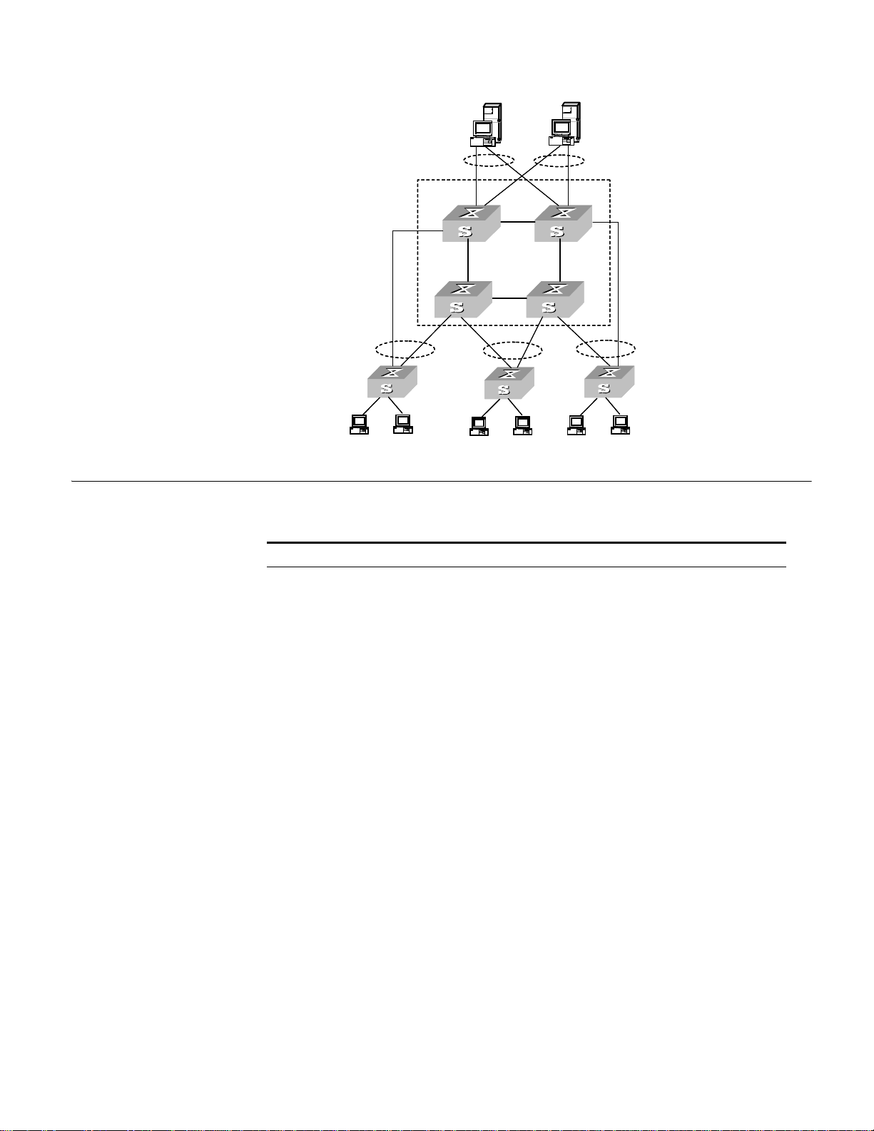
Figure 1 Networking Topology with XRN
Unit 2
Unit 1
Unit3
Unit 4
Fabric
Server
Core
switches
Workgroup
switches
Desktop
PCs
Product Features 27
Product Features Table 4 describes the features:
Tab le 4 Function Features
Features Description
Port 802.1D Learning
Static MAC (unicast/multicast)
Jumbo Frame (9k) (EI models only)
Unidirectional Link Detection (UDLD)
VLAN VLAN compliant with IEEE 802.1Q Standard
Port-based VLAN
Protocol Based VLAN, compliant with IEEE 802.1v Standard (EI
models only)
Voice VLAN
8021.Q in Q Double Tagged VLAN Support (EI models only)
STP protocol Spanning Tree Protocol (STP) / Rapid Spanning Tree Protocol
Flow control IEEE 802.3 flow control (full-duplex)
Traffic Suppression Broadcast/Unicast/Multicast Suppression
(RSTP), compliant with IEEE 802.1D/IEEE802.1w Standard
Multiple Spanning Tree Protocol (MSTP), compliant with IEEE
802.1s Standard
BPDU Guard
Spanning Tree Root Guard
Back-pressure based flow control (half-duplex)
Page 28

28 CHAPTER 1: GETTING STARTED
Tab le 4 Function Features (continued)
Features Description
Multicast Internet Group Management Protocol (IGMP) Snooping
Multicast VLAN Registration (MVR)
Internet Group Management Protocol (IGMP) (EI
Protocol-Independent Multicast-Dense Mode (PIM-DM) (EI
models only)
Protocol-Independent Multicast-Sparse Mode (PIM-SM) (EI
models only)
Mulitcast Source Discovery Protocol (MSDP) (EI models only)
IP routing Static route
RIP V1/v2
OSPF (EI models only)
IP routing policy
Forwarding IP layer 3 broadcast packets
DHCP (Dynamic Host Configuration Protocol) Client
DHCP Server (EI models only)
DHCP Options 60, 82 and 184
DHCP Relay
UDP Relay
Link aggregation Link aggregation
Link Aggregation Control Protocol (LACP), compliant with IEEE
802.3ad Standard
Mirror Mirror based on the traffic classification
Port-based mirror
VLAN-based mirror
Remote mirroring
Security features Multi-level user management and password protect
802.1X Network Login
MAC Based Network Login
Mixed 802.1X and MAC Based Network Login
RADIUS and TACACS+ Authentication, Authorization and
Accounting
PAP, CHAP, EAP-MD5,TLS,TTLS and PEAP Authenticating
Packet filtering
Quality of Service (QoS) Traffic classification
Bandwidth control
Priority
Queues of different priority on the port
Queue scheduling: supports Strict Priority Queuing (SP),
Weighted Round Robin (WRR), WFQ, SP+WFQ, and SP+WRR
QoS profile management manner
models only)
Page 29
Logging in to the Switch 29
Console port
Console cable
Tab le 4 Function Features (continued)
Features Description
Management and
Maintenance
Loading and updates Loading and upgrading of software through the XModem
Command line interface configuration
Configuration through console port
Remote configuration through Telnet or SSH
Configuration through dialing the Modem
SNMP v1/2c/3
System log
Level alarms
Output of debugging information
Ping and Tracert
Remote maintenance with Telnet, Modem and SSHv2
protocol
Loading and upgrading of software through File Transfer
Protocol (FTP) , Trivial File Transfer Protocol (TFTP) and Secure File
Transfer Protocol (SFTP)
Logging in to the Switch
Setting up
Configuration
Environment through
the Console Port
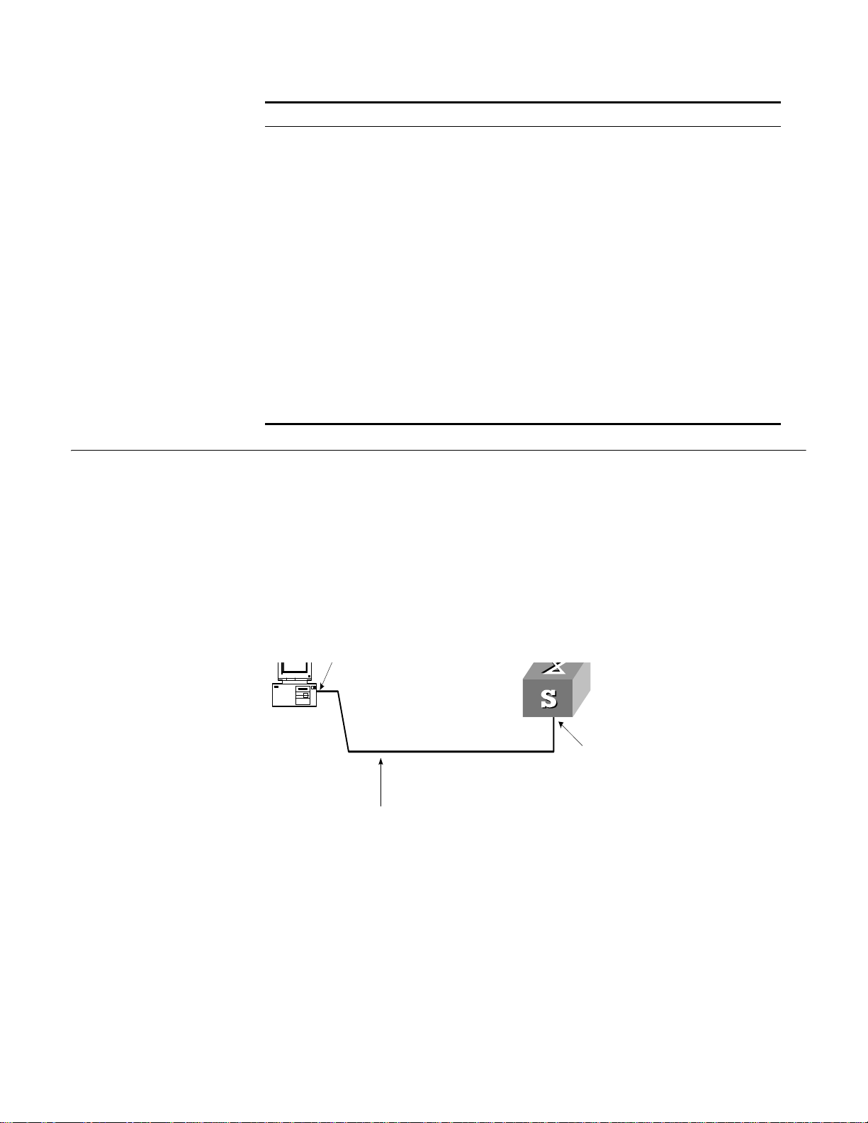
This section describes how to log in to the switch.
Perform the following procedure to set up the configuration environment through
the console port.
1 To set up the local configuration environment, connect the serial port of a PC (or a
terminal) to the console port of the Switch with the console cable (see Figure 2).
Figure 2 Setting up the Local Configuration Environment through the Console Port
2 Run terminal emulator (such as Terminal on Windows 3X or the Hyper Terminal on
Windows 9X) on the PC. Set the terminal communication parameters as follows:
■ Baud rate = 19200
■ Databit = 8
■ Parity check = none
■ Stopbit = 1
■ Flow control = none
■ Terminal type = VT100
Page 30
30 CHAPTER 1: GETTING STARTED
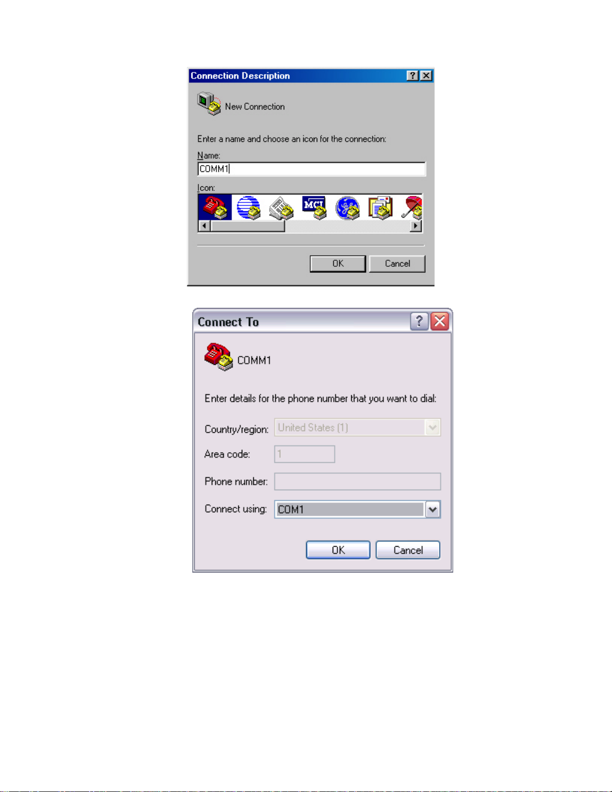
Figure 3 Setting up a New Connection
Figure 4 Configuring the Port for Connection
Page 31

Figure 5 Setting Communication Parameters
Logging in to the Switch 31
Setting up
Configuration
Environment through
Te ln e t
3 The Switch is powered on and it displays self-test information. Press < Enter> to show
the command line prompt such as
4 Enter a command to configure the Switch or view the operation state. Enter a
<SW5500>.
? to
view online help. For details of specific commands, refer to the following sections.
Connecting a PC to the Switch through Telnet
After you have correctly configured the IP address of a VLAN interface for the Switch
through the console port (using the
and added the port (that connects to a terminal) to this VLAN (using the
ip address command in VLAN Interface View),
port
command in VLAN View), you can Telnet this Switch and configure it.
1 Authenticate the Telnet user through the console port before the user logs in by
Te ln e t.
By default, the password is required for authenticating the Telnet user to log in to the
Switch. If a user logs in through the Telnet without password, he will see the prompt
Login password has not been set!
<SW5500>system-view
[SW5500]user-interface vty 0
[SW5500-ui-vty0]set authentication password simple xxxx (xxxx is the
preset login password of the Telnet user)
2 To set up the configuration environment, connect the network port of the PC to a
port on the Switch through the LAN.
Page 32

32 CHAPTER 1: GETTING STARTED
Workstation
Workstation
Server
PC ( for configur ing the switch
via Telnet )
Ethernet port
Ethernet
Workstation
Workstation
Server
PC ( for configur ing the switch
via Telnet )
Ethernet port
Ethernet
3 Run Telnet on the PC and enter the IP address of the VLAN connected to the network
Figure 6 Setting up the Configuration Environment through Telnet
port on the PC.
Figure 7 Running Telnet
4 The terminal displays Login authentication and prompts the user to enter the
logon password. After you enter the correct password, it displays the command line
prompt (such as
try later!
<SW5500>). If the prompt All user interfaces are used, please
appears, too many users are connected to the Switch through Telnet. At
most five Telnet users are allowed to log on to the SW5500 Switch simultaneously.
5 Use the corresponding commands to configure the Switch or to monitor the running
state. Enter
? to view online help. For details of specific commands, refer to the
following chapters.
When configuring the Switch through Telnet, do not modify the IP address of the
Switch unnecessarily, for the modification might end the Telnet connection.
By default, when a Telnet user passes the password authentication to log on to the
Switch, the access level for commands will be Level 0.
Telneting a Switch through another Switch
After a user has logged into a Switch, it is possible to configure another Switch
through the Switch through Telnet. The local Switch serves as Telnet client and the
peer Switch serves as the Telnet server. If the ports connecting these two Switches are
in the same local network, their IP addresses must be configured in the same network
segment. Otherwise, the two Switches must establish a route to communicate with
each other.
to log in to, and configure, another Switch.
As shown in Figure 8, after you Telnet to a Switch, you can run the
telnet command
Page 33

Logging in to the Switch 33
Telnet Client
PC
Telnet Server
Figure 8 Providing Telnet Client Service
1 Authenticate the Telnet user through the console port on the Telnet Server (a Switch)
before login.
By default, the password is required to authenticate Telnet users and to enable them
to log on to the Switch. If a user logs in through Telnet without the password, the
unit displays an error prompt .
<SW5500> system-view
[SW5500] user-interface vty 0
[SW5500-ui-vty0] set authentication password simple xxxx
(where xxxx is the preset login password of Telnet user)
Setting up
Configuration
Environment through a
Dial-up Modem
2 The user logs in to the Telnet Client (Switch). For the login process, refer to
“Connecting a PC to the Switch through Telnet” on page 31.
3 Perform the following on the Telnet Client:
<SW5500> telnet xxxx
(xxxx can be the hostname or IP address of the Telnet Server. If it is the hostname, use
ip host command to specify.)
the
4 Enter the preset login password and you will see the prompt such
prompt
All user interfaces are used, please try later! appears, it indicates
<SW5500>. If the
that too many users are connected to the Switch through Telnet. In this case, connect
later.
5 Use the corresponding commands to configure the Switch or view it running state.
? to view online help. For details of specific commands, refer to the following
Enter
chapters.
Perform the following procedure to set up the configuration environment through a
dial up modem.
1 Authenticate the modem user through the console port of the Switch before the user
logs in to the Switch through a dial-up modem.
By default, the password is required for authenticating the Modem user to log in to
the Switch. If a user logs in through the Modem without the password, the user will
see the prompt
<SW5500>system-view
[SW5500]user-interface aux 0
[SW5500-ui-aux0]set authentication password simple xxxx
login password of the Modem user.)
Login password has not been set!.
(xxxx is the preset
Page 34

34 CHAPTER 1: GETTING STARTED
2 Perform the following configurations on the Modem that is directly connected to the
Switch. (You are not required to configure the Modem connected to the terminal.)
AT&F-------------------Reset Modem factory settings
ATS0=1-----------------Set auto response (ring once)
AT&D-------------------Ignore DTR signal
AT&K0------------------Disable flow control
AT&R1------------------Ignore RTS signal
AT&S0------------------Force DSR to be high-level
ATEQ1&W----------------Bar the modem to send command response or
execution result and save the configurations
After the configuration, enter AT&V to verify the Modem settings.
The Modem configuration commands and outputs may be different according to
different Modems. For details, refer to the User Manual of the Modem.
3Com recommends that the transmission rate on the console port must lower than
that of Modem, otherwise packets may be lost.
3 To set up the remote configuration environment, connect the Modems to a PC (or a
terminal) serial port and the Switch console port respectively (see Figure 9).
Page 35

Logging in to the Switch 35
Modem
Telephone line
Modem
Modem serial port line
Rem o te tel:
1234567
Console port
PSTN
Figure 9 Setting up Remote Configuration Environment
4 Dial for connection to the Switch, using the terminal emulator and Modem on the
remote end. The number you dial is the telephone number of the Modem connected
to the Switch. See Figure 10 and Figure 11.
Figure 10 Setting the Dialed Number
Page 36

36 CHAPTER 1: GETTING STARTED
5 Enter the preset login password on the remote terminal emulator and wait for the
Figure 11 Dialing on the Remote PC
prompt
<SW5500>. Then you can configure and manage the Switch. Enter ? to view
online help. For details of specific commands, refer to the following chapters.
By default, after login, a modem user can access the commands at Level 0.
Page 37

Command Line Interface 37
Command Line Interface
The Switch 5500 family provide a series of configuration commands and command
line interfaces for configuring and managing the Switch. The command line interface
has the following characteristics:
■ Local configuration through the console port.
■ Local or remote configuration through Telnet or SSH.
■ Remote configuration through a dial-up Modem to log in to the Switch.
■ Hierarchy command protection to avoid the unauthorized users accessing the
Switch.
■ Access to online Help by entering ?.
■ Network test commands, such as Tracert and Ping, to troubleshoot the network.
■ Detailed debugging information to help with network troubleshooting.
■ Ability to log in and manage other Switch 5500 units directly, using the Telnet
command.
■ FTP service for users to upload and download files.
■ Ability to view previously executed commands.
■ The command line interpreter that searches for a target not fully matching the
keywords. You can enter the whole keyword or part of it, as long as it is unique
and unambiguous.
Command Line View The Switch 5500 Family provides hierarchy protection for command lines to avoid
unauthorized users accessing it illegally.
Commands are classified into four levels, namely visit level, monitoring level, system
level and management level:
■ Visit level: Commands in this level include network diagnosis tools (such as ping
tracert), commands for the different language environments of the user
and
interface (
language-mode) and the telnet command. The saving of the
configuration file is not allowed at this command level.
■ Monitoring level: Commands in this level include the display command and the
debugging command, and are used for system maintenance, service fault and
diagnosis. The saving of the configuration file is not allowed at this command
level.
■ System level: Commands in this level include service configuration commands,
including routing commands and commands for each network layer, and are used
to provide direct network service to the user.
■ Management level: Commands in this level include those that influence basic
operation of the system and system support module, which plays a support role
for services. Commands in this level include file system commands, FTP
commands, TFTP commands, XModem downloading commands, user
management commands, and level setting commands.
Login users are also classified into four levels that correspond to the four command
levels respectively. After users of different levels log in, they can only use commands
at the levels that are equal to or lower than their own level.
To prevent unauthorized users from illegal intrusion, the user will be identified when
switching from a lower level to a higher level with the
super [ level ] command. User
ID authentication is performed when users at lower level become users at a higher
level. In other words, the user password for the higher level is needed. (Suppose the
Page 38

38 CHAPTER 1: GETTING STARTED
user has entered super password [ level level ] { simple | cipher } password..) For
the sake of confidentiality, on the screen the user cannot see the password that they
entered. Only when correct password is input three times, can the user switch to the
higher level. Otherwise, the original user level will remain unchanged.
Different command views are implemented according to different requirements. They
are related to one another. For example, after logging in to the Switch, you will enter
User View, in which you can only use some basic functions such as displaying the
running state and statistics information. In User View, enter
system-view to enter
System View, in which you can key in different configuration commands and enter
the corresponding views.
The command line provides the following views:
■ User View
■ RIP View
■ System View
■ Ethernet Port View
■ VLAN View
■ VLAN Interface View
■ Local-User View
■ User Interface View
■ FTP Client View
■ RSA Public Key View
■ RSA Key Code View
■ PIM View
Table 5 describes the features of different views and the ways to enter or quit.
Tab le 5 Features of Command Views
Command
view
User View Show the basic
System View Configure system
Ethernet Port
View
VLAN View Configure VLAN
Function Prompt Command to enter Command to exit
<SW5500> This is the view you are in
information about
operation and
statistics
[SW5500] Enter system-view in User
parameters
Configure
[SW5500-Ethernet1/0/1] 100M Ethernet Port View:
Ethernet port
parameters
[SW5500-GigabitEthernet1/0/24]GigabitEthernet Port View:
[SW5500-Vlan1] Enter vlan 1 in System
parameters
■ OSPF View
■ OSPF Area View
■ Route Policy View
■ Basic ACL View
■ Advanced ACL View
■ Layer-2 ACL View
■ User-Defined ACL View
■ QoS Profile View
■ RADIUS Server Group View
■ ISP Domain View
after connecting to the
Switch
View
Enter interface
ethernet 1/0/1 in
System View
Enter interface
gigabitethernet
1/0/24 in System View
View
quit disconnects to
the Switch
quit or return
returns to User View
quit returns to
System View
return returns to
User View
quit returns to
System View
return returns to
User View
Page 39

Tab le 5 Features of Command Views (continued)
Command Line Interface 39
Command
view
VLAN Interface
View
Local-User
View
User Interface
View
FTP Client View Configure FTP
RSA Public Key
View
RSA Key Code
View
PIM View Configure PIM
RIP View Configure RIP
OSPF View Configure OSPF
OSPF Area
View
Route Policy
View
Basic ACL View Define the rule of
Advanced ACL
View
Layer-2 ACL
View
Function Prompt Command to enter Command to exit
Configure IP
interface
parameters for a
VLAN or a VLAN
aggregation
Configure local
user parameters
Configure user
interface
parameters
Client parameters
Configure RSA
public key of SSH
user
Edit RSA public
key of SSH user
parameters
parameters
parameters
Configure OSPF
area parameters
Configure route
policy parameters
basic ACL
Define the rule of
advanced ACL
Define the rule of
layer-2 ACL
[SW5500-Vlan-interface1] Enter interface
vlan-interface 1 in
System View
[SW5500-luser-user1] Enter local-user user1
in System View
[SW5500-ui0] Enter user-interface 0
in System View
[SW5500-ftp] Enter ftp in User View quit returns to
[SW5500-rsa-public-key] Enter rsa
peer-public-key
SW5500003 in System View
[SW5500-rsa-key-code] Enter public-key-code
begin in RSA Public Key
View
[SW5500-PIM] Enter pim in System View quit returns to
[SW5500-rip] Enter rip in System View quit returns to
[SW5500-ospf] Enter ospf in System View quit returns to
[SW5500-ospf-0.0.0.1] Enter area 1 in OSPF View quit returns to OSPF
[SW5500-route-policy] Enter route-policy
policy1 permit node
10 in System View
[SW5500-acl- basic-2000] Enter acl number 2000
in System View
[SW5500-acl-adv-3000] Enter acl number 3000
in System View
[SW5500-acl-ethernetframe-4000] Enter acl number 4000
in System View
quit returns to
System View
return returns to
User View
quit returns to
System View
return returns to
User View
quit returns to
System View
return returns to
User View
System View
peer-public-key
end returns to System
View
public-key-code
end returns to RSA
Public Key View
System View
return returns to
User View
System View
return returns to
User View
System View
return returns to
User View
View
return returns to
User View
quit returns to
System View
return returns to
User View
quit returns to
System View
return returns to
User View
quit returns to
System View
return returns to
User View
quit returns to
System View
return returns to
User View
Page 40

40 CHAPTER 1: GETTING STARTED
Tab le 5 Features of Command Views (continued)
Command
view
User-defined
ACL View
QoS profile
View
RADIUS Server
Group View
ISP Domain
View
Function Prompt Command to enter Command to exit
Define the rule of
user-defined ACL
Define QoS profile [SW5500-qos-profile-h3c] Enter qos-profile h3c
Configure radius
parameters
Configure ISP
domain
parameters
Features and Functions
of Command Line
[SW5500-acl-user-5000] Enter acl number 5000
in System View
in System View
[SW5500-radius-1] Enter radius scheme 1
in System View
[SW5500-isp-3Com.net] Enter domain 3Com.net in
System View
quit returns to
System View
return returns to
User View
quit returns to
System View
return returns to
User View
quit returns to
System View
return returns to
User View
quit returns to
System View
return returns to
User View
Command Line Help
The command line interface provides full and partial online help.
You can get help information through the online help commands, which are
described below:
1 Enter
2 Enter a command with a
? in any view to get all the commands in that view.
? separated by a space. If this position is for parameters, all
the parameters and the corresponding brief descriptions will be listed.
[5500-EI]interface ?
Aux Aux interface
Ethernet Ethernet interface
GigabitEthernet GigabitEthernet interface
Loopback LoopBack interface
NULL NULL interface
Vlan-interface VLAN interface
3 Enter a character string followed by a ?, then all the commands with this character
string as their initials will be listed.
<SW5500>p?
ping
4 Enter a command with a character string and ?, then all the keywords with this
character string as their initials in the command will be listed.
<SW5500>display ver?
version
5 Enter the first letters of a keyword of a command and press <Tab>. If no other
keywords begin with these letters, then this unique keyword will be displayed
automatically.
6 To switch to the Chinese display for the above information, perform the
language-mode command.
Page 41

Command Line Interface 41
Displaying Characteristics of the Command Line
The command line interface provides a pausing function. If the information to be
displayed exceeds one screen, users have three choices, as shown in Table 6.
Tab le 6 Functions of Displaying
Key or Command Function
Press <Ctrl+C> when the display pauses Stop displaying and executing command.
Enter a space when the display pauses Continue to display the next screen of
Press <Enter> when the display pauses Continue to display the next line of
information.
information.
History Command
The command line interface provides a function similar to that of the DosKey.
Commands entered by users are automatically saved by the command line interface
and you can invoke and execute them at any time later. The history command buffer
is defaulted as 10. That is, the command line interface stores 10 history commands
for each user. The operations are shown in Table 7.
Tab le 7 Retrieving History Command
Operation Key Result
Display history command display
history-command
Retrieve the previous history
command
Retrieve the next history
command
Up cursor key <> or <Ctrl+P> Retrieve the previous history
Down cursor key <> or
<Ctrl+N>
Display history command by
user inputting
command, if there is any.
Retrieve the next history
command, if there is any.
Cursor keys can be used to retrieve the history commands in Windows 3.X Terminal
and Telnet. However, in Windows 9X HyperTerminal, the up and down cursor keys
and do not work, because Windows 9X HyperTerminal defines the two keys
differently. In this case, use the combination keys <Ctrl+P> and <Ctrl+N> instead for
the same purpose.
Common Command Line Error Messages
Incorrectly entered commands will cause error messages to be reported to users. The
common error messages are listed in Table 8.
Tab le 8 Common Command Line Error Messages
Error messages Causes
Unrecognized command ■ Cannot find the command
■ Cannot find the keyword
■ Wrong parameter type
■ The value of the parameter exceeds the range
Incomplete command The command is incomplete.
Too many parameters Too many parameters have been entered.
Ambiguous command The parameters entered are not specific.
Page 42

42 CHAPTER 1: GETTING STARTED
Editing Characteristics of Command Line
The command line interface provides basic command editing and supports the editing
of multiple lines. A command cannot be longer than 256 characters. See Table 9.
Tab le 9 Editing Functions
Key Function
Common keys Insert from the cursor position and the cursor moves to
the right, if the edition buffer still has free space.
Backspace Delete the character preceding the cursor and the cursor
moves backward.
Leftwards cursor key <> or <Ctrl+B> Move the cursor a character backward
Rightwards cursor key <> or <Ctrl+F> Move the cursor a character forward
Up cursor key <> or <Ctrl+P>
Down cursor key <> or <Ctrl+N>
<Tab> Press <Tab> after typing an incomplete keyword and the
Retrieve the history command.
system will display partial help: If the keyword matching
the one entered is unique, the system will replace it with
the complete keyword and display it in a new line; if
there is no matched keyword or the matched keyword is
not unique, the system will do no modification but
display the originally typed word in a new line.
User Interface Configuration
User interface configuration is another way provided by the Switch to configure and
manage the port data.
Switch 5500 family Switches support the following configuration methods:
■ Local configuration through the console port
■ Local and remote configuration through Telnet or SSH through an Ethernet port
■ Remote configuration through a dial-up modem through the console port.
According to the above-mentioned configuration methods, there are two types of
user interfaces:
■ AUX user interface
AUX user interface is used to log in to the Switch through the console port. A
fabric can have up to eight AUX user interfaces.
■ VTY user interface
VTY user interface is used to Telnet to the Switch. A Switch can have up to five
VTY user interfaces.
For SW5500 family Switches, AUX port, and console port are the same port. There is
only the one type of AUX user interface.
The user interface is numbered by absolute number or relative number.
To number the user interface by absolute number:
■ The AUX user interface is the first interface—user interface 0. The number ranges
from 0 to 7.
■ The VTY is numbered after the AUX user interface. The absolute number of the
first VTY is the AUX user interface number plus 1. The number ranges from 8 to
12.
Page 43

User Interface Configuration 43
To number the user interface by relative number, represented by interface + number
assigned to each type of user interface:
■ AUX user interface = AUX 0.
■ The first VTY interface = VTY 0, the second one = VTY 1, and so on.
User Interface Configuration
Tasks for configuring the user interface are described in the following sections:
■ Entering User Interface View
■ Configuring the User Interface-Supported Protocol
■ Configuring the Attributes of AUX (Console) Port
■ Configuring the Terminal Attributes
■ Managing Users
■ Configuring Redirection
Entering User Interface View
Use the
user-interface command to enter a User Interface View. You can enter a
single User Interface View or multi User Interface View to configure one or more user
interfaces respectively.
Perform the following configuration in System View.
Table 10 Entering User Interface View
Operation Command
Enter a single User Interface View or multi User
Interface Views
user-interface [ type ]
first-number [ last-number ]
Configuring the User Interface-Supported Protocol
The following command is used for setting the supported protocol by the current user
interface. You can log in to the Switch only through the supported protocol. The
configuration becomes effective when you log in again.
Perform the following configurations in User Interface (VTY user interface only) View.
Table 11 Configuring the User Interface-supported Protocol
Operation Command
Configure the user interface-supported
protocol
protocol inbound { all | ssh |
telnet }
By default, the user interface supports Telnet and SSH protocols.
If the Telnet protocol is specified, to ensure a successful login through Telnet, you
must configure the password by default.
If SSH protocol is specified, to ensure a successful login, you must configure the local
or remote authentication of username and password using the
authentication-mode scheme command. The protocol inbound ssh
configuration fails if you configure authentication-mode password and
authentication-mode none. When you configure SSH protocol successfully for the
user interface, then you cannot configure
authentication-mode none any more.
authentication-mode password and
Page 44

44 CHAPTER 1: GETTING STARTED
Configuring the Attributes of AUX (Console) Port
Use the
speed, flow control, parity, stop bit, and data bit commands to
configure these attributes of the AUX (console) port.
Perform the following configurations in User Interface (AUX user interface only) View.
Configuring the Transmission Speed on the AUX (Console) Port
Table 12 Configuring the Transmission Speed on the AUX (Console) Port
Operation Command
Configure the transmission speed on the AUX
(console) port
Restore the default transmission speed on the AUX
(console) port
speed speed_value
undo speed
By default, the transmission speed on
the AUX (console) port is 9600bps.
Configuring the Flow Control on the AUX (Console) Port
Table 13 Configuring the Flow Control on the AUX (Console) Port
Operation Command
Configure the flow control on the AUX (console) port flow-control { hardware | none
| software }
Restore the default flow control mode on the AUX
(console) port
undo flow-control
By default, the flow control on the AUX (console) port is none, that is, no flow control
will be performed.
Configuring Parity on the AUX (Console) Port
Table 14 Configuring Parity on the AUX (Console) Port
Operation Command
Configure parity mode on the AUX (console)
port
Restore the default parity mode undo parity
parity { even | mark | none | odd |
space }
By default, the parity on the AUX (console) port is none, that is, no parity bit.
Configuring the Stop Bit of AUX (Console) Port
Table 15 Configuring the Stop Bit of AUX (Console) Port
Operation Command
Configure the stop bit of the AUX (console) port stopbits { 1 | 1.5 | 2 }
Restore the default stop bit of the AUX (console) port undo stopbits
By default, the
Configuring the Data Bit of the
Table 16 Configuring the Data Bit of the AUX (Console) Port
Operation Command
Configure the data bit of the AUX (console) port databits { 7 | 8}
Restore the default data bit of the AUX (console) port undo databits
By default, the
AUX (console) port supports 1 stop bit.
AUX (Console) port
AUX (console) port supports 8 data bits.
Page 45

User Interface Configuration 45
Configuring the Terminal Attributes
The following commands can be used for configuring the terminal attributes,
including enabling/disabling terminal service, disconnection upon timeout, lockable
user interface, configuring terminal screen length, and history command buffer size.
Perform the following configuration in User Interface View. Perform the
lock
command in User View.
Enabling/Disabling Terminal Service After terminal service is disabled on a user
interface, you cannot log in to the Switch through the user interface. However, the
user logged in through the user interface before disabling the terminal service can
continue his operation. After such user logs out, he cannot log in again. In this case, a
user can log in to the Switch through the user interface only when the terminal
service is enabled again.
Table 17 Enabling/Disabling Terminal Service
Operation Command
Enable terminal service shell
Disable terminal service undo shell
By default, terminal service is enabled on all the user interfaces.
Note the following points:
■ For security, the undo shell command can only be used on the user interfaces
other than AUX user interface.
■ You cannot use this command on the user interface through which you log in.
■ You will be asked to confirm before using undo shell on any legal user interface.
Configuring Idle-timeout
Table 18 Configuring Idle-timeout
Operation Command
Configure idle-timeout idle-timeout minutes [ seconds ]
Restore the default idle-timeout undo idle-timeout
By default, idle-timeout is enabled and set to 10 minutes on all the user interfaces.
That is, the user interface will be disconnected automatically after 10 minutes without
any operation.
idle-timeout 0 Disables idle-timeout.
Locking the User Interface This configuration locks the current user interface and
prompts the user to enter the password. This makes it impossible for others to
operate in the interface after the user leaves.
Table 19 Locking the User Interface
Operation Command
Lock user interface lock
Page 46

46 CHAPTER 1: GETTING STARTED
Setting the Screen Length If a command displays more than one screen of
information, you can use the following command to set how many lines to be
displayed in a screen, so that the information can be separated in different screens
and you can view it more conveniently.
Table 20 Setting the Screen Length
Operation Command
Set the screen length screen-length screen_length
Restore the default screen length undo screen-length
By default, the terminal screen length is 24 lines.
screen-length 0 Disables screen display separation function.
Setting the History Command Buffer Size
Table 21 Setting the History Command Buffer Size
Operation Command
Set the history command buffer size history-command max-size value
Restore the default history command buffer size undo history-command max-size
By default, the size of the history command buffer is 10, that is, 10 history commands
can be saved.
Managing Users
The management of users includes the setting of user login authentication method,
level of command which a user can use after logging in, level of command which a
user can use after logging in from a specific user interface, and command level.
Configuring the Authentication Method The following command is used for
configuring the user login authentication method to deny the access of an
unauthorized user.
Perform the following configuration in User Interface View.
Table 22 Configuring the Authentication Method
Operation Command
Configure the authentication method authentication-mode { password | scheme }
Configure no authentication authentication-mode none
By default, terminal authentication is not required for users logged in through the
console port, whereas the password is required for authenticating the Modem and
Telnet users when they log in.
1 Perform local password authentication to the user interface
authentication-mode password command, you can perform local password
Using
authentication. That is, you need use the command below to configure a login
password to login successfully.
Page 47

User Interface Configuration 47
Perform the following configuration in User Interface View.
Table 23 Configuring the local authentication password
Operation Command
Configure the local
authentication password
Remove the local
authentication password
set authentication password { cipher | simple
}password
undo set authentication password
Configure for password authentication when a user logs in through a VTY 0 user
interface and set the password to 3Com.
[SW5500]user-interface vty 0
[SW5500-ui-vty0]authentication-mode password
[SW5500-ui-vty0]set authentication password simple 3Com
2 Perform local or remote authentication of the username and the password to the user
interface
Using the
authentication-mode scheme command, you can perform local or remote
authentication of username and password. The type of the authentication depends
on your configuration.
In the following example, local username and password authentication are
configured.
Perform username and password authentication when a user logs in through VTY 0
user interface and set the username and password to zbr and 3Com respectively.
[SW5500-ui-vty0]authentication-mode scheme
[SW5500-ui-vty0]quit
[SW5500]local-user zbr
[SW5500-luser-zbr]password simple 3Com
[SW5500-luser-zbr]service-type telnet
3 No authentication
[SW5500-ui-vty0]authentication-mode none
By default, the password is required for authenticating Modem and Telnet users when
they log in. If the password has not been set, when a user logs in, he will see the
prompt
Login password has not been set!
If the authentication-mode none command is used, the Modem and Telnet users
will not be required to enter a password.
Setting the command level used after a user has logged on The following
command is used for setting the command level used after a user logs in.
Perform the following configuration in Local-User View.
Table 24 Setting the Command Level used after a User Logs In
Operation Command
Set command level used
after a user logs in
Restore the default
command level used after
a user logs in
service-type { ftp [ ftp-directory directory |
lan-access | { ssh | telnet | terminal }* [
level level ] }
undo service-type { ftp [ ftp-directory ]
lan-access | { ssh | telnet | terminal }* }
Page 48

48 CHAPTER 1: GETTING STARTED
By default, the specified logged-in user can access the commands at Level 1.
Setting the Command Level used after a User Logs In from a User Interface
You can use the following command to set the command level after a user logs in
from a specific user interface, so that a user is able to execute the commands at such
command level.
Perform the following configuration in User Interface View.
Table 25 Setting the Command Level used after a User Logs In from a User Interface
Operation Command
Set command level used after a user logs in from a
user interface
Restore the default command level used after a user
logs in from a user interface
user privilege level level
undo user privilege level
By default, a user can access the commands at Level 3 after logging in through the
AUX user interface, and the commands at Level 0 after logging in through the VTY
user interface.
When a user logs in to the Switch, the available command level depends on two
points. One is the command level that the user is allowed to access, the other is the
set command level of this user interface. If the two levels are different, the former will
be taken. For example, the command level of VTY 0 user interface is 1, however, you
have the right to access commands of level 3; if you log in from VTY 0 user interface,
you can access commands of level 3 and lower.
Setting the command priority The following command is used for setting the
priority of a specified command in a certain view. The command levels include visit,
monitoring, system, and management, which are identified with 0 through 3
respectively. An administrator assigns authorities as per user requirements.
Perform the following configuration in System View.
Table 26 Setting the Command Priority
Operation Command
Set the command priority
in a specified view.
Restore the default
command level in a
specified view.
command-privilege level level view view command
command-privilege view view command
Do not change the command level unnecessarily for it may cause inconvenience with
maintenance and operation.
Configuring Redirection
send command The following command can be used for sending messages
between user interfaces.
Perform the following configuration in User View.
Table 27 Configuring to Send Messages Between Different User Interfaces
Operation Command
Configuring to send messages between
different user interfaces.
send { all | number | type number }
Page 49

User Interface Configuration 49
auto-execute command The following command is used to automatically run a
command after you log in. After a command is configured to be run automatically, it
will be automatically executed when you log in again.
This command is usually used to automatically execute the
telnet command on the
terminal, which will connect the user to a designated device automatically.
Perform the following configuration in User Interface View.
Table 28 Configuring to Automatically Run the Command
Operation Command
Configure to automatically run the command auto-execute command text
Configure not to automatically run the
command
undo auto-execute command
Note the following points:
■ After executing this command, the user interface can no longer be used to carry
out the routine configurations for the local system. Use this command with
caution.
■ Make sure that you will be able to log in the system in another way and cancel the
configuration, before you use the
auto-execute command command and save the
configuration.
Telnet 10.110.100.1 after the user logs in through VTY0 automatically.
[SW5500-ui-vty0]auto-execute command telnet 10.110.100.1
Displaying and
Debugging User
Interface
When a user logs on through VTY 0, the system will run telnet 10.110.100.1
automatically.
After the above configuration, use the display command in any view to display the
running of the user interface configuration, and to verify the effect of the
configuration.
Use the
Table 29 Displaying and Debugging User Interface
Operation Command
Clear a specified user interface free user-interface [ type ] number
Display the user application information
of the user interface
Display the physical attributes and some
configurations of the user interface
free command in User View to clear a specified user interface.
display users [ all ]
display user-interface [ type number |
number ] [ summary ]
Page 50

50 CHAPTER 1: GETTING STARTED
Page 51

ADDRESS MANAGEMENT
2
Introduction to Address Management
Configuring Address Management
Configuring a
Port-Based Address
Management IP Address
Pool
CONFIGURATION
You can easily configure the switch on which the Address Manage (AM) feature is
enabled to allow a user with the specified MAC address to gain network access
through the specified IP address in a small network, such as a campus network. This
facilitates the implementation of user management and accounting.
Address management configuration tasks include:
■ Configuring a port-based address management IP address pool
■ Binding the MAC address and IP address of a legal user to the specified port
By setting an address management IP address pool on a port, you can allow a user
with the specified IP addresses to access the network. The Ethernet switch allows the
packets in the IP address pool whose IP addresses are the source IP addresses to pass
the port for layer 3 forwarding. The switch does not forward any packet from any IP
address not configured in the IP address pool.
Table 30 Configure a port-based address management IP address pool
Operation Command Description
Enter system view system-view -
Enable address management am enable Required
The IP address pool configured on
each port to control layer 3
forwarding takes effect only after
address management is enabled.
Enter Ethernet port view interface interface-type
interface-number
Configure an address
management IP address pool
on a port
am ip-pool { address-list } Required
-
By default, the address
management IP address pool on
each port is null; that is, the switch
permits all packets to pass.
Binding the MAC
Address and IP Address
of a Legal User to the
Specified Port
When you are configuring an address management IP address pool on a port, if the IP
addresses in this IP address pool are those configured in the static ARP on another
port, the system will prompt you to delete the corresponding static ARP to ensure
that the binding takes effect.
You cannot configure static ARP for the IP address restricted by AM; otherwise, AM
fails.
This configuration binds the specified MAC addresses and IP addresses, only allowing
the packets from legal MAC addresses and legal IP addresses to be forwarded by the
switch. None of the following combinations enables network access through the
switch:
■ Illegal MAC address + illegal IP address
■ Legal MAC address + illegal IP address
■ Illegal MAC address + legal IP address
Page 52

52 CHAPTER 2: ADDRESS MANAGEMENT CONFIGURATION
Ext ernal network
Hub
Ext ernal network
Hub
Perform the following operations to bind the MAC address and IP address of a legal
user to the specified port; no other configuration is required.
Table 31 Bind the MAC address and IP address of a legal user to the specified port
Operation Command Description
Enter system view system-view -
Bind the MAC address and IP address
of a legal user to the specified port
Enter Ethernet port view interface interface-type
Bind the MAC address and IP address
of a legal user to the specified port
am user-bind mac-addr
mac-address ip-addr ip-address [
interface interface-type
interface-number ]
interface-number
am user-bind mac-addr
mac-address ip-addr ip-address
Optional
-
Optional
Address Management Configuration Example
Port-Based Address
Management IP Address
Pool Configuration
Example
This section contains configuration examples.
Network requirements
The GigabitEthernet1/0/1 port of the switch is connected to multiple PCs.
Network diagram
Figure 12 Network diagram for address management
Configuration procedure
To enable address management, enter the following:
<S5500> system-view
[S5500] am enable
Page 53

Address Management Configuration Example 53
Ext ernal network
Hub
Ext ernal network
Hub
To configure an address management IP address pool on GigabitEthernet 1/0/1,
allowing 20 IP addresses starting from 202.10.20.1 to 202.10.20.20 to access the
network, enter the following:
[S5500] interface GigabitEthernet 1/0/1
[S5500-GigabitEthernet 1/0/1] am ip-pool 202.10.20.1 20
Configuration Example
of Binding the MAC
Address and IP Address
of a Legal User
Network requirements
The GigabitEthernet1/0/1 port of the switch is connected to multiple PCs.
Network diagram
Figure 13 Network diagram for address management
Configuration procedure
To configure to bind MAC addresses and IP addresses to GigabitEthernet 1/0/1, only
allowing a PC whose MAC address is 00e0-fc00-3900 to access the network by using
the IP address 202.10.20.30, enter the following:
<S5500> system-view
[S5500] interface GigabitEthernet 1/0/1
[S5500-GigabitEthernet 1/0/1] am user-bind mac-addr 00e0-fc00-3900
ip-address 202.10.20.30
Page 54

54 CHAPTER 2: ADDRESS MANAGEMENT CONFIGURATION
Page 55

3
PORT OPERATION
This chapter covers the following topics:
■ Ethernet Port Configuration Introduction
■ Link Aggregation Configuration
■ Global Broadcast Suppression Feature
■ Configuring VCT
■ Global Broadcast Suppression Feature
■ Displaying Port Configuration Information in Brief
■ Displaying Information About a Specified Optical Port
Ethernet Port Configuration Introduction
Ethernet Port
Configuration
The following features are found in the Ethernet ports of the Switch 5500
■ 10/100BASE-T Ethernet ports support MDI/MDI-X auto-sensing. They can operate
in half-duplex, full-duplex and auto-negotiation modes. They can negotiate with
other network devices to determine the operating mode and speed. Thus the
appropriate operating mode and speed is automatically configured and the system
configuration and management is greatly streamlined.
■ Gigabit SFP ports operate in 1000Mbps full duplex mode. The duplex mode can be
set to full (full-duplex) and auto (auto-negotiation) and its speed can be set to
1000 (1000Mbps) and auto (auto-negotiation).
Ethernet port configuration is described in the following sections:
■ Entering Ethernet Port View
■ Enabling/Disabling an Ethernet Port
■ Setting the Description Character String for the Ethernet Port
■ Setting the Duplex Attribute of the Ethernet Port
■ Setting Speed on the Ethernet Port
■ Setting the Cable Type for the Ethernet Port
■ Enabling/Disabling Flow Control for the Ethernet Port
■ Permitting/Forbidding Jumbo Frames to Pass through an Ethernet Port
■ Setting the Ethernet Port Suppression Ratio
■ Setting the Link Type for an Ethernet Port
■ Adding an Ethernet Port to Specified VLANs
■ Setting the Default VLAN ID for the Ethernet Port
■ Setting Loopback Detection for an Ethernet Port
■ Configuring VCT
■ VCT Configuration Example
■ Copying Port Configuration to Other Ports
Page 56

56 CHAPTER 3: PORT OPERATION
Entering Ethernet Port View
Before configuring an Ethernet port, enter Ethernet Port View.
Perform the following configuration in System View.
Table 32 Entering Ethernet Port View
Operation Command
Enter Ethernet Port View interface { interface_type
interface_num | interface_name }
Enabling/Disabling an Ethernet Port
Use the following command to disable or enable the port. After configuring the
related parameters and protocol of the port, you can use the following command to
enable the port. If you do not want a port to forward data, use the command to
disable it.
Perform the following configuration in Ethernet Port View.
Table 33 Enabling/Disabling an Ethernet Port
Operation Command
Disable an Ethernet port shutdown
Enable an Ethernet port undo shutdown
By default, the port is enabled.
Setting the Description Character String for the Ethernet Port
To distinguish the Ethernet ports, use the following command to assign a description
to each port.
Perform the following configuration in Ethernet Port View.
Table 34 Setting the Description Character String for the Ethernet Port
Operation Command
Set description character string for Ethernet port. description text
Delete the description character string of Ethernet. undo description
By default, the port description is a null character string.
Setting the Duplex Attribute of the Ethernet Port
To configure a port to send and receive data packets at the same time, set it to
full-duplex. To configure a port to either send or receive data packets, set it to
half-duplex. If the port has been set to auto-negotiation mode, the local and peer
ports will automatically negotiate the duplex mode.
Perform the following configuration in Ethernet Port View.
Table 35 Setting the Duplex Attribute for the Ethernet Port
Operation Command
Set duplex attribute for Ethernet port. duplex { auto | full | half }
Restore the default duplex attribute of Ethernet port. undo duplex
Note that 10/100BASE-T Ethernet ports support full duplex, half duplex and
auto-negotiation, which can be set as required. Gigabit Ethernet ports support full
Page 57

Ethernet Port Configuration Introduction 57
duplex and can be configured to operate in full (full duplex) or auto
(auto-negotiation) mode.
The port defaults to auto (auto-negotiation) mode.
Setting Speed on the Ethernet Port
Use the following command to set the speed of the Ethernet port. If the speed is set
to auto-negotiation mode, the local and peer ports will automatically negotiate the
port speed.
Perform the following configuration in Ethernet Port View.
Table 36 Setting Speed on the Ethernet Port
Operation Command
Set the Ethernet port speed speed { 10 | 100 | 1000 | auto }
Restore the default speed for the Ethernet port undo speed
Note that 10/100BASE-T Ethernet ports support 10Mbps, 100Mbps and
auto-negotiation, which can be set as required. Gigabit Ethernet ports support
1000Mbps and can be configured to operate at 1000 (1000Mbps) or auto
(auto-negotiation) speed.
By default, the speed of the port set to auto mode.
Setting the Cable Type for the Ethernet Port
Ethernet ports support straight-through and cross-over network cables. Use the
following command to configure the cable type.
Perform the following configuration in Ethernet Port View.
Table 37 Setting the Type of the Cable Connected to an Ethernet Port
Operation Command
Set the type of the cable connected to an Ethernet
port.
Restore the default type of the cable connected to an
Ethernet port.
mdi { across | auto | normal }
undo mdi
By default, the cable type is auto (auto-recognized). That is, the system can
automatically recognize the type of cable connecting to the port.
Enabling/Disabling Flow Control for the Ethernet Port
After flow control is enabled in both the local and the peer Switch, if congestion
occurs in the local Switch, the Switch will inform its peer to pause packet sending. In
this way, packet loss is reduced. The flow control function of the Ethernet port can be
enabled or disabled using the following command.
Perform the following configuration in Ethernet Port View.
Table 38 Enabling/Disabling Flow Control for an Ethernet Port
Operation Command
Enable Ethernet port flow control flow-control
Disable Ethernet port flow control undo flow-control
By default, Ethernet port flow control is disabled.
Page 58

58 CHAPTER 3: PORT OPERATION
Permitting/Forbidding Jumbo Frames to Pass through an Ethernet Port
An Ethernet port may encounter jumbo frames exceeding the standard frame length,
when switching large throughput data like transmitting files. This command can
forbid or permit jumbo frames to pass through an Ethernet port.
Perform the following configuration in Ethernet Port View.
Table 39 Permitting/Forbidding Jumbo Frame to Pass through the Ethernet Port
Operation Command
Permit jumbo frame to pass through the Ethernet port jumboframe enable
Forbid jumbo frame to pass through the Ethernet port undo jumboframe enable
By default, jumbo frames with lengths between 1518 bytes and 9216 bytes inclusive
are permitted to pass through an Ethernet port.
Setting the Ethernet Port Suppression Ratio
Use the following commands to restrict broadcast/multicast/unicast traffic. Once
traffic exceeds the value set by the user, the system will maintain an appropriate
packet ratio by discarding the overflow traffic, so as to suppress storm, avoid
congestion and ensure the normal service.
Perform the following configuration in Ethernet Port View.
Table 40 Setting the Ethernet Port Suppression Ratio
Operation Command
Set Ethernet port broadcast
suppression ratio
Restore the default Ethernet port
broadcast suppression ratio
Set Ethernet port multicast
suppression ratio
Restore the default Ethernet port
multicast suppression ratio
Set Ethernet port unicast suppression
ratio
Restore the default Ethernet port
unicast suppression ratio
broadcast-suppression { ratio | pps
bandwidth }
undo broadcast-suppression
multicast-suppression { ratio | pps
bandwidth }
undo multicast-suppression
unicast-suppression { ratio | pps
bandwidth }
undo unicast-suppression
By default, all traffic is allowed to pass through, that is, no suppression is performed.
Setting the Link Type for an Ethernet Port
An Ethernet port can operate in four different link types: access, hybrid, trunk and stack.
An access port carries one VLAN only, used for connecting to the user's computer. A trunk
port can belong to more than one VLAN and receive/send the packets on multiple VLANs,
used for connection between the Switches. A hybrid port can also carry more than one
VLAN and receive/send the packets on multiple VLANs, used for connecting to both
Switches and the user's computers. The difference between a hybrid port and a trunk port
is that a hybrid port allows the packets from multiple VLANs to be sent without tags, but
a trunk port only allows the packets from the default VLAN to be sent without tags.
Page 59

Ethernet Port Configuration Introduction 59
Perform the following configuration in Ethernet Port View.
Table 41 Setting the Link Type for the Ethernet Port
Operation Command
Configure the port as an access port port link-type access
Configure the port as a hybrid port port link-type hybrid
Configure the port as a trunk port port link-type trunk
Configure the port as a stack port port link-type xrn-fabric
Restore the default link type, that is, access port undo port link-type
By default, the port is access port.
Note that:
■ You can configure four types of ports concurrently on the same Switch, but you
cannot switch port type between trunk port, hybrid port and stack port. You must
return it first into access port and the set it as the other type. For example, you
cannot configure a trunk port directly as a hybrid port, but first set it as an access
port and then as a hybrid port.
■ For the Switch 5500-SI 28-Port, Switch 5500-EI 28-Port, and Switch 5500-EI PWR
28-Port, GigabitEthernet1/0/27 and GigabitEthernet1/0/28 ports can be
configured as a stack port; For the Switch 5500-SI 52-port, Switch 5500-EI
52-Port, Switch 5500-EI PWR 52-Port, GigabitEthernet1/0/51 and
GigabitEthernet1/0/52 ports can be configured as a stack port.
Adding an Ethernet Port to Specified VLANs
Use the following commands to add an Ethernet port to a specified VLAN. An access
port can only be added to one VLAN, while hybrid and trunk ports can be added to
multiple VLANs.
Perform the following configuration in Ethernet Port View.
Table 42 Adding the Ethernet Port to Specified VLANs
Operation Command
Add the current access port to a specified
VLAN
Add the current hybrid port to specified
VLANs
Add the current trunk port to specified VLANs port trunk permit vlan {
Remove the current access port from to a
specified VLAN.
Remove the current hybrid port from to
specified VLANs.
Remove the current trunk port from specified
VLANs.
port access vlan vlan_id
port hybrid vlan vlan_id_list {
tagged | untagged }
vlan_id_list | all }
undo port access vlan
undo port hybrid vlan vlan_id_list
undo port trunk permit vlan {
vlan_id_list | all }
Note that the access port shall be added to an existing VLAN other than VLAN 1. The
VLAN to which a hybrid port is added must have already exist. The one to which a
trunk port is added cannot be VLAN 1.
After adding an Ethernet port to specified VLANs, the local port can forward packets
of these VLANs. Hybrid and trunk ports can be added to multiple VLANs, thereby
implementing the VLAN intercommunication between peers. For a hybrid port, you
Page 60

60 CHAPTER 3: PORT OPERATION
can configure to tag some VLAN packets, based on which the packets can be
processed differently.
Setting the Default VLAN ID for the Ethernet Port
Because the access port can only be included in one VLAN, its default VLAN is the one
to which it belongs. Because a hybrid port and a trunk port can be included in several
VLANs, you must configure the default VLAN ID. If the default VLAN ID has been
configured, the packets without VLAN Tag will be forwarded to the port that belongs
to the default VLAN. When sending the packets with VLAN Tag, if the VLAN ID of the
packet is identical to the default VLAN ID of the port, the system will remove VLAN
Tag before sending this packet.
Perform the following configuration in Ethernet Port View.
Table 43 Setting the Default VLAN ID for an Ethernet Port
Operation Command
Set the default VLAN ID for a hybrid port. port hybrid pvid vlan
vlan_id
Set the default VLAN ID for a trunk port port trunk pvid vlan vlan_id
Restore the default VLAN ID of a hybrid port to the
default value
Restore the default VLAN ID of a trunk port to the
default value
undo port hybrid pvid
undo port trunk pvid
By default, the VLAN of a hybrid port and a trunk port is VLAN 1 and that of the
access port is the VLAN to which it belongs.
Note that to guarantee the proper packet transmission, the default VLAN ID of the
local hybrid port or trunk port should be identical with that of the hybrid port or trunk
port on the peer Switch.
Configuring Loopback Detection for Ethernet Ports
The goal of loopback detection is to check whether the ports of switch have
loopback.
After users enable loopback detection for Ethernet ports, the switch will monitor
whether the ports have loopback on a regular basis; if the switch detects loopback for
a particular port, it will put that port under control.
■ For Access port: If system detects loopback for a port, it will shut down that port,
send a Trap message to the terminal, and delete the corresponding MAC address
forwarding entry.
■ For Trunk ports and Hybrid ports: If system detects loopback for a port, it will send
a Trap message to the terminal. If the loopback detection and control function for
that port is enabled at the same time, the system will then shut down the given
port, send a Trap message to the terminal, and delete the corresponding MAC
address forwarding entry.
Table 44 Configure loopback detection for Ethernet port
Operation Command Description
Enter system view system-view -
Enable the global port
loopback detection
Set the time interval for
loopback detection function
loopback-detection
enable
loopback-detection
interval-time time
Optional.By default, the global port
loopback detection function is disabled.
Optional.
Set to 30 seconds by default.
Page 61

Ethernet Port Configuration Introduction 61
Table 44 Configure loopback detection for Ethernet port (continued)
Operation Command Description
Enter the Ethernet port view interface
Enable the loopback detection
function for a specified port
Enable the loopback detection
and control function for Trunk
ports and Hybrid ports
Configure the system to
detect loopback in all the
VLANs with Trunk ports and
Hybrid ports
Display the loopback detection
information
interface-type
interface-number
loopback-detection
enable
loopback-detection
control enable
loopback-detection
per-vlan enable
display
loopback-detection
-
Optional.By default, the loopback
detection function is disabled.
Optional.By default, the loopback
detection and control function is disabled.
Optional.
By default, system only detects loopback
for the default VLANs with Trunk ports
and Hybrid ports.
Optional.
This command can be used under any
view
Loopback detection function for a port is enabled only when the loopback-detection
enable command is enabled under both system view and port view.
When the undo loopback-detection enable command is used under system view, the
loopback detection function will be disabled for all ports.
Setting Loopback Detection for an Ethernet Port
Use the following command to enable port loopback detection and set the detection
interval for the external loopback condition of each port. If there is a loopback port
found, the Switch will put it under control.
Other correlative configurations function only when port loopback detection is
enabled in System View.
Perform the following configuration in the view listed in Table 45.
Table 45 Setting Loopback Detection for the Ethernet Port
Operation Command
Enable loopback detection on the port (System
View/Ethernet Port View)
Disable loopback detection on the port (System
View/Ethernet Port View)
Enable the loopback controlled function of the
trunk and hybrid ports (Ethernet Port View)
Disable the loopback controlled function of the
trunk and hybrid ports (Ethernet Port View)
Set the external loopback detection interval of
the port (System View)
Restore the default external loopback detection
interval of the port (System View)
Configure that the system performs loopback
detection to all VLANs on Trunk and Hybrid
ports (Ethernet Port View)
Configure that the system only performs
loopback detection to the default VLANs on the
port (Ethernet Port View)
loopback-detection enable
undo loopback-detection enable
loopback-detection control
enable
undo loopback-detection control
enable
loopback-detection
interval-time time
undo loopback-detection
interval-time
loopback-detection per-vlan
enable
undo loopback-detection
per-vlan enable
Page 62

62 CHAPTER 3: PORT OPERATION
By default, port loopback detection and the loopback detection control function on
trunk and hybrid ports are disabled. The detection interval is 30 seconds, and the
system detects the default VLAN on the trunk and hybrid ports.
Configuring VCT
You can start the virtual cable test (VCT) to make the system test the cable connected
to the current electrical Ethernet port, and the system will return the test results in five
seconds. The test items include: whether short or open circuit exists in the Rx/Tx
direction of the cable, and what is the length of the cable in normal status or the
length from the port to the fault point of the cable.
Table 46 Configure VCT
Operation Command Description
Enter system view system-view -
Enter Ethernet port view interface
interface-type
interface-number
Start VCT to make the system test
the cable connected to the current
electrical Ethernet port
virtual-cable-test Required
-
By default, this test is not started.
VCT Configuration Example
EthernetPort Security
Features
Network requirements
Start VCT to make the system test the cable connected to the following port.
Configuration procedure
1 Enter the system view.
<S5500> system-view
2 Enter the Ethernet1/0/1 port view.
[S5500] interface Ethernet 1/0/1
3 Start VCT.
[S5500-Ethernet1/0/1] virtual-cable-test
Cable status: abnormal(open), 7 metres
Pair Impedance mismatch: yes
Pair skew: 4294967294 ns
Pair swap: swap
Pair polarity: normal
Insertion loss: 7 db
Return loss: 7 db
Near-end crosstalk: 7 db
Port security is a security mechanism to control network access. It is an expansion of
the current 802.1x and MAC address authentication. This scheme controls the
incoming/outgoing packets on port by checking the MAC addresses contained in
data frames, and provides multiple security and authentication modes; this greatly
improves the security and manageability of the system.
The port security scheme provides the following features:
1 NTK: Need to Know feature. By way of checking the destination MAC addresses of
the data frames to be sent from a port, this feature ensures that only successfully
Page 63

Ethernet Port Configuration Introduction 63
authenticated devices can obtain data frames from the port so as to prevent illegal
devices from filching network data.
2 Intrusion Protection: By way of checking the source MAC addresses of the data
frames received on a port, this feature discovers illegal packets and takes appropriate
action (temporarily/permanently disabling the port, or filtering out the packets with
these MAC addresses) to guarantee the security on the port.
3 Device Tracking: This feature enables the switch to send trap messages in case special
data packets (generated by special actions such as illegal intrusion, and abnormal user
logon/logoff) pass through a port, thus helping the network administrator monitor
these special actions.
4 Binding of MAC and IP addresses to ports: This feature enables you to bind the MAC
and IP addresses of legal users to specific ports on the switch so that only legal user's
packets can pass through the corresponding ports, thus improving the security of the
system)
Configuring Port Security
Table 47 Configure port security
Operation Command Description
Enter system view system-view -
Enable port security port-security enable Required
Set an OUI value for user
authentication
Enable the sending of
specified type(s) of trap
messages
Enter Ethernet port view interface interface-type
Set the security mode of the
port
Set the maximum number of
MAC addresses allowed to
access the port
Set the packet transmission
mode of the NTK feature on
the port
port-security OUI
OUI-value index
index-value
port-security trap {
addresslearned |
intrusion | dot1xlogon |
dot1xlogoff |
dot1xlogfailure |
ralmlogon | ralmlogoff |
ralmlogfailure }*
interface-number
port-security port-mode
mode
port-security
max-mac-count
count-value
port-security ntk-mode
{ ntkonly |
ntk-withbroadcasts |
ntk-withmulticasts }
Optional
Optional
By default, the system disables the
sending of any types of trap messages.
-
Required
You can set different security mode
accordingly.
Optional
By default, there is no limit on the
number of MAC addresses.
Required
By default, no packet transmission mode
of the NTK feature is set on the port.
Page 64

64 CHAPTER 3: PORT OPERATION
Table 47 Configure port security (continued)
Bind the MAC and IP
addresses of a legal user to a
specified port
Set the action mode of the
Intrusion Protection feature
on the port
Return to the system view quit -
Set the time during which
the system temporarily
disables a port
Display information about
port security configuration
am user-bind mac-addr
mac-address ip-addr
ip-address [ interface
interface-type
interface-number ]
port-security
intrusion-mode {
disableport |
disableport-temporarily
| blockmac }
port-security timer
disableport timer
display port-security [
interface interface-list ]
Optional
You need to specify the bound port if
you use this command in system
view.You do not need to specify the
bound port if you use this command in
Ethernet port view, because the MAC
and IP address will be bound to the
current port.
Required
By default, no action mode of the
Intrusion Protection feature is set on the
port.
Optional
By default, this time is 20 seconds
You can execute the display command in
any view.
The time set by the port-security timer disableport timer command takes effect when
the disableport-temporarily mode is set by the port-security intrusion-mode
command.
To avoid confliction, the following limitation on the 802.1x and the MAC address
authentication will be taken after port security is enabled:
1 The access control mode (set by the dot1x port-control command) automatically
changes to auto.
2 The dot1x port-method command can be successfully executed only when no user is
on-line.
3 The dot1x, dot1x port-method, dot1x port-control, and mac-authentication
commands cannot be used.
For detailed description of 802.1x authentication, refer to the security module of the
3Com S5500 Series Ethernet Switches Operation Manual.
Port Security Configuration Example
Network requirements
■ Enable port security on port Ethernet1/0/1 of switch A, and set the maximum
number of the MAC addresses that are allowed to access the port to 80.
■ Set the packet transmission mode of the NTK feature on the port to ntkonly, and
the action mode of the Intrusion Protection feature on the port to disableport.
■ Connect PC1 to the port through switch B.
■ Bind the MAC and IP addresses of PC1 to the port.
Page 65

Ethernet Port Configuration Introduction 65
Switch A Switch B
GigabitEthernet 1/0/1
PC1
PC2
IP Addr ess: 10. 153.1. 1
MAC Addres s: 00e0
-fc00-3900
PC1
PC2
Switch A Switch B
PC1
PC2
IP Addr ess: 10. 153.1. 1
MAC Addres s: 00e0
-fc00-3900
Switch A Switch B
PC1
PC2
IP Addr ess: 10. 153.1. 1
MAC Addres s: 00e0
-fc00-3900
PC1
PC2
Switch A Switch B
GigabitEthernet 1/0/1
PC1
PC2
IP Addr ess: 10. 153.1. 1
MAC Addres s: 00e0
-fc00-3900
Switch A Switch B
GigabitEthernet 1/0/1
PC1
PC2
IP Addr ess: 10. 153.1. 1
MAC Addres s: 00e0
-fc00-3900
PC1
PC2
Switch A Switch B
PC1
PC2
IP Addr ess: 10. 153.1. 1
MAC Addres s: 00e0
-fc00-3900
Switch A Switch B
PC1
PC2
IP Addr ess: 10. 153.1. 1
MAC Addres s: 00e0
-fc00-3900
PC1
PC2
Network diagram
Figure 14 Network diagram for port security configuration
Configuration procedure
Configure switch A as follows:
1 Enter the system view.
<S5500> system-view
2 Enable port security.
[S5500] port-security enable
3 Enter Ethernet1/0/1 port view.
4 Adopt MAC address authentication mode on the port.
5 Set the maximum number of MAC addresses allowed to access the port to 80.
6 Set the packet transmission mode of the NTK feature on the port to ntkonly.
7 Set the action mode of the Intrusion Protection feature on the port to disableport.
8 Return to the system view.
9 Enable the sending of intrusion packet discovery trap messages.
10 Bind the MAC and IP addresses of PC1 to Ethernet1/0/1 port.
[S5500] interface Ethernet1/0/1
[S5500-Ethernet1/0/1] port-security port-mode mac-authentication
[S5500-Ethernet1/0/1] port-security max-mac-count 80
[S5500-Ethernet1/0/1] port-security ntk-mode ntkonly
[S5500-Ethernet1/0/1] port-security intrusion-mode disableport
[S5500-Ethernet1/0/1] quit
[S5500] port-security trap intrusion
[S5500] am user-bind mac-address 00e0-fc00-5600 ip-address 10.153.1.1
interface Ethernet1/0/1
Copying Port Configuration to Other Ports
To keep the configuration of other ports consistent with a specified port, you can
copy the configuration of that specified port to other ports. The configuration may
include: STP setting, QoS setting, VLAN setting, port setting, and LACP setting. The
STP setting includes STP enabling/disabling, link attribute (point-to-point or not), STP
priority, path cost, max transmission speed, loop protection, root protection, edge
port or not. The QoS setting includes traffic limiting, priority marking, default 802.1p
priority, bandwidth assurance, congestion avoidance, traffic redirection, traffic
Page 66

66 CHAPTER 3: PORT OPERATION
statistics. The VLAN setting includes permitted VLAN types, and default VLAN ID. The
port setting includes port link type, port speed, and duplex mode. LACP setting
includes LACP enabling/disabling.
Perform the following configuration in System View.
Table 48 Copying Port Configuration to Other Ports
Operation Command
Copy port
configuration to
other ports
copy configuration source { interface_type
interface_number | interface_name | aggregation_group
agg_id } destination { interface_list [
aggregation_group agg_id ] | aggregation_group agg_id }
Note that if the copy source is an aggregation group, take the port with minimum ID
as the source; if the copy destination is an aggregation group, make the
configurations of all group member ports identical with that of the source.
Displaying and
Debugging Ethernet
Port
After the above configuration, enter the
display command in any view to display the
running of the Ethernet port configuration, and to verify the effect of the
configuration.
Enter the
Enter the
reset command in User View to clear the statistics information of the port.
loopback command in Ethernet Port View to check whether the Ethernet
port works normally. In the process of the loopback test, the port cannot forward any
packets. The loop test will finish automatically after a short time.
Table 49 Displaying and Debugging Ethernet Port
Operation Command
Perform loopback test on the Ethernet
port.
Display all port information display interface { interface_type |
Display port information of a specific unit display unit unit_id interface
Display hybrid port or trunk port display port { hybrid | trunk }
Display the state of loopback detection on
the port.
Clear statistics information of the port reset counters interface [
loopback { external | internal }
interface_type interface_num |
interface_nam }
display loopback-detection
interface_type | interface_type
interface_num | interface_name ]
Note that:
■ The loopback test cannot be performed on a port disabled by the shutdown
command. During the loopback test, the system will disable
shutdown operation on the port. Some ports do not support the loopback
and
speed, duplex, mdi
test. If performing this command in these ports, you will see the system prompt.
■ After 802.1X is enabled, the port information cannot be reset.
Page 67

Ethernet Port Configuration Introduction 67
Switch A
Switch B
Displaying Port
Configuration
Information in Brief
Ethernet Port
Configuration Example
This S5500 version has a new command, display brief interface for you to display the
port configuration information in brief, including the port type, link state, link rate,
duplex attribute, link type and default VLAN ID.
Table 50 Display the port configuration information in brief
Operation Command Description
Display the port
configuration information
in brief
display brief interface [
interface-type [
interface-number ] |
interface-name ] [ | { begin |
include | exclude }
regular-expression ]
You can execute the display
command in any view.
Networking Requirements
Switch A is connected to Switch B through Trunk port Ethernet1/0/1. Configure the
trunk port with a default VLAN ID, so that:
■ When receiving packets without a VLAN Tag, the port can forward them to the
member ports belonging to the default VLAN
■ When it is sending the packets with VLAN Tag and the packet VLAN ID is the
default VLAN ID, the trunk port will remove the packet VLAN Tag and forward the
packet.
Networking Diagram
Figure 15 Configuring the Default VLAN for a Trunk Port
Configuration Procedure
The following configurations are used for Switch A. Configure Switch B in the similar
way.
1 Enter the Ethernet Port View of Ethernet1/0/1.
[SW5500]interface ethernet1/0/1
2 Set the Ethernet1/0/1 as a trunk port and allow VLAN 2, 6 through 50, and 100 to
pass through.
[SW5500-Ethernet1/0/1]port link-type trunk
[SW5500-Ethernet1/0/1]port trunk permit vlan 2 6 to 50 100
3 Create the VLAN 100.
[SW5500]vlan 100
4 Configure the default VLAN ID of Ethernet1/0/1 as 100.
[SW5500-Ethernet1/0/1]port trunk pvid vlan 100
Page 68

68 CHAPTER 3: PORT OPERATION
Ethernet Port
Troubleshooting
Link Aggregation Configuration
Fault: Default VLAN ID configuration failed.
Troubleshooting: Take the following steps.
1 Use the
display interface or display port command to check if the port is a
trunk port or a hybrid port. If it is neither, configure it as a trunk port or a hybrid port.
2 Configure the default VLAN ID.
Brief Introduction to Link Aggregation
Link aggregation means aggregating several ports together to implement the
outgoing/incoming payload balance among the member ports and enhance the
connection reliability. Link aggregation includes manual aggregation, dynamic LACP
aggregation, and static LACP aggregation. In terms of load sharing, link aggregation
may be load sharing aggregation and non-load sharing aggregation.
For the member ports in an aggregation group, their basic configurations must be the
same. That is, if one is a trunk port, the others must also be; when it turns into access
port, then others must change to access port.
The basic configuration includes STP setting, QoS setting, VLAN setting, and port
setting. The STP setting includes STP enabling/disabling, link attribute (point-to-point
or not), STP priority, path cost, max transmission speed, loop protection, root
protection, edge port or not. The QoS setting includes traffic limiting, priority
marking, default 802.1p priority, bandwidth assurance, congestion avoidance, traffic
redirection, traffic statistics. The VLAN setting includes permitted VLAN types, and
default VLAN ID. The port setting includes port link type.
The Switch 5500-SI 28-Port can support up to 14 aggregation groups, the Switch
5500-SI 52-Port can support up to 26 aggregation groups, and the Switch 5500-EI
Series can support up to 32 aggregation groups. Each group can have a maximum of
eight 100 Mbps Ethernet ports or four Gigabit SFP ports. For the Switch 5500-SI
series, the ports in an aggregation group must physically belong to the same unit, but
for the Switch 5500-EI series, an aggregation group can contain ports which
physically belong to different units.
Brief Introduction to LACP
IEEE802.3ad-based Link Aggregation control protocol (LACP) implements dynamic
link aggregation and disaggregation and exchanges information with the peer
through LACP data unit (LACPADU). When LACP is enabled on it, the port notifies,
through sending LACPDU, the peer of its system priority, system MAC, port priority,
port number and operation key. On receiving this information, the peer compares the
received information with that stored at other ports to determine which ports can be
aggregated, so that the two parties can agree on adding/deleting which port
into/from a certain dynamic aggregation group.
The operation key is a configuration set generated by LACP based on port setting
(speed, duplex mode, basic configuration and management key). When LACP is
enabled, the management key of a dynamic aggregation port is 0 by default, but the
management key of a static aggregation port consists with the aggregation group ID.
For a dynamic aggregation group, all member ports must have the same operation
key, while for a manual or static aggregation group, only the active member ports
must have the same operation key.
Page 69

Link Aggregation Configuration 69
Types of Link Aggregation
The types of link aggregation are described in the following sections:
■ Manual Aggregation and Static LACP Aggregation
■ Dynamic LACP Aggregation
Manual Aggregation and Static LACP Aggregation Both manual aggregation
and static LACP aggregation require manual configuration of aggregation groups and
prohibit automatic adding or deleting of member ports by the system. A manual or
static LACP aggregation group must contain at least one member port, and you must
delete the aggregation group, instead of the port, if the group contains only one port.
At a manual aggregation port, LACP is disabled and you are not allowed to enable it.
LACP is enabled at a static aggregation port. When a static aggregation group is
deleted, its member ports form one or several dynamic LACP aggregation groups and
LACP remains enabled on them. You are not allowed to disable LACP protocol at a
static aggregation group.
In a manual or static LACP aggregation group, its ports may be in active or inactive
state and only the active ports can transceive user service packets. The active port
with the minimum port number serves as the master port, while others as sub-ports.
In a manual aggregation group, the system sets the ports to active or inactive state by
using these rules:
■ The system sets the port with the highest priority to active state, and others to
inactive state based on the following descending order of priority levels:
■ full duplex/high speed
■ full duplex/low speed
■ half duplex/high speed
■ half duplex/low speed
■ The system sets to inactive state the ports which cannot aggregate with the active
port with minimum port number, due to hardware limit, for example, trans-board
aggregation unavailable.
■ The system sets to inactive state the ports with basic configurations different from
that of the active port with minimum port number.
In a static LACP aggregation group, the system sets the ports to active or inactive
state by using these rules:
■ The system sets the port with the highest priority to active state, and others to
inactive state based on the following descending order of priority levels:
■ full duplex/high speed
■ full duplex/low speed
■ half duplex/high speed
■ half duplex/low speed
■ The system sets to inactive state the ports which connect to different peer devices
from one that the active port with minimum port number connects to, or the ports
in different aggregation groups though they are connected to the same peer
device.
■ The system sets to inactive state the ports which cannot aggregate with the active
port with minimum port number, due to hardware limit, for example, trans-board
aggregation unavailable.
Page 70

70 CHAPTER 3: PORT OPERATION
■ The system sets to inactive state the ports with basic configurations different from
that of the active port with minimum port number.
Because only a defined number of ports can be supported in an aggregation group, if
the active ports in an aggregation group exceed the port quantity threshold for that
group, the system shall set some ports with smaller port numbers (in ascending order)
as selected ports and others as standby ports. Both selected and standby ports can
transceive LACP protocol, but standby ports cannot forward user service packets.
Dynamic LACP Aggregation
The LACP uses peer exchanges across the links to determine, on an ongoing basis, the
aggregation capability of the various links, and continuously provides the maximum
level of aggregation capability achievable between a given pair of systems as well as
under manual control through direct manipulation of the state variables of Link
Aggregation (for example, keys) by a network manager.
Dynamic LACP aggregation can be established even for a single port, as is called
single port aggregation. LACP is enabled at dynamic aggregation ports. Only the
ports with the same speed, duplex mode and basic configuration and connected to
the same device can be aggregated dynamically.
Because only a defined number of ports can be supported in an aggregation group, if
the ports in an aggregation group exceed the port quantity threshold for that group,
the system shall set some ports with smaller system IDs (system priority + system MAC
address) and port IDs (port priority + port number) as selected ports and others as
standby ports. If not, all member ports are selected ports. Both selected and standby
ports can transceive LACP protocol, but standby ports cannot forward user service
packets. Among the selected ports of an aggregation group, the one with minimum
port number serves as the master port for that group and the others are sub-ports.
In comparing system IDs, the system first compares system priority values; if they are
equal, then it compares system MAC addresses. The smaller system ID is given priority.
Comparing port IDs follows the same process: the system first compares port priority
values and then port numbers and the smaller port ID is given priority. If system ID
changes from non-priority to priority, then the selected or standby state is determined
by the port priority of the system. You can decide whether the port is selected or
standby by setting system priority and port priority.
Load Sharing
In terms of load balancing, link aggregation may be load balancing aggregation and
non-load balancing aggregation. In general, the system only provides limited load
balancing aggregation resources, so the system needs to rationally allocate these
resources among manual aggregation groups, static LACP aggregation groups,
dynamic LACP aggregation groups, and the aggregation groups including special
ports which require hardware aggregation resources. The system will always allocate
hardware aggregation resources to the aggregation groups with higher priority levels.
When the load sharing aggregation resources are used up for existing aggregation
groups, newly-created aggregation groups will be non-load sharing ones. The priority
levels (in descending order) for allocating load sharing aggregation resources are as
follows:
■ Aggregation groups including special ports which require hardware aggregation
resources
■ Manual and static LACP aggregation groups
■ Aggregation groups that probably reach the maximum rate after the resources are
allocated to them
Page 71

Link Aggregation Configuration 71
■ Aggregation groups with the minimum master port numbers if they reach the
equal rate with other groups after the resources are allocated to them
When aggregation groups of higher priority levels appear, the aggregation groups of
lower priority levels release their hardware resources. For single-port aggregation
groups, if they can transceive packets normally without occupying hardware
resources, they shall not occupy the resources.
A load sharing aggregation group may contain several selected ports, but a non-load
sharing aggregation group can only have one selected port, while others are standby
ports. Selection criteria of selected ports vary for different types of aggregation
groups.
Link Aggregation
Configuration
Link aggregation configuration is described in the following sections:
■ Enabling/Disabling LACP
■ Creating/Deleting an Aggregation Group
■ Adding/Deleting an Ethernet Port into/from an Aggregation Group
■ Setting/Deleting the Aggregation Group Descriptor
■ Configuring System Priority
■ Configuring Port Priority
Enabling/Disabling LACP
You should first enable LACP at the ports before performing dynamic aggregation, so
that both parties can agree on adding/deleting the ports into/from a dynamic LACP
aggregation group.
Perform the following configuration in Ethernet Port View.
Table 51 Enabling/Disabling LACP
Operation Command
Enable LACP at the port lacp enable
Disable LACP at the port undo lacp enable
By default, LACP is disabled at the port.
Note that:
■ You cannot enable LACP at a
■ stack port
■ mirrored port
■ port with a static MAC address configured
■ port with static ARP configured
■ port with 802.1x enabled
■ port in a manual aggregation group
■ You can add a port with LACP enabled into a manual aggregation group, but then
the LACP will be disabled on it automatically. Or you can add a port with LACP
disabled into a static LACP aggregation group, and then the LACP will be enabled
automatically.
■ The Switch selects the port with the minimum port number as the master port of
the aggregation group. This rule applies to all aggregation groups.
Page 72

72 CHAPTER 3: PORT OPERATION
Creating/Deleting an Aggregation Group
Use the following command to create a manual aggregation group or static LACP
aggregation group, but the dynamic LACP aggregation group is established by the
system when LACP is enabled on the ports. You can also delete an existing
aggregation group: when you delete a manual aggregation group, all its member
ports are disaggregated; when you delete a static or dynamic LACP aggregation
group, its member ports form one or several dynamic LACP aggregation groups.
Perform the following configuration in System View.
Table 52 Creating/Deleting an Aggregation Group
Operation Command
Create an aggregation group link-aggregation group agg-id mode { manual |
static }
Delete an aggregation group undo link-aggregation group agg-id
The Switch selects the port with the minimum port number as the master port of the
aggregation group. This rule applies to all aggregation groups.
A manual or static aggregation group can have up to eight ports. To change an
existing dynamic aggregation group into a manual or static group enter:
link-aggregation group agg-id mode
If the port number in a group exceeds eight, you will be prompted that a
configuration failure has occurred.
If the aggregation group you create already exists but contains no member port, you
can overwrite the existing group; if it already exists in the system and contains
member ports, then you can only change a dynamic or static LACP aggregation group
to a manual one, or a dynamic LACP aggregation group to a static one. In the former
case, LACP shall be disabled at the member ports automatically, while in the latter
case, LACP shall remain enabled.
Adding/Deleting an Ethernet Port into/from an Aggregation Group
You can add/delete ports into/from a manual or static LACP aggregation group, but
member port adding or deleting for a dynamic LACP aggregation group is
implemented by the system.
Perform the following configuration in Ethernet Port View.
Table 53 Adding/Deleting an Ethernet Port into/from an Aggregation Group
Operation Command
Add an Ethernet port into the aggregation
group
Delete an Ethernet port from the aggregation
port
port link-aggregation group agg_id
undo port link-aggregation group
Note that:
■ You cannot enable LACP for a
■ stack port
■ mirrored port
■ port with static MAC address configured
Page 73

Link Aggregation Configuration 73
■ port with static ARP configured
■ port with 802.1x enabled.
■ You must delete the aggregation group, instead of the port, if the manual or static
LACP aggregation group contains only one port.
Setting/Deleting the Aggregation Group Descriptor
Perform the following configuration in System View.
Table 54 Setting/Deleting the Aggregation Group Descriptor
Operation Command
Set aggregation group descriptor link-aggregation group agg_id description
Delete aggregation group descriptor undo link-aggregation group agg_id
alname
description
By default, an aggregation group has no descriptor.
If you have saved the current configuration with the
save command, the configured
manual aggregation groups, static LACP aggregation groups and corresponding
descriptors exist when the system reboots. But the dynamic LACP aggregation groups
do not exist, and even the descriptors configured for them will not be restored.
Configuring System Priority
The LACP refers to system IDs in determining if the member ports are the selected or
standby port for a dynamic LACP aggregation group. The system ID consists of
two-byte system priority and six-byte system MAC, that is, system ID = system priority
+ system MAC. In comparing system IDs, the system first compares system priority
values; if they are equal, then it compares system MAC addresses. The smaller system
ID is given priority.
Changing system priority may affect the priority levels of member ports, and further
their selected or standby state.
Perform the following configuration in System View.
Table 55 Configuring System Priority
Operation Command
Configure system priority lacp system-priority system_priority_value
Restore the default system priority undo lacp system-priority
By default, system priority is 32768.
Configuring Port Priority
The LACP compares system IDs first and then port IDs (if system IDs are the same) in
determining if the member ports are selected or standby ports for a dynamic LACP
aggregation group. If the ports in an aggregation group exceed the port quantity
threshold for that group, the system shall set some ports with smaller port IDs as
selected ports and others as standby ports. The port ID consists of two-byte port
priority and two-byte port number, that is, port ID = port priority + port number. The
system first compares port priority values and then port numbers and the small port
ID is considered prior.
Page 74

74 CHAPTER 3: PORT OPERATION
Perform the following configuration in Ethernet Port View.
Table 56 Configuring Port Priority
Operation Command
Configure port priority lacp port-priority
port_priority_value
Restore the default port priority undo lacp port-priority
By default, port priority is 32768.
Displaying and
Debugging Link
Aggregation
After the above configuration, enter the
display command in any view to display the
running of the link aggregation configuration, and to verify the effect of the
configuration.
You can also enter, in User View, the
port and
Table 57 Displaying And Debugging Link Aggregation
Operation Command
Display summary information
of all aggregation groups
Display detailed information of
a specific aggregation group
Display local system ID display lacp system-id
Display detailed link
aggregation information at the
port
Clear LACP statistics at the
port
Disable/enable debugging
LACP state machine
Disable/enable debugging
LACP packets
Disable/enable debugging link
aggregation errors
Disable/enable debugging link
aggregation events
debugging commands to debug LACP.
display link-aggregation summary
display link-aggregation verbose [ agg_id ]
display link-aggregation interface {
interface_type interface_number | interface_name
} [ to { interface_type interface_num |
interface_name } ]
reset lacp statistics [ interface {
interface_type interface_number | interface_name
} [ to { interface_type interface_num |
interface_name } ] ]
[ undo ] debugging lacp state [ interface {
interface_type interface_number | interface_name
} [ to { interface_type interface_num |
interface_name } ] ] { { actor-churn | mux |
partner-churn | ptx | rx }* | all }
[ undo ] debugging lacp packet [ interface {
interface_type interface_number |
interface_name } [ to { interface_type
interface_num | interface_name } ] ]
[ undo ] debugging link-aggregation error
[ undo ] debugging link-aggregation event
reset command to clear LACP statistics of the
Page 75

Link Aggregation Configuration 75
Switch A
Switch B
Link aggregation
Link Aggregation
Configuration Example
Networking Requirement
Switch A connects Switch B with three aggregation ports, numbered as Ethernet1/0/1
to Ethernet1/0/3, so that incoming/outgoing load can be balanced among the
member ports.
Networking Diagram
Figure 16 Networking for Link Aggregation
Configuration Procedure
The following only lists the configuration for Switch A; configure Switch B similarly.
1 Manual link aggregation
a Create manual aggregation group 1.
[SW5500]link-aggregation group 1 mode manual
b Add Ethernet ports Ethernet1/0/1 to Ethernet1/0/3 into aggregation group 1.
[SW5500]interface ethernet1/0/1
[SW5500-Ethernet1/0/1]port link-aggregation group 1
[SW5500-Ethernet1/0/1]interface ethernet1/0/2
[SW5500-Ethernet1/0/2]port link-aggregation group 1
[SW5500-Ethernet1/0/2]interface ethernet1/0/3
[SW5500-Ethernet1/0/3]port link-aggregation group 1
2 Static LACP aggregation
a Create static LACP aggregation group 1.
[SW5500]link-aggregation group 1 mode static
b Add Ethernet ports Ethernet1/0/1 to Ethernet1/0/3 into aggregation group 1.
[SW5500]interface ethernet1/0/1
[SW5500-Ethernet1/0/1]port link-aggregation group 1
[SW5500-Ethernet1/0/1]interface ethernet1/0/2
[SW5500-Ethernet1/0/2]port link-aggregation group 1
[SW5500-Ethernet1/0/2]interface ethernet1/0/3
[SW5500-Ethernet1/0/3]port link-aggregation group 1
3 Dynamic LACP aggregation
a Enable LACP at Ethernet ports Ethernet1/0/1 to Ethernet1/0/3.
[SW5500]interface ethernet1/0/1
[SW5500-Ethernet1/0/1]lacp enable
[SW5500-Ethernet1/0/1]interface ethernet1/0/2
[SW5500-Ethernet1/0/2]lacp enable
[SW5500-Ethernet1/0/2]interface ethernet1/0/3
[SW5500-Ethernet1/0/3]lacp enable
Page 76

76 CHAPTER 3: PORT OPERATION
Only when the three ports are configured with identical basic configuration, rate and
duplex mode, can they be added into a same dynamic aggregation group after LACP
is enabled on them, for load sharing.
Global Broadcast Suppression Feature
Configuring Global
Broadcast Suppression
Global Broadcast
Suppression
Configuration Example
This section describes how to configure the Global Broadcast Suppression feature.
You can use the following command to globally configure the size of the broadcast
traffic allowed to pass through each Ethernet port. Once the broadcast traffic exceeds
the threshold you configured, the system discards some broadcast packets to
decrease the ratio of the broadcast traffic into a reasonable range. This suppresses
broadcast storms and avoids network congestion to guarantee the normal operation
of network services.
Table 58 Configure global broadcast suppression
Operation Command Description
Enter system view system-view -
Globally configure the size of
broadcast traffic allowed to
pass through each Ethernet
port
broadcast-suppression
{ ratio | pps max-pps }
By default, the system allows the
broadcast traffic to occupy 100%
network bandwidth. That is, it does
not limit broadcast traffic.
The broadcast suppression configured globally with the broadcast-suppression
command will take effect on all the Ethernet ports in a stack system.
Network requirements
Configure the global broadcast suppression ratio to 20. That is, allow 20% network
bandwidth to be occupied by broadcast traffic.
Configuration procedure
1 Enter system view.
<S5500> system-view
2 Configure the ratio of global broadcast suppression to 20.
[S5500] broadcast-suppression 20
3 Display the configuration result.
[S5500] display current-configuration
......
#
interface Ethernet1/0/1
broadcast-suppression 20
#
interface Ethernet1/0/2
broadcast-suppression 20
#
interface Ethernet1/0/3
broadcast-suppression 20
#
Page 77

Displaying Information About a Specified Optical Port 77
Displaying Information About a Specified Optical Port
You can use the display transceiver-information interface command to display the
following information about a specified optical port:
■ Hardware type
■ Interface type
■ Wavelength
■ Vender
■ Serial number
■ Transfer distance
Table 59 Display information about a specified optical port
Operation Command Description
Display information about a
specified optical port
display
transceiver-information
interface interface-type
interface-number
You can execute the display command
in any view.
Page 78

78 CHAPTER 3: PORT OPERATION
Page 79

XRN CONFIGURATION
Fabric
Fabric port
user port
Fabric
Fabric port
user port
4
This chapter covers the following topics:
n Introduction to XRN
n Configuring an XRN Fabric
n Fabric Configuration Example
Introduction to XRN Several XRN Switches of the same model can be interconnected to create a “Fabric”,
in which each Switch is a unit. The ports used to interconnect all the units are called
Fabric ports, while the other ports that are used to connect the Fabric to users are
called user ports. In this way, you can increase ports and switching capability by
adding devices to the Fabric. In addition, reliability of the system will be improved
because the devices within the Fabric can backup each other. This feature brings you
many advantages:
n Realizes unified management of multiple devices. Only one connection and one IP
address are required to manage the entire Fabric. Therefore, management cost is
reduced.
n Enables you to purchase devices on demand and expand network capacity
smoothly. Protects your investment to the full extent during network upgrade.
n Ensures high reliability by N+1 redundancy, avoids single point failure, and lessens
service interruption.
Figure 17 Fabric Example
Fabric Topology Mapper (FTM) function can manage and maintain Fabric topology.
FTM on each unit exchanges information with other units, including unit ID, Fabric
name, and the authentication mode between units, by using a special kind of
protocol packets. It manages and maintains Fabric topology according to the acquired
information. For example, when a new device is connected to a Fabric, FTM will
determine whether it should establish a new Fabric with the device according to the
information.
Configuring an XRN Fabric
FTM provides user interfaces. You can configure VLAN unit IDs, Fabric name, and the
authentication mode between units by using the command.
Page 80

80 CHAPTER 4: XRN CONFIGURATION
Table 60 Configuring FTM
Device Configuration Default Settings Comment
Switch Specify the stacking
VLAN of the Switch
Set unit IDs for the
Switches
Specify the Fabric
port of the Switch
Set unit names for
the Switches
Set a name for the
Fabric where the
Switches belong
Set the
authentication
mode for the Fabric
The stacking
VLAN is VLAN
4093
The unit ID of a
Switch is set to 1
- For 28-port Switch, the 27th 28th
- -
The Fabric name
of the Switches is
5500
No authentication
mode is set on the
Switches
You should specify the stacking
VLAN before the Fabric is
established.
Make sure that you have set
different unit IDs to different
Switches, so that the Fabric can
operate normally after all the
Switches are interconnected.
port can be the Fabric port, for
52-port Switch, the 51st, 52nd port
can be the Fabric port.
Interconnected the Switches with
the same Fabric name to form a
Fabric.
Set the same authentication mode
on all the devices within the Fabric.
Specifying the Stacking
VLAN of the Switch
Setting Unit IDs for
Switches
The Switch 5500 Series: the SI units supports basic XRN, that is, Distributed Device
Management (DDM) and Distributed Link Aggregation (DLA); the EI units support
enhanced XRN, that is DDM, Distributed Resilient Routing (DRR).
You can use the command in the following table to specify the
stacking VLAN of the
Switch.
Perform the following configuration in System View.
Table 61 Specifying the Stacking VLAN of the Switch
Operation Command
Specifying the stacking VLAN of the Switch ftm stacking-vlan vlan-id
Setting the stacking VLAN of the Switch to Default Value undo ftm stacking-vlan
By default, the stacking VLAN is VLAN 4093.
You should specify the stacking VLAN before the Fabric is established.
You can use the command in the following table to set unit IDs for Switches. Make
sure to set different unit IDs for different Switches in a Fabric. On the Switches that
support auto numbering, FTM will automatically number the Switches to constitute a
Fabric, so that each Switch has a unique unit ID in the Fabric.
Perform the following configuration in System View.
Table 62 Setting unit IDs for Switches
Operation Command
Set unit IDs for Switches change unit-id <1-8> to {<1-8> |
auto-numbering }
n If the modified unit ID does not exist in the Fabric, the Switch sets its priority to 5
and saves it in the unit Flash memory.
Page 81

Configuring an XRN Fabric 81
n If the modified unit ID is an existing one, the Switch prompts you to confirm if you
really want to change the unit ID. If you choose to change, the existing unit ID is
replaced and the priority is set to 5. Then you can use the
fabric save-unit-id
command to save the modified unit ID into the unit Flash memory and clear the
information about the existing one.
n If auto-numbering is selected, the system sets the unit ID priority to 10. You can
use the
fabric save-unit-id command to save the modified unit ID into the
unit Flash memory and clear the information about the existing one.
The unit IDs in a Fabric are not necessarily numbered consecutively or in ascending
order.
By default, the unit ID of a Switch is set to 1. A unit ID can be set to a value in the
range from 1 to the maximum number of devices supported in XRN.
Saving the Unit ID of
Each Unit in the Fabric
Specifying the Fabric
Port of the Switch
Setting Unit Names for
Switches
You can use the commands in the following table to save the unit ID of each unit in
the Fabric to the unit Flash memory.
Perform the following configuration in User View.
Table 63 Save the unit ID of each unit in the Fabric
Operation Command
Save the unit ID of each unit in the fabric fabric save-unit-id
Restore the unit ID of each unit in the fabric undo fabric save-unit-id
Perform the following configuration in System View.
Table 64 Specifying the Fabric Port of the Switch
Operation Command
Specifying the stacking port of the
Switch
cancel the stacking port of the Switch undo fabric-port { interface-name |
fabric-port { interface-name |
interface-type interface-num } enable
interface-type interface-num } enable
For 28-port Switch, the ports 27 and 28 can be the Fabric port, for 52-port Switch,
the ports 51 and 52 can be the Fabric port.
You can use the command in the following table to set a unit name for each Switch.
Perform the following configuration in System View.
Setting a Fabric Name
for Switches
Table 65 Setting Unit Names for Switches
Operation Command
Set unit names for Switches set unit unit-id name unit-name
Only the Switches with the same Fabric name and XRN authentication mode can
constitute a Fabric.
You can use the commands in the following table to set a Fabric name for the
Switches.
Perform the following configuration in System View.
Page 82

82 CHAPTER 4: XRN CONFIGURATION
Table 66 Setting a Fabric Name for Switches
Operation Command
Set a Fabric name for Switches sysname sysname
Restore the default Fabric name undo sysname
By default, the Fabric name is “5500-EI”.
Setting an XRN
Authentication Mode
for Switches
Displaying and
Debugging a Fabric
Only the Switches with the same Fabric name and XRN authentication mode can
constitute a Fabric.
You can use the commands in the following table to set an authentication mode for
the Switches.
Perform the following configuration in System View.
Table 67 Setting an XRN Authentication Mode for Switches
Operation Command
Set an XRN authentication mode for Switches xrn-fabric authentication-mode {
simple password | md5 key }
Restore the default XRN authentication mode undo xrn-fabric
authentication-mode
By default, no authentication mode is set on the Switches.
Following completion of the above configuration, you can execute the
display
command in any view to view device management and verify the settings.
Table 68 Displaying and Debugging FTM
Operation Command
Display the information of the entire Fabric display xrn-fabric [ port ]
Display the topology information of Fabric display ftm{ information | route |
topology-database }
Fabric Configuration Example
Networking Requirements
Configure unit ID, unit name, Fabric name, and authentication mode for four
Switches, and interconnect them to form a Fabric.
The configuration details are as follows:
n Unit IDs: 1, 2, 3, 4
n Unit names: unit 1, unit 2, unit 3, unit 4
n Fabric name: hello
n Authentication mode: simple password
n Password: welcome
Page 83

Networking Diagram
Fabric
Fabric port
user port
Fabric
Fabric port
user port
Switch A Switch B
Switch C Switch D
Fabric
Fabric port
user port
Fabric
Fabric port
user port
Switch A Switch B
Switch C Switch D
Figure 18 Networking Diagram of a Fabric
Configuration Procedure
Configure Switch A:
[SW5500]change unit-id 1 to 1
[SW5500]fabric-port gigabitethernet1/0/51 enable
[SW5500]fabric-port gigabitethernet1/0/52 enable
[SW5500]sysname hello
[hello]xrn-fabric authentication-mode simple welcome
RMON on XRN 83
Configure Switch B:
[SW5500]change unit-id 1 to auto-numbering
[SW5500]fabric-port gigabitethernet2/0/51 enable
[SW5500]fabric-port gigabitethernet2/0/52 enable
[SW5500]sysname hello
[hello]xrn-fabric authentication-mode simple welcome
Configure Switch C:
[SW5500]change unit-id 1 to auto-numbering
[SW5500]fabric-port gigabitethernet3/0/51 enable
[SW5500]fabric-port gigabitethernet3/0/52 enable
[SW5500]sysname hello
[hello]xrn-fabric authentication-mode simple welcome
Configure Switch D:
[SW5500]change unit-id 1 to auto-numbering
[SW5500]fabric-port gigabitethernet4/0/51 enable
[SW5500]fabric-port gigabitethernet4/0/52 enable
[SW5500]sysname hello
[hello]xrn-fabric authentication-mode simple welcome
n In the example, it is assumed that the system will automatically change the unit IDs
of Switch B, Switch C and Switch D to 2, 3 and 4 after you choose
auto-numbering for unit-id.
RMON on XRN Interconnected switches form a fabric if they all support the XRN function and are all
of the same type. The RMON configurations of the devices in a fabric are the same.
The RMON configuration performed on a device of a fabric will be automatically
synchronized to all devices in the fabric if the configuration does not conflict with
those of other devices in the fabric.
Page 84

84 CHAPTER 4: XRN CONFIGURATION
If you configure the same entry in the same ROM group for devices of a fabric to be
different values, the entry values of all the conflicting devices will adopt that of the
conflicting device with the smallest Unit ID when you synchronize the devices. Such a
mechanism eliminates configuration conflicts between the devices in a fabric.
After the device configurations converge, you can collect RMON history and statistics
data of any units from any switch in the fabric.
Configuration
Commands for RMON on
XRN
After the configurations of the switches in a fabric converge, you can use the
following commands to collect RMON data of the devices in the fabric.
Table 69 Configuration commands on RMON on XRN
Operation Command Description
Collect the RMON statistics data of
a specified unit
Collect the RMON history data of a
specified units
display rmon statistics unit
unit-id
display rmon history unit
unit-id
You can execute the display
command in any view.
Clustering on XRN Through neighbor topology discovery protocol (NTDP), Clustering can collect the
information about the connection relations of the devices in a network and candidate
devices, consequently maintaining and managing the cluster topology.
With Clustering employed, the NTDP topology information collecting function is
enabled by default on the management device of the cluster. And the timer is set to 1
minute. A management device can also perceive in time any changes of the cluster
topology caused by new devices being added to the cluster and determine the
candidate switches among the detected devices. By sending joining-request packets
to candidate switches, the management device also enables these devices to be
plug-and-play.
Peer Fabric Port Detection
Work Flow of the Peer
Fabric Port Detection
Function
As the basis of the XRN function, the fabric topology management (FTM) module
manages and maintains the entire topology of a fabric. The FTM module also
implements the peer fabric port detection function.
A device can join a fabric only when the following conditions are met.
n The number of the existing devices in the fabric does not reach the maximum
number of devices allowed by the fabric.
n The fabric names of the device and the existing devices in the Fabric are the same.
n The software version of the device is the same as that of the existing devices in the
fabric.
n The device passes the security authentication if security authentication is enabled
in the fabric.
After a switch is powered on, the FTM module releases device information of the
switch through the fabric ports. The device information includes UNIT ID, CPU MAC,
device type ID, fabric port information, and all fabric configuration information. The
device information is released in the form of discovery packet (DISC). A new device
can join a fabric only when its DISC packets pass the authentication performed by the
existing devices in the fabric.
n If a fabric port of a switch is connected to a non-fabric port, the switch will not
receive DISC packets from the peer. In this case, the switch cannot join the fabric.
Page 85

Peer Fabric Port Detection 85
n If the switch can receive DISC packets sent by the peer, the FTM module
determines whether peer sending ports correspond to local receiving ports
according to information in the packet. That is, if a DISC packet received by the
left port of the switch is sent by the right port of the peer device, the packet is
regarded legal. Otherwise, the packet is regarded illegal and is discarded.
n If the maximum number of devices allowed by the fabric is reached, the devices in
the fabric do not send DISC packets and discard the received DISC packets. This
prevents new devices from joining the fabric.
n After receiving a DISC packet from a directly connected device, a device in a fabric
checks whether the device information (that is, the Fabric name and software
version) contained in the packet and those of its own are the same. If not, the
received DISC packet is illegal and will be discarded.
n If authentication is enabled in the fabric, the current device in the fabric
authenticates received packets sent by new directly connected devices. Packets
that fail to pass the authentication will be discarded.
Prompt Information and
Solution
normal
If the port displays "normal", it indicates the fabric operates properly.
temporary
If the port displays "temporary", it indicates the port status is changing.
redundance port
If the port displays "redundance port", it indicates the port is the redundant port in
fabric ring topology.
The "normal", "temporary" and "redundance port" information do not mean a device
or a fabric operates improperly. No measure is needed for any of these three types of
information.
connection error
Analysis: The port matching errors (as listed in Table 70) may occur if a switch
prompts the "connection error" message.
Solution: Take the measures listed in Table 70 accordingly.
Table 70 Connection error type and solution
Error type Solution
Two fabric ports of the same device (that
is, the right port and the left port) are
connected.
The left and right fabric ports of two
devices are not connected in a crossed
way.
A fabric port of the local switch is
connected to a non-fabric port.
Pull out one end of the cable and connect it to a
fabric port of another switch.
Connect the left and right ports of two devices in a
crossed way.
Check the types of the two interconnected ports on
two sides and make sure a fabric port is only
connected to ports of the same type.
Page 86

86 CHAPTER 4: XRN CONFIGURATION
reached max units
Analysis: The "reached max units" message indicates that the maximum number of
units allowed by the current fabric is reached. You will fail to add new devices to the
fabric in this case.
Solution: Remove the new device or existing devices in the fabric.
Up to eight devices can be in an XRN fabric at a time.
different system name
Analysis: The "different system name" message indicates the fabric name of the
device directly connected to the switch and the existing fabric name of the fabric are
not the same. Only the devices with the same fabric name can form a Fabric.
Solution: Configure the fabric name of the new device to be that of the fabric.
different product version
Analysis: The "different product version" message indicates the software version of
the directly connected device and that of the current device are not the same. A
device can join a fabric only when its software version is identical to that of the fabric.
Multiple Fabric Port Candidates
Solution: Make sure the software version of the new device is the same as that of the
fabric.
auth failure
Analysis: The "auth failure" message indicates error occurs when the switch
authenticates a directly connected device. The error may occur if the XRN fabric
authentication modes configured for the both devices are not the same, or the
password configured does not match.
Solution: Make sure the XRN fabric authentication modes and the passwords
configured for the both devices are the same.
On a Switch 5500 series switch, four GigabitEthernet ports can operate as fabric
ports. The four ports are grouped into two groups. One group comprises of
GigabitEthernet1/1/1 and GigabitEthernet1/1/2 ports, the other comprises of
GigabitEthernet1/1/3 and GigabitEthernet1/1/4 ports. Only the ports of one group
can operate as fabric ports at a time. Of the ports in the two groups,
GigabitEthernet1/1/1 and GigabitEthernet1/1/3 ports can operate as UP fabric ports,
and GigabitEthernet1/1/2 and GigabitEthernet1/1/4 ports can operates as DOWN
fabric ports.
You can configure a port to be a fabric port using the fabric port command. Once
you configure a port to be a fabric port, the group to which the port belongs
becomes a fabric port group, and the other port in the group becomes a fabric port
automatically. For example, after you configure the GigabitEthernet1/1/1 port to be a
fabric port (a UP fabric port) by executing the fabric port GigabitEthernet1/1/1
enable command, the port group becomes a fabric port group, and
GigabitEthernet1/1/2 port, which belongs to the same port group, becomes a DOWN
fabric port.
Page 87

Multiple Fabric Port Candidates 87
A port cannot be a fabric port if the jumboframe function is enabled on the port. So
make sure the jumboframe function is disabled on a port if you want to configure the
port to be a fabric port.
With a port group of a switch being the current fabric port group, you need to
invalidate the current fabric port group before configuring the other port group to be
a fabric port group.
After a fabric is configured, the master switch synchronizes its configuration file to all
the units in the fabric. As the Flashes of the units may differ in size, the synchronizing
operation may fail on certain units because of lack of Flash memory space, which
makes the fabric fails to be established. So make sure each unit has enough free Flash
memory space before configuring a fabric.
Page 88

88 CHAPTER 4: XRN CONFIGURATION
Page 89

DLDP CONFIGURATION
5
This chapter contains DLDP overview, fundamentals, precautions during
configuration, and configuration information.
DLDP Overview You may have encountered unidirectional links in networking. When a unidirectional
link occurs, the local device can receive packets from the peer device through the link
layer, but the peer device cannot receive packets from the local device. See Figure 20
and Figure 20. Unidirectional links can cause many problems, spanning tree topology
loop for example.
Device Link Detection Protocol (DLDP) can detect the link status of the optical fiber
cable or copper twisted pair (such as super category 5 twisted pair). If DLDP finds a
unidirectional link, it disables the related port automatically or informs users to disable
it manually depending on specific configuration, to avoid potential network
problems.
Figure 19 Fiber cross-connection
Figure 20 Fiber correct connection/disconnection in one direction
Page 90

90 CHAPTER 5: DLDP CONFIGURATION
DLDP provides the following features:
n As a link layer protocol, it works together with the physical layer protocol to
n While the auto-negotiation mechanism on the physical layer detects physical
n The auto-negotiation mechanism and DLDP, when enabled, work together to
n Even if the links of both ends can normally operate individually on the physical
DLDP Fundamentals DLDP status
DLDP may be in one of the six states: initial, inactive, active, advertisement, probe and
disable.
Table 71 DLDP status
monitor the link status of a device.
signals and faults; DLDP identifies peer devices and unidirectional links, and
disables unreachable ports.
detect and disable physical and logical unidirectional links, and to prevent the
failure of other protocols, such as STP (Spanning Tree Protocol).
layer, DLDP can detect (at the link layer) if these links are set up correctly and
packets can be exchanged normally between the two ends. This cannot be
implemented by the auto-negotiation mechanism.
Status Description
Initial DLDP is not enabled.
Inactive DLDP is enabled but the corresponding link is down
Active DLDP is enabled and the link is up, or an neighbor entry is cleared
Advertisement All neighbors communicate normally in both direction, or DLDP remains
Probe DHCP sends packets to check if it is a unidirectional link. It enables the
Disable DLDP detects a unidirectional link, or finds (in enhanced mode) that a
in active status for more than five seconds and enters this status. It is a
stable status when no unidirectional link is found
probe sending timer and an echo waiting timer for each target neighbor.
neighbor disappears. At this time, DLDP does not receive or send DLDP
packets.
DLDP timers
DLDP works with the following timers:
Table 72 DLDP timers
Timer Description
Advertisement sending
timer
Probe sending timer The time interval is 1 second. In probe status, DLDP sends two probe
Echo waiting timer It is enabled when DLDP enters probe status. The timeout time is 10
Time interval for sending advertisement packets, which can be
configured with a particular command.By default, the time interval is 10
seconds.
packets every second.
seconds.If no echo packet is received from the neighbor when the Echo
waiting timer expires, the local end is set to unidirectional
communication status and the state machine turns into disable status.
DLDP outputs log and tracking information, sends flush packets.
Depending on the user-defined DLDP down mode, DLDP disables the
local port automatically or prompt the user to disable the port manually.
At the same time, DLDP deletes the neighbor entry.
Page 91

DLDP Overview 91
Table 72 DLDP timers (continued)
Timer Description
Entry aging timer When a new neighbor joins, a neighbor entry is created, and the
Enhanced timer In enhanced mode, if no packet is received from the neighbor when the
corresponding entry aging timer is enabled.When an advertisement
packet is received from a neighbor, the neighbor entry is updated, and
the corresponding entry aging timer is reset.In normal mode, if no packet
is received from the neighbor when the entry aging timer expires, DLDP
sends an advertisement packet with RSY tag, and deletes the neighbor
entry.In enhanced mode, if no packet is received from the neighbor
when the entry aging timer expires, DLDP enables the enhanced
timer.The time interval set for the entry aging timer is three times of that
for the advertisement timer.
entry aging timer expires, DLDP enables the enhanced timer for the
neighbor. The timeout time for the enhanced timer is 10 seconds.The
enhanced timer then sends two probe packets every one second and
totally eight packets continuously to the neighbor.If no echo packet is
received from the neighbor when the Echo waiting timer expires, the
local end is set to unidirectional communication status and the state
machine turns into disable status. DLDP outputs log and tracking
information, sends flush packets. Depending on the user-defined DLDP
down mode, DLDP disables the local port automatically or prompt the
user to disable the port manually. DLDP deletes the neighbor entry.
DLDP operating mode
DLDP can operate in two modes: normal and enhanced.
Table 73 DLDP operating mode and neighbor entry aging
Whether DLDP
probes neighbor
DLDP operating
mode
Normal mode No Yes (the neighbor entry ages
Enhanced mode Yes Yes (the enhancement timer
during neighbor
entry aging
Whether entry aging
timer is enabled during
neighbor entry aging
after the entry aging timer
expires)
is enabled after the entry
aging timer expires)
Whether enhanced
timer is enabled
when entry aging
timer expire
No
Yes (When the
enhanced timer expires,
the local end is set to
single pass status, and
the neighbor entry
ages)
DLDP implementation
1 If the link is up after DLDP is enabled on the port, DLDP sends DLDP packets to the
peer device, and analyses and processes DLDP packets received from the peer device.
DLDP in different status sends different packets.
.
Table 74 Types of packets sent by DLDP
DLDP status Packet types
Active Advertisement packets, including those with or without RSY tags
Advertisement Advertisement packets
Probe Probe packets
Page 92

92 CHAPTER 5: DLDP CONFIGURATION
2 DLDP analyzes and processes received packets as follows:
n In authentication mode, DLDP authenticates the packets on the port, and discards
n DLDP processes the received DLDP packets as follows:
Table 75 Process received DLDP packets
Packet type Processing procedure
Advertisement
packet
Flush packet Deletes the neighbor entry from the local device
Probe packet Sends echo
Echo packet Checks whether
those do not pass the authentication.
Extracts
neighbor
information
packets
containing both
neighbor and its
own
information to
the peer
the local device
is in probe
status
If this neighbor entry does not exist on the local device, DLDP
creates the neighbor entry, enables the entry aging timer,
and turns to probe status.
If the neighbor entry already exists on the local device, DLDP
resets the entry aging timer.
Creates the neighbor entry if this neighbor entry does not
exist on the local device.
If the neighbor entry already exists on the local device,
refreshes the entry aging timer.
No Discards this echo packet
Yes Checks whether
neighbor information
in the packet is the
same as that on the
local device
No Discards this echo
packet
Yes Sets the neighbor flag
bit to bidirectional
If all neighbors are in
bidirectional
communication state,
DLDP turns from
probe status to
advertisement status,
and sets the echo
waiting timer to 0.
3 If no echo packet is received from the neighbor, DLDP performs the following
processing
:Refer to Table 76 to process w
Table 76 Processing when no echo packet received from the neighbor
No Echo packet
received from the
neighbor Processing procedure
In normal mode, no
echo packet is received
when the echo waiting
timer expires
In enhanced mode, no
echo packet is received
when the enhanced
timer expires
DLDP turns into disable status. It outputs log and tracking information,
sends flush packets. Depending on the user-defined DLDP down mode,
DLDP disables the local port automatically or prompt the user to disable
the port manually. DLDP sends the RSY message and deletes the
neighbor entry.
hen no echo packet received from the neighbor.
Page 93

DLDP Configuration 93
Precautions During DLDP
Configuration
It is recommended that the following precautions be taken during DLDP
configuration:
n DLDP works only when the link is up.
n To ensure unidirectional links can be detected, you should make sure: DLDP is
enabled on both ends, and the time interval for sending advertisement packets,
authentication mode and password are set consistent on both ends.
n You can adjust the time interval for sending advertisement packets in different
network circumstances, so that DLDP can respond rapidly to link failure. The time
interval should be shorter than one-third of the STP convergence time, which is
generally 30 seconds. If too long time interval is set, an STP loop may occur before
DLDP shut down unidirectional links. On the contrary, if too short time interval is
set, network traffic increases, and port bandwidth is reduced.
n DLDP does not process any LACP event, and treats each link in the aggregation
group as independent.
For the configuration of distributed products, note that:
n During hot plugging, if the interface board you insert has the same type as that
you have removed, DLDP restores working automatically.
n After the SRPU board switchover, the standby board takes over unidirectional link
detection. In this case, the DLDP parameters do not change and DLDP checks every
port again for unidirectional links.
For the configuration of the products supporting expandable resilient networking
(XRN), note that:
n DLDP supports XRN; its processing is fully distributed. In XRN, port management is
distributed to each port. Each unit completes only the DLDP tasks for its ports.
DLDP commands executed on a port take effect only on the unit where the port is
located.
n The global DLDP configuration must be consistent on all units. The global DLDP
configuration commands take effect on all the units in the XRN.
n Stack ports do not support DLDP.
DLDP Configuration Table 77 describes the DLDP basic configuration tasks:
Table 77 DLDP configuration tasks
Operation Command Description
Enter system view system-view -
Enable DLDP Enable DLDP globally dldp enable Required, by default,
Enable
DLDP on a
port
Set the authentication mode and
password
Set the time interval for sending DLDP
packets
Enter
Ethernet
port view
Enable
DLDP on a
port
interface { interface-type
interface-number |
interface_name }
dldp enable
dldp authentication-mode
{ none | simple password |
md5 password }
dldp interval integer Optional, by default, the
DLDP is disabled
Optional, by default, the
authentication mode is
none
time interval is 10
seconds.
Page 94

94 CHAPTER 5: DLDP CONFIGURATION
Table 77 DLDP configuration tasks (continued)
Operation Command Description
Set the DLDP handling mode when an
unidirectional link is detected
Set the DLDP operating mode dldp work-mode { enhance |
Display the configuration information
about the ports on which DLDP is
enabled
dldp
unidirectional-shutdown {
auto | manual }
normal }
display dldp { unit-id |
interface-type
interface-number |
interface-name }
Optional, by default, the
handling mode is auto.
Optional; by default,
DLDP works in normal
mode.
You can execute this
command in any view.
When you use the dldp enable/dldp disable command in system view to
enable/disable DLDP globally on all optical ports of the switch, this command is only
valid for existing optical ports on the device, it is not valid for those added
subsequently.
DLDP can operate normally only when the same authentication mode and password
are set for local and peer ports.
Resetting DLDP Status The command here is only valid for those ports that are DLDP down due to the
detection of unidirectional link. You can use the command here to reset the DLDP
status of these ports to retrieve DLDP probes.
Table 78 Reset DLDP status
DLDP Configuration Example
Operation Command Description
Reset DLDP
status
Enter system view system-view Optional
Reset the DLDP status of the
system
Reset the
DLDP status of
a port
Enter Ethernet
port view
Reset the
DLDP status of
a port
dldp reset
interface interface-type
interface-number |
Interface-name }
dldp reset
This command only applies to the ports in DLDP down status.
Network requirements
As shown in Figure 21 and Figure 22, two switches (SwitchA and SwitchB) are
connected with each other by fibers.
n The two switches are connected by two pairs of fibers.
n The cross lines in Figure 21 indicates the two fibers are incorrectly
cross-connected, and the vacant lines in Figure 22 indicates the two fibers may be
either correctly connected or disconnected.
n Both switches support DLDP.
n Unidirectional links due to incorrect fiber connections between the two switches
(including disconnection in one direction and cross-connection) are expected to be
detected and then automatically shut down by DLDP.
n Suppose a cross-connection exists between SwitchA and SwitchB, which is then
corrected by a network administrator after DLDP shuts down the unidirectional
links. Now the ports taken down by DLDP need to be restored.
Page 95

DLDP Configuration Example 95
Network diagram
Figure 21 Fiber cross-connection
Figure 22 Correct connection/disconnection in one direction
Configuration procedure
1 1Configure SwitchA
a Configure the ports to work in mandatory full duplex mode
<S5500A> system-view
[S5500A] interface gigabitethernet 2/0/3
[S5500A-GigabitEthernet2/0/3] duplex full
[S5500A-GigabitEthernet2/0/3] speed 1000
[S5500A-GigabitEthernet2/0/3] quit
[S5500A] interface gigabitethernet 2/0/4
[S5500A-GigabitEthernet2/0/4] duplex full
[S5500A-GigabitEthernet2/0/4] speed 1000
[S5500A-GigabitEthernet2/0/4] quit
b Enable DLDP globally
[S5500A] dldp enable
c Set the time interval for sending DLDP packets to 15 seconds
[S5500A] dldp interval 15
d Configure DLDP to work in enhanced mode
[S5500A] dldp work-mode enhance
Page 96

96 CHAPTER 5: DLDP CONFIGURATION
e Set the DLDP handling mode for unidirectional links to auto
f Display the DLDP status on Switch A
g Restore the ports taken down by DLDP
2 Configure Switch B
a Configure the ports to work in mandatory full duplex mode
[S5500A] dldp unidirectional-shutdown auto
[S5500A] display dldp 2
If the fibers are correctly connected between the two switches, the system displays
the connections with the neighbor as bidirectional links, or else, it displays the
connections with the neighbor as unidirectional links.
[S5500A] dldp reset
<S5500B> system-view
[S5500B] interface gigabitethernet 2/0/3
[S5500B-GigabitEthernet2/0/3] duplex full
[S5500B-GigabitEthernet2/0/3] speed 1000
[S5500B-GigabitEthernet2/0/3] quit
[S5500B] interface gigabitethernet 2/0/4
[S5500B-GigabitEthernet2/0/4] duplex full
[S5500B-GigabitEthernet2/0/4] speed 1000
[S5500B-GigabitEthernet2/0/4] quit
b Enable DLDP globally
[S5500B] dldp enable
c Set the time interval for sending DLDP packets to 15 seconds
[S5500B] dldp interval 15
d Configure DLDP to work in enhanced mode
[S5500B] dldp work-mode enhance
[S5500B] dldp work-mode enhance
e Set the DLDP handling mode for unidirectional links to auto
[S5500B] dldp unidirectional-shutdown auto
f Display the DLDP status on SwitchB
[S5500B] display dldp 2
If the fibers are correctly connected between the two switches, the system displays
the connections with the neighbor as bidirectional links, or else, it displays the
connections with the neighbor as unidirectional links.
g Restore the ports taken down by DLDP
[S5500B] dldp reset
For DLDP to detect fiber disconnection in one direction, you must configure the port
to work in mandatory full duplex mode.
When a port works in mandatory full duplex mode and DLDP is enabled, DLDP
considers a link as in unidirectional status if fiber in one direction is disconnected.
When a port works in non-mandatory full duplex mode, even if DLDP is enabled, it
does not take effect when fiber in one direction is disconnected, in that case, it
considers that the port is down.
Page 97

VLAN OPERATION
6
This chapter covers the following topics:
■ VLAN Configuration
■ Voice VLAN Configuration
VLAN Configuration This chapter describes how to configure a VLAN
VLAN Overview A virtual local area network (VLAN) creates logical groups of LAN devices into
segments to implement virtual workgroups. IEEE issued the IEEE 802.1Q in 1999,
which was intended to standardize VLAN implementation solutions.
Using VLAN technology, you can logically divide the physical LAN into different
broadcast domains. Every VLAN contains a group of workstations with the same
demands. However, the workstations of a VLAN do not have to belong to the same
physical LAN segment.
Within a VLAN, broadcast and unicast traffic is not forwarded to other VLANs.
Therefore, VLAN configurations are very helpful in controlling network traffic, saving
device investment, simplifying network management and improving security.
Configuring a VLAN VLAN configuration is described in the following sections:
■ Creating/Deleting a VLAN
■ Adding Ethernet Ports to a VLAN
■ Setting/Deleting a VLAN or VLAN Interface Description Character String
■ Specifying/Removing the VLAN Interface
■ Shutting Down/Enabling the VLAN Interface
To configure a VLAN, first create a VLAN according to network requirements.
Creating/Deleting a VLAN
Use the following command to create/delete a VLAN. If the VLAN to be created exists,
enter the VLAN View directly. Otherwise, create the VLAN first, and then enter the
VLAN View.
Perform the following configurations in System View.
Table 79 Creating/Deleting a VLAN
Operation Command
Create a VLAN and enter the VLAN View vlan vlan_id
Delete the specified VLAN undo vlan { vlan_id [ to vlan_id ] | all }
Note that the default VLAN, namely VLAN 1, cannot be deleted.
Page 98

98 CHAPTER 6: VLAN OPERATION
Adding Ethernet Ports to a VLAN
Use the following command to add Ethernet ports to a VLAN.
Perform the following configuration in VLAN View.
Table 80 Adding Ethernet Ports to a VLAN
Operation Command
Add Ethernet ports to a VLAN port interface_list
Remove Ethernet ports from a VLAN undo port interface_list
By default, the system adds all the ports to a default VLAN, whose ID is 1.
Note that you can add/delete a trunk port or a hybrid port to/from VLAN by using the
port and undo port commands in Ethernet Port View, but not in VLAN View.
Setting/Deleting a VLAN or VLAN Interface Description Character String
Use the following command to set/delete a VLAN or VLAN interface description
character string.
Perform the following configuration in VLAN or VLAN Interface View.
Table 81 Setting/Deleting a Vlan or Vlan Interface Description Character String
Operation Command
Set the description character string for a VLAN or
VLAN interface
Restore the default description of current VLAN or
VLAN interface
By default, a VLAN description character string is
description string
undo description
No description!. VLAN interface
description character string of VLAN interface is the interface name, for example,
Vlan-interface1 Interface.
Specifying/Removing the VLAN Interface
Use the following command to specify/remove the VLAN interface. To implement the
network layer function on a VLAN interface, the VLAN interface must be configured
with an IP address and a subnet mask.
Perform the following configurations in System View.
Table 82 Specifying/Removing the VLAN Interface
Operation Command
Create a new VLAN interface and enter VLAN
Interface View
Remove the specified VLAN interface undo interface vlan-interface
interface vlan-interface
vlan_id
vlan_id
Create a VLAN first before creating an interface for it.
For this configuration task,
vlan_id takes the VLAN ID.
Page 99

VLAN Configuration 99
Shutting Down/Enabling the VLAN Interface
Use the following command to shut down/enable a VLAN interface.
Perform the following configuration in VLAN Interface View.
Table 83 Shutting Down/Enabling the VLAN Interface
Operation Command
Shut down the VLAN interface shutdown
Enabling the VLAN interface undo shutdown
The operation of shutting down or enabling the VLAN interface has no effect on the
UP/DOWN status of the Ethernet ports on the local VLAN.
By default, when all the Ethernet ports belonging to a VLAN are in DOWN status, this
VLAN interface is also DOWN, that it, this VLAN interface is shut down. When there is
one or more Ethernet ports in UP status, this VLAN interface is also UP, that is, this
VLAN interface is enabled.
Displaying and
Debugging VLAN
VLAN Configuration
Example One
After the above configuration, enter the
display command in any view to display the
running of the VLAN configuration, and to verify the effect of the configuration.
Table 84 Displaying and Debugging a VLAN
Operation Command
Display information about the VLAN interface display interface
vlan-interface [ vlan_id ]
Display information about the VLAN display vlan [ vlan_id | all |
static | dynamic ]
Networking Requirements
Create VLAN2 and VLAN3. Add Ethernet1/0/1 and Ethernet1/0/2 to VLAN2 and add
Ethernet1/0/3 and Ethernet1/0/4 to VLAN3.
Networking Diagram
Figure 23 VLAN Configuration Example 1
Page 100

100 CHAPTER 6: VLAN OPERATION
1 Create VLAN 2 and enter its view.
2 Add Ethernet1/0/1 and Ethernet1/0/2 to VLAN2.
3 Create VLAN 3 and enter its view.
4 Add Ethernet1/0/3 and Ethernet1/0/4 to VLAN3.
Configuration Procedure
[SW5500]vlan 2
[SW5500-vlan2]port ethernet1/0/1 to ethernet1/0/2
[SW5500-vlan2]vlan 3
[SW5500-vlan3]port ethernet1/0/3 to ethernet1/0/4
VLAN Configuration
Example Two
Networking Requirements
Configure an IP address on a VLAN interface.
Networking Diagram
Figure 24 shows an example of a typical VLAN configuration.
Figure 24 VLAN Configuration Example 2
Configuration Procedure
1 If the VLAN does not currently exist, then create it. This example uses VLAN ID 3.
[SW5500]vlan 3
[SW5500-vlan3
]quit
2 Enter the VLAN interface view:
[SW5500]interface vlan-interface 3
Protocol-Based VLAN Configuration
Configuring
Protocol-Based VLANs
3 Provide the IP address and subnet mask:
[SW5500-Vlan-interface3]ip address 192.168.1.5 255.255.255
[SW5500-Vlan-interface3]quit
Comparing with port-based VLANs, protocol-based VLANs operate in a different way.
After you configure protocol-based VLANs for a switch, the switch inserts tags
automatically in the received untagged packets according to the protocols with which
the packets are encapsulated. This enables packets of specific protocols to be
transmitted in corresponding VLANs. For ease of network management and
maintenance, you can associate services with specific VLANs by configuring
protocol-based VLANs.
The following section describes protocol-based VLAN configuration tasks:
■ Creating a VLAN protocol type
■ Associating a port with a protocol-based VLAN
 Loading...