

Page 1

3Com® Switch 5500 Family
www.3Com.com
Part No. 10014925, Rev. AD
Published: August, 2007
Getting Started Guide
Switch 5500-EI
Switch 5500G-EI
Page 2

3Com Corporation
350 Campus Drive
Marlborough, MA
USA 01752-3064
Copyright © 2006-2007, 3Com Corporation. All rights reserved. No part of this documentation may be reproduced in any
form or by any means or used to make any derivative work (such as translation, transformation, or adaptation) without
written permission from 3Com Corporation.
3Com Corporation reserves the right to revise this documentation and to make changes in content from time to time
without obligation on the part of 3Com Corporation to provide notification of such revision or change.
3Com Corporation provides this documentation without warranty, term, or condition of any kind, either implied or
expressed, including, but not limited to, the implied warranties, terms or conditions of merchantability, satisfactory quality,
and fitness for a particular purpose. 3Com may make improvements or changes in the product(s) and/or the program(s)
described in this documentation at any time.
If there is any software on removable media described in this documentation, it is furnished under a license agreement
included with the product as a separate document, in the hard copy documentation, or on the removable media in a
directory file named LICENSE.TXT or !LICENSE.TXT. If you are unable to locate a copy, please contact 3Com and a copy will
be provided to you.
UNITED STATES GOVERNMENT LEGEND
If you are a United States government agency, then this documentation and the software described herein are provided to
you subject to the following:
All technical data and computer software are commercial in nature and developed solely at private expense. Software is
delivered as “Commercial Computer Software” as defined in DFARS 252.227-7014 (June 1995) or as a “commercial item”
as defined in FAR
license for the Software. Technical data is provided with limited rights only as provided in DFAR 252.227-7015 (Nov
FAR 52.227-14 (June 1987), whichever is applicable. You agree not to remove or deface any portion of any legend provided
on any licensed program or documentation contained in, or delivered to you in conjunction with, this User Guide.
Unless otherwise indicated, 3Com registered trademarks are registered in the United States and may or may not be registered
in other countries.
3Com and the 3Com logo are registered trademarks of 3Com Corporation.
Cisco is a registered trademark of Cisco Systems, Inc.
Funk RADIUS is a registered trademark of Funk Software, Inc.
Aegis is a registered trademark of Aegis Group PLC.
Intel and Pentium are registered trademarks of Intel Corporation. Microsoft, MS-DOS, Windows, and Windows NT are
registered trademarks of Microsoft
registered trademark in the United States and other countries, licensed exclusively through X/Open Company, Ltd.
IEEE and 802 are registered trademarks of the Institute of Electrical and Electronics Engineers, Inc.
All other company and product names may be trademarks of the respective companies with which they are associated.
2.101(a) and as such is provided with only such rights as are provided in 3Com’s standard commercial
Corporation. Novell and NetWare are registered trademarks of Novell, Inc. UNIX is a
1995) or
ENVIRONMENTAL STATEMENT
It is the policy of 3Com Corporation to be environmentally-friendly in all operations. To uphold our policy, we are committed
to:
Establishing environmental performance standards that comply with national legislation and regulations.
Conserving energy, materials and natural resources in all operations.
Reducing the waste generated by all operations. Ensuring that all waste conforms to recognized environmental standards.
Maximizing the recyclable and reusable content of all products.
Ensuring that all products can be recycled, reused and disposed of safely.
Ensuring that all products are labelled according to recognized environmental standards.
Improving our environmental record on a continual basis.
End of Life Statement
3Com processes allow for the recovery, reclamation and safe disposal of all end-of-life electronic components.
Regulated Materials Statement
3Com products do not contain any hazardous or ozone-depleting material.
Page 3

CONTENTS
ABOUT THIS GUIDE
Release Notes 8
Conventions 8
Related Documentation 8
Accessing the Documentation 9
Documentation Comments 10
1 INTRODUCING THE
SWITCH 5500 FAMILY
About the Switch 5500 Family 12
Switch 5500 Family — Front View 14
Switch 5500 — Rear View Detail 21
Default Settings 27
2 INSTALLING THE SWITCH
Package Contents 30
Choosing a Suitable Site 31
Rack-mounting 32
Connecting a Redundant Power Supply 35
Installing and Removing the Power Module 42
Placing Units On Top of Each Other 43
The Power-up Sequence 43
SFP Operation 47
Installing and Removing the Optional Interface Module 50
Packing and Shipping the Switch 5500 51
3 SETTING UP FOR MANAGEMENT
Methods of Managing a Switch 56
Setting Up Your Switch 58
Page 4

Manually Configuring the IP Information 61
Viewing Automatically Configured IP Information 67
Setting Up Command Line Interface Management 69
Setting Up Command Line Interface Management using SSH 70
Setting Up Web Interface Management 71
Setting Up SNMP Management 72
Changing the Default Passwords 73
Downloading the Configuration Conversion Utility 74
4 CREATING AN XRN STACKING FABRIC
How To Interconnect Units 75
Guidelines For Interconnecting Units 78
Unit Numbering within the Fabric 78
5 PROBLEM SOLVING
Solving Problems Indicated by LEDs 82
Solving Hardware Problems 83
Solving Communication Problems 84
Solving Fabric Formation Problems 86
6 UPGRADING SOFTWARE
The Contents of the Executable File 88
Upgrading from the Command Line Interface 88
Upgrading from the Bootrom Interface 95
Bootrom Upgrade 99
A SAFETY INFORMATION
Power Cord Set — Japan 104
Important Safety Information 104
L’information de Sécurité Importante 107
Wichtige Sicherheitsinformationen 110
Información de Seguridad Importante 112
Importanti Informazioni di Sicurezza 115
Wa¿ne informacje o zabezpieczeniach 118
Page 5

B PIN-OUTS
Null Modem Cable 123
PC-AT Serial Cable 123
Modem Cable 124
Ethernet Port RJ-45 Pin Assignments 124
C TECHNICAL SPECIFICATIONS
Switch 5500 (28 Port) 128
Switch 5500 PWR (28 Port) 129
Switch 5500 (52 Port) 130
Switch 5500 PWR (52 Port) 131
Switch 5500 FX (28 Port) 132
Switch 5500G-EI (24 Port) 133
Switch 5500G-EI PWR (24 Port) 134
Switch 5500G-EI (48 Port) 135
Switch 5500G-EI PWR (48 Port) 136
Switch 5500G-EI SFP (24-Port) 137
RPS 138
Earthing Lead 139
D OBTAINING SUPPORT FOR YOUR PRODUCT
Register Your Product 141
Purchase Value-Added Services 141
Troubleshoot Online 142
Access Software Downloads 142
Telephone Technical Support and Repair 142
Contact Us 143
E 3COM NETWORK MANAGEMENT
3Com Network Supervisor 145
3Com Network Director 146
3Com Network Access Manager 146
3Com Enterprise Management Suite 147
Integration Kit with HP OpenView Network Node Manager 147
Page 6

INDEX
REGULATORY NOTICES
Page 7

ABOUT THIS GUIDE
This guide provides all the information you need to install and use the
following switches in their default state:
Ta bl e 1 Switch 5500 Family
Switch Model SKU Number
Switch 5500-SI 28-Port 3CR17151-91
Switch 5500-SI 52-Port 3CR17152-91
Switch 5500-EI 28-Port 3CR17161-91
Switch 5500-EI 52-Port 3CR17162-91
Switch 5500-EI PWR 28-Port 3CR17171-91
Switch 5500-EI PWR 52-Port 3CR17172-91
Switch 5500-EI 28-Port FX 3CR17181-91
Switch 5500G-EI 24-Port 3CR17250-91 Includes 3CR17254-91 (chassis)
Switch 5500G-EI 48-Port 3CR17251-91 Includes 3CR17255-91 (chassis)
Switch 5500G-EI PWR 24-Port 3CR17252-91 Includes 3CR17254-91 (chassis)
Switch 5500G-EI PWR 48-Port 3CR17253-91 Includes 3CR17255-91 (chassis)
Switch 5500G-EI 24-Port SFP 3CR17258-91 Includes 3CR17259-91 (chassis)
and 3C17266 (power supply)
and 3C17267 (power supply)
and 3C17264 (power supply)
and 3C17265 (power supply)
and 3C17266 (power supply)
All procedures described in this guide apply to all models except where
stated.
The guide is intended for network administrators who are responsible for
installing and setting up network equipment; consequently, it assumes a
basic working knowledge of LANs (Local Area Networks).
Page 8
8 ABOUT THIS GUIDE
Release Notes The Release Notes provide important information about the current
software release, including new features, modifications, and known
problems. You should read the Release Notes before installing the Switch
in your network.
If the information in the Release Notes differs from the information in this
guide, follow the instructions in the Release Notes.
Conventions Ta bl e 2 lists conventions that are used throughout this guide.
Ta bl e 2 Notice Icons
Icon Notice Type Description
Information note Information that describes important features or
Caution Information that alerts you to potential data loss or
Warning Information that alerts you to potential personal injury
instructions
potential damage to an application, system, or device
Related Documentation
In addition to this guide, each Switch documentation set includes the
following:
■ Switch 5500 Family Configuration Guide
This guide contains information about the features supported by your
Switch and how you can use them to optimize your network.
■ Switch 5500 Family Quick Reference Guide
This guide contains a list of the features supported by the Switch 5500
Family and a summary of the command line interface commands
available for the Switch. This guide is also available under the Help
button on the web interface.
■ Switch 5500 Family Command Reference Guide
This guide provides detailed information about the web interface and
command line interface that enable you to manage the Switch.
Page 9

Accessing the Documentation 9
■ Release Notes
These notes provide information about the current software release,
including new features, modifications, and known problems. The
Release Notes are supplied in hard copy with your Switch.
Accessing the Documentation
The Switch 5500 Family documentation is available in Adobe Acrobat
Reader Portable Document Format (PDF) at www.3com.com.
Page 10

10 ABOUT THIS GUIDE
Documentation Comments
Your suggestions are very important to us. They will help make our
documentation more useful to you. Please e-mail comments about this
document to 3Com at:
pddtechpubs_comments@3com.com
Please include the following information when commenting:
■ Document title
■ Document part number and revision (on the title page)
■ Page number (if appropriate)
Example:
Part Number 10014925 rev. AC
Switch 5500 Family Getting Started Guide
Page 21
Please note that we can only respond to comments and questions about
3Com product documentation at this e-mail address. Questions related
to technical support or sales should be directed in the first instance to
your network supplier.
Page 11

1
INTRODUCING THE SWITCH 5500 FAMILY
This chapter contains introductory information about the Switch 5500
and how it to use it within a network. It includes hardware and software
feature summaries and contains the following section:
■ About the Switch 5500 Family
■ Switch 5500 Family — Front View
■ Switch 5500 — Rear View Detail
■ Default Settings
Page 12

12 CHAPTER 1: INTRODUCING THE SWITCH 5500 FAMILY
About the Switch 5500 Family
The Switch 5500 Family includes mixed media devices consisting of those
described in
Ta bl e 3 Switch 5500 Family Hardware
Switch 5500 Family
Switch 5500-SI 28 Port 24 4 1 1
Switch 5500-SI 52 Port 48 4 1 1
Switch 5500-EI 28 Port 24 4 1 1
Switch 5500-EI 52 Port 48 4 1 1
Switch 5500 PWR 28 Port 24 4 1 1
Switch 5500 PWR 52 Port 48 4 1 1
Switch 5500 FX 28 Port 2 24 2 1 1
Switch 5500G-EI 24 Port 24 24* 4† 2 1 1 1
Switch 5500G-EI 48 Port 48 48* 4† 2 1 1 1
Switch 5500G-EI SFP 24 Port 4 24 2 1 1 1
Ta bl e 3.
10BASE-T\100BASE-TX Ports
10BASE-T\1000BASE-TX\1000BASE-T Ports
10\100\1000 PoE Ports
100BASE-X SFP Ports
1000BASE-X SFP Ports
Stacking Ports
RJ-45 Console Port
-48V DC RPS Input
Module Slot
*Depending on Power Supply Unit Fitted
†Combo SFP and 10/100/100 Ports
The Switch 5500 Family provides high-performance workgroups with a
backbone to the server connection. You can also add the Switch 5500 to
any 3Com
system as your network grows.
Page 13

About the Switch 5500 Family 13
For information about using the software features of the Switch, refer to
the “Command Reference Guide” located at www.3com.com.
Summary of
Hardware Features
Ta bl e 4 summarizes the hardware features that are supported by the
Switch 5500.
Ta bl e 4 Hardware Features
Feature Switch 5500 Family
MAC Addresses Up to 16,000 supported
Forwarding Modes Store and Forward
Auto-negotiation Supported on all ports
Auto MDI/MDIX Supported on all ports. If fiber SFP transceivers are
used, Auto MDIX is not supported.
Duplex Modes Half and full duplex on all ports
Flow Control In full duplex mode, all ports are supported.
Smart Auto-sensing Supported on all copper ports
Traffic Prioritization Supported (IEEE Std 802.1D, 1998 Edition)
Eight traffic queues per port
Power over Ethernet
(Switch 5500)
Power over Ethernet
(Switch 5500G-EI)
Ethernet and Fast Ethernet
Ports
(Switch 5500)
Fast Ethernet and Gigabit
Ethernet Ports (Switch
5500G-EI)
100BASE-X SFP Ports Supports 100BASE-LX10 10km single-mode and
1000BASE-X Gigabit
Ethernet SFP Ports
Supported on front panel ports, except for the SFP
ports. (3CR17171 and 3CR17172 only)
Supported on all front panel ports, except for the
SFP ports, when fitted with PoE PSUs (3CR17254
and 3CR17255).
Auto-negotiating 10BASE-T/100BASE-TX ports or
100BASE-X ports.
Auto-negotiating
10BASE-T/100BASE-TX/1000BASE-T and SFP ports.
100BASE-FX 2km multi-mode transceivers.
Supports fiber Gigabit Ethernet short-wave (SX),
long-wave (LX), long-haul (LH70), and copper (T)
transceivers in any combination
Page 14
14 CHAPTER 1: INTRODUCING THE SWITCH 5500 FAMILY
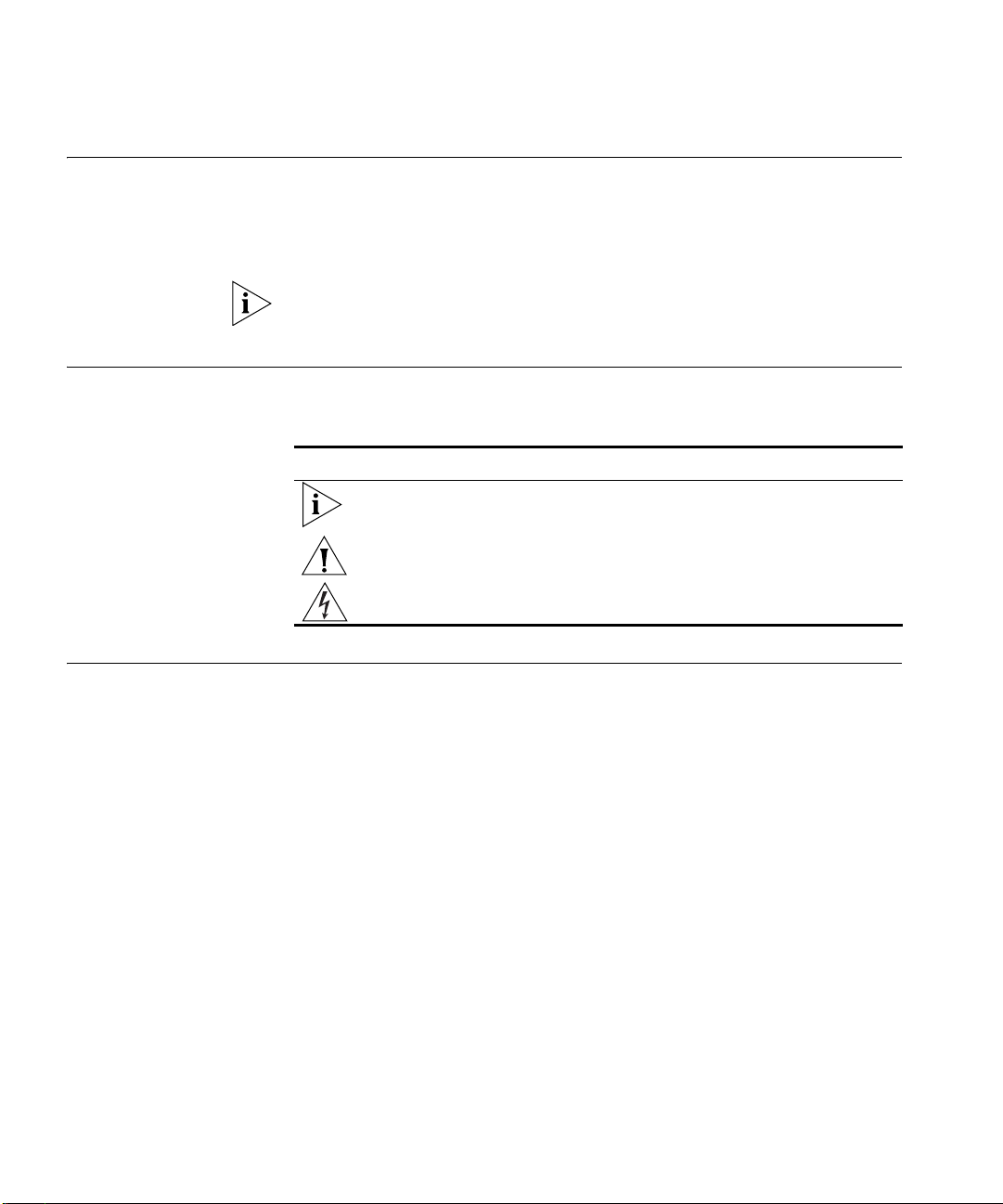
Unit LED
Console Port
Mode LED
Power LED
10/100BASE-TX Ports
Port Status LEDs
1000BASE-X Ports
RPS LED
Unit LED
Console Port
Mode LED
RPS LED
10/100BASE-TX Ports
Port Status LEDs
1000BASE-X Ports
PWR LED
Unit LED
Console Port
Mode LED
Power LED
10/100BASE-TX Ports
Port Status LEDs
1000BASE-X Ports
RPS LED
3CR17171-91
SuperStack 4 Switch 5500 PWR 28 Port
Green=Status
Yellow=Packet
Red=PoE
Switch 5500 Family
— Front View
Figure 1 Switch 5500-SI and EI 28-Port — front view
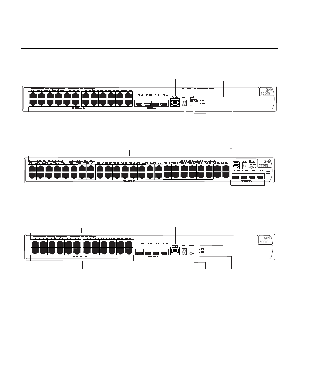
Figure 2 Switch 5500-SI and EI 52-Port — front view
Figure 3 Switch 5500-EI 28-Port PWR - front view
Page 15
Switch 5500 Family — Front View 15
Unit LED
Console Port
Mode LED
RPS LED
10/100BASE-TX Ports
Port Status LEDs
1000BASE-X Ports
PWR LED
SuperStack 4 Switch 5500 PWR 52 Port
3CR17172-91
Green=Status
Yellow=Packet
Red=PoE
RPS
PWR
Green=Speed
Yellow=Duplex
Speed Duplex
100Base-FX
1000Base-X
Console Port
Two 10/100/1000BASE-T Ports
Two 1000BASE-X Ports
Unit LED
RPS LED
Power LED
Mode LED
Port Status LEDs
100BASE-X Ports
10/100/1000BASE-T Ports
Console Port
3CR17251-91 SuperStack4 Switch 5500G-EI 24-Port
Port Status LEDs
Unit LED
21
22 23
24
Dual Personality
10/100/1000BASE-T/
1000BASE-X SFP Ports
1 432 5 678 9 10 11 1213 161514 17 18 19 20 21 22 23 24
Console
PWR
RPS
MOD
STK
Unit
Stack LED
Module LED
RPS LED
Status:Green=10Mbps Yellow=10MbpsFlashing=Disabled Packet:Green=Full Duplex Yellow=Half Duplex Power:Green=Delivering Power Yellow=FaultFlashing Green=Over Budget
100%
80%
60%
40%
20%
Mode:
Green=Status
Yellow=Packet
Red=POE
Mode LED
PWR LED
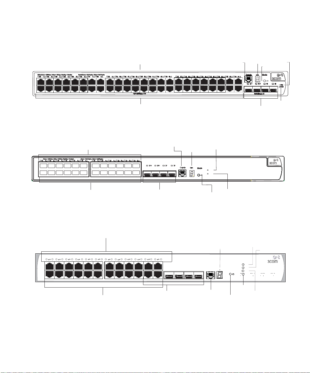
Figure 4 Switch 5500-EI 52-Port PWR - front view
Figure 5 Switch 5500-EI FX 28-Port — front view
Switch 5500G-EI Figure 6 Switch 5500G-EI (24 port) — front view
Page 16
16 CHAPTER 1: INTRODUCING THE SWITCH 5500 FAMILY
10/100/1000BASE-T Ports
Console Port
SuperStack 4 Switch 5500G-EI 48-port
Port Status LEDs
Unit LED
45
46 47
48
Dual Personality
10/100/1000BASE-T/
1000BASE-X SFP Ports
1 432 5 678 9 10 11 1213 161514 17 18 19 20 21 22 23 24 25 282726 29 30 31 32 33 34 35 3637 403938 41 42 43 44 45 46 47 48
Status:Green=10Mbps Yellow=10MbpsFlashing=Disabled Packet:Green=Full Duplex Yellow=Half Duplex Power:Green=Delivering Power Yellow=FaultFlashing Green=Over Budget
PWR
RPS
MOD
STK
100%
80%
60%
40%
20%
Mode:
Green=Status
Yellow=Packet
Red=POE
Stack
LED
Mode LED
Power LED
RPS LED
Module LED
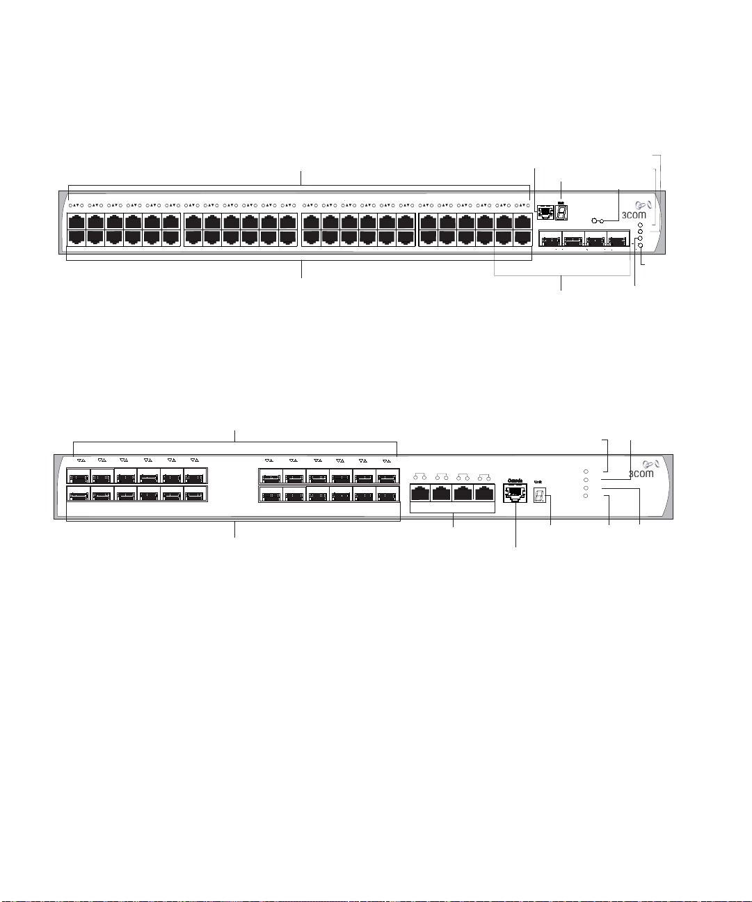
Unit LED
Console Port
10/100/1000BASE-TX Ports
Port Status LEDs
1000BASE-X Ports
1
13
3CR17259-91 SuperStack 4 Switch 5500G-EI SFP 24-Port
PWR
RPS
MOD
STK
11
23
10
22
8
20
7
19
12
24
9
21
6
18
5
17
4
16
3
15
2
14
1000BASE-X:
Green=1000Mbps Flashing Yellow=POST failed
10/100/1000BASE-TX:
S(Speed):Green=1000Mbps Yellow=10/100Mbps
D(Duplex):Green=Full Duplex Yellow=Half Duplex
Mode
LED
Stack
LED
RPS LED
Power LED
10/100/1000Base-TX
1000Base-X1000Base-X
S
D
25/11
S
D
26/12
S
D
27/23
S
D
28/24
Figure 7 Switch 5500G-EI (48 port) — front view
Figure 8 Switch 5500G-EI SFP (24 port) — front view
WARNING: The RJ-45 ports are shielded RJ-45 data sockets. You cannot
use them as standard traditional telephone sockets, or to connect the
unit to a traditional PBX or public telephone network. Only connect RJ-45
data connectors, network telephony systems, or network telephones to
these sockets. You can connect either shielded or unshielded data cables
with shielded or unshielded jacks to these data sockets.
10BASE-T/
100BASE-TX/
1000BASE-T Ports
The 10BASE-T/100BASE-TX/1000BASE-T ports have RJ-45 connectors and
are configured as Auto MDIX (cross-over).
The default state for these ports is auto-negotiation enabled, where the
link’s speed, duplex, and flow control modes are automatically detected
to provide the highest available bandwidth with the link partner.
Page 17

Switch 5500 Family — Front View 17
You can disable auto-negotiation. You can manually configure these
ports to 10 Mbps half duplex, 100 Mbps half duplex,
10 Mbps full duplex, or 100 Mbps full duplex. It is not possible to
manually configure a 1000 Mbps link because auto-negotiation is
mandatory in the 1000 Mbps standard. If you disable auto-negotiation,
Auto MDIX cannot function and the ports become fixed in MDIX
(cross-over) mode.
If you disable auto-negotiation on a 1000 Mbps port, the speed drops to
the highest available speed, which is 100 Mbps by default.
1000BASE-X SFP Ports The 1000BASE-X SFP (Small Form Factor Pluggable) ports support fiber
Gigabit Ethernet short-wave (SX), long-wave (LX), long-haul (LH70), and
copper (T) SFP Transceivers in any combination. This offers you the
flexibility of using SFP transceivers to provide connectivity between the
Switch and remote 1000 Mbps workgroups, or to create a high capacity
aggregated link backbone connection.
The default state for these ports is auto-negotiation enabled, where the
speed, duplex and flow control modes are negotiated. As the speed and
duplex modes are fixed by the media type, only the flow control is
negotiated with the link partner. Alternatively, auto-negotiation can be
disabled (except 1000BASE-T where auto-negotiation is mandatory) and
the flow control setting can be manually configured.
100BASE-X SFP Ports
(Switch 5500-EI FX
only)
Console Port The console port allows you to connect a terminal and perform remote or
You can also use these ports for stacking the 5500 SI and EI. For
information about stacking these switches, see the section entitled
“Guidelines For Interconnecting Units” on page 78.
The Switch 5500-EI FX has 24 100BASE-X SFP ports. These are 100Mbps
ports that can use multi-mode fiber optic cables of up to 2km and
single-mode fiber optic cables of up to 10km.
You must manually configure duplex and flow control.
The Switch 5500-EI FX supports copper transceivers on the Gigabit SFP
ports only.
local out-of-band management. As the console port on the Switch is an
RJ-45 port, you must connect an RJ-450 to DB9 converter cable to a
standard null modem cable in order to connect a terminal.
Page 18

18 CHAPTER 1: INTRODUCING THE SWITCH 5500 FAMILY
Unit LED The Unit LED is a seven segment display visible on the front of the Switch.
The Unit LED indicates the unit number in a fabric, POST test ID, and
software upgrade information. In the unlikely event of a hardware fault
occurring, you can use the Unit LED to help diagnose the problem. For
information on using the Unit LED for problem solving, see
Problems Indicated by LEDs” on page 82.
LEDs Ta bl e 5 lists the LEDs visible on the front of the Switch, and how to read
their status according to color. For information on using the LEDs for
problem solving, see
page 43.
Ta bl e 5 LED behavior
LED Color Indicates
10/100/1000BASE-TX Port LEDs
Speed Green A high speed (1000 Mbps) link is present, blinking off
Yellow A low speed (10/100 Mbps) link is present, blinking
Yellow flashing The port has failed POST.
Off No link is present.
Duplex Green Full duplex, blinking off for every packet received or
Yellow Half duplex, blinking off for every packet received or
Yellow flashing The port has failed POST.
Off No link is present.
PoE Green Power is being delivered to the port.
Green flashing Port power has exceeded limit or is unable to supply
Yellow PoE error, no power supplied on port.
Yellow flashing The port has failed post.
Off No power is being delivered.
10/100BASE-T/TX Ports LEDS
Speed Green A high speed (100 Mbps) link is present, blinking off
Yellow A low speed (10 Mbps) link is present, blinking off for
Yellow flashing The port has failed POST.
“Solving
“Checking for Correct Operation of LEDs” on
for every packet received or transmitted.
off for every packet received or transmitted.
transmitted.
transmitted.
power due to unit being over budget.
for every packet received or transmitted.
every packet received or transmitted.
Page 19

Switch 5500 Family — Front View 19
LED Color Indicates
Off No link is present.
Duplex Green Full duplex, blinking off for every packet received or
transmitted.
Yellow Half duplex, blinking off for every packet received or
transmitted.
Yellow flashing The port has failed POST.
Off No link is present.
PoE Green Power is being delivered to the port.
Green flashing Port power has exceeded limit or is unable to supply
power due to unit being over budget.
Yellow PoE error, no power supplied on port.
Yellow flashing The port has failed post.
Off No power is being delivered.
1000BASE-X SFP Port LEDs
Speed Green A 1000 Mbps link is present.
Yellow flashing The port has failed post.
Off No link is present.
Duplex Green Full duplex packets are being transmitted/received on
Yellow Half duplex packets are being transmitted/received on
Yellow flashing Port failed POST.
Off No links is present.
100BASE-X SFP Port LEDs
Speed Green A 100 Mbps link is present.
Yellow flashing The port has failed post.
Off No link is present.
Duplex Green Full duplex packets are being transmitted/received on
Yellow Half duplex packets are being transmitted/received on
Yellow flashing Port failed POST.
Off No links is present.
the port.
the port.
the port.
the port.
Page 20

20 CHAPTER 1: INTRODUCING THE SWITCH 5500 FAMILY
LED Color Indicates
Unit LED
Green Power on Self Test (POST) is in progress. During POST
Green flashing The Switch has failed POST. The Unit LED flashes the
Green flashing ‘f’ There has been a fan failure.
Green flashing ‘t’ The Switch is over temperature and unit temperature
Stack LED
Green The XRN stack is functioning in resilient mode. Loop
Green flashing Switch is not compatible with the other Switches in
Yellow The XRN stack is functioning without the loop
Off Stacking Cables are not connected.
Module LED (Switch 5500G-EI only)
Green The Module is installed and operating normally.
Yellow flashing The Module is installed but not supported or faulty.
Off The Module is not installed.
Mode LED
Duplex Yellow 10/100/1000 Duplex and Activity, 1000 SFP Duplex
Speed Green 10/100/1000 Port Speed and Activity, 1000 SFP
PoE Red 10/100/1000 port showing PoE information.
RPS LED
Green AC and RPS supply connected.
Yellow AC failed or not connected. RPS supply is OK.
Off There is no RPS supply connected.
a test ID number appears in the Unit LED (seven
segment display)
or
Software download is in progress. During software
download, a clockwise cycling bar appears in the Unit
LED.
number of the test that has failed.
is critical.
cable is attached.
the stack.
connection.
and Activity, or Stack Activity.
Status and Activity, or Stack Status and Activity.
Page 21
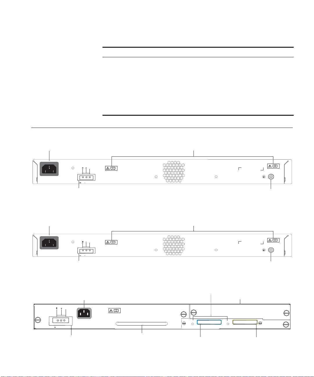
LED Color Indicates
Power Socket
Redundant Power System Socket
100-240V; 50/60Hz; 2.5A
Open Book Warning Labels
NULL
Earthing Screw
~
-48 -60V;2.0A
Power Socket
Redundant Power System Socket
100-240V; 50/60Hz; 8.0A
Open Book Warning Labels
NULL
Earthing Screw
~
-53 -55V;19.5A
Redundant Power System Socket
Power Socket
Stacking Cable Port (Down)
Stacking Cable Port (Up)
Expansion Module Slot
Stacking: Green=OK, Flashing Green=Traffic,Yellow=Link Fault,
YellowFlashing=Stack Fault
Stack LEDs
Handle
-52 - -55V;19.5A
DOWN
UP
Switch 5500G PoE PSU 24-Port
NULL
PWR LED
Green The Switch is powered-up and operating normally.
Green flashing Self Test (POST) or Software Download is in progress.
Yellow flashing One or more ports have failed POST.
Red The Switch has failed its Power On Self Test.
Off The Switch is not receiving power or there is a fault
with the Power Supply Unit.
Switch 5500 — Rear View Detail 21
Switch 5500 — Rear
Figure 9 Switch 5500-SI, EI and FX — rear view
View Detail
Figure 10 Switch 5500-EI PWR - rear view
Switch 5500G-EI Figure 11 Switch 5500G-EI — rear view
Page 22
22 CHAPTER 1: INTRODUCING THE SWITCH 5500 FAMILY
Expansion Module
Slot (Switch 5500G-EI
Only)
You can use this slot to install an Expansion Module. The Switch 5500G
Family provides one expansion module slot on the rear panel in which you
can use an 8-port 1000 Mbps SFP module, a 1-port 10 Gbps XENPAK
module, or a 2-port 10 Gbps XFP module.
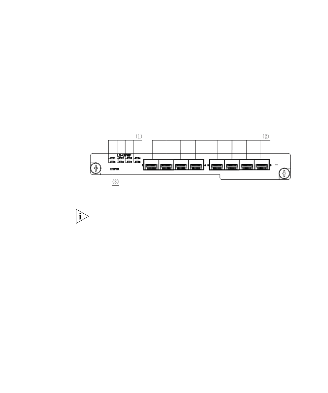
8-port 1000 Mbps SFP module
This module, shown in Figure 12, provides eight 1000 Mbps 1000Base-X
SFP transceiver ports.
Figure 12 8-port 1000 Mbps SFP module
(1) Port status LEDs 2) SFP ports 3) Module power LED
Notes:
■ The types of available SFP modules may change over time. Refer to
www.3com.com for the latest transceiver support.
■ For SFP module specifications, refer to 3Com Web site at
www.3com.com
2-port 10 Gbps XFP module
This module, shown in Figure 13, provides two 10 Gbps XFP optical ports.
Page 23
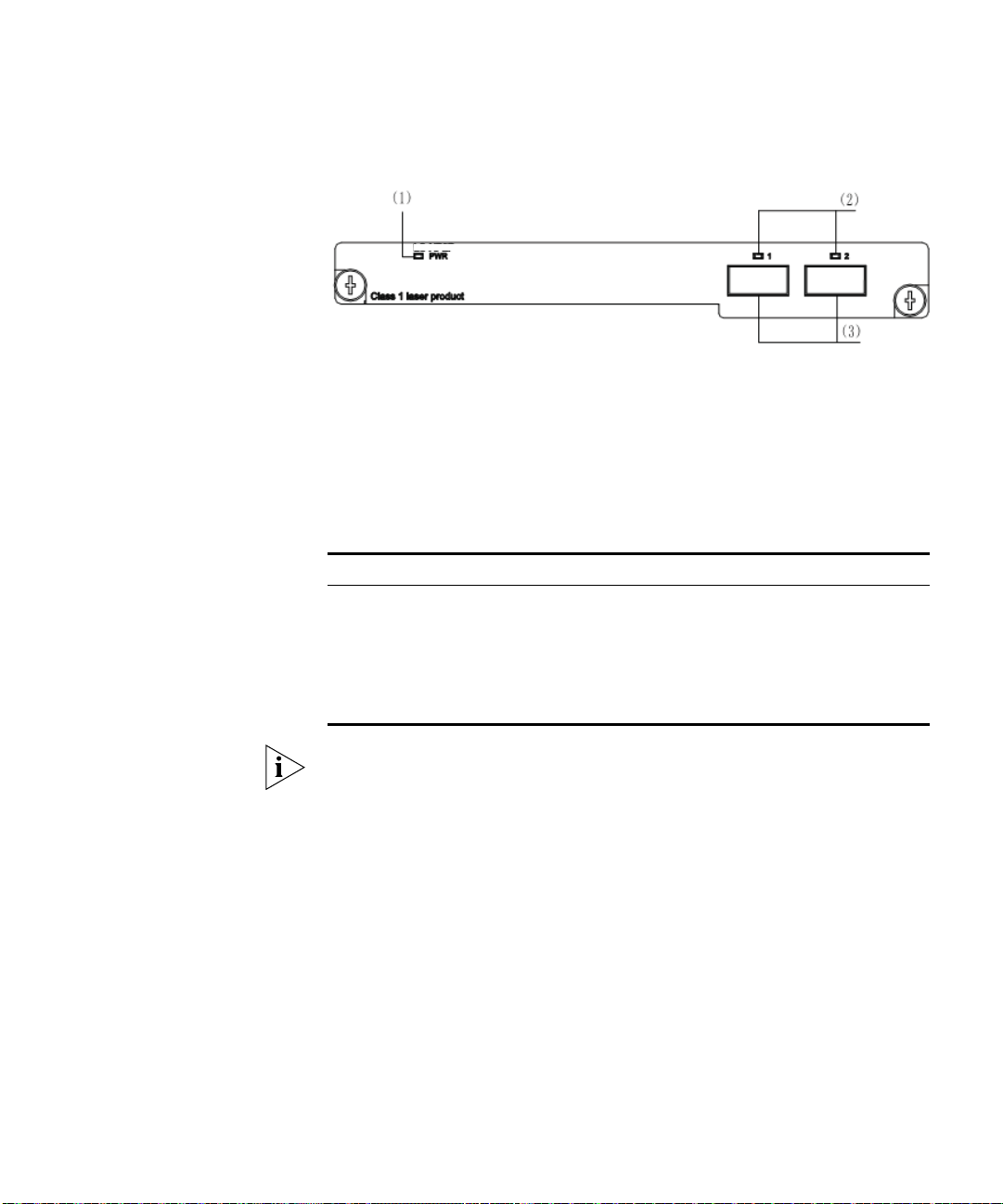
Figure 13 2-port 10 Gbps XFP module
Switch 5500 — Rear View Detail 23
(1) Module power LED (2) 10 Gbps XFP optical
ports
(3) 10 Gbps XFP optical ports
Ta bl e 6 lists the available XFP transceivers.
Ta bl e 6 XFP transceivers supported by 2-port 10 Gbps XFP module
Ty pe Model
XFP transceivers 3CXFP90 10GBASE-LRM
3CXFP92 10GBASE-LR
3CXFP94 10GBASE-SR
3CXFP95 10GBASE-CX4
3CXFP96 10GBASE-ER
Notes:
■ The type of 10 Gbps XFP module may be different from those listed
above. For the most up-to-date information, refer to www.3com.com.
■ For XFP transceiver specifications, refer to 3Com’s Web site at
www.3Com.com.
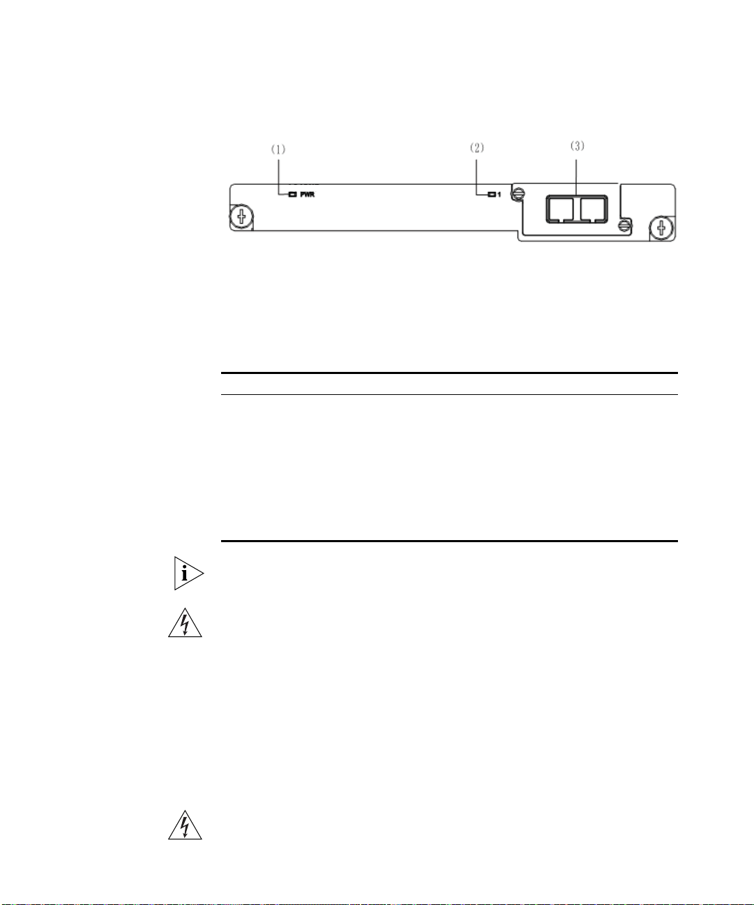
1-port 10 Gbps XENPAK module
This module, shown in Figure 14, provides one 10 Gbps XENPAK
transceiver port.
Page 24
24 CHAPTER 1: INTRODUCING THE SWITCH 5500 FAMILY
Figure 14 1-port 10 Gbps XENPAK module
(1) Module power
LED
(2) Port status LED (3) 10 Gbps XENPAK
optical/electrical port
The Table 7 lists the available XENPAK optical modules:
Ta bl e 7 XENPAK optical port module supported by 1-port 10 Gbps XENPAK
module
Ta bl e 8 Typ e Ta bl e 9 Model
XENPAKs that are supported
3CXENPAK91 10GBASE-LX4
3CXENPAK92 10GBASE-LR
XENPAK optical module
3CXENPAK93 10GBASE-T
3CXENPAK94 10GBASE-SR
3CXENPAK95 10GBASE-CX4
3CXENPAK96 10GBASE-ER
For specifications of XENPAK Transceivers, refer to 3Com’s Web site at
www.3Com.com.
WARNING: When an Expansion Module is not installed, ensure that the
blanking plate is fitted by tightening all screws with a suitable tool.
Failure to fit a blanking plate may void the product warranty.
Power Socket The Switch automatically adjusts its power setting to any supply voltage
Open Book Warning
Labels
in the range 100-240 VAC.
Before installing or removing any components from the Switch 5500
Family or carrying out any maintenance procedures, you must read the
safety information provided in
Appendix A of this guide.
AVERTISSEMENT: Avant d'installer ou d'enlever tout composant des
commutateurs de la gamme Switch 5500 ou d'entamer une procédure
Page 25

Switch 5500 — Rear View Detail 25
de maintenance, lisez les informations relatives à la sécurité qui se
trouvent dans l'annexe A de ce guide.
VORSICHT:Bevor Sie Komponenten der Switch 5500-Baureihe
installieren oder deinstallieren und bevor Sie Wartungsarbeiten
ausführen, müssen Sie die in Anhang A dieses Handbuchs aufgeführten
Sicherheitshinweise lesen.
ADVERTENCIA: Antes de instalar o extraer cualquier componente del
Switch 5500 Family o de realizar tareas de mantenimiento, debe leer la
información de seguridad facilitada en el Apéndice A de esta guía.
Page 26

26 CHAPTER 1: INTRODUCING THE SWITCH 5500 FAMILY
AVVERTENZA: Prima di installare o rimuovere qualsiasi componente
dello Switch 5500 Family o di eseguire qualsiasi procedura di
manutenzione, leggere le informazioni di sicurezza riportate
nell'Appendice A di questa guida.
OSTRZEŻENIE: Przed instalacją lub usunięciem jakichkolwiek elementów
z przełącznika z rodziny 5500 lub przeprowadzeniem prac
konserwacyjnych należy zapoznać się z informacjami o bezpieczeństwie
zawartymi w Załączniku A niniejszego podręcznika.
Redundant Power
System Socket
Stacking Cable Ports
(Switch 5500G-EI)
For protection against an internal power supply failure, you can use this
socket to connect the Switch to a -48 DC Redundant Power System.
You can use these ports to connect the following cables:
■ Stacking Cable (3C17262) — this cable enables you to stack together
two switches up to three rack units apart.
■ Resilient Stacking Cable (3C17263) — this cable enables you to stack
together two switches up to sixteen rack units apart.
You can stack together any combination of 5500G-EI 24 port and 48 port
units, up to a maximum of eight units.
For more information on how to connect a stacking cable to your Switch
units, refer to the Installation Guide that accompanies your cable.
You canno create a Fabric by interconnecting a 3Com Switch 5500G with
any other 3Com device (such as a 5500-EI) or mix Enhanced Image (EI)
Switch 5500 units with Standard Image (SI) units.
Page 27

Default Settings 27
Default Settings Ta bl e 10 shows the default settings for the Switch 5500 Family:
Ta bl e 10 Default Settings
Feature Switch 5500
Automatic IP Configuration Enabled
Port Status Enabled
Port Speed Auto-negotiated
Duplex Mode Auto-negotiated
Power over Ethernet Enabled (3CR17171-91 and 3CR17172-91 only)
Flow Control Auto-negotiated
Broadcast Storm Control Enabled
Virtual LANs (VLANs) All ports belong to the untagged Default VLAN
(VLAN
1) with IEEE Std 802.1Q-1998 learning
operational
Management VLAN Fixed as VLAN 1 on 5500-SI units. Can be any
VLAN for 5500-EI/5500G-EI units.
Link Aggregation Control
Protocol (LACP)
IP Multicast Filtering Filtering enabled
Rapid Spanning Tree Protocol Enabled
Fast Start Enabled on front panel ports
RMON Alarm Enabled
Webcache Support Disabled
Traffic Prioritization All ports prioritize NBX VoIP traffic (LAN and IP).
Port Security Disabled per port
Configuration Save and
Restore
Spanning Tree Protocol Enabled
Smart Auto-sensing Enabled
Disabled per port
All ports set to “best effort” for all other traffic.
Disabled
Page 28

28 CHAPTER 1: INTRODUCING THE SWITCH 5500 FAMILY
Page 29

2
INSTALLING THE SWITCH
This chapter contains the information you need to install and set up the
Switch 5500. It covers the following topics:
■ Package Contents
■ Choosing a Suitable Site
■ Rack-mounting
■ Connecting a Redundant Power Supply
■ Placing Units On Top of Each Other
■ The Power-up Sequence
■ SFP Operation
■ Packing and Shipping the Switch 5500
WARNING: Safety Information. Before installing or removing any
components from the Switch 5500 or carrying out any maintenance
procedures, you must read the safety information provided in Appendix
of this guide.
A
AVERTISSEMENT: Consignes de sécurité. Avant d'installer ou d'enlever
tout composant du Switch 5500 ou d'entamer une procédure de
maintenance, lisez les informations relatives à la sécurité qui se trouvent
dans l'Appendice A de ce guide.
VORSICHT: Sicherheitsinformationen. Bevor Sie Komponenten aus
dem Switch 5500 entfernen oder dem Switch 5500 hinzufuegen oder
Instandhaltungsarbeiten verrichten, lesen Sie die Sicherheitsanweisungen,
die in Appendix A (Anhang A) in diesem Handbuch aufgefuehrt sind.
ADVERTENCIA: Información de seguridad. Antes de instalar o extraer
cualquier componente del Switch 5500 o de realizar tareas de
mantenimiento, debe leer la información de seguridad facilitada en el
Apéndice A de esta guía del usuario.
Page 30

30 CHAPTER 2: INSTALLING THE SWITCH
AVVERTENZA: Informazioni di sicurezza. Prima di installare o
rimuovere qualsiasi componente dal Switch 5500 o di eseguire qualsiasi
procedura di manutenzione, leggere le informazioni di sicurezza riportate
nell'Appendice A della presente guida per l'utente.
OSTRZEŻENIE: Informacje o zabezpieczeniach. Przed instalacją lub
usunięciem jakichkolwiek elementów z product lub przeprowadzeniem
prac konserwacyjnych należy zapoznać się z informacjami o
bezpieczeństwie zawartymi w Załączniku A niniejszego podręcznika.
Package Contents The Switch 5500 packaging contains the following for all units:
■ Switch unit
■ Release Notes
■ RPS -48V DC Connector
■ Unit Information Labels
■ Warranty Information
■ RPS Flyer
■ Power Cord
■ Console Cable (RJ-45)
■ RPS Connector (and backshell)
■ RPS Connector Cable Tie
■ Earthing Lead
■ Mounting brackets
■ Screws
■ 4 x Rubber feet
Ta bl e 11 below details the packaging contents specific to each unit in the
Switch 5500 Family.
Page 31

Choosing a Suitable Site 31
Ta bl e 11 Package Contents
Switch 5500-SI 28 and 52 Port
Switch 5500-EI 28 and 52 Port
Switch 5500 PWR 28 and 52 Port
Switch 5500 FX 28 Port
Switch 5500G-EI 24 Port
Blanking Plate ✓ ✓ ✓
12A RPS Connector and Backshell
(incl. cable tie and earthing lead)
✓ ✓ ✓
Switch 5500G-EI 48 Port
Switch 5500G-EI SFP 28 Port
Choosing a Suitable Site
25A RPS Connector and Backshell
(incl. cable tie and earthing lead)
2 x Front Securing Brackets ✓ ✓ ✓ ✓ ✓ ✓ ✓
2 x Back Securing Brackets ✓ ✓ ✓ ✓
4 x Screws ✓ ✓ ✓
6 x Screws ✓ ✓ ✓ ✓
✓ ✓ ✓ ✓
The Switch 5500 Family is suited for use in an internal wiring closet, a
network room, or telecommunications room, where you can mount it in a
standard 19-inch equipment rack or leave it free-standing.
CAUTION: Ensure that the ventilation holes are not obstructed.
When deciding where to position the switch, ensure that:
■ The cabling is located away from:
■ sources of electrical noise, such as radios, transmitters, and
broadband amplifiers.
■ power lines and fluorescent lighting fixtures.
■ The switch is accessible and cables can be connected easily.
■ Water or moisture cannot enter the switch’s case.
Page 32

32 CHAPTER 2: INSTALLING THE SWITCH
■ Air flow is not restricted around the switch or through the vents in the
■ The air temperature around the switch does not exceed 40 °C (104
If the switch is installed in a 19-inch rack or closed assembly, its local air
temperature may be greater than room ambient temperature.
■ The air is as free from dust as possible.
■ The switch is situated away from conductive (electrical) dust sources;
■ The unit is installed in a clean, air conditioned environment.
■ The AC supply used by the switch is separate from the AC supply used
■ No more than four switch units are placed on top of one another if
side of the switch. 3Com recommends that you provide a minimum of
25 mm (1 in.) clearance.
°F).
laser printers, for example.
by units that generate high levels of AC noise; air conditioning units,
for example.
the units are free-standing.
Rack-mounting The Switch 5500 is 1U high and will fit in most standard 19-inch racks.
CAUTION: Disconnect all cables from the switch before continuing.
Remove all self adhesive pads from the underside of the switch if they
have been fitted.
CAUTION: If you use a shelf or support, ensure that it will not obstruct
the air flow through the switch’s side panels.
Switch 5500 (non
PoE)
To rack-mount your Switch 5500 (non PoE):
1 Place the switch the right way up on a hard flat surface with the front
facing towards you.
2 Place a securing bracket over the mounting holes on one side of the front
of the switch, as shown in
Figure 15.
Page 33

Rack-mounting 33
3 Insert the two screws and tighten them with a suitable screwdriver.
Figure 15 Fitting a front bracket for rack-mounting
You must use the screws supplied with the securing brackets. Damage
caused to the unit by using incorrect screws invalidates your warranty.
4 Repeat steps 2 and 3 for the other side of the switch.
5 Insert the switch into the 19-inch rack and secure with suitable screws
(not provided). Ensure that the ventilation holes are not obstructed.
6 Connect the network cabling.
7 Place a unit information label on the unit in an easily accessible position.
The unit information label shows the switch’s:
■ 3Com product name
■ 3Com 3C number
■ Unique MAC address (Ethernet address)
■ Serial number
You may need this information if you contact 3Com for Technical
Support.
Page 34

34 CHAPTER 2: INSTALLING THE SWITCH
Switch 5500 and
Switch 5500G-EI (PoE)
To rack-mount the front of your Switch 5500 and Switch 5500G-EI (PoE):
1 Place the switch the right way up on a hard flat surface, with the front
facing towards you.
2 Place a securing bracket over the mounting holes on one side of the front
of the switch, as shown in
Figure 15.
3 Insert the two screws and tighten them with a suitable screwdriver.
4 Repeat steps 1 and 2 for the other front securing bracket.
You must use the screws supplied with the securing brackets. Damage
caused to the unit by using incorrect screws invalidates your warranty.
5 Insert the switch into the 19-inch rack and secure with suitable screws
(not provided). Ensure that the ventilation holes are not obstructed.
To rack mount the rear of your switch:
1 Place a rear rail bracket over the mounting holes on one side of the rear
of the switch, as shown in
Figure 16.
The bracket has two mounting positions. The one you choose depends
on the rack depth.
Ta bl e 12 describes the correct positions on which to
mount the bracket:
Ta bl e 12 Rear rail bracket mounting points
Distance from Front to Rear Mounting Positions
37cm — 25cm Middle mounting point
43cm — 56cm Rear mounting point
2 Insert the screw and tighten it with a suitable screwdriver.
3 Repeat steps 1 and 2 for the other rear securing bracket.
Page 35

Connecting a Redundant Power Supply 35
Figure 16 Fitting a rear rail bracket for rack-mounting
4 Insert the switch into the 19-inch rack and secure it with suitable screws
(not provided). Ensure that the ventilation holes are not obstructed.
Connecting a Redundant Power Supply
5 Connect the network cables.
6 Place a unit information label on the unit in an easily accessible position.
The unit information label shows the switch’s:
■ 3Com product name
■ 3Com 3C number
■ Unique MAC address (Ethernet address)
■ Serial number
You may need this information if you contact 3Com for Technical
Support.
The Switch 5500 Family has a -48V DC Redundant Power Supply socket.
WARNING: Only properly trained and qualified personnel should install
the Redundant Power Supply (RPS).
WARNING: Make sure to read these instructions in conjunction with the
RPS flyer and the safety and installation instructions supplied with your
RPS.
Page 36

36 CHAPTER 2: INSTALLING THE SWITCH
WARNING: When powering any Switch 5500 from an RPS, make sure
that the unit is earthed (grounded) by either connecting the power cord
to the unit or by connecting the earth terminal on the rear of the unit to
a reliable electrical earth (or by connecting both). Ensure that the earth
connection is made before connecting the DC supply from the RPS.
3Com switches that support -48V DC RPS inputs, and are PoE enabled,
can only be powered by an RPS that complies with the isolation
requirements of IEEE-Std 802.3af. Non PoE enabled switches do not have
this restriction.
WARNING: Do not use a standard 'positive-earthed' -48V redundant
power system suitable for use with telecommunications equipment with
the 3Com Power-over-Ethernet (PoE) network switches. In order to meet
the IEEE 802.3af (PoE) specification, the -48V output must be isolated
from earth (ground) and meet the isolation requirements in that
specification.
WARNING: Any RPS must be approved as a SELV output in accordance
with IEC 60950-1/UL 60950-1/EN 60950-1.
WARNING: The characteristics of the Switch 5500 DC supply input are
provided in Appendix C on page 127.
You can power the Switch 5500 using three methods:
■ AC Mains only — this does not offer any power redundancy. If the
AC mains supply or the AC power supply fails, the switch powers off.
■ AC Mains and -48V DC (primary supply) — the internal AC supply
acts as the backup in the event of a DC power failure.
■ DC only — the switch does not need an AC supply and the resiliency
is provided by the DC supply. This is useful in environments where only
DC power is available.
The RPS provides three main benefits:
■ Power Redundancy — if a switch is powered from the mains supply
unit, a failure of the internal power supply causes the switch to fail.
You can avoid this by connecting both the AC and DC RPS supplies to
the switch. You can also add redundancy to the DC power by using
(N+1) DC power supplies to further increase the availability of the
system.
Page 37

Connecting a Redundant Power Supply 37
■ Uninterruptable Power — the system allows easy connection and
maintenance of batteries to the RPS shelf to further increase the
availability of the system.
■ Additional Power to PoE Ports — the PoE switch’s internal AC
Power Supply provides enough power for most network applications.
You can use the RPS to supplement power (up to a maximum of
15.4W), including full backups of all PoE devices on the network.
Ta bl e 13 outlines the behavior of the switch when changes occur to the
power system, such as removing the AC mains cable when the RPS is
attached. The responses to the different power inputs are controlled by
the switch’s internal power supply and not by the RPS.
Ta bl e 13 Switch Power Inputs
Power Input before
User Intervention
AC mains and RPS RPS only The unit remains powered by the RPS.
AC mains and RPS AC mains only The unit is powered by the AC mains.
RPS only AC mains and RPS The unit remains powered by the RPS.
AC mains AC mains and RPS The unit is powered by the RPS. Full
Power Input after
User Intervention
Correct Response
PoE is dropped on all ports, however
the unit does not reset. PoE restarts
and is powered by the remaining
power from the AC mains. PoE ports
will be dropped depending on their
preset priority level.
The total power available to the
switch may be less than when
powered from the RPS. Some PoE
ports may be dropped because they
are unable to obtain the power they
require.
PoE power can be enabled on all
ports.
Page 38

38 CHAPTER 2: INSTALLING THE SWITCH
Specifying the
Redundant Power
System
3Com’s redundant power solution allows you to use any off-the-shelf
-48V DC RPS that meets the requirements defined in
Appendix C on
page 127.
For an approved vendor list, more details about purchasing the 3Com
recommended RPS, and a full set of requirements go to:
http://www.3Com.com/RPS
The 3Com recommended RPS generates -48V DC power using power
supply units (or rectifiers). The outputs of the rectifier(s) are connected
together so that you can increase the total -48V power available by
adding rectifiers. For example, three 1500W rectifiers can provide up to
4500W. Hot removal or insertion of a rectifier does not affect the -48V
DC output voltage.
Ta bl e 14 shows an example of the total power available from several
1500W rectifiers.
A minimum of two rectifiers are required for each shelf to provide N+1
rectifier redundancy.
Ta bl e 14 Power Availability
Rectifiers
1 2 3 4 5 6
No Rectifier
Redundancy
N+1 Rectifier
Redundancy
1500W 3000W 4500W 6000W 7500W 9000W
- 1500W 3000W 4500W 6000W 7500W
The unearthed -48V DC power distribution provides the mechanism to
connect to the Switch 5500. The distribution consists of several circuit
breakers and connection terminals for the positive (common) and
negative -48V outputs. Individually connect each Switch 5500 to a circuit
breaker terminal.
You can also connect a battery to battery terminals prior to the DC power
distribution to provide uninterrupted power and to be protected against
the loss of AC mains power.
Page 39

Connecting a Redundant Power Supply 39
3Com’s RPS solution uses -48V DC power distribution. The RPS system
provides bulk -48V DC power that is separately distributed to a number
of network switches.
Each RPS consists of a shelf that can house from one to six rectifiers, a
Distribution Module, and a Management Module.
Connecting the
Switch to the
Redundant Power
System
When connecting the RPS to the switch, the circuit breaker and 2-core
cables need to be matched to the switch’s power rating.
Ta bl e 15 shows
the recommended circuit breaker and cable rating for the Switch 5500.
The recommended cable length should not exceed three metres (9.84
feet).
Ta bl e 15 Switch 5500 Circuit Breaker and Cable Ratings
Circuit Breaker Minimum 2-Core Cable Diameter
Non PoE 6A C type 18 AWG (solid or stranded cable)
PoE 25A C type 12 AWG (solid or stranded cable)
WARNING: Make sure to follow the RPS Manufacturers
recommendations when connecting the cable to the RPS.
WARNING: Ensure that the circuit breaker in the RPS is in the open (off)
position when connecting the cable to the RPS and the cable and
connector to the switch.
WARNING: You must ensure that the positive terminal on the switch is
connected to the positive (common) terminal of the RPS and that the
negative terminal on the switch is connected to the negative (circuit
breaker) terminal of the RPS.
Figure 17 shows how to connect the power supply to the RPS socket in
the back of the switch. Use the cable tie supplied with your switch to
support the cable in the back of the RPS connector as shown in
Figure 17.
Page 40

40 CHAPTER 2: INSTALLING THE SWITCH
+
-
NULL
-48 -60V;2.0A
100-240V;50/60Hz;1.0A
~
NULL
-48 -60V;2 0A
Null
+
-
Pinout
Cable Tie
Figure 17 RPS Connection to the Switch
Connecting the
Earthing Cable
When the RPS is connected to the switch, you can move the circuit
breaker in the RPS to the closed (on) position and the switch will be
powered by the -48V DC power.
The -48V DC power takes priority over the AC mains and powers the
switch if it is connected.
Use the earthing cable that accompanies your switch if the length is
suitable. Alternatively use the earthing cable specification as defined in
Appendix C on page 127.
The earthing cable is only required if the switch is powered by the RPS
only.
The recommended cable length should not exceed three metres (9.84
feet).
Page 41

Connecting a Redundant Power Supply 41
RPS LED The RPS status LED on the front of the Switch 5500 indicates the status of
the RPS and AC supplies as shown in
Ta bl e 16 RPS LED Colors
Color State
Green The AC and RPS supply is connected.
Yellow The AC supply has failed or is not connected. The RPS
supply is connected.
Off There is no RPS supply connected.
Ta bl e 16.
Using Power over
Ethernet
The Switch 5500G-EI Power over Ethernet (PoE) units can supply power
to any IEEE 802.3af compliant device through any of its front panel ports
over a Category 5 or Category 5e Ethernet cable. The same cable
connects the device to the network.
The Switch 5500 units can supply power through the 10/100 ports only.
Power over Ethernet is a self-configuring protocol. When you plug a PoE
compliant device into one of the ports on the switch, the switch supplies
the power required to the device, providing that the total power budget
for the switch is not exceeded.
A PoE switch combines the functionality of a standard Ethernet switch
with a single power supply that can power multiple devices. Using a PoE
switch has the following advantages over an non-powered network.
■ Reduced Cabling — a PoE (802.3af) compliant device that has its
power supplied over its Ethernet cable does not require a separate
power supply. If, for example, you use the switch to connect a 3Com
11 Mbps Wireless LAN Access Point 8500 to the network, then only a
network cable is required to provide both power and network
connectivity.
■ Increased Reliability — a device powered by a PoE switch can take
advantage of the facilities available to the switch. You can fit the
switch with a redundant power supply or uninterruptible power
supply to increase its uptime.
The switch supports resistor detection according to IEEE 802.3af and
pre-standard detection methods.
Page 42

42 CHAPTER 2: INSTALLING THE SWITCH
The Switch 5500 supports 3Com 802.3af equipment. For the latest list of
supported devices, refer to the product page on the 3Com web site at
http://www.3com.com/
For additional information on Power over Ethernet, refer to the Power
over Ethernet Configuration chapter in the Configuration Guide available
on the 3Com Web site. Power over Ethernet management is available
using the web interface or the command line interface (CLI).
Installing and Removing the Power Module
Installing the Power
Module
Removing the Power
Module
The Switch 5500G Family Power Module is swappable. To install the
power module:
1 Wear an ESD wrist strip, and make that sure it is well grounded.
2 Verify that the Power Module is not installed upside-down (the module
should be installed according to the letters. If the module is installed
upside down, it will not be fully seated due the design of the chassis’
internal structure).
3 Use one hand to hold the handle on the front, and another to hold the
bottom. Slide it gently along the power slot. Push the module until it is
fully seated.
4 Use a Phillips screwdriver to fasten the screws at both sides of the
module.
To remove the Power Module:
1 Wear an ESD wrist strip, and make sure it is well grounded.
2 Disconnect all power to the switch.
3 Use a Phillips screwdriver to unscrew the screws on both sides of the
module.
4 Use one hand to hold the handle on the front, and another to hold the
top. Pull out the module stably towards you along the power slot until it
is completely apart from the chassis bottom.
Page 43

Placing Units On Top of Each Other 43
CAUTION: When you use the Phillips screwdriver or power screwdriver to
fasten captive screws on both sides of the module, make sure the captive
force moment is not larger than 0.4 Nom.
Placing Units On Top of Each Other
The Power-up Sequence
Powering-up the
Switch 5500
Checking for Correct
Operation of LEDs
If the switch units are free-standing, you can stack up to eight units. If
you are mixing a variety of switches, make sure to place the smaller units
at the top.
If you are stacking switch units, apply the supplied self-adhesive rubber
feet to the underside of each switch. Stick one in the marked area at each
corner. Place the switch units on top of each other, ensuring that the feet
of the upper unit sit fully on the lower unit.
The following sections describe how to prepare your Switch 5500 for
operation.
To power-up the switch:
1 Plug the power cord into the power socket at the back of the switch.
2 Plug the other end of the power cord into your power outlet.
The switch powers-up and runs through its Power On Self Test (POST),
which takes approximately one minute.
During the POST, all ports on the switch are disabled and the LEDs blink in
a rapid sequence.
When the POST has completed, check the Unit Status to make sure that
your switch is operating correctly.
colors.
Ta bl e 17 describes the possible LED
Page 44

44 CHAPTER 2: INSTALLING THE SWITCH
Ta bl e 17 Unit Status Colors
Color State
Green The switch is powered-up and operating normally.
Green flashing The Power On Self Test (POST) is in process, or
Red The switch has failed its Power On Self Test (POST).
Off The switch is not receiving power.
If you encounter a problem, see the section entitled “Solving Problems
Indicated by LEDs” on page 82 for a list of suggested solutions.
CAUTION: The switch has no ON/OFF switch; the only method of
connecting or disconnecting mains power is by connecting or
disconnecting the power cord.
software is downloading.
Choosing the Correct
Cables
All of the ports on the switch are Auto-MDIX, that is, they have a
cross-over capability. These ports can automatically detect whether to
operate in MDI or MDIX mode. Therefore, you can make a connection to
one of the ports with a straight-through (MDI) or a cross-over (MDIX)
cable.
The Auto-MDIX feature only operates with auto-negotiation enabled.
If auto-negotiation is disabled, all the switch ports are configured as
MDIX (cross-over). If you want to make a connection to another MDIX
port, you need a cross-over cable. Many ports on workstations and
servers are configured as MDI (straight-through). If you want to make a
connection to an MDI port, you need to use a standard straight-through
cable. See
Ta bl e 18.
3Com recommends that you use at least Category 5 twisted pair cable.
The maximum segment length for this type of cable is 100 m (328 ft.).
Page 45

The Power-up Sequence 45
Ta bl e 18 Cables required to connect the switch to other devices with
auto-negotiation disabled
Cross-over Cable Straight-through Cable
Switch-to-switch
(MDIX to MDIX)
Switch-to-hub
(MDIX to MDIX)
Switch-to-PC (NIC)
(MDIX to MDI)
✓ ✕
✓ ✕
✕ ✓
CAUTION: If you want to install the switch using a Category 5E or
Category 6 cable, 3Com recommends that you briefly connect the cable
to a grounded port before connecting network equipment, otherwise the
cable’s Electrostatic Discharge (ESD) may damage the switch's port.
You can create a grounded port by connecting all wires at one end of a
UTP cable to an earth ground point, and the other end to a female RJ-45
connector located, for example, on a switch rack or patch panel. The
RJ-45 connector is now a grounded port.
Choosing the Correct
Cables for the
1000BASE-X SFP Ports
WARNING: The Switch 5500G-EI supports Power over Ethernet on all
front ports. The Switch 5500 PWR supports Power over Ethernet on the
10/100 ports only. Use these ports for Ethernet wiring within the same
building only.
The 1000BASE-SX SFP transceiver supports a direct connection to a
multi-mode fiber-optic cable. The 1000BASE-LX SFP transceiver supports
a direct connection to single-mode and multi-mode fiber-optic cables.
The 1000BASE-LH70 SFP transceiver supports a direct connection to a
single-mode fiber-optic cable. The 1000BASE-T SFP transceiver uses
Category 5 copper cabling with RJ-45 connectors and supports segment
lengths of up to 100 m (328 ft). Table 14 describes the port cable range
for each connection.
Page 46

46 CHAPTER 2: INSTALLING THE SWITCH
Ta bl e 19 1000BASE-X SFP Port Cable Range
Choosing the Correct
Cables for the
100BASE-X SFP Ports
Fiber Type Diameter
(microns)
1000BASE-SX
Multi-mode 62.5 160 2m - 220m (6.6 ft - 721.8 ft)
Multi-mode 62.5 200 2m - 275m (6.6 ft - 902.3 ft)
Multi-mode 50 400 2m - 500m (6.6 ft - 1640.5 ft)
Multi-mode 50 500 2m - 550m (6.6 ft - 1804.6 ft)
1000BASE-LX
Multi-mode 62.5 500 2m - 550m (6.6 ft - 1804.6 ft)
Multi-mode 50 400 2m - 550m (6.6 ft - 1804.6 ft)
Multi-mode 50 500 2m - 550m (6.6 ft - 1804.6 ft)
Single-mode 9 - 2m - 10,000m (6.6 ft - 32, 810 ft)
1000BASE-LH70
Single-mode 9 core - 2m - 70 km (6.6 ft - 43 miles)
Modal
Bandwidth
(MHz . km)
Transmission Range in meters
(in feet)
The 100BASE-LX10 SFP transceiver supports a direct connection to a
single-mode fiber-optic cable. The 100BASE-FX SFP transceiver supports a
direct connection to multi-mode fiber-optic cable.
Ta bl e 20 describes the
port cable range for each connection:
Ta bl e 20 100BASE-X SFP Port Cable Range
Fiber Type Diameter
(microns)
100BASE-FX 2Km
Multi-mode 62.5 160 2m - 2000m (6.5 ft - 6,562 ft)
Multi-mode 50 400 2m - 2000m (6.5 ft - 6,562 ft)
100BASE-LX10 10Km
Single-mode 9 - 2m - 10,000m (6.5 ft - 32, 808 ft)
Modal
Bandwidth
(MHz . km)
Transmission Range in meters
(in feet)
Page 47

SFP Operation 47
SFP Operation The following sections describes how to select and use an SFP transceiver
in an SFP port.
Approved
1000BASE-X SFP
Transceivers
The approved Gigabit Ethernet SFP transceivers include:
■ 3CSFP91 SFP (1000BASE-SX)
■ 3CSFP92 SFP (1000BASE-LX)
■ 3CSFP93 SFP (1000BASE-T)
■ 3CSFP97 SFP (1000BASE-LH70)
3Com may approve additional SFP transceivers following the publication
of this document. The latest list of approved SFP transceivers for the
Switch 5500 Family is available on the 3Com Web site, at:
http://www.3com.com
You must match SFP transceivers with the correct cable type as follows:
■ 1000BASE-SX SFP transceiver
Use this transceiver to connect Gigabit Ethernet SFP ports on the
switch directly to a multimode fiber-optic cable.
■ 1000BASE-LX SFP transceiver
Use this transceiver to connect Gigabit Ethernet SFP ports on the
switch directly to a single-mode fiber-optic cable or to a multimode
fiber using a conditional launch cable.
■ 1000BASE-LH70 SFP transceiver
Use this transceiver to connect Gigabit Ethernet SFP ports on the
switch directly to a single-mode fiber-optic cable.
■ 1000BASE-T SFP transceiver
This transceiver uses Category 5 copper cabling with RJ-45 connectors
and supports segment lengths of up to 100 m (328 ft).
If the SFP transceiver is faulty, it will not operate within the switch. See
“Solving Hardware Problems” on page 83.
3Com recommends that you only use Gigabit Ethernet SFPs supplied by
3Com. If the SFP transceiver is invalid it will not be recognized by the
switch.
Page 48

48 CHAPTER 2: INSTALLING THE SWITCH
Approved 100BASE-X
SFP Transceivers
The following list of approved 100Mbps SFP transceivers is correct at the
time of publication.
■ 3CSFP81 100BASE-FX
■ 3CSFP82 100BASE-LX10
■ 3CSFP85 100BASE-BX10-D
■ 3CSFP86 100BASE-BX10-U
SFP transceivers must be matched with the correct cable type as follows:
■ 100BASE-FX
Use this transceiver to connect 100Mbps SFP ports on the switch
directly to a multi-mode fiber-optic cable.
■ 100BASE-LX10
Use this transceiver to connect 100Mbps SFP ports on the switch
directly to a a single-mode fiber-optic cable.
■ 100BASE-BX10-D
Use this transceiver to connect 100Mbps SFP ports on the switch
directly to a single strand of a single-mode fiber-optic cable on the
opposite end of a link that is connected to a 100BASE-BX10-U
transceiver.
■ 100BASE-BX10-U
Use this transceiver to connect 100Mbps SFP ports on the switch
directly to a single strand of a single-mode fiber-optic cable on the
opposite end of a link that is connected to a 100BASE-BX10-D
transceiver.
If the SFP transceiver is faulty, it will not operate within the switch. See
“Solving Hardware Problems” on page 83.
3Com recommends that you only use Gigabit Ethernet and Fast Ethernet
SFPs supplied by 3Com. If the SFP transceiver is invalid it will not be
recognized by the switch.
Page 49

SFP Operation 49
Product
label
Suitable port
on host Switch
Inserting an SFP
Transceiver
To activate the SFP ports:
SFP transceivers are hot-insertable and hot-swappable. You can remove
them from and insert them into an appropriate SFP port without having
to power down the switch.
1 The SFP transceiver (shown in Figure 18) is keyed so that there is only one
way that you can install it correctly. Hold the transceiver so that the
connector is toward you and the product label is visible. Ensure that the
wire release lever is closed (in the upright position).
2 Gently slide the transceiver into the SFP port until it clicks. If the
transceiver does not click into place, remove it, turn it over and re-insert
it.
3 Remove the plastic protective cover, if fitted.
CAUTION: The dual personality ports on the Switch 5500G-EI enable you
to activate an RJ-45 port, an SFP port, or a mixture of both (for example,
on the 24 Port switch, you can activate the RJ-45 ports 23 and 24 and the
SFP ports 21 and 22 at the same time). If you try to activate the same dual
personality RJ-45 port and SFP port (for example, RJ-45 port 23 and SFP
port 23 at the same time), the SFP port takes priority.
Figure 18 Inserting an SFP Transceiver
Page 50

50 CHAPTER 2: INSTALLING THE SWITCH
4 Check the LEDs on the front of the switch to ensure that it is operating
correctly. Refer to the section entitled
information.
“LEDs” on page 18 for more
Removing an SFP
Transceiver
Installing and Removing the Optional Interface Module
To remove the transceiver (it is not necessary to power-down your
switch):
1 Disconnect the cable from the transceiver.
2 Move the wire release lever downwards until it is pointing toward you.
3 Pull the wire release lever toward you to release the catch mechanism;
the transceiver will then easily slide out.
The Optional Interface Module is hot-swappable. To install the Optional
Interface Module:
1 Wear an ESD wrist strip that is well grounded and remove the module
from the package.
2 Using a Phillips screwdriver, remove the blank filler panel from the slot
where you plan to install the module.
3 Hold the module’s front panel with both hands, align the module with
the guides in the slot, and slide it gently into the slot. Push the module
until it is fully in position.
4 Fasten the captive screws to fix the module using the Phillips screwdriver.
Note: Keep the removed blank panel for future use. When you use the
Phillips screwdriver or power screwdriver to fasten captive screws on both
sides of the module, make sure the captive force momentum is not larger
than 0.4 Nom.
To remove the module,:
1 Wear an ESD wrist strip that is well grounded.
2 Use a Phillips screwdriver to unscrew the captive screws at both sides of
the module.
3 Pull the module towards you until it is completely apart from the chassis
bottom.
Page 51

Packing and Shipping the Switch 5500 51
CAUTION: When installing and removing an Optional Interface Module,
note that:
■ Do not exert excessive force on the module or touch the components
on the module surface.
■ If you are not installing a new module, insert a blank filler panel to
keep the dust out and to ensure normal ventilation within the switch.
Packing and
Shipping the Switch
This section describes how to correctly package your Switch 5500 should
you need to return the switch to 3Com.
5500
WARNING: If you are returning the unit to 3Com for repair, ensure that
you fit the rear blanking plates for the PSU and module. If 3Com receives
the unit without the blanking plates in place your warranty could be
invalidated.
WARNING: Package the unit correctly to ensure that you do not
invalidate the repair.
The Switch 5500G To package your Switch 5500G unit correctly:
1 For the 5500G unit, orientate your switch so that the PSU blanking plate
is on the left (looking down at the top of the unit) as shown in
2 Secure one of the polystyrene supports to side of the unit with the PSU
blanking plate, ensuring that the wider recess on the support is fitted
around the blanking plate. Secure the remaining support to the opposite
side of the unit in the same way.
3 Place the unit in the box with the PSU blanking plate side placed next to
the cable packaging.
Figure 19 Correct Orientation When Packing the Switch 5500G-EI
Figure 19.
Page 52

52 CHAPTER 2: INSTALLING THE SWITCH
Polystyrene Supports
Switch Unit
PSU Blanking Plate
Cable Packaging
PORT
SIDE
PSU
SIDE
The Switch 5500SI
and EI
To package your Switch 5500 unit correctly, orient the switch so that the
front of the unit faces the front of the box, rather than the right of the
Figure 20.
box as shown in
Page 53

Packing and Shipping the Switch 5500 53
Figure 20 Correct Orientation When Packing the Switch 5500SI and 5500EI
The Switch 5500-EI
PWRs
The 5500-EI PWRs should be orientated like the 5500G-EI (see Figure 19)
and not facing forward.
Page 54

54 CHAPTER 2: INSTALLING THE SWITCH
Page 55

3
SETTING UP FOR MANAGEMENT
To make full use of the features offered by your switch, and to change
and monitor the way it works, you use management software that
resides on the switch. Managing the switch can help you to improve its
efficiency and, therefore, the overall performance of your network.
This chapter explains the initial setup and the methods by which you can
access the management software to manage the switch. It includes the
following topics:
■ Methods of Managing a Switch
■ Setting Up Your Switch
■ Manually Configuring the IP Information
■ Viewing Automatically Configured IP Information
■ Setting Up Command Line Interface Management
■ Setting Up Command Line Interface Management using SSH
■ Setting Up Web Interface Management
■ Setting Up SNMP Management
■ Changing the Default Passwords
■ Downloading the Configuration Conversion Utility
Page 56

56 CHAPTER 3: SETTING UP FOR MANAGEMENT
Console Port
Connection
Workstation
(with terminal emulation
software installed)
Console Cable
Switch
Switch
Workstation
Connect over Network
via Telnet
Methods of Managing a Switch
Command Line
Interface
Management
You can manage your switch using one of the following methods:
■ Command line interface management
■ Command line interface management using SSH
■ Web interface management
■ SNMP management
Each switch has a command line interface (CLI) that allows you to
manage the switch from a workstation, either locally using a console port
connection (see
Figure 21 CLI Management via the Console Port
Figure 22 CLI Management over the Network
Figure 21), or remotely over the network (see Figure 22).
For a description on how you can set up command line interface
management using a local console port connection or over the network,
refer to
“Setting Up Command Line Interface Management” on page 69.
There are two main views in the CLI:
■ User View — this view displays when you first connect to the switch
and provides basic information about its operation and statistics. The
prompt for user view is <SW5500-XX> (where xx is either SI or EI).
■ System View — this view enables you to configure the system
parameters. To display this view, from user view enter system-view.
The prompt for system view is [SW5500-XX].
Page 57

Methods of Managing a Switch 57
Workstation
Switch
Connect over Network
via web browser
SNMP Network Management
Workstation
Switch
Connect over Network
using SNMP
Command Line
Interface
Management using
SSH
Web Interface
Management
The Switch 5500 supports Secure Shell version 2.0 (SSHv2), allowing
secure access to the Command Line Interface of the switch.
If you use SSH to administer your switch, and the network traffic is
intercepted, no passwords or configuration information are visible in the
data. To securely administer the switch using the Command Line Interface
you need a third party SSH client.
Each switch has an internal set of Web pages that allow you to manage
the switch using a Web browser remotely, over an IP network (see
Figure 23).
Figure 23 Web Interface Management over the Network
For more information about how to set up web interface management
over the network, refer to
“Setting Up Web Interface Management” on
page 71.
SNMP Management You can manage a switch using any network management workstation
running the Simple Network Management Protocol (SNMP) as shown in
Figure 24. For a description of 3Com Network Management applications,
please refer to Appendix E.
Figure 24 SNMP Management over the Network
For more information about managing your switch using a network
management application, refer to
“Setting Up SNMP Management” on
page 72.
Page 58

58 CHAPTER 3: SETTING UP FOR MANAGEMENT
Plug and Play Setup
Initial IP Information Setup
Feature Management
Power Up the Switch.
IP Information is automatically configured via
DHCP
See page 59
Do you want to manually
configure the IP information?
Connect to the console port and use the
Command Line Inter-
face.
See page 61
How do you want to manage your Switch? See page 56
SNMP
See page 72
Command Line Interface
Connect using the
console port.
See page 69
Web Interface
Connect over the
network using Telnet.
See page 69
Connect over the
network.
See page 72
How do you want to view the automatically
configured IP information?
How do you want to connect to the Switch?
Connect to a front panel port
and use the Web Interface or
Command Line
Interface.
See page 61
Use 3Com Network
Director (3ND).
See page 67
Connect to the console
port and use the
Command Line
Interface.
See page 67
Yes
No
Setting Up Your Switch
This section provides an overview how to set up your switch and manage
that switch when it is in its default state.
process. Detailed steps are provided in the sections that follow. In brief,
you need to:
■ Manually configure the IP information for your switch or view the
■ Prepare for your chosen method of management
Figure 25 Initial Switch Setup and Management Process
Figure 25 summarizes the setup
automatically configured IP information.
Page 59

Setting Up Your Switch 59
CAUTION: To protect your switch from unauthorized access, you must
change all three default passwords as soon as possible, even if you do not
intend to actively manage your switch. For more information on the
default user names and changing the default passwords, see
“Changing
the Default Passwords” on page 73.
IP Configuration You can use one of the following methods to provide IP information to
your switch. This step is essential if you wish to manage your switch over
the network.
Manual IP Configuration
When you configure the IP information, the switch retains that
information that you enter until you change it again.
You should use the Manual IP configuration method if:
■ you do not have a DHCP or BootP server on your network
■ you want to remove the risk of the IP address ever changing
■ your DHCP or BootP server does not allow you to allocate static IP
addresses. Static IP addresses are necessary to ensure that the switch is
always allocated the same IP information.
For most installations, 3Com recommends that you manually configure
the switch’s IP information. This makes management simpler and more
reliable since it does not depend on a DHCP or BootP server. It also
eliminates the risk of the IP address changing.
To manually enter the switch’s IP information, refer to the section entitled
“Manually Configuring the IP Information” section on page 61.
Automatic IP Configuration using DHCP
By default, the switch automatically attempts to acquire its IP address
from a DHCP server on the network. If you are using this method, make
sure your DHCP server assigns the switch a static IP address so that you
know what that IP address will be at all times.
If you do not know what the IP address is and it will be difficult to
manage your switch. Most DHCP servers allow static IP address
configurations. Refer to your DHCP server documentation for
instructions.
Page 60

60 CHAPTER 3: SETTING UP FOR MANAGEMENT
For a detailed description of how automatic IP configuration operates,
refer to the “Switch 5500 Family Configuration Guide” available on
3Com’s Web Site at www.3com.com.
You should use the automatic IP configuration method if:
■ your network uses DHCP to allocate IP information
■ the switch is deployed on a different subnet. In this case, the switch
will automatically reconfigure itself with an appropriate IP address,
rather than you having to manually reconfigure the switch.
If the switch is not allocated with an automatic IP address, the IP
configuration will be blank or shown as ‘’’’.
If you use the automatic IP configuration method, you need to discover
the automatically allocated IP information before you can begin
management. Refer to the section entitled
Configured IP Information” section on page 67.
“Viewing Automatically
Preparing for Management
Once your switch’s initial set up is complete you can set up your chosen
management method as described in
“Methods of Managing a Switch”
on page 56.
For detailed information about the specific Web interface operations,
command line interface commands, and problem solving, refer to the
“Switch 5500 Family Command Reference Guide” available on 3Com
Web Site at www.3com.com.
Page 61

Manually Configuring the IP Information 61
Manually Configuring the IP Information
Connecting to the
Console Port
You can manually configure the switch’s IP information by:
■ Connecting a workstation using a console cable to the switch’s
console port. You can then manually enter IP information using the
command line interface (CLI).
■ Connecting a workstation using an Ethernet cable to a front panel
port of the switch. You can then manually enter IP information using
the web interface or the command line interface (CLI).
To set up your switch manually, you can connect to the console port, (this
example describes a local connection to the console port, rather than one
using a modem). You can do this while the switch is offline (before you
connect the switch to a network) or while the switch is online (connected
to a network).
Prerequisites
Before configuring your switch, make sure that you have:
■ A workstation with terminal emulation software installed, such as
Microsoft Hyperterminal. This software allows you to communicate
with the switch using the console port directly.
■ Documentation supplied with the terminal emulation software.
■ The console cable (RJ-45) supplied with your switch.
The cable’s pin-out diagrams are provided in Appendix B on page 123.
■ An IP address
■ A subnet mask
■ A default gateway
■ A management VLAN ID, normally set to the default value (1)
Page 62

62 CHAPTER 3: SETTING UP FOR MANAGEMENT
Console Port
Connection
Workstation
(with terminal emulation
software installed)
Console Cable
Switch
Connecting the Workstation to the Switch
1 Connect the workstation to the console port using the console cable as
shown in
Figure 26 Connecting a Workstation to the Switch via the Console Port
Figure 26.
To connect the cable:
a Attach the RJ-45 connector on the cable to the switch’s console port.
b Attach the other end of the cable to the workstation and tighten the
retaining screws on the cable to prevent it from loosening.
2 Open your terminal emulation software and configure the COM port
settings to which you have connected the cable. Make sure that the
settings match the switch’s default settings, which are:
■ 19,200 baud (bits per second)
■ 8 data bits
■ no parity
■ 1 stop bit
■ no hardware flow control
Refer to the terminal emulation software’s documentation for more
information about these settings.
3 Power up the switch. The switch performs its Power on Self Test (POST).
Setting Up the Switch with IP Information
To manually set up the switch with IP information using the command
line interface, perform the following steps.
1 The command line interface login sequence begins as soon as the switch
detects a connection to its console port. If the login prompt does not
begin immediately, press Return a few times until it starts.
2 At the Username prompt, enter admin as your user name and press
Return. At the password prompt press Return again. Either <500G-EI>
Page 63

Manually Configuring the IP Information 63
or <5500-xx> displays (where xx is either SI or EI) as shown in
Figure 27.
Once you have logged into the switch, you are automatically in User
View.
Figure 27 User View Login
3 Enter the system-view command and press Enter. The [5500-xx]
prompt displays (where xx is either SI or EI)
4 Enter interface vlan 1 and press Enter.
5 Enter the IP address and subnet mask for the switch as follows:
ip address xxx.xxx.xxx.xxx mmm.mmm.mmm.mmm
and press Enter.
(where xxx.xxx.xxx.xxx is the IP address and mmm.mmm.mmm.mmm is
the switch’s subnet mask)
6 Enter the quit command to exit System View (and return to User View)
and then enter the switch’s default gateway using the following
command:
ip route-static 0.0.0.0 0.0.0.0 xxx.xxx.xxx.xxx
(where xxx.xxx.xxx.xxx is the default gateway’s IP address)
7 From User View, enter the save command to save the configuration to
your switch (the configuration is not saved automatically when the switch
is powered down).
You can now set up your switch management method. See “Methods of
Managing a Switch” on page 56 to determine which method is best for
you. If you do not intend to use the command line interface through the
Page 64

64 CHAPTER 3: SETTING UP FOR MANAGEMENT
Front Panel
Port Connection
Ethernet Cable
Workstation
(with a Network
Interface Card
installed)
Switch
console port to manage the switch, you can disconnect the serial cable
and close the terminal emulator software.
Connecting to a Front
Panel Port
To set up your switch manually you can, alternatively, make a connection
to a front panel port. To do this you need an IP address. Refer to
“Viewing Automatically Configured IP Information” on page 67 for more
information.
The procedure described in this section assumes the unit is powered up in
standalone mode.
Prerequisites
Before configuring your switch, make sure that you have:
■ A workstation running a suitable operating system. Refer to
“Choosing a Browser” on page 71.
■ A Network Interface Card (NIC).
■ A Category 5 twisted pair Ethernet cable with RJ-45 connectors at
both ends.
■ A suitable Web browser. Refer to “Choosing a Browser”on page 71.
■ The switch’s IP address.
■ An IP address
■ A subnet mask
■ A default gateway
■ A management VLAN ID, normally set to the default value (1)
Connecting the Workstation to the Switch
1 Connect the workstation to a front panel port using an Ethernet cable as
shown in
Figure 28 Connecting a Workstation to the Switch through a Front Panel Port
Figure 28.
Page 65

Manually Configuring the IP Information 65
To connect the cable:
a Attach an RJ-45 connector at one end of the Ethernet cable to the
Network Interface Card (NIC) in the workstation.
b Connect the RJ-45 connector at the other end of the cable to one of
the front panel ports on the switch.
Do not interconnect the switch to any other unconfigured switch.
Setting Up the Switch with IP Information
You can set up the switch with IP information using the Web interface or
the command line interface (CLI) using telnet.
Using the Web Interface
1 Power-up the switch. This takes approximately one minute.
2 Open a suitable Web browser and enter your switch’s IP address in the
Address field.
If there is no response, wait for one minute then re-enter the IP address.
If your browser displays an option to install simplified Chinese characters,
click Cancel to continue (do not install these characters).
3 At the Username prompt, enter admin as your user name and press
Return. At the password prompt press Return again. The switch’s Device
View displays.
4 To enter basic setup information for the switch, select Administration > IP
Setup and follow the wizard screens to enter the IP address and subnet
mask that you want the switch to use when it is connected to the
network. The final page displays a summary of the information entered.
5 Select Save Configuration to save the configuration to your switch.
You can now set up your switch management method. See “Methods of
Managing a Switch” on page 56 to determine which method is best for
you.
Page 66

66 CHAPTER 3: SETTING UP FOR MANAGEMENT
Using the Command Line Interface through Telnet
1 To start a Telnet session to the unit, from Microsoft Windows, click Start >
Run. In the Open field type Telnet xxx.xxx.xxx.xxx (where
xxx.xxx.xxx.xxx is the switch’s IP address) and click OK.
2 Press Enter to open a login prompt.
If the login prompt does not begin immediately, press Return a few times
until it starts.
3 At the Username prompt, enter admin as your user name and press
Return. At the password prompt press Return again. If you have logged
on correctly, <5500G-EI> or <5500-xx> is displayed (where xx is either
SI or EI) as shown in the example in
Figure 29 User View Login using Telnet
Figure 29.
4 Enter the system-view command and press Enter.
5 Enter interface vlan 1 and press Enter.
6 Enter the IP address and subnet mask for the switch as follows:
ip address xxx.xxx.xxx.xxx mmm.mmm.mmm.mmm
(where xxx.xxx.xxx.xxx is the IP address and mmm.mmm.mmm.mmm is
the subnet mask of the switch)
7 Enter the default gateway for the switch:
ip route-static 0.0.0.0 0.0.0.0 xxx.xxx.xxx.xxx
(where xxx.xxx.xxx.xxx is the IP address of the default gateway)
8 From the User View, enter the save command to save the configuration
to your switch because the configuration is not saved automatically when
you power down the switch.
Page 67

Viewing Automatically Configured IP Information 67
You can now set up your switch management method. See “Methods of
Managing a Switch” on page 56 to determine which method is best for
you.
Viewing Automatically Configured IP Information
Using 3Com Network
Director
If you allow the switch to automatically configure its own IP information,
you need to discover and view the IP information before you can begin to
manage the switch. You can discover the IP information in two ways:
■ Using 3Com Network Director to auto-discover the switch and display
the automatically allocated IP information assigned to the switch.
■ Connect a workstation using a console cable to the switch’s console
port. You can then view the IP information automatically assigned to
the switch using the command line interface (CLI).
To use the 3Com Network Director application (available from the 3Com
Web site) to discover the automatically allocated IP information:
1 Connect your switch to the network.
2 Power-up the switch and wait for two minutes.
3 Launch 3Com Network Director and run the Auto-discovery wizard.
3Com Network Director automatically discovers the new switch and
displays the IP information allocated to the switch.
Most DHCP and BootP servers allow you to configure static IP addresses
so that you know what IP address is given to the switch. Refer to the
documentation that accompanies your DHCP or BootP server for
instructions.
Connecting to the
Console Port
If your network does not have a DHCP or BootP server, the workstation
running 3Com Network Director must be on the same subnet as the
switch because Auto-IP addresses are non-routable.
You can view the automatically configured IP information using the
command line interface (CLI) through a connection to the console port.
This example describes a local connection to the console port rather than
a remote connection using a modem. For further information on
connecting to the console port see
“Connecting the Workstation to the
Switch”on page 62.
Page 68

68 CHAPTER 3: SETTING UP FOR MANAGEMENT
Viewing IP Information via the Console Port
To view the automatically-allocated IP information using the command
line interface:
1 Connect your switch to the network using the Ethernet cable. As soon as
a network connection is made the switch begins the automatic IP
configuration process.
The automatic IP configuration process usually completes within one
minute.
2 The command line interface login sequence begins as soon as the switch
detects a connection to its console port.
If the login prompt does not begin immediately, press Return a few times
until it starts.
3 At the username prompt, type admin and press Return. Press Return
again at the password prompt. If you have logged on correctly,
<500G-EI> or <5500-xx> is displayed (where xx is either SI or EI) as
shown in the example in
Figure 30 User View Login
Figure 30.
4 Enter display ip interface br to view a summary of allocated IP
addresses.
You can now set up your switch management method. See “Methods of
Managing a Switch” on page 56 to determine which method is best for
you.
If you do not intend to use the command line interface through the
console port to manage the switch, you can logout, disconnect the serial
cable, and close the terminal emulator software.
Page 69

Setting Up Command Line Interface Management 69
Setting Up Command Line Interface Management
User Interface
Overview
CLI Management
through the Console
Port
CLI Management over
the Network
This section describes how to set up command line interface
management using a local console port connection or over the network.
The switch provides a user interface so that you can configure and
manage the port data. There are two types of user interfaces, AUX and
VTY:
■ Use the AUX user interface to log into your switch through the
console port. A fabric can have up to eight AUX user interfaces.
■ Use the VTY user interface to Telnet to the switch. The switch can
have up to five VTY user interfaces.
To manage a switch using the command line interface through the local
console port connection, ensure that you have connected your
workstation to the console port as described in
“Connecting to the
Console Port” on page 61.
You can now continue to manage and configure your switch using the
CLI through its console port.
To manage a switch using the command line interface over a network
using Telnet:
1 Ensure that you have already set up the switch with IP information as
described in
“Methods of Managing a Switch” on page 56.
2 Check that the IP protocol is correctly installed on your management
workstation. You can check this by trying to browse the World Wide
Web. If you can browse, the IP is installed correctly.
3 Check that you can communicate with the switch by entering a ping
command at the DOS prompt in the following format:
c:\ ping xxx.xxx.xxx.xxx
(where xxx.xxx.xxx.xxx is the switch’s IP address)
If you get an error message, check that your IP information has been
entered correctly and that the switch is powered up.
4 To open a Telnet session, from the DOS prompt, enter the IP address of
the switch that you wish to manage in the following format:
>telnet xxx.xxx.xxx.xxx
Page 70

70 CHAPTER 3: SETTING UP FOR MANAGEMENT
(where xxx.xxx.xxx.xxx is the IP address of the switch)
If you are opening a Telnet session using third party software, you must
enter the IP address in the format suitable for that software.
5 At the Username prompt, enter admin as your user name and press
Return. At the password prompt press Return again. (or enter the
password if you have modified the default passwords).
If the login prompt does not display immediately, press Return a few
times until it starts.
6 If you have logged on correctly, the switch prompt display as
<5500G-EI> or <5500-xx> (where xx is either SI or EI, as shown in
Figure 27 on page 63).
Setting Up Command Line Interface Management using SSH
This section describes to can set up command line Interface management
using SSH over a network.
To manage a switch through the command line interface over a network
using SSH:
1 Ensure that you have set up the switch with IP information as described in
“Methods of Managing a Switch” on page 56.
2 Check that you have the IP protocol correctly installed on your
management workstation. You can check this by trying to browse the
World Wide Web. If you can browse, the IP is installed correctly.
3 Check that you can communicate with the switch by entering a ping
command at the DOS prompt in the following format:
c:\ ping xxx.xxx.xxx.xxx
(where xxx.xxx.xxx.xxx is the IP address of the switch)
If you get an error message, check that your IP information has been
entered correctly and that the switch is powered up.
The switch automatically generates a host key pair when it is powered up
for the first time, or after any reset to factory defaults. Host key
generation may take a while, during which time SSH connections to the
switch will be refused.
4 Install an SSH client application on the workstation from which you want
to use to access the switch.
3Com recommends the PuTTY, OpenSSH, and SSH Communications
Security Corp Secure Shell SSH clients.
Page 71

Setting Up Web Interface Management 71
5 Open an SSH session and access the switch using the switch’s IP address
and port number.
The first time you connect to the switch, the client asks you to confirm
that the host key is correct for the device.
6 The switch and the SSH client authenticate each other and a secure
connection is established. Enter your username and password to access
the CLI commands.
For increased security, you should change the default password when
using SSH for the first time.
For further information on generating a host key on your switch and
transferring keys to the switch using TFTP server, refer to the
Configuration Guide.
Setting Up Web Interface Management
Prerequisites Before setting up Web interface management, make sure that:
Netscape 7.1
Internet Explorer 5.5
Internet Explorer 6.0
Mozilla 1.4
This section describes how to set up Web interface management over the
network.
■ You have already set up the switch with IP information as described in
“Methods of Managing a Switch” on page 56.
■ The switch is connected to the network using a Category 5 twisted
pair Ethernet cable with RJ-45 connectors.
■ You have a suitable Web browser (see Ta bl e 21).
Choosing a Browser
To display the Web interface correctly, use one of the following Web
browser and platform combinations:
Ta bl e 21 Supported Web Browsers and Platforms
Windows
2000
Windows XP
✓ ✓ ✕
Windows
Server 2003
Red Hat
Linux 9
✕
Solaris
7/9
✓
✓ ✓ ✓ ✕ ✕
✓ ✓ ✓ ✕ ✕
✕ ✕ ✕ ✓ ✓
Page 72

72 CHAPTER 3: SETTING UP FOR MANAGEMENT
For the browser to operate the Web interface correctly, make sure that
JavaScript™ and Cascading Style Sheets are enabled on your browser.
These features are enabled on a browser by default. You will only need to
enable them if you have changed your browser settings.
Web Management
Over the Network
Setting Up SNMP Management
To manage a switch using the Web interface over an IP network:
1 Check that you have the correct IP information configured on your
management workstation. You can check this by trying to browse the
World Wide Web. If you can browse, the IP is installed.
2 Check that you can communicate with the switch by entering a ping
command at the DOS prompt in the following format:
c:\ ping xxx.xxx.xxx.xxx
(where xxx.xxx.xxx.xxx is the IP address of the switch)
If you get an error message, check that your IP information has been
entered correctly and that the switch is powered up.
3 Open your Web browser and enter the switch’s IP address in the URL
locator, for example, in the following format:
http://xxx.xxx.xxx.xxx
4 At the Username prompt, enter admin as your user name and press
Return. At the password prompt press Return again. (or enter the
password if you have modified the default passwords).
5 Click on the Device View button to display the web management options.
Any network management application running the Simple Network
Management Protocol (SNMP) can manage a switch if the management
workstation is connected to the switch using a port on the management
VLAN. By default, the management VLAN is 1, and all ports on the
switch are in VLAN 1
You can use the 3Com Network Director, Device manager, EMC and the
OV integration kit (available from 3Com’s Web site) to provide SNMP
management for your switch. 3Com Network Director, Device manager,
EMS, and OV integration kit automatically loads the correct MIBs and
necessary files onto your workstation.
Prerequisites The default read community string is public. To change this setting, in
System View, enter display snmp community.
Page 73

Changing the Default Passwords 73
The default write community string is private. To change this setting,
in System View, enter display snmp community.
To manage your switch using an SNMP network management
application, you need to specify the same SNMP community strings for
the users defined on the switch and the management application.
You can do this using the command line interface system
management snmp community command. Refer to the command
line interface section of the “Switch 5500 Family Command Reference
Guide” for more information.
SNMP V3 is on as default. All commands are in the SNMP menu in System
View.
Changing the Default Passwords
If you intend to manage the switch using the Web interface or the
command line interface, or to change the default passwords, you need to
log in with a valid user name and password. The switch has three default
user names, and each user name has a different password and access
level. These default users are listed in
Ta bl e 22.
CAUTION: To protect your switch from unauthorized access, you should
change all three default passwords as soon as possible, even if you do not
intend to actively manage your switch.
Ta bl e 22 Default Users
User
Name
monitor monitor This user can view all manageable parameters, except
manager manager This user can access and change the operational
admin (no
Default
Password Access Level
special/security features, but cannot change any
manageable parameters
parameters, but not special/security features
password)
This user can access and change all manageable
parameters
Use the admin default user name (no password) to login and perform
the initial switch setup.
To set a password for the admin user in the CLI, enter the following from
System View:
Page 74

74 CHAPTER 3: SETTING UP FOR MANAGEMENT
[5500-xx]local-user admin <cr>
[5500-xx-luser-admin]password simple xxxxxxxx
(where xxxxxxxx is your chosen password).
Save the configuration in the User View.
For information on the lost password procedure refer to the
Configuration Guide.
Downloading the Configuration Conversion Utility
The 3Com Switch 5500 Configuration Conversion Utility (CCU) enables
you to convert the key configuration parameters from a range of 3Com
devices to the configuration file format used by your Switch 5500. The
utility provides conversion for several switch features
You can download the CCU package from 3Com’s Web site at:
http://www.3com.com/switchmigration/
Page 75

4
CREATING AN XRN STACKING FABRIC
This chapter contains the information you need to create an XRN
Stacking Fabric. It covers the following topics:
■ How To Interconnect Units
■ Guidelines For Interconnecting Units
■ Unit Numbering within the Fabric
How To Interconnect Units
Up to eight 3Com Switch 5500 units can be interconnected to create an
XRN Stacking Fabric and then treated as a single manageable unit with
one IP address.
You can interconnect your switches to create an XRN Fabric using a
standard 1000 Mbps Ethernet connection.
variants of the Switch 5500 family, how they physically interconnect and
the level of XRN support offered by the Fabric.
It is not possible to create a Fabric by interconnecting a 3Com Switch
5500 with any other 3Com device (such as a 5500G-EI) or mix Enhanced
Image (EI) Switch 5500 units with Standard Image (SI) units.
This section assumes you have either set up your units for management
as detailed in Chapter 3 “Setting Up SNMP Management”or that you are
using a console cable connected to the console port to set up and
allocate IP addresses and so on.
For more information on creating an XRN Fabric, refer to the Installation
Guides that accompany the stacking cable (3C17262) and the resilient
stacking cable (3C17263).
Ta bl e 23 lists the different
Page 76

76 CHAPTER 4: CREATING AN XRN STACKING FABRIC
Ta bl e 23 SuperStack 4 Switch 5500 Support for XRN Distributed Fabric
Switch Port used XRN support
Switch 5500-SI 28-Port
(3CR17151-91)
Switch 5500-SI 52-Port
(3CR17152-91)
Switch 5500-EI 28-Port
(3CR17161-91)
Switch 5500-EI 52-Port
(3CR17162-91)
Switch 5500-EI PWR
28-Port (3CR17171-91)
Switch 5500-EI PWR
52-Port (3CR17172-91)
Switch 5500-EI FX 28-Port
(3CR17181-91)
Switch 5500G-EI 24-Port
(3CR17254-91)
Switch 5500G-EI 48-Port
(3CR17255-91)
Switch 5500G-EI SFP
24-Port (3CR17259-91)
* Distributed Device Management and Distributed Link Aggregation
Ports 27 (up port) and 28 (down
port) using a 1000
transceiver
Ports 51 (up port) and 52 (down
port) using a 1000
transceiver
Ports 27 (up port) and 28 (down
port) using a 1000
transceiver
Ports 51 (up port) and 52 (down
port) using a 1000
transceiver
Ports 27 (up port) and 28 (down
port) using a 1000
transceiver
Ports 51 (up port) and 52 (down
port) using a 1000
transceiver
Ports 27 (up port) and 28 (down
port) via 10/100/1000BASE-T
ports
Two dedicated stacking cable
ports (one ‘up’ and one ‘down’)
on the rear of the unit.
Two dedicated stacking cable
ports (one ‘up’ and one ‘down’)
on the rear of the unit.
Two dedicated stacking cable
ports (one ‘up’ and one ‘down’)
on the rear of the unit.
Mbps SFP
Mbps SFP
Mbps SFP
Mbps SFP
Mbps SFP
Mbps SFP
Supports DDM and
*
DLA
Supports DDM and
DLA*
Full XRN functionality
Full XRN functionality
Full XRN functionality
Full XRN functionality
Full XRN functionality
Full XRN functionality
Full XRN functionality
Full XRN functionality
Stacking Switch 5500 Units
1 Ensure that the switch units that you wish to interconnect have the latest
software agent installed. You can use the display version
command to check this.
2 Enable the ‘up port’ and the ‘down port’ on each switch (see Ta bl e 23) to
operate in Fabric mode using the following CLI command. From the
System View enter fabric-port gigabitethernet 1/0/51
enable, for example.
Page 77

How To Interconnect Units 77
As with all Switch 5500 CLI commands, the format for entering a
command that is port specific is x/y/z, where x = unit number, y = module
number (in the case of the Switch 5500 this will always be 0), z = port
number.
3 Connect the Fabric-enabled ‘up’ port on one Switch 5500 unit to the
Fabric-enabled ‘down’ port on another Switch 5500 unit using the
appropriate connection method for your switch as detailed in
Ta bl e 23.
4 To create a fully resilient Fabric: enable the spare Fabric ports on the
top-most and bottom-most units in the Fabric as described in the
previous steps. Then insert a cable into these two Fabric ports to create a
link between the top-most and bottom-most units in the Fabric, as shown
Figure 31 on page 79.
in
This ensures that in the event of a unit failure within the Fabric, the Fabric
will continue working and no “Fabric split” will occur.
Save all configuration settings. From the User View, enter the save
command to save the configuration to your switch.
Stacking Switch 5500G-EI Units
1 Ensure that the switch units that you wish to interconnect have the latest
software agent installed. You can use the display version
command to check this.
2 Connect the stacking cable ‘up’ port on one Switch 5500G-EI unit to the
stacking cable ‘down’ port on another Switch 5500G-EI unit using a
stacking cable (3C17262) or a resilient stacking cable (3C17263).
Note the color code on the stacking cable connectors should match the
color code on the stacking ports, that is, blue for the ‘up’ port that is
connecting to the physically higher unit, and yellow for the ‘down’ port
that is connecting to the physically lower unit.
3 To create a fully resilient Fabric: using the ‘up’ stacking cable port on the
top-most and the ‘down’ stacking cable port on the bottom-most units
insert a stacking cable to create a link between the top-most and
bottom-most units in the Fabric, as shown in
Figure 31 on page 79.
This ensures that in the event of a unit failure within the Fabric, the Fabric
will continue working and no “Fabric split” will occur.
4 Save all configuration settings. From the User View, enter the save
command to save the configuration to your switch.
Page 78

78 CHAPTER 4: CREATING AN XRN STACKING FABRIC
Guidelines For Interconnecting Units
This section offers some guidelines for creating a Fabric. Using these
guidelines will help prevent problems arising when setting up your Fabric.
■ The maximum number of switch units that can be interconnected is
eight.
■ It is not possible to create a Fabric by interconnecting a 3Com Switch
5500 with any other 3Com device (such as a 5500G-EI) or mix
Enhanced Image (EI) Switch 5500 units with Standard Image (SI) units.
■ 3Com strongly recommends that you upgrade all switches to be
interconnected to the latest software agent.
■ 3Com recommends that you remove the configuration file from a
switch unit that has previously been used elsewhere in your network
before you interconnect to an existing unit. If you do not do this,
problems may be caused by conflicting switch configurations. Use the
dir command from the User View to display the configuration files
stored on the switch and locate the [filename].cfg file. Do NOT
under any circumstances remove the 3comoscfg.def file (this is the
default configuration file).
For a detailed description of how XRN Technology operates and
implementation guidelines, refer to the “Switch 5500 Family
Configuration Guide” available on the 3Com Web Site at
www.3com.com.
Unit Numbering within the Fabric
When a Fabric is created using the Switch 5500 the unit numbering can
be determined in two ways.
■ You can manually assign unit IDs 1 to 8 to specific units using the
change[self-unit, unit-id] to [1-8,
auto-numbering] command from the System View. If you
manually assign unit IDs to a switch via the change command the IDs
will be retained after a power cycle.
If you add a unit to a Fabric that has previously been manually
configured with a unit ID and this conflicts with an ID already within
the Fabric, then the switch with the lowest MAC address assumes the
ID in question and the other unit will automatically renumber.
3Com recommends that you manually assign the unit IDs within the
Fabric if you wish to have predictability of knowing which units have
which IDs at all times.
■ Fabric topology is ‘discovered’ and the units auto-number their IDs.
Page 79

Unit Numbering within the Fabric 79
STK
Sta
cking:Green=
O
K
,Flashing
G
reen=
T
ra
ffic
,Yellow=Link Fault,Stacking:
Green=OK,
Flashing
Green=Traffic,
Yellow=Link
Fault,
Yello
w
Flashing=
StackF
aultYellow
Flashing=Stack
Fault
STK
Caution:This device has more than one power input.
Dodisconnect all power inputs to power off this device.
Caution:
This
device
has
more
than
one
power
input.
Do
disconnect
all
power
inputs
to
power
off
this
device.
DCONDC
ON
STK
Stacking:G
reen=
OK
,Flashing
Green=
T
raffic,Yellow=
LinkF
ault,Stacking:
Green=OK,
Flashing
Green=Traffic,
Yellow=Link
Fault,
Yellow
Flashing=Sta
ckF
aultYellow
Flashing=Stack
Fault
STK
Caution:This device has more
thanone power input
.
Dodisconnect all power inputs to power off this device.
Caution:
This
device
has
more
than
one
power
input.
Do
disconnect
all
power
inputs
to
power
off
this
device.
DCONDC
ON
STK
Stacking:Green=
OK
,Flashing
Green=T
raffic,Yellow=Link Fault,Stacking:
Green=OK,
Flashing
Green=Traffic,
Yellow=Link
Fault,
Yellow
Flashing=
StackF
aultYellow
Flashing=Stack
Fault
STK
Caution:This device has more than one power input.
Dodisconnect all power inputs to power off this device.
Caution:
This
device
has
more
than
one
power
input.
Do
disconnect
all
power
inputs
to
power
off
this
device.
DCONDC
ON
STK
Stacking:G
reen=
OK
,Flashing
G
reen=T
raffic,Yellow=
LinkF
ault,Stacking:
Green=OK,
Flashing
Green=Traffic,
Yellow=Link
Fault,
Yellow
Flashing=
StackF
aultYellow
Flashing=Stack
Fault
STK
Caution:This device
hasmore than one power input
.
Dodisconnect all power inputs to power off this device.
Caution:
This
device
has
more
than
one
power
input.
Do
disconnect
all
power
inputs
to
power
off
this
device.
DCONDC
ON
Up Connector (Blue Label)
Down Connector (Yellow Label)
Stacking Port LED
Adding and removing units from the Fabric does not cause any
renumbering to occur and the Fabric will continue to work normally.
Renumbering only occurs when the Fabric is next power cycled if the
units are configured to auto-number.
The unit LEDs will display the unit number in the Fabric, from 1 to 8.
Figure 31 Resilient Fabric example (using 4 Switch 5500G-EI units)
Figure 32 Resilient Fabric example (using 4 Switch 5500-EI units)
If you are having problems, refer to “Solving Fabric Formation Problems”
on page 86.
Page 80

80 CHAPTER 4: CREATING AN XRN STACKING FABRIC
Page 81

5
PROBLEM SOLVING
This chapter helps you to diagnose and solve problems you may have
with the operation of your switch. There is also an explanation of IP
addressing and upgrading software.
The topics covered are:
■ Solving Problems Indicated by LEDs
■ Solving Hardware Problems
■ Solving Communication Problems
■ Solving Fabric Formation Problems
If you experience a problem that is not listed here, it may be included in
the Support section of the Switch 5500 Family Command Reference
Guide on the CD-ROM that accompanies your switch.
For Technical Support information, see Appendix D.
Page 82

82 CHAPTER 5: PROBLEM SOLVING
Solving Problems Indicated by LEDs
If the LEDs on the switch indicate a problem, refer to the list of suggested
solutions below.
The PWR LED does not light
Check that the power cable is firmly connected to the switch and to the
supply outlet. If the connection is secure and there is still no power, you
may have a faulty power cord or an internal fault. Firstly, check the power
cord by:
■ testing it in another device.
■ connecting a working power cord to the ‘problem’ device then
contact your supplier for advice.
On powering-up, the PWR LED lights Red
The switch unit has failed its Power On Self Test (POST) because of an
internal problem. The fault type will be indicated on the unit LEDs.
Contact your supplier for advice.
On powering-up, the PWR LED is flashing yellow
A port has failed and has been automatically disabled. You can verify this
by checking that the Port LED is quickly flashing Yellow. If a port fails, the
switch passes its Power On Self Test and continues to operate normally.
A Port LED is flashing yellow
The port has failed and has been automatically disabled. The switch
passes its Power On Self Test and continues to operate normally, even if
one or more ports are disabled.
A link is connected and yet the Port LED does not light
Check that:
■ The switch and the device at the other end of the link (or cable) are
connected securely.
■ The devices at both ends of the link are powered-up
■ The quality of cable is satisfactory
■ Auto-negotiation settings are the same at both ends.
Page 83

Solving Hardware Problems 83
Auto-negotiation problems will occur with 10BASE-T or 100BASE-T
where auto-negotiation is disabled and incorrect cables are being used
(cross-over or straight)
Auto-negotiation problems will occur with fiber if:
■ The Receiver (RX) and Transceiver (TX) cable connectors are
swapped
■ Fibers are broken
■ Auto-negotiation differs at either end (a link appears at the ‘fixed’
end and not at the auto-negotiation end)
Solving Hardware Problems
In the rare event of your switch unit experiencing a hardware failure, refer
to the list of suggested solutions below.
A fan failure warning message is received
Your switch has a fan monitoring system that will generate fan failure
warning messages. Fan failure could potentially reduce the lifetime of the
switch. The monitoring system polls the fan status at periodic intervals
while the unit is powered up.
If one fan has failed in the switch, a warning message will be generated
in the following ways:
■ Unit LED — the seven segment display will show a green flashing ‘f’.
■ RMON Trap — if configured, an RMON trap is generated and sent to
the management workstation.
■ Command Line Interface — an indication of a general hardware
failure is provided through the Top level menu displayed when logging
on to the CLI. For more detailed information about the failure select
the display logbuffer command.
■ Web interface — an indication of fan failure is provided through the
Device Summary table for the specific unit. In addition all Summary
tables turn red to indicate the fan failure.
If a fan failure warning message is generated:
1 Power off the unit.
2 Check that the air vents are not obstructed.
Page 84

84 CHAPTER 5: PROBLEM SOLVING
3 Power cycle the unit. To do this, remove and reconnect the AC mains
supply. If the unit has no AC main supply, remove and reconnect the DC
RPS supply.
4 If another fan failure warning message is generated via the Command
Line Interface or the Web interface, return the unit to 3Com.
Unit fails, no SNMP fan failure message is received
1 Power cycle the unit. To do this, remove and reconnect the AC mains
supply. If the unit has no AC mains supply, remove and reconnect the DC
RPS supply.
2 Check the command line interface (display logbuffer command)
to determine whether a thermal shutdown has occurred.
3 If no, return the unit:
If yes, check that:
■ The air vents are not obstructed.
■ The ambient temperatures and environmental conditions meet those
specified in
Appendix C on page 127.
Solving Communication Problems
4 Power cycle the unit. If a further thermal shutdown occurs, and all
environmental conditions are satisfactory, return the unit to 3Com.
Error message indicating that the SFP transceiver is invalid
The switch has identified that the SFP does not meet the minimum
requirements for the switch and has disabled the port. To correct this
problem, completely remove the SFP and replace it with a 3Com
approved SFP. See
“Approved 1000BASE-X SFP Transceivers” on page 47
and “Approved 100BASE-X SFP Transceivers” on page 48.
Error message indicating that the SFP transceiver is faulty
To correct this problem, completely remove the SFP and then reinsert it.
Alternatively, insert another identical SFP. If the problem persists, contact
3Com Technical Support.
If you experience communication problems with the switch, ensure that:
■ The switch IP address and management VLAN ID has been configured.
Page 85

Solving Communication Problems 85
■ If the switch is separated from your management application by a
router, ensure that the default gateway IP address within the switch is
the same as the IP address of the router.
■ The switch’s IP address has been entered correctly in your network
management application (such as 3Com Network Director).
The following is a brief overview of IP addressing, and how to obtain a
registered IP address.
IP Addressing
To be managed correctly, each device on your network (for example a
switch or Hub) must have a unique IP address. IP addresses have the
format n.n.n.n where n is a decimal number between 0 and 255. An
example IP address is 192.168.100.8.
The IP address is split into two parts:
■ The first part (‘192.168.100’ in the example) identifies the network on
which the device resides
■ The second part (‘.8’ in the example) identifies the device within the
network
The natural subnet mask for this example is 255.255.255.0.
If your network has a connection to the external IP network, that is, you
access the Internet, you must apply for a registered IP address.
How do you obtain a registered IP Address?
The IP registration system ensures that every IP address used is unique; if
you do not have a registered IP address, you may be using an identical
address to someone else and your network will not operate correctly.
InterNIC Registration Services is the organization responsible for
supplying registered IP addresses. The following contact information is
correct at time of publication:
World Wide Web site: http://www.internic.net
If your IP network is internal to your organization only, that is, you do not
access the Internet, you may use any arbitrary IP address as long as it is
not being used by another device on your network. 3Com suggests you
Page 86

86 CHAPTER 5: PROBLEM SOLVING
use addresses in the range 192.168.0.0 to 192.168.255.255 with a
subnet mask of 255.255.255.0.
These suggested IP addresses are part of a group of IP addresses that
have been set aside specially for use ‘in house’ only.
A device is connected to a Switch 5500-EI PWR or Switch 5500G-EI
but power is not being supplied
If power is not being supplied to a device connected to a Switch 5500
PWR, you should do the following checks:
■ Check that the device is compliant with the 802.3af standard ref. [18].
■ Check that power budget for the switch has not been exceeded.
The 5500-EI PWR will supply power through the front panel ports to
802.3af compliant and many pre-standard devices.
If the power budget has been exceeded, then by default, the powered
device connected to the Power over Ethernet port with the lowest
priority port will lose power. However, if all the devices connected to
the switch have equal priority levels, then the port with the highest
number will lose power.
Solving Fabric Formation Problems
By default, the switch will allow a device to receive power as long as
Power over Ethernet power supply has 18 watts spare in its power
budget. If this much power is not available, the device will not be
powered (unless it has a higher priority than existing powered ports)
and a PoE fault will be reported for that port. If enough power
subsequently becomes available, the port will be powered.
■ Check that the port has not had a power limit imposed on it.
The Switch 5500 PWR units do not provide PoE on the Gigabit SFP ports.
If you are having problems with correctly forming a fabric, first ensure
that Spanning Tree is enabled. If it is enabled, do the following:
1 Power off all units in the fabric.
2 Check all the cable connections in the fabric.
3 Check the ports have been enabled as fabric ports.
4 Power on all units in the fabric.
Page 87

6
UPGRADING SOFTWARE
This chapter describes how to upgrade software to your Switch 5500. It
covers the following topics:
■ The Contents of the Executable File
■ Upgrading from the Command Line Interface
■ Upgrading from the Bootrom Interface
■ Bootrom Upgrade
Page 88

88 CHAPTER 6: UPGRADING SOFTWARE
The Contents of the Executable File
The self extracting executable file (xxxxxxxx.exe — where xxxxxxxx is the
file name of your switch) contains the following:
■ End User License
■ Release Notes
■ Application Software
■ Web Software
■ Bootrom Software
■ Bundled File used with 3ND upgrade wizard — e.g.
s4a03_01_04s56NetMan.zip
Bundled files with the extension NetMan.zip, can be used to upgrade
your switch using the 3Com Network Director Agent Update. Any
attempt to upgrade individual .web, .btm or .app files using 3Com
Network Director will fail. These files should be used to upgrade your
switch as described below.
Any attempt to upgrade the switch directly with xxxxxxxx.exe and
xxxxxxxxNetMan.zip will fail. The individual .web, .btm or .app
files should be used to upgrade your switch as described below.
Upgrading from the Command Line Interface
Introduction Before upgrading the software to your switch from the CLI, it is important
This section describes how to upgrade files to your switch from the
Command Line Interface (CLI).
to check the contents of the flash to ensure that there is enough space to
download the new files.
The flash space needed for the new files is approximately 5.5 MB.
1 To check the contents of the flash, logon to your switch either via a telnet
connection or directly via the console to display the User View in the CLI
and enter the following:
dir unit1>flash:
A file list similar to the following is displayed:
Page 89

Upgrading from the Command Line Interface 89
Directory of unit1>flash:/
0 -rw- 714784 Apr 02 2005 01:36:16 s4h01_04.web
1 -rw- 11043 Apr 02 2005 01:37:17 3ComOScfg.def
2 -rw- 11427 Apr 02 2005 00:01:01 3ComOScfg.cfg
3 -rw- 4529259 Apr 02 2005 01:39:57 s4b03_01_04s56.app
15367 KB total (10215 KB free)
2 You can check the contents of the flash for the remaining units in the
fabric by entering:
dir unit2>flash:
dir unit3>flash:
dir unit4>flash:
dir unit5>flash:
dir unit6>flash:
dir unit7>flash:
The file list should contain one of each file type (.web, .def, .cfg
and .app).
3 Any additional files should be considered for deletion to allow maximum
space for downloading the new files. To delete a file from the list enter:
delete/unreserved unit1>flash:/filename
To delete files from the list for the remaining units in a fabric, replace
unit1 with unit2 (on the next line) and so on for each switch in the
fabric.
4 The /unreserved option will cause the file to be deleted from both the
flash and the recycle-bin. To check that deleted files have been removed
from the recycle-bin enter the following:
reset recycle-bin unit1>flash:/
If the recycle-bin is empty the following is displayed:
% File can’t be found “unitN>flash:/”
To check that deleted files have been removed from the recycle-bin for
the remaining units in a fabric, replace unit1 with unit2 and so on for
each switch in the fabric.
Page 90

90 CHAPTER 6: UPGRADING SOFTWARE
The following steps enable you to backup each switch in the fabric:
1 The default configuration file must have the name 3ComOScfg.def.
This file is only used if there is no active configuration file (.cfg) in the
flash file system. The default configuration file is the same for every
Switch 5500 of the same type (i.e Switch 5500 28-port) and is different
to the file for a Switch 5500 of a different type (i.e Switch 5500 52-port).
A sample default configuration file is provided by factory default with the
switch and is not supplied in this upgrade.
Enter the following command:
more 3comoscfg.def
The display similar to the following shows on the first line of the file:
#28-port 3com version 3.1.4
This file is infrequently changed, so the version number may not match
the application software version number.
The default configuration file can be created by saving the configuration
and renaming the xxx.cfg file as 3ComOScfg.def.
To back up the default configuration file on each switch in the fabric,
enter:
copy unit1>flash:/3ComOScfg.def
unit1>flash:/030100cfg.def
Replace unit1 with unit2 and so on for each switch in the fabric.
2 The active configuration file can been given any name, provided it ends in
the extension .cfg. 3Com recommends that each fabric is given a
unique configuration file name so that when the file is saved to an
external TFTP server, it is clear which fabric the file belongs to.
To back up the active configuration file on each switch in the fabric,
enter:
copy unit1>flash:/3ComOScfg.cfg
unit1>flash:/030100cfg.cfg
Replace unit1 with unit2 and so on for each switch in the fabric.
3Com recommends that you save the active configuration file for each
switch in the fabric is also saved to an external storage device. To save the
active configuration file to a TFTP server in User View enter:
tftp aaa.aaa.aaa.aaa put unit1>flash:/3ComOScfg.cfg
3ComOScfg_1.cfg
Page 91

Upgrading from the Command Line Interface 91
(where aaa.aaa.aaa.aaa is the IP address of the TFTP server)
Replace unit1 with unit2 and _1.cfg with _2.cfg and so on for
each switch in the fabric.
3 The Web user interface file and the application file must be the same on
all switches in the fabric. It is not necessary to backup these files because
they will have a new version number.
TFTP To upgrade software to your switch via TFTP do the following:
1 To download the application file, enter:
tftp aaa.aaa.aaa.aaa get s4a03_01_04s56.app
(where aaa.aaa.aaa.aaa is the IP address of the TFTP server)
s4a indicates the switch filename, see Table 24 for further details:
Ta bl e 24 Switch 5500 Family Filenames
Filename Prefix Switch
s4a SuperStack 4 Switch 5500-SI software
s4b SuperStack 4 Switch 5500-EI software
s4c SuperStack 4 Switch 5500G-EI software
s4e SuperStack 4 Switch 5500 Family bootrom software
2 To download the Web user interface file, enter:
tftp aaa.aaa.aaa.aaa get s4h01_04.web
3 To download the default configuration file, enter
tftp aaa.aaa.aaa.aaa get 3ComOScfg.def
4 To download the bootrom file, enter:
tftp aaa.aaa.aaa.aaa get s4e01_04.btm
The bootrom firmware may not require upgrading for every software
upgrade. To display the bootrom firmware version in any view enter:
display version
The following should be displayed:
Bootrom version is 1.04
Page 92

92 CHAPTER 6: UPGRADING SOFTWARE
The number 1.04 will match the version number in the bootrom file,
which is 01_04. If the version number of the file matches the displayed
version, there is no need to download the bootrom (.btm) file.
File Distribution
The following commands enable you to distribute your downloaded files
to the remaining switches in the fabric:
1 To copy the new software file to each switch in the fabric, enter the
following from User View:
copy unit1>flash:/s4a03_01_04s56.app unit2>flash:/
Replace unit2 with unit3 and so on for each switch in the fabric.
2 To copy the new default configuration file to each switch in the fabric,
enter:
copy unit1>flash:/3ComOScfg.def unit2>flash:/
Replace unit2 with unit3 and so on for each switch in the fabric.
3 To copy the new Web user interface file to each switch in the fabric,
enter:
copy unit1>flash:/s4e01_04.web unit2>flash:/
Replace unit2 with unit3 and so on for each switch in the fabric.
4 To copy the new Bootrom firmware file to each switch in the fabric, enter:
copy unit1>flash:/s4e01_04.btm unit2>flash:/
Replace unit2 with unit3 and so on for each switch in the fabric.
Command Line Interface Switch Setup
1 To set the switch to boot from the new software you have downloaded,
enter the following:
boot boot-loader unit1>flash:/s4a03_01_04s56.app
To set the remaining switches in the fabric to boot from the new
software, replace unit1 with unit2 and so on for each switch in the
fabric.
2 To set the switch to load the new bootrom firmware, enter:
boot bootrom unit1>flash:/s4e01_04.btm
Page 93

Upgrading from the Command Line Interface 93
To set the remaining switches in the fabric to load the new bootrom
firmware, replace unit1 with unit2 and so on for each switch in the
fabric.
3 You will now need to reboot the fabric for the changes to take effect. The
switch will upgrade the bootrom firmware and boot from the specified
software .app file.
The files that you have saved in the backup phase should be deleted once
the upgrade has completed successfully.
FTP (via a network
port)
To upgrade software to your switch via FTP do the following:
1 Enter the following command from User View:
ftp aaa.aaa.aaa.aaa
(where aaa.aaa.aaa.aaa is the IP address of the FTP server)
If the FTP server has been successfully located, the following information
is displayed:
Trying...
Press CTRL+K to abort
Connected
Information on your FTP server is displayed, logon with your username
and password.
2 To download the application file, enter:
binary
get s4a03_01_04s56.app
The following information is displayed if the download has been
successful:
200 PORT command successful.
150 Opening ASCII mode data connection for
s4a03_01_04s56.app(3765073 bytes).......226 Transfer
complete.
FTP: 3765073byte(s) received in 376.5073 second(s)
1000
0.00 byte(s)/sec.
Page 94

94 CHAPTER 6: UPGRADING SOFTWARE
Download the web file and the bootrom file in the same way.
3 Enter quit to exit.
4 Copy these files as described in “File Distribution”, steps 1 to 4 on
page 92.
5 Now activate these files as described in “Command Line Interface Switch
Setup”, steps 1 to 3 on page 92.
XModem (via the
console cable)
To upgrade software to your switch via XModem do the following:
1 From the User View, enter:
xmodem get unit1>flash:/s4a03_01_04s56.app
The following information is displayed:
**** WARNING ****
xmodem is a slow transfer protocol limited to the
current speed
settings of the auxiliary ports.
During the course of the download no exec input/output
will be available!
Proceed?[Y/N]y
Destination filename
[unit1>flash:/s4a03_01_04s56.app]?
Before pressing ENTER you must choose ‘YES’ or
‘NO’[Y/N]:
2 Enter y to display the following message:
Download with XMODEM protocol...
...C..
3 As the file is downloading, start the XModem send file process with
terminal emulation software, such as Microsoft Hyperterminal.
When the file download is complete the message Download
successful! is displayed.
4 Repeat steps 1 to 3 for each of the remaining files.
Page 95

Upgrading from the Bootrom Interface 95
5 Copy these files as described in “File Distribution”, steps 1 to 4 on
page 92.
6 Now activate these files as described in “Command Line Interface Switch
Setup”, steps 1 to 3 on page 92.
Upgrading from the Bootrom Interface
Introduction When the switch is running the initial boot phase via the console, the
This section describes how to upgrade your switch from the Bootrom
Interface.
following prompt is displayed with a five second countdown timer:
Press CTRL-B to enter Boot Menu... 4
followed by a password prompt:
password:
1 Select Enter (the default is no password) to display the following boot
menu:
BOOT MENU
1. Download application file to flash
2. Select application file to boot
3. Display all files in flash
4. Delete file from flash
5. Modify bootrom password
6. Enter bootrom upgrade menu
7. Skip current configuration file
8. Set bootrom password recovery
9. Set switch startup mode
0. Reboot
Enter your choice(0-9):
2 Enter the appropriate menu number to select a specific option.
Before upgrading the software to your switch from the Bootrom Interface
it is important to check the contents of the flash to ensure that there is
enough space to download the new files.
3 Select option 3 from the Boot Menu. A file list similar to the following is
displayed:
Page 96

96 CHAPTER 6: UPGRADING SOFTWARE
Boot menu choice: 3
File Number File Size (bytes) File Name
====================================================
1 4 snmpboots
2 151 private-data.txt
3(*) 4649088 s4b03_01_04s56.app
4 576218 s4h01_04.web
5 10301 3comoscfg.def
6 10369 3comoscfg.cfg
7 10369 [test.cfg]
Free Space: 10469376 bytes
The current application file is s4b03_01_04s56.app
(*)-with main attribute; (b)-with backup attribute
(*b)-with main and backup attribute
This option displays all the files in flash and also indicates the file that the
switch is currently set to boot from (marked with an asterisk). A ‘b’ by the
file number indicates the file is a backup boot file.
The files which are required by the switch are:
s4h01_04.web
3comoscfg.def
3comoscfg.cfg
s4b03_01_04s56.app
The s4b03_01_04s56.app file is the boot software. The name of this
file will vary depending on the switch type and the release version.
If the filename is in brackets, for example [test.cfg], this indicates
that the file has been deleted from the CLI but is still present in the
recycle-bin.
Any additional files should be considered for deletion to allow maximum
space for downloading the new files.
4 To delete a file from the list select option 4 from the Boot Menu and
select the file number you wish to delete.
Page 97

Upgrading from the Bootrom Interface 97
TFTP To upgrade software to your switch via TFTP, do the following:
1 From the Boot Menu, select option 1 (Download application file to flash)
to display the following:
1. Set TFTP protocol parameter
2. Set FTP protocol parameter
3. Set XMODEM protocol parameter
0. Return to boot menu
Enter your choice(0-3):
2 Select option 1 to display the following:
Load File name:
Switch IP address:
Server IP address:
3 Enter the file name, switch IP address and Server IP address to display the
following:
Are you sure to download file to flash? Yes or No(Y/N)
4 Enter y and the following information is displayed to indicate the file is
downloading:
Attached TCP/IP Interface to netdrv0
Attaching network interface lo0...done
Loading.....done
Free flash Space: 10456064 bytes
Writing flash....done!
Please input the file attribute (main/backup/none):none
done!
5 Repeat steps 1 to 4 for each of the remaining files.
FTP To upgrade software to your switch via FTP, do the following:
1 From the Boot Menu, select option 1 (Download application file to flash)
to display the following:
1. Set TFTP protocol parameter
2. Set FTP protocol parameter
3. Set XMODEM protocol parameter
0. Return to boot menu
Enter your choice(0-3):
2 Select option 2 to display the following:
Load File name:
Switch IP address:
Page 98

98 CHAPTER 6: UPGRADING SOFTWARE
Server IP address:
FTP User Name:
FTP User Password:
3 Enter the file name, switch IP address, Server IP address and FTP user
name and password to display the following:
Are you sure to download file to flash? Yes or No(Y/N)
4 Enter y and the following information is displayed to indicate the file is
downloading:
Loading.....done
Free flash Space: 10456064 bytes
Writing flash....done!
Please input the file attribute (main/backup/none):none
done!
5 Repeat steps 1 to 4 for each of the remaining files.
XModem To upgrade software to your switch via XModem, do the following:
1 From the Boot Menu, select option 1 (Download application file to flash)
to display the following:
1. Set TFTP protocol parameter
2. Set FTP protocol parameter
3. Set XMODEM protocol parameter
0. Return to boot menu
Enter your choice(0-3):
2 Select option 3 to display the following:
Please select your download baud rate:
1. 9600
2.*19200
3. 38400
4. 57600
5. 115200
0. Return
Enter your choice(0-5):
3 Select option 2 to set the baud rate to 19200.
You will also need to change the baud rate on Hyperterminal to 19200
bps and select XModem protocol.
Page 99

Bootrom Upgrade 99
If supported, you can select Option 5 to increase the speed of the
download.
4 Press Enter to start the download. The following information is displayed:
Now please start transfer file with XMODEM protocol
If you want to exit, Press <Ctrl+X>
Loading...CCCCCCCCCCCCCCCCCCCCCCCCCCCCC
5 As the file is downloading, start the XModem send file process with
terminal emulation software, such as Microsoft Hyperterminal.
When the download is complete, the following information is displayed:
Please input the file attribute (main/backup/none):none
done!
6 Repeat steps 1 to 5 for each of the remaining files.
Bootrom Upgrade This section describes how to indicate which file the switch is to boot
from once the software has been loaded.
1 From the Boot menu, select option 2 to display the following:
Select application file to boot:
1. set application file to boot
2. set configuration files
3. set web files
0. return
Enter your choice (0-3):
2 Select option 2 to display a file list similar to the following:
Boot menu choice: 2
File Number File Size (bytes) File Name
====================================================
1(*) 4649088 s4b03_01_04s56.app
Free Space: 10491904 bytes
The current application file is s4b03_01_04s56.app
(*)-with main attribute;(b)-with backup attribute
(*b)-with both main and backup attribute
Please input the file number to change:
An asterisk (*) indicates the current main boot file.
Page 100

100 CHAPTER 6: UPGRADING SOFTWARE
A similar screen will be displayed for the configuration files and the web
files.
In each case, the file is given the attribute “main” or “backup”
Bootrom Upgrade via
TFTP
To upgrade the bootrom firmware from the Boot menu via TFTP do the
following:
1 From the Boot menu, select option 6 to display the bootrom upgrade
menu as shown:
Bootrom update menu:
1. Set TFTP protocol parameter
2. Set FTP protocol parameter
3. Set XMODEM protocol parameter
0. Return to boot menu
Enter your choice(0-3):
2 Select option 1 to display the following:
Load File name:
Switch IP address:
Server IP address:
3 Enter the file name, switch IP address and Server IP address to display the
following:
Are you sure to update your bootrom? Yes or No(Y/N)
4 Enter y and the following information is displayed to indicate the file is
downloading:
Attached TCP/IP interface to netdrv0
Attaching network interface Io0...done
Loading.................................
...............done
Bootrom updating............done!
Bootrom Upgrade via
FTP
To upgrade the bootrom firmware from the Boot menu via FTP do the
following:
1 From the Boot menu, select option 6 to display the bootrom upgrade
menu as shown:
Bootrom update menu:
1. Set TFTP protocol parameter
2. Set FTP protocol parameter
 Loading...