

Page 1

CommWorks 5210
IP Telephony Manager
User Guide
Release 2.3
Part Number 10044879
Page 2

Page 3

CommWorks 5210 IP Telephony Manager
User Guide
Release 2.3
Part Number 10044879
Page 4

Copyright © 2001, 3Com Corporation. All rights reserved. No part of this documentation may be reproduced in any form or
by any means or used to make any derivative work (such as translation, transformation, or adaptation) without written
permission from 3Com Corporation.
3Com Corporation reserves the right to revise this documentation and to make changes in content from time to time
without obligation on the part of 3Com Corporation to provide notification of such revision or change.
3Com Corporation provides this documentation without warranty of any kind, either implied or expressed, including, but
not limited to, the implied warranties of merchantability and fitness for a particular purpose. 3Com may make
improvements or changes in the product(s) and/or the program(s) described in this documentation at any time.
UNITED STATES GOVERNMENT LEGENDS:
If you are a United States government agency, then this documentation and the software described herein are provided to
you subject to the following:
United States Government Legend: All technical data and computer software is commercial in nature and developed
solely at private expense. Software is delivered as Commercial Computer Software as defined in DFARS 252.227-7014 (June
1995) or as a commercial item as defined in FAR 2.101(a) and as such is provided with only such rights as are provided in
3Com’s standard commercial license for the Software. Technical data is provided with limited rights only as provided in DFAR
252.227-7015 (Nov 1995) or FAR 52.227-14 (June 1987), whichever is applicable. You agree not to remove or deface any
portion of any legend provided on any licensed program or documentation contained in, or delivered to you in conjunction
with, this User Guide.
Unless otherwise indicated, 3Com registered trademarks are registered in the United States and may or may not be
registered in other countries.
3Com, the 3Com logo, Boundary Routing, EtherDisk, EtherLink, EtherLink II, LANplex, LinkBuilder, Net Age, NETBuilder,
NETBuilder II, OfficeConnect, Parallel Tasking, SmartAgent, SuperStack, TokenDisk, TokenLink, Transcend, and ViewBuilder
are registered trademarks of 3Com Corporation. ATMLink, AutoLink, CoreBuilder, DynamicAccess, FDDILink, FMS,
NetProbe, and PACE are trademarks of 3Com Corporation. 3ComFacts is a service mark of 3Com Corporation.
Artisoft and LANtastic are registered trademarks of Artisoft, Inc. Banyan and VINES are registered trademarks of Banyan
Systems Incorporated. CompuServe is a registered trademark of CompuServe, Inc. DEC and PATHWORKS are registered
trademarks of Digital Equipment Corporation. Intel and Pentium are registered trademarks of Intel Corporation. AIX, AT,
IBM, NetView, and OS/2 are registered trademarks and Warp is a trademark of International Business
Machines Corporation. Microsoft, MS-DOS, Windows, and Windows NT are registered trademarks of
Microsoft Corporation. Novell and NetWare are registered trademarks of Novell, Inc. PictureTel is a registered trademark of
PictureTel Corporation. UNIX is a registered trademark of X/Open Company, Ltd. in the United States and other countries.
Other brand and product names may be registered trademarks or trademarks of their respective holders.
Page 5

CONTENTS
CONTENTS
ABOUT THIS GUIDE
Finding Information ............................................................................................................xiii
Conventions.......................................................................................................................xiv
Related Documentation ......................................................................................................xiv
Contacting CommWorks .................................................................................................... xv
1 INSTALLATION
Overview............................................................................................................................17
Management Workstation..................................................................................................18
Prerequisites.......................................................................................................................18
Before You Begin................................................................................................................19
Removing Previous Versions................................................................................................20
Option 1 .......................................................................................................................20
Option 2 .......................................................................................................................20
Installing IP Telephony Manager..........................................................................................20
Setting PATH and LD_LIBRARY_PATH.............................................................................21
Starting IP Telephony Manager ...........................................................................................22
Connecting to Entities ........................................................................................................22
Determining Gatekeeper and Media Gateway Connectivity ...........................................23
Integrating with HP OpenView ...........................................................................................24
Fixing Incorrect Maps ....................................................................................................24
Removing HP OpenView Integration..............................................................................25
Erasing IP Telephony Manager .......................................................................................25
Verifying the Installation................................................................................................25
Linking CommWorks Objects..............................................................................................26
2 CONFIGURATION
Management Station Configuration ...................................................................................27
Component Configuration .................................................................................................28
Launching the Configuration Tool .................................................................................28
Synchronizing Network Time ..............................................................................................28
Setting the Time Zone...................................................................................................28
Recording the NTP IP Addresses.....................................................................................28
Selecting Local NTP Servers ......................................................................................28
Selecting Public NTP Servers .....................................................................................29
Setting the NTP Parameters ...........................................................................................29
Setting the NTP Parameters for the HiPer NMC ........................................................29
Setting the NTP Parameters for the Other Entities.....................................................30
Page 6

vi
Auto Response .................................................................................................................. 31
AutoResponse Configuration........................................................................................31
Setting Authorized Stations................................................................................................ 32
Defining a Range of IP Addresses for Authorized Access .................................................... 34
Threshold Monitoring Configuration .................................................................................. 34
Adding a Threshold Parameter........................................................................................... 37
Editing a Threshold Parameter............................................................................................ 40
Threshold Traps............................................................................................................. 42
Saving and Restoring Configurations.................................................................................. 43
Saving a Chassis Configuration to NVRAM.................................................................... 43
Restoring a Chassis Configuration from NVRAM ........................................................... 44
Component Save to NVRAM......................................................................................... 45
NMC Save Chassis to NVRAM.......................................................................................46
Saving Configurations to the CFM ................................................................................ 46
Restoring a Configuration from CFM ............................................................................ 47
3 NAVIGATING AND USING THE SYSTEM
Accessing IP Telephony Manager Window.......................................................................... 49
File Menu........................................................................................................................... 52
Open Submenu ............................................................................................................ 52
Chassis Save All Submenu............................................................................................. 52
Save Chassis NVRAM Submenu .................................................................................... 53
Restore Chassis NVRAM Submenu ................................................................................ 53
Save CFM Submenu...................................................................................................... 53
Restore CFM Submenu ................................................................................................. 53
Import SDL Files Submenu ............................................................................................ 53
Exit Submenu ............................................................................................................... 53
View Menu........................................................................................................................ 54
Other Side Submenu.....................................................................................................54
LED Poll Info Submenu.................................................................................................. 54
Show Toolbar Submenu ................................................................................................ 54
Configuration Menu .......................................................................................................... 56
Programmed Settings Submenu.................................................................................... 56
Action/Commands Submenu ........................................................................................ 59
Software Download Submenu ...................................................................................... 60
Inventory Submenu....................................................................................................... 60
AutoResponse Submenu............................................................................................... 61
Fault Menu ........................................................................................................................63
Trap Settings Submenu ................................................................................................. 63
Trap Destination Submenu............................................................................................ 64
Performance Menu ............................................................................................................ 64
Performance Monitor Submenu .................................................................................... 64
Security Menu.................................................................................................................... 65
Community Names Submenu ....................................................................................... 66
Authorized Stations Submenu....................................................................................... 66
Page 7

4 MAINTENANCE
Upgrading Software ...........................................................................................................69
Software Upgrade Methods ..........................................................................................70
Upgrading the Software ................................................................................................71
Command Tool...................................................................................................................73
Launching the Command Tool.......................................................................................73
Card-Level vs. Channel-Level Commands.......................................................................73
Command Window.......................................................................................................73
Restarting Other Entities .....................................................................................................75
Restarting after Parameter Changes ..............................................................................76
Setting Manual Switchovers ...............................................................................................77
Changing the SNMP Community Strings ............................................................................78
Clearing Authorized Access Lists.........................................................................................80
Displaying Inventory Information ........................................................................................81
A ERROR MESSAGES
Overview............................................................................................................................83
Invocation Errors ................................................................................................................84
Command Line Target Selection ....................................................................................84
Chassis Restore .............................................................................................................85
Chassis Save..................................................................................................................85
Command Tool .............................................................................................................86
Configuration Tool ........................................................................................................86
Software Download ......................................................................................................87
Test Tool........................................................................................................................88
IP Telephony Manager Console......................................................................................89
Tone Send/Receive.........................................................................................................89
Trap Destination............................................................................................................89
Execution Errors .................................................................................................................90
All Applications .............................................................................................................90
Chassis Restore .............................................................................................................92
Chassis Save..................................................................................................................93
Command Tool .............................................................................................................93
Configuration Tool ........................................................................................................94
Test Tool........................................................................................................................95
IP Telephony Manager Console......................................................................................96
Tone send/receive ..........................................................................................................96
Trap Destination............................................................................................................97
Software Download ......................................................................................................98
vii
Page 8

viii
B COMMAND LINE INTERFACE
General Syntax................................................................................................................. 101
IP Telephony Manager Console ........................................................................................ 104
Configuration .................................................................................................................. 105
Actions/Commands.......................................................................................................... 109
Query Current Command Status (-q)........................................................................... 109
Set Trap Destination......................................................................................................... 110
To Add a Trap Destination Entry (-a) ............................................................................ 110
To Modify a Trap Destination Entry (-m) ...................................................................... 110
To Delete a Trap Destination Entry (-d) ........................................................................ 110
SNMP Commands............................................................................................................ 111
Setting SNMP Community Strings............................................................................... 111
Monitoring SNMP Parameters ..................................................................................... 111
Tone Test ......................................................................................................................... 114
Send Tone Test (-S)...................................................................................................... 114
Receive Tone Test (-R).................................................................................................. 115
Modem Tests ................................................................................................................... 115
Query Current Test Status ........................................................................................... 115
Test Type (-T)............................................................................................................... 115
Duration (-s) ............................................................................................................... 115
Device Save and Restore .................................................................................................. 116
Save Configuration ..................................................................................................... 116
Restore Configuration................................................................................................. 116
Software Download .........................................................................................................117
Upgrade File Identification .......................................................................................... 117
Filename Prefixes ........................................................................................................ 118
Software Download Progress Messages ...................................................................... 118
Feature Enable................................................................................................................. 119
Inventory ......................................................................................................................... 120
Authorized Station Tool.................................................................................................... 121
CLI Parameters (-q, -a, -m, -d)..................................................................................... 122
AutoResponse ................................................................................................................. 123
Chassis Level Events and Responses ............................................................................ 123
Slot Level Events and Responses.................................................................................. 124
Modem Channel Level Events and Responses.............................................................. 124
C GLOSSARY
INDEX
Page 9

LIST OF TABLES
Table 1 Content Description............................................................................................ xiii
Table 2 Notice Icon Description....................................................................................... xiv
Table 3 Text Convention Descriptions.............................................................................. xiv
Table 4 Management Software ....................................................................................... 18
Table 5 Hardware Prerequisites ....................................................................................... 18
Table 6 Software Prerequisites ........................................................................................ 19
Table 7 Files added to HP OpenView Windows Directories .............................................. 27
Table 8 Threshold Monitor Configuration Fields .............................................................. 36
Table 9 Upgrade Option Comparison.............................................................................. 71
Table 10 Zip File Contents................................................................................................. 71
Table 11 Sample Breakdown of SDL and NAC Filenames................................................. 117
Table 12 Filename Prefixes .............................................................................................. 118
Table 13 Software Download Progress Message Descriptions.......................................... 118
Table 14 CLI Parameter Descriptions ............................................................................... 122
ix
Page 10

x
LIST OF FIGURES
Figure 1 Performance Window ........................................................................................23
Figure 2 Media Gateway Network Time Protocol Window ............................................... 29
Figure 3 Server Network Time Protocol Window ..............................................................30
Figure 4 AutoResponse Window ......................................................................................31
Figure 5 Authorized Stations Window ..............................................................................32
Figure 6 Authorized Stations Add Window ......................................................................33
Figure 7 Authorized Station Completion Window ............................................................33
Figure 8 Selecting an Entity Window ................................................................................34
Figure 9 Parameter Group Selection Window ...................................................................35
Figure 10 Configuring Thresholds Window ........................................................................35
Figure 11 Selecting an Entity Window ................................................................................38
Figure 12 Parameter Group Selection Window ...................................................................38
Figure 13 Configuring Thresholds Window ........................................................................39
Figure 14 Adding Threshold Parameters Window ...............................................................40
Figure 15 Selecting an Entity Window ................................................................................40
Figure 16 Parameter Group Selection Window ...................................................................41
Figure 17 Configuring Thresholds Window ........................................................................41
Figure 18 Editing Threshold Parameters Window ...............................................................42
Figure 19 Save Chassis NVRAM Dialog Box ........................................................................44
Figure 20 Restore Chassis NVRAM Dialog Box ....................................................................45
Figure 21 Save Chassis CFM Dialog Box .............................................................................47
Figure 22 Restore Chassis CFM Dialog Box .........................................................................48
Figure 23 IP Telephony Manager Console Window ............................................................50
Figure 24 IP Telephony Manager Server Window ...............................................................51
Figure 25 File Menu ...........................................................................................................52
Figure 26 Device List Window ............................................................................................ 52
Figure 27 Software Download Window .............................................................................53
Figure 28 View Menu ........................................................................................................54
Figure 29 LED Poll Info Window .........................................................................................54
Figure 30 Icon View Window ............................................................................................. 55
Figure 31 Configuration Menu ..........................................................................................56
Figure 32 EdgeServer Pro Card Parameter Group Window .................................................57
Figure 33 Example of HiPer DSP Modem Identification Configuration Table .......................58
Figure 34 Command Tool Window ....................................................................................59
Figure 35 Inventory Window ..............................................................................................60
Figure 36 Inventory Print Menu ..........................................................................................61
Figure 37 Auto Response Window .....................................................................................62
Figure 38 Fault Menu ........................................................................................................63
Figure 39 Trap Setting Window .........................................................................................63
Figure 40 Trap Destination Window ...................................................................................64
Figure 41 Performance Window ........................................................................................64
Figure 42 Performance Monitor Menu ...............................................................................65
Figure 43 Security Menu ....................................................................................................65
Figure 44 Authorized Stations Window ..............................................................................66
Figure 45 Authorized Stations Add Window ......................................................................67
Figure 46 Software Download Dialog Box ..........................................................................72
Figure 47 Software Download (Select a File) Window ........................................................72
Figure 48 Example HiPer DSP Hardware Commands ..........................................................74
Figure 49 Example HiPer DSP Software Commands ............................................................74
Figure 50 Example Media Gateway Command Status Color Codes ....................................75
Figure 51 Asterisks Parameter Example .............................................................................. 76
Figure 52 Community Name Drop-Down ...........................................................................78
Figure 53 Community Name Dialog Window .....................................................................78
Page 11

xi
Figure 54 Community String Warning Message .................................................................79
Figure 55 Device Details Dialog Box ...................................................................................79
Figure 56 Inventory Window ..............................................................................................81
Page 12

Page 13

ABOUT THIS GUIDE
About This Guide contains an overview of the IP Telephony Manager User
Guide, describes where to find specific information, lists conventions and
related documentation, and explains how to contact CommWorks
Corporation.
This guide describes how to install, configure, and operate IP Telephony
Manager, as well as how to use it to troubleshoot and maintain components of
the CommWorks IP Telephony Platform. Its primary audience is operations
personnel.
CommWorks issues release notes with some products—visit our website at
http://totalservice.commworks.com. If the information in the release notes
differs from the information in this guide, use the information in the release
notes.
Finding Information The following table lists the location of specific information.
Tab le 1 Content Description
If you are looking for Go to
System overview Chapter 1
Hardware and software requirements Chapter 1
Software installation procedures Chapter 1
Configuration information using IP Telephony Manager Chapter 2
Performance monitoring instructions Chapter 2
Console window menu description Chapter 3
Firmware upgrade procedures and general maintenance information Chapter 4
Error messages Appendix A
IP Telephony Manager commands from the UNIX command line Appendix B
Glossary Appendix C
Page 14
xiv ABOUT THIS GUIDE
Conventions The following tables list conventions in this guide.
Tab le 2 Notice Icon Description
Icon Notice Type Description
Information Note Information that contains
Caution Information to alert you to
Warning Information to alert you to
ESD Information to alert you to
important features or
instructions.
potential damage to a
program, system, or device.
potential personal injury or
fatality. May also alert you
to potential electrical
hazard.
take proper grounding
precautions before handling
a product.
Related Documentation
Tab le 3 Text Convention Descriptions
Convention Description
Text represented as a
screen display
Text represented as
menu or sub-menu
names.
Text represented by
This typeface represents displays that appear on your terminal
screen, for example: Netlogin:
This typeface represents all menu and sub-menu names within
procedures, for example:
On the File menu, click New.
This typeface represents a variable. For example: <filename>.
<filename>
The following documents contain information about the components of the
CommWorks IP Telephony Platform:
■ CommWorks IP Telephony System Software Installation Guide
■ CommWorks IP Telephony Overview Guide
■ CommWorks IP Telephony Hardware Installation Guide
■ Total Control 1000 Media Gateway Guide
■ CommWorks 4200 Gatekeeper Guide
■ CommWorks 4220 SIP Proxy Server Guide
■ CommWorks 7220 Accounting Server Guide
■ CommWorks 7230 Billing Support Server Guide
■ CommWorks 7210 Directory Mapping Server and CommWorks 7240
Web Provisioning Server Guide
Page 15

Contacting CommWorks xv
■ CommWorks IP Telephony Parameter (MIB) Reference Guide
■ CommWorks IP Telephony Trap (Alarm) Reference Guide
■ CommWorks 4007 SS7 Signaling Gateway Operation and Maintenance
Guide
Contacting CommWorks
For information about Customer Service, including support, training, code
releases and updates, contracts, and documentation, visit our website at
http://totalservice.commworks.com.
Refer to the Documentation CD-ROM for information about product warranty.
Before contacting CommWorks Technical Support, have this information
available:
■ Contract number
■ Problem description
■ Symptoms
■ Known causes
■ CommWorks products
■ Software and hardware versions
■ Serial numbers
■ Trouble clearing attempts
Page 16

Page 17

1
INSTALLATION
This chapter contains an overview of IP Telephony Manager and installation
procedures for UNIX.
This chapter contains the following topics:
■ Overview
■ Management Workstation
■ Prerequisites
■ Before You Begin
■ Removing Previous Versions
■ Installing IP Telephony Manager
■ Starting IP Telephony Manager
■ Connecting to Entities
■ Integrating with HP OpenView
■ Linking CommWorks Objects
Overview IP Telephony Manager, previously known as Total Control Manager is a
software application that runs on a UNIX management station. This application
remotely manages CommWorks Network Application Cards (NACs) and
Network Interface Cards (NICs) through a Network Management Card (NMC)
installed on the CommWorks 5210 IP Telephony Platform.
Two protocols govern these management functions: Simple Network
Management Protocol (SNMP) between the NMC and the management
station, and a proprietary CommWorks protocol between the NMC and the
managed cards.
IP Telephony Manager communicates with the NMC through SNMP rules.
Because the other NACs in the hub do not use SNMP agent software, the
NMC acts as a proxy agent between these cards and the management station.
Standard SNMP traps can be enabled to send a trap message (or event
notification) to one or more management stations. The management stations
use these traps to create logs, trigger alarms, and initiate actions.
Page 18

18 CHAPTER 1: INSTALLATION
The management station uses Management Information Bases (MIBs), defined
for each card in the hub, to issue commands to the NMC. The NMC executes
the commands and obtains the results using a proprietary CommWorks
protocol. The NMC uses SNMP to send these results to the management
station.
The NMC communicates with each installed card using a proprietary
Management Bus Protocol (MBP). The NMC provides configuration
management for each NAC in the hub and can set each parameter for a NAC
to a specific value. The NMC also configures parameters to predetermined
values when a NAC is installed in the hub. To help manage the configuration,
the NMC can query the current value of parameters for each NAC and
download software for upgrades.
Management Workstation
You can use HP OpenView or the CommWorks 5000 Network and Service
Management System to monitor the status of all elements of the CommWorks
platform and to act as an alarm server.
Use IP Telephony Manager to configure and monitor all the components of the
CommWork’s platform, such as configuring operational parameters,
upgrading software, and backing up and restoring configurations.
Table 4 lists the additional management software for your workstation.
Tab le 4 Management Software
Software Package Operating System Function
Network management
application, such as HP
OpenView
CommWorks 5000 SUN Solaris Network monitoring and bulk operations
HP-UX
SUN Solaris
General network monitoring and alarm
services
Prerequisites Table 5 lists the hardware requirements needed to achieve the best
performance from IP Telephony Manager.
Tab le 5 Hardware Prerequisites
Operating System Hardware
SUN Platform SPARC 20 Workstation, or more recent offering from SUN
64 MB of RAM (minimum)
1 GB Hard Disk Space (Space must be available on one partition.
Swap space is recommended to be at or above 200 MB.)
CD-ROM Drive
Color Monitor
Ethernet Interface
Page 19

Before You Begin 19
Tab le 5 Hardware Prerequisites (continued)
Operating System Hardware
HP Platform HP 712/100 or higher Model 712 Workstation
64 MB RAM (minimum)
1 GB Hard Disk Space (Space must be available on one partition.
Swap space is recommended to be at or above 200 MB.)
CD-ROM Drive
Color Monitor
Ethernet Interface
Table 6 lists the software requirements needed to achieve the best
performance from IP Telephony Manager.
Tab le 6 Software Prerequisites
Operating System Software
SUN Platform Solaris 2.6, or 2.7 with X11R6
Java Runtime Environment by Sun (shipped with Solaris 7)
Motif Runtime Kit (SUNWmfrun Package)
HP OpenView Windows (OVW) Network Node Manager 6.1
(optional)
HTML Browser (Netscape etc.)
HP Platform HP-UX 10.20 or higher
HP OpenView Windows Network Node Manager 6.1
(optional)
HTML Browser (Netscape etc.)
Java Runtime Environment by Sun
If you are installing HP OpenView for the first time, temporarily disable
autodiscovery. Do not allow OpenView to discover the devices on your
network automatically. This eases integration with IP Telephony Manager. You
can enable autodiscovery after you install IP Telephony Manager.
Before You Begin Before installing IP Telephony Manager on your system:
■ Read the readme file (located at /cdrom/cdrom0/tcm/tcm_sol). It contains IP
Telephony Manager installation notes.
■ If you are integrating IP Telephony Manager with HP OpenView Network
Node Manager, install and start HP OpenView.
■ Remove any previous versions of IP Telephony Manager.
This chapter assumes you are running the Korn shell. For installation
instructions for the C or Bourne shells, refer to the readme file.
Page 20

20 CHAPTER 1: INSTALLATION
If you are using HP OpenView, you must install it before you install IP
Telephony Manager. If not, HP OpenView does not integrate correctly. Make
sure IP Telephony Manager and HP OpenView are installed on the same
system. Remember to disable HP OpenView autodiscovery before you do a first
time install/integration of IP Telephony Manager with HP OpenView.
Removing Previous Versions
Option 1 To remove a previous version of IP Telephony Manager without erasing your
Option 2 To completely remove a previous version of IP Telephony Manager, including all
When you remove IP Telephony Manager, you can either save your existing
configuration, data, and log files (retaining chassis IP addresses and
configuration information) or erase these files when you remove IP Telephony
Manager.
CommWorks recommends that you save the existing configuration, data, and
log files - (Option 1).
existing IP Telephony Manager database files:
1 Typ e cd $TCMHOME.
2 Typ e ./Remove.
IP Telephony Manager database files:
1 Typ e cd $TCMHOME.
2 Typ e ./Remove -c.
Installing IP Telephony Manager
To install IP Telephony Manager:
1 Move to the drive and directory that contains the installation files.
2 Create a directory for the software installation.
3 Set the TCMHOME variable to point to that directory.
4 Log in to the UNIX workstation as root.
5 Insert the CommWorks CD.
6 Mount the cdrom drive if necessary.
7 Typ e: cd <working directory> (for example, cd /cdrom/cdrom0/tcm/tcm_sol).
Page 21

Installing IP Telephony Manager 21
8 From the command line prompt, type the following commands and press
Return after each:
TCMHOME=<installation directory> (for example, /opt/tcm)
export TCMHOME
mkdir -p $TCMHOME
cd cdrom/cdrom0/tcm_sol (for HP, tcm_ux)
./install
A message appears:
The script will make adjustments, only as needed, to
system files in /etc/imit.d, the crontab, /etc/services,
and /usr/lib/x11.
If TCM is later removed, these adjustments will be
undone to restore the original state.
Setting PATH and
LD_LIBRARY_PATH
Do you wish to continue [y/n]
9 Typ e y, and then press Return.
The installation proceeds, listing files as they are installed. The following
message appears to indicate the installation has completed successfully:
TCM installation is complete
You can now enable HP Overview autodiscovery on your system.
Before you can start IP Telephony Manager, you must add $TCMHOME to the
PATH statement and indicate the location of the IP Telephony Manager library
files as follows:
From the command line prompt, type the following commands and press
Return after each:
PATH=$PATH:$TCMHOME/bin
export PATH
LD_LIBRARY_PATH=$LD_LIBRARY_PATH:$TCMHOME/lib
export LD_LIBRARY_PATH
Page 22

22 CHAPTER 1: INSTALLATION
Starting IP Telephony Manager
After you complete the installation and modify the path statement, you can
start IP Telephony Manager.
To start the IP Telephony Manager, from the command line prompt, type one
of these commands:
# xtcmvfpd
or
# xtcmvfpd <target chassis IP address>
The first command causes a list of the chassis components to display. You can
then select the component that you want to start. The second command
specifies the IP address of the component that you want started.
The IP Telephony Manager graphical user interface (GUI) opens a virtual display
of the target chassis. If the virtual display does not appear, set and export the
paths according to the instructions in this chapter.
For a complete description of the menus on the GUI, refer to Chapter 3
Navigating and Using the System
.
Connecting to Entities
CommWorks IP Telephony Manager lets you configure and monitor any
CommWorks IP Telephony entity (for example the Media Gateway,
Gatekeeper, Accounting Server, Billing Support Server.) on your system. To
connect to the individual entities:
1 Start IP Telephony Manager.
2 Click File, and click Open, and then click New from the IP Telephony Manger
Console window.
3 Enter the name and IP address of the entity.
4 Verify that the community strings are as follows:
■ Read-only is public (case sensitive)
■ Read/write is private (case sensitive)
To modify these default settings, refer to Chapter 4, topic: Changing the SNMP
Community Strings.
5 Click OK.
Page 23
Connecting to Entities 23
To view the entity after the it is connected using IP Telephony Manager:
1 Start IP Telephony Manager.
2 Click File and then click Open from the IP Telephony Manger Console
window.
3 Select the entity from the list.
4 Click OK.
The entity appears in graphical form. When selected, the entity is blue; when
deselected, the entity is black.
Determining
Gatekeeper and Media
Gateway Connectivity
To test Gatekeeper to Media Gateway connectivity, use the following
procedure.
1 Using IP Telephony Manager Console window, select the edge server card.
2 On the menu bar, select Performance and then Performance Monitor.
The Select Entity window appears.
3 Select the entity 3Com Gateway and then click OK.
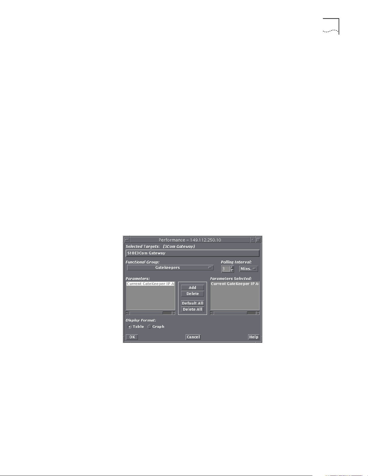
The Performance window appears.
Figure 1 Performance Window
4 Select Gatekeepers from the Functional Group.
5 Select Current Gatekeeper IP address and click Add. Click OK.
A real time table appears and displays the selected Gateway and the
Gatekeeper to which it is registered. The IP address of the Gatekeeper to
which it is registered also appears.
Page 24

24 CHAPTER 1: INSTALLATION
Integrating with HP OpenView
The IP Telephony Manager installation script installs OpenView integration files
to the appropriate OpenView Network Node Manager subdirectories.
OpenView integration occurs as part of the IP Telephony Manager installation,
when the OpenView environmental variables are set beforehand. To integrate
IP Telephony Manager with OpenView manually, follow the procedure below.
1 Set the OpenView environmental variables.
# cd /opt/OV/bin
# . ./ov.envvars.sh
2 Test the environmental variables.
# cd $OV_BIN
# pwd
Solaris responds as follows:
/opt/OV/bin
3 Change to the directory that contains the integration files.
# cd $TCMHOME/ovw
4 Install the integration files.
# ./Install
You can run the $TCMHOME/ovw/Install script at any time. You do not need
to run $TCMHOME/ovw/Remove before running $TCMHOME/ovw/Install
again.
HP OpenView integrates the IP Telephony Manager icons; this lets you access IP
Telephony Manager from HP OpenView.
Fixing Incorrect Maps If you populate CommWorks devices in OpenView before you installed IP
Telephony Manager, IP Telephony Manager integration does not change the
component type from a non-CommWorks type to a CommWorks chassis type.
You cannot do this automatically in HP OpenView. For best results, delete and
rediscover the CommWorks devices.
You can also use the OpenView ovtopofix -r -o <object id> command.
CommWorks object IDs 1.3.6.1.4.1.429.2.1 through 1.3.6.1.4.1.429.2.9 must
each be individually specified.
Page 25

Integrating with HP OpenView 25
If CommWorks devices were populated in OpenView before IP Telephony
Manager was installed, the network map will not display the CommWorks
bitmaps correctly after IP Telephony Manager integration. This occurs even if
the CommWorks menu options are not enabled and the isUSREntNetHub
capability is not set to True. For best results, delete and rediscover the
CommWorks devices.
Removing HP
OpenView Integration
Erasing IP Telephony
Manager
Verifying the
Installation
To remove OpenView integration:
1 Login as root.
2 Type the following:
cd $TCMHOME/ovw
./Remove -r
While all CommWorks files are removed from HP OpenView, no changes are
made to the runtime databases. One of the primary purposes of removal is to
prepare for a new installation.
To erase IP Telephony Manager from HP OpenView, replace the current maps
with new ones. You can also delete and rediscover all the CommWorks devices
from each map.
Start IP Telephony Manager with the following commands:
> TCMHOME=<installation directory>
> export TCMHOME
> PATH=$PATH:$TCMHOME/bin
> export PATH
> ./xtcmvfpd <TCH IP_Address/HostName>
IP Telephony Manager opens.
For a complete description of the menus on the GUI, refer to Chapter 3
Navigating and Using the System
.
Page 26

26 CHAPTER 1: INSTALLATION
Linking CommWorks Objects
If you choose to install HP OpenView, you must install it before IP Telephony
Manager. This lets you start IP Telephony Manager directly from HP OpenView.
To link CommWorks objects in HP OpenView to IP Telephony Manager, use the
following procedure.
1 Typ e:
#cd $OV_BIN
#./ovstart
#./ovw
2 Go to the chassis to be linked, and then click on it.
3 Right click and select Symbol Properties from the pop-up menu.
4 Under Behavior, click Execute.
5 Under Application Action, click USRRobotics: USRVFPD.
6 Click Target Objects, click Add, and then click OK.
7 Click OK on the window that appears.
8 Double-click the object with the chassis IP address.
The chassis graphical user interface appears.
Page 27

2
CONFIGURATION
This chapter describes how to configure CommWorks IP Telephony Manager.
This chapter contains the following topics:
■ Management Station Configuration
■ Component Configuration
■ Synchronizing Network Time
■ Auto Response
■ Setting Authorized Stations
■ Defining a Range of IP Addresses for Authorized Access
■ Threshold Monitoring Configuration
Management Station Configuration
■ Saving and Restoring Configurations
Refer to Chapter 3 for a complete description of the IP Telephony Manager
menus.
Unless otherwise specified, this document uses the generic term edge server to
refer to either the edge server card or the EdgeServer Pro card.
You should not need to configure your management station after installing IP
Telephony Manager for UNIX. IP Telephony Manager adds the following files to
locations as set up in $OV_BIN/ov.envvars.sh:
Tab le 7 Files added to HP OpenView Windows Directories
Category File location
Field definitions $OV_FIELDS/C/usr_fields
Application registration $OV_REGISTRATION/C/USRobotics
CommWorks-specific
symbols
CommWorks icon bitmaps $OV_BITMAPS/C/connector/usr.* (various)
CommWorks MIB $OV_SNMP_MIBS/Vendor/USRobotics/usr-mib
OID-to-symbol mappings appended to $OV_CONF/C/oid_to_sym
$OV_SYMBOLS/C/Connector/USR* (various)
Page 28

28 CHAPTER 2: CONFIGURATION
Component Configuration
The IP Telephony Manager Console window is used to select target
components whenever you are performing configuration, sending commands,
or upgrading components through software download.
Launching the
Configuration Tool
There are two ways to launch the Configuration Tool:
■ From the IP Telephony Manager Console, select a target from the IP
Telephony Manager Console window, and then from the Configuration
menu, select Programmed Settings.
■ From the UNIX command line, type xtcmconf followed by the IP address or
hostname of the target device and the target slots and channels (refer to
Synchronizing Network Time
Appendix B Command Line Interface
You must synchronize the system time of each component in the network
accurate tracking of the IP telephony traffic. To achieve system
for more details).
synchronization, set each Gatekeeper, SIP Proxy Server, and Back-end Server to
Greenwich Mean Time (GMT) and use the Network Time Protocol (NTP) on all
system components.
Setting the Time Zone For each Gatekeeper, SIP Proxy Server, and Back-end Server in the IP telephony
network, set the time zone to GMT.
Recording the NTP IP
Addresses
1 From the Windows desktop, click Start, then Settings, and then click Control
Panel.
2 Double-click Date/Time.
The Date/Time Properties window appears.
3 Click Time Zone.
4 From the drop-down list, select [GMT] Greenwich Mean Time: Dublin,
Edinburgh, Lisbon, London.
5 Click OK.
NTP uses a primary and a secondary NTP time server for system time. You can
use the IP addresses of NTP time servers that are local to your network, or you
can use public NTP time servers. The IP addresses of public NTP time servers are
available on the internet. Use the following procedure to record a primary and
secondary NTP time server address.
Selecting Local NTP Servers
If your local network includes local NTP time servers, record the IP address of
the primary NTP time server and the secondary NTP time server.
Page 29
Synchronizing Network Time 29
Selecting Public NTP Servers
1 From any computer with internet access, access the following website:
http://www.eecis.udel.edu/~mills/ntp/clock1.htm
2 From the website, record the IP addresses for two separate active servers. One
is used as the primary NTP server, and the other is used as the secondary NTP
server. We recommend choosing NTP server locations that are as close to the
Media Gateway chassis as possible.
Setting the NTP
Parameters
Use NTP to synchronize the time across the network. The NTP parameters must
be set for the HiPer NMC card in each Media Gateway chassis, the
Gatekeepers, SIP Proxy Servers, and the Back-end Servers.
All Media Gateway chassis components are automatically synchronized
through the controlling HiPer NMC after it is configured for NTP.
Setting the NTP Parameters for the HiPer NMC
For the HiPer NMC card in each Media Gateway chassis, do the following:
1 Using IP Telephony Manager, open the Media Gateway chassis.
2 Select the HiPer NMC card.
3 Click Configuration, then Programmed Settings from the IP Telephony
Manager Console window.
4 Select Network Time Protocol from the Parameter Group drop-down list.
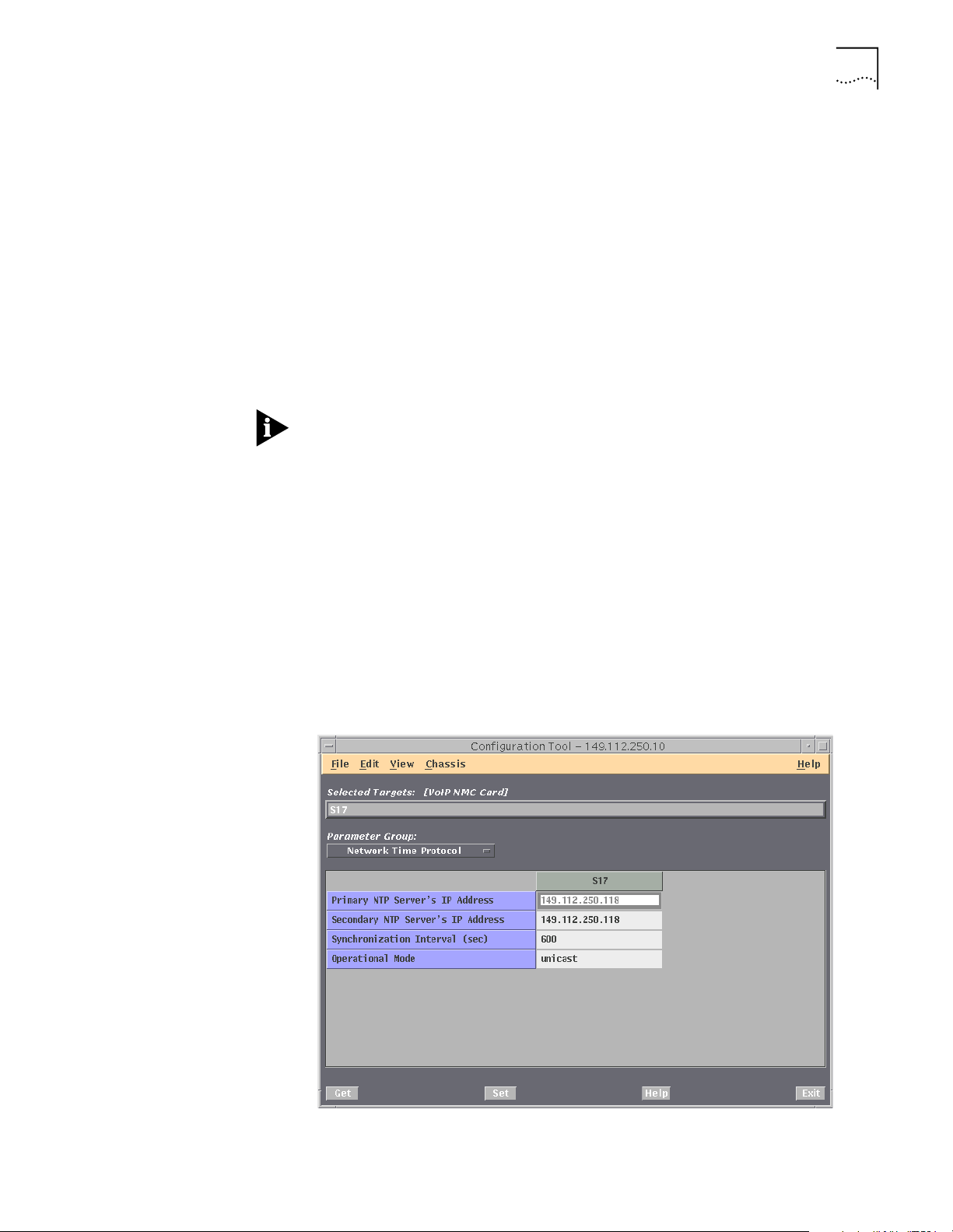
The Network Time Protocol windows appears.
Figure 2 Media Gateway Network Time Protocol Window
Page 30
30 CHAPTER 2: CONFIGURATION
5 Enter the Primary and Secondary NTP IP Addresses (refer to Recording the NTP
IP Addresses).
6 Set the Operational Mode to Unicast.
7 Click Set.
Setting the NTP Parameters for the Other Entities
For each Gatekeeper, SIP Proxy Server, and Back-end Server:
1 Using IP Telephony Manager, open the targeted server.
2 Select the server icon.
3 Select Configuration, then Programmed Settings from the IP Telephony
Manager Console window.
4 Select 3Com SNMP Agent from the Select Entity drop-down list.
5 Click OK.
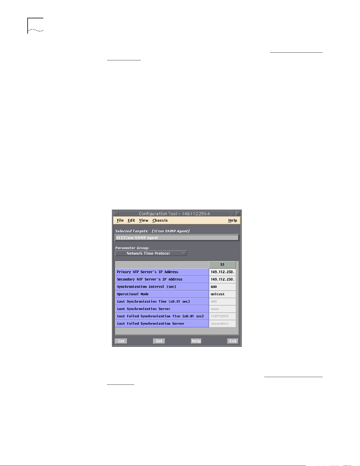
6 Select Network Time Protocol.
A window similar to the following appears:
Figure 3 Server Network Time Protocol Window
7 Enter the Primary and Secondary NT IP addresses (refer to Recording the NTP IP
Addresses).
8 Set the Operational Mode to Unicast.
9 Click Set.
10 Click Exit.
Page 31

Auto Response 31
Auto Response AutoResponse lets network managers define a set of actions (auto response
script) to be taken automatically when a specified event occurs in the chassis.
The event may be specific to a particular module (NAC or NMC) in a given slot
of the chassis, or specific to a particular entity (such as a single modem
channel).
IP Telephony Manager provides a convenient graphical user interface (GUI) for
the Network Manager to configure automatic responses to a specified event. It
is available on the AutoResponse drop-down menu from the Configure menu.
IP Telephony Manager does not need to be running when an event occurs for
the NMC to invoke the appropriate response, because these responses are
programmed into the NMC.
When there are thresholds for an event, they must be programmed through
the Configuration Tool. For example, the Connection Time Limit Expired event
requires that you specify the Connection Time Limit threshold.
AutoResponse
Configuration
To define the automatic responses:
1 Click one or a group of slot(s)/channel(s) on the IP Telephony Manager console
window.
2 On the Main Menu bar, click Configuration, and then click AutoResponse.
■ If you selected the edge server card, click OK on the Select Entity window.
The AutoResponse window appears.
■ If you selected the HiPer DSP card, select where you want the auto response
to be set, either the card or template level and click OK.
■ The AutoResponse window appears.
Figure 4 AutoResponse Window
Page 32

32 CHAPTER 2: CONFIGURATION
3 Select the event from the Event drop-down list.
4 Select what you want the system to do when the selected event occurs from
the Available Responses list and click Add.
The response is added to the Responses Configured list box.
5 Click OK.
The response scripts are loaded.
Responses can only be added one at a time. Some responses may require
additional information (for example, Delay N. Seconds). For responses that
require additional input (a descriptor), the AutoResponse Parameters window
displays.
Setting Authorized Stations
The chassis Network Management Card (NMC) contains an authorized access
list that lets you limit management capability to specific management stations
on your network. After you have created entries in the authorized access list,
only those management stations can send SNMP requests to that device.
To set up an authorized access list:
1 Open a console window for the device whose authorized access list you want
to change.
2 From the Security menu, select Authorized Stations.
The Authorized Stations window appears.
Figure 5 Authorized Stations Window
3 From the Authorized Stations Add window, click Add.
The Authorized Stations Add dialog box appears.
Page 33

Setting Authorized Stations 33
Figure 6 Authorized Stations Add Window
4 In the Add dialog box, enter the IP address for the workstation you are
currently working from and click OK.
The Authorized Stations Completion window appears with the newly added IP
addresses listed.
Figure 7 Authorized Station Completion Window
For information about setting the network mask, refer to Defining a Range of
IP Addresses for Authorized Access later in this chapter.
5 Click Add to add additional entries for other workstations you want to grant
management access.
6 Repeat these steps for each device on your network.
7 If you changed the authorized stations on the Gatekeeper, SIP Proxy Server, or
any of the Back-end Servers, you must restart the SNMP agent. Refer to
Restarting Other Entities
in Chapter 4 for more information.
Page 34

34 CHAPTER 2: CONFIGURATION
Defining a Range of IP Addresses for Authorized Access
Threshold Monitoring Configuration
You can define a range of IP addresses for authorized access by using the
Network Mask field in the authorized access list.
The network mask that you type in this field masks the IP address for that entry
to define a range of authorized IP addresses.
For example, a network mask of 255.255.255.255 prevents access from all IP
addresses except the destination IP address. An entry with a destination IP
address of 139.78.202.192 and a network mask of 255.255.0.0 grants access
to all stations with IP addresses within the range of 139.78.0.0 and
139.78.255.255. An entry with the same IP address and a network mask of
255.0.0.0 grants access to all stations with an IP address beginning with 139.
Threshold monitoring provides local monitoring of any MIB object’s value and
establishes threshold levels for which events can be generated. You can select
which objects to monitor and designate the threshold levels. Threshold values
can be provisioned independently to issue events if the actual values cross the
thresholds. This is different from trap filtering which describes how to
configure the frequency of the traps. This, instead, places thresholds on
certain performance parameter values and issues a trap when the threshold is
exceeded.
To set threshold monitoring from IP Telephony Manager:
1 Open a console window for the device where the threshold is going to be set.
(For the Media Gateway, you need to select the edge server card.)
2 From the Configuration menu, click Programmed Settings.
3 Select the 3COM SNMP SubAgent from the Select Entity window (For
Back-end Servers and the Gatekeeper, select 3Com SNMP Agent.) and click
OK.
Figure 8 Selecting an Entity Window
4 From the Parameter Group Selection window, select Threshold Monitor
Configuration.
Page 35

Threshold Monitoring Configuration 35
Figure 9 Parameter Group Selection Window
The Threshold Monitor Configuration window appears.
Figure 10 Configuring Thresholds Window
Page 36

36 CHAPTER 2: CONFIGURATION
The following table contains the fields and the values of the Configuring
Threshold window.
Tab le 8
Field Name Description Possible Selections
Threshold Object Object ID which is to be monitored.
Threshold Alias Alias for the object ID. This is used
Threshold Period Frequency at which this parameter
Threshold Type Type of the collection. None
Threshold Alarm Value Threshold, which if crossed, results
Threshold Alarm Clear
Value
Threshold Monitor Configuration Fields
This has 4294967294 at the end if
an object with multiple instances is
to be monitored.
to differentiate the different objects
being monitored. The alias is sent in
the threshold trap for identifying
the monitor object that has crossed
the threshold or cleared the
threshold
is monitored.
in a trap
Threshold, which if crossed in the
reverse direction, results in a
threshold clear trap
Example:
1.3.6.1.4.1.429.4.75.5.1.8.0
The alias has to be unique
across all objects to be
monitored.
0 sec
15 sec
30 sec
1 minute
15 minutes
30 Minute
Delta: The difference between
the start and the end of the
period is used.
Absolute: The actual value is
used
An integer value.
If you set the Threshold Type to
Absolute, a trap is sent when
the current value is greater
than the integer value you
entered.
If you set the Threshold Type to
Delta, a trap is sent when the
delta of the threshold period is
greater than the integer value
you entered.
An integer value.
If you set the Threshold Type to
Absolute, a clear trap is sent
when the current value is less
than the integer value you
entered.
If you set the Threshold Type to
Delta, a clear trap is sent when
the delta of the threshold
period is less than the integer
value you entered.
Page 37

Adding a Threshold Parameter 37
Tab le 8 Threshold Monitor Configuration Fields (continued)
Field Name Description Possible Selections
Threshold Event
Severity
Threshold Alarm State State of the threshold object. If an
Threshold Row Status Status of the threshold object. This
The severity configured will be sent
in the trap.
object is not active, then it has a
state of none. If an object is above
threshold, then this object will show
that state. If an Object has cleared
the threshold, then it will show that
state. If an object is not a part of
the CommonAgent, the
thresholdState will become invalid.
If an object is not internally
accessible, then it will have a state
of Inaccessible.
This is a read-only column.
is a user-defined entry that is used
to create rows in the table. The
state rowstate can itself be only
active, notReady, notInService. A
rowState of notReady implies that
one or more parameters of the row
haven’t been set to the correct
value. A row in the underCreation
state can be set to active state.
None
Critical
Warning
Informational
None
Invalid
Warning
Critical
Clear
Inaccessible
Information
Active
CreateAndWait
notInService
destroy
notReady
createAndGo
Adding a Threshold Parameter
5 After you have set the trap thresholds on the Gatekeeper, SIP Proxy Server, or
any of the Back-end Servers, you must restart the SNMP agent. Refer to
Restarting Other Entities
in Chapter 4 for more information.
To add a parameter to monitor:
1 Open a console window for the device where the threshold parameter is going
to be added. (For the Media Gateway, you need to select the edge server card.)
2 From the Configuration menu, click Programmed Settings.
3 Select the 3COM SNMP SubAgent from the Select Entity window (For
Back-end Servers and the Gatekeeper, select 3Com SNMP Agent.) and click
OK.
Page 38

38 CHAPTER 2: CONFIGURATION
Figure 11 Selecting an Entity Window
4 From the Parameter Group Selection window, select Threshold Monitor
Configuration.
Figure 12 Parameter Group Selection Window
The Threshold Monitor Configuration window appears.
Page 39

Figure 13 Configuring Thresholds Window
Adding a Threshold Parameter 39
5 Configure the fields in the Configuring Threshold window as needed. Refer to
Tab le 8
. Click Set.
6 Set Threshold Row Status to createAndGo. As shown in the following
figure.
Page 40

40 CHAPTER 2: CONFIGURATION
Figure 14 Adding Threshold Parameters Window
Editing a Threshold Parameter
7 Click Set.
8 If you changed the threshold parameters on the Gatekeeper, SIP Proxy Server,
or any of the Back-end Servers, you must restart the SNMP agent. Refer to
Restarting Other Entities
To edit a parameter that is being monitored:
1 Open a console window for the device where the threshold is going to be
edited. (For the Media Gateway, you need to select the edge server card.)
2 From the Configuration menu, click Programmed Settings.
3 Select the 3COM SNMP SubAgent from the Select Entity window (For
Back-end Servers and the Gatekeeper, select 3Com SNMP Agent.) and click
OK.
Figure 15 Selecting an Entity Window
in Chapter 4 for more information.
Page 41

Editing a Threshold Parameter 41
4 From the Parameter Group Selection window, select Threshold Monitor
Configuration.
Figure 16 Parameter Group Selection Window
The Threshold Monitor Configuration window appears.
Figure 17 Configuring Thresholds Window
Page 42

42 CHAPTER 2: CONFIGURATION
5 Set Threshold Row Status to notinsservice.
6 Change the configuration as you need, refer to Table 8
, and click Set.
7 Set the Threshold Row Status to active.
The following figure shows the Threshold Parameter drop-down list.
Figure 18 Editing Threshold Parameters Window
8 Click Set.
9 If you changed the threshold parameters on the Gatekeeper, SIP Proxy Server,
or any of the Back-end Servers, you must restart the SNMP agent. Refer to
Restarting Other Entities
in Chapter 4 for more information.
Threshold Traps IP Telephony Manager issues the following traps depending on the Threshold
event severity configured:
■ Threshold Warning
■ Threshold Critical
■ Threshold Informational
■ Threshold Warning Clear
■ Threshold Critical Clear
■ Threshold Informational Clear
Page 43

Saving and Restoring Configurations 43
Saving and Restoring Configurations
The Save configuration utility performs a discovery of the configuration of a
device and saves it to a file. After it is saved to a file, the Restore configuration
utility is used to restore the configuration to that device, or it can be used to
apply the file to other devices with similar components.
You can initiate a device save or restore in any of the following ways:
■ From the File menu of the IP Telephony Manager Console
■ From your network management platform (HP OpenView). For information
on how to save and restore a device from your network management
platform, refer to your network management User Guide.
■ From the UNIX command line. For information on saving and restoring
operations from the command line, refer to Appendix B, Command Line
Interface
There are four ways to save configurations:
■ Saving a Chassis Configuration to NVRAM—The Media Gateway
configuration can be saved to a file on the network.
■ Component Save to NVRAM—Most components contain their own
nonvolatile read access memory (NVRAM). The Media Gateway’s current
configuration can be saved to its NVRAM and later retrieved through a
direct command or by resetting the component.
Saving a Chassis
Configuration to
NVRAM
■ NMC Save Chassis to NVRAM—An entire device’s configuration can be
saved to the NMC NVRAM.
■ Saving Chassis Configurations from CFM—This feature lets you save the
configurations of every component of a device to a file (for example, the
configuration of all the cards and channels in a chassis, and the servers).
There are two ways to restore the configurations:
■ Restoring a Chassis Configuration from NVRAM—An entire device's
configuration can be restored from a file on the network.
■ Restoring Chassis Configurations from CFM—This feature lets you
restore the configurations of every component of a device from a file (for
example, the configuration of all the cards and channels in a chassis and
the servers). The device configuration can be restored to that device, or
applied to other devices with similar components.
Use the following procedure to save a Media Gateway chassis configuration to
NVRAM using the IP Telephony Manager.
1 From the IP Telephony Manager Console window, select File menu, and click
Save Chassis NVRAM.
The Save Chassis NVRAM dialog box appears.
Page 44

44 CHAPTER 2: CONFIGURATION
Figure 19 Save Chassis NVRAM Dialog Box
Restoring a Chassis
Configuration from
NVRAM
2 Enter or select the .nvr file you are saving to and click OK.
The default directory for .nvr files is: $TCMHOME/data/nvram/.
If you are saving or restoring from the command line and you are not using the
x prefix option, progress is reported as status messages on screen. For more
information, refer to Appendix B, Command Line Interface.
The Chassis Save Progress window appears.
3 When the save is completed, click OK.
To restore a Media Gateway chassis configuration from NVRAM using IP
Telephony Manager:
1 From the IP Telephony Manager Console window, select File menu, and click
Restore Chassis NVRAM.
The Restore Chassis NVRAM dialog box appears.
Page 45

Saving and Restoring Configurations 45
Figure 20 Restore Chassis NVRAM Dialog Box
Component Save to
NVRAM
2 Enter or select the .whb file you are restoring from and click OK.
The default directory for .nvr files is: $TCMHOME/data/nvram/.
If you are saving or restoring from the command line and you are not using the
x prefix option, progress is reported as status messages on screen. For more
information refer to Appendix B, Command Line Interface.
The Chassis Restore Progress window appears.
3 When the restore is completed click OK.
Some device components, such as modems, store their settings in their own
NVRAM and use them for power-on and reset defaults.
To save a component’s settings to NVRAM:
1 Select the component whose configuration you are saving on the IP Telephony
Manager console display.
2 Select Configuration from the IP Telephony Manager Console window.
3 Select Action/Commands from the drop-down menu.
4 Click the Card Level radio button.
5 Select Software in the Category box.
6 Select Both T1/E1 and Modem to NVRAM in the Command to Execute box.
To load a component’s NVRAM settings, issue the Restore from NVRAM
command from the same command group as the Save to NVRAM command.
Page 46

46 CHAPTER 2: CONFIGURATION
Not all components support the Save to NVRAM feature. For those that
support this feature, the HIPer DSP and NMC cards, you must select the right
command type and group. For example, the modem software command
group is available only when you select modems at the channel level, as
opposed to selecting the whole card. For T1 cards, you must select the whole
card and choose the software command group. Refer to Appendix C for a list
of available commands for each type of IP Telephony Manager component.
NMC Save Chassis to
NVRAM
Saving Configurations
to the CFM
Use the Save Chassis to NVRAM command to save the configuration of each
component in a device to the NMC’s NVRAM. You can then restore this
configuration to that device by using the Restore Chassis from NVRAM
command.
To execute the Save Chassis to NVRAM and Restore Chassis from NVRAM
commands, follow this procedure:
1 Select the NMC card (or management module) from the IP Telephony Manager
console window.
2 Select Actions/Commands from the Configuration menu.
The Command window appears.
3 Select Save Chassis from NVRAM or Restore Chassis from NVRAM from
the Command to Execute drop-down box.
4 Click Execute, and wait for the Success result.
Use the following procedure to save the configuration of the Media Gateway
chassis, Gatekeeper, SIP Proxy Server, or Back-end Server to the Configuration
File Manager (CFM) using the IP Telephony Manager.
1 From the IP Telephony Manager Console window, select File menu, and click
Save CFM.
The Save CFM dialog box appears.
2 When the save is completed, click OK.
Page 47

Saving and Restoring Configurations 47
Figure 21 Save Chassis CFM Dialog Box
3 Enter or select the .cfm file you are saving to and click OK.
Restoring a
Configuration from
CFM
The default directory for .nvr files is: $TCMHOME/data/nvram/.
If you are saving or restoring from the command line and you are not using the
x prefix option, progress is reported as status messages on screen. For more
information refer, to Appendix B, Command Line Interface.
The Chassis Save Progress window appears.
4 When the save is completed, click OK.
Use the following procedure to restore the configuration of the Media
Gateway chassis, Gatekeeper, SIP Proxy Server, or Back-end Server to the
Configuration File Manager (CFM) using the IP Telephony Manager.
1 From the IP Telephony Manager Console window, select File menu, and click
Restore CFM.
The Restore CFM dialog box appears.
Page 48

48 CHAPTER 2: CONFIGURATION
Figure 22 Restore Chassis CFM Dialog Box
2 Enter or select the .cfm file you are restoring from and click OK.
The default directory for .cfm files is: opt/tcm/data/cfm/tch.
If you are saving or restoring from the command line and you are not using the
x prefix option, progress is reported as status messages on screen. For more
information, refer to Appendix B, Command Line Interface.
The Chassis Restore Progress window appears.
3 When the save is completed, click OK.
4 Restart the SIP Proxy server to ensure that the Back-end server addresses from
the restore are used. Refer to the CommWorks 4220 SIP Proxy Server Guide for
more information on restarting the SIP Proxy server.
Page 49

3
NAVIGATING AND USING THE SYSTEM
This chapter describes the menus in the IP Telephony Manager. The function of
the menus can vary depending on the component, if that is the case, then you
are referred to that individual component’s user manual.
This chapter contains the following topics:
■ Accessing IP Telephony Manager Window
■ File Menu
■ View Menu
■ Configuration Menu
■ Fault Menu
■ Performance Menu
Accessing IP Telephony Manager Window
■ Security Menu
As an example, the descriptions in this section pertain to the CommWorks IP
Telephony Media Gateway. The server menus are similar to the windows
described here.
There are two main menus in the IP Telephony Manager. One is for the Media
Gateway chassis and the other one is for the Back-end Server(s), Gatekeeper,
or SIP Proxy Server.
To access the either main menu, from the command line prompt, type one of
these commands:
# xtcmvfpd
or
# xtcmvfpd <target chassis IP address>
The first command lists the chassis components. You then select the
component that you want to start. The second command, you specify the IP
address of the component that you want to start.
If the Media Gateway was specified:
The IP Telephony Manager Console window appears.
Page 50

50 CHAPTER 3: NAVIGATING AND USING THE SYSTEM
Figure 23 IP Telephony Manager Console Window
The IP Telephony Manager Console window contains a graphical
representation of the Total Control chassis. The view can be changed by the
View menu to see the front or back of the chassis. Select the area of the
chassis on the IP Telephony Manager Console window on which you want the
function to be performed, then select the function from the main menu bar.
In general:
■ Click on LEDs to select individual channels or entities, or the area just
outside the LEDs to select the whole card. For Network Interface Cards
(NICs), click the connectors.
■ The card’s identity appears to the left of the IP Telephony Manager Console
window.
■ To select more than one channel or entity at a time, hold down the Shift
key.
■ You can select only one type of card at a time (for example, you can select
two HiPer DSP Modem cards, but not a HiPer DSP card and some other type
of modem card).
■ To select all the same type of channels or components in a card, use the All
Like Devices setting in the Select drop-down box at the upper right corner
of the IP Telephony Manager Console window.
If a Gatekeeper, SIP Proxy Server, or a Back-end Server was selected:
The IP Telephony Manager Server window appears.
Page 51

Accessing IP Telephony Manager Window 51
Figure 24 IP Telephony Manager Server Window
To perform a function on the Gatekeeper, SIP Proxy Server, or Back-end Server,
click on the server icon and simply choose the command from the main menu.
The remainder of this section describes the functions located on the main
menu.
As you can see, the Chassis Console window and the Server windows contain
the same menu items. For ease of reference, the IP Telephony Manager
Console windows are used as examples. It is noted when a drop-down
submenu is for the IP Telephony Manager Chassis Console only.
Page 52

52 CHAPTER 3: NAVIGATING AND USING THE SYSTEM
File Menu The file menu is used to open devices on the system, save and restore
configurations, and to import Software download files.
Figure 25 shows an example of the File menu from the Media Gateway.
Figure 25 File Menu
Open Submenu The Open submenu displays the Device List window. It lets you to access other
devices on your VoIP system.
Figure 26 Device List Window
Chassis Save All
Submenu
The Chassis Save All submenu saves to entire chassis’ configuration to NVRAM
(IP Telephony Manager Chassis Console only).
Page 53

File Menu 53
Save Chassis NVRAM
Submenu
The Save Chassis NVRAM submenu saves the Media Gateway chassis
configuration to a specific file on NVRAM. Refer to Chapter 2 for more
information on saving the chassis to NVRAM (IP Telephony Manager Chassis
Console only).
Restore Chassis NVRAM
Submenu
The Restore Chassis NVRAM submenu restores the Media Gateway chassis
configuration from a specified file. You can also use this submenu to configure
another chassis by using the configuration saved on this file. Refer to Chapter
2 for more information about restoring the Media Gateway chassis
configuration (IP Telephony Manager Chassis Console only).
Save CFM Submenu The Save CFM Submenu saves the chassis or server configuration to a specified
Configuration File Management (CFM) file. Refer to Chapter 2 for more
information about saving the Media Gateway chassis or the server from a CFM
file.
Restore CFM Submenu The Restore CFM submenu restores the chassis or server configuration by using
a specified CFM file. Refer to Chapter 2 for more information on restoring the
Media Gateway chassis or the server from a CFM file.
Import SDL Files
Submenu
The Import SDL Files submenu copies the Software Download (SDL) files to a
specified directory. Refer to Chapter 4 for more information on upgrading your
system using the Software Download menu (IP Telephony Manager Chassis
Console only).
Figure 27 Software Download Window
Exit Submenu The Exit submenu closes the current IP Telephony Manager session.
Page 54

54 CHAPTER 3: NAVIGATING AND USING THE SYSTEM
View Menu The View menu lets you adjust the way IP Telephony Manager displays the
console or server window.
Figure 28 View Menu
Other Side Submenu The Other Side submenu displays the reverse side of the chassis. This guide
shows the front panel of the chassis. Figure 28 shows the back of the Media
Gateway chassis (IP Telephony Manager Chassis Console only).
LED Poll Info Submenu The LED Poll Info submenu displays the status of the LED lights.
Figure 29 LED Poll Info Window
Show Toolbar Submenu The Show Toolbar submenu displays four icons.
Page 55

Figure 30 Icon View Window
View Menu 55
The first icon displays the Command Tool dialog box for the chosen entity.
The second icon displays the Configuration menus.
The third icon displays the software download dialog box for the selected
entity.
The forth icon displays diagnostics information for the selected entity.
Page 56

56 CHAPTER 3: NAVIGATING AND USING THE SYSTEM
Configuration Menu The Configuration menu is used to set the VoIP chassis to your environment
requirements.
Figure 31 Configuration Menu
Programmed Settings
Submenu
The Programmed Settings submenu displays the Configuration Tool window
for the selected entity. Parameters for a given component may be divided into
several groups. When you select the Configuration Tool, the Parameter Group
drop-down box appears, prompting you to select a parameter group. You
must select a group from the Parameter Group drop-down box to continue.
Figure 32 shows an example of the CommWorks EdgeServer Pro card
Parameter Group.
Page 57

Configuration Menu 57
Figure 32 EdgeServer Pro Card Parameter Group Window
The Configuration Tool menu contains the following fields:
■ Selected targets—The name of the target to be configured from this
menu that was selected from the IP Telephony Manager chassis or server.
Displays the slot and channel numbers of the selected components. For
example, S4C1-30 means that channels 1-30 of the component in slot 4 of
a device has been selected. This field is read only.
■ Card-Level and Channel-Level Parameter Groups—IP Telephony
Manager components have different parameter groups depending on
whether you have selected the whole component or individual channels
within a component.
After selecting a parameter group, the configuration table appears, and lists
the current settings for each selected component.
Refer to the individual components user guides for information on configuring
these parameter groups.
Column headings display slot and channel numbers for each selected
component.
Page 58

58 CHAPTER 3: NAVIGATING AND USING THE SYSTEM
Figure 33 Example of HiPer DSP Modem Identification Configuration Table
Click on the cell with the setting you want to edit. If a value is read-only, the
cursor changes to the “No” sign when placed over the cell.
If the value can be modified, an arrow appears in the value field. When you
click on the field, a drop-down box appears, listing the possible values for the
configuration. You can also use the Tab key to navigate through the fields.
After a value has changed in the configuration table, it turns blue (default).
The new value is not changed in the component, until you click Set. After a Set
is issued and the value is changed in the component, the color returns to
normal.
Other fields on the Configuration Tool menu are:
■ Window Title Bar—Displays the target device IP address.
■ Get Button—Triggers the SNMP Get operation for the selected parameter
group. The Get operation updates the display with the last-saved values.
■ Set Button—Triggers the SNMP Set operation for the selected parameter
group. The Set operation writes the displayed values to the device MIB.
■ Help—Displays information about configurable parameters. Click on the
Help button. The context-sensitive help icon appears. Simply click the
parameter/object for which you want additional information. The system
launches your HTML browser.
Page 59

Configuration Menu 59
■ Exit—Closes the window and displays the previous window.
■ Adjusting Column Width—You can adjust the column width using the
mouse. Place the cursor over the column divisor line until it changes to a
bar and arrow, then click and drag the line left or right.
Action/Commands
Submenu
The Action/Commands submenu displays the Command Tool window for the
selected entity.
Figure 34 shows an example of the CommWorks EdgeServer Pro entity.
Figure 34 Command Tool Window
The Command Tool window contains the following fields and control buttons:
■ Selected Targets—Displays the card type, the slots, and channels that
receives the command.
■ Category—Some cards have different command categories. If the selected
targets have only one command category, this box is grayed out.
■ Command to Execute—Click this box to select the command you want to
execute for the selected targets.
■ Force Command—The card may be in a state where the selected
command is normally rejected (for example, a modem in dial mode). Check
this box to override this lockout.
■ Command Specific Parameter—Commands for some device types
require an additional parameter to be specified when the command is
issued. his parameter is not required for the Total Control chassis.
■ Issued—Indicates whether or not the command was successfully initiated.
■ Result—Indicates the results of the last executed command.
■ Comment—Displays details about failed commands.
Page 60

60 CHAPTER 3: NAVIGATING AND USING THE SYSTEM
■ Execute—Executes the selected command for the selected targets.
■ Close—Closes the Command Tool window.
Software Download
Submenu
The Software Download submenu displays the files to be downloaded for the
specified entity. You then select the files you need to be downloaded. Refer to
Chapter 4 for more information.
Inventory Submenu The Inventory submenu displays the inventory information for each
component on the selected chassis (IP Telephony Manager Chassis Console
only).
Figure 35 Inventory Window
The Inventory window contains the following fields:
■ Slot #—Each entry in the inventory data table is labeled by its slot number
in the chassis.
■ Description—Textual description of the displayed chassis.
■ Serial Number—Serial number of the component.
■ Product Code—Hardware product code of the component.
■ Hardware version—Hardware version of the component.
■ DRAM (KB)—Amount of dynamic RAM installed in the component.
■ Flash RAM—Amount of flash RAM installed in the component.
■ DIP Switches—A bit field value displaying DIP switch settings currently in
effect.
Graphically, the displayed binary corresponds to settings as follows:
DIP Switch Numbers: 16151413121110987654321
Bit Field Placeholders: 0000000000000000
Where a "1" at any of the above positions means that the corresponding
DIP switch is ON.
Page 61

Configuration Menu 61
For example, 0000000010010000 means that DIP switches 8 and 5 are ON
and all others are off.
■ Software Version—Version of software currently installed in the
component's flash RAM.
You can perform the following tasks from this window:
■ Save—Saves the inventory data table to an ASCII text file.
■ Exit—Closes the inventory utility.
■ Print—Prints displayed data to a printer or file either in postscript or ASCII
format. Figure 36 shows the Inventory Print menu.
Figure 36 Inventory Print Menu
AutoResponse
Submenu
The Inventory Print menu contains the following selections:
■ Print Target—Selects whether to print to file or print to a printer.
■ Print Format—Selects whether to print in postscript format or ASCII text
format.
■ Print Command—Postscript output is piped to this command. The
TCM_PRINT_COMMAND system parameter sets the default.
The AutoResponse submenu lets you define what messages need to appear
when an event occurs. Refer to Chapter 2 for more information on how to set
the auto response messages (IP Telephony Manager Chassis Console only).
Page 62

62 CHAPTER 3: NAVIGATING AND USING THE SYSTEM
Figure 37 Auto Response Window
The AutoResponse dialog box contains the following fields and buttons:
■ Selected Targets—This box shows the slot(s) or channel(s) selected in the
chassis display.
■ Event—Click this box to select an event. If you select an event that requires
a descriptor, make sure that you have programmed the descriptor.
■ Response Script Usage %—This indicator shows the percentage of
available script space you have programmed. Each response may take up a
different amount of script space. Monitor this gauge to avoid programming
too many responses to a single event.
■ Available Responses/Response Script—The responses available for the
event appear on the left, and the responses configured for the event appear
on the right. Refer to AutoResponse Editing for information about
configuring the list. When you select a response that has descriptors, a
window of descriptor options appears .
■ Add—Assigns the selected response to an event.
■ Delete—Removes the selected response.
■ Delete All—Removes all the selected responses from the Responses
Configured list.
■ Get—Queries the NMC for the response script associated with the event.
■ Set—Assigns the selected response script to the event.
■ Load From—Displays the Load From Device window.
Page 63

Fault Menu 63
Fault Menu The Fault menu lets you enable/disable traps and define the trap’s destination.
Figure 38 Fault Menu
Trap Settings Submenu The Trap Setting submenu defines the traps for the specified entity. Refer to
the individual component user guide for information about setting this for
your VoIP component.
Figure 39 Trap Setting Window
Page 64

64 CHAPTER 3: NAVIGATING AND USING THE SYSTEM
Trap Destination
Submenu
The Trap Destination submenu defines and modifies where the traps are sent.
Refer to the individual component user guide for information about setting
this for your VoIP component.
Figure 40 Trap Destination Window
Performance Menu The Performance menu lets you define the events on your system that IP
Telephony Manager is to monitor.
Performance Monitor
Submenu
Figure 41 Performance Window
The Performance submenu lets you define the events that you want IP
Telephony Manager to monitor and it then report on those events. You can
also view historical information. Refer to the individual component user guide
for information about setting this for your VoIP component.
Page 65

Security Menu 65
Figure 42 Performance Monitor Menu
After you click OK, a table, or graph appears showing the events you selected
in real time mode.
Security Menu The Security menus lets you set the SNMP community strings and maintain the
management capabilities at the selected station.
Figure 43 Security Menu
Page 66

66 CHAPTER 3: NAVIGATING AND USING THE SYSTEM
Community Names
Submenu
Authorized Stations
Submenu
The Community Names submenu lets you set the SNMP community strings.
The IP Telephony Manager default value for SNMP community string is public
for read only and private for read-write. To change the default values, you
must first change the community string on the devices and then on IP
Telephony Manager.
For security reasons, you cannot view the community strings through IP
Telephony Manager.
For information about changing the community strings, refer to Changing the
SNMP Community Strings, in Chapter 4.
The Authorized Stations submenu lets you maintain the management and
security functions for the specified station.
The chassis Network Management Card (NMC) contains an authorized access
list that lets you limit management capability to certain management stations
on your network. After you create entries in the authorized access list, only
those management stations can send SNMP requests to that device.
For information about setting the authorizations for a station, refer to Setting
Authorized Stations, in Chapter 2.
To set up an authorized access list:
1 Open a console window for the device whose authorized access list you want
to change.
2 From the Security menu, select Authorized Stations.
The Authorized Stations window appears.
Figure 44 Authorized Stations Window
The Authorized Station window contains the following buttons:
■ Add—Brings up a dialog box for entry of new authorized stations.
Page 67

Security Menu 67
■ Modify— Brings up a dialog box for changing the network mask or
comment for the selected device. (You must select an entry from the list
before using this button.)
■ Delete—Deletes the selected entry.
When you click Add, the Authorized Stations Add dialog box appears.
Figure 45 Authorized Stations Add Window
The Authorized Stations Add window contains the following fields:
■ Destination IP—Displays the IP address of the authorized station.
■ Network Mask—Displays the network mask for the destination IP address
that defines a range of IP addresses for authorized stations.
■ Comment—Displays a user-entered description of the station.
Page 68

Page 69

4
MAINTENANCE
This chapter describes how to use IP Telephony Manager to upgrade software
and perform general maintenance tasks on CommWorks IP Telephony
Platform cards.
This chapter contains the following topics:
■ Upgrading Software
■ Command Tool
■ Restarting Other Entities
■ Setting Manual Switchovers
■ Changing the SNMP Community Strings
■ Clearing Authorized Access Lists
■ Displaying Inventory Information
Unless otherwise specified, this document uses the generic term edge server to
refer to either the edge server card or the EdgeServer Pro card.
Upgrading Software You can upgrade the Media Gateway, Gatekeeper, SIP Proxy, and Back-end
Server software using SDL-2. IP Telephony Manager uses SDL-2 functionality to
perform upgrades through SNMP and TFTP using a file structure of .dmf.
You can upgrade the software for the following entities using SDL-2:
Media Gateway:
■ CommWorks SNMP SubAgent
■ OOBMAN
■ HiPer DSP
■ Network Management Card (NMC)
Signalling Servers:
■ CommWorks SNMP SubAgent
■ Gatekeeper
■ SIP Proxy
■ OOBMAN
Page 70

70 CHAPTER 4: MAINTENANCE
Back-end Servers:
■ CommWorks SNMP SubAgent
■ OOBMan
■ Provisioning Server
■ Directory Mapping Server
■ Accounting Server
■ Billing Support Server
Remote upgrades of the above listed firmware cards are also accomplished
through the use of SDL-2. SMS is no longer used for this purpose.
Software Upgrade
Methods
You can transfer and install upgrade files by any of the following methods:
■ CommWorks IP Telephony Manager—IP Telephony Manager is an
SNMP-based management program for the CommWorks platform. IP
Telephony Manager provides tools to transfer files to one or more
components simultaneously over an IP network.
■ Direct Serial Connection—You can connect a serial cable, with null
modem adapter, between a computer and a serial port on a Total Control
NIC, then transfer a file using any serial communications program that
supports ZMODEM file transfers. Refer to the Total Control 1000 Media
Gateway Guide for more information.
■ SNMP MIB Browser and TFTP Server—If the other two options are not
available, you can use an SNMP MIB browser and an TFTP Server to upgrade
the firmware over an IP network.
■ SDL2 Utility—The SDL2 utility runs on Windows NT. You can use it to
upgrade the Media Gateway, SIP Proxy Server, Gatekeeper, and Back-end
Servers as follows:
1 Connect a console, keyboard, and mouse to the server whose software you
want to upgrade.
2 From the console window, open the command line interface.
3 Enter:
Sdl2 [-hsv] <DMF filename>
The command line options are:
■ -h Help
■ -v Verbose (Error Messages and installation status appear on the command
line.)
■ -s Silent Mode (The setup process does not interact with the user. This is
used on headless stations.)
The SDL2 utility:
■ Creates a temporary directory.
Page 71

Upgrading Software 71
■ Extracts the CAB file from the DMF file.
■ Extracts the installation files from the CAB file.
■ Runs the setup.
Table 9 lists a comparison of the installation methods.
Tab le 9 Upgrade Option Comparison
Option Advantages Disadvantages
IP Telephony Manager
Serial Connection
MIB Browser / TFTP Server
■ Includes all necessary tools
■ Can perform remotely
■ Can upgrade more than one
card at a time
■ Minimal software requirement
(ordinary serial
communications program)
■ Can perform remotely ■ Requires specialized
■ Must install IP Telephony
Manager first
■ Requires a local connection
between NIC and computer
■ Requires an unusual cable
■ Can upgrade only one card
at a time
software
■ Unfriendly user interface
Upgrading the
Software
After you have decided what method you want to install the upgrades, you are
ready to upgrade your system with the current software.
If you need to reload the same version of the software on the Back-end
Servers, you must uninstall the Back-end Server software first.
As an example, the procedures in this section refer to the CommWorks IP
Telephony Media Gateway, specifically the HiPer DSP and HiPer NMC cards.
The software is released as two ZIP files, one for the HiPer DSP and one for the
HiPer NMC.
1 Extract the DMF files using the UNIX unzip command.
The following table lists the contents of the zip file:
Table 10 Zip File Contents
Card ZIP file Contents of ZIP file Contents of EXE file
HiPer DSP hdm02xxxx.zip hd02xxxx.dmf
hr02xxxx.dmf
HiPer NMC nmcdisk3.zip hipernmc.exe hm0704xx.dmf
nmcmibs.exe several MIB files
n/a
2 Copy the DMF files to the /opt/tcm/data/sdl directory.
Page 72

72 CHAPTER 4: MAINTENANCE
If you do not have unzip capabilities on your UNIX system, you can download
the freeware from the internet and install it on your system.
3 Select the component to which you want to download software. The Media
Gateway, Gatekeeper, SIP Proxy Server or select the Back-end Server.
4 If you selected a server to download to, you are prompted to select an entity.
5 From the Configuration menu, click Software Download.
IP Telephony Manager associates the files with the correct component.
Figure 46 Software Download Dialog Box
6 Click Browse.
A new window appears showing all the software files.
Figure 47 Software Download (Select a File) Window
7 Click the software version you want to send to the selected component and
click OK.
This closes the window and brings you back to the Software Download
window.
8 Click OK to start the software download.
Page 73

Command Tool 73
When the software download is complete, a green box appears under the
command status.
9 Click OK when finished.
Command Tool The Command Tool is used to perform hardware and software commands on a
selected component, such as busy-out, disconnect, reset, or save to NVRAM.
As an example, the procedures in this section refer to the CommWorks IP
Telephony Media Gateway.
Launching the
Command Tool
Card-Level vs.
Channel-Level
Commands
To launch the Command Tool, from the IP Telephony Manager Console
window:
1 Select a card from the IP Telephony Manager Console window.
2 Select Actions/Commands from the Configuration menu on the IP
Telephony Manager Console window.
3 Select the entity the command will be performed for.
You can also launch the Command Tool from:
■ The network management platform network map (either OVW Network
Node Manager or SNM): highlight the icon for a IP Telephony Manager
Console device, then select Actions/Commands from the Configuration
menu.
■ The UNIX command line: use the xtcmcmd command, specifying the target
device IP address or hostname and the target slots and channels. For
complete syntax for the tcmcmd command, see Appendix B, Command
Line Interface.
For the Media Gateway chassis, there are different command options
depending on whether you select the whole card or individual channels within
a card. See Appendix C for a list of commands for each type of card.
Command Window After launching the Command Tool, the Command window appears.
Figure 48 shows the hardware commands that can be executed for the HiPer
DSP card.
Page 74

74 CHAPTER 4: MAINTENANCE
Figure 48 Example HiPer DSP Hardware Commands
Figure 49 shows the software commands that can be executed for the HiPer
DSP card.
Figure 49 Example HiPer DSP Software Commands
1 Select the type of command you want to perform from the Command to
Execute or Category drop-down boxes.
2 Click Execute at the bottom of the window.
3 After executing the command, compare the results with the color-coded key
below the status box.
Page 75

Restarting Other Entities 75
Figure 50 Example Media Gateway Command Status Color Codes
Restarting Other Entities
You can restart the Gatekeepers, Back-end Servers, and SIP Proxy Servers
gracefully or by a hard restart. A graceful restart closes all open applications on
the server, closes the operating system, and then restarts the computer, just as
if you restarted the computer from the Windows Start menu. A hard restart
closes the applications, processes, and operating system all at once, just as if
you removed power from the computer. We DO NOT recommend executing a
hard restart.
To restart the Gatekeeper, Back-end Servers, and SIP Proxy Server:
1 Using IP Telephony Manager, open the Media Gateway chassis.
2 Click File, and then click Open.
3 Select the entity you are configuring from the Device List.
4 Click OK.
5 Select the entity icon.
6 From the IP Telephony Manager Console window, select Configuration, then
Actions/Commands.
7 When prompted to select an entity, click Windows NT/OS in the list box, and
then click OK.
8 From the Command to execute menu, select Graceful restart
(recommended) or Hard restart.
9 Click Execute and wait for a successful completion of the command.
10 Click Close.
IP Telephony Manager displays the entity as yellow until the operation
completes. After the restart process is complete, the entity icon appears
normal.
Page 76

76 CHAPTER 4: MAINTENANCE
The entity has been successfully restarted.
Restarting after
Parameter Changes
There are various parameters located under the Configuration menu that can
be set to meet your requirements. The parameters that are prefixed with an
asterisks (*) require that the entity be restarted when changes are made to the
parameter.
The following figure displays some of the parameters with the asterisks (*).
Figure 51 Asterisks Parameter Example
If changes are made to any parameter with an asterisk, the entity selected will
need to be restarted for the new values to be recognized.
If you need to restart the Gateway, you need to restart the edge server Plugin
Manager Service (EPMS). To restart the EPMS, you can either restart the 3Com
Gateway on IP Telephony Manager or stop and start the EPMS service from the
service applet on the Windows NT machine. Refer to the Total Control 1000
Media Gateway Guide for more information.
If you need to restart the Gatekeeper, you can either restart 3Com Gatekeeper
on IP Telephony Manager, or stop and start 3Com VoIP Gatekeeper service
applet on Windows NT machine. Refer to the CommWorks 4200 Gatekeeper
Guide for more information.
Page 77

Setting Manual Switchovers 77
For the Back-end Servers:
■ Accounting Server—restart 3Com Accounting service on IP Telephony
Manager, or stop and start 3Com VoIP Accounting Data service applet on
the Windows NT machine.
■ Directory Mapping Server—restart 3Com Directory service on IP Telephony
Manager, or stop and start 3Com VoIP Directory Data service applet on the
Windows NT machine.
■ Provisioning Server—restart MS web server on IP Telephony Manager, or
stop and start World Wide Web Publishing service applet on the Windows
NT machine.
Setting Manual Switchovers
You can force the Gatekeeper to manually switch-over to another Accounting,
Directory Mapping, or Authentication Server.
To set the manual switchover:
1 Using IP Telephony Manager, open the Media Gateway chassis.
2 Click File, and then click Open.
3 Select the Gatekeeper you are configuring from the Device List. If the
Gatekeeper is not listed, see Connecting to Entities
in Chapter 1.
4 Click OK.
5 Select the server graphic.
6 Click Actions/Commands from the Configuration menu.
7 When prompted to select an entity, click 3Com Gatekeeper in the list box,
and then click OK.
The Command Tool dialog box appears.
8 Click Switchover Commands in the Category drop-down list.
9 From the Command to Execute drop-down list select Switch Accounting,
Switch Directory, or Switch Authentication.
10 Enter the IP address of the new server in the Command Specific Parameter
field.
11 Click Execute and wait for a successful completion of the command.
The server switch-over has been set.
12 Repeat steps 10 through 12 for each server type to manually switchover.
13 Click Close.
A real time table appears and displays the selected Media Gateway and the
Gatekeeper to which it is registered. The IP address is of the Gatekeeper to
which it is registered is also displayed.
Page 78

78 CHAPTER 4: MAINTENANCE
Changing the SNMP Community Strings
The IP Telephony Manager default value for SNMP community string is public
for read only and private for read-write. To change the default values you must
first change the community string on the devices and then on IP Telephony
Manager.
For security reasons, you cannot view the community strings through IP
Telephony Manager.
To change the SNMP community strings on the devices, from the IP Telephony
Manager main window:
1 Select Community Name from the Security menu.
Figure 52 Community Name Drop-Down
The Community Name dialog window appears.
Figure 53 Community Name Dialog Window
2 Enter the community string in the Community Name field.
3 Click Set.
Page 79

Changing the SNMP Community Strings 79
A warning message appears verifying that you are about to change the
community string and that this change will impact any user who tries to
connect to the IP Telephony Manager chassis.
Figure 54 Community String Warning Message
After you make this change, the current active IP Telephony Manager session,
will not be able to modify, or read (depending on how you have reset the
community strings) the current opened chassis until you specify the same
community strings for IP Telephony Manager.
You have changed the SNMP community strings on the devices. The next steps
changes the community string for the IP Telephony Manager. There are two
methods available, either through IP Telephony Manager or through the
Command Line interface.
To change the IP Telephony Manager community string through IP Telephony
Manager:
1 Select File and then Open on the IP Telephony Manager Console window.
2 Select the targeted device from the list.
3 Click Details.
4 The Device Details dialog box appears.
Figure 55 Device Details Dialog Box
5 Enter the new SNMP community string.
Page 80

80 CHAPTER 4: MAINTENANCE
6 Click OK.
7 If you changed the 3Com SNMP Community Strings on the Gatekeeper, SIP
Proxy Server, or any of the Back-end Servers, you must restart the SNMP agent.
Refer to Restarting Other Entities
for more information.
To change the IP Telephony Manager community string through the command
line enter:
xtcmvfpd <target chassis IP address> [-c readcomm][-C
writecomm]
where:
■ readcomm—read only community string
■ writecomm—read/write community string
If you changed the 3Com SNMP Community Strings on the Gatekeeper, SIP
Proxy Server, or any of the Back-end Servers, you must restart the SNMP agent.
Refer to Restarting Other Entities
for more information.
Clearing Authorized Access Lists
For more information about this command, refer to Appendix B, Command
Line Interface.
If your management station is listed in the authorized access list:
1 Open a console window for the device whose authorized access list you want
to clear.
2 From that console window, click Security, then Authorized Stations.
3 Click the IP address to be cleared from the authorized access list, and then click
Delete. Repeat this step for each entry until you have deleted all entries.
4 If you changed the authorized access list on the Gatekeeper, SIP Proxy Server,
or any of the Back-end Servers, you must restart the SNMP agent. Refer to
Restarting Other Entities
for more information.
If your management station is NOT an authorized station and you need to
clear the access list to gain management capability for a device, you must use
the User Interface on the back of the NMC. Refer to the operator’s guide or
installation manual for that device for instructions on how to use the User
Interface.
Page 81

Displaying Inventory Information 81
Displaying Inventory Information
The IP Telephony Manager can display the installed components on your VoIP
system; such as the serial numbers, hardware and software version, DIP switch
settings, and memory for each card.
To display inventory information from the IP Telephony Manager Console
window, click Configuration menu, and then select Inventory.
The Inventory window appears with the information.
Figure 56 Inventory Window
Page 82

Page 83

ERROR MESSAGES
A
Overview Error messages are divided into two types:
■ Invocation Errors—result from missing or invalid use of command syntax,
and are reported immediately to stderr. They include:
■ Command Line Target Selection
■ Chassis Restore
■ Chassis Save
■ Command Tool
■ Configuration Tool
■ Software Download
■ Tes t To ol
■ IP Telephony Manager Console
■ Tone Send/Receive
■ Trap D estination
■ Execution Errors—result from problems occurring after an application is
successfully launched. They include:
■ All Applications
■ Chassis Restore
■ Chassis Save
■ Command Tool
■ Configuration Tool
■ Tes t To ol
■ IP Telephony Manager Console
■ Tone send/receive
■ Trap D estination
■ Software Download
Page 84

84 APPENDIX : ERROR MESSAGES
Invocation Errors This topic describes the error messages that can occur from a command syntax
error.
The invocation errors categories listed here are:
■ Command Line Target Selection
■ Chassis Restore
■ Chassis Save
■ Command Tool
■ Configuration Tool
■ Software Download
■ Test To ol
■ IP Telephony Manager Console
■ Tone Send/Receive
■ Trap Destination
Command Line Target
Selection
The following are the Command Line Target Selection error messages and a
description of what they indicate.
Range out of order <target specification>
A range is backwards (e.g., S5-3 instead of S3-5).
Slot selection is not allowed <target specification>
The application cannot be invoked at the slot level.
Channel selection is not allowed <target specification>
The application cannot be invoked at channel level (e.g., software download).
Time slot selection is not allowed <target specification>
The application cannot be invoked at time slot level. (True for all except
commands.)
Slot number out of range <target specification>
A slot number refers to a slot out of range for the given type of chassis. (e.g.,
slot 10 in a 7-slot chassis.
Channel number out of range <target specification>
A large channel number (not valid for any IP Telephony Manager card) was
specified.
Channel number out of range at slot <target specification>
A channel number refers to a channel not present on the given type of card in
the selected slot.
Page 85

Channel range contains zero: <target specification>
A channel range includes 0 (e.g., S1C0-2).
Time slot range contains zero: <target specification>
A time slot range contains zero.
Expected slot-level target: <target specification>
The target specification began with a slot-level target but also has targets at
some other level.
Expected time slot-level target: <target specification>
The target specification began with a time slot-level target but also has targets
at some other level.
Slot <number> empty: <target specification>
There is no card in the specified slot, based on information available at the last
discovery or IP Telephony Manager Console poll.
Invocation Errors 85
Unknown card in slot <number>
The card in the specified slot is unknown and the application does not allow
operation against unknown cards.
Mismatched targets: slot <number>, slot <number>
The two slots contain cards that are not compatible for the present
application’s purposes.
Time slot selection not applicable: <target specification>
There is no time slot-level support for the particular card for which a time slot
specification was given (e.g., the card is not a T1 or ISDN card).
Chassis Restore The following are the Chassis Restore error messages and what they indicate.
No target specified
The user did not supply an IP address or host name on the command line.
Too many targets specified
The user specified more than one IP address/host name (there is more than one
white space-separated word in the target list).
Chassis Save The following are the Chassis Save error messages and what they indicate.
Unknown target name or IP address format
The target does not specify a valid IP address or host name.
Page 86

86 APPENDIX : ERROR MESSAGES
Error, unexpected command line format
The user did not supply an IP address, or (Non-GUI only) did not provide a
filename.
Command Tool The following are the Command Tool error messages and what they indicate.
Missing -E option
The user did not choose a command to execute using the -E option. (Non-GUI
only)
Missing -G option
The user did not choose a command group using the -G option. (Non-GUI
only)
Non-graphical time slot selection is not supported: <specification>
The user requested time slot selection in the non-GUI by supplying an empty
time slot range (e.g., S1C1T). (Non-GUI only)
Warning: force not supported for this command
The user provided the -F option for a command that does not allow forcing.
The -F option will be ignored. (Non-GUI, warning only)
Error: invalid poll interval value <value> for -p option
The poll interval value given on the command line is not a positive integer.
Error: cannot use -E and -q at the same time
The user specified both a command and a command query. This is not allowed.
Error: No target specified
The user did not supply at least an IP address or host name on the command
line.
Error: Too many targets specified
The user specified more than one IP address/slot-channel combination. (There
is more than one whitespace-separated word in the target list.)
Invalid target format
The target does not specify a valid IP address or host name.
Configuration Tool The following are the Configuration Tool error messages and what they
indicate.
Error: No target specified
The user did not supply at least an IP address or host name on the command
line.
Page 87

Invocation Errors 87
Error: Too many targets specified
The user specified more than one IP address/slot-channel combination. (There
is more than one white space-separated word in the target list.)
Invalid target name
The target does not specify a valid IP address or host name.
Software Download The following are the Software Download error messages and what they
indicate.
Error: No target specified
The user did not supply at least an IP address or host name on the command
line.
Error: Invalid target format
The target does not specify a valid IP address or host name.
Selected Targets do not match each other
Fatal error. Multiple NACs were selected for software download, but one or
more of the selected NACs is not the same card type. Only the first mismatch is
displayed.
All selected slots are empty
extension is not ’NAC’
For tcmsdl, an error message is displayed on the screen or output to the log
file, and then the utility automatically terminates. For xtcmsdl, clicking on the
OK button of the dialog box terminates the utility.
Fatal error. Selected slots do not contain a card.
For tcmsdl, an error message is displayed on the screen or output to the log
file, and then the utility automatically terminates. For xtcmsdl, clicking on the
OK button of the dialog box terminates the utility.
Fatal Error (tcmsdl). Nonfatal error (xtcmsdl). This error occurs if the specified
SDL file does not have the correct extension (*.nac).
For tcmsdl, an error message is displayed on the screen or output to the log
file, and then the utility terminates. For xtcmsdl, click OK to bring up the
Select Files dialog box and select the correct file.
Page 88

88 APPENDIX : ERROR MESSAGES
Extension is not ’sdl
No default NAC file
No default SDL file
’Fatal Error (tcmsdl). Nonfatal error (xtcmsdl). This error occurs if the specified
SDL file does not have the correct extension (*.sdl).
For tcmsdl, an error message is displayed on the screen or output to the log
file, and then the utility terminates. For xtcmsdl, click OK to bring up the Select
Files dialog box and select a NAC file.
Fatal Error (tcmsdl). Nonfatal error (xtcmsdl). This error occurs if the SDL file
was selected, but the NAC file was not.
For tcmsdl, an error message is displayed on the screen or output to the log
file, and then the utility terminates. For xtcmsdl, click OK to bring up the Select
Files dialog box and select a NAC file.
Fatal Error (tcmsdl). Nonfatal error (xtcmsdl). This error occurs if the NAC file
was selected, but the SDL file was not.
For tcmsdl, an error message is displayed on the screen or output to the log
file, and then the utility terminates. For xtcmsdl, click OK to bring up the
Select Files dialog box and select the correct file
<filename> does not match card type <type>
Fatal Error (tcmsdl). Nonfatal error (xtcmsdl). This error occurs if the SDL file
and the NAC file apply to different card types.
For tcmsdl, an error message is displayed on the screen or output to the log
file, and then the utility terminates. For xtcmsdl, click OK to bring up the
Select Files dialog box and select the correct file.
Test Tool The following are the Test Tool error messages and what they indicate.
Error: invalid Loop Back Duration value <value> for -s option
The loopback duration given on the command line is not a positive integer.
Error: cannot use -T and -q at the same time
The user specified both a test and a test query. This is not allowed.
Error: No target specified
The user did not supply at least an IP address or host name on the command
line.
Page 89

Error: Too many targets specified
The user specified more than one IP address/slot-channel combination. (There
is more than one white space-separated word in the target list.)
Invalid target format
The target does not specify a valid IP address or host name.
Missing -T option
The user did not choose a test to execute using the -T option. (Non-GUI only)
<target>: Non-Modem Test operation
Reported in the test tool final summary when a command or other
non-modem test result is in the target’s result table. (Non-GUI, warning only)
Program exit during execution
The command or test program was terminated (e.g., by a signal) while a
command or test was in progress. (Warning only)
Invocation Errors 89
IP Telephony Manager
Console
Error: Too many targets specified
The following are the IP Telephony Manager Console error message and what
it indicates.
The user specified more than one IP address/host name. (There is more than
one white space-separated word in the target list.)
Tone Send/Receive The following are the Tone Send/Receive error messages and what they
indicate.
Error: Invalid amplitude value <value>
The amplitude level given on the command line is out of range.
Error: invalid poll interval value <value>
The poll interval value given on the command line is not a positive integer.
Error: invalid test length value <value>
The test duration value given on the command line is not a positive integer
Error: No target specified
The user did not supply an IP address or host name on the command line.
Invalid target specification: <specification>
The target does not specify a valid IP address or host name.
Trap Destination The following are the Trap Destination error messages and what they indicate.
Page 90

90 APPENDIX : ERROR MESSAGES
Error: insufficient arguments
A "-a", "-m", or "-d" directive ended unexpectedly.
Error: no target supplied
The user did not supply an IP address or host name on the command line.
Error: invalid target format
The target is not a valid IP address or host name, or contains slot/channel
specifications.
Warning: at most 256 trap commands accepted.
The user specified more than 256 "-a", "-m", or "-d" directives. The
remaining directives will be ignored.
Unexpected argument: <argument>
A directive other than "-a", "-m", or "-d" was seen on the command line.
Warning: trap directives on GUI command line are ignored.
The user provided "-a", "-m", or "-d" directives to the GUI (xtcmtrap).
Execution Errors This section describes all error messages that can occur as after an application
is successfully launched.
The execution errors categories listed here are:
■ All Applications
■ Chassis Restore
■ Chassis Save
■ Command Tool
■ Configuration Tool
■ Test To ol
■ IP Telephony Manager Console
■ Tone send/receive
■ Trap Destination
■ Software Download
All Applications The following are the Execution error messages for all applications and what
they indicate.
Page 91

Execution Errors 91
Error constructing target specification...hostname no longer valid?
The user was prompted for target slot/channels using the chassis selection
dialog. After targets were selected, the construction of a target failed,
probably because an IP host name could not be found in the hosts database
even though the host name was valid at program initialization. (The host
database has probably been changed or is no longer accessible.)
Target not responding because NMC is in a software download state. Please wait until software
download is completed.
The NMC is being actively downloaded, or a download was initiated and not
finished. It will not respond to SNMP requests until download is completed.
NMC in software download state!
The NMC is being actively downloaded, or a download was initiated and not
finished. It will not respond to SNMP requests until download is completed.
SNMP Get: <error>
An error occurred while IP Telephony Manager was issuing an SNMP operation:
either a timeout or an SNMP protocol error. If it is a protocol error, the SNMP
variable information in the error response can be seen in the IP Telephony
Manager log (e.g., syslog).
SNMP Get-Next: <error>
An error occurred while IP Telephony Manager was issuing an SNMP operation:
either a timeout or an SNMP protocol error. If it is a protocol error, the SNMP
variable information in the error response can be seen in the IP Telephony
Manager log (e.g., syslog).
SNMP Set: <error>
An error occurred while IP Telephony Manager was issuing an SNMP operation:
either a timeout or an SNMP protocol error. If it is a protocol error, the SNMP
variable information in the error response can be seen in the IP Telephony
Manager log (e.g., syslog).
Cannot find device files for NMC version <version>!
IP Telephony Manager is communicating with an NMC version too recent for it.
Contact CommWorks sales personnel for a newer version of IP Telephony
Manager.
This device is not a IP Telephony Chassis. Exiting.
IP Telephony Manager was launched against an SNMP device that was not an
Enterprise Network Hub or Modem Pool.
Missing or invalid card.dat file!
IP Telephony Manager has a corrupt device configuration schema, or other
internal error.
Page 92

92 APPENDIX : ERROR MESSAGES
Missing or invalid device.dat file!
IP Telephony Manager has a corrupt device configuration schema, or other
internal error.
Missing or invalid software.dat file!
IP Telephony Manager has a corrupt device configuration schema, or other
internal error.
IP Telephony Manager Discovery error: <specific error>
An error occurred in attempting to launch IP Telephony Manager against a
chassis (e.g., the discovery process timed out or had some other error).
Invalid host name: <name>
IP Telephony Manager was launched against a host name not in the hosts
database.
Target Selection Error
The user was prompted for target slot/channels using the chassis selection
dialog. After targets were selected, an internal error occurred.
Chassis Restore The following are the Chassis Restore error messages and what they indicate.
Configuration parse error: <specific error>
The chassis configuration file being restored is invalid and the restore will not
occur. (Nonfatal configuration parse warnings are also produced.)
File is not a Chassis Configuration File
The user specified a file that does not begin with the CommWorks chassis
configuration file header.
Can’t access <filename>
The user specified a file that does not exist or is not readable.
<filename> is a directory.
The user specified a file that is a directory. Only plain text files may be
restored.
There is no matching configuration to restore
The chassis configuration file being restored contains no parameters to be
restored, or those sections which actually match working target slots (if any)
contain no parameters.
Restore was unsuccessful
At least one of the slots being restored experienced an SNMP error or other
serious failure. ("Bad cards" that are skipped by the restore are not counted in
this evaluation.)
Page 93

Execution Errors 93
The selected configuration file was saved from a chassis of a different size. Continue?
Select either Yes or No.
.whb file does not match chassis size
Fatal error unless -F (force mismatch) is specified.
The selected configuration file is from a chassis with a different card configuration. Continue?
Select either Yes or No.
Chassis Save The following are the Chassis Save error messages and what they indicate.
<file> already used by another process
Another program is currently saving to the specified file.
error opening <file>
<file> is on a remote machine.
link to that machine is no longer active
A remote mount of the file is not working.
unable to lock <file>
The lock mechanism that prevents two users from writing the same file is in
deadlock (due to a system error or unusual race condition).
There is no matching configuration to save
No working, known cards in the chassis contain any configurable parameters
to be saved.
Command Tool The following are the Command Tool error messages and what they indicate.
An unrecoverable error has occurred.
An SNMP error or other problem prevented the cycle of commands from being
issued to all target devices. The user may retry the command if desired (GUI);
fatal in non-GUI. Detailed error information may be available in the IP
Telephony Manager log.
Unrecoverable error
An SNMP error or other problem prevented the cycle of commands from being
issued to all target devices. The user may retry the command if desired (GUI);
fatal in non-GUI. Detailed error information may be available in the IP
Telephony Manager log.
Error in time slot specification
The user was prompted for target time slots; after selection, an internal error
occurred. (GUI only)
Page 94

94 APPENDIX : ERROR MESSAGES
There are no commands for this type of device.
The device configuration files do not list any commands for the target device.
Invalid group name: <name>
The device configuration files do not list <name> as a valid group.
Invalid command: <name>
The device configuration files do not list <name> as a valid command within
the current group.
Slot <number> T1/PRI query: <specific error>
An error occurred in trying to verify or solicit a time slot range specified against
a T1 or ISDN card.
Invalid time slot range for card: <specification>
The user specified a time slot range which includes time slot numbers not valid
for the given type of card.
Command Specific Parameter exceeds maximum length of <length>
The user entered a command parameter that was too long (GUI only). The
command will not be executed.
Slot <number>: graphical selection of time slots in this card is not supported.
IP Telephony Manager is not able to present a selection dialog for the given
card. (The card type is not supported by this particular version of IP Telephony
Manager.)
<target>: Non-command operation
Reported in the command tool final summary when a modem test or other
non-command result is in the target’s result table. (Non-GUI, warning only.)
Cancel Execution and exit program?
Issued in a "Yes/No" dialog when user quits from window frame while
command/test is in progress. (GUI, warning only)
Program exit during execution
The command or test program was terminated (e.g., by a signal) while a
command or test was in progress. (Non-GUI, warning only)
Configuration Tool The following are the Configuration Tool error messages and what they
indicate.
This device is not the same type as target(s).
The "load from" source does not match the target devices whose new values
are to be loaded.
Page 95

Cannot load between channel and card levels
The "load from" source is at channel level while the target devices are at card
level, or vice versa.
Missing device configuration file
There is no configuration schema file for the target devices.
There are no configurable parameters for this type of card
The target slot or channel has no configurable parameters.
Modification(s) in current group will be overwritten. Proceed with update?
Issued in a "Yes/No" dialog when the user selects "get" in a group that has
un-set modifications. (Warning only)
Modification(s) in all groups will be overwritten. Proceed with loading?
Issued in a "Yes/No" dialog when the user selects "load from" and there are
groups that have un-set modifications. (Warning only)
Execution Errors 95
Test Tool The following are the Test Tool error messages and what they indicate.
No defined tests to execute
The device configuration files do not list any tests for the target device.
Invalid Test: <string>
The specified test is not in the list of valid tests.
Selected device is not a modem
Test Tool may be invoked only against modems.
No "Software Commands" found
The Test Tool could not locate the list of tests within the "Software
Commands" group of the device configuration file. This indicates a probable
internal error or corrupt device configuration schema.
An unrecoverable error has occurred.
An SNMP error or other problem prevented the cycle of tests from being issued
to all target devices. The user may retry the test if desired. Detailed error
information may be available in the IP Telephony Manager log.
Unrecoverable error
An SNMP error or other problem prevented the cycle of tests from being issued
to all target devices. The user may retry the test if desired. Detailed error
information may be available in the IP Telephony Manager log.
<target>: Non-Modem Test operation
Reported in the test tool final summary when a command or other
non-modem test result is in the target’s result table. (Non-GUI, warning only)
Page 96

96 APPENDIX : ERROR MESSAGES
Cancel Execution and exit program?
Issued in a "Yes/No" dialog when user quits from window frame while
command/test is in progress. (GUI, warning only)
Program exit during execution
The command or test program was terminated (e.g., by a signal) while a
command or test was in progress. (Non-GUI, warning only)
IP Telephony Manager
Console
There are other IP Telephony Manager console(s) viewing this chassis from your system. (This is not a
problem as long as you are coordinating your usage with other users.)
The following are the IP Telephony Manager Console error messages and what
they indicate.
A IP Telephony Manager Console has already been opened on the current
system against the given chassis. That console is performing chassis polling
and providing chassis internal status to all IP Telephony Manager applications
at the time they are launched. The IP Telephony Manager Console reporting
this message will poll chassis status independently of the first console, but will
not provide chassis status information to other IP Telephony Manager
applications. (Warning only)
Could not acquire ownership of chassis status file. Launched processes will perform their own
discovery.
This usually means that the user launching the IP Telephony Manager Console
does not have write ownership of the chassis status information file for this
chassis. This can occur if a user such as root opens a IP Telephony Manager
Console and exits it, and other users then launch IP Telephony Manager
Console. (The file can be manually removed in this case; it resides in
/tmp/vfpd.<ip-hex> where <ip-hex is the hexadecimal representation of the IP
address.) (Warning only)
Internal error acquiring chassis status file. Launched processes may perform their own discovery.
An unknown error occurred in trying to update the chassis status information
file for this chassis. (The IP Telephony Manager log may provide more
information.) (Warning only)
<command>: exec failed: <reason>
IP Telephony Manager Console experienced an error when trying to launch a IP
Telephony Manager application. This is printed on the controlling terminal of
the IP Telephony Manager console (the terminal from which IP Telephony
Manager console or its parent was launched).
Tone send/receive The following are the Tone send/receive error messages and what they
indicate.
Invalid slot number: <number>
The target slot is not a NAC slot number.
Page 97

Selected device is not a modem
The target slot is not a modem.
Channel number out of range: <number>
The target channel number is invalid for the particular type of card.
No DS0 assigned to modem. Test aborted.
The modem does not have a time slot assignment and tone test is therefore
impossible.
Extra targets, only the first will be used
The user selected more than one modem when invoking a tone test. The first
specified modem will be used, and the others ignored. (Warning only)
Extra command argument after target: <string>
Unused information was seen at the end of the command line and will be
ignored. (Warning only)
Execution Errors 97
Receive ignores frequency/amplitude command arguments
Receive Tone was invoked with frequency/amplitude arguments, which will be
ignored. (Warning only)
Test in progress. Stop it before exiting?
Issued in a "Yes/No" dialog when user quits from window frame while a tone
test is in progress. (GUI, warning only)
Trap Destination The following are the Trap Destination error messages and what they indicate.
Invalid IP address: <ip-addr>
The IP address entered is not a valid dot-notation IP address or host name in
the host database.
You must enter an IP Address!
When adding a trap destination, the user entered a blank IP address/host
name. (GUI only)
String ’invalid’ may not be used
The community string ’invalid’ is a reserved value and is not allowed to be
entered as data. (GUI only)
Community string too long. Truncate?
Issued in an "OK/Cancel" dialog when a community string and/or comment is
entered that is too long. (GUI, warning only)
Comment too long. Truncate?
Issued in an "OK/Cancel" dialog when a community string and/or comment is
entered that is too long. (GUI, warning only)
Page 98

98 APPENDIX : ERROR MESSAGES
Community string and Comment too long. Truncate?
Issued in an "OK/Cancel" dialog when a community string and/or comment is
entered that is too long. (GUI, warning only)
Trap query overrides -a/-m/-d
The user specified both -q (query) and -a/-m/-d (table manipulation)
arguments; only -q will be used. (Non-GUI, warning only)
Nothing to do
No trap destination-modifying arguments were given on the command line.
(Non-GUI, warning only)
Community string longer than <number> chars: <string>
The specified string exceeded the size limit for community strings. (Non-GUI,
warning only)
Comment longer than <number> chars: <string>
The specified string exceeded the size limit for community strings. (Non-GUI,
warning only)
String ’invalid’ may not be used
The community string ’invalid’ is a reserved value and is not allowed to be
entered as data. (Non-GUI, warning only)
Software Download The following are the Software Download error messages and what they
indicate.
IP Telephony Manager Discovery Error: Device not responding
Fatal error. The Software Download utility was unable to discover some or all
of the cards in the chassis.
For tcmsdl, an error message is displayed on the screen or output to the log
file, and then the utility automatically terminates. For xtcmsdl, clicking OK of
the dialog box terminates the utility.
Target is not responding because its NMC is in the software download state\loading NAC file\. Please
load target when NMC download is completed.
Fatal error. The Software Download utility was unable to discover the chassis
objects because the NMC was in a Software Download state-either erasing
Flash ROM or loading the NAC file.
For tcmsdl, an error message is displayed on the screen or output to the log
file, and then the utility automatically terminates. For xtcmsdl, clicking OK of
the dialog box terminates the utility.
Page 99

<filename> does not exist
Fatal Error (tcmsdl). Nonfatal error (xtcmsdl). This error occurs if you selected a
filename that does not exist.
For tcmsdl, an error message is displayed on the screen or output to the log
file, and then the utility terminates. For xtcmsdl, click OK to bring up the
Select Files dialog box and select the correct file.
No Default SDL File for Card Type <type>
Fatal Error (tcmsdl). Nonfatal error (xtcmsdl). This error occurs if there are no
SDL/NAC files for the selected card type in the default /$TCMHOME/data/sdl
directory.
For tcmsdl, an error message is displayed on the screen or output to the log
file, and then the utility terminates. For xtcmsdl, click OK to bring up the
Select Files dialog box and select the correct file.
<filename> is corrupt
Execution Errors 99
<filename> has a corrupt header marker
<filename> has wrong software type
<filename> has a crc error
Fatal Error (tcmsdl). Nonfatal error (xtcmsdl). This error occurs if the internal
header or the SDL or NAC file is incorrect.
For tcmsdl, an error message is displayed on the screen or output to the log
file, and then the utility terminates. For xtcmsdl, click OK to bring up the Select
Files dialog box and select an uncorrupted SDL or NAC file. If one is not
available, you will have to acquire an uncorrupted version from the
CommWorks BBS or Internet FTP site.
Devices are not ready yet. This could be due to a previously aborted SDL followed by a premature
new SDL. Please try waiting a few minutes or invoking a hardware reset on the affected cards.
Fatal error. This error occurs if the target card is communicating with the
Software Download utility, but is unable to accept a software download.
For tcmsdl, an error message is displayed on the screen or output to the log
file, and then the utility automatically terminates. For xtcmsdl, clicking OK of
the dialog box terminates the utility.
Page 100

100 APPENDIX : ERROR MESSAGES
SNMP Set Failed
SNMP Get Failed
Erase ROM time out
Fatal error. This error occurs if the target card is communicating with the
Software Download utility, but does not respond correctly to a SNMP Set
command. The exact SNMP error is displayed.
For tcmsdl, an error message is displayed on the screen or output to the log
file, and then the utility automatically terminates. For xtcmsdl, clicking the OK
button of the dialog box terminates the utility.
Fatal error. This error occurs if the target card did not respond to an SNMP Get
request. The exact error is also displayed.
For tcmsdl, an error message is displayed on the screen or output to the log
file, and then the utility automatically terminates. For xtcmsdl, clicking the OK
button of the dialog box terminates the utility.
Fatal error. This error occurs if the target card’s Flash ROM is not erased within
the specified timeout (600 seconds).
TFTP: <error>
For tcmsdl, an error message is displayed on the screen or output to the log
file, and then the utility automatically terminates. For xtcmsdl, clicking the OK
button of the dialog box terminates the utility.
Fatal Error: This is a series of errors that can occur when the Software
Download utility is overwriting the target card’s configuration with the new
code. Such errors include:
■ file not found
■ file already exists
■ no such user
■ time out
■ disk full or allocation exceeded
■ access violation; this could indicate a corrupt or incorrectly named file. This
error occurs if a NAC is pulled out of its slot while the download is taking
place.
■ illegal TFTP transfer ID; this occurs if there is an internal NMC or chassis
error during downloading.
■ undefined error code
■ For tcmsdl, an error message is displayed on the screen or output to the log
file, and then the utility automatically terminates. For xtcmsdl, clicking the
OK button of the dialog box terminates the utility.
 Loading...