

3com 5203R-CSE, 5203R-CSDI, 5203R-CSD, 5203R-CSIX, 4203R-CSE Edge Router Module Installation Guide for Token Ring
...Page 1

Edge Router Module
Installation Guide
for
Token Ring
Document Number 17-00677-2
Printed April 1996
Model Numbers:
5203R-CSE
5203R-CSDI
5203R-CSD
5203R-CSIX
4203R-CSE
4203R-CSDI
4203R-CSD
4203R-CSIX
3Com Co rporation
118 Turnpike Road
Southbo rough, MA 0177 2-1886
U.S.A.
(508) 46 0- 8900
FAX (508) 460-8950
Page 2

Federal Communications Comm ission
Notice
This equipment has been tested and found to comply with the
limits for a Class A digital device, pursuant to Part 15 of the FCC
Rules. These limits are designed to provide reasonable protection
against harmful interference when the equipment i s operated in a
commercial environment. This equipment generates, uses, and can
radiate radio frequency energy and, if not installed and used in
accordance with the instruction manual, may cause harmful
interference to rad io communications. Operation of this equipment
in a residential area is likely to cause harmful interfer ence, in which
case you must correct the interference at your own expense.
Canadian Emissions Requirements
This Class A digital apparatus meets all requirements of the
Canadian Interference-Causing Equipment Regulations.
Cet apparei l numérique de la classe A respecte toutes les exigences
du Règlement sur le matériel brouilleur du Canada.
VDE Class B Compl ianc e
Hiermit wird bescheinigt, dass der 5203R-CSE, 5203R-CSDI,
5203R-CSD, 5203R-CSIX, 4203R-CSE, 4203R-CSDI, 4203R-CSD,
4203R-CSIX in Üebereinstimmung mit den Bestimmungen der Vfg
243/1991 funkentstöert ist.
Der Deutschen Bundespost wurde das Inverkehrbringen dieses
Geraetes angezeigt und die Berechtigung zur Üeberprüefung der
Serie auf Einhaltung der Bestimmungen eingeräeumt.
Einhaltung mit betreffenden Bestimmugen kommt darauf an, dass
geschirmte Ausfuehrungen gebraucht werden. Fuer die
Beschaffung richtiger Ausfuehrungen ist der Betreiber
verantwortlich.
This is to certify that model numbers 5203R-CSE, 5203R-CSDI,
5203R-CSD, 5203R-CSIX, 4203R-CSE, 4203R-CSDI, 4203R-CSD,
4203R-CSIX are shielded against radio interference in accor dance
with the provisions of Vfg 243/1991.
The German Postal Services have been advised that this equipment
is being placed on the market and that they have been given the
right to inspect the series for compliance with regulations.
Compliance with applicable regulations depends on the use of
shielded cables. The user is responsible for procuring the
appropriate cables.
EN55022/CISPR22 Com p lian ce
This equipment conforms to the Class A emissions limits for a
digital device as defin ed by EN55022 (CISPR22).
VCCI Class 1 Compliance
This equipment is in the 1st Class category (information equipment
to be used in commercial or industrial areas) and conforms to the
standards set by the V oluntary Control Council for Inter fere nce by
Information Technology Equipment aimed at preventing radio
interference in commercial or industrial areas.
Consequently, when the equipment is used in a residential area or
in an adjacent area, r adio interferenc e may be caused to radio and
TV receivers, and so on.
Read the instructions for correct handling.
Fiber Cable Classification Notice
Use this equipment only with fiber cable classified by Underwriters
Laboratories as to fire and smoke char acteristics in accordance
with Section 770-2(b) and Section 725-2(b) of the National
Electrical Code.
UK General Approval Statem en t
The ONcore Switching Hub, ONline System Concentrator, and
ONsemble StackSyste m Hub are manufactur ed to the International
Safety Standard EN 60950 and are approve d in the UK under the
Genera l Approval Number NS/G/12345/J/100003 for indirect
connection to the public telecommunication network.
Disclaimer
The information in this document is subject to change without
notice and should not be construed as a commitment by 3Com
Corporation. 3Com Corporation assumes no responsibility for any
errors that may appear in this document.
Copyright Statement
©
1996 by 3Com Corporation. Printed in U.S.A. All rights reserve d.
The information contained herein is the exclusive and confidential
property of 3Com Corporation. No part of this manual may be
disclosed or reproduced in whole or in part without permission
from 3Com Corporation.
Trademarks
Because of the nature of this material, numerous hardware and
software products are mentioned by name. In most, if not all
cases, these product names are claimed as trademarks by the
companies that man ufacture the products. It is not our intent to
claim these names or trademarks as our own.
ONcore, and ONsemble are registered trademarks of 3C om
Corporation.
ii Token Ring Edge Router Module Installation Guide
Page 3

OpenHub, ONdemand, ONline, StackJack, and StackSystem are
trademarks of 3Com Corporation.
The 3Com Multichannel Architecture Communications System is
registered under U.S. Patent Number 5,301,303.
Apollo is a re gistered trademar k of Apollo Computer , Incorporated.
AppleTalk is a registered trademark of Apple Computer,
Incorporated.
Banyan and VINES are registered trademarks of Banyan Systems
Inc.
Cisco and Cisco Systems are registered trademarks of Cisco
Systems, Inc.
AGS+, ASM, IGRP, Internetworking Operating System, IOS, MGS,
and UniverCD are trademarks of Cisco Systems, Inc.
DECnet is a trademark of Digital Equipment Corporation.
IBM is a registered trademark of International Bus iness Machines.
NetBIOS is a trademark of Micro Computer Systems, Inc.
NetWare and Novell are registered trademarks of Novell,
Incorporated.
IPX is a trademark of Novell, Incorporated.
Restricte d Righ ts
Use, duplication, or disclosure by the Government is s ubject to
restrictions as set forth in subparagraph (c)(1) (ii) of the Rights in
Technical Data and Computer Software clause at
DFARS 252.227-7013.
Token Ring Edge Ro uter Module Installation Guide iii
Page 4

Page 5

How to Use This Guide
Audience . . . . . . . . . . . . . . . . . . . . . . . . . . . . . . . . . . . . . . . . . . . . . . . . . xv
Structure of This Guide . . . . . . . . . . . . . . . . . . . . . . . . . . . . . . . . . . . . . . .xvi
Document Conventions . . . . . . . . . . . . . . . . . . . . . . . . . . . . . . . . . . . . . xvii
Related Documen ts . . . . . . . . . . . . . . . . . . . . . . . . . . . . . . . . . . . . . . . .xviii
3Com Documents . . . . . . . . . . . . . . . . . . . . . . . . . . . . . . . . . . . . . . .xix
Cisco Systems Documents . . . . . . . . . . . . . . . . . . . . . . . . . . . . . . . . . xx
Reference Documents . . . . . . . . . . . . . . . . . . . . . . . . . . . . . . . . . . . . . xx
Chapter 1 — Introduction
Product Overvi ew . . . . . . . . . . . . . . . . . . . . . . . . . . . . . . . . . . . . . . . . . . 1-1
Router Module Op er ation . . . . . . . . . . . . . . . . . . . . . . . . . . . . . . . . . 1-2
Router Module Architecture . . . . . . . . . . . . . . . . . . . . . . . . . . . . . . . 1-3
Router Module Features . . . . . . . . . . . . . . . . . . . . . . . . . . . . . . . . . . . . . 1-5
Software Option s . . . . . . . . . . . . . . . . . . . . . . . . . . . . . . . . . . . . . . . 1-5
Topology Switch ing Capab ilit y . . . . . . . . . . . . . . . . . . . . . . . . . . . . . 1-8
Network Reliability . . . . . . . . . . . . . . . . . . . . . . . . . . . . . . . . . . . . . . 1-8
IOS Router Software Updates . . . . . . . . . . . . . . . . . . . . . . . . . . . . . 1 -10
Memory Upgrades . . . . . . . . . . . . . . . . . . . . . . . . . . . . . . . . . . . . . 1 -10
Contents
Chapter 2 — Installing and Configuring the Edge Router Module
Installation Overvi ew . . . . . . . . . . . . . . . . . . . . . . . . . . . . . . . . . . . . . . . 2-2
Precautionary Procedures . . . . . . . . . . . . . . . . . . . . . . . . . . . . . . . . . . . . 2-3
Troubleshooting Installati on Problems . . . . . . . . . . . . . . . . . . . . . . . . 2-3
Quick Installation . . . . . . . . . . . . . . . . . . . . . . . . . . . . . . . . . . . . . . . . . . 2-4
Unpacking Procedures . . . . . . . . . . . . . . . . . . . . . . . . . . . . . . . . . . . . . . 2-5
Verifying the Jump er Plug Po sitio ns . . . . . . . . . . . . . . . . . . . . . . . . . . . . 2-6
Verifying Jump e r Plug Po sition s on the Engine . . . . . . . . . . . . . . . . . 2-6
Configuring the Router Module in an Unmanaged Hub . . . . . . . . . . . . . 2-7
Configuring the ONline Carrier in an Unmanaged Hub . . . . . . . . . . . 2-8
Edge Router Module Installation Guide for Token Ring v
Page 6

Locating the ONline Carrier DIP Switches . . . . . . . . . . . . . . . . . . 2-8
Selecting a Backplane Network . . . . . . . . . . . . . . . . . . . . . . . . . . 2-9
Setting the Ring Speed . . . . . . . . . . . . . . . . . . . . . . . . . . . . . . . 2-10
Isolating the Router Module . . . . . . . . . . . . . . . . . . . . . . . . . . . 2-11
Installing the Router Module . . . . . . . . . . . . . . . . . . . . . . . . . . . . . . . . 2 -11
Installing the ONline Edge R out er Module . . . . . . . . . . . . . . . . . . . . 2-11
Installing the Edge Rout er Mo du le . . . . . . . . . . . . . . . . . . . . . . 2-11
Re-initializin g the B ac kplan e . . . . . . . . . . . . . . . . . . . . . . . . . . . 2-12
Installing the ONsemb l e Edge Router Mod ule . . . . . . . . . . . . . . . . . 2-13
Before You Install the ONsemble Edge Router Modul e . . . . . . . 2 -13
Installing the ONsemble Edge Router Module in a Hub Stack . . 2-14
Configuring the Router Mod ul e in a Managed Hu b . . . . . . . . . . . . . . . 2-17
Managed Configu ratio n Over view . . . . . . . . . . . . . . . . . . . . . . . . . 2-18
Attaching a Manageme n t Term inal . . . . . . . . . . . . . . . . . . . . . . . . . 2-18
Attaching a Terminal to the Console Port of the Engine . . . . . . 2-19
Attaching a Terminal to the Auxiliary Port of the Engine . . . . . . 2-20
Attaching a Terminal to the Management Module . . . . . . . . . . 2-21
Configuring the Edge Router Modul e Engine . . . . . . . . . . . . . . . . . 2 -22
Configuring the Edg e Router Module Carrier . . . . . . . . . . . . . . . . . 2-22
Configuring the ONline Carrier in a Man aged Hub . . . . . . . . . . 2-23
Configuring the ONsemble Carri er . . . . . . . . . . . . . . . . . . . . . . 2-24
Chapter 3 — Using the Edge Router Module
Showing the Router Module Configuration and Status . . . . . . . . . . . . . . 3-2
Showing the Engin e Config urati on an d Status . . . . . . . . . . . . . . . . . 3-2
Showing the Carrier Con figu ratio n and Status . . . . . . . . . . . . . . . . . 3-2
Using the SHOW MOD ULE Command . . . . . . . . . . . . . . . . . . . . 3-2
Using the SHOW PORT Co mm and . . . . . . . . . . . . . . . . . . . . . . . 3-4
Monitoring R ou ter Mo du le O peratio n . . . . . . . . . . . . . . . . . . . . . . . . . . 3-5
Monitoring Engine LEDs . . . . . . . . . . . . . . . . . . . . . . . . . . . . . . . . . . 3-5
Monitoring the ONsemble Carrier LED s . . . . . . . . . . . . . . . . . . . . . . . 3-8
Testing the LEDs . . . . . . . . . . . . . . . . . . . . . . . . . . . . . . . . . . . . . 3-8
Interpreting the Carrier LEDs . . . . . . . . . . . . . . . . . . . . . . . . . . . 3-10
Recovering a Lost Password . . . . . . . . . . . . . . . . . . . . . . . . . . . . . . . . . 3 -22
Updating or Upgrading IOS Softw are . . . . . . . . . . . . . . . . . . . . . . . . . . 3-24
Revising IOS Software . . . . . . . . . . . . . . . . . . . . . . . . . . . . . . . . . . . 3 -25
Using Flash Load Helper . . . . . . . . . . . . . . . . . . . . . . . . . . . . . . 3-25
Revising IOS Software Manu ally . . . . . . . . . . . . . . . . . . . . . . . . 3-26
vi Edge Router Module Installation Guide for Token Ring
Page 7

Increasing IOS Software Memory . . . . . . . . . . . . . . . . . . . . . . . . . . 3-27
Replacing the Flash SIMM . . . . . . . . . . . . . . . . . . . . . . . . . . . . . 3 -28
Replacing the Boot PROMs . . . . . . . . . . . . . . . . . . . . . . . . . . . . . . . 3-30
Increasing Operating Memory . . . . . . . . . . . . . . . . . . . . . . . . . . . . . . . 3-32
Base DRAM Memory Configuration . . . . . . . . . . . . . . . . . . . . . . . . 3-33
Allocation of Operating Memory . . . . . . . . . . . . . . . . . . . . . . . . . . 3-34
Adding DRAM SIMM Memory . . . . . . . . . . . . . . . . . . . . . . . . . . . . 3-35
Chapter 4 — Troubleshooting
Troubleshooting Startup Problem s . . . . . . . . . . . . . . . . . . . . . . . . . . . . . 4-2
Troubleshooting Engine Prob lem s . . . . . . . . . . . . . . . . . . . . . . . . . . . 4-2
Troubleshooting Mailbox Interfac e Probl em s . . . . . . . . . . . . . . . . . . . 4-2
Troubleshooting 3Co m Carrier Prob lem s . . . . . . . . . . . . . . . . . . . . . 4-3
Troubleshooting Netw ork C on necti vity Problems . . . . . . . . . . . . . . . . . . 4-3
Troubleshooting WAN Connec tivit y Prob lem s . . . . . . . . . . . . . . . . . . . . . 4-4
Correcting O peratin g M alfun ction . . . . . . . . . . . . . . . . . . . . . . . . . . . . . 4-5
Obtaining Technical Assistan ce . . . . . . . . . . . . . . . . . . . . . . . . . . . . . . . . 4-7
Appendix A — Product Specifications
General Specifications . . . . . . . . . . . . . . . . . . . . . . . . . . . . . . . . . . . . . . A-2
Electrical Specifications . . . . . . . . . . . . . . . . . . . . . . . . . . . . . . . . . . . . . . A-3
Router Module Capacities . . . . . . . . . . . . . . . . . . . . . . . . . . . . . . . . . . .A-3
Environmental Spec ific ation s . . . . . . . . . . . . . . . . . . . . . . . . . . . . . . . . .A-4
Mechanical Specificatio ns . . . . . . . . . . . . . . . . . . . . . . . . . . . . . . . . . . . .A-4
Appendix B — Cabling Specifications
Console and Auxili ary Port Cables . . . . . . . . . . . . . . . . . . . . . . . . . . . . . B-1
Console Port Pinouts . . . . . . . . . . . . . . . . . . . . . . . . . . . . . . . . . . . . B-2
Console Port (DTE) . . . . . . . . . . . . . . . . . . . . . . . . . . . . . . . . . . . B-2
Mini-DIN to DB-25 Modem Cab le . . . . . . . . . . . . . . . . . . . . . . . . B-3
Auxiliary Port Pinou t s . . . . . . . . . . . . . . . . . . . . . . . . . . . . . . . . . . . . B-4
Auxiliary Port (D TE) . . . . . . . . . . . . . . . . . . . . . . . . . . . . . . . . . . . B-4
Mini-DIN to DB-25 Modem Cab le . . . . . . . . . . . . . . . . . . . . . . . . B-5
3Com OpenHu b M anagem e n t Cabl e . . . . . . . . . . . . . . . . . . . . . . . . B-6
DB-25 Null Modem Cable . . . . . . . . . . . . . . . . . . . . . . . . . . . . . . . . . B-7
Serial Port Cable Assemblies and Pinouts . . . . . . . . . . . . . . . . . . . . . . . . B-7
Edge Router Module Installation Guide for Token Ring vii
Page 8

EIA-530 DTE Synchrono u s S erial Cable Pinouts . . . . . . . . . . . . . . . . . B-8
RS-232 DTE and DCE Serial Cable Assembly and Pinouts (DB-25) . . B-10
RS-449 DTE and DCE Serial Cable Assembly and Pinouts (DB-37) . . B-13
V.35 DTE and DCE Serial Cable Assembly and Pinouts (Winchester-Type
34-Pin) . . . . . . . . . . . . . . . . . . . . . . . . . . . . . . . . . . . . . . . . . . . . . . B-17
X.21 DTE and DCE Serial Cable Pinouts (DB-15) . . . . . . . . . . . . . . . B-21
Appendix C — Virtual Configuration Register
Virtual Configuration Register Bit Def init ion s . . . . . . . . . . . . . . . . . . . . . C-2
Boot Field . . . . . . . . . . . . . . . . . . . . . . . . . . . . . . . . . . . . . . . . . . . . .C-3
Setting Boot Field Values . . . . . . . . . . . . . . . . . . . . . . . . . . . . . . C-3
Default Boot Filename s . . . . . . . . . . . . . . . . . . . . . . . . . . . . . . . . C-4
Break Function . . . . . . . . . . . . . . . . . . . . . . . . . . . . . . . . . . . . . . . . . C-6
Internet Broadcast Address . . . . . . . . . . . . . . . . . . . . . . . . . . . . . . . . C-6
Engine Management Term inal Baud Rat e . . . . . . . . . . . . . . . . . . . . . C-7
Bootload Failure Response . . . . . . . . . . . . . . . . . . . . . . . . . . . . . . . . C-8
NVRAM Disable . . . . . . . . . . . . . . . . . . . . . . . . . . . . . . . . . . . . . . . . C-8
Changing Configuration Register Settings . . . . . . . . . . . . . . . . . . . . . . . C-8
Enabling Bootin g From Flash Mem ory . . . . . . . . . . . . . . . . . . . . . . . . . . . C-9
Appendix D — Bootstrap Program
Entering the Bootstrap Prog ram . . . . . . . . . . . . . . . . . . . . . . . . . . . . . . .D-1
Available Bootstrap Co mm and s . . . . . . . . . . . . . . . . . . . . . . . . . . . . . . . D-2
Running Diagn ostic s . . . . . . . . . . . . . . . . . . . . . . . . . . . . . . . . . . . . . . . . D-6
Appendix E — Technical Su pport
On-line Technical Support . . . . . . . . . . . . . . . . . . . . . . . . . . . . . . . . . . . E-1
Email Technical Support . . . . . . . . . . . . . . . . . . . . . . . . . . . . . . . . . . E-2
World Wide Web Site . . . . . . . . . . . . . . . . . . . . . . . . . . . . . . . . . . . . E-2
Support from Your Netw ork Supplier . . . . . . . . . . . . . . . . . . . . . . . . . . . E-2
Support from 3Com . . . . . . . . . . . . . . . . . . . . . . . . . . . . . . . . . . . . . . . . E-3
Returning Products fo r Repair . . . . . . . . . . . . . . . . . . . . . . . . . . . . . . . . . E-4
Accessing the 3Com MIB . . . . . . . . . . . . . . . . . . . . . . . . . . . . . . . . . . . . E-4
3Com Technical Public ation s . . . . . . . . . . . . . . . . . . . . . . . . . . . . . . . . . E-5
Index
viii Edge Router Module Installation Guide for Token Ring
Page 9

Figures
Figure 1-1. Typical Edge Router Module Functions . . . . . . . . . . . . . . 1-2
Figure 1-2. Edge Router Module Applicat ion in the ONline, O Nsemble,
and ONcore Hubs 1-4
Figure 1-3. Network Reliability C on figu ratio n . . . . . . . . . . . . . . . . . . 1-9
Figure 2-1. Installing and Configuring the Edge Router Module . . . . 2-2
Figure 2-2. Engine Jumper Plug Loc ation s . . . . . . . . . . . . . . . . . . . . . 2-6
Figure 2-3. ONline Carrier DIP Switch Locat ion . . . . . . . . . . . . . . . . . 2-8
Figure 2-4. Inserting a Module int o an ONl ine Hub . . . . . . . . . . . . . 2-12
Figure 2-5. Typical Hub Installation . . . . . . . . . . . . . . . . . . . . . . . . . 2-14
Figure 2-6. Connecting Power to the Edge Router Module . . . . . . . 2-15
Figure 2-7 . Reconnected StackJack Cable . . . . . . . . . . . . . . . . . . . . 2 -15
Figure 2-8. Connecting the New StackJack Cable . . . . . . . . . . . . . . 2-16
Figure 2-9. Hub ID Switch Lo catio n . . . . . . . . . . . . . . . . . . . . . . . . . 2-17
Figure 2-10. Attaching a Terminal to the Engin e C on sole Port . . . . . 2-19
Figure 2-11. Attaching a Termin al to the Engine Auxiliary Port . . . . . 2-20
Figure 2-12. Terminal Connections to the NMM and Edge Router
Figure 3-1. Edge Router Modu le Engine LEDs . . . . . . . . . . . . . . . . . . 3-6
Figure 3-2. Edge Router Module ONsemble Carrier LEDs . . . . . . . . . . 3-8
Figure 3-3 . IOS Software Flash SIMM . . . . . . . . . . . . . . . . . . . . . . . 3 -24
Figure 3-4. Removing and R eplacing a SIMM — Flash SIMM Shown 3 -29
Figure 3-5. Boot PROM Locations . . . . . . . . . . . . . . . . . . . . . . . . . . 3 -30
Figure 3-6. DRAM Operating Memory on the Router Module Engine 3-33
Figure B-1. Mini-DIN Serial Port Pino ut s . . . . . . . . . . . . . . . . . . . . . . B-2
Figure B-2. EIA-530 Cable Assemb ly . . . . . . . . . . . . . . . . . . . . . . . . . B-8
Figure B-3 . RS-232 Serial Cable Assembly . . . . . . . . . . . . . . . . . . . . B-10
Figure B-4 . RS-449 Serial Cable Assembly . . . . . . . . . . . . . . . . . . . . B-14
Figure B-5 . V.35 Serial Cable Assembly . . . . . . . . . . . . . . . . . . . . . . B-17
Figure B-6. X.21 Cable Assembly . . . . . . . . . . . . . . . . . . . . . . . . . . B-21
Module Console Ports . . . . . . . . . . . . . . . . . . . . . . . . 2-21
Edge Router Module Installation Guid e for Token Ring ix
Page 10

Page 11

Tables
Table 1-1. Software Feature Sets . . . . . . . . . . . . . . . . . . . . . . . . . . . 1-6
Table 1-2 . Memory Configurations. . . . . . . . . . . . . . . . . . . . . . . . . 1-10
Table 2-1. Quick Installation Steps . . . . . . . . . . . . . . . . . . . . . . . . . . 2-4
Table 2-2. Default Engine Jumper Plug Settings . . . . . . . . . . . . . . . . 2-7
Table 2-3. ONline Carrier DIP Switch Settings . . . . . . . . . . . . . . . . . . 2-9
Table 2-4. ONline Slot Assignments for Multiple Rings . . . . . . . . . . 2-10
Table 3-1. Interpreting Router Module Engine LEDs . . . . . . . . . . . . . 3-7
Table 3-2. Interpreting the Power On LED . . . . . . . . . . . . . . . . . . . 3 -10
Table 3-3. Interpreting the Primary LED . . . . . . . . . . . . . . . . . . . . . 3-11
Table 3-4. Interpreting the BUPS LED . . . . . . . . . . . . . . . . . . . . . . . 3 -12
Table 3-5. Interpreting the System LED. . . . . . . . . . . . . . . . . . . . . . 3-13
Table 3-6. Interpreting the Beacon LED . . . . . . . . . . . . . . . . . . . . . 3 -15
Table 3-7. Interpreting the Speed LED . . . . . . . . . . . . . . . . . . . . . . 3-15
Table 3-8. Interpreting Port LEDs . . . . . . . . . . . . . . . . . . . . . . . . . . 3-16
Table 3-9. Interpreting Stack In and Stack Out LEDs . . . . . . . . . . . . 3-18
Table 3-10. Interpreting the Isolated LED . . . . . . . . . . . . . . . . . . . . . 3 -21
Table 3-1 1. Memory Allo catio n . . . . . . . . . . . . . . . . . . . . . . . . . . . . 3-34
Table 4-1. Troubleshooting Malfunctions . . . . . . . . . . . . . . . . . . . . . 4-5
Table B-1. Co nsol e Po rt Pinout Fu nc tio n s (DT E ) . . . . . . . . . . . . . . . . B-3
Table B-2. 3Com Op enHu b M anagem e n t Cabl e Pinout s. . . . . . . . . . B-3
Table B-3. Auxiliary Port Pinout Functions (DTE) . . . . . . . . . . . . . . . . B-5
Table B-4. 3Com Op enHu b M anagem e n t Cabl e Pinout s. . . . . . . . . . B-6
Table B-5. EIA-530 DTE Cable Pinouts (DB-60 to DB-25). . . . . . . . . . B-8
Table B-6. RS-232 DTE Cable Pinouts (DB-60 to DB-25) . . . . . . . . . B-11
Table B-7. RS-232 DCE Cable Pinouts (DB-60 to DB-25) . . . . . . . . . B-12
Table B-8. RS-449 DTE Cable Pinouts (DB-60 to DB-37) . . . . . . . . . B-14
Table B-9. RS-449 DCE Cable Pinouts (DB-60 to DB-37) . . . . . . . . . B-16
Table B-10. V.35 D TE C able Pinouts . . . . . . . . . . . . . . . . . . . . . . . . . B -18
Table B-11. V.35 D CE Cab le Pinout s. . . . . . . . . . . . . . . . . . . . . . . . . B -19
Table B-12. X.21 D TE C able Pinouts (DB -60 to DB-1 5) . . . . . . . . . . . B-22
Table B-13. X.2 1 DCE Cab l e Pinout s (DB- 60 to DB-15). . . . . . . . . . . B-23
Table C-1. Virtual Configur at ion Regist er Bit Values . . . . . . . . . . . . . C-2
Edge Router Module Installation Guid e for Token Ring xi
Page 12

Table C-2. Boot Field Values (Configuration Register Bits 00 to 03). . C-3
Table C-3. Default Boot Filename s . . . . . . . . . . . . . . . . . . . . . . . . . . C-5
Table C-4. Broadcast Address Destination Settings . . . . . . . . . . . . . .C-7
Table C-5. Engine Managem e nt Terminal Baud Rate Settings . . . . . .C-7
Table D-1. Command Options . . . . . . . . . . . . . . . . . . . . . . . . . . . . . D-5
xii Edge Router Module Installatio n Guide for Token Ring
Page 13

How to Use This
Guide
This guide describes how to install and use the 3Com® Edge Router Module
in the following 3Com products:
This guide also provides troubleshooting suggestions in case a problem
arises with the module.
Audience
This guide is intended for the following trained service personnel at your
site:
❑ ONline
❑ ONsemble
❑ ONcore
❑ Network manager or administrator
❑ Hardware installer
™
System Concentrator
™
Hubs
®
Switching Hub
Edge Router Module Installation Guide for Token Ring xiii
Page 14

Structure of This Guide
This guide contains the following chap ters:
Chapter 1, Introduc tion – Pr ovides an introduction to the Edge Router
Module.
Chapter 2, Install i ng a nd Configuring the Edge Router Module –
Explains how to configure and install the module in each of the 3Com hub
products.
Chapter 3, Using the Edge Router Module – Explains how to perform
basic tasks that are helpful when using the router module.
Chapter 4, T roubl eshooting – Provides troubleshooting information to
correct problems that arise during installation and operation.
Appendix A, Product Specifications – Contains general product
specifications for the Edge Router Module .
Appendix B, Cabli ng Specifications – Contains cabling specifications
for the Edge R outer Module .
Appendix C, Virtual Configuration Register – Describes the router
module engine vir tual configuration register and provides procedures for
modifying t he virtual configuration register settings.
Appendix D, Bootstrap Program – Summariz es th e router module
engine bootstrap diagnostic tests and command options.
Appendix E, Technical Support – Lists the various methods for
contacting the 3Com technical support organization and for accessing
other product support services.
Index
xiv Edge Router Module Installation Guide for Token Ring
Page 15

Document Conventions
The following document conventions are used in this guide:
Convention Indicates Example
Courier text User input In the Agent Information
System output After pressing the Apply
Form, enter MIS in the New
Contact field.
button, the system displays the
message Transmitting
data.
Bold command
string
Text in angled
brackets Italic text
in braces
Italics Text emphasis,
Path names Before you begin, read the
User-substituted
identifiers
document titles
readme.txt file located in
/usr/snm/agents.
In the command above,
substitute <rem_name> with
the name of the remote
machine.Use the following
command to show port details:
SHOW PORT {
Ensure that you press the Apply
button after you add the new
search parameters.
slot.all
} VERBOSE
Edge Router Module Installation Guide for Token Ring xv
Page 16
Convention Indicates Example
Note: A Note. The
Caution: A Caution. A
Warning: A Warning. A
Related Documents
This section provides infor mation on supporting documentation, including:
❑ 3Com Documents
information is
important
condition may
damage
software or
hardware
condition may
threaten
personal safety
Note: Use STP lobe
cables for your system.
Caution: Do not put
your installation
diskettes on a
magnetic surface. This
may damage the
diskettes.
Warning: Wear eye
protection when
performin g these
maintenance
procedures.
❑ Cisco Systems Documents
❑ Reference Documents
xvi Edge Router Module Installation Guide for Token Ring
Page 17

3Com Documents
The following documents provide additional info rm ation on 3Com
products:
ONline Token Ring Carrier Assembly and Configuration Guide — Pr ovi des
information on assembling and configuring the ONline T oken Ring Carrier .
ONsemble Token Ring Carrier Assembly and Configuration Guide —
Provides information on assembling and configuring the ONsemble Token
Ring Carrier.
ONcore T oken Ring Carrier Assembly and Configuration Guide — Provides
information on assembling and configuring the ONcore T oken Ring Carrier .
ONline System Concentrator Installation and Operation Guide — Provides
information on the installation, operation, and configuration of the ONline
System Concentrator . This guide also describes the principal features of the
ONline Fault-Tolerant Controller Module.
ONcore Switching Hub Installation and Operation Guide — Provides
information on the installation, operation, and configuration of the ONcore
Switching Hub. This guide also describes the principal features of the
ONcore Fault-Tolerant Controller Module.
ONsemble StackSystem T oken Ring Hub Installation and Operation Guide
— Provides information on the installation, operation, and configuration of
the ONsemble StackSystem T oken Ring Hub. This guide also describes the
principal features of the ON sem ble Fault-Tolerant Controller Module.
ONline, ONcore, and ONsemble Token Ring Hub Management Module
User’s Guides — Provide information on the Management Module’s
operation, installation, and configuration. These guides also describe the
software commands associated with the Management Module.
For a complete list of 3Com documents or to order 3Com documents,
contact your 3Com representative.
Edge Router Module Installation Guide for Token Ring xvii
Page 18

Cisco Systems Documents
A Cisco Systems UniverCD CD ROM disk is shipped with the router module.
The disk provides an online version of the comprehensive Cisco Systems
documentation set. To order add itional copies of UniverCD disk, contact
your 3Com representative and order Part Number:
❑ 17-00138-CD (CD-ROM documentation set)
A complete , multi-volume Cisco Systems printed documentation set is
available for use with the Edge Router Module. Contact your 3Com
representative and order Part Number:
❑ 17-00138-MS (Manual documentation set)
Reference Documents
The following documents supply related background information:
Case, J., Fedor, M., Scoffstall, M., and J. Davin, The Simple Network
Management Protocol, RFC 1 157, University of Tenne ssee at Knox ville,
Performance Systems International and the MIT Laboratory for Computer
Science, May 1990.
Rose, M., and K. McCloghrie, Structure and Identi fication of
Management Information for TCP/IP-based Internets, RFC 1155,
Performance Systems International and Hughes LAN Systems, May 199 0 .
xviii Edge Router Module Installation Guide for Token Ring
Page 19

Introduction
1
This chapter provides an introduction to the 3Com Edge Router Module.
This chapter contains the following sections:
❑ Product Overview
❑ Router Modu le Features
Product Overview
The Edge Router Module (router module) is a serial port-to-token ring LAN
interconnect module jointly developed by 3Com Corporation and Cisco
Systems, Inc.
This section provides information on the following topics:
❑ Router Module Operation
❑ Router Module Architecture
Introduction 1 - 1
Page 20
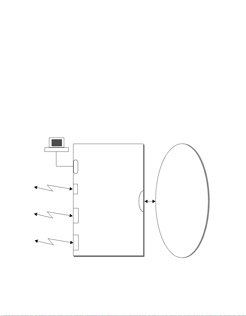
Router Module Operation
The router module (Figure 1-1) is designed to:
❑ Connect corporate networks and increase wide area connectivity .
❑ Support both synchronous and asynchronous routing over serial links
using one local area network (LAN) and up to three wide area
network (WAN) connectio n s .
❑ Provide flexible networking connections in multiprotocol
environments.
❑ Sit at the network’s logical and physical edge, either at a remote site
or central facility.
Edge Router Module
Console Port
Auxiliary
Port
Network
Backplane
High Speed
WAN Port
High Speed
WAN Port
Figure 1-1. Typical Edge Router Module Functions
1 - 2 Edge R outer Module Installation Guide for Token Ring
Token Ring LAN
Page 21

The router module runs Cisco standard software and fully interoperates
with the:
❑ 3Com ONline Ethernet Router Module
❑ Cisco local and remote router servers, such as the AGS+, MGS ,
and the Cisco 3000, 4000, 4500, and 7000 series.
Router Module Archi tecture
Each router module consists of two compo nents:
❑ Engine Module - Provides Token Ring-to-WAN port connections.
❑ Carrier Module - Provides connections to one of three 3Com
switching hub products.
The engine mounts to one of three carrier types to form an Edge Router
Module for th e ONline, ONsemble
, or ONcore hub products.
The architecture of each Edge Router Module type is illustrated in
Figure 1-2.
Introduction 1 - 3
Page 22
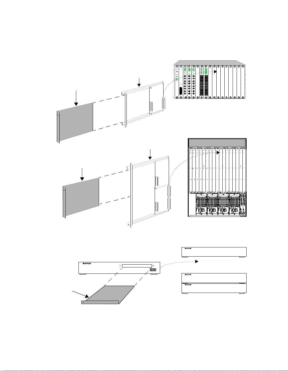
Edge Router Module
Engine
Edge Router Module
Engine
ONline
System Concentrator
ONline Carrier
ONcore
Switching Hub
ONcore Carrier
ONsemble Carrier
Edge Router Module
Engine
Figure 1-2. Edge Router Module Application in the ONline,
ONsemble, and ONcore Hubs
1 - 4 Edge R outer Module Installation Guide for Token Ring
ONsemble
StackSystem H u b
Page 23

Router Module Features
This section describes the major features of the router module , including:
❑ Softwa re O ptions
❑ Topology Switching Capability
❑ Network Reliability
❑ IOS Router Software Updates
❑ Memory Upgrades
Software Options
The router module provides a choice of four software feature sets:
❑ IP/IPX
❑ Desktop
❑ Desktop plus IBM
❑ Enterprise
Introduction 1 - 5
Page 24

Feature
Category
The compo nents which make up the software feature sets are listed in
Table 1-1.
Table 1-1. Software Feature Sets
Features In cluded per Feature Set
IP/IPX Desktop
Desktop plus
IBM
Enterprise
LAN Support IP,
Bridging,
LAN
Extension,
Host
Software,
Novell
IPX
®
™
IP, Bridging,
LAN
Extension,
Host
Software,
Novell IPX,
DECnet
™
IV,
Appletalk®
IP, Bridging, LAN
Extension, Host
Software,
Novell IPX,
DECnet IV,
AppleTalk Phase
1 and 2
Phase 1
and 2
WAN Serial
Dual Synchronous Ports, Single Asynchronous A uxiliary Port
Support
WAN Services HDLC, PPP, X.25, Frame Relay , SMDS
WAN
Optimization
Header and link compression, dial-on-d emand, dial backup,
bandwidth-on-demand, custom and priority queuing, access lists,
access security
™
IP Routing RIP, IGRP
, Enhanced IGRP, OSPF, BGP, EG P,
PIM
IP, B ridging, LAN
Extension, Host
Softwa re, Novell
IPX, DEC net IV,
AppleTalk Phase 1
and 2, DECnet V,
XNS, Banyan
VINES™, OSI,
Apoll o® Domain
RIP, IGRP,
Enhanced IGRP,
OSPF, BGP, EGP,
PIM, ES-IS, IS-IS
1 - 6 Edge R outer Module Installation Guide for Token Ring
Page 25

Feature
Category
Table 1-1. Software Feature Sets (Continued)
Features In cluded per Feature Set
IP/IPX Desktop
Desktop plus
IBM
Enterprise
IBM Support
Network
Management
Protocol
Translation
Autoinstall, SNMP, TELNET
Remote
source-route
bridging , proxy,
explorer,
local acknowledgment, SNA
local LU address
prioritizing,
administrative
filtering,
NetBIOS
™
name
caching,
NetBIOS access
control filtering
Remote
source-route
bridging, proxy,
explorer, local
acknowledgme nt,
SNA local LU
address
prioritizing,
administrative
filtering, NetBIOS
name caching,
NetBIOS access
control filtering,
serial tunneling
for SDLC Transport,
SDLC link-level
support, SDLLC,
TG/CO S, QLLC
TELNET, LA T,
rlogin, TN3270,
X.25
Introduction 1 - 7
Page 26

Topology Switching Capability
The router module provides to pology switching capability. Topology
switching is the ability to switch the router module between token rin g
networks (rings) on the hub backplane using:
❑ Network management module commands
❑ Simple Network Manag ement Protocol (SNMP)
You do not have to swap cables or move the router module to move the
routing or brid ging function s to a different network within the hub. You
can enter a command throu gh one of the 3Com management modules
and the network change is made automatically.
Network Reliability
The router module provides the capability to implement several levels of
reliability in your network:
❑ By configuring the router module’s WAN and auxiliary ports in
parallel, you can create up to three redundant serial links to protect
your mission-critical applications.
❑ You can config ure up to two backup links to ensure that your
applications are available if the primary link fails.
An example of the router module configured to provide reliability is shown
in Figure 1-3. These serial links can also support load-balancing to augment
the performance of y our network.
1 - 8 Edge R outer Module Installation Guide for Token Ring
Page 27
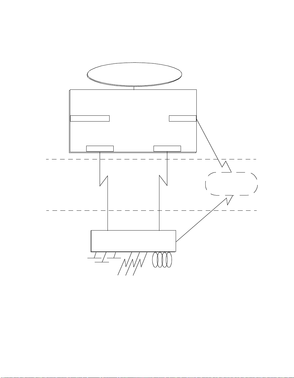
Token Ring
Edge Router Module
Remote Site
Main Site
Console Port
WAN Port
Primary
Link
Main Site Network Connections
Secondary
Link
Main Site Router
Aux Port
WAN Port
Dial-Up
Link
Public
Switched
Telephone
Network
Figure 1-3. Network Reliability Configuration
Introduction 1 - 9
Page 28

IOS Router Software Updates
The IOS software in the router module engine can be updated by
purchasing field-upgradable software distribution kits. Update your module
to the latest 3Com release of IOS software by downloading new code to
flash memory on the module. New updates are shipped automatically as
part of the 3Com 1-year Router Software Subscription Service or you can
purchase it from 3Com as a single unit update.
You can also purchase an upgrade kit to upgrade your IP/IPX, Desktop, or
Desktop plus IBM
Contact your 3Com reseller or 3Com Customer Support for more
information and part numbers.
Memory Upgrades
The router module provides the capability to increase memory to meet the
requirements of large routing table configurations.
Memory is configured on the router module to match the requirements of
the selected IOS software feature set. Table 1-2 lists the base memory
configurations for each softw are feature set.
Table 1-2. Memory Configurations
Memory
Type
IP/IPX Desktop
software to a version with an enhanced feature set.
Feature Set
Desktop
plus
IBM
Enterprise
IOS (Flash
EPROM)
Data (DRAM) 4 MB (expandable to 16 MB) 6 MB (expandable to 18 MB)
1 - 10 Ed ge Router Module Instal lation Guide for Token Ring
4 MB (expandable
to 8 MB)
8 MB
Page 29

2
Installing and
Configuring the Edge
Router Module
This chapter contains the following sections:
❑ Installation Overview
❑ Precautionary Procedures
❑ Quick Installation
❑ Unpacking Procedures
❑ Verifying Jumper Plug Positions
❑ Configuring the Router Module in an Unmanaged Hu b
❑ Installing the Router Module
❑ Configuring the Router Module in a Managed Hub
Note: The information and procedures presented in this chapter
are to be used only by trained servic e person nel to install
and maintain all models of the Edge Router Module.
Installing and C onfiguring the Edge Router Module 2 - 1
Page 30
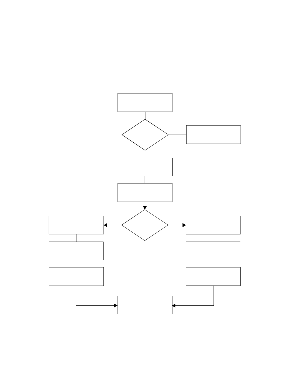
Installation Overview
The flowchart in Figure 2-1 identifies the steps that are required to install
the router module in a managed hub and in an unmanaged hub.
Read Precautionary
Procedures
(page 2-3 )
Install the Module
(page 2-11)
Configure the Engine
Using Cisco Commands
(page 2-22)
Configure the Carrier
Using NMM Commands
(page 2-22)
Experienced
Installer?
No
Unpack the Module
(page 2-5)
Verify Jumper Plug
Positions
(page 2-6)
Yes No
Managed
Hub?
Yes
Go to Quick Installation
(page 2-4)
Configure the Carrier
Using DIP Switches
(page 2-7)
Install the Module
(page 2-11)
Configure the Engin e
Using Cisco Commands
(page 2-22)
Installation Complete
Figure 2-1. Installing and Configuring the Edge Router Module
2 - 2 Edge R outer Module Installation Guide for Token Ring
Page 31

Precautionary Procedures
Electrostatic discharge (ESD) can damage static-sensitive devices on circuit
boards. Follow these precautions when you handle the ONline or ONcore
router modules:
Caution: Do not remove the product from any antistatic
wrapping until you are ready to inspect or install it.
Caution: Handle the product by the faceplate only.
Use proper grounding techniques whenever you handle the router module:
❑ Using a foot strap and grounded mat or wearing a grounded static
discharge wrist stra p .
❑ Touching the grounded rack or other source of ground just before
you handle the product.
Troubleshoot ing Installation Problems
If you encounter problems when you attempt to install and configure the
Edge Router Module, refer to the troubleshooting techniques in Chapter 4.
Installing and C onfiguring the Edge Router Module 2 - 3
Page 32

Quick Install atio n
Table 2-1 outlines the steps necessary to complete the installation of the
Edge Router Module. If you are already familiar with the procedures
required to install a router module in your 3Com hub type, use this table as
a checklist. Otherwise, use the procedures specified in the remainder of this
chapter to install th e router module.
Table 2-1. Quick Installation Steps
Step Proce dure Refer to:
1 Unpack the module. Unpacking Procedures
2 V erify jumper plug positions on the carrier and
engine.
3 Configure the carrier for operation in an
unmanaged hub (if necessary) using DIP switch
settings. If you have a network management
module installed in the hub, go to step 4.
4 Insert the module into an open slot in the hub, or,
for the ONsemble Edge Router Module, connect
the StackJack cables between ONsemble hubs.
5 Attach a manageme nt terminal to the console
port on the router module.
6 Configure the engine using Cisco Systems setup
command.
7 Configure the carrier using network management
module commands.
8 Attach WA N cables to the 60-pin universal W AN
connectors on the front panel.
Configuring the Router
Module in a n
Unmanaged Hub
Configuring the Carrier in
an Unmanaged Hub
Installing the ONline
Edge Router Mo dule (or
equivalent section for
your hub type)
Configuring the Router
Module in a n
Unmanaged Hub
Cisco Systems Getting
Started Guide
Configuring the Carrier in
a Managed Hub
Connecting WAN Cables
2 - 4 Edge R outer Module Installation Guide for Token Ring
Page 33

Unpacking Procedures
To unpack the Edge Router Module:
1. Verify that the module is the model you ordered by ch ecking the
model number listed on the side of the shipping carton.
Note that the product model number printed on the shipping box
differs from the model number on the product. The model number
on the shipping box contains the prefix ‘3C9’.
2. Remove the module, in its antistatic bag, from the shipping carton.
3. Remove the module from the antistatic shielding bag and inspect it
for damage.
Always handle the module by the faceplate, being careful not to
touch the components. If the module appears to be damaged, return
it to the antistatic shielding bag, repack it in the shipping carton, and
contact your local supplier.
4. V erify that the contents of the shipment are complete. The shipment
contents are listed below:
❑ Edge Router Mod ule (may be fully assembled or shipp e d as
separate carrier and engine)
❑ Edge Router M odule Installation Guide
❑ Release Notes for the Edge Router Module
5. Store the shipping cartons and antistatic wrapping so that you can
repackage the product for storage or shipment.
Installing and C onfiguring the Edge Router Module 2 - 5
Page 34

Verifyin g the Jumper Plug Positi ons
Verify the jumper plug positions of the router module engine before
proceeding with the installation procedure.
The Edge Router Module is equipped with several jumper plugs. The
jumpers are factory-set to the appropriate settings. Do not modify the
jumper settings, except to restore the settings to the required positions.
Caution: If you modify any of th e factory-set jumper positions,
the router module may not operate properly.
Verifying Jumper Plug Positions on the Engine
Figure 2-2 shows the jumper plug locations on the router module engine.
J1
J1
J4
J4
J3
J8
J3
J8
J10
J9
J11
J10
J9
J11
Figure 2-2. Engine Jumper Plug Locations
2 - 6 Edge R outer Module Installation Guide for Token Ring
P1
P1
Page 35

Table 2-2 lists the default positions of the jumper plugs on the engine.
Verify the jumper plug positions specified in Table 2-2.
Table 2-2. Default Engine Jumper Plug Settings
Jumper Jumper Plug Position
J1 Removed
J3 Installed
J4 Removed
J8 Installed
J9 Removed
J10 Installed
J11 Removed
P1 Block As shown
Configuring the Router Module in an Unmanaged Hub
If you use a network management module to manage your hub, go to the
next section, Installing the Router Module.
If you do not use a network manageme nt module to manage your hub,
configure the router mod ule by completing each of the following tasks:
❑ Configurin g the carrier by setting DIP switches.
❑ Configuring the engine using Cisco Systems commands (refer to the
section Configuring the Edge Router Module Engine on
page 2-22).
Installing and C onfiguring the Edge Router Module 2 - 7
Page 36

Configuring the ONline Carrier in an Unmanaged Hub
This section includes the following sections:
❑ Locating the ONline Carrier DIP Switches
❑ Selecting a Backplane Network
❑ Setting the Ring Speed
❑ Isolating the Router Module
Locating the ONline Carrier DIP Switches
Figure 2-3 shows the location and default positions of the ONline Carrier
DIP switches.
ONOFF
Single/Multiple Rings
Ring Speed
Backplane Enable
1
2
3
4
5
6
7
8
Figure 2-3. ONline Carrier DIP Switch Location
2 - 8 Edge R outer Module Installation Guide for Token Ring
Page 37

Table 2-3 defines the function of each ONline Carrier DI P switch.
Table 2-3. ONline Carrier DIP Switch Settings
Switch Setting
Factory
Switch Function
Default
On Off
Backplane Network
1
Single/Multiple Rings
Single
Ring
Single
Ring
Multiple
Rings
2 Ring Spee d 16 Mbps 4 Mbps 16 Mbps
3 Backplane Enable Enable Enable Disable
4 to 8 Reserved – Do Not
Off N/A N/A
Change
Configure the ONline Carrier DIP switches acc ording to the guidelines
provided in the foll owing sections.
Selecting a Backplane Network
T o connect the router module to a specific backplane network ring, use DIP
switch 1. In an unmanaged hub, you can connect the router module to one
network ring t hat includes all slots in the hub (Single Ring) or to one of
three network rings (Multiple Rings).
Set DIP switch 1, Single/Multiple Rings, as follows:
❑ Single Ring (Dip Switch 1 ON) – When all modules in an
unmanaged hub are set to Single Ring, the hub slots form a single
backplane ring. Insert the router module in any available slot to
connect to the ring.
❑ Multiple Rings (Dip Switch 1 OFF) – When all modules in an
unmanaged hub are set to Multiple Rings, the hub slots are grouped
into three separate rings, as shown in Table 2-4.
Installing and C onfiguring the Edge Router Module 2 - 9
Page 38

Table 2-4. ONline Slot Assignments for Multiple Rings
Slot Assignments
Ring Number
17-Slot Hub 6-Slot Hub
1 Slots 1, 2, and 3 Slots 1, 2, and 3
2 Slots 4 through 9 Slots 4, 5, and 6
3 Slots 10 through 15
a. Slots 16 and 17 are not assigned to a backplane ring in unmanaged hubs.
a
N/A
In a 17-slot hub, for example, to connect the router modu le to
backplane ring 1, install the module in slots 1, 2, or 3. T o connect the
router module to backplane ring 2, install the module in any slot from
4 through 9.
If the router module is installed in the hub after powerup, you must
re-initialize the hub backplane before the router module can join the
ring. T o re-initialize the backplane, press the LED Test switch three
times in rapid su ccession.
Caution: Set DIP switch 1 on all Edge Router Modules in the hub
to the same setting. Otherwise, unpredictable results
may occur.
Setting the Ring Speed
To set the token ring speed for the carrier, use DIP switch 2. Be sure to set
the carrier ring speed to m at ch that of the router module engine and all
other modules attach ed to th e same b ac kplane ring.
T o set the carrier ring speed, position DIP switch 2 as described in T able 2-3.
2 - 10 Ed ge Router Module Instal lation Guide for Token Ring
Page 39

Isolating the Router Module
T o isolate the router module from the backplane network ring to which it is
connected, use DIP switch 3.
To isolate the router module, set DIP switch 3 to Off. To connect the router
module to the s elected backplane network ring, set DIP switch 3 to On.
Installing the Router Module
This section provides procedures for installing the router module into a hub
or stack, including:
❑ Installing the ONline Edge Ro uter Module
❑ Installing the ONsemble Edge Rou ter Module
Installing the ONlin e Edge Router Module
This section describes how to install the Edge Router Module in a 3Com
ONline System Concentrator. It contain s the following sections:
❑ Installing the Router Module
❑ Re-initializing the Backplane
You can also install the ONline Edge Router Module into an ONcore hub.
For information on installing ONline modules into the ONcore hub, refer to
the ONcore Switching Hub Installation and Operation Guide (Document
Number 17-00362).
Installing the Edge Router Modu le
Note: You do not need to power dow n the hub to install or
remove the module. You can insert the module while the
hub is operating (this is called a hot swap).
Installing and Configuring the Edge Router Module 2 - 11
Page 40

To install the module:
1. Properly ground yourself prior to handling the router module. For
example, wear a static wrist guard or touch a grounded static mat
prior to handling the module.
2. Locate an open slot in the hub. If necessary , remove a blank panel on
the hub to expose a slot.
3. Insert the router module into the board guides at the top and bottom
of the slot and slide it into the hub by pressing firmly at the top and
bottom of the faceplate. Make sure the connectors are well-seated
into the backplane of the hub. Using your fingers, tighten the screws
on the front of the router module faceplate (Figure 2-4 ).
Figure 2-4. Inserting a Module into an ONline Hub
Re-initializing the Backplane
If you insert the router module into an unmanaged concentrator, the new
module cannot communicate with other modules in the concentrator until
you re-initialize the backplane.
To re-initialize the backplane , press the LED check button on the ONline
Controller Module three times rapidly . A clicking sound indicates that the
backplane is being re-initialized.
2 - 12 Ed ge Router Module Instal lation Guide for Token Ring
Page 41

Note: If the engine module does no t connect to the backplane
network ring when you insert the router module, ensure
that both the engine and the carrier are set to the ring
speed of the backplane network ring.
Installing the ONsemb le Edge Router Modu le
This section describes how to install th e router module in an ONsemble
StackSystem
❑ Before You Inst all the ONsemble Edge Router Modul e
❑ Installing the Edge Router Module in t he ONsemble Hub Stack
™
Token Ring hub stack. It contains the following sections:
Before You Install the ONsemble Edge Router Module
This section provides information you need to know before you install the
ONsemble Edge Router Module.
❑ ONsemble Overview — If you are not familiar with the ONsemble
StackSystem Token Ring Hub, review the ONsem ble StackSystem
T oken Ring Hub Installation and Operation Guide for information on
the following topics:
™
– 3Com StackJack
– Hub IDs
❑ ONsem ble Power Requi rement s — Make sure the circuit you plan
to use can supply adequate power . Maximum power consumption by
the Edge Router Module is approximately 75 Watts.
Cabling
❑ ONsemble Hub Stacks Rules — A hub stack must comply with the
following rules:
– A stack mounted on a tabletop or in an equipment rack
can contain up to 8 hubs (the Edge Router Module counts
as 1 hub).
Installing and Configuring the Edge Router Module 2 - 13
Page 42

Caution: If you stack hubs on the floor , regulatory agency safety
requir ements limit the stack size to 6 hubs.
– The maximum length for all StackJack cables combined
is 80 meters.
Installing the ONsemble Edge Router Module in a Hub Stack
This section describes how to add the Edge Router Module to a hub stack.
To add the router module hub to a hub stack:
1. Select a stack position for the router m odule hub.
To preserve the existing hub ID assignments, add the router module
hub to the top of the hub stack (assuming the management hub is
located on the bottom).
In typical installations, the hub at the top of the stack has the highest
hub ID. Figure 2-5 shows a typical installation.
ONsemble Edge
Router Module
Hub IDs
Figure 2-5. Typical Hub Installation
2. Position the router module in the hub stack.
3. Connect power to the router module (Figure 2-6).
2 - 14 Ed ge Router Module Instal lation Guide for Token Ring
Hub with Highest
Hub ID Prior to
Addition of the
Edge Router
Module
Management Hub
Page 43

Figure 2-6. Connecting Power to the Edge Router Module
4. Disconnect the StackJack cable from the StackJack Out connector on
the hub next to the router module.
5. Reconnect the StackJack cable to the StackJack Out connector on the
router module (Figure 2-7) .
ONsemble Edge
Router Module
Reconnected
StackJack Cable
Figure 2-7. Reconnected StackJack Cable
6. Connect one end of the StackJack cable that shipped with the router
module to the StackJack In connector o n the router module.
7. Connect the other end of the new StackJack cable to the StackJack
Out connector on the hub next to the router module (Figure 2-8).
Installing and Configuring the Edge Router Module 2 - 15
Page 44

ONsemble Edge
Router Module
New
StackJack Cable
Figure 2-8. Connecting the New StackJa ck Cable
8. Check LEDs to verify proper operation.
The Stack In and Out LEDs on the router module:
❑ Light solid yellow until the management hub establishes contact
with the router module.
❑ Light solid green to indicate proper operation.
9. If desired, change the hub ID.
The management hub should automatically assign the router module
the lowest unu sed hub ID.
To change the hub ID, use a thin, blunt object to press the recessed
Hub ID switch on the router modu le front panel (Figure 2-9).
Each time you press the switch, the hub ID displays the letter C and
then increases by one. When the hub ID is 8, pressing the switch
changes the hub ID to 0.
Note: Hub ID 0 is not a valid hub ID and hub ID 1 is typically used
as the ID for the ONsemble management hub. If you
change the hub ID , change it to an unused value from
2 to 8.
2 - 16 Ed ge Router Module Instal lation Guide for Token Ring
Page 45

Hub ID Switch
Figure 2-9. Hub ID Switch Location
You can also use the SET HUB management command to change
hub IDs. For details, refer to the ONsemble StackSystem Token Ring
Hub Management Guide.
Configurin g the Router M od ule i n a Manag ed Hub
Use the procedures in this section to configure the Edge Router Module in
a managed hub. Thi s secti on includes the following topics:
❑ Managed Configuration Overview
❑ Attaching a Manag em ent Term inal
❑ Configuring the Edge Router Module Engine
❑ Configuring the Edge Router Module Carrier
Installing and Configuring the Edge Router Module 2 - 17
Page 46

Managed Configuration Overview
A managed configuration is one in which a network management module
is installed. Use the following procedure to configure the router module in
a managed configuration:
1. Attach a management terminal to the engine consol e or auxiliary
port and attach a management terminal to the hub management
module console port.
2. Use the terminal to configure the engine usin g Cisco Systems
commands.
3. Use the terminal to configure the carrier using 3 Com network
management module commands.
Note: Be sure to set the ring speed of both the engine and the
carrier to match the rin g speed of the network ring to
which the router module will be connected.
Attaching a Management Terminal
Use a terminal (or workstation running a terminal emulation program) to
configure both the router module engine and the router module carrier:
❑ Engine — Attach the terminal to the console or auxiliary port on the
engine.
❑ Carrier — Attach the terminal to the console port on the network
management module for the hub.
Note: You can also TELNE T to the m anagement modu le hub.
Refer to the documentation for your management module
for information.
2 - 18 Ed ge Router Module Instal lation Guide for Token Ring
Page 47

Attaching a Terminal to the Console Port of the Engine
Attach a terminal to the Edge Router Module console port to configure or
modify the engin e para me ters .
To attach a termin al t o the console port:
1. Insert the mini-DIN end of the 3Com OpenHub Managem ent
Modem Adapter Cable into the circular Console connector on the
router module.
2. Attach one end of the RS-232 null modem cable to a COM
(communications) port on your terminal. Attach the other end to the
DB-25 end of the OpenHub Management Mod em Adapter cable.
Figure 2-10 illustrates the cable connection to the router module console
port in an ONline hub.
Mini-DIN
Connector
DB-25
Connector
To Termi nal
COM Port
3Com OpenHub
ONline
System
Management Modem
Adapter Cable
Null Modem
Cable
Figure 2-10. Attaching a Terminal to the Engine Console Port
Installing and Configuring the Edge Router Module 2 - 19
Page 48

Attaching a Terminal to the Auxiliary Port of the Engine
Attach a terminal to the Edge Router Module auxiliary port to configure or
modify the engin e para me ters .
To attach a termin al t o the auxiliary port:
1. Insert the mini-DIN end of the 3Com OpenHub Management Modem
Adapter Cable into the circular Auxiliary c onnector on the router
module.
2. Attach the DB-25 end of the modem adapter cable to an RS-2 32
modem cable coming from a COM port on your terminal.
Figure 2-11 illustrates the cable connection to the router module auxiliary
port in an ONline hub.
.
Mini-DIN
Connector
DB-25
Connector
To Terminal
COM Port
3Com OpenHub
ONline
System
Management Modem
Adapter Cable
Figure 2-11. Attaching a Terminal to the Engine Auxiliary Port
2 - 20 Ed ge Router Module Instal lation Guide for Token Ring
Null Modem
Cable
Page 49

Attaching a Terminal to the Management Module
Attach a terminal to the console port on the network management module
to configure or mo dify carrier parameters for t he Edge Router Module.
Note: Y ou can use one terminal for connections to both the Edge
Router Module and to the network management module.
To connect the terminal to the network m an agement module (NMM):
1. Attach one end of an RS-232 null modem cable to the console port of
the NMM.
2. Attach the other end of the null modem cable to a COM port on your
terminal. Figure 2-12 shows the terminal con nections to both the
NMM and the Edge Router Module consoles.
Figure 2-12. Terminal Connections to the NMM and Edge Router
Module Console Ports
Installing and Configuring the Edge Router Module 2 - 21
Page 50

Configuring the Edge Router Module Engine
Use the management terminal to configure the router module engine using
Cisco Systems 2500-series router command s.
For procedures to configure your router module engine, refer to one of the
following sources:
❑ If you have hardcopy versions of the Cisco Systems
set, refer to the Getting Started Guide and the Rout e r Products
Configuration Guide for your software version on the Cisco Systems
UniverCD™ CD-ROM disk.
❑ If you do not have hardcopy versions of the Cisco Systems
documentation set, refer to the Getting Started Guide and the
Router Products Configuration Guide for your software version on
the Cisco Systems UniverCD CD -ROM disk.
Note: Be sure to set the ring speed of the engine to match that of
the carrier before proceeding with the installation.
Configuring the Edge Router Module Carrier
3Com network management modules (NMMs) provide network
management and configuration capabilities for 3Com hub-based products,
including the Edge Router Module carrier.
Note: If you have not attached a terminal for network
management, refer to the section Attaching a
Management Terminal on page 2-18.
®
documentation
This section provides procedures for configuring the carrier of the following
hub types:
❑ ONline
❑ ONsemble
2 - 22 Ed ge Router Module Instal lation Guide for Token Ring
Page 51

Configuring the ONline Carrier in a Managed Hub
To configure an ONline carrier:
1. Set the Token Ring Speed
Set the ring speed of the carrier to match the ring speed of the router
module engine and the backplane token ring network to which it will
be connected.
The default ring speed for the both the carrier and the engine is
16 Mbps. If the ring speed of either the carrier or the engine does not
match the ring speed of the netw ork to which it is connected, the
router module is automatically isolated from the network.
Set ring speed for the carrier by issuing the following NMM
command:
ONline> set mo du le {slot} ring_speed {4MBPS}
{16MBPS}
2. Select a Network Ring
Assign the Edge Router Modules backplane port to one of the
followin g connections:
❑ One of seven backp lane token ring networks
❑ Isolated mode
Refer to the ONline System Concentrator Installation and Operation
Guide, Chapter 1, for an ONline backplane a rchitecture description.
Assign the carrier to a network ring by issuing the following NMM
command:
ONline> set mo du le {slot} network {token_ring_1..._7}
{isolated}
Note: You may see a message o n the engine management
console indicating a momentary “Wire Fault” condition on
the token ring port. This is a normal condition that occurs
when you switch the router module bet ween backplane
rings or in and ou t of isolated mode.
Installing and Configuring the Edge Router Module 2 - 23
Page 52

3. Save the Carrier Configuration
Save the carrier configuration to preserve any ch anges you have
made.
Save the carrier configuration by issuing the following N MM
command:
ONline> save all
Note: Failure to save carrier settings may result in loss of
configuration data.
For detailed information on configuring the ONline Carrier, refer to the
ONline Token Ring Carrier Assembly and Configuration Guide or contact
your local 3Com reseller.
Configuring the ONsemble Carrier
To configure an ONsemble carrier.
1. Set Token Ring Speed
Set the ring speed of the carrier to match that of the router module
engine and all other stations on the ring. If you installed the carrier in
a hub stack that is running at a different ring speed, or if you have
not set the carrier ring speed to match that of the engine, the router
module is automatically isolated from the stack. The default ring
speed for the carrier is 16 Mbps.
If necessary , use the following procedure to change the ring speed of
the ONsemble carrier:
a. Use the SET PORT MODE command to d isable all ports on the
carrier. For example:
ONsemble> set port 4.all mode disable
Port 04.01 set to DISABLED.
Port 04.02 set to DISABLED.
2 - 24 Ed ge Router Module Instal lation Guide for Token Ring
Page 53

b. Use the SET TRUNK MODE command to disable the StackJack
trunks on the carrier. For example:
ONsemble> set trunk 4 stackjack_in mode disable
Trunk 04 stackjack_in set to DISABLED.
prompt> set trunk 4 stackjack_out mode disable
Trunk 04 stackjack_out set to DISABLED.
c. Use the SET HUB NETWORK command to assign th e carrier
network to token_ring_1. For example:
ONsemble> set hub 4 network token_ring_1
Hub 4 network id set to TOKEN_RING_1.
d. Enter the SET HUB RING_SPEED command. For ex am ple:
ONsemble> set hub 4 ri ng _sp eed 4mbp s
Ring Speed set to 4 MBPS.
e. E nable all ports on the carrier. For example:
ONsemble> set port 4.all mode enable
Port 04.01 set to ENABLED.
Port 04.02 set to ENABLED.
f. Enable StackJack trunks on the carrier. For example:
ONsemble> set trunk 4 stackjack_in mode enable
Trunk 04 stackjack_in set to ENABLED.
prompt> set trunk 4 stackjack_out mode enable
Trunk 04 stackjack_out set to ENABLED.
2. Set the Network Connection.
By default, the ONsemble Carrier is assigned to token_ring_1.
You can assign the carrier to one of two netwo rk connections:
❑ token_ring_1 – All hubs within a stack assigned to the
token_ring_1 network are on the same ring and co mmun icate
with each other through their StackJack connections. You can
also extend token_ring_1 to other hub stacks by using a
ring-in/ring-out device such as the ONsemble Token Ring Fiber
Ring-In /Ring-Out Module.
Installing and Configuring the Edge Router Module 2 - 25
Page 54

❑ isolated – A hub assigned to the isolated network does not
communicate with other hubs through the StackJack
connections. However, the management hub can still manage
the hub through the separate StackJack management data path.
Change the network connection of the ONsemble carrier by issuing
the SET HUB N ETWORK command, as in the following example:
ONsemble> set hub 4 network isolated
Hub 4 network id set to ISOLATED.
Note: You may see a message o n the engine management
console indicating a momentary “Wire Fault” condition on
the token ring port. This is a normal condition that occurs
when you switch the router module bet ween backplane
rings or in and ou t of isolated mode.
3. Save the Carrier Configuration
To preserve any changes you made , issue the following command:
ONsemble> save all
Note: Failure to save carrier settings may result in loss of
configuration data.
For detailed information on configuring the ONsemble Carrier , r efer to the
ONsemble Token Ring Carrier Assembly and Configuration Guide or
contact your local 3Com reseller.
2 - 26 Ed ge Router Module Instal lation Guide for Token Ring
Page 55

3
Using the Edge Router
Module
This chapter provides procedures for tasks you may need to perform while
using the Edge Router Module.
Note: For engine-related troubleshooting information, refer to the
appropriate Cisco Systems manual.
This chapter contains the following sections:
❑ Showing t he Router Module Configuration and Status
❑ Monitoring Router Module Operation
❑ Recovering a Lost Password
❑ Updating or U pgrading IOS Software
❑ Increasing Operating Memory
Note: The information and procedures presented in this chapter
are to be used only by trained servic e person nel to install
and maintain all models of the Edge Router Module.
Using the Edge Router Module 3 - 1
Page 56

Showing the Router Module Configuration and Status
This section includes the following topics:
❑ Showing t he Engine Configuration and Status
❑ Showing the Carrier Configuration and Status
Showing the Engine Configuration and Status
To monitor th e configuration and status of the Edge Ro uter Module
engine, use Cisco Systems 2500-series router commands. Refer to the Cisco
Systems UniverCD CD -ROM disk or to the Cisco Systems Getting Started
Guide for information.
Showing the Carrier Configuration and Status
To show carrier configuration and status, use the following comm ands:
❑ SHOW MODULE
❑ SHOW PORT
Using the SHOW MODULE Command
The SHOW MODULE command displays information about a particular
carrier.
The syntax of the SHOW MO D UL E command is:
SHOW MODULE {slot} {verbose}
{no_verbose}
3 - 2 Edge R outer Module Installation Guide for Token Ring
Page 57

The following command displays example information on the carrier
installed in slot 6:
ONline> sh ow mo dul e 6 v er bos e
Slot Mod ul e V er sio n Net wo rk G en era l Inf or matio n
---- --- -- --- -- --- --- - -- --- - --- -- -- --- -- - - -- --- -- --- -- ----- 06 520 1M -SD EK v 1. 00 TOK EN _R ING _1 2 20 3R- CS E
5201M-SD EK : O Nl ine Toke n Rin g Car ri er En gi ne: 2 203 R- CSE Edg e Rtr E ntr SW
Ring Spe ed : 16 MB PS
Network St atu s: OK AY
Boot Ver si on: v1 .00
Module C ap abi li tie s: MA CCF G; IPC FG ;
No. Fron t Pan el Po rts: 2
Native S of twa re Ve rsion : v1 0.0 3
Native B oo t S of twa re Vers ion : v4 .14
No_Verbose is the default option for the SHOW MODULE command. Use
the No_Verbose option to display summary information for the carrier . The
following command displays example summary information on the carrier
installed in slot 6:
ONline> s how m odu le 6
Slot Mo du le Ve rsi on N etw or k Ge ner al In forma ti on
---- -- -- --- -- --- ---- -- --- -- - --- -- --- -- -- -- --- -- --- ----- -- - 06 52 01 M-S DE K v1 .00 T OKE N_ RIN G_ 1 22 03R -C SE
Using the Edge Router Module 3 - 3
Page 58

Using the SHOW PORT Command
ONline > show port 6.1
Port D isp la y f or Modu le 52 01M -S DE K:
Port Mod e S tatus N et wor k Gen er al In for ma tio n
----- --- -- --- - ----- --- -- --- -- -- - - -- --- -- --- - --- -- ----- --- -- --- -- --
06.01 LOG IC AL O KAY T OK EN_ RI NG_ 1 Bac kp lane
The SHOW PORT command displays information on a single port or all
ports.
The syntax for the SHOW PORT command is:
SHOW PORT {slot.port} {verbose}
{no_verbose}
The following command displays example informatio n for port 1 on the
carrier installed in slot 6:
ONline > show port 6.1 verbose
Port D isp la y f or Modu le 52 01M -S DEK :
Port Mod e S tatus N et wor k Gen er al In for ma tio n
----- --- -- --- - ----- --- -- --- -- --- - -- --- -- --- - --- -- ----- --- -- --- -- --
06.01 LOG IC AL O KAY T OK EN_ RI NG_ 1 Bac kp lane
Port C onn ec tor : B AC KPL AN E
IP Add res s: 1 51 .10 4. 30. 50
Statio n A dd res s: 0 0- 00- 30 -05 -0 0-0 8
Capabi lit ie s: - NO NE-
No_Verbose is the default option for the SHOW PORT command. Use the
No_Verbose option to display summary info rmation for the carrier ports.
The following command displays example summary information for port 1
on the carrier installed in slot 6:
3 - 4 Edge R outer Module Installation Guide for Token Ring
Page 59

Monitoring Ro u ter Mo dul e Op eratio n
This section provides information on the following topics:
❑ Monitoring the Engine LEDs
❑ Monitoring the ONsemble Carrier LEDs
Note: ONline and ONcore carriers are not equipped with LEDs.
Monitoring Engine LEDs
The LEDs on the front panel of the Edge Router Module engine allow you
to monitor the status of the module and ports. The following LED status
changes occur when you install the Edge Router Module in the hub:
1. The Router Status (RTR) LED is off if the router is booting (initializing).
2. The Router Status (RTR) LED illuminates once the router boot
software is running.
3. The Module Status (S) LED blinks while the router module engine
establishes communication with th e carrier.
4. The Module Status (S) LED stays illuminated once the r outer module
engine establishes communication with the carrier board.
Figure 3-1 shows the LED locations on an Edge Router Module engine as
installed on an ONline carrier . Each LED indicates the state of the module or
port as described in Table 3-1.
Using the Edge Router Module 3 - 5
Page 60

RTR
EO
TR
Reset
CONSOLE
Router Status
S
Module Status
Token Ring
Activity
Reset
Pushbutton
AUX
S0
ACT
S1
ACT
2203R-CS E
2103R-CS
Figure 3-1. Edge Router Module Engine LEDs
Serial Port 0
Activity
Serial Port 1
Activity
3 - 6 Edge R outer Module Installation Guide for Token Ring
Page 61

Table 3-1. Interpreting Router Module Engine LEDs
LED Name Color State Indicates
RTR
(Router Status)
S
(Module
Status)
TR Activity
(Token Ring
Activity)
S0 ACT
(Serial WAN
Port 0 Activity)
Green On Router is functioning properly.
Off or
Blinking
Green Blinking The router module engine is
On Remains lit as long as there is
Yellow Blinking Traffic is being passed on the
Yellow Blinking Traffic is being passed on
Router is not functioning.
Replace the router module or
the router module engi n e.
in boot mode and is
attempting to establish
communication with the
carrier board.
active communication with
the carrier board.
token ring LAN to which the
module is connected.
WAN Port 0.
S1 ACT
(Serial WAN
Port 1 Activity)
Yellow Blinking Traffic is being passed on
WAN Port 1.
Using the Edge Router Module 3 - 7
Page 62

Monitoring the ONsemble Carrier LEDs
This section describes how to use the ONsemble Carrier LEDs (Figure 3-2). It
contains the following sections:
❑ Testing the LEDs
❑ Interpreting the LEDs
LED Test Switch ONsemble Engine
Carrier LEDs
Figure 3-2. Edge Router Module ONsemble Carrier LEDs
Testing the LEDs
If an LED fails to light and you suspect a problem, test the LEDs before
performing additional troubleshooting procedures.
To test the LEDs:
1. Insert a thin, blunt object into the LED Test switch opening (see
Figure 3-2) on the hub front panel, press in the switc h, and release.
3 - 8 Edge R outer Module Installation Guide for Token Ring
Page 63

2. Observe the LED and verify that it lights as described below.
a. The following LEDs light green for 2 seco nds:
– BUPS
– Primary (top LED only)
– System (top LED only)
– 4 MB
– 16 MB
– Ports 1 and 2 (top LEDs only)
– Stack Out (top LED only)
– Stack In (top LED only)
– Isolated
b. The followin g LEDs light yellow fo r 2 seconds:
– Primary (bottom LED only)
– System (bottom LED only)
– Beacon
– Ports 1 and 2 (bottom LEDs only)
– Stack Out (bottom LED only)
– Stack In (bottom LED only)
c. The Hub ID display increment s by 1 from 0 to 8.
Note: The Power On LED and all Engine LEDs remain lit during the
entire LED test.
Using the Edge Router Module 3 - 9
Page 64

Interpreting the Carrier LEDs
This section describes how to interpret the ONsemble Carrier LEDs.
Table 3-2 describes how to interpret the Power On LED.
Table 3-2. Interpreting the Pow er On LED
LED
State
Green OnRouter module is
Green
Off
Indication Possible Cause Corrective Action
receiving power.
Router module is
not receiving
power.
Router mo dule
power cord is
disconnected.
Router mo dule
power cord is
defective.
Power outlet is not
supplying power.
Router mo dule
failure.
LED failure. Repair the router modul e.
Connect the power cord.
Replace the power cord.
Make sure that the power
outlet is supplying p ower
within the required range .
Repair the router modul e.
3 - 10 Ed ge Router Module Instal lation Guide for Token Ring
Page 65

Table 3-3 describes how to interpret the Primary LED.
Table 3-3. Interpreting the Primary LED
LED
State
Green OnInternal power
Yellow
Blink
(BUPS
only)
Indication Possible Cause Corrective Action
supply oper ating.
Internal power
supply failed.
Router module is
receiving power
from external
Backup Power
Supply (BUPS).
Router mo dule
power cord is
disconnected.
Router mo dule
power cord is
defective.
Power outlet is not
supplying power.
Router mo dule
failure.
Connect the power cord.
Replace the power cord.
Make sure that the power
outlet is supplying p ower
within the ranges specified in
Appendix A.
Repair the router modul e.
Using the Edge Router Module 3 - 11
Page 66

Table 3-4 describes how to interpret the BUPS LED.
Table 3-4. Interpreting the BUPS LED
LED
State
Green OnBackup power
Off Backup power not
Indication Possible Cause Corrective Action
available from
external Backup
Power Supply
(BUPS).
available from
external BUPS.
BUPS not installed. The BUPS is an optional
StackSystem component
that provides backup power
protection for u p to eight
StackSystem components.
You can connect a BUPS to
any component that has an
installed Power Interface
Card (PIC).
Loose, improperly
connected, or
disconnected BUPS
cable.
Make sure that the BUPS
cable is connected co rrectly
and is not loose .
BUPS supplying
power to a hub with
a failed power
supply .
LED failure. Perform LED test (refer to
3 - 12 Ed ge Router Module Instal lation Guide for Token Ring
Replace the faulty hub.
Testing the LEDs on
page 3 -8).
Page 67

Table 3-5 describes how to interpret the System LED.
Table 3-5. Interpreting the System LED
LED
State
Green OnRouter module OK
Green
Blink
Indication Possible Cause Corrective Action
and is currently
managed by the
management hub.
Router module OK,
but cannot
communicate with
the management
hub through the
StackJack
connection.
Loose, improperly
connected, or
disconnected
StackJack cable.
Management hub
powered off.
Management hub
failure.
Incorrect cable used
for StackJack cable.
Check StackJack LEDs. Make
sure all StackJack cables are
connected correctly and not
loose.
Power up the management
hub.
Check management hub
status. If necessary, replace
management hub.
Replace incorrect StackJack
cable with a cable that meets
specifications in ONs emble
Token Ring Hub Installation
and Operation Guide.
Faulty StackJack
connector.
Using the Edge Router Module 3 - 13
Repair the router modul e.
Page 68

Table 3-5. Interpreting the System LED (Continued)
LED
State
Yellow OnIn-band software
Yellow
Blink
Indication Possible Cause Corrective Action
download in
progress.
Management hub
setting up
StackJack
connections to
router module.
If the LED remains
yellow for more
than 1 minut e,
the management
hub is unable to
set up a StackJack
management
connection to
router module.
Test failed. Router
module m ay not
be operational.
Normal but
temporary condition.
Faulty cable. Replace StackJack cables
Hardware failure. Repair the router module.
Improper software
initialization.
None required.
one at a time. Allow
1 minute between each
replacement for the problem
to clear.
Try recycling power once. If
the test still fails, seek
technical assistance.
Allowed internal
operating
temperature
exceeded.
Hardware failure. Repair the router module.
Off Not used. LED failure. Repair the router module.
Table 3-6 describes how to interpret the Beacon LED.
3 - 14 Ed ge Router Module Instal lation Guide for Token Ring
Make sure fans are
operating. If not, have
router module repaired.
Make sure operating
temperature of external
environment is within
specifications.
Page 69

Table 3-6. Interpreting the Beacon LED
LED
State
Off Router module ring
Yellow OnRouter module ring
Indication Possible Cause Corrective Action
is not beaconing.
is beaconing.
The beacon
recovery feature
corrects this
condition. Unless
beacon recovery is
disabled, this LED
should light only
for a short period
of time.
Cabling failure. Check the lobe cable
connections at all connection
points.
Check the connection points
of Ring-In /Ring-Out trunks,
if present in the stack.
NIC failure. Make sure all NICs are
installed and operating
properly. Check the port
LEDs to help identi fy the
faulty NIC.
Speed detection
disabled and station
inserted into ring at
incorrect speed.
Enable speed detection (SET
PORT SPEED_DETECT) and
make sure all NICs are set to
the same ring speed.
Recovery is disabled. Enable beacon recovery.
Table 3-7 descr ibes how to interpret the Speed LED.
Table 3-7. Interpreting the Speed LED
LED State Indication Possible Cause Corrective Action
Green On
(4 MB or
16 MB)
The two internal token
ring ports are running
at the indicated speed
(4 Mbps or 16 Mbps).
Using the Edge Router Module 3 - 15
Page 70

Table 3-8 describes how to interpret the Port LEDs.
Table 3-8. Interpreting Port LEDs
LED
State
Green OnPort enabled and
Green
Blink
Indication Possible Cause Corrective Action
attached station
inserted in ring.
Port enabled but
attached station
not inserted.
(Phantom current
is not detected.)
No station is
connected.
The station is
powered off or the
NIC is not operating.
Incorrect lobe
cabling.
Faulty lobe port. Try a secon d port. If the
Lobe cable is
disconnected.
If desired, connect a station.
Make sure the station is
powered up and the NIC is
operating correctly.
Make sure the correct cable
is plugged into the hub port
and the station is plugged
into the correct wall jack.
second port works, the
original port needs to be
repaired.
Make sure the lobe cable is
connected at the hub and at
the NIC.
In active hubs only,
the station is running
at the incorrect
speed.
3 - 16 Ed ge Router Module Instal lation Guide for Token Ring
Make sure that the speed of
the connected station
matches the hub ring speed.
Page 71

Table 3-8. Interpreting Port LEDs (Continued)
LED
State
Yellow OnPort automatically
Yellow
Blink
Indication Possible Cause Corrective Action
disabled due to
security breach.
Port automatically
disabled due to
beaconing
conditio n or
connected station
running a t
incorrect ring
speed.
The security feature
is enabled and a
station with an
unauthorized MAC
address attempted
to insert into the
ring.
NIC is set to incorrect
ring speed.
Ring is beaconing. Beaconing is typically due to
Reconfigure the security
settings to allow th e
newly-connect ed station to
use this port. For
instructions, refer to the
ONsemble StackSystem
Token Ring Hub
Management Guide.
Make sure the NIC is
configured for the same ring
speed as the hub. Ring speed
can be 4 or 16 Mbps. Ring
Speed LEDs on the hub front
panel indicate hub ring
speed. Use the SHOW PORT
management command f or
additional inform ation.
a faulty NIC or cable. Use the
SHOW POR T management
command for information.
Off Port disabled. User disabled the
port.
LED failure. Perform LED test (refer to
Table 3-9 descr ibes how to interpret the Stack In and Out LEDs.
Using the Edge Router Module 3 - 17
If desired, use the SET PORT
MODE com mand to enable
the port. For instructions on
using this command, refer to
the ONsemble StackSystem
Token Ring Hub
Management Guide.
Testing the LEDs on
page 3 -8).
Page 72

Table 3-9. Interpreting Stack In and Stack Out LEDs
LED
State
Green OnStackJack
Green
Blink
Yellow OnManagement hub
Indication Possible Cause Corrective Action
connection In or
Out functioning
correctly.
StackJack
connection In or
Out enabled but
no data signal
(phantom)
detected.
setting up
StackJack
management
connections to
router module.
Hub connec ted to
router module by
StackJack cable is
powered off or
faulty.
Cable other than
StackJack cable
connected to t he
Stackjack port.
StackJack cable
connected to
incorrect port.
Normal but
temporary condition.
Check LEDs on connect e d
hub. Replace connected hub
if necessary.
Make sure that a lobe or
trunk (Ring-In/Ring-Out )
cable is not connected to the
StackJack port.
Make sure that StackJack In
connects to StackJack Out.
None required.
Illegal cabling
configu ration.
3 - 18 Ed ge Router Module Instal lation Guide for Token Ring
Cable other than
StackJack cable
connected to t he
StackJack port.
Make sure that a lobe or
trunk (Ring-In/Ring-Out )
cable is not connected to the
StackJack port.
Page 73

Table 3-9. Interpreting Stack In and Stack Out LEDs (Continued)
LED
State
Yellow
On
(Cont.)
Yellow
Blink
Indication Possible Cause Corrective Action
Illegal cabling
configu ration
(Cont.)
If the LED remains
yellow for more
than 1 minut e,
the management
hub is unable to
set up a StackJack
management
connection to
another hub .
StackJack
connection autodisabled due to
beaconing
condition.
StackJack cable
connected to
incorrect port.
Router module lost
communication with
management hub.
Faulty management
hub.
Faulty cable. Replace StackJack cables
Hardware failure. Isolate the faulty hub and
Faulty StackJack
cable.
Make sure that StackJack In
connects to StackJack Out.
Make sure no StackJack
cables have become
disconnected.
Replace management hub.
one at a time. Allow
1 minute between each
replacement for problem to
clear.
have it repaired.
Replace cable.
Using the Edge Router Module 3 - 19
Page 74

Table 3-9. Interpreting Stack In and Stack Out LEDs (Continued)
LED
State
Indication Possible Cause Corrective Action
Off StackJack trun k
connection
disabled by
network
management
command.
Table 3-10 describes how to interpret the Isolated LED.
StackJack trunk
disabled by network
management
command.
During norm al operation,
StackJack trunks should be
enabled. Use the SET
TRUNK MODE command to
enable the StackJack trunk
connections. For
information, refer to the
ONsemble StackSystem
Token Ring Hub
Management Guide.
LED failure. Perform LED test (refer to
Testing the LEDs on
page 3 -8).
3 - 20 Ed ge Router Module Instal lation Guide for Token Ring
Page 75

Table 3-10. Interp ret ing the Isolate d LED
LED
State
Green OnThe router module
Off The router module
Indication Possible Cause Corrective Action
The network
is assigned to th e
isolated network.
Lobe ports on this
router module are
isolated from
ports on other
hubs in the stack.
is assigned to th e
main stack r ing
(token_ring_1)net
work. Lobe ports
on the route r
module are on the
same ring as other
hubs in the stack
that are also
assigned to
token_ring_1.
manager assigned
the router module to
the isolated network.
The factory setting
for network
assignment is
token_ring_1.
LED failure. Perform LED test (refer to
To assign the router module
to the main stack ring
(token_ring_1), use the SET
HUB NETW ORK command.
For informatio n on this
command, refer to the
ONsemble StackSystem
Token Ring Hub
Management Guide.
To isolate the router module
from the main stack ring, use
the SET HUB NETWORK
command. For information
on this command, refer to
the ONsemble StackSystem
Token Ring Hub
Management Guide.
Testing the LEDs on
page 3 -8).
Using the Edge Router Module 3 - 21
Page 76

Recovering a Lost Pas swo rd
Use the following proced ure to recover a lost password:
1. Attach an ASCII terminal to the router module console port.
2. Configure the terminal to operate at 9600 baud, 8 data bits, no
parity , 2 stop bits.
3. Enter the SHOW VERSION command to display the existing
configuration register value. Note this value for later use in step 13.
4. If the Break function is disabled on the router (see T able C-1), power
cycle the router . (T urn off the router , wait 5 seconds, and then turn it
on again.) If the Break function is enabled, go to step 5.
5. Within 60 seconds of turning on the router, press the Break key.
Pressing this key causes the terminal to display the bo otstrap
program prompt (>).
6. To reset the virtual configuration register t o boot from the boot
ROMs and ignore NVRAM, enter the O/R command at the bootstrap
prompt:
> o/r 0x2 14 1
Note: To recover a lost password, you must be able to see it
when you display configuration information. To see the
password, be sure to set the configuration register so that
the router module engine ignores the contents of the
NVRAM.
7. Initialize the router by entering the I command as follows:
> i
The router power cycles and the configuration register is set to
0x2141 (ignore Break key, ignore NVRAM, boot from ROM).
3 - 22 Ed ge Router Module Instal lation Guide for Token Ring
Page 77

The router boots the boot ROM system image and prompts you with
the following system configuration dialog prompt:
--- System Configuration Dialog ---
8. Enter No in response to the system configuration dialog prompts until
the following system message appears:
Press RETURN to get started!
9. Press Return. The boot ROM prom pt appears as follows:
Router(boot)>
10. Enter the ENA BLE command to enter the EXEC mode in the boot
ROM image. The prompt changes to the following:
Router(boot)#
11. Enter the SHOW CONFIGURATION EXEC command to display the
password in the configuration file and to display any boot system
commands.
12. To exit confi gur ation mode , enter Ctrl- Z.
13. Restore the virtual configuration register to the value noted in step 3.
Use the CONFIGU RE TERMINAL command to restore the value:
router# configure termin al
Enter system configuration commands, one per line.
Edit with DELETE, CTRL/W, and CTRL/U; end with CTRL/Z
config-reg 0x
^Z
YYYY
where YYYY is the value noted in step 3.
14. Reboot the router and use the recovered password.
Note: Refer to Appendix C for more information about the virtual
configuration register.
Using the Edge Router Module 3 - 23
Page 78

Updating or Up grad i ng IOS S oftware
The router module Internetworking Operating System (IOS) software is
stored on a Flash SIMM on the router module engine (Figure 3-3).
IOS Software Image
Flash SIMM
Figure 3-3. IOS Software Flash SIMM
You update or u pgrade the IOS software image by copying a new IOS
software image to the Flash SIMM. If you upgrade to a version of IOS
software that requires more IOS memory than is currently installed on your
engine module, you must replace the Flash SIMM with a larger one. Some
revisions of IOS software may require that you also replace the Boot PROMs
(Programmable Read-Only-Memory) on the engine. The Boot PROMs
contain the basic startup software from which the IOS software is
activated.
3 - 24 Ed ge Router Module Instal lation Guide for Token Ring
Page 79

This section contains procedures for performing the following tasks:
❑ Revising IOS software
❑ Increasing IOS software memory
❑ Replacing the Boot PROMs
Revising IOS Software
Revise IOS software by copying a new IO S software image to Flash
memory. Typically, you copy a new IOS image when one or more of the
following conditions occurs:
❑ A maintenance release of the IOS image becomes available.
❑ You choose to upgrade your IOS image to include an enhanced IOS
feature set.
Note: If the boot PROMs for your system support Flash load
helper, you can use Flash lo ad helper to download a new
IOS image. Otherwise, you must m anually download the
new image to Flash SIMM. Refer to the following sections
for procedures.
Using Flash Load Helper
Flash load helper is a software option that enables you to upgrade system
software on systems that boot from Flash memory . Flash load helper is an
automated procedure that reloads the PROM-based image, downloads the
new IOS software image to Flash memory , and r eboots the router module
using the new system image in Flash memory . Refer to the chapter Loading
System Images, Microcode Images, and Configuration Files in the Cisco
Systems Router Pro ducts Configu ration Guide for detailed instructions
about using Flash load helper.
Using the Edge Router Module 3 - 25
Page 80

Revising IOS Software Manually
If the boot ROMs on your system do not supp ort Flash load helper, you
must perform the Flash upgrade manually . T o copy a new image into Flash
memory (write to Flash), first reboot from ROM and then copy the new
image into Flash memory.
Note: You cannot copy a new image into Flash memory while the
system is running from Flash memory. Use the COPY TFTP
FLASH command to copy the new IOS software image.
The following display is the sample output for reloading t he router and
then copying a new image file (called IJ09140Z) to Flash memory from a
TFTP server (called server1):
router# conf ig ur e te rminal
Enter system configuration commands, one per line.
Edit with DELETE, CTRL/W, and CTRL/U; end with CTRL/Z
config-reg 0x2101
^Z
The configuration register setting 0x2101 tells the system to boot from
ROM, bu t it does not enable the Break function or check for a default
netboot filename.
Note: Refer to Appendix D for more information on the bootstrap
program.
router # reload
...
router (bo ot)# c opy tftp flash
IP address or name of remote host [255.255.255.255]? server1
Name of tftp filename to copy into flash []? IJ09140Z
copy IJ09140Z from 131.131.101.101 into flash memory?
[confirm] <Return>
xxxxxxxx bytes available for writing without erasure.
erase flash before writing? [confirm] <Return>
Clearing and initializing flash memory (please wait)####...
Loading from 101.2.13.110: !!!!!!!!!!!!!!!!!!!!!!!!!!!!!!!
!!!!!!!!!!!!!!!!!!... [OK - 324572/524212 bytes]
3 - 26 Ed ge Router Module Instal lation Guide for Token Ring
Page 81

Verif yi ng checks um ...
VVVVV VV VVVVVVV VV VVVVVV VVV VV VVVVVV VV VVVVVVV VV VV VVVVVV VV VV VVVVV
VVVVV VV VVVVVVV VV VV...
Flash verification successful. Length = 1204637, checksum =
0x95D9
router(boot)# config term
Enter configuration commands, one per line.
Edit with DELETE, CTRL/W, and CTRL/U; end with CTRL/Z
config-reg 0x2102
^Z
router(boot)# reload
...
The configuration register setting 0x2102 tells the system to:
❑ bBoot from ROM if netboot fails
❑ Disable the Break key
❑ Check for a default netboot filename
The system is now ready to be configured to boot from the new image you
copied to Flash memory. For more information on the COPY TFTP FLASH
command, and other related commands, refer to the Cisco Systems Router
Products Configuration Guide.
Cisco Systems technical documentation i s available on U niverCD, or a
printed copy of individual technical documents can be ordered separately .
Increasing IOS Software Memory
The IOS software image is stored on a Flash SIMM. You might need to
replace the current Flash SIMM with a larger one if you are upgrading to an
IOS software image that is too large for the existing Flash SIMM.
The router engine contains the Flash SIMM slot (see Figure 3-3). You can
purchase the 80-pin F l a sh SIMMs from 3Com Corporation. Contact a
customer service representative for more information.
Using the Edge Router Module 3 - 27
Page 82

Replacing the Flash SIMM
Replacing the Flash SIMM requires the following tools and equ ipment:
❑ Medium-siz e flat -blade screwdriver (1/4 inch [0.625 cm])
❑ ESD-preventive wrist strap
❑ The new Flash SIMM
To replace the Flash SIMM on your router module engine:
1. Remove the router module from the hub or stack in which it is
installed.
2. Attach an ESD-preventive wrist strap.
3. T urn the router module so that the open end of the Flash SIMM faces
you.
4. Remove the existing Flash SIMM by pulling outward on the
connectors to unlatch them. The connector holds the SIMM tightly,
so be careful not to break the holders on the SIMM connector
(Figure 3-4).
3 - 28 Ed ge Router Module Instal lation Guide for Token Ring
Page 83

Pull tabs away with
thumbs, bracing
Connector edge of
system board
forefingers against
posts. Raise SIMM
to a vertical position.
Memory SIMM card
Polarization notch
H2017
Figure 3-4. Removing and Replacing a SIMM — Flash SIMM Shown
Caution: To prevent damage to the SIMM, do not push on the
center of the SIMMs. Handle each SIMM carefully.
5. Position the new Flash SIMM so that the polarization notch is located
at the right end of the SIMM socket.
Caution: To prevent damage to the SIMM, note that som e Flash
SIMMs have the compon ents mounted on the rear
side. When inserting the SIMM , always use the
polarization notch as a reference, not the position of
the components on the SIMM.
Using the Edge Router Module 3 - 29
Page 84

6. Insert the new SIMM by sli din g the end with the metal fing ers in to
the SIMM con nector socket at approximately a 45- degree angle to
the router module engine. Gently rock the SIMM back into place until
the latch on either side snaps into place. Do not use excessive force
because the connector could break.
7. Re-insert the router module in the hub or stack.
8. Connect an engine management console to the router module.
If error messages relating to memory appear, repeat steps 1
through 7, taking care to firmly seat the SIM M in the socket.
Replacing the Boot P ROM s
Base startup code for the router module resides in two boot PROMs. When
the router module is inserted in the hub or stack, base code in the boot
PROMs activates. The base code then starts the IOS router software that
resides in the engine Flash SIMM (see Figure 3-3).
You may have to replace the boot PROMs when you update or upgrade
your IOS software. The boot PROMs are installed in sockets on the router
module engine (Figure 3-5).
IOS Boot PROMs
FW1
FW2
Figure 3-5. Boot PROM Locations
3 - 30 Ed ge Router Module Instal lation Guide for Token Ring
Page 85

The boot PROMs are ins talled in PROM sockets labelled FW1 and FW2. Each
boot PROM has a printed label identifying its socket number and part
number.
Replacing the boot PROMs requires the following tools and equipment:
❑ A small Phillips-head screwdriver
❑ PROM extraction tool or a small flat-blade screwdriver
❑ The two upg rade boot PROMs
To replace the boot PROMs:
1. Remove the router module from the hub or stack.
2. Attach an ESD-preventive wrist strap.
3. Separate the router module engine from the carrier by using the
small Phillips- head screw driver to remove the engine mountin g
screws.
4. Locate boot PROMs FW1 and FW2 (see Figure 3-5).
Caution: To prevent damage to the PROMs from ESD (when
handling the system and its components), foll ow the
ESD procedures described earlier in the section
Precautionary Procedures. Also, be careful not to
damage or scratch the printed circuit card un der the
PROMs.
5. Using a PROM extraction tool or a small flat-blade screwdriver, gently
remove the boot PROMs and set them aside.
Using the Edge Router Module 3 - 31
Page 86

Caution: Correct placement of the boot PROMs is crucial. If the
PROMs ar e installed in the wrong sockets they could be
damaged wh en you install the router module.
6. Insert each new boot PROM in its required socket as identified in
Figure 3-5. Be careful not to bend or crush any of the bottom pins. If
you inadvertently bend a pin, use needle-nose pl iers to carefully
straighten it. Align the notch in the new PROM with the notch in the
PROM sock et (igno re the orientation of the label).
7. Re-insert the router module into the hub or stack.
Increasing Operating Memory
The router module us es operating memory to h andle configuration and
operating data that are specific to your router module installation.
Operating memory is contained in Dyn amic Random Access Memory
(DRAM) on the router module engine.
This section provides information about the following router module
operating memory topics:
❑ Base DRA M M emory Configurations
❑ Allocation of Operating Memory
❑ Addin g DRAM SIMM Memory
3 - 32 Ed ge Router Module Instal lation Guide for Token Ring
Page 87

Base DRAM Memory Configuration
The base router module may have 2 MB of fixed DRAM soldered on the
engine. In addition, a DRAM SIMM socket is available to increase operating
memory by adding a DRAM SIMM (Figure 3-6).
Operating Memory
Fixed DRAM
Operating
Memory DRAM
Figure 3-6. DRAM Operating Memory on the Router Module Engine
Note: In some router module models, DRAM memory is provided
only in the DRAM SIMM socket.
You might need to increase operating memory by installing or replacing a
DRAM SIMM if the following conditions occur:
❑ Your rou ting tables grow significant ly.
❑ The number of routing protocols that you support increases
significantly.
❑ Y ou set the router up as a connection device between large external
networks and your internal network.
Using the Edge Router Module 3 - 33
Page 88

Allocation of Operating Memory
The router module us es operating memory fo r a combination of prima ry
and shared memory functions. Primary memory stores the router
configuration and routing tables. Shared memory is used for packet
buffering on the router network interfaces.
After booting your system, the system ban ner on the console screen
displays the amount of primary memory, in kilobytes (KB). The following
example show s a system with 1 MB (1024 KB) of prima ry memory.
System Bootstrap, Version (2.1), SOFTWARE
Copyr ig ht (c) 1986 -1 993 by cisc o Sy st ems
2500 processor with 1024 Kbytes of main memory
Note: The system displays primary memory only. The memory
total does not include shared memory .
The mix of the installed DRAM memory types, fixed or SIMM, affects the
way shared and primary memory are allocated. T able 3-11 shows how the
router module allocates various configurations of fixed DRAM and DRAM
SIMM memory.
Table 3-11. Memor y Allocation
Fixed DRAM
Memory
Installed
DRAM SIMM
Memory
Installed
Memory
Allocated as
Shared
Memory
0 MB 4 MB 2 MB 2 MB
0 MB 8 MB 2 MB 6 MB
0 MB 16 MB 2 MB 14 MB
2 MB 0 MB 1 MB 1 MB
2 MB 4 MB 2 MB 4 MB
3 - 34 Ed ge Router Module Instal lation Guide for Token Ring
Memory
Allocated as
Primary
Memory
Page 89

Table 3-11. Memory Allocation (Continued)
Fixed DRAM
Memory
Installed
2 MB 8 MB 2 MB 8 MB
2 MB 16 MB 2 MB 16 MB
DRAM SIMM
Memory
Installed
Adding DRAM SIMM Memory
Installing or replacing the DRAM SIMM requires the follow ing tools and
equipment:
❑ Medium-sized flat-blade screwdriver (1/4 inch [0.625 cm])
❑ ESD-preventive wrist strap
❑ The upgrade DRAM SIMM
To install or replace a DRAM SIMM:
1. Remove the router module from the hub or stack in which it is
installed.
Memory
Allocated as
Shared
Memory
Memory
Allocated as
Primary
Memory
2. Attach an ESD-preventive wrist strap.
3. Turn the router module so that the DRAM SIM M socket faces you.
4. Remove the existing DRAM SIMM (if installed) by pulling outward on
the connectors to unlatch them (see Figure 3-4). Be careful not to
break the holders on the connector.
Caution: To prevent damage, do not push on the center of the
SIMM. Handle the SIMM carefully.
Using the Edge Router Module 3 - 35
Page 90

5. Position the new SIMM so that the polarization notch is located a t
the right end of the SIMM socket.
6. Insert the new DRAM SIMM by sliding the end with the metal fingers
into the DRAM SIMM connector socket at approximately a 45-degree
angle to the system card. Gently rock the SIMM back into place until
the latch on either side snaps into place. Do not use excessive force
because the connector could break.
7. Re-insert the router module in the hub or stack.
8. Connect an engine management console to the router module.
If error messages relating to memory are displayed, repeat steps 1
through 7, taking care to firmly seat the SIMM in the socket.
3 - 36 Ed ge Router Module Instal lation Guide for Token Ring
Page 91

4
Troubleshooting
This chapter provides hardware troubleshooting information you can use if
the Edge Router Mod ule fails to operate correctly. If after reviewing th e
information in this chapter, you cannot correct the problem, contact your
3Com representative for further assistance.
Note: For software-related troubleshooting information, refer to
the appropriate Cisco Systems manual.
This chapter contains the following sections:
❑ Troubleshooting Startup Problems
❑ Troubleshooting Network Connectivity Problems
❑ Troubleshooting WAN Connectivity Problems
❑ Correcting Operating Malfunctions
❑ Obtaining T echnical Assistance
Troubleshooting 4 - 1
Page 92

Troubleshooting Startup Problems
This section describes how to troubleshoot startup problems by monitoring
the LEDs on the Edge Router Module.
This section describes:
❑ Troubleshooting Engine Problems
❑ Troubleshooting Mailbox Interface Problems
❑ Troubleshooting 3Com Carrier Problems
Troubleshooting Engine Problems
When you first install the Edge Router Module in the hub, the Cisco router
board runs a full set of hardware diagnostic tests. If the board fails
diagnostics, the Router (RTR) LED does not illuminate or will flash. This
indicates a problem with the router hardware or software. Refer to the
appropriate Cisco troubleshooting documentation for corrective action.
Troubleshooting Mailbox Interface Problems
During powerup, the Cisco router board communicates with the 3Com
carrier board through a hardware mailbox. If the 3Com carrier does not
establish commu nication with the Cisco engine over the m ailbox, the
following message is reported to the router’s console port:
%MAILB OX -3- IN ITF AIL:M ai lbo x ini ti ali za tio n fa ilu re . N ot ge tt ing
interr up ts. M ail box o ff lin e.
If you see this me ssag e, co ntact your 3Com representative for assistance.
4 - 2 Edge R outer Module Installation Guide for Token Ring
Page 93

Troubleshooting 3Com Carrier Problems
Before mailbox communication is initialized and established between the
Cisco router board and the 3Com carrier board, the Module Status (S) LED
on the front panel of the Edge Router Module blinks slowly. If
communication is established successfully, the Status LED illuminates and
stays On solid. If the Status LED does not light, the 3Com carrier board has
malfunctioned. Contact 3Com Customer Support for assistance.
Tro ubl es hootin g Network Con nec tiv ity Problems
If the Edge Router Module does not appear to be routing traffic properly
on the network, it may indicate that there is no connection to the network.
Try perfor ming one or more of the following troubleshooting actions:
❑ From the 3Com management interface (for example, ONline
management module), verify that the Edge Router Module backplane
port is set to the appropriate backplane network (channel).
❑ Using the Cisco terminal interface, verify that the following
parameters are set correctly:
– IP address
– Subnet mask
– Default gateway
❑ Use the ping utility to confirm n etwork connectivity exists.
❑ Use the CISCO>SHOW INTE RFACE TOKEN RI NG 0 command to verify
that the interface is up an d running. This comma nd reports token
ring statistics that aid you in troubleshooting the network.
If the interface is down, you may need to use the Cisco configuration
editor to issue the NO SHUTDOWN command. The NO SHUTDOWN
command restarts a disabled interface.
Troubleshooting 4 - 3
Page 94

❑ V erify that the router module engine, the router module carrier, and
the network ring to which the router module is connected are set to
the same ring speed.
❑ Verify that your router module engine configuration is valid. Refer to
the Cisco Troubleshooting Internetworking Systems guide for more
information.
Troubleshooting WAN Connectivity P roblems
If you suspect that the Edge Router Module has lost WAN connectivity,
perform one or more of the following troubleshooting actions:
❑ Verify that you have the correct cable for your configuration. Refer to
Appendix B, Cabling Specifications, for a list of approved cables,
cable specifications, and pinouts.
❑ If using a:
❑ DCE cable — Verify that a clock rate is defined in the router WAN
interface configuration.
❑ DTE cable — Verify that no clo ck rate is defined in the router
WAN interface configuration.
❑ Verify that the cable’s 60-pin WAN connector is not plugged in
backwards.
❑ Ensure that the router configuration does not have a SHUTDOWN
command associated with the interface.
❑ Verify that your router configuration is valid. Refer to the Cisco
Troub leshootin g Intern etwo rking S ystem s guide for more
information.
4 - 4 Edge R outer Module Installation Guide for Token Ring
Page 95

Correcting Operati ng Malfunction
T able 4-1 lists the symptoms of operating malfunctions for the Edge Router
Module and shows possible causes and corrective actions for these
malfunctions.
Table 4-1. Tro ub lesho o ting Malfunct ions
Symptom Possible Cause Corrective Action
Module does not
power on.
Attached terminal
does not operate.
Module is not fitted
correctly against
backplane.
The hub is receiving
no electrical power.
The terminal is
malfunctioning.
Cables are
unattached.
Cables are not the
correct type.
Remove the module from the slot and
replace it in the slot to ensure that t he
module is fitted correctly.
Place the module in a different slot in
the hub.
Check that the hub is receiving power .
Test for power at the wall outlet by
plugging in another device.
Select another outlet on a different
circuit if necessary.
Follow the troubleshooting
procedures recommended by the
terminal manufacturer.
Make sure that the cable connections
at both ends are secure.
Make sure that the cable attached to
the terminal conforms to the
specification as described in Attaching
a Management Terminal on
page 2-18.
Troubleshooting 4 - 5
Page 96

Table 4-1. Troubleshooting Malfunctions (Continued)
Symptom Possible Cause Corrective Action
Attached terminal
does not operate.
(Cont.)
The terminal fails to
respond to
commands
entered at the
keyboard.
The console or
auxiliary port is
configured
incorrectly.
The terminal is not
configured correctly.
The terminal is not
receiving commands.
The keyboard cable
is attached
incorrectly .
Check the console port and auxiliary
port configurations.
Note: You can TELNET to the router
to verify port configuration s.
Refer to the Cisco Router Products
Configuration and Reference
documentation for more information.
Verify that the port is configured as
8-bit data, no parity, 1 stop bit,
9600 baud rate, with flow control
parameters set to Xon and Xoff.
Verify that the port is configured as
8-bit data, no parity, 1 stop bit,
9600 baud rate, with flow control
parameters set to Xon and Xoff.
Power off the terminal, wait
30 second s, and then power it on
again.
If the terminal still does not respond
to commands, power off the terminal
and disconnect the keybo ard cable.
Then reattach the keyboard cable and
power on the terminal.
The console port is
malfunctioning.
4 - 6 Edge R outer Module Installation Guide for Token Ring
Check the state of the router module
by checking the LEDs on the front of
the router module engine as shown in
Figure 3-1. If the LEDs indicate a
problem, cont ac t your supplier for
assistance.
Page 97

Obtaining Technical Assi stan ce
You can receive assistance for installing and troubleshooting the router
module by calling your supplier or 3Com Customer Support. Be prepared to
supply the following information:
❑ Description of the problem
❑ Steps you have taken to try to correct the problem
❑ Status of the front panel LEDs
❑ Version of network management in use
❑ Hardware and software version of the module
❑ Configuration of your network
❑ Configuration of your hub
For instructions on contacting 3Com Customer Suppo rt, refer to
Appendix E.
Troubleshooting 4 - 7
Page 98

Page 99

A
Produ ct Specification s
This appendix contains the following hardware specifications for the 3Com
Edge Router Mo dule:
❑ General Spe cificat ions
❑ Electrical Spec ificatio ns
❑ Router Module Capacities
❑ Environmenta l Specifica tions
❑ Mechanical Spe ci fica tion s
Product Sp ec ifications A - 1
Page 100

General Specific atio ns
Processo r 20 MHz Motorola 68EC030
Memory 2 MB primary memory (DRAM on board),
expandable to 4, 6, or 10 MB with the addition
of a 2, 4, or 8 MB SIMM
1 MB boot ROM (expandable)
4 MB system code (Fla sh SIMM ) (expandable
to 8 MB with exchange for 8 MB SIMM)
32 KB non-volatile configuration RAM
Network
1 token ring and 2 synchronous serial
Interface
Options
Token Ring
1 backplane connection
Interface
Synchronous
Serial
Interfaces
Console and
RS-232, RS-449, V.35, X.21 (N RZ/NR ZI1 and
DTE/DCE2), EIA-530 (NRZ/NRZI and DTE). All
serial cables use a DB-60 connector.
Asynchronous serial (mini-DIN)
Auxiliary Ports
1
NRZ = Nonreturn to zero. NRZI = N onreturn to zero
inverted.
2
DTE = Data terminal equipment. DCE = Data
communications equipment.
A - 2 Edge Router Module Installation Guide for Token Ring
 Loading...