

Page 1

®
ONline Ethernet 24-Port
10BASE-T Module
Installation Guide
Document Number 17-00232-3
Printed February 1996
Model Number: 5124M-TPCL
5124M-TP
3Com Co rporation
118 Turnpike Road
Southborough, MA 01772-1886
U.S.A.
(508) 460-8900
FAX (508) 460-8950
Page 2

Federal Communications Commission
Notice
This equipment has been tested and found to comply with the
limits for a Class A digital device, pursuant to Part 15 of the FCC
Rules. These limits are designed to provide reasonable protection
against harmful interference when the equipment is operated in a
commercial environment. This equipment generates, uses, and can
radiate radio frequency energy and, if not installed and used in
accordance with the instruction manual, may cause harmful
interference to radio communications. Operation of this equipment
in a residential area is likely to cause harmful interference, in which
case you must correct the interference at your own expense.
Canadian Emissions Requirements
Cet appareil numérique respecte les limites de bruits
radioélectriques applicables aux appareils numériques de Classe A
prescrites dans la norme sur la matériel brouilleur: "Appareils
Numériques", NMB-003 édictée par le Ministère des
Communications.
This digital apparatus does not exceed the Class A limits for radio
noise emissions from digital apparatus as set out in the
interference-causing equipment standard entitled "Digital
Apparatus", ICES-003 of the Departm en t of Communications.
VDE Class B Compliance
Hiermit wird bescheinigt, dass der 5124M-TPCL in
Üebereinstimmung mit den Bestimmungen der Vfg 243/1991
funkentstöert ist.
Der Deutschen Bundespost wurde das Inverkehrbringen dieses
Geraetes angezeigt und die Berechtigung zur Üeberprüefung der
Serie auf Einhaltung der Bestimmungen eingeräeumt.
Einhaltung mit betreffenden Bestimmugen kommt darauf an, dass
geschirmte Ausfuehrungen gebraucht werden. Fuer die
Beschaffung richtiger Ausfuehrungen ist der Betreiber
verantwortlich.
This is to certify that the 5124M-TPCL is shiel ded against radio
interference in accordance with the provisions of Vfg 243/1991.
The German Postal Services have been advised that this equipment
is being placed on the market and that they have been given the
right to inspect the series for compliance with regulations.
Compliance with applicable regulations depends on the use of
shielded cables. The user is responsible for procuring the
appropriate cables.
EN55022/CISPR22 Compliance
This equipment conforms to the Class A emissions limits for a
digital device as defined by EN55022 (CISPR22).
VCCI Class 1 Compliance
This equipment is in the 1st Class category (information equipment
to be used in commercial or industrial areas) and conforms to the
standards set by the Voluntary Control Council for Interference by
Information Technology Equipment aimed at preventing radio
interference in commercial or industrial areas.
Consequently, when the equipment is used in a residential area or
in an adjacent area, radio interference may be caused to radio and
TV receivers, and so on.
Read the instructions for correc t handling .
UK General Approval Statement
The ONcore Switching Hub, ONline System Concentrator, and
ONsemble StackSystem Hub are manufactured to the International
Safety Standard EN 60950 and are approved in the UK under the
General Approval Number NS/G/12345/J/100003 for indirect
connection to the public telecomm unication network.
Disclaimer
The information in this document is subject to change without
notice and should not be construed as a commitment by 3Com
Corporation. 3Com Corporation assumes no responsibility for any
errors that may appear in this document.
Copyright State me nt
©
1996, by 3Com Corporation. Printed in U.S.A. All rights reserved.
3Com is a registered trademark of 3Com Corporation. ONcore is a
registered trademark of 3Com Corporation. The information
contained herein is the exclusive and confidential property of
3Com Corporation. No part of this manual may be disclosed or
reproduced in whole or in part without permission from 3Com
Corporation.
Trademarks
Because of the nature of this material, numerous hardware and
software products are mentioned by name. In most, if not all
cases, these product names are claimed as tradem arks by th e
companies that manufacture the products. It is not our intent to
claim these names or trademarks as our own.
Artel, Chipcom, Ethermodem, Galactica, ONcore, ORnet,
StarBridge, and TriChannel are registered trademarks of 3Com
Corporation.
Chipcom OpenHub, G-Man, LANsentry, MultiProbe, ONdemand,
ONline, ONsemble, PowerRing, SL2000, SL3000, SL4000,
StackJack, StackSystem, and SwitchCentral are trademarks of
3Com Corporation.
ii ONline Ethernet 24-Port 10BASE-T Module Installation and Operation Guide
Page 3

The Chipcom Multichannel Architecture Communications System is
registered under U.S. Patent Number 5,301,303.
XNS is a trademark of Xerox Corporation.
DEC, DECnet, the Digital logo, DELNI, POLYCENTER, VAX, VT100,
and VT220 are trademarks of Digital Equipment Corporation.
IBM is a registered trademark of International Business Machines.
NetView is a trademark of International Business Machines.
3ComFacts, Ask 3Com, CardFacts, NetFacts, and CardBoard are
service marks of 3Com Corporation.
3Com, LANplex, BoundaryRouting, LanScanner, LinkBuilder,
NETBuilder, NETBuilderII, ParallelTasking, ViewBuilder, EtherDisk,
Etherl\Link, EtherLink Plus, EtherLink II, TokenLink, TokenLink Plus,
and TokenDisk are registered trademarks of 3Com Corporation.
3ComLaser Library, 3TECH, CacheCard, FDDILink, FMS, NetProbe,
SmartAgent, Star-Tek, and Transcend are trademarks of 3Com
Corporation.
CompuServe is a registered trademark of CompuServe, Inc.
3Com registered trademarks are registered in the United States,
and may or may not be registered in other countries. Other brand
and product names may be registered trademarks or trademarks of
their respective holders.
Restricted Rights
Use, duplication, or disclosure b y the G overnm ent is subject to
restrictions as set forth in subparagraph (c)(1) (ii) of the Rights in
Technical Data and Computer Software clause at
DFARS 252.227-7013.
Printed on recycle d paper.
ONline Ethernet 24-Port 10BASE-T Module Installation and Operation Guide iii
Page 4

iv ONline Ethernet 24-Port 10BASE-T Module Installation and Operation Guide
Page 5

How to Use This Guide
Audience . . . . . . . . . . . . . . . . . . . . . . . . . . . . . . . . . . . . . . . . . . . . . . . . . . xiii
Structure of This Guide . . . . . . . . . . . . . . . . . . . . . . . . . . . . . . . . . . . . . . . . xiv
Docume nt Convent ions . . . . . . . . . . . . . . . . . . . . . . . . . . . . . . . . . . . . . . . xv
Related Documents . . . . . . . . . . . . . . . . . . . . . . . . . . . . . . . . . . . . . . . . . . xvi
3Com Doc uments . . . . . . . . . . . . . . . . . . . . . . . . . . . . . . . . . . . . . . . .xvii
Reference Documents . . . . . . . . . . . . . . . . . . . . . . . . . . . . . . . . . . . . .xvii
Chapter 1 — Introduction
Ethernet 24-Port 10BASE-T Module Description . . . . . . . . . . . . . . . . . . . . . .1-1
Module Features . . . . . . . . . . . . . . . . . . . . . . . . . . . . . . . . . . . . . . . . .1-2
Bank Switching Capabi lity . . . . . . . . . . . . . . . . . . . . . . . . . . . . . . .1- 3
Model Number 5124M-TPCL Features . . . . . . . . . . . . . . . . . . . . . . . . . .1-3
Model Number 5124M-TP Features . . . . . . . . . . . . . . . . . . . . . . . . . . .1-4
Theory of Operation . . . . . . . . . . . . . . . . . . . . . . . . . . . . . . . . . . . . . . . . . .1-4
Contents
Chapter 2 — Designing and Expanding the Network
Understand ing the Gener al Rules . . . . . . . . . . . . . . . . . . . . . . . . . . . . . . . .2-2
Rules for Configuring a Network . . . . . . . . . . . . . . . . . . . . . . . . . . . . .2-2
LAN Equivalence . . . . . . . . . . . . . . . . . . . . . . . . . . . . . . . . . . . . . . . . .2-6
Choosing a Network Backbone Cabling Structure . . . . . . . . . . . . . . . . . . . .2-7
Building a Network (Star Configuration) . . . . . . . . . . . . . . . . . . . . . . . .2-8
Building a Network (Serial Configuration) . . . . . . . . . . . . . . . . . . . . . . .2-9
24-Port Module Configurations . . . . . . . . . . . . . . . . . . . . . . . . . . . . . . . . .2-10
Fiber Backbone, 10BASE-T To-The-Desk . . . . . . . . . . . . . . . . . . . . . . . .2-10
10BAS E-T Backbone, 10BASE-T To-The-Desk . . . . . . . . . . . . . . . . . . . .2-12
Using Patch Panels . . . . . . . . . . . . . . . . . . . . . . . . . . . . . . . . . . . . . . . . . . 2-14
Establishing Fault-Tolerant Configurations . . . . . . . . . . . . . . . . . . . . . . . . .2-14
Setting Port Redundancy . . . . . . . . . . . . . . . . . . . . . . . . . . . . . . . . . .2-15
Configuring Ports for Fault Tolerance . . . . . . . . . . . . . . . . . . . . . .2-15
ONline Ethernet 24-Port 10BASE-T Module Installation Guide v
Page 6

Setting Backbone Redundancy . . . . . . . . . . . . . . . . . . . . . . . . . . . . . .2-15
Redun dant Twisted Pair Backbone . . . . . . . . . . . . . . . . . . . . . . . .2-16
Chapter 3 — Installing and Operating the Module
Precautionary Procedures . . . . . . . . . . . . . . . . . . . . . . . . . . . . . . . . . . . . . .3-2
Quick Installation . . . . . . . . . . . . . . . . . . . . . . . . . . . . . . . . . . . . . . . . . . . .3-2
Unpacking Procedures . . . . . . . . . . . . . . . . . . . . . . . . . . . . . . . . . . . . . . . .3-4
Setting the DIP Switches . . . . . . . . . . . . . . . . . . . . . . . . . . . . . . . . . . . . . .3-4
DIP Swi tch Over vi ew . . . . . . . . . . . . . . . . . . . . . . . . . . . . . . . . . . . . . .3-5
DIP Swi tch Description . . . . . . . . . . . . . . . . . . . . . . . . . . . . . . . . . . . . .3-7
Inst alling t he M odule . . . . . . . . . . . . . . . . . . . . . . . . . . . . . . . . . . . . . . . .3-10
Using 90° Cable Connectors . . . . . . . . . . . . . . . . . . . . . . . . . . . . . . . .3-13
Inst alling the Cable Ti e-Wrap Kit . . . . . . . . . . . . . . . . . . . . . . . . . .3-1 3
Secur ing 90° Cables to the Mo dule . . . . . . . . . . . . . . . . . . . . . . .3-1 5
Configurat ion in a Managed Envir onment . . . . . . . . . . . . . . . . . . . . . . . .3-17
If Management is N ot Available . . . . . . . . . . . . . . . . . . . . . . . . . . . . .3-18
Before Configuring the Module . . . . . . . . . . . . . . . . . . . . . . . . . . . . .3-19
Enabling Ports . . . . . . . . . . . . . . . . . . . . . . . . . . . . . . . . . . . . . . . . . .3-19
Enabling Port Redundancy . . . . . . . . . . . . . . . . . . . . . . . . . . . . . . . . .3-19
Enab ling Link I ntegrit y . . . . . . . . . . . . . . . . . . . . . . . . . . . . . . . . . . . .3-20
Selecting a Net work . . . . . . . . . . . . . . . . . . . . . . . . . . . . . . . . . . . . . .3-20
Enab ling Remot e Diagnos tics Mode . . . . . . . . . . . . . . . . . . . . . . . . . .3-21
Setting the Autopartition Threshold Value . . . . . . . . . . . . . . . . . . . . .3-22
Savi ng Module Co nfigurations . . . . . . . . . . . . . . . . . . . . . . . . . . . . . . . . .3-23
Showing Module Configurations . . . . . . . . . . . . . . . . . . . . . . . . . . . . . . .3-23
Show Module . . . . . . . . . . . . . . . . . . . . . . . . . . . . . . . . . . . . . . . . . .3-24
Show Port . . . . . . . . . . . . . . . . . . . . . . . . . . . . . . . . . . . . . . . . . . . . .3-25
Gathering Network Statistics . . . . . . . . . . . . . . . . . . . . . . . . . . . . . . . . . .3-27
Selecting the Per-Port Counters Connector . . . . . . . . . . . . . . . . . . . . .3-28
Monitoring the Front Panel . . . . . . . . . . . . . . . . . . . . . . . . . . . . . . . . . . . .3-29
Verifying LED and Network Assignments . . . . . . . . . . . . . . . . . . . . . . . . .3-32
Using the LED Check Button . . . . . . . . . . . . . . . . . . . . . . . . . . . . . . . .3-32
vi ONline Ethernet 24-Port 10BASE-T Module Installation Guide
Page 7

Chapter 4 — Troubleshooting
Troubleshooting Using the Port Status and Port Activity LEDs . . . . . . . . . . .4-2
Troubleshooting Using the Port Status LEDs . . . . . . . . . . . . . . . . . . . . .4-2
Troubleshooting Using the Port Activity LEDs . . . . . . . . . . . . . . . . . . . .4-4
Technical Assistan ce . . . . . . . . . . . . . . . . . . . . . . . . . . . . . . . . . . . . . . . . . .4-4
Appendix A — Specifications
General Specificat ions . . . . . . . . . . . . . . . . . . . . . . . . . . . . . . . . . . . . . . . A-2
Power Specifications . . . . . . . . . . . . . . . . . . . . . . . . . . . . . . . . . . . . . . . . A-3
Environmental Specificat ions . . . . . . . . . . . . . . . . . . . . . . . . . . . . . . . . . . A-4
Mechanical Sp ecifications . . . . . . . . . . . . . . . . . . . . . . . . . . . . . . . . . . . . . A-5
Twisted Pair Cable and Co nnector S pecification s . . . . . . . . . . . . . . . . . . . . A-5
Twisted Pair Cable Specifications . . . . . . . . . . . . . . . . . . . . . . . . . . . . A-6
Twisted Pair Connect or Specif ications . . . . . . . . . . . . . . . . . . . . . . . . . A-7
RJ-45 C onnect or P inouts . . . . . . . . . . . . . . . . . . . . . . . . . . . . . . . . . . . A-7
50-P in Connector Pinou ts . . . . . . . . . . . . . . . . . . . . . . . . . . . . . . . . . . A-8
Connecting Twi sted Pai r Cables . . . . . . . . . . . . . . . . . . . . . . . . . . . . A-12
Appendix B — Technical Support
On-line Technical Support . . . . . . . . . . . . . . . . . . . . . . . . . . . . . . . . . . . . . .B-1
Email Technical Suppor t . . . . . . . . . . . . . . . . . . . . . . . . . . . . . . . . . . . .B-2
World Wide Web Sit e . . . . . . . . . . . . . . . . . . . . . . . . . . . . . . . . . . . . . .B-2
Support from Your Network Supplier . . . . . . . . . . . . . . . . . . . . . . . . . . . . .B-2
Support from 3Com . . . . . . . . . . . . . . . . . . . . . . . . . . . . . . . . . . . . . . . . . .B-3
Returning Products for Repair . . . . . . . . . . . . . . . . . . . . . . . . . . . . . . . . . . .B-4
Accessing the 3Com MIB . . . . . . . . . . . . . . . . . . . . . . . . . . . . . . . . . . . . . .B-4
3Com Tec hnical Publications . . . . . . . . . . . . . . . . . . . . . . . . . . . . . . . . . . . .B-5
Index
ONline Ethernet 24-Port 10BASE-T Module Installation Guide vii
Page 8

vii i ONline Ethernet 24-Port 10BASE-T Module Installation Gu id e
Page 9

Figures
Figure 1-1. Typi cal 24-Port Module C onfiguration . . . . . . . . . . . . . . . . .1- 5
Figure 2-1. Star-Wiring Configuration . . . . . . . . . . . . . . . . . . . . . . . . . .2-8
Figure 2-2. Serial Configuration . . . . . . . . . . . . . . . . . . . . . . . . . . . . . .2-9
Figure 2-3. Sample Configuration Distance Calculation Using
24-Port Mo dules . . . . . . . . . . . . . . . . . . . . . . . . . . . . . .2-11
Figure 2-4. Unshielded Twisted Pair Network U sing 24-Port Modu les .2-13
Figure 2-5. Redundant Twisted Pair Configuration Using 24-Port
Modules . . . . . . . . . . . . . . . . . . . . . . . . . . . . . . . . . . . .2-16
Figure 3-1. Model 5124M-TPCL and Model 5124M-TP DIP Switch
Location . . . . . . . . . . . . . . . . . . . . . . . . . . . . . . . . . . . . .3-6
Figure 3-2. Installing a 24-Port Module (Model Number 5124M-TPCL) 3-11
Figure 3-3. 24-Port Module Cable Connection
Figure 3-4. Attaching the Tie-Wrap Bracket to the Module . . . . . . . . .3-14
Figure 3-5. Attaching Cables With 90° Con nectors
(Model Number 5124M-TPCL) . . . . . . . . . . . . . . . . . . . .3-15
Figure 3-6. Attaching Cables With 90° Connectors . . . . . . . . . . . . . . .3-16
Figure 3-7. 24-Port Module Faceplate and ONline System
Figure 3-8. 24-Port Module Faceplate and ONline System
Figure A-1. 24-P ort Module RJ-45 Con nector Pinouts . . . . . . . . . . . . . A-8
Figure A-2. 50-P in Male and Female Connectors . . . . . . . . . . . . . . . . . A-9
(Model Number 5124M-TPCL) . . . . . . . . . . . . . . . . . . . . .3-12
Concentrator (Model Number 5124M-TPCL) . . . . . . . . . . .3-29
Concentrator (Model Number 5124M-TP) . . . . . . . . . . . . .3-30
ONline Ethernet 24-Port 10BASE-T Module Installation Guide ix
Page 10

x ONline Ethernet 24-Port 10BASE-T Module Installation Guide
Page 11

Tables
Table 2-1. Seven Ba sic Network Rules . . . . . . . . . . . . . . . . . . . . . . . . .2-3
Table 2-2. LAN Product Equivalent Distanc es . . . . . . . . . . . . . . . . . . . .2-6
Table 3-1. Proc edures for Completing Inst allation . . . . . . . . . . . . . . . .3-2
Table 3-2. DIP Switch Settings. . . . . . . . . . . . . . . . . . . . . . . . . . . . . . .3-8
Table 3-3. Channel (Network) Select DIP Switch Settings . . . . . . . . . . .3-9
Table 3-4. 24-Port Module LED Interpretations. . . . . . . . . . . . . . . . . .3-31
Table 3-5. Networ k Check Codes. . . . . . . . . . . . . . . . . . . . . . . . . . . .3-33
Table 4-1. Troubleshooting Using the Port Status LEDs. . . . . . . . . . . . .4-2
Table 4-2. Troubleshooting Using the Port Activity LEDs. . . . . . . . . . . .4-4
Table A-1. 24-Port Module General Specifica tions. . . . . . . . . . . . . . . . A-2
Table A-2. 24-Port Module Powe r Specif i cations. . . . . . . . . . . . . . . . . A-3
Table A-3. 24-Port Module Fuse Specifications . . . . . . . . . . . . . . . . . . A-4
Table A-4. 24-Port Module Environmental Specifications. . . . . . . . . . . A-4
Table A-5. 24-Port Module Mechanical Specifications . . . . . . . . . . . . . A-5
Table A-6. IBM Twisted Pair Cable Specifications . . . . . . . . . . . . . . . . A-6
Table A-7. 50-Pin Cable Pinouts and Port Assignments . . . . . . . . . . . A-10
ONline Ethernet 24-Port 10BASE-T Module Installation Guide xi
Page 12

Page 13

This guide tells you how to install and operate the 3Com ONline™ Ethernet
24-Port 10BASE-T Module for the ONline System Concentrator. It also
includes i n formation on monitoring this module using an ONline network
mana gemen t mod ule . An a pp endi x ex pla ins ca blin g gu idel in es a nd op tion s
for this module.
Audience
This guide is intended for the following people at your site:
How to Use This Guide
❑ Network manager or administrator
❑ Hard ware installer
ONline Ethernet 24-Port 10BASE-T Module Installation Guide xiii
Page 14

Structure of This Guide
This guide contains the following chapters:
Chapter 1, Introducti on – Introduces the functio ns and feature s of the
ONline Ethernet 24-Port 10BASE-T Mo dule.
Chapter 2, Designing and Expanding the Network – Shows possible
network c onfigurations using the ONline System Concentrator and the
ONline Ethernet 24-Port Module.
Chapter 3, Installing and Operating the Module – Provides illustrated
procedures for installing the 24-Port Module into the ONline System
Concentrator. Also shows front panel LEDs and dip switches on the
module and describes network management commands.
Chapter 4, T roubleshooting – Provides help in isolating and correcting
problems that may arise when installing or operating this module.
Appendix A, Specifications – Provides electrical, environmental, and
mechanic al specifications, plus information on 50-pin Telco-type
connectors, RJ-45 connectors, and twisted pair cables.
Appendix B, Technical Support – Lists the vario us methods for
contacting the 3Com technical support organization and for accessing
other product support se rvices.
Index
xiv ONline Ethernet 24-Port 10BASE-T Module Installation Guide
Page 15

Document Conve ntions
The following document conventions are used in this manual:
Convention Indicates Example
Courier text User input In the Agent Information Form,
enter MIS in the New Contact
field.
System output After pressing the A pply
button, the sy stem displays
the message
Transmi tt in g da ta .
Bold command
string
Italic text in braces User-substituted
Capitalized text in
plain brackets
Italics Text emphasis,
Path names Before you begin, read the
identifiers
Keyboard entry
by the user
docu me nt titles
readme.txt file located in
/usr/snm/agents.
Use t he followin g command to
show port detail s:
SHOW PORT {
Type your password and press
[ENTER].
Ensure that you press the Apply
button after you add the new
search parameters.
slot
.all} VERBOSE
ONline Ethernet 24-Port 10BASE-T Module Installation Guide xv
Page 16
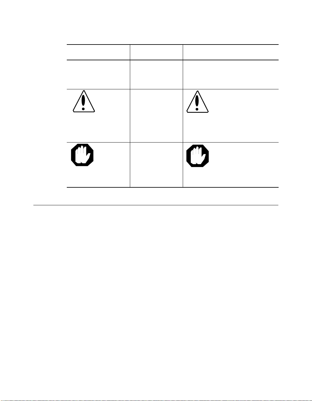
Convention Indicates Example
Note: A Note. The
Caution: A Caution. A
Warning: A Warning. A
Related Docu me nts
This section provides information on supporting documentation, including:
❑ 3Com Documents
information is
important
condition may
damage
software or
hardware
condition may
threaten
personal safety
Note: Use STP lobe
cables for yo ur s yste m.
Caution: Do not put
your installation
diskettes on a
magnetic surface.
This may damage the
diskettes.
Warning: Wear eye
protec tion when
performing these
maintenance
procedures.
❑ Reference Documents
xvi ONline Ethernet 24-Port 10BASE-T Module Installation Guide
Page 17

3Com Documents
The following documents provide ad ditional information on 3Com
products:
17-Slot ONline System Concentrator Installation and Operation
Guide – Explains how to install, operate, and manage the 3Com ONline
17-Slot Syste m Concentra tor (Models 5017C-LS and 5017 C with load
sharing).
6-Slot ONline System Concentrator Installation and Operation
Guide – Explains how to install, operate, and manage the 3Com ONline
6-Slot System Concentrator.
ONline Ethernet Management Module Installation and Operation Guide –
Describes h ow to install the ONline Ethernet Management Module in the
ONline System Concentrator and explains the LEDs on the module
faceplate. This guide also provides instructions for connecting a terminal to
the module and describes the management commands necessary to
perform man ag ement tasks on the concen trator and on remote device s.
ONline Management Commands Guide – Provides an alphabetize d
reference resource describing all ONline ma nagement commands.
For a complete list of 3Com documents, contact your 3Com representative.
Reference Documents
The following documents supply related background information:
Case, J., Fedor, M., Scoffstall, M., and J. Davin, The Simple Network
Management Protocol, RFC 1157, University of Tennessee at Knoxville,
Performan ce Systems International and the MIT Laboratory for Computer
Science, May 1990.
Rose, M., and K. McCloghrie, Structure and Identification of
Management Information for TCP/IP-based Internets, RFC 1155,
Performance Systems International and Hughes LAN Systems, Ma y 1990.
ONline Ethernet 24-Port 10BASE-T Module Installation Guide xvii
Page 18

Page 19

1
This chapter introduces you to the 3Com ONline™ Ethernet 24-Port
10BASE-T Modules (Mode l Numbers 5 124M-TPCL an d 5124M-TP). The
modules are re fe renced throughout this guide as the 24-Port Mo dule.
Introduction
You can install both versions of the 24-Port Module in all 3Com ONline
System Conce ntrator and ONcore
This chapter contains the following sections:
❑ Ethernet 24 -Port 10BASE-T Module Description
❑ Theory of Operation
Ethernet 24-Po rt 10BA SE- T Modu le Desc ript ion
This section describes:
❑ Module Features
❑ Model Number 5124M-TPCL Features
❑ Model Number 5124M-TP Features
®
Switching Hub models.
Introduction 1 - 1
Page 20

The ONline Ethernet 24-Port Module is an IEEE 802.3 repeater module that
complies with the 10BASE-T standard. It connects up to 24 devices (PCs,
terminals, printers, modems) to the ONline System Concentrator.
The 24-Port Module (Model Num ber 5124M -TPCL and Model Number
5124M-TP) is a bank switching module. Bank swit ching is th e assi gnment of
a group of 12 consecutive ports to a single ne twork, or to an isolated
network .
Note: You cannot assign individual ports on the 5124M-TPCL and
the 5124M-TP modules to different networks.
Module Features
The ONline Ethernet 24-Port 10BASE-T Module:
❑ Is an IEEE 802.3 repeater module tha t complies with the 10BASE-T
standard.
❑ Connects up to 24 dev ic es (PCs, terminals, printers, m odems) to the
3Com ONline System Concentra tor or ONcore Switching Hub.
❑ Provides high port density at a low cost per port.
❑ Supports up to 100 meters on 10BASE-T-compliant unshielded twisted
pair (UTP) or shielded twisted pair (STP) wiring.
❑ Features “hot swap” capability so that you can install or remove the
module without having to power d own the conc entrator.
❑ Provides bank-switching capability.
❑ Provides a user-selectable autopartition threshold for flexibility in
dealing with collision-related network sl owdowns.
❑ Allows you to disable Link Integrity so you can connect to equipment
that does not conform to the 10BASE-T standard.
1 - 2 ONline Ethernet 24-Port 10BASE-T Module Installation Guide
Page 21

❑ Is designed with all ports internally crossed over, as required by the
10BASE-T standard. This enables you to connect the 24-Port Module
to a 10BASE-T transceiver w ithout using an external crossover
adapter.
Bank Switching Capability
Bank switching is the assignment of a group of twelve consecutive ports to
a single n etwork, or to an isolated network.
In an unmanaged concentrator you can use DIP switches to:
❑ Assign all module ports to an Ethernet network or to an isolated
network
❑ Assign port groups 1 through 12 or 13 through 24 to different
Ethernet or isolated networks
In a managed concentrator you can use network management commands
to assign the following port “groups” to any of three backplane networks,
or to either of two isolated networks:
❑ Ports 1 through 12
❑ Ports 13 through 24
❑ All ports on the mo dule
Model Number 5124M-TPCL Features
Model Number 5124M-TPCL permits you to connect groups of 12
consecutive 10BASE-T-compliant module ports using:
❑ Two 50-pin Telco connectors (one connector attached to 12 ports)
❑ Two 25-pa ir 10 BA SE- T ca bles or two 12-leg “h ydra” cables ( one cable
per 12 ports)
Introduction 1 - 3
Page 22

Model Number 5124M-TP Features
Model Number 5124M-TP permits you to connect individual
10BASE-T-compliant ports using 24 RJ-45 connectors (one connector per
port). The RJ-45 connectors provide direct connections to 10BASE-T cables
(one cable per connected port).
Theory of Operatio n
ONline E thernet 24-Port 10BASE-T Modules incorpora te repeate rs and
twisted pair transceivers that receive and restore amplitude to incoming
signals. 24 -Port Modul e repeaters restore phase and frequenc y.
Repeated signals:
❑ Synchron ize to the system clock
❑ Enter on the TriChannel® bac kp la ne of the ONline System
Concentrator.
Outgoing signals from the TriChannel backplane are:
❑ Sent directly to transceivers
❑ Transmitted to twisted pair link segments by the transceivers
1 - 4 ONline Ethernet 24-Port 10BASE-T Module Installation Guide
Page 23
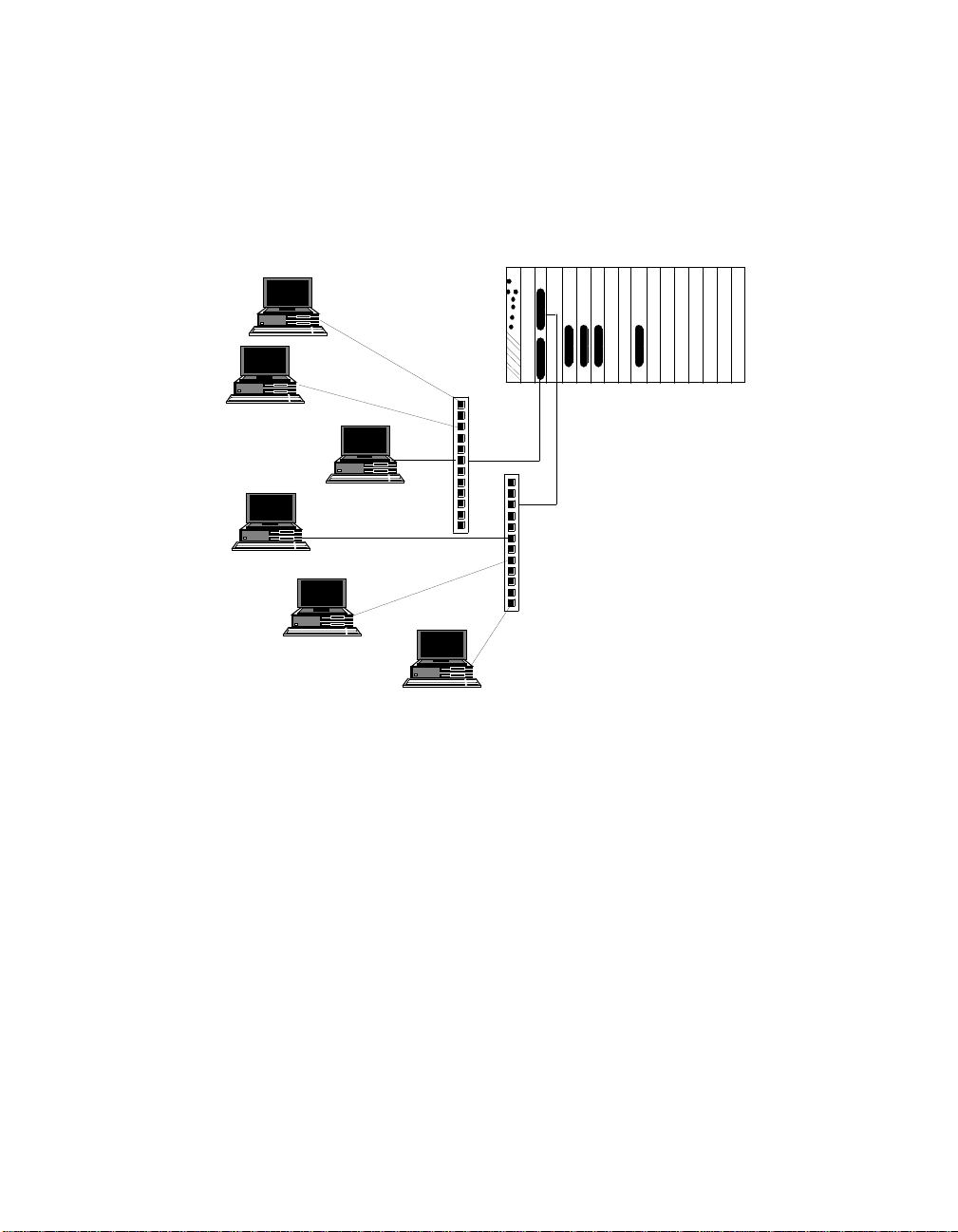
Figure 1-1 shows a 24-Port Module (Model Number 5124M-TPCL) connected
to nodes by means of bundled 25-pair or 12-leg hydra cables and patch
panels.
Concentrator
End Nodes
Patch Panels
Figure 1-1. Typic al 24-Port Module Configuration
Introduction 1 - 5
Page 24

Page 25

2
Designing and
Expanding t he Network
This chapter contains configuration information to help you design your
network . It describes how to configure networks us ing the ONli ne System
Concentrator and ONline Ethernet 24 -Port 10BASE-T Modules. It also
provides examples of network cabli ng structures and Ethernet n etwork
cabling solutions.
This chapter contains the following sections:
❑ Understanding the General Rules
❑ Choosing a Network Backbone Cabling Structure
❑ 24-Port Module Configura tio ns
❑ Using Patch Panels
❑ Establishing Fault-Tolerant Configurations
Note: To ensure proper operation of your network , install all
equipment using only approved cables. Refer to Appendix
A for information on cable requirem ents.
Designing and Expanding the Network 2 - 1
Page 26

Understanding the General Rule s
This section describes general rules for configuring an Ethernet network
using fiber as the backbone medium. It also provides rules to ensure that
your network configuration conforms to distance limitations imposed by
Ethernet and networking equipment. Use these guidelines for building
your network.
Refer to the sections that follow for specific rules for:
❑ Dete rmining maximum 24-Port Module fiber link distances
❑ Connecting various horizontal media types (10BASE-FB, twisted pair)
to a 10BASE-FB backbone
❑ Exampl es of recommended fault-tolerant configurations
This section describes:
❑ Rules for Configuring a Network
❑ Calculating Equivale nt Fiber Dista nces
Rules for Configuring a Network
This section outlines seven basic network rules and 3Com
recommendations for building an Ethernet network.
2 - 2 ONline Ethernet 24-Port 10BASE-T Module Installation Guide
Page 27

For more hardware-specific information on the 24-Port Module, refer to
Appendix A.
Table 2-1. Seven Basic Network Rules
Rule Definition Recommendations/Notes
1 If possible, use
10BASE-FB as the
backbone medium.
2 Wire the backbone in
a star topology to
isolate faults.
3 The maximum Fib er
Ethernet network
diameter is 4200
meters of fiber cable.
Use 62.5 micron cable to conform
with the IEEE 10B ASE-F and
upcoming ANSI FDDI standards.
Use ST-type con n ector s.
Make sure to lay extra fiber
cables. T he extr a cost is sma ll an d
you will find you need them as
your network grows.
The sta r t o po lo gy co nf o rms to
FDDI wiring as well -- just make
sure to run at leas t two fiber
strand s to ever y ba ckbo ne
connection.
The 4200 m ete rs is the ma ximu m
distanc e betw een an y tw o
transceivers on the network.
The 4200 meters does not include
the transceiver cable (that is, drop
or patch cable) that connects a
device wit h an exte rn al
transc eiver. T r ansceiver cables
can extend up to 50 meters. Thus,
total network diameter can be as
much as 4300 meters (4200 m + 2
* 50 m) betwe en any two node s.
Designing and Expanding the Network 2 - 3
Page 28

Table 2-1. Seven Basic Network Rules (Continued)
Rule Definition Recommendations/Notes
4 Certain LAN devices
on the network shrink
the maximum Fiber
Ethernet network
diameter to less than
4200 meters.
5 Assume that one
meter of co axial or
twisted pair is equal to
one meter of fib er
cable.
Many LAN pro du cts de la y th e si gna l
that goes through them. This is
known a s equivalent distance. Ev ery
microsecond delay reduces the
maximum link distance. In fact,
every microsecond delay shrinks the
network diameter by approximately
200 meters of fiber cable. Table 2-2
lists the Equivalent Distances for
other 3Com products.
This is a conservative rule. For
example, the actual equivalence is
about 1.1 meters of coaxial for
every meter of fiber. For simplicity,
assume one meter.
2 - 4 ONline Ethernet 24-Port 10BASE-T Module Installation Guide
Page 29

Table 2-1. Seven Basic Network Rules (Continued)
Rule Definition Recommendations/Notes
6 The f iber l ink dist ances
must not exceed the
limits imposed by the
optical power budget.
7 When in doubt, use a
bridge.
In genera l, on 62. 5 micr on cabl e,
you can go up to 4000 meters
point-to-point using the ONcore or
ONline Fiber Modules. If you have
poor quality cable or cross many
patch panels, you m ay have to
sacrifice some distance.
Some older Ethernet fiber optic
products are les s pow erf ul than
ONcore Fiber Module optics. So
when con nect ing to these
products, remember that the least
powerf ul devi ce det er mines the
maximu m p oin t-t o-p oint dist ance .
If you are not certain if you have
exceeded all owab le netw ork
distances, use a bridge to extend
the network.
Designing and Expanding the Network 2 - 5
Page 30

LAN Equivalence
LAN equivalen ce is the sum of both the incoming and outgoing module
port signals . Different modules, however, have different equivalent
distances. Table 2-2 lists the LAN product equivalent distances.
Table 2-2. LAN Product Equivalent Distances
LAN Product
ONcore Ethernet 10-Port 10BASE-FB Module 190
Incoming signal to fiber port 140
Outgoing signal from fiber port 50
ONcore Ethernet 10BASE-T Module 585
Incoming signal to TP port 420
Outgoing signal from TP port 165
ONline Ethernet 10BASE-T Modules 585
Incoming signal to TP port 420
Outgoing signal from TP port 165
ONline Ethernet Fiber or 10BASE-FB Modules 190
Incoming signal to fiber port 140
Outgoing signal from fiber port 50
ONline Ethernet FOIRL Module 560
Equivalent
Distance (me ters )
Incoming signal to fiber port 330
Outgoing signal from fiber port 230
ONline Ethernet Transceiver Module 0
ORnet Star Coupler (8 or 14 port) 26 180
2 - 6 ONline Ethernet 24-Port 10BASE-T Module Installation Guide
Page 31

Table 2-2. LAN Product Equivalent Distances (Continued)
LAN Product
ONline Ethernet BNC Module 900
Incom ing signal to BNC port 450
Outgoing signal from BNC port 450
ONline Ethernet Repeater Module 800
Incoming signal to AUI port 600
Outgoing signal from AUI port 200
IEEE Repeater 800
Equivalent
Distance (me ters )
Choosing a Netw ork Backbone Cabling Stru cture
Because of fiber's long-distance capabilities and immunity to noise, 3Com
strongly reco mmends using fiber as the backbone.
This section describes:
❑ Building a Netw ork (Star Configuration)
❑ Building a Network (Serial Configuration)
You can implement either of these configuration topologies when
connecting your network backbone using 10BASE-FB modules installed in
an ONline System Concentrator.
Designing and Expanding the Network 2 - 7
Page 32

Building a Network (Star Configuration)
Wire your network in a s tar configuration using an ONline System
Concentrator as the central point in the network. Wiring in a star
configuratio n provides two major ben efits:
❑ Faults in the cable plant affect only a piece o f the network.
❑ You can easily expand the size of your network.
Figure 2-1 shows 10BASE-T and 10BASE-FB modules installed in a star-wired
network.
Figure 2-1. Star-Wiring Configuration
2 - 8 ONline Ethernet 24-Port 10BASE-T Module Installation Guide
Page 33

Building a Network (Serial Configuration)
Use a serial configuration for smal ler diameter networks that are not
expected to grow. Serial configurations reduce the overall network
diameter by 190 meters for each concentrator in any path.
Figure 2-2 shows 10BASE-FB modules installed in a network using a serial
configurat ion.
Figure 2-2. Serial Configuration
Designing and Expanding the Network 2 - 9
Page 34

24-Port Module Configurations
This section describes how to define total network size based on the limits
of IEEE 802.3 collision detection. This section al so describes how to
construct a network consisting of a Fiber Backbone and 10BASE-T
unshielded twisted pair connections to-the-desk.
This section describes:
❑ Fiber Backbone, 1 0BASE-T To-The-Desk
❑ 10BASE-T Backbone, 10BASE-T To-The-Desk
Fiber Backbone, 10BASE-T To-The-Desk
Be aware of the following additional rules for configuring a network:
❑ The four-repeater rule in Ethernet limits the number of 10BASE-T
modules between any two transceivers. The path from the TP port to
the backplane counts as 1/2 of a repeater and the path from the
backplane to the TP port counts as 1/2 of a repeater. You must add
a bridge if the path from one transceiver to an other exceeds the
four-repeater rule.
❑ The equivalent fiber distance for 10BASE-T modules is defined as
follows:
– 420 meters for signals that external ly enter a 10BASE-T
module port
– 165 meters for signals that internally enter a 10BASE-T
module through the ONline concentrator backplane
For each pair of 10BASE-T modules that a signal goes through, there is an
equivalent fiber distance of 585 meters (420 m + 165 m =585 m). In
addition, if a signal makes a roundtrip through a 10BASE-T Module (that is,
enters a 10BASE-T port externally and e xits through another port on the
same 10BASE-T module), that counts as 585 meters of equivalent fiber
distance, and as a full repeater.
2 - 10 ONline Ethernet 24-Port 10BASE-T Module Installation Guide
Page 35

Example: Sample Configuration Distance Calculation
Use the following example to determine if the 10BASE-T transceivers in
Figure 2-3 are within legal Etherne t limits. Identify the two transceiv ers
that are likely to be the greatest fiber equivalent distance apart. In
Figure 2-3, they are 10BASE -T transceivers A and B.
Figure 2-3 shows 24-Port Modules installed in each of three concentrators.
Figure 2-3. Sample Configuration Distance Calculation Using
24-Port Modules
To determine if your network configuration is legal:
1. Use 4200 m as the maximum network diameter for a pure fiber
network as defined by the 802.3 specification.
Designing and Expanding the Network 2 - 11
Page 36

2. Calculate the equivalent distances for each concentrator, and
subtract the total from 4200.
3. Subtract all cable lengths betw een the two transceivers and if the
result is greater than zero, the configuration is within legal Ethernet
limits.
For the con figuration shown in Figure 2- 3 to work, ensure the equivalent
fiber distance between Transceiver A and Transceiver B is less than 4200
meters.
As shown in the calculation, there are still 1510 meters left for expansion in
this confi guration. Therefore, this configuration is legal.
10BASE-T Backbone, 10BASE-T To-The-Desk
In constructing a twisted pair backbone:
❑ Ensure there are no more than eight 10BASE-T modules in the path
between any two transceivers (Ethernet four-repeater rule). Each
10BASE-T module counts as 1/2 of a repeater unless th e s ignal go es
in one port and out another port on the same module. In that case,
the module counts as a full repeater.
❑ Add a bridge if you have more than eight 10BASE-T modules serially
connected. Each bridge creates a subnetwork. Each subnetwork can
have its own 4200 meter network diameter.
Figure 2-4 shows a possible unshielded twisted pair network using 24-Port
Modules and 24-gauge cable.
2 - 12 ONline Ethernet 24-Port 10BASE-T Module Installation Guide
Page 37

Figure 2-4. Unshielded Twisted Pair Network Using 24-Port Modules
The equivalent fib er distance can be calculated as follows:
Total link distance: 100 m + 100 m + 100 m + 50 m + 20 m = 370 m
Total equivalent distance of the 24-Port Modules:
4*420m+4*165m=2340 m
(signal externally enters 4 Twisted Pair Modules: 4 * 420 m)
(signal internally enters4 Twisted Pair Modules from the backplane: 4 *
165 m)
Note: All 3Com 10BASE-T modules (8-Port 10BASE-T Mo dule,
50-Pin 10BASE-T Module, or the 24-Port 10BASE-T Modules)
fall unde r these same rules.
Total equivalent distance: 370 m + 2340 m = 2710 m
Because the total equivalent distance (2710 m) is less than 4200 meters, this
configuration is legal.
Designing and Expanding the Network 2 - 13
Page 38

Using Patch Pane ls
Patch panels weaken signals that pass through them, thereby reducing
achievable link distances. 3Com assumes the use of one patch panel in the
100 meter link distance calculations specified in this installation guide. Each
additional patch panel in the link reduce s the 100 meter link distance by
approximately 10 meters.
In Figure 2-4:
❑ If two patch panels were used between the top right PC and the top
right concentrator, the link distance of 100 meters would have to be
shortened to 90 meters.
❑ The link distance would have to be shortened to 90 meters because
the maximum allowable link distance on 24-gauge wire using
10BASE-T signaling with two intervening patch panels is 100 meters
minus approximately 10 meters.
❑ A patch panel installed between the bottom right PC and the bottom
left concentrator would not affect the link because it is only 20
meters away.
Establishing Fault-Tolerant C onfig u rations
You can establish fault tolerance for any port on the 24-Port Module, for
selected portions of the network ba ck bone, or for the entire network
backbone.
This section describes:
❑ Setting Port Redundancy
❑ Setting Backbone Redundancy
2 - 14 ONline Ethernet 24-Port 10BASE-T Module Installation Guide
Page 39

Setting Port Redundancy
When you enable redundancy between two ports, the ports are
automatically enabled. Once port redundancy is enabled:
❑ Port 1 is the primary link, which passes data.
❑ Port 2 is the redundant link, which does not pass data in either
direction. However, the link is monitored for any failures (the Port
Status LED indicates any problems).
Configuring Ports for Fault Tolerance
You can configure the 24-Port Module ports in one of three different ways:
❑ Norma l Co nfiguration - All ports operate as independent cable
ports.
❑ Flexible Redundant Co nfiguration - You can a rbitrarily assign
primary and backup ports to any pair of ports. You can configure
this mode only through the advanced management commands
provided with the Ethernet Management Module Version v3.0 or
later.
❑ Norma l a nd R edundant Configuratio n - You can enable
redund ancy between one set of ports and have the remaining ports
operate as independent ports.
Setting Backbone Redundancy
For maximum backbone tolerance, connect both the primary and backup
ports back to the central co ncentrator (refer to Figure 2-5). This
configuration allows the backup port to automatically take over if the
primary link fails.
Designing and Expanding the Network 2 - 15
Page 40

Redundant Twisted Pair Backbone
You can implement twisted pair link redundancy between ONli ne System
Concentrators using network management.
Figure 2-5 shows an example of a redundant configuration between
concentrators using 24 -Port Modules.
Figure 2-5. Redundant Twisted Pair Configuration Using 24-Port
Modules
To set link redundancy between two 24-Port Modules (refer to Figure 2-5):
1. Connect one port on the 24-Port Module installed in the concentrator
on the left to a corresponding port on the 24-Port Module installed in
the concen trator on the right.
2. Connect the s econd port on the 24-Port Module installed in the
concentrator on the left to a corre sponding port on the 24-Port
Module installed in the co ncentrator on the right.
Note: Use a crossover adapter between each link becau se the
links are de signed to b e connected to station ports, not to
other lobe ports.
2 - 16 ONline Ethernet 24-Port 10BASE-T Module Installation Guide
Page 41

3. Use the SET PORT MODE REDUNDANT network management
command to specify which port is the primary link and which is the
backup link.
Note: If the 24-Port Modules are powered down, and then
brought back up without a 3Com network management
module presen t, a network l oop may occur. To preve nt
possibe network failure, set the DIP switch for the backup
port to disable.
Once redundancy is configured, a switchover occurs under two conditions:
❑ Link fai lure
❑ Port partition
The switchover occurs when the primary link fails.
A switchover back to the primary link happ ens automatically once the
problem is resolved.
Refer to the appropriate network management module installation and
operation guide for information on setting redundancy between 24-Port
Module ports.
Designing and Expanding the Network 2 - 17
Page 42

Page 43

3
This chapter describes installation procedures for the ONline Ethernet
24-Port 10BASE-T Modules (Model Number 5124M-TPCL and Model Number
5124M-TP).
This chapter contains the following sections:
Installing and Operating the Module
❑ Precautionary Procedures
❑ Quick Installation
❑ Unpacking Procedure s
❑ Setting the DIP Switches
❑ Installing the Module
❑ Config uration in a Managed Env ironment
❑ Saving Module Configurations
❑ Showing Module Confi g urations
❑ Gathering Network Statistics
❑ Monitoring the Front Panel
❑ Verifying LED and Network Assignments
Installing and Operating the Module 3 - 1
Page 44

Precautionary Procedures
Electrostatic discharge (ESD) can damage static-sensitive device s on circuit
boards. Follow these precautions when you handle the 24-Port Mo dule.
❑ Do no t remove the board from its antistatic shielding bag until you
are ready to inspect or insta ll it.
❑ Handle the board by the faceplate only.
❑ Use proper grounding techniques when you install the 24-Port
Module. These techniques include:
– Using a foot strap and grounded mat o r wearing a
grounded static discharge wrist strap.
– Touching the grounded rack or other sou rce of ground
just before you handle a 24-Port Module.
Quick Inst allation
Table3-1 outlines the steps for installing your module. If you are familiar
with installing ONline modules, you may want to use this table as a
checklist. Otherwise , consult the remain der of this chapter.
Table 3-1. Procedures for Completing Installation
Step Procedure Section Title
1 Verify that your network complies
with the basic rules for network
design.
2 Unpack the module. Chapter 3, Unpacking
3 - 2 ONline Ethernet 24-Port 10BASE-T Module Installation Guide
Chapter 2, Designing
and Expanding the
Network
Procedures section
Page 45

Table 3-1. Procedures for Completing Installation
Step Procedure Section Title
3 If you do not have a management
module installed in the concentrator,
configure the DIP switch settings to
your specifica t ion s.
4 If you have Model Number
5124M-TPCL, insert the module into a
single open slot in the concen trator
and tighten the faceplate screws.
If you have Model Number 5124M-TP,
insert the module into two
consecutive empty slots in the
concentrator and tighten the faceplate
screws.
5 Est abl ish conn ect ion s fr om the 24- Port
Modul e to devices or to a 10BASE- T
transceiver using the appropriate
connectors and cabling.
6 If you have a management module
installed in the concentrator, configure
the module using the management
commands.
Chapter 3, Setting the
DIP Switches section
Chapter 3, Installing
the Module section
Chapter 3, Installing
the Module section
Chapter 3,
Configuring the
Module section
7 Verify LED status for normal
operation.
Note: To correct problems, consult
the troubleshooting techniques in
Chapter 4.
Installing and Operating the Module 3 - 3
Chapter 3, Verifying
LED and Network
Assig nments section
Page 46

Unpacking Procedu res
When unpacking your 24-Port Module:
1. Verify that the 24-Port Module is the model you ordered by checking
the model number listed on the side of the shipping carton (Model
Number 5124M-TPCL or Model Number 5124M-TP).
Note that the p roduct mod el number printed on the shipping box
differs from the model number on the pro duct. The m odel number
on the shipping box contains the prefix ’3C9’.
2. Remove the module from the shipping carton.
3. Remove the module from the antistatic shiel ding bag and inspect it
for damage. If the module appears to be damaged, replace it in the
antistatic shielding bag, return it to the s hipping carton, and co ntact
your local supplier.
4. Keep the shipping carton and antistatic shielding bag in which your
module was shipped for repackaging the module for storage or
shipment.
5. Record the serial number of your 24-Port Module. A log for this and
other information specific to your modules is included in the ONline
System Concentrator Installation and Operation Guide, Appe ndix B,
Slot Usage Chart.
Setting the DIP Swit c hes
This section describes:
❑ DIP Switch Overview
❑ DIP Switch Description
3 - 4 ONline Ethernet 24-Port 10BASE-T Module Installation Guide
Page 47

DIP Switch Overview
The 24-Port Module has a single switch located on the module. This switch
contains 10 DIP switches that let you:
❑ Assign 12-ports o n each 50-pin connector to a network (Model
Number 5124M-TPCL)
❑ Assign 12 ports on each Double Stack RJ-45 connector to a
network(Model 5124M-TP)
❑ Enable or disable all ports on each connector
❑ Establish Link Integrity for each connector (or group of 12 po rts)
❑ Isolate all ports on one connector (or group of 12 ports)
❑ Isolate all ports on both connectors. This setting isolates the module
from the backplane.
Note: All DIP switch settings on the 24-Port Module are ignored if
an ONline management module (EMM Version v3.2 or later
[for Model Number 5124M-TPCL] EMM Version v4.3 or later
[for Model Numbner 5124M-TP]) is already installed in the
concentrator. 3Com recommends that you use network
management commands to configure the module instead
of the DIP switches. To override management and
configure the module to DIP switch settings in a managed
hub, enter the SET DEVICE DIP_CONFIGURATION
command.
Installing and Operating the Module 3 - 5
Page 48

Figure 3-1 shows the location of the DIP sw itch component on the 24-Port
Module.
Figure 3-1. Model 5124M-TPCL and Model 5124M-TP DIP Switch
Location
3 - 6 ONline Ethernet 24-Port 10BASE-T Module Installation Guide
Page 49

DIP Switch Description
DIP switches are labeled 1 through 10 (refer to Figure 3-1). DIP switches 1
through 4 enable features for con nec tor 1 (CONN 1). DIP switches 5
through 8 enable features for connector 2 (CONN 2). DIP switch 9 isolates
all ports (both connectors) from the backplane, or 12 ports on either
connector. Modules or ports set to the same network communicate with
each other.
Note: The DIP switch label on the module circuit board refers to
the backplane connection a s “channel” (CH). Thi s is the
“network ” s etting.
Installing and Operating the Module 3 - 7
Page 50

Tables 3-2 and 3-3 describe DIP switch settings. For a complete definition
of each DIP switch function, refer to the section Configuring the Module
later in this chapter.
Table 3-2. DIP Switch Settings
DIP
Switch
1
2
3 PORT EN Enable/Dis ableC
4 LI EN Enable/Disable
5
6
7 PORT EN Enable/Dis able
8 LI EN Enable/Disable
Label Function
CH SEL0
CHSEL1
CH SEL 0
CH SEL 1
Select
Connector 1
Network
onnector 1 Ports
Connector 1
Link Integrity
Select
Connector 2
Network
Connector 2
Ports
Connector 2
Link Integrity
Factory
Default
See Table 3-3.
Enable Disable Enable
Enable Disable Enable
See Table 3-3.
Enable Disable Enable
Enable Disable Enable
DIP Switch Setting
Off On
9 ISO SEP Isolate
One/Both
Connectors
10 Not
Used
3 - 8 ONline Ethernet 24-Port 10BASE-T Module Installation Guide
None
One Both One
Page 51

The chann el select s witch setting s (switches 1 and 2 for connector 1, and
switches 5 and 6 for connector 2) let you selec t a channel for each
connector. To reconfigure the module to a different channel, refer to the
information in Ta ble 3-3.
Table 3-3. Channel (Network) Select DIP Switch Settings
DIP Switch
Setting (CONN 1 )
DIP Switch
Setting (CONN 2)
Switch 1 Switch 2 Switch 5 Switch 6 Network Selection
On On On On 1 (default)
Off On Off On 2
On Off On Off 3
Off Off Off Off Isolated (connector
operates independent
of the three backplane
networks)
Installing and Operating the Module 3 - 9
Page 52

Installing the Module
You do not need to power down the ONline System Concentrator to install
the 24-Port Module. You can insert the module while the concentrator is
operating (this is called a hot swap).
To install a 24-Port Module:
1. Depending on whether or not you have a management module
installed in the hub, follow one of the steps below:
❑ If network management is not available, set the DIP switches on
the board (if different than the default values). Refer to Table 3-2
and Table 3-3 for an explanation of the DIP switch settings.
❑ If a network management module is installed in your
concentrator:
– If your management module is not EMM Version v4.3 or
later (for Model Number 5124M-TP) or EMM Version v3.2
or later (for Model Number 5 124M-TPCL), it does not
support the particular 24-Port Module. Enter the SET
DEVICE DIP_CONFIGURATION command to configure the
24-Port Module from DIP switch settings.
– If your management module is at the appropriate
software level, go to step 2 and complete the installation,
then config ure the 24-Port Module using the commands
described in the Configuring the Module section.
2. For Model Number 5124M-TPCL, locate one open slot in the
concentrator. Remove the blank panel on the concentrator to expose
a slot for the module.
For Model Number 5124M-TP, locate two adjacent open slots in the
concentrator. If there are no adjacent open slots, remove two
adjacent blank panels on the concentrator to exp ose the slots you
need to i nstall the module.
3 - 10 ONline Ethernet 24-Port 10BASE-T Module Installation Guide
Page 53

3. Insert the module into the board guides at the top and bottom of the
selected slot and slide the board into the concentrator. Make sure
the connector is well-seated into the backplane of the concentrator.
Figure 3-2 shows the installation of a 24-Port Module.
Figure 3-2. Installing a 24-Port Module (Model Number 5124M-TPCL)
4. Fasten th e spring-loaded screws on the front of the 2 4-Port Module
faceplate to the concentrator with your fingers (do not overtighten).
5. For the 5124M-TPCL model only, use the small screws included in the
shipping carton and attach 180° 50-pin cable connectors to the
50-pin connectors on the front of the module (refer to Figure 3-3) .
Note: If you are usin g 90° connectors, refer to the special
instructions provided in the section Using 90° Cable
Connectors.
Inst alling an d Operatin g the Modul e 3 - 11
Page 54

6. If you have installed Model Number 5124M-TPCL, attach and secure
cable connectors to module connectors as shown in Figure 3-3.
Figure 3-3. 24-Port Module Cable Co nnection
(Model Number 5124M-TPCL)
7. Attach the other ends of the cables to any of the following:
❑ A 10BASE-T transc eiver
❑ A patch panel
❑ A 10BASE-T adapter card
3 - 12 ONline Ethernet 24-Port 10BASE-T Module Installation Guide
Page 55

Using 90° Cable Connectors
3Com recom mends that you use 180° connectors with the 5124M-TPCL
model. Because of the proximity of the two connectors, you must follow
the special steps described below if y ou decide to use 90° (right-angle)
connectors.
This section describes:
❑ Installing the Cabl e Ti e-W rap Kit
❑ Securing 90° Cables to the Module
Installing the Cable Tie-Wrap Kit
A cable tie-wrap kit is included with the 24-Port Module. If you use a cable
connector other than a 180° cable connector (for example, a 90° cable
connector), you must secure the cable to the module connector using the
tie-wrap kit.
The tie-wrap kit contains:
❑ Kit card containing kit part number
❑ 1 Phillips-head screw
❑ 1 Tie-wrap bracket
❑ 3 Tie-wraps
To install the tie-wrap kit:
1. Remove the hex nut from the bo ttom of the connector located on
the module faceplate.
2. Using the Phillips-head screw provided in the tie-wrap kit, attach the
tie-wrap bracket to the m odule (Figure 3-4).
Inst alling an d Operatin g the Modul e 3 - 13
Page 56

Figure 3-4. Attaching the Tie-Wrap Bracket to the Module
3. Insert the tie-wrap through the opening on the tie-wrap brac ket.
3 - 14 ONline Ethernet 24-Port 10BASE-T Module Installation Guide
Page 57

Securing 90° Cables to the Module
To secure 90° cables to the 24-Port Module connectors:
1. Remove the small cable-fastening screws from the shipping carton.
2. Remove the long screws (if present) from the 50-pin cables.
3. Attach a 50-pin cable connector to one of the 50-pin connectors on
the front of the module (see Figure 3-5).
Figure 3-5. Attaching Cables With 90° Connectors
(Model Number 5124M-TPCL)
Note: Due to the proximity of the top and bottom 50-pin
connectors, you must install a standoff if you intend to use
a right-angle connector on the top connection. Contact
your 3Com representative if you need more information.
Inst alling an d Operatin g the Modul e 3 - 15
Page 58

4. Replace the small screw in the top screw hole of the 50-pin cable
connectors to secure the cables to the module connectors as shown
in Figure 3-5.
Note: Do not overtighten the top screw on either conn ector.
Over tightening the top screw can cause the bottom part
of the connector to lift and disconnect the lower pins on
the cable from the lower pins on the module connector.
5. Wrap the tie-wrap around the cable connector to secure the cable
connector to the module connector (see Figure 3-6). Do not fasten
the tie-wrap around the module ejectors.
Figure 3-6. Attaching Cables With 90° Connectors
3 - 16 ONline Ethernet 24-Port 10BASE-T Module Installation Guide
Page 59

6. Attach the other ends of the cables to any of the following:
❑ A 10BASE-T transc eiver
❑ A patch panel
❑ A 10BASE-T adapter card
Configuration in a Managed Environment
With an EMM already installed, all DIP switch settings on the 24-Port
Module are ignored. For this reason, 3Com recommends that you use
network management commands instead of DIP switches to configure the
module.
Note: Do not use a sl av e management module to manage (for
example, c onfigure or get statisti cs for) a 24-Port Module.
Note: To fully support Model Number 5124M-TPCL, you must have
EMM Version v3.2 or later. To fully support Model Number
5124M-TP, y ou must have EMM Version v4.30 or later.
The following sections describe important module configuration issues and
settings you can configure for both models of the 24-Port Module:
❑ If Management is Not Available
❑ Before Configuring the M odule
❑ Enabling Ports
❑ Enabling Port Redundancy
❑ Enabling Link Integrity
❑ Selecting a Netwo rk
Inst alling an d Operatin g the Modul e 3 - 17
Page 60

❑ Enabling Remote Diagnostics Mode
❑ Setting the Autopartition Threshold Value
For additional information on any network managem ent command
described in this section, refer to the appropriate ONline Management
Module Installation and Operation Guide.
If Management is Not Available
When you first install the 24-Port Module in an unmanaged concentrator,
configure the 24-Port Module using the DIP switches as described in the
section Setting the DIP Switches. For additional information on all network
management fea tures, refer to:
❑ The appropriate ONline Management Module Installation and
Operation Guide, or the ONcore Distributed Management Module
User 's Guide
❑ The ONline Management Commands Guide or the ONcore
Distributed Management Module Commands Guide
Note: The 24-Port Module, Model Number 5124M-TP, is a 2-slot
module that has a double-wide faceplate but only one
circuit boa rd. The slot number of the circuit board
determine s the slot number of an installed 5124M-TP
module.
3 - 18 ONline Ethernet 24-Port 10BASE-T Module Installation Guide
Page 61

Before Configuring the Module
When you first install the 24-Port Mo dule in a managed conce ntrator:
1. The network (channel) defaults to isolated mode an d all ports are
automatically disabled so unapproved stations cannot be added.
Therefore, you mu st use manag ement commands to:
– Enable ports you want to use
– Assign enabled ports to backplane networks
2. All other module settings retain DIP switch default values.
Enabling Ports
You can enable or disable each of the ports on the 24-Port Module. When
a port is enabled, it can transmit to and re ceive data from the network
(channel) that the module or connector (bank) is assigne d to.
To enable a port, use the following network management command:
SET PORT {
slot.port
{
slot
} MO DE {enable}
.all} {disable}
Enabling Port Redundancy
Network management lets you set redundancy between ports. When you
set two ports redundant to each other, the secondary port takes over if the
primary port fails.
To set redundancy between ports, use the following management
command:
SET PORT {
Refer to Chapter 2 for an example of port redundancy.
slot.port
} MODE {redundant} {
{non-redundant}
Inst alling an d Operatin g the Modul e 3 - 19
slot.port
}
Page 62

Enabling Link Integrity
Use the following guidelines to determine whether to enable or disable
Link Integrity:
❑ Enable Link Integrity for all ports on the 24-Port Module for networks
that comply with the 10BASE-T standard.
❑ Disable Link Integrity only when connecting to older equipment that
does not comply with the 10BASE-T standard.
The Link Integrity setting at both ends of a connection must be either
enabled or disabled. If Link Integrity settings are not configured to the
same setting, the 24-Port Module with Link Integrity enabled reports a Link
Integrity error.
The Link Status LED for each connector (bank) will be on s olid if the Link
Integrit y is valid for ports which are both enabled and have Link Integrity
enabled. If all enabled ports have Link Integrity testing disabled the LED is
also on solid. In all other cases the LED will blink in approximately 1-second
intervals.
Note: In an unmanaged concentrator, you can only enable or
disable Link Integrity for e ach connector on the module.
To enable Link Integrity for a port:
SET PORT {
slot.port
{
slot.
all} {disable}
} LINK_INTEGRITY {enable}
Selecting a Network
The ONline Ethernet 24-Port Module provides bank-level configuration
flexibility.
To assign all 24 ports on the module to one of three backplane networks,
use the following management command:
3 - 20 ONline Ethernet 24-Port 10BASE-T Module Installation Guide
Page 63

SET MODULE {
slot
} NETWOR K {ethernet_1}
{ethernet_2}
{ethernet_3}
{isolated}
To assign a specific connector (bank of 12 ports) to a network, use the
following management command:
SET MODULE {
slot
} CONNECTOR_{1}_NETWORK {ethernet_1}
{2} {ethernet_2}
Note: Assigning one connector to ISOLATED_1 and the ot her
connector to ISOLATED_2 creates two isolated 12-port
subnetworks. Assigning both connectors to the same
isolated network creates a single 24-port isolated network.
Enabling Remote Diagnostics Mode
When used with a 3Com Fault-Tolerant 10 BASE-T Transceiver, rem ote
diagnostics mode allows the 24-Port Mo dule to dete ct certain unusual
failure conditions (including disruption of single wires in the twisted pairs).
{ethernet_3}
{isolated_1}
{isolated_2}
Refer to the Fault-Tolerant 10BASE-T Transceiver Installation Guide for
more information on this feature.
To enable remote diagnostics mode for a specific port, use the following
management command:
SET PORT {
slot.port
} MODE {remote_diagnostics} {
{non_remote_diagnostics}
slot.port
Inst alling an d Operatin g the Modul e 3 - 21
}
Page 64

Setting the Autopart ition Threshold Value
To set the maximum number of data collisions an installed management
module allo ws on a port before it partitions the port, use the following
management command:
SET MODULE {slot} AUTOPARTITION_THRESHOLD {31_coll}
You can set the autopartition threshold value to one of the following:
❑ 31
❑ 63 (default value)
❑ 127
❑ 255
The proper setting for most network environments is 63 (the default). The
10BASE-T specification suggests a minimum autopartition threshold value
of 31, but 31 collisions may cause ports to partition more frequently than
necessary.
{63_coll}
{127_coll}
{255_coll}
Note: Autopartition values 127 and 255 are suggested only for
debugging purposes, and are not recommended for use in
live networks.
3 - 22 ONline Ethernet 24-Port 10BASE-T Module Installation Guide
Page 65

Saving Module Configurations
After you make configura tion changes to a module and ports, you must
issue the SAVE MODULE_PORT command to save the new settings.
Showing Modu le Conf ig urat ions
You can display status information about the 24-Port Module using the
following network management commands:
❑ SHOW MODULE
❑ SHOW PORT
This section describes these commands. Screen output examples are also
provided.
For more information, refer to the ONline Ethernet Management Module
Installation and Operation Guide.
Note: When the command argument NO_VERBOSE is an option,
you do not have to type NO_VERBOSE, NO_VERBOSE is the
default.
Inst alling an d Operatin g the Modul e 3 - 23
Page 66

Show Module
To display information for a module in a specific slot, use the following
management command:
SHOW MODULE {
To display basic information ab out a 24-Po rt Module installed in slot 3,
specify the NO_VERBOSE command argument, as shown below:
ONline> show module 3 [ENTER]
Slot
03 5124M-TPCL 001 ETHERNET_2 Port (s) are down
Note: The NO_VERBO SE command argument is the default (you
To display detailed information about an installed 24-Port Module, specify
the verbose command argument, as shown below:
ONline> show module 3 verbose [ENTER]
Slot
03 5124M-TPCL 001 ETHERNET_2 Port (s) are down
slot
} {no_verbose}
{verbose}
Module Version Network General Informa tion
do not have to enter it at the prom pt).
Module Version Network General Information
5124M-TPCL: ONline Ethernet 24-PORT 10BASE- T Module
Auto-Partition Threshold : 255 COLLISIONS
Module Per Port Counters : CONNECTOR 1
Network for Connector 01 : ETHERNET_2
Network for Connector 02 : ETHERNET_2
Dip Network Setting for Connector 01 : ETHERNET_1
Dip Network Setting for Connector 02 : ISOLATED_1
3 - 24 ONline Ethernet 24-Port 10BASE-T Module Installation Guide
Page 67

Show Port
To display information for a s pecific port, use the following management
command:
To display basic information for a speci fic port, spec ify the NO_VERBOSE
command argument. To display basic information for all ports on the
24-Port Module, specify the ALL command argument.
Note: The NO_VERBO SE command argument is the default (you
In the following example, SHOW PORT ALL displays basic information for all
ports on the 24-Port Module installed in slot 5:
SHOW PORT {
{
slot.port
slot
} {no_verbose }
.all} {verbos e}
do not have to enter it at the prom pt).
ONline> show port 5.all [ENTER]
Port Display for Module 5124M-TPCL :
Port Mode Status Network General Information
————— ———— —————— ——————— ———————————————————
05.01 DISABLED OKAY ISOLATED
05.02 ENABLED OKAY ISOLATED
05.03 ENABLED OKAY ISOLATED
05.04 DISABLED OKAY ISOLATED
.
.
.
Inst alling an d Operatin g the Modul e 3 - 25
Page 68

To display detailed information for all po rts on the 24-Port Module, specify
the VERBOSE command argument. In the following example, SHOW PORT
ALL VERBOSE displays detailed information for all ports on the 24-Port
Module instal led in slot 17 (only the o utput for ports 1 and 2 is shown):
ONline> show port 17.all verbose [ENTER]
Port Display for Module 5124M-TPCL :
Port Mode Status Network General Information
————— ———— —————— ——————— ———————————————————
17.01 DISABLED OKAY ISOLATED
Port Connector: TELCO
Mode Dip Setting: ENABLED
Link Integrity: ENABLED
Link Integrity Dip Setting: ENABLED
17.02 DISABLED OKAY ISOLATED
Port Connector: TELCO
Mode Dip Setting: ENABLED
Link Integrity: ENABLED
Link Integrity Dip Setting: ENABLED
.
.
.
3 - 26 ONline Ethernet 24-Port 10BASE-T Module Installation Guide
Page 69

Gathering Network Statistics
When you assign all po rts on the 24-Port Module to the same network, an
installed management module can simultaneously monitor all ports on one
connector individually as it monitors the ports on the other connector
collectively.
For example, you can use an ins talled EM M or Distributed Management
Module (DMM) to simultaneously:
❑ Monito r ports 1 through 12 individually
❑ Sum up statistics for ports 13 through 24 at a single “lo gical port”
(port 13)
Gathering statistic s for individual ports on one connector enables network
management to provide a d etailed statistical view of each p ort on that
connector. Collective statisti cs gathering for all po rts on the other
connector ensures you have at least a high-level statistical view of ports on
that connector.
An ONline management command lets you switch to monitor the other
connector. The follow ing section desc ribes the SET MODULE command.
Inst alling an d Operatin g the Modul e 3 - 27
Page 70

Selecting the Per-Port Counters Connector
When you select a connector, network management monitors the other
connector collectively, reporting statistics for all 12 ports as a single “po rt.”
To select which 12-port con nector you want network management to
gather counter statistics for:
SET MODULE {
{2}
If you ask for information on a port that is not being monitored individually,
network management displays summary statistics and instructions for
getting m ore information on the selected port.
Note: The MONITOR PORT a nd SHOW COUNTER PORT
commands will functio n normally for the connector you
have selected.
Note: Changing which connector you are monitoring clears all
statistics counters. Use the CLEAR COUNTERS command to
erase extraneous statistics gathered during the switchover
from one c onnector to the other co nnector .
slot
} PER_PORT_CO UNTERS _CONNEC TO R {1}
3 - 28 ONline Ethernet 24-Port 10BASE-T Module Installation Guide
Page 71

Monitoring the Front Panel
The LEDs on the front panel of the 24-Port Module allow you to monitor
the status of 12 ports on each connector. The 24-Port Module has an
Activity LE D and a Status LED for each c onnector.
Figure 3-7 shows the location of the LEDs on Model Number 5124M-TPCL.
Figure 3-7. 24-Port Module Faceplate and ONline System
Concentrator (Model Number 5124M-TPCL)
Inst alling an d Operatin g the Modul e 3 - 29
Page 72

Figure 3-8 shows the location of the LEDs on Model Number 5124M -TP.
Figure 3-8. 24-Port Module Faceplate and ONline System
Concentrator (Model Number 5124M-TP)
3 - 30 ONline Ethernet 24-Port 10BASE-T Module Installation Guide
Page 73

Table 3-4 describes the LEDs for Model Numbers 5124M-TPCL and 5124M-TP.
Table 3-4. 24-Port Module LED Interpretations
LED Name Color State Indica tes
Activity
(Ports 1 to 12)
(Ports 13 to
24)
Status
(Ports 1 to 12)
(Ports 13 to
24)
Yellow Off No packets are received on the
ports on this connector.
On Constant activity on this
connector.
Blinking Normal activity on this
connector.
Green On Connector enab led and links OK
or Link Integrity disabled.
1 blink Link failure on one or more
ports.
2 blinks One or more ports partitioned.
Off Connector disabled.
Inst alling an d Operatin g the Modul e 3 - 31
Page 74

Verifying L ED and Netw ork As signme nt s
Once you install the 24-Port Module, verify module operation u sing the
front panel of the ONline Controller Module.
Using the LED Check Button
The ONline Controller Module is equipped with an LED check button on the
front panel. Use the LED check button to:
❑ Verify L E D operation
❑ Verify network (channel) assignment
The LED check button:
❑ Causes all LEDs in all modules in the concentrator to light
❑ Causes each installed module to identify the network to which it is
assigned
When you pre ss the LED check button, the Controller Module initiates a
test of all m odules in the concentrator.
❑ All LEDs should respond by lighting continuously for approximately 5
seconds.
❑ Any LED tha t does not light is defective.
After 5 sec onds elapse, the diagnostic continues with a network (channel)
check of all installed modules.
❑ Port Status LEDs on each installed module should blink the number of
times corresponding to the network to which that module (or
connector) is assigned.
3 - 32 ONline Ethernet 24-Port 10BASE-T Module Installation Guide
Page 75

❑ If the module is in isolated mode, the Port Status LEDs on that
module (or connector) do not light.
❑ Acti vity LEDs rema in on during the network check sequence.
The network check sequence repeats at least three times, and eac h check
sequence lasts for approximately 30 seconds.
Table 3-5 explains the net work check codes.
Table 3-5. Network Check Codes
LED State Network Configuration
1 Blink Connecto r is configured for network 1
2 Blinks Connecto r is configured for network 2
3 Blinks Connecto r is configured for network 3
Off Connecto r is isolated from backplane networks
Inst alling an d Operatin g the Modul e 3 - 33
Page 76

Page 77

4
This chapter describes fault conditions and troubleshooting procedures for
the ONline Ethernet 24-Port Modules, Model Numbers 5124M-TPCL and
5124M-TP.
This chapter contains the following sections:
Troubleshooting
❑ Troubleshooting Using the Port Status LEDs
❑ Troubleshooting Using the Port Activity LEDs
❑ Technical Ass istance
Troubleshooting 4 - 1
Page 78

Troubleshoo ting Using th e Port Stat us and P ort
Activit y L ED s
In certain situations, the Port Status and Port Activity LEDs may not light.
This section describes troubleshooting using the:
❑ Port Status LEDs
❑ Port Activ ity LEDs
Troubleshooting Using the Port Status LEDs
A blinking Po rt Status indicator signals a problem with a port or a link
connected to a p ort. Once a port detects a problem, yo u can further
analyze the problem by counting the number of blinks. Table 4-1 provides
troubleshooti ng suggestions for each of the blink in g s equences.
Note: LEDs provide accurate information only when unused ports
are disabled.
Table 4-1. Troubleshooting Using the Port Statu s LEDs
LED State Indication Possible Cause Corrective Action
1 Blink Link Failure Cable not
connected.
Cable defective. Check cables with
4 - 2 ONline Ethernet 24-Port 10BASE-T Module Installation Guide
Conn ect cable.
cable tester.
Repair or replace
cables.
Page 79

Table 4-1. Troubleshooting Using the Port Status LEDs (Continued)
LED State Indication Possible Cause Corrective Action
1 Blink
(continued)
2 Blinks Port
Off Ports
Link Failure
(continued)
Partitioned
Disa bled
Link Integrity
mismat ch.
Faulty cable. Check cable with
Network
overloaded.
Ports disabled. Enable ports.
24-Port Module
not powered up.
Broken L ED. Pre ss the LED test
Make sure that
both ends of the
connection have
the same Link
Integrity setting.
cable tester.
Repair or replace
cable.
Reassign users to
another network
to balance th e l oad.
Check the
Controller Module
Power LEDs.
button on the
Controller Module.
Bad 24-Port
Module.
Replace module.
Troubleshooting 4 - 3
Page 80

Troubleshooting Using the Port Activity LEDs
Under some conditions a Port Activity LED may not light. Use the
troubleshooting suggestions in Table 4-2 to help determine why this has
occurred an d to isolate the source o f the problem.
Table 4-2. Troubleshooting U sing the Po rt Activity LEDs
LED State Possible Cause Corrective Action
Off There is no traffic
Technical As sist anc e
None.
received from the
segments (normal).
Hub power is off. Check the Controller
Module Po wer LEDs.
The Activity LED has
burned out.
A 24-Port Module port
is faulty.
The module
connection to the
backplane is bad.
The 24-Port Module is
faulty.
Press the LED test button
on the Controller Mo dule.
Connect the cable to a
different port.
Re-insert the 24-Port
Module. If this fails to
correct the prob lem, try
another concentrator slot.
Try a different 24-Port
Module.
Refer to Appen dix B for instructions on contacting Technical Support for
your product.
4 - 4 ONline Ethernet 24-Port 10BASE-T Module Installation Guide
Page 81

A
Specifications
This appendix lists specifications for the ONline Ethernet 24-Port Module
(Model Numbers 5124M-TPCL and 5124M-TP).
This appendix contains the following sections:
❑ General Specifications
❑ Power Specifications
❑ Environmental Specifications
❑ Mec hanical Sp ecifications
❑ Twisted Pair Cable and Connector Specifications
Specifications A - 1
Page 82

General Specifi cat ions
Table A-1 defines g eneral specifications for the 24-Port Module.
Table A-1. 24-Port Module General Specifications
Specification Value
Model Number 5124M-TP, 5124M-TPCL
Ports Per Module 24
Data Rate 10 Mbps (million bits per second)
Data Modulation Differential Manchester
External Connectors Model Number 5124M-TP:
2 Double Stack RJ-45 Connectors
(12 ports p er connector)
Model Number 5124M-TPCL:
2 Telco 50-pin Conne ctors
(12 ports p er connector)
Recommended
Cable Types
Maximum Number
of Stations
Backplane Interface 96-pin edge connector of the ONline System
Installation
Attachment
A - 2 ONline Ethernet 24-Port 10BASE-T Module Installation Guide
Supports UTP, STP, and 120 ohm Cabling Systems
1024
Concentrator or ONcore Switching Hub
2 thumbscrews on the mounting bracket
Page 83

Table A-1. 24-Port Module General Specifications (Continued)
Specification Value
ONline
Requirements
Power Specifications
Table A-2 lists power specifications for the 24-Port Module .
Table A-2. 24-Port Module Power Specifications
Power Specifications Values
Backplane Interface Two 96-pin edge connectors,
ONline Fault-Tolerant Controller Module (Model
Numbers 5000M-RCTL, 5000M-RCLS)
A Fault-Tolerant Controller Module is not required
if you have a 6-Slot ONline System Concentrator
with Integrated Controller (Model Numbers
5006C-HC, 5006C-HC-FT).
A 325 watt power supply and the corresponding
325 watt Power Switching Board is required for
the17-Sl ot ONline System Concentrator
compatible with the ONline
System Concentrato r and ONcore
Switching Hub
Power Re quirements 2. 0 Amps @ 5 V
Power Consumption 10 watts
Fuse 4.0 Amps Fast Blow
Specifications A - 3
Page 84

Table A-3 lists fuse specifications for the 24-Port Module.
Table A-3. 24-Port Module Fuse Specifications
Fuse Specifications for 24-Port Module
.5 Amp for 12 V FAILSAFE
4 Amp for 5 V
Environmental Spec ifi cat ions
Table A-4 lists environmental specifications for the 24-Port Module.
Table A-4. 24-Port Module Environmental Specifications
Environmental Specifications Values
Operating T em perature 0° to 50° C (32° to 122° F)
Storage Te mperature -30° to 65° C (-22° to 149° F)
Humidity 5% to 95%, non-condensing
BTUs/hour 30
A - 4 ONline Ethernet 24-Port 10BASE-T Module Installation Guide
Page 85

Mechanical Specifications
Table A-5 li sts mechanical specifications for the 24-P ort Module.
Table A-5. 24-Port Module Mechanical Specifications
Mechanical
Specifications
Dimensions 2.54 cm W x 27.31
Weight 0.57 kg (1.25 lb.) 0.68 kg (1.5 lb.)
5124M-TPCL Valu es 5124M-TP Values
5.08 cm W x 27.31 cm L x
cm L x 21.6 cm H
(1.0" x 10.75" x 8.5")
21.6 cm H (2.0" x 10.75" x
8.5")
Twisted Pair Cable and Connec tor Spe c ific at ions
You can use many types of cables and connectors to link a 24-Port
10BASE-T Module to your netwo rk. These cables and conne ctors are
explained in the following sections. Use this information to ensure that the
cables and connecting hardware meet requirements. For proper operation,
use only approved cables when you install all equipment.
This section describes:
❑ Twisted Pair Cable Specifications
❑ Twiste d Pa ir C on ne ct or Sp ecifica t ion s
❑ RJ-45 C onnector Pinouts
❑ 50-Pin Connector Pinouts
❑ Connecting Twisted Pair Cables
Specifications A - 5
Page 86

Twisted Pair Cable Specifications
The cables that are supported must meet the following specifications:
❑ 22, 24, or 26 gauge twisted pair cable
❑ 80 to 150 ohm impedance
❑ Minimum of 2 pairs
A pair is usually a solid color wire twis ted with a striped wire of the same
color.
Table A-6 lists the specifications for IBM cable types 1, 2, 6, a nd 9. These
cable types are IEEE 802.5 compliant and are ETL (ETL Testing Laboratories)
verified.
Table A-6. IBM Twisted Pair Cable Specifications
IBM Type
1
(non-plenum)
2
(non-plenum)6(data 2)
6
(non-plenum)
9 (plenum) 2 26 (7x34
No. of
Pairs
222 (solid
(voice 4)
2 26 (7x34
AWG Shielding
bare
copper)
22 (solid
bare
copper)
bare
copper)
bare
copper)
Data pairs individual ly
foil shielded plus 65%
tinned copper braid
Data pairs individual ly
foil shielded plus 65%
tinned copper braid.
Voice pairs
non-shielded*
Over all foi l shielded
pairs plus 65% tinned
copper brai d
Individually foil
shielded plus 65%
tinned copper braid
Nominal
Impedance
150 ohms
Data 150
ohms
Voice 105
ohms
150 ohms
150 ohms
A - 6 ONline Ethernet 24-Port 10BASE-T Module Installation Guide
Page 87

Note that the non-plenum type 1, 2, and 6 cables are in sulated with
polyethylene. The plenum type 9 cable is insulated with polyvinylchloride.
*Voice pairs in the IBM Type 2 cable cannot be used for Token Ring data
transmission.
Twisted Pair Connector Specifications
The IEEE 802.3 10BASE-T standard for RJ-45 pinouts must be used, as
described below. 10BASE-T uses only 2 of 4 pairs of wire: pins 1 & 2 and
pins 3 & 6. If the pairs are not configured this way, the connection will not
work pr operly.
Level 3 or higher cable should have the following pin pairings:
❑ Pair 1 is pins 4 and 5 (not used)
❑ Pair 2 is pins 3 and 6
❑ Pair 3 is pins 1 and 2
❑ Pair 4 is pins 7 and 8 (not used)
Refer to Figure A-1 for an example of the recommended TIA-568A standard
pinouts for this con necto r and cabl e.
RJ-45 Connector Pinouts
Figure A-1 shows RJ-45 connector pin assignments for the 24-Port Module,
Model Number 5124M-TP. This model uses MDI-X (crossed-over) wiring and
only uses:
❑ Pins 1 a nd 2 (station transmit) - 5124M-TP receive
❑ Pins 3 and 6 (station receive) - 5124M-TP transmit
Specifications A - 7
Page 88

Figure A-1. 24-Port Module RJ-45 Connector Pinouts
50-Pin Connector Pinouts
Figure A-2 provides examples of a 50-pin cable (male) connector and a
50-pin (female ) connector on the 24-Port Mod ule.
A - 8 ONline Ethernet 24-Port 10BASE-T Module Installation Guide
Page 89

Figure A-2. 50-Pin Male and Female Connectors
Table A-7 (next page) lists the receive and transmit pairs, pinouts, and port
assignments for a 50-pin cable.
Specifications A - 9
Page 90

Table A-7. 50-Pin Cable Pinouts and Port Assignments
Hub
Port#
Hub
Pin#
Hub
Function/
Polarity
Transceiver
Function
/Polarity
Hub
Port#
Hub
Pin#
Hub
Function
/Polarity
Transceiver
Func-tion
/Polarity
Port 1 26 RX, + TX, + (1) Port 7 38 RX, + TX, + (1)
Port 1 1 RX, - TX, - (2) Po rt 7 13 RX, - TX, - (2)
Port 1 27 TX, + RX, + (3 ) Port 7 39 TX, + RX, + (3)
Port 1 2 TX, - RX, - (6) Po rt 7 14 TX, - RX, - (6)
Port 2 28 RX, + TX, + (1) Port 8 40 RX, + TX, + (1)
Port 2 3 RX, - TX, - (2) Port 8 15 RX, - TX, - (2)
Port 2 29 TX, + RX, + (3) Port 8 41 TX, + RX, + (3)
Port 2 4 TX, - RX, - (6) Port 8 16 TX, - RX, - (6)
Port 3 30 RX, + TX, + (1) Port 9 42 RX, + TX, + (1)
Port 3 5 RX, - TX, - (2) Port 9 17 RX, - TX, - (2)
Port 3 31 TX, + RX, + (3) Port 9 43 TX, + RX, + (3)
Port 3 6 TX, - RX, - (6) Port 9 18 TX, - RX, - (6)
Port 4 32 RX, + TX, + (1) Port 1044 RX, + TX, + (1)
Port 4 7 RX, - TX, - (2) Port 1019 RX, - TX, - (2)
Port 4 33 TX, + RX, + (3) Port 1045 TX, + RX, + (3)
Port 4 8 TX , - RX, - (6) Port 1020 TX, - RX, - (6)
A - 10 ONline Ethernet 24-Port 10BASE-T Module Installation Guide
Page 91

Table A-7. 50-Pin Cable Pinouts and Port Assignments (Continued)
Hub
Port#
Hub
Pin#
Hub
Function/
Polarity
Transceiver
Function
/Polarity
Hub
Port#
Hub
Pin#
Hub
Function
/Polarity
Transceiver
Func-tion
/Polarity
Port 5 34 RX, + TX, + (1) Port 1146 RX, + TX, + (1)
Port 5 9 RX, - TX, - (2) Port 1121 RX, - TX, - (2)
Port 5 35 TX, + RX, + (3) Port 1147 TX, + RX, + (3)
Port 5 10 TX, - RX, - (6) Port 1122 TX, - RX, - (6)
Port 6 36 RX, + TX, + (1) Port 1248 RX, + TX, + (1)
Port 6 11 RX, - TX, - (2) Port 1223 RX, - TX, - (2)
Port 6 37 TX, + RX, + (3) Port 1249 TX, + RX, + (3)
Port 6 12 TX, - RX, - (6) Port 1224 TX, - RX, - (6)
50 Not Used Not Used
25 Not Used Not Used
Specifications A - 11
Page 92

Connecting Twisted Pair Cables
Follow thes e steps to connect twisted pair cables:
1. Connect cables at the active concentrator location.
2. Connect tran sc eivers.
Refer to the ONline System C oncentr ator Inst al latio n an d Operati on Guide
for more information about the ONline System Concentrator connections.
A - 12 ONline Ethernet 24-Port 10BASE-T Module Installation Guide
Page 93

B
Technical Support
3Com prov ides easy access to technical support information through a
variety of services. This appendix describes the following services:
❑ On-line Technical Support
❑ Support from Your Network Supplier
❑ Support from 3Com
❑ Returning Products for Repair
❑ Accessing the 3Com MIB
❑ 3Com Technical Pu blications
On-line Technical Support
3Com offers worldwide product suppo rt through the followin g on-line
systems:
❑ Email Technical Service
❑ World Wide Web Site
Technical Support B - 1
Page 94

Email Technical Support
You can contact the Integrated Systems Division (formerly Chipcom) on the
Internet for technical supp ort using the e-mail address
techsupp@chipcom.com.
World Wide Web Site
You can ac cess the latest networking informatio n on the 3Com World
Wide Web site by entering our URL into your Internet browser:
http://www.3Com.com/
This service features news and information about 3Com products,
customer serv ic e and support, the 3Com latest news releases, selected
articles from 3TE CH™, the 3Com award-winnin g technical journal, and
more.
You can contact the Integrated Systems Division on the World Wide Web
by entering our URL into your Internet browser:
http://www.chipcom.com/
There are li nks between both WWW pages to view information from all
3Com divisions.
Support from Your Network Supplier
If additional assistance is req uired, contact your network supplier. Many
suppliers are authorized 3Com service partners who are qualified to provide
a variety of services, including network planning, installation, hardware
maintenance, appli cation training, and su pport services.
B - 2 ONline Ethernet 24-Port 10BASE-T Module Installation Guide
Page 95

When you contact your network supplier for assistance, have the following
information ready:
❑ Diagnostic error messages
❑ A list of sys tem hardware and software, including revision levels
❑ Details about recent configuration changes, if applicable
If you are unable to contact your network supplier, see the following
section on how to contact 3Com .
Support from 3Com
If you are unable to receive support from your network supplier, technical
support contracts are a vailable from 3Com.
For direct access to customer service for Integrated Systems Division
products in:
❑ U.S.A . and Canada - call (800) 724-2447
❑ Asia Pacific - call (508) 787-5151
❑ Europe - refer to the table below
❑ For European countries not listed, call 31 30 60 299 00
Country Telephone Number Country Telephone Num ber
Belgium 0800 71429 Netherlands 06 0227788
Denmark 800 17309 Norway 800 11376
Finland 0800 113153 Spain 900 983125
France 05 917959 Sweden 020 795482
Germany 0130 82 1502 U.K. 0800 966197
Ireland 1 800 553117 U.S. 800 876-3266
Italy 1678 79489
Technical Support B - 3
Page 96

For access to customer service for all 3Com products, call (800) 876-3266.
You can also contact the Integrated Systems Div ision (ISD) on the Internet
by using the e-mail address techsupp@c hipcom.com.
Returning Produc ts for R epair
A product sent directly to 3Com for repair must first be assig ned a Return
Materials Authorization (RMA) number. A product sent to 3Com without
an RMA number will be returned to the sender unopened, at the sender’s
expense.
To obtain an RMA number for Integrated Systems Division products
(formerly Chipcom ), use the following numbers .
Country Telephon e Number Fax Number
U.S. and Canad a (800) 724-2447 (508) 787-3400
Europe (44) (1442) 275860 No Fax
Asia Pacific (508) 787-5296 (508) 787-3400
Accessing the 3Com MIB
The 3Com Management Information Base (MIB) for the Integrated Systems
Division desc ribes commands that enable you to manage 3Com
SNMP-based products. The MIB is available over the Internet on an
anonymous FTP server. Updates to these MIBs are released as new 3Com
products are introduced.
To access Internet vers ions:
1. FTP to ftp.chipcom.com (151 .104.9.65).
2. Enter the login name anonymous.
B - 4 ONline Ethernet 24-Port 10BASE-T Module Installation Guide
Page 97

3. Enter your full Internet e-mail address as the password
(for example, jdoe@company.com).
4. Change to the mib or schema directory using the cd /pub /mibs or
cd /pub/ mi bs /s ch em as command.
5. To view the 3Com MIB, OID, or schema entries, enter the dir
command.
❑ To pause the display, press [CTRL-S].
❑ To continue the display, press [CTRL-Q].
6. Copy the MIB, OID, or schema files to your current directory using the
appropriate command (for example, get chipcom.mi b).
7. To exit the FTP session, invoke the quit command.
3Com Technical Publications
If you have comments or questions on 3Co m Integrated Systems Division
Techn ical Pu blic at ions docu me nts, p le ase cont act t he T ech nica l Pu bl icat ion s
group by FAX (508) 229-1551.
Technical Support B - 5
Page 98

Page 99

Index
Numerics
10BASE-FB Link s
Determine Maximum Distance
10BASE-FB Mo dul e
Fiber Back bone, UTP-t o -the-Desk
Port Redundancy, 2-15
Serial Configuration, 2-9
Star Configura t io n, 2-8
24-Port Module
Activit y LED s
Feature s, 1-2
Hot Swap Capability, 1-2
Installing, 3-10
Port Status LEDs, 4-2
Procedures for Handling, 3-2
Theory of Operation, 1-4
Unpacking Procedures, 3-4
24-P ort Modu le LEDs
Interpreting
3Com Bulletin Board Service (3ComBBS), B-3
50-P in Cable
Pinouts and Port Assig nm ent s
50-Pin Connector, A-8
, 4-4
, 3-31
, 2-7
, 2-10
, A-10
B
Backbo ne Ca blin g, 2-7
Seria l Wi ring, 2-9
Star Wiring, 2-8
bulletin board service, B-3
C
Cabling
Connectors
Redundant Links, 2-16, 2-17
Twisted Pai r B ackbone, 2-12
Configuration Rul es
General
Twisted Pai r B ackbone, 2-12
Crossover Mode, 1-3
, A-7
, 2-3, 2-5
D
DIP Switches
Location
Dip Switches, 3-5
Setting, 3-4
, 3-5
A
Activit y LED s
Troubleshooting With
Attenuation, 2-7
Audience of Manua l, xiii
, 4-4
E
Electro-S tat ic Discha rge
Precauti ona ry Procedur es
Ethernet
Four-R epe at er Rule
Ethernet Distance Limitations, 2-2
, 3-2
, 2-12
Index 1
Page 100

F
Fault-Toler ant Cont ro ll e r Mo dul e, A-3
FCC notic e, ii
Features, 1-1
Fiber Link Distances, 2-5
Fiber Mo dul e Configurations, 2-10
Front Pan el
Monit oring
Front Panel Indicators
Activit y LED s
Stat us In dica tors, 3-29
Stat us L EDs, 3-31
, 3-29
, 3-29, 3-31
, 3-23
Saving
Showing, 3-23
N
Network
Unshielded Twisted Pair
Network Check Codes, 3-33
Network Selection
Per Connector
network supplier suppo rt, B-2
, 3-21
O
, 2-13
G
General Specifications, A-5
I
Installation
180 Connector
90 Connecto rs, 3-15
Hot Swap Capabilities, 3-10
Installing The Modul e, 3-11
Quick Insta llati on Cha rt, 3-2
Installing the 24-P or t Mod ule , 3-10
Installin g the Mo dul e, 3-2
, 3-11
L
LAN Product Equiva lent Distances, 2-6
LED and Net work Verification, 3-32
Lin k Integr it y
Configuri ng Using Network
Mana gement
Description, 3-20
, 3-20
M
MIB, B-4
Module Conf ig ur ati ons
ONline Netw ork Management Module, 3-19
ONline System Concentrator
Hot Swap Capabilities
on-line technical services, B-1
, 3-10
P
Patch Panels, 2-14
Port Redundancy, 3-19
Switchover Conditions, 2-17
Ports
Config urin g Usin g Netwo rk Manage ment
3-19
R
Redundancy, 2-17
Redundant Links, 2-16
returning products for repair, B-4
S
Serial Configuration, 2-9
Showing Module Configurations, 3-23
SNMP Comm an d s, B-4
Specif ica tions
Environmental
Fuses, A-3
, A-4
,
2 Index
 Loading...