

Page 1

®
ONline 10BASE-T Security
Module Installation and
Operation Guide
Document Number 17-00392-3
Printed February 1996
Model Number: 5112M-TPLS
3Com Co rporation
118 Turnpike Road
Southborough, MA 01772-1886
U.S.A.
(508) 460-8900
FAX (508) 460-8950
Page 2

Federal Communications Commission Notice
This equipment has been tested and found to comply with the
limits for a Class A digital device, pursuant to Part 15 of the FCC
Rules. These limits are designed to provide reasonable protection
against harmful interference when the equipment is operated in a
commercial environment. This equipment generates, uses, and can
radiate radio frequency energy and, if not installed and used in
accordance with the instruction manual, may cause harmful
interference to radio communications. Operation of this equipment
in a residential area is likely to cause harmful interference, in which
case you must correct the interference at your own expense.
Canadian Emissions Requirements
Cet appareil numérique respecte les limites de bruits
radioélectriques applicables aux appareils numériques de Classe A
prescrites dans la norme sur la matériel brouilleur: "Appareils
Numériques", NMB-003 édictée par le Ministère des
Communications.
This digital apparatus does not exceed the Class A limits for radio
noise emissions from digital apparatus as set out in the
interference-causing equipment standard entitled "Digital
Apparatus", ICES-003 of the Departm en t of Communications.
VDE Class B Compliance
Hiermit wird bescheinigt, dass der 5112M-TPLS in
Üebereinstimmung mit den Bestimmungen der Vfg 243/1991
funkentstöert ist.
Der Deutschen Bundespost wurde das Inverkehrbringen dieses
Geraetes angezeigt und die Berechtigung zur Üeberprüefung der
Serie auf Einhaltung der Bestimmungen eingeräeumt.
Einhaltung mit betreffenden Bestimmugen kommt darauf an, dass
geschirmte Ausfuehrungen gebraucht werden. Fuer die
Beschaffung richtiger Ausfuehrungen ist der Betreiber
verantwortlich.
This is to certify that the 5112M-TPLS is shielded against radio
interference in accordance with the provisions of Vfg 243/1991.
The German Postal Services have been advised that this equipment
is being placed on the market and that they have been given the
right to inspect the series for compliance with regulations.
Compliance with applicable regulations depends on the use of
shielded cables. The user is responsible for procuring the
appropriate cables.
EN55022/CISPR22 Compliance
This equipment conforms to the Class A emissions limits for a
digital device as defined by EN55022 (CISPR22).
VCCI Class 1 Compliance
This equipment is in the 1st Class category (information equipment
to be used in commercial or industrial areas) and conforms to the
standards set by the Voluntary Control Council for Interference by
Information Technology Equipment aimed at preventing radio
interference in commercial or industrial areas.
Consequently, when the equipment is used in a residential area or
in an adjacent area, radio interference may be caused to radio and
TV receivers, and so on.
Read the instructions for correc t handling .
UK General Approval Statement
The ONcore Switching Hub, ONline System Concentrator, and
ONsemble StackSystem Hub are manufactured to the International
Safety Standard EN 60950 and are approved in the UK under the
General Approval Number NS/G/12345/J/100003 for indirect
connection to the public telecomm unication network.
Disclaimer
The information in this document is subject to change without
notice and should not be construed as a commitment by 3Com
Corporation. 3Com Corporation assumes no responsibility for any
errors that may appear in this document.
Copyright State me nt
©
1996, by 3Com Corporation. Printed in U.S.A. All rights reserved.
3Com is a registered trademark of 3Com Corporation. ONcore is a
registered trademark of 3Com Corporation. The information
contained herein is the exclusive and confidential property of
3Com Corporation. No part of this manual may be disclosed or
reproduced in whole or in part without permission from 3Com
Corporation.
Trademarks
Because of the nature of this material, numerous hardware and
software products are mentioned by name. In most, if not all
cases, these product names are claimed as tradem arks by th e
companies that manufacture the products. It is not our intent to
claim these names or trademarks as our own.
Artel, Chipcom, Ethermodem, Galactica, ONcore, ORnet,
StarBridge, and TriChannel are registered trademarks of 3Com
Corporation.
Chipcom OpenHub, G-Man, LANsentry, MultiProbe, ONdemand,
ONline, ONsemble, PowerRing, SL2000, SL3000, SL4000,
StackJack, StackSystem, and SwitchCentral are trademarks of
3Com Corporation.
ii ONline 10BASE-T Security Module Installation and Operation Guide
Page 3

The Chipcom Multichannel Architecture Communications System is
registered under U.S. Patent Number 5,301,303.
XNS is a trademark and Ethernet is a registered trademark of Xerox
Corporation.
DEC, DECnet, the Digital logo, DELNI, POLYCENTER, VAX, VT100,
and VT220 are trademarks of Digital Equipment Corporation.
UNIX is a registered trademark in the U.S.A. and other countries
licensed exclusively through X/Open Company, Ltd.
IBM is a registered trademark of International Business Machines.
3ComFacts, Ask 3Com, CardFacts, NetFacts, and CardBoard are
service marks of 3Com Corporation.
3Com, LANplex, BoundaryRouting, LanScanner, LinkBuilder,
NETBuilder, NETBuilderII, ParallelTasking, ViewBuilder, EtherDisk,
Etherl\Link, EtherLink Plus, EtherLink II, TokenLink, TokenLink Plus,
and TokenDisk are registered trademarks of 3Com Corporation.
3ComLaser Library, 3TECH, CacheCard, FDDILink, FMS, NetProbe,
SmartAgent, Star-Tek, and Transcend are trademarks of 3Com
Corporation.
CompuServe is a registered trademark of CompuServe, Inc.
3Com registered trademarks are registered in the United States,
and may or may not be registered in other countries. Other brand
and product names may be registered trademarks or trademarks of
their respective holders.
Restricted Rights
Use, duplication, or disclosure b y the G overnm ent is subject to
restrictions as set forth in subparagraph (c)(1) (ii) of the Rights in
Technical Data and Computer Software clause at
DFARS 252.227-7013.
Printed on recycle d paper.
ONline 10BASE-T Security Module Installation and Operation Guide iii
Page 4

iv ONline 10BASE-T Security Module Installation and Operation Guide
Page 5

Contents
How to Use This Guide
Audience . . . . . . . . . . . . . . . . . . . . . . . . . . . . . . . . . . . . . . . . . . . . . . . . . . xiii
Structure of This Guide . . . . . . . . . . . . . . . . . . . . . . . . . . . . . . . . . . . . . . . . xiv
Docume nt Conventions . . . . . . . . . . . . . . . . . . . . . . . . . . . . . . . . . . . . . . . xv
Related Documents . . . . . . . . . . . . . . . . . . . . . . . . . . . . . . . . . . . . . . . . . . xvi
3Com Doc uments . . . . . . . . . . . . . . . . . . . . . . . . . . . . . . . . . . . . . . . .xvii
Reference Documents . . . . . . . . . . . . . . . . . . . . . . . . . . . . . . . . . . . . .xvii
Chapter 1 — Introduction
The ONline 10BA SE-T Secu rity Module . . . . . . . . . . . . . . . . . . . . . . . . . . . .1-1
Theory of Operation . . . . . . . . . . . . . . . . . . . . . . . . . . . . . . . . . . . . . . .1-2
Application . . . . . . . . . . . . . . . . . . . . . . . . . . . . . . . . . . . . . . . . . . . . .1-2
ONline Manageme nt . . . . . . . . . . . . . . . . . . . . . . . . . . . . . . . . . . . . . .1-3
Chapter 2 — Designing and Expanding the Network
Understand ing the General Rules . . . . . . . . . . . . . . . . . . . . . . . . . . . . . . . .2-2
Basic Network Rules . . . . . . . . . . . . . . . . . . . . . . . . . . . . . . . . . . . . . . .2-2
LAN Equivalence . . . . . . . . . . . . . . . . . . . . . . . . . . . . . . . . . . . . . . . . .2-6
Fibe r Backbone, T wisted P air To-T he-Desk . . . . . . . . . . . . . . . . . . . . . . . . . .2- 7
Fibe r Backbone, T wisted P air To-T he-Desk E xample . . . . . . . . . . . . .2-8
Twisted Pair B ackbone, Twisted Pair To-The-D esk . . . . . . . . . . . . . . . . . . .2-10
Patch Panels . . . . . . . . . . . . . . . . . . . . . . . . . . . . . . . . . . . . . . . . . . . . . . .2-11
Redundant Links . . . . . . . . . . . . . . . . . . . . . . . . . . . . . . . . . . . . . . . . . . .2-12
ONline 10BASE-T Security Module Installation and Operation Guide v
Page 6

Chapter 3 — Installing and Operating the Module
Precautionary Procedures . . . . . . . . . . . . . . . . . . . . . . . . . . . . . . . . . . . . . .3-2
Quick Installation Chart . . . . . . . . . . . . . . . . . . . . . . . . . . . . . . . . . . . . . . .3-2
Unpacking Procedures . . . . . . . . . . . . . . . . . . . . . . . . . . . . . . . . . . . . . . . .3-4
Setting the Dip Switch . . . . . . . . . . . . . . . . . . . . . . . . . . . . . . . . . . . . . . . .3-5
Inst alling t he Module . . . . . . . . . . . . . . . . . . . . . . . . . . . . . . . . . . . . . . . . .3-8
Inst alling t he Cable Tie-Wra p Kit . . . . . . . . . . . . . . . . . . . . . . . . . . . . . .3- 8
Inst alling t he Module . . . . . . . . . . . . . . . . . . . . . . . . . . . . . . . . . . . . .3-11
Configuring the Module . . . . . . . . . . . . . . . . . . . . . . . . . . . . . . . . . . . . . .3-13
Port Enable . . . . . . . . . . . . . . . . . . . . . . . . . . . . . . . . . . . . . . . . . . . .3-14
Networ k Assignment . . . . . . . . . . . . . . . . . . . . . . . . . . . . . . . . . . . . .3-14
Port Redundancy . . . . . . . . . . . . . . . . . . . . . . . . . . . . . . . . . . . . . . . .3-14
Link Integrity . . . . . . . . . . . . . . . . . . . . . . . . . . . . . . . . . . . . . . . . . . .3-15
Modul e Securit y . . . . . . . . . . . . . . . . . . . . . . . . . . . . . . . . . . . . . . . . .3-15
Autopartition Threshold . . . . . . . . . . . . . . . . . . . . . . . . . . . . . . . . . . .3-16
Savi ng Module Co nfigur ations . . . . . . . . . . . . . . . . . . . . . . . . . . . . . .3-16
Reverting Module Configurations . . . . . . . . . . . . . . . . . . . . . . . . . . . .3-16
Showing Module Configurations . . . . . . . . . . . . . . . . . . . . . . . . . . . . . . .3-17
Monitoring the Front Panel . . . . . . . . . . . . . . . . . . . . . . . . . . . . . . . . . . . .3-18
LED and Network Verification . . . . . . . . . . . . . . . . . . . . . . . . . . . . . . . . . .3-21
Chapter 4 — Configuring Security Features
Quick Reference for Configuring Security . . . . . . . . . . . . . . . . . . . . . . . . . .4-2
Configuring Security Features . . . . . . . . . . . . . . . . . . . . . . . . . . . . . . . . . . .4-4
Eavesdropping Security . . . . . . . . . . . . . . . . . . . . . . . . . . . . . . . . . . . .4-4
Intrusion Detection . . . . . . . . . . . . . . . . . . . . . . . . . . . . . . . . . . . . . . . .4-5
Defining Port Secur ity Type . . . . . . . . . . . . . . . . . . . . . . . . . . . . . . . . .4-6
Defining Port Action on Intrusion . . . . . . . . . . . . . . . . . . . . . . . . . . . . .4-7
Configuring Autole arning Mask . . . . . . . . . . . . . . . . . . . . . . . . . . . . . .4-8
Enabling Ports . . . . . . . . . . . . . . . . . . . . . . . . . . . . . . . . . . . . . . . . . . .4-8
Configuring Autole arning . . . . . . . . . . . . . . . . . . . . . . . . . . . . . . . . . . .4-9
Defining a MAC Ad dress Manu ally . . . . . . . . . . . . . . . . . . . . . . . . . . .4-11
Downloading the Autolearning Database . . . . . . . . . . . . . . . . . . . . . .4-12
Configuring Security Mode . . . . . . . . . . . . . . . . . . . . . . . . . . . . . . . . .4-13
Saving Security Configurations . . . . . . . . . . . . . . . . . . . . . . . . . . . . . .4-14
Reverting Security Configurations . . . . . . . . . . . . . . . . . . . . . . . . . . . .4-14
Showing Security Configurations . . . . . . . . . . . . . . . . . . . . . . . . . . . . . . .4-14
vi ONline 10BASE-T Security Module Installation and Operation Guide
Page 7

Showing Port Configurations . . . . . . . . . . . . . . . . . . . . . . . . . . . . . . .4-15
Showing Security Aut olearn . . . . . . . . . . . . . . . . . . . . . . . . . . . . . . . .4-17
Showing Security Intruder List . . . . . . . . . . . . . . . . . . . . . . . . . . . . . .4-18
Clearing Security Configurations . . . . . . . . . . . . . . . . . . . . . . . . . . . . . . . .4-19
Clearing the MAC Address Table . . . . . . . . . . . . . . . . . . . . . . . . . . . .4-19
Clearing the Autolearning Database . . . . . . . . . . . . . . . . . . . . . . . . . .4-20
Clearing the Security Intruder List . . . . . . . . . . . . . . . . . . . . . . . . . . . .4-20
Using 3Com MIB Security Variables . . . . . . . . . . . . . . . . . . . . . . . . . . . . .4-21
EMM Secu rity SNMP Variables . . . . . . . . . . . . . . . . . . . . . . . . . . . . . .4-21
Using the Security Module SNMP Variables . . . . . . . . . . . . . . . . . . . . .4-22
Chapter 5 — Troubleshooting
Troubleshooting . . . . . . . . . . . . . . . . . . . . . . . . . . . . . . . . . . . . . . . . . . . . .5-1
Troubleshooting Using the Status LEDs . . . . . . . . . . . . . . . . . . . . . . . . .5-2
Troubleshooting Using the Activity LEDs . . . . . . . . . . . . . . . . . . . . . . . .5-4
Technical Assistance . . . . . . . . . . . . . . . . . . . . . . . . . . . . . . . . . . . . . . . . . .5-5
Appendix A — Specifications
Elec trical Specifications . . . . . . . . . . . . . . . . . . . . . . . . . . . . . . . . . . . . . . . A- 1
Environment al Specifications . . . . . . . . . . . . . . . . . . . . . . . . . . . . . . . . . . A-2
Mechanical Specificatio ns . . . . . . . . . . . . . . . . . . . . . . . . . . . . . . . . . . . . . A-2
General Specifications . . . . . . . . . . . . . . . . . . . . . . . . . . . . . . . . . . . . . . . A-2
50-P in Connec tor and Cab le . . . . . . . . . . . . . . . . . . . . . . . . . . . . . . . . . . . A -3
Twisted Pair C onnect ors and Cabl es . . . . . . . . . . . . . . . . . . . . . . . . . . . . . A -6
Twisted Pair C onnect ors . . . . . . . . . . . . . . . . . . . . . . . . . . . . . . . . . . . A-7
Twisted Pair C ables . . . . . . . . . . . . . . . . . . . . . . . . . . . . . . . . . . . . . . A-8
ONline 10BASE-T Security Module Installation and Operation Guide vii
Page 8

Appendix B — Technical Support
On-line Technical Support . . . . . . . . . . . . . . . . . . . . . . . . . . . . . . . . . . . . . .B-1
Email Technical Sup por t . . . . . . . . . . . . . . . . . . . . . . . . . . . . . . . . . . . .B-2
World Wide Web Sit e . . . . . . . . . . . . . . . . . . . . . . . . . . . . . . . . . . . . . .B-2
Support from Your Network Supplier . . . . . . . . . . . . . . . . . . . . . . . . . . . . .B-2
Support from 3Com . . . . . . . . . . . . . . . . . . . . . . . . . . . . . . . . . . . . . . . . . .B-3
Returning Products for Repair . . . . . . . . . . . . . . . . . . . . . . . . . . . . . . . . . . .B-4
Accessing the 3 Com MIB . . . . . . . . . . . . . . . . . . . . . . . . . . . . . . . . . . . . . .B-4
3Com Tec hnica l Publications . . . . . . . . . . . . . . . . . . . . . . . . . . . . . . . . . . . .B-5
Index
viii O Nline 10BASE-T Security Module Installation and Operation Guide
Page 9

Figures
Figure 1-1. ONline 10BASE-T Security Module Application . . . . . . . . . .1-3
Figure 2-1. Sample Configuration Distance Calculation . . . . . . . . . . . . .2-9
Figure 2-2. Unshielded Twisted Pair Network . . . . . . . . . . . . . . . . . . .2-11
Figure 2-3. Redundant Twisted Pa ir Configu ration . . . . . . . . . . . . . . .2-12
Figure 3-1. Security Module Dip Switch SW1 Location . . . . . . . . . . . . .3-5
Figure 3-2. Attaching the Tie-Wrap Bracket to the Module . . . . . . . . . .3-9
Figure 3-3. Attaching Cables With 90° Connectors . . . . . . . . . . . . . . .3-10
Figure 3-4. Installing an ONline 10BASE-T Security Module . . . . . . . . .3-11
Figure 3-5. ONline 10BASE-T Security Module Cable Connection . . . .3-12
Figure 3-6. Security Module Faceplate . . . . . . . . . . . . . . . . . . . . . . . .3-19
Figure 4-1. Example of Eavesdropping Security . . . . . . . . . . . . . . . . . . .4-5
Figure 4-2. Example of Intrusion Detection . . . . . . . . . . . . . . . . . . . . . .4-6
Figure A-1. 50-Pin Cable Male and Female Connectors . . . . . . . . . . . . A-4
Figure A-2. RJ-45 Connector Pinouts . . . . . . . . . . . . . . . . . . . . . . . . . . A-7
ONline 10BASE-T Security Module Installation and Operation Guide ix
Page 10

x ONline 10BASE-T Security Module I ns tallation and Operat ion Guide
Page 11

Tables
Table 2-1. Seven Basic Network Rules . . . . . . . . . . . . . . . . . . . . . . . . .2-3
Table 2-2. LAN Product Equiva lent Distances . . . . . . . . . . . . . . . . . . . .2-6
Table 2-3. Maximum Lin k Distance on Twisted Pair . . . . . . . . . . . . . .2-10
Table 3-1. Procedures for Completing Insta llation . . . . . . . . . . . . . . . .3-2
Table 3-2. DIP Switch S W1 N etwork Se lection Settings . . . . . . . . . . . .3-6
Table 3-3. DIP Switch S W1 Security and Link In tegrity Setti ngs. . . . . . .3-7
Table 3-4. Interpretation of the Security Module LEDs . . . . . . . . . . . .3-20
Table 3-5. Network Check Codes. . . . . . . . . . . . . . . . . . . . . . . . . . . .3-2 1
Table 4-1. Quick Reference for Configuring the Security
Modul e. . . . . . . . . . . . . . . . . . . . . . . . . . . . . . . . . . . . . . . .4-2
Table 5-1. Troubleshooting Using the Port Status LEDs. . . . . . . . . . . . .5-2
Table 5-2. Troubleshooting Using the Activity LEDs . . . . . . . . . . . . . . .5-4
Table A-1. 50-Pin Cable Pinouts and Port Assignments . . . . . . . . . . . . A-5
ONline 10BASE-T Security Module Installation and Operation Guide xi
Page 12

Page 13

This guide tells you how to install and operate the 3Com ONline™
10BASE-T Security Module (referred throughout this guide as the Security
Module) for the ONline System Concentrator. A configuration section is
provided to help you plan your network configuration. This guide also
includes information on moni toring the module us ing an ONline network
mana gemen t mod ule . An a pp endi x ex pla ins ca blin g gu idel in es a nd op tion s
for this module.
Audience
This guide is intended for the following people at your site:
How to Use This Guide
❑ Network manager or administrator
❑ Hard ware installer
ONline 10BASE-T Security Module Installation and Operat ion Guide xiii
Page 14

Structure of This Guide
This guide contains the following chapters:
Chapter 1, Introducti on – Introduces the principal features of the
Security Module.
Chapter 2, Designing and Expanding the Network – Explains
examples of possible network configurations using the ONline System
Concentrator and the Security Module.
Chapt er 3, I n stall ing and Operating the Mod u le – Provides illustrated
procedures for installing the Security Module into the ONline System
Concentrator. Also shows front panel LEDs and the DIP switch on the
module.
Chapter 4, Configuring Security Features – Describes the security
features and provides the management commands to configure these
features. Also provided are the commands to show and clear security
configurations.
Chapter 5, Troubleshooting – Provides help in isolating and correcting
problems that may arise during the installation process and during norma l
operation.
Appendi x A, Spec ificat ions – Provides electrical, environmental, and
mechanical specifications for the Security Module, plus information on the
module's 50-pin Telco connector, RJ-45 connectors, and Twisted Pair cables.
Appendix B, Technical Support – Lists the vario us methods for
contacting the 3Com technical support organization and for accessing
other product support se rvices.
Index
xiv ONline 10BASE-T Security Module Installation and Operation Guide
Page 15

Document Conve ntions
The following document conventions are used in this manual:
Convention Indicates Example
Courier text User input In the Agent Information Form,
enter MIS in the New Contact
field.
System output After pressing the A pply
button, the sy stem displays
the message
Transmi tt in g da ta .
Bold command
string
Italic text in braces User-substituted
Capitalized text in
plain brackets
Italics Text emphasis,
Path names Before you begin, read the
identifiers
Keyboard entry
by the user
docu me nt title s
readme.txt file located in
/usr/snm/agents.
Use t he following comma nd to
show port detail s:
SHOW PORT {
Type your password and press
[ENTER].
Ensure that you press the Apply
button after you add the new
search parameters.
slot
.all} VERBOSE
ONline 10BASE-T Security Module Installation and Operation Guide xv
Page 16
Convention Indicates Example
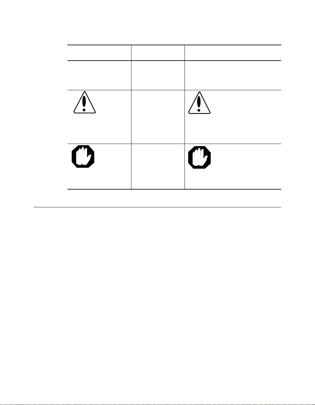
Note: A Note. The
Caution: A Caution. A
Warning: A Warning. A
Related Docu me nts
This section provides information on supporting documentation, including:
❑ 3Com Documents
information is
important
condition may
damage
software or
hardware
condition may
threaten
personal safety
Note: Use STP lobe
cables for yo ur s yste m.
Caution: Do not put
your installation
diskettes on a
magnetic surface.
This may damage the
diskettes.
Warning: We ar eye
protec tion when
performing these
maintenance
procedures.
❑ Reference Do cuments
xvi ONline 10BASE-T Security Module Installation and Operation Guide
Page 17

3Com Documents
The following documents provide ad ditional information on 3Com
products:
17-Slot ONline System Concentrator Installation and Operation
Guide – Explains how to install, operate, and manage the 3Com ONline
17-Slot Syste m Concentra tor (Models 5017C-LS and 5017 C with load
sharing).
6-Slot ONline System Concentrator Installation and Operation
Guide – Explains how to install, operate, and manage the 3Com ONline
6-Slot System Concentrator.
ONline Ethernet Management Module Installation and Operation Guide –
Describes h ow to install the ONline Ethernet Network Management
Module in the ONline System Concentrato r and explains the LEDs on the
module faceplate. This guide also provides instructions for connecting a
terminal to the module and describes the management commands
necessary to perform management tasks on the concentrator and on
remote devices.
ONline Management Commands Guide – Provides an a lphabetized
reference resource describing all ONline ma nagement commands.
For a complete list of 3Com documents, contact your 3Com representative.
Reference Documents
The following documents supply related background information:
Case, J., Fedor, M., Scoffstall, M., and J. Davin, The Simple Network
Management Protocol, RFC 1157, University of Tennessee at Knoxville,
Performan ce Systems International and the MIT Laboratory for Computer
Science, May 1990.
Rose, M., and K. McCloghrie, Structure and Identification of
Management Information for TCP/IP-based Internets, RFC 1155,
Performance Systems International and Hughes LAN Systems, Ma y 1990.
ONline 10BASE-T Security Module Installation and Operation Guide xvii
Page 18

Page 19

Introduction
1
This chapter describes the principle features of the ONline 10BASE-T
Security Module.
The ONline 10BASE-T Security Module
The ONline 10BASE-T Security Module is a 12-port IEEE 802.3 repeater
module that complies with the 10BASE-T standard. The module is designed
for use with the 3Com ONline System Concentrators using unshielded
twisted pair wiring. The Security Module provides the following features
and benefits:
❑ Provides jamming security for 12 10BASE-T ports
❑ Provides security from unauthorized transmissio ns
❑ Uses the 3Com ONgua rd™ technology to secure the network from
eavesdropping and i ntrusions
❑ Suppo rts up to 150 meter link distances on 22 gauge wire and up to
125 meters on 24 ga uge wire (the meter distance on 26 gauge wire
varies by cable type)
❑ Complies fully with the 10BASE-T signaling standard
Introduction 1 - 1
Page 20

❑ Features 'hot swap' capability so that you can install or remove the
module without having to power d own the conc entrator
In addition, the Security Module allows you to disable Link Integrity, which
allows the module to be connected to equipment that does not conform to
the 10BASE-T standard.
Before installing the Security Module into the ONline System Concentrator,
read the ONline System Concentrator Installation and Operation Guide.
Theory of Operation
The Security Module incorporates repeaters and twisted pair transceivers in
its hardware:
– Repeaters restore phase and frequency. Repeated signals
synchronize to the system clock and enter on the ONline
concentrator's TriChannel™ backplane. Outgoing signals
from the TriChannel backplane are sent directly to
transceive rs to be transmitted to twisted pair link
segments.
– Transceivers receive and restore amplit ude to incom ing
signals.
Application
Attach the Security Module to a pa tch or punchdown block using bundled
25-pair or 12-leg hydra cables. This provides connections for the 12 twisted
pair ports, as shown in Figure 1-1.
1 - 2 ONline 1 0B ASE-T Security Module I ns tallation and Operat ion Guide
Page 21
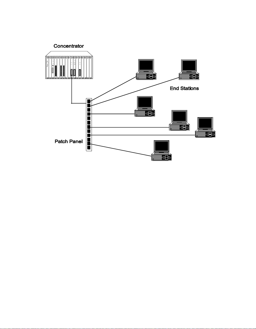
Figure 1-1. ONline 10BASE-T Security Module Application
ONline Management
A master ONline Ethernet Management Module (EMM) at Version 4.0 is
capable of managing the Security Module, including the Autolearning
feature.
A master ONline Token Ring Management Module (TR MM) at Version 3.0
is capable of managing the Security Module with the exception of the
Auto learning Feat ure. You must manually add MAC addresses to a port
MAC address table in order for a TRMM to manage the security features of
the Security Module. Refer to Chapter 4 for a description of the commands
to add MAC addresses to a po rt MAC address tab le.
Introduction 1 - 3
Page 22

Page 23

2
Designing and Expanding t he Network
This chapter contains configuration information that will help you to design
your netw ork. Install all equ ipment using only approved cables for proper
operation. Refer to Appendix A, Twisted Pair Connectors a nd Cables, for
information on twisted pair connector and cable requirements.
This chapter includes five sections which describe how to configure your
network using the ONline System Concentrator and the ONline 10BASE-T
Security Module. These sections include:
❑ Understanding Network Configurations
❑ Fibe r Backbone, Twisted Pair To-T he-Desk
❑ Twisted Pair Backbone, Twisted Pair To-The-Desk
❑ Patch Panels
❑ Redundant Links
Designing and Expanding the Network 2 - 1
Page 24

Understanding the General Rule s
As part of your network design, it is important to consider your network
size. For instance, is the network (end-to-end) 100 meters, 1000 meters,
4000 meters, or more? What are your plans for expansion? Your answers
play a role in how you configure your network. For example, once the
network expands beyond a certain size, you need to add a bridge or other
internetworking device.
This section describes general rules for configuring an Ethernet network
using fiber as the backbone medium. It also provides rul es to ensure that
your network configuration conforms to distance limitations imposed by
Ethernet and networking equipment.
This secti on includ es:
❑ Basic Network Rules
❑ LAN Equivalence
Basic Network Rules
This section outlines the basic network rules and 3Com’s recommendations
for these rules. For more hardware-specific information on the 10-Port
module, refer to Appendix A.
2 - 2 ONline 1 0B ASE-T Security Module I ns tallation and Operat ion Guide
Page 25

Table 2-1 outlines the seven basic rules to keep in mind when you construct
your network.
Table 2-1. Seven Basic Network Rules
Rule Definition Recommendations/Notes
1 If possible, use
10BASE-FB as the
backbone medium.
2 Wire the backbone in
a star topology to
isolate faults.
3 The maximum Fib er
Ethernet network
diameter is 4200
meters of fiber cable.
Use 62.5 micron cable to conform
with the IEEE 10B ASE-F and
upcoming ANSI FDDI standards.
Use ST-type connectors.
Make sure to l ay extra fiber cables.
The extra cost is small and you will
find yo u need th em as your net work
grows.
The st ar to po log y conf or ms t o FDD I
wiring as well -- just make sure to
run at least two fiber strands to
every backbon e co nnection.
The 4200 meters is the maximum
distance between any two
transceivers on the network.
The 4200 meters does not include
the transceiver cable (that is, drop or
patch cable) that connects a device
with an external transceiver.
Transceiver cables can extend up to
50 meters. Thus, total network
diameter can be as much as 4300
meters (420 0 m + 2 * 50 m)
betwee n any two nodes.
Designing and Expanding the Network 2 - 3
Page 26

Table 2-1. Seven Basic Network Rules (Continued)
Rule Definition Recommendations/Notes
4 Certain LAN devices
on the network shrink
the maximum Fiber
Ethernet network
diameter to less than
4200 meters.
5 Assume that one
meter of co axial or
twisted pair is equal to
one meter of fib er
cable.
Many LAN pro du cts de la y th e si gna l
that goes through them. This is
known a s equivalent distance. Ev ery
microsecond delay reduces the
maximum link distance. In fact,
every microsecond delay shrinks the
network diameter by approximately
200 meters of fiber cable. Table 2-2
lists the Equivalent Distances for
other 3Com products.
This is a conservative rule. For
example, the actual equivalence is
about 1.1 meters of coaxial for
every meter of fiber. For simplicity,
assume one meter.
2 - 4 ONline 1 0B ASE-T Security Module I ns tallation and Operat ion Guide
Page 27

Table 2-1. Seven Basic Network Rules (Continued)
Rule Definition Recommendations/Notes
6 The f iber l ink dist ances
must not exceed the
limits imposed by the
optical power budget.
7 When in doubt, use a
bridge.
In general, on 62.5 micron cable,
you can go up to 4000 meters
point-to-point using the ONcore or
ONline Fiber Mo dules. If you ha ve
poor quality cable or cross many
patch panels, you may have to
sacrifice some distance.
Some older Eth ernet fiber optic
products are less powerful than
ONcore Fiber Module optic s. So
when connecting to these products,
remember that the least powerful
device determines the maximum
point-to-point distan ce.
If you are not certain if you have
exceeded allowable network
distances, use a bridge to extend
the network.
Designing and Expanding the Network 2 - 5
Page 28

LAN Equivalence
LAN equivalen ce is the sum of both the incoming and outgoing module
port signals . Different modules, however, have different equivalent
distances. Table 2-2 lists the LAN product equivalent distances..
Table 2-2. LAN Product Equivalent Distances
LAN Produc t
ONline 10BASE-T Security Module (5112M-TPLS) 585
Incoming si gnal to TP port 420
Outgoing signal from TP port 165
ONline Ethernet 10BASE-FB Modules (5104M-FB,
5102M-FBP, 5104M-FBP)
Incoming signal to fiber port 140
Outgoing signal from fibe r por t 50
ONline Ethernet FOIRL Module (510 4M-FL) 560
Incoming signal to fiber port 330
Outgoing sign al from fibe r por t 230
ONline Ethernet 10BAS E-T Module (5108M-TP) 585
Incoming si gnal to TP port 420
Outgoing signal from TP port 165
Equivalent Fiber
Distance (meters)
190
ONline Ethernet 50-Pin Module
(5112M-TPL,
5112M-TPPL)
Incoming si gnal to TP port 420
Outgoing signal from TP port 165
2 - 6 ONline 1 0B ASE-T Security Module I ns tallation and Operat ion Guide
585
Page 29

Table 2-2. LAN Product Equivalent Distances (Continued)
LAN Produc t
ONline Ethernet 24-Port Module (5124M-TPCL) 585
Incoming si gnal to TP port 420
Outgoing signal from TP port 165
ONline Ethernet Repeater Module (5102M-AUIF) 800
Incoming si gnal to AUI port 600
Outgoing signal from AUI port 200
ONline Ethernet BNC Module (5106M-BNC) 900
Incoming signal to BNC port 450
Outgoing signal from BNC port 450
ONline Ethernet Transceiver Module
(5103M-AUIM)
3Com 10BASE-FB Star Coupler (9308S-FB) 180
ORnet Star Coupler (9314S) 180
Equivalent Fiber
Distance (meters)
0
IEEE Repeater 800
Fiber Backbone, Twist ed P air To-T h e-D esk
When you configure a network with unshielded twisted pair cabling
to-the-desk and fiber for the backbone, be aware of the following:
Designing and Expanding the Network 2 - 7
Page 30

❑ You must add a bridge if you exceed four full repeaters. The
four-repeater rule for Ethernet limits the number of 10BASE-T
modules between any two transceivers. When traffic goes into a port
on any repeater-based module and out the backplane, it counts as a
1/2 repeater. When the traffic goes into the module thro ugh one
port and out another port on the same or a different module, it
counts as one full repeater. Therefore, you must add a bridge if the
path from one transceiver to another exceeds the four-repeater rule.
❑ The equivalent fiber distance fo r the ONline Ethernet Fiber Modules
(se e Rule 4) is:
– 140 meters for signals that externally enter a Fiber Module
port
– 50 meters for signals that internally enter a Fiber Module
through the ONline Concentrator backplane
❑ The equivalent fiber distance for the Security Module (see Rule 4) is:
– 420 meters for signals that externally enter a Security
Module
– 165 meters for signals that internally enter a Security
Module through the ONline System Concentrator
backplane
For every pair of Security Modules that a signal goes through, deduct a
fiber equivalent distance of 585 meters (420 m + 165 m = 585 m) from the
overall alllowable network diameter. This is also true if a signal makes a
roundtrip through a single Security Module (enters the Security Mo dule
through one port and exits another port of the same Security Module). This
counts as 585 meters of fiber equivalent distance, and as a full repeater.
Fiber Backbone, Twisted Pair To-The-Desk Example
In the sample configuration shown in Figure 2-1, we determine if the
transceivers are within legal Ethernet limits. 22-gauge unshielded twisted
pair cable is used to connect 10BASE-T Transceivers to the Security Modules
in the concentrators.
2 - 8 ONline 1 0B ASE-T Security Module I ns tallation and Operat ion Guide
Page 31
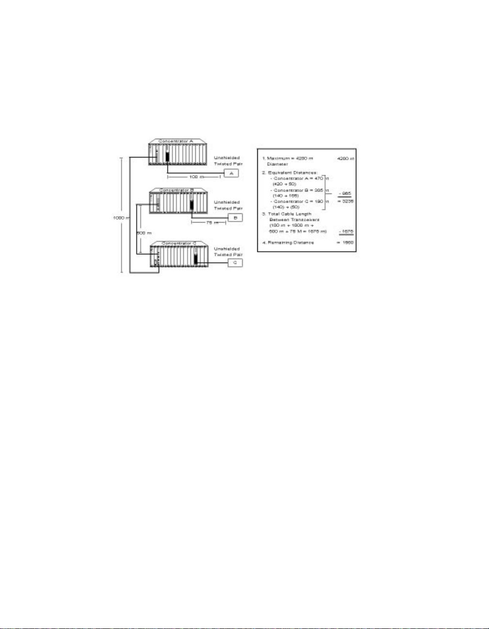
Using the sample configuration below, identify the two transceivers that
are likely to be the greate st fiber equivalent distance apart. In this case,
they are 10BASE-T Transceivers A and B.
Figure 2-1. Sample Configuration Distance Calculation
To determine if your network configuration is legal:
1. Use 4.2 km (4200 m) since this is the maximum network diameter for
a pure fib er network ( see Rule 3) .
2. Calculate the equivalent distances for each concentrator, and
subtract the totals from 4200 (refer to Figure 2-1 for details).
3. Subtract all cable lengths betw een the two transceivers. If the result
is greater than zero, the configuration is within legal Ethernet limits
(se e Rule 5).
For the con figuration shown in Figure 2-1 to work, ensure the fiber
equivalent distance between transceiver A and transceiver B is less than
4200 meters. As the calculation illustrates, 1560 meters remain for
expansion in this configuration.
Designing and Expanding the Network 2 - 9
Page 32

Do not exceed the distan ces as defin ed in Table 2-2 for the link from a
Security Module to a 10BASE-T Transceiver.
Table 2-3. Maximum Link D istance on Twisted Pair
Cable Gauge Supports Link Distances Up To:
Unshielded Twisted Pa ir:
10BASE-T
22 (.6 mm) 100 m
24 (.5 mm) 100 m
Normal Squelch
Twisted Pair Backbone, Twisted Pair To-The-Desk
In constructing a twisted pair backbone, one additional configuration rule
must be considered. Ensure there are no more than eight Security Modules
in the path between any two transceivers due to Ethernet's four-repeater
rule. This is because each Security Module counts as a 1/2 repeater unless
the signal goes in one port and out another port of the same module, in
which case the module counts as a full repeater.
If you have more than eight Security Modules serially connected, add a
bridge. Each bridge creates a subnetwork. Each subnetwork can have its
own 420 meter network diameter.
The configuration in Figure 2-2 illustrates a possible unshielded twisted pair
network using 22 gauge cable.
2 - 10 ONline 10BASE-T Security Module Installation and Operation Guide
Page 33

Figure 2-2. Unshielded Twisted Pair Network
While there is no fiber in the configuration in Figure 2-2, you can calculat e
the fiber equivalent distance as follows:
Total link distance: 100 m + 100 m + 100 m + 50 m + 20 m = 370 m
Total equivalent distance of the Security Modules: (4 * 420 m) + (4 * 165 m) =
2340 m (signal externally enters four Twisted Pair Modules: 4 * 420m)
(signal enters four Twisted Pair Modules from the backplane: 4 * 165 m)
Total equivalent distance: 370 m + 2340 m = 2710 m
Since the totalequivalent distance (2710 m) is less than 4200 meters, this example is
a legitimate configuration.
Patch Panels
Patch panels weaken signals that pass through them, thereby reducing
achievable link distances. 3Com assumes the use of one patch panel in the
100 meter link distance calculations specified in this manual. However, each
additional patch panel in the link reduces the 100 m eter link distance by
approximately 10 meters.
Designing and Expanding the Network 2 - 11
Page 34
In the exam ple shown in Figure 2-2, if two patch panels were used
between the top right PC and the top right concentrator, you would have
to shorten the link distance of 100 meters to 90 meters. This is because the
maximum allowable link distance on 22 gauge wire using 10BASE-T
signaling with two intervening patch panels is 100 meters minus
approximately 10 meters.
Note that a patch panel installed between the bottom right PC and the
bottom left concentrator would not affect the link because it is only 20
meters away.
Redundant Links
You can implement twisted pair link redundancy between ONli ne System
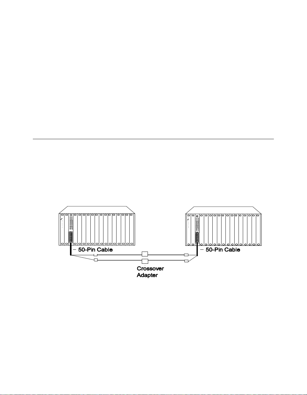
Concentrators using network management. Figure 2-3 shows an exampl e
of a redundant configuration between concentrators using Security
Modules.
Figure 2-3. Redund ant Twisted Pair Configuration
2 - 12 ONline 10BASE-T Security Module Installation and Operation Guide
Page 35

To set link redundancy between two Security Modules:
1. Connect two links to two ports on the 50-Pin Telco cables between
the modu le s. U se a cr os so ver ad ap ter be tw ee n each lin k be ca us e the
links are designed to be connected to a station's port, not to other
concentrator ports.
2. Use the SET PORT {slot.port} MODE REDUNDANT {slot.port}
network management command to specify which port is the primary
link and which is the backup link.
Note: If the Security Mo dules are po wered down, and powered
up without a 3Com network management module present,
a network loop could occur. To prevent a potential network
failure, set the DIP switch for the backup port to disable.
3. Once link redundancy is configured, a switchover occurs under two
conditio ns: a link failure or a port partition . The switchover occurs
when the primary link fails.
4. Once the switchover occurs and the backup link become s
operational, a switchover back to the primary link happens
automatically once the problem is resolved.
Note: If you use a Secu rity M odule port as a bac kbone connect ion
ensure that Security Mode is disabled for the port or it will
experience security intrusion attempts.
Refer to the appropriate network management module installation and
operation guide for information on setting redundancy between Security
Module ports.
Designing and Expanding the Network 2 - 13
Page 36

Page 37

3
This chapter describes the installation procedures and initial setup
commands for the ONline 10BASE-T Security Module. For your convenience,
a quick installation chart is included.
Note: Read the precautionary procedures before unpack ing the
The remainder of this chapter describes:
Installing and Operating the Module
module.
❑ Setting the DIP S witch
❑ Installing the Module
❑ Configuring the Module
❑ Showing Module Configurations
❑ Monitoring the Front Panel
Installing and Operating the Module 3 - 1
Page 38

Precautionary Procedures
Electrostatic discharge (ESD) can damage static-sensitive device s on circuit
boards. Follow these precautions when you handle the Security Module:
❑ Do not remove the board from its anti-static shielding bag until you
are ready to inspect it.
❑ Handle the board by the faceplate.
Use proper grounding techniques when you install the Security Module.
These techniques in clude using a foot stra p and grounded mat or wearin g
a ground ed static discharge wrist strap . An alternate method is to touch
the grounded rack or other source o f ground just before you handle the
module.
Quick Inst allation Ch art
Table 3-1 outlines the steps necessary to complete the installation of your
module. If you are familiar with these instructions, you may want to use
this table as a checklist; otherwise, consult the remainder of this chapter.
Table 3-1. Procedures for Completing Installation
Step Procedure Reference
1. Verify that your network complies
with the basic rules for network
design.
2. Unpack the module. Unpacking Procedures
3. If you do not have a management
module installed in the concentrator,
set the DIP swi tch settings to your
specifications.
3 - 2 ONline 1 0B ASE-T Securit y Module I ns tallation a n d Operat ion Guide
Chapter 2/Designing &
Expanding the Network
Setting the DIP Sw it ch
Page 39

Table 3-1. Procedures for Completing Installation (Continued)
Step Procedure Reference
4. Install the module into a blank slot in
the concentrator and tighten the
faceplate screws.
5. Establish connections from the
Security M odule to devices or a
10BASE-T transceiver using the
appropriate connectors and cabling.
6. If you have a management module
installed in the concentrator,
configure the module using the
management commands.
7. Verify LED status for normal
operation.
Note: To res olve pote ntial prob lems,
consult the trouble sho oting
techniques in Chap ter 5.
Installing the Module
Installing the Module
Configuring the Module
LED and Network
Verification
Installing and Operating the Module 3 - 3
Page 40

Unpacking Procedu res
To unpack yo ur Security Module:
1. Verify that the Security Module is the correct module by matching the
model number listed on the side of the shipping carton to the model
number you ordered.
Note that the p roduct mod el number printed on the shipping box
differs from the model number on the product. The model number
on the shipping box contains the prefix ’3C9’.
If the module appears to be damaged, return it to the anti-static
shielding bag, repack it in the shipping carton, and contact your local
3Com supplier.
2. Remove the Security Module, in its anti-static bag, from the shipping
carton.
3. Remove the module from the anti-static shielding bag an d inspect it
for damage. Save the package of screws in the carton; you will need
them when you attach a cable to the module. Always handle the
Security M odule by the faceplate, being careful not to touch the
components.
Keep the shipping carton and anti-static shielding bag in which your
module was s hipp ed in case you wa nt to rep ack age th e modu le f or st ora ge
or shipment. Record the serial number of your Security Module. A log for
information specific to your modules is provided under the Slot Usage
Chart in Appendix B of the ONline System Concentrator Installation and
Operation Guide.
3 - 4 ONline 1 0B ASE-T Securit y Module I ns tallation a n d Operat ion Guide
Page 41
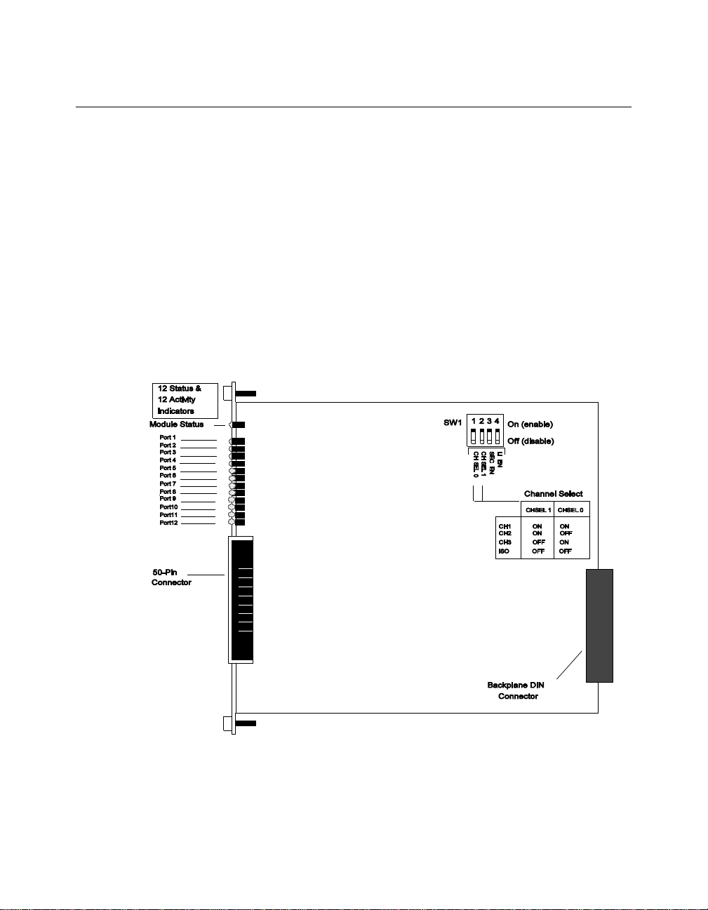
Setting the Dip Sw itc h
The Secu rity Modul e has one 4-switch DIP switch (SW1) located on the
module. The functions of the DIP switch settings on the Security Module
are ignored if a management module is already installed in the
concentrator. For this reason, use management commands, rather than the
DIP switch, to configure the module.
If a management module is installed in the concentrator, you may skip this
section and procee d to the Installing the Module section later in this
chapter.
Figure 3-1 shows the location and default settings of the DIP switch.
Figure 3-1. Securi t y Module D i p S w itch SW 1 Location
Installing and Operating the Module 3 - 5
Page 42

Network selection switches 1 a nd 2 enable you to select a channel for the
module. Switches 1 and 2 are factory set to On. Therefore, the S ecurity
Module is initially configured to network 1. To reconfigure the module to a
different network, refer to the information in .
Table 3-2. DIP Switch SW1 Network Selection Settings
Switch 1 Switch 2 Network Selec tion
Switch Settings On On 1 (default)
Off On 2
On Off 3
Off Off Isolated (mo dule
operates
independently of the
three backplane
networks)
Switch 3 (Security) allow s you to enabl e or disable Security mode and
enable or disable port mode for all 12 ports on the Security Module. Switch
3 is confi gured to affect both Security mode and the port mode setting in
order to pro tect your ports in the event the management modul e fails.
When th e Security switch is set to enabled, port mode is set to disabled.
Conversely, when the Security switch is set to disabled, port mode is set to
enabled.
This dua l purpose setting pro vi des maximum security for all ports on the
Security Module and also provides you with the flexibility of using the ports
as non-secure ports in the event the management module fails. Without
management, you may elect to have traffic contin ue to pass through the
non-secure ports. However, your environment may require secure ports at
all times. In this situation, you would choose to disable the ports rather
than keep them enable d in a non-secure environment.
3 - 6 ONline 1 0B ASE-T Securit y Module I ns tallation a n d Operat ion Guide
Page 43

Switch 4 (Link Integrity) allows you to enabl e or disable Link Integrity.
Table 3-3 li sts the functions and default settings for switches 3 and 4.
Table 3-3. DIP Switch SW1 Security and Link Integrity Setti ngs
Switch Function
3 (Security) Enable or disable
security and enable
or disabl e port mode
for all 12 ports
4
(Link Integrity)
Enable or disable
link integrity for all
Factory
Default
enable Security
enable disable enable
Switch Setting
Off On
Security
disable/
Port
enable
enable/
Port
disable
12 ports .
The complete definition of each dip switch function is contained in the
Configuring the Module section later in this chapter.
Installing and Operating the Module 3 - 7
Page 44

Installing the Module
You do not need to power down the ONline System Concentrator to install
the Security Module. You can insert the module while the concentrator is
operating (this is called a ho t s wap).
This section describes:
❑ Installing the Cabl e Ti e-W rap Kit
❑ Installing the Module
Installing the Cable Tie-Wrap Kit
A cable tie-wrap kit is included with the Security Module. If you use a cable
connector other than a 180° cable connector (for example, a 90° cable
connector), you must secure the cable to the module connector using the
tie-wrap kit. 3Com recommends using a 180° cable connector with the
Security Module.
If you are using a 180° cable connector with the Security Module, skip this
procedure a nd proceed to the next section, I nstalling the Module.
Note: Perform the tie-wrap kit installation procedure prior to
installing the module into a 3Com ONline System
Concentrator.
The tie-wrap kit contains:
❑ Kit card containing kit part number
❑ 1 Phillips-head screw
❑ 1 Tie-wrap bracket
❑ 3 Tie-wraps
3 - 8 ONline 1 0B ASE-T Securit y Module I ns tallation a n d Operat ion Guide
Page 45

To install the tie-wrap kit:
1. Remove the hex nut from the bo ttom of the connector located on
the module faceplate.
2. Using the Phillips-head screw provided in the tie-wrap kit, attach the
tie-wrap bracket to the m odule (Figure 3-2).
Figure 3-2. Attaching the Tie-Wrap Bracket to the Module
3. Insert the tie-wrap through the opening on the tie-wrap brac ket.
Installing and Operating the Module 3 - 9
Page 46

4. Connect the 9 0° cable connector to the module connecto r using a
tie-wrap to secure the cable connector to the module (Figure 3-3).
Figure 3-3. Attaching Cables With 90° Connectors
5. Wrap the tie-wrap around the cable connector to secure the cable
connector to the module connector.
Caution: Do not fasten the tie-w rap around the module ejectors.
3 - 10 ONline 10BASE-T Security Module Installation and Operation Guide
Page 47

Installing the Module
To install the Secu rity Module:
1. If you do not have a management module installed in the
concentrator, make sure you set the DIP switches properly on the
board, if different than the default settings.
A management module is required to configure the security features
of the Security Modu le. Without management, the Security Module
functions as a non-secure 10BASE-T module.
2. Locate an open slot in the concentrator. Remove the blank panel on
the concen trator to expose a slot for the module.
Insert the module into the board guides at the top and bottom of the
slot and slide it into the concentrator by firmly pressing the top and
bottom of the faceplate. Make sure the connector is well-seated into
the backplane of the concentrator. Figure 3-4 shows the installation
of the m odule.
Figure 3-4. Installing an ONline 10BASE-T Security Module
3. Fasten th e spring-loaded screws on the front of the S ecurity Mod ule
faceplate to the concentrator with your fingers (do not overtighten).
Inst alling and Oper ating the Module 3 - 11
Page 48
4. Remove the lo ng scr ew (if prese nt) fr om th e 50-pin cable . Disc ard this
screw.
5. Remove the two cable-fastening screws from the Security Module
shipping carton.
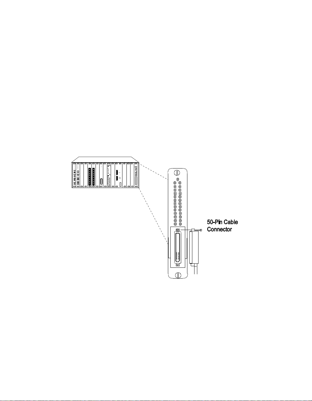
6. Attach the 50-pin cable connector to the 50-pin connector on the
front of the module.
7. Install the two screws in the top a nd bottom screw holes of the
50-pin cable connector to secure the cable to th e module connector
as shown in Figure 3-5. (Only one of the cable-fastening screws may
be installed depending on the angle of the 50-pin cable connector.)
Figure 3-5 . ONline 10BASE-T Security Module Cable Connection
8. Attach the other end of the cable to a 10BASE-T Transceiver or a
10BASE -T Adapt er Card.
3 - 12 ONline 10BASE-T Security Module Installation and Operation Guide
Page 49

The 50-p in Telco-type connector connects to 12 10BASE-T-compliant
ports using a 12-leg hydra cable. This module can be attache d using
the 12-leg hydra cable to a patch panel or punch-down block, which
provides connections for the 12 twisted pair ports.
The next section describes the features you can set for the Security Module.
Configuring the Module
The ONline management modules (EMM, TRMM, and FMM) provide
management capabilities for the ONline System Concentrator and its
modules. If a management module is already installed, the DIP switch
settings on the Security Module are ignored. For this reason, 3Com
recommends that you use management commands, rather than the DIP
switches, to configure the module and the ports.
When you first install the module and network management is present:
1. The network defaults to isolated mode and the ports are
automatically disabled so that unapproved users cannot be added.
2. You must enable the ports you wish to use and set the module to the
appropriate network through the management commands.
The following sections describe the mana gement commands to set the
above features. Refer to the appropriate ONline management module
installation and operation guide and the ONline Management Commands
Guide for additional informatio n on available netw ork management
features.
Inst alling and Oper ating the Module 3 - 13
Page 50

Port Enable
You can enable or disable use of the 12 ports on the Security Module.
When a port is ena bled, it can transmit and receive data onto the network
to which the module is assigned. 3Com recommends that you disable all
unused ports on the Security Module to prevent network tampering.
Enter the following management command to enable all the ports on the
module in slot 3.
ONline> set port 3.all mode enable [ENTER]
Network Assignment
The Security Module is equipped with the tech nology to work with the
ONline System Concentrator's unique TriChannel™ architecture. This
feature allows you to assign the module to any of three networks or
isolated on the ONline System Concentrator backplane. Refer to the ONli ne
System Concentrator Installation and Operation Guide, Chapter 1, for a
discussion of the ONline TriChannel architecture.
Enter the following management command to assign the Security Module
in slot 3 to Ethernet network 1.
ONline> set module 3 network ethernet_1 [ENTER]
Port Redundancy
ONline network management allows you to set redundancy between ports.
Enter the following management command to set redundancy between
ports on the Ethernet module in slot 5.
ONline> set port 5.1 mode redundant 5.2 [ENTER]
Use the MODE NON_REDUNDANT option to turn off redundancy between
ports. Recommended redundancy c onfigurations are shown in Chapter 2,
Designing and Expand ing the network.
3 - 14 ONline 10BASE-T Security Module Installation and Operation Guide
Page 51

If you set up redundancy between a secure port and a non-secure port
(whether on a Security Module port or other module port), a warning
message is displayed to terminal management. The warning informs you
that this configuration has the potential to automatically cause a change in
security when the primary port fails and the secondary port becomes
activated.
Link Integrity
In general, enable Link Integrity for the Security Module to conform to
the10BASE-T standard. Disable Link Integrity to connect to older equipment
that does not conform to the 10BASE-T standard.
Enable Link integrity at both ends or disable Link Integrity at both ends of
the connection. If one end of the connection is different, the module with
Link Integrity en abled reports a Link Integrit y error.
If you enable a port and disable Link Integrity, the Status LED for that port
is on for 10 seconds and blinks off for 400 msecs to indicate that Link
Integrity is disabled.
Enter the following management command to enable Link Integrity for all
ports on the Ethernet module in slot 5.
ONline> set port 5.all link_integrity enable [ENTER]
Module Security
The Module Security DIP switch allows you to enable or disable security for
the module. 3Com recommends that you leave this switch in its factory
default setting (Off). This setting ensures that in the unlikely event of a
concurrent failure of both the master management module a nd
concentrator power, the Security Module ports will power up with ports
disabled in a concentrato r without network management.
Note: When the Security switch is set to enabled, port mode is
set to disabled. Conversely, when the Sec urity switch is set
to disabled, port mode is set to enabled.
Inst alling and Oper ating the Module 3 - 15
Page 52

Use the following command to enable security for all of the ports on the
Security M odule in slot 3.
ONline> set security port 3.all mode enable [ENTER]
Autopartition Threshold
Autopartition threshold tells network management the number of collisions
to allow be fore automatically partitioning a port. The options are 31, 63,
127, and 255. The factory default is 63. The 10BASE-T specification lists a
minimum of 31 collisions prior to partition, but 31 collisions can cause ports
to partitio n more frequently than necessary .
The additional options (127 and 255) a re for debugging purposes, an d
therefore not recommended for use in live networks.
Enter the following command to define 127 collisions for the module in
slot 3.
ONline> set module 3 autopartition_threshold 127_coll [ENTER]
Saving Module Configurations
After configuring the module and port settings, issue the SAVE
MODULE_PORT command from the management module to save the new
configuration settings.
ONline> save module_port [ENTER]
Reverting Module Configurations
Issue the REVERT command as shown to return a module to the
configuration settings that were in effect as of the last save.
ONline> revert module_port [ENTER]
3 - 16 ONline 10BASE-T Security Module Installation and Operation Guide
Page 53

Showing Modu le Conf ig urat ions
You can display status information about the Security Module using the
following management commands:
❑ SHOW MODULE
❑ SHOW MODULE VERBOSE
❑ SHOW POR T
❑ SHOW POR T VERBOSE
The following command displays detailed information about the Security
Module in slot 3:
ONline > show mod ul e 3 verbose [ENTER]
Slot Module Versio n Network General In fo rma ti on
3 5112M-TPLS 001 ETHERNET_1
5112M- TP LS: ONline 10BASE-T Security M odu le
Networ k Dip Sett in g: ETHERNET _1
Auto-p ar tit io n T hresh ol d: 63 CO LLI SI ONS
The followi ng command displays detailed information for port 1 o n a
Security M odule in slot 12.
ONline > show port 12. 1 verbose [ENTER]
Port Display for Module 5112 M-T PL S :
Port Mode Status Network General Inf ormat ion
12.01 DISABLED LINK FAILUR E ETHER NET_1
Port A le rt: ENABLED
Port C on nec to r: TELCO
Mode D ip Se tt ing : ENABLED
Securi ty Di p Set ting DISABLE D
Link I nt egr it y D ip Sett ing : ENABLED
Inst alling and Oper ating the Module 3 - 17
Page 54

The following output is an example of the SHOW PORT ALL VERBOSE
command issued for the ports of a Security Module installed in slot 12 (only
the output for ports 1, 2, and 3 are shown):
ONline > show port 12.all verbose [ENTER]
Port Mode Status Network General Inform ati on
12.01 DISABLED LINK FAILURE ISOLATED
Port Alert Filter: DISABLED
Port C on nec to r: TELCO
Link I nt egr it y: ENABLED
12.02 DISABLED LINK FAILURE ISOLATED
Port A le rt Fi lte r: D IS AB LED
Port C on nec to r: TELCO
Link I nt egr it y: ENABLED
12.03 DISABLED LINK FAILURE ISOLATED
Port A le rt Fi lte r: D IS AB LED
Port C on nec to r: TELCO
Link I nt egr it y: ENABLED
Monitoring the Front Panel
The Security Module has 12 Activity and 12 Status LEDs on the front panel
that indicate the state of the ports. The LEDs allow you to m onitor the
status of each port. The front panel also contains a Module Status indicator
that indicates the state of the module. Fig ure 3-5 shows the location the
LEDs. Each LED indicates the state of its port as described in Table 3-4.
3 - 18 ONline 10BASE-T Security Module Installation and Operation Guide
Page 55
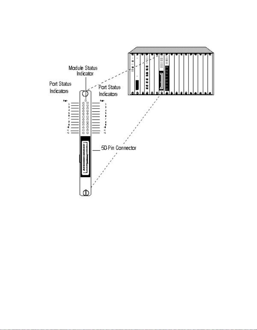
Figure 3-6. Security Module Fac eplate
Inst alling and Oper ating the Module 3 - 19
Page 56

Table 3-4. Interpretation of the Security Module LEDs
LED
Name
Activity
(Ports
1-12)
Status
(Ports
1-12)
Color State Indicates
yellow Off No packets are received on the
segment.
On Constant activity on the segment.
Blinking Normal activity on the segment.
green Off Port disabled.
On Port enabled and link OK or Link
Integrity disabled.
1 blink Link failure.
2 blinks Port partitioned.
3 - 20 ONline 10BASE-T Security Module Installation and Operation Guide
Page 57

LED and Network Verificati o n
Once the module is installed, verify its operation through the front panel of
the ONline Controller Module. The Controller Module is equipp ed with an
LED test button on the front panel. Use the LED test button to verify LED
operation and verify network assignment.
When you press this button, the Controller Module initiates a test to all
modules in the concentrator. All LEDs should respond by lighting
continuously for approximately five seconds. Any LED that does not light is
defective.
After the five seconds elapse, the diagnostic continues w ith a network
check of all modules. Each Status LED should respond by blinking the
number of times to correspond with the network to which the module is
assigned. The network check sequence repeats five times. If a module is in
isolated mode, the Status LEDs on the module remain off. The Activity LED
remains on during the network check sequence. This test does not disrupt
network operation. Table 3-5 explains the network check codes
Table 3-5. Network Check Codes
LED State Network Configuration
1 Blink Module is configured for network 1
2 Blinks Module is configured for network 2
3 Blinks Module is configured for network 3
Off Isolated (module operates independent of
any network)
Inst alling and Oper ating the Module 3 - 21
Page 58

Page 59

4
Configuring Secur it y Features
This chapter describes the security features of the ONline 10BASE-T Security
Module and includes the management commands necessary to configure
and monitor security function ality.
A master EMM at Version 4.0 is required to manage the features of the
Security Module, including A utolea rning. A mas ter TRMM a t V ersion 3.0 is
required to manage the features of the Security Module with th e exce pt io n
of the Autolearning Feature. You must manually add MAC addresses to a
port MAC address table in order for a TRMM to manage the security
features of the Security Module. Refer to the section, Defining a MAC
Address Manually, for a description of the command to add MAC addresses
to a port MAC address table.
The remainder of this chapter describes:
❑ Configuring Security Features
❑ Showing Secu rity Configurations
❑ Clearing Security Configurations
❑ Using the 3Com MIB Security Variable s
Configuring Security Features 4 - 1
Page 60

Quick Refere nc e for Config u ring Se curit y
Table 4-1 outlines the steps necessary to configure the security features of
your module. These procedures and command examples are explained
further throughout this cha pter. If you are familiar with these instructions,
you may want to use this table as a c hecklist.
Table 4-1. Quick Reference for Configuring the Security
Module
Procedure Command
1. Di sable A utolea rning Mask
to allow the EMM to
Autolearn MAC addresses
for ports. (Enabl ing
Aut olear ning Mask
prevents the E MM from
learning a port's associated
MAC addresses.)
2. Di sable Security Mode to
allow the EMM to Autolearn
MAC addresses for ports.
3. Enabl e the ports to allow
traffic to pass through the
network so the EMM can
lear n whic h MAC addr e sse s
are associated with which
ports. (You must enable
ports in order for
Autolearning to run.)
SET SECURITY AUTOLEARN MASK
SET SECURITY PORT MODE
SET PORT MODE
4 - 2 ONline 1 0B ASE-T Securit y Module I ns tallation a n d Operat ion Guide
Page 61

Table 4-1. Quick Reference for Configuring the Security
Module (Continued)
Procedure Command
4. Initiate Autolearning to
enable the EMM to
automatically learn the
valid MAC addre ss es
associated with a ports.
5. Down lo ad the learned
MAC addresses from the
Autolearning database to
the port MAC address table.
TRMM Note: The TRMM does
not support Autolearning.
Therefore, you if you are using
a TRMM to manage the
Security Module, you must
manually add MAC addresses
to a port MAC address table.
6. Define the Security type:
Eavesdropping_only,
Intrusion_only, or Full.
Note: Security Mode is
automatically e nabled
when you is sue the SET
SECURITY PORT
SECURITY_TYPE command.
SET SECURITY AUTOLEARN CAPTURE
SET SECURITY AUTOLEARN
DOWNLOAD
SET SECURITY PORT MAC_ADDRESS
SET SECURITY PORT SECURITY_ TYPE
7. Define the corrective action
the EMM is to take upon a
Security Intrusion att empt.
8. Save Security configuration
values.
SET SECURITY PORT ACTION_ ON_
INTRUSION (only necessary if Security
Type is set to Intrusion_Only or Full)
SAVE SECURITY
Configuring Security Features 4 - 3
Page 62

Configuring Security Features
This section describes the security features of the Security Module,
including Eavesdropping Security and Intrusion Detection. Included in this
section are the features you must configure to enable security on the
module:
❑ Define port security type
❑ Define port action on intrusion
❑ Configure Autolearning Ma sk
❑ Enable ports
❑ Configure autolearning
❑ Download the Autolearning database
Security configurations from the Security Module are automatically
uploaded to a newly elected master management module or installation of
a new master management module. This automatic uploading feature
ensures that the Security Module configurations are always retained and
eliminates the need for you to reconfigure the new master.
Note: If you issue security commands (with the exception of MAC
address settings) specifying the 'all' option, all Security
Module ports in the concentrator are affected by the
command. If you are running an Advanced EMM, all other
Ethernet modules in the concentrator that support security
are also affected.
Eavesdropping Security
Eavesdropping securi ty is a port jamming feature that prevents users from
accessing data transmitte d to other users on the network. This type of
security:
4 - 4 ONline 1 0B ASE-T Securit y Module I ns tallation a n d Operat ion Guide
Page 63
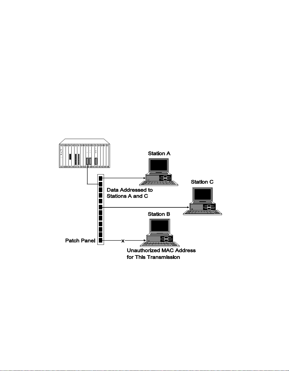
❑ Allows the Security Module to deliver packets only to the end station
to which a packet is addres sed.
❑ Prohibits unauthorized end stations from listening (eavesdropping)
on packets that are not specifically addressed to them.
If a port receives a packet (from the ONline backplane) that is not targeted
to any of the valid addresses associated with that port, the Security Module
does n ot al low t h at p ac ket t o be d el ive r ed i nt act t o th e end s t atio n. I nst ea d
of delivering valid data to an unauthorized port, the module 'jams' the data
by transmitting to the unauthorized port a data pattern of alternating zeros
and ones.
Figure 4-1. Example of Eavesdropping Security
Intrusion Detection
Intrusion Detectio n allows the Security Module to prevent delivery of
packets transmitted from un authorized stations on the network. If a port
receives a packet from its end station which contains an invalid source
Configuring Security Features 4 - 5
Page 64
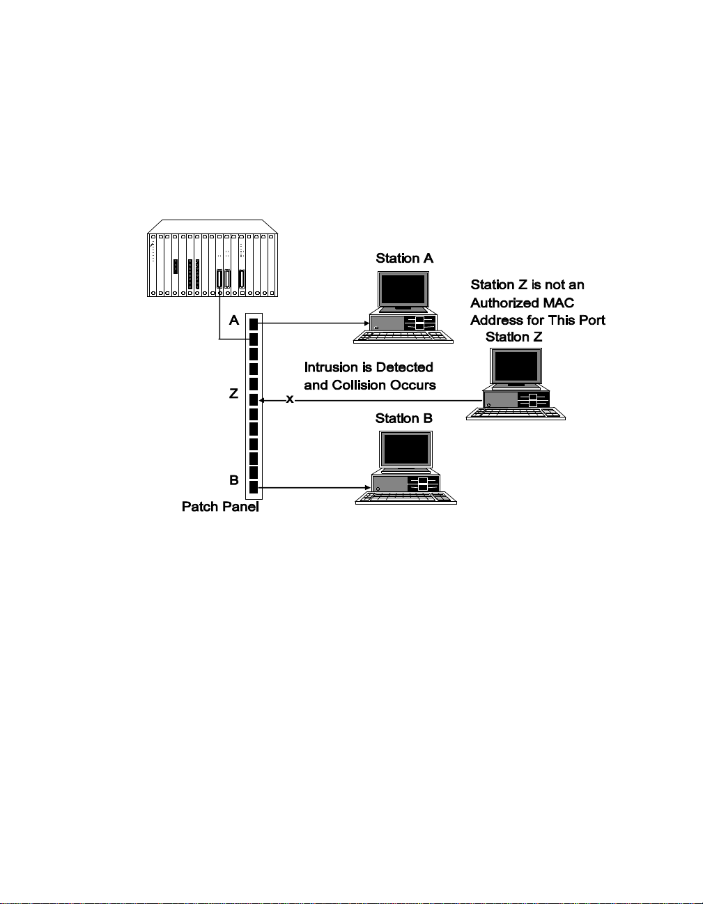
address, the module forces a collision. The collision prevents intruding end
station s from gaining access to a port and transmitting unauthorized data
over the network.
Figure 4-2 illustrates an example of an Intrusion Detection configuration.
Figure 4-2. Example of Intrusion Detection
Defining Port Security Type
You must define a security typ e for each port on the Security Module.
Issue the following command to configure the security type 'full' for all
ports on the Security Module in slot 3.
ONline> set security port 3.all security_type full [ENTER]
You may elect to configure ports for Eavesdropping Security only, Intrusion
only, or Full (which includes both Eavesdropping and Intrusion). The default
setting for Security Type is Full.
4 - 6 ONline 1 0B ASE-T Securit y Module I ns tallation a n d Operat ion Guide
Page 65

Security Mode is automatically enabled when you issue the SET SECURITY
PORT SECURITY_TYPE command.
Security Type is automatically configured to Full (which includes bo t h
Eavesdropping and Intrusion security) when you issue the SET SECURITY
PORT MODE ENABLE command .
Note: Security mode must be disabled in order for the EMM to
Autolearn MAC addresses for ports that have Security Type
configured for Intrusion_only or Full. If Security Mode is not
disabled for each port that is configured for Intrusion
Security:
– MAC addre ss es are not Auto learned
– The ports report an intrusion
Defining Port Action on Intrusion
An additional feature of Intrusion Detection provides you with the ability to
define on a per-port basis the corrective action a management module is to
take when a Security Module port experiences a security intrusion attempt.
Each option provides Intrusion Detection and data collision on the intruding
packet. You may elect to have the management module perform one of
the following actions:
❑ Disable the port and send a trap (disabl e_and_trap)
❑ Only disable the port (disable_only)
❑ No management action (no_action)
❑ Only send a trap to stations defined in the management module's
communi ty table (trap_only)
Issue the following command to define disable_and_trap as the corrective
action a management module will take upon a security Intrusion attempt
for all ports on the module in slot 3.
Configuring Security Features 4 - 7
Page 66

ONline> set security port 3.all action_on_intrusion disable_and_trap [ENTER]
The default setting for action_on_intrusion is disable_and_trap.
Note: For a security intrusion attempt to be logged into the
Intruder li st, you must configure the actio n_on_intrusion
setting for either disable_and_trap or trap_only. B oth
settings allow a trap to be sent upon an intrusion, which
also logs an entry into the Intruder list .
Configuring Autolearning Mask
Autolearning Mask:
❑ Allows or prevents a port's MAC addresses from being learned by the
EMM du ring Autolearning.
❑ Determines if the EMM is allowed or prevented from downloading
learned MA C a ddresses to the ports.
The Autolearn Mask command either allows (disable the mask) or prevents
(enable the mask) the EMM from learning or downloading MAC addresses
for ports.
Issue the following command to allow the EMM to learn MAC addresses
during Autolearning for all ports on the Security Module in slot 3.
ONline> set security autolearn 3.all mask disable [ENTER]
Enabling Ports
For an EMM to lea rn MAC addresses fo r ports through Autolea rning, the
ports must be enabled (at some point) to allow network traffic to pass
through. Therefore, ensure that ports are enabled prior to initiating
Autolearning. Note that Autolearning will run on a disabled port, however,
no MAC addresses will be learned.
4 - 8 ONline 1 0B ASE-T Securit y Module I ns tallation a n d Operat ion Guide
Page 67

Issue the following command to enable all the ports on the Security
Module in slot 3.
ONline> set port 3.all mode enable [ENTER]
Configuring Autolearning
Autolearning uses the network monitoring features of the EMM to provide
a mechanism which:
❑ Learns the MAC addresses of the stations that have been sending
packets to the EMM network
❑ Continuously monitors network activity
An EMM at Version 4.0 is required to configure Autolearning.
Once the Autole arning capture process beg ins, the EMM takes an
instantaneous 'snapshot' of the MAC addresses tha t have passed through
the specified ports. These addresses are stored in the Autolearn ing
database.
Issue the following command to initiate Autolearning capture for all ports
on the Security Module in slot 3.
ONline> set security autolearn 3.all capture [ENTER]
The followi ng steps are initiated once the Autolearn Capture command is
issued:
1. The Autolearning database (the storage area for learned MAC
addresses) is cleared.
2. All of the MAC a dd res ses ob ser ved on t he sp ec ifi ed por ts are enter ed
into the Autolearni ng database.
3. The entries from the specified ports' MAC address table are copied
into the Autolearni ng database.
Configuring Security Features 4 - 9
Page 68

4. The result of this copy is a combination of the existing MAC
addresse s associate d with a port, and the MAC ad dresses recently
learned. (Remember tha t a port must have its Autolearning Mask
disabled in order for MAC addresses to be learned.)
5. If MAC addre ss es for the specified ports currently exist in the
Autolear ning database, the following message is displayed when the
Autolearn Capture command is issued:
Note: overwriting previously autolearned addresses.
If no MAC addresses were learned for the specified ports, then the
following message is displayed:
Autolearn capture done; learned 0 addresses total.
6. Upon completion of Autolearning, the following message is
displayed:
Autolearn capture done; learned x addresses total.
(where x indicates the total number of addresses now stored in the
Autolearning Database)
The stored MAC addresses are now ready to be downloaded to the
Security Module ports. Refer to the section, Down loadi ng the Au to lear ning
Database, further in this chapter.
Note: Security M ode must be disabled in order for the EMM to
Autolearn MAC addresses for ports that are configured for
Security Types Intrusion_only or Full. If Security mode is not
disabled for each port that is configured for Intrusion
Security:
– MAC addre ss es will not be Autolearned
– The ports will report an intrusion
4 - 10 ONline 10BASE-T Security Module Installation and Operation Guide
Page 69

Defining a MAC Address Manually
The Security Module provides you with the flexibility of manually adding
MAC addresses into a port's MAC address table, and into the Autolearning
Database. You may use this feature to add one or more MAC addresses to
a port MAC address table instead of Autolearning a port's associated MAC
addresses.
Note: If you are using a TRMM to manage the Security Module,
you must us e this co mmand in or der to add MAC ad dress es
to a port MAC address table. (The TRMM does not support
Autolearning.)
For example, once Autolearning Capture has completed and the MAC
addresses are d ownloaded, a new station may be added to the network.
You can add the new station's MAC address to a port's MAC address table
using the SET SECURITY PORT MAC_ADDRESS command.
Issue the following command to add the MAC address 08-54-6f-01-32-08 to
the MAC address table for port 1 on the module in slot 3.
ONline> set security port 3.1 mac_address 08-54-6f-01-32-08 [ENTER]
Note: MAC addresses 00-00-00-00-00-00 and FF-FF-FF-FF-FF-FF are
invalid.
Use the following command to add the MAC address 08-54-6f-01-32-08 into
the Autolearning database. This command specifies that port 1 on the
Security Module in slot 3 is associated with th e MAC address
08-54-6f-01-32-08.
ONline> set security autolearn 3.1 mac_address 08-54-6f-01-32-08 [ENTER]
Configuring Security Featur es 4 - 11
Page 70

Downloading the Autolearning Database
You must download the contents of the Autolearning database to the
Security Module ports in order for the MAC Addresses to be associated
with the ports. When Autolearning Capture is complete, download the
Autolearning database to initia te port security. Depending on the amount
of network traffic transmitted to the Security Module ports, y ou may ele ct
to defer the Autolearn download for a day, several days, or a w eek.
Waiting to download the captured MAC address es allows all of a port's
associated MAC addresses to be entered into the Autolearning database.
The Autolearning database for an EMM can contain a maximum of 360
MAC addresses. The Autolearning database for a TRMM can contain a
maximum of 400 MAC addresses.
Since a maximum of four MAC addresses can be associated with one port,
only four MAC addresses are downloaded. The fou r MAC addresses with
the lowest al pha-numerical value s are downloaded from the Autolearning
database to a Security Module ports.
Issue the following command to download the Autolearning database to
port 1 on the Security Module in slot 3.
ONline> set security autolearn 3.1 download [ENTER]
If MAC addresses for the specified port currently exists in the port MAC
address table, the following messa ge is displayed when the Autolearn
Download command is issued:
Note: overwriting existing addresses in the Security database.
The following message is displayed upon completion of the Autolearn
Downloa d command (where y indicates the total number of addresses
copied to the po rt's MAC address table):
Autolearn download done; downloaded y addresses total.
If a port has more than four MAC addresses in the Autolearning database
at the time of the download, the following message displays upon
completion of the Autolearn Download command:
4 - 12 ONline 10BASE-T Security Module Installation and Operation Guide
Page 71

Note: at least one autolearned address was skipped because
the port with which it is associated has more than 4
autolearned addresses.
If any MAC address was skipped because the concentrator limit was
reached, the following message displays upon completion of the Autolearn
Download command:
Note: the number of autolearned addresses exceeds the
conce nt rator lim it . Only the f ir st X a ddresse s (a s ordered
by slot , port, and a ddr) were d ownloa ded.
Where x indicates 360 MAC addresses for an EMM or 400 MAC addresses
for TRMM.
Configuring Security Mode
The Security Module provides you with the flexibility of manually enabling
or disabling Security Mode for ports. Security M ode is enabled
automatically for the ports specified in the SET SECURITY PORT
SECURITY_TYPE command.
Issue the following command to enable security for all ports on the Security
Module in slot 3.
ONline> set security port 3.all mode enable [ENTER]
Security Type is automatically configured to Full (which includes bo t h
Eavesdropping and Intrusion security) when you issue the SET SECURITY
PORT MODE ENABLE command .
You may ena ble Security mode for a port that does not have secure MAC
addresses associated with it. However, each packet received by a port will
have an invalid MAC address assigned and will therefore be treated as an
intrusion.
Note that Security Mode must be disabled in order for the EMM to
Autolearn MAC a ddresses for ports that are con figured for Security Types
Intrusion or Full. If Security mode is not disabled for each port tha t is
configured for Intrusion Security:
Configuring Security Featur es 4 - 13
Page 72

❑ MAC addre sses will not be Autolearned
❑ The port(s) will report an intrusion. (An intrusion is on ly reported if a
port Action_on_intrusion setting is configured to either
Disable_an d_trap or Trap_only.)
Saving Security Configurations
The SAVE SECURITY command saves all security informatio n for each po rt
on every Security Module, and on every Ethernet module in the
concentrator. Issue the following command to save security configurations
and make the information permanent.
ONline> save security [ENTER]
Reverting Security Configurations
The REVERT SECURITY command reverts all security information for all ports
on all Security Modules, and on all Ethernet modules in the concentrator to
their previously saved settings. Issue the following command to revert
security configurations.
ONline> revert security [ENTER]
Showing Secu rit y Configu rati ons
The Secu rity Modul e provides several SHOW commands that display:
❑ Port s ecurity con figurations for a sing le port, all ports on a Security
Module, or all ports on all Security Mod ules in a concentrato r
❑ Entries in the Autolearning database
❑ All entries in the Security Intruder list
The SHOW commands to display this information are described in the
following sections.
4 - 14 ONline 10BASE-T Security Module Installation and Operation Guide
Page 73

Showing Port Configurations
You can display information about the Security Module ports using the
SHOW PORT SECURITY command. The followin g command displays:
– All of the addresses (up to four per-port) for a single port
or
– All 12 ports on a Security Module or
– All ports on all Security Modules in a concentrator
The command example shown displays security information for all ports on
the Security Module in slo t 17.
ONline > show security port 17.all [ENTER]
Securi ty Display for Module 5112M-TPLS in Slo t 17:
Port
17.01 DISABL ED 17-01 -01-0 1-01- 01 ETHERNET _1
17.02 EAVESD ROP NONE ETHERNET_1
17.03 INTRUS ION 01-02-03-0 4-05- 06 ETHERNET _1
17.04 FULL NONE ETHERNET_1
17.05 FULL NONE ETHERNET_1
17.06 FULL NONE ETHERNET_1
17.07 FULL NONE ETHERNET_1
17.08 FULL 03-02-01 -00-0 9-08 ETHERN ET_1
17.09 FULL NONE ETHERNET_1
17.10 FULL NONE ETHERNET_1
17.11 FULL NONE ETHERNET_1
17.12 DISABL ED NONE ETHERNET _1
Mode MAC Addr es ses Gene ral Inf ormat ion
01-02-03 -04-0 5-07
03-02-01 -00-0 9-09
03-02-01 -00-0 9-0a
The command example shown displays all security information, including
configuration settings, for all ports on the Security Module in slot 17 (only 6
of the 12 ports are shown).
Configuring Security Featur es 4 - 15
Page 74

ONline > show security port 17.all ver bos e [ENTER]
Securi ty Display for Module 5112M-TPLS in Slot 17 :
Port
17.01 DISABL ED 17-01 -01-0 1-01- 01 ETHERNET _1
Port Action On Int rusion: DISAB LE_AN D_TRA P
Autole ar n M as k: ENABLED
17.02 EAVESD ROP NONE ETHERNET_1
Port A ct ion O n I nt rusio n: DISAB LE_ ON LY
Autole ar n M as k: DISABLED
17.03 INTRUS ION 01-02-03-04-0 5-06 ETHERNET_1
Port A ct ion O n I nt rusio n: TRAP_ ONL Y
Autole ar n M as k: DISABLED
17.04 FULL NONE ETHERNET_1
Port Action On Int rusio n: NO_AC TIO N
Autole ar n M as k: DISABLED
17.05 FULL NONE ETHERNET_1
Port Action On Int rusion: DISAB LE_AN D_TRA P
Autole ar n M as k: DISABLED
17.06 FULL 03-02-01 -00-0 9-08 ETHERN ET_1
Port Action On Int rusion: DISAB LE_AN D_TRA P
Autole arn Mask: DISABLED
Mode MAC Addr es ses Gene ral Inf ormat ion
01-02-03 -0 4-0 5- 07
03-02-01 -00-0 9-09
03-02-01 -00-0 9-0a
4 - 16 ONline 10BASE-T Security Module Installation and Operation Guide
Page 75

Showing Security Autolearn
The SHOW SECURITY AUTOLEARN command displays all of the MAC
addresses that have been learned and stored in the Autolearning database.
Only entries for ports specified in the command are displayed. An
additional message is provided if any port has more than four entries, or if
the concentrator limit has been exceeded.
To display all associated MAC addresses for the ports on the Security
Module in slot 17, issue the following command.
ONline> show security autolearn 17.all [ENTER]
Autolearned Addresses for Module 5112M-TPLS in Slot 17 :
Port
17.01 01-01-01-01-01-01
17.06 08-00-8f-01-02-03
17.09 09-00-8c-09-09-09
17.12 12-00-01-12-12-12
Note: at least one port on this module has more than 4
security addresses autolearned for it. Only the first 4
addresses per port (as ordered by MAC address) will be
downloaded; extraneous address are marked in the display above
with an asterisk .
MAC Address(s)
08-00-8f-02-03-04
08-00-8f-04-05-06
08-00-8f-05-06-07
08-00-8f-06-07-08 *
08-01-01-01-01-01 *
09-00-8c-09-09-0a
A single asterisk (*) mark s entries for a port that excee ds the maximum of
four MAC addresses per port .
If the number of MAC a ddresses learned exceeds the conce ntrator limit,
the following message is displayed:
Note: The number of autolearned addresses exceeds the
concentrator limit. Only the first x addresses (as ordered by
slot, port, and addr) will be downloaded. Extraneous
addresses are marked with a double asterisk.
Configuring Security Featur es 4 - 17
Page 76

A double asterisk (**) marks entries that have exceeded the EMM capacity
of 360 MAC addresses, or the TRMM capacity of 400 MAC addresses.
Entries that exceed the 360 or 400 MAC addres s maximum (tha t is, entry
361 and greater or entry 4 01 or greater) a re not downloaded.
If your conce ntrator is near full capac ity , or if you have ports co nnected to
bridges, you may wish to perform two or more Autolearn Captures, which
may prevent these ports from exceeding the 360 MAC address limit.
For example, to perform two Autolearn Captures:
1. Initiate an Autole arn Capture speci fyi ng only some of the modules
and ports.
2. Download this information to the Security Module.
3. Initiat e t he second Autolea rn Captur e specifying the remaining
modules and ports .
4. Download this information to the Security Module.
Showing Security Intruder List
The SHOW SECURITY INTRUDER_LIST command is only avai lable with
Advanced EMM Version 4.0. The Security Intruder list contains information
regarding the 10 most recent intrusi on attempts for a network. This
information includes:
❑ The MAC address of the intruding station (MAC addresses are
available for al l Ethernet mod ules with the exception of the Security
Module)
❑ The time that has elapsed since the intrusion attempt occurred (in
days, ho urs, minutes, and seconds)
❑ A notificati on if the port was automatically disabled
The oldest entry in the Intruder list is removed when the list is full (10
entries) an d a new intrusion attempt occurs.
4 - 18 ONline 10BASE-T Security Module Installation and Operation Guide
Page 77

The following command example d isplays a Security Intrusion list for a
two-port 10BASE-FB Module.
ONline > show security intruder_li st [ENTER ]
Port
MAC Addr es s Time Since Intrusion Auto-Disa bl e ?
03.01 08- 00 -8f -0 2-c 6- be 0d 0h 15m 27s YES
03.02 09- d3 -74 -0 0-2 e- 01 1d 5h 32m 53s YES
MAC addresses for unauthorized stations that attempt to transmit data to
Security Module ports are not displayed. The MAC addresses are not
displayed bec ause the MAC add ress is intercepted by Intrusion Detection,
and cannot reach the network where the EMM can de tect the MAC
address.
Clearing Securit y Configu rat ions
The Security Module provides commands to clear a MA C address from a
port's MAC address table, and fro m the Autolearning Database. A cleared
MAC address is no longer considered to be a vali d address. A command is
also available to clear the Security Intruder list.
Clearing the MAC Address Table
You may want to manually clear a MAC address from a port instead of
initiating Autolearning to recapture a port's associated MAC addresses. For
example, o nce Autolearning Capture has completed and the information
downloaded, a station may be removed from the network.
Issue the following command to clear the MAC address 08-54-6f-01-32-08
from the MAC address table for port 1 on the Sec urity Module in slot 3.
ONline> clear security port 3.1 mac_address 08-54-6f-01-32-08 [ENTER]
Use the All option to remove all associated MAC addresses from a specific
port, all ports on a Security Module, or all ports on all Security Modules in a
concentrator. If you do not enter a MAC address, the command defaults to
All, which clears all MAC addresses from the specified ports.
Configuring Security Featur es 4 - 19
Page 78

Note: Security Mode is not disabled automatically when you
delete a port's MAC address. Thus, a port may not have a
MAC address associated with it yet still have security
enabled. In this case, any end station attached to that port
is deemed “unauthorized.” Always disable Security Mode
on a port that does not have an assigned MAC address.
Clearing the Autolearning Databa se
Issue the following command to clear from the Autolearning database all
MAC addresses associated with port 1 o n the Security Module in slot 3.
ONline> clear security autolearn 3.1 mac_address all [ENTER]
If you do not enter a MAC address, the command defaults to All, which
clears all MAC addresses from the Autolearning database for the specified
ports.
Clearing the Security Intruder List
The Security Intruder list contains information regarding the 10 most recent
intrusion attempts. Use the following command to completely clear the
Intruder list.
ONline> clear security intruder_list [ENTER]
Intruder List cleared.
4 - 20 ONline 10BASE-T Security Module Installation and Operation Guide
Page 79

Using 3Com MIB Security Variables
This section lists the network management Security MIB (Management
Information Base) variables and the ONline 10BASE-T Security Module MIB
variables.
EMM Security SNMP Variables
The MIB variables for the EMM Security settings include:
❑ olNetSe c urityMACTable - T able of securi ty information for the
entire concentrator.
❑ olNetSe curityMACEntry - The element type for entries in the
olNetSecurityMACTable. An entry consists of a:
– slot number
– port number
– single MAC address
–mode value
– status value
❑ olNetSecurityMACSlotIndex - The slot number, defined to be an
integer.
❑ olNetSe curityMACPortIn dex - The port number, defined to be an
integer.
❑ olNetSecurityMACAd dress - Defines the MAC address to be a
6-byte field.
❑ olNetSecurityMACMode - Defines the possible mode values that
may be associated with a port. Currently, only Enable and Disable are
defined as legitimate values. These values indicate if security is
enabled for a port.
Configuring Security Featur es 4 - 21
Page 80

❑ olNetSecurityMACStatus - Status associated with each port, which
indicates if a valid (non-zero) MAC address is assigned to it. The
possible values for this field are Valid and Invalid.
Using the Security Module SNMP Variables
Listed below are the MIB (Management Information Base) variables for the
ONline 10BASE -T Secur ity Module.
❑ ol51nn MTPLSModTabl e - List of module-spec ific information about
a specific 51nnM-TPLS module in the concentrator.
❑ ol51nnMTPLSModEntry - List of module-specific information about
a specific 51nnM-TPLS module in the concentrator.
❑ ol51nnMTPLSModSlotIndex - Slot number of this module.
❑ ol51nnMT PLSModDipNetw ork - Network indicated by the module's
dip switches.
❑ ol51nnMTPLSModDipSecurity - Mod ule security configuration as
indicated by this module's DIP switches.
❑ ol51n nMTPLSModAutoPartition - Holds the consecutive collision
count limit value.
❑ ol51nnMTPLSPortTable - Table of port-specific information for each
port of this module type.
❑ ol51nnMTPLSPortEntry - List of module-specific information about a
specific 51nnM-TPLS port in the concentrator.
❑ ol51nnMTPLSPortSlotIndex - Slot number of this port's module.
❑ ol51nn MT PLSPortAdminS tate - The desire d state of this port.
❑ ol51nnMTPLSPortBuddySlot - The slot index of the redundant
port's buddy.
4 - 22 ONline 10BASE-T Security Module Installation and Operation Guide
Page 81

❑ ol51nnMTPLSPortBuddyPort - The port ind ex of the redundan t
port's buddy.
❑ ol51nnMTPLSPortLinkInteg - The link integrity configuratio n f or
this port.
❑ ol51nnMTPLSPortDipLinkInteg - The link integrity configuration for
this port as indicated by the module DIP switch setting.
Configuring Security Featur es 4 - 23
Page 82

Page 83

Troubleshooting
5
This chapter describes troubleshooting procedures for the ONline Security
Module. Information on troubleshooting will assist you in verifying
operation. Typical fault conditions are addressed in this chapter.
Troubleshooting
Diagnostic features have been covered to a large extent in Tables 3-4 and
3-5. Table 5-1 and Tab le 5-2 in this chapter cover fault conditions and
troubleshooting suggestions for the ONline 10BASE-T Security Module. This
chapter is divided into the following sections:
❑ Troubleshooting Using the Port Status LEDs
❑ Troublesho oting Using the Activity LEDs
❑ Technic al Assistance
Troubleshooting 5 - 1
Page 84

Troubleshooting Using the Status LEDs
A blin ki ng P ort St atu s i nd icat or ( LED ) s i gna ls a prob le m wi th a p ort or a li nk
connected to a port. Once a p ort detects a problem, yo u can further
analyze the problem by counting the number of blinks. Table 5-1 provides
troubleshooti ng suggestions for each of the blinking sequences .
Note: The LEDs provide accura te information only w hen unuse d
ports are disabled.
Table 5-1. Troubleshooting Using the Port Status LEDs
LED State Indication
1 Blink Link Failure Cables not
2 Blinks Port
Partitioned
Off Ports
Disa bled
Possible
Problem
connected.
Cables
broken.
Link
Integrity
mismatch.
Faulty cable. Check cable with cable
Network
overloaded.
Ports
disabled.
Security
Module not
powered.
Troubleshooting
Suggestions
Connect cables.
Check ca bles with cable
tester. Repair or replace
cables.
Make sure that both ends of
the connection have the
same Link Integrity setting.
tester. Repair or replace
cable.
Reassign users to another
network to balance the load.
Enable ports.
Check the Controller Module
Power LEDs.
5 - 2 ONline 1 0B ASE-T Securit y Module I ns tallation a n d Operat ion Guide
Page 85

Table 5-1. Troubleshooting Using the Port Status LEDs (Continued)
LED State Indication
Off
(continued)
The Security Module also provides a Module Status LED. This LED indicates
the operational status of the module. The Module Status LED is On to
indicate the module is operational. The LED is Off to indicate the module is
non operational. If this LED is off, refer to the troubleshooting suggestions
in Table 5-1.
This LED is helpful if the Security Module is first installed, but the
Autolearning database has not been downloaded to the module. The
Module Status LED will be On and the 12 Port Status LEDs will be Off,
indicating that the Security Module is operational, but all 12 ports are
disabled. Thus, the Module Status LED enables you to discern that the lack
of bus traffic is due to the ports being disabled rather than due to a fault
with the Security Module.
Ports
Disabled
(continued)
Possible
Problem
Broken L ED. Press the LED test on the
Faulty
Security
Module.
Attempted
breach of
security
intrusion.
Troubleshooting
Suggestions
Controller Module.
Replace module.
Display the Intruder list for
intruder information. Then
re-enable the port.
Troubleshooting 5 - 3
Page 86

Troubleshooting Using the Activity LEDs
Under some conditions a port Activity LED may not light. Use the
troubleshooting suggestions in Table 5-2 to help determine why the light is
off, and to isolate the source of the problem.
Table 5-2. Troubleshooting Using the Activity LEDs
LED State Possible Problem Troubleshooting Solutions
Off There is no traffic
received from the
segments (normal).
Concentrator
power is Off.
The Activity LED
has burned out.
A Security Module
port is faulty.
The module
connection to the
backplane is bad.
The Security
Module is faulty.
None.
Check the Controller Module
Power LEDs.
Press the LED test button on the
Controller Module.
Connect the cable to a different
port.
Reinsert the Security Module. If this
fails to correct the problem, try
another co ncentrator slot.
Try a different Security Module.
5 - 4 ONline 1 0B ASE-T Securit y Module I ns tallation a n d Operat ion Guide
Page 87

Technical As sist anc e
You can receive assistance for installing and troubleshooting the Security
Module by calling either your 3Com reseller or 3Com Technical Support. Be
prepared to supply a representative with the following information:
❑ Description of the problem
❑ Steps you have taken to try and correct the problem
❑ Type and software version of the ONline network management
module being used
❑ Version of software installed o n your Security Module
❑ Status of the front panel LEDs
❑ Configuration of your network
❑ Configuration of your concen trator
(you may find it helpful to refer to the Slot Usage Chart in Appendix B
of the ONline System Concentrator Installation and Operation Guide
for a record of this inform ation)
Refer to Appen dix B for instructions on contacting Technical Support for
your product.
Troubleshooting 5 - 5
Page 88

Page 89

Specifications
A
This appendix lists:
❑ Electrical Specifications
❑ Environmental Specifications
❑ Mec hanical Sp ecifications
❑ General Specifications
❑ 50- Pin Connector and Ca ble
❑ Twisted Pair Connectors and Cables
Electrical Spe cifi cat ions
Backplane Interface: 96-pin edge connector, compatible with the 3Com
ONline System Concentrators.
Power Requirements: 2.0 A for 5V
Fuse: 4.0 Amps Fast blow
Watts: 10
Specifications A - 1
Page 90

Environmental Spec ifi cat ions
Operating T emperature: 0° to 50° C (32° to 122° F )
Storage Temperature: -30° to 65° C (-22° to 149° F)
Humidity: less than 95%, non-condensing
BTU/hr: 34
Mechanical Specifications
Dimensions: 1.0" W x 10.25" L x 8.5" H
(2.54 cm x 26.04 cm x 21.6 c m)
Weight: 1.25 lb. (0.57 kg.)
General Specifi cat ions
Data rate: 10 Mbps (million bits per second)
Data modulation: Ma nchester
Diagnostic modulation: Link Integrity pul se
Collision detection: 100% deterministic
Port partitioning: user-settable
Maximum number of nodes: 1024
Configura tion rules: supports IEEE 802.3 co ntrollers and IEEE 802.3
repeaters
Jabber protection: 6.5 milliseconds
A - 2 ONline 10BASE-T Security Module Installation and Operation Guide
Page 91

Ethernet interface: 50-pin TELCO connector; supports 12 connections
Number of ports: 12
Cabling: conforms to the 10BASE-T standard
Cable differential impedance: 85 ohms to 115 ohms over 1 to 16 MHz band
Cable propagati on velocity: >.585c
Host inte rface: 3Com ONline System Concentrator bus interface standard
Installation attachment: Two thumbscrews on the mounting bracket
50-Pin Connector and Cable
Figure A-1 illustrates the cable pinouts for the Security Module female
connector and the 50-Pin cable male connector. This figure also shows how
to connect Port 1 of the Security Module to a desktop transceiver using the
TIA-568A wiring standard for an RJ-45 connection. Connections betwe en
the module and the desktop device can be made through a patch panel,
Hydra cable, o r punchdown block. It is critical that the data path be
preserved along the route from the module's Telco connector to the
remote end, especially whe n going through patch panels or punchdown
blocks.
Specifications A - 3
Page 92

Figure A-1. 50-Pin Cable Male and Female Connectors
Table A-1 lists the pinouts, receive/transmit pairs an d polarity, and port
assignments for the 50-Pin Telco cable that connects to the Security
Module.
A - 4 ONline 10BASE-T Security Module Installation and Operation Guide
Page 93

Table A-1. 50-Pin Cable Pinouts and Port Assignments
Hub
Port #
Port 1 26 RX, + TX, + (1) Port 7 38 RX, + TX, + (1)
Port 1 1 RX, - TX, - (2) Port 7 13 RX, - TX, - (2)
Port 1 27 TX, + RX, + (3) Port 7 39 TX, + RX, + (3)
Port 1 2 TX, - RX, - (6) Port 7 14 TX, - R X, - (6)
Port 2 28 RX, + TX, + (1) Port 8 40 RX, + TX, + (1)
Port 2 3 RX, - TX, - (2) Port 8 15 RX, - TX, - (2)
Port 2 29 TX, + RX, + (3) Port 8 41 TX, + RX, + (3)
Port 2 4 TX, - RX, - (6) Port 8 16 TX, - RX, - (6)
Port 3 30 RX, + TX, + (1) Port 9 42 RX, + TX, + (1)
Port 3 5 RX, - TX, - (2) Port 9 17 RX, - TX, - (2)
Port 3 31 TX, + RX, + (3) Port 9 43 TX, + RX, + (3)
Hub
Pin
#
Hub
Function
/Polarity
Trans-
ceiver
Function
/Polarity
Hub
Port #
Hub
Pin#
Hub
Function
/Polarity
Trans-
ceiver
Function
/Polarity
Port 3 6 TX, - RX, - (6) Port 9 18 TX, - RX, - (6)
Port 4 32 RX, + TX, + (1) Port 10 44 RX, + TX, + (1)
Port 4 7 RX, - TX, - (2) Port 10 19 RX, - TX, - (2)
Port 4 33 TX, + RX, + (3) P ort 10 45 TX, + RX, + (3)
Port 4 8 TX, - RX, - (6) Port 10 20 TX, - RX, - (6)
Port 5 34 RX, + TX, + (1) Port 11 46 RX, + TX, + (1)
Port 5 9 RX, - TX, - (2) Port 11 21 RX, - TX, - (2)
Specifications A - 5
Page 94

Table A-1. 50-Pin Cable Pinouts and Port Assignments (Continued)
Hub
Port #
Port 5 35 TX, + RX, + (3) P ort 11 47 TX, + RX, + (3)
Port 5 10 TX, - RX, - (6) P ort 11 22 TX, - RX, - (6)
Port 6 36 RX, + TX, + (1) Port 12 48 RX, + TX, + (1)
Port 6 11 RX, - TX, - (2) Port 12 23 R X, - TX, - (2)
Port 6 37 TX, + RX, + (3) P ort 12 49 TX, + RX, + (3)
Port 6 12 TX, - RX, - (6) P ort 12 24 TX, - RX, - (6)
Hub
Pin
#
Hub
Function
/Polarity
Trans-
ceiver
Function
/Polarity
Hub
Port #
Hub
Pin#
50 Not Used Not Used
25 Not Used Not Used
Hub
Function
/Polarity
Function
/Polarity
Twisted Pair Connectors and Cables
Transceiver
You can use many types of cables and connectors to link your Security
Module to your network. Use the information in this section to ensure that
the cables and conne cting hardware meet requirements.
Note: For proper operation, use only approved cables when you
install all equipment.
3Com recommends that you connect cables first at the active concentrator
location, and connect tran sc eivers second. Refer to the ONline System
Conce ntr at o r Ins t al la ti on and Ope ra ti on G u ide for more information about
the ONline System Concentrator connections.
A - 6 ONline 10BASE-T Security Module Installation and Operation Guide
Page 95
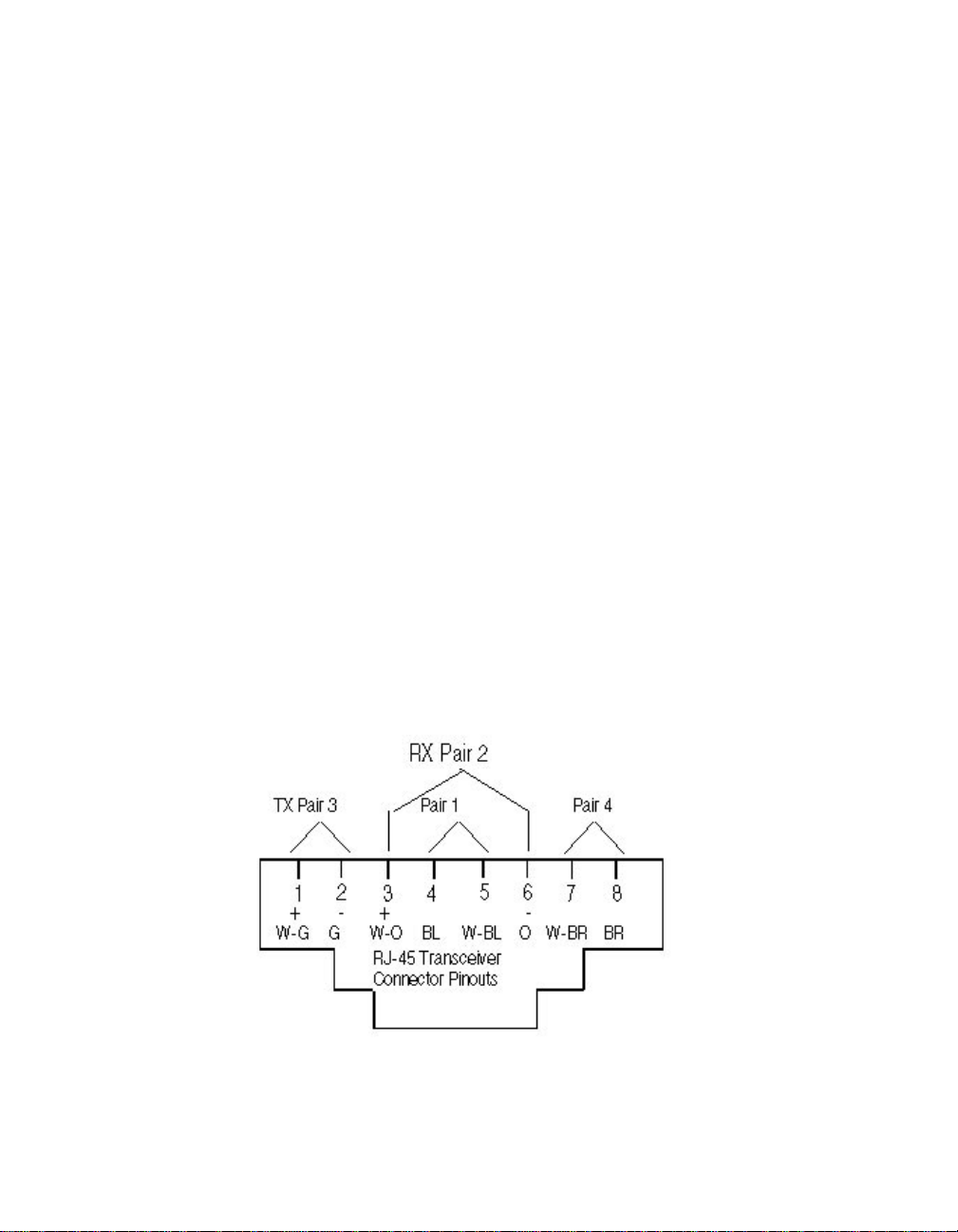
This section is divided into the following parts:
❑ Twiste d Pa ir C on ne ct or s
❑ Twiste d Pa ir C ab les
Twisted Pair Connectors
Uset the IEEE 80 2.3 10BASE-T standard for RJ-45 pinouts as described
below. 10BASE-T uses 2 of the 4 pairs of wire: pins 1 and 2 and pins 3 and
6. If the pairs are not configured this way, the connection wil l not work
properly. Level 3 or higher cable should have the fo llowing pin pairi ngs:
❑ pins 4 and 5 are pair 1
❑ pins 3 and 6 are pair 2
❑ pins 1 and 2 are pair 3
❑ pins 7 and 8 are pair 4
Refer to Figure A-1 for an example of the recommended TIA-568A wiring
standard for an RJ-45 connector.
Figure A-2. RJ-45 Connector Pinouts
Specifications A - 7
Page 96

Some installations may have 50-pin Telco connectors at the wiring closet.
We recommend using a patch panel that converts from 50-pin to RJ45-type
connectors. This allows direct connection to the Security Module in your
ONline System Concentrator.
Twisted Pair Cables
The cables that are supported must meet the following qualifications:
❑ Level 3 or hi gher
❑ 22 or 24 gauge tw isted pair ca ble
❑ 85 to 115 ohm impedance
❑ minimum of 2 pairs
A pair is usually a solid color wire twisted with a striped wire with the same
color.
A - 8 ONline 10BASE-T Security Module Installation and Operation Guide
Page 97

B
Technical Support
3Com prov ides easy access to technical support information through a
variety of services. This appendix describes the following services:
❑ On-line Technical Support
❑ Support from Your Network Supplier
❑ Support from 3Com
❑ Returning Products for Repair
❑ Accessing the 3Com MIB
❑ 3Com Technical Pu blications
On-line Technical Support
3Com offers worldwide product suppo rt through the followin g on-line
systems:
❑ Email Technical Service
❑ World Wide Web Site
Technical Support B - 1
Page 98

Email Technical Support
You can contact the Integrated Systems Division (formerly Chipcom) on the
Internet for technical supp ort using the e-mail address
techsupp@chipcom.com.
World Wide Web Site
You can ac cess the latest networking informatio n on the 3Com World
Wide Web site by entering our URL into your Internet browser:
http://www.3Com.com/
This service features news and information about 3Com products,
customer serv ic e and support, the 3Com latest news releases, selected
articles from 3TE CH™, the 3Com award-winnin g technical journal, and
more.
You can contact the Integrated Systems Division on the World Wide Web
by entering our URL into your Internet browser:
http://www.chipcom.com/
There are li nks between both WWW pages to view information from all
3Com divisions.
Support from Your Network Supplier
If additional assistance is req uired, contact your network supplier. Many
suppliers are authorized 3Com service partners who are qualified to provide
a variety of services, including network planning, installation, hardware
maintenance, appli cation training, and su pport services.
B - 2 ONline 10BASE-T Security Module Installation and Operation Guide
Page 99

When you contact your network supplier for assistance, have the following
information ready:
❑ Diagnostic error messages
❑ A list of sys tem hardware and software, including revision levels
❑ Details about recent configuration changes, if applicable
If you are unable to contact your network supplier, see the following
section on how to contact 3Com .
Support from 3Com
If you are unable to receive support from your network supplier, technical
support contracts are a vailable from 3Com.
For direct access to customer service for Integrated Systems Division
products in:
❑ U.S.A . and Canada - call (800) 724-2447
❑ Asia Pacific - call (508) 787-5151
❑ Europe - refer to the table below. For European countries not listed,
call 31 30 60 299 00
Country Telephone Number Country Telephone Num ber
Belgium 0800 71429 Netherlands 06 0227788
Denmark 800 17309 Norway 800 11376
Finland 0800 113153 Spain 900 983125
France 05 917959 Sweden 020 7 95482
Germany 0130 82 1502 U.K. 0800 96619 7
Ireland 1 800 553117 U.S. 800 876-3266
Italy 1678 79489
Technical Support B - 3
Page 100

For access to customer service for all 3Com products, call (800) 876-3266.
You can also contact the Integrated Systems Div ision (ISD) on the Internet
by using the e-mail address techsupp@c hipcom.com.
Returning Produc ts for R epair
A product sent directly to 3Com for repair must first be assig ned a Return
Materials Authorization (RMA) number. A product sent to 3Com without
an RMA number will be returned to the sender unopened, at the sender’s
expense.
To obtain an RMA number for Integrated Systems Division products
(formerly Chipcom ), use the following numbers .
Country Telephon e Number Fax Number
U.S. and Canad a (800) 724-2447 (508) 787-3400
Europe (44) (1442) 275860 No Fax
Asia Pacific (508) 787-5296 (508) 787-3400
Accessing the 3Com MIB
The 3Com Management Information Base (MIB) for the Integrated Systems
Division desc ribes commands that enable you to manage 3Com
SNMP-based products. The MIB is available over the Internet on an
anonymous FTP server. Updates to these MIBs are released as new 3Com
products are introduced.
To access Internet vers ions:
1. FTP to ftp.chipcom.com (151.104.9.65).
2. Enter the login name anonymous.
B - 4 ONline 10BASE-T Security Module Installation and Operation Guide
 Loading...