

Page 1

®
ONline Ethernet 10BASE-FB
Module Installation and
Operation Guide
Document Number 17-00328-5
Printed February 1996
Model Number: 510M-FBP
5102M-FBP
5104M-FB1
3Com Co rporation
118 Turnpike Road
Southborough, MA 01772-1886
U.S.A.
(508) 460-8900
FAX (508) 460-8950
Page 2

Federal Communications Commission
Notice
This equipment has been tested and found to comply with the
limits for a Class A digital device, pursuant to Part 15 of the FCC
Rules. These limits are designed to provide reasonable protection
against harmful interference when the equipment is operated in a
commercial environment. This equipment generates, uses, and can
radiate radio frequency energy and, if not installed and used in
accordance with the instruction manual, may cause harmful
interference to radio communications. Operation of this equipment
in a residential area is likely to cause harmful interference, in which
case you must correct the interference at your own expense.
Canadian Emissions Requirements
This Class A digital apparatus meets all requirements of the
Canadian Interference-Causing Equipment Regulations.
Cet appareil numérique de la classe A respecte toutes les exigences
du Règlement sur le matériel brouilleur du Canada.
VDE Class B Compliance
Hiermit wird bescheinigt, dass der 510M-FBP in Üebereinstimmung
mit den Bestimmungen der Vfg 243/1991 funkentstöert ist.
Der Deutschen Bundespost wurde das Inverkehrbringen dieses
Geraetes angezeigt und die Berechtigung zur Üeberprüefung der
Serie auf Einhaltung der Bestimmungen eingeräeumt.
Einhaltung mit betreffenden Bestimmugen kommt darauf an, dass
geschirmte Ausfuehrungen gebraucht werden. Fuer die
Beschaffung richtiger Ausfuehrungen ist der Betreiber
verantwortlich.
This is to certify that the 510M-FBP is shielded against radio
interference in accordance with the provisions of Vfg 243/1991.
The German Postal Services have been advised that this equipment
is being placed on the market and that they have been given the
right to inspect the series for compliance with regulations.
Compliance with applicable regulations depends on the use of
shielded cables. The user is responsible for procuring the
appropriate cables.
EN55022/CISPR22 Compliance
This equipment conforms to the Class A emissions limits for a
digital device as defined by EN55022 (CISPR22).
VCCI Class 1 Compliance
This equipment is in the 1st Class category (information equipment
to be used in commercial or industrial areas) and conforms to the
standards set by the Voluntary Control Council for Interference by
Information Technology Equipment aimed at preventing radio
interference in commercial or industrial areas.
Consequently, when the equipment is used in a residential area or
in an adjacent area, radio interference may be caused to radio and
TV receivers, and so on.
Read the instructions for correc t handling .
Fiber Cable Classificat ion Notice
Use this equipment only with fiber cable classified by Underwriters
Laboratories as to fire and smoke characteristics in accordance
with Sectio n 770-2(b) and Section 725-2(b) of the National
Electrical Code.
UK General Approval Statement
The ONcore Switching Hub, ONline System Concentrator, and
ONsemble StackSystem Hub are manufactured to the International
Safety Standard EN 60950 and are approved in the UK under the
General Approval Number NS/G/12345/J/100003 for indirect
connection to the public telecomm unication network.
Disclaimer
The information in this document is subject to change without
notice and should not be construed as a commitment by 3Com
Corporation. 3Com Corporation assumes no responsibility for any
errors that may appear in this document.
Copyright State me nt
©
1996 by 3Com Corporation. Printed in U.S.A. All rights reserved.
The information contained herein is the exclusive and confidential
property of 3Com Corporation. No part of this manual may be
disclosed or reproduced in whole or in part without permission
from 3Com Corporation.
Tradema rks and Paten ts
Because of the nature of this material, numerous hardware and
software products are mentioned by name. In most, if not all
cases, these product names are cla imed as trademarks by the
companies that manufacture the products. It is not the intent of
3Com Corporation to claim these names or trademar ks as its own.
3Com, Artel, Boundary Routing, CardBoard, CardFacts, Galactica,
EtherDisk, EtherLink, EtherLink II, EtherLink Plus, LANplex,
LANsentry, LinkBuilder, NETBuilder, NETBuilder II, NetFacts,
ONcore, ONsemble, ORnet, Parallel Tasking, SmartAgent,
StarBridge, TokenLink, TokenLink Plus, TriChannel, and ViewBuilder
are registered trademarks of 3Com Corporation.
3Com Laser Library, 3Com OpenHub, 3TECH, FDDILink, FMS,
G-Man, MultiProbe, NetProbe, OnDeck, ONdemand, ONline,
PowerRing, StackJack, StackSystem, StackWay, Star-Tek,
SwitchCentral, and Transcend are trademarks of 3Com
Corporation.
3ComFacts and Ask3Com are service marks of 3Com Corporation.
ii ONline Ethernet 10BASE-FB Module Installation and Operation Guide
Page 3

The 3Com Multichannel Architecture Communications System is
registered under U.S. Patent Number 5,301,303.
AT&T is a registered trademark of American Telephone and
Telegraph Company.
Banyan and VINES are registered trademarks of Banyan
Systems Inc.
CompuServe is a registered trademark of CompuServe, Inc.
ProComm is a registered trademark of DATASTORM
TECHNOLOGIES, INC.
DATASTORM is a trademark of DATASTORM TECHNOLOGIES, INC.
DEC, DECnet, DELNI, POLYCENTER, VAX, VT100, VT220, and the
Digital logo are trademarks of Digital Equipment Corporation.
Hayes is a registered trademark of Hayes Microcomputer Products.
OpenView is a registered trademark of Hewlett-Packard Company.
Intel is a registered trademark of Intel Corporation.
AIX, IBM, and NetView are registered trademarks of International
Business Machines Corporation.
Microsoft and MS-DOS are registered trademar ks of Microsoft
Corp.
Windows is a trademark of Microsoft Corp.
OSF and OSF/Motif are registered trademarks of Open Software
Foundation, Inc.
V30 is a trademark of NEC Corporation.
NetWare and Novell are registered trademarks of Novell,
Incorporated.
IPX is a trademark of Novell, Incorporated.
Retix is a registered trademark of Retix.
ROUTERXchange is a trademark of Retix.
Solaris, SPARCengine, Sun, Sun Microsystems, and SunSoft are
registered trademarks of Sun Microsystems, Inc.
ONC, OpenWindows, SunNet Manager, and SunOS are trademarks
of Sun Microsystems, Inc.
SPARCstation and SPARCompiler are licensed exclusively to Sun
Microsystems, Inc.
OPEN LOOK is a registered trademark of Unix System Laboratories,
Inc.
UNIX is a registered trademark in the United States and other
countries, licensed exclusively through X/Open Company, Ltd.
3Com registered trademarks are registered in the United States,
and may or may not be registered in other countries. Other brand
and product names may be registered trademarks or trademarks of
their respective holders.
Restricted Rights
Use, duplication, or disclosure by the Government is subject to
restrictions as set forth in subparagraph (c)(1) (ii) of the Rights in
Technical Data and Computer Software clause at
DFARS 252.227-7013.
Printed on recycled paper.
ONline Ethernet 10BASE-FB Module Installation and Operation Guide iii
Page 4

iv ONline Ethernet 10BASE-FB Module Installation and Operation Guide
Page 5

Contents
How to Use This Guide
Audience . . . . . . . . . . . . . . . . . . . . . . . . . . . . . . . . . . . . . . . . . . . . . . . . . . xiii
Structure of This Guide . . . . . . . . . . . . . . . . . . . . . . . . . . . . . . . . . . . . . . . . xiv
Docume nt Conventions . . . . . . . . . . . . . . . . . . . . . . . . . . . . . . . . . . . . . . . xv
Related Documents . . . . . . . . . . . . . . . . . . . . . . . . . . . . . . . . . . . . . . . . . . xvi
3Com Doc uments . . . . . . . . . . . . . . . . . . . . . . . . . . . . . . . . . . . . . . . . xvi
Reference Documents . . . . . . . . . . . . . . . . . . . . . . . . . . . . . . . . . . . . .xvii
Chapter 1 — Introduction
10BAS E-FB Modu le Descri ptions . . . . . . . . . . . . . . . . . . . . . . . . . . . . . . . . .1-2
10BAS E-FB Comp liance . . . . . . . . . . . . . . . . . . . . . . . . . . . . . . . . . . . . . . . .1-4
Theory of Operation . . . . . . . . . . . . . . . . . . . . . . . . . . . . . . . . . . . . . . . . . .1-4
Compatibility With Other Ethernet Fiber Products . . . . . . . . . . . . . . . . . . . .1-6
Chapter 2 — Designing and Expanding the Network
Understand ing the General Rules . . . . . . . . . . . . . . . . . . . . . . . . . . . . . . . .2-2
Rules for Configuring a Network . . . . . . . . . . . . . . . . . . . . . . . . . . . . .2-2
Equivalent F iber Dist ances . . . . . . . . . . . . . . . . . . . . . . . . . . . . . . . . . .2-5
Determining Maximum Fiber Link Distances . . . . . . . . . . . . . . . . . . . . . . . .2-6
Calc ulating Ma ximum Link Distance . . . . . . . . . . . . . . . . . . . . . . . . . . .2-7
Determining Link Budget . . . . . . . . . . . . . . . . . . . . . . . . . . . . . . . . . . .2-7
Attenuation . . . . . . . . . . . . . . . . . . . . . . . . . . . . . . . . . . . . . . . . .2-10
Splicing . . . . . . . . . . . . . . . . . . . . . . . . . . . . . . . . . . . . . . . . . . . .2-10
Opti cal Fiber Loss . . . . . . . . . . . . . . . . . . . . . . . . . . . . . . . . . . . . .2-11
Maximum Link Distance C alculation . . . . . . . . . . . . . . . . . . . . . . .2-12
Choosing a Network Backbone Cabling Structure . . . . . . . . . . . . . . . . . . .2-14
Star C o nfiguration . . . . . . . . . . . . . . . . . . . . . . . . . . . . . . . . . . . . . . .2-15
Serial Configuration . . . . . . . . . . . . . . . . . . . . . . . . . . . . . . . . . . . . . .2-16
10BAS E-FB Modu le Confi gurati ons . . . . . . . . . . . . . . . . . . . . . . . . . . . . . .2-17
Fiber Backbone, Fiber-to-the-Desk . . . . . . . . . . . . . . . . . . . . . . . . . . . .2-17
ONline Ethernet 10BASE-FB Module Installation and Operation Guide v
Page 6

Networ k Distance Calculatio n Examples . . . . . . . . . . . . . . . . . . . .2-19
Fiber Backbone, Unshielded Twisted Pair to-the-Desk . . . . . . . . . . . . .2-22
Fibe r Backbone, Coaxial Connection . . . . . . . . . . . . . . . . . . . . . . . . . .2-24
Fault-Tolerant Configurations . . . . . . . . . . . . . . . . . . . . . . . . . . . . . . . . . .2-26
Configuring Ports for Fault Tolerance . . . . . . . . . . . . . . . . . . . . . . . . .2-26
Setting Redundancy . . . . . . . . . . . . . . . . . . . . . . . . . . . . . . . . . . .2-27
Implementing Total Backbone Fault Toleranc e . . . . . . . . . . . . . . . . . .2-29
Chapter 3 — Installing and Operating the Module
Precautionary Procedures . . . . . . . . . . . . . . . . . . . . . . . . . . . . . . . . . . . . . .3-2
Unpacking Procedures . . . . . . . . . . . . . . . . . . . . . . . . . . . . . . . . . . . . . . . .3-3
Quick Installation . . . . . . . . . . . . . . . . . . . . . . . . . . . . . . . . . . . . . . . . . . . .3-4
Setting the Dip Switches . . . . . . . . . . . . . . . . . . . . . . . . . . . . . . . . . . . . . .3-5
Setting Dip Switch S1 . . . . . . . . . . . . . . . . . . . . . . . . . . . . . . . . . . . . . .3-7
Setting Dip Switch S2 . . . . . . . . . . . . . . . . . . . . . . . . . . . . . . . . . . . . . .3-9
Inst alling t he Module . . . . . . . . . . . . . . . . . . . . . . . . . . . . . . . . . . . . . . . .3-10
Configuring the Module . . . . . . . . . . . . . . . . . . . . . . . . . . . . . . . . . . . . . .3-13
Enabling Ports . . . . . . . . . . . . . . . . . . . . . . . . . . . . . . . . . . . . . . . . . .3-14
Selecting a Net work . . . . . . . . . . . . . . . . . . . . . . . . . . . . . . . . . . . . . .3-15
Enabling Port Redundancy . . . . . . . . . . . . . . . . . . . . . . . . . . . . . . . . .3-16
Enab ling Low Lig ht Warning . . . . . . . . . . . . . . . . . . . . . . . . . . . . . . . .3-17
Enab ling Optical Power . . . . . . . . . . . . . . . . . . . . . . . . . . . . . . . . . . .3-17
Savi ng Module Co nfigur ation . . . . . . . . . . . . . . . . . . . . . . . . . . . . . . .3-18
Showing Module Configuration . . . . . . . . . . . . . . . . . . . . . . . . . . . . . . . .3-18
Monitoring the Front Panel . . . . . . . . . . . . . . . . . . . . . . . . . . . . . . . . . . . .3-19
Verifying LED and Network Assignments . . . . . . . . . . . . . . . . . . . . . . . . .3-22
Chapter 4 — Troubleshooting
Troubleshooting Using the Port Activity LEDs . . . . . . . . . . . . . . . . . . . . . . .4-2
Troubleshooting Using the Port Status LEDs . . . . . . . . . . . . . . . . . . . . . . . .4-3
Technical Assistance . . . . . . . . . . . . . . . . . . . . . . . . . . . . . . . . . . . . . . . . . .4-7
vi ONline Ethernet 10BASE-FB Module Installation and Operation Guide
Page 7

Appendix A — Specifications
General Specifications . . . . . . . . . . . . . . . . . . . . . . . . . . . . . . . . . . . . . . . A-2
Opti cal Spec ificat ions . . . . . . . . . . . . . . . . . . . . . . . . . . . . . . . . . . . . . . . . A-3
Transmitter Specifications . . . . . . . . . . . . . . . . . . . . . . . . . . . . . . . . . . A-3
Receiver Specifications . . . . . . . . . . . . . . . . . . . . . . . . . . . . . . . . . . . . A-4
Supported Fiber Optic Cables . . . . . . . . . . . . . . . . . . . . . . . . . . . . . . . A-4
Fiber Optic Interface . . . . . . . . . . . . . . . . . . . . . . . . . . . . . . . . . . . . . . A-5
Power Requirements . . . . . . . . . . . . . . . . . . . . . . . . . . . . . . . . . . . . . . . . A-5
Environment al Specifications . . . . . . . . . . . . . . . . . . . . . . . . . . . . . . . . . . A-6
Mechanical Specificatio ns . . . . . . . . . . . . . . . . . . . . . . . . . . . . . . . . . . . . . A-6
3Com 10BASE-FB Network Products . . . . . . . . . . . . . . . . . . . . . . . . . . . . . A-6
10BASE-FB Cable and Connector Specifications . . . . . . . . . . . . . . . . . . . . . A-7
10BAS E-FB Cab les . . . . . . . . . . . . . . . . . . . . . . . . . . . . . . . . . . . . . . . A-7
10BASE-FB Connectors . . . . . . . . . . . . . . . . . . . . . . . . . . . . . . . . . . . . A-8
Connecting F iber Cables . . . . . . . . . . . . . . . . . . . . . . . . . . . . . . . . A-8
Appendix B — Technical Support
On-line Technical Support . . . . . . . . . . . . . . . . . . . . . . . . . . . . . . . . . . . . . .B-1
Email Technical Sup por t . . . . . . . . . . . . . . . . . . . . . . . . . . . . . . . . . . . .B-2
World Wide Web Sit e . . . . . . . . . . . . . . . . . . . . . . . . . . . . . . . . . . . . . .B-2
Support from Your Network Supplier . . . . . . . . . . . . . . . . . . . . . . . . . . . . .B-2
Support from 3Com . . . . . . . . . . . . . . . . . . . . . . . . . . . . . . . . . . . . . . . . . .B-3
Returning Products for Repair . . . . . . . . . . . . . . . . . . . . . . . . . . . . . . . . . . .B-4
Accessing the 3 Com MIB . . . . . . . . . . . . . . . . . . . . . . . . . . . . . . . . . . . . . .B-4
3Com Tec hnica l Publications . . . . . . . . . . . . . . . . . . . . . . . . . . . . . . . . . . . .B-5
Index
ONline Ethernet 10BASE-FB Module Installation and Operation Guide vii
Page 8

vii i ONline Ethernet 10BASE -FB Modu le Installatio n an d O peration Guide
Page 9

Figures
Figure 1-1. 10BAS E-FB Modu le Connec tions . . . . . . . . . . . . . . . . . . . . .1-5
Figure 2-1. 1700 Meter Fiber Link With Mechanical Splice . . . . . . . . .2-12
Figure 2-2. 2000 Meter Fiber Link Through Two Patch Panels . . . . . . .2-13
Figure 2-3. Star-Wiring Confi gurati on . . . . . . . . . . . . . . . . . . . . . . . . .2-15
Figure 2-4. Serial Configuration Using 10BASE-FB Modules . . . . . . . . .2-16
Figure 2-5. All-Fiber Network . . . . . . . . . . . . . . . . . . . . . . . . . . . . . . .2-18
Figure 2-6. Network With 3 Concentrators . . . . . . . . . . . . . . . . . . . . .2-19
Figure 2-7. Network Configured With 8 Concentrators . . . . . . . . . . . .2-20
Figure 2-8. Sample Configuration Distance Calculation . . . . . . . . . . . .2-23
Figure 2-9. Thin Etherne t Segment Co nnected to a n ONline
Figure 2-10. Redundant Fiber Backbone Configuration . . . . . . . . . . . . .2-28
Figure 2-11. Total Backbone Fault-Tolerant Configuration . . . . . . . . . . .2-30
Figure 2-12. Fiber Network With 3 Concentrators . . . . . . . . . . . . . . . .2-31
Figure 3-1. 10BASE-FB Module Dip Switch Locations . . . . . . . . . . . . . .3-6
Figure 3-2. Inst alling t he 10BASE -FB Modul e . . . . . . . . . . . . . . . . . . .3-11
Figure 3-3. 10BAS E-FB Modu le Connec tion . . . . . . . . . . . . . . . . . . . .3-12
Figure 3-4. 10BASE-FB Port-Switching Module Faceplate and
10BAS E-FB Module . . . . . . . . . . . . . . . . . . . . . . . . . . . . . .2-24
ONline System Concentrator . . . . . . . . . . . . . . . . . . . . . .3-20
ONline Ethernet 10BASE-FB Module Installation and Operation Guide ix
Page 10

x ONline Ethernet 10BASE-FB Module Installation and Operation Guide
Page 11

Tables
Table 1-1. 10BASE-FB Modu le Compatibility. . . . . . . . . . . . . . . . . . . . .1-6
Table 2-1. Basic Network Rules . . . . . . . . . . . . . . . . . . . . . . . . . . . . . .2-2
Table 2-2. Equivalent Fiber Distances of LAN Products . . . . . . . . . . . . .2-5
Table 2-3. ONline 10BASE-FB Module Optical Power Budget:
Normal Power. . . . . . . . . . . . . . . . . . . . . . . . . . . . . . . . . . .2-8
Table 2-4. ONline 10BASE-FB Module Optical Power Budget:
High Power. . . . . . . . . . . . . . . . . . . . . . . . . . . . . . . . . . . . .2-9
Table 2-5. 10BASE-FB Opt ical Power Budget . . . . . . . . . . . . . . . . . . . .2-9
Table 2-6. Connector and Splice Insertion Loss. . . . . . . . . . . . . . . . . .2-11
Table 2-7. Typical Fiber Loss Characteristics . . . . . . . . . . . . . . . . . . . .2-11
Table2-8. Fiber Equivalent Distances Between Transceivers . . . . . . . .2-21
Table 3-1. Quick Installation Procedures. . . . . . . . . . . . . . . . . . . . . . . .3-4
Table 3-2. Dip Switch S1 Settings for Switches 1 and 2 . . . . . . . . . . . .3-7
Table 3-3. Dip Switch S1 Settings for Switches 3 to 10. . . . . . . . . . . . .3-8
Table 3-4. Dip Switch S2 Settings . . . . . . . . . . . . . . . . . . . . . . . . . . . .3-9
Table 3-5. Interpreting the 10BASE-FB Module LEDs. . . . . . . . . . . . . .3-21
Table 3-6. Network Check Co des. . . . . . . . . . . . . . . . . . . . . . . . . . . .3-22
Table 4-1. Troubleshooting Using the Port Activity LEDs. . . . . . . . . . . .4-2
Table 4-2. Troubleshooting Using the Port Status LEDs. . . . . . . . . . . . .4-3
ONline Ethernet 10BASE-FB Module Installation and Operation Guide xi
Page 12

Page 13

This guide is designed to help you understand the features, indicators, and
installation procedures for the:
This guide also contains information on troubleshooting and diagnostics for
operation verification. In addition, a configuration section provides you
with network configuration information.
Audience
How to Use This Guide
❑ 3Com ONline™ Ethernet Port-Switching 10 BASE-FB Mod ules (Model
Numbers 5102M-FBP a nd 5104M-FBP)
❑ 3Com ONline™ Ethernet 10BASE-FB Module (Model Number
5104M-FB1)
This guide contain s instructions for installing the modules and maintaining
normal operation. It is intended for the following people at your site:
❑ Hardware installer
❑ System/Network manager
ONline Ethernet 10BASE-FB Module Installation and Operation Guide xiii
Page 14

Structure of This Guide
This guide contains the following chapters:
Chapter 1, Introduction – Introduces the principal features of the ONline
Ethernet Port-Switching 10BASE-FB Modules and the ONline Ethernet
10BASE-FB Module.
Chapter 2, Designing and Expanding the Network – Contains
configuration information to help you integrate the 10BASE-FB Modules
into your Ethernet network.
Chapt er 3, I n stall ing and Operating the Mod u le – Provides illustrated
procedures for installing the 10BASE-FB Modules into the ONline System
Concentrator and confi guring them for operation. This chapter also
provides a front panel view of the 10BASE-FB Modules showing ports, LEDs,
and dip switches.
Chapter 4, Troubleshooting – Provides help in isolating and correcting
problems that could arise during the installation process and during normal
operation.
Appendi x A, Spec ificat ions – Describes product dimensions, power
requirements, and ot her specifications for the modules.
Appendix B, Technical Support – Lists the various methods fo r
contacting the 3Com technical support organization and for accessing
other product support servi ces.
Index – Contains an alphabetical list of important terms and features
referenced throug hout this guide.
xiv ONline Ethernet 10BASE-FB Module Installation and Operation Guide
Page 15

Document Conve ntions
The following document convention s are used in thi s manuall:
Convention Indicates Example
Courier text User input In the Agent Information Form,
enter MIS in the New Contact
field.
System output After pressing the A pply
button, the sy stem displays
the message
Transmi tt in g da ta .
Bold command
string
Text in angled
brackets
Capitalized text in
plain brackets
Italics Text emphasis,
Path names Before you begin, read the
User-substituted
identifiers
Keyboard entry
by the user
docu me nt title s
readme.txt file located in
/usr/snm/agents.
In the command above,
substitute <rem_name> with
the name of the remote
machine.
Type your password and press
[ENTER].
Ensure that you press the Apply
button after you add the new
search parameters.
ONline Ethernet 10BASE-FB Module Installation and Operation Guide xv
Page 16

Convention Indicates Example
Note: A Note. The
Caution: A Caution. A
Warning: A Warning. A
Related Docu me nts
This section provides information on supporting documentation, including:
❑ 3Com Documents
information is
important
condition may
damage
software or
hardware
condition may
threaten
personal safety
Note: Use STP lobe
cables for yo ur s yste m.
Caution: Do not put
your installation
diskettes on a
magnetic surface.
This may damage the
diskettes.
Warning: Wear eye
protec tion when
performing these
maintenance
procedures.
❑ Reference Documents
3Com Documents
The following docum ents provide additional information on 3Com
products:
17-Slot ONline System Concentrator Installation and Operation
Guide – Explains how to install, operate, and manage the 3Com ONline
17-Slot Syste m Concentrator (Models 5017C-LS and 5017C with load
sharing).
xvi ONline Ethernet 10BASE-FB Module Installation and Operation Guide
Page 17

6-Slot ONline System Concentrator Installation and Operation
Guide – Explains how to install, operate, and manage the 3Com ONline
6-Slot System Concentrator.
ONline Ethernet Management Module Installation and Operation Guide –
Describes h ow to install the ONline Ethernet Management Mo dule in the
ONline System Concentrator and explains the LEDs on the module
faceplate. This guide also provides instructions for connecting a terminal to
the module and describes the management commands necessary to
perform man ag ement tasks on the concentrator and on remote devices.
ONline Management Commands Guide – Provides an a lphabetized
reference resource describing all ONline management commands.
For a complete list of 3Com documents, contact your 3Com representative.
Reference Documents
The following documents supply related background information:
Case, J., Fedor, M., Scoffstall, M., and J. D avin, The Simple Network
Management Protocol, RFC 1157, University of Tennessee at Knoxville,
Performan ce Systems International and the MIT Laboratory for Computer
Science, May 1990.
Rose, M., and K. McCloghrie, Structure and Identification of
Management Informat ion for TCP/IP-based Internets, RFC 1155,
Performance Systems International an d Hughes LAN Systems, May 19 90.
ONline Ethernet 10BASE-FB Module Installation and Operation Guide xvii
Page 18

Page 19

1
This chapter introduces you to the:
The modules are referred throughout this guide as the 10BASE-FB Modules.
Information in this guide refers to all three 10BASE-FB Modules listed above.
Differences between the m odules are noted where a pplicable.
This chapter contains the following sections:
Introduction
❑ 3Com ONline™ Ethernet Port-Switching 10 BASE-FB Mod ules
(5102M-FBP and 5104M-FBP)
❑ 3Com ONline™ Ethernet 10BASE-FB Module (5104M-FB 1)
❑ 10BASE-FB Module Des criptions
❑ 10BASE-FB Compliance
❑ 10BASE-FB Theory of Operation
❑ Compatibility With Other Ethernet Fiber Products
Introduction 1 - 1
Page 20

10BASE-FB Module Descriptions
The ONline Ethernet Port-Switching 10BASE-FB Module is a 2- or 4-port,
Ethernet fiber module designed for 3Com ONline System Concentrators.
The ONline Ethernet 10BAS E-FB Module is a 4-port, Ethernet fiber module
also designed for 3Com ONli ne System Concentrato rs.
The ONline Ethernet Port-Switching 10BASE-FB Module (Model Number
5104M-FBP) is functionally identical to the ONline Ethernet 10BA SE-FB
Modul e ( Model Numb er 5104M-F B1 ) except for the Port-Switching
Module's ability to set each port to an independent backplane n etwork in
the concentrator.
The 5104M-FB1 is module-switching only. You can update the 10BASE-FB
Module to a port-switching module by installing the ONline Ethernet
10BASE-FB Upgrade Kit.
The 10BA SE-FB Modules provide:
❑ Fiber backbone connectivity for Ethernet local area networks
❑ Direct fiber to-the-desk connectivity
You can directly connect the 10BASE-FB Modules to any other ONline fiber
module as well as all of the products in the 3Com 10BASE-FB family,
including the:
❑ 3Com 10BASE-FB Star Coupler
❑ 3Com 10BASE-FB Fiber Transceiver
❑ 3Com Fault-Tolerant 10BASE-FB Transceiver
The 10BASE-FB Modules:
❑ Provide up to 4.0 kilometers distance between any two concentrators
❑ Support network diameters up to 4.2 kilometers
❑ Contain built-in link redundancy for fault tolerance
1 - 2 ONline Ethernet 10BASE-FB Module Installation and Operation Guide
Page 21

❑ Include diagnostics for troubleshooting
❑ Provide 1 0 Mbps performance wi th 100 percent collision detectio n
using CSMA/CD
❑ Support 50, 62.5, 85, and 100 µm fiber cable
❑ Are shipped with either ST, SMA, or FC-type connectors
Other benefits of the 10BASE-FB Modules i nclude:
❑ 3Com TriChannel Architecture - The 10BASE-FB Modules operate in
an ONline System Concentrator with all ONline modules, including
Token Ri ng and FDDI.
❑ Slot Independence - You can install modules into any available slot
in the ONline Concentrator. This flexibility eliminates the need to shut
down the network and rearrange the existing configuration of the
concentrator when you install new modules into the concentrator.
❑ “Hot Sw ap” Capability - You can install or remove modules from
the ONline System Concentrator when it is powered up without
affecting the operation of any other modules in the concentrator.
❑ Independent Networks - You can assign each module to any of
three indep endent Ethernet networks.
❑ Management Support - You can manage the module through the
3Com ONdemand™ Network Control System. You may also manage
the 10BASE-FB modules using terminal management through an
ONline network management modul e.
❑ Compliance - The 10BASE-FB Modules comply with the IEEE
10BASE-FB fiber standard to provide interoperability with other
standards-based products.
Introduction 1 - 3
Page 22

10BASE-FB Compliance
The ONline Ethernet Port-Swi tching 10BAS E-FB Modules an d the ONline
Ethernet 10BASE-FB Module a re fully compliant with the IEEE 10BASE-FB
fiber standard. The IEEE ratification of the 10BASE-FB standard validates
synchronous fiber Ethernet as the choice for backbon e links. Synchronous
technology provides robust transmission for fiber Ethernet backbones.
Compliance with the 10BASE-FB standard allows 3C om fiber modules to be
compatible with:
❑ Industry 10BASE-FB -compliant products
❑ Existing 3 Com 10BASE-FB techno lo gy
3Com 10BASE-FB Modules implement Ethernet/IEEE 802.3 physical l ayer
function ality on a fiber optic med ium. Full in terconnection of all dev ices
that comply with Ethernet V2.0 o r IEEE 802.3 spec ifications are p rov ided,
including:
❑ Minicomputers
❑ Engineering workstations
❑ PC networking servers
❑ Bridges
Theory of Operatio n
The 10BA SE-FB Modules serve mainly as network backbone links. Network
backbone links connect concentrators together. You may also use the
10BASE- FB Modules to connect directly to devices usin g the:
❑ 3Com 5101T-FB Transceiver
❑ 3Com 5102T-FBFT Faul t-Tolerant Tra nsceiver
1 - 4 ONline Ethernet 10BASE-FB Module Installation and Operation Guide
Page 23
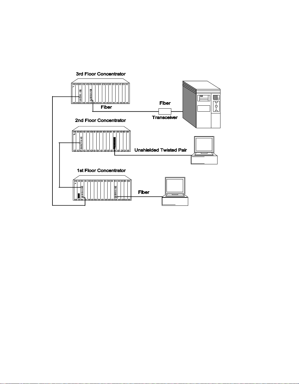
Figure 1-1 illustrates a configuration using fiber transceivers and the
10BASE-FB Modules to connect concentrato rs and devices
.
Figure 1-1. 10BASE-FB Module Connections
Introduction 1 - 5
Page 24

Compatibility With Other Ethernet Fiber Products
The 10BASE-FB Modules are compatible with the 3Com products outlined in
Table 1-1.
Table 1-1. 10BASE-FB Module Compatibility
3Com Product Part Numb er
10BASE-FB Star Coupler 9308S-FB
10BASE-FB Transceiver 5101T-FB
Fault-Tolerant 10BASE-FB Transceiver 5102T-FBFT
From the backplane interface, you can also connect the 10BASE-FB Modules
to other Ethernet modules on the same network.
Caution: The 10BASE-FB Modules are not compatible with the
ONline Ethernet 1 0BASE-FL Module (Model N umber
5104M-FL1). The 4-port10BASE-FL Module faceplate is
simi lar t o the 1 0BAS E-FB M odu les, bu t the two mo dule s
cannot communicate.
1 - 6 ONline Ethernet 10BASE-FB Module Installation and Operation Guide
Page 25

2
Designing and Expanding t he Network
This chapter contains configuration information to help you design your
network . It describes how to configure networks using the ONline S ystem
Concentrator and the ONline 10BASE-FB Modules. I t also provides
examples of network cabling structures and Ethernet network cabling
solutions.
This chapter contains the following sections:
❑ Understanding the General Rules
❑ Determining Maximum Fiber Link Dis tances
❑ Choosing a Network Backbone Cabling Structure
❑ 10BASE-FB Module Configurations
❑ Fault-To lerant Configurations
Note: To ensure proper operation of yo ur network, install all
equipment using only approved cables. Refer to Appendix
A for information on cable requirements.
Designing and Expanding the Network 2 - 1
Page 26

Understanding the General Rule s
This section describes general rules for configuring an Ethernet network
using fiber as the backbone medium. It also provides rules to ensure that
your network configuration conforms to distance limitations imposed by
Ethernet and networking equipment. Use these guidelines for building
your network.
Refer to the sections that follow for specific rules for:
❑ Determining maxi mum 10BASE-FB fiber link distances
❑ Connecting various horizontal media types (10BASE-FB, twisted pair)
to a 10BASE-FB backbone
❑ Examples of recommended fault-tolerant configurations
Rules for Configuring a Network
This section outlines the netw ork rules and reco mmendations for building
an Ethernet n etwork. For more hardware-specific information on the
10BASE-FB, refer to Appendix A.
Table 2-1. Basic Netw ork Rules
Rule Definition Recommen dations/No tes
1 Use 10BASE-FB as the
backbone mediu m.
2 Wire the bac kbone in a
star topology to isolate
faults.
2 - 2 ONline Ethernet 10BASE-FB Module Installation and Operation Guide
Use 62.5 micron cable to
conform with the IEEE 10BASE-F
and ANSI FDDI standards.
Use ST-type connectors.
Lay extra fiber cables. The extra
cost is small and you will need
them as your network grows.
Page 27

Table 2-1. Basic Network Rules (Continued)
Rule Definition Recommendations/N otes
2
(con’t)
3 Do not exceed the
4 Certain LAN products
Wire the bac kbone in a
star topology to isolate
faults.
maximum Fiber Ethernet
network diameter of
4200 meters of fiber
cable.
on the netwo rk shrink
the maximum Fiber
Ethernet network
diameter to less than
4200 meters.
The star topology confo rms to
FDDI wiring . Run at least two
fiber stran ds to each backbone
connection.
The 4200 meters is the
maximum distan ce between
any two transceivers on the
network.
The 4200 meters does not
include the transceiver cable
that connects a device with an
external transceiver.
Transceiver cable can extend up
to 50 meters. Thus, total
network diameter can be as
much as 4300 meters (4200 m +
2 * 50 m) between any two
modes.
Each microsecond delay
through a device on the
network shrinks the network
diameter by approximately 200
meters of fiber cable. This
reduction is known as
equivalent distance. Table 2-2
lists the equivalent fiber
distances for 3Com ONline LAN
products.
Designing and Expanding the Network 2 - 3
Page 28

Table 2-1. Basic Network Rules (Continued)
Rule Definition Recommendations/N otes
5 Assume that one meter
of coaxi al or twisted
pair cable is equal to
one meter of fiber
cable.
6 Verify that the
10BASE-FB link
distances do not
exceed the limits
imposed by the optical
power budge t .
7 When in doubt, use a
bridge.
This is a conservative
equivalence. One meter of fiber
is actually equal to 1.1 meters of
coaxial. For simplicity, assume
one meter.
In general, on 62.5 cable, use
up to 4000 meters
point-to-point using the
10BASE-FB Modules. If you
have poor quality cable or
numberous patch panels, you
may have to sacrifice some
distance.
Some older Ethernet fiber optic
products are less powerful than
ONline 10BASE-FB Module
optics. When connecting to
these pro ducts, remember that
they determine the maximum
point-to-point distance.
If you are not certain you have
exceeded acceptable netw ork
distances, use a bridge to
extend the n etwork.
2 - 4 ONline Ethernet 10BASE-FB Module Installation and Operation Guide
Page 29

Equivalent Fiber Distances
Equivalent fiber distance is the sum of both t he incoming and outgoing
module port signals. Different products, however, have different
equivalent distances. Table 2-2 lists the equivalent fiber distance of 3Com
ONline LAN products.
Table 2-2. Equivalent Fiber Distances of LAN Products
LAN Produc t
ONline Ethernet 10BASE-FB Modules
(5104M-FB1, 5102M-FBP, 5104M-FBP)
Incoming signal to fiber port 140
Outgoing sign al from fibe r por t 50
ONline Ethern et 10BASE-FL Module (5104M-FL1) 560
Incoming signal to fiber port 330
Outgoing signal from fibe r por t 230
ONline Ethernet 10BASE-T Module (5108M-TP) 585
Incoming si gnal to TP port 420
Outgoing signal from TP p ort 165
ONline Ethernet 50-Pin Module
(5112M-TPL, 5112M-TPPL)
Incoming si gnal to TP port 420
Equivalent Fib er
Distance (meters)
190
585
Outgoing signal from TP p ort 165
ONline Ethernet 24-Port Module (5124M-TPCL,) 585
Incoming si gnal to TP port 420
Outgoing signal from TP port 165
Designing and Expanding the Network 2 - 5
Page 30

Table 2-2. Equivalent Fiber Distances of LAN Products (Continued)
LAN Produc t
ONline Ethernet Repeater Module (5102M-AUIF) 800
Incoming si gnal to AUI port 600
Outgoing signal from AUI port 200
ONline Ethernet BNC Module (5106M-BNC) 900
Incoming signal to BNC port 450
Outgoing signal from BNC port 450
ONline Ethernet Transceiver Module (5103M-AUIM) 0
3Com 10BASE-FB Star Cou pler (9308S-FB) 180
10BASE-FB S tar Coupler (9314S) 180
IEEE Repeater 800
Equivalent Fib er
Distance (meters)
Determining Maxim um F iber Link Dis tanc e s
This section describes how to calculate the maximum allowable link
distances between two fiber ports. To do this, you must kn ow the
following information:
❑ 10BASE-FB optical power budg et
❑ Fiber cable diameter (for example, 50 micron, 62.5 micron)
❑ Fiber cable light loss/km (for example, 3 dB loss/km)
❑ Number of patch panel connections and link splices
2 - 6 ONline Ethernet 10BASE-FB Module Installation and Operation Guide
Page 31

The fo llowin g tables as sist you in obtaining this i nformation:
❑ Table 2-3 - Lists the optical power budget for the 10BASE-FB Module
❑ Table 2-6 - List typical losses for connector and splice insertion loss
❑ Table 2-7 - Lists typical losses for various fiber cables
Calculating Maximum Link Distance
To calculate the maximum link distance allowed:
1. Determ ine the optical power budget for the 10BASE-FB
port (Table 2-3).
2. Subtract the optical power loss due to patch panels and splices
(Table 2-6) from the optical power budget for the 10BASE-FB p ort.
3. Subtract the dB loss/km rating of the fiber cable (Table 2-7) from the
remainder of step 2. If the result is greater than 0, the link distance is
valid.
4. If the device connecting to the 10BASE-FB Module does not have the
same optical budget as the 10BASE-FB Module, you must also
calculate the maximum link distance for the connecting device.
Determining Link Budget
To ensure link integrity, you should plan for worst case losses through the
end-to-end optical connection. The optical power budget represents a
worst case that assumes the transmitter is transmitting at the low end of its
range. When possible, 3Com recommends using Normal power.
Designing and Expanding the Network 2 - 7
Page 32

Table 2-3 provides the transmit optical power ranges and required receiver
optical power budget levels fo r the 10BASE-FB Modules.
Table 2-3. ONline 10BASE-FB Module Optical Power B udget:
Normal Power
Cable
Size
Used
(micron)
50/125
NA
0.20
62.5/125
NA
0.275
85/125
NA
0.29
100/140
NA
0.29
Transmit
Power
Range
(dBm)
-21.5 ±
3.0
-17.0 ± 3.0 -8.0 to
-14.0 ±
3.0
-11.5 ± 3.0 -8.0 to
Receive
Power
Range
(dBm)
-8.0 to
-30.0
-30.0
-8.0 to
-30.0
-30.0
Link
Optical
Powe r
Budget
(dB)
5.5 None None
10.0 None None
13.0 None >3.0
15.5 None >5.5
Loss
Required
(dB)
(ONline to
ONline)
Link Loss
Required
(dB)
(ONline to
10BASE-FB)
Table 2-4 provides 10BASE-FB Module optical power budget values for high
power.
2 - 8 ONline Ethernet 10BASE-FB Module Installation and Operation Guide
Page 33

Table 2-5 provides information on the 10BASE-FB-specific optical power
budget.
Table 2-4. ONline 10BASE-FB Module Optical Power B udget:
High Power
Cable
Size
Used
(micron)
50/125
NA 0.20
62.5/125
NA
0.275
85/125
NA 0.29
100/140
NA 0.29
Table 2-5. 10BASE-FB Optical Power Budget
Cable Size Used
(micron)
Transmit
Power
(dBm)
-14.25 ±
2.25
-10.0 ±
2.25
-7.0 ±
2.25
-4.5 ±
2.25
Receive
Power
(dBm)
-8.0 to
-30.0
-8.0 to
-30.0
-8.0 to
-30.0
-8.0 to
-30.0
Transmit
Power
(dBm)
Opti cal
Power
Budget
(dB)
13.5 None >2.0
17.75 >0.25 >6.25
20.75 >3.25 >9.25
23.25 >5.75 >11.75
Receive
Power
(dBm)
Link Loss
Required
(dB)
(ONline to
ONline)
Budget (dB)
Link Loss
Required
(dB)
(ONline to
10BASE- F
B)
Optical
Power
50/125 (N A 0.20) -20.0 ± 1.0 -14.0 t o 29.0 8.0
62.5/125(NA 0.275) -15.1 ± 1.0 -14.0 to 29.0 12.9
85/125 (N A 0.29) -13.1 ± 1.0 -14.0 to 29.0 14.9
100/140 (NA 0.29) -11.6 ± 1.0 -14.0 t o 29.0 16.4
Designing and Expanding the Network 2 - 9
Page 34

Attenuation
It is possible for receivers to receive to o much light when:
❑ Using 85/125 and 100/140 micron fiber cables
❑ Ports are close together on a link
Receivers can also receive too much light on 62.5 micron fiber and High
power on the 1 0BASE-FB Modules when:
❑ Connecting to an 10BASE-FB product (6.25 dB loss required)
❑ Connecting to another 10BASE-FB Module ( .25 dB loss required)
In these two situations, switch the 10BASE-FB Module to Normal power.
In all of the cases listed above, some attenuation is required to prevent this
problem. This attenuation is covered by:
❑ A moderate link length
❑ The fiber optic connectors
Splicing
Many fiber op tic installations employ the use of patch panels to manage
expansion and topological changes. A typical patch panel consists of a set
of female to female bulkhead barrel connectors used to connect male fiber
connectors on b oth side s. Th e optical power loss through a p atch pane l
therefore includes two connectors and a bulkhead.
If a fiber optic cable breaks, the break is usually fixed by splicing the broken
ends together. Use one of the following types of splicing methods:
❑ Fusion – A fusion splice usually offers lower power loss, but the
fusion equipment is often bulky and costly.
❑ Mechanical – A mechanical splice can be conveniently used in the
field when a fusion splice is not available. If a repair is made, make
sure that the fiber cable still meets the power loss guidelines.
2 - 10 ONline Ethernet 10 BA SE-FB Module Ins tallation an d Operat ion Guide
Page 35

Table 2-6 shows the range of loss and the typical loss as a result of splices.
Table 2-6. Connector and Splice Insertion Loss
Connector Type Range of Loss Per Pair (dB)
SMA Patch Panel 1.0 to 3.0 2.0
ST or FC Patch Panel 0.1 to 0.75 0.5
Spli ce Typ e Range of Los s (dB)
Fusion 0.01 to 0.1 0.05
Mechanical 0.2 to 1.0 0.5
Typical Loss
(dB)
Typical Loss
(dB)
Optical Fiber Loss
Even though fiber optic cable can carry light signals over a long distance,
optical power loss is a significant factor. Check your cable manufacturer's
rating of the loss characteristic of your fiber cable to determine the actual
loss.
Table 2-7 show s typical power losses in fiber optic cables.
Table 2-7. Typical Fiber Loss Characteristics
Fiber Type Loss (dB/km)
50/125 micron @ 820 nM 3 to 5 3.75
62.5/125 micron @ 820 nM 3 to 5 3.75
85/125 micron @ 820 nM 3 to 6 4.0
100/140 micron @ 820 nM 3 to 6 5.0
Designing and Expanding the Network 2 - 11
Typical Loss
(dB/km)
Page 36

Maximum Link Distance Calculation
The following examples use the information provided in the previous pages
to calculate the maximum allowable fiber optic link distance between two
ports.
Example: 1700 Meter Fiber Lin k With Mechanical Splice
In the follo wing exam ple, two ONline concentrators are connected using
10BASE- FB Module ports.
Figure 2-1 sho ws an example of a 1700 meter fiber li nk with a mechanical
splice using 62.5/125 fiber cable
.
Figure 2-1. 1700 Meter Fiber Link With Mec hanical Splice
To calculate the maximum link distance:
1. Use Table 2-3 to determine the optical power bud get for 62.5/125
cable (10.0 dB).
2. Use Table 2-6 to determine the worst case loss for a mechanical splice
(1.0 dB).
2 - 12 ONline Ethernet 10 BA SE-FB Module Ins tallation an d Operat ion Guide
Page 37

3. Use Table 2-7 to determine the worst case loss for the 62.5/125 fiber
cable (1700 meters x 5 dB = 8.5 dB). Add the losses to determine
total pa th loss. The total path loss is 9.5 dB. Because the overall
power budget is 10.0 dB, this leaves .5 dB to spare, so the link can be
made.
Ensure you do not overdrive a receiver (that is, the received optical power
level is not greater than the maximum rece ived sensitivity level of the fiber
connector). In this case, the maximum possib le transmit power (-17 dB +
3.0) is -14.0 dB (see Table 2-3). The power loss over the link is 9.5 dB. This
means that the power level of the signal will drop to -23.5 dB by the time it
reaches the receiver. Because the maximum receiver sensitivity is -8.0 dB,
there is no overdrive problem.
Example: 2000 Meter Fiber Link Through Two Patch Panels
In this example, two ONline concentrators are separated by 2000 meters of
fiber cable with two patch panels between them
.
Figure 2-2. 2000 Meter Fiber Link Th rough Two Patch Panels
To calculate the maximum link distance:
1. Use Table 2-3 to determine the optical power budget for 50/125
cable (5.5 dB).
2. Use Table 2-6 to determine the worst case loss for two ST patch
panels (1.5 dB).
Designing and Expanding the Network 2 - 13
Page 38

3. Use Table 2-7 to determine the worst case loss for the 50/125 fiber
cable (2000 meters x 5 dB = 10.0 dB). Add the dB losses to
determine total path loss. The total path loss is 11.5 dB.
The 11.5 dB optical loss exceeds the optical power budget of 5.5 dB.
Therefore the link will not work and the 10BASE-FB Module Port
Status LED will signal a Low Light condition.
Thus, you must use High Power mode. When you use High power
(see Table 2-4), the optical power budget of 13.5 dB is sufficient to
handle the 11.5 dB path loss.
Choosing a Netw ork Backbone Cabling Stru cture
Because of fiber's long-distance capabilities and immunity to noise, 3Com
strongly recommends using fiber as the back bone. You can choose
between two fundamental configuration topologies when connecting your
netw ork backb one using 10BASE-FB Modu les in an ONline System
Concentrator:
❑ Star Configuration
❑ Serial Configuration
2 - 14 ONline Ethernet 10 BA SE-FB Module Ins tallation an d Operat ion Guide
Page 39

Star Configuration
Wire your network in a star configuration using an ONline System
Concentrator as the central point in the network. Wiring in a star topology
configuration has two major benefits:
❑ Faults in the cable plant affect only a piece of the network
❑ You can easily expand the size of your network.
Figure 2-3 shows an example of a Star-wired configuration..
Figure 2-3. Sta r-Wiring Conf ig u ration
Designing and Expanding the Network 2 - 15
Page 40

Serial Configuration
Use a serial configuration (shown in Figure 2-4) for smaller diameter
networks that are not expected to grow. Serial configurations reduce the
overall network diameter by 190 meters for each concentrator in any path)
.
Figure 2-4. Se rial Configuration Using 10 B A SE-FB Mod ul es
2 - 16 ONline Ethernet 10 BA SE-FB Module Ins tallation an d Operat ion Guide
Page 41

10BASE-FB M odu le Configu rations
The theoretical maximum diamete r of an all fiber Ethernet network is
limited to 4.2 km as defined by the 51.2 µsec slottime that is specified for
the round trip delay budget set by the IEEE 802.3 CSMA/CD protocol.
(Thus, point-to-point link distances are limited to a maximum of 4.2 km.)
This section describes how to define total network size based on the limits
of IEEE 802.3 collision detection.
This section describes the following scenarios:
❑ Fiber Backbone, Fiber-to-the-Desk
❑ Fiber Backbone, Unshielded Twisted Pair-to-the-Desk
❑ Fiber Backbone, Coaxial Connection
Fiber Backbone, Fiber-to-the-Desk
When designing an all-fiber network (Figure 2-5), keep the following rules
in mind:
1. Limit the longest path from one fiber optic transceiver to ano ther to
4.2 km (2.6 miles).
2. Each 10BASE-FB Module in a serial path between two transceivers
reduces the maximum cable distance between the transceivers by
190 meters (623 feet). The equivalence is:
❑ 140 meters for signals that externally enter a 10BASE-FB Module
port
❑ 50 meters for signals that internally enter a 10BASE-FB Module
from the concentrator backplane
For simpl ic ity , use 190 meters per 10BASE-FB Module in the path when
calculating fiber equivalent distances.
Designing and Expanding the Network 2 - 17
Page 42

3. AUI cables of up to 50 meters are not included in Rule number 1, thus
the total network diameter between fiber Ethernet nodes can be 4110
meters (4200 m - 190 m + 50 m + 50 m = 4110 m) through a single
concentrator
.
Figure 2-5. All-Fiber Netwo rk
The Ethernet four-repeater rule limits the number of repeaters between any
two transceivers to four. In general, this restricts most vendor
configurations to a maximum of four concentrators connected in series.
This restriction does not apply to the ONline System Concentrators when
using ONline 10BASE-FB Modules to connect concentrators. This is because
the 10BASE-FB Modules us e a synchronous (repeaterles s) technolog y.
2 - 18 ONline Ethernet 10 BA SE-FB Module Ins tallation an d Operat ion Guide
Page 43
Network Distance Calculation Examples
The followi ng examples demonstra te how to calculate network distances
for variou s all-fiber networks.
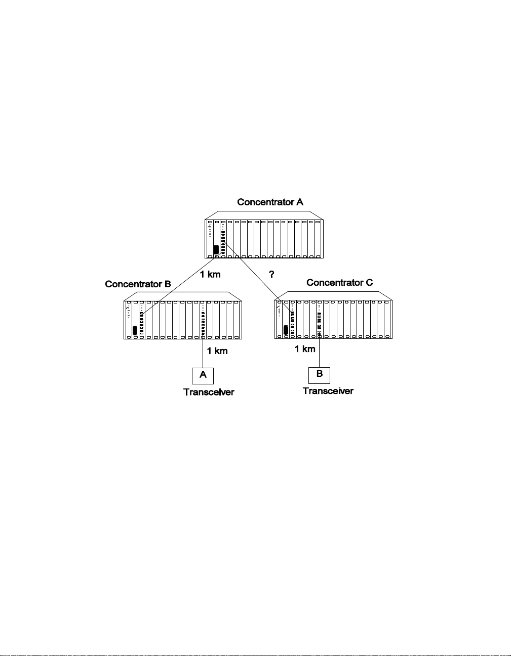
Example: Network With 3 Con ce ntrators
Figure 2-6 shows a network with 3 c oncentrators.
Figure 2-6. Network With 3 Concentrators
To determine the maximum allowable link distance between Concentrators
A and C:
1. Use 4200 m as the maximum netwo rk diameter for a pure fiber
network as defined by the 802.3 specification. (Rule 3).
2. Subtract the fiber equivalent of the three concentrators with
10BASE-FB Modules that occur on the path between the two
transceivers:
3 * 190 m eters = 570 meters (Rule 4)
Designing and Expanding the Network 2 - 19
Page 44

3. Subtract the known amount of fiber cable between the two
transceivers:
1 km + 1 km + 1 km = 3 km (Rule 5)
4. The remainder is the maximum allowable distance of the link
between Concentrato rs A and C:
4200 m - 570 m - 3000 m = 630 meters
5. Verify that the optical power budget is able to drive all the link
distances in the example. Because all link distances are only 1 km or
less, this is not a problem.
Example: Network with 8 Concentrators
Figure 2-7 sho ws a network with eight c onnected concentrators. Use this
example to determine if the distances between transceivers are all within
the 4200 meter maximum network d iameter restri ction for Ethernet
networks.
100m
500m 1km
Conc A Conc E Conc C
Transceivers
500m
Transceivers
100m
Note: All transceiver connections to concentrators are 100 meters
500m
Conc EConc D Conc F Conc G
Conc H
500m 400m
1km
100m
100m
Transceivers
Figure 2-7. Network Configu red With 8 Co ncentrators
2 - 20 ONline Ethernet 10 BA SE-FB Module Ins tallation an d Operat ion Guide
Page 45

In this example, the path between transceivers attached to Concentrators A
and G has the greatest fiber equivalent distance (4240 meters), e ven
though the link distance is less than the A to H path (3100 meters versus
3200 meters). Because 4240 meters e xceeds the 420 0 meter maximum,
this configuration is illegal and results in improper network operation.
Because it is not always obvious which path between transceivers has the
highest fiber equivalent distance, use Table 2-8 to help you determine the
equivalent distances.
Table 2-8. Fiber Equivalent Distances Bet w een Trans ceivers
Total Fiber
Link
Path
A - D 2700 5 950 3650
A - H 3200 5 950 4150
A - G 3100 6 1140 4240
D - H 1700 3 570 2270
D - G 1600 4 760 2360
G - H 2100 4 760 2860
Distance
Between
Transceivers
(meters)
Number of
Concentrators
Betwe en
Transceivers
Equivalent
Fiber Distance
of
Concentrators
(meters)
Total
Fiber
Equivalent
Distance
(meters)
Designing and Expanding the Network 2 - 21
Page 46

Fiber Backbone, Unshielded Twisted Pair to-the-Desk
Configuring a network with unshielded tw isted pair cabling to-the-des k is
similar to an all-fiber network because the cabling is star-wired in both
cases.
Be aware of the following additional rules for configuring a network:
❑ The four-repeater rule in Ethernet limits the number of 10BASE-T
modules between any two transceivers. The path from the TP port to
the backplane counts as 1/2 of a repeater and the path from the
backplane to the TP port counts as 1/2 of a repeater. You must add
a bridge if the path from one transceiver to another exceeds the
four-repeater rule.
❑ The equivalent fiber distance for the 10BASE-T Modules is defined in
“Understanding Network Configuration” in this chapter:
– 420 meters for s ignals that externally enter a 10BASE-T
Module port
– 165 meters for signals that internally ente r a 10BASE-T
Module through the ONline concentrator backplane
For each pair of 10BASE-T Modules that a signal goes through, there is a
fiber equivalent distance of 585 meters (420 m + 165 m =585 m). In
addition, if a signal makes a roundtrip through a 10BASE-T Module, (that is,
enters a 10BASE-T port exte rnally and exits through anot her port on the
same 10BASE-T Module) that counts as 585 meters of fiber equivalent
distance, and as a full repeater.
Example: Sample Configuration Distance Calculation
Use the following example to determine if the 10BASE-T Transceivers in
Figure are within legal Ethernet limits. Identify the two transceivers that
are likely to be the greatest fib er equivalent apa rt in Figure 2-8. In this
case, they are 10BASE-T Transceivers A and B.
2 - 22 ONline Ethernet 10 BA SE-FB Module Ins tallation an d Operat ion Guide
Page 47

Figure 2-8. Sample Configuration Distance Calculation
To determine if your network configuration is legal:
1. Use 4200 m as the maximum netwo rk diameter for a pure fiber
network as defined by the 802.3 specification.
2. Calculate the equivalent distances for each concentrator, and
subtract the total from 4200 (see figures for details).
3. Subtract all cable lengths between the two transceivers and if the
result is greater than zero, the configuration is within legal Ethernet
limits (Rule 5).
For the con figuration shown in Figure 2-8 to work, ensure the fiber
equiva lent distance between Transceiver A and Transceiver B is less than
4200 meters. As shown in the calculation, there are still 1510 meters left for
expansion in this configuration. Therefore, this configuration is legal.
Designing and Expanding the Network 2 - 23
Page 48

Fiber Backbone, Coaxial Connection
When connecting Thick or Thin Ethernet segments to an ONline network,
use an:
❑ ONline Ethe rnet Bridge Module
❑ ONline Ethernet Repeater Module
❑ External bridge or repeater
If you use a rep eater or the ONline Ethernet Repeater Mo dule, remember
that these products have an equivalent fiber distanc e of 800 meters.
Example: Connecting a Thin Ethernet (10BASE2) Segment
Figure 2-9 sho ws an exam ple of a Thin Ethernet segme nt connected to an
ONline System Concentrator using an IEEE Repeater
.
Figure 2-9. Thin Ethernet Segment Connected to an ONline
10BASE-FB Module
2 - 24 ONline Ethernet 10 BA SE-FB Module Ins tallation an d Operat ion Guide
Page 49

To determine if the configuration meets Ethernet distance limitati ons for
Transceivers A and B:
1. Use 4200 m as the maximum netwo rk diameter for a pure fiber
network as defined by the 802.3 specification (Rule 3).
2. Subtract the fiber equivalent distance of 420 m for the signal entering
the 10BASE-T Module from Transceiver B and 50 meters for the signal
exiting the 10BASE-FB Module within the same concentrator (Rule 4).
3. Subtract the fiber equivalent distance of 190 m for the signal
entering the 10BASE-FB Module in the top concentrator, and exiting a
different port on the same 10BASE-FB Module.
4. Subtract the fiber equivalent distance (800 m) of the IEEE Repeater
(Rule 4).
Note: In the reverse direction , a signal originating at Tr anscei ver
A loses 16 5 m of fib er equ i val ent dis t ance wh en it ex its t he
10BASE- T Module to which Transceiver B is connected and
140 meters for the signal entering the 10BASE-FB Module in
the lower concentrator. Because the overall fi ber
equivalence o f the path is greater for signals going from
Transceiver B to A, the fiber equivalence of this path
determine s whether the link meets the 42 00 m Ethernet
link maximum.
5. Subtract the sum of intervening cable lengths:
150 m + 50 m + 200 m + 2000 m + 100 m = 2500 m
6. The remainder is 4200 m - 420 m - 50 m - 190 m - 800 m - 2500 m =
240 m.
Designing and Expanding the Network 2 - 25
Page 50

Fault-Tolerant Configurations
This section contains descrip tions of the redundancy features built into the
ONline 10BASE-FB Modules. You can implement link redundancy between
concentrators using the port redundancy switch settings on the 10BASE-FB
Modules or through ONline network management.
This section contains the following topics:
❑ Configuring Ports for Fault Tolerance
❑ Implementing Total Backbone Fault Tolerance
Configuring Ports for Fault Tolerance
You can co nfigure the 10BASE-FB Module ports in one of four different
ways:
❑ Normal Configuration – Ports 1 through 4 operate as independent
cable ports.
❑ Standard Redundant Configuration – In this confi guration:
– Port 1 acts as the primary port and port 2 as the ba ck up
for 1
– Port 3 acts as the primary port and port 4 as the ba ck up
for 3
❑ Flexible Redun dant Configuration – You can arbitrarily assign
primary and backup ports to any pair of ports. You can configure
this mode only through the advanced management commands
provided with EMM V3.0 or greater.
❑ Normal and Redundant Co nfiguration – You can enable
redund ancy between one set of ports and have the remaining two
ports operate as independent ports.
2 - 26 ONline Ethernet 10 BA SE-FB Module Ins tallation an d Operat ion Guide
Page 51

Setting Redundancy
When you enable redundancy betw een two ports, the ports are
automatically enabled.
❑ Port 1 (or 3) as the primary link, which passes data.
❑ Port 2 (or 4) as the redundant link, which does not pass data in either
direction. However, the link is monitored for any failures (the Port
Status LED indicates any problems).
For maximum cable plant fault tolerance, connect both the primary and
backup ports back to the central concentrator (Figure 2-10). This
configuration allows the backup port to automatically take over if the
primary link fails
Designing and Expanding the Network 2 - 27
Page 52

.
Figure 2-10. Redunda nt Fiber Back bone Conf igurat ion
Note: Always enable redundancy in the lower level conc entrators
(those connecting to the central concentrators in the
star-wired topology).
In any redundant link pa th, only one end can be designated (that is,
activated) as a redundant port pair (ports 1 and 2 or ports 3 and 4). If you
enable 10BASE-FB Module ports at both ends as redundant, improper
operation of the redundant switchover mechanism occurs (see Figure 2-11).
2 - 28 ONline Ethernet 10 BA SE-FB Module Ins tallation an d Operat ion Guide
Page 53

If the primary l ink experiences a local or remote fault (except Low Light):
❑ The backup link activates within 10 milliseconds
❑ The primary ports disconnect (that is, they do not pass data to and
from the concentrator)
However, primary port diagnostics continue to operate. When the fault
clears, the primary port is enabled automatically. Once a switchover occurs,
the redundancy status indicators blink.
Each redun dancy status LED (located beneath the Activity LEDs):
❑ Is off - If you disable redundancy
❑ Is on - If you enable redundancy and both ports a re operational
❑ Blinks - If a switchover occurs due to a link failure
Implementing Total Backbone Fault Tolerance
You can add a backup ONline System Concentrator to provide total
backbone tolerance and link redundancy for your backbone network. As
shown in Figure 2-11, if the primary concentrator or any primary links fail,
the backup concentrator takes over. In this configuration:
❑ One port on the 10BASE-FB Module connects to the pri mary
concentrator
❑ The other port connects to the backup concentrator
You must also have a direct connection between the two concentrators.
Designing and Expanding the Network 2 - 29
Page 54

.
Figure 2-11. Total Backbo ne Fault-T o le rant Config ura tion
Example: Fiber Network with 3 Concentrators and a Fourth
Concentra to r in Full Redundan cy Con figuration
In Figure 2-12, three concentrators are active where Concentrator B is a
redundant concentrator for Concentrator A.
2 - 30 ONline Ethernet 10 BA SE-FB Module Ins tallation an d Operat ion Guide
Page 55

.
Figure 2-12. Fiber Network With 3 Concentrators
In Figure 2-12, the fiber equiva lent distance between transceivers a ttached
to Concentrators C and D is:
3 * 190 m + 1000 m + 1000 m + 500 m + 1000 m = 4070 m
Because this is less than 4200 me ters, the configuration is legal.
In Figure 2-12, if the main link from Concentrator A to Concentrator C
faults, the signal path (enabled through redundancy) includes Concentrator
B. By adding Concentrator B, the fiber equivalent distance has become too
great and the n etwork cannot w ork because the path between
Concentrators C and D is C-B-A-D:
4 * 190 + 1000 m + 2000 m + 500 m + 500 m + 1000 m = 5760 m
Because the sum is greater than 4200 meters, this configuration is not
legal. When designing a redundant network, be sure to consider the
backup route distance.
Designing and Expanding the Network 2 - 31
Page 56

Page 57

3
This chapter describes the installation procedures for the:
For your convenience, a quick reference installation chart is included. This
chapter includes the following sec tions:
Installing and Operating the Module
❑ ONline Ethernet Port-Switching 10BA SE-FB Module
❑ ONline Ethernet 10BASE-FB Module
❑ Precauti onary Procedures
❑ Unpackin g Procedures
❑ Quick Installation
❑ Setting the Dip Switc hes
❑ Installing the Module
❑ Configuring the Module
❑ Showing Mo dule Configurat io n
❑ Monitoring the Front Pa nel
❑ Verifying the LEDs and Ne twork Assignments
Installing and Operating the Module 3 - 1
Page 58

Note: Read the prec autionary procedures b efore unpacking the
module.
Precautionary Procedures
Electrostatic discharge (ESD) can damage static-sensitive devices on circuit
boards. Fol lo w these precautions when you handle the 10BASE-FB
Modules:
❑ Do not remove the board from its anti-static shielding bag until you
are ready to inspect it.
❑ Handle the board by the faceplate.
❑ Use proper grounding techniques when you install a 10BASE-FB
Module. These techniques include:
– Using a foot strap and grounded mat or wearing a
grounded static discharge wrist strap.
– Touching the grounded rack or other source of ground
just before you handle a 10BASE-FB Module.
3 - 2 ONline Ethernet 10BASE-FB Module Installation and Operation Guide
Page 59

Unpacking Procedu res
When unpacking your 10BASE-FB Module:
1. Verify that the 10BA SE-FB Modul e is the corre ct model by matching
the model number listed on the side of the shipping carton to the
model number you ordered (Model Numbers 5102M-FBP, 5104M-FBP,
or 5104M-FB 1).
Note that the p roduct model number printed on the shipping box
differs from the model number on the product. The mo del number
on the shipping box contains the prefix ’3C9’.
2. Remov e the module from the shipping carto n.
3. Remove the module from the anti-static shielding bag and inspect it
for damage. If the module appears to be damaged, replace it in the
anti-static shielding bag, return it to the shipping carton, and contact
your local supplier.
4. Keep the shipping carton and anti-static shielding bag in which your
module was shipped for repackaging the module for storage or
shipment.
5. Record the serial number of your 10BASE-FB Module. A log for this
and other information specific to your modules is included in the
ONline SystemConcentrator Installation and Operation Guide,
Appendix B, Slot Usage Chart.
Installing and Operating the Module 3 - 3
Page 60

Quick Inst allation
Table 3-1 outli nes the steps for installing your 10BASE-FB Module.
Table 3-1. Quick Installation Procedures
Step Procedure Section Title
1 Verify that your network complies with
the basic rules for network design.
2 Unpack the module. Unpacking
3 If you do not ha ve a mana gement m odul e
installed in the concentrator, configure the
dip switch settings to your specifications.
4 Insert the module into a blank slot in the
concentrator and tighten the faceplate
screws.
5 Establish connections from the 10BASE-FB
Module to another 10BASE-FB Module or
10BASE-FB Transceiver using the
appropriate connectors and cabling.
6 If you have a management module
installed in the concentrator, configure the
module using the management
commands.
Chapter 2,
Designing and
Expanding the
Network
Procedures
Setting the Dip
Switches
Installing the
Module
Installing the
Module
Configuring the
Module
7 Verify LED status for normal operation.
Note: To correct problems, consult the
troubleshooting techniques in Chapter 4.
3 - 4 ONline Ethernet 10BASE-FB Module Installation and Operation Guide
Verifying LED and
Network
Assignments
Page 61

Setting the Dip Sw itc h es
The 10BA SE-FB Modules have two 10-position dip switches (S1 and S2)
located on the board. Figure 3-1 shows the dip switches on the 10BASE-FB
Modules and the factory settings.
❑ Dip switch S1 on the Port-Switching Module differs from dip switch
S1 on the Module-Switching Module. Figure 3-1 contains examples
of both dip switches.
❑ Dip switch S2 is identical for both the Port-Switching Module and
Module-Switching Module except the Module-Switching Module does
not provide High power optics.
You ma y need to reconfigure one or more of these switches depending on
your co nf i gu r at i on requireme nt s .
The dip switch settings for the 10BASE-FB Modules are ignored if an ONline
management module is installed in the concentrator. For this reason, use
the management commands (rather than the dip switches) to configure
the 10BASE-FB Modules. If you have an insta ll ed management module,
install the 10BASE-FB Module first and then refer to the Configuring the
Module section in this chapter for more information.
This section describes:
❑ Setting Dip Switch S1
❑ Setting Dip Switch S2
Installing and Operating the Module 3 - 5
Page 62
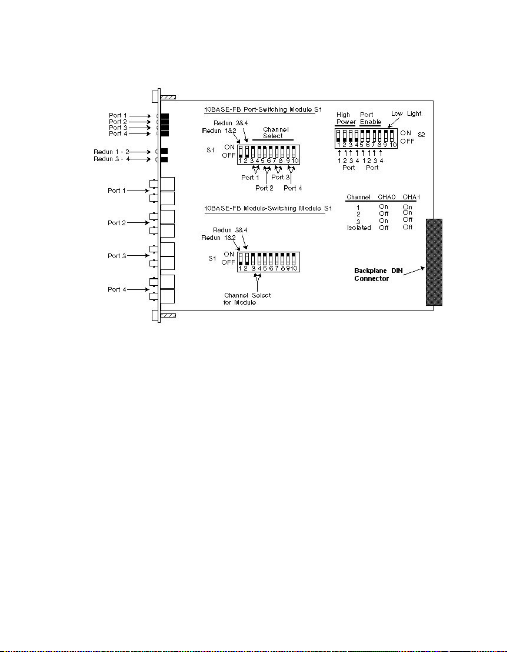
Figure 3-1. 10BA SE-FB Module Dip Switch Locations
Note: The Port-Switching 10BASE-FB Module is also available as a
two-port module (Model Number 5102M-FBP) for
installations that do not require four fiber ports. When
using the switches for the two-port module, all switches
operate identical to the switches on the four-port module
with the exception of port 3 and port 4 switches. These
switches do not perform any operation.
3 - 6 ONline Ethernet 10BASE-FB Module Installation and Operation Guide
Page 63

Setting Dip Switch S1
The S1 dip switch on the 10BASE-FB Modules have 10 switches. These
switches allow you to enable or disable redun dancy between ports 1 & 2
and 3 & 4.
The S1 dip switch on the:
❑ Port-Switching 10BASE-FB Module allows you to - assign each port to
a backplane channel
❑ Module-Switching 10BASE-FB Module allows you to - assign the
module to a backplane channel
For a definition of each dip switch function, refer to the Configuring the
Module section.
Table 3-2 lists the functions and settings for switches 1 an d 2.
Table 3-2. Dip Switch S1 Settings for Switches 1 and 2
Switch Label Function
1 REDN12 Enable/disable
redundancy
between ports 1
and 2
2 REDN34 Enable/disable
redundancy
between ports 3
and 4
Installing and Operating the Module 3 - 7
Factory
Default
disable disable enable
disable disable enable
Switch Setting
Off On
Page 64

Table 3-3 lists the functions and settings for switches 3 through 10.
Table 3-3. Dip Switch S1 Settings for Switches 3 to 10
CHA0 CHA1 Channel Selection
Switch Setting O n On 1 (factory default )
Off On 2
On Off 3
Off Off Isolated
Port-Switching Modul e : Port
operates independent of any
backplane channel.
Module-Switching Module:
Module operates independent of
any backplane channel.
3 - 8 ONline Ethernet 10BASE-FB Module Installation and Operation Guide
Page 65

Setting Dip Switch S2
Dip switch S2 on the 10BASE-FB Modules have 10 switches. These switches
allow you to:
❑ Enable high or normal optical power for each port
❑ Enable or disable any of the fou r ports
❑ Enable or disable low light detection for the module
Table 3-4 lists the functions and settings for dip switch S2. Switch 10 is not
used.
Table 3-4. Dip Switch S2 Settings
Switch Label Function
1 P1 HIPWR Po rt 1 High or
Normal power
2 P2 HIPWR Po rt 2 High or
Normal power
3 P3 HIPWR Po rt 3 High or
Normal power
4 P4 HIPWR Po rt 4 High or
Normal power
5 P1 EN Enable/disable
Port 1
6 P2 EN Enable/disable
Port 2
7 P3 EN Enable/disable
Port 3
8 P4 EN Enable/disable
Port 4
Factory
Default
disable
(normal)
disable
(normal)
disable
(normal)
disable
(normal)
enable disable enabl e
enable disable enabl e
enable disable enabl e
enable disable enabl e
Switch Setting
Off On
disable enable
disable enable
disable enable
disable enable
Installing and Operating the Module 3 - 9
Page 66

Table 3-4. Dip Switch S2 Settings (Continued)
Switch Label Function
9 LOL EN Enable/disable
10 Not Used
Installing the Module
You do not need to power down the ONline System Concentrator to install
the 10BASE-FB Modules. You can insert or remove the module while the
concentrator is operating (this is called a hot swap).
To install a 10BASE-FB Module:
1. Do one of the following:
❑ If you do not have a management module installed in the
concentrator, set the dip switches on the board (if different from
the default setting) . After you c omplete the installation
procedure, go to the Monitoring the Front Panel section to verify
the installation.
module Low
Light Detection
Factory
Default
enable disable enable
Switch Setting
Off On
❑ If you have a management module installed in the concentrator,
complete thi s installation procedure and then configure the
module using the commands as described in the Configuring the
Module section.
2. Locate a blank slot in the concentrator. If there is no blank slot,
remove a blank panel on the concentrator to expose a slot for a
10BASE-FB Module.
3 - 10 ONline Ethernet 10 BA SE-FB Module Ins tallation an d Operat ion Guide
Page 67

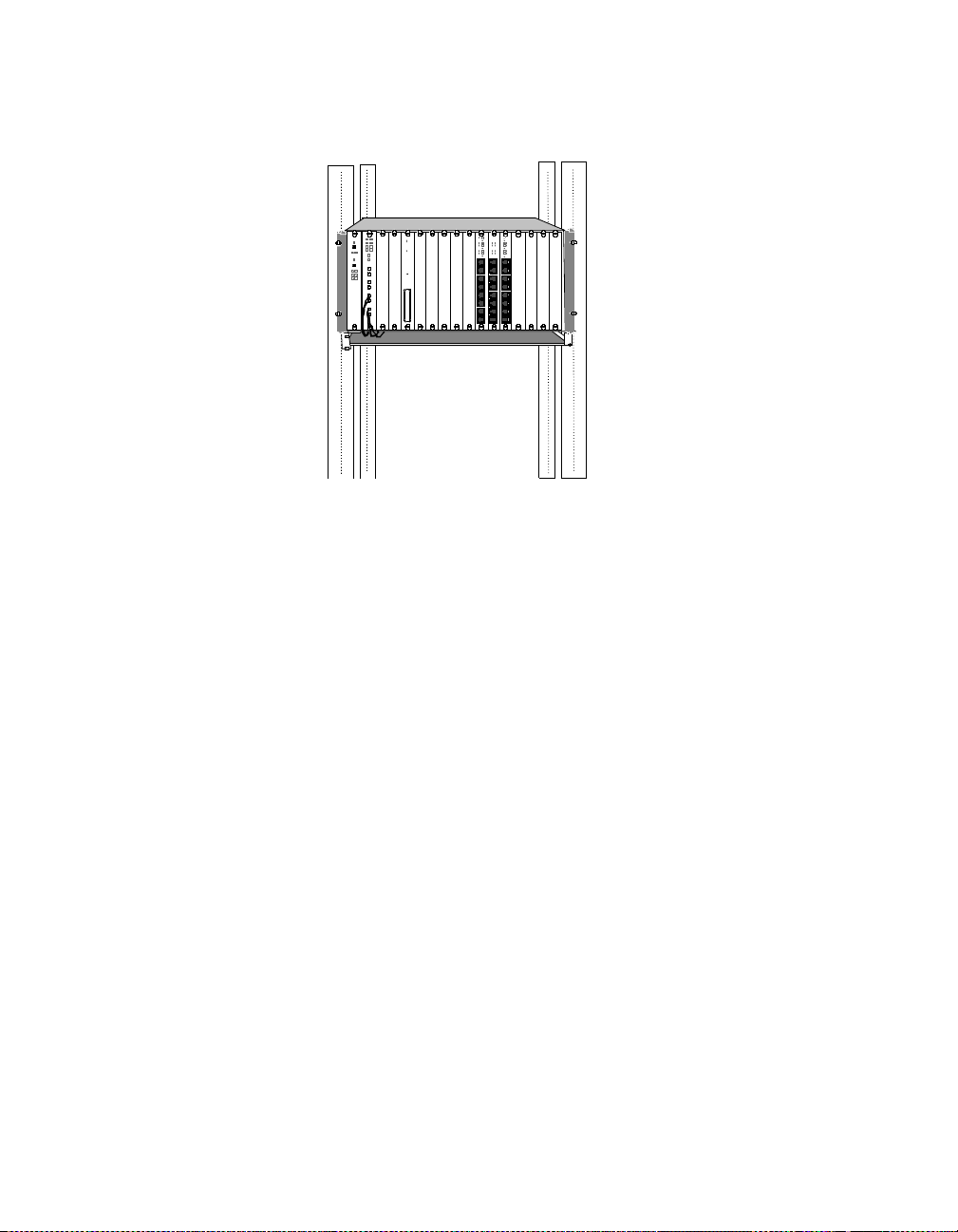
3. Insert the module into the board guides at the top and bottom of the
slot and slide it into the concentrator. Make sure that the connector
is well-seated into the backplane o f the concentrator.
Figure 3-2 shows the installation of a 10BASE-FB Module
.
Figure 3-2. Installing the 10BASE-FB Module
4. Fasten the spring-loaded screws on the front of the 10BASE-FB
Module faceplate to the concentrator using your fingers (do not
overtighten).
5. Remove the plastic fiber optic covers from the cable ports. Keep
unused cable ports capped to keep the optics clean.
6. Attach the fiber cables to the fiber ports on the front of the
10BASE-FB Module as shown in Figure 3-3.
Inst alling and Operating the Module 3 - 11
Page 68
.
Figure 3-3. 10BASE-FB Module Connection
7. Make sure transmit and receive cables are:
❑ Clearly marked or color-co ded.
❑ Connected to the appro priate ports on the 10BAS E-FB Module.
❑ Properly cleaned with an appropriate fiber optic cleaning solution
before installation.
Note: Do not exceed the bend radius for the fiber cable when
directing the cables under the concentrator. Refer to the
cable manufacturer's specifications for minimum bend
radius.
8. Attach the other ends of the cables to either:
❑ Another 10BASE-FB module
❑ 3Com 10B ASE-FB Star Coupler port
❑ 3Com 10BASE-FB Tran sc eiver
3 - 12 ONline Ethernet 10 BA SE-FB Module Ins tallation an d Operat ion Guide
Page 69

❑ 3Com Faul t-Tolerant 10BASE-FB Transceiver
Make sure that the transmit fiber at one end always connects to a
receive port at the other end.
Caution: Do not connect this module to an ONline 10BASE-FL
Module or to any other product that is no t compatible
with the 10BASE-FB modules. These illegal connections
may cause network failure.
Configuring the Module
The ONline management modules can configure the following settings on
the 10BASE-FB Modules:
❑ Enable and disable each port on the module
❑ Set the ports to independent Ethernet networks within the
concentrator (Port-Switching 10BASE-FB Module)
❑ Set the module to independent Ethernet networks within the
concentrator (10BASE-FB Module)
❑ Set redundancy between two ports on the module or between ports
on another 10BASE-FB Module (using Advanced EMM V4.01 or
higher)
❑ Enable an d disable the low light warning
❑ Set the fiber optic transmission power for each port
The following ONline management modules provide network management
capabilities for the ONline System Concentrator and its modules:
❑ Ethernet Management Module V4.01
❑ Token Ring Management Module V3.10
❑ FDDI Man ag ement Module V2.00
Inst alling and Operating the Module 3 - 13
Page 70

When an ONline management module is installed in a concentrator, all of
the dip switch settings on the 10BASE-FL Module are overridden.
When you first install the module:
1. The network (channel) defaults to i solated mod e. The ports are
automatically disabled so that unapproved users cannot be added.
Therefore, you must enable the ports you wish to use and set the
ports to the appropriate Ethernet network through the management
commands.
2. All other module settings retain the same default values as the dip
switch default values. Therefore, you only need to changes these
values through management if you do not want th e default values.
This section describes the management commands to set these features.
For additional information on the available network management features,
refer to:
❑ The appropriate ONline management module installation and
operation guide
❑ ONline Management Commands Guide
Enabling Ports
You can enable or disable each of the four ports on the mo dule. When a
port is enabled, it can trans mit data onto and receive data from the
network to which the module is assigned. Disable all unused ports on the
10BASE-FB Modules to prevent the Status indicators from flashing a No
Light condition.
To enable or disable a specific port, use the following manag ement
command:
SET PORT {
3 - 14 ONline Ethernet 10 BA SE-FB Module Ins tallation an d Operat ion Guide
slot.port
{
slot
} MODE {enable}
.all} {disable}
Page 71

Selecting a Network
Both models of the Po rt-Switching Module (Model Numbers 5102M-FBP or
5104M-FBP) support Port-Switching technology. This feature enables you to
assign each port on the module to any of three Ethernet networks (or
isolated) on the ONline System Concentrator backplane.
To set a port to a network or to isolated mode, use the following
management command:
SET PORT {
{
The 10BASE-FB Module (Model N umber 5104M-FB) enables you to assign
the module to any of the three Ethernet networks (or isolated) on the
ONline System Concentrator backplane.
To set a module to a network or to isolated mode, use the following
management command:
SET MODULE {
slot.port
slot
slot
} NETWORK {ethernet_1}
.all} {ethernet_2}
{ethernet_3}
{isolated}
} NETWORK {ethernet_1}
{ethernet_2}
{ethernet_3}
{isolated}
Note: The dip switch settings on the module refer to the
backplane connection as the “channel” connection. The
channel se tting and the network setting are the sam e.
Modules or ports set to the same netwo rk communicate
with each other.
Inst alling and Operating the Module 3 - 15
Page 72

Enabling Port Redundancy
You can enable port redundancy in one of the following ways:
❑ If you have network management, you can enable or disable main
port redundancy between any two ports on the 10BASE-FB Module.
❑ If you do not have management, you can use the dip switches on the
module to configure redundancy between ports 1 and 2 on the
module o r ports 3 and 4.
For example, when you enable redundancy:
1. Port 1 becomes the primary link and po rt 2 is the redundant link.
2. If the primary link (port 1) fails, the redundant link (port 2) is engaged
automatically, thus preventing a network failure.
3. When you disable redundancy, each port works independently.
Note: Enabling port redundancy for two ports autom atically
enables the ports, even if the ports were previously
disabled.
The redundancy status LEDs, located between the sets of port LEDs and the
port connectors on the 10BASE-FB Module, are:
❑ Off - When you disable redundancy (default setting)
❑ On - When you enable redundancy
To set redundancy between ports, use the following management
command:
SET PORT {
slot.port
} MODE REDUND ANT {
slot.port
}
To turn off redundancy between ports, use the MODE NON_REDUNDANT
option. Redundancy configurations are shown in Chapter 2, Designing and
Expanding the Network.
3 - 16 ONline Ethernet 10 BA SE-FB Module Ins tallation an d Operat ion Guide
Page 73

When you set redundancy between two ports on the same 10BASE-FB
Module and the primary port and the redundant port experience a link
failure simultane ously, and you disable redundancy:
❑ The prim ary port is disabled
❑ The redundant port is enabled
Enabling Low Light Warning
You can enable or disable low light warning for all ports on the module.
When you enable low light warning, the Status LED of the port which
detects the low light condition blinks 6 times. (A low light condition is
defined as power received between -26.0 dBm and -30.0 dBm peak power.)
You may have a legal configuration in which low light is acceptable to span
a long distance. In this case, you may want to disable the low light
warning so the Status LED does not blink for this connection.
To enable or disable low light warning for a port, use the following
management command:
SET PORT {
slot.port
{
slot
} LOW_LIGHT_WARNING {enable}
.all} {disable}
Enabling Optical Power
High-power optics are standard in all 3Com ON line fiber optic produ cts.
The higher power allows you to directly conne ct buildings as far as 4.0
kilometers apart without the additional expense of signal-boosting
equipment. However, it is necessary to set a p ort to the norma l power
setting when it is connected to a 3Com 10BASE-FB fiber optic product.
Each port on the Port-Switching 10BASE-FB module can be set to high or
normal powe r through the dip switches or through management
commands. To set a port to hi gh or normal po wer, use the fol lo wing
management command:
SET PORT {
slot.port
{
slot
} HIGH_POWER {enable}
.all} {disable}
Inst alling and Operating the Module 3 - 17
Page 74

The 10BASE-FB Module-Switching Module can be set to high or normal
power through the dip switches (see Table 3-4).
Saving Module Configuration
To save the module and port settings to management module memory, use
the following command:
SAVE M OD ULE _P ORT
Showing Modu le Config urat ion
You can display status information about the 10BASE-FB Modules using the
following commands:
❑ SHOW MODULE
❑ SHOW MODULE VERBOSE
❑ SHOW PORT
❑ SHOW PORT VERB OSE
For example, the following command displays detailed information about
port 1 on the Port-Switching 10BASE-FB Module in slot 8 of the
concentrator.
ONline> show port 8.1 verbose [ENTER]
Port Display for Module 5104M-FBP:
Port Mode Status Network General Information
_____________________________________________________________
08.01 ENABLED OKAY ETHERNET_2
Network Dip Setting: ETHERNET_2
Mode Dip Setting: ENABLED
Low Light Warnin g: ENABLED
Low Light Warning Dip Setting: ENABLED
High Power Optics: ENABLED
High Power Optics Dip Setting: DISABLED
3 - 18 ONline Ethernet 10 BA SE-FB Module Ins tallation an d Operat ion Guide
Page 75

This display tells you the status of the specific port. It includes the
management and dip switch settings from the board.
The following command displays detailed information about the 10BASE-FB
Module in slot 8 of the concentrator.
ONline> show module 8 verbose [ENTER]
Port Display for Module 5104M-FB1:
Slot Module Version Network General Information
08 5104M-FB1 00x ISOLATED ETHERNET_2
5104M-FB1: ONline Ethernet 10BASE-FB Module
Network Dip Setting: ETHERNET_1
Low Light Warning: DISABLED
Low Light Warning Dip Setting: DISABLED
This display tells you the status of the specific module. It includes the
management and dip switch settings from the board.
For more information on the SHOW commands, refer to the:
❑ Appropriate ONline management module installation and operation
guide
❑ ONline Management Commands Guide
Monitoring the Front Panel
The LEDs on the front panel of the 10BASE-FB Module allow you to monitor
the status of each port. The 10BASE-FB Module has 10 LEDs on the front
panel that allow you to monitor diagnostic, activity, and redundancy status
for each port. Figure 3-4 shows the locations of these indicators.
Inst alling and Operating the Module 3 - 19
Page 76

Figure 3-4. 10BASE-FB Port-Switching Module Faceplate and
ONline System Concentrator
3 - 20 ONline Ethernet 10 BA SE-FB Module Ins tallation an d Operat ion Guide
Page 77

Table 3-5 describes how to inte rpret the 10BASE-FB Module LEDs.
Table 3-5. Interpreting the 10BASE-FB Module LEDs
LED Name Color State Ind icates
Activity
(Ports 1-4)
Status
(Ports 1-4)
yellow O ff No packets are received on the
fiber segment.
On Constant activity on the fib er
segment.
Blinking Module receives packets from
segment to which it is attached.
green Off Port disabled.
On Port enabled or in standby and link
integrity is OK.
1 blink No light detected.
2 blinks Jabber .
3 blinks Partition.
4 blinks Remote f ault.
5 blinks Invalid data received.
6 blinks Low light r ec ei ved (you can d isa ble
it using Low Light switch setting).
Redundancy
(Ports 1-2)
(Ports 3-4)
green Off Redundancy is disabled; ports are
independe nt of each other.
On Redundancy is enabled between
ports 1 & 2 and 3 & 4.
Blinki ng Switchover has tak en place or there
has been a link failure.
Inst alling and Operating the Module 3 - 21
Page 78

Verifying L ED and Netw ork As signme nt s
Once you install the module, verify its operation through the front panel of
the ONline Controller Module. The Controller Module is equipped with an
LED check button on the front panel. Use the LED check buttonto:
❑ Verify LED operation
❑ Verify network (channel) assignment
When you press this button, the Controller Module initiates a test to all
modules in the concentrator. All LEDs should respond by lighting
continuously for approximately five seconds. Any LED that does not light is
defective.
After the 5 secon ds elapse, the diagnostic continues with a netw ork
(channel) check of all modules. Each Status LED should respond by blinking
the number of times to correspond with the network to which the module
is assigned. The network check sequence repeats 5 times. Table 3-6
explains the network c heck codes.
Table 3-6. Network Check Codes
LED State Network Configuration
1 Blink Module or port is configured for network 1
2 Blinks Module or port is configured for network 2
3 Blinks Module orport is configured for network 3
Off Module or port is isolated (operates independent of any
network)
Page 79

4
This chapter describes fault conditions and troubleshooting procedures for
the ONline Ethernet 10BASE-FB Modules.
This chapter contains the following sections:
Troubleshooting
❑ Troubleshooting Using the Port Activity LEDs
❑ Troubleshooting Using the Port Status LEDs
❑ Technical As sistance
Troubleshooting 4 - 1
Page 80

Troubleshoo ting Using the Po rt Ac ti vit y LEDs
If a port Activity LED does not light, use Table 4-1 to help troubleshoot the
problem.
Table 4-1. Troubleshooting Using the Port Activity LED s
LED
State
Off There is no traffic received
Possible Cause Corrective Action
from the segm ent.
Port is disabled. Use the EMM to check if the
Power is off. Check the Controller Module
Activity LED has burned
out.
10BASE-FB Module port is
faulty.
10BASE-FB Module is
faulty.
Backplane connection is
bad.
None.
port i s enable d or che ck the port
dip switch setting.
Power LEDs.
Press the LED check button on
the Controller Module.
Connect the cable to a different
port.
Try a different 10 BASE-FB
Module.
Reinsert the 10BAS E-FB
Module. If this fails, try another
concentrator slot.
4 - 2 ONline Ethernet 10BASE-FB Module Installation and Operation Guide
Page 81

Troubleshoo ting Using the Port Stat us LEDs
A blinking Port Status indicator is always a sign that the port detects a
potential problem. Once a port detects a problem, you can further analyze
the problem by counting the number of blinks. Table 4-2 provides
troubleshooti ng suggestions for each of the blinkin g s equences.
Table 4-2. Troubleshooting Using the Port Status LEDs
LED State Indication Possible Caus e Corrective Action
Off Port Disabled Port disabled. Enable port.
10BASE-FB
Module not
powered up.
Broken LED. Press the LED check
Bad 10BAS E-FB
Module.
Check concentrator
power status.
Reinsert th e
10BASE-FB Module.
button on Controller
Module.
Replace module.
Troubleshooting 4 - 3
Page 82

Table 4-2. Troubleshooting Using the Port Status LEDs (Continued)
LED State Indication Possible Caus e Corrective Action
1 Blink No Light
Received
Cables crossed. Verify TX on remote
device is connected to
RX on 10BASE-FB
Module.
Insufficient
optical power
received.
Broken fiber
cable.
Bad fiber
connections.
Check 10BASE-FB
Modul e op tical power
using a light meter.
Try High power on
remote device.
Check optical power of
remote device.
If optical power levels
are OK, check cable; it
may be bad or too
long.
Check and fix RX fiber
link.
Clean and reconnect
fiber (both ends ).
Bad remote
device or port.
Bad 10BAS E-FB
Module.
4 - 4 ONline Ethernet 10BASE-FB Module Installation and Operation Guide
Replace remote device
or try another port.
Replace module.
Page 83

Table 4-2. Troubleshooting Using the Port Status LEDs (Continued)
LED State Indication Possible Caus e Corrective Action
2 Blinks Jabber Loop in network. Disconnect each link
in the network one at
a time to isolate the
loop.
Bad 10BAS E-FB
Module.
3 Blinks Partition Looped fiber
cable.
4 Blinks Remote Fault Remote device
detects a
problem.
Bad remote
device.
Bad 10BAS E-FB
Module.
Replace module.
Remove looped cable.
Check remote device's
status LEDs to identify
problem.
Try another port or
replace device.
Replace the module.
Troubleshooting 4 - 5
Page 84

Table 4-2. Troubleshooting Using the Port Status LEDs (Continued)
LED State Indication Possible Caus e Corrective Action
5 Blinks Invalid Data Receive light
intensity too
high.
Connection
made to
10BASE-FL
Module.
Bad fiber
connections.
Broken or
cracked fiber.
Bad remote
device.
Bad 10BAS E-FB
Module.
6 Blinks Low Light
Received
Low light
received.
Verify that received
optical power level is
correct. Refer to
Chapter 2 (Link
Distances).
Unplug the
connection. 10BASE-FL
is not compatible with
this 10BASE-FB
Module.
Clean and reconnect
fiber (both ends ).
Check and fix RX fiber
link.
Try another port or
replace device.
Replace the module.
Verify optical power
received is at low end
of optical power
budge t by doing an
optical power
calculation. If value is
acceptable, disable low
light detectio n.
Legal
configuratio n
with acceptable
low light.
4 - 6 ONline Ethernet 10BASE-FB Module Installation and Operation Guide
Disable low light
detection or enable
High power at remo te
end.
Page 85

Technical As sist anc e
You can receive assistance for installing and troubleshooting the 10BASE-FB
Module by calling either your 3Com reseller or 3Com Technical Support. Be
prepared to supply a representative with the following information:
❑ Description of the problem
❑ Steps you have taken to try and correct the problem
❑ Type and software version of the ONline network management
module being used
❑ Version of software installed on your 10BASE-FB Module
❑ Status of the front panel LEDs
❑ Configuration of your concentrator
(you may find it helpful to refer to the Slot Usage Chart in Appendix B
of the ONline System Concentrator Installation and Operation Guide
for a record of this information)
Refer to Appen dix B for instructio ns on contacting Technical Su pport for
your product.
Troubleshooting 4 - 7
Page 86

Page 87

A
Specifications
This appendix lists specifications for the Port-Switching 10BASE-FB Module
and the 10BASE-FB Module. Specification differences b etween the
Port-Switching 10BASE-FB Module and the 10BASE-FB Module are indicated.
Specifications for the modules include:
❑ General Specifications
❑ Optical Specifications
❑ Power Specifications
❑ Environmental Specifications
❑ Mechanical Specifications
❑ Miscellaneous Specifica tions
❑ 3Com 10BASE-FB Netw ork Products
❑ 10BASE-FB Cables and Co nnectors Specifications
Specifications A - 1
Page 88

General Specifi cat ions
Table A-1 lists gene ral specifications for the 10B ASE-FB Module.
Table A-1. General Specifications
10BASE-FB Module Model Numbers 5102M-FBP
Collision Detection 100% d eterministic
Configuration Rules Complia nt with IEEE 802.3
Jabber Protec tion 10.8 ± 1 msec
Maximum Number of Nodes 1024
Backplane Interface 96-pin edge connector,
External Connector 4 pairs of fiber ports (ST, SMA, or
5104M-FBP
5104M-FB1
10BASE-FB specifications
compatible w ith the ONline
System Concentrator
FC connectors)
Host Interface ONline System Concentrator bus
interface standard
Installation Attachment Two thumbscrews on the
mounting bracket
A - 2 ONline Ethernet 10BASE-FB Module Installation and Operation Guide
Page 89

Optical Speci ficat ions
This section lists the optical specifications for the 10BASE-FB Module,
including:
❑ Transmitter Specifications
❑ Receiver Specifications
❑ Supported Fiber Optic Cables
❑ Fiber Optic Interface
Transmitter Specifications
Light Source: GaA1As LED at wavelength 820 ± 20 nm . Power coupl ed int o
fiber cable in clusive of ST, SMA , or FC connector loss.
TableA-2 lists normal and high power transmit specifications.
Table A-2. Transmit Power
Cable Type Normal Power High Power
100/140 micron,
0.29 NA fiber
85/125 micron,
0.29 NA fiber
62.5/125 micron,
0.275 NA fiber
50/125 micron,
0.20 NA fiber
- 11.5 dBm ( ± 3. 0 dBm) - 4.5 dBm (± 2.25 dBm)
- 14.0 dBm (± 3.0 dBm) - 7.0 dBm (± 2.25 dBm)
- 17.0 dBm (± 3.0 dBm) - 10.0 dBm (± 2.25 dBm)
- 21.5 dBm ( ± 3. 0 dBm) - 14.25 dBm (± 2.25 d Bm)
Specifications A - 3
Page 90

Receiver Specifications
Table A-3 lists recei ver specifications for t h e 10BASE-FB Module.
Table A-3. Receiver Specifications
Light Detector Silic on PIN ph otodiode
Input Range Optical power input of -8.0 dBm to -3 0.0 dBm
Bit Error Rate 1 in 10
Dynamic Range 22.0 dB
Supported Fiber Optic Cables
You can use the following fiber optic cables with the 10BASE-FB Module:
❑ 50/125
❑ 62.5/125
❑ 85/125
-10
over dynamic range
❑ 100/140
The fiber op tic cable must be:
❑ Micron diameter graded index
❑ Duplex fiber
❑ 150 MHz km ratin g or better
A - 4 ONline Ethernet 10BASE-FB Module Installation and Operation Guide
Page 91

Fiber Optic Interface
Table A-4 lists specifications for the fiber optic interface.
Table A-4. Fibe r Optic Interface S pecifications
Data Rate 10 Mbps (million bits per second)
Data Modulation Manchester
Diagnostic Modulation Pulse Width
Fiber Optic In terface ST-, SMA-, and FC-type
Signaling Compatible with all 10BASE-FB
Power Requirements
Table A-5 lists power requiremen ts for the 10BASE-FB Module.
Table A-5. Power Requirements
and 10BASE-FB products
Power Requirements 1.7 Amp @ 5 V
Fuse 4.0 Amps for 5 V, Fast blow
Power Consumption 8.5 W atts
BTU/hour 29.0
Specifications A - 5
Page 92

Environmental Spec ifi cat ions
Table A-6 lists electrical specifications for the 10BASE-FB Module.
Table A-6 . Electrical Spe cifications
Operating T emperature 0° to 50° C (32° to 122° F )
Storage Temperature -30° to 65° C (-22° to 149° F)
Humidity Less than 95%, non-condensing
Mechanical Specifications
Table A-7 lists mech anical specificatio ns for the 10BASE-FB Module.
Table A-7. Mechanical Specifications
Dimensions 1.0" W x 10.25" L x 8.5" H
(2.54 cm x 26.04 cm x 21.6 cm)
Weight 1.25 lb. (0.57 kg.)
3Com 10BASE-F B Ne twork Pro duc t s
This section describes the fiber Ethernet products available from 3Com. In
addition to the Ethernet 10BA SE-FB Modules describe d in this guide, the
following fiber products are available from 3Com:
❑ 3Com 10BASE- FB Transceiver - The 3Co m 10BASE-FB Tra ns ceiver
(Model Number 5101T-FB) connects a device to the fiber network.
The 10BASE-FB Transceiver has an AUI port and a fiber port. The AUI
port connects to the device thro ugh the transceiver ca ble. The fiber
port connects to the fiber network.
A - 6 ONline Ethernet 10BASE-FB Module Installation and Operation Guide
Page 93

❑ 3Com Fault-Tolerant 10BASE-FB Transceiver - The 3Com
Fault-To lerant 10BASE-FB Transceiver (Model Number 5102T-FBFT)
provides fault tolerance to-the-desktop. The transceiver connects an
existing network to a fault-tolerant fiber backbone network. It also
provides a fault-tolerant network connection for a mission-critical
device.
❑ 3Com 10BASE-FB Star Coupler - The 3Com 10BASE-FB Star Coupler
(Model Number 9308S-FB ) is a pure fiber hub that provides both
backbone and to-the-desk connectivity.
10BASE-FB Cable and Connector Spe ci ficati ons
This section contains information on 10BASE-FB cables, and connectors.
Use the information in the following sections to ensure that the cables and
connecting hardware m eet requirements.
You can use many types of fiber cables and connectors to link your
10BASE- FB Module to your network. These c ables and connectors are
explained in the secti ons that follow. For proper operation, use only
approved cables when you install all equipment.
10BASE-FB Cables
The fiber optic cable diameters that th e 10BASE-FB Module supports must
meet the following qualifications:
❑ 50/125, 62.5/125, 85/125, o r 100/140 µ m graded index fiber
❑ duplex fiber with a 150 MHzKm rating or better
Note that network link distances are affected by the grade of cable you
choose. The quality of fiber cable varies significantly. Typically, measure
quality in terms of the signal loss per km. The less amount of loss, the
better the cable quality. Good quality 62.5 µm fiber typical ly has a 3 to 4
dB loss per kilometer.
Specifications A - 7
Page 94

10BASE-FB Connectors
The 10BASE-FB Modules are available in both SMA-type, ST-type, and
FC-type fiber connecto rs for direct connection to a Fiber Ethernet LAN.
When you order a 10BASE-FB Module, use the part numbers listed in
Table A-8 for the correct connec tor type.
Table A-8. 10BASE-FB Module Part Numbers
Connector Type
Port-Switching
10BASE-FB Fiber
Module
10BASE-FB Fiber Module
ST-type 5104M-FBP-ST
5102M-FBP-ST
SMA-type 5104M-FBP-SMA
5102M-FBP-SMA
FC-type 5 104M-FBP-FC
5102M-FBP-FC
5104M-FB1-ST
5104M-FB1-SMA
5104M-FB1-FC
Connecting Fiber Cables
If you use a concentrator in your network setup, connect cables first at the
active concentrator location. Refer to the ONline System Concentrator
Installation and Operation Guide for more information about the
concentrator connections and configuration rules.
A - 8 ONline Ethernet 10BASE-FB Module Installation and Operation Guide
Page 95

B
Technical Support
3Com prov ides easy acce ss to technical support information through a
variety of services. This appendix describes the following services:
❑ On-line Technical Support
❑ Support from Your Network Supplier
❑ Support from 3Com
❑ Returning Products for Repair
❑ Accessing the 3Com MIB
❑ 3Com Technical Publications
On-line Technical Support
3Com offers worldwide pro duct support through the following on-line
systems:
❑ Email Technical Service
❑ World Wide Web Site
Technical Support B - 1
Page 96

Email Technical Support
You can contact the Integrated Systems Division (formerly Chipcom) on the
Internet for technical support using the e-m ail address
techsupp@chipcom.com.
World Wide Web Site
You can ac cess the latest networking information on the 3Com W orld
Wide Web site by entering our URL into your Internet browser:
http://www.3Com.com/
This service features news and information about 3Com products,
customer serv ic e and support, the 3Com latest news releases, selected
articles from 3TE CH™, the 3Com award-winning technical journ al, and
more.
You can contact the Integrated Systems Division on the World Wide Web
by entering our URL into your Internet b rowser:
http://www.chipcom.com/
There are li nks between both WWW pages to view information from all
3Com divisions.
Support from Your Network Supplier
If additional assistan ce is required, conta ct your network supplier. Many
suppliers are authorized 3Com service partners who are qualified to provide
a variety of services, including network planning, installation, hardware
maintenance, application training, and support services.
B - 2 ONline Ethernet 10BASE-FB Module Installation Guide
Page 97

When you contact your network supplier for assistance, have the following
information ready:
❑ Diagnostic error messages
❑ A list of system hardware and software, including revision levels
❑ Details about recent configuration changes, if applicable
If you are unable to con tact your network supplier, see the following
section on how to contact 3Com.
Support from 3Com
If you are unable to receive support from your network supplier, technical
support contracts are ava ilable from 3Com.
For direct access to customer service for Integrated Systems Division
products in:
❑ U.S.A. and Canada - call (800) 724-24 47
❑ Asia Pacific - call (508) 787-5151
❑ Europe - refer to the table below. For European countries not listed,
call 31 30 60 299 00.
Country Telephone Num ber Country T elephone Num ber
Belgium 0800 71429 Netherlands 06 0227788
Denmark 800 17309 Norway 800 11376
Finland 0800 113153 Spain 900 983125
France 05 9179 59 Sweden 020 795482
Germany 0130 82 1502 U.K. 0800 966197
Ireland 1 800 553117 U.S. 800 876-3266
Italy 1678 79489
Technical Support B - 3
Page 98

For access to customer service for all 3Com products, call (800) 876-3266.
You can also contact the Integrated Systems Division (ISD) on the Internet
by using the e-mail add ress techsupp@chipcom.com.
Returning Produc ts for R epair
A product sent directly to 3Com for repair must first be assigned a Return
Materials Authorization (RMA) number. A product sent to 3Com without
an RMA number will be returned to the sender unopened, at the sender’s
expense.
To obtain an RMA number for Integrated Systems Division products
(formerly Chipcom ), use the following numbers .
Country Telephone Number Fax Number
U.S. and Canad a (800) 724-2447 (508) 787-3400
Europe (44) (1442) 275860 No Fax
Asia Pacific (508) 787-5296 (508) 787-3400
Accessing the 3Com MIB
The 3Com Management Information Base (MIB) for the Integrated Systems
Division desc ribes commands that enable you to manage 3Com
SNMP-based products. The MIB is available over the Internet on an
anonymous FTP server. Updat es to these MIBs are released as new 3Com
products are introduced.
To access Internet versions:
1. FTP to ftp.chipcom.com (151 .104.9.65).
2. Enter the lo gin name anonymous.
B - 4 ONline Ethernet 10BASE-FB Module Installation Guide
Page 99

3. Enter your full Internet e-mail address as the password
(for example, jdoe@company.com).
4. Change to the mib or schema directory using the cd /pub /mibs or
cd /pub/ mi bs /s ch em as command.
5. To view the 3Com MIB, OID, or schema e ntries, enter the dir
command.
❑ To pause the display, press [CTRL-S].
❑ To continue the display, press [CTRL-Q].
6. Copy the MIB, OID, or schema files to your current directory using the
appropriate command (for example, get chip co m. mi b).
7. To exit the FTP session, invoke the quit command.
3Com Technical Publications
If you have comments or questions on 3Com Integrated Systems Division
Techn ical Pu blic at ions docu me nts, p le ase cont act t he T ech nica l Pu bl icat ion s
group by FAX (508) 229-1551.
Technical Support B - 5
Page 100

 Loading...