

Page 1

®
ONline Ether net 10BASE -FL
Module Installation and
Operation Guide
Document Number 17-00470-3
Printed March 1995
Model Number: 5104M-FL1
3Com Co rporation
118 Turnpike Road
Southbo rough, MA 0177 2-1886
U.S.A.
(508) 46 0- 8900
FAX (508) 460-8950
Page 2

Federal Communications Comm ission
Notice
This equipment has been tested and found to comply with the
limits for a Class A digital device, pursuant to Part 15 of the FCC
Rules. These limits are designed to provide reasonable protection
against harmful interference when the equipment i s operated in a
commercial environment. This equipment generates, uses, and can
radiate radio frequency energy and, if not installed and used in
accordance with the instruction manual, may cause harmful
interference to rad io communications. Operation of this equipment
in a residential area is likely to cause harmful interfer ence, in which
case you must correct the interference at your own expense.
Canadian Emissions Requirements
Cet appareil numérique respecte les limites de bruits
radioélectriques applicables aux appareils numériques de Classe A
prescrites dans la norme sur la matériel brouilleur: "Appareils
Numériques", NMB-003 édictée par le Ministère des
Communications.
This digital apparatus does not exceed the Class A limits for radio
noise emissions from digital apparatus as set out in the
interference-causing equipment standard entitled "Digital
Apparatus", ICES-003 of the Department of Communications.
VCCI Class 1 Compliance
This equipment is in the 1st Class category (information equipment
to be used in commercial or industrial areas) and conforms to the
standards set by the V oluntary Control Council for Inter fere nce by
Information Technology Equipment aimed at preventing radio
interference in commercial or industrial areas.
Consequently, when the equipment is used in a residential area or
in an adjacent area, r adio interferenc e may be caused to radio and
TV receivers, and so on.
Read the instructions for correct handling.
Fiber Cable Classification Notice
Use this equipment only with cable classified by Underwriters
Laboratories as to fire and smoke char acteristics in accordance
with Section 770-2(b) and Section 725-2(b) of the National
Electrical Code.
VDE Class B Compl ianc e
Hiermit wird bescheinigt, dass der 5104M-FL1 in
Üebereinstimmung mit den Bestimmungen der Vfg 243/1991
funkentstöert ist.
Der Deutschen Bundespost wurde das Inverkehrbringen dieses
Geraetes angezeigt und die Berechtigung zur Üeberprüefung der
Serie auf Einhaltung der Bestimmungen eingeräeumt.
Einhaltung mit betreffenden Bestimmugen kommt darauf an, dass
geschirmte Ausfuehrungen gebraucht werden. Fuer die
Beschaffung richtiger Ausfuehrungen ist der Betreiber
verantwortlich.
This is to certify that the 5104M-FL1 is shield ed against radio
interference in accordance with the provisions of Vfg 243/1991.
The German Postal Services have been advised that this equipment
is being placed on the market and that they have been given the
right to inspect the series for compliance with regulations.
Compliance with applicable regulations depends on the use of
shielded cables. The user is responsible for procuring the
appropriate cables.
EN55022/CISPR22 Com p lian ce
This equipment conforms to the Class A emissions limits for a
digital device as defin ed by EN55022 (CISPR22).
UK General Approval Statem en t
The ONcore Switching Hub, ONline System Concentrator, and
ONsemble StackSyste m Hub are manufactur ed to the International
Safety Standard EN 60950 and are approve d in the UK under the
Genera l Approval Number NS/G/12345/J/100003 for indirect
connection to the public telecommunication network.
Disclaimer
The information in this document is subject to change without
notice and should not be construed as a commitment by 3Com
Corporation. 3Com Corporation assumes no responsibility for any
errors that may appear in this document.
Copyright Statement
©
1995, by 3Com Corporation. Printed in U.S.A. All rights r eserved.
3Com is a registered trademark of 3Com Corporation. The
information contained herein is the exclusive and confidential
property of 3Com Corporation. No part of this manual may be
disclosed or reproduced in whole or in part without permission
from 3Com Corporation.
Trademarks
Because of the nature of this material, numerous hardware and
software products are mentioned by name. In most, if not all
cases, these product names are claimed as trademarks by the
companies that man ufacture the products. It is not our intent to
claim these names or trademarks as our own.
ii ONline Ethernet 10BASE-FL Module Installation and Operation Guide
Page 3

Artel, Chipcom, Ethermodem, Galactica, ONcore, ORnet,
StarBridge, and TriChannel are regi stered trademarks of 3Com
Corporation.
Chipcom OpenHub, G-Man, LANsentry, MultiProbe, ONdemand,
ONline, ONsemble, PowerRing, SL2000, SL3000, SL40 00,
StackJack, StackSystem, and SwitchC entral are trademarks of
3Com Corporation.
The Chipcom Multichannel Architecture Communications System is
registered under U.S. Patent Number 5,301,303.
DEC, DECnet, the Digital logo, DELNI, POLYCENTER, VAX, VT100,
and VT220 are trademarks of Digital Equipment Corporation.
IBM is a registered trademark of International Business Machines.
Restricted Rights
XNS is a trade mark a nd Ethernet is a r egistered trademark of Xerox
Corporation.
3ComFacts, Ask 3Com, CardFacts, NetFacts, and CardBoard are
service marks of 3Com Corporation.
3Com, LANplex, BoundaryRouting, LanScanner, LinkBuilder,
NETBuilder, NETBuilderII, ParallelTasking, ViewBuilder, EtherDisk,
Etherl\Link, Ether Link Plus, EtherLink II, TokenLink, T okenLink Plus,
and TokenDisk are registered trademarks of 3Com Corporation.
3ComLaser Library, 3TECH, CacheCard, FDDILink, FMS, NetProbe,
SmartAgent, Star-Tek, and Transcend are trademarks of 3Com
Corporation.
CompuServe is a registered trademark of CompuServe, Inc.
3Com registered trademarks are registered in the United States,
and may or may not be register ed i n other countrie s. Other brand
and product names may be reg istered tradema rks or trademark s of
their respective holders.
Use, duplication, or disclosure by the Government is s ubject to
restrictions as set forth in subparagraph (c)(1) (ii) of the Rights in
Technical Data and Computer Software clause at
DFARS 252.227-7013.
Printed on recycled paper.
ONline Ethernet 10BASE-FL Module In st al lation and Operation Guide iii
Page 4

iv ONline Ethernet 10BASE-FL M odule Installation and Operation Guide
Page 5

How to Use This Guide
Audience . . . . . . . . . . . . . . . . . . . . . . . . . . . . . . . . . . . . . . . . . . . . . . . . . xii i
Structure of This Guid e . . . . . . . . . . . . . . . . . . . . . . . . . . . . . . . . . . . . . . .xiv
Document Conventions . . . . . . . . . . . . . . . . . . . . . . . . . . . . . . . . . . . . . . xv
Text Conventions . . . . . . . . . . . . . . . . . . . . . . . . . . . . . . . . . . . . . . . . xv
Notes, Cautions, and Warnings . . . . . . . . . . . . . . . . . . . . . . . . . . . . .xv i
Related Documents . . . . . . . . . . . . . . . . . . . . . . . . . . . . . . . . . . . . . . . . .xvi
3Com Documents . . . . . . . . . . . . . . . . . . . . . . . . . . . . . . . . . . . . . . .xvi
Reference Documents . . . . . . . . . . . . . . . . . . . . . . . . . . . . . . . . . . . . xvii
Chapter 1 — Introduction
10BASE-FL Module Description . . . . . . . . . . . . . . . . . . . . . . . . . . . . . . . . 1-1
10BASE-FL and FOIRL IEEE Standards Comparison . . . . . . . . . . . . . . . . . 1-2
Theory of Operation . . . . . . . . . . . . . . . . . . . . . . . . . . . . . . . . . . . . . . . . 1-3
Contents
Chapter 2 — Designing and Expanding the Network
Understanding th e General Rules . . . . . . . . . . . . . . . . . . . . . . . . . . . . . . 2-1
Basic Network Rules . . . . . . . . . . . . . . . . . . . . . . . . . . . . . . . . . . . . . 2-2
LAN Equivalence . . . . . . . . . . . . . . . . . . . . . . . . . . . . . . . . . . . . . . . . 2-5
Determining Maximum 10BASE-FL Link Distances . . . . . . . . . . . . . . . . . . 2-6
Calculating Maxim u m Lin k Distance . . . . . . . . . . . . . . . . . . . . . . . . . 2-6
Determining Link Bu dget . . . . . . . . . . . . . . . . . . . . . . . . . . . . . . . . . 2-7
Attenuation . . . . . . . . . . . . . . . . . . . . . . . . . . . . . . . . . . . . . . . . 2-8
Splicing . . . . . . . . . . . . . . . . . . . . . . . . . . . . . . . . . . . . . . . . . . . 2-9
Optical Fiber Loss . . . . . . . . . . . . . . . . . . . . . . . . . . . . . . . . . . . 2-10
Maximum Link Distance Calc ulati on . . . . . . . . . . . . . . . . . . . . . 2-10
Choosing a Netwo rk Backbone Cabling Structure . . . . . . . . . . . . . . . . . 2 -13
Star Configuration . . . . . . . . . . . . . . . . . . . . . . . . . . . . . . . . . . . . . 2-13
Serial Configuration . . . . . . . . . . . . . . . . . . . . . . . . . . . . . . . . . . . . 2-14
10BASE-FL M od ule Co nf igu rations . . . . . . . . . . . . . . . . . . . . . . . . . . . . 2-15
ONline Ethernet 10BASE-FL Module In stallation and Operation Guide v
Page 6

10BASE-FL Bac kbon e , 10BASE-F L to-the-D e s k . . . . . . . . . . . . . . . . 2-16
Network Distance Calculation Example s . . . . . . . . . . . . . . . . . . 2-18
10BASE-FL Backbone, Unshielded Twisted Pair to-the-Desk . . . . . . 2 -20
10BASE-FB Fiber Bac kbon e, 10BASE-FL to-the-D e sk . . . . . . . . . . . . 2-23
Connecting Extern al Networ k Devices . . . . . . . . . . . . . . . . . . . . . . . . . 2-25
Fault-Tolerant Configurations . . . . . . . . . . . . . . . . . . . . . . . . . . . . . . . . 2-27
Configuring Ports for Fault Tolerance . . . . . . . . . . . . . . . . . . . . . . . 2-28
Implementing Bac kbo ne Cabl e Plant Fault Toleranc e . . . . . . . . . . . 2-28
Setting Redundanc y . . . . . . . . . . . . . . . . . . . . . . . . . . . . . . . . . 2-29
Remote Failure Signaling . . . . . . . . . . . . . . . . . . . . . . . . . . . . . 2-30
Implementing Tot al Backbone Fault Toleran ce . . . . . . . . . . . . . . . . 2 -31
Chapter 3 — Installing and Operating the Module
Precautionary Procedures . . . . . . . . . . . . . . . . . . . . . . . . . . . . . . . . . . . . 3-2
Unpacking Procedures . . . . . . . . . . . . . . . . . . . . . . . . . . . . . . . . . . . . . . 3-2
Quick Installation . . . . . . . . . . . . . . . . . . . . . . . . . . . . . . . . . . . . . . . . . . 3-3
Setting the Dip Switches . . . . . . . . . . . . . . . . . . . . . . . . . . . . . . . . . . . . . 3-4
Setting Dip Switch SW1 . . . . . . . . . . . . . . . . . . . . . . . . . . . . . . . . . . 3-5
Setting Dip Switch SW2 . . . . . . . . . . . . . . . . . . . . . . . . . . . . . . . . . . 3-7
Installing the Modul e . . . . . . . . . . . . . . . . . . . . . . . . . . . . . . . . . . . . . . . 3-8
Configuring the Module . . . . . . . . . . . . . . . . . . . . . . . . . . . . . . . . . . . . 3 -11
Enabling Ports . . . . . . . . . . . . . . . . . . . . . . . . . . . . . . . . . . . . . . . . 3 -12
Selecting a Network . . . . . . . . . . . . . . . . . . . . . . . . . . . . . . . . . . . . 3-12
Enabling Port Redun danc y . . . . . . . . . . . . . . . . . . . . . . . . . . . . . . . 3-13
Enabling Remote Failure Sig nalin g . . . . . . . . . . . . . . . . . . . . . . . . . 3 -14
Saving Module Config uration . . . . . . . . . . . . . . . . . . . . . . . . . . . . . 3-15
Showing Mod ule Co nfi gu ration . . . . . . . . . . . . . . . . . . . . . . . . . . . . . . 3-16
Monitoring the Front Panel . . . . . . . . . . . . . . . . . . . . . . . . . . . . . . . . . . 3-17
Verifying the LED and Networ k Assignm ent s . . . . . . . . . . . . . . . . . . . . 3 -19
Chapter 4 — Troubleshooting
Troubleshooting Using the Port Activity LEDs . . . . . . . . . . . . . . . . . . . . . 4-2
Troubleshooting Using the Port Status LEDs . . . . . . . . . . . . . . . . . . . . . . 4-3
RFS Troub leshooting . . . . . . . . . . . . . . . . . . . . . . . . . . . . . . . . . . . . . . . . 4-5
Technical Assistance . . . . . . . . . . . . . . . . . . . . . . . . . . . . . . . . . . . . . . . . 4-5
vi ONline Eth ernet 10BASE-FL Mod ule Installation and Operation Guide
Page 7

Appendix A — Specifications
General Specifications . . . . . . . . . . . . . . . . . . . . . . . . . . . . . . . . . . . . . .A-1
Optical Specification s . . . . . . . . . . . . . . . . . . . . . . . . . . . . . . . . . . . . . . .A-2
Transmitter Specificatio ns . . . . . . . . . . . . . . . . . . . . . . . . . . . . . . . . .A-2
Receiver Specifications . . . . . . . . . . . . . . . . . . . . . . . . . . . . . . . . . . .A-3
Supported Fiber Opt ic Cab le s . . . . . . . . . . . . . . . . . . . . . . . . . . . . . .A-3
Fiber Optic Interface . . . . . . . . . . . . . . . . . . . . . . . . . . . . . . . . . . . . . A-4
Power Requiremen t s . . . . . . . . . . . . . . . . . . . . . . . . . . . . . . . . . . . . . . . A-4
Environmental Spec ific ation s . . . . . . . . . . . . . . . . . . . . . . . . . . . . . . . . . A-5
Mechanical Specificatio ns . . . . . . . . . . . . . . . . . . . . . . . . . . . . . . . . . . . .A-5
10BASE-FL Cable and Con nect or Spec ificat ion s . . . . . . . . . . . . . . . . . . .A-5
Fiber Cables and Connector s . . . . . . . . . . . . . . . . . . . . . . . . . . . . . . A-6
Fiber Cables . . . . . . . . . . . . . . . . . . . . . . . . . . . . . . . . . . . . . . . .A-6
Fiber Connector s . . . . . . . . . . . . . . . . . . . . . . . . . . . . . . . . . . . . A-6
Connecting Fib er Cabl es . . . . . . . . . . . . . . . . . . . . . . . . . . . . . . .A-7
Appendix B — Technical Support
On-line Technical Support . . . . . . . . . . . . . . . . . . . . . . . . . . . . . . . . . . . B-1
Email Technical Support . . . . . . . . . . . . . . . . . . . . . . . . . . . . . . . . . . B-2
World Wide Web Site . . . . . . . . . . . . . . . . . . . . . . . . . . . . . . . . . . . . B-2
Support from Your Netw ork Sup plier . . . . . . . . . . . . . . . . . . . . . . . . . . . B-2
Support from 3Com . . . . . . . . . . . . . . . . . . . . . . . . . . . . . . . . . . . . . . . . B-3
Returning Produ cts for Repair . . . . . . . . . . . . . . . . . . . . . . . . . . . . . . . . . B-4
Accessing the 3Com MIB . . . . . . . . . . . . . . . . . . . . . . . . . . . . . . . . . . . . B-4
3Com Technical Publications . . . . . . . . . . . . . . . . . . . . . . . . . . . . . . . . . B-5
Index
ONline Ethernet 10BASE-FL Module Installation and Operation Guid e vii
Page 8

viii ONline Ethernet 10BASE-FL Module Installation and Operation Guide
Page 9

Figures
Figure 1-1. 10BASE-FL Mod ule Co nn ectio n s . . . . . . . . . . . . . . . . . . . 1-4
Figure 2-1. 2000 Meter Fiber Link With Mechanical Spl ice . . . . . . . 2-11
Figure 2-2. 1700 Meter Fiber Link Through Two Patch Panels . . . . . 2-12
Figure 2-3. Star-Wiring Configuration . . . . . . . . . . . . . . . . . . . . . . . 2-14
Figure 2-4. Serial Configuration Usin g 10BA SE-FL Modules . . . . . . . 2-15
Figure 2-5. All-10BASE-FL N etwo rk wi th 3 Con centr ator s . . . . . . . . 2-17
Figure 2-6. Network with 6 Concentrators . . . . . . . . . . . . . . . . . . . 2-19
Figure 2-7. Sample Configu ratio n Dist ance Calc ulati on . . . . . . . . . . 2-22
Figure 2-8. Sample Fiber Backbon e, 10 BASE-FL to-the-Desk
Figure 2-9. Thin Ethernet Segment Connecting to ONline Using an
Figure 2-10. Redundant Fiber Backbon e Co nfig uration . . . . . . . . . . . 2-29
Figure 2-11. Total Backbone Fault-Toleran t Conf iguration . . . . . . . . 2-31
Figure 2-12. Network With 3 Con cent rators . . . . . . . . . . . . . . . . . . . 2-32
Figure 3-1. 10BASE-FL Module Di p Switch Locations . . . . . . . . . . . . 3-5
Figure 3-2. Installing the 10BASE-FL Module . . . . . . . . . . . . . . . . . . . 3-9
Figure 3-3. 10BASE-FL Mod ule Co nn ectio n . . . . . . . . . . . . . . . . . . 3-10
Figure 3-4. 10BASE-FL M odules Connected w ith Redundancy/R FS
Figure 3-5. 10BASE-FL Module Faceplate and ONline System
Concentrato r . . . . . . . . . . . . . . . . . . . . . . . . . . . . . . . . 3-17
Configur ation . . . . . . . . . . . . . . . . . . . . . . . . . . . . . . . . 2-24
IEEE Repeater . . . . . . . . . . . . . . . . . . . . . . . . . . . . . . . . 2-26
Enabled . . . . . . . . . . . . . . . . . . . . . . . . . . . . . . . . . . . . 3-15
ONline Ethernet 10BASE-FL Module In st al lation and Operation Guide ix
Page 10

x ONline Ether net 10BASE-FL Module Installation and Operatio n Guide
Page 11

Tables
Table 1-1. 10BASE-F Standards . . . . . . . . . . . . . . . . . . . . . . . . . . . . 1-2
Table 2-1. Seven Basic Network Rules. . . . . . . . . . . . . . . . . . . . . . . . 2-2
Table 2-2. LAN Product Equivalent Distance s . . . . . . . . . . . . . . . . . . 2-5
Table 2-3. 10BASE-FL Module Optical Power Budg et . . . . . . . . . . . . 2-8
Table 2-4. Connector and Splice Insertion Loss. . . . . . . . . . . . . . . . . 2-9
Table 2-5. Typical Fiber Loss Characteristics . . . . . . . . . . . . . . . . . . 2-10
Table 2-6. Fiber Equivalent Distances Between Transceivers . . . . . . 2-20
Table 3-1. Quick Installation Procedures . . . . . . . . . . . . . . . . . . . . . . 3-3
Table 3-2. Dip Switch SW1 Settings . . . . . . . . . . . . . . . . . . . . . . . . . 3-6
Table 3-3. Dip Switch SW2 Settings for Switches 1 to 4 . . . . . . . . . . 3-7
Table 3-4. Dip Switch SW2 Settings for Switches 5 and 6. . . . . . . . . 3-8
Table 3-5. Interpreting the 10BASE-FL Module LED s . . . . . . . . . . . . 3 -18
Table 3-6. Network Check Codes . . . . . . . . . . . . . . . . . . . . . . . . . . 3 -19
Table 4-1. Troubleshooting Using the Port Activity LEDs . . . . . . . . . . 4-2
Table 4-2. Troubleshooting Using the Port Status LEDs. . . . . . . . . . . 4-3
Table A-1. General Specifications . . . . . . . . . . . . . . . . . . . . . . . . . . .A-1
Table A-2. Transmit Power (Peak Values) . . . . . . . . . . . . . . . . . . . . .A-3
Table A-3. Receiver Specifications . . . . . . . . . . . . . . . . . . . . . . . . . . . A-3
Table A-4. Fiber O ptic Interface Specifications. . . . . . . . . . . . . . . . . .A-4
Table A-5. Power Requiremen t s . . . . . . . . . . . . . . . . . . . . . . . . . . . . A-4
Table A-6. Electrical Specifications . . . . . . . . . . . . . . . . . . . . . . . . . .A-5
Table A-7. Mechanical Specificatio ns . . . . . . . . . . . . . . . . . . . . . . . . A-5
Table A-8. Connector Type Part Number. . . . . . . . . . . . . . . . . . . . . .A-6
ONline Ethernet 10BASE-FL Module In st al lation and Operation Guide xi
Page 12

Page 13

This guide is designed to help you understand the features, indicators, and
installation procedure for the 3Com ONline™ Ethernet 10BASE-FL Module
(Model Number 5104M-FL1). Information on troubleshooting and
diagnostics are included. This guide also contains network configuration
information.
Audience
This guide is intended for the following p eople at your site:
How to Use This Guide
❑ Network manager or administrator
❑ Hardware installer
ONline Ethernet 10BASE-FL Module Installation and Operation Guide xiii
Page 14

Structure of This Guide
This guide contains the following chap ters and appendix:
Chapter 1 - Introduction – Introduces the principal features of the
ONline Ethernet 10BA SE- FL Module.
Chapter 2 - Designing and Expanding the Netw ork – Shows and
explains examples of network configurations using the ONline System
Concentrator and the ONline 10BASE-FL Module.
Chapter 3 - Installing and Operating the Module – Provides
illustrated procedures for installing the 10BASE-FL Module into the ONline
System Concentrator.
Chapter 4 - Troubleshootin g – Pr ovides help in isolating and correcting
problems that may arise during the installation process and during normal
operation.
Appendix A - Specifications – Provides product dimensions, power
requirements, and other specifications for the module.
Appendix B - Technical Support – Li st s th e various methods for
contacting the 3Com technical support organization and for accessing
other product support services.
Index
xiv ONline Eth er net 10BASE-FL Module Installation and Operation Guide
Page 15

Document Conventions
This section describes document conventions.
Text Conventions
Text Convention Example
System output Courier text After you click App ly, the system
User input In the Agent I nformation Form,
displays the message
Transmitting Data.
enter Support in the New
Contact field.
Pathnames,
Filenames
User -substituted
identifiers
Key or
key sequence
Button Click Cancel.
Menu selection To save the configuration, select
Text emphasis,
Document tit les
Plain text Before y ou begin, read the
readme.txt file located in
/usr/snm/agents.
Italic text in
braces
Initial-capitalized
plain text
Italic text Click Apply after you add the
Use the following command to
show port details:
SHOW PORT {
To refresh the screen, press
Ctrl-R.
File→Save.
new search parameters.
slot
.all} VERBOSE
ONline Ethernet 10BASE-FL Module Installation and Operation Guid e xv
Page 16
Notes, Cautions, and Warnings
A note indicates information that is important:
Note: Use STP lobe cables for your system.
A caution indicates a condition that may dam a ge software or hardware:
Caution: Do not put your installation diskettes on a magnetic
surface. This may damage the diskettes.
A warning indicates a condition that may threaten personal safety:
Warning: Wear eye protection w hen performing the following
maintenance procedures.
Related Documents
This section provides infor mation on supporting documentation, including:
❑ 3Com Documents
❑ Reference Documents
3Com Documents
The following documents provide additional info rm ation on 3Com
products:
xvi ONline Eth er net 10BASE-FL Module Installation and Operation Guide
Page 17

17-Slot ONlin e System Concen trator Ins tallatio n and O pera tion
Guide – Explains how to install, operate, and manage the 3Com ONline
17-Slot System Concentrator (Models 5017C-LS and 5017C with load
sharing).
6-Slot ONline System Concentrator Installation and Operation
Guide – Explains ho w to install, operate, and manage the 3Com ONline
6-Slot System Concentrator.
ONline Ethernet Management Module Installation and Operation Guide –
Describes how to install the ONline Ethernet Network Management
Module in the ONline System Concentrator and explains the LEDs on the
module faceplate. This guide also provides instructions for connecting a
terminal to the module and describes the management commands
necessary to perform management tasks on the concentrator and on
remote devices.
ONline Management Commands Guide – Provides an alphabetized
reference resource describing all ONline management commands.
For a complete list of 3Com documents, contact your 3Com representative.
Reference Documents
The following documents supply related background information:
Case, J., Fedor, M., Scoffstall, M., and J. Davin, The Simple Network
Management Protocol, RFC 1 157, University of Tenne ssee at Knox ville,
Performance Systems International and the MIT Laboratory for Computer
Science, May 1990.
Rose, M., and K. McCloghrie, Structure and Identi fication of
Management Information for TCP/IP-based Internets, RFC 1155,
Performance Systems International and Hughes LAN Systems, May 199 0 .
ONline Ethernet 10BASE-FL Module Installation and Operation Guide xvii
Page 18

Page 19

1
Introduction
This chapter introduces you to the 3Com ONlin e™ Ethernet 10BASE-F L
Module (Model Number 5104-FL1) and provides an overview of its features.
This chapter contains the following sections:
❑ 10BASE-FL Module Description
❑ 10BASE-FL and FOIRL IEEE Standards Comparison
❑ Theory of Operation
Introduction 1 - 1
Page 20

10BASE-FL Module Description
The ONline Ethernet 10BASE-FL Module is a 4-port, fiber repeater module
designed for the 3Com ONline System Concentrator . The module provides
10BASE-FL backbone connectivity for Ethernet local area networks. It also
provides direct 10BASE-FL to-the-desk connectivity.
The 10BASE-FL Module:
❑ Meets the 802.3 distance recommendation of two kilometers
between any two concentrators
❑ Supports network diameters up to 4 kilometers
❑ Contains built-in link redundancy fo r fault tolerance
❑ Includes extensive diagnostics for rapid troubleshooting
❑ Provides 10 Mbps performance with 100 percent collision detection
using CSMA/CD
❑ Provides backward compatibility with FOIRL-compliant equipment
❑ Supports 50 , 62.5, 85, and 100 µm fiber cable
❑ Is shipped with ST, SMA, or FC connectors
❑ Features “hot swap” cap ability
Before installing the 10BA SE- FL Module, read the ONline System
Concentrator In stallation and Operation Guide.
1 - 2 ONline Ethernet 10BASE-FL Inst allation and Operation Guide
Page 21

10BASE-FL and FOIRL IEEE Standards Comparison
10BASE-FL is a subpart of a IEEE standard called 10BASE-F (802.3, section
18), which standardizes three types of Ethernet-over-fiber optic cable.
Table 1-1 describes each 10BASE-F standard
Table 1-1. 110BASE-F Standards
10BASE-F Standard Description
10BASE-FB “FB”indicates “fiber backbone.” Th e optimal
use for this version of fiber Ethernet is as a fiber
backbone.
10BASE-FP “FP” indicates “fi ber passive” network. This
standard specifies a fiber optic connection
method that passively splits the fiber optic light
from each station among all the others, entirely
within the optical domain.
10BASE-FL “FL” indicates “fiber link.” A superset of the
1987 IEEE FOIRL standard, the 10BASE-FL
standard ensures compatibility between FOIRL
and 10BASE-FL equipment. However, observe
the more limiting FOIRL parameters if you
interoperate with FOIRL-compliant equipment.
Theory of Operatio n
Use the 10BASE-FL Module to connect directly to a 10BASE-FL or
FOIRL-compatible device (such as the 3Com model 5101T-FL1 10BASE-FL
Transceiver). However, you can also use the module as your network
backbone link for connecting concentrators together. Connections of both
types are shown in Figure 1-1
Introduction 1 - 3
Page 22
.
Figure 1-1. 10BASE-FL Module Connections
1 - 4 ONline Ethernet 10BASE-FL Inst allation and Operation Guide
Page 23

2
Designing and
Expanding the Network
This chapter contains configuration information that will help you to plan
your network. Install all equipment using only approved cables for proper
operation. Refer to Appendix A, the section Fiber Cables and Connectors,
for information on fiber cable and connector requirements.
This chapter contains the following sections:
❑ Understanding the General Rules
❑ Determining Maximum 10BASE-FL Link Distances
❑ Choosing a Network Backbone Cabling Structure
❑ 10BASE-FL Module Configurations
❑ Connecting External Network Devices
❑ Fault-Tolerant Configurations
Designing and Ex panding the Networ k 2 - 1
Page 24

Understandi ng the General Rules
This section describes general rules for configuring an Ethernet network
using fiber as the backbone medium. It also provides rules to ensure that
your network configuration conforms to distance limitations imposed by
Ethernet and networking equipment. Use these guidelines for building your
network.
Refer to the sections that follow for specific rules for:
❑ Determining maximum 10BASE-FL fiber link distances
❑ Connecting various horizontal media types (10BASE-FL, 10BASE-T) to
a 10BASE-FL backbone
❑ Examples of recommended fault-tolerant configurations
Basic Network Rules
This section outlines the basic network rules and the 3Com
recommendations for these rules. For additional hardware-specific
information on this module, refer to Appendix A.
T able 2-1 outlines the seven basic rules to keep in mind when you construct
your network.
Table 2-1. Seven Basic Network Rules
Rule Definition Recommendations/Notes
1 If pos sible, use
10BASE-FB as the
backbone medium.
2 - 2 ONline Ethernet 10BASE-FL Inst allation and Operation Guide
Use 62.5 micron cable to conform with
the IEEE 10BASE-F and upcoming ANSI
FDDI standards.
Use ST-type connect ors.
Page 25

Table 2-1. Seven Basic Network Rules (Continued)
Rule Definition Recommendations/Notes
2 Wire the backbone in
a star topology to
isolate faults.
3 The maximum Fiber
Ethernet network
diameter is 4200
meters of fiber cable.
4 Certain LAN devices
on the network shrink
the maximum Fib er
Ethernet network
diameter to less than
4200 meters.
Make sure to lay extra fiber cables. The
extra cost is small and you will find you
need them as your network grows.
The star topology confo rm s to FDDI
wiring as well -- just make sure to run at
least two fiber strands to every
backbone connection.
The 4200 meters is the maximum
distance between any two transceivers
on the network.
The 4200 meters does not include the
transceiver cable (that is, drop or patch
cable) that connects a device wi th an
external transceiver. Transceiver cables
can extend up to 50 meters. Thus, total
network diameter can be as much as
4300 meters (4200 m + 2 * 50 m)
between any two nodes.
Many LAN product s delay th e sig nal
that goes through them. This is known
as equivalent distance. Every
microsecond delay reduces the
maximum link distance. In fact, every
microsecond delay shrinks the network
diameter by approximately 200 meters
of fiber cable. Table 2-2 lists the
Equivalent Distances for other 3Com
products.
Designing and Ex panding the Networ k 2 - 3
Page 26

Table 2-1. Seven Basic Network Rules (Continued)
Rule Definition Recommendations/Notes
5 Assume that one
meter of coaxial or
twisted pair is equal to
one meter of fiber
cable.
6 The fiber link distances
must not exceed the
limits imposed by the
optical power budget.
This is a conservative rule of thumb. For
example, the actual equivalence is
about 1.1 meters of coaxial for every
meter of fiber. For simplicity, assume
one meter.
In general, on 62.5 micron cable, you
can go up to 4000 meters
point-to-point using the ONcore or
ONline Fiber Modules. If you have poor
quality cable or cross many patch
panels, you may have to sacrifice some
distance.
Some older Ethernet fiber optic
products are less powerful than
ONcore Fiber Module optics. So when
connecting to these products,
remember that the least powerful
device determines the maximum
point-to-point distance.
7 When in doubt, use a
bridge.
2 - 4 ONline Ethernet 10BASE-FL Inst allation and Operation Guide
If you are not certain if you have
exceeded allowable network distances,
use a bridge to extend the network.
Page 27

LAN Equivalence
LAN equivalenc e is the sum of both t he incoming and out going module
port signals. Different modules, however, have different equivalent
distances. Table 2-2 lists the LAN product equivalent distances.
Table 2-2. LAN Product Equivalent Distances
LAN Product
ONcore or ONline Ethernet 10BASE-FB Modules 190
Incoming sig nal to fiber port 140
Outgoing signal from fiber port 50
ONcore or ONline Ethernet 10BASE-T Modules 585
Incoming sig nal to twisted pair port 420
Outgoing signal from twisted pair port 165
ONline Ethernet FOIRL Module 560
Incoming sig nal to fiber port 330
Outgoing signal from fiber port 230
ONline Ethernet Transceiver Module 0
ONline Ethernet BNC Module 900
Incoming sig nal to BNC port 450
Outgoing signal from BNC port 450
Equivalent
Distance (meters)
ONline Ethernet Repeater Module 800
Incoming sig nal to AUI port 600
Outgoing signal from AUI port 200
IEEE Repeater 800
Designing and Ex panding the Networ k 2 - 5
Page 28

Determining Maximum 10B ASE-FL Link Distanc es
This section describes how to c alculate the maximum allowable link
distances between two 10BASE-FL ports.
To do this, you must know the following information:
❑ 10BASE-FL Module optical (link) power budget
❑ Fiber cable diameter (for example, 50 micron, 62.5 micron)
❑ Fiber cable light loss/km (for example, 3 dB loss/km)
❑ Number of pat ch panel connections between ports
❑ Number of splices on the link
The following tables assist you in obtaining this informatio n:
❑ Table 2-3 - Outlines the optical power budget for the 10BASE-FL
Module.
❑ Table 2-4 - Lists typical losses for various connector types.
❑ Table 2-5 - Lists typical losses for various fiber cables.
Calculating Maximum Link Distance
To calculate the maximum link distance allowed:
1. Determine the optical power budget for the 10BASE-FL p ort
(Table 2-3).
2. Subtract the op tical power loss due to patch panels and splices
(Table 2-4) from the optical power budget for the 10BASE-FL port.
3. Subtract the dB loss/km rating of the fiber cable (T able 2-5) from the
remainder of Step 2. If the result is greater than 0 dbm, the lin k
distance is valid.
2 - 6 ONline Ethernet 10BASE-FL Inst allation and Operation Guide
Page 29

Determining Link Budget
As a network planner or installer , account for worst case losses through the
optical connection, end-to-end, to ensure link integrity . The optical power
budget represents a “worst case” assuming the transmitter is transmitting
at the low end of its range.
Adhere to the IEEE 802.3 10BASE-FL specification which states that the
minimum distance supported between two 10BASE-FL ports is 2 kilometers.
If the link between two 10BASE-FL ports is:
❑ Less than 2 kilometers and contains minimal losses (that is, only one
splice or connector and typical fiber cab le attenuation) you do not
need to calculate the optical budget for the link.
❑ If you must exceed 2 kilometers, or if you have multiple splices in the
cable, you must calculate the optical power budget.
Note: When connecting a 10BASE-FL product to an FOIRL
product, do not exceed the 1 kilometer maximum distance
defined by the 802.3 FOIRL specification. Because
10BASE-FL is backw a rd compatible with FOIRL , yo u can
make mixed 10BASE-FL/FOIRL connections. However , to
interoperate 10BASE-FL and FOIRL equipment, observe the
more limiting restrictions of the FOIRL specification.
T able 2-3 provides the Transmit Optical Power ranges and required Receiver
Optical Power sensitivity levels for the 10BASE-FL Module.
Designing and Ex panding the Networ k 2 - 7
Page 30

Note: The values in Table 2-3 are peak power values. You
determine average o ptical power by subtr acting 3 dBm
from the peak value. All of the exam ples provid ed in the
pages that follow refer to peak optical power. Note that
higher optical power is represented by a smaller negative
number (for example, -12 dBm is greater than -20 dBm).
Table 2-3. 10BASE-FL Module Optical Power Budget
Cable Si ze
Used
(microns)
50/125
T rans mit
Pow e r
(dBm)
(Peak)
-16.5 ± 3.0 -8.0 to -29.5 10.0 None
Receive
Power
Range
(dBm) (Peak)
Optical
Power
Budget
(dB)
NA 0.20
62.5/125
-12.0 ± 3.0 -8.0 to -29.5 14.5 None
NA 0.275
85/125
-9.0 ± 3.0 -8.0 to -29.5 17.5 >2.0 dB
NA 0.29
100/140
-6.5 ± 3.0 -8.0 to -29.5 20.0 >4.5 dB
NA 0.29
Atte nua tion
It is possible for receivers to receive too m uch light when:
❑ Using 85/12 5 and 100/140 micron fiber cables
Lin k Loss
Required
(dB)
(ONline to
ONline)
❑ Ports are close together on a link
2 - 8 ONline Ethernet 10BASE-FL Inst allation and Operation Guide
Page 31

In such cases, some attenuation is required to prevent this problem. This
attenuation is usually covered by:
❑ A moderate link length
❑ The fiber optic connectors
Splicing
Many fiber optic installations employ the use of patch p anels to manage
expansion and topological changes. A typical patch panel consists of a set
of female-to-female bulkhead barrel connectors used to connect male fiber
connectors on both sides. The optical power loss through a patch panel
includes two c onnectors and a bulkhead.
If a fiber optic cable breaks, the break is usually fixed by splicing the broken
ends together. Use one of the following types of splicing:
❑ Fusion - A fusion splice usually offers lower power loss, but the
fusion equip ment is often bulky and costly.
❑ Mechanical - A mechanical splice can be conveniently used in the
field when a fusion splice is not available. If a repair is made, make
sure that the fiber cable still meets the power loss guidelines.
Designing and Ex panding the Networ k 2 - 9
Page 32

Table 2-4 shows the range of loss and the typical loss as a result of splice.
Table 2-4. Connector and Splice Insertion Loss
Connector Type
SMA Patch Panel 1.0 to 3.0 2.0
ST or FC Patch Panel 0.1 to 0.75 0.5
Splice Type Range of Loss (dB) Typical Loss (dB)
Fusion 0.01 to 0.1 0.05
Mechanical 0.2 to 1.0 0.5
Range of Loss Per
Pair (dB)
Typical Loss (dB)
Optical Fiber Loss
Even though fiber optic cable can carry light signals over a long distance,
optical power loss is a significant factor. Check your cable manufacturer's
rating of the loss characteristic of your fiber cable to determine the actual
loss.
Table 2-5 shows typical power losses in fiber optic cables.
Table 2-5. T y pical Fiber Loss Characteristics
Fiber Type @ 850 nM Loss (dB/km) Typical Loss (dB/km)
50/125 micron 3 to 5 3.75
62.5/125 micron 3 to 5 3.75
85/125 micron 3 to 6 4.0
100/140 micron 3 to 6 5.0
2 - 10 ONline Ethernet 10BASE-FL Installation and Operation Guide
Page 33

Maximum Link Distance Calculation
The following examples use the information provided in the previous pages
to calculate the maximum allowable fiber optic link distance between two
ports.
Example: Fiber Link With Mechanical Splice
In the following example, two ONline Concentrators are connected using
fiber. If we use 62.5/125 fiber cable, the optical power budget according
to T able 2-3 is 14.5 dB. Figure 2-1 shows an example of a 2000 meter fiber
link with a mechanical splice.
.
2000 meters
Mechanical
Splice
2.0 km Fiber Cable =
1 Mechanical Splice =
Path Loss =
10 dB loss worst case using 5 dB /km loss fiber cable
1 dB loss worst case
11 dB
Figure 2-1. 2000 Meter Fiber Link With Mechanical Splice
The total path loss is 11 dB. Because the overall power budget is 14.5 dB,
this leaves 3.5 dB to spare, so the link can be made.
Ensure you do not overdrive a receiver (that is, the receive d optical power
level is not greater than the maximum receive sensitivity level of the fiber
connector). In this case, the maximum possible transmit power, -12 dB + 3.0
dB = -9 dB (see T able 2-3). The power loss over the link is 11 dB. This means
that the power level of the signal will drop to -20.0 dB by the time it
reaches the receiver. Because the maximum receiver sensitivity is -8.0 dB,
there is no overdrive problem.
Designing and Expanding the Network 2 - 11
Page 34

Example: Fiber Link Through Patch Panels
Figure 2-2 illustrates two ONline Concentrators are separated by 1700
meters of fiber cable with two patch panels in between. If we use 50/125
fiber cable, the optical power budget according to Table 2-3 is 10.0 dB.
.
1700 m eters
Patch
Panel
Connectors Connectors
Patch
Panel
1.7 Km F iber Cable
Two ST P atch Panel
8.5 dB loss worst case using 5 dB/Km loss fiber cable
1.5 dB loss w o rst case
10.0 dBPa th L o s s
Figure 2-2. 1700 Meter Fiber Link Through Two Patch Panels
Total path loss in this example is 10 dB. Because the overall optical power
budget for 50/125 cable is 10.0 dB, this leaves 0 dB to spare.
In addition, the received optical power is on the outer edge of the
specification. As defined in Table 2-3, the peak received power range for
50/125 cable is -29.5 dB. Adding the path loss of 10.0 dB to -19.5 dB equals
-29.5.
This may cause the 10BASE-FL Module Port Status LED to signal a no light
condition. If a no light condition occurs, you must reduce the optical path
loss by shortening the cable or by eliminating some of the optical
connectors.
2 - 12 ONline Ethernet 10BASE-FL Installation and Operation Guide
Page 35

Choosing a Netw ork Bac kb o ne Cabling Structure
Because of fiber's long-distance capabilities and immunity to noise, 3Com
strongly recommends using fiber as the backbone. You can choose
between two fundamental configuration topologies when connecting your
network backbo ne using 10BASE-FL Modules in the ONlin e System
Concentrator:
❑ Star Configuration
❑ Serial Configuration
Star Configuration
Wire your network in a star configuration using an ONline System
Concentrator as the central point in the network. Wiring in a star topology
configuration has two major benefits:
❑ Faults in the cable pl ant affect only a piece of the network
❑ You can easily expand the size of your network
Figure 2-3 shows an example of a star-wired configuration
Designing and Expanding the Network 2 - 13
Page 36

.
Figure 2-3. Star-Wiring Configuration
Serial Configuration
Use a serial configuration (Figure 2-4) for smaller diameter networks that
are not expected to grow. Serial configurations reduce the overall network
diameter (by 560 meters for each concentrator in any path)
2 - 14 ONline Ethernet 10BASE-FL Installation and Operation Guide
Page 37

.
Figure 2-4. Serial Configuration Using 10BASE-FL Modules
10BASE-FL Module Configurations
The theoretical maximum diameter of an all fiber Ethernet netwo rk is
limited to 4.2 km as defined by the 51.2 µsec slottime that is specified for
the round trip-delay budget set by the IEEE 802.3 CSMA/CD protoco l .
(Thus, point-to-point link distances are limited to a maximum of 4.2 km.)
This section describes how to define total network size based on the limits
of IEEE 802.3 collision detection.
Designing and Expanding the Network 2 - 15
Page 38

This section describes the following scenarios:
❑ 10BASE-FL Backbone, 10BASE-FL to-the-Desk
❑ 10BASE-FL Backbone, Unshielded Twisted Pair to-the-Desk
❑ 10BASE-FB Backb one, 10BASE-FL to-th e-Desk
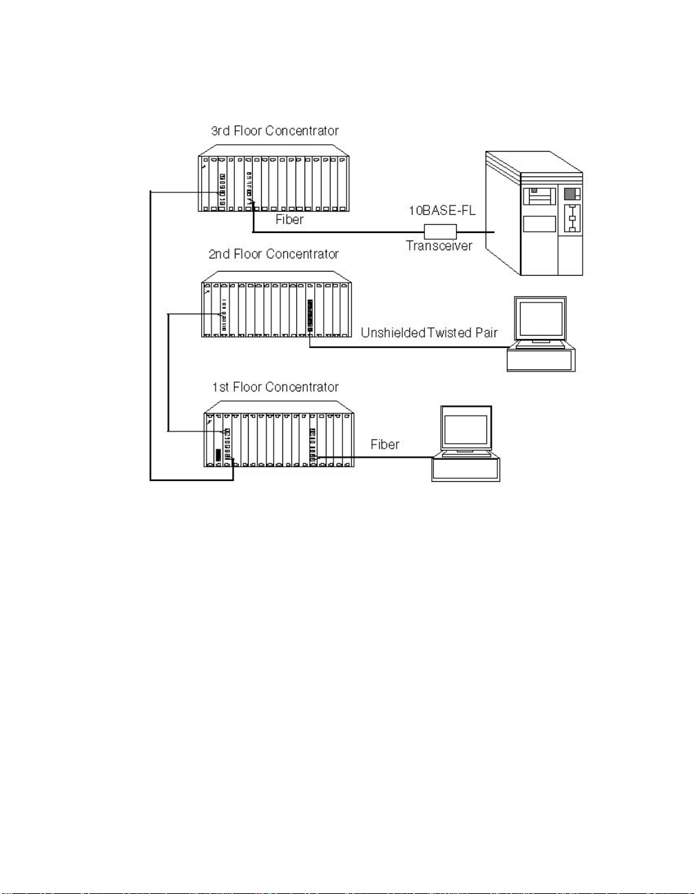
10BASE-FL Backbone, 10BASE-FL to-the-Desk
When designing an all-10BASE-FL network, keep the following rules in
mind:
1. Limit the longest ideal path between any two network stations to
4200 meters due to the IEEE slottime of 51.2 µsec.
2. Limit the length of an 10BASE-FL segment by the optical budget of
the link and the overall size of the netwo rk. The 802.3 10BASE-FL
specification sets 10BASE-FL link distances to 2 km. However , you can
generally extend the length if you compute the optical budget and
take end-to-end timing into consideration.
3. Each 10BASE-FL Module in a serial path between the two transceivers
reduces the maximum cable distance between them by 560 meters
(1836 feet). To be accurate, the equivalent fiber distance is:
❑ 330 meters for signals that externally enter a 10BASE-FL Module
port and go through the backplane
❑ 230 meters for signals that internally enter a 10BASE-FL Module
using the ONline Concentrator backplane
❑ 560 meters for signals that extern ally enter and then exit the
same 10BASE-FL M od ule
For simplicity, use 560 meters per 10BASE-FL Module in the path,
regardless of the signal's direction, when calculati ng fiber equivalent
distances. Note, however, that this limits the network diameter to less
than the maximum size.
2 - 16 ONline Ethernet 10BASE-FL Installation and Operation Guide
Page 39

4. Each 10BASE-FL Module counts as one half of a repeater. The 802.3
specification limits the number of repeaters between any two
network stations to 4. This restricts the number of serially-connected
10BASE-FL Mo dules to a maximum of 8.
Note: The Ethernet 4-repeater rule limits the number of repeaters
between any two transceivers to 4. In general, this restricts
most vendor con figurations to a ma ximum of 4
concentrators connected in series.
5. Rule number 1 does not include AUI cables of up to 50 meters. Thus,
the total network diameter between 10BASE-FL Ethernet nodes can
be 3740 meters (4200 m - 560 m + 50 m + 50 m = 3740 m) through a
single concentrator.
Figure 2-5 shows an example of an all-10BASE-F L network
.
Con centrator A
Concentrator B
500 m
A
T ransceiver
500 m ?
Con cen trator C
1 km
B
Transceiver
Figure 2-5. All-10BASE-FL Network with 3 Concentrators
Designing and Expanding the Network 2 - 17
Page 40

Network Distance Calculation Examples
The following examples demonstrate how to calculate network distances
for various all-10BASE-FL networks.
Example: A Network with 3 Concentrators
Refer to Figure 2-5, which shows a network with 3 concentrators.
T o determine the maximum allowable link distance between Concentrators
A and C:
1. Begin with 4200 meters (Ethernet Rule 3).
2. Subtract the fiber equivalent of the three concentrators with
10BASE-FL Modules that occur on the path between the two
transceivers:
3 * 560 meters for each 10BASE-FL module = 1680 meters (Ethernet
Rule 4)
3. Subtract the known amount of fiber cable between the two
transceivers:
500 m + 500 m + 1 km = 2 km (Ethernet Rule 5)
4. The remainder is the max im um allowable distance of the link
between concentrators A and C:
4200 m - 1680 m - 2000 m = 520 meters
5. Verify that the optical power budget is able to drive all of the link
distances in the example. Because all link distances are only 1 km or
less, and do not have any splices, this is not a problem.
Example: A Network with 6 Concentrators
Six concentrators are connected in Figure 2-6. Use this example to
determine if the distances between transceivers are all within the 4200
meter maximum network diameter restriction for Ethernet netw orks.
2 - 18 ONline Ethernet 10BASE-FL Installation and Operation Guide
Page 41

.
100m
500m
Conc A Conc B
10BASE-FL
Transceivers
Transceivers
500m
100m
500m
Conc CConc D Conc E
Conc F
Transceivers
200m
1km
Transceivers
100m
100m
Note: All 10BASE-FL Transceiver connections to concentrators
(each populated with 10BASE-FL Modules) are 100 meters of fiber.
Figure 2-6. Network with 6 Concentrators
In this example, the path between transceivers attaching Concentrators A
and F has the greatest fiber equivalent distance of 4440 meters (2200 + (4
* 560) = 4440). Because this distan ce exceeds the maximum of 4200
meters, this configuration is illegal and results in improper network
operation.
Designing and Expanding the Network 2 - 19
Page 42

Because it is not always obvious which path between transceivers has the
greatest fiber equivalent distance, use Table 2-6 to help you determine the
equivalent distances.
Table 2-6. Fiber Equivalent Distances Between Transceivers
Total F i ber
Distance
Path
A-D 1700 4 2240 3940
A-E 1400 4 2240 3640
A-F 2200 4 2240 4440
D-E 900 3 1680 2580
D-F 1700 3 1680 3380
F-E 1400 3 1680 3080
Betwee n
Transceivers
(meters)
Number o f
Concentrators
(10BASE-FL
Modules)
Between
Transceiv ers
Equi valent
Fiber
Distance of
Concentrator
(meters)
Total
Fiber
Equivalent
Distance
(meters)
10BASE-FL Backbone, Unshielded Twisted Pair to-the-Desk
Designing a network with unshielded tw isted pair cabling to-th e-desk is
similar to an all-10BASE-FL network because the cabling is star-wired in both
cases (see Figure 2-7). See the section in this chapter “10BASE-FL Backbone,
10BASE-FL to-the-Desk” for more information on all-10BASE-FL networks.
2 - 20 ONline Ethernet 10BASE-FL Installation and Operation Guide
Page 43

Be aware of the following tw o additional rules:
❑ Ensure that there are no more than eight 10BASE-FL Modules (and/or
10BASE-T Modules) in the path between any two transceivers due to
Ethernet's 4-repeater rule (each 10BASE-FL and 10BASE-T Module
counts as a 1/2 repeater). If you have more th an eight modules
serially connected, you must add a bridge.
❑ 10BASE-T Modules have an equivalent fiber distance (see Ethernet
Rule 4) as follows:
– 420 meters for signals that externally enter a 10BASE-T
Module port
– 165 meters for signals that internally enter a 10BASE-T
Module via the ONline Concentrator backplane
For each pair of 10BASE-T Modules that a signal goes through, there is a
fiber equivalent distance of 585 meters (420 m + 165 m =585 m). In
addition, if a signal makes a roundtrip through a 10BASE-T Module (that is,
enters a 10BASE-T port externally and exits through another port on the
same 10BASE-T Module), that counts as 585 meters of fiber equivalent
distance.
Example: Sample Configuration Distance Calculation
Use the following example to determine if the 10BASE-T Transceivers in
Figure 2-7 are within legal Ethernet limits. Identify the two transceivers that
are likely to be the greatest fiber equivalent apart in Figure 2-7. In this case,
they are 10BASE-T Transceivers A and B.
Designing and Expanding the Network 2 - 21
Page 44

.
10BASE-FL Module
Concentrator A
1000 m
230 m
10BASE-FL Module
Concentrator B
330 m
10BASE-FL Module
500 m
Concentrator C
560 m
- 10BASE-T Module
150 m
10BASE-T Module
Unshielded Twisted Pair
A
10BASE-T Mo dule
Unshielded T wisted Pair
75 m
B
Unshielded Twisted Pair
C
Maximum
1.
Diameter
10BASE-FL2.
Modules = 1120 m
Equivalent Distance
3.
10BASE-T
Modules
Equivalent Distance
Distances Between
4.
Transceivers
A & B
Remaining
Distance
2 m x 560 m
150 m + 1000 m
500 m + 75 m
= 1725 m
Figure 2-7. Sample Configuration Distance Calculation
To make the configuration in Figure 2-7 work, ensure the fiber equivalent
distance between transceiver A and transceiver B is less than 4200 meters.
To determine if t he network configuration is legal:
1. Use 4200 meters as the maximum network diameter for a pure fiber
network as defined by th e 802.3 specifi catio n .
4200 m
585 m
770 m
2. Subtract the equivalent fiber distance for each intervening ONline
Concentrator with a 10BASE-FL Module in the path. Figure 2-7 has
three concentrators between the two 10BASE-T T ransceivers A and B
(Rule 4). The signal transverses three 10BASE-FL Modules from a
delay perspective (230 m on Concentrato r A + 560 m on
Concentrator C + 330 m on Concentrator B = 1120 m).
3. Subtract the fiber equivalent distance for the two 10BASE-T Modules
in Concentrators A and B between the two 10BASE-T T ransceivers A
and B (Rule 4).
2 - 22 ONline Ethernet 10BASE-FL Installation and Operation Guide
Page 45

❑ Incoming signal from Transceiver A to the 10BASE-T Module =
420 m.
❑ Outgoing signal from the 10BASE-T Module to Transceiver B =
165 m (420 m + 165 m = 585 m).
4. Subtract all cable lengths between the two transceivers (calculate
copper length the same way you do for fiber). In this example, the
total cable distance equals 1725 meters.
If the result from step 4 is greater than zero, the configuration is
within legal Ethernet limits (Rule 5).
The calculation in this example shows that 770 m eters remain fo r
expansion in this configuration. Therefore, this configuration is legal.
10BASE-FB Fiber Backbone, 10BASE-FL to-the-Desk
Use the information in this section when designing your networ k using
10BASE-FB fiber as the network b ackbone and 10BASE-FL Modules for
to-the-desk connectivity. This section assumes that the backbone is
comprised of 3C om fiber products, such as the ONline Ethernet Fiber
Module or ONline Ethernet 10BASE-FB Module. 3Com Ethe rnet Fiber
modules and transceivers conform to the IEEE 10BASE-F standard.
The rules that apply to building this type of network have been covered in
the previous sections. The following two additional rules apply when using
ONline Ethernet Fiber Modu les:
1. The equivalent fiber distance for the Fiber Module and the
Port-Switching Fiber Module is:
– 140 meters for signals that externally enter the module
– 50 meters for signals that internally enter the module
through the ON line Concentrator backplane
Designing and Expanding the Network 2 - 23
Page 46

.
Therefore, for each pair of ONline Fiber Modules that a signal passes
through, there is a fiber equivalent distance of 190 meters (140 m +
50 m = 190 m). In addition, a signal making a round trip through the
module (that i s, en tering a port externall y and exiting through
another port on the same module) counts as 190 meters of fiber
equivalent distance.
2. Do not count the ONline Ethernet Fiber Module and the ONline
Ethernet Port-Switching Fiber Module as repeaters when determining
the maximum number of repeaters in your network. These are
repeater-less devices.
Example: Fiber Backbone, 10BASE-FL to-the-Desk
Use the following example to determine if the 10BASE-FL transceivers ar e
within legal Ethernet limits. First identify the two transceivers that are likely
to be the greatest distance apart in Figure 2-8. In this case, they are
10BASE-FL transceivers A and B
Concentrator A
Fiber Module
1000 m
Concentrator B
10BASE-FL Module
500 m
Concentrator C
Fiber Module
10BASE-FL Module
450 m
10BASE-FL
75 m
10BASE-FL
50 m
B
C
10BASE-FL
A
Maximum
1.
Diameter
FL2.
330 m + 230 m
Modules = 560 m
Equivalent Distance
Fiber 50 m+190 m+140 m
3.
Modules = 380 m
Equivalent Distance
Cable Distance
4.
(450 m + 1000 m +
500 m + 75 m)
Remaining
Distance
Figure 2-8. Sample Fiber Backbone, 10BASE-FL to-the-Desk
Configuration
2 - 24 ONline Ethernet 10BASE-FL Installation and Operation Guide
4200 m
2025 m
1235 m
Page 47

To determin e if t he network configuration in Figure 2-8 is leg al :
1. Use 4200 meters as the maximum network diameter as defined by
the 802.3 specification.
2. Subtract the equivalent fiber distance for each 10BASE-FL Module in
the signal path between T ransceivers A and B. This equals 330 meters
for Concentrator A and 230 meters for Concentrator B (560 meters
total).
3. Subtract the equivalent fiber distance for each Fiber or Port-Switching
Fiber Module in th e signal path. This equals 50 meters for
Concentrator A, 190 meters for Concentrator C, and 140 meters for
Concentrator B (380 meters total).
4. Subtract all fiber cable lengths between the transceivers (450 m +
1000 m + 500 m + 75 m = 2025 meters).
Because the final remaining distance is greater than zero (1235
meters), the network configuration is legal.
Connecting Extern al Netwo rk Devices
When connecting Thick or Thin Ethernet segments to an ONline network,
you can use an:
❑ ONline Ethernet Repeater Module
❑ ONline Ethernet Bridge Module
❑ External repeater or bridge
❑ An IEEE Repeater or ONline Repeater Module each have an
equivalent fiber distance of 800 meters
Designing and Expanding the Network 2 - 25
Page 48

Example: Connecting a Thin Ethernet (10BASE2 ) Segment
Figure 2-9 shows a typical Thin Ethernet segment connected to an ONline
Concentrator th rough an I E EE 802.3 Repeater
.
10BASE-FL Module
10BASE-FL
Backbone
185 m
Coaxial10BASE-FL
Transceiver
A
1500 m
10BASE-T Module
10BASE-FL Module
200 m
Transceiver
5101T-FL
50 m
Transceiver Cable
10BASE-T Transceiver (5101T-TP)
100 m
B
IEEE
Repeater
Thin Ethernet
Figure 2-9. Thin Ethernet Segment Connecting to ONline Using an
IEEE Repeater
To determine if the configuration in Figure 2-9 meets Ethernet distance
limitations for transceivers A and B:
1. Use 4200 meters as the maximum network diameter as defined by
the 802.3 specification.
2. Subtract the fiber equivalent distance of 420 m for the signal
externally entering the 10BASE-T Module from T ransceiver B and 230
meters for the signal exiting the 10BASE-FL Module within the same
concentrator. (Ethernet Rule 4)
3. Subtract the fiber equivalent distance of 560 meters for the signal
externally entering the 10BASE-FL Module in the top concentrator,
and internally exiting a different port on the same 10BASE-FL Module.
4. Subtract the fiber equivalent distance (800 m) of the IEEE Repeater.
(Ethernet Rule 4)
2 - 26 ONline Ethernet 10BASE-FL Installation and Operation Guide
Page 49

Note: In the reverse direction, a signal originating at Transceiver
A loses 165 m of fiber equivalent distance when it exits the
10BASE-T Module to which T ransceiver B is connected and
330 meters for the signal entering the 10BASE-FL Module in
the bottom concentrator. The overall fiber equivalence of
the path is greater for signals going from T ransceiver B to
A, however, the B to A f iber equivalence determines
whether the link meets the 4200 m Ethernet link maximum.
5. Subtract the sum of intervening cable lengths:
185 m + 50 m + 200 m + 1500 m + 100 m = 2035 m
6. The remainder is:
4200 m - 420 m - 230 m - 560 m - 800 m - 2035 m = 155 m
Because the remaining value is greater than zero, the configuration in
Figure 2-9 is legal.
Designing and Expanding the Network 2 - 27
Page 50

Fault-Tolerant Configurations
This section contains descriptions of the redundancy features built into the
ONline 10BASE-FL Module. Y ou can implement link redundancy between
concentrators using the port redundancy switch settings on the 10BASE-FL
Module.
This section contains the following topics:
❑ Configurin g Ports for Fault Tolerance
❑ Implemen ting Backbone Cable Plant Fault Tolerance
❑ Implemen ting Total Backbone Fault Tolerance
Configuring Ports for Fault Tolerance
You can configure ports 1 through 4 on the 10BASE-FL Module in one of
five ways:
❑ Normal Configuration - Ports 1 through 4 operate as independent
cable ports.
❑ Standard Redundant Configuration - In this configuration:
– Port 1 acts as the primary port and port 2 as the backup
for 1.
– Port 3 acts as the primary port and port 4 as the backup
for 3.
❑ Flexible Redundant Configuration - You can arbitrarily assign
primary and backup ports to any pair of ports. Y ou can configure this
mode only through a network management module.
❑ Normal and Redundant Configuration - You can enable
redundancy between one set of ports and configure the remaining
two ports to operate as independent ports.
2 - 28 ONline Ethernet 10BASE-FL Installation and Operation Guide
Page 51

❑ Remote Failure Signaling Configuration - If redundancy is enabled
at the other end of the fiber link, you must enable remote failure
signaling for all connecting 10BASE-FL Module ports.
Implementing Backbone Cable Plant Fault Tolerance
Y ou can enable redundancy between two ports on the 10BASE-FL Module
using either:
❑ Network management module commands
❑ A dip switch
This section describes:
❑ Setting Redundancy
❑ Remote Failure Signalling
Setting Red undancy
When you enable redundancy betw een two ports, the ports are
automatically enabled. Port 1 (or 3) then becomes the primary link and port
2 (or 4) the redundant link. Fo r m aximum cable plant fault tolerance,
connect both the primary and backup ports back to the central
concentrator (Figure 2-10). This configuration allows the backup port to
automatically take over if the primary link fails.
Designing and Expanding the Network 2 - 29
Page 52

Redundancy
Primary
10BASE-FL
Link
Enabled
Redundancy
Enabled
Primary B ackup
Ba ckup
10BASE-FL
Link
Redundancy Disabled
(Remote Failure Signaling
enabled for port 4 on each
10BASE-FL Module)
Figure 2-10. Redundant Fiber Backbone Configuration
Note: Always enable redundancy in the lower level concentrators
(those connectin g to the central concen trators in the
star-wired topology).
The primary port passes data. The backup port does not pass any data in
either direction, but the link is monitored for any failures (the Port Status
LED indicates any problems).
2 - 30 ONline Ethernet 10BASE-FL Installation and Operation Guide
Page 53

Remote Failure Signaling
In any redundant link path, you can designate (that is, activate) only one
end as a redundant port pair (1-2 or 3-4). Y ou must enable remote failure
signaling (RFS) if ports are connected to fiber with redundancy enabled at
the other end. If you enable ports at both ends as redundant, or if you do
not enable remote failure signaling at the distant end, improper operation
of the redundant switchover mechanism occurs (see Figure 2-11).
If the primary link experiences a local or remote fault, the backup link
activates and the primary ports disconnect (that is, they do not pass data to
and from the con centrator). Once the switchover to backup occ urs, the
redundancy status indicators blink at the redundant module end. However ,
primary port diagnostics continue to operate. If the fault clears, the primary
port is re-enabled.
Each redundancy status LED (located beneath the Activity LEDs):
❑ Is off - If you disable redundancy.
❑ Is on - If you enable redundancy and both ports are operational.
❑ Blinks - If a switchover occu rs due to a link failure.
Designing and Expanding the Network 2 - 31
Page 54

Implementing Total Backbone Fault Tolerance
You can add a backup ONline System Concentrator to provide total
backbone fault tolerance and link redundancy for your backbone network.
As shown in Figure 2-11, if the primary concentrator or any primary links
fail, the backup concentrator takes over. In this configuration:
❑ One port on the 10BASE-FL Modules connects to the primary
concentrator.
❑ The other port connects to the backup concentrator.
You must also hav e a direct connection between th e two concentrator s
Redundancy
Enabled
Primary
Fiber
Link
Backup
Fiber
Link
Redundancy
Enabled
Redu ndancy Disabled
(Rem ote F ailure Signaling
enabled for port 4 on ea ch
10BASE-FL Module)
Figure 2-11. Total Backbone Fau lt-Tolerant Configuration
2 - 32 ONline Ethernet 10BASE-FL Installation and Operation Guide
Page 55

Example: Network with Three Concentrators and a Fourth
Concentrator in Full Redundancy Configuration
In the following example, three concentrators are active.
Concen trator A
500 m
1 km
500 m
10BASE-FL Transceiv er s
500 m
1 km
Concen trator DConcen trator C
Transceivers
Concentrator B
500 m
10BASE-FL
500 m
Fiber cable
Primary Link
Backup Link
Normal Link
Figure 2-12. Network With 3 Concentrators
Concentrator B is a redundant concentrator for Concentrator A. The fiber
equivalent distance between transceivers attached to Concentrators C and
D is:
3 * 560 m + 500 m + 1000 m + 500 m + 500 m = 4180 meters
Because the sum is less than 4200 meters, the configuration is legal.
Designing and Expanding the Network 2 - 33
Page 56

In Figure 2-12, if the main li nk from Concentrator A to Concentrator C
faults, the signal path enabled through redundancy includes Concentrator
B. By adding Concentrator B, the fiber equivalent d istance becomes too
great and the network cannot work b ecause the path between
Concentrators C and D is C-B-A-D:
4 * 560 + 500 m + 1000 m + 500 m + 500 m + 500 m = 5240 meters
Because the sum i s greater than 4200 meters, this configuration is not
legal. When designing a redundant network, be sure to consider the
backup route distance.
2 - 34 ONline Ethernet 10BASE-FL Installation and Operation Guide
Page 57

3
Installing and
Operating the Module
This chapter describes the installation procedures for the ONline Ethernet
10BASE-FL Module.
For your convenience, a quick reference installation chart is included. This
chapter includes the following sections:
❑ Precautionary Procedures
❑ Unpacking Procedures
❑ Quick Installation
❑ Setting the Dip Switches
❑ Installing the Module
❑ Config uring the Module
❑ Showing Module Configuration
❑ Monitoring the Front Panel
❑ Verifying the LEDs and Network Assignments
Note: Read the precautionary procedures before unpacking the
module.
Installing and Operating the Module 3 - 1
Page 58

Precautionary Procedures
Electrostatic discharge (ESD) can damage static-sensitive devices on circuit
boards. Follow these precautions when you handle the 10BASE-FL Module:
❑ Do not remove the board from its anti-static shielding bag until you
are ready to inspect it.
❑ Handle the board by the faceplate only.
❑ Use proper grounding techniques when you install the 10 BASE-FL
Module. These techniques include:
– Using a foot strap and grounded mat or wearing a
grounded static discharge wrist strap.
– Touching the grounded rack or other source of ground
just before you handle the 10BA SE-FL Module.
Unpacking Procedures
When unpacking your 10BASE-FL Module:
1. Verify that the 10BASE-FL Module is the correct model by matching
the model number listed on the side of the shippin g carton to the
model numb er y ou ordered (Model Number 5104M-FL1).
Note that the product model number printed on the shipping box
differs from the model number on the product. The model number
on the shipping box contains the prefix ’3C9’.
2. Remove the 10BASE-FL Module from the shipping carton.
3. Remove the 10BASE-FL Module from the anti-static shielding bag and
inspect the mod ule for damage. If the modu l e appears to be
damaged, replace it in the anti-static shielding bag, return it to the
shipping c arton, and contac t your local supplier.
3 - 2 ONline Ethernet 10BASE-FL Inst allation and Operation Guide
Page 59

4. Keep the carton and anti-static bag in which your module was
shipped for repackagi ng the module for st orage or shipment.
5. Record the serial number of your 10BASE-FL Module. A log and other
information specific to your modules is included in the ONline System
Concentrator Installation and Operation Guide, Appendi x B , Slot
Usage Chart.
Quick Install atio n
Table 3-1 outlines the steps for installing your module.
Table 3-1. Quick Installation Proce dures
Step Procedure Section Title
1. Verify that your network complies with
basic rules for network design.
2. Unpack the module. Unpacking
3. If you do not have a management
module installed in t he concentrator,
configure the dip switch settings to your
specifications.
4. Insert the module into a blank slot in the
concentrator and tighten the faceplate
screws.
5. Establish connections from the
10BASE-FL Module to another 10BASE-FL
Module or 10BASE-FL T ransceiver using
the appropriate connectors and cabling.
Chapter 2, Designing
and Expanding the
Network
Procedures
Setting the Dip
Switches
Installing the Module
Installing the Module
Installing and Operating the Module 3 - 3
Page 60

Table 3-1. Quick Installation Procedures (Continued)
Step Procedure Section Title
6. If you have a management mod ule
installed in the concentrator, configure
the module using the managemen t
commands.
7. Verify LED status for normal operation. Verifying LED and
Setting the Dip Switches
The 10BASE-FL M odule has two 8-position dip switches (SW1 an d SW2)
located on the rear of the board. Figure 3-1 shows the location and default
settings of the SW1 and SW2 dip switches. You may need to reconfigure
one or more of these switches depen ding on your configuration
requirements.
The dip switch settin gs for the 10BASE-FL Module are ignored if an
appropriate ONline management module is installed in the concen trator.
For this reason, use the management commands (rather than the dip
switches) to configure the 10BASE-FL M odule. If you have an installed
Ethernet Management Module (EMM) at Version 4.01 or higher , install the
module first and then refer to the Configuring the Module section in this
chapter for m o re information.
Configuring the
Module
Network Assignments
The remainder of this section describes:
❑ Setting Dip Switch SW1
❑ Setting Dip Switch SW2
3 - 4 ONline Ethernet 10BASE-FL Inst allation and Operation Guide
Page 61

AAAA
AAAA
Port 1
Port 2
Port3
Port4
Redun
1-2
Redun
3-4
Port 1
Port 2
Port 3
Port 4
AAA
AAA
PRTEN4
PRTEN3
PRTEN2
PRTEN1
SPARE
SPARE
RED34
RED12
RFS4
RFS3
RFS2
RFS1
ON
1 2 3 4 5 6 7 8 1 2 3 4 5 6 7 8
Channel Selection Switches
CH A B
1 On On
2 On Off
3 Off On
Isolate d Off Off
Backplane DIN
Connector
Figure 3-1. 10BASE-FL Module Dip Switch Locations
SPARE
SPARE
CHB
CHA
SW2SW1
Setting Dip Switch SW1
The SW1 dip switch on the 10BASE-FL Modul e co ntains 8 dip switches.
Switches 7 and 8 are not functional. The remaining switches allow you to:
❑ Enable or disable redundancy between ports 1 and 2 or 3 and 4
❑ Enable remote failure signaling for each port
Installing and Operating the Module 3 - 5
Page 62

T able 3-2 lists the functions and settings for switch SW1. For a definition of
each dip switch function, refer to the Con figuring the Module section.
Table 3-2. Dip Switch SW 1 Settings
Switch Label Function
1 RFS1 Enable remote
failure signaling
on port 1
2 RFS2 Enable remote
failure signaling
on port 2
3 RFS3 Enable remote
failure signaling
on port 3
4 RFS4 Enable remote
failure signaling
on port 4
5 RED12 Enable/disable
redundancy
between ports
1 and 2
Factory
Default
disable disable
disable disable
disable disable
disable disable
disable disable
Switch Set ting
Off On
6 RED34 Enable/disable
redundancy
between ports
3 and 4
7 and 8 SPARE Not used
3 - 6 ONline Ethernet 10BASE-FL Inst allation and Operation Guide
disable disable
Page 63

Setting Dip Switch SW2
The SW2 dip switch on the 10BASE-FL Modul e co ntains 8 dip switches.
Switches 7 and 8 are not functional. The remaining switches allow you to:
❑ Enable or disable e ach of t he ports
❑ Assign the m odule to a channel
Table 3-3 lists the functions and settings for switches 1 through 4. For a
definition of each dip switch function, refer to the Configuring the Module
section in this chapter..
Table 3-3. Dip Switch SW 2 Settings for Switches 1 to 4
Switch Function Factory D efault
1 Enable/Disable port 1 Enable (On)
2 Enable/Disable port 2 Enable (On)
3 Enable/Disable port 3 Enable (On)
4 Enable/Disable port 4 Enable (On)
Installing and Operating the Module 3 - 7
Page 64

Table 3-4 lists the functions and settings for switches 5 and 6. For a
definition of each dip switch function, refer to the Configuring the Module
section in this chapter.
Table 3-4. Dip Switch SW 2 Settings for Switches 5 and 6
CHA CHB Channel Selection
Switch Settings
Installing the Module
Y ou do not need to power down the ONline System Concentrator to install
the 10BASE-FL Module. You can insert the module while the concentrator is
operating (this is called a hot swap).
To install the module:
1. Do one of the following:
❑ If you do not have a management module installed in the
concentrator, set the dip switches on the board (if different from
the default settings). After you complete the installation
procedure, proceed to the Monitoring the Front Panel section to
verify the installation.
On On 1 (factory default)
On Off 2
Off On 3
Off Off Isolated (module operates
independent of any backplane
channel)
❑ If you have a management module installed in the concentrator,
complete this installation procedure and then configure the
module using the commands as described in the Configuring the
Module section.
3 - 8 ONline Ethernet 10BASE-FL Inst allation and Operation Guide
Page 65

2. Locate a blank slot in the concentrator. If there is no blank slot,
remove a blank panel on the concen trator to expose a slot for the
10BASE-FL Module.
3. Insert the module into the board guides at the top and bottom of the
slot and slide it into the concentrator . Make sure that the connector is
well seated into the backplane of the concentrator.
Figure 3-2 shows the installation of the 10BA SE-FL Module
.
Figure 3-2. Installing the 10BASE-FL Module
4. Fasten the spring-loaded screws on the front of the 10BASE-F L
Module faceplate to th e concentrator using your fingers (do not
overtighten).
5. Remove the plastic fiber optic dust covers from the cable ports. Keep
unused cable ports capped to keep the optics clean.
6. Attach the fiber cables to the fiber ports on th e front of the
10BASE-FL Module as shown in Figure 3-3.
Installing and Operating the Module 3 - 9
Page 66

Figure 3-3. 10BASE-FL Module Connection
7. Make sure that the transmit and receive cables are:
❑ Clearly marked or color coded.
❑ Connected to the appropriate ports on the 10BASE-FL Module.
❑ Properly cleaned with an appropriate fiber optic cleaning solution
before installation.
Note: Do not exceed the b end radius for the fiber cable when
directing the cables under the conc entrator. Refer to the
cable manufacturer's specifications for minimum bend
radius.
8. Attach the other ends of the cables to either:
❑ Another ONline 10BASE-FL Module.
❑ An ONline 10BASE-FL Transceiver.
3 - 10 ONline Ethernet 10BASE-FL Installation and Operation Guide
Page 67

Make sure that the transmit fiber at one end always connects to a receive
port at the other end.
Caution: Do not connect the 10BASE-FL Mo dule to an ONline
Ethernet Fiber Module, to a 10BASE-FB module, or to
any other module or transceiver that is not
FOIRL-compatible or 10BASE-FL-compliant. These illegal
connections may cause network failure.
Configuring the Module
The ONline management modules can configure the following settings on
the 10BASE-FL Module:
❑ Enable/disable any port on the module
❑ Set the module to a network
❑ Enable redundancy betw een two ports
❑ Enable remote failure signaling for any port
The following ONline management modules provide network management
capabilities for the O Nline System Conc entrator and its modules:
❑ Ethernet Management Module V3.20
❑ Token Ring Management Module V3.00
❑ FDDI Management Module V1.01
When an ONline management module is installed in a concentrator , all of
the dip switch settings on the 10BASE-FL Module are overrid den.
Installing and Op erating the Module 3 - 11
Page 68

When you first install the module:
1. The network (channel) defaults to isolated mode . The ports are
automatically disabled so that unapproved users cannot be added.
Therefore, you must enable the p orts you wish to use and set the
module to the appropriate Ethernet netw ork through the
management commands.
2. All other module settings retain the same default values as the dip
switch default values. Therefore, you only change these values
through manag ement if you do not want the default values.
This section describes the management comm ands to set these features.
For additional information on the available network management features,
refer to:
❑ The appropriate ONline Management Module Installation and
Operation Guide
❑ ONline Manag em ent C om mands Guide
Enab ling Port s
You can enable or disable each of the four ports on the module. When a
port is enabled, it can transmit data onto and receive data from the
network to which the m od ule is assigned .
To enable or disable a specific port, use the following management
command:
SET PORT {
slot.p or t
{
slot.
} MODE {enable}
all} {disable}
3 - 12 ONline Ethernet 10BASE-FL Installation and Operation Guide
Page 69

Selecting a Network
The ONline 10BASE-FL Module is equipped with the technology to work
with the ONline Concentrator's unique TriChannel™ Architecture. This
feature lets you assign the module to any of three networks (or none) on
the ONline System Concentrator backplane. Refer to the ONline System
Concentrator Installation and Operation Guide, Chapter 1, for a discussion
of the ONline TriChannel Architecture.
To set the module to a network or set it to isolated mode, use the
following management command:
SET MODULE {
slot
} NETWORK {ethern et_ 1}
Note: The dip switch settings on the m od ule refer to the
backplane connection as the “channel” connection. The
channel setting and the network setting are the same.
Modules set to the same network communicate with each
other .
Enab ling Port Redund ancy
{ethern et_ 2}
{ethern et_ 3}
{isolat ed}
You can enable por t redundancy in one of the following ways:
❑ If you have network management, you can enable or disable main
port redundancy between any two ports on the 10BASE-FL Module.
❑ If you do not have management, you can use the dip switches on the
module to configure redundancy between ports 1 and 2 on the
module and/or por t s 3 and 4.
Installing and Op erating the Module 3 - 13
Page 70

For example, when you enable redundancy:
1. Port 1 becomes the primary link and port 2 is the redundant link.
2. If the primary link (port 1) fails, the redundant link (port 2) is engaged
automatically, thus preventing a network failure.
3. When you disable redundancy, each port works independently.
Note: Enabling port redundancy for two ports automatically
enables the ports themselves, even if the ports were
previously disabled.
The redundancy status LEDs, located between the sets of port LEDs and the
port connec tors on the 10BASE-FL Module, are:
❑ Off - When you disable redundancy (default setting).
❑ On - When you enable redundancy.
For information about the redundancy LEDs, refer to Table 3-5.
To set redundancy between ports, use the following management
command:
SET PORT {
slot.port
} MODE REDUNDANT {
slot.port
}
To turn off redundancy between ports, use the MODE NON_REDUNDANT
option. Redundancy configurations are shown in Chapter 2, Designing and
Expanding the Network.
Note: If you enable redundancy on one end of a link, you must
enable Remote Failure Signaling (RFS) at the other end. For
more information, refer to the next section, Enabling
Remote Failure Signaling.
3 - 14 ONline Ethernet 10BASE-FL Installation and Operation Guide
Page 71

Enabling Remote Failu re Signal ing
Due to the nature of the 10BASE-FL standard, the receive path of a
redundant port can detect no light and partition errors, but the transmit
path cannot detect these errors. Remote Failure Signaling (RFS) provides a
way for transmit failures to be detected so that a switchover from a
primary to a backup port can occur. Y ou can enable RFS for any of the four
ports on your module. When you connect two 10BASE-FL Modules and
enable redundancy between two ports on one of the modules, you must
enable RFS on the corresponding ports of the other module.
For example, if you enable redundancy between p orts 1 and 2 on
10BASE-FL Module #1 and these ports are connected to ports 1 a nd 2 on
Module #2, you must enable RFS on ports 1 and 2 on 10BASE-FL Module
#2 (Figure 3-4). Note that RFS is automatically disabled when you disable
redundancy on the corresponding port or disable the port.
.
Figure 3-4. 10BASE-FL Modules Connected with Redundancy/RFS
Enabled
Installing and Op erating the Module 3 - 15
Page 72

To enable RFS for a port, issue the following management command:
SET PORT {
slot.port
} MODE REMOTE_FAILURE_SIGNALING
Saving Modu le Co nfig uratio n
To save the module and port settings to management module memory,
issue the following command:
SAVE MODULE_PORT
Showing Mo du le Configu ratio n
Y ou can display status information about the 10BASE-FL Module using the
following commands:
❑ SHOW MODULE
❑ SHOW MODULE VERBOSE
❑ SHOW PORT
❑ SHOW PORT VERBOSE
For example, the following command displays detailed information about
port 1 on an 10BASE-FL Module in slot 6 of the concentrator.
ONline> show port 6.1 verbose [ENTER]
Port Display for Module 5104M-FL
Port Mode Status Network General In fo rma ti on
06.01 ENABLED OKAY ISOLATED
Port Connect or FIBER
Mode Di p S et tin g: ENABLED
3 - 16 ONline Ethernet 10BASE-FL Installation and Operation Guide
Page 73

This display tells you the status of the specific port. It includes the
management module and dip switch settings from the board. For m ore
inform ation on the SHOW commands, refer to the:
❑ Appropriate ONline Management Module Installation and Operation
Guide
❑ ONline Management Commands Guide
Monitorin g the Front Panel
The LEDs on the front panel of the 10BASE-FL Module allow you to monitor
the status of each port. The 10BASE-FL Module has 10 LEDs on the front
panel that allow you to monitor diagnostic, activity , and redundancy status
for each port.
Figure 3-5 shows the location of these indicato r s
Installing and Op erating the Module 3 - 17
Page 74

.
Figure 3-5. 10BASE-FL Module Faceplate and ONline System
Concentrator
3 - 18 ONline Ethernet 10BASE-FL Installation and Operation Guide
Page 75

Table 3-5 describes how to interp ret the 10BASE-FL Module LEDs.
Table 3-5. Interpretin g the 10BASE-FL Module LEDs
LED Name Color State Indicates
Activity Yellow Off No packets are received on
the fiber segment.
(Ports 1-4) On Constant activity on the fiber
segme nt.
Blinking Module receives packets
from segment to which it is
attached.
Status Green Off Port disabled.
(Ports 1-4) On Port enabled or in standby
and link integrity is OK.
1 blink No light detected.
2 blinks Port partitioned.
Redundancy
(Ports 1&2)
(Ports 3&4)
3 blinks FIFO error or MAU jabber
lockup protection.
Green Off Redundancy is disabled;
ports are independent of
each other.
On Redundancy is enabled
between ports 1 and 2
and/or 3 and 4.
Blinking Redundanc y is enabled
between ports 1 and 2
and/or 3 and 4 and there is
a failure on one of these
ports.
Installing and Op erating the Module 3 - 19
Page 76

Verifying the LED and Network Assignments
Once you install the module, verify its operation through the front panel of
the ONline Controller Module. The Controller Module is equipped with an
LED check button on the front panel. Use the LED check button to:
❑ Verify LED operation
❑ V erify network (channel) assignment
When you press this button, the Controller Module initiates a test to all
modules in the con centrator. All LEDs should respond by lighting
continuously for approximately five seconds. Any LED that does not light is
defective.
After the 5 seconds elapse, the diagnostic continues with a network
(channel) check of all modules. Each Status LED should respond by blinking
the number of times to correspond with the network to which the module
is assigned. The network check sequence repeats five times. Table 3-6
explains the network check codes.
Table 3-6. Network Check Codes
LED State Module Is Configu red fo r...
1 Blink Network 1
2 Blinks Network 2
3 Blinks Network 3
Off Isolated mode (operates independent of any network)
3 - 20 ONline Ethernet 10BASE-FL Installation and Operation Guide
Page 77

4
Troubleshooting
This chapter describes fault conditions and troubleshooting suggestions for
the 10BASE-FL Module.
This chapter contains the following sections:
❑ Troubleshooting Using the Port Activity LEDs
❑ Troubleshooting Using the Port Status LEDs
❑ RFS Troubleshootin g
❑ Technical Assistance
Note: Do not connect a 10BASE-FL Module to an ONline Ethernet
Fiber Module, fiber transceiver , or any other non-10BASE-FL
compliant or FOIRL- compatible product. ONline fiber
products use 10BASE-FB signaling, which are incompatible
with the 10BASE-FL protocol and FO IRL.
Troubleshooting 4 - 1
Page 78

Troubleshooting Usin g the Port Acti vity LEDs
If a port Activity LED does not light, use the Table 4-1 to help troubleshoot
the problem.
Table 4-1. Troubleshooting Using the Port Activity LEDs
LED Name
Activity
(Ports)
1 - 4)
LED
State
Off There is no traffic
Possible Cause Corrective Action
received from the
segment.
Port is disabled. Enable the port.
Power is off. Check the Controller
Activity LED has burnt
out.
10BASE-FL Module
port is faulty.
10BASE-FL Module is
faulty.
Backplane connection
is bad.
None.
Module Power LED.
Press the LED check
button on the
Controller Module.
Connect the cabl e
to a different port.
Try a different
10BASE-FL Module.
Reinsert the
10BASE-FL Module. If
this fails, try another
concentrator slot.
4 - 2 ONline Ethernet 10BASE-FL Inst allation and Operation Guide
Page 79

Troubleshooting Using the Port Status LEDs
A blinking Port Status ind icator is always a sign that the port detects a
potential problem. Once a port detects a problem, you can further analyze
the problem by counting the number of blinks. Table 4-2 provides
troubleshooting suggestions for each blinking sequence.
Table 4-2. Troubleshooting Using the Port Status LEDs
LED State Indication Possible Cause Corrective Action
Off Port
Disabled
1 Blink No Light
Received
Port disabled. Enable port.
10BASE-FL
Module not
powered.
Broken LED. Press LED check
Bad 10BASE-FL
Module.
Cables crossed. Verify TX on remote
Broken fiber
cable.
Bad fiber
connections.
Check concentrator
power status.
Reinsert 10BASE-FL
Module.
button on Controller
Module.
Replace Module.
device is connected to
RX on 10BASE-FL
Module.
Check and fix RX fiber
link.
Clean and reconnect
fiber (both ends).
Troubleshooting 4 - 3
Page 80

Table 4-2. Troubleshooting Using the Port Status LEDs
LED State Indication Possible Cause Corrective Action
1 Blink
(continued)
2 Blinks Port
No Light
Received
Partitioned
Insufficient
opti cal power
received.
Bad remote
device.
Bad 10BASE-FL
Module.
Bad fiber
connections.
Bad remote
device.
Broken fiber . Check and fix RX fiber
Check 10BASE-FL
Module optical power
using a light meter .
Check optical po wer
of remot e de v i ce.
If optical power levels
are OK, che ck cable; it
may be bad or too
long.
Replace remote device.
Replace module.
Clean and reconnect
fiber (both ends).
Replace remote device.
link.
Bad 10BASE-FL
Module.
3 Blinks FIFO error or
MAU jabber
lockup
protection
4 - 4 ONline Ethernet 10BASE-FL Inst allation and Operation Guide
Check optical
power.
Bad fiber
connections.
Broken or
cracked fiber.
Replace Module.
Verify that optical
power level is correct.
Clean and reconnect
TX fiber (both ends).
Check and fix RX fiber
link.
Page 81

Table 4-2. Troubleshooting Using the Port Status LEDs
LED State Indication Possible Cause Corrective Action
3 Blinks
(continued)
FIFO error or
MAU
jabber
lockup
protection
RFS Troubleshooting
When you enable redundancy for a port on one 10BASE-FL Module
(splices), you must enable Remote Failure Signaling (RFS) on the
corresponding port of the remote 10BASE-FL Module to which it is
connected. If you accidentally enable RFS on both sides of a 10BASE-FL link,
the link may fail because each side “thinks” it is the remote end of the link.
In addition, when you enable redundancy on both sides of a 10BASE-FL link
and the primary port fails, the backup port on the remote end of the link
does not take over because the port “thinks” it is the primary port.
Bad unit or
non-10BASE-FL
equipment at
other end.
Bad 10BASE-FL
Module.
Try another port or
replace other unit.
Replace module.
Technical Assistance
Y ou can receive assistance for installing and troubleshooting the 10BASE-FL
Module by calling either your 3Com reseller or 3Com T echnical Support. Be
prepared to supply a representative with the following informatio n:
❑ Description of the problem
❑ Steps you have tak en to try and correct the problem
❑ T ype and software version of the ONline management module being
used
Troubleshooting 4 - 5
Page 82

❑ Version of software installed on your 10BASE-FL Module
❑ Status of the front panel LEDs
❑ Configuration of your concentrator
(you may find it helpful to refer to the Slot Usage Chart in Appendix B
of the ONline System Concentrator Installation and Operation Guide
for a record of this information)
Refer to Appendix B for instruction s on contactin g Technical Support for
your product .
4 - 6 ONline Ethernet 10BASE-FL Inst allation and Operation Guide
Page 83

A
Specifications
This appendix lists specifications for the 10BASE-FL Module, including:
❑ General Specifications
❑ Optical Specifications
❑ Power Requirements
❑ Environmental Speci fications
❑ Mechanical Spec ifications
❑ 10BASE-FL Cable and Connec tor Specifications
Specifications A - 1
Page 84

General Specific atio ns
Table A-1 lists general specifications for the 10BASE-FL Module.
Table A-1. General Specifications
10BASE-FL Module Model
number
Collision Detection 100% determi nistic
Configuration Rules Compliant with IEEE 802.3 10BASE-FL
Maximum Number of Nodes 1024
Backplane Interface 96-pin edge connector, compatible
External Connec tor 4 pairs of fiber ports (ST, SMA, or FC
Host Interfac e ONline System Co ncentrator bus
Installation Att ac hment Two t humbscrews on the mou nting
5104M-FL1
and FOIRL specifications
with the 3Com ONline System
Concentrator
connectors)
interface standard
bracket
A - 2 ONline Ether net 10BASE-FL Installation and Operation Guide
Page 85

Optical Specifications
This section lists the optical specifications for the 10BASE-FL Module,
including:
❑ Transmitter Specifications
❑ Receiver Specifications
❑ Supported Fiber Optic Cables
❑ Fiber Optic Interface
Transmitter Specifications
Light Source: GaA1As LED at wavelength 820 ± 20 nm. Power coupled
into fiber cable inclusive of ST, SMA, or FC connector loss.
Table A-2 lists transmit power specifications.
Table A-2. Transmit Power (Peak Values)
- 6.5 dBm (± 3.0 dBm ) 100/140 m icron, 0.29 NA fiber
- 9.0 dBm (± 3.0 dBm) 85/125 micron, 0.29 NA fiber
- 12.0 dBm (± 3.0 dBm) 62.5/125 micron, 0.275 NA fiber
- 16.5 dBm (± 3.0 dBm) 50/125 micron, 0.20 N A fiber
Specifications A - 3
Page 86

Receiver Specifications
Table A-3 lists receiver specifications for t he 10BASE-FL Module.
Table A-3. Receiver Specifications
Light Detector Silicon PIN photodiode
Input Range Optical power input of -8.0 dBm to
Bit Error Rate 1 in 10
Dynamic R ange 21.5 dB
Supported Fiber Optic Cables
You can use the following fib er optic cables with the 10BASE-FL Mod ule:
❑ 50/125
❑ 62.5/125
-29.5 dBm (peak values)
-9
over dynamic range
❑ 85/125
❑ 100/140
The fiber optic cable must be:
❑ Micron diameter graded index
❑ Duplex fiber
❑ 150 MHz km rating or better
A - 4 ONline Ether net 10BASE-FL Installation and Operation Guide
Page 87

Fiber Optic Interface
Table A-4 lists specifications for the fiber optic interface.
Table A-4. Fiber Optic Interface Sp ecifications
Data Rate 10 Mbps (million bits per second)
Data Modulation Manchester
Fiber Optic Interface ST-, SMA-, an d FC-type
Power Requirements
Table A-5 lists power requirements for the 10BASE-FL Module.
Table A-5. Power Requirements
Power Requirements 2.0 Amp @ 5 V
Fuse 4.0 Amps for 5 V, Fast blow
Power Consumption 10 watts
BTU/hour 34.13
Specifications A - 5
Page 88

Environmental Speci fic atio n s
Table A-6 lists electrical specificati ons for the 10BASE-FL Module.
Table A-6. Electrical Specifications
Operating Temperatu re 0° to 50° C (32 ° to 122° F)
Storage Temperature -30° to 65° C (-22° to 149° F)
Humidity Less than 95%, non-c ondensing
Mechanic al Sp eci fic atio ns
Table A-7 lists mechanical specifications for the 10BASE-FL Module.
Table A-7. Mechanical Specifications
Dimensions 1.0" W x 10.25" L x 8.5" H
(2.54 cm x 26.04 cm x 21.6 cm)
Weight 1.25 lb. (0.57 kg.)
A - 6 ONline Ether net 10BASE-FL Installation and Operation Guide
Page 89

10BASE-FL Cable and Connector Specifications
This section contains information on 10BASE-FL and fiber products, cables,
and connectors. Use the information in the following sections to ensure
that the cables and connecting hardware meet requirements.
In addition to the ONline Ethernet 10BASE-FL Module, 3Com offers the
ONline 10BASE- FL Transceiver (Model Number 5101T-FL1-ST,
5101T-FL1-SMA, or 5101T-FL1-FC). The 10BASE-FL Transceiver connects
the ONline 10BASE-FL Module to the fiber or 10BASE-FL network.
Fiber Cables and Connectors
You can use several type s of fiber cables and connectors to link your
10BASE-FL Module to your network. These cables and connectors are
explained in the sections that follow. For proper operation, use only
approved cables when you in stall all equi pm ent.
Fiber Cables
The fiber optic cable diameters that the 10BASE-FL Module supports must
meet the followin g qualifications:
❑ 50/125, 62.5/1 25, 85/125, or 100/1 40 µm graded index fiber
❑ Duplex fiber with a 150 MHzKm rating or better
Note that network link distances are affected by the grade of cable you
choose. The quality of fiber cable varies significantly . Typically , measure
quality in terms of the signal loss per kilometer . The less amount of loss the
cable has, the better the cable quali ty is. Good quality 62.5 µm fib er
typically has a 3 to 4 dB loss per kilometer.
Specifications A - 7
Page 90

Fiber Connect ors
The 10BASE-FL Module is available in ST-, SMA-, and FC-type fiber
connectors for direct connection to a Fiber Ethernet LAN. When you order
the 10BASE-FL Modul e, use the part number listed in Table A-8 for the
correct connector type.
Table A-8. Connector Ty pe Part Number
Connector Type Part Number
ST 510 4M-FL 1-ST
SMA 5104M-FL 1-SMA
FC 5104M-FL1-FC
Connecting Fiber Cables
If you use a concentrator in your network setup, connect cables first at the
active concentrator location. Refer to the ONline System Concentrator
Installation and Operation Guide for more information about the
concentrator connections and configuration rules.
A - 8 ONline Ether net 10BASE-FL Installation and Operation Guide
Page 91

B
Technical Support
3Com provides easy access to technical support information through a
variety of services. This appendix describes the following services:
❑ On-line Technical Support
❑ Support from Your Network Supplier
❑ Support from 3Com
❑ Returning Products for Repair
❑ Accessing the 3Com MIB
❑ 3Com Technical Public ation s
On-line Technical Supp ort
3Com offers world wide product suppo rt through the following on-line
systems:
❑ Email Technical Support
❑ World Wide Web Site
Technical Support B - 1
Page 92

Email Technical Support
Y ou can contact the Integrated Systems Division (formerly Chipcom) on the
Internet fo r technical support using the e-mail address
techsupp@chipcom.com.
World Wide Web Site
You can access the latest netwo rking information on the 3Com World
Wide Web site by entering our URL into your Int ernet browser:
http://www.3Com.com/
This service features news and information about 3Com products,
customer service and support, the 3Com latest news releases, selected
articles from 3TECH™, the 3Com award-winning technical journ al, and
more.
You can contact the Integrated Systems Division on the World Wide Web
by entering our URL into your Internet browser:
http://www.chipcom.com/
There are links between both WWW pages to view information from all
3Com divisio n s.
Support from Your Network Supplie r
If additional assistance is required, contact your network supplier. Many
suppliers are authorized 3Com service partners who are qualified to provide
a variety of services, including network planning, installation, hardware
maintenance, application training, and support services.
B - 2 Online Ethernet 10BASE-FL Inst allation and Operation Guide
Page 93

When you contact your network supplier for assistance, have the following
information ready:
❑ Diagnostic error messages
❑ A list of system hardware and sof tware, inclu ding revision levels
❑ Details about recent configuration changes, if applicable
If you are unable to contact your network supp lier, see the following
section on h ow to contact 3Com.
Support from 3Com
If you are unable to receive support from your network supplier , technical
support contracts are available from 3Com.
For direct access to customer service for Integrated Systems Division
products in:
❑ U.S.A. and Canada - call (800) 724-2447
❑ Asia Pacific - call (508) 787-5151
❑ Europe – refer to the table below. For European countries not listed,
call 31 30 60 299 00.
Country Telephone Number Country T elephone Number
Belgium 0800 71429 Netherlands 06 0227788
Denmark 800 17309 Norway 800 11376
Finland 0800 113153 Spain 900 983125
Franc e 05 917959 Sweden 020 795482
Germany 0130 821502 U.K. 0800 966197
Ireland 1 800 553117 U.S. 800 876-3266
Italy 1678 79489
Technical Support B - 3
Page 94

For access to customer service for all 3Com products, call (800) 876-3266.
You can also contact the Integrated Systems Division (ISD) on the Internet
by using the e-mail address techsupp@chipcom.com.
Return i ng P roducts fo r Repa ir
A product sent directly to 3Com for repair must first be assigned a Return
Materials Authorization (RMA) number . A product sent to 3Com without
an RMA number will be returned to the sender unopened, at the sender’ s
expense.
To obtain an RMA number for Integrated Systems Division products
(formerly Chipcom), use the following numbers.
Country Telephone Number Fax Num ber
U.S. and Canada (800) 724-2447 (508) 787-3400
Europe (44) (1442) 275860 No Fax
Asia Pacific (508) 787-5296 (508) 787-3400
Accessing the 3Com MIB
The 3Com Management Information Base (MIB) for the Integrated Systems
Division describe s commands that enable you to manage 3Co m
SNMP-based products. The MIB is available over the Internet on an
anonymous FTP server. Updates to these MIBs are released as new 3C om
products are introduced.
To access Internet versions:
1. FTP to ftp.chipcom.com (151.104.9.65).
2. Enter the login n ame anonymous.
B - 4 Online Ethernet 10BASE-FL Inst allation and Operation Guide
Page 95

3. Enter your full Internet e-mail add ress as the password
(for example, jdoe@company.com).
4. Change to the mib or schema directory using the cd /pub/mibs or
cd /pub/ mi bs /s ch em as command.
5. To view the 3Com MIB, OID, or schema entries, enter the dir
command.
❑ To pause the display, press [CTRL-S].
❑ To continue the display, press [CTRL-Q].
6. Copy the MIB, OID, or schema files to your current directory using the
appropriate command (for example, get chipcom.mib).
7. To exit the F TP session, invoke the quit command.
3Com Technical Publicatio n s
If you have comments or questions on 3Com Integrated Systems Division
T echnical Publications documents, please contact the T echnical Publications
group by FAX (508) 229-1551.
Technical Support B - 5
Page 96

Page 97

Index
Numerics
10BASE-FL Links
Determine Maximum Distance
10BASE-FL Module
Assign a Network To
Configuring, 3-11
Connections, 1-3, 3-10
Connectors, 1-2
Distance Limitations, 2-6, 2-7
Enable/Disable Ports, 3-12
Faceplate, 3-17
Features, 1-1, 1-2
Installing, 3-1, 3-8, 3-9
LEDs, 3-17, 3-18
Network Assignments, 3-19
Optical Power Budget, 2-8
Port Redundancy, 2-27, 2-28, 3-13
Setting the Dip Switches, 3-4
Specifications, A-1, A-5
Troubleshooting, 4-1
Unpacking, 3-2
Used as Network Backbone, 1-3
Used for To-The-Desk Connectivity, 2-23
10BASE-FL Module Configurations, 2-15
3Com Bulletin Board Service (3ComBBS), B-3
, 3-12
, 2-6, 2-7
A
Activity Indicator, 3-18
All Fiber Network, 2-17
All-10BASE-FL Network
Configuration Rules
assign, 3-12
, 2-17
Assign a Channel
Using Dip Switches
Assign a Network, 3-12
Audience of Manual, xiii
, 3-8
B
Backbone Fault Tolerance, 2-31
Backbone Medium, 2-23
Bend Radius, 3-10
Broken Cables
Splicing
Bulkhead Barrel Connectors, 2-9
bulletin board service, B-3
, 2-9
C
Calculate
Maximum 10BASE-FL Distance
Maximum 10BASE-FL Link Distance, 2-6
Maximum Link Distance, 2-10
Network Distances, 2-18
Optical Power Budget, 2-7, 2-8
Splice Insertion Loss, 2-9
Collision Detection, 1-2, 2-15
Configuration Rules, 2-1
All-10BASE-FL Netwo rk, 2-16
Backbone Medium, 2-13
Fiber Backbone, 10BASE-FL To-The-Desk,
2-23
Fiber Backbone, 10BASE-FL to-the-De sk,
2-24
General, 2-3, 2-4
ONline Ethernet Fiber Modules, 2-23
, 2-6
Index 1
Page 98

Twisted Pair To-The-Desk, 2-20, 2-22
Configuration Topologies
Serial Configuration
Star Configuration, 2-13
Configuring the Module, 3-11
Connect
External Network Devic es
Connecting
Fiber Cables
Connecting the Module, 3-10
Connector Loss, 2-9
Connector Type Part Numbers, A-6
Connectors, 1-2, A-6
Bulkhead Barrel, 2-9
, A-7
, 2-14, 2-15
, 2-25
D
Dip Switch Locations, 3-5
Dip Switch Settings
SW1 Switches
SW2 Switches, 3-7, 3-8
Disable
Port Redundancy
Disabling Ports, 3-12
Display
Module Configuration
, 3-5, 3- 6
, 3-13
, 3-16
Ethernet Management Module Commands
Configuring the 10BASE-FL Module
External Network Devices
Thin Ethernet Segments
, 2-25, 2-26
, 3-11
F
Fault-Tolerant Configur ations, 2-31, 2-32
FCC notice, ii
Fiber
As Backbone Medium
as Backbone Medium, 2-23
Cable Specifications, A-6
Cables, A-7
Connectors, A-6
Equivalent Distances, 2-16, 2-20
Fiber Cable
Diameter
Light Loss, 2-6
Fiber Link Distances, 2-4
Fiber Loss Characteristics, 2-10
Fiber Optic Cable
Bend Radius
Fusion Splice, 2-9
, 2-6
, 3-10
, 2-13
G
E
Electrostatic Discharge (ESD), 3-2
EMM Management Commands
Showing Module Configurations
Enable
Port Redundancy
Remote Failure Signaling, 3-14
Enable Redundancy, 3-13
Enable/Disable Ports
Using Dip Switch es
Enabling Ports, 3-12
Ethernet Four-Repeater Rule, 2-21
Ethernet Management Module, 3-4
2 Index
, 3-13
, 3-7
, 3-16
Grounding Techniques, 3-2
H
Hot Swap Feature, 3-8
I
IEEE 802.3 Specification, 2-7, 2-15
Installing the Module, 3-1, 3-3, 3-8, 3-9
Grounding Techniques, 3-2
Precautions, 3-2
Unpacking the Mod ule, 3-2
Page 99

L
LAN Product Equivalent Distances, 2-5
LEDs
Interpreting
Location of, 3-17
Monitoring, 3-17
Port Activity LEDs, 4-2
Port LEDs, 3-14
Port Statu s LEDs, 4-3
Redundancy Status LEDs, 3-14
Verify Operation of, 3-19
Link Budget, 2-6, 2-7
, 3-18
Configuration Considerations, 2-23
Equivalent Fiber Distanc e, 2-23
ONline Management Modules, 3-11
on-line technical s ervices, B-1
Optical Fibe r Loss
Characteristics of
Optical Power
Receiver
Transmit, 2-7
Optical Power Budget, 2-6, 2-7, 2-8
Optical Power Loss, 2-10
, 2-7
, 2-10
P
M
Management Commands
Assign Module to a Network
Enable Remote Failure Signaling, 3-15
Enable/Disable Port R edundancy, 3-14
Enable/Disable Ports, 3-12
Saving Module Configurations, 3-15
Mechanical Splice, 2-9, 2- 10
MIB, B-4
Module Configurations
Displaying
Saving, 3-15
, 3-16
, 3-13
N
Network Configuration Rules
Configuration Rules
network supplier support, B-2
No Light Condition, 3-14
, 2-1
O
ONline 10BAS E-FL Transceiv e r, 3-10, A-5
ONline 10BASE-T Modules , 2-21, 2-26
ONline Controller Mo dule, 3-19
LED Check Button, 3-19
ONline Ethernet Fiber Modules, 3-11
Patch Panels, 2-9
Planning the Network, 2-1
Port Activity LEDs
Troubleshooting With
Port LEDs, 3-14
Port Redundancy, 2-28, 3-13, 3-14
Port Status LEDs
Troubleshooting With
Primary Link, 3-13
, 4-2
, 4-3
R
Redundancy Status LED s, 3-14
Redundant Configurations, 2-27, 2-29, 2-30
Redundant Link, 3-13
Remote Failure Signaling, 2-28, 2-30, 4-5
Enable, 3-14
returning products for repair, B-4
RFS
Remote Failure Signaling
, 2-30, 3-14
S
Save
Module Configuration
Serial Configuration, 2-14, 2- 15
Setting the Dip Switches, 3-4
SNMP Commands, B-4
, 3-15
Index 3
Page 100

Specifications
Environmental
General, A-1
Mechanical, A-5
Optical, A-2
Power Requirements, A-4
Splice Insertion Loss, 2-9
Splicing Broken Cables, 2-9
Fusion Splice, 2-9
Mechanical Splice, 2-9
Star Topology, 2-2, 2-13, 2-14
Benefits of, 2-13
Status Indicator, 3-18
Status LED, 3-19
, A-5
T
Technical Assistanc e, 4-5
Technical Support, 4-5
technical support, B-1
Theory of Operation, 1-3
Thin Ethernet Segments
Connecting
To-the-Desk Cabling
Twisted Pair
Transceivers
Fiber Equivalent Distances for
TriChannel Architecture, 3-12
Troubleshooting
Technical Assistanc e
Using Port Activity LEDs, 4-2
Using Port Status LED s, 4-3
Using the Activity LEDs, 4-2
Twisted Pair Cabling To-The-Desk
10BASE-T Modules
10BASE-T Transceiv e rs, 2-21, 2-22
Configuration Rules, 2-20, 2-22
, 2-25, 2-26
, 2-20
, 4-5
, 2-21, 2-2 2
, 2-20
LED Operation
Network Assignment, 3-19
, 3-19
V
VDE compliance, ii
Verify
4 Index
 Loading...