

Page 1

®
ONline Ethernet Bridge Module
Installation and Operation
Guide
Document Number 17-00104-5
Printed March 1996
Model Number: 5102B-EE
Software Version: 2.12
3Com Co rporation
118 Turnpike Road
Southbo rough, MA 01772-1886
U.S.A.
(508) 46 0- 8900
FAX (508) 460-8950
Page 2

Federal Communications Comm ission
Notice
This equipment has been tested and found to comply with the
limits for a Class A digital device, pursuant to Part 15 of the FCC
Rules. These limits are designed to provide reasonable protection
against harmful interference when the equipment i s operated in a
commercial environment. This equipment generates, uses, and can
radiate radio frequency energy and, if not installed and used in
accordance with the instruction manual, may cause harmful
interference to rad io communications. Operation of this equipment
in a residential area is likely to cause harmful interference , in which
case you must correct the interference at your own expense.
Canadian Emissions Requirements
Cet appareil numérique respecte les limites de bruits
radioélectriques applicables aux appareils numériques de Classe A
prescrites dans la norme sur la matériel brouilleur: "Appareils
Numériques", NMB-003 édictée par le Ministère des
Communications.
This digital apparatus does not exceed the Class A limits for radio
noise emissions from digital apparatus as set out in the
interference-causing equipment standard entitled "Digital
Apparatus", ICES-003 of the Department of Communications.
VDE Class B Compl ianc e
Hiermit wird bescheinigt, dass der 5102B-EE in Üebereinstimmung
mit den Bestimmungen der Vfg 243/1991 funkentstöert ist.
Der Deutschen Bundespost wurde das Inverkehrbringen dieses
Geraetes angezeigt und die Berechtigung zur Üeberprüefung der
Serie auf Einhaltung der Bestimmungen eingeräeumt.
Einhaltung mit betreffenden Bestimmugen kommt darauf an, dass
geschirmte Ausfuehrungen gebraucht werden. Fuer die
Beschaffung richtiger Ausfuehrungen ist der Betreiber
verantwortlich.
This is to certify that the 5102B-EE is shielded ag ainst radio
interference in accordance with the provisions of Vfg 243/1991.
The German Postal Services have been advised that this equipment
is being placed on the market and that they have been given the
right to inspect the series for compliance with regulations.
Compliance with applicable regulations depends on the use of
shielded cables. The user is responsible for procuring the
appropriate cables.
EN55022/CISPR22 Com p lian ce
This equipment conforms to the Class A emissions limits for a
digital device as defin ed by EN55022 (CISPR22).
VCCI Class 1 Com pl ia n ce
This equipment is in the 1st Class category (information equipment
to be used in commercial or industrial areas) and conforms to the
standards set by the V oluntary Control Council for Inter fere nce by
Information Technology Equipment aimed at preventing radio
interference in commercial or industrial areas.
Consequently, when the equipment is used in a residential area or
in an adjacent area, r adio interferenc e may be caused to radio and
TV receivers, and so on.
Read the instructions for correct handling.
UK General Approval Statem en t
The ONcore Switching Hub, ONline System Concentrator, and
ONsemble StackSyste m Hub are manufactur ed to the International
Safety Standard EN 60950 and are approve d in the UK under the
Genera l Approval Number NS/G/12345/J/100003 for indirect
connection to the public telecommunication network.
Disclaimer
The information in this document is subject to change without
notice and should not be construed as a commitment by 3Com
Corporation. 3Com Corporation assumes no responsibility for any
errors that may appear in this document.
Copyright Statement
©
1996, by 3Com Corporation. Printed in U.S.A. All rights r eserved.
3Com is a registered trademark of 3Com Corporation. ONcore is a
registered trademark of 3Com Corporation. The information
contained herein is the exclusive and confidential property of
3Com Corporation. No part of this manual may be disclosed or
reproduced in whole or in part without permission from 3Com
Corporation.
Trademarks
Because of the nature of this material, numerous hardware and
software products are mentioned by name. In most, if not all
cases, these product names are claimed as trademarks by the
companies that man ufacture the products. It is not our intent to
claim these names or trademarks as our own.
3Com, Artel, Boundary Routing, CardBoard, CardFacts, Galactica,
EtherDisk, EtherLink, EtherLink II, EtherLink Plus, LANplex,
LANsentry, LinkBuilder, NETBuilder, NETBuilder II, NetFacts,
ONcore, ONsemble, ORnet, Parallel Tasking, SmartAgent,
StarBridge, T okenLink, Tok enLink Plus, TriChannel, and View Builder
are registered trademarks of 3Com Corporation.
ii ONline Ethernet Bridge Module Installation and Operation Guide
Page 3

3Com Laser Library, 3Com OpenHub, 3TECH, FDDILink, FMS,
G-Man, MultiProbe, NetProbe, OnDeck, ONdemand, ONline,
PowerRing, StackJack, StackWay, Star-Tek, SwitchCentral, and
Transcend are trademarks of 3Com Corporation.
3ComFacts and Ask3Com are service marks of 3Com Corporation.
The 3Com Multichannel Architecture Communications System is
registered under U.S. Patent Number 5,301,303.
DEC, DECnet, the Digital logo, DELNI, POLYCENTER, VAX, VT100,
and VT220 are trademarks of Digital Equipment Corporation.
IBM is a registered trademark of International Business Machines.
NetView is a trademark of International Business Machines.
3ComFacts, Ask 3Com, CardFacts, NetFacts, and CardBoard are
service marks of 3Com Corporation.
3Com, LANplex, BoundaryRouting, LanScanner, LinkBuilder,
NETBuilder, NETBuilderII, ParallelTasking, ViewBuilder, EtherDisk,
Etherl\Link, Ether Link Plus, EtherLink II, TokenLink, T okenLink Plus,
and TokenDisk are registered trademarks of 3Com Corporation.
3ComLaser Library, 3TECH, CacheCard, FDDILink, FMS, NetProbe,
SmartAgent, Star-Tek, and Transcend are trademarks of 3Com
Corporation.
CompuServe is a registered trademark of CompuServe, Inc.
3Com registered trademarks are registered in the United States,
and may or may not be register ed i n other countrie s. Other brand
and product names may be reg istered tradema rks or trademark s of
their respective holders.
Restricte d Righ ts
Use, duplication, or disclosure by the Government is subject to
restrictions as set forth in subparagraph (c)(1) (ii) of the Rights in
Technical Data and Computer Software clause at
DFARS 252.227-7013.
Printed on recycled paper.
ONline Ethernet Bridge Module Installation and Operation Guide iii
Page 4

iv ONline Ethern et Bridge Module Inst al lation and Operation Guide
Page 5

How to Use This Guide
Audience . . . . . . . . . . . . . . . . . . . . . . . . . . . . . . . . . . . . . . . . . . . . . . . . . xv
Structure of This Guide . . . . . . . . . . . . . . . . . . . . . . . . . . . . . . . . . . . . . . .xvi
Document Conventions . . . . . . . . . . . . . . . . . . . . . . . . . . . . . . . . . . . . . xviii
Related Documents . . . . . . . . . . . . . . . . . . . . . . . . . . . . . . . . . . . . . . . . .xix
3Com Documents . . . . . . . . . . . . . . . . . . . . . . . . . . . . . . . . . . . . . . . xx
Reference Documents . . . . . . . . . . . . . . . . . . . . . . . . . . . . . . . . . . . . . xx
Chapter 1 — Introduction
The Bridge Module . . . . . . . . . . . . . . . . . . . . . . . . . . . . . . . . . . . . . . . . . 1-1
Bridge Module Features . . . . . . . . . . . . . . . . . . . . . . . . . . . . . . . . . . . . . 1-2
Interoperabili ty . . . . . . . . . . . . . . . . . . . . . . . . . . . . . . . . . . . . . . . . . 1-2
ONline System Concentrator . . . . . . . . . . . . . . . . . . . . . . . . . . . . 1-3
Ethernet Transceivers . . . . . . . . . . . . . . . . . . . . . . . . . . . . . . . . . 1-3
Ethernet Repeaters . . . . . . . . . . . . . . . . . . . . . . . . . . . . . . . . . . . 1-3
Other Bridges . . . . . . . . . . . . . . . . . . . . . . . . . . . . . . . . . . . . . . . 1-4
Spanning Tree Loop Control . . . . . . . . . . . . . . . . . . . . . . . . . . . . . . . 1-4
Traffic Localization . . . . . . . . . . . . . . . . . . . . . . . . . . . . . . . . . . . . . . 1-5
Topology Switch ing . . . . . . . . . . . . . . . . . . . . . . . . . . . . . . . . . . 1-5
Automatic Address Learning . . . . . . . . . . . . . . . . . . . . . . . . . . . . . . . 1-5
High-Performance Design . . . . . . . . . . . . . . . . . . . . . . . . . . . . . . . . . 1-6
Transparent Operation . . . . . . . . . . . . . . . . . . . . . . . . . . . . . . . . . . . 1-7
Downloadable Fir mware . . . . . . . . . . . . . . . . . . . . . . . . . . . . . . . . . . 1-8
Network Managem ent C apabil ities . . . . . . . . . . . . . . . . . . . . . . . . . . 1-8
Media Configur at ion Options . . . . . . . . . . . . . . . . . . . . . . . . . . . . . . 1-9
AUI and Backplane Connect ion s . . . . . . . . . . . . . . . . . . . . . . . . 1-10
Backplane Connectio ns . . . . . . . . . . . . . . . . . . . . . . . . . . . . . . 1 -11
Diagnostics and Self-Test . . . . . . . . . . . . . . . . . . . . . . . . . . . . . . . . 1 -12
Contents
ONline Ethernet Bridge Module Installation and Operation Guide v
Page 6

Chapter 2 — Installation
Precautionary Procedures . . . . . . . . . . . . . . . . . . . . . . . . . . . . . . . . . . . . 2-1
Unpacking Procedures . . . . . . . . . . . . . . . . . . . . . . . . . . . . . . . . . . . . . . 2-2
Summarized Bridg e Installation Procedure . . . . . . . . . . . . . . . . . . . . . . . 2-3
Module Front Panel . . . . . . . . . . . . . . . . . . . . . . . . . . . . . . . . . . . . . . . . 2-4
Module Extract or . . . . . . . . . . . . . . . . . . . . . . . . . . . . . . . . . . . . 2-4
Dip Switches . . . . . . . . . . . . . . . . . . . . . . . . . . . . . . . . . . . . . . . . . . . . . 2-6
Channel-Select Switch Settings . . . . . . . . . . . . . . . . . . . . . . . . . . . . . 2-7
Related Features . . . . . . . . . . . . . . . . . . . . . . . . . . . . . . . . . . . . . . . . . . . 2-8
LED and Channel Verification . . . . . . . . . . . . . . . . . . . . . . . . . . . . . . 2-8
Remote Network Management . . . . . . . . . . . . . . . . . . . . . . . . . . . . . 2-9
Installation Procedures . . . . . . . . . . . . . . . . . . . . . . . . . . . . . . . . . . . . . . 2-9
Pre-Installation Te st . . . . . . . . . . . . . . . . . . . . . . . . . . . . . . . . . . . . 2 -10
Connecting a Term inal . . . . . . . . . . . . . . . . . . . . . . . . . . . . . . . . . . 2-13
Connecting to the Bridge M od ule RS-232 Port . . . . . . . . . . . . . 2 -14
Connecting the Transc eiver Cabl e . . . . . . . . . . . . . . . . . . . . . . . . . . 2 -14
Setting Bridge and Channel Parameter s . . . . . . . . . . . . . . . . . . . . . 2 -15
Confirming Bridge Operation . . . . . . . . . . . . . . . . . . . . . . . . . . . . . . . 2-18
Chapter 3 — Management Functions
Using Bridge Managem ent . . . . . . . . . . . . . . . . . . . . . . . . . . . . . . . . . . . 3-2
Connecting to the Managem ent Interface . . . . . . . . . . . . . . . . . 3-2
Entering and Editing Commands . . . . . . . . . . . . . . . . . . . . . . . . . . . 3-2
Command Completion . . . . . . . . . . . . . . . . . . . . . . . . . . . . . . . . 3-3
Getting Help . . . . . . . . . . . . . . . . . . . . . . . . . . . . . . . . . . . . . . . . . . . 3-4
Examining Parameters . . . . . . . . . . . . . . . . . . . . . . . . . . . . . . . . . . . 3-5
Modifying Parameters . . . . . . . . . . . . . . . . . . . . . . . . . . . . . . . . . . . . 3-6
Saving Parameters . . . . . . . . . . . . . . . . . . . . . . . . . . . . . . . . . . . . . . 3-6
Getting Started . . . . . . . . . . . . . . . . . . . . . . . . . . . . . . . . . . . . . . . . . . . 3-7
Bridge Managem ent Param eter Overv iew . . . . . . . . . . . . . . . . . . . . . 3-9
Management Interface Parameters . . . . . . . . . . . . . . . . . . . . . . . . . . . . . 3-9
Configuring the Terminal . . . . . . . . . . . . . . . . . . . . . . . . . . . . . . . . . 3-9
Setting Bridge Mod ule Terminal Options (Opti onal) . . . . . . . . . 3 -11
Autom atic M odem Hangup . . . . . . . . . . . . . . . . . . . . . . . . . . . 3-12
Configuring the Bridge Module . . . . . . . . . . . . . . . . . . . . . . . . . . . 3-12
Establishing Passwords . . . . . . . . . . . . . . . . . . . . . . . . . . . . . . . 3-12
Establishing the Administrator Password . . . . . . . . . . . . . . . . . . 3-13
vi ONline Ethernet Bridge Module Installation and Operation Guide
Page 7

Establishing the User Password . . . . . . . . . . . . . . . . . . . . . . . . . 3-14
Configuring Other Bridge Module Parameters . . . . . . . . . . . . . 3-14
Bridge Module Name (Ali as) . . . . . . . . . . . . . . . . . . . . . . . . . . . 3 -15
Bridge Module Managem e n t Prompt . . . . . . . . . . . . . . . . . . . . 3 -15
Contact Name and Locat ion . . . . . . . . . . . . . . . . . . . . . . . . . . . 3 -16
Terminal Timeout . . . . . . . . . . . . . . . . . . . . . . . . . . . . . . . . . . . 3-16
Concentrator Reboot Values . . . . . . . . . . . . . . . . . . . . . . . . . . . 3 -16
Setting SNMP Values . . . . . . . . . . . . . . . . . . . . . . . . . . . . . . . . 3-17
IP Address . . . . . . . . . . . . . . . . . . . . . . . . . . . . . . . . . . . . . . . . 3-17
Community Tab le . . . . . . . . . . . . . . . . . . . . . . . . . . . . . . . . . . . 3-17
Default Gateway . . . . . . . . . . . . . . . . . . . . . . . . . . . . . . . . . . . 3-18
Subnetwork Ma sk . . . . . . . . . . . . . . . . . . . . . . . . . . . . . . . . . . 3-18
Alert Settings . . . . . . . . . . . . . . . . . . . . . . . . . . . . . . . . . . . . . . 3-18
Remote Management . . . . . . . . . . . . . . . . . . . . . . . . . . . . . . . . . . . . . . 3 -19
Bridge Module Operat ion and Performanc e (Con figuratio n ) . . . . . . 3-19
AGEING_TIME . . . . . . . . . . . . . . . . . . . . . . . . . . . . . . . . . . . . . 3-20
Spantree . . . . . . . . . . . . . . . . . . . . . . . . . . . . . . . . . . . . . . . . . . 3-20
Filtering Param eters . . . . . . . . . . . . . . . . . . . . . . . . . . . . . . . . . . . . 3-20
Static Address Filter Table . . . . . . . . . . . . . . . . . . . . . . . . . . . . . 3-21
Statistics Parameters . . . . . . . . . . . . . . . . . . . . . . . . . . . . . . . . . . . . 3 -22
SHOW . . . . . . . . . . . . . . . . . . . . . . . . . . . . . . . . . . . . . . . . . . . 3-22
MONITOR . . . . . . . . . . . . . . . . . . . . . . . . . . . . . . . . . . . . . . . . . 3-22
CLEAR . . . . . . . . . . . . . . . . . . . . . . . . . . . . . . . . . . . . . . . . . . . 3-23
Logging Out . . . . . . . . . . . . . . . . . . . . . . . . . . . . . . . . . . . . . . . . . . 3-23
Chapter 4 — Management Commands
Conventio ns . . . . . . . . . . . . . . . . . . . . . . . . . . . . . . . . . . . . . . . . . . . . . . 4-1
Command Summary . . . . . . . . . . . . . . . . . . . . . . . . . . . . . . . . . . . . . . . 4-3
Chapter 5 — Troubleshooting
Applying Power . . . . . . . . . . . . . . . . . . . . . . . . . . . . . . . . . . . . . . . . . . . 5-1
PowerUp Self-Test . . . . . . . . . . . . . . . . . . . . . . . . . . . . . . . . . . . . . . . . . 5-2
Management Interface . . . . . . . . . . . . . . . . . . . . . . . . . . . . . . . . . . . . . . 5-4
Bridge Operation . . . . . . . . . . . . . . . . . . . . . . . . . . . . . . . . . . . . . . . . . . 5-5
Technical Assistance . . . . . . . . . . . . . . . . . . . . . . . . . . . . . . . . . . . . . . . . 5-6
ONline Ethernet Bridge Module Installation and Operation Guide vii
Page 8

Chapter 6 — Firmware Download Instructions
Download Requ irements . . . . . . . . . . . . . . . . . . . . . . . . . . . . . . . . . . . . 6-1
Download Backgr ound Information . . . . . . . . . . . . . . . . . . . . . . . . . . . . 6-2
Download Instru cti ons . . . . . . . . . . . . . . . . . . . . . . . . . . . . . . . . . . . . . . 6-3
Install the ProComm Software . . . . . . . . . . . . . . . . . . . . . . . . . . . . . 6-3
Connect the RS-23 2 Cabl e . . . . . . . . . . . . . . . . . . . . . . . . . . . . . . . . 6-7
Download the New Brid ge Mod ule Soft ware . . . . . . . . . . . . . . . . . . 6-8
Troubleshooting . . . . . . . . . . . . . . . . . . . . . . . . . . . . . . . . . . . . . . . . . . 6 -15
ProComm Problems . . . . . . . . . . . . . . . . . . . . . . . . . . . . . . . . . 6 -15
Bridge Module Problem s . . . . . . . . . . . . . . . . . . . . . . . . . . . . . . 6 -17
Appendix A — Specifications
General Specifications . . . . . . . . . . . . . . . . . . . . . . . . . . . . . . . . . . . . . .A-1
Interconnect Characteristics . . . . . . . . . . . . . . . . . . . . . . . . . . . . . . .A-2
Electrical Specifications . . . . . . . . . . . . . . . . . . . . . . . . . . . . . . . . . . . . . . A-2
Environmental Spec ific ation s . . . . . . . . . . . . . . . . . . . . . . . . . . . . . . . . .A-3
Mechanical Specificatio ns . . . . . . . . . . . . . . . . . . . . . . . . . . . . . . . . . . . .A-3
Hardware Specifications . . . . . . . . . . . . . . . . . . . . . . . . . . . . . . . . . . . . . A-3
Memory . . . . . . . . . . . . . . . . . . . . . . . . . . . . . . . . . . . . . . . . . . .A-3
Special Circuits . . . . . . . . . . . . . . . . . . . . . . . . . . . . . . . . . . . . . .A-3
Appendix B — Spanning Tre e Discussion
Spanning Tree Terminology . . . . . . . . . . . . . . . . . . . . . . . . . . . . . . . . . . B-1
Spanning Tree Overview . . . . . . . . . . . . . . . . . . . . . . . . . . . . . . . . . . . . . B-2
Spanning Tree Example . . . . . . . . . . . . . . . . . . . . . . . . . . . . . . . . . . B-4
Appendix C — Cable Pinouts
Transceiver Cables . . . . . . . . . . . . . . . . . . . . . . . . . . . . . . . . . . . . . . . . .C-1
Transceiver Cable Differences . . . . . . . . . . . . . . . . . . . . . . . . . . . . . . C-3
Shielding and Gro unding . . . . . . . . . . . . . . . . . . . . . . . . . . . . . . C-3
IEEE 802.3 . . . . . . . . . . . . . . . . . . . . . . . . . . . . . . . . . . . . . . . . .C-3
V2.0 . . . . . . . . . . . . . . . . . . . . . . . . . . . . . . . . . . . . . . . . . . . . . . C-4
V1.0 . . . . . . . . . . . . . . . . . . . . . . . . . . . . . . . . . . . . . . . . . . . . . . C-4
Wire Sizes . . . . . . . . . . . . . . . . . . . . . . . . . . . . . . . . . . . . . . . . . .C-4
Cable Configuration Rules . . . . . . . . . . . . . . . . . . . . . . . . . . . . . . . . . . . C-5
viii ONline Ethernet Bridge Module Installation and Operation Guide
Page 9

Cable Configuration . . . . . . . . . . . . . . . . . . . . . . . . . . . . . . . . . . . . . C-6
Troubleshooting Transceiver Cables . . . . . . . . . . . . . . . . . . . . . . . . . C-6
Symptoms of Bad Transceiver Cables . . . . . . . . . . . . . . . . . . . . .C-6
Causes . . . . . . . . . . . . . . . . . . . . . . . . . . . . . . . . . . . . . . . . . . . . C-6
Recommendatio n s . . . . . . . . . . . . . . . . . . . . . . . . . . . . . . . . . . . C-7
RS-232 Cables . . . . . . . . . . . . . . . . . . . . . . . . . . . . . . . . . . . . . . . . . . . .C-7
Appendix D — Power-Up Self-Test
Initiating Self-Test . . . . . . . . . . . . . . . . . . . . . . . . . . . . . . . . . . . . . . . . . . D-1
Front Panel LED Display . . . . . . . . . . . . . . . . . . . . . . . . . . . . . . . . . .D-1
Screen Display . . . . . . . . . . . . . . . . . . . . . . . . . . . . . . . . . . . . . . . . . D-3
When an Error Occurs . . . . . . . . . . . . . . . . . . . . . . . . . . . . . . . . . . . . . . D-4
Appendix E — Technical Su pport
On-line Technical Support . . . . . . . . . . . . . . . . . . . . . . . . . . . . . . . . . . . E-1
Email Technical Support . . . . . . . . . . . . . . . . . . . . . . . . . . . . . . . . . . E-2
World Wide Web Site . . . . . . . . . . . . . . . . . . . . . . . . . . . . . . . . . . . . E-2
Support from Your Netw ork Supplier . . . . . . . . . . . . . . . . . . . . . . . . . . . E-2
Support from 3Com . . . . . . . . . . . . . . . . . . . . . . . . . . . . . . . . . . . . . . . . E-3
Returning Products fo r Repair . . . . . . . . . . . . . . . . . . . . . . . . . . . . . . . . . E-4
Accessing the 3Com MIB . . . . . . . . . . . . . . . . . . . . . . . . . . . . . . . . . . . . E-4
3Com Technical Public ation s . . . . . . . . . . . . . . . . . . . . . . . . . . . . . . . . . E-5
Index
ONline Ethernet Bridge Module Installation and Operation Guide ix
Page 10

x ONline Ether net Bridge Module Installation and Operation Guide
Page 11

Figures
Figure 1-1. Bridge Module Hardware Design . . . . . . . . . . . . . . . . . . 1-7
Figure 1-2. Sample Bridge Module Configuration . . . . . . . . . . . . . . 1-10
Figure 1-3. Backplane Channel Bridged t o Broadband Segment . . . 1 -11
Figure 1-4. Backplane Channels Bridged Together . . . . . . . . . . . . . 1-12
Figure 2- 1 . Bridge Mod ule Fr ont Pan e l . . . . . . . . . . . . . . . . . . . . . . . 2-4
Figure 2- 2 . Bridge Mod ule and Dip Switc h Lo catio n . . . . . . . . . . . . . 2-6
Figure 2- 3 . Connecting Loopback Connector . . . . . . . . . . . . . . . . . 2-10
Figure 2- 4 . Installing the Bridge Mod ule . . . . . . . . . . . . . . . . . . . . . 2-11
Figure 2- 5. Connecting Transcei ver Cabl e . . . . . . . . . . . . . . . . . . . . 2 -15
Figure 2- 6. Installed Bridge Module . . . . . . . . . . . . . . . . . . . . . . . . 2-17
Figure 6-1. Initial Installation Screen . . . . . . . . . . . . . . . . . . . . . . . . . 6-4
Figure 6- 2 . ProComm Installatio n Scr een . . . . . . . . . . . . . . . . . . . . . 6-6
Figure 6- 3. Post-ProComm In stallation Screen . . . . . . . . . . . . . . . . . . 6-7
Figure 6-4. Initial UDK Installation Screen . . . . . . . . . . . . . . . . . . . . . 6-9
Figure 6- 5. ProComm Header Screen . . . . . . . . . . . . . . . . . . . . . . . 6-10
Figure 6-6. ProComm Status Line Screen . . . . . . . . . . . . . . . . . . . . 6-11
Figure 6-7. ProComm Pop-Up Menu Screen . . . . . . . . . . . . . . . . . . 6-13
Figure 6- 8. ProComm Dow nl oad Screen . . . . . . . . . . . . . . . . . . . . . 6-14
Figure 6-9. Exit ProComm Screen . . . . . . . . . . . . . . . . . . . . . . . . . . 6 -15
Figure B-1. Spanning Tree Network Architecture . . . . . . . . . . . . . . . B-3
Figure B-2. Configuration With Multiple Bridge Modules . . . . . . . . . B-5
Figure C -1. Bridge Module Fem ale AU I Conn ector . . . . . . . . . . . . . .C-2
Figure C-2. Management Interface RS-232 Connector and Cable
Pinouts . . . . . . . . . . . . . . . . . . . . . . . . . . . . . . . . . . . . . .C-8
ONline Ethernet Bridge Module Installation and Operation Guide xi
Page 12

xii ONlin e Ethernet Bridge Module Installation and Operation Guide
Page 13

Tables
Table 1-1. Packet Distribution by Bridge Modu le . . . . . . . . . . . . . . . 1-6
Table 2-1. Bridge Module LED s , Button, and Connectors . . . . . . . . . 2-5
Table 2-2. Channel Select Dip Switch Settings . . . . . . . . . . . . . . . . . 2-7
Table 2-3. Channel Check Codes . . . . . . . . . . . . . . . . . . . . . . . . . . . 2-8
Table 2-4. Power-U p Prob lem Resolu tion . . . . . . . . . . . . . . . . . . . . 2-12
Table 2-5. Bridge Module Default Termin al Settings . . . . . . . . . . . . 2-13
Table 2-6. RS-2 32 Cable Gu idelin es . . . . . . . . . . . . . . . . . . . . . . . . 2-14
Table 3-1. Co mm and Line Key Functions . . . . . . . . . . . . . . . . . . . . . 3-3
Table 3-2. Procedur es for Getting Started. . . . . . . . . . . . . . . . . . . . . 3-7
Table 3-3. Bridge Module Terminal Parameter Options and Factory
Defaults . . . . . . . . . . . . . . . . . . . . . . . . . . . . . . . . . . . . 3 -10
Table 4-1. Bridge Module Co mman d Index . . . . . . . . . . . . . . . . . . . 4-3
Table 4-2. SHOW BRID G E Com mand A ttri butes . . . . . . . . . . . . . . . 4-88
Table 4-3. SHOW COUNTER BRIDGE Command
Attributes . . . . . . . . . . . . . . . . . . . . . . . . . . . . . . . . . . . 4-92
Table 4-4. SHOW COUNTER PORTS Command Attributes. . . . . . . . 4-94
Table 4-5. SHOW COUNTER PROTOCOLS Command
Attributes . . . . . . . . . . . . . . . . . . . . . . . . . . . . . . . . . . . 4-98
Table 4-6. SHOW C O UN TER SPAN TRE E Com mand Attri butes . . . . 4-1 00
Table 4-7. SHOW D EVICE Co mmand Attributes . . . . . . . . . . . . . . 4-102
Table 4-8. SHOW SPANTREE Command Attributes . . . . . . . . . . . . 4-110
Table 5-1. Applying Power Suggestions . . . . . . . . . . . . . . . . . . . . . . 5-2
Table 5-2. Power-U p Self-Test Suggestio ns. . . . . . . . . . . . . . . . . . . . 5-3
Table 5-3. Managem ent Interf ace Sugge stions. . . . . . . . . . . . . . . . . 5-4
Table 6-1. UDK Error Messages . . . . . . . . . . . . . . . . . . . . . . . . . . . 6-16
Table 6-2. Bridge Module Dow nload Error Messages . . . . . . . . . . . 6-17
Table C-1. AUI Cable Pin Chart. . . . . . . . . . . . . . . . . . . . . . . . . . . . . C-2
Table C-2. Transceiver Cable Wire Sizes . . . . . . . . . . . . . . . . . . . . . . C-4
Table C-3. Maximum Cable Lengths . . . . . . . . . . . . . . . . . . . . . . . . . C-6
Table C-4. RS-232 Cable Pin Chart . . . . . . . . . . . . . . . . . . . . . . . . . . C-8
Table 4-1. Diagno stic Code Refer ence . . . . . . . . . . . . . . . . . . . . . . . D-2
ONline Ethernet Bridge Module Installation and Operation Guide xiii
Page 14

Page 15

This guide describes the architecture, principal features, operating
characteristics, and diagnostic procedures of the ONline™ Ethernet Bridge
Module. It also describes the contr ols and indicators of the Bri dge Module
and explains how to install and verify its operation. This guide is applicable
for firmware Version 2.12 of the module.
Audience
This guide is intended for the following people at your site:
How to Use This Guide
❑ Network manager or administrat or
❑ Hardware installer
ONline Ethernet Bridge Module Installation and Operation Guide xv
Page 16

Structure of This Guide
This guide contains six chapters and four appendices:
Chapter 1, Introducti on – Introduces the ONline Ethernet Bridge Module
from a functional point of view and explains the front panel LEDs, button,
and connectors.
Chapter 2, Installation – Discusses important setup information and
provides illustrated procedures for installing, configuring, and verifying the
operation of the Bridge Modu l e.
Chapter 3, Management Functions – Describes the manag ement
capabilities of the Bridge Module, such as setting a password or viewing
network statistics.
Chapter 4, Manageme nt Commands – Provides a complete r eference of
Bridge Management co mmands, parameters, and values.
Chapter 5, Troubleshooting – Provides help in isolating and correcting
problems that can arise during installation and during normal o peration.
Chapter 6, Firmware Download Instructions – Describes the process
you will need to follow to download new firmware to your Bridge Module
when upgrades are issued from 3Com.
Appendix A, Specifications – Provides Bridge Module product
specifications.
Appendix B, Spanning Tree Discussion – Explains the Spanning Tree
Parameters that can be set within the Bridge Module and describes how a
network configuration would appear using Spanning Tree.
Appendix C, Cable Pinouts – Shows the pinouts for the transceiver cable
and RS-232 cable.
Appendix D, Power-Up Self-Test – Describes the Bridge Module
power-up self-test routines and lists error codes and solutions.
xvi ONline Eth ernet Bridge Module Installation and Operation Guide
Page 17

Appendix E, - Technical Support – Lists the various methods for
contacting the 3Com technical support organiz at ion and for accessing
other product support services.
Index
ONline Ethernet Bridge Module Installation and Operation Guide xvii
Page 18

Document Conventions
The following document con ventions are used in this manual:
Convention Indicates Example
Courier text User input In the Agent Information Form,
System output After pressing the Apply
enter MIS in the New Contact
field.
button, the system displays
the message
Transmi tt in g da ta .
Bold command
string
Italic text in braces User-substituted
Capitalized text in
plain brackets
Italics Text em phasis,
Path names Before you begin, read the
identifiers
Keyboard entry
by the user
document titles
readme.txt file located in
/usr/snm/agents.
Use the following command to
show port details:
SHOW PORT {
Type your password and press
[ENTER].
Ensure that you press the Apply
button after you add the new
search parameters.
slot
.all} VERBOSE
xviii ONline Ethernet Bridge Module Installation and Operation Guide
Page 19
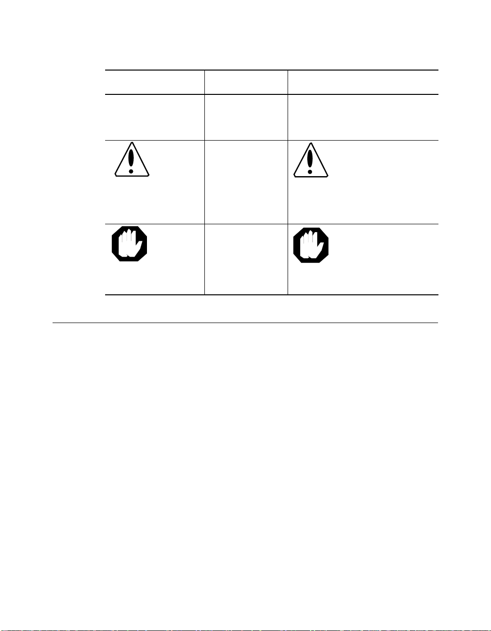
Convention Indicates Example
Note: A Note. The
Caution: A Caution. A
Warning: A Warning. A
Related Documents
This section provides infor mation on supporting documentation, including:
❑ 3Com Documents
information is
important
condition may
damage
software or
hardware
condition may
threaten
personal safety
Note: Use STP lobe
cables for your system.
Caution: Do not put
your installation
diskettes on a
magnetic surfac e.
This may damage the
diskettes.
Warning: Wear eye
protection when
performin g these
maintenance
procedures.
❑ Reference Documents
ONline Ethernet Bridge Module Installation and Operation Guide xix
Page 20

3Com Documents
The following documents provide additional i nformation on 3Com
products:
17-Slot ONlin e System Concen trator Ins tallatio n and O pera tion
Guide – Explains how to install, operate, and manage th e 3Com ONline
17-Slot System Concentrator (Models 5017C-LS and 5017C with load
sharing).
6-Slot ONline System Concentrator Installation and Operation
Guide – Explains ho w to install, operate, and manage the 3Com ONline
6-Slot System Concentrator.
ONline Ethernet Management Module Installation and Operation
Guide – Explains how to install, operate, and use the 3Com O Nline
Ethernet Managem ent Module.
ONline Management Commands Guide – Provides an alphabetized
reference resource describing all ON line management co m m ands.
For a complete list of 3Com documents, contact your 3Com representative.
Reference Documents
The following documents supply related background information:
Case, J., Fedor, M., Scoffstall, M., and J. Davin, The Simple Network
Management Protocol, R FC 1157, University of Tennessee at Knoxville,
Performance Systems International and the MIT Laboratory for Computer
Science, May 1990.
Rose, M., and K. McCloghrie, Structure and Identification of
Management Information for TCP/IP-based Internets, RFC 1155,
Performance Systems International and Hughes LAN Systems, May 1990.
xx ONline Ethernet Bridge Module Installation and Op eration Guide
Page 21

Introduction
1
This chapter describes the ON line™ Ethernet Bridge Mo du le basic
capabilities, operation, and system configuration alternatives. The ONline
Ethernet Bridge Module is referenced throughout this manual as the Bridge
Module.
The Bridge Module
The Bridge Module is a high-performance bridge that transparently
interconnects your facility-wide Ethernet and IEEE 802.3 networks to form a
single extended LAN. The Bridge Module fits into your O Nline System
Concentrator unit using only two slots and allo ws you to perform the
following functions:
❑ Interconnect Ethernet and IEEE 802.3 subnetworks
❑ Isolate local traffic on subnetworks through dynamic and permanent
packet filtering
❑ Configure redundant LAN interconnection by using the IEEE 802.1(d)
Spanning Tree Protoc ol
Introduction 1 - 1
Page 22

❑ Monitor your extended LAN using network management features
including:
– Traffic counters
– Diagnostic information
– Address Table information
Bridge Modu le Featu res
The following section describes the major features of the Bridge Module.
These features include:
❑ Interoperability
❑ Spannin g Tree Loop Control
❑ Traffic Localization
❑ Automatic Address Learning
❑ High Performance Design
❑ Transparent Operation
❑ Downloadable Firmware
❑ Network Management Capabilities
❑ Media Configuration Opt ions
❑ Diagnostics and Self-T est
Interoperability
The Bridge Module provides one external 15-pin transceiver cable connector
for hookup to an Ethernet and/or IEEE 802.3 subnetwork. If you do not
make this external connection, b oth the incoming and outgoing
connections are made over the backplane.
1 - 2 ONline Ethernet Bridge Module Installation and Operation Guide
Page 23

Depending upon the type of bridg e connection you select (backplane or
the AUI connection), an individual port can connect to any of the following
devices:
– ONline System Concentrator
– Ethernet transceivers
– Ethernet repeaters
– Other data-link bridges
ONline System Concentrator
Y ou can connect to another concentrator through the AUI port or through
another modu l e that is on the same channel as the Bridge Module. For
example, you can use an ONline Fiber Module on the same channel as the
bridge backplane connection to interconnect 10BASE-FB Stars, ONline
System Concentrators, LAN-TO-LAN Hubs, 10BASE-FB/PC Adapter Cards, or
10BASE-FB Transceiver s.
Ethernet Transceivers
You can use the Bridge Module to interconnect Ethermodem Broadband
Ethernet LANs with the ONline System Concentrator. The Bridge Module
front panel AUI port connects to a male AUI port on the Ethermodem
transceiver. It can also be con nected to the following transceivers:
– A transceiver multiplexer such as DEC's DELNI™
– A transceiver on a standard Ethernet coaxial cable
– A transceiver on a thin coaxial or twisted pair cable
– An Ethermodem broadband transceiver
Ethernet Repeaters
You can use the Bridg e Module to interconnec t Ethernet/IEEE 802.3
subnetworks that contain repe aters. The bridge acts as a node on each
subnetwork to which it is attached, and therefore does not affect the
maximum distance or repeater limitations.
Introduction 1 - 3
Page 24

Other Bridges
The Bridge Module can operate on an expanded LAN that contains other
bridges under the following two conditions:
1. The other bridges must forward packets transparently at the data link
layer .
2. The total end-to-end delay in the extended network must not exceed
the time-out requirements of higher level protocols. 3Com does not
recommend configuring the Bridge Module on networks wi th more
than seven (7) bridge hops between any two nodes .
Y ou can connect the Bridge Module to any of the above devices in various
combination s and configurations. Refer to th e section in this c hapter,
Media Configuration Options, for configuration examp l es and diagrams.
Note: The Bridge Module is not compatible with Ethernet Version
1 transceivers or cables.
Spanning Tree Loop Control
The Spanning T ree Algorithm and Protocol (ST AP) is used among bridges in
a LAN to ensure only single paths exist between stations. The Spanning
Tree protocol is needed when there are parallel bridges forming a loop
between Ethernet LANs on the network. This type of network also provides
redundancy throughout the network so tha t if the primary bridge fails, a
backup bridge will take over within 1 0 to 20 seconds.
If there are multiple Bridge Modules or Midnight Bridges between LANs on
the network, the Spanning Tree protocol ensures that only one bridge
enters the data sending (or forwarding) state. This bridge is called the
Designated bridge. Other bridges remain in the blocking state until needed.
While in the blocking state the bridge does not forward packets, but it does
continue to monitor and part icipate in the Spanning Tree protocol. If the
designated bridge fails for any reason, the blocked bridge will learn of the
failure through the Spanning Tree protocol and enter the forwarding state.
1 - 4 ONline Ethernet Bridge Module Installation and Operation Guide
Page 25

More information about the Spanning Tree protocol is inclu ded in
Appendix B.
Traffic Localization
The Bridge Module is a packet store-and-forward device that receives all
packets and, if necessary , forwards them from the subnetwork on one side
of the bridge to the subnetwork on the other side. The Bridge Module also
acts as a packet filter, filtering packets based upon local destination
addresses.
Filtering can isolate high traffic subnetworks fro m the rest of the LAN. For
example, if the systems and servers in a cluster or subnetwork usually
communicate with each other and rarely communicate with systems on
other LANs, the Bridge Mod ule does not forward that traffic to the
extended LAN, except a s needed.
The Bridge Module allo ws you to set up to 100 dev ice addresses to be
always forwarded to or never forwarded to. This can be used to keep
sensitive subnetwor k traffic local at all tim es. Enhanced network
performance is also gained through the use of this feature.
Topology Switching
T opology switching enables you to automatically change the extended LAN
topology without having to recable or take the network down. Bridging
functionality lets you switch between any two ONline channels or between
any ONline channel and an external Ethernet network. T opology switching
is performed using the Bridge Module's command interface. The Bridge
Module automatically recalculates the Spanning T ree to reorient the bridge
in the network.
Automatic Address Learning
When attached to a subnetwork, the Bridge Module dynamically learns the
addresses of all nodes on the subnetwork - th us it is called a learning
Introduction 1 - 5
Page 26

bridge. The Bridge looks at the source address of each packet generated on
the subnetwork and creates a database containing these addresses.
Note: If a node does not generate any packets, its loc ation
cannot be dynamically learned by the Bridge Module.
When a packet is received by the Bridge Module, its destination address is
compared with the addresses in the source subnetwork database. T able 1-1
describes what happens when a packet is received by the Bridge Module.
Table 1-1. Packet Distribution by Bridge Module
The Destination Address is.. The Packet is...
Found in the source
subnetwork databa se
Not found i n the source
subnetwork databa se
High-Performance Desig n
While address filtering can reduce traffic loads on y our network, it is
important to overall network integrity for a learning bridge to run as fast as
the network. The Bridge Module ensures high performance in the following
ways:
1. It uses high-speed multi-port memory so the IEEE 802.3 controllers
and the CPU all have separate access to the common packet memory .
Once a packet is received into this memory, it does not have to be
copied to be forwarded.
Considered to be local to th a t
subnetwork (its source and destination
are on the same subnetwork). The
Bridge Module does not for ward the
packet.
Considered to be on a different
subnetwork and forwarded onto the
other subnet work (or the destination
node has not generated any traffic).
1 - 6 ONline Ethernet Bridge Module Installation and Operation Guide
Page 27
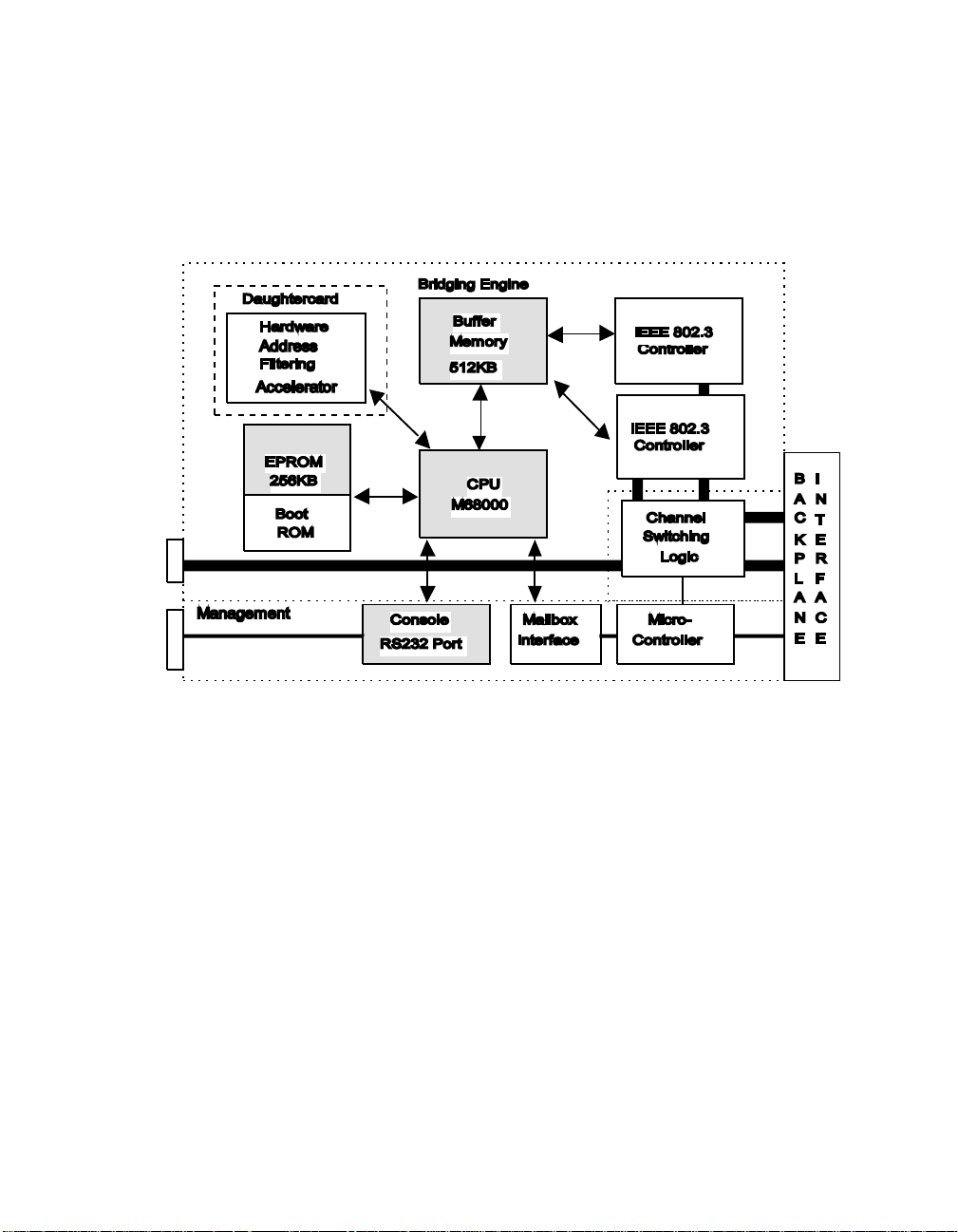
2. It uses dedicated hardware to accelerate th e address filtering
operation to ensure the highest possible performance in an 802.3 to
802.3 bridge (Figure 1-1).
Figure 1-1. Bridge Module Hardware Design
Transparent Operation
The ONline Ethernet Bridge Module operates transparently to other
stations on the LAN, therefore no special software is required on any
other station. This means an extended LAN using Ethernet Bridge
Modules can support any protoco l that runs over IEEE 802.3 LANs, such
as Sun Microsystems NFS, Novell Inc. NetWare, 3Com 3+, and other
products based on protocols such as XNS, TCP/IP, and ISO.
Introduction 1 - 7
Page 28

Downloadable Firmware
As firmware upgrades become available from 3Com, you can download
this new firm ware to your Bridge Module using an IBM-compatible PC
connected to the module's RS-232 serial port. Downlo adable firmware
ensures that you have access to new features as soon as possible - saving
the cost, time, and inconvenience of installing new PROM chip s. This
feature is explained in detail in Chapter 6, Firmware Download Instructions.
A 3Com Firmware Distribution Kit (Part number 5000-FDK) is necessary for
downloading the firmware to your Bridge Module. This kit contains the
appropriate RS-232 cable and software for performing future firmware
upgrades. The kit is ordered as a single copy per site, supporting multiple
Bridge Modules. The upgrades themselves are contained in another kit, the
Ethernet Bridge Update Distribution Kit (Part number 5102B-UDK-x.x).
The Ethernet Bridge U pdate Distribution Kit is available in two versions limited and unlimited. The limited version (5102B-UDKL-x.x) allows you to
upgrade only one Bridge Module. The unlimited version (5102B-UDKU-x.x)
enables you to upgrade an unlimited number o f Bridge Modules.
Network Management Capab ilitie s
You access the Bridge Mod ule management function s through an
out-of-band connection via the serial RS-232 port on the front panel. Y ou
can also access the module through an inband connection from an existing
Bridge Module, Midnight Bridge, or network management module. To
manage all other Bridge Modules and manageable devices in the extended
LAN via inband management, you must first log out of the current session
and then log in to another device. Refer to the REMOTE_LOGIN command
in Chapter 4 for details on accessing remote devices.
Connection through the RS-232 port means you can manage your Ethernet
Bridge Modules locally, from remote locations using modems and dial-up
telephone lines, and through LAN-based terminal servers.
1 - 8 ONline Ethernet Bridge Module Installation and Operation Guide
Page 29

This version of the Bridge Module software also provides SNMP (Simple
Network Management Protocol), which allows the bridge to be managed
from a SNMP-based network managem ent workstation.
The Bridge Module offers capabilities to help manage your extended LAN.
The primary categories of management functions are:
1. Bridge and N etwork Status Reporting
2. Network Statistic Collection and Repo rting
3. Bridge Address Filter Settings
The reporting and other network management options are described in
detail in Chapters 3 and 4.
Media Configura tion Options
The Bridge Module offers two connection alternatives:
❑ One AUI port connector (port 1) and one Backplane channel (port 2)
❑ Two Backplane ch annels (ports 1 and 2)
Message traffic flows between stations on LANs connected by the Bridge
Modules as if they were on one extended LAN. Since CSMA/CD (Carrier
Sense Multiple Access/Collision Detection) collision information does not
have to propagate between interconnected networks on an extended LAN,
you can configure each LAN up to the norma l maximum len gth and
number of stat ions.
A sample configuration is shown in Figure 1-2.
Introduction 1 - 9
Page 30
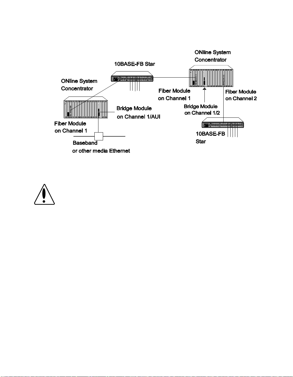
Figure 1-2. Sample Bridge Module Configuration
Caution: If your extended LAN includes protocol-specific routers,
make sure the total number of routers in the extended
LAN does not exceed the maximum allowed by the
protocol for a single LAN.
AUI and Backplane Connections
When the bridging connections are made through the AUI port on the
front of the Bridge Module and over the backplane, the distance between
two end-node devices can be:
❑ 8000 meters for baseband (4000 meters from the backplane
connection and 400 meters from the AU I connection)
❑ 8000 meters for broadband (4000 meters on each side of the bridge)
An example of a th ick-cable configuration is shown in Figure 1-3.
1 - 10 ONline Ethernet Bridge Module Installation and Operation Guide
Page 31
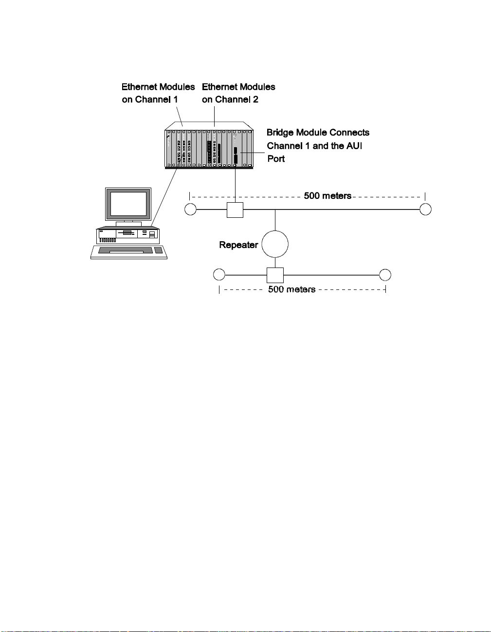
Figure 1-3. Backplane Channel Bridged to Broadband Segment
Backplane Connectio ns
When you bridge two channels using the backplane as both port 1 and
port 2, the maximum distance between two end-node devices can be 8000
meters (4000 m on each side of the bridge). This type of configuration is
shown in Figure 1-4.
Introduction 1 - 11
Page 32

Figure 1-4. Backplane Channels Bridged T ogether
Diagnostics and Self-Test
On power-up, the Bridge Module performs the following diagnostic tests:
❑ Bridge self-tests
❑ CRC check of code memory (Flash EPROM)
❑ Port loopback tests
These tests allow the Bridge Modu le to check its own circuitry and
communication interfaces to verify its ability to send and receive data. If the
bridge fails any of the diagnostics, the front panel LEDs indicate an error
code. Power- up self-test and error codes ar e described in Chapter 5 and in
Appendix D. You can also diagnose local and remote bridges using the
management commands. These commands allow you to view bridge and
network information that is helpful in diagnosing network and bridge
problems. Chapter 4 provides a complete description of each Bridge
Module com mand.
1 - 12 ONline Ethernet Bridge Module Installation and Operation Guide
Page 33

2
Installation
This chapter describes the precautionary, unpacking, and installation
procedures for the Bridge Module. It also provides illustrations of the
module and describes the front panel indicators, button, and connectors.
This chapter is divided in to the following sections:
❑ Precautionary Procedures
❑ Unpacking Procedures
❑ Summarized Bridge Installation Procedure
❑ Installation Procedures
❑ Confirming Bridge Operation
This chapter provides examples of the commands necessary to initially
configure the Bridge Module. In the examples, user input is indicated as
lower-case underlined text.
Precautionary Procedures
Electrostatic discharge (ESD) can damage static-sensitive devices on circuit
boards. F ollow these precaution s when you handle the Bridge Module.
Installation 2 - 1
Page 34

❑ Do not remove the board from its anti-static shielding bag until you
are ready to inspect it.
❑ Handle the board by the faceplate only.
Use proper grounding techniques when you install the Bridge Module.
These techniques include using a foot strap and grounded mat or wearing
a grounded static-discharge wrist strap. An alternate method is to touch a
grounded rack or other source of ground just before handling the module.
Unpacking Procedures
Use the following procedure when unpacking your Bridge Module.
1. Verify that the Bridge Module is the correct model by matching the
model number listed on the side of the shipping carton to the model
number you ordered (5102B-EE).
Note that the product model numb er printed on the shipping box
differs from the model number on the product. The model number
on the shipping box contains the prefix ‘3C9’.
2. Remove the module in its anti-static shielding bag from the shipping
carton.
3. Remove the module from the anti-static shielding bag and inspect it
for damage. Always handle the Bridge Module by the faceplate,
being careful not to touch the components.
If the module appears to be damaged, replace it in the anti-static
shielding bag, return it to the shipping carton and contact your local
supplier .
3Com suggests you keep the shipping carton and anti-static shielding bag
in which your module was shipped in case you later want to repackage the
module for storage or shipment. Record the serial number of your Bridge
Module and other information specific to your modules in the Slot Usage
Chart in Appendix B of the ONline System Concentrator Installation an d
Operation Guide.
2 - 2 ONline Ethernet Bridge Module Installation and Operation Guide
Page 35

Summarized Bridge Installation Procedure
The following list summarizes the procedure for installing and operating
the Bridge Module.
❑ Plug the Bridge Module into the ONline System Concentrator with
the loopback connector attached to the AUI port and verify internal
diagnostics.
❑ Once the Bridge Module passes diagnostics, pull it back out of the
concentrator and set the dip switches to the two channels you want
to bridge (or set these values through network management without
removing the module).
❑ Plug the module back in the concentrator and the Bridge Module
performs self-test diagnostics. Upon completion of the diagnostics,
the unit begins learning the addresses of nodes on either side by
monitoring network traffic.
❑ Connect an ANSI terminal to the RS-232 port on the module faceplate
to configure SNMP values and any op tional parameters.
❑ Monitor the extended LAN using the bridge management capabilities
through your connected terminal or via a modem or other interface
providing asynchronous serial communications.
Installation 2 - 3
Page 36

Module Front Panel
The front panel has eight indicators (LEDs), one button, two connectors,
and the module extractor. The front panel indicators inform you of the
operating state of your Bridge Module. Figure 2-1 shows the Bridge
Module front panel and Table 2-1 lists the function of each LED, button,
and connector on the module faceplate.
PORT 1
PORT 2
RX
TX
FWD
MGMT
TEST
RESET
Reset Button
AUI
RS-232
SERIAL
PORT
Female AUI Port
RS-232 Serial Port
Module Extractor
Figure 2-1. Bridge Module Front Panel
Refer to Appendix D for information on using and interpreting the Bridge
Module front panel controls and indicators.
Module Extractor
The module extractor is located at the bot tom of the module faceplate.
Use the module extractor to remove the module from the concen trator.
2 - 4 ONline Ethernet Bridge Module Installation and Operation Guide
Page 37

Just pull the extractor lever down to remove the module from the
concentrator.
Table 2-1. Bridge Module LEDs, Button, and Connectors
Label Function
RX Indicates receive activity on the IEEE 802.3 or Ethernet
network connected to that port.
TX Indicates transmit activity on the IEEE 802.3 or
Ethernet network connected to that port.
FWD Indicates that the bridge is in forwar ding state and is
sending packets from that port.
MGMT Indicates that administrator mode o f the bridge is
currently active.
TEST Indicates Bridge Module self-test activity.
RESET Press this button to reset the Bridge Module. Same as
issuing the RESET command or plugging in the
module.
AUI Female AUI connector for 15-pin transceiver
connection.
RS-232 SERIAL
PORT
RS-232 port for connecting terminal, terminal server ,
PC or modem for Management Interface.
Installation 2 - 5
Page 38

Dip Switches
The Bridge Module has one dip switch component with 4 switches, located
on the larger of the two boards on the module. The switches on this dip
switch enable you to set the channels that are to be bridged together.
Figure 2-2 shows the location and factory settings of the dip switch on the
module.
RX
TX
FWD
MGMT
TEST
RESET
AUI
RS-232
SERIAL
PORT
SW1
ON
OFF
On
On
Off On
Off
1 2 3
1
4
2 Channel
1
On
2
Off
AUI Port
Off
Isolated
PORT 1
3 4 Channel
On On
On
Off
Off
Default Settings
Off
On
Off
PORT 2
1
2
3
Isolated
Backplane DIN
Connectors
Figure 2-2. Bridge Module and Dip Switch Location
2 - 6 ONline Ethernet Bridge Module Installation and Operation Guide
Page 39

Channel-Select Switch Settings
All ONline media modules are equipped with the technology to work with
the ONline System Concentrator's unique T riChannel Architecture. This
architecture lets you assign the module to any of three channels on the
ONline System Concentrator backplane. Refer to Chapter 1 in the ONline
System Concentrator Installation and Operation Guide for a complete
discussion of ONline's TriChannel Architecture.
The channel-select switches on the Bridge Module enable you to assign the
module to bridge any two backplane channels, or to bridge one backplane
channel to the AUI port on the front of the module. Both channels must
be running Ethernet/IEEE 802.3.
Switch 1 is factory-set to th e Off position and switch es 2, 3, and 4 are
factory-set to the On position. Therefore, the Bridge Module is initially
configured to bridge the AUI port on the front of the module to backplane
channel 1. The default settings are highlighted in the Table 2-2. To
configure the module to bridge different channels, refer to the information
in Tab l e 2-2.
Table 2-2. Channel Select Dip Switch Settings
Port 1 Switch 1 Switch 2 Port 2 Switch 3 Switch 4
Channel 1 On On Channel 1 On On
Channel 2 On Off Channel 2 On Off
AUI Port Off O n Channel 3 Off On
Isolated Off Off Isolated Off Off
If you have an ONline network management mod ule installed in your
concentrator , you can remotely override these switch settings. Refer to the
appropriate ONline Management Module Installation and Operation Guide
for informatio n on remotely managing the ports.
Installation 2 - 7
Page 40

Related Features
The following sections describe functions that allow you to:
❑ check the module's channel assignment and LED functionality
❑ remotely manage th e Bridge Module from anoth er device
LED and Channel Verification
The ONline Controller Module is equipped with an LED check but ton on the
front panel. The LED check button has two functions: it causes all LEDs in
all modules in the con centrator to light, and it causes each module to
identify the channel to which it is assigned. When you press this button,
the module initiates a test to all modules in the concentrator . Any LED that
does not light is defective.
After the five seconds elapse, the diagnostic continu es with a channel
check of all modules. Each Port Status LEDs should respond by blinking the
number of times to correspond with the channel to which it is assigned.
The channel check sequence repeats five times. Table 2-3 explains the
channel check codes.
Table 2-3. Channel Check Codes
Port 1
LEDs
1 Blink Port is configured for
2 Blinks Port is configured for
4 Blinks Port is configured to
Off Port is isolated Off Port is isolated
2 - 8 ONline Ethernet Bridge Module Installation and Operation Guide
Port 1 Configuration
channel 1
channel 2
the AUI connec tor
Port 2
LEDs
1 Blink Port is configured for
2 Blinks Port is configured for
3 Blinks Port is configured for
Port 2 Configuration
channel 1
channel 2
channel 3
Page 41

Remote Network Management
The ONline Ethernet Management Module (EMM) and ONline T oken Ring
Management Mo dule (TRMM) provide remote networ k ma nagement
capabilities for the ONline System Concentrator and its modules. These
management modules also have the ability to override the channel-select
dip switches on the Bridge Module. Refer to th e appropriate ONline
Management Module Installation and Operation Guide fo r additional
information on network management features.
You can also log into the Bridge Mo dule from a network management
module, from another Bridge Module, or from a Midnight Bridge. This type
of connection is called inband management. Once logged into this module
you are able to make changes and show statistics as if you were locally
connected to the module.
Installatio n Procedures
Y ou do not need to power down the ONline System Concentrator to install
the Bridge Mo dule. You can insert the module w hile the concentrator is
operating (this is called a hot insertion). The installation procedure is
divided into the following steps:
❑ Pre-installation test
❑ Connecting a terminal
❑ Connecting the transceiver cable
❑ Selecting bridge and channel settings
Installation 2 - 9
Page 42

Pre-Installation Test
When you install th e Bridge Module into the concentrato r, the unit
performs a self-test to verify proper operation of the internal hardware and
communicatio n interfaces. To test the un it independently of network
activity, follow these steps prior to plugging the module into the
concentrator :
1. Install the provided Ethernet loopback connector to the AUI port on
the module as shown in Figure 2-3.
Figure 2-3. Connecting Loopback Connector
2. Remove two adjacent blank concentrator panels to expose two slots
for the Brid ge Module.
3. Insert the module into the board guides at the top and bottom of the
slots and slide it into the concentrator . Make sure the connectors are
well seated into the backplane of the concentrator.
2 - 10 ONline Ethernet Bridge Module Installation and Operation Guide
Page 43

Figure 2-4 shows the installation of the Bridge Module.
Figure 2-4. Installing the Bridge Module
4. Fasten the three spring-loaded screws on the front of the Bridge
Module faceplate to the concentrator with your fingers to provide
ground - do not overtighten.
As the Bridge Module performs its internal diagnostics, the T est LED on the
front panel remains lit. Various LED combinations appear during the
self-test. If the power- up self-test is successful, the Test LED goes off after
approximately 20 seconds and the module returns to the configuration set
up by the dip swi tches and the TX LED w ill blink.
If none of the module faceplate LEDs light or if the Test LED blinks, refer to
Table 2-4 for appropriate action.
Installation 2 - 11
Page 44

Note: The loopback connector must be attached to the AUI port
or the self-test will not function properly.
Table 2-4. Power-Up Problem Resolution
Problem Possible Solutions
All indicators are off Verify that the concentrator is receiving
power.
Press the LED/Channel Check button on the
ONline Controller Module to check if the
LEDs light.
Pull the Bridge Module out using the
module extractor and re-insert it into the
concentrator.
The Test LED is blin king Your unit failed the power-up self-test.
Write down the LED blink sequence
displayed on the front panel and refer to
Appendix D to identify the error code.
If you cannot correct the error at your site,
contact 3Com Customer Support as
explained in Append ix E.
If these alternatives fail to f ix the problem, your un it is mal functioning.
Repack it in the shipping carton and contact your 3Com representative for
corrective action.
5. Once the self-test is successful, remove the loopback connector and
continue with the installation procedure.
2 - 12 ONline Ethernet Bridge Module Installation and Operation Guide
Page 45

Connecting a Terminal
You access Bridge Module management through the management
interface - the RS-232 port on the front of the module. Y o u can connect
any device that presents an ASCII asyn chronous interface, including
terminals, PCs capable of terminal emulation, and modems.
Note: If the concentrator has an installed network management
module, you can use the REMOTE_ LOGIN command to link
to the Bridge Module to per form brid ge management.
Refer to the appropriate ONline Management Module
Installation and Operation Guide for information on remote
management.
For proper operation you need to make sure the terminal and Bridge
Module are communicating at the same baud rate before connecting
them. The Bridge Module has been factory-set to 9600 baud. Y ou must
initially configure your terminal to a 9600 baud rate so it can communicate
with the module. Consult your terminal's user guide for instructions on
how to set its baud rate. In addition, you must configure the terminal's
parity, number of data bits, and stop bi t s to the Bridge Modu l e factory
defaults as shown in Table 2-5.
Table 2-5. Bridge Module Default Terminal Settings
Parameter Factory Setting
Baud 9600
Data_bits 8
Parity None
Stop_bits 2
Flow Cont rol XON/X OFF
Installation 2 - 13
Page 46

Once you have configured your terminal to match the factory defaults of
the Bridge Mo dule, you can connect a cable from the terminal to the
RS-232 port on the Bridge M odule.
Connecting to the Bridge Module RS-232 Port
The RS-232 cable connects to the management interface on the Bridge
Module front panel. T able 2-6 defines general cabling guidelines that apply
for connecting various devices to the management interface..
Table 2-6. RS-232 Cable Guidelines
Device Cable
Terminal Female-to-fema le crossover
Female-to-male crossover
Modem Male-to-female straight-through
Terminal Server Refer to Supplier Documentation
Note: The 3Com Firmware Distribution Kit (5000-FDK) provides a
cable for connec tion to a PC or terminal.
Appendix C describes the proper pinouts for male-to-female, crossover
RS-232 cable.
Connecting the Transceiver Cable
This section explains how to connect the transceiver cable to the AUI port
on the Bridge Module. If you do not intend to use the AUI port to connect
to a subnetwork, skip this section.
To install the transceiver cable, follow these steps while referrin g to
Figure 2 -5:
1. Push the slide latch to t he up position.
2 - 14 ONline Ethernet Bridge Module Installation and Operation Guide
Page 47

2. Plug the transceiv er cable into the jack.
3. Firmly push the slide latch down until it snaps into the locking
position.
4. Gently p ull on the connector to make sure the latch is secure.
3Com recommends strain relief for this cable to avoid placing undue stress
on the connec tor.
AUI
RS-232
SERIAL
Figure 2-5. Connecting Transceiver Cable
Setting Bridge and Chann el Para meter s
Before selecting the channels that the module will bridge, verify that the
transceiver cable connection (if used) is secure at both ends of the cable
and that the transceiver is on a valid terminated segment. Then, follow the
steps below to complete the in stallation.
1. If you plan to manage the Bridge Module through an SNMP
workstation, you must set the following SNMP values : IP address,
Community Table, Default Gateway, Subnetwork Mask, and Alert
settings.
Installation 2 - 15
Page 48

2. Set the addr ess filtering attributes (hard-coded addresses that ar e not
to be forwarded to, or that should always be forwarded to) using the
SET FILTER com mand. At this time you shou ld also set any other
bridge settings that need to be changed before actually setting the
channels to bridge, such as Spanning Tree parameters.
3. The default setting is for the Bridge Module to configure the channels
from the dip switch settings at startup and when rebooted. If y ou set
the channels through management (through a network management
module or from Bridge Module Management) you need to issue the
command as shown below to ensure that in the fu ture, the Bridge
Module configures from the values in memo ry:
OEBM> set bridge dip_configurat ion disable [ENT ER ]
OEBM> save bridg e [ENTER ]
4. Select the channels th at t he module will bri dge using one of the
three procedures explained below.
a. Using a terminal attached to the Bridge Module, issue the SET
BRIDGE CHANNEL command. For example, the commands SET
BRIDGE CHANNEL PORT1 1 and SET BRIDGE CHANNEL PORT2 2
will bridge channels 1 and 2 on the concentrator backplane.
Refer to Chapter 4 for a complete description of the SET BRIDGE
CHANNEL command.
b. Using a terminal attached to a network m anagement module,
issue the SET PORT NETWO RK command. For example, the
command belo w sets port 1 of a Bridge Module in slot 5 to
backplane network 1. Refer to the appropriate ONl ine
Management Module Installation and Operation Guide for a
complete description of the S ET PORT NETWORK command.
EMM> set port 5.1 network ethernet_1 [ENTER]
2 - 16 ONline Ethernet Bridge Module Installation and Operation Guide
Page 49

c. If you do not have a terminal connected to either the Bridge
Module or to a management module, slide the module out from
the concentrator (using the module extractor) and manually set
the dip switches on the board to bridge two channels. Refer to
T able 2-2 and Figure 2-2 in this chapter for an explanation of the
dip switch settings.
5. Verify that the bridge is working properly by viewing the TX and RX
LEDs. If there is traffic on the subnetworks, the transmit and receive
LEDs on the front panel will be blinking. If there appears to be a
problem, refer to Chapter 5, Troubleshooting.
Figure 2-6 shows an installed Bridge Module.
Bridge Module
Figure 2-6. Installed Bridge Module
Installation 2 - 17
Page 50

Confirming Bridge Operation
Y o u confirm operation of the Bridge Module by sending packets between
two Ethernet or two IEEE 802.3 nodes on separate subnetworks. Here are
some suggested ways of doing this dep en ding on your application:
❑ If your application uses MS-DOS networking software such as Digital
Equipment's DECnet™-DOS or PCSA, Novell's NetWare, or 3Com's 3+,
simply issue a DOS command when logged into your server directory.
❑ If your application accesses UNIX host computers using the TCP/IP
protocol, attempt to establish a terminal connection using the T elnet
protocol, or to transfer a file using th e FTP protocol.
❑ If your application accesses DEC VAX™ hosts using LAT, attempt to
establish a terminal con nection.
❑ Issue the PING diagnostic command t o verify whether the Bridge
Module is active .
Follow the steps listed above to send packets across the Bridge Module and
watch the front panel indicators to verify the packets are being transmitted
and received.
2 - 18 ONline Ethernet Bridge Module Installation and Operation Guide
Page 51

3
Management Functions
This chapter shows you how to get started once you have installed the
Bridge Module in your concentrator and also explains the management
capabilities of the Bridg e M od ule.
You can use Bridg e Management to:
❑ modify the configuration of your Bridge Module to suit your specific
application
❑ customize filtering attrib utes
❑ display information about the network and local or remote b ridge
status
❑ display packet count er s and network errors
❑ download new firmware to your Bridge Module (Chapter 6)
Management Functions 3 - 1
Page 52

Using Bridge Man age men t
This section explains how to access Bridge Management, enter an d edit
commands, get help, view, modify, and save parameters. This section also
describes how to display status information about your network and your
Bridge Module.
Note: Bridging so ftware enables you to execute M an agement
commands regardless of bridgin g activity. Therefore,
bridging performance will be affected for the duration of
the command execution.
Connecting to the Management Interface
Refer to the section titled “Connecting a Terminal” in Chapter 2 for
instructions on connecting your terminal to the Management Interf ace
(RS-232 port ).
Entering and Editing Commands
You manage the Bridge Module by entering comm ands at the
management prompt. The default management prompt is “OEBM>," but
can be customized. Use the keys described in Table 3-1 when entering
commands on the command line.
Caution: If the management prompt appears as “>>," it means
that the current Flash EPROM is faulty and that the
system is runnin g off the Boot PROM (a subset of the
operational code). Type the HELP comman d for
information on the V1.3 command set. This command
set will keep your bridge operational, but with reduced
capabilities.
Contact 3Com Customer Support as outlined in Appendix E.
3 - 2 ONline Ethernet Bridge Module Installation and Operation Guide
Page 53

Table 3-1. Command Line Key Functions
Key Function
[BS] or
[Backspace]
Moves the cursor back one character and deletes
that character.
[DEL] or [Delete] Same as Backspace.
[ENTER] Enters the command.
[SPACE] Completes a com m and through command
completion.
[CTRL-C] Returns to a blank command line (management
prompt) at any time.
[CTRL-R] Retypes the previous command string on the
command line.
? Displays the available commands or command
options.
Command Com p letion
Bridge Management accepts abbreviated com m a nd input throug h a
feature called Command Completion. With Comm and Comp letion you
need only type the minimum number of letters required to distinguish the
command or argument from other acceptable choices and press the SP ACE
bar to complete the com m and. An example of command comp letion is
shown below:
OEBM> sa [SPACE]
After you press [SPACE], the command is completed as follows:
OEBM> save
If the letters you enter are not sufficient to determine a unique command,
Bridge Management waits for you to enter more characters. For example,
Management Functions 3 - 3
Page 54

entering the letter S followed by [SPACE] is not sufficient for Bridge
Management to determine which command you are issuing because there
are three commands that start with S - SAVE , SET, and SHOW.
Getting Help
The HELP command displays a screen of general information on using
Bridge Managem ent. For example, type help at the command line, press
[ENTER], and the following screen of help information displays.
OEBM> help [ENTER]
Usage: help {command}
{command} :: Chipcom |
clear *|
help |
logout |
maintain *|
monitor |
ping |
remote_login |
reset *|
revert *|
save *|
set *|
show |
Help provides useful information to remind a knowledgeable
user of the meaning of commands. The commands with an
asterisk are administrator commands only.
If you press [ENTER] when an argument is expected, Bridge Management
prompts for additional information. You can type a question mark (?) in
response to any prompt to list acceptable command s, arguments, or
parameter values.
The Bridge Module management interface provides you with co mmands
that enable you to examine, modify, and save param eters. These
commands and their use are described next.
3 - 4 ONline Ethernet Bridge Module Installation and Operation Guide
Page 55

Examining Parameters
The SHOW command lists the current value of any parameter you specify .
For example, the SHOW SP ANTREE command displays the current spanning
tree parameters, as show n below.
OEBM> show spantree [ENTER]
Spanning Tree Parameters:
Mode Enabled
Bridge Priority 0
Path Cost Port 1 10
Path Cost Port 2 10
Hello Time (sec) 2
Forward Delay Time (sec) 15
Listen Time (sec) 20
Spantree Hello Address: 01-80-C2-00-00-00
The SHOW DEVICE command displays the current device parameters and
values for the Bridge Module.
OEBM> show device [ENTER]
ONline Ethernet Bridge Module (OEBM); SNMP Management
Name: OEBM
Boot EPROM Version: v1.3 Serial Number: 330658 Restarts: 7
Flash EPROM Version: v2.0 Service Date: / /
Location:
3rd Floor Engineering
Port 1 Port 2
MAC Address: 08-00-8F-10-17-48 08-00-8F-10-17-49
IP address 127.0.0.1 127.0.0.1
Subnet Mask FF.FF.FF.00 FF.FF.FF.00
Default Gateway 0.0.0.0 0.0.0.0
For assistance contact:
Network Administrator
Diagnostics: ENABLED
SQE Mode: NORMAL
Management Functions 3 - 5
Page 56

Modifying Parameters
Parameter values are stored in non-volatile memory on the Bridge Module.
Your Bridge Module unit is shipped from the factory with specific default
parameter values. Some of the default parameter settings are shown on
the previous page in the example explaining the SHOW DEVICE command.
Use the SET command to modify parameter values. Y ou must first type the
administrator password when you log in to the management interface. The
administrator password provides access to commands that allo w you to
modify the cur rent bridge configuration.
Once you have entered the administrator password, you can change
parameter values using the SET command. Listed below is an example of
changing the Bridge Module terminal baud rate.
OEBM> set terminal baud 1200 [ENTER]
Terminal parameter changed
Once you have made all the parameter changes you want, you may want
to issue the SAVE ALL command and then logout of administrator mode to
prevent any unauthorized changes.
Saving Parame ter s
When you reboot the system, all paramet ers that can be set are reset to
their saved values. Therefore, to save the new parameter values you
changed and make them effective on the next reboot, you must issue the
SAVE co mman d befo re rebooting. Use the SAVE command to save
parameter values for the following groups:
❑ All
❑ Alert
❑ Bridge
❑ Community
❑ Device
3 - 6 ONline Ethernet Bridge Module Installation and Operation Guide
Page 57

❑ Filter
❑ Spantree
❑ Terminal
When you make configuration changes using the SET command, these
changes are effective immediately but are not saved permanently. You
must issue the SAVE command to keep the new configuration values. Only
saved values are in effect upon reset of the module or co ncentrator.
Note: If a power failure occurs within the concentrator, all
unsaved parameter values are lost.
Getting Started
This section briefly describes the steps to f ollow once the Brid ge Module
has been installed in the ONline System Concentrator and a terminal has
been attached to its RS-232 port. Table 3-2 outlines these steps. The
following section, Bridge Management Parameter Overview, describes each
step in detail.
Table 3-2. Procedures for Getting Started
Procedure Command Priority
1. Configure your
terminal to default
Bridge Module
communication
settings
2. Configure the Bridge
Module
❑ Set administrator
password
Refer to your terminal
vendor's docum entation
SET DEVICE PASSWORD
ADMINISTRATOR
Management Functions 3 - 7
Mandatory
Mandatory
Page 58

Table 3-2. Procedures for Getting Started (Continued)
Procedure Command Priority
❑ Set user passwords SET DEVICE P ASSWORD
USER
❑ Set the Bridge
Module:
Name, Management
Prompt, Location
SET DEVICE NAME
SET TERMINAL PROMPT
SET DEVICE LO CATION
SET DEVICE CONTACT
Contact information
❑ Set Terminal Timeout
SET TERMINAL TIMEOUT Recommended
value
3. Configure Bridge
Module SNMP values:
❑ Set the Bridge Module:
IP Address,
Community Table,
Default Gateway,
Subnetwork M a s k,
and Alert Settings
SET DEVICE IP_ ADDRESS
SET COMM UNITY
SET DEVICE
DEFAULT_GATEWAY
SET DEVICE
SUBNET_MASK
SET ALER T
4. Configure Spanni ng
SET SPANTREE... Recommended
Tree Parameters
Reco mmended
Recommended
Mandatory if
you plan to
manage via
SNMP or use
the PING
command
5. Save all configuration
SAVE ALL Mandatory
values you set
3 - 8 ONline Ethernet Bridge Module Installation and Operation Guide
Page 59

Bridge Management Parameter Overview
Bridge Management parameters fall into five general categories:
❑ Management Interface
❑ Remote Management
❑ Bridge Module Operation and Perform ance (Configuration)
❑ Filtering
❑ Statistics
The categories and specific parameters are discussed in the following
sections. All commands, arguments, and parameters are listed with
examples in Chapter 4.
Management Interface Parameters
The following three par ameters control the configuration of the Bridge
Management Interface:
❑ Te rminal Settings
❑ Prompt
❑ Password
Note that the new parameters you set are effective immediately; however ,
you must use the SAVE command for the new parameters to remain
effective after a system reboot. Remember that y ou m ust first use the
administrator password to enable use of the SET command.
Configuring the Terminal
You must initially configure your terminal to the same parameter settings
as the Bridge Module so the termi nal and the bridge can communicate.
Management Functions 3 - 9
Page 60

These parameters settings include the terminal's baud rate, data bits, parity,
and stop bits. For example, the BAUD parameter determines the baud rate
at which the RS-232 Bridge Management interface receives and transmits
data.
Note: If you need to set the mod ule baud rate to a rate slower
than 9600 baud, use a terminal set to 9600 baud to first
change the value. Once you change the baud rate for the
module, the terminal loses the connection to the bridge
because it is now set to a different speed. You must reset
the terminal's baud rate to match the Bridge Module's new
baud rate and then press [ENTER] to regain access to the
module. Y ou may then use the SAVE TERMINAL command
to save the new baud rate.
Your terminal settings must match the bridge factor y default values as
shown in Table 3-3.
Table 3-3. Bridge Module Termi nal Parameter Options and Factory
Defaults
Parameter Options
Baud 300, 1200, 2400, 4800, 9600 9600
Data_bits 7 or 8 8
Parity odd, even, or none none
Stop_bits 1 or 2 2
3 - 10 ONline Ethernet Bridge Module Installation and Operation Guide
Factory
Default
Page 61

Once you have configured your terminal to match the factory defaults of
the Bridge Module, press [ENTER] and the following header and password
prompt are displayed:
copyright 1992 Chipcom Corporation
ONline Bridge Module (v2.x)
Press [ENTER] and the Password prompt is displayed.
Password: [ENTER]
Initially the default password is a null string. You must enter a pas sword
within 10 seconds of receiving the Password: prompt or the terminal will
display “Password timed out”. If this happens, just press [ENTER] to receive
the password prompt again. By pressing [ENTER] at the Password pr ompt,
the following greeting and the management prompt is displayed.
Welcome to system administrator services on ONline.
OEBM>
You are now logged in as the administrator with full access to all
commands.
Setting Bridge Module Terminal Options (Optional)
This section is optional and is only used if you need to co nnect another
device to an Bridge Module that runs at a slower baud rate or different
parity or data bits values than the factory settings. For example, if you plan
on connecting a 4800 baud modem to an Bridge Module so that you can
remotely manage the concentrator , you need to change the Bridge Module
factory default baud rate from 9600 to 4800.
Enter the following command to change the baud rate to 4800:
OEBM> set terminal baud 4800 [ENTER]
Once you change the baud rate (or parity or data bits values), you lose your
connection to the terminal immediately. Therefore, you must change the
corresponding value on the terminal and then press the [ENTER] key to
return to the OEBM> prompt and then SAVE the terminal settings.
Management Functions 3 - 11
Page 62

Note: Terminal values you set using th e SE T comma nd are not
saved permanently until you issue the SAVE TERMINAL
command. Once the values are saved, if you log out or
even if the power fails, the saved value s are retained.
Automatic Modem Hangup
If you use a modem to connect to the Bridge Module, you may want to use
the SET TERMINAL HANGUP command to hang up the modem connection
automatically when you log out of the Bridge Module. The factory default
is disable, which does not auto matically hang up a modem. The following
example shows the command used to automatically hang up the modem
once you log o ut of the Bridge Module.
OEBM> set terminal hangup enable [ENTE R]
Note: If you fail to hang u p the modem connection, an
unauthorized user m ay pick up the last login session.
Configurin g t he Bridge M od ule
Now that the terminal settings are complete, you can configure the Bridge
Module in the c oncentrator. We recomm e nd that you com plete the
following steps when you log in for the first tim e:
1. Establish passwords
2. Configure other Bridge Module par am eters
3. Set Bridge Module SNMP value s
Establishing Passwords
Bridge Management provides a password-protection capability that allows
you to control access to certain commands and information. Y ou must be
in administrator mode to be able to change passwords. Note that when
you first log in the default password is [ENTER]. This default password will
provide you with administrator privileges.
3 - 12 ONline Ethernet Bridge Module Installation and Operation Guide
Page 63

Use the SET DEVICE command to modify passwords. Both the
administrator and the user passwo rds can con tain up to 15 characters.
Alphanumeric and special characters are allowed, including [DEL] and [BS].
The Bridge Module has two levels of password control:
1. Administrator Password - the administrator password provides access
to all Bridge Module com m ands, enabling both read and write
configuration access.
2. User Password - the user password provides limited access to Bridge
Module commands, enabling read access only.
Typing the HELP command will list the bridge command set with
administrator commands designated by an asterisk (*) as shown earlier in
this chapter.
Note: For security, the characters you enter in both the old and
new password fields are not displayed o n the screen.
The new passwords you set are in effect immediately , but you must use the
SAVE DEVICE (or SAVE ALL) command to save the new passwords
permanently.
Establishing the Administrator Password
Use the SET DEVICE PASSWORD AD MIN ISTRATOR command at the
management prompt to establish the administrator passw ord.
OEBM> set device password administrator [ENTER]
Enter current administrator password: <current password> [ENTER]
New password: <new password> [ENTER]
Verify: <new password> [ENTER]
Administrator password changed.
Management Functions 3 - 13
Page 64

Establishing the User Password
Use the SET DEVICE PASSWORD USER co mmand at the management
prompt to establish a user password. Note that you must be logged in as
the administrat or to change the user password.
OEBM> set device password user [ENTER]
Enter current administrator password: <current password> [ENTER]
New password: <new user password> [ENTER]
Verify: <new user password> [ENTER]
User password changed.
Configuring Other Bridge Module Parameters
The Bridge Module is factory set to certain default values that you may
need to change before using the Bridge Modu l e, for example the Brid ge
Module management prompt. If you are logged in as the administrator,
you can use the SET command to change or add the following Bridge
Module information:
❑ Bridge Module name (alias)
❑ Management prompt
❑ Contact name and location
❑ Terminal timeout value
❑ Concentrator Reboot Values
A full explanation of these values and how you set them is discussed in
Chapter 4 under the applicable SET command.
3 - 14 ONline Ethernet Bridge Module Installation and Operation Guide
Page 65

Bridge Module Name (Alias)
To make communication with your remote Bridg e Module s easier, we
recommend that you assign a unique name to each Bridge Module. You
can then use this name (instead of the IP address or Ethernet MAC address)
to reference the appropriate Bridge Module. In this man ner you can log
into a remote Bridge Module by issuing the REMOTE_LOGIN NAME <Bridge
Module Name> command. Use the SET DEVICE NAME command to assign
a unique name to your Bridge Module.
Bridge Module Management Prompt
You can customize the management prompt to a string of up to 15
characters long. The default management prompt is the string “OEBM> ”.
A new prompt could also in clude the angle bracket (>) and the trailing
space if desired.
Modify the management prompt by using the SET TERMINAL PROMPT
command as shown below.
OEBM> set terminal prompt Bridge_A> [ENTER]
Bridge_A>
3Com recommends that you set a unique management prompt for each
Bridge Module in the network. Doing so helps identify the specific Bridge
Module to which you are connected during remote management functions.
Refer to the REMOTE_LOG IN and LOGOUT command s and the Remote
Management section in this chapter for more information on remote
management.
Note: 3Com recommends that y ou set the prompt to the same
value as the Bridge Module name (alias).
Management Functions 3 - 15
Page 66

Contact Name and Location
You should enter the name of an appropriate service contact and the
concentrator location at this time to provide a handy reference should
there be a network problem. Use the SET DEVICE LOCATION and SET
DEVICE CONTACT commands to identify the location of the Bridge Module
and the name of the person responsible for the Br idge Module.
Terminal Timeout
You should set the terminal time out value to specify the amount of time
your terminal will remain logged in without any keyboard ac tivity. This
feature is useful for keeping unauthorized users off the system if you leave
your terminal without logging off. Once timeout has been set, the terminal
automatically logs you off the system if there is no keyboard activity for the
set period of time.
The default timeout value is 0, which means that no timeout has been set you will never be logged off automatically. Use the SE T TERMINAL
TIMEOUT command to set the timeout period in minutes.
Concentrator Reboot Values
When the Bridge Module is reset (or rebooted) using the factory d efault
settings, the module performs a full diagn ostic check and then sets all
parameters to the settings stored in its memory (except for channel
configuration if dip configuration is enabled). You have the option to
disable the diagnosti cs if you want the Bridge Module to boo t up faster.
You also have th e option to have the Bridge Module initialize its channel
configuration from memory (software settings) rather than its dip switch
settings.
Use the SET DEVICE DIAGNOSTICS DISAB LE com mand to bypa ss the
diagnostics and the SET DEVICE DIP_CONFIGURATION DISABLE command
to force initialization of the Bridge Module channel configuration from its
memory settings.
3 - 16 ONline Ethernet Bridge Module Installation and Operation Guide
Page 67

Setting SNMP Values
If you plan to manage the Bridge Module through an SNMP workstation
you must set the following attributes:
❑ IP Address
❑ Community Table
❑ Default Gateway
❑ Subnetwork Mask
❑ Alerts
IP Address
To manage via SNMP, every device on your network must have a unique IP
address. Use the SET DEVICE IP_ADDRESS command to assign unique IP
addresses to your Bridge Module ports. The following example shows the
command to assign an IP address to port 1 of the Bridge Module.
OEBM> set device ip_address_port1 195.24.25.36 [ENTER]
Community Table
The community table defines which SNMP stations on the network can
access and/or modify information from the Bridge Module, and which
station(s) will receive traps generated from the Bridge Module. Use the SET
COMMUNITY command to create a community table entry. For example,
the following command adds a community name of NCS with IP address
195.337.36.58 to have read_write access:
OEBM> set community NCS 195.337.36.58 read_write [ENTER]
You can use the SHOW COMMUNITY command to view the existing
community entries.
Management Functions 3 - 17
Page 68

Default Gateway
The default gateway is the IP address of the gateway that will receive and
forward packets whose addresses are unknown to the local network. The
default gateway is useful when sending Bridge Module alert packets to a
manager workstation that is on a different network. For example, the
following command specifies the gateway with the address 195.24.25.36
to be used as the default gateway for port 2 of the Bridge Module.
OEBM> set device default_gateway_port2 195.24.25.36 [ENTER]
Subn etwork Mask
The subnetwork mask is specific for each type of Internet class. In general,
the subnetwork mask is a 32-bit IP a ddress wit h all ones (1) in the network
and subnetwork portions of the address and zeroes (0) in the host portion.
The subnetwork mask is input as four pairs of hexadecimal digits separated
by periods to represent the 32-bit binary address. For example, to set the
subnetwork mask for a class C network you would enter the following
command.
OEBM> set device subnet_mask_port1 FF.FF.FF.0 [ENTER]
The subnetwork mask for a class B network would be set using the
following command.
OEBM> set device subnet_mask_port1 FF.FF.0.0 [ENTER]
Alert Settings
The SET ALERT command is used to enable or disable sending alerts to the
SNMP manageme nt workstation. Refer to t he SET ALERT command for
information on the different types of alerts you can set. For example, the
following command enables sending an alert when a configuration change
is made to the concentrator or Spanning T ree topology change is detected.
OEBM> set alert change enable [ENTER]
3 - 18 ONline Ethernet Bridge Module Installation and Operation Guide
Page 69

Remote Managem ent
Remote Management is used to set and view parameter values for a
remote Bridge Module, Midnight Bridge, or network management module.
Once you are connected to a local bridge, you initiate remote management
by issuing the REMOTE_LOGIN command, naming the remote device or IP
address to which you want to connect, and specifying port 1 or port 2.
Note that issuing the REMOTE LOGI N command will affect bridging
performance for the duration of the remote conn ection.
Once you are connected to a remote bridge, the management prompt you
created for that bridge is displayed on your monitor . Therefore, each Bridge
Module management prompt should be unique and reference the bridge
name to remind you that you are connected to a remote bridge. Any
parameter changes you make and any display type commands you issue
when connected to the remote bridge are performed on the remote Bridge
Module.
Disconnect from the remote Bridge Module by issuing the LOGOUT
command.
Bridge Module Operatio n and Performance (Con figuration )
Several bridge parameters affect the performance and operation of the
Bridge Module. These parameters can be set during initial setup and can
also be changed later during normal operation of the bridge using the
management commands. The parameters in this category include:
❑ AGEING_TIME
❑ SPANTREE
Management Functions 3 - 19
Page 70

AGEING_TIME
The AGEING_TIME parameter tells the Bridge Module when to “age out”
(automatically remove) addresses fr om the dy na mic filtering table (default
ageing period is 5 minutes). Once you set this value, the bridge will remove
addresses from the table when the node with the specific address fails to
transmit for the age period. For example, the command below would age
out an address once it was inactive for 17 minutes.
OEBM> set ageing_time 17 [ENTER]
Note that this command has no effect on addresses in the static address
table filter table.
Spantree
The SET SPANTREE command controls all of the Spanning Tr ee
configuration settings. These settings include:
– bridge priority
– forward delay time
– hello and listen times
–mode
– the path cost for each port
Refer to the SET SPANTREE section in Chapter 4 for more information on
the SPANTREE command. Refer to Appendix B for info rmation on the
Spanning Tree Algori thm and Protocol.
Filtering Parameters
Filtering is an important capability of the Bridge Module because it allows
particular nodes to be isolated on different subnetworks. This feature keeps
heavy traffic on one subnetwork from slowing down the entire network.
There are two filtering tables that the bridge uses: the dynamic filter table
and the static address filter table. The dynamic filter table is generated
automatically by the bridge as explained below and the static address filter
table is built using the SET FILTER command.
3 - 20 ONline Ethernet Bridge Module Installation and Operation Guide
Page 71

When attached to a subnetwork, the Bridge Module dynamically learns the
addresses of the nodes on the subnetwork. The Bridge Module looks at the
source address of each packet generated on the subnetwork and creates
the dynamic filter table from these addresses.
When a packet is received by the Bridge Module, its destination address is
compared to the addresses in the dynamic filter table. If the destination
address is found in the dynamic filter table, the packet is determined to be
local and the Bridge Module does not forward the packet to the other
subnetwork. If the address is not in the dynamic filter table, the packet
destination is assumed to be on a different subnetwork (or the destination
node has not generated any traffic) and t he bridge forwards the packet
accordingly . (Use the SHOW FIL TER DYNAMIC_ADDRESS_TABLE command
to list all dynamic addresses known b y each port.)
Static Address Filter Table
The SET , CLEAR, and SHOW commands allow you to establish, re move, and
display permanent filtering attributes for specific nodes. The SET command
establishes a permanent entry in the static address filter table: an entry
which is never “aged out." This can imp rove network performance by
controlling the flow of packets based on your specific network topology
and traffic patterns.
For example, the fo llowing comm and tells the Bridge Module to never
forward packets to destination address 0800-8F00-0123 on port 2 from any
node connected to port 1.
OEBM> set filter static_address_table never_forward_to_port2
0800-8f00-0123 [ENTER]
Management Functions 3 - 21
Page 72

Statistics Parameters
Bridge Management statistics provide useful information regarding traffic
loading and error conditions. The following commands are used to display ,
monitor, and clear statistics:
❑ SHOW
❑ MONITOR
❑ CLEAR
These commands are discussed briefly in the following paragraphs. Chapter
4 provides complete descri pti on and examples of these commands.
SHOW
The SHOW command displays current bridge attributes. Y ou must use one
of the SHOW command parameters to display bridge attributes. Several of
the SHOW comman d parameters have parameters of their own.
Refer to SHOW command section in Chapter 4 for descriptions of all of the
SHOW command parameters.
MONITOR
The MONITOR command enables you to periodically display network
statistics for the bridge ports bas ed upon the mon itor rate that you
request. This co mmand offers four options that display screens of statistics
similar to the SHOW command option screens.
The MONITOR command option screens are updated (based upon the
requested time) to show changes to the bridge as they occu r. You may
want to use this command to keep a continuous display as to the status of
your Bridge Module and network once setup is complete.
Press the [CTRL-C] to discontinue the cu rren t MONITOR command and
return to the management prompt.
3 - 22 ONline Ethernet Bridge Module Installation and Operation Guide
Page 73

The MONITOR command will, by default, monitor the bridge statistics and
use a time value of 5 minutes if you press [ENTER] instead of inputting a
time and an option in the command line.
Note that when executing the MONITOR command, bridging performance
will be affected for the duration of the command. T o minimize this impact,
use the default value.
CLEAR
The CLEAR command resets statistics and fatal-error registers associated
with the SHOW and MONITOR commands to zero. The CLEAR command
has four parameters: community, counter, filter, and last_error. The
community, counter , and filter parameters also have parameters of their
own.
Lo gg ing Out
When you are done using the Bridge Module, SAVE all your changes and
then log out to prevent unauthorized use of the module. Y ou log out of the
system using the LOGOUT command as shown below. If you have not
made any unsaved changes prior to issuing this command, you will be
logged out of the system and the following me ssage will display:
OEBM> logout [ENTER]
Bye
Management Functions 3 - 23
Page 74

If you have made changes and you have not saved these changes, LOGOUT
prompts you as follows:
OEBM> logout [ENTER]
WARNING: Save unsaved changes before logout.
OEBM>
You must either SAVE or REVERT the changes you made to the system
before you will be able to log out of the system.
3 - 24 ONline Ethernet Bridge Module Installation and Operation Guide
Page 75

4
Management
Commands
This chapter provides a complete alphab etized listing of the ONline
Ethernet Bridge Module commands. Each command description includes
examples of command usage and their results. Table 4-1, beginning on
page 4-3, is a reference chart of the commands, their parameters, and the
page where they can be found.
Note that the Bridge Module software enables you to execute
Management comma nds regardless of bridging activi ty. Therefore,
bridging performance will b e affected for the duration of the command
execution.
Conventions
The following conventions are used in the command descriptions contained
in this chapter:
The management prompt is indicated as “OEBM> .”
User input is indicated as lower-case underlined text. For example,
device
Responses from the Bridge Module appear as they do on your terminal
screen.
or
set terminal ba ud
show
.
Management Commands 4 - 1
Page 76

A variable that requires specific user input is indicated by lower case text
surrounded by curly brackets. For example, {new password}. When you
type in the variable, do not include the angle brackets as part of the
variable string .
[ENTER] refers to a carriage return.
Typing a '?' at the end of a comman d line will list the possible
completions for that command and then redisplay the command line. If
you type a '?' after the last parameter setting for a command, the prompt
“Confirm with a carriage return” is displayed.
If a command line is incomplete and you do not type a '?' to list possible
completions for that command, you will be prompted to enter the next
required parameter.
Note that when setting parameters, you must supply a variable or value for
that parameter , if required. Onl y the PING and the MONITOR commands
allow a carriage return to insert a default value. Refer to these individual
commands in this chapter for their default values.
4 - 2 ONline Ethernet Bridge Module Installation and Operation Guide
Page 77

Command Summary
Table 4-1 displays a summary of Bridge M odule commands, their
parameters, and the page number where they are located in this chapter .
This list is compiled by co mmand type: General, Configu ration, Status,
Statistics, Maintenance, and Special.
It is important to note that there are specific Bridge Module com mands
that must be used with caution. If used improperly , these commands have
the potential to disrup t the network. These commands are marked in
Table 4-1 with an asterisk (*). Read the command descrip tions carefully
before executing any of these commands.
Table 4-1. Bridge Module Command Index
Command T ype Command Parameters Page
General ? {Bridge command} ? 4 - 9
HELP {Bridge command} 4 - 19
LOGOUT none 4 - 22
Management Commands 4 - 3
Page 78

Table 4-1. Bridge Module Command Index (Continued)
Command T ype Command Parameters Page
Configuration CLEAR community 4 - 12
counter 4 - 13
filter 4 - 14
last_error 4 - 15
REVERT alert 4 - 33
all * 4 - 33
bridge * 4 - 33
community * 4 - 33
device * 4 - 33
filter * 4 - 33
spantree * 4 - 33
terminal 4 - 33
SAVE alert 4 - 35
all 4 - 35
bridge 4 - 35
community 4 - 35
device 4 - 35
filter 4 - 35
spantree 4 - 35
terminal 4 - 35
SET ALERT authentication 4 - 38
4 - 4 ONline Ethernet Bridge Module Installation and Operation Guide
Page 79

Table 4-1. Bridge Module Command Index (Continued)
Command T ype Command Parameters Page
Configuration
(continued)
change 4 - 38
hello 4 - 38
SET BRIDGE ageing_time 4 - 41
channel * 4 - 42
dip_configuration 4 - 43
side_switch_mode 4 - 44
SET COMMUNITY community name
4 - 46
ip_ address
access (all are required)
SET DEVICE contact 4 - 50
default_gateway_port1 4 - 51
default_gateway_port2 4 - 52
diagnostics 4 - 53
ip_address_port1 * 4 - 54
ip_address_port2 * 4 - 55
location 4 - 56
name 4 - 57
password 4 - 58
sqe_mode 4 - 60
subnet_mask_port1 4 - 61
subnet_mask_port2 4 - 62
SET FILTER mode protocol_id_table 4 - 64
Management Commands 4 - 5
Page 80

Table 4-1. Bridge Module Command Index (Continued)
Command T ype Command Parameters Page
Configuration
(continued)
SET FILTER (cont.) protocol_id_table 4 - 66
static_address_table 4 - 67
SET SPANTREE* bridge_priority * 4 - 70
forward_delay_tim e * 4 - 71
hello_address * 4 - 73
hello_time * 4 - 75
listen_time * 4 - 77
mode * 4 - 79
path_cost_port1 * 4 - 80
path_cost_port2 * 4 - 81
SET TERMINAL baud 4 - 83
data_bits 4 - 85
hangup 4 - 86
parity 4 - 87
pro mpt 4 - 88
stop_bits 4 - 89
timeout 4 - 90
Status SHOW ALERT none 4 - 93
SHOW BRIDGE none 4 - 94
SHOW
none 4 - 96
COMMUNITY
SHOW COUNTER bridge 4 - 98
4 - 6 ONline Ethernet Bridge Module Installation and Operation Guide
Page 81

Table 4-1. Bridge Module Command Index (Continued)
Command T ype Command Parameters Page
Status
(continued)
SHOW COUNTER
(cont.)
ports 4 -
100
protocols 4 -
104
spantree 4 -
106
SHOW DEVICE none 4 -
108
SHOW FILTE R dynamic_address_table 4 - 111
mode 4 - 112
protocol_id_table 4 - 113
static_address_table 4 - 114
SHOW
LAST_ERROR
SHOW SPANTREE n one 4 -
SHOW TERMINAL none 4 - 119
Statistics M ONITOR
(mm:ss)
none 4 - 115
116
bridge 4 - 25
ports 4 - 25
protocols 4 - 25
spantree 4 - 25
Management Commands 4 - 7
Page 82

Table 4-1. Bridge Module Command Index (Continued)
Command T ype Command Parameters Page
Maintenance MAINT AIN download out_of_band 4 - 23
PING ip_address 4 - 28
RESET DEVICE name 4 - 28
none 4 - 32
Special FORCE none 4 - 16
REMOTE_LOGIN ip_address 4 - 30
mac_address 4 - 30
name 4 - 30
4 - 8 ONline Ethernet Bridge Module Installation and Operation Guide
Page 83

?
Use the ? command to list the available Bridge Module command choices
and parameter options.
Format
?
{command} ?
Parameters
none
Example
The following command d isplays the list of Bridge Module co mmands
available under the administrator password. Note that the ? character
does not display on the screen when typed, but is shown in the examples
for clarity.
OEBM> ? [ENTER]
Possible completions:
clear
help
logout
maintain
monitor
ping
remote_login
reset
revert
save
set
show
Management Commands 4 - 9
Page 84

Example
The following command d isplays the list of Bridge Module co mmands
available under the user passwo rd. Note that the ? character does not
display on the screen when typed, but is shown in the examples for clarity .
OEBM> ? [ENTER]
Possible completions:
help
logout
monitor
ping
remote_login
show
Example
As shown below, you can use the ? command to view the available
parameters for a command , as illustrated for the SAVE command.
OEBM> save ? [ENTER]
Possible completions:
all
alert
bridge
community
device
filter
spantree
terminal
Description
As presented in the examples, the ? command is used to list the available
Bridge Module command choices. In addition, it can be used as part of a
command line to d isplay a list of the possible completions for a specific
command.
4 - 10 ONline Ethernet Bridge Module Installation and Operation Guide
Page 85

CLEAR COMMUNITY
Use the CLEAR COMMUNITY command to clear an entry from the
community tab l e . This comm and is only available in ad m inistrator mode.
Format
CLEAR COMMUNITY {commu ni ty num ber}
Parameters
{community number} = 1 - 10 or all
Example
OEBM> clear community 3 [ENTER]
Commu ni ty 3 cleared
Description
The CLEAR COMMUNITY command enables you to clear an entry in the
community table.
It is recommended that you use the CLEAR COMMUNITY command in
conjunction with the SHOW COMMUNITY comman d to view the
community table before you clear an entry from it.
The community table defines which SNMP stations on the network can
access information from the Bridge Module and which station(s) will
receive a trap generated from the Bridge Module.
Management Commands 4 - 11
Page 86

CLEAR COUNTER
Use the CLEAR COUNTER command to clear all counters or a specific
statistical counter. This command is only available in administrator mode.
Format
CLEAR COUNTER {counter type}
Parameters
{counter type} = all
bridge
ports
pro tocols
spantree
Example
OEBM> clear counter bridge [ENTER]
Done
Description
The CLEAR COUNTER co mmand enables you to clear all counters or a
specific statistical counter.
It is recommended that you use the CLEAR COUNTER command in
conjunction with the SHOW COUNTER command to view statistics before
you clear them.
4 - 12 ONline Ethernet Bridge Module Installation and Operation Guide
Page 87

CLEAR FILTER
Use the CLEAR FIL TER command to clear an entry from the protocol id table
or the static address table. This command is only available in administrator
mode.
Format
CLEAR FILTER {parameter} {variable}
Parameters
{parameter} = protocol_id_table {protocol type}
Example
OEBM> clear filter protocol_id_table 0800 [ENTER]
Proto co l ID de le te d from filt er table .
Do SAVE FILTER and RESET DEVICE to use changes.
Example
OEBM> clear filter static_address_table 03-00-06-07-17-01 [ENTER]
Address deleted from filter table.
Do SAVE FILTER and RESET DEVICE to use changes.
static_address_table {MAC address}
Description
The CLEAR FILTER command enables you to clear entries from the static
address table and the protoc ol id table.
It is recommended that you use the CLEAR FIL TER command in conjunction
with the SHOW FILTER command to view filter table entries before you
clear them.
You must issue the SAVE FILTER and RESET DEVICE com mands after
modifying the tables for the changes to take effect.
Management Commands 4 - 13
Page 88

CLEAR LAST_ERROR
Use the CLEAR LAST_ERROR co m m and to clear the file that contains
information on the last fatal error that occurred at the Bridge Module. This
command is only available in administrator mode.
Format
CLEAR LAST_ERROR
Parameters
none
Example
OEBM> clear last_error [ENTER]
Last fatal error cleared
Description
The CLEAR LAST_ERROR command clears the file that contains information
on the last fatal error that occurred at the Bridge Module .
Use the CLEAR LAST_ERRO R command in co njunction with the SHOW
LAST_ERROR command to v iew a fatal error before you clear it.
4 - 14 ONline Ethernet Bridge Module Installation and Operation Guide
Page 89

FORCE
Use the FORCE command to override the current Bridge Module
administrator password. It should only be used in the case when the
password was illegally changed or forgotten. The FORCE command can
only be entered at the login prompt.
Format
FORCE
Parameters
none
Description
The FORCE command enables you to force the administrator password
back to its factory default (carriage return). This command can only be
used at the login password prompt.
The FORCE command requires that you provide answers to two prompts
about the LED sequence displayed on the front panel of the module before
you can reset the administrator passwo rd - requiring you to be physic ally
located at the concentrator where the module is installed.
T o revert the current administrator password to its factory default (carriage
return), you must interpret 2 hex digits from two consecutive LED displays
at the Bridge Module front panel and enter these values at the login
prompt. You have 30 seconds in which to enter the hex digits for each
display.
When you respond to both prompts within their 30 second time limits and
provide the correct interpretation of the displayed LED s equences, the
Bridge Module displays the m essage “Access Accepted” and performs a
reset. At the subsequent Password: prompt, press the ENTER key to access
administrator mode on the bridge. You may then use the SET DEVICE
PASSWORD ADMINISTRATOR command to establish a new administrator
password.
Management Commands 4 - 15
Page 90

If either response to the LED i nterpretation prompts is incorrect or you
exceed the 30 second time limit, the bridge displays the message “Access
Denied” and performs a reset with the current adm inistrator password
retained. Yo u will then need to repeat the FORCE command to retry the
LED interpretation.
Example
T o success fully interpret the eight LED display, you must read the LEDs from
1 - 8 (refer to the illustration in the FORCE command example) with LED 1
representing the most significant (left-most) binary d igit and LED 8
representing the least significant (right-most) binary digit. A solidly lit LED
is translated into a 1 and an unlit LED is translated into a 0.
The 2-digit hexadecimal number represented by these eight binary digits
must then be entered as the response to the bridg e prompt. If you
4 - 16 ONline Ethernet Bridge Module Installation and Operation Guide
Page 91

successfully interpret the first LED pattern, a second patter n is displayed
which you must also interpret. If you successfully interpret the second
pattern, the bridge will reboot. At the Password: prompt you will be able
to press carriage return to access administrator mode of the bridge.
As an example, the front panel LED sequence for the first illustration on the
previous page translates into 01011111, which is 5f in hexadecimal notation.
Likewise, the LED sequence for the secon d illustration translates into
01101100, which is 6c in hexadecim al notation.
Management Commands 4 - 17
Page 92

HELP
Use the HELP command to get information concerning the meaning of the
commands.
The HELP ? command will display a list of possible completions for the HELP
command. When in user mode, this list will only co ntain the possible
completions that a user may enter. When in administrator mode, this list
will contain all possible command completi ons.
Format
HELP {command}
Parameters
{command} = Chipcom
clear
help
logout
maintain
monitor
ping
remote_login
reset
revert
save
set
show
Example
OEBM> help [ENTER]
Usage: help {command}
{command} Chipcom
clear *
help
logout
maintain *
monitor
4 - 18 ONline Ethernet Bridge Module Installation and Operation Guide
Page 93

ping
remote_login
reset *
revert *
save *
set *
show
Help provides useful information to remind a knowledgeable
user of the meaning of the commands. The commands with an
asterisk are administrator commands
only.
Example
OEBM> help Chipcom [ENTER]
Southborough Office Park
118 Turnpike Road
Southborough, MA 01772-1886
To call Chipcom Customer Support in the United States, call
800-228-6840 between the hours of 8:30 am and 5:00 pm, Eastern
Time. Outside of the United States, call 508-460-8900 and ask
for extension 4340 or Tech Support.
Description
In addition to the HELP command functions described in the examples, the
Bridge Module provides two additional features to assist you in selecting
commands and arguments: command completion and the completion list.
Command Completion
Command completion eliminates the need to type the entire command or
argument name . Pressing the SPACE bar after partially typing the
command fills in the remainder of the command name. You must type
enough letters for command completion to distinguish the command.
Management Commands 4 - 19
Page 94

Completion List
A completion list displays a list of available choices with which to complete
a command line. A completion list is obtainable at any point by typ ing “?.”
For example, when you type SET ?, the following com pletion list is
displayed:
OEBM> set ? [ENTER]
Possible Completions:
alert
bridge
community
device
spantree
terminal
4 - 20 ONline Ethernet Bridge Module Installation and Operation Guide
Page 95

LOGOUT
Use the LOGOUT command to end a loc a l or remote login session.
Format
LOGOUT
Parameters
none
Example
Logging o ut from a local B ridge Modul e:
OEBM> logout [ENTER]
Bye
Description
If you are logged into the local Bridge Module (the Bridge Module to which
the terminal is connected), issuing the LOGOUT command ends the session.
If you are logged into a remote Bridge Module or other device (e.g.,
Midnight Bridge) and issue the LOGOUT command, the terminal session
with the remote device is broken and resumed with the local Bridge
Module.
Management Commands 4 - 21
Page 96

MAINTAIN
Use the MAINTAIN command to enter m aintenance mode. Maintenance
mode allows you to download new software to the Bridge Module through
the DOWNLOAD command. This command is only available in
administrator mode.
Format
MAINTAIN {parameter}
Parameter
{parameter} = download out_of_band
Example
If you are sure you want to perform a download, you must enter the
DOWNLOAD command again within 10 seconds. Otherwise, the download
sequence will be aborted. You will then have to reenter the Download
command to restart the process.
OEBM> maintain download out_of_band [ENT ER]
For a quick command reentry, press the [CTRL-R] sequence, which will
retype the previous command stri ng on the command line.
The system will prompt you twice for the password (carriage return). To
perform the download, type [ENTER] at the password prompts as shown.
Please enter your password to begin the download procedure:
Passw or d: [ENTER]
Please enter your password again
Passw or d: [ENTER]
Preparing the bridge for download...
4 - 22 ONline Ethernet Bridge Module Installation and Operation Guide
Page 97

Description
The MAINTAIN DOWNLOAD OUT_OF_BAND command enables you to
download new software to the Bridge Module via the terminal port. Note
that you cannot enter the MAINTAIN command if you are connected to a
remote Bridge Module through the REMOTE_LOGIN command.
The DOWNLOAD command will erase your current operational code. Y ou
will need the following item s to replace the software:
1. 3Com Firmware Distribution Kit (part number 5000-FDK)
2. ONline Eth e rnet Bridge Module Update Distribution Kit
(part number 5102B-UDKU-x.x or 5102B-UDKL-x.x)
Refer to Chapter 6 for a complete explanation of the download process.
Management Commands 4 - 23
Page 98

MONITOR
Use the MONITOR command to periodically display statistical information.
The statistics are rep ort ed periodic ally based upo n the time that you
request.
The MONITOR command parame ter displays are the same as the SHOW
command parameter displays, except that the MONITOR displays are
updated based upon the time you request. Refer to the SHOW command
section for explanations of the d isplays.
Note that while executing the MONITOR command, bridging performance
will be affected for the duration of the command. It is recommended that
you execute the MONITOR c ommand for the default time period of five
minutes or longer to minimize thi s impact.
Format
MONITOR {interval} {group}
Parameters
{interval} = 0:05 - 30:00 (default is 5:00)
{group} = bridge (default)
ports
protocols
span tree
Example
This example displays Spanning Tree statistics every thirty seco nds.
OEBM> monitor 0:30 spantree [ENTER]
145 Seconds Since Clear Port 1 Port 2
Spanning Tree State FORWARDING FORWARDING
Spann ing Tree Fr ames Rece ived 0 0
Spanning Tree Frames Transmitted 0 0
Port Independent Statistics
Topology Change Count 2
Seconds Since Topology Changed 114
4 - 24 ONline Ethernet Bridge Module Installation and Operation Guide
Page 99

Active Hello Time 2
Active Forward Delay 15
Active Listen Time 20
Press CTRL-C to exit.
Example
This example displays protocol statistics every 30 seconds.
OEBM> monitor 0:30 protocols [ENTER]
3658 Seconds Since Clear Port 1 Port 2
Unicast Packets Received 0 0
Non-Unicast Packets Received 0 0
Unicast Packets Transmitted 0 0
Non-Unicast Packets Transmitted 0 0
Press CTRL-C to exit.
Description
The MONITOR command periodically displays the network and bridging
statistics for the channels to wh ich t he bridge is connected based on the
number of minutes and seconds you assign.
The {interval} value can be a maximum of 30:00 minutes and a minimum
of 0:05 seconds and is entered in the format mm:ss (e.g., 0:20 or 7:00).
The default is 5 minutes. The default parameter to be monitored is bridge
statistics.
Press the [CTRL-C] key combination to discontinue the statistics display and
return to the management prompt.
Management Commands 4 - 25
Page 100

PING
Use the PING command to verify whether a device is active.
Note that while executing the PING command, bridging performance will
be affected for the duration of the command.
Format
PING {device name} {number of packets}
Parameters
{device name} = ip_address {Inter net Protoc ol address}
name {name of the device}
{number of packets} = 1 - 255 (default is 1 packet)
Example
Verify whether the device with the IP address (Internet Protocol address)
1.2.3.4 is active by having it echo two return packets:
OEBM> ping ip_address 1.2.3.4 2 [ENTER]
Starting ping ...
Ping completed with 2 packets received
Example
Verify whether the device with the name G421 is active by having it echo 10
return packets:
OEBM> ping name G421 10 [ENTER]
Starting ping ...
Ping completed with 10 packets received
Description
This command sends {n} number of ICMP (Internet Control Message
Protocol) packets to the specified device and requests that the device send
back the exact number of packets sent in the request (the default is 1
packet).
4 - 26 ONline Ethernet Bridge Module Installation and Operation Guide
 Loading...