


Wireless LAN Mobility System
Wireless LAN Switch Manager
Reference Manual
WX4400 3CRWX440095A
WX1200 3CRWX120695A
WXR100 3CRWXR10095A
http://www.3com.com/
Part No. 10015082
Published June 2006

3Com Corporation
350 Campus Drive
Marlborough, MA USA
01752-3064
Copyright © 2006, 3Com Corporation. All rights reserved. No part of this documentation may be reproduced
in any form or by any means or used to make any derivative work (such as translation, transformation, or
adaptation) without written permission from 3Com Corporation.
3Com Corporation reserves the right to revise this documentation and to make changes in content from time
to time without obligation on the part of 3Com Corporation to provide notification of such revision or change.
3Com Corporation provides this documentation without warranty, term, or condition of any kind, either
implied or expressed, including, but not limited to, the implied warranties, terms or conditions of
merchantability, satisfactory quality, and fitness for a particular purpose. 3Com may make improvements or
changes in the product(s) and/or the program(s) described in this documentation at any time.
If there is any software on removable media described in this documentation, it is furnished under a license
agreement included with the product as a separate document, in the hard copy documentation, or on the
removable media in a directory file named LICENSE.TXT or !LICENSE.TXT. If you are unable to locate a copy,
please contact 3Com and a copy will be provided to you.
UNITED STATES GOVERNMENT LEGEND
If you are a United States government agency, then this documentation and the software described herein are
provided to you subject to the following:
All technical data and computer software are commercial in nature and developed solely at private expense.
Software is delivered as “Commercial Computer Software” as defined in DFARS 252.227-7014 (June 1995) or
as a “commercial item” as defined in FAR 2.101(a) and as such is provided with only such rights as are
provided in 3Com’s standard commercial license for the Software. Technical data is provided with limited rights
only as provided in DFAR 252.227-7015 (Nov 1995) or FAR 52.227-14 (June 1987), whichever is applicable.
You agree not to remove or deface any portion of any legend provided on any licensed program or
documentation contained in, or delivered to you in conjunction with, this User Guide.
Unless otherwise indicated, 3Com registered trademarks are registered in the United States and may or may
not be registered in other countries.
3Com is a registered trademark of 3Com Corporation. The 3Com logo is a trademark of 3Com Corporation.
Mobility Domain, Mobility Point, Mobility Profile, Mobility System, Mobility System Software, MP, MSS, and
SentrySweep are trademarks of Trapeze Networks, Inc.
Intel and Pentium are registered trademarks of Intel Corporation. Microsoft, MS-DOS, Windows, Windows XP,
and Windows NT are registered trademarks of Microsoft Corporation.
All other company and product names may be trademarks of the respective companies with which they are
associated.
ENVIRONMENTAL STATEMENT
It is the policy of 3Com Corporation to be environmentally-friendly in all operations. To uphold our policy, we
are committed to:
Establishing environmental performance standards that comply with national legislation and regulations.
Conserving energy, materials and natural resources in all operations.
Reducing the waste generated by all operations. Ensuring that all waste conforms to recognized environmental
standards. Maximizing the recyclable and reusable content of all products.
Ensuring that all products can be recycled, reused and disposed of safely.
Ensuring that all products are labelled according to recognized environmental standards.
Improving our environmental record on a continual basis.
End of Life Statement
3Com processes allow for the recovery, reclamation and safe disposal of all end-of-life electronic components.
Regulated Materials Statement
3Com products do not contain any hazardous or ozone-depleting material.
Environmental Statement about the Documentation
The documentation for this product is printed on paper that comes from sustainable, managed forests; it is
fully biodegradable and recyclable, and is completely chlorine-free. The varnish is environmentally-friendly, and
the inks are vegetable-based with a low heavy-metal content.

CONTENTS
ABOUT THIS GUIDE
Conventions 17
Documentation 18
Documentation Comments 19
1 INSTALLING 3WXM
Hardware Requirements 21
Hardware Requirements for 3WXM Client 21
Hardware Requirements for 3WXM Monitoring Service 22
Software Requirements 23
Preparing for Installation 23
User Privileges 23
Serial Number and License Key 24
Installing 3WXM 24
Installation Log File 26
Upgrading 3WXM 26
Uninstalling 3WXM 26
2 WORKING WITH THE 3WXM USER INTERFACE
Overview 29
Display Panels 30
Organizer Panel 30
Alerts Panel 32
Content Panel 33
Task List Panel 35
Resizing a Display Panel 37
Menu Bar Options 38
Tool Bar Options 39
Copying, Pasting, and Deleting Objects 42
Copy and Paste in the Organizer Panel 42
Copy and Paste Replace in the Organizer Panel 43

Copy and Paste in the Content Panel 43
Enabling Keyboard Shortcut Mnemonics (Windows XP Only) 44
3 GETTING STARTED
Starting 3WXM 47
Restricting Access to 3WXM 50
Creating an Administrator Account 51
Creating Provision or Monitor Accounts 52
Deleting 3WXM User Accounts 52
Disabling Access Control 52
4 WORKING WITH NETWORK PLANS
Creating a Network Plan 54
Managing Network Plans 55
Saving a Network Plan 55
Opening a Network Plan 56
Importing a Network Plan 57
Closing a Network Plan 58
Deleting a Network Plan 58
Sharing a Network Plan 59
Defining a Mobility Domain 60
Roaming Behavior 60
Traffic Ports Used by a Mobility Domain 62
Creating a Mobility Domain 62
Creating a WX Switch 63
Creating a Third-Party AP 63
Changing the Country Code 65
Applying the Network’s RF Auto-Tuning Settings to the Network Plan 65
Uploading a WX Switch into the Network Plan 66
Converting Auto DAPs into Statically Configured APs 67
Creating a Network Domain 67
5 PLANNING THE 3COM MOBILITY SYSTEM
RF Planning Overview 69
Accessing the RF Planning Tools 70
Creating or Modifying a Site 72

Creating or Modifying Buildings in a Site 74
Creating or Modifying Floors 77
Importing or Drawing Floor Details 78
Importing a Drawing of a Floor 78
File Recommendations 79
Preparing a Drawing Before Importing It 79
Cropping the Paper Space 84
Adjusting the Scale of a Drawing 85
Adjusting the Origin Point 86
Working with Layers 87
Cleaning Up a Drawing 89
Drawing Floor Objects Manually 93
Specifying the RF Characteristics of a Floor 94
Recommendations 94
Converting Objects into RF Obstacles 95
Drawing RF Obstacles 97
Importing RF Obstacle Data from a Site Survey 98
Defining Wireless Coverage Areas 110
Creating a Wiring Closet 111
Defining a Coverage Area 113
Editing Coverage Areas 125
Placing Third-Party Access Points 130
Moving a Third-Party AP Icon to its Floor Location 131
Creating and Placing an Icon for a Third-Party Access Point 131
Placing Installed and Auto-Configured MAPs 135
Computing MAP Placement 136
Computing and Placing MAP Access Points for a Coverage Area 136
Assigning MAP Channels 144
Computing Optimal Power 147
Verifying the Wireless Network 150
Showing RF Coverage 150
Placing RF Measurement Points 151
Using RF Interactive Measurement Mode 153
Reading the RF Measurement Table 153
Generating RF Network Design Information 155

6 CONFIGURING WX SYSTEM PARAMETERS
WX Switch Configuration Objects 157
Adding a WX Switch to the Network Plan 161
Creating a WX Switch as Part of RF Planning 161
Creating a WX Switch Using the Create Wireless Switch Wizard 161
Creating a New WX Switch Based on a Configured Switch in the Network
Plan 162
Adding a Switch by Uploading its Configuration from the Network 163
Adding a Switch by Importing a Configuration File 163
Configuring Basic and Advanced Settings 164
Reviewing and Deploying Changes 164
Reviewing Changes 164
Deploying Changes 165
Using the Create Wireless Switch Wizard 165
Setting Up a Switch 167
Modifying Basic Switch Parameters 170
Changing the WX Software Version 172
Changing the WX Model 172
Changing Timezone Properties 172
Changing System Information 173
Converting Auto DAPs into Statically Configured DAPs 174
Deleting Auto DAPs 175
Launching a Telnet Management Session with the Switch 175
Launching a Web Management Session with the Switch 176
Viewing and Changing Port Settings 176
Viewing Port Settings 176
Changing Port Settings 176
Configuring a Port for a Directly Connected AP 178
Configure a Port for Wired Authentication 179
Viewing and Changing Port Groups 184
Viewing Port Groups 184
Creating a Port Group 185
Changing a Port Group 185
Viewing and Changing Management Settings 186
Viewing Management Service Settings 186
Changing Management Service Settings 186
Configuring SNMP 187

Viewing and Setting Log and Trace Settings 198
Viewing Log Settings 198
Changing Log Settings 198
Viewing and Configuring IP Services Settings 201
Viewing IP Services Setting 201
Creating a Static Route 202
Create an IP Alias 203
Configuring DNS 203
Configuring NTP 204
Configuring ARP 205
Viewing and Configuring VLANs 206
Viewing VLANs 207
Creating a VLAN 207
Changing VLAN Membership 209
Changing VLAN Spanning Tree Settings 210
Changing VLAN IGMP Settings 214
Restricting Layer 2 Traffic Among Clients in a VLAN 217
Restricting Layer 3 Traffic Among Clients in a VLAN 218
Changing a VLAN’s Tunnel Affinity 218
Configuring the MSS DHCP Server 219
Changing the Aging Time for FDB Entries 220
Viewing and Configuring ACLs 220
Viewing ACLs 221
Creating an ACL 221
Configuring Advanced ACL Settings 226
Adding a New ACE to a Configured ACL 228
Mapping an ACL 228
Deleting an ACL 230
Deleting an Individual ACE from an ACL 230
Viewing and Changing CoS Mappings 231
Viewing CoS Mappings 231
Changing a DSCP-to-CoS Mapping 232
Changing a CoS-to-DSCP Mapping 232
Setting a Range of DSCP Values to a Single CoS Value 233
Resetting CoS Mapping to their Default Values 233

7 CONFIGURING WIRELESS PARAMETERS
Viewing and Configuring Wireless Services 235
Wireless Service Parameters 236
Viewing Wireless Services 241
Configuring an 802.1X Wireless Service 242
Configuring a Voice over Wireless Service 244
Configuring a Web-Portal (WebAAA) Service 247
Configuring an Open Access Service 250
Configuring a Custom Service 252
Modifying Service Profile Settings 253
Viewing SSID Encryption Settings and Access Rules 258
Modifying SSID Encryption Settings and Access Rules 260
Viewing and Configuring Radio Profiles 263
Viewing Radio Profile Settings 263
Creating a Radio Profile 264
Moving Radios Back to the Default Radio Profile 264
Configuring Advanced Radio Profile Settings 265
Viewing and Changing the Auto-DAP Profile 269
Viewing Auto-DAP Profile Settings 269
Changing Auto-DAP Profile Settings 270
Converting Auto DAPs into Statically Configured DAPs 272
Deleting Auto DAPs 272
Viewing and Configuring MAPs 272
Viewing the Configured MAPs 273
Creating a Distributed MAP 273
Configuring a Directly Connected MAP 275
Changing the MAP-WX Security Mode 277
Configuring Advanced MAP Settings 277
Viewing and Changing Radio Settings 281
Viewing Radio Settings 281
Changing Radio Settings 281
Viewing and Changing RF Detection Settings 282
Viewing RF Detection Settings 282
Adding an Entry to the Permitted Vendor OUI List 282
Adding an Entry to the Permitted SSID List 283
Adding an Entry to the Ignore List 283
Adding an Entry to the Rogue List 284

Adding an Entry to the Client Black List 284
Enabling Countermeasures 284
Enabling MAP Signatures 285
8 CONFIGURING AUTHENTICATION, AUTHORIZATION, AND
A
CCOUNTING PARAMETERS
Creating and Managing Users in the Local User Database 287
Viewing Users and Groups in the Local Database 288
Creating a Named User 289
Creating a User Group and Assigning Users To It 290
Creating a MAC User 291
Creating a MAC User Group and Assigning Users To It 292
Authorization Attributes 293
Viewing and Configuring RADIUS Settings 298
Viewing RADIUS Settings, Servers, and Server Groups 299
Creating a RADIUS Server 299
Creating a RADIUS Server Group 300
Changing Default RADIUS Settings 301
Viewing and Configuring Global 802.1X Settings 303
Viewing Global 802.1X Settings 303
Changing Global 802.1X Settings 303
Viewing and Configuring 802.1X Network Access Rules 306
Viewing 802.1X Network Access Rules 306
Creating an 802.1X Network Access Rule 306
Viewing and Configuring MAC Network Access Rules 310
Viewing MAC Network Access Rules 310
Creating a MAC Network Access Rule 310
Viewing and Configuring WebAAA Network Access Rules 313
Viewing Web AAA Network Access Rules 313
Creating a Web AAA Network Access Rule 314
Viewing and Configuring Last-Resort Network Access Rules 316
Viewing Last-Resort Network Access Rules 316
Creating a Last-Resort Network Access Rule 316
Viewing and Configuring WX Administrator Access Rules 318
Viewing WX Administrator Access Rules 318
Creating an Access Rule for Console Access 319
Creating an Access Rule for Telnet or SSH Access 320

Viewing and Configuring AAA Support for Third-Party AP Users 322
Viewing Settings for Third-Party AP AAA Support 322
Creating a Proxy Access Rule 322
Configuring a RADIUS Proxy for a Client 324
Specifying the WX Port Connected to the Third-Party AP 324
Viewing and Changing Location Policy Rules 325
Viewing Location Policy Rules 325
Creating a Location Policy Rule 326
Viewing and Changing Mobility Profiles 328
Viewing Mobility Profiles 328
Creating a Mobility Profile 328
9 CONFIGURING WX SWITCHES REMOTELY
How Remote WX Configuration Works 332
Drop Ship (WXR100 Only) 332
Staged WX 334
3WXM Requirements 335
Staging a WX Switch for Configuration by 3WXM 336
Example 1: Deployment Site Has DHCP and Local DNS 336
Example 2: Deployment Site Has No DHCP and No DNS 337
Example 3: Deployment Site Has DNS But No DHCP 338
Example 4: Deployment Site Has DHCP But Local DNS Domain Differs
From Corporate DNS Domain 339
Preconfiguring a Switch in 3WXM 340
Uploading a Partially Configured Switch and Completing its
Configuration with 3WXM 341
Replacing a Switch and Reusing its Configuration 342
Requirements 342
How Switch Replacement Works 343
Enabling Replacement of Remote Switches 343
Replacing a Switch 344
10 MANAGING WX SYSTEM IMAGES AND CONFIGURATIONS
WX File Management Options 345
Devices Tab 346
Task List Options 347
Toolbar Options 350

Synchronizing Local and Network Changes 350
Reviewing Switch Configuration Changes 350
Accepting Network Changes 351
Undoing Local or Network Changes 351
Deploying Switch Configuration Changes 352
Synchronizing When the Network and 3WXM Have Nonmatching
Changes 353
Distributing System Images 354
Using the Image Repository 354
Distributing System Images 355
Rebooting WX Switches or MAP Access Points 356
Enabling or Disabling Management of a Switch by 3WXM 357
Viewing the Operation Log 358
Canceling a Scheduled Operation 358
Importing and Exporting Switch Configuration Files 359
Modifying Configuration Change Polling Options 361
11 VERIFYING CONFIGURATION CHANGES
Verification Tabs 363
Toolbar Options 364
Filtering the Message List 364
Resolving an Error or Warning 364
Disabling a Rule from the Message List 365
Changing Verification Options 366
Disabling and Reenabling Rules 367
12 MANAGING CERTIFICATES
Overview 369
Processing Certificates 370
Managing Certificates 371
Reviewing Certificate Details 371
Deleting Certificates 371
Distributing Certificates to WX Switches 372

13 CONFIGURING AND APPLYING POLICIES
How Changes Are Managed 373
Policies Created When You Migrate a 3.x Network Plan to 4.1 373
Viewing Policies 374
Creating a Policy 374
Configuring Feature Settings in a Policy 375
Applying Policy Changes to Switches 375
14 USING THE EVENT LOG
Displaying the Event Log 377
Toolbar Options 377
Refreshing Event Data 378
Reviewing Event Details 378
Filtering Event Messages 378
Using Predefined Event Filters 378
Filtering Events by Content 379
Filtering Events by Severity 381
Filtering Events by Facility 381
Creating and Saving Filters 382
Deleting Filters 382
Exporting Filtered Data 382
15 GENERATING REPORTS
Overview 384
Generating an Inventory Report 385
Generating a Mobility Domain Configuration Report 386
Generating a WX Configuration Report 387
Generating a Client Summary Report 388
Generating a Client Details Report 389
Generating a Client Errors Report 391
Generating a Watch List Client Report 392
Generating a Network Usage Report 393
Generating an RF Summary Report 394
Generating a Radio Details Report 395
Generating a Rogue Details Report 396
Generating a Rogue Summary Report 397

Generating a Site Survey Order 398
Generating a Work Order 399
16 MONITORING THE NETWORK
Overview 401
Requirements for Monitoring 402
Accessing Monitored Data 402
Using the Explore Window 403
Toolbar Options 405
Threshold Flags 407
Displaying Object Details 410
Displaying 802.11 Coverage 410
Taking RF Measurements 412
Using the Status Summary View 414
Using the Client Monitor View 415
Toolbar Options 415
Refreshing Client Data 416
Displaying Client Activity Information 416
Displaying Client Session Information 427
Managing the Client Watch List 434
Displaying a Client’s Geographical Location 439
Terminating a Client’s Session 441
Using the RF Monitor View 442
Displaying RF Neighborhood Information 443
Displaying the SSID-to-BSSID Mapping 444
Displaying the Activity Log 445
Displaying RF Environment Statistics 446
Using the RF Trends View 447
Refreshing RF Trend Data 449
Accessing Realtime Performance Statistics 449
Viewing Performance Data 451
17 DETECTING AND COMBATTING ROGUE DEVICES
Overview 457
Rogue Detection Requirements 458
Mobility Domain Requirement 459
Rogue Detection Lists 460

Using the Rogue Detection Screen 462
Toolbar Options 463
Filtering the Rogue List 464
Displaying Rogue Details 465
Displaying a Rogue’s Geographical Location 468
Ignoring Friendly Third-Party Devices 470
Adding a Device to the Attack List 471
Converting a Rogue into a Third Party AP 471
To convert a rogue into a third-party AP 471
Adding a Rogue’s Clients to the Black List 473
Configuring RF Detection Options from the Organizer Panel 473
18 OPTIMIZING A NETWORK PLAN
Importing RF Measurements 475
Importing the Measurements 475
Applying the RF Measurements to the Floor Plan 477
Locating and Fixing Coverage Holes 478
Locating a Coverage Hole 478
Fixing a Coverage Hole 480
Computing and Placing New MAPs 480
Adding New MAPs that Are Already Installed to the Network Plan 480
A CHANGING 3WXM PREFERENCES
Overview 481
Resetting Preferences Values 481
Changing Network Synchronization Options 482
Changing User Interface Options 482
Changing Persistence Options 483
Changing Tools Options 484
Changing Certificate Management Options 484
Changing Options for RF Planning 485
Configuring the Typical Client’s Transmit Power 485
Changing Colors 485
Changing 3WXM Logging Options 488

B CHANGING 3WXM SERVICES PREFERENCES
Overview 491
Starting or Stopping the 3WXM Services 493
Connecting to 3WXM Services 494
Certificate Check 495
Verifying that the 3WXM Client is Receiving Service Data 496
Changing Service Settings 497
Changing WX Connection Settings 498
Changing Monitoring Settings 500
To change monitoring settings 501
Accessing the 3WXM Services Log 502
Managing Network Plans 503
Backing Up a Plan 503
Changing Backup Settings 504
Restoring a Plan from a Backup 504
Copying a Plan Backup from One Server to Another 504
Deleting a Plan Backup 505
C OBTAINING SUPPORT FOR YOUR PRODUCT
Register Your Product 507
Purchase Value-Added Services 507
Troubleshoot Online 508
Access Software Downloads 508
Telephone Technical Support and Repair 508
Contact Us 509
INDEX

ABOUT THIS GUIDE
This manual shows you how to plan, configure, deploy, and manage a
Mobility System wireless LAN (WLAN) using the 3Com Wireless LAN
Switch Manager (3WXM).
Read this manual if you are a network administrator or a person
responsible for managing a WLAN.
If release notes are shipped with your product and the information there
differs from the information in this guide, follow the instructions in the
release notes.
Most user guides and release notes are available in Adobe Acrobat
Reader Portable Document Format (PDF) or HTML on the 3Com
World Wide Web site:
http://www.3com.com/
Conventions Table 1 and Table 2 list conventions that are used throughout this guide.
Tab le 1 Notice Icons
Icon Notice Type Description
Information note Information that describes important features or
instructions
Caution Information that alerts you to potential loss of data or
potential damage to an application, system, or device

18 ABOUT THIS GUIDE
This manual uses the following text and syntax conventions:
Tab le 2 Text Conventions
Convention Description
Menu Name >
Command
Monospace text Sets off command syntax or sample commands and system
Bold text Highlights commands that you enter or items you select.
Italic text Designates command variables that you replace with
[ ] (square brackets) Enclose optional parameters in command syntax.
{ } (curly brackets) Enclose mandatory parameters in command syntax.
| (vertical bar) Separates mutually exclusive options in command syntax.
Keyboard key names If you must press two or more keys simultaneously, the key
Words in italics Italics are used to:
Indicates a menu item that you select. For example,
File > New indicates that you select New from the File
menu.
responses.
appropriate values, or highlights publication titles or words
requiring special emphasis.
names are linked with a plus sign (+). Example:
Press Ctrl+Alt+Del
Emphasize a point.
Denote a new term at the place where it is defined in the
text.
Highlight an example string, such as a username or SSID.
Documentation The 3WXM documentation set includes the following documents.
Wireless LAN Switch Manager (3WXM) Release Notes
These notes provide information about the system software release,
including new features and bug fixes.
Wireless LAN Switch and Controller Release Notes
These notes provide information about the system software release,
including new features and bug fixes.
Wireless LAN Switch and Controller Quick Start Guide
This guide provides instructions for performing basic setup of secure
(802.1X) and guest (WebAAA™) access, for configuring a Mobility
Domain for roaming, and for accessing a sample network plan in
3WXM for advanced configuration and management.

Documentation Comments 19
Wireless LAN Switch Manager Reference Manual
This manual shows you how to plan, configure, deploy, and manage a
Mobility System wireless LAN (WLAN) using the 3Com Wireless LAN
Switch Manager (3WXM).
Wireless LAN Switch Manager User’s Guide
This guide shows you how to plan, configure, deploy, and manage a
Mobility System wireless LAN (WLAN) using the 3Com Wireless LAN
Switch Manager (3WXM). It contains information about
recommended system requirements you should meet for optimum
3WXM performance, installing 3WXM client and 3WXM Services
software, and an introduction to using the 3WXM interface.
Wireless LAN Switch and Controller Hardware Installation Guide
This guide provides instructions and specifications for installing a WX
wireless switch in a Mobility System WLAN.
Wireless LAN Switch and Controller Configuration Guide
This guide provides instructions for configuring and managing the
system through the Mobility System Software (MSS) CLI.
Documentation Comments
Wireless LAN Switch and Controller Command Reference
This reference provides syntax information for all MSS commands
supported on WX switches.
Your suggestions are very important to us. They will help make our
documentation more useful to you. Please e-mail comments about this
document to 3Com at:
pddtechpubs_comments@3com.com
Please include the following information when contacting us:
Document title
Document part number and revision (on the title page)
Page number (if appropriate)
20 ABOUT THIS GUIDE
Example:
Wireless LAN Switch and Controller Configuration Guide
Part number 730-9502-0071, Revision B
Page 25
Please note that we can only respond to comments and questions about
3Com product documentation at this e-mail address. Questions related to
Technical Support or sales should be directed in the first instance to your
network supplier.

1
Hardware Requirements
INSTALLING 3WXM
This chapter describes how to install 3Com Wireless LAN Switch Manager
(3WXM).
Hardware
Requirements for
3WXM Client
Table 3 shows the minimum and recommended requirements to run the
3WXM client.
Tab le 3 Hardware Requirements for Running 3WXM Client
Minimum Recommended
Processor Intel Pentium 4 2 GHz or
RAM 512 MB 1GB
Hard drive space
available
Monitor resolution 1024x768 pixels, 24-bit color 1600x1200 pixels, 32-bit
CD-ROM drive CD-ROM or equivalent CD-ROM
equivalent
100 MB 200 MB
Intel Pentium 4 3 GHz or
equivalent
color

22 CHAPTER 1: INSTALLING 3WXM
Hardware
Requirements for
3WXM Monitoring
Service
Table 4 shows the minimum and recommended requirements to run the
3WXM monitoring service.
Tab le 4 Hardware Requirements for Running 3WXM Monitoring Service
Minimum Recommended
Processor Intel Pentium 4 2.4 GHz or
RAM 1GB 2GB
Hard drive space
available
Monitor resolution 1024x768 pixels, 24-bit
CD-ROM drive CD-ROM or equivalent CD-ROM
equivalent
1GB 2GB
color
Intel Pentium 4 3.6 GHz or
equivalent
1600x1200 pixels, 32-bit
color
Table 5 contains general recommended guidelines for hardware
requirements and memory allocation based on the number of radios and
WX switches your server will support. A larger number of WX switches
implies more connections and data processing, and consequently, more
CPU is required. A larger number of radios implies more data (including
client sessions) which requires more RAM and storage.
Tab le 5 Recommended Server Hardware Allocation
Number of
Radios
1 – 1000 2.4 MHz P4
1 – 2000 2.4 MHz P4
1-25 WX Switches 25-50 WX Switches 50+ WX Switches
500 MB RAM
1 GB HD
1 GB RAM
2 GB HD
2.8 MHz P4
500 MB RAM
1 GB HD
3.0 GHz P4
1 GB RAM
2 GB HD
3.2 MHz Xeon
1 GB RAM
1 GB HD
3.6 GHz Xeon
2 GB RAM
2 GB HD
Software Requirements 23
Software Requirements
Preparing for Installation
3WXM client and 3WXM monitoring services are each supported on the
following operating systems:
Microsoft Windows Server 2003
Microsoft Windows XP with Service Pack 1 (SP1) or later
Microsoft Windows 2000 with Service Pack 4
You must use the English version of the operating system you select. Operating
system versions in other languages are not supported with 3WXM.
The following additional software is required for certain 3WXM features:
Adobe Acrobat Reader 5.x or later (or plug-in)—For reading the
Wireless LAN Switch Manager Reference Manual and release notes.
Web browser (for example, Microsoft Internet Explorer 5.x or 6.x or
Netscape Navigator 6.x or 7.x)—For displaying 3WXM work orders
and inventory reports.
A licensed copy of 3WXM comes with a base license key. Before you
install 3WXM, make sure you have the appropriate administrative
privileges on the system.
After you have installed 3WXM, you will need to register your license and
the serial number with 3Com in order to obtain an activation key.
The base key along with its activation key enables you to manage up to
10 wireless LAN switches. To manage more than 10 wireless LAN
switches, you also need an upgrade key and an additional activation key,
which you obtain from 3Com. See “Serial Number and License Key” on
page 24 for more information.
User Privileges Before you install 3WXM, make sure that you are logged in as a user who
has permission to install software, or as an administrator.
After you install 3WXM, you can configure 3WXM access privileges for
the user accounts on the machine. Likewise, you can configure access
privileges for the monitoring service, if installed. Access privileges for the
3WXM client are completely independent of access privileges for the
monitoring service, and are configured separately.
24 CHAPTER 1: INSTALLING 3WXM
Serial Number and
License Key
3WXM comes with a base license key, which is provided on the CD cover.
To use 3WXM Services, you need to enter the base key and an activation
key, which you obtain from 3Com. The base key and activation key
enable you to manage up to 10 wireless LAN switches. To manage more
than 10 wireless LAN switches, you also need an upgrade key and
additional activation key, which you obtain from 3Com.
Each time you connect the 3WXM client to the 3WXM services, it checks
the license information. If the product is not licensed, the License wizard
is displayed.
Installing 3WXM To install the 3Com Wireless Switch Manager, follow the instructions
below.
The 3WXM install program installs either just the 3WXM client, or both
the 3WXM client and Services. There is no option to install the
3WXM Services only.
1 Insert the 3WXM CD in the CD-ROM drive.
If Autorun is enabled, wait briefly for the install program to start.
If Autorun is disabled, follow these steps:
a In Windows Explorer, navigate to your CD-ROM drive.
b In the Software\3WXM directory, double-click install.exe.
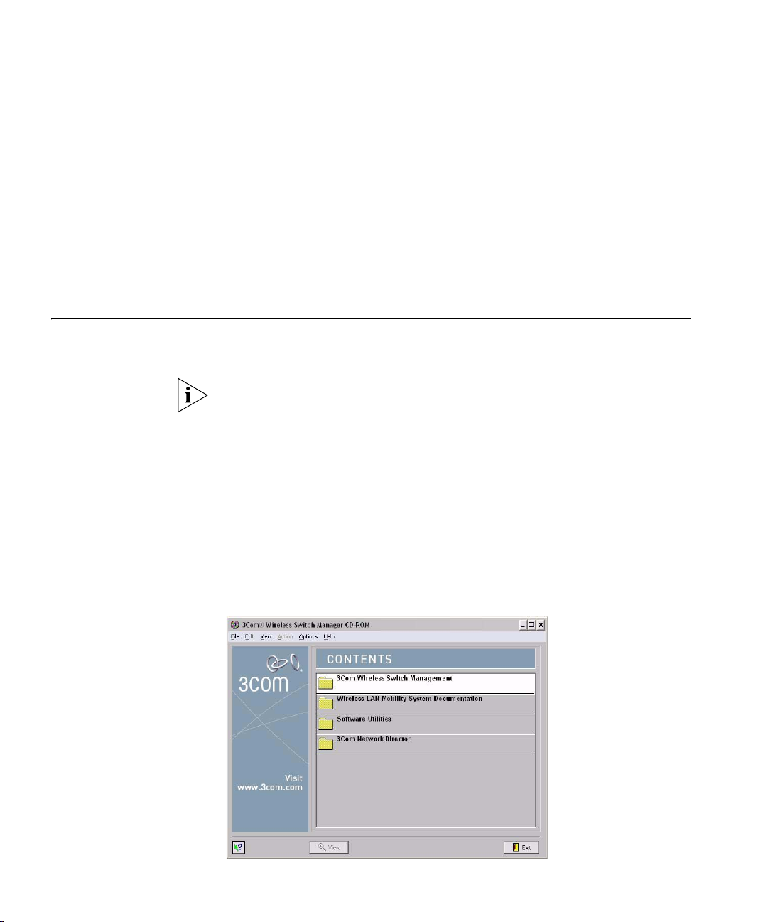
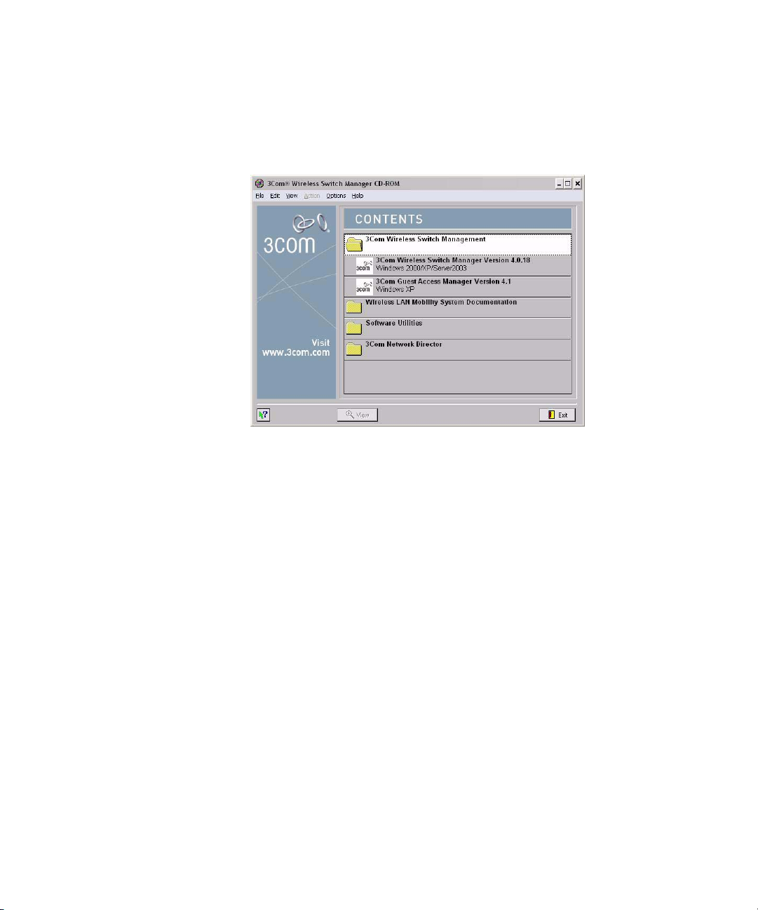
The Introduction page of the 3Com Wireless Switch Manager installation
wizard appears, and then the Contents screen appears, as shown below.
Installing 3WXM 25
2 Open the 3Com Wireless Switch Management folder.
3 Select 3Com Wireless Switch Manager.
4 Click the View button.
The 3Com Wireless LAN Switch Manager (3WXM) information screen
appears.
5 Click the Install button.
The installation begins. During the installation, the 3Com Wireless Switch
Manager installation wizard minimizes.
6 When the installation is complete, maximize the 3Com Wireless Switch
Manager installation wizard screen, and then press the Contents button.
7 Press the Exit button to close the wizard, or navigate to the other items
on the CD.
See “Getting Started” on page 47 for more information on getting
started with 3WXM.
26 CHAPTER 1: INSTALLING 3WXM
Installation Log File During installation, an installation log file, 3WXM_InstallLog.log, is
created and placed in the 3WXM installation folder. Double-click the log
file’s icon to read the log file. Have this log file available if you need to
contact 3Com Technical Support about an installation problem.
Upgrading 3WXM You can upgrade 3WXM by installing a newer version of 3WXM over a
previous version. You do not need to uninstall the previous version before
installing a newer version. Before you upgrade, 3Com recommends that
you make a backup of the config-db directory in the 3WXM installation
directory. As a best practice, back up the config-db directory on a regular
basis to ensure that you have copies of your network plans.
CAUTION: If you uninstall a previous version of 3WXM before
upgrading, make sure you note the serial number and license key from
the License Information dialog box, which you access by selecting
Help>Licensing from the main 3WXM window.
You can also save a copy of the license information by starting 3WXM
and clicking Save in the License Information dialog box.
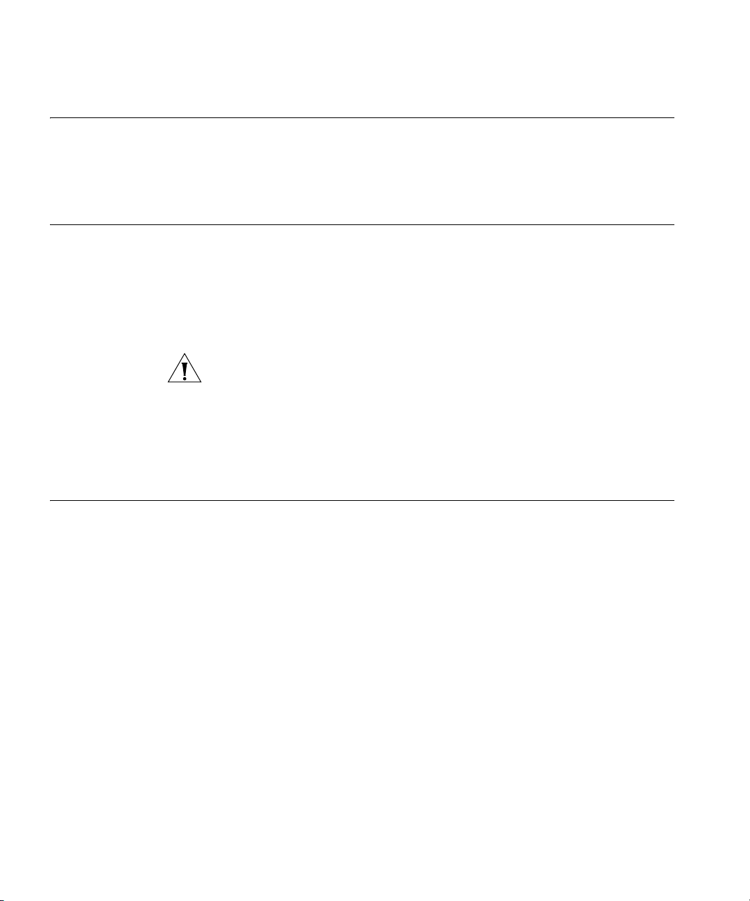
Uninstalling 3WXM You uninstall 3WXM by using its Uninstall wizard. Access the Uninstall
wizard from the 3Com program list in the Windows Start menu or the
Control Panel.
To uninstall 3WXM on Windows systems:
1 Access the Windows Control Panel, and select Add or Remove Programs.
2 Select 3WXM and click Change/Remove.
3 Click Uninstall.
The 3WXM Uninstall Options dialog appears.
Uninstalling 3WXM 27
By default, the following are removed when you uninstall the client
application:
Network plans
Access control
If the monitoring service was also installed, the monitoring service’s
database directory is also uninstalled by default. The database directory
contains the data collected by the monitoring service.
CAUTION: Do not delete the serial number unless specifically asked to do
so by 3Com Technical Support.
Your license(s) to use this software are registered against this serial
number. If you delete the serial number, the software will generate a new
serial number if it is ever reinstalled. You will then require new licenses to
register against the new serial number. If you delete the serial number,
the license information will also be deleted.
CAUTION: If you delete an item, the item is permanently lost. For
example, if you delete the database directory, all data collected by the
monitoring service is lost, including historical trend data.

28 CHAPTER 1: INSTALLING 3WXM
To prevent an item from being uninstalled, click on the checkbox next to
the item to remove the checkmark.
4 Click Continue.
The uninstall program reports its progress. When the uninstall process is
complete, the uninstall program reports that the items were successfully
deleted.
5 Click Done.
WORKING WITH THE 3WXM
2
USER INTERFACE
This chapter describes how to use the 3Com Wireless LAN Switch
Manager (3WXM) interface.
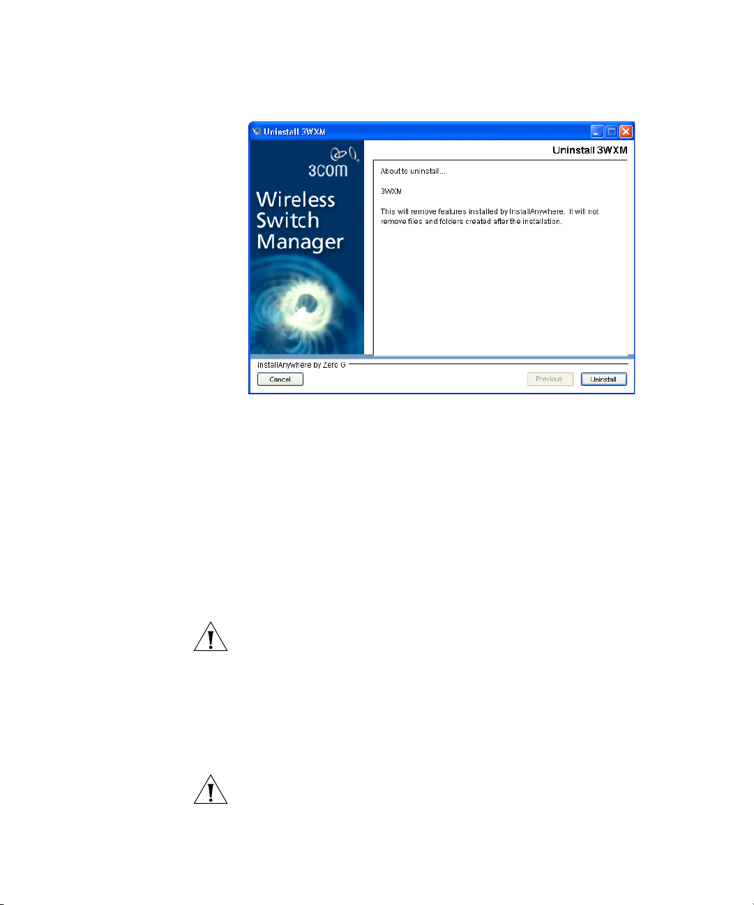
Overview When you start 3WXM client and log into 3WXM Services, the network
plan is displayed by the 3WXM client.
Organizer panel
Alerts panel
Content panel
Toolbar
Lock
icon

30 CHAPTER 2: WORKING WITH THE 3WXM USER INTERFACE
The network plan is the workspace in 3WXM you use to design and
manage a 3Com network. The network plan defines the following:
Network equipment (WX switches, MAPs, and third-party access
points)
Network site, including floor plans, RF characteristics of the floors, and
radio coverage
You can use the planning tool to define the network site and add the
equipment based on coverage and capacity needs. Alternatively, you can
add new or existing switches and access points individually.
Planning and equipment configuration, and network management, are
described in detail in other chapters of this manual. This chapter describes
the 3WXM user interface.
Display Panels The main 3WXM window contains the following display panels. (Their
locations are shown in the previous figure on page 34.)
Organizer panel
Alerts panel
Content panel
Task List panel
The main 3WXM window also contains a tool bar to navigate to major
features.
Organizer Panel The Organizer panel provides a tree-like view of the 3Com equipment
and site data managed by 3WXM.

Display Panels 31
The Organizer panel can contain the following object trees, depending
on the option selected on the tool bar:
Policies (displayed by the Policies tool bar option) — The set of device
configuration policies included in your network plan.
Equipment (displayed by the Configuration tool bar option) — The
set of devices in your network plan. This includes Mobility Domains,
3Com switches and MAPs, as well as third-party access points that
3WXM needs to be aware of while planning or monitoring the
network.
Sites (displayed by the RF Planning tool bar option) — Named sets of
buildings and floors where 3Com equipment is deployed.
The tree that is displayed depends on the active tool bar option. (See
“Tool Bar Options” on page 39.)

32 CHAPTER 2: WORKING WITH THE 3WXM USER INTERFACE
To expand the view of an object in the tree, click on the plus sign next to
the object. For example, to display the buildings in a site, click on the plus
sign next to the site name. To display the floors in the building, click next
to the building name, and so on.
Alerts Panel The Alerts panel displays summary statistics for configuration changes or
errors and for rogue devices. Click on a statistic to open the related tab in
the Content panel. The Alerts panel is located on the left side of the main
window, below the Content panel.
To navigate to more information and correct the warning or error, click
on the arrow to expand the panel, then click on the statistic to open the
corresponding tab in the Content panel.
Table 6 lists the types of alerts displayed in the Alerts panel.
Tab le 6 Alerts
Alert Category Description
Configuration Lists the number of configuration errors and warnings
encountered when 3WXM verifies WX switch configurations in
the network plan.
3WXM compares a switch’s configuration to a set of
configuration rules, and flags the items that must (error) or
should (warning) be corrected before deploying the switch
configuration from the network plan to the live network.
Select this alert to open the Config Verification tab in the
Content panel. You can use this tab to correct configuration
errors or disable rules.
(See “Verifying Configuration Changes” on page 363.)

Display Panels 33
Tab le 6 Alerts (continued)
Alert Category Description
Network Lists the number of configuration differences between all WX
switches in the network and their counterparts in the network
plan.
Select this alert to open the Network Verification tab in the
Content panel. You can use this tab to edit configuration items
or disable rules.
(See “Verifying Configuration Changes” on page 363.)
Rogue Detection Lists the total number of rogues detected by 3Com radios and still
operating in the Mobility Domain(s) defined in the network plan.
Select this alert to open the Rogue Detection tab in the Content
panel. You can use this tab to list information about non-3Com
wireless devices detected in the network.
(See “Detecting and Combatting Rogue Devices” on page 457.)
Local Changes Lists the number of WX switch configuration changes that have
occurred in 3WXM (in the network plan) since the last time the
switches in the network were synchronized with their
counterparts in 3WXM.
Select this alert to open the Managed Devices tab in the Content
panel. You can use this tab to review the local changes and
deploy them to the network.
(See “Synchronizing Local and Network Changes” on page 350.)
Network
Changes
Lists the number of WX switch configuration changes that have
occurred in the live network since the last time the switches in the
network were synchronized with their counterparts in 3WXM.
Select this alert to open the Managed Devices tab in the Content
panel. You can use this tab to review the network changes and
upload them to 3WXM.
(See “Synchronizing Local and Network Changes” on page 350.)
Content Panel The Content panel displays information or configuration settings, based
on the selected tool bar option. The Content panel is located to the right
of the Organizer panel. (See the figure on page 29.)
The Policies, RF Planning, and Configuration tool bar options display
configuration fields. After selecting one of these tool bar options, you can
click on a policy, WX switch, or site object in the Organizer panel to
display and configure settings for that object.
(For more information about the tool bar options, see “Tool Bar Options”
on page 39.)

34 CHAPTER 2: WORKING WITH THE 3WXM USER INTERFACE
Saving or Discarding Configuration Changes
When you select the Policies, RF Planning, or Configuration tool bar
option, the Content panel contains a Save button and a Discard button.
Save—Click Save to send unsaved configuration changes to 3WXM
Services to save in the network plan. The 3WXM client buffers
configuration changes you make to a policy, WX switch, or site until
you click Save or save the network plan. When you click Save, the
client sends all buffered configuration changes.
Discard—Click Discard to undo all buffered changes.
The Save and Discard buttons are greyed out unless there are unsaved
changes.
Configuration wizards have a Finish or OK button, which saves the
configuration items you type or select in the wizard.
When you save changes in a wizard by clicking Finish or OK, the Save
and Discard buttons in the Content panel remain greyed out because
there are no unsaved changes to save or discard.
When you click a link to open a configuration wizard, if there are unsaved
changes, 3WXM prompts you to apply or cancel the changes. Click
Apply to save the buffered changes and open the wizard.
The Save, Apply, Finish, and OK buttons do not send configuration
changes to the WX switches in the network. To send changes made in
the network plan to switches in the network, deploy the changes. (See
“Reviewing and Deploying Switch Configuration Changes”.)
Reviewing and Deploying Switch Configuration Changes
3WXM does not automatically deploy switch configuration changes from
the network plan to the actual switches in the network. The following
options in the Task List panel allow you to review and deploy changes:
Review—Displays a categorized list of the undeployed changes.
Deploy—Sends the changes to the network.
When you click Deploy, 3WXM verifies the configuration changes and
displays warnings or errors if applicable. If any errors are listed, 3WXM
does not deploy the changes.

Display Panels 35
To resolve errors and deploy the changes, use the Verification option. The
Verification option provides detailed information for errors and warnings
and enables you to resolve them. Generally, you can resolve an error or
warning by ignoring it or by clicking a link to open a configuration
wizard. (For more information, see “” on page 363.)
Task List Panel The Task List panel displays lists of tasks related to the object selected in
the Organizer panel. Click a task to open the configuration wizard
required to perform that task. The Task List panel is located to the right of
the Content panel. Here is an example of the task list for an individual
WX switch.
Configuration Wizards
When you click on a task in the Task List panel, 3WXM opens a
configuration wizard. For example, click on System Setup to open the
System Setup wizard for configuring basic switch parameters.

36 CHAPTER 2: WORKING WITH THE 3WXM USER INTERFACE
Some wizards contain multiple pages. Click the Next and Previous
buttons at the bottom of a wizard to navigate among the wizard’s pages.
The Finish button saves the changes. If applicable, saving the changes
also results in the newly configured object appearing in a table in the
Content panel. The following example shows the Wireless Service Profiles
table, which lists the SSID configurations on a switch.
The wizards displayed by selecting tasks in the Task List panel allow
configuration of settings that are essential or that are commonly
customized.

Display Panels 37
Properties Dialogs
To open a version of the configuration wizard that contains all the
configurable settings for the object, even ones that rarely need to be
changed, select the object in the table, then click Properties.
Resizing a Display
Panel
You can resize a panel by clicking and dragging the panel’s border, or by
clicking the resize icons (where applicable).
The resize icons listed in Table 7 are supported for panels displayed by the
RF Planning, Configuration, and Monitor tool bar options.
Tab le 7 Resize Icons
Option Description
Minimize the panel.
When the panel is minimized, the panel title is displayed as a tab.
Place the cursor over the tab to temporarily maximize the panel.
The panel is maximized only until you move the cursor away from
the panel. To make the panel stay maximized, click on the
maximize icon.
This option is supported on the Organizer and Task List panels.
Maximize the panel. This option makes the panel remain
maximized even when you move the cursor away.
This option is supported on the Organizer and Task List panels.
Maximize the Content panel. The panel fills the entire display area
and minimizes the Organizer and Task List panels.
This option applies only to the Content panel.
Restore the Content panel. The Organizer and Task List panels are
maximized and the Content panel is restored to its former size
between the other two panels.
This option applies only to the Content panel.
Panel sizes and window arrangements are associated with 3WXM
usernames. When you close 3WXM, 3WXM remembers the panel sizes
and window arrangements you assigned and restores them the next time
you run 3WXM.

38 CHAPTER 2: WORKING WITH THE 3WXM USER INTERFACE
Menu Bar Options Table 8 lists the options available from the menu at the top of the main
3WXM window. Click on a menu category to display the options for that
category.
Tab le 8 3WXM Menu Options
Menu Option Description
File Connect Log on to 3WXM Services.
Close Close the currently open network
plan.
New Network Plan Create a new network plan.
Switch Network Plan Close the currently open network
Delete Network Plan Delete a network plan.
Import Network Plan Import objects from another network
Save As Save a copy of the currently open
Import Import a WX configuration file into
Export Export a WX configuration file from
Exit Close 3WXM.
Tools Preferences Change 3WXM user preferences.
Performance Display Ethernet or radio statistics.
Certificate Management Manage certificates.
3WXM Services Setup Configure preferences for 3WXM
3WXM Services Backup/Restore Configure settings for backing up the
3WXM Services Lock
Management
plan and open another network plan.
plan into the currently open plan.
network plan under a new name.
the currently open network plan.
the currently open network plan.
Services.
database used by 3WXM Services, as
well as restore a previously backed-up
version of the database.
Display information about the lock
placed on the network plan and/or
delete the lock.

Tool Bar Options 39
Tab le 8 3WXM Menu Options (continued)
Menu Option Description
Help Help Open the online help (HTML version
of the 3Com WXM Reference
Manual).
You also can access the help by
pressing the F1 key.
Licensing Open the License Information dialog
box.
Report Problem Report a problem to 3Com Technical
Support.
About 3WXM About 3WXM:
3WXM version information
Memory usage
Java garbage collection (Force GC)
Tool Bar Options Table 9 lists the options available from the tool bar of the main 3WXM
window. Click on an option to open the data or tabs for that option.
Some tool bar options fill the Content panel. Others fill the entire
window area under the tool bar.
The larger icons provide access to 3WXM features. The smaller icons
underneath the Back and Forward icons apply to the 3WXM application itself.
Tab le 9 3WXM Tool Bar Options
Option Description
Back Page back through the previously selected tool bar
Forward Page forward through previously selected tool bar
Policies Display the tree of configured policies in the Organizer
options or Organizer panel tree selections.
options.
panel.
To display the configuration settings in a policy, click on
the policy. The settings appear in the Content panel.
To create a new policy, click Policy in the Task List
panel.
(See “Configuring and Applying Policies” on page 373.)

40 CHAPTER 2: WORKING WITH THE 3WXM USER INTERFACE
Tab le 9 3WXM Tool Bar Options (continued)
Option Description
RF Planning Display the tree of configured sites in the Organizer
Configuration Display the tree of configured devices in the Organizer
Devices Display a list of the WX switches in the network plan.
Monitor Display status information and statistics for equipment
Rogue Detection Display information about rogue or interfering devices
panel.
To display information about a site or an object in
that site, click on it. The information appears in the
Content panel.
To perform site-related tasks, click task links in the
Task List panel.
(See “Planning the 3Com Mobility System” on page 69.)
panel.
To display information about a device or a
configuration area within that device, click on it. The
information appears in the Content panel.
To perform device-related tasks, click task links in the
Task List panel.
(See “Configuring WX System Parameters” on
page 157.)
To upload, restart, or change the management
status of switches, view scheduled tasks, or distribute
certificates, use the Device tab.
To review and either allow or disallow local and
network changes, or to schedule configuration
deployment, use the Changes tab.
To manage and distribute MSS software images, use
the Image tab.
(See “Managing WX System Images and
Configurations” on page 345.)
or site objects selected in the Organizer panel.
(See “Monitoring the Network” on page 401.)
detected by MAP radios. This option also provides tools
for tuning rogue detection settings and for issuing
countermeasures against rogues.
(See “Detecting and Combatting Rogue Devices” on
page 457.)

Tool Bar Options 41
Tab le 9 3WXM Tool Bar Options (continued)
Option Description
Verification Display the Config Verification and Network Verification
tabs. The Verification tabs enable you to troubleshoot
configuration issues on WX switches in the network
plan or in the live network.
To display more information about an error or
warning message, click on the row containing the
message.
To resolve the situation causing the message or to
ignore the message, select options in the Resolutions
area of the tab.
(See “Verifying Configuration Changes” on page 363.)
Events Display the events log. The log includes events
generated by 3WXM Services and events generated by
the managed WX switches in the network plan.
To filter the message list, use the Filters tab.
To display more information about a message, click
on the row containing the message, then use the
Details tab.
(See “Using the Event Log” on page 377.)
Reports Display links for configuring and generating reports.
(See “Generating Reports” on page 383.)
The following icons are smaller and are located underneath the Back and
Forward icons.
Exit the application Close 3WXM.
Edit application
preferences
Open a dialog to configure 3WXM client preferences.
(See “Changing 3WXM Preferences” on page 481.)
Configure 3WXM Services Open a dialog to configure 3WXM Services.
(See “Changing 3WXM Services Preferences” on
page 491.)
Launch 3WXM HTML
Open the online help (HTML version of this document).
Help

42 CHAPTER 2: WORKING WITH THE 3WXM USER INTERFACE
Copying, Pasting, and Deleting Objects
Copy and Paste in the
Organizer Panel
You can copy, paste, and delete objects in the Organizer panel or in the
Content panel. In the Organizer panel, right-click on an object to display
a menu with the following options:
Copy—Copy the selected object and its child objects to the clipboard.
Paste—Add the object(s) in the clipboard to the selected object.
Paste Replace—Replace the like-named object(s) in the selected
object with the object(s) in the clipboard.
Delete—Remove the selected object from the network plan.
Use the Copy and Paste options to create a new object. Use the Copy
and Paste Replace options to replace an object with a copy of another
instance of the same type of object.
You also can copy and paste objects listed in tables in the Content panel
using the copy and paste icons. (See “Copy and Paste in the Content
Panel” on page 43.)
To delete an object in a table, select the object, then click Delete.
To create a new object in the Organizer panel:
1 Select the object you want to copy in the Organizer panel.
2 Right-click on the object and select Copy.
3 Select the parent object where you want the copy to go.
4 Right-click on the parent object and select Paste.
A configuration wizard appears, where you can modify the name of the
object and other parameters as applicable. When you are finished, the
new copy of the object appears under the parent object.

Copying, Pasting, and Deleting Objects 43
Copy and Paste
Replace in the
Organizer Panel
Copy and Paste in the
Content Panel
To replace an object with the Copy and Paste Replace options:
1 Select the object you want to copy in the Organizer panel.
2 Right-click on the object and select Copy.
3 Select the object you want to replace.
4 Right-click on the parent object and select Paste Replace.
A configuration wizard appears, where you can modify the name of the
object and other parameters if needed. When you are finished, the
replaced object is removed and the copied object appears under the
parent object.
1 Select the objects (rows).
To select a single object, click on the row for the object.
To select multiple contiguous objects, click Shift while selecting
them.
To select multiple noncontiguous objects, click Ctrl while selecting
them.
2 Click the copy icon ( ).
3 Click the paste icon ( ).
A configuration wizard appears.
4 Edit settings to make the new object unique from the object you copied,
then click OK or Finish to save the changes and close the configuration
wizard.

44 CHAPTER 2: WORKING WITH THE 3WXM USER INTERFACE
Enabling Keyboard Shortcut Mnemonics (Windows XP Only)
Keyboard shortcut mnemonics (also called action mnemonics) in 3WXM
underline shortcut characters in action names in toolbars and menus.
When a character is underlined, you can press the corresponding letter
key on the keyboard to display the toolbar menu or perform the menu
action. Depending on your Windows XP desktop setup, 3WXM might not
show action mnemonics.
To enable action mnemonics:
1 Right-click on the desktop, and select Properties.
2 Click the Appearance tab. The Display Properties dialog box appears.
3 Click Effects.

Enabling Keyboard Shortcut Mnemonics (Windows XP Only) 45
4 Clear the box labeled Hide underlined letters for keyboard
navigation until I press the Alt key.
Clearing this option allows programs to show the underlined character
for mnemonics in 3WXM.
5 Click OK.
6 In the Display Properties dialog box, click OK.

46 CHAPTER 2: WORKING WITH THE 3WXM USER INTERFACE

GETTING STARTED
3
This chapter contains information about starting 3Com Wireless LAN
Switch Manager (3WXM), restricting access to 3WXM, creating and
managing network plans, and defining a Mobility Domain.
Starting 3WXM The following steps describe how to start 3WXM.
You must install a license key and activation key for the server before you
can connect to the server and work with network plans. To license a
server, you must start the 3WXM client on the same machine where the
server is installed.
1 Select Start > Programs > 3Com > 3WXM > 3WXM, or double-click
the 3WXM icon on the desktop.
The 3WXM Service Connection dialog appears.
2 Click Next.
If a Certificate Check dialog appears, click Accept.

48 CHAPTER 3: GETTING STARTED
If this is the first time you are starting 3WXM, or you have not yet
activated your license, the client will not establish a connection to the
server when you click Next. Instead, the client will briefly contact the
server, then display the following message: Error: Missing license.
If you need to install license information, click Cancel to close the
If you have already installed license information, go to step 15.
3 Select Help > Licensing from the tool bar. The License Wizard is
displayed.
dialog and go to step 3.
4 If you are installing a licensed copy, select Standard Base Product and
click Next. Go to step 5.
If you are installing an evaluation copy:
a Select Time Limited Evaluation and click Next.
b Click Finish and go to step 13.
5 Type the license key that was supplied with the 3WXM CD, and click
Next.
6 Click Get Activation Key. A 3Com web page appears. Enter your
registration information (and the license key, if you are licensing a
purchased copy) in order to obtain an activation key.
7 Copy the activation key from the web page and paste it onto the
Activation Key box of the Activation Key page.

Starting 3WXM 49
8 If you plan to manage 10 or fewer wireless LAN switches, click Finish and
go to step 13.
If you plan to manage more than 10 wireless LAN switches, click Next
and go to step 9.
If you are activating an evaluation copy, you can manage up to 10
wireless LAN switches.
9 Type the upgrade license key in the License Key box and click Next.
10 Click the Get Activation Key to access the product activation key for
your upgrade license. Register your upgrade license in order to obtain its
activation key.
11 Copy the activation key for the upgrade license from the web page and
paste it into the Activation Key box of the Activation Key page.
12 Click Finish.
13 To connect to the server, select File > Connect from the menu bar. The
3WXM Services Connection dialog box appears.
14 In the 3WXM Services Connection dialog box, enter the IP address of a
host running 3WXM Services (leave this as 127.0.0.1 if the services are
being run on this host), and then click Next.
15 After a connection is established to the specified 3WXM Services host, do
one of the following:
Edit the currently loaded network plan. The first time you start 3WXM,
a network plan called Default is opened.
Create a new network plan.
If you select this option, wizard pages guide you in setting up a
network plan. For more information, see “Creating a Network Plan”
on page 54.
Switch to an existing network plan. You can open the sample plan
included with 3WXM or a plan that you or another 3WXM user has
saved on the 3WXM Services host.

50 CHAPTER 3: GETTING STARTED
Restricting Access to 3WXM
By default, all users who have been successfully authenticated to a system
with 3WXM installed on it can run 3WXM. You can restrict the users
allowed to access 3WXM on a system and define their access privileges
by creating three types of 3WXM user accounts:
Administrator—This account can monitor the network, configure
the network, and administer 3WXM. When creating an administrator
account, you must assign an administrator password, which you are
required to provide the next time you configure access privileges. This
account also can remove locks.
Provision—This account can configure and monitor the network.
However:
On the File menu, the New, Switch Network Plan, and Delete
Network Plan options are greyed out.
All configuration options in the 3WXM Services Setup dialog box
are greyed out.
Monitor—This account can only monitor the network. When users
with a monitor account open a network plan, they can see
configuration changes that have been deployed to the network. Any
configuration changes that have not been deployed are not visible.
On the File menu, all options except Open, Close, and Exit are
greyed out.
On the Tools menu, the Certificate Management option is greyed out.
All tasks for creating configuration items are greyed out.
All configuration options in the 3WXM Services Setup dialog box
are greyed out.
Options to deploy and undo local changes and accept or undo
network changes are not available.
The options on the right-click menu in the Organizer panel are
greyed out.
Configuration items that are related specifically to monitoring
(logs, managed devices, site surveys and work orders) can be
configured. However, new network plans cannot be configured.
The 3WXM user accounts you create must also exist in the Windows
domain or local operating system. Otherwise, those users cannot start
3WXM.

Restricting Access to 3WXM 51
Creating an
Administrator
Account
Before you can restrict user access to 3WXM, you must create an
administrator account. After creating an administrator account, you can
create provision or monitor accounts.
To create an administrator account:
1 Select Tools > 3WXM Services Setup. The 3WXM Services Setup dialog
box appears.
2 In the Access Control section of the dialog box, de-select Allow All
Users.
3 Type a new password for the administrator (1 to 80 alphanumeric
characters, with no spaces or tabs). The password is case-sensitive.
4 Type the administrator password again for verification.
5 Click OK.
6 In the 3WXM Services Setup dialog box, click Save to save the changes.
If this is the first user account, 3WXM Services inserts the username you used
to log onto the machine that is running 3WXM Services in the Account
Name box. However, you are not required to use this name. In fact, you are
not required to use a name that matches a user account on the machine.
3WXM Services automatically makes the first user account you add an
Admin account.

52 CHAPTER 3: GETTING STARTED
Creating Provision or
Monitor Accounts
Deleting 3WXM User
Accounts
After creating an administrator account, you can create provision or
monitor accounts. To create a provision or monitor account:
1 Access the 3WXM Services Setup dialog box.
2 To add a provision user account, click Add Provision Account. To add a
monitor account, click Add Monitor Account. The Add Account dialog
box appears.
3 Type the name of a user account that has access to the system.
4 Type a new password for the user (1 to 80 alphanumeric characters, with
no spaces or tabs). The password is case-sensitive.
5 Type the password again for verification, and then click OK.
6 In the 3WXM Services Setup dialog box, click Save to save the changes.
7 Click Close to close the dialog box.
To delete a 3WXM user account:
1 Access the 3WXM Services Setup dialog box.
2 Select a user account from the Authorized Users list.
3 Click Remove an Account. The account is deleted.
4 In the 3WXM Services Setup dialog box, click Save to save the
changes.
Disabling Access
Control
5 Click Close to close the dialog box.
If you have enabled access control for 3WXM, you can disable access
control. This allows all users who have successfully authenticated to the
system on which 3WXM is installed to run 3WXM.
If you disable access control, the permissions and account types are
deleted from 3WXM. However, these deletions have no effect on the
Windows user accounts themselves.
To disable access control:
1 Access the 3WXM Services Setup dialog box.
2 Click Allow all users. All 3WXM accounts that were created are deleted.
3 In the 3WXM Services Setup dialog box, click Save to save the changes.
4 Click Close to close the dialog box.

4
4
WORKING WITH NETWORK PLANS
A network plan is the workspace in 3WXM you use to design a 3Com
network. In a network plan, you define components of the network (WX
switches, MAP access points, and optional third-party access points).
Regardless of whether you intend to use physical planning features, you
must create a network plan before you can configure or manage WX
switches or monitor network data.
A network plan allows modular management of large networks based on
organizational or geographical boundaries. For example, a network plan
can represent a campuswide network. You also can define a physical
representation of the network (sites, buildings, and floors). In this case,
you can import drawings of your floor plans into the network plan or
draw plan details manually. You can then identify the RF characteristics
by importing data from a site survey or by manually identifying RF
objects.
3Com recommends that you limit a network plan to a single campus or
Mobility Domain (3Com network domain).
Different countries have different regulatory limits for 802.11 radios.
Setting the country code in the network plan automatically enforces the
appropriate regulatory limits for all configured radios. The greatest
geographical scope for a network plan is a country, because a network
plan is based on one specific country code.
54 CHAPTER 4: WORKING WITH NETWORK PLANS
Creating a Network Plan
To create a network plan:
1 From the main 3WXM window, select File > New. The Create Network
Plan wizard appears.
2 In the Network Plan Name box, type a name for the network plan. You
can use 1 to 60 alphanumeric characters, with no spaces, tabs, or any of
the following: slash (/), backslash (\), quotation marks (“ ”), asterisk (*),
question mark (?), angle brackets (< >), or vertical bar (|).
3 In the Country Code list, select the country where the network is to be
deployed.
You must select a country code before continuing. The country code you
select here is the default for all MAPs in the network plan. However, you
can override the country code in individual sites within the network plan.
4 In the Channel Set list, select the set of operating channels for any
802.11b/g MAP radios you plan to use.
The choices in the list are dependent on the country code you chose in
step 3. The channel numbers you select are used later in the planning
process when you assign channels to 802.11b/g radios.
You might be able to select a set of overlapping channels. However, in
some network layouts, using overlapping channels reduces network
performance.
Channel numbers used for 802.11a radios do not overlap and are not
listed at this stage of the planning process. You can modify channel
selections for 802.11a and 802.11b/g radios later in the planning process
or allow WX switches to set the channels automatically.
The 802.11b/g channel set you select here is the default for all MAPs in
the network plan. However, you can override the channel set in individual
sites within the network plan.
5 Click Next to save the network plan on the server and open it in 3WXM.
The network plan settings appear in the Content panel and the following
links appear in the Task List panel:
Mobility Domain—Configure a named set of WX switches that
support user roaming. (See “Creating a Mobility Domain” on
page 62.)

Managing Network Plans 55
Wireless Switch—Use a wizard to configure basic switch
parameters. (See “Using the Create Wireless Switch Wizard” on
page 165.)
Third-Party AP—Add a third-party AP for use in network planning.
(See “Creating a Third-Party AP” on page 63.)
Country Code—Change the regulatory domain for the MAPs in
the network plan. (See “Changing the Country Code” on
page 65.)
Auto-Tune Settings—Update the channel and power information
in the network plan to match the channel and power settings
assigned to MAPs in the network by the RF Auto-Tune feature.
(See “Applying the Network’s RF Auto-Tuning Settings to the
Network Plan” on page 65.)
Upload Wireless Switch—Add a WX switch that is already
deployed in the live network to the network plan. (See “Uploading
a WX Switch into the Network Plan” on page 66.)
Convert Auto APs—Convert MAPs that were configured by an
Auto-AP profile into statically configured MAPs. (See “Converting
Auto DAPs into Statically Configured APs” on page 67.)
Managing Network Plans
Saving a Network
Plan
Network Domain—Configure a group of Mobility Domains into a
single Network Domain. (See “Creating a WX Switch” on
page 63.)
After creating a network plan, you can save, close, open, or delete it. You
can also share a network plan with others.
When you create a network plan and save changes, a directory with the
same name as the network plan is created in the config-db directory of
the 3WXM installation directory on the 3WXM Services host.
Each time you save a configuration change, 3WXM saves the changes to
the network plan. You do not need to explicitly save the network plan
itself. However, if the network plan has unsaved changes when you select
to exit 3WXM or close a network plan, 3WXM displays a prompt to ask
whether you want to save or discard the changes, or cancel the request.
(See “Saving or Discarding Configuration Changes” on page 34.)

56 CHAPTER 4: WORKING WITH NETWORK PLANS
3Com recommends that you regularly back up the config-db directory so
that you have additional copies of your network plans.
(In addition to this section, see “Managing Network Plans” on page 503.)
If the plan has unsaved changes and 3WXM Services becomes
unavailable before the changes are saved, 3WXM client buffers the
changes until 3WXM Services becomes available again. However, for the
changes to be buffered, you must leave your 3WXM client session open
and leave the network plan open.
Saving a Network Plan with a New Name
You can save a network plan with a new name by using the Save As
feature.
To save a network plan with a new name:
1 In the main 3WXM window, select File > Save As. The Save As Network
Plan wizard appears.
2 In Specify Plan Name, type a new network plan name.
Opening a Network
Plan
Optionally, you can select an existing network plan name to replace it.
3 Click Next. You see the status of the save process.
4 Click Finish.
Network plans reside on a host running 3WXM Services. You can open
an existing network plan by connecting to the 3WXM Services host
where the plan resides, selecting File > Switch Network Plan, then
specifying the plan’s name in the dialog. The network plan is then
opened in the 3WXM main window.
You can open a network plan created in a previous version of 3WXM
with a later version of 3WXM. For example, if you created a network plan
in 3WXM Version 4.0, you can open the plan in 3WXM Version 4.1.
However, because a network plan created in 3WXM Version 4.0
manages WX switches running MSS Version 4.0, you cannot use new
features available in MSS Version 4.1 unless you upgrade the WX
switches to MSS Version 4.1. (To upgrade WX switches, see “Distributing
System Images” on page 354.)

Managing Network Plans 57
To open a network plan:
1 Establish a connection to the 3WXM Services host on which the network
plan is saved.
You can do this by restarting 3WXM or selecting File > Open, and then
entering the IP address of the 3WXM Services host in the 3WXM Services
Connection dialog box.
2 After the connection is established with the 3WXM Services host, select
File > Switch Network Plan.
If any changes were made to the currently loaded network plan, you are
prompted to save them and close the file. The Switch Network Plan
dialog box appears.
3 Select the network plan you want to open and click Next.
3WXM establishes a new connection to the host running 3WXM Services
and loads the specified network plan.
Importing a Network
Plan
You can import objects from another network plan into the currently
open plan. When you import objects from another plan, objects are
added to the currently open plan as follows:
If an object (object name) exists in the plan you are importing but not
in the open plan, the object is added to the open plan.
If an object (object name) exists in both plans, the copy of the object
in the imported plan replaces the object in the open plan.
If both plans have the same floor name, the floor in the plan you
are importing completely replaces the floor of the same name in
the other plan.
3Com recommends that you save a backup copy of the plan before
importing objects from another plan. To save a backup copy, you can use
the File > Save As option.
To import a plan:
1 In the main 3WXM window, select File > Import Network Plan.
2 Select the network plan you want to import, from the Select Plan
drop-down list.

58 CHAPTER 4: WORKING WITH NETWORK PLANS
3WXM compares the object names in the plan to be imported with the
object names in the open plan. If both plans have objects of the same
name and type, the objects are listed and Conflict appears in the Status
column.
3 Do one of the following, depending on whether you want to import all
objects from the plan:
If you do not want to replace the objects in the open plan with their
like-named objects in the other plan, click Close. 3WXM does not
import any objects from the plan.
If you do want to replace the objects, click Import Plan. 3WXM
imports the objects into the open plan. Click Close.
Closing a Network
Plan
Deleting a Network
Plan
You can close a network plan at any time. If you have unsaved changes,
you are asked whether you want to save the changes.
To close a network plan:
1 In the main 3WXM window, select File > Close or File > Exit.
If the network plan has no unsaved changes, the network plan is closed.
Otherwise, go to the next step.
2 If there are unsaved changes, 3WXM displays a dialog asking whether
you want to save the changes, discard them, or cancel the request to
close the plan or exit the application. Do one of the following:
Select Apply to save the changes and close the plan.
Select Discard to close the plan without saving the changes.
Select Cancel to cancel the request to close the plan or exit the
application, and continue working with the plan.
You can delete a network plan at any time.
CAUTION: The Delete Network Plan wizard has a Cancel button, but this
button does not cancel deletion of a network plan. 3WXM deletes the
plan as soon as you click Next.
You cannot delete the currently active plan. To delete the active plan, first
use the File > Switch Network Plan option to select another plan to be
active, then delete the plan.

Managing Network Plans 59
To delete a network plan
1 In the main 3WXM window, select File > Delete Network Plan. The
Delete Network Plan wizard appears.
2 Select the network plan you want to delete from the list.
3 Click Next. The network plan is deleted.
4 Click Finish.
Sharing a Network
Plan
Since the 3WXM plan repository resides on a networked server (the host
running 3WXM Services), you can easily share access to network plans
among hosts running the 3WXM client.
When you make changes to a network plan, 3WXM locks the part of the
plan you are modifying. Other 3WXM clients can still open the network
plan, but the lock prevents the other clients from modifying the part of
the plan you are already modifying. The lock remains in effect until your
modification is saved. 3WXM then removes the lock.
When a user with an administrator or provision account tries to access a
part of a plan that is already locked by another user, 3WXM displays the
Lock Info page. The Lock Info page indicates who has locked the network
plan. You can optionally override the user’s lock. Note that only a user
with Administrator privileges can override another user’s lock.
To override another user’s lock
1 Select Tools > 3WXM Services Lock Management. The 3WXM
Services Lock Management dialog box appears.
2 Select the lock you want to delete and click on Delete Lock. (Only an
Administrator can delete a lock.)
3 A message is displayed indicating that the user whose lock you selected
will not be able to save their changes when you delete their lock. Click
Yes to confirm that you want to do this.
If you override the lock, 3WXM unlocks the part of the plan that was
locked, and notifies the other 3WXM users about the lock change. From
this point on, the former lock holder cannot save changes to the
previously locked portion of the plan.
By default, 3WXM sends a message to all users who have the plan open
with monitor access to inform them when changes are saved to the plan.
In addition, 3WXM sends a message to each monitor user, so that one of
them can then edit the plan.

60 CHAPTER 4: WORKING WITH NETWORK PLANS
To disable notification
1 In the main 3WXM window, select Tools > Preferences.
2 Click the Persistence tab.
3 To disable change notification, clear Plan Change Notification.
4 Click Close.
Defining a Mobility Domain
A Mobility Domain is a collection of WX switches that work together to
support roaming users. One of the WX switches is defined as a seed
device, which distributes information to the other WX switches defined in
the Mobility Domain.
A Mobility Domain allows users to roam geographically from one WX
switch to another without losing network connectivity. Users connect as
a member of a VLAN through their authorized identities. If the native
VLAN for a user is not present on the WX to which the user connects, the
WX creates a tunnel to that VLAN.
A network plan can contain more than one Mobility Domain. Standalone
WX switches and third-party APs do not need to be configured within a
Mobility Domain.
You use 3WXM to create a Mobility Domain and define its seed device
and the other WX switches in the Mobility Domain. If you already have
WX switches installed and configured, you can upload the configurations
of the switches to 3WXM to have them included in a Mobility Domain.
Roaming Behavior For a client session to be considered a roaming session (and not a new
session), the following criteria must be met:
The client associates or reassociates with a MAP in the Mobility
Domain, and the client already has a session on a different MAP in the
Mobility Domain. The existing session can be in one of two states:
Active—The normal state for a client that has left radio range
without sending a request to disassociate.
Diassociated—The state of a client that has sent an 802.11
disassociate frame, but has not roamed or aged out yet.

Defining a Mobility Domain 61
Mobility Domain communications are stable. Generally, the
communications required for roaming are the same as those required
for VLAN tunneling. Roaming between ports on a WX is possible even
if the Mobility Domain is down.
Authentication, authorization, and accounting (AAA) on the MAP to
which the client roams is successful on the first attempt. An
authentication or authorization failure clears the client session.
Depending on when the failure occurs, roaming can be disqualified or
delayed.
The client uses the same authorization parameters for the new session
as for the old session. For example, changing the Encryption-Type or
VLAN-Name parameter might cause a new session to be recorded,
rather than a roam within the same session.
A disassociated session has a grace period of 5 seconds in which the
session history can be retrieved and forwarded. After 5 seconds, the
session is cleared, and its accounting is stopped. You cannot configure
the grace period.
If the client MAC address in a Mobility Domain is not found in 5 seconds,
the session is considered new.
The 802.1X reauthentication timeout has little impact on roaming. If the
timeout lapses, 802.1X processing is performed on the existing
association. Accounting and roaming history are not affected if the
reauthentication is successful, because the client is still associated with
the same MAP. If reauthentication fails, the session is cleared, and it is
not eligible for roaming. If the client associates to the same MAP, that is
recorded as a new session.
Roaming creates the following effects:
Remote Authentication Dial-In User Service (RADIUS) accounting is
treated as a continuation of an existing session, rather than a new
one.
For tracked users, you can view roaming history in the Monitor tab.
See “Using the Client Monitor View” on page 415.
The old session is cleared from the WX, even if the client did not
explicitly disassociate from the MAP and the 802.1X reauthentication
interval has not lapsed.

62 CHAPTER 4: WORKING WITH NETWORK PLANS
Traffic Ports Used by
a Mobility Domain
When deploying a Mobility Domain, you might attach the WX switches to
subnets that have firewalls or access controls between them. Within a
Mobility Domain, the WX switches exchange information and other types
of traffic, depending on your configuration of AAA and various
management services.
Table 10 provides a summary of the traffic ports typically used by a
Mobility Domain and its associated AAA and management functions.
Table 10 Traffic Ports Used for AAA Servers and Management Servers
Protocol Port Function
IP/UDP (17) 1812 RADIUS authentication (default setting)
IP/UDP (17) 1813 RADIUS accounting (default setting)
IP/TCP (6) 443 Secure Sockets Layer protocol (SSL)
management using Web Management
IP/TCP (6) 8889 SSL management using 3WXM
IP/TCP (6) 23 Telnet management
IP/UDP (17) 161 SNMP get and set operations
IP/UDP (17) 162 SNMP traps
IP/ICMP (1) N/A Several types (for example, ping)
IP/UDP (17) 123 Network Time Protocol (NTP)
IP/UDP (17) 53 Domain Name Service (DNS)
Creating a Mobility
Domain
The traffic typically sent between WX switches within a Mobility Domain
uses IP/UDP protocol 17 traffic on port 8817 for both source and
destination. Roaming traffic uses IP protocol 4.
The Create Mobility Domain wizard requires you to select the switches to
place in the Mobility Domain and to select the seed switch. Add the
switches to the network plan before you configure the Mobility Domain.
1 Select the Configuration tool bar option.
2 Select the network plan in the Organizer panel.
3 Select the Mobility Domain task in the Task List panel. The Create
Mobility Domain wizard appears.
4 In the Name box, type the name for the Mobility Domain (1 to 16
characters, with no spaces or tabs).
5 Click Next.

Creating a WX Switch
Creating a WX Switch 63
6 In the Available Devices list, select the WX switches you want to add to
the Mobility Domain.
7 Click Next.
8 Select the switch to act as the seed switch for the Mobility Domain.
9 Click Finish.
1 Select the Configuration tool bar option.
2 In the Organizer panel, select the network plan name.
3 In the Task List panel, select Wireless Switch.
4 Go to “Using the Create Wireless Switch Wizard” on page 165.
Creating a Third-Party AP
You can add a third-party AP to the network plan’s equipment list.
When you use RF Planning, you can place the AP on its location on a floor
plan. In this case, 3WXM take the AP’s channel number into account
when assigning channels to MAPs.
1 Select the Configuration tool bar option.
2 Select the network plan in the Organizer panel.
3 Select the Third Party AP task in the Task List panel. The Create Third
Party AP wizard appears.
4 In the Name box, type a name for the access point. You can use 1 to 32
characters, with no punctuation except the following: period (.), hyphen
(-), or underscore (_).
5 Optionally, in the Manufacturer ID box, type the manufacturer
identification for the access point (1 to 30 characters, with no spaces).
6 In the Product ID box, type the product identification for the access point
(1 to 30 characters, with no spaces).
7 In the IP Address box, type the IP address for the access point.
If you specify an IP address, you can use Telnet and a Web browser with
this access point.
8 In the Telnet Port Number box, specify the port number for Telnet service.

64 CHAPTER 4: WORKING WITH NETWORK PLANS
9 In the HTTP Port Number box, specify the port number for HTTP service.
10 Click Next.
11 In the AP Model drop-down list, select one of the following:
AP (Dual Radio)—802.11a and 802.11b or 802.11b/g
AP (Single Radio)—802.11a, 802.11b, or 802.11g
12 In the Radio Type drop-down list, select one of the following: 11a, 11b,
11g.
The choices available depend on the selection you made in step 11.
13 Click Next.
14 Verify the radio slot number and radio type.
For a dual-radio access point, 802.11b/g radios have a slot number of 1.
802.11a radios have a slot number of 2.
15 In the Channel Number list, select the channel number for the radio.
16 In the Transmit Power box, specify the transmit power for the radio.
17 To enable the radio, select Enabled.
The access point’s radio must be enabled in order to be considered in
channel allocation.
18 In the SSID box, type the service set identifier (SSID) for the radio.
19 In the MAC Address box, type the MAC address of the radio.
20 In the Antenna Gain list, select the antenna gain for the radio.
21 If the access point has only one radio, click Finish. Otherwise, go to
step 22.
22 Click Next. The Radio A page appears.
23 Repeat step 14 through step 20 for the 802.11a radio.
24 Click Finish to save the changes.
25 To place the AP on a floor plan, see “Moving a Third-Party AP Icon to its
Floor Location” on page 131.

Changing the Country Code 65
Changing the Country Code
Applying the Network’s RF Auto-Tuning Settings to the Network Plan
The country code determines the valid radio types as well as channel
numbers and power settings for MAP radios. The country code is one of
the parameters you set when you create a network plan. If you need to
change a plan’s country code, use the following procedure.
1 Select the Configuration tool bar option.
2 In the Organizer panel, select the network plan name.
3 In the Task List panel, select Country Code. The Change Country Code
wizard appears.
4 Select the country code from the drop-down list.
5 Click Next.
3WXM changes the country code on all the WX switches in the network
plan, and lists its progress as it does so.
6 Click Finish.
If RF Auto-Tuning is running on MAP radios in the network, you can
update the radios in the network plan with the channel and power
settings currently in effect on the same radios in the network. You also
can lock down the channel and power settings in the plan and in the
network by disabling RF Auto-Tuning on the radios.
RF Auto-Tuning settings are applied only to configured MAPs, not to
Auto DAPs (Distributed MAPs configured using a Distributed MAP
profile).
This option also disables RF Auto-Tuning on the radios. When
RF Auto-Tuning is disabled, the channel and power settings on the radios
are static.
1 Select the Configuration tool bar option.
2 In the Organizer panel, select the network plan name.
3 In the Task List panel, select Auto-Tune Settings. The Apply Auto-Tune
Settings wizard appears.
4 Select the RF Auto-Tuning settings you want to apply. Both channel and
power settings are selected by default.

66 CHAPTER 4: WORKING WITH NETWORK PLANS
5 Select the scope:
Mobility Domain
WX switch
Radio profile
Individual MAP radio
To select a radio profile, display it first by clicking on the plus sign next to
the WX switch. To select an individual radio, display it first by displaying
its radio profile, then clicking on the plus sign next to the radio profile.
6 If you accessed the wizard from the toolbar, select the scope. You can
select a Mobility Domain, WX switch, MAP, or radio profile.
7 Click Next. The progress is displayed.
8 Click Finish.
Uploading a WX Switch into the Network Plan
1 Select the Configuration tool bar option.
2 In the Task List panel, select Upload Wireless Switch.
3 In the IP Address box, type the IP address for the WX switch.
4 In the Enable Password box, type the enable password for the WX switch.
This password must match the enable password that was defined using
the CLI command set enablepass. For more information, see the
Wireless LAN Switch and Controller Configuration Guide.
5 Click Next. The uploading progress is shown.
6 After the Successfully uploaded device message is displayed, click Next.
3WXM uses its verification rules to check the switch’s configuration. If an
item in the configuration generates an error or warning, 3WXM displays
the error or warning message.
7 Review the verification messages to determine whether you will need to
make changes to the switch’s configuration after uploading it into 3WXM.
8 Click Next.
9 Click Finish.
10 If 3WXM displayed error or warning messages, select the Verification tool
bar option and go to “Verifying Configuration Changes” on page 363.

Converting Auto DAPs into Statically Configured APs 67
Converting Auto DAPs into Statically Configured APs
Distributed MAPs that are not configured on any WX switches in the
Mobility Domain can nonetheless be booted and managed by a switch if
the switch has a profile for Distributed MAPs, and has capacity to
manage the MAP. A MAP that is booted and managed using a
Distributed MAP profile is here called an Auto DAP.
You can convert the temporary connection of an Auto DAP to a WX
switch into a permanent, statically configured connection on the switch.
1 Select the Configuration tool bar option.
2 In the Organizer panel, select the WX switch.
3 In the Task List panel, select Convert Auto APs.
The Convert Auto APs wizard appears. The MAPs that were configured
using a Distribute MAP template are listed.
4 Select the MAPs you want to convert into statically configured MAPs.
5 Click Next.
6 Select the temporary connections you want to convert into static
connections.
7 Click Finish.
Creating a Network Domain
MSS Version 4.1 allows functionality found in Mobility Domains to be
extended over a multiple-site installation, in a Network Domain. A Network
Domain is a group of geographically dispersed Mobility Domains that share
information over a WAN link. This shared information allows a user
configured in one Mobility Domain to establish connectivity on a WX switch
in a remote Mobility Domain. The WX switch forwards the user traffic by
creating a VLAN tunnel to a WX switch in the remote Mobility Domain.
In a Network Domain, one or more WX switches acts as a seed device. A
Network Domain seed stores information about all of the VLANs on the
Network Domain members. The Network Domain seeds share this
information among themselves, so that every seed has an identical database.
(For more information, see the “Configuring Network Domains” chapter
of the Wireless LAN Switch and Controller Configuration Guide.)

68 CHAPTER 4: WORKING WITH NETWORK PLANS
To simplify configuration, 3WXM assumes that the extent of the Network
Domain is the same as extent of the entire network plan. 3WXM also
automatically sets the seed affinities on each switch as described in Table 11.
Table 11 Affinities for Network Domain Seeds
Affinity Value Assigned To...
10 The switch itself, if it is a Network Domain seed.
8 Another switch in the same Mobility Domain, if that switch is
5 All switches that do not fit either of the descriptions above.
3Com recommends that you allow 3WXM to automatically assign affinity
values instead of using the CLI to manually set them. Even if you do use
the CLI to set them, 3WXM does not replace the affinity values it
automatically sets with values set on individual switches. Thus, if you
accept network changes that include Network Domain affinity changes,
3WXM ignores the affinity changes and overrides them with auto
computed values. As a result, 3WXM might generate local changes.
1 Select the Configuration tool bar option.
both a Network Domain seed and the seed switch for the
Mobility Domain the two switches are in.
2 In the Organizer panel, select the network plan name.
3 In the Task List panel, select Network Domain.
4 In the Network Domain Name box, type the name for the Network
Domain (1 to 60 characters, with no spaces or tabs).
5 Click Next.
6 In the Available Devices list, select the WX switches you want to use as
the Network Domain seeds.
7 Click Next.
8 In the Available Devices list, select the WX switches you want to use as
Network Domain members.
Make sure to select the seed switch as a member. For the Network
Domain to work properly, the seed must also be configured as a member.
9 Click Finish.
The Network Domain configuration is included in the summary
information for the network plan. To display summary information for a
plan, select the Configuration tool bar option, then select the network
plan name in the Organizer panel. The summary information appears in
the Content panel.

5
PLANNING THE 3COM MOBILITY SYSTEM
The 3Com Wireless LAN Switch Manager (3WXM) planning tools help
you plan your mobility system. This chapter discusses the Building wizard
and describes how to create a site, create or modify buildings, import or
draw floor details, specify the RF characteristics of a floor, define a
wireless coverage area, compute MAP placement, and generate RF
network design information.
RF Planning Overview
The 3WXM planning tools calculate the 3Com equipment you need, how
to configure it, and where to install it, all based on the information you
provide about your wireless coverage needs.
You can display projected coverage, and even experiment with network
changes. You can also optimize the plan based on RF measurements from
the live network.
In addition, when you add the geographical information about your
network to 3WXM, you can use 3WXM to visually find network clients or
rogue devices.

70 CHAPTER 5: PLANNING THE 3COM MOBILITY SYSTEM
Accessing the RF
Planning Tools
To access the RF planning tools, select the RF Planning tool bar option and
do one of the following:
If you are creating a new building, click on the site name in the
Organizer panel and select Create Building in the Task List panel.
If you are modifying an existing building, click on the plus sign next to
the site name to expand it, then click on the name of the building you
want to modify.
Table 12 lists the toolbar icons at the top of the floor display area.
Table 12 Toolbar icons available in RF Planning Tools
Option Description
Edit 3WXM preferences.
Configure 3WXM Services.
Launch Help.

RF Planning Overview 71
Table 12 Toolbar icons available in RF Planning Tools (continued)
Option Description
Adjust the paper space (crop the drawing).
Define the drawing scale.
Change the grid size.
Zoom in.
Zoom out.
Fit view in window.
Print the view displayed in the floor display area.
Toggle AP label.
Copy selected objects.
Paste selected objects.
Undo last change.
Redo last change.
Group selected objects.
Ungroup selected objects.
Select all visible objects.
Assign layers to selected objects.
Create RF obstacle.
Edit properties.
Remove RF obstacle information.
Delete selected components.

72 CHAPTER 5: PLANNING THE 3COM MOBILITY SYSTEM
Table 12 Toolbar icons available in RF Planning Tools (continued)
Option Description
View or change dimensions.
Place an RF measurement point.
Show 802.11a RF coverage in the floor display area.
Show 802.11b RF coverage in the floor display area.
Show 802.11g RF coverage in the floor display area.
Hide display of 802.11 RF coverage in the floor display area.
Creating or Modifying a Site
A site is a folder that contains the buildings in the network plan. A site
usually represents a campus of geographically colocated buildings. If your
network plan encompasses multiple campuses, create a site for each
campus.
To create or modify a site
1 Select the RF Planning tool bar option.
2 In the Organizer panel, click the name of the network plan.
3 Do one of the following:
If you are creating a new site, click on the network plan name in
the Organizer panel and select Create Site in the Task List panel.
A series of dialog boxes prompts you for information about the
new site.
If you are modifying an existing site, click on the plus sign next to
the network plan to expand it, then click on the name of the site
you want to modify. Information about the site appears in the
Content panel.
The following figure illustrates the information displayed in the Content
panel for a site. Note that this information is the same as the information
for which you are prompted when you create a site.

Creating or Modifying a Site 73
1 In the Site Name box, type a name for the site (1 to 80 alphanumeric
characters, with no spaces or tabs).
2 To change the Country Code, select Setup Country Code in the Task List
panel, then in the Change Country Code dialog, select the country where
the network is to be deployed.
3 In the Channel Set (802.11b/g) list, select the set of operating channels
for any 802.11b/g MAP radios you plan to use (if different from the
default).
From the Content panel, you can also change the properties of existing
buildings at the site. See “Creating or Modifying Buildings in a Site” next
for more information.

74 CHAPTER 5: PLANNING THE 3COM MOBILITY SYSTEM
Creating or Modifying Buildings in a Site
To create or modify a building in a site:
1 Select the RF Planning tool bar option.
2 In the Organizer panel, click the site name.
3 Do one of the following:
If you are creating a new building, click on the site name in the
Organizer panel and select Create Building in the Task List panel.
A series of dialog boxes prompts you for information about the
new building.
If you are modifying an existing building, select the building name
in the Content panel for the site, then click Properties. A dialog
box allows you to edit the building’s properties.
In the Organizer panel, click on the plus sign next to the site name
to expand it, then click on the name of the building you want to
modify. Information about the building appears in the Content
panel. You can edit the building information in the Content panel.
The following figure illustrates the information displayed in the Content
panel for a building. Note that this information is the same as the
information that appears when you click the Properties button for the
building.

Creating or Modifying Buildings in a Site 75
1 In the Building Name box, type the name of the building (1 to 30
alphanumeric characters, with no spaces or tabs).
2 In the Task List Panel, under Other, click Edit Building. The Edit Building
dialog box is displayed.
3 In the Number Of Floors box, specify how many floors the building has.
76 CHAPTER 5: PLANNING THE 3COM MOBILITY SYSTEM
4 In the Starting Floor Level box, specify the floor number of the first floor
in the building. To start with a subterranean floor, you can specify 0 or a
negative floor number.
5 In the Skip Floor Levels box, specify floor numbers you want to skip.
Skipping floors is useful when you want to model only certain floors in a
building. To enter a list of floors, use commas to separate the floor
numbers (example: 1,3,7). To enter a range, use a hyphen (example:
8-12).
6 Click OK to close the dialog box.
7 From the Content panel, you can also change default values for floors in
the building. In the Unit of Measurement list, select Feet or Metric. If you
are importing a drawing of a floor plan, choose the measurement system
the drawing uses.
8 In the Height of the Ceiling box, type the number of feet or meters from
the floor to the ceiling (1 to 1000 feet or meters).
The ceiling height is based on the surface of the ceiling where the access
points will be mounted, not on the center of the plenum space between
floors.
9 In the Ceiling Type box, select the type of ceiling used most commonly in
the building.
3WXM adjusts the default attenuations based on your selection.
10 To change the default attenuation for radios, type the number of dB in
the 802.11a (dB) box or 802.11b/g (dB) box.
From the building’s Content panel, you can edit the properties of existing
floors in the building. See “Creating or Modifying Floors” next for more
information.

Creating or Modifying Floors 77
Creating or Modifying Floors
To create or modify a floor in a building:
1 Select the RF Planning tool bar option.
2 In the Organizer panel, click the building name.
3 Do one of the following:
If you are creating a new floor, click on the building name in the
Organizer panel and select Create Floor in the Task List panel. A
series of dialog boxes prompts you for information about the new
floor.
If you are modifying an existing floor, select the floor name in the
Content panel for the building, then click Properties. A dialog box
allows you to edit the floor’s properties.
Click on the floor name in the Organizer panel, click on Floor in the
Task List panel, and then select Floor properties under Edit Floor.
The following figure illustrates the information displayed in the Floor
Properties dialog box for a floor. Note that this information is the same as
the information for which you are prompted when you create a floor.
4 To change the floor name, type the new name in the Floor Name box
(1 to 60 alphanumeric characters, with no tabs). Each floor name in a
building must be unique.
5 To change the default attenuation for radios, type the number of dB in
the 802.11a (dB) box or 802.11b/g (dB) box.

78 CHAPTER 5: PLANNING THE 3COM MOBILITY SYSTEM
6 In the Height of the Ceiling box, type the number of feet or meters from
the floor to the ceiling (1 to 1000 feet or meters).
The ceiling height is based on the surface of the ceiling where the access
points will be mounted, not on the center of the plenum space between
floors.
7 Click OK.
After creating a floor, you can import or draw details about the floor. See
“Importing or Drawing Floor Details” next for more information.
Importing or Drawing Floor Details
Importing a Drawing
of a Floor
You can add information for a floor by importing a drawing of the floor
or by using 3WXM’s graphics tools to draw the floor.
After you import or draw the floor, you need to specify the RF
characteristics of the floor, by specifying the attenuation of obstacles such
as walls, doors, windows, and so on. The attenuation of an object indicates
how much the object affects an 802.11 radio signal. 3WXM uses the
attenuation information when calculating how many MAPs you need and
where to place them in order to provide the desired wireless coverage.
The following sections describe how to import or draw a floor. For
information about specifying the RF characteristics of the floor, see
“Specifying the RF Characteristics of a Floor” on page 94.
You can import a drawing of your floor plan into 3WXM. 3WXM supports
the following file types:
AutoCAD drawing (DWG), a native binary format used by AutoCAD.
You can import the following versions: R13, R14, R2000. Use R2000 if
available.
Drawing Interchange Format (DXF), an ASCII-based interchange
format used for multi-vendor interoperability. You can import the
following versions: R12, R13, R14, R2000. Use R2000 if available.
Graphics Interchange Format (GIF) (.gif)
Joint Photographic Experts Group (JPEG) (.jpeg, .jpg)
3WXM cannot import files in Visio format. However, you can export a
Visio file to a DXF or JPG file, then import that file into 3WXM.
You can also draw a floor plan in 3WXM if you do not have a drawing of
your floor in one of the supported file formats.

Importing or Drawing Floor Details 79
File
Recommendations
Preparing a Drawing
Before Importing It
For optimal results, use a DWG or DXF drawing. These types of drawings
are made of vector graphics line objects (lines), which you can easily
convert into RF obstacles after importing the drawing into 3WXM. In
addition, the drawing objects are usually grouped together and
organized by layers, enabling the display and manipulation of similar
objects such as walls, doors, and windows.
Drawings in DXF format sometimes import more easily into 3WXM.
However, 3Com recommends that you obtain copies of the drawing in
both DWG and DXF formats if possible, so that you can try the other
format if the first format you try does not import easily.
A GIF or JPG file is a raster graphics file (a screenshot or background
image), which is not made of lines. To add RF obstacle information, you
must manually draw the obstacles on top of the image.
For optimal performance, use files that are around 1 MB in size or less. (A
DXF file is generally about 3 times the size of a DWG file for the same
drawing.)
You can reduce the file size for a drawing by pruning unneeded
information from the drawing, as described below.
3WXM has a file cleanup feature that can help remove unwanted
information from an imported drawing. However, the more cleanup work
you do before importing a file, the better the results will be. In addition,
cleaning up a file before importing it helps reduce the file size, which in
turn enhances performance when handling the file in 3WXM.
To prepare a drawing before importing it into 3WXM:
Make sure the scale of the paper space is 1” : 1” (full size). Also,
ensure that the scale type is the same as that of the model space.
Verify that the origin point (0,0) aligns correctly for all floors.
Delete all workspaces or paper layouts that are not required. If the
drawing contains multiple paper layouts, delete all but the last one
(which cannot be deleted) and delete the contents of that layout.
Check for externally referenced files. 3WXM requires the drawing file
to be monolithic. If a floor plan uses externally referenced files,
significant portions of the floor plan might be missing, even with all
layers unfrozen and visible.

80 CHAPTER 5: PLANNING THE 3COM MOBILITY SYSTEM
In AutoCAD, when you load the drawing file, you might see messages
about the files not being found. To check for external references, you can
select Insert > Xref Manager. If you look at the layers, externally
referenced layers have a common prefix label with the $ delimiter
between the label and the description (for example, SC03$a-WALL-FULL).
If you can see the layer itself, the layer either will be blank or will be a
single read-only object.
To include the information in externally referenced files, place the files in
the same directory as the master file. In AutoCAD, you also can bind the
information to the master file by selecting Insert > Xref Manager,
selecting the file, then clicking Bind.
Adding information from referenced files can increase the file size. If the
information you will need to convert into RF obstacles is in the referenced
file but not the master file, try just importing the referenced file into
3WXM. For information on the location of referenced files in AutoCAD,
see the AutoCAD documentation.
Audit the drawing. An audit finds problems between objects in the file
and fixes them automatically. To perform an audit in AutoCAD, select
File > Drawing Utilities > Audit.
Check for grouped objects, especially groups that span multiple layers
or include the entire drawing. If a grouped object contains objects that
you will to assign differing RF values to, or if some objects will not
become RF obstacles, ungroup the objects and delete the unneeded
objects. If all the RF objects in the grouped object will have the same
RF value, you might want to leave the object grouped.
A grouped object can contain multiple layers, and can contain visible
and invisible objects. (When you select an object that spans multiple
layers, the object is not selected normally when you click on it.
Instead, a selection square appears, offset to the side of the object.) If
you decide to delete a grouped object, ensure that the object does not
contain objects to which you will need to assign RF values.
Turn visible, unlock, and unfreeze all layers. Then delete unnecessary
layers. (Locking a layer keeps the layer visible but also prevents changes
to the layer. Freezing a layer locks the layer and makes it invisible.)
In many cases, the information in invisible or frozen layers is not
related to objects that will be RF obstacles, and so is unnecessary in
the floor plan. The information you need to keep is the structural
information to which you will assign RF values in 3WXM.

Importing or Drawing Floor Details 81
To check the contents of the invisible layers to make sure the
information can be discarded, reverse the frozen/unfrozen status of all
layers, to that only the layers that normally are frozen are visible. In
TurboCAD, delete the unneeded layers. In AutoCAD, click-drag
around all the visible objects to select them, and delete the objects.
CAUTION: Do not use Ctrl+A (Select All) in AutoCAD to select the
objects to delete. This option selects all objects in the model space,
regardless of layer status (invisible, locked, or frozen). All invisible objects
are unprotected and will be deleted. Instead, always use click-drag to
select multiple objects, or lock the layers you want to keep first.
Remove all blocks, line types, and layers that are unused.
In TurboCAD:
To delete a block, select it on the Blocks palette and click Delete.
A line type is an object. To delete an object, select the object and
select Edit > Clear > Selection.
In AutoCAD:
Click-drag to select unwanted objects and delete them.
When all unwanted objects are deleted, purge the drawing of all
unwanted layers, blocks, and fonts by selecting
File > Drawing Utilities > Purge. Make sure purge nested items
is selected. Click Purge until the option is greyed out.
CAUTION: In AutoCAD, you cannot delete a layer if the layer is not
empty. However, in TurboCAD, Options > Layers allows you to delete a
layer even if there are objects in it.
Create RF-specific layers and move walls, windows, doors, and other
objects that affect RF propagation from other layers into the new
layers. For example, create a new layer called RF-ExtWalls for external
walls, and move all external wall objects into that layer. In 3WXM, you
can easily select all objects in the layer and assign the same RF
attenuation value to them. Create RF-IntWalls for interior walls and
RF-Windows for windows.
If walls or windows are shown with multiple parallel lines, delete all
but one of the lines. (3WXM can remove unneeded parallel lines
during cleanup too, depending on how close together the lines are.)
To create a new layer in TurboCAD 9, select Options > Layers. In
AutoCAD, select Format > Layer.

82 CHAPTER 5: PLANNING THE 3COM MOBILITY SYSTEM
To move objects to the new RF layers, click-drag to select objects,
select Modify >Properties, and change the objects’ layer.
Save the drawing on DWG and DXF formats, in case one format does
not import well. To save the file into a specific format, select
File >Save As and select the format. Use version R2000 of the format
you save as, if available.
Useful AutoCAD Operations and Naming-Conventions
Table 13 and Table 14 provide AutoCAD operating tips and naming
conventions that can be helpful as you prepare your floor plans for
3WXM.
Table 13 Operating Tips
Operation Path Hotkey
Zoom Extension—
Arranges all items in the
drawing view.
Explode—
Ungroups all items.
Group—
Group items.
Select all items except
locked and frozen items.
Ctrl+Backspace
Format > Explode Alt+Shift+E
Use “Create Group” tool or
Format > Create Group
Ctrl+A
The operating tips in the previous table refer to specific command names
in AutoCAD. The commands are mentioned in 3WXM documentation as
a guide for finding the appropriate commands or options in your CAD
application. However, the best source of information about how to use
your CAD application is the user documentation for that application.
Table 14 Common AutoCAD Layer Names
AutoCAD Layer Name Commonly Represents...
glaz windows
scol steel columns
p-fixt bathroom
p-part bathroom stall
partitions ext – exterior
int – interior

Importing or Drawing Floor Details 83
Importing the Drawing
To import a floor drawing:
1 Select the RF Planning tool bar option.
2 In the Organizer panel, click on the plus sign next to the building to
expand it, then click on the name of the floor for which you are
importing the drawing. An empty floor layout appears in the Content
panel.
3 In the Task List panel, under RF Planning, select Import Floor Layout.
4 After navigating to the directory containing the drawing, select it, and
click Open. The drawing appears.
After you import a drawing, 3WXM remembers the directory you
chose.
If you originally imported a DXF or DWG file, you can import a DXF,
DWG, GIF, or JPEG file and layer it over the original file.
When you import another file, you are asked whether you want to delete
the existing layout or add the objects to the existing layout. If you are
reimporting the original file, 3WXM adds only incremental changes to the
existing layout.
5 Read the message about verifying the drawing scale, then click OK.
(“Adjusting the Scale of a Drawing” on page 85 describes how to adjust
the scale.)
The imported drawing is displayed in the Content panel.

84 CHAPTER 5: PLANNING THE 3COM MOBILITY SYSTEM
Figure 1 Floor Plan After Importing
Cropping the Paper
Space
At this point, you can edit the floor contents. Go to “Cropping the Paper
Space”, next, to begin.
You can crop the paper space of a drawing to remove unneeded space
and objects around the floor. For example, if the drawing includes
parking lot information, you can easily remove the parking lot by
cropping.
CAUTION: All objects that are outside the area you select to keep, are
permanently removed.
To crop the paper space
1 Display the floor plan in the Content panel.
2 Click on the toolbar.
3 Click and diagonally drag the cursor over the area you want to keep.
4 Release the mouse button. A warning is displayed.
5 Read the warning. To complete the crop, click Yes. To cancel the crop
request, click No.

Importing or Drawing Floor Details 85
If you click Yes , all objects and paper space outside the area you selected
are removed and the image is resized to fill the removed space.
Figure 1 on page 84 shows the same floor plan as Figure 2 (below) after
cropping the paper space.
Figure 2 Floor Plan After Cropping
Adjusting the Scale of
a Drawing
If you imported a DWG or DXF drawing, you might need to adjust the
scale of the drawing because the units used in these drawings might not
have a one-to-one correspondence to meters and feet. To adjust the scale
of the drawing, you draw a line between two points of known distance
and adjust the measurement.
To adjust the scale
1 Display the floor plan in the Content panel.
2 Click on the toolbar.
3 Drag to create a line between two points. A dialog box appears.
4 In the dialog box, type the actual distance between the two points.
5 Click OK.

86 CHAPTER 5: PLANNING THE 3COM MOBILITY SYSTEM
Adjusting the Origin
Point
3WXM uses a building’s origin point to understand what is above or below
a given floor. When calculating RF coverage, 3WXM needs to understand
where MAP access points on adjacent floors are located so that 3WXM can
take RF from those MAPs into account when assigning channels.
If an imported drawing has an origin point defined, 3WXM tries to use
that origin point. Otherwise, 3WXM places the origin point in the upper
left corner of the drawing by default.
You are not required to use the upper left corner of the building as the
origin point. You can select an easily identifiable feature on all floors,
such as an elevator shaft. Or, to include additional features that are not
on the floor itself, you can extend the drawing beyond the exterior walls
by moving the origin farther up and left.
To adjust the origin point
1 Access the floor plan in the Edit Content page.
2 Drag and drop (the crosshairs icon) to the new location.
The following example shows a floor plan with an origin point in the
upper left corner of the drawing.
Origin point

Importing or Drawing Floor Details 87
In this example, the origin point has been moved to an interior shaft.
New location of
origin point
Working with Layers Most drawings contain multiple layers of information. 3WXM allows you
to hide, add and delete individual layers. You also can add and remove
objects and move objects from one layer to another. For RF planning, you
can convert existing objects into RF obstacles and add new RF obstacles.
Generally, only some of a drawing’s layers contain details relevant to RF
planning. You can hide layers to simplify a drawing. 3WXM performs RF
calculations only with information in visible layers. Each drawing that you
import into 3WXM has a layer 0, which contains information that 3WXM
creates. You can hide layer 0 but you cannot delete it, and 3WXM
requires layer 0 to be visible when calculating RF coverage or performing
rogue detection. If you start one of these operations with layer 0 hidden,
3WXM displays a message offering to make layer 0 visible again.

88 CHAPTER 5: PLANNING THE 3COM MOBILITY SYSTEM
For best performance and simpler planning, 3Com recommends that you
hide or remove unnecessary layers and remove unnecessary objects. The
Clean Layout option automatically deletes all objects that meet the
cleanup criteria, which you can modify. (See “Cleaning Up a Drawing” on
page 89.) You also can select and delete individual objects.
Hiding Layers
With the drawing displayed in the Content panel, click Layers in the
Organizer panel to bring up a list of the layers in the drawing. Click the
checkbox next to the layer name to show or hide the layer.
Figure 3 shows the same floor plan as Figure 2 after hiding unnecessary
layers.
Figure 3 Floor Plan After Layers Hidden

Importing or Drawing Floor Details 89
Adding or removing a layer
To add a new layer to a drawing, do the following:
1 Right-click the list of layers in the Organizer panel.
2 Select Add Layer from the menu that is displayed. 3WXM adds the new
layer to the list and highlights its name so you can edit it.
3 Edit the name.
Moving an object from one layer to another
To move an object from one drawing layer to another:
1 In the drawing, select the object(s).
2 Click on the toolbar. The Layer Assignment dialog box appears.
Cleaning Up a
Drawing
3 Click the down arrow to display the list of layers in the drawing, and
select the layer to which you want to move the object(s).
4 Click OK.
3WXM can simplify an imported CAD drawing by removing unnecessary
objects from each layer. Drawing cleanup eliminates unneeded objects,
lines, and text.
Note the following when cleaning up a drawing:
Drawing cleanup does not apply to GIF or JPEG drawings.
Drawing cleanup does not change objects that are grouped.
If two objects that would normally be cleaned (such as two parallel
lines close together) exist on different layers, then neither object is
removed.
You cannot remove a layer from a drawing using the procedure in this
section. See “Adding or removing a layer” on page 89.

90 CHAPTER 5: PLANNING THE 3COM MOBILITY SYSTEM
To clean up a drawing
1 Display the floor plan in the Content panel.
2 In the Task List panel, under RF Planning, click Clean Layout. The Floor
Plan Clean Up wizard appears.
3 In the Remove Lines and Remove Objects group boxes, click next to any
items you do not want 3WXM to remove from the drawing during
cleanup. 3WXM removes all these items by default.
4 To change the short line length, type the new length in the Short Line
Length box. 3WXM removes all lines that are this length or shorter.
5 To change the parallel shape separation distance, type the new length in
the Parallel Shape Separation box.
3WXM removes parallel shapes that are this distance or shorter from the
shape they parallel. For example, if a wall is drawn as parallel lines,
3WXM can remove one of the lines to make the wall a single line.

Importing or Drawing Floor Details 91
6 To change the maximum size of objects to be removed, type the new
horizontal and vertical dimensions in the X-axis and Y-axis boxes. 3WXM
removes all objects that fit within both the specified axes.
7 In the Layer List group box, select the layers you want to clean up. You
can select individual layers or all layers. 3WXM removes the specified
objects only from the layers you select. By default, no layers are selected.
8 Click Next. The Before Cleanup tab appears. The progress of the cleanup
is listed in the message area below the floor plan. When cleanup is
finished, the After Cleanup tab appears. (The example below shows a
cleanup in progress.)
9 Click the After Cleanup tab. The cleaned up drawing appears.

92 CHAPTER 5: PLANNING THE 3COM MOBILITY SYSTEM
10 Do one of the following:
Click Finish to accept the changes.
Click Previous to change the cleanup constraints. Go back to
step 2 on page 75.
Click Cancel to cancel the changes.

Importing or Drawing Floor Details 93
Drawing Floor
Objects Manually
You can use the Free Draw palette to add objects to your floor drawing
that are not related to RF obstacles (for example, a conference room
table).
The tools for drawing non-RF objects work the same as the tools for
drawing RF objects, but the tools are different. To draw a non-RF object,
use the tools in the Free Draw group box. To draw RF objects, use the
tools in the RF Obstacle group box. (See“Drawing RF Obstacles” on
page 97.)
To draw an object
1 Display the floor plan in the Content panel.
2 In the Task List panel, click Tools.
3 In the Free Draw area under Layout, click one of the icons and draw the
object as described in the following table.
Object Action
Diagonally drag the cursor over the area where you
want the circle to appear.
(circle)
Diagonally drag the cursor over the area where you
want the square to appear.
(square)
1 Click at a vertex, and drag the cursor to the next
vertex.
(parallelogram)
(polygon)
2 Click again, and drag the cursor until the
parallelogram takes the shape you want.
3 Click to finish.
1 Click at a vertex, then move the cursor to the next
vertex.
2 Repeat until the polygon takes the shape you want.
For a polygon with n sides, click n-1 additional times
at the vertices. For example, to draw a 7-sided
polygon, click at 6 vertices.
3 At the last vertex before completing the shape,
Right-click to complete the polygon.

94 CHAPTER 5: PLANNING THE 3COM MOBILITY SYSTEM
(line)
(cursor, under
Select)
1 Click at the start of the line.
2 Drag the cursor to the end of the line.
3 Click to finish.
1 Click to exit free draw mode.
Specifying the RF Characteristics of a Floor
3WXM uses RF attenuation information in the floor plan when
calculating how many MAPs you need and where to place them to
provide the wireless coverage required for the floor. The RF attenuation
information comes from the attenuation values associated with objects
on the floor plan that have been converted into RF obstacles. An RF
obstacle is an object that has an attenuation value associated with it.
You can add RF obstacles to a floor plan in the following ways:
Select the objects that will be RF obstacles and assign attenuation
values to them. This method is available for floor plans that are
imported from CAD drawings. (See “Converting Objects into RF
Obstacles” on page 95.)
Use the graphics tools in 3WXM to draw the RF obstacles and assign
attenuation values to them. This method is available for any floor plan.
(See “Drawing RF Obstacles” on page 97.)
Import RF measurements from a site survey. This method requires the
Ekahau Site Survey™ tool to create the site survey. You can use this
method alone or in combination with the methods above. (See
“Importing RF Obstacle Data from a Site Survey” on page 98.)
You also can use site survey data to optimize a network plan after you
install 3Com equipment. (See “Optimizing a Network Plan” on page 475.)
Recommendations Consider the following when creating RF obstacles:
Be aware if a CAD drawing contains overlapping objects. If you create
RF obstacles on objects that are on top of each other, the attenuation
is increased at that point. (3WXM sums the attenuation factors in dB.)
Grouping objects is useful if you want one attenuation factor for an
area on the floor.

Specifying the RF Characteristics of a Floor 95
Converting Objects
into RF Obstacles
You have several options when creating RF obstacles:
Convert all objects in a layer of a CAD drawing into RF obstacles.
Convert all objects in an area of the drawing into RF obstacles.
Convert multiple objects in the drawing into RF obstacles.
Convert grouped objects in the drawing into RF obstacles.
To create RF obstacles for all objects in a layer
3WXM preserves the layers defined in a CAD drawing. You can convert
all of the objects in the layer into a specific type of RF obstacle.
1 Click Layers in the Organizer panel to bring up a list of the layers in the
drawing.
2 Right-click the list of layers in the Organizer panel.
3 Select Create RF Obstacles from the menu that is displayed. The Create RF
Obstacle dialog box appears.
4 Go to “To use the Create RF Obstacle Dialog box” on page 96.
To create RF obstacles for an area in a drawing
1 Diagonally drag the cursor over the area where you want to create RF
obstacles.
2 Right-click, and select Create RF Obstacle. The Create RF Obstacle dialog
box appears.
3 Go to “To use the Create RF Obstacle Dialog box” on page 96.
To create RF obstacles for multiple selected objects in a drawing
1 Click an object on the floor.
2 Press Shift while clicking on additional objects.
3 Right-click, and select Create RF Obstacle. The Create RF Obstacle dialog
box appears.
4 Go to “To use the Create RF Obstacle Dialog box” on page 96.

96 CHAPTER 5: PLANNING THE 3COM MOBILITY SYSTEM
To create RF obstacles by grouping objects
You can group several objects in a drawing to specify them as one RF
obstacle. For example, if a wall consists of several lines, the lines can be
grouped. If you subsequently ungroup the objects, the RF obstacle
information is removed.
1 Select an object on the floor.
2 Press Shift while clicking additional objects.
3 Click the (group objects) icon on the toolbar. The grouped objects
now appear as one object group.
4 Right-click, and select Create RF Obstacle. The Create RF Obstacle
dialog box appears. See “To use the Create RF Obstacle Dialog box”.
To use the Create RF Obstacle Dialog box
The Create RF Obstacle dialog box is shown in Figure 4.
Figure 4 Create RF Obstacle Dialog Box
1 In the Description box, type a description for the RF obstacle (1 to 60
characters, with no tabs).
2 In the Obstacle Type list, select the material of which the RF obstacle is
made.
Select Other if the material is not listed. This allows you to create your
own obstacle type.

Drawing RF Obstacles
Specifying the RF Characteristics of a Floor 97
3 In the Attenuation Factor boxes, specify the attenuation factor for
802.11a and 802.11b/g technology (0 to 100 dB). The default is the
typical attenuation factor for the material chosen.
4 Click Finish to save the changes and close the dialog box.
If you created RF obstacles for all objects in a layer, all objects in the
layer are converted into separate RF obstacles.
If you created RF obstacles for an area, all objects in the area are
converted into separate RF obstacles.
If you created RF obstacles for multiple selected objects, all objects
you selected are converted into separate RF obstacles.
If you created RF obstacles for grouped objects, each grouped
object is converted into a single RF obstacle.
1 Display the floor plan in the Content panel.
2 In the Task List panel, click Tools.
3 In the RF Obstacle area under Layout, click one of the icons and draw the
object as described in the following table.
Object Action
Diagonally drag the cursor over the area where you
want the circle to appear.
(circle)
Diagonally drag the cursor over the area where you
want the square to appear.
(square)
(parallelogram)
3WXM treats squares as one solid object when
calculating RF attenuation. To draw a square outline,
draw four lines in a square shape, which are treated as
four separate RF obstacles.
1 Click at a vertex, and drag the cursor to the next
connected vertex.
2 Click again, and drag the cursor until the
parallelogram takes the shape you want.
3 Click to finish.

98 CHAPTER 5: PLANNING THE 3COM MOBILITY SYSTEM
(polygon)
(line)
(cursor)
Using an object other than a line to represent an RF obstacle’s dimensions
does not materially affect the calculation of RF attenuation. When 3WXM
calculates attenuation along any vector passing through the obstacle, it
counts the obstacle’s RF attenuation only once, regardless of the floor
space it occupies.
1 Click at a vertex, then move the cursor to the next
vertex.
2 Repeat until the polygon takes the shape you want.
For a polygon with n sides, click n-1 additional times
at the vertices. For example, to draw a 7-sided
polygon, click at 6 vertices.
3 At the last vertex before completing the shape,
Right-click to complete the polygon.
3WXM supports concave polygons. A concave
polygon contains an internal angle greater than 180
degrees.
1 Click at the start of the line.
2 Drag the cursor to the end of the line.
3 Click to finish.
1 Click to exit RF obstacle mode.
Importing RF
Obstacle Data from a
Site Survey
The Create RF Obstacle dialog box appears.
4 Go to “To use the Create RF Obstacle Dialog box” on page 96.
You can import RF measurements from a site survey file generated by the
Ekahau Site Survey Tool. 3WXM uses the site survey data to assign
attenuation values to objects in the floor plan.
This method of adding RF obstacle data requires the following tools:
3WXM 4.1
Ekahau Site Survey™ Tool (www.ekahau.com) and a laptop PC on
which to run the tool when you take measurements.
An “AP on wheels”, a portable AP that you can move to different
locations on the floor as you take RF measurements with the site
survey tool.

Specifying the RF Characteristics of a Floor 99
To use this method, perform the following tasks:
1 In 3WXM, identify the major RF obstacles and assign an attenuation value
to them. You can select any attenuation value. 3WXM will use the RF
measurement data from the site survey to correct the attenuation values.
(See “Converting Objects into RF Obstacles” on page 95 and “Drawing
RF Obstacles” on page 97.)
3WXM also can create new obstacles based on the RF measurement
data. But adding major obstacles before you import the survey results
helps 3WXM provide a more complete set of RF obstacles.
2 In 3WXM, indicate the positions where you will place the portable AP.
These positions are line of sight (LOS) points. You can create the LOS
points in 3WXM or import them from a comma separated values (CSV)
file. In either case, you must assign a unique MAC address to each LOS.
Even though each LOS will use the same portable AP, each position where
you use the AP must have a unique MAC address. (See “Adding LOS
Points” on page 100.)
You can place the LOS points at the places where you are thinking of
installing the permanent MAPs, but this is not a requirement.
3 In 3WXM, generate a site survey order. The site survey order includes the
locations and MAC addresses of the LOS points, and also provides a GIF
image of the floor. (See “Generating a Site Survey Order” on page 106.)
4 In the site survey tool, import the GIF of the floor plan and use the map
name specified in the site survey work order.
5 Place the portable AP at the first LOS position and assign it the MAC
address specified in the work order. Start the site survey tool on the
laptop PC and take the measurements. (See the Ekahau site survey
documentation for specific instructions.)
6 In 3WXM, import the RF measurements from the site survey file. (See
“Importing RF Measurements” on page 108.)
7 In 3WXM, build the attenuation library. This task updates the attenuation
of RF obstacles that are already in the plan. In addition, this step adds any
new obstacles detected during the survey. (See “Applying the RF
Measurements to the Floor Plan” on page 110.)
8 In 3WXM, define wireless coverage areas. (See “Defining Wireless
Coverage Areas” on page 110.)

100 CHAPTER 5: PLANNING THE 3COM MOBILITY SYSTEM
Site Survey Recommendations
This manual does not describe how to use the site survey application. For
this information, consult the Ekahau site survey documentation.
When conducting the survey, use the following best practices for optimal
results:
Verify that the scale of the floor plan is correct before generating a
work order. If you use a drawing of the floor that is from another
source, make sure the scale of the drawing is correct.
Use an AP with an omnidirectional antenna, instead of a directional
antenna.
Run the AP at full power in each location.
Make sure you use a unique MAC address at each of the portable AP’s
locations. If you accidentally use the same MAC address for multiple
locations, the RF measurement data will be inaccurate.
While conducting the survey:
Walk slowly and evenly, and click at each turn.
Walk completely around the area you are surveying, completing a
360-degree scan of the area.
Avoid placing your body between the AP and the laptop PC. Your
body adds attenuation.
Adding LOS Points
Line of sight (LOS) points are the locations for the portable AP. You must
add the LOS points to the floor plan before you generate a site survey
order. You can add LOS points by importing them from a file or by
creating them in 3WXM.
To import LOS points from a file
1 Use the site survey tool or some other means to prepare a csv file
containing the MAC addresses of each LOS point.
2 Display the floor plan in the Content panel.
3 In the Task List panel, click RF Planning.
4 Under Site Survey, click Import Points. The Import AP Placement Points
dialog is displayed.
 Loading...