

Page 1

User Guide
3Com Outdoor 11a Building to Building Bridge and
11bg Access Point
3CRWEASYA73 / WL-575
www.3Com.com
Part Number 10015232 Rev. AA
Published August, 2006
Page 2

3Com Corporation
350 Campus Drive
Marlborough, MA
01752-3064
Copyright © 2006 3Com Corporation. All rights reserved. No part of this documentation may be reproduced in any form or by any
means or used to make any derivative work (such as translation, transformation, or adaptation) without written permission from
3Com Corporation.
3Com Corporation reserves the right to revise this documentation and to make changes in content from time to time without
obligation on the part of 3Com Corporation to provide notification of such revision or change.
3Com Corporation provides this documentation without warranty, term, or condition of any kind, either implied or expressed,
including, but not limited to, the implied warranties, terms or conditions of merchantability, satisfactory quality, and fitness for a
particular purpose. 3Com may make improvements or changes in the product(s) and/or the program(s) described in this
documentation at any time.
If there is any software on removable media described in this documentation, it is furnished under a license agreement included with
the product as a separate document, in the hard copy documentation, or on the removable media in a directory file named
LICENSE.TXT or !LICENSE.TXT. If you are unable to locate a copy, please contact 3Com and a copy will be provided to you.
UNITED STATES GOVERNMENT LEGEND
If you are a United States government agency, then this documentation and the software described herein are provided to you
subject to the following:
All technical data and computer software are commercial in nature and developed solely at private expense. Software is delivered as
“Commercial Computer Software” as defined in DFARS 252.227-7014 (June 1995) or as a “commercial item” as defined in
FAR
2.101(a) and as such is provided with only such rights as are provided in 3Com’s standard commercial license for the Software.
Technical data is provided with limited rights only as provided in DFAR 252.227-7015 (November
1987), whichever is applicable. You agree not to remove or deface any portion of any legend provided on any licensed program or
documentation contained in, or delivered to you in conjunction with, this User Guide.
Unless otherwise indicated, 3Com registered trademarks are registered in the United States and may or may not be registered in
other countries.
3Com, the 3Com logo, and SuperStack are registered trademarks of 3Com Corporation.
Wi-Fi is a trademark of the Wireless Ethernet Compatibility Alliance.
All other company and product names may be trademarks of the respective companies with which they are associated.
EXPORT RESTRICTIONS: This product contains Encryption and may require US and/or Local Government authorization prior to
export or import to another country.
1995) or FAR 52.227-14 (June
Page 3

Contents
1 Introduction
Product Features 1-1
Radio Characteristics 1-2
APPROVED CHANNELS 1-2
Package Checklist 1-3
Hardware Description 1-4
Integrated High-Gain Antenna 1-4
External Antenna Options 1-4
Ethernet Port 1-5
Power Injector Module 1-5
Grounding Point 1-6
Water Tight Test Point 1-6
Wall- and Pole-Mounting Bracket Kit 1-7
System Configuration 1-7
Operating Modes 1-7
Point-to-Point Configuration 1-8
Point-to-Multipoint Configuration 1-8
2 Bridge Link Planning
Data Rates 2-2
Radio Path Planning 2-3
Antenna Height 2-4
Antenna Position and Orientation 2-6
Radio Interference 2-7
Weather Conditions 2-7
Ethernet Cabling 2-8
Grounding 2-8
3 Hardware Installation
Testing Basic Link Operation 3-2
Mount the Unit 3-2
iii
Page 4

Using the Pole-Mounting Bracket 3-2
Using the Wall-Mounting Bracket 3-4
Connect External Antennas 3-6
Connect Cables to the Unit 3-7
Connect the Power Injector 3-7
Check the LED Indicators 3-9
Align Antennas 3-10
4 Initial Configuration
Networks with a DHCP Server 4-1
Networks without a DHCP Server 4-1
Using the 3Com Installation CD 4-2
Launch the 3COM Wireless Infrastructure Device Manager (Widman)
utility 4-2
Launching the 3com Wireless Interface Device Manager 4-2
First Time Only 4-4
Using the Setup Wizard 4-4
5 System Configuration
Advanced Setup 5-2
System Identification 5-4
TCP / IP Settings 5-5
RADIUS 5-8
Authentication 5-10
Filter Control 5-15
VLAN 5-17
SNMP 5-19
Configuring SNMP and Trap Message Parameters 5-19
Configuring SNMPv3 Users 5-22
Administration 5-23
Changing the Password 5-23
Telnet and SSH Settings 5-24
Upgrading Firmware 5-25
WDS and Spanning Tree Settings 5-28
System Log 5-33
Enabling System Logging 5-33
Configuring SNTP 5-34
iv
Page 5

RSSI 5-35
Radio Interface 5-37
802.11a Interface 5-38
Configuring Radio Settings 5-38
Configuring Common Radio Settings 5-39
802.11b/g Interface 5-43
Configuring Wi-Fi Multimedia 5-45
Security 5-50
Wired Equivalent Privacy (WEP) 5-53
Wi-Fi Protected Access (WPA) 5-57
6 Command Line Interface
Using the Command Line Interface 6-1
Accessing the CLI 6-1
Console Connection 6-1
Telnet Connection 6-2
Entering Commands 6-3
Keywords and Arguments 6-3
Minimum Abbreviation 6-3
Command Completion 6-3
Getting Help on Commands 6-3
Showing Commands 6-4
Partial Keyword Lookup 6-4
Negating the Effect of Commands 6-5
Using Command History 6-5
Understanding Command Modes 6-5
Exec Commands 6-5
Configuration Commands 6-6
Command Line Processing 6-6
Command Groups 6-7
A Troubleshooting
B Cables and Pinouts
Twisted-Pair Cable Assignments B-1
10/100BASE-TX Pin Assignments B-2
v
Page 6

Straight-Through Wiring B-3
Crossover Wiring B-4
8-Pin DIN Connector Pinout B-5
8-Pin DIN to RJ-45 Cable Wiring B-6
Glossary
Index
vi
Page 7

TERMINOLOGY
Access Point—An internet working device that seamlessly connects
wired and wireless networks.
Ad Hoc—An ad hoc wireless LAN is a group of computers, each with
wireless adapters, connected as an independent wireless LAN.
Backbone—The core infrastructure of a network. The portion of the
network that transports information from one central location to another
central location where it is unloaded onto a local system.
Base Station—In mobile telecommunications, a base station is the
central radio transmitter/receiver that maintains communications with the
mobile radiotelephone sets within its range. In cellular and personal
communications applications, each cell or micro-cell has its own base
station; each base station in turn is interconnected with other cells’ bases.
BSS—Basic Service Set. It is an access point and all the LAN PCs that are
associated with it.
CSMA/CA—Carrier Sense Multiple Access with Collision Avoidance.
EAP—Extensible Authentication Protocol, which provides a generalized
framework for several different authentication methods.
ESS—Extended Service Set. More than one BSS is configured to become
an ESS. LAN mobile users can roam between different BSSs in an ESS
(ESS-ID, SSID).
Ethernet—A popular local area data communications network, which
accepts transmission from computers and terminals.
Infrastructure—An integrated wireless and wired LAN is called an
infrastructure
RADIUS—Remote Access Dial-In User Server is an authentication method
used in conjunction with EAP for 802.1x authentication and session
based keys.
Roaming—A wireless LAN mobile user moves around an ESS and
maintains a continuous connection to the infrastructure network.
configuration.
vii
Page 8

RTS Threshold—Transmitters contending for the medium may not be
aware of each other (they are “hidden nodes”). The RTS/CTS mechanism
can solve this problem. If the packet size is smaller than the preset RTS
Threshold size, the RTS/CTS mechanism will not be enabled.
VAP—Virtual Access Point. An access point radio capable of operating as
four separate access points.
VLAN—Virtual Local Area Network. A LAN consisting of groups of hosts
that are on physically different segments but that communicate as
though they were on the same segment.
WEP—Wired Equivalent Privacy is based on the use of security keys and
the popular RC4 encryption algorithm. Wireless devices without a valid
WEP key will be excluded from network traffic.
WDS—Wireless Distribution System.
WPA—Wi-Fi Protected Access.
viii
Page 9

1 INTRODUCTION
The 3Com Outdoor 11a Building to Building Bridge and 11bg Access Point system
provides point-to-point or point-to-multipoint bridge links between remote
Ethernet LANs, and wireless access point services for clients in the local LAN area.
It includes an integrated high-gain antenna for the 802.11a radio and can
operate as a “Slave” or “Master” bridge in point-to-multipoint configurations, or
provide a high-speed point-to-point wireless link between two sites that can be
up to 15.4 km (9.6 miles) apart. As a “Master” bridge in point-to-multipoint
configurations it can support connections to as many as six “Slave” units. The
802.11b/g radio requires an external antenna option.
The unit is housed in a weatherproof enclosure for mounting outdoors and
includes its own bracket for attaching to a wall, pole, radio mast, or tower
structure. The unit is powered through its Ethernet cable connection from a
power injector module that is installed indoors.
The wireless bridge system offers a fast, reliable, and cost-effective solution for
connectivity between remote Ethernet wired LANs or to provide Internet access to
an isolated site. The system is also easy to install and operate, ideal for situations
where a wired link may be difficult or expensive to deploy. The wireless bridge
connection provides data rates of up to 108 Mbps.
In addition, both wireless bridge models offer full network management
capabilities through an easy-to-use web interface, a command-line interface, and
support for Simple Network Management Protocol (SNMP) tools.
PRODUCT FEATURES
Supports a 5 GHz point-to-point wireless link up 15.4 km (at 6 Mbps data
rate) using the integrated high-gain 17 dBi antenna
Supports 2.4 GHz or 5 GHz point-to-multipoint links using various external
antenna options
1-1
Page 10

Provides access point services for the 5 GHz and 2.4 GHz radios using various
external antenna options
Maximum data rate up to 108 Mbps on the 802.11a (5 GHz) radio
Outdoor weatherproof design
IEEE 802.11a and 802.11b/g compliant
Local network connection via 10/100 Mbps Ethernet port
Powered through its Ethernet cable connection to the power injector module
Brackets for wall- or pole-mount options
Security through 64/128/152-bit Wired Equivalent Protection (WEP) or 128-bit
Advanced Encryption Standard (AES) encryption
Scans all available channels and selects the best channel and data rate based
on the signal-to-noise ratio
Manageable through an easy-to-use web-browser interface, command line, or
SNMP network management tools
RADIO CHARACTERISTICS
The IEEE 802.11a and 802.11g standards use a radio modulation technique
known as Orthogonal Frequency Division Multiplexing (OFDM), and a shared
collision domain (CSMA/CA). The 802.11a standard operates in the 5 GHz
Unlicensed National Information Infrastructure (UNII) band, and the 802.11g
standard in the 2.4 GHz band.
IEEE 802.11g includes backward compatibility with the IEEE 802.11b standard.
IEEE 802.11b also operates at 2.4 GHz, but uses Direct Sequence Spread
Spectrum (DSSS) and Complementary Code Keying (CCK) modulation technology
to achieve a communication rate of up to 11 Mbps.
The wireless bridge provides a 54 Mbps half-duplex connection for each active
channel (up to 108 Mbps in turbo mode on the 802.11a interface).
APPROVED CHANNELS
Use of this product is only authorized for the channels approved by each country.
For proper installation, select your country from the country selection list.
To conform to FCC and other country restrictions your product may be limited in
the channels that are available. If other channels are permitted in your country
please visit the 3Com website for the latest software version.
1-2
Page 11

PACKAGE CHECKLIST
The 3Com Outdoor 11a Building to Building Bridge and 11bg Access Point
package includes:
One 3Com Outdoor 11a Building to Building Bridge and 11bg Access Point
Mounting bracket and hardware
One Weatherproof Category 5 network cable
One Weatherproof Console to RS232 cable
PoE power injector/ Ethernet connector and AC power cord
One grounding screw, not attached
One Quick Start Guide
One CD-ROM containing the Setup Wizard software and User’s Manual
One Warranty Flyer
Optional: One N-type RF coaxial cable
Inform your dealer if there are any incorrect, missing or damaged parts. If
possible, retain the carton, including the original packing materials. Use them
again to repack the product in case there is a need to return it.
1-3
Page 12
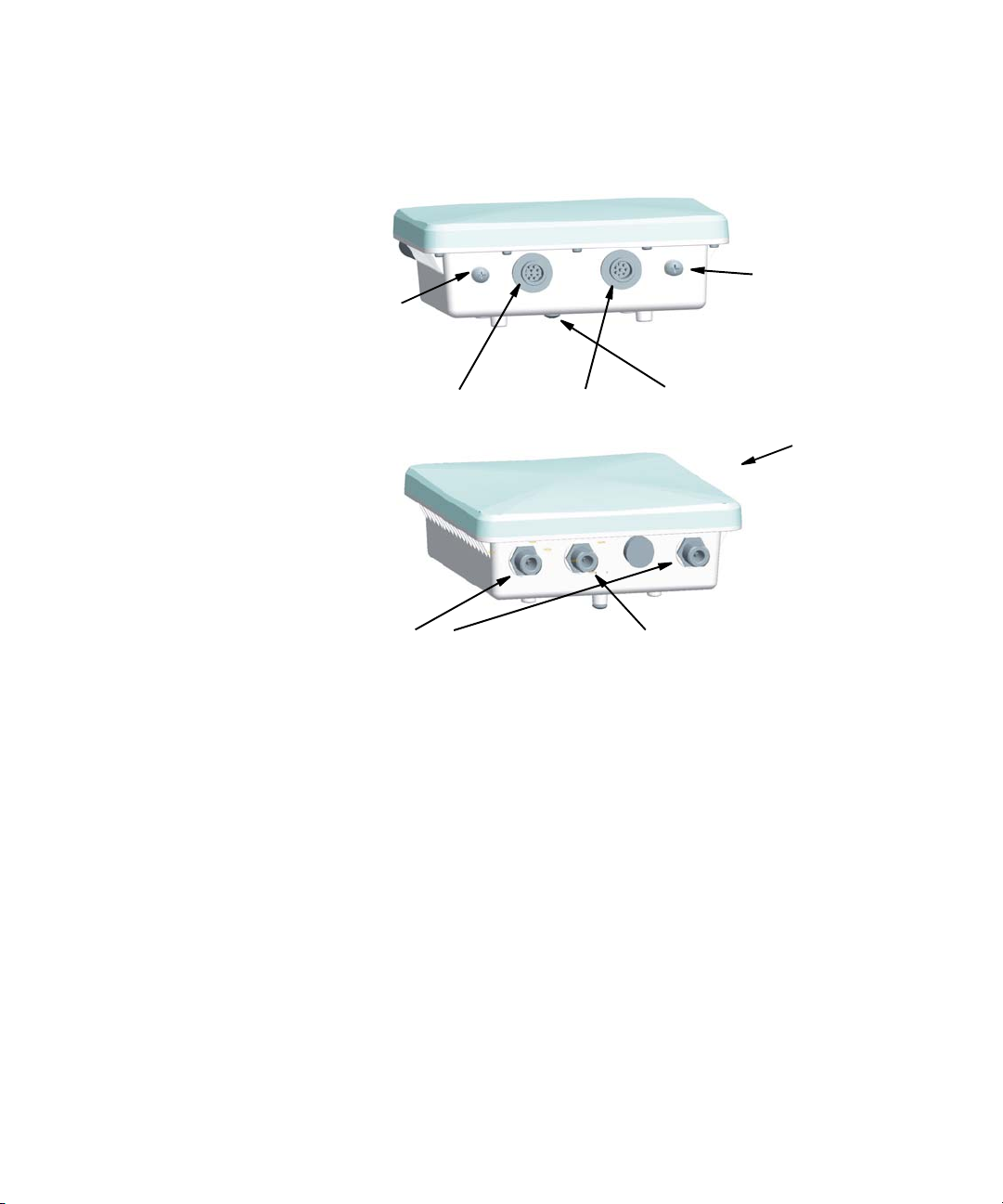
HARDWARE DESCRIPTION
Bottom
Console Port
Cap Attachment
Water Tight Test Point
(DO NOT REMOVE)
Console Port with
Protective Cap
Top View
N-Type External Antenna
Connector (2.4 GHz)
Ethernet/PoE
Connector
Grounding
Point
Integrated Antenna
N-Type External Antenna
Connector (5 GHz)
INTEGRATED HIGH-GAIN ANTENNA
The WL-575 bridge includes an integrated high-gain (17 dBi) flat-panel antenna
for 5 GHz operation. With this antenna, in a direct line-of-sight link using a
point-to-point deployment, the range can be as long as 15 km (9.3 miles), with a
6 Mbps data rate.
EXTERNAL ANTENNA OPTIONS
The WL-575 bridge also provides various external antenna options for both 5 GHz
and 2.4 GHz operation. In a point-to-multipoint configuration, an external
high-gain omnidirectional, sector, or high-gain panel antenna can be attached to
communicate with bridges spread over a wide area. The bridge requires a
2.4
GHz external antenna for 802.11b/g operation. The following table
summarizes the external antenna options:
1-4
Page 13

Item Antenna Type Gain (dBi) Horizontal
2.4 GHz 5.0 GHz
3CWE591 3Com 6/8 dBi Dual-Band Omni 6 8 360 5GHz: 20
3CWE596
3CWE598
* Half-power beam width
3Com 18/20 dBi Dual-Band Panel
3Com 8/10 dBi Dual-Band Panel
18 20 18 19
8 10 60 60
HPBW*
(Degrees)
Vertica l
HPBW*
(Degrees)
2.4GHz: 30
External antennas connect to the N-type RF connectors on the wireless bridge
using the optional RF coaxial cables.
Using the external antennas in a point-to-multipoint deployment, the maximum
range for bridge links are:
802.11b,g: 2.2 km
802.11a: 3 km
ETHERNET PORT
The wireless bridge has one 10BASE-T/100BASE-TX 8-pin DIN port that connects
to the power injector module using the included Ethernet cable. The Ethernet
port connection provides power to the wireless bridge as well as a data link to the
local network.
The wireless bridge appears as an Ethernet node and performs a bridging
function by moving packets from the wired LAN to the remote end of the wireless
bridge link.
NOTE: The power injector module does not support Power over Ethernet (PoE)
based on the IEEE 802.3af standard. The wireless bridge unit must always be
powered on by being connected to the power injector module.
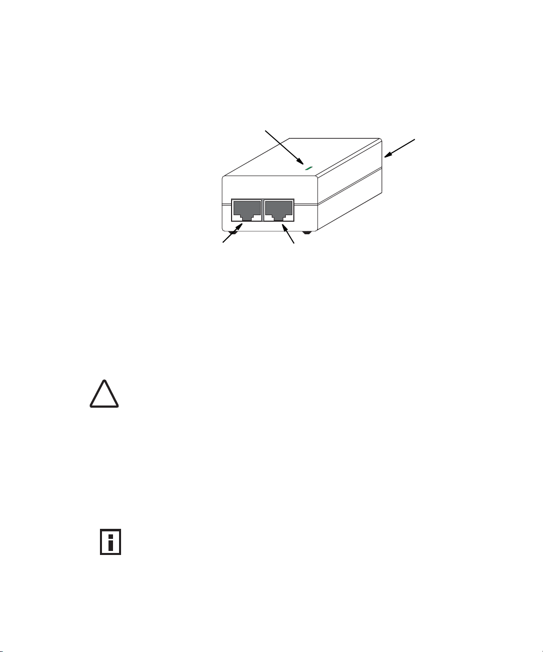
POWER INJECTOR MODULE
The wireless bridge receives power through its network cable connection using
power-over-Ethernet technology. A power injector module is included in the
wireless bridge package and provides two RJ-45 Ethernet ports, one for
connecting to the wireless bridge (Output), and the other for connecting to a
local LAN switch (Input).
The Input port uses an MDI (i.e., internal straight-through) pin configuration. You
can therefore use straight-through twisted-pair cable to connect this port to most
1-5
Page 14
network interconnection devices such as a switch or router that provide MDI-X
ports. However, when connecting the access point to a workstation or other
device that does not have MDI-X ports, you must use crossover twisted-pair cable.
LED Indicator
Input Output
Ethernet from Local
Network
Ethernet and Power
to Wireless Bridge
AC Power Socket
(Hidden)
The wireless bridge does not have a power switch. It is powered on when its
Ethernet port is connected to the power injector module, and the power injector
module is connected to an AC power source. The power injector includes one
LED indicator that turns on when AC power is applied.
The power injector module automatically adjusts to any AC voltage between
100-240 volts at 50 or 60 Hz. No voltage range settings are required.
WARNING: The power injector module is designed for indoor use only. Never mount
the power injector outside with the wireless bridge unit.
!
GROUNDING POINT
Even though the wireless bridge includes its own built-in lightning protection, it is
important that the unit is properly connected to ground. A grounding screw is
provided for attaching a ground wire to the unit.
WATER TIGHT TEST POINT
CAUTION: Do not remove or loosen this screw. Doing so could lead to damage
of the unit.
1-6
Page 15
WALL- AND POLE-MOUNTING BRACKET KIT
The wireless bridge includes a bracket kit that can be used to mount the bridge to
a wall, pole, radio mast, or part of a tower structure.
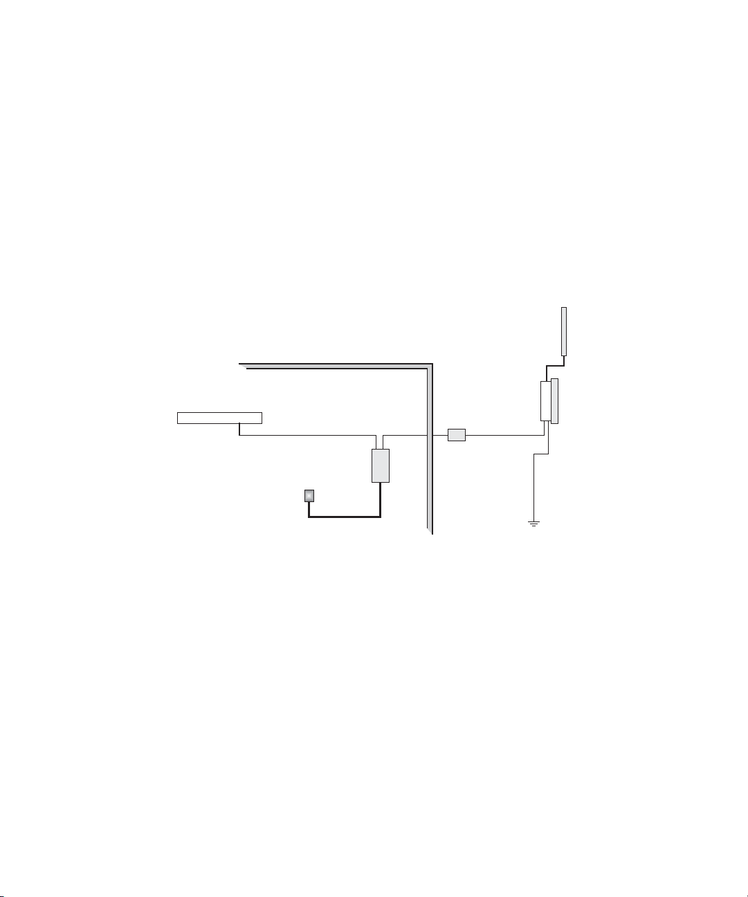
SYSTEM CONFIGURATION
At each location where a unit is installed, it must be connected to the local
network using the power injector module. The following figure illustrates the
system component connections.
External Antenna
LAN Switch
OPERATING MODES
The 3Com Outdoor 11a Building to Building Bridge and 11bg Access Point system
provides access point or bridging services through either the 5 GHz or 2.4 GHz
radio interfaces.
The unit supports both point-to-point and point-to-multipoint bridge modes.
Wireless bridge units can be used as regular 802.11a/b/g access points connected
to a local wired LAN, providing connectivity and roaming services for wireless
clients in an outdoor area. Units can also be used purely as bridges connecting
remote LANs. Alternatively, you can employ both access point and bridging
functions together, offering a flexible and convenient wireless solution for many
applications.
Ethernet Cable
AC Power
Indoor Outdoor
Power
Injector
RF Coaxial Cable
Wireless Bridge Unit
Ethernet
Cable
Lightning
Arrestor
Ground Wire
1-7
Page 16
The wireless bridge modes connect two or more wired networks, for example
networks in different buildings with no wired connections. You will need a 3Com
Outdoor 11a Building to Building Bridge and 11bg Access Point unit on both
sides of the connection. The wireless bridge can connect up to six remote
networks.
When using bridge mode on a radio band, only wireless bridge units can
associate to each other. Wireless clients can only associate with the unit using a
radio band set to access point mode.
POINT-TO-POINT CONFIGURATION
Two bridges can form a wireless point-to-point link using their 5 GHz (802.11a)
integrated antennas. A point-to-point configuration can provide a limited data
rate (6 Mbps) link over a long range (up to 15.4 km), or a high data rate (108
Mbps) over a short range (1.3 km).
POINT-TO-MULTIPOINT CONFIGURATION
A wireless bridge set to “Master” mode can use an omnidirectional antenna to
connect to as many as six bridges in a point-to-multipoint configuration. There
can only be one “Master” unit in the wireless bridge network, all other bridges
must be set as “Slave” units.
The following figure shows a point-to-multipoint “star” configuration with one
bridge set to “Master” and using an omnidirectional antenna.
1-8
Page 17
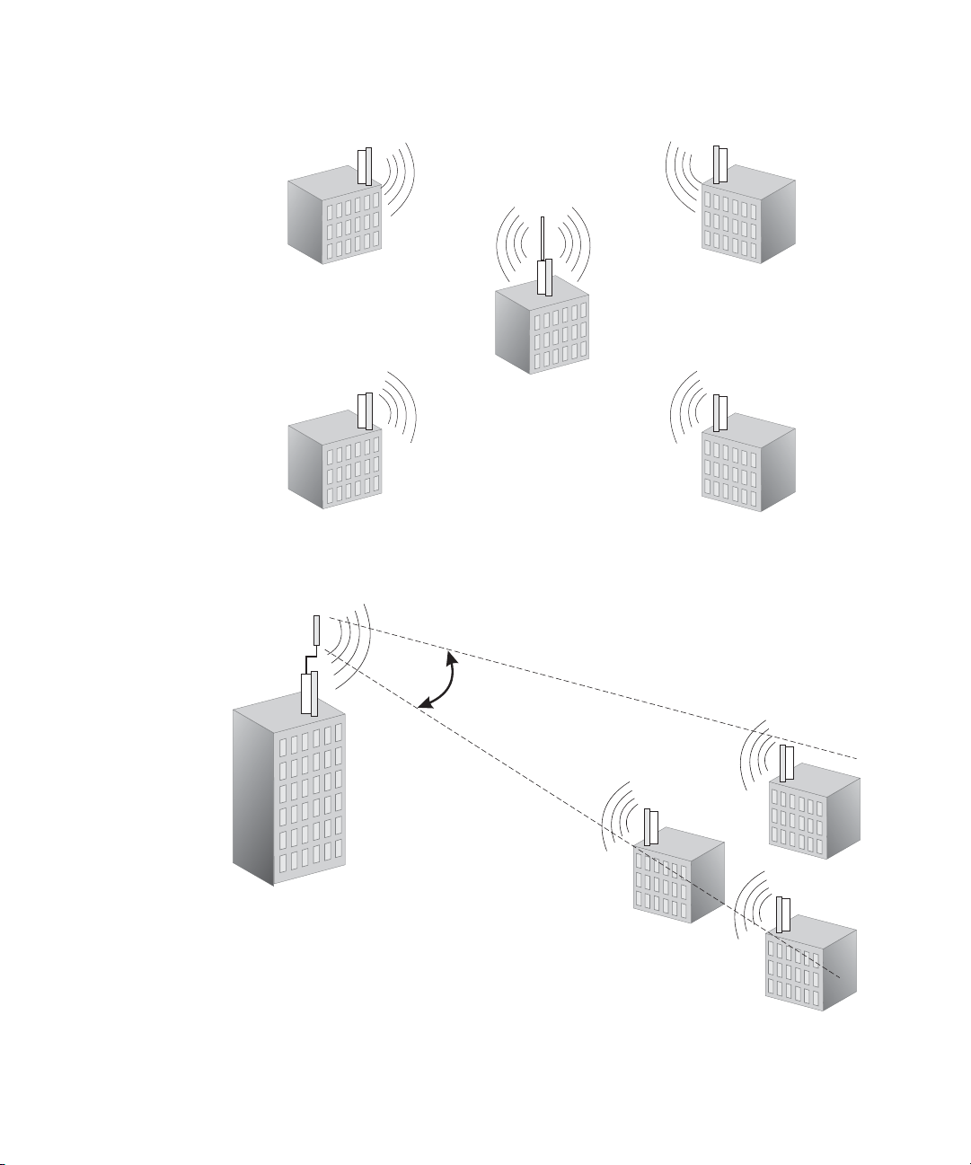
The following figure shows a point-to-multipoint “in-line” configuration with one
bridge set to “Master” and using a directional panel antenna.
19° Beam
Angle
1-9
Page 18

1-10
Page 19

2 BRIDGE LINK PLANNING
The 3Com Outdoor 11a Building to Building Bridge and 11bg Access Point
supports fixed point-to-point or point-to-multipoint wireless links. A single link
between two points can be used to connect a remote site to larger core network.
Multiple bridge links can provide a way to connect widespread Ethernet LANs.
For each link in a wireless bridge network to be reliable and provide optimum
performance, some careful site planning is required. This chapter provides
guidance and information for planning your wireless bridge links.
NOTE: The planning and installation of the wireless bridge requires professional
personnel that are trained in the installation of radio transmitting equipment.
The user is responsible for compliance with local regulations concerning items
such as antenna power, use of lightning arrestors, grounding, and radio mast or
tower construction. Therefore, it is recommended to consult a professional
contractor knowledgeable in local radio regulations prior to equipment
installation.
2-1
Page 20

DATA RATES
Using the 5.0 GHz integrated antenna, two WL-575 bridges can operate over a
range of up to 15.4 km (9.6 miles) or provide a high-speed connection of
54
Mbps (108 Mbps in turbo mode). However, the maximum data rate for a link
decreases as the operating range increases. A 15.4 km link can only operate up to
6 Mbps, whereas a 108 Mbps connection is limited to a range of 1.3 km.
When you are planning each wireless bridge link, take into account the maximum
distance and data rates for the various antenna options. A summary for 5.0 GHz
(802.11a) antennas is provided in the following table.
.
Distances Achieved Using 17 dBi Integrated Antennas
Data Rate Distance
6 Mbps 15.4 km
9 Mbps 14.7 km
12 Mbps 14 km
18 Mbps 12.8 km
24 Mbps 11.1 km
36 Mbps 6.5 km
48 Mbps 2.9 km
54 Mbps 1.8 km
12 Mbps Turbo 13.4 km
18 Mbps Turbo 12.8 km
24 Mbps Turbo 12.2 km
36 Mbps Turbo 11.1 km
48 Mbps Turbo 8.2 km
72 Mbps Turbo 4.6 km
96 Mbps Turbo 2.1 km
108 Mbps Turbo 1.3 km
Distances provided in this table are an estimate for a typical
deployment and may be reduced by local regulatory limits.
For accurate distances, you need to calculate the power link
budget for your specific environment.
2-2
Page 21

RADIO PATH PLANNING
Although the wireless bridge uses IEEE 802.11a radio technology, which is
capable of reducing the effect of multipath signals due to obstructions, the
wireless bridge link requires a “radio line-of-sight” between the two antennas for
optimum performance.
The concept of radio line-of-sight involves the area along a radio link path
through which the bulk of the radio signal power travels. This area is known as
the first Fresnel Zone of the radio link. For a radio link not to be affected by
obstacles along its path, no object, including the ground, must intrude within
60% of the first Fresnel Zone.
The following figure illustrates the concept of a good radio line-of-sight.
Visual Line of Sight
If there are obstacles in the radio path, there may still be a radio link but the
quality and strength of the signal will be affected. Calculating the maximum
clearance from objects on a path is important as it directly affects the decision on
antenna placement and height. It is especially critical for long-distance links,
where the radio signal could easily be lost.
When planning the radio path for a wireless bridge link, consider these factors:
• Avoid any partial line-of-sight between the antennas.
• Be cautious of trees or other foliage that may be near the path, or may grow
and obstruct the path.
Radio Line of Sight
2-3
Page 22

• Be sure there is enough clearance from buildings and that no building
construction may eventually block the path.
• Check the topology of the land between the antennas using topographical
maps, aerial photos, or even satellite image data (software packages are
available that may include this information for your area)
• Avoid a path that may incur temporary blockage due to the movement of
cars, trains, or aircraft.
ANTENNA HEIGHT
A reliable wireless link is usually best achieved by mounting the antennas at each
end high enough for a clear radio line of sight between them. The minimum
height required depends on the distance of the link, obstacles that may be in the
path, topology of the terrain, and the curvature of the earth (for links over 3
miles).
For long-distance links, a mast or pole may need to be constructed to attain the
minimum required height. Use the following table to estimate the required
minimum clearance above the ground or path obstruction (for 5.0 GHz bridge
links).
.
Max Clearance
Total Link
Distance
0.25 mile (402 m) 4.5 ft (1.4 m) 0 4.5 ft (1.4 m)
0.5 mile (805 m) 6.4 ft (1.95 m) 0 6.4 ft (1.95 m)
1 mile (1.6 km) 9 ft (2.7 m) 0 9 ft (2.7 m)
2 miles (3.2 km) 12.7 ft (3.9 m) 0 12.7 ft (3.9 m)
3 miles (4.8 km) 15.6 ft (4.8 m) 1.8 ft (0.5 m) 17.4 ft (5.3 m)
4 miles (6.4 km) 18 ft (5.5 m) 3.2 ft (1.0 m) 21.2 ft (6.5 m)
5 miles (8 km) 20 ft (6.1 m) 5 ft (1.5 m) 25 ft (7.6 m)
7 miles (11.3 km) 24 ft (7.3 m) 9.8 ft (3.0 m) 33.8 ft (10.3 m)
9 miles (14.5 km) 27 ft (8.2 m) 16 ft (4.9 m) 43 ft (13.1 m)
12 miles (19.3 km) 31 ft (9.5 m) 29 ft (8.8 m) 60 ft (18.3 m)
15 miles (24.1 km) 35 ft (10.7 m) 45 ft (13.7 m) 80 ft (24.4 m)
17 miles (27.4 km) 37 ft (11.3 m) 58 ft (17.7 m) 95 ft (29 m)
for 60% of First
Fresnel Zone at
5.8 GHz
2-4
Approximate
Clearance for
Earth Curvature
Total Clearance
Required at
Mid-point of
Link
Page 23
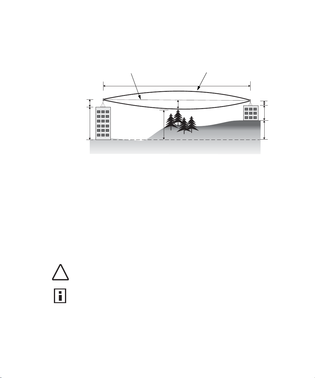
Note that to avoid any obstruction along the path, the height of the object must
be added to the minimum clearance required for a clear radio line-of-sight.
Consider the following simple example, illustrated in the figure below.
Radio Line of Sight
5.4 m
B
1.4 m
9m
12 m
2.4 m
20 m
Visual Line of Sight
3 miles (4.8 km)
A
17 m
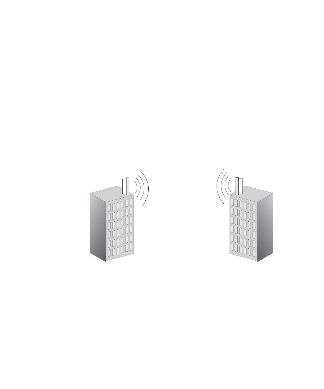
A wireless bridge link is deployed to connect building A to a building B, which is
located three miles (4.8 km) away. Mid-way between the two buildings is a small
tree-covered hill. From the above table it can be seen that for a three-mile link,
the object clearance required at the mid-point is 5.3 m (17.4 ft). The tree-tops on
the hill are at an elevation of 17 m (56 ft), so the antennas at each end of the link
need to be at least 22.3 m (73 ft) high. Building A is six stories high, or 20 m (66
ft), so a 2.3 m (7.5
ft) mast or pole must be constructed on its roof to achieve the
required antenna height. Building B is only three stories high, or 9 m (30 ft), but is
located at an elevation that is 12 m (39 ft) higher than building A. To mount an
antenna at the required height on building B, a mast or pole of only 1.3 m (4.3 ft)
is needed.
WARNING: Never construct a radio mast, pole, or tower near overhead power
lines.
!
NOTE: Local regulations may limit or prevent construction of a high radio mast
or tower. If your wireless bridge link requires a high radio mast or tower, consult
a professional contractor for advice.
2-5
Page 24
ANTENNA POSITION AND ORIENTATION
Once the required antenna height has been determined, other factors affecting
the precise position of the wireless bridge must be considered:
• Be sure there are no other radio antennas within 2 m (6 ft) of the wireless
bridge
• Place the wireless bridge away from power and telephone lines
• Avoid placing the wireless bridge too close to any metallic reflective surfaces,
such as roof-installed air-conditioning equipment, tinted windows, wire
fences, or water pipes
• The wireless bridge antennas at both ends of the link must be positioned
with the same polarization direction, either horizontal or vertical
Antenna Polarization — The wireless bridge’s integrated antenna sends a radio
signal that is polarized in a particular direction. The antenna’s receive sensitivity is
also higher for radio signals that have the same polarization. To maximize the
performance of the wireless link, both antennas must be set to the same
polarization direction. Ideally the antennas should be pointing upwards mounted
on the top part of a pole.
2-6
Page 25

RADIO INTERFERENCE
The avoidance of radio interference is an important part of wireless link planning.
Interference is caused by other radio transmissions using the same or an adjacent
channel frequency. You should first scan your proposed site using a spectrum
analyzer to determine if there are any strong radio signals using the 802.11a
channel frequencies. Always use a channel frequency that is furthest away from
another signal.
If radio interference is still a problem with your wireless bridge link, changing the
antenna polarization direction may improve the situation.
NOTE: For US operation of 5 GHz WDS links, avoid possible radio link disruption
from radar by selecting the following recommended RF channels -- Normal
mode: 49, 153, 157, 161, 165, Turbo mode: 42, 152, 160.
WEATHER CONDITIONS
When planning wireless bridge links, you must take into account any extreme
weather conditions that are known to affect your location. Consider these
factors:
• Te mp e ra tu re — The wireless bridge is tested for normal operation in
temperatures from -40°C to 60°C. Operating in temperatures outside of this
range may cause the unit to fail.
• Wind Velocity — The wireless bridge can operate in winds up to 100 MPH
and survive higher wind speeds up to 150 MPH. You must consider the
known maximum wind velocity and direction at the site and be sure that any
supporting structure, such as a pole, mast, or tower, is built to withstand this
force.
• Lightning — The wireless bridge includes its own built-in lightning
protection. However, you should make sure that the unit, any supporting
structure, and cables are all properly grounded. Additional protection using
lightning rods, lightning arrestors, or surge suppressors may also be
employed.
• Rain — The wireless bridge is weatherproofed against rain. Also, prolonged
heavy rain has no significant effect on the radio signal. However, it is
recommended to apply weatherproof sealing tape around the Ethernet port
and antenna connectors for extra protection. If moisture enters a connector,
it may cause a degradation in performance or even a complete failure of the
link.
2-7
Page 26

• Snow and Ice — Falling snow, like rain, has no significant effect on the
radio signal. However, a build up of snow or ice on antennas may cause the
link to fail. In this case, the snow or ice has to be cleared from the antennas
to restore operation of the link.
ETHERNET CABLING
When a suitable antenna location has been determined, you must plan a cable
route form the wireless bridge outdoors to the power injector module indoors.
Consider these points:
• The Ethernet cable length should never be longer than 100 m (328 ft)
• Determine a building entry point for the cable
• Determine if conduits, bracing, or other structures are required for safety or
protection of the cable
• For lightning protection at the power injector end of the cable, use a
lightning arrestor immediately before the Ethernet cable enters the building
GROUNDING
It is important that the wireless bridge, cables, and any supporting structures are
properly grounded. The wireless bridge unit includes a grounding screw for
attaching a ground wire. Be sure that grounding is available and that it meets
local and national electrical codes.
2-8
Page 27

3 HARDWARE INSTALLATION
Before mounting antennas to set up your wireless bridge links, be sure you have
selected appropriate locations for each antenna. Follow the guidance and
information in Chapter 2, “Wireless Link Planning.”
Also, before mounting units in their intended locations, you should first perform
initial configuration and test the basic operation of the wireless bridge links in a
controlled environment over a very short range. (See the section “Testing Basic
Link Operation” in this chapter.)
The wireless bridge includes its own bracket kit for mounting the unit to a 1.5 to
2
inch diameter steel pole or tube. The pole-mounting bracket allows the unit to
be mounted to part of a radio mast or tower structure. The unit also has a
wall-mounting bracket kit that enables it to be fixed to a building wall or roof
when using external antennas.
Hardware installation of the wireless bridge involves these steps:
1 Mount the unit on a wall, pole, mast, or tower using the mounting bracket.
2 Mount external antennas on the same supporting structure as the bridge and
connect them to the bridge unit.
3 Connect the Ethernet cable and a grounding wire to the unit.
4 Connect the power injector to the Ethernet cable, a local LAN switch, and an
AC power source.
5 Align antennas at both ends of the link.
3-1
Page 28
TESTING BASIC LINK OPERATION
Set up the units over a very short range (15 to 25 feet), either outdoors or
indoors. Connect the units as indicated in this chapter and be sure to perform all
the basic configuration tasks outlined in Chapter 4, “Initial Configuration.” When
you are satisfied that the links are operating correctly, proceed to mount the units
in their intended locations.
MOUNT THE UNIT
The bridge can be mounted on the following types of surfaces:
Pole
Wall
CAUTION: The bridge is intended for outdoor use only. Do not install the bridge
indoors.
!
USING THE POLE-MOUNTING BRACKET
Perform the following steps to mount the unit to a 1.5 to 2 inch diameter steel
pole or tube using the mounting bracket:
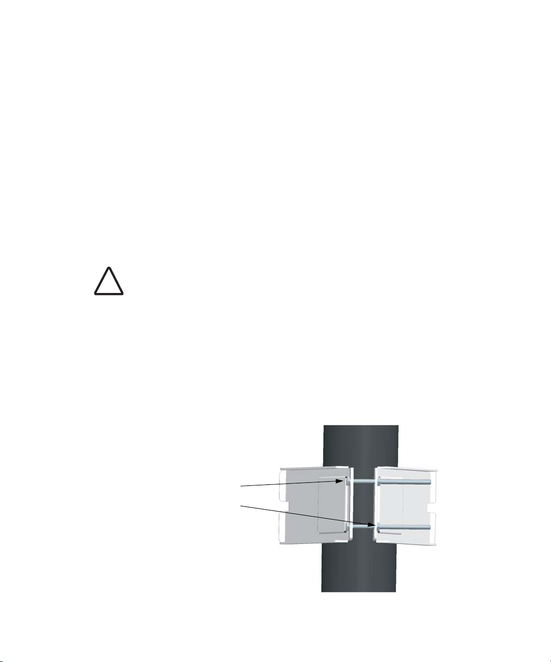
1 Place the V-shaped part of the bracket around the pole and tighten the
securing nuts just enough to hold the bracket to the pole. (The bracket may
need to be rotated around the pole during the antenna alignment process.)
Attach V-shaped
parts to pole with
provided nuts and
bolts
3-2
Page 29
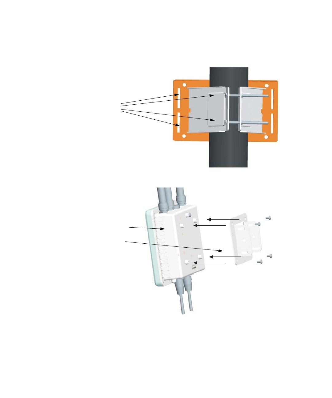
2 Fit the edges of the V-shaped part into the slots in the rectangular plate, and
tighten the nuts.
Fit the edges of
the V-shaped
part into the slots
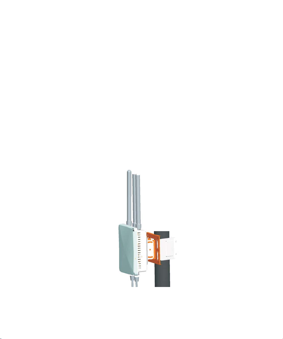
3 Attach the adjustable rectangular plate to the bridge with supplied screws.
Attach the
adjustable
rectangular plate
to the bridge
3-3
Page 30
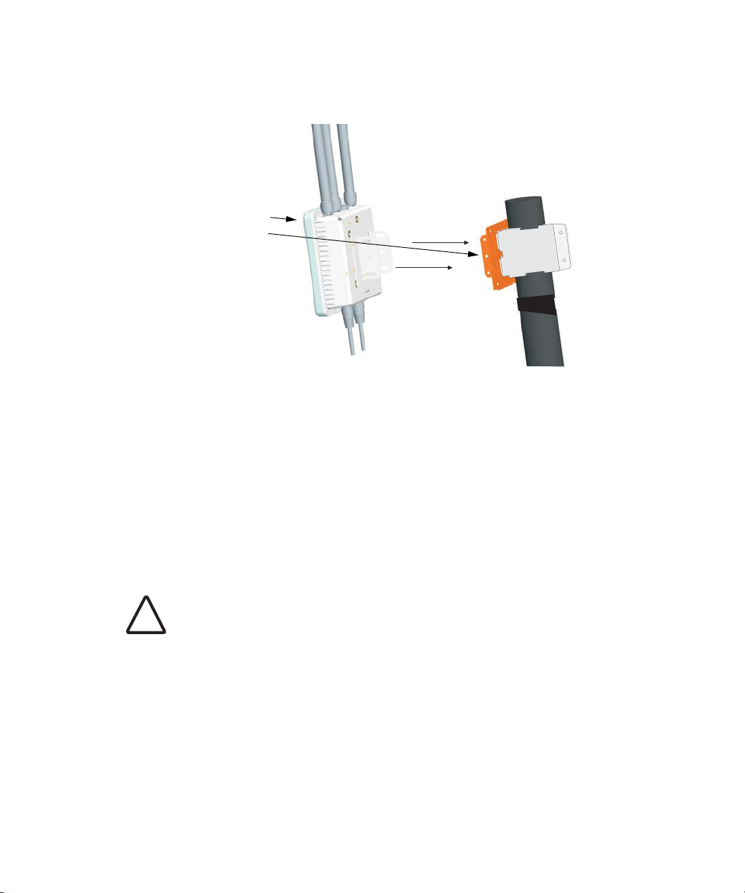
4 Attach the bridge with bracket to the plate already fixed to the pole.
Attach the bridge
to the plate on
the pole
5 Use the included nuts to secure the wireless bridge to the pole bracket. Note
that the wireless bridge tilt angle may need to be adjusted during the
antenna alignment process.
Be sure to take account of the antenna polarization direction; all antennas in
a link must be mounted with the same polarization.
USING THE WALL-MOUNTING BRACKET
Perform the following steps to mount the unit to a wall using the wall-mounting
bracket:
CAUTION: The wall-mounting bracket does not allow the wireless bridge’s
intrgrated antenna to be aligned. It is intended for use with the unit using an
!
external antenna.
3-4
Page 31

1 Always attach the bracket to a wall with flat side flush against the wall (see
following figure).
2 Position the bracket in the intended location and mark the position of the
four mounting screw holes.
3 Drill four holes in the wall that match the screws and wall plugs included in
the bracket kit, then secure the bracket to the wall.
4 Use the included nuts to tightly secure the wireless bridge to the bracket.
3-5
Page 32

CONNECT EXTERNAL ANTENNAS
The bridge’s primary antenna is it’s built-in internal antenna. For some
applications when deploying an WL-575 unit for a bridge link or access point
operation, you may need to mount external antennas and connect them to the
bridge. Typically, a bridge link requires a 5.0 GHz antenna, and access point
operation a 2.4
an external antenna for 2.4 GHz operation.
Perform these steps:
1 Mount the external antenna to the same supporting structure as the bridge,
within 3 m (10 ft) distance, using the bracket supplied in the antenna
package.
2 Connect the antenna to the bridge’s N-type connector using the RF coaxial
cable provided in the antenna package.
3 Apply weatherproofing tape to the antenna connectors to help prevent water
entering the connectors.
GHz antenna. WL-575 units acting as managed APs also require
2.4 GHz
N-type Connector
5 GHz
N-type Connector
2.4 GHz
N-type Connector
RF Coaxial Cable
5 GHz External
High-gain Panel
Antenna
2.4 GHz External
Omnidirectional
Antenna
3-6
Page 33

CONNECT CABLES TO THE UNIT
WARNING: Do not connect or disconnect cables or otherwise work with the
bridge during periods of lightning activity.
!
1 Attach the Ethernet cable to the Ethernet port on the wireless bridge.
2 For extra protection against rain or moisture, apply weatherproofing tape (not
included) around the Ethernet connector.
3 Be sure to ground the unit with an appropriate grounding wire (not included)
by attaching it to the grounding screw on the unit.
4 Be sure to install a lightning arrestor on the Ethernet cable between the
bridge and power injector. The lightning arrestor should be placed outdoors,
immediately before the Ethernet cable enters the building.
CAUTION: Be sure that grounding is available and that it meets local and national
electrical codes.
!
PoE (Ethernet) PortConsole Port
Grounding Screw
Ethernet Cable
CONNECT THE POWER INJECTOR
To connect the wireless bridge to a power source:
CAUTION: Do not install the power injector outdoors. The unit is for indoor
installation only.
!
3-7
Ground Wire
Page 34

NOTE: The wireless bridge’s Ethernet port does not support Power over Ethernet
(PoE) based on the IEEE 802.3af standard. Do not try to power the unit by
connecting it directly to a network switch that provides IEEE 802.3af PoE. Always
connect the unit to the included power injector module.
1 Connect the Ethernet cable from the wireless bridge to the RJ-45 port labeled
“Output” on the power injector.
2 Connect a straight-through unshielded twisted-pair (UTP) cable from a local
LAN switch to the RJ-45 port labeled “Input” on the power injector. Use
Category 5e or better UTP cable for 10/100BASE-TX connections.
NOTE: The RJ-45 port on the power injector is an MDI port. If connecting
directly to a computer for testing the link, use a crossover cable.
AC power
Ethernet cable
from LAN Switch
Input
Input
Output
Output
Ethernet cable to
wireless bridge
Power LED indicator
1 Insert the power cable plug directly into the standard AC receptacle on the
power injector.
2 Plug the other end of the power cable into a grounded, 3-pin socket, AC
power source.
NOTE: For International use, you may need to change the AC line cord. You
must use a line cord set that has been approved for the receptacle type in your
country.
3 Check the LED on top of the power injector to be sure that power is being
supplied to the wireless bridge through the Ethernet connection.
3-8
Page 35

CHECK THE LED INDICATORS
The bridge’s 11a and 11b/g LEDs operate in two display modes, which are
configurable through the software. The default AP mode indicates data traffic
rates. The RSSI mode indicates the received signal power and is for use when
aligning antennas in a bridge link.
When the bridge is connected to power, the LEDs indicate as follows:
LED Color Indicates
11b/g
11a
|||||||||||||||||
Power Green The bridge is powered up and operating
normally.
Powe r
Link
Off The bridge is not receiving power or
there is a fault with the power supply.
Amber The system is under cold reset status.
Link Green The bridge has a 10/100 Mbps Fast
Ethernet connection, but there is no
activity.
Flashing Indicates that the bridge is transmitting
or receiving data on a 10/100 Mbps
Ethernet LAN. Flashing rate is
proportional to network activity.
Off No link is present or the Ethernet LAN
port is disabled.
11a
(Three
LEDs)
Green
and
Flashing
The 802.11a 5.3 GHz radio is enabled.
RSSI Mode:
One fully lit LED indicates a low RSSI
output level, two LEDs.a medium
level, and three LEDs the maximum
level.
A flashing LED indicates an
intermediate RSSI output level
AP Mode:
One fully lit LED indicates a low
traffic rate, two LEDs.a medium rate,
and three LEDs the maximum rate.
A flashing LED indicates an
intermediate traffic rate level
Off No link is present or the 802.11a radio is
disabled.
3-9
Page 36

LED Color Indicates
ALIGN ANTENNAS
After wireless bridge units have been mounted, connected, and their radios are
operating, bridge link antennas must be accurately aligned to ensure optimum
performance. This alignment process is particularly important for long-range
point-to-point links. In a point-to-multipoint configuration the root bridge uses an
omnidirectional or sector antenna, which does not require alignment, but bridge
nodes still need to be correctly aligned with the root bridge antenna.
Point-to-Point Configurations – In a point-to-point configuration, the
alignment process requires two people, one at each end of the link. The use of
cell phones or two-way radio communication may help with coordination. To
start, you can just point the antennas at each other, using binoculars or a
compass to set the general direction. For accurate alignment, you must
monitor the signal strength LEDs as the antenna moves horizontally and
vertically.
Point-to-Multipoint Configurations – In a point-to-multipoint
configuration all bridge nodes must be aligned with the root bridge antenna.
The alignment process is the same as in point-to-point links, but only the
bridge node end of the link requires the alignment.
11g
(Three
LEDs)
Amber
and
Flashing
Off No link is present or the 802.11g radio
The 802.11g 2.4 GHz radio is enabled.
RSSI Mode:
One fully lit LED indicates a low RSSI
output level, two LEDs.a medium
level, and three LEDs the maximum
level.
A flashing LED indicates an
intermediate RSSI output level
AP Mode:
One fully lit LED indicates a low
traffic rate, two LEDs.a medium rate,
and three LEDs the maximum rate.
A flashing LED indicates an
intermediate traffic rate level
is disabled.
The signal strength LEDs indicate the received radio signal strength for a particular
bridge link. The more LEDs that turn on, the stronger the signal. Alternatively, you
can monitor the Receive Signal Strength Indicator (RSSI) value directly from the
management interface. The higher the RSSI value, the stronger the signal.
3-10
Page 37

When you move the antenna during alignment, the radio signal from the remote
antenna can be seen to have a strong central main lobe and smaller side lobes.
The object of the alignment process is to set the antenna so that it is receiving the
strongest signal from the central main lobe.
Vertical Scan
Remote
Antenna
Horizontal Scan
RSSI
Voltage
Main Lobe
Maximum
Maximum Signal Strength Position
for Horizontal Alignment
RSSI Voltage
Side Lobe
Maximum
Maximum Signal
Strength Position for
Vertical Alignment
To align the antennas in the link, monitor the signal strength LEDs or the RSSI
value in the management interface. Start with one antenna fixed and then
perform the following procedure on the other antenna:
NOTE: The RSSI output can be configured through management interfaces to
output a value for specific WDS ports. See page
High 11a Signal
6-40 for more information.
11b/g
11a
Power
Link
Medium 11a Signal
Low 11a Signal
3-11
11b/g
11a
11b/g
11a
Power
Link
Power
Link
Page 38

1 Pan the antenna horizontally back and forth while checking the LEDs. If using
the pole-mounting bracket with the unit, you must rotate the mounting
bracket around the pole. Other external antenna brackets may require a
different horizontal adjustment.
2 Find the point where the signal is strongest (all LEDs on) and secure the
horizontal adjustment in that position.
NOTE: Sometimes there may not be a central lobe peak in the voltage because
vertical alignment is too far off; only two similar peaks for the side lobes are
detected. In this case, fix the antenna so that it is halfway between the two
peaks.
3 Loosen the vertical adjustment on the mounting bracket and tilt the antenna
slowly up and down while checking the LEDs.
4 Find the point where the signal is strongest and secure the vertical adjustment
in that position.
3-12
Page 39

4 INITIAL CONFIGURATION
The 3Com Outdoor 11a Building to Building Bridge and 11bg Access Point offers
a variety of management options, including a web-based interface.
The initial configuration steps can be made through the web browser interface.
The access point requests an IP address via DHCP by default. If no response is
received from the DHCP server, then the access point uses the default address
169.254.2.1.
If the default AP configuration does not meet your network requirements, or if
you want to customize the settings for your own network, you can use these
tools to change the configuration:
1 Launch the 3Com Wireless Infrastructure Device Manager (Widman) utility
2 Directly connect to the device through it’s Ethernet port or console port
NETWORKS WITH A DHCP SERVER
If your network has a DHCP server, an IP address is automatically assigned to the
AP. It takes between one and two minutes for the Access Point to determine if
there is a DHCP server on the network. Use the 3Com Wireless Infrastructure
Device Manager (Widman) included on the 3Com Installation CD to locate the
Access Point on the network and view its IP address. After you determine the AP’s
IP address, you can enter that IP address into a web browser on a computer on
the same subnet to view the Access Point’s system status or change its
configuration.
NETWORKS WITHOUT A DHCP SERVER
If your network does not have a DHCP server, the Access Point uses a factory
assigned IP address (169.254.2.1). You can use that IP address to configure the
Access Point, or you can assign a new IP address to the Access Point. To verify that
the Access Point is using the default IP address assigned at the factory:
4-1
Page 40

CHAPTER 4: INITIAL CONFIGURATION
1 Connect a computer directly to the Access Point using the supplied standard
Category 5 UTP Ethernet cable.
2 Enter the Access Point’s default IP address (169.254.2.1) into the computer’s
web browser. If the Configuration Management System starts, the Access
Point is using the factory assigned IP address. You can configure the Access
Point with the following login information:
Login name: admin
Password: password
If the Configuration Management System does not start, the Access Point is
on a different subnet than the computer. Install and start the 3Com Wireless
Infrastructure Device Manager to discover the Access Point’s IP address.
USING THE 3COM INSTALLATION CD
The 3Com Installation CD contains the following tools and utilities: 3Com
Wireless Infrastructure Device Manager-an administration tool that helps you
select 3Com wireless LAN devices and launch their configurations in your Web
browser.
LAUNCH THE 3COM WIRELESS INFRASTRUCTURE DEVICE
M
ANAGER (WIDMAN) UTILITY
1 Turn on the computer.
2 Insert the 3Com Installation CD into the CD-ROM drive.
The CD will Autorun. If it does not Autorun, you can start the setup menu
from the Windows Start menu. For example: Start > Run > d: setup.exe.
3 In the menu, click Tools and Utilities.
4 In the next screen, click the software you want to install.
5 Follow the on screen instructions to complete the installation.
Reboot the computer if prompted to do so.
LAUNCHING THE 3COM WIRELESS INTERFACE DEVICE MANAGER
To be able to configure the Access Point you need to run the Wireless Interface
Device Manager. Go to Start > Programs > 3Com Wireless > Wireless
Interface Device Manager.
If the device is working correctly the following screen should be seen.
4-2
Page 41

Figure 1 Wireless Interface Device Manager
Click on the Properties button to see the following screen
Figure 2 Wireless Interface Device Manager - Properties
4-3
Page 42

CHAPTER 4: INITIAL CONFIGURATION
Directly connect to the device through its Ethernet port or console port.
Follow the instructions below to login into the AP Configuration screen:
1 Load a web browser and enter <http://169.254.2.1>.
2 The Logon screen appears.
To log on to the Web interface:
1 Username, type admin (case sensitive).
2 Password, type password
3 Click Log On.
FIRST TIME ONLY
When you log in for the first time, you may be asked to select your country.
Choose your country from the drop-down list and then click Apply.
Click on the Setup Wizard for initial configuration.
For a new access point installation, the default WLAN Service Area (ESSID) is
3Com and no security is set. Unless it detects a DHCP server on the network, the
access point uses Auto IP to assign an IP address of the form 169.254.2.1.
Use the 3Com Wireless Infrastructure Device Manager to locate 3Com Wireless
LAN devices and launch their configurations. When installing the device manager,
make sure the computer is connected to the same network as the device to be
configured. After installing and launching the device manager, select the device
to be configured from network tree and click Configure to launch the
configuration Web interface.
USING THE SETUP WIZARD
There are only a few basic steps you need to complete to connect the access
point to your corporate network and provide network access to wireless clients.
The Setup Wizard takes you through configuration procedures for the wireless
Service Set Identifier, the radio channel selection, IP configuration and basic
authentication for wireless clients.
The access point can be managed by any computer using a web browser (such as
Internet Explorer 5.0 or above). Enter the default IP address: http://169.254.2.1.
4-4
Page 43

Using the Setup Wizard
NOTE: If you changed the default IP address via the command line interface above,
use that address instead of the one shown here.
Logging In – Enter the username “admin,” and password “password,” then
click LOGIN. For information on configuring a user name and password, see
page
23.
Figure 3 Login Page
4-5
Page 44

CHAPTER 4: INITIAL CONFIGURATION
The home page displays the Main Menu.
Figure 4 Home Page
Launching the Setup Wizard – To perform initial configuration, click Setup
Wizard on the home page, select the VAP you wish to configure, then click on the
[Next] button to start the process.
Figure 5 Setup Wizard - Start
1 Service Set ID – Enter the service set identifier in the SSID box which all
wireless clients must use to associate with the access point. The SSID is case
sensitive and can consist of up to 32 alphanumeric characters.
4-6
Page 45

Using the Setup Wizard
Figure 6 Setup Wizard - Step 1
2 Radio Channel – You must enable radio communications for 802.11a and
802.11b/g, and set the operating radio channel.
NOTE: Available channel settings are limited by local regulations, which determine
the channels that are available. This User Guide shows channels and settings that
apply to North America (United States and Canada), with 13 channels available for
the 802.11a interface and 11 channels for the 802.11g interface. Other regions my
have different channels and settings available.
Figure 7 Setup Wizard - Step 2
4-7
Page 46

CHAPTER 4: INITIAL CONFIGURATION
802.11a
Turbo Mode – If you select Enable, the access point will operate
in turbo mode with a data rate of up to 108 Mbps. Normal
mode support 13 channels, Turbo mode supports only 5
channels. (Default: Disabled)
802.11a Radio Channel – Set the operating radio channel
number. (Default: 60ch, 5.300
Auto Channel Select – Select Enable for automatic radio
channel detection. (Default: Enabled)
802.11b/g
Turbo Mode - If you select Enable, the access point will operate in
turbo mode with a data rate of up to 108 Mbps. Normal mode support
11 channels, Turbo mode supports only 1 channel. (Default: Disabled)
802.11g Radio Channel - Set the operating radio channel number.
(Range 1-11; Default: 1)
3 IP Configuration – Either enable or disable Dynamic Host
Configuration Protocol (DHCP) for automatic IP configuration. If you
disable DHCP, then manually enter the IP address and subnet mask. If
a management station exists on another network segment, then you must
enter the IP address for a gateway that can route traffic between these
segments. Then enter the IP address for the primary and secondary Domain
Name Servers (DNS) servers to be used for host-name to IP address resolution.
GHz)
Figure 8 Setup Wizard - Step 3
DHCP Client – With DHCP Client enabled, the IP address, subnet mask and
default gateway can be dynamically assigned to the access point by the
network DHCP server. (Default: Disabled)
4-8
Page 47

Using the Setup Wizard
NOTE: If there is no DHCP server on your network, then the access point will
automatically start up with its default IP address, 169.254.2.1.
4Security – Set the Authentication Type to “Open” to allow open access
without authentication, or “Shared” to require authentication based on a
shared key. Enable encryption to encrypt data transmissions. To configure
other security features use the Advanced Setup menu as described in
Chapter 4.
Figure 9 Setup Wizard - Step 4
Authentication Type – Use “Open System” to allow open access to all wireless
clients without performing authentication, or “Shared Key” to perform
authentication based on a shared key that has been distributed to all stations.
(Default: Open System)
WEP – Wired Equivalent Privacy is used to encrypt transmissions passing
between wireless clients and the access point. (Default: Disabled)
Shared Key Setup – If you select “Shared Key” authentication, enable WEP,
then configure the shared key by selecting 64-bit or 128-bit key type and
entering a hexadecimal or ASCII string of the appropriate length. The key can
be entered as alphanumeric characters or hexadecimal (0~9, A~F, e.g., D7 0A
9C 7F E5). (Default: 128 bit, hexadecimal key type)
64-Bit Manual Entry: The key can contain 10 hexadecimal digits, or 5
alphanumeric characters.
128-Bit Manual Entry: The key can contain 26 hexadecimal digits or 13
alphanumeric characters.
4-9
Page 48

CHAPTER 4: INITIAL CONFIGURATION
NOTE: All wireless devices must be configured with the same Key ID values to
communicate with the access point.
5 Click Finish.
6 Click the OK button to complete the wizard.
Figure 10 Setup Wizard - Completed
4-10
Page 49

5 SYSTEM CONFIGURATION
Before continuing with advanced configuration, first complete the initial
configuration steps described in Chapter 4 to set up an IP address for the access
point.
The access point can be managed by any computer using a web browser (such as
Internet Explorer 5.0 or above). Enter the configured IP address of the access
point, or use the default address: http://169.254.2.1.
To log into the access point, enter the default user name “admin” and the
password “password,” then press “LOGIN.”
For a new access point installation, the default WLAN Service Area (ESSID) is
3Com and no security is set. Unless it detects a DHCP server on the network, the
access point uses Auto IP to assign an IP address of the form 169.254.2.1.
Use the 3Com Wireless Infrastructure Device Manager to locate 3Com Wireless
LAN devices and launch their configurations. When installing the device manager,
make sure the computer is connected to the same network as the device to be
configured. After installing and launching the device manager, select the device
to be configured from network tree and click Configure to launch the
configuration Web interface.
When the home page displays, click on Advanced Setup. The following page will
display.
5-1
Page 50

CHAPTER 5: SYSTEM CONFIGURATION
Figure 11 Advanced Setup
The information in this chapter is organized to reflect the structure of the web
screens for easy reference. However, it is recommended that you configure a user
name and password as the first step under Administration to control
management access to this device (
page 5-23).
ADVANCED SETUP
The Advanced Setup pages include the following options.
Ta bl e 1 Advanced Setup
Menu Description Page
System Configures basic administrative and client access 5-4
Identification Specifies the host name 5-4
TCP / IP Settings Configures the IP address, subnet mask, gateway, and domain
RADIUS Configures the RADIUS server for wireless client authentication
Authentication Configures 802.1X client authentication, with an option for MAC
Filter Control Filters communications between wireless clients, access to the
name servers
and accounting
address authentication
management interface from wireless clients, and traffic matching
specific Ethernet protocol types
5-2
5-5
5-8
5-10
5-15
Page 51

Advanced Setup
Menu Description Page
SNMP Configures SNMP settings 5-19
Administration Configures user name and password for management
WDS/STP Settings Configures WDS bridging and Spanning Tree Protocol features 5-28
Syslog Set-up Controls logging of error messages; sets the system clock via SNTP
RSSI Configures RSSI value display, bridge link distance, and LED display
Status Displays information about the access point and wireless clients 5-60
AP Status Displays configuration settings for the basic system and the
Station Status Shows the wireless clients currently associated with the access
Event Logs Shows log messages stored in memory 5-62
802.11a Interface Configures the IEEE 802.11a interface 5-37
Radio Settings Configures common radio signal parameters and other settings
Security Enables each virtual access point (VAP) interface, sets the Service
802.11b/g Interface Configures the IEEE 802.11g interface 5-37
Radio Settings Configures common radio signal parameters and other settings
Security Enables each VAP interface, sets the SSID, and configures wireless
upgrades software from local file, FTP or TFTP server;
configuration settings to factory defaults; and resets the access
point
server or manual configuration
mode
wireless interface
point
for each VAP interface
Set Identifier (SSID), and configures wireless security
for each VAP interface
security
access;
resets
5-23
5-33
5-35
5-60
5-61
5-38
5-50
5-43
5-50
5-3
Page 52

CHAPTER 5: SYSTEM CONFIGURATION
SYSTEM IDENTIFICATION
The system name for the access point can be left at its default setting. However,
modifying this parameter can help you to more easily distinguish different devices
in your network.
Figure 12 System Identification
System Name – An alias for the access point, enabling the device to be uniquely
identified on the network. (Default: Enterprise Wireless AP; Range: 1-32
characters)
5-4
Page 53

TCP / IP SETTINGS
Configuring the access point with an IP address expands your ability to manage
the access point. A number of access point features depend on IP addressing to
operate.
NOTE: You can use the web browser interface to access IP addressing only if the
access point already has an IP address that is reachable through your network.
By default, the access point will be automatically configured with IP settings from
a Dynamic Host Configuration Protocol (DHCP) server. Use 3Com Wireless
Infrastructure Device Manager to discover or set the initial IP address of the unit.
WIDMAN will allow you to launch a web browser on the Access Point's web
management interface by selecting the Access Point and the configure button.
NOTE: If there is no DHCP server on your network, or DHCP fails, the access point
will automatically start up with a default IP address of 169.254.2.1.
Figure 13 TCP/IP Settings
TCP / IP Settings
5-5
Page 54

CHAPTER 5: SYSTEM CONFIGURATION
DHCP Client (Enable) – Select this option to obtain the IP settings for the access
point from a DHCP (Dynamic Host Configuration Protocol) server. The IP address,
subnet mask, default gateway, and Domain Name Server (DNS) address are
dynamically assigned to the access point by the network DHCP server.
(Default:
DHCP Client (Disable) – Select this option to manually configure a static address
for the access point.
IP Address: The IP address of the access point. Valid IP addresses consist of four
decimal numbers, 0 to 255, separated by periods.
Subnet Mask: The mask that identifies the host address bits used for routing to
specific subnets.
Default Gateway: The default gateway is the IP address of the router for the
access point, which is used if the requested destination address is not on the
local subnet.
If you have management stations, DNS, RADIUS, or other network servers
located on another subnet, type the IP address of the default gateway router in
the text field provided. Otherwise, leave the address as all zeros (0.0.0.0).
Primary and Secondary DNS Address: The IP address of Domain Name Servers
on the network. A DNS maps numerical IP addresses to domain names and can
be used to identify network hosts by familiar names instead of the IP addresses.
Enabled)
If you have one or more DNS servers located on the local network, type the IP
addresses in the text fields provided. Otherwise, leave the addresses as all zeros
(0.0.0.0).
Web Servers – Allows monitoring of the access point from a browser and secure
connection.
HTTP Server: Allows the access point to be monitored or configured from a
browser.
HTTP Port: Specifies the port to be used by the web browser interface.
HTTPS Server: Enables the secure HTTP server on the access point.
HTTPS Port: Specifies the UDP port number used for a secure HTTP connection
to the access point’s Web interface.
5-6
Page 55

TCP / IP Settings
Figure 14 Smart Monitor
By enabling Smart Monitor (known as Link Integrity in the CLI) and setting a
target IP address, the AP will periodically (set by the ping interval) check to see if
the target address responds to pings. If it fails to respond to a ping after the
configured number of retries, it will disable both radios so that no clients can
connect to the AP.
This is used to disable the AP when it cannot not reach a critical network element
such as the RADIUS server, VPN Terminator, Mail Server etc.
Disable / Enable: Disables or enables a link check to a host device on the wired
network.
Target IP address: Specifies the IP address of a host device in the wired network.
Enable: Enables traffic between the host’s IP address and the AP.
Ping Interval: Specifies the time between each Ping sent to the link host.
(Range:300~30000 milliseconds; Default: 30 milliseconds)
Number of Retries allowed: Specifies the number of consecutive failed Ping
counts before the link is determined as lost. (Range:1~30; Default:6)
5-7
Page 56

CHAPTER 5: SYSTEM CONFIGURATION
RADIUS
Remote Authentication Dial-in User Service (RADIUS) is an authentication protocol
that uses software running on a central server to control access to RADIUS-aware
devices on the network. An authentication server contains a database of user
credentials for each user that requires access to the network.
A primary RADIUS server must be specified for the access point to implement IEEE
802.1X network access control and Wi-Fi Protected Access (WPA) wireless
security. A secondary RADIUS server may also be specified as a backup should the
primary server fail or become inaccessible.
In addition, the configured RADIUS server can also act as a RADIUS Accounting
server and receive user-session accounting information from the access point.
RADIUS Accounting can be used to provide valuable information on user activity
in the network.
NOTE: This guide assumes that you have already configured RADIUS server(s) to
support the access point. Configuration of RADIUS server software is beyond the
scope of this guide, refer to the documentation provided with the RADIUS server
software.
5-8
Page 57

Figure 15 RADIUS Authentication
RADIUS
Primary Radius Server Setup – Configure the following settings to use RADIUS
authentication on the access point.
IP Address: Specifies the IP address or host name of the RADIUS server.
Port: The UDP port number used by the RADIUS server for authentication
messages. (Range: 1024-65535; Default:
Key: A shared text string used to encrypt messages between the access point
1812)
and the RADIUS server. Be sure that the same text string is specified on the
RADIUS server. Do not use blank spaces in the string. (Maximum length: 255
characters)
Timeout: Number of seconds the access point waits for a reply from the
RADIUS server before resending a request. (Range:
Retransmit attempts: The number of times the access point tries to resend a
1-60 seconds; Default: 5)
request to the RADIUS server before authentication fails. (Range: 1-30;
Default: 3)
NOTE: For the Timeout and Retransmit attempts fields, accept the default values
unless you experience problems connecting to the RADIUS server over the
network.
5-9
Page 58

CHAPTER 5: SYSTEM CONFIGURATION
Secondary Radius Server Setup – Configure a secondary RADIUS server to provide
a backup in case the primary server fails. The access point uses the secondary
server if the primary server fails or becomes inaccessible. Once the access point
switches over to the secondary server, it periodically attempts to establish
communication again with primary server. If communication with the primary
server is re-established, the secondary server reverts to a backup role.
VLAN ID Format – A VLAN ID (a number between 1 and 4094) can be assigned to
each client after successful authentication using IEEE 802.1X and a central
RADIUS server. The user VLAN IDs must be configured on the RADIUS server for
each user authorized to access the network. VLAN IDs can be entered as
hexadecimal numbers or as ASCII strings.
AUTHENTICATION
Wireless clients can be authenticated for network access by checking their MAC
address against the local database configured on the access point, or by using a
database configured on a central RADIUS server. Alternatively, authentication can
be implemented using the IEEE 802.1X network access control protocol.
A client’s MAC address provides relatively weak user authentication, since MAC
addresses can be easily captured and used by another station to break into the
network. Using 802.1X provides more robust user authentication using user
names and passwords or digital certificates. You can configure the access point to
use both MAC address and 802.1X authentication, with client station MAC
authentication occurring prior to IEEE 802.1X authentication. However, it is better
to choose one or the other, as appropriate.
IEEE 802.1X is a standard framework for network access control that uses a
central RADIUS server for user authentication. This control feature prevents
unauthorized access to the network by requiring an 802.1X client application to
submit user credentials for authentication. The 802.1X standard uses the
Extensible Authentication Protocol (EAP) to pass user credentials (either digital
certificates, user names and passwords, or other) from the client to the RADIUS
server. Client authentication is then verified on the RADIUS server before the
access point grants client access to the network.
The 802.1X EAP packets are also used to pass dynamic unicast session keys and
static broadcast keys to wireless clients. Session keys are unique to each client and
are used to encrypt and correlate traffic passing between a specific client and the
access point. You can also enable broadcast key rotation, so the access point
provides a dynamic broadcast key and changes it at a specified interval.
5-10
Page 59

Authentication
The access point can also operate in a 802.1X supplicant mode. This enables the
access point itself to be authenticated with a RADIUS server using a configured
MD5 user name and password. This prevents rogue access points from gaining
access to the network.
Take note of the following points before configuring MAC address or 802.1X
authentication:
Use MAC address authentication for a small network with a limited number of
users. MAC addresses can be manually configured on the access point itself
without the need to set up a RADIUS server, but managing a large number of
MAC addresses across many access points is very cumbersome. A RADIUS
server can be used to centrally manage a larger database of user MAC
addresses.
Use IEEE 802.1X authentication for networks with a larger number of users and
where security is the most important issue. When using 802.1X authentication,
a RADIUS server is required in the wired network to centrally manage the
credentials of the wireless clients. It also provides a mechanism for enhanced
network security using dynamic encryption key rotation or W-Fi Protected
Access (WPA).
NOTE: If you configure RADIUS MAC authentication together with 802.1X,
RADIUS MAC address authentication is performed prior to 802.1X authentication.
If RADIUS MAC authentication succeeds, then 802.1X authentication is
performed. If RADIUS MAC authentication fails, 802.1X authentication is not
performe
d.
5-11
Page 60

CHAPTER 5: SYSTEM CONFIGURATION
Figure 16 Authentication
MAC Authentication – You can configure a list of the MAC addresses for wireless
clients that are authorized to access the network. This provides a basic level of
authentication for wireless clients attempting to gain access to the network. A
database of authorized MAC addresses can be stored locally on the access point
or remotely on a central RADIUS server.
(Default: Disabled)
Disabled: No checks are performed on an associating station’s MAC address.
Local MAC: The MAC address of the associating station is compared against
the local database stored on the access point. Use the Local MAC
5-12
Page 61

Authentication
Authentication section of this web page to set up the local database, and
configure all access points in the wireless network service area with the same
MAC address database.
Radius MAC: The MAC address of the associating station is sent to a configured
RADIUS server for authentication. When using a RADIUS authentication server
for MAC address authentication, the server must first be configured in the
Radius window (see
“RADIUS” on page 8). The database of MAC addresses
and filtering policy must be defined in the RADIUS server.
NOTE: MAC addresses on the RADIUS server can be entered in four different
formats (see
“RADIUS” on page 8).
You can enable 802.1X as optionally supported or as required to enhance the
security of the wireless network. (Default: Disable)
Disable: The access point does not support 802.1X authentication for any
wireless client. After successful wireless association with the access point, each
client is allowed to access the network.
Supported: The access point supports 802.1X authentication only for clients
initiating the 802.1X authentication process (i.e., the access point does not
initiate 802.1X authentication). For clients initiating 802.1X, only those
successfully authenticated are allowed to access the network. For those clients
not initiating 802.1X, access to the network is allowed after successful wireless
association with the access point. The 802.1X supported mode allows access
for clients not using WPA or WPA2 security.
Required: The access point enforces 802.1X authentication for all associated
wireless clients. If 802.1X authentication is not initiated by a client, the access
point will initiate authentication. Only those clients successfully authenticated
with 802.1X are allowed to access the network.
NOTE: If 802.1X is enabled on the access point, then RADIUS setup must be
completed (
See “RADIUS” on page 8.)
When 802.1X is enabled, the broadcast and session key rotation intervals can also
be configured.
Broadcast Key Refresh Rate: Sets the interval at which the broadcast keys are
refreshed for stations using 802.1X dynamic keying. (Range: 0-1440 minutes;
Default: 0 means disabled)
5-13
Page 62

CHAPTER 5: SYSTEM CONFIGURATION
Session Key Refresh Rate: The interval at which the access point refreshes
unicast session keys for associated clients. (Range: 0-1440 minutes; Default: 0
means disabled)
802.1X Reauthentication Refresh Rate: The time period after which a
connected client must be re-authenticated. During the re-authentication
process of verifying the client’s credentials on the RADIUS server, the client
remains connected the network. Only if re-authentication fails is network
access blocked. (Range: 0-65535 seconds; Default: 0 means disabled)
802.1X Supplicant – The access point can also operate in a 802.1X supplicant
mode. This enables the access point itself to be authenticated with a RADIUS
server using a configured MD5 user name and password. This prevents rogue
access points from gaining access to the network.
Local MAC Authentication – Configures the local MAC authentication database.
The MAC database provides a mechanism to take certain actions based on a
wireless client’s MAC address. The MAC list can be configured to allow or deny
network access to specific clients.
System Default: Specifies a default action for all unknown MAC addresses (that
is, those not listed in the local MAC database).
• Deny: Blocks access for all MAC addresses except those listed in the local
database as “Allow.”
• Allow: Permits access for all MAC addresses except those listed in the local
database as “Deny.”
MAC Authentication Settings: Enters specified MAC addresses and permissions
into the local MAC database.
• MAC Address: Physical address of a client. Enter six pairs of hexadecimal
digits separated by hyphens; for example, 00-90-D1-12-AB-89.
• Permission: Select Allow to permit access or Deny to block access. If Delete
is selected, the specified MAC address entry is removed from the database.
• Update: Enters the specified MAC address and permission setting into the
local database.
MAC Authentication Table: Displays current entries in the local MAC database.
5-14
Page 63

FILTER CONTROL
The access point can employ network traffic frame filtering to control access to
network resources and increase security. You can prevent communications
between wireless clients and prevent access point management from wireless
clients. Also, you can block specific Ethernet traffic from being forwarded by the
access point.
Figure 17 Filter Control
Filter Control
Inter Client STAs Communication Filter – Sets the global mode for
wireless-to-wireless communications between clients associated to Virtual AP
(VAP) interfaces on the access point. (Default: Prevent Inter and Intra VAP client
Communication)
Disabled: All clients can communicate with each other through the access
point.
5-15
Page 64

CHAPTER 5: SYSTEM CONFIGURATION
Prevent Intra VAP client communication: When enabled, clients associated
with a specific VAP interface cannot establish wireless communications with
each other. Clients can communicate with clients associated to other VAP
interfaces.
Prevent Inter and Intra VAP client communication: When enabled, clients
cannot establish wireless communications with any other client, either those
associated to the same VAP interface or any other VAP interface.
AP Management Filter – Controls management access to the access point from
wireless clients. Management interfaces include the web, Telnet, or SNMP.
(Default:
Disabled: Allows management access from wireless clients.
Enabled: Blocks management access from wireless clients.
Uplink Port MAC Address Filtering Status – Prevents traffic with specified source
MAC addresses from being forwarded to wireless clients through the access
point. You can add a maximum of eight MAC addresses to the filter table.
(Default: Disabled)
MAC Address: Specifies a MAC address to filter, in the form xx-xx-xx-xx-xx-xx.
Permission: Adds or deletes a MAC address from the filtering table.
Ethernet Type Filter – Controls checks on the Ethernet type of all incoming and
outgoing Ethernet packets against the protocol filtering table. (Default:
Disabled)
Disabled)
Disabled: Access point does not filter Ethernet protocol types.
Enabled: Access point filters Ethernet protocol types based on the configuration
of protocol types in the filter table. If the status of a protocol is set to “ON,”
the protocol is filtered from the access point.
NOTE: Ethernet protocol types not listed in the filtering table are always forwarded
by the access point.
5-16
Page 65

Filter Control
VLAN
The access point can employ VLAN tagging support to control access to network
resources and increase security. VLANs separate traffic passing between the
access point, associated clients, and the wired network. There can be a VLAN
assigned to each associated client, a default VLAN for each VAP (Virtual Access
Point) interface, and a management VLAN for the access point.
Note the following points about the access point’s VLAN support:
The management VLAN is for managing the access point through remote
management tools, such as the web interface, SSH, SNMP, or Telnet. The
access point only accepts management traffic that is tagged with the specified
management VLAN ID.
All wireless clients associated to the access point are assigned to a VLAN. If IEEE
802.1X is being used to authenticate wireless clients, specific VLAN IDs can be
configured on the RADIUS server to be assigned to each client. If a client is not
assigned to a specific VLAN or if 802.1X is not used, the client is assigned to
the default VLAN for the VAP interface with which it is associated. The access
point only allows traffic tagged with assigned VLAN IDs or default VLAN IDs to
access clients associated on each VAP interface.
When VLAN support is enabled on the access point, traffic passed to the wired
network is tagged with the appropriate VLAN ID, either an assigned client
VLAN ID, default VLAN ID, or the management VLAN ID. Traffic received from
the wired network must also be tagged with one of these known VLAN IDs.
Received traffic that has an unknown VLAN ID or no VLAN tag is dropped.
When VLAN support is disabled, the access point does not tag traffic passed to
the wired network and ignores the VLAN tags on any received frames.
NOTE: Before enabling VLAN tagging on the access point, be sure to configure the
attached network switch port to support tagged VLAN frames from the access
point’s management VLAN ID, default VLAN IDs, and other client VLAN IDs.
Otherwise, connectivity to the access point will be lost when you enable the VLAN
feature.
Using IEEE 802.1X and a central RADIUS server, up to 64 VLAN IDs can be
mapped to specific wireless clients, allowing users to remain within the same
VLAN as they move around a campus site. This feature can also be used to control
access to network resources from clients, thereby improving security.
5-17
Page 66

CHAPTER 5: SYSTEM CONFIGURATION
A VLAN ID (1-4094) can be assigned to a client after successful IEEE 802.1X
authentication. The client VLAN IDs must be configured on the RADIUS server for
each user authorized to access the network. If a client does not have a configured
VLAN ID on the RADIUS server, the access point assigns the client to the
configured default VLAN ID for the VAP interface.
NOTE: When using IEEE 802.1X to dynamically assign VLAN IDs, the access point
must have 802.1X authentication enabled and a RADIUS server configured.
Wireless clients must also support 802.1X client software.
When setting up VLAN IDs for each user on the RADIUS server, be sure to use the
RADIUS attributes and values as indicated in the following table.
Number RADIUS Attribute Value
64 Tunnel-Type VLAN (13)
65 Tunnel-Medium-Type 802
81 Tunnel-Private-Group-ID VLANID
VLAN IDs on the RADIUS server can be entered as hexadecimal digits or a string
(see
“radius-server vlan-format” on page 63).
(1 to 4094 as hexadecimal or string)
NOTE: The specific configuration of RADIUS server software is beyond the scope
of this guide. Refer to the documentation provided with the RADIUS server
software.
Figure 18 Filter Control - VLAN ID
VLAN – Enables or disables VLAN tagging support on the access point.
Management VLAN ID – The VLAN ID that traffic must have to be able to manage
the access point. (Range 1-4094; Default: 1)
5-18
Page 67

SNMP
SNMP
Simple Network Management Protocol (SNMP) is a communication protocol
designed specifically for managing devices on a network. Equipment commonly
managed with SNMP includes switches, routers and host computers. SNMP is
typically used to configure these devices for proper operation in a network
environment, as well as to monitor them to evaluate performance or detect
potential problems.
Managed devices supporting SNMP contain software, which runs locally on the
device and is referred to as an agent. A defined set of variables, known as
managed objects, is maintained by the SNMP agent and used to manage the
device. These objects are defined in a Management Information Base (MIB) that
provides a standard presentation of the information controlled by the agent.
SNMP defines both the format of the MIB specifications and the protocol used to
access this information over the network.
The access point includes an onboard agent that supports SNMP versions 1, 2c,
and 3 clients. This agent continuously monitors the status of the access point, as
well as the traffic passing to and from wireless clients. A network management
station can access this information using SNMP management software that is
compliant with MIB II. To implement SNMP management, the access point must
first have an IP address and subnet mask, configured either manually or
dynamically. Access to the onboard agent using SNMP v1 and v2c is controlled by
community strings. To communicate with the access point, the management
station must first submit a valid community string for authentication.
Access to the access point using SNMP v3 provides additional security features
that cover message integrity, authentication, and encryption; as well as
controlling notifications that are sent to specified user targets.
CONFIGURING SNMP AND TRAP MESSAGE PARAMETERS
The access point SNMP agent must be enabled to function (for versions 1, 2c, and
3 clients). Management access using SNMP v1 and v2c also requires community
strings to be configured for authentication. Trap notifications can be enabled and
sent to up to four management stations.
5-19
Page 68

CHAPTER 5: SYSTEM CONFIGURATION
Figure 19 SNMP
SNMP – Enables or disables SNMP management access and also enables the
access point to send SNMP traps (notifications). (Default: Disable)
Location – A text string that describes the system location. (Maximum length: 255
characters)
Contact – A text string that describes the system contact. (Maximum length: 255
characters)
Community Name (Read Only) – Defines the SNMP community access string that
has read-only access. Authorized management stations are only able to retrieve
MIB objects. (Maximum length: 23 characters, case sensitive; Default: public)
Community Name (Read/Write) – Defines the SNMP community access string that
has read/write access. Authorized management stations are able to both retrieve
and modify MIB objects. (Maximum length: 23 characters, case sensitive;
Default:
private)
Trap Destination (1 to 4) – Enables recipients (up to four) of SNMP notifications.
Trap Destination IP Address – Specifies the recipient of SNMP notifications.
Enter the IP address or the host name. (Host Name: 1 to 63 characters, case
sensitive)
5-20
Page 69

SNMP
Trap Destination Community Name – The community string sent with the
notification operation. (Maximum length: 23 characters, case sensitive;
Default:
public)
Engine ID – Sets the engine identifier for the SNMPv3 agent that resides on the
access point. This engine protects against message replay, delay, and redirection.
The engine ID is also used in combination with user passwords to generate the
security keys for authenticating and encrypting SNMPv3 packets. A default
engine ID is automatically generated that is unique to the access point. (Range:
10 to 64 hexadecimal characters)
NOTE: If the local engine ID is deleted or changed, all SNMP users will be cleared.
All existing users will need to be re-configured. If you want to change the default
engine ID, change it first before configuring other SNMP v3 parameters.
Figure 20 Tr ap Configuration
Trap Configuration – Allows selection of specific SNMP notifications to send. The
following items are available:
sysSystemUp - The access point is up and running.
sysSystemDown - The access point is about to shutdown and reboot.
sysRadiusServerChanged - The access point has changed from the primary
RADIUS server to the secondary, or from the secondary to the primary.
dot11StationAssociation - A client station has successfully associated with the
access point.
dot11StationReAssociation - A client station has successfully re-associated with
the access point.
dot11StationAuthentication - A client station has been successfully
authenticated.
dot11StationRequestFail - A client station has failed association, re-association,
or authentication.
dot11InterfaceGFail - The 802.11b interface has failed.
dot11InterfaceAFail - The 802.11a or 802.11g interface has failed.
5-21
Page 70

CHAPTER 5: SYSTEM CONFIGURATION
dot1xMacAddrAuthSuccess - A client station has successfully authenticated its
MAC address with the RADIUS server.
dot1xMacAddrAuthFail - A client station has failed MAC address
authentication with the RADIUS server.
dot1xAuthNotInitiated - A client station did not initiate 802.1X authentication.
dot1xAuthSuccess - A 802.1X client station has been successfully
authenticated by the RADIUS server.
dot1xAuthFail - A 802.1X client station has failed RADIUS authentication.
localMacAddrAuthSuccess - A client station has successfully authenticated its
MAC address with the local database on the access point.
localMacAddrAuthFail - A client station has failed authentication with the local
MAC address database on the access point.
sntpServerFail - The access point has failed to set the time from the configured
SNTP server.
CONFIGURING SNMPV3 USERS
The access point allows up to 10 SNMP v3 users to be configured. Each user must
be defined by a unique name, assigned to one of three pre-defined security
groups, and configured with specific authentication and encryption settings.
Figure 21 Configuring SNMPv3 Users
User – The SNMPv3 user name. (32 characters maximum)
Group – The SNMPv3 group name. (Options: RO, RWAuth, or RWPriv; Default:
RO)
RO – Read-only access.
RWAuth – Read/write access with user authentication.
RWPriv – Read/write access with both user authentication and data encryption.
5-22
Page 71

Auth Type – The authentication type used for the SNMP user; either MD5 or
none. When MD5 is selected, enter a password in the corresponding Passphrase
field.
Priv Type – The data encryption type used for the SNMP user; either DES or none.
When DES is selected, enter a key in the corresponding Passphrase field.
Passphrase – The password or key associated with the authentication and privacy
settings. A minimum of eight plain text characters is required.
Action – Click the Add button to add a new user to the list. Click the edit button
to change details of an existing user. Click the Del button to remove a user from
the list.
NOTE: Users must be assigned to groups that have the same security levels. For
example, a user who has “Auth Type” and “Priv Type” configured to MD5 and DES
respectively (that it, uses both authentication and data encryption) must be
assigned to the RWPriv group. If this same user were instead assigned to the
read-only (RO) group, the user would not be able to access the database.
ADMINISTRATION
Administration
CHANGING THE PASSWORD
Management access to the web and CLI interface on the access point is
controlled through a single user name and password. You can also gain additional
access security by using control filters (see
To protect access to the management interface, you need to configure an
Administrator’s user name and password as soon as possible. If the user name
and password are not configured, then anyone having access to the access point
may be able to compromise access point and network security. Once a new
Administrator has been configured, you can delete the default “admin” user
name from the system.
5-23
“Filter Control” on page 15).
Page 72

CHAPTER 5: SYSTEM CONFIGURATION
Figure 22 Administration
Username – The name of the user. The default name is “admin.” (Length: 3-16
characters, case sensitive)
New Password – The password for management access. (Length: 3-16 characters,
case sensitive)
Confirm New Password – Enter the password again for verification.
TELNET AND SSH SETTINGS
Telnet is a remote management tool that can be used to configure the access
point from anywhere in the network. However, Telnet is not secure from hostile
attacks. The Secure Shell (SSH) can act as a secure replacement for Telnet. The
SSH protocol uses generated public keys to encrypt all data transfers passing
between the access point and SSH-enabled management station clients and
ensures that data traveling over the network arrives unaltered. Clients can then
securely use the local user name and password for access authentication.
Note that SSH client software needs to be installed on the management station to
access the access point for management via the SSH protocol.
NOTE: The access point supports only SSH version 2.0.
NOTE: After boot up, the SSH server needs about two minutes to generate host
encryption keys. The SSH server is disabled while the keys are being generated.
Figure 23 Telnet and SSH Settings
5-24
Page 73

Administration
Telnet Server Status: Enables or disables the Telnet server. (Default: Enabled)
SSH Server Status: Enables or disables the SSH server. (Default: Enabled)
SSH Server Port: Sets the UDP port for the SSH server. (Range: 1-65535;
Default: 22)
UPGRADING FIRMWARE
You can upgrade new access point software from a local file on the management
workstation, or from an TFTP server. New software may be provided periodically
from your distributor.
After upgrading new software, you must reboot the access point to implement
the new code. Until a reboot occurs, the access point will continue to run the
software it was using before the upgrade started. Also note that new software
that is incompatible with the current configuration automatically restores the
access point to the factory default settings when first activated after a reboot.
5-25
Page 74

CHAPTER 5: SYSTEM CONFIGURATION
Figure 24 Firmware Upgrade
Before upgrading new software, verify that the access point is connected to the
network and has been configured with a compatible IP address and subnet mask.
If you need to download from an FTP or TFTP server, take the following additional
steps:
Obtain the IP address of the FTP or TFTP server where the access point software
is stored.
5-26
Page 75

Administration
If upgrading from an FTP server, be sure that you have an account configured
on the server with a user name and password.
If VLANs are configured on the access point, determine the VLAN ID with which
the FTP or TFTP server is associated, and then configure the management
station, or the network port to which it is attached, with the same VLAN ID. If
you are managing the access point from a wireless client, the VLAN ID for the
wireless client must be configured on a RADIUS server.
Current version – Version number of runtime code.
Firmware Upgrade Local – Downloads an operation code image file from the web
management station to the access point using HTTP. Use the Browse button to
locate the image file locally on the management station and click Start Upgrade
to proceed.
New firmware file: Specifies the name of the code file on the server. The new
firmware file name should not contain slashes (\ or /), the leading letter of the
file name should not be a period (.), and the maximum length for file names is
32 characters for files on the access point. (Valid characters: A-Z, a-z, 0-9, “.”,
“-”, “_”)
Firmware Upgrade Remote – Downloads an operation code image file from a
specified remote FTP or TFTP server. After filling in the following fields, click Start
Upgrade to proceed.
New firmware file: Specifies the name of the code file on the server.
firmware file name should not contain slashes (\ or /),
the leading letter of the
The new
file name should not be a period (.), and the maximum length for file names on
the FTP/TFTP server is 255 characters or 32 characters for files on the access
point. (Valid characters: A-Z, a-z, 0-9, “.”, “-”, “_”)
IP Address: IP address or host name of FTP or TFTP server.
Username: The user ID used for login on an FTP server.
Password: The password used for login on an FTP server.
Configuration File Backup/Restore – Uploads the current access point
configuration file to a specified remote TFTP server. A configuration file can also
be downloaded to the access point to restore a specific configuration.
Config file: Specifies the name of the configuration file, which must always be
“syscfg.” A path on the server can be specified using “/” in the name, providing
the path already exists; for example, “myfolder/syscfg.” Other than to indicate
a path, the file name must not contain any slashes (\ or /), the leading letter
cannot be a period (.), and the maximum length for file names on the TFTP
server is 255 characters. (Valid characters: A-Z, a-z, 0-9, “.”, “-”, “_”)
IP Address: IP address or host name of the TFTP server.
5-27
Page 76

CHAPTER 5: SYSTEM CONFIGURATION
Restore Factory Settings – Click the Restore button in the user interface to reset
the configuration settings for the access point to the factory defaults and reboot
the system. Note that all user configured information will be lost. You will have to
re-enter the default user name (admin) to re-gain management access to this
device.
Reboot Access Point – Click the Reset button in the user interface to reboot the
system.
NOTE: If you have upgraded system software, then you must reboot the access
point to implement the new operation code. New software that is incompatible
with the current configuration automatically restores the access point to default
values when first activated after a reboot.
WDS AND SPANNING TREE SETTINGS
Each access point radio interface can be configured to operate in a bridge or
repeater mode, which allows it to forward traffic directly to other access point
units. To set up bridge links between access point units, you must configure the
wireless Distribution System (WDS) forwarding table by specifying the wireless
MAC address of all units to which you want to forward traffic. Up to six WDS
bridge or repeater links can be specified for each unit in the wireless bridge
network.
The Spanning Tree Protocol (STP) can be used to detect and disable network
loops, and to provide backup links between bridges. This allows a wireless bridge
to interact with other bridging devices (that is, an STP-compliant switch, bridge or
router) in your network to ensure that only one route exists between any two
stations on the network, and provide backup links which automatically take over
when a primary link goes down.
5-28
Page 77

WDS and Spanning Tree Settings
Figure 25 WDS and Spanning Tree Settings
WDS Bridge – Up to six WDS bridge or repeater links (MAC addresses) per radio
interface can be specified for each unit in the wireless bridge network. One unit
only must be configured as the “root bridge” in the wireless network. The root
bridge is the unit connected to the main core of the wired LAN. Other bridges
need to specify one “Parent” link to the root bridge or to a bridge connected to
the root bridge. The other five WDS links are available as “Child” links to other
bridges.
Bridge Role – Each radio interface can be set to operate in one of the following
four modes: (Default: AP)
• AP (Access Point): Operates as an access point for wireless clients, providing
connectivity to a wired LAN.
• Bridge: Operates as a bridge to other access points. The “Parent” link to the
root bridge must be configured. Up to five other ”Child” links are available
to other bridges.
• Repeater: Operates as a wireless repeater, extending the range for remote
wireless clients and connecting them to the root bridge. The “Parent” link
to the root bridge must be configured. In this mode, traffic is not forwarded
to the Ethernet port from the radio interface.
5-29
Page 78

CHAPTER 5: SYSTEM CONFIGURATION
• Root Bridge: Operates as the root bridge in the wireless bridge network. Up
to six ”Child” links are available to other bridges in the network.
Master/Slave Mode – Selects between Master and Slave mode. A single master
enables up to five slave links, whereas a slave will have only one link to the
master.
Channel Auto Sync – This command allows a child bridge to automatically find
the operating channel of its parent bridge.
CAUTION: Do not enable Channel Auto Sync on a master bridge if there is no
root bridge acting as the master bridge's parent.
!
Bridge Parent – The physical layer address of the root bridge unit or the bridge
unit connected to the root bridge. (12
“xx-xx-xx-xx-xx-xx”)
Bridge Child – The physical layer address of other bridge units for which this unit
serves as the bridge parent or the root bridge. (12
“xx-xx-xx-xx-xx-xx”)
Figure 26 Spanning Tree Protocol
hexadecimal digits in the form
hexadecimal digits in the form
5-30
Page 79

WDS and Spanning Tree Settings
Figure 27 Spanning Tree Protocol
Spanning Tree Protocol – STP uses a distributed algorithm to select a bridging
device (STP-compliant switch, bridge or router) that serves as the root of the
spanning tree network. It selects a root port on each bridging device (except for
the root device) which incurs the lowest path cost when forwarding a packet
from that device to the root device. Then it selects a designated bridging device
from each LAN which incurs the lowest path cost when forwarding a packet from
that LAN to the root device. All ports connected to designated bridging devices
are assigned as designated ports. After determining the lowest cost spanning
tree, it enables all root ports and designated ports, and disables all other ports.
Network packets are therefore only forwarded between root ports and
designated ports, eliminating any possible network loops.
Once a stable network topology has been established, all bridges listen for Hello
BPDUs (Bridge Protocol Data Units) transmitted from the root bridge. If a bridge
does not get a Hello BPDU after a predefined interval (Maximum Age), the bridge
assumes that the link to the root bridge is down. This bridge will then initiate
negotiations with other bridges to reconfigure the network to reestablish a valid
network topology.
Bridge – Enables/disables STP on the wireless bridge or repeater.
(Default:
Bridge Priority – Used in selecting the root device, root port, and designated
Disabled)
port. The device with the highest priority becomes the STP root device.
However, if all devices have the same priority, the device with the lowest MAC
address will then become the root device. (Note that lower numeric values
indicate higher priority.)
5-31
Page 80

CHAPTER 5: SYSTEM CONFIGURATION
• Range: 0-65535
• Default: 32768
Bridge Max Age – The maximum time (in seconds) a device can wait without
receiving a configuration message before attempting to reconfigure. All device
ports (except for designated ports) should receive configuration messages at
regular intervals. Any port that ages out STP information (provided in the last
configuration message) becomes the designated port for the attached LAN. If
it is a root port, a new root port is selected from among the device ports
attached to the network. (Range: 6-40 seconds)
• Default: 20
• Minimum: The higher of 6 or [2 x (Hello Time + 1)].
• Maximum: The lower of 40 or [2 x (Forward Delay - 1)]
Bridge Hello Time – Interval (in seconds) at which the root device transmits a
configuration message. (Range: 1-10 seconds)
• Default: 2
• Minimum: 1
• Maximum: The lower of 10 or [(Max. Message Age / 2) -1]
Bridge Forwarding Delay – The maximum time (in seconds) this device waits
before changing states (i.e., discarding to learning to forwarding). This delay is
required because every device must receive information about topology
changes before it starts to forward frames. In addition, each port needs time to
listen for conflicting information that would make it return to a discarding
state; otherwise, temporary data loops might result. (Range: 4-30 seconds)
• Default: 15
• Minimum: The higher of 4 or [(Max. Message Age / 2) + 1]
• Maximum: 30
Link Path Cost – This parameter is used by the STP to determine the best path
between devices. Therefore, lower values should be assigned to ports attached
to faster media, and higher values assigned to ports with slower media. (Path
cost takes precedence over port priority.)
• Range: 1-65535
• Default: Ethernet interface: 19; Wireless interface: 40
Link Port Priority – Defines the priority used for this port in the Spanning Tree
Protocol. If the path cost for all ports on a switch are the same, the port with
the highest priority (i.e., lowest value) will be configured as an active link in the
spanning tree. This makes a port with higher priority less likely to be blocked if
5-32
Page 81

SYSTEM LOG
The access point can be configured to send event and error messages to a System
Log Server. The system clock can also be synchronized with a time server, so that
all the messages sent to the Syslog server are stamped with the correct time and
date.
Figure 28 System Log
System Log
the Spanning Tree Protocol is detecting network loops. Where more than one
port is assigned the highest priority, the port with lowest numeric identifier will
be enabled.
• Default: 128
• Range: 0-240, in steps of 16
ENABLING SYSTEM LOGGING
The access point supports a logging process that can control error messages
saved to memory or sent to a Syslog server. The logged messages serve as a
valuable tool for isolating access point and network problems.
System Log Setup – Enables the logging of error messages. (Default: Disable)
Logging Level – Sets the minimum severity level for event logging.
(Default:Informational)
5-33
Page 82

CHAPTER 5: SYSTEM CONFIGURATION
Logging Host – Enables the sending of log messages to a Syslog server host. Up
to four Syslog servers are supported on the access point. (Default: Disable)
Server Name / IP – Specifies a Syslog server name or IP address. (Default: 0.0.0.0)
SNTP Server – Enables the sending of log messages to a Syslog server host.
(Default: Disable)
Primary Server – The IP address the primary Syslog server. (Default: 0.0.0.0)
Secondary Server – The IP address the secondary Syslog server. (Default: 0.0.0.0)
Enter Time Zone – Sets the desired time zone + or - GMT.
Enable Daylight Saving – Adjusts the clock for summertime and wintertime.
The system allows you to limit the messages that are logged by specifying a
minimum severity level. The following table lists the error message levels from the
most severe (Emergency) to least severe (Debug). The message levels that are
logged include the specified minimum level up to the Emergency level.
Ta bl e 2 Logging Levels
Error Level Description
Emergency System unusable
Alerts Immediate action needed
Critical Critical conditions (e.g., memory allocation, or free memory error - resource
Error Error conditions (e.g., invalid input, default used)
Warning Warning conditions (e.g., return false, unexpected return)
Notice Normal but significant condition, such as cold start
Informational Informational messages only
Debug Debugging messages
exhausted)
NOTE: The access point error log can be viewed using the Event Logs window in
the Status section (
page 5-62). The Event Logs window displays the last 128
messages logged in chronological order, from the newest to the oldest. Log
messages saved in the access point’s memory are erased when the device is
rebooted.
CONFIGURING SNTP
Simple Network Time Protocol (SNTP) allows the access point to set its internal
clock based on periodic updates from a time server (SNTP or NTP). Maintaining an
accurate time on the access point enables the system log to record meaningful
dates and times for event entries. If the clock is not set, the access point will only
record the time from the factory default set at the last bootup.
5-34
Page 83

RSSI
The access point acts as an SNTP client, periodically sending time synchronization
requests to specific time servers. You can configure up to two time server IP
addresses. The access point will attempt to poll each server in the configured
sequence.
SNTP Server – Configures the access point to operate as an SNTP client. When
enabled, at least one time server IP address must be specified.
Primary Server: The IP address of an SNTP or NTP time server that the access
point attempts to poll for a time update.
Secondary Server: The IP address of a secondary SNTP or NTP time server. The
access point first attempts to update the time from the primary server; if this
fails it attempts an update from the secondary server.
NOTE: The access point also allows you to disable SNTP and set the system clock
manually.
Set Time Zone – SNTP uses Coordinated Universal Time (or UTC, formerly
Greenwich Mean Time, or GMT) based on the time at the Earth’s prime meridian,
zero degrees longitude. To display a time corresponding to your local time, you
must indicate the number of hours your time zone is located before (east) or after
(west) UTC.
RSSI
Enable Daylight Saving – The access point provides a way to automatically adjust
the system clock for Daylight Savings Time changes. To use this feature you must
define the month and date to begin and to end the change from standard time.
During this period the system clock is set back by one hour.
The RSSI value displayed on the RSSI page represents a signal to noise ratio. A
value of 30 would indicate that the power of the received signal is 30 dBm above
the signal noise threshold. This value can be used to align antennas and monitor
the quality of the received signal for bridge links. An RSSI value of about 30 or
more indicates a strong enough signal to support the maximum data rate of
54
Mbps. Below a value of 30, the supported data rate would drop to lower
rates. A value of 15 or less indicates that the signal is weak and the antennas may
require realignment.
The RSSI controls allow the receive signal for each WDS port to be displayed.
5-35
Page 84

CHAPTER 5: SYSTEM CONFIGURATION
Figure 29 RSSI
RSSI:
Auto Refresh – Enables or disables the refreshing of RSSI information.
RSSI Value – The displayed RSSI value for a selected port.
Port Number – Selects a specific WDS port for which to display the RSSI output
value. Ports 1-6 are available for a Master unit, only port 1 for a Slave unit.
(Default: 1)
Distance:
Mode: Indicates if the radio interface is operating in normal or Turbo mode.
Distance: The approximate distance between antennas in a bridge link.
5-36
Page 85

LED Status:
Mode – Selects AP mode or Bridge mode.
Bridge Port – Allows the user to select the bridge port for the LED display.
(Default:1; Range: 1~6)
There are currently no equivalent CLI commands for the RSSI controls.
RADIO INTERFACE
The IEEE 802.11a and 802.11g interfaces include configuration options for radio
signal characteristics and wireless security features. The configuration options are
nearly identical, and are therefore both covered in this section of the manual.
The access point can operate in three modes, IEEE 802.11a only, 802.11b/g only,
or a mixed 802.11a/b/g mode. Also note that 802.11g is backward compatible
with 802.11b. These interfaces are configured independently under the following
web pages:
802.11a Interface
802.11b/g Interface
Each radio supports up to four virtual access point (VAP) interfaces numbered 1to
4. Each VAP functions as a separate access point, and can be configured with its
own Service Set Identification (SSID) and security settings. However, most radio
signal parameters apply to all four VAP interfaces.
Radio Interface
The VAPs function similar to a VLAN, with each VAP mapped to its own VLAN ID.
Traffic to specific VAPs can be segregated based on user groups or application
traffic.
NOTE: The 8760 Access Point ships from the factory enabled only for channels
allowed in the US/Canada. If you live in an area where additional channels are
allowed, go to the 3Com web site (http://www.3com.com) and download the
latest software that will allow additional channels in your country.
5-37
Page 86

CHAPTER 5: SYSTEM CONFIGURATION
802.11A INTERFACE
The IEEE 802.11a interface operates within the 5 GHz band, at up to 54 Mbps in
normal mode or up to 108 Mbps in Turbo mode.
First configure the radio settings that apply to the individual VAPs (Virtual Access
Point) and the common radio settings that apply to the overall system. After you
have configured the radio settings, go to the Security page under the 802.11a
Interface (
interfaces, and then set an SSID to identify the wireless network service provided
by each VAP. Remember that only clients with the same SSID can associate with a
VAP.
NOTE: You must first select a country before the wireless interfaces are enabled.
Configuring Radio Settings
To configure VAP radio settings, select the Radio Settings page.
Figure 30 Radio Settings A
See “Security” on page 50.), enable the radio service for any of the VAP
Radio Status – Displays if the radio is enabled or disabled for this VAP.
NOTE: You must first enable VAP interface 1 before you can enable other VAP
interfaces.
SSID – The name of the basic service set provided by a VAP interface. Clients that
want to connect to the network through the access point must set their SSID to
the same as that of an access point VAP interface. (Default: 3Com1 to 3Com4 for
802.11a, 3Com5 to 3Com8 for 802.11b/g; Range: 1-32 characters)
Default VLAN ID – The VLAN ID assigned to wireless clients associated to the VAP
interface that are not assigned to a specific VLAN by RADIUS server configuration.
(Default: 1)
5-38
Page 87

Radio Interface
Closed System – When enabled, the VAP interface does not include its SSID in
beacon messages. Nor does it respond to probe requests from clients that do not
include a fixed SSID. (Default: Disable)
Maximum Associations – This command configures the maximum number of
clients that can be associated with the access point at the same time.
Authentication Timeout Interval – The time within which the client should finish
authentication before authentication times out. (Range: 5-60 minutes; Default:
60 minutes)
Association Timeout Interval – The idle time interval (when no frames are sent)
after which a client is disassociated from the VAP interface. (Range: 5-60 minutes;
Default: 30 minutes)
CONFIGURING COMMON RADIO SETTINGS
To configure common radio settings, select the Radio Settings page, and scroll
down to below the VAP radio settings.
Figure 31 Radio Settings A and B/G
Country Code – The current country code setting. This setting restricts operation
of the access point to radio channels and transmit power levels permitted for
wireless networks in the specified country.
5-39
Page 88

CHAPTER 5: SYSTEM CONFIGURATION
Description – Adds a comment or description to the wireless interface. (Range:
1-80 characters)
Turbo Mode – The normal 802.11a wireless operation mode provides connections
up to 54 Mbps. Turbo Mode is an enhanced mode (not regulated in IEEE 802.11a)
that provides a higher data rate of up to 108 Mbps. Enabling Turbo Mode allows
the access point to provide connections up to 108 Mbps. (Default: Disabled)
NOTE: In normal mode, the access point provides a channel bandwidth of 20
MHz, and supports the maximum number of channels permitted by local
regulations (e.g., 13 channels for the United States). In Turbo Mode, the channel
bandwidth is increased to 40 MHz to support the increased data rate. However,
this reduces the number of channels supported (e.g., 5 channels for the United
States).
NOTE: .Check your country’s regulations to see if Turbo Mode is allowed.
Super Mode – The Atheros proprietary Super A performance enhancements are
supported by the access point. These enhancements include bursting,
compression, and fast frames. Maximum throughput ranges between 40 to 60
Mbps for connections to Atheros-compatible clients. (Default: Disabled)
Auto Channel Select – Enables the access point to automatically select an
unoccupied radio channel. (Default:
NOTE: Check your country’s regulations to see if Auto Channel can be disabled.
5-40
Enabled)
Page 89

Radio Interface
Radio Channel – The radio channel that the access point uses to
Normal Mode
communicate with wireless clients. When multiple access points
are deployed in the same area, set the channel on neighboring
access points at least four channels apart to avoid interference
with each other. For example, in the United States you can
deploy up to four access points in the same area (e.g., channels
36, 56, 149, 165). Also note that the channel for wireless
clients is automatically set to the same as that used by the
access point to which it is linked. (Default: Channel 60 for
normal mode, and channel 42 for Turbo mode)
Antenna ID – Selects the antenna to be used by the access
Turbo Mode
point; either the included diversity antennas or an optional
external antenna. The optional external antennas that are
certified for use with the access point are listed in the
drop-down menu. Selecting the correct antenna ID ensures that
the access point's radio transmissions are within regulatory
power limits for the country of operation. (Default: 3Com
Integrated Antenna)
NOTE: The Antenna ID must be selected in conjunction with the Output Antenna
to configure proper use of any of the antenna options.
Output Antenna – Selects the use of both fixed antennas operating in diversity
mode or a single antenna. (Default: Diversity)
Both: The radio uses both antennas in a diversity system. Select this method
when the Antenna ID is set to "3Com Integrated Antenna" to use the access
point's integrated antennas.
Right: To activate the 5 GHz external antenna, one must select the "right "
antenna in the antenna selection UI.
Left: To activate the 2.4 GHz external antenna, one must select the "left "
antenna in the antenna selection UI.
Tra ns mi t P ow e r – Adjusts the power of the radio signals transmitted from the
access point. The higher the transmission power, the farther the transmission
range. Power selection is not just a trade off between coverage area and
maximum supported clients. You also have to ensure that high-power signals do
not interfere with the operation of other radio devices in the service area.
(Options: 100%, 50%, 25%, 12%, minimum; Default: 100%)
5-41
Page 90

CHAPTER 5: SYSTEM CONFIGURATION
NOTE: When operating the access point using 5 GHz channels in a European
Community country, the end user and installer are obligated to operate the device
in accordance with European regulatory requirements for Transmit Power Control
(TPC).
Maximum Transmit Data Rate – The maximum data rate at which the access point
transmits unicast packets on the wireless interface. The maximum transmission
distance is affected by the data rate. The lower the data rate, the longer the
transmission distance. (Options: 54, 48, 36, 24 Mbps; Default: 54 Mbps)
Maximum Multicast Data Rate – The maximum data rate at which the access
point transmits multicast and broadcast packets on the wireless interface.
(Options: 24, 12, 6 Mbps; Default: 6 Mbps)
Beacon Interval – The rate at which beacon signals are transmitted from the
access point. The beacon signals allow wireless clients to maintain contact with
the access point. They may also carry power-management information.
(Range: 20-1000 TUs; Default: 100 TUs)
Delivery Traffic Indication Message (DTIM) – The rate at which stations in sleep
mode must wake up to receive broadcast/multicast transmissions.
The DTIM interval indicates how often the MAC layer forwards
broadcast/multicast traffic, which is necessary to wake up stations that are using
Power Save mode. The default value of 1 indicates that the access point will save
all broadcast/multicast frames for the Basic Service Set (BSS) and forward them
after every beacon. Using smaller DTIM intervals delivers broadcast/multicast
frames in a more timely manner, causing stations in Power Save mode to wake up
more often and drain power faster. Using higher DTIM values reduces the power
used by stations in Power Save mode, but delays the transmission of
broadcast/multicast frames.
(Range: 1-255 beacons; Default: 1 beacon)
Fragment Length (256~2346)– Configures the minimum packet size that can be
fragmented when passing through the access point. Fragmentation of the PDUs
(Package Data Unit) can increase the reliability of transmissions because it
increases the probability of a successful transmission due to smaller frame size. If
there is significant interference present, or collisions due to high network
utilization, try setting the fragment size to send smaller fragments. This will speed
up the retransmission of smaller frames. However, it is more efficient to set the
fragment size larger if very little or no interference is present because it requires
overhead to send multiple frames. (Range:
256-2346 bytes; Default: 2346 bytes)
RTS Threshold – Sets the packet size threshold at which a Request to Send (RTS)
signal must be sent to a receiving station prior to the sending station starting
communications. The access point sends RTS frames to a receiving station to
5-42
Page 91

Radio Interface
negotiate the sending of a data frame. After receiving an RTS frame, the station
sends a CTS (clear to send) frame to notify the sending station that it can start
sending data.
If the RTS threshold is set to 0, the access point always sends RTS signals. If set to
2347, the access point never sends RTS signals. If set to any other value, and the
packet size equals or exceeds the RTS threshold, the RTS/CTS (Request to Send /
Clear to Send) mechanism will be enabled.
The access points contending for the medium may not be aware of each other.
The RTS/CTS mechanism can solve this “Hidden Node Problem.” (Range: 0-2347
bytes: Default: 2347 bytes)
802.11B/G INTERFACE
The IEEE 802.11g standard operates within the 2.4 GHz band at up to 54 Mbps.
Also note that because the IEEE 802.11g standard is an extension of the IEEE
802.11b standard, it allows clients with 802.11b wireless network cards to
associate to an 802.11g access point.
First configure the radio settings that apply to the individual VAPs (Virtual Access
Point) and the common radio settings that apply to all of the 802.11g interfaces.
After you have configured the radio settings, enable the radio service for any of
the VAP interfaces, and then set an SSID to identify the wireless network service
provided by each VAP. Remember that only clients with the same SSID can
associate with a VAP.
NOTE: You must first select a country of operation before interfaces can be
enabled.
Most of the 802.11g commands are identical to those used by the 802.11a
interface. For information on the these commands, refer to the following
sections:
“Configuring Radio Settings” on page 38
“Configuring Rogue AP Detection” on page 73
“Configuring Common Radio Settings” on page 39
“Configuring Wi-Fi Multimedia” on page 80
Only the radio settings specific to the 802.11g interface are included in this
section. To configure the 802.11g radio settings, select the Radio Settings page.
5-43
Page 92

CHAPTER 5: SYSTEM CONFIGURATION
Figure 32 Radio Settings B/G
Client Access Mode – Selects the operating mode for the 802.11g wireless
interface. (Default: 802.11b+g)
802.11b+g: Both 802.11b and 802.11g clients can communicate with the
access point (up to 54 Mbps).
802.11b only: Both 802.11b and 802.11g clients can communicate with the
access point, but 802.11g clients can only transfer data at 802.11b standard
rates (up to 11 Mbps).
802.11g only: Only 802.11g clients can communicate with the access point (up
to 54 Mbps).
Turbo Mode – The normal 802.11g wireless operation mode provides connections
up to 54 Mbps. Turbo Mode is an enhanced proprietary mode (Atheros 802.11g
Turbo) that provides a higher data rate of up to 108 Mbps. Enabling Turbo mode
allows the access point to provide connections up to 108 Mbps to
Atheros-compatible clients.
NOTE: In normal mode, the access point supports the maximum number of
channels permitted by local regulations (e.g., 11 channels for the United States). In
Turbo mode, channel bonding is used to provide the increased data rate. However,
this reduces the number of channels available to one (Channel 6).
5-44
Page 93

Radio Interface
Super Mode – The Atheros proprietary Super G performance enhancements
supported by the access point. These enhancements include bursting,
are
compression, fast frames and dynamic turbo. Maximum throughput ranges
between 40 to 60 Mbps for connections to Atheros-compatible clients.
(Default:
Disabled)
Radio Channel – The radio channel that the access point uses to communicate
with wireless clients. When multiple access points are deployed in the same area,
set the channel on neighboring access points at least five channels apart to avoid
interference with each other. For example, in the United States you can deploy up
to three access points in the same area (e.g., channels 1, 6, 11). Also note that
the channel for wireless clients is automatically set to the same as that used by
the access point to which it is linked. (Range: 1-11; Default: 1)
Auto Channel Select – Enables the access point to automatically select an
unoccupied radio channel. (Default: Enabled)
Maximum Transmit Data Rate – The maximum data rate at which the
access point transmits unicast packets on the wireless interface. The
maximum transmission distance is affected by the data rate. The lower the
data rate, the longer the transmission distance. (Default: 54 Mbps)
Preamble Length – Sets the length of the signal preamble that is used at
the start of a data transmission. (Default: Long)
Short: Sets the preamble to short (96 microseconds). Using a short
preamble can increase data throughput.
Long: Sets the preamble to long (192 microseconds). Using a long
preamble ensures the access point can support all 802.11b and 802.11g
clients.
Auto: Sets the preamble according to the capability of clients that are currently
associated. Uses a short preamble (96 microseconds) if all associated clients can
support it, otherwise a long preamble is used. The access point can increase
data throughput when using a short preamble, but will only use a short
preamble if it determines that all associated clients support it.
CONFIGURING WI-FI MULTIMEDIA
Wireless networks offer an equal opportunity for all devices to transmit data from
any type of application. Although this is acceptable for most applications,
multimedia applications (with audio and video) are particularly sensitive to the
delay and throughput variations that result from this equal opportunity wireless
access method. For multimedia applications to run well over a wireless network, a
Quality of Service (QoS) mechanism is required to prioritize traffic types and
provide an enhanced opportunity wireless access method.
5-45
Page 94

CHAPTER 5: SYSTEM CONFIGURATION
The access point implements QoS using the Wi-Fi Multimedia (WMM) standard.
Using WMM, the access point is able to prioritize traffic and optimize
performance when multiple applications compete for wireless network
bandwidth at the same time. WMM employs techniques that are a subset of the
developing IEEE 802.11e QoS standard and it enables the access point to inter
operate with both WMMenabled clients and other devices that may lack any
WMM functionality.
Access Categories – WMM defines four access categories (ACs): voice, video, best
effort, and background. These categories correspond to traffic priority levels and
are mapped to IEEE 802.1D priority tags. The direct mapping of the four ACs to
802.1D priorities is specifically intended to facilitate inter operability with other
wired network QoS policies. While the four ACs are specified for specific types of
traffic, WMM allows the priority levels to be configured to match any
network-wide QoS policy. WMM also specifies a protocol that access points can
use to communicate the configured traffic priority levels to QoS-enabled wireless
clients.
Ta bl e 3 WMM Access Categories
WMM Access Categories
Access
Category
AC_VO (AC3) Voice
AC_VI (AC2) Video
AC_BE (AC0) Best Effort
AC_BK (AC1) Background
WMM
Designation
Description
Highest priority, minimum delay.
Time-sensitive data such as VoIP (Voice
over IP) calls.
High priority, minimum delay.
Time-sensitive data such as streaming
video.
Normal priority, medium delay and
throughput. Data only affected by long
delays. Data from applications or
devices that lack QoS capabilities.
Lowest priority. Data with no delay or
throughput requirements, such as bulk
data transfers.
802.1D
Tags
7, 6
5, 4
0, 3
2, 1
WMM Operation – WMM uses traffic priority based on the four ACs; Voice,
Video, Best Effort, and Background. The higher the AC priority, the higher the
probability that data is transmitted.
When the access point forwards traffic, WMM adds data packets to four
independent transmit queues, one for each AC, depending on the 802.1D
priority tag of the packet. Data packets without a priority tag are always added to
the Best Effort AC queue. From the four queues, an internal “virtual” collision
5-46
Page 95

Radio Interface
resolution mechanism first selects data with the highest priority to be granted a
transmit opportunity. Then the same collision resolution mechanism is used
externally to determine which device has access to the wireless medium.
For each AC queue, the collision resolution mechanism is dependent on two
timing parameters:
AIFSN (Arbitration Inter-Frame Space Number), a number used to calculate the
minimum time between data frames
CW (Contention Window), a number used to calculate a random backoff time
After a collision detection, a backoff wait time is calculated. The total wait time is
the sum of a minimum wait time (Arbitration Inter-Frame Space, or AIFS)
determined from the AIFSN, and a random backoff time calculated from a value
selected from zero to the CW. The CW value varies within a configurable range. It
starts at CWMin and doubles after every collision up to a maximum value,
CWMax. After a successful transmission, the CW value is reset to its CWMin
value.
Figure 33 WMM Backoff Times
Time
CWMin CWMax
High Priority
Low Priority
AIFS Random Backoff
Minimum Wait Time Random Wait Time
CWMin CWMax
AIFS
Minimum Wait Time Random Wait Time
Random Backoff
For high-priority traffic, the AIFSN and CW values are smaller. The smaller values
equate to less backoff and wait time, and therefore more transmit opportunities.
To configure WMM, select the Radio Settings page, and scroll down to the WMM
configuration settings.
5-47
Page 96

CHAPTER 5: SYSTEM CONFIGURATION
Figure 34 WMM Configuration
WMM – Sets the WMM operational mode on the access point. When enabled,
the parameters for each AC queue will be employed on the access point and QoS
capabilities are advertised to WMM-enabled clients. (Default: Support)
Disable: WMM is disabled.
Support: WMM will be used for any associated device that supports this
feature.
Devices that do not support this feature may still associate with the access
point.
Required: WMM must be supported on any device trying to associated with the
access point. Devices that do not support this feature will not be allowed to
associate with the access point.
WMM Acknowledge Policy – By default, all wireless data transmissions require
the sender to wait for an acknowledgement from the receiver. WMM allows the
acknowledgement wait time to be turned off for each Access Category (AC).
Although this increases data throughput, it can also result in a high number of
errors when traffic levels are heavy. (Default: Acknowledge)
WMM BSS Parameters – These parameters apply to the wireless clients.
WMM AP Parameters – These parameters apply to the access point.
logCWMin (Minimum Contention Window) – The initial upper limit of the
random backoff wait time before wireless medium access can be attempted. The
5-48
Page 97

Radio Interface
initial wait time is a random value between zero and the CWMin value. Specify
the CWMin value in the range 0-15 microseconds. Note that the CWMin value
must be equal or less than the CWMax value.
logCWMax (Maximum Contention Window) – The maximum upper limit of the
random backoff wait time before wireless medium access can be attempted. The
contention window is doubled after each detected collision up to the CWMax
value. Specify the CWMax value in the range 0-15 microseconds. Note that the
CWMax value must be greater or equal to the CWMin value.
AIFS (Arbitration Inter-Frame Space) – The minimum amount of wait time before
the next data transmission attempt. Specify the AIFS value in the range 0-15
microseconds.
TXOP Limit (Transmit Opportunity Limit) – The maximum time an AC transmit
queue has access to the wireless medium. When an AC queue is granted a
transmit opportunity, it can transmit data for a time up to the TxOpLimit. This
data bursting greatly improves the efficiency for high data-rate traffic. Specify a
value in the range 0-65535 microseconds.
Admission Control – The admission control mode for the access category. When
enabled, clients are blocked from using the access category. (Default: Disabled)
Key Type – See Wired Equivalent Privacy (WEP).
5-49
Page 98

CHAPTER 5: SYSTEM CONFIGURATION
SECURITY
The access point is configured by default as an “open system,” which broadcasts
a beacon signal including the configured SSID. Wireless clients with an SSID
setting of “any” can read the SSID from the beacon and automatically set their
SSID to allow immediate connection to the nearest access point.
To improve wireless network security, you have to implement two main functions:
Authentication: It must be verified that clients attempting to connect to the
network are authorized users.
Traffic Encryption: Data passing between the access point and clients must be
protected from interception and eavesdropping.
For a more secure network, the access point can implement one or a combination
of the following security mechanisms:
Wired Equivalent Privacy (WEP) page 5-50
IEEE 802.1x page 5-57
Wireless MAC address filtering page 5-12
Wi-Fi Protected Access (WPA or WPA2) page 5-57
Both WEP and WPA security settings are configurable separately for each virtual
access point (VAP) interface. MAC address filtering, and RADIUS server settings
are global and apply to all VAP interfaces.
The security mechanisms that may be employed depend on the level of security
required, the network and management resources available, and the software
support provided on wireless clients.
A summary of wireless security considerations is listed in the following table.
Ta bl e 4 Wireless Security Considerations
Security
Mechanism
WEP Built-in support on all 802.11a
WEP over 802.1X Requires 802.1X client support
MAC Address
Filtering
Client Support Implementation Considerations
and 802.11g devices
in system or by add-in software
(support provided in Windows
2000 SP3 or later and Windows
XP)
Uses the MAC address of client
network card
• Provides only weak security
• Requires manual key management
• Provides dynamic key rotation for improved WEP
security
• Requires configured RADIUS server
• 802.1X EAP type may require management of
digital certificates for clients and server
• Provides only weak user authentication
• Management of authorized MAC addresses
• Can be combined with other methods for
improved security
• Optionally configured RADIUS server
5-50
Page 99

Security
Security
Mechanism
WPA over 802.1X
Mode
WPA PSK Mode Requires WPA-enabled system
WPA2 with
802.1X
WPA2 PSK Mode Requires WPA-enabled system
Client Support Implementation Considerations
Requires WPA-enabled system
and network card driver
(native support provided in
Windows XP)
and network card driver
(native support provided in
Windows XP)
Requires WPA-enabled system
and network card driver (native
support provided in Windows
XP)
and network card driver (native
support provided in Windows
XP)
• Provides robust security in WPA-only mode
(i.e., WPA clients only)
• Offers support for legacy WEP clients, but with
increased security risk (i.e., WEP authentication
keys disabled)
• Requires configured RADIUS server
• 802.1X EAP type may require management of
digital certificates for clients and server
• Provides good security in small networks
• Requires manual management of pre-shared key
• Provides the strongest security in WPA2-only
mode
• Provides robust security in mixed mode for WPA
and WPA2 clients
• Offers fast roaming for time-sensitive client
applications
• Requires configured RADIUS server
• 802.1X EAP type may require management of
digital certificates for clients and server
• Clients may require hardware upgrade to be
WPA2 compliant
• Provides robust security in small networks
• Requires manual management of pre-shared key
• Clients may require hardware upgrade to be
WPA2 compliant
NOTE: You must enable data encryption through the web in order to enable all
types of encryption (WEP, TKIP, or AES) in the access point.
The access point can simultaneously support clients using various different
security mechanisms. The configuration for these security combinations are
outlined in the following table. Note that MAC address authentication can be
configured independently to work with all security mechanisms and is indicated
separately in the table. Required RADIUS server support is also listed.
Ta bl e 5 Security Considerations
Client Security
Combination
No encryption and no
authentication
Static WEP only (with
or without shared
key authentication)
Configuration Summary
Authentication: Open System
Encryption: Disable
802.1x: Disable
Enter 1 to 4 WEP keys
Select a WEP transmit key for the interface
Authentication: Shared Key or Open System
Encryption: Enable
802.1x: Disable
5-51
a
MAC
Authentication
Local, RADIUS, or
Disabled
Local, RADIUS, or
Disabled
b
RADIUS
Server
3
Yes
c
Yes
Page 100

CHAPTER 5: SYSTEM CONFIGURATION
Client Security
Combination
Dynamic WEP
(802.1x) only
802.1x WPA only Authentication: WPA
Authentication: Open System
Encryption: Enable
802.1x: Required
Set 802.1x key refresh and re authentication rates
Encryption: Enable
Configuration Summary
WPA Configuration: Required
Cipher Suite: TKIP
802.1x: Required
Set 802.1x key refresh and re authentication rates
WPA Pre-Shared Key
only
Authentication: WPA-PSK
Encryption: Enable
WPA Configuration: Required
Cipher Configuration: TKIP
802.1x: Disable
WPA Pre-shared Key Type: Hexadecimal or
Alphanumeric
Enter a WPA Pre-shared key
Static and dynamic
(802.1x) WEP keys
Enter 1 to 4 WEP keys
Select a WEP transmit key
Authentication: Open System
Encryption: Enable
802.1x: Supported
Set 802.1x key refresh and re authentication rates
Dynamic WEP and
802.1x WPA
Authentication: WPA
Encryption: Enable
WPA Configuration: Supported
Cipher Suite: WEP
802.1x: Required
Set 802.1x key refresh and re authentication rates
Static and dynamic
(802.1x) WEP keys
and 802.1x WPA
Enter 1 to 4 WEP keys
Select a WEP transmit key
Authentication: WPA
Encryption: Enable
WPA Configuration: Supported
Cipher Suite: WEP
802.1x: Supported
Set 802.1x key refresh and re authentication rates
802.1x WPA2 only Authentication: WPA2
Encryption: Enable
WPA Configuration: Required
Cipher Suite: AES-CCMP
802.1x: Required
Set 802.1x key refresh and re authentication rates
WPA2 Pre-Shared
Key only
Authentication: WPA2-PSK
Encryption: Enable
WPA Configuration: Required
Cipher Suite: AES-CCMP
802.1x: Disable
WPA Pre-shared Key Type: Hexadecimal or
Alphanumeric
Enter a WPA Pre-shared key
a
MAC
Authentication
Local, RADIUS, or
Disabled
b
RADIUS
Server
c
Yes
Local only Ye s
Local only No
Local, RADIUS, or
Yes
Disabled
Local or Disabled Ye s
Local or Disabled Ye s
Local or Disabled Ye s
Local or Disabled No
5-52
 Loading...