

Page 1

Baseline Switch 2226-SFP Plus
Baseline Switch 2426-PWR Plus
Baseline Switch 2250-SFP Plus
User Guide
3CBLSF26H
3CBLSF26PWRH
3CBLSF50H
Part No.: 10017022
Manual Version: 6W104
www.3com.com
3Com Corporation
350 Campus Drive, Marlborough,
MA, USA 01752 3064
Page 2

Copyright © 2008-2009, 3Com Corporation. All rights reserved. No part of this documentation may be
reproduced in any form or by any means or used to make any derivative work (such as translation,
transformation, or adaptation) without written permission from 3Com Corporation.
3Com Corporation reserves the right to revise this documentation and to make changes in co ntent from time to
time without obligation on the part of 3Com Corporation to provide notification of such revision or change.
3Com Corporation provides this documentation without warranty, term, or condition of any kind, either implied
or expressed, including, but not limited to, the implied warranties, terms or conditions of merchantability,
satisfactory quality, and fitness for a particular purpose. 3Com may make improvements or changes in the
product(s) and/or the program(s) described in this documentation at any time.
If there is any software on removable media described in this documentation, it is furnished under a license
agreement included with the product as a separate document, in the hard copy documentation, or on the
removable media in a directory file named LICENSE.TXT or !LICENSE.TXT. If you are unable to locate a copy,
please contact 3Com and a copy will be provided to you.
UNITED STATES GOVERNMENT LEGEND
If you are a United States government agency, then this documentation and the software described herei n are
provided to you subject to the following:
All technical data and computer software are commercial in nature and developed solely at private expense.
Software is delivered as “Commercial Computer Software” as defined in DFARS 252.227 -7014 (June 1995) o r
as a “commercial item” as defined in FAR 2.101(a) and as such is provided with only such rig hts as are
provided in 3Com’s standard commercial license for the Software. Technical data is provided with limited rights
only as provided in DFAR 252.227-7015 (Nov 1995) or FAR 52.227-14 (June 1987), whichever is applicable.
You agree not to remove or deface any portion of any legend provided on any licensed program or
documentation
contained in, or delivered to you in conjunction with, this User Guide.
Unless otherwise indicated, 3Com registered trademarks are registered in the United States and may or may
not be registered in other countries.
3Com and the 3Com logo are registered trademarks of 3Com Corporation.
All other company and product names may be trademarks of the respective companies with which they are
associated.
ENVIRONMENTAL STATEMENT
It is the policy of 3Com Corporation to be environmentally-friendly in all operations. To uphold our policy, we
are committed to:
Establishing environmental performance standards that comply with national legislation and regulations.
Conserving energy, materials and natural resources in all operations.
Reducing the waste generated by all operations. Ensuring that all wa ste conforms to recognized environmental
standards. Maximizing the recyclable and reusable content of all products.
Ensuring that all products can be recycled, reused and disp osed of safely.
Ensuring that all products are labelled according to recognized environmental standards.
Improving our environmental record on a continual basis.
End of Life Statement
3Com processes allow for the recovery, reclamation and safe disposal of all end-of-life electronic compon ents.
Regulated Materials Statement
3Com products do not contain any hazardous or ozone-d epleting material.
Environmental Statement about the Documentation
The documentation for this product is printed on paper that comes from sustainabl e, managed forests; it is fully
biodegradable and recyclable, and is completely chlorine-free. The varnish is environmentally-f riendly, and the
inks are vegetable-based with a low heavy-metal content.
Page 3

About This Manual
Organization
3Com Baseline Switch User Guide is organized as follows:
Chapter Contents
1 Getting Started
This chapter contains introductory information about the
installation of the switch and how they can be used in your
network.
2 Connecting To the Web Interface
3 Configuring the Switch This chapter introduces how to configure the switch in detail.
4 Troubleshooting
5 CLI Reference Guide
6 Obtaining Support for Your
Product
7 Safety Information
8 Regulatory Notices
9 Glossary This chapter lists the main glossaries for the manual.
Conventions
This chapter introduces the setting the menu items and
buttons that are available on the Web interface.
This chapter lists some issues that you may encounter while
installing, using, and managing the switch, with suggested
courses of corrective action to t a ke.
This chapter describes using the Command Line Interface
(CLI) to manage the switch.
This chapter introduces how to get support for your product.
This chapter describes the important safety information for
you product.
This chapter describes the important regulatory notices for
you product.
The manual uses the following conventions:
Command conventions
Convention Description
Boldface
italic
[ ] Items (keywords or arguments) in square brackets [ ] are optional.
{ x | y | ... }
[ x | y | ... ]
{ x | y | ... } *
[ x | y | ... ] *
&<1-n>
The keywords of a command line are in Boldface.
Command arguments are in italic.
Alternative items are grouped in braces and separated by vertical bars.
One is selected.
Optional alternative items are grouped in square brackets and
separated by vertical bars. One or none is selected.
Alternative items are grouped in braces and separated by vertical bars.
A minimum of one or a maximum of all can be selected.
Optional alternative items are grouped in square brackets and
separated by vertical bars. Many or none can be selected.
The argument(s) before the ampersand (&) sign can be entered 1 to n
times.
Page 4

Convention Description
# A line starting with the # sign is comments.
GUI conventions
Convention Description
Boldface
>
Symbols
Convention Description
Obtaining Documentation
You can access the most up-to-date 3Com product documentation on the Wo rld Wide Web at this URL:
http://www.3com.com.
Window names, button names, field names, and menu items are in
Boldface. For example, the New User window appears; click OK.
Multi-level menus are separated by angle brackets. For example, File >
Create > Folder.
Means reader be careful. Improper operation may cause data loss or
damage to equipment.
Means a complementary description.
Page 5

Table of Contents
1 Getting Started···········································································································································1-1
Introducing the Switch·····························································································································1-1
Overview of the Switch····················································································································1-1
Summary of Hardware Features·····································································································1-1
Front View Detail·····························································································································1-2
LED Status Indicators······················································································································1-3
System Specifications ·····················································································································1-4
Installing the Switch ································································································································1-5
Before You Begin ····························································································································1-5
Package Contents···························································································································1-5
Positioning the Switch ·····················································································································1-5
Rack-Mounting or Free-Standing····································································································1-6
Supplying Power to the Switch········································································································1-7
Checking for Correct Operation·······································································································1-8
Using SFP Transceivers··················································································································1-8
Performing Spot Checks················································································································1-10
Configuring IP Address·························································································································1-10
Automatic IP Configuration using DHCP·······················································································1-11
Manual IP Configuration················································································································1-11
2 Connecting To the Web Interface ············································································································2-1
Requirements for Accessing the Web Interface ·····················································································2-1
Choosing a Web Browser·······················································································································2-1
Default User and Password····················································································································2-2
Logging On to the Web Interface············································································································2-2
Navigating the Web Interface··················································································································2-2
Menu················································································································································2-2
Buttons ············································································································································2-5
3 Configuring the Switch ·····························································································································3-1
Configuring System Access····················································································································3-1
Defining System Access··················································································································3-1
Modifying System Access ···············································································································3-2
Removing System Access···············································································································3-3
Viewing System Access Settings····································································································3-3
Configuring IP and MAC Address Information························································································3-4
Defining IP Address·························································································································3-4
Configuring ARP Settings················································································································3-5
Configuring MAC Address Table·····································································································3-7
Configuring Port····································································································································3-11
Configuring Port Basic Settings·····································································································3-11
Configuring PoE ····························································································································3-14
Viewing Port Statistics···················································································································3-16
Configuring VLAN ·································································································································3-18
i
Page 6

Creating VLANs·····························································································································3-19
Modifying VLAN·····························································································································3-19
Modifying Port VLAN Settings·······································································································3-20
Renaming VLANs··························································································································3-21
Removing VLANs··························································································································3-21
Viewing VLAN Details····················································································································3-22
Viewing VLAN Port Details············································································································3-23
Aggregating Port···································································································································3-24
Overview········································································································································3-24
LACP ·············································································································································3-24
Link Aggregation Types·················································································································3-24
Configuring Link Aggregation········································································································3-25
Configuring LACP··························································································································3-28
Configuring STP····································································································································3-29
Configuring IGMP Snooping·················································································································3-35
Defining IGMP Snooping···············································································································3-35
Configuring ACL····································································································································3-36
Configuring MAC Based ACL········································································································3-36
Configuring IP Based ACL ············································································································3-40
Configuring ACL Binding···············································································································3-44
Configuring QoS····································································································································3-46
Configuring CoS····························································································································3-46
Configuring Queue Algorithm········································································································3-47
Configuring CoS to Queue············································································································3-48
Configuring DSCP to Queue·········································································································3-49
Configuring Trust Mode·················································································································3-51
Configuring Bandwidth Settings····································································································3-51
Configuring Voice VLAN················································································································3-53
Configuring SNMP ································································································································3-58
Defining SNMP Communities········································································································3-58
Removing SNMP Communities·····································································································3-59
Defining SNMP Traps····················································································································3-59
Removing SNMP Traps·················································································································3-60
Configuring LLDP··································································································································3-61
LLDP Overview······························································································································3-61
Configuring Global LLDP Parameters···························································································3-61
Configuring Port-Level LLDP Parameters·····················································································3-62
Viewing LLDP Information·············································································································3-64
Managing Switch Security·····················································································································3-66
Defining Port-Based Authentication (802.1X) ···············································································3-66
Defining Radius Client···················································································································3-69
Configuring LDB····························································································································3-70
Configuring Broadcast Storm Control····························································································3-73
Managing System Information··············································································································3-74
Viewing Basic Settings··················································································································3-75
Configuring System Name ············································································································3-76
Configuring System Time··············································································································3-77
ii
Page 7

Save Configuration························································································································3-78
Resetting the Switch······················································································································3-79
Managing System Files·························································································································3-79
Managing System Logs ························································································································3-82
Configuring Logging ······················································································································3-83
Viewing Logs·································································································································3-84
Managing Switch Diagnostics···············································································································3-85
Configuring Port Mirroring·············································································································3-85
Configuring Cable Diagnostics······································································································3-86
4 Troubleshooting ········································································································································4-1
Resetting to Factory Defaults··················································································································4-1
Forgotten Password································································································································4-1
Reset the switch······························································································································4-1
Configure a new user ······················································································································4-2
Forgotten Static IP Address····················································································································4-2
Solving LED Issues·································································································································4-2
5 CLI Reference Guide ·································································································································5-1
Getting Started with the Command Line Interface··················································································5-1
Prerequisites····································································································································5-1
Logging on to the CLI······················································································································5-1
CLI Features ···········································································································································5-2
Online Help······································································································································5-2
Command History····························································································································5-3
Error Messages·······························································································································5-3
Command Edit·································································································································5-4
CLI Configuration····································································································································5-4
display ip··········································································································································5-4
display management-vlan ···············································································································5-5
display version·································································································································5-6
ip address········································································································································5-6
ip address dhcp-alloc·······················································································································5-6
ip gateway ·······································································································································5-7
localuser ··········································································································································5-7
management-vlan····························································································································5-8
management-vlan port·····················································································································5-8
ping··················································································································································5-9
quit·················································································································································5-10
reboot·············································································································································5-10
restore ···········································································································································5-11
save···············································································································································5-11
tftp update······································································································································5-12
6 Obtaining Support for Your Product ·······································································································6-1
Register Your Product·····························································································································6-1
Purchase Value-Added Services············································································································6-1
Access Software Downloads ··················································································································6-1
Telephone Technical Support and Repair ······························································································6-1
iii
Page 8

Contact Us ··············································································································································6-2
7 Safety Information·····································································································································7-1
Important Safety Information···················································································································7-1
8 Regulatory Notices····································································································································8-1
FCC Statement ·······································································································································8-1
Information to the User····························································································································8-1
ICES Statement ······································································································································8-1
CE Statement (Europe)···························································································································8-1
VCCI Statement······································································································································8-2
9 Glossary ·····················································································································································9-1
iv
Page 9

1 Getting Started
z This manual applies to the Baseline Switch 2250-SFP Plus, Baseline Switch 2226-SFP Plus, and
Baseline Switch 2426-PWR Plus, which are hereinafter referred to as the switch.
z This manual takes the Web interfaces of the Baseline Switch 2426-PWR Plus as an example.
This chapter contains introductory information about the installation of the switch and how they can be
used in your network. It covers the following topics:
z Introducing the Switch
z Installing the Switch
z Configuring IP Address
Introducing the Switch
This chapter covers summary information about the hardwa re and the following topics:
z Overview of the Switch
z Summary of Hardware Features
z Front View Detail
z LED Status Indicators
z System Specifications
Overview of the Switch
z The Baseline Switch 2226-SFP Plus is a versatile, easy-to-use configurable switch.
z The Baseline Switch 2426-PWR Plus is a versatile, easy-to-use configurable P ower-over-Ethern et
(PoE) Switch.
z The Baseline Switch 2250-SFP Plus is a versatile, easy-to-use configurable switch.
Each Switch is ideal for users who want the high-speed performan ce of 10/100 switching with the added
functionality of Gigabit copper and fiber links, but do not need sophisticated management capabilities.
The Switch is shipped ready for use. No configuration is necessary.
Summary of Hardware Features
Table 1-1 Summarizes the hardware features supported by the Swi t ch.
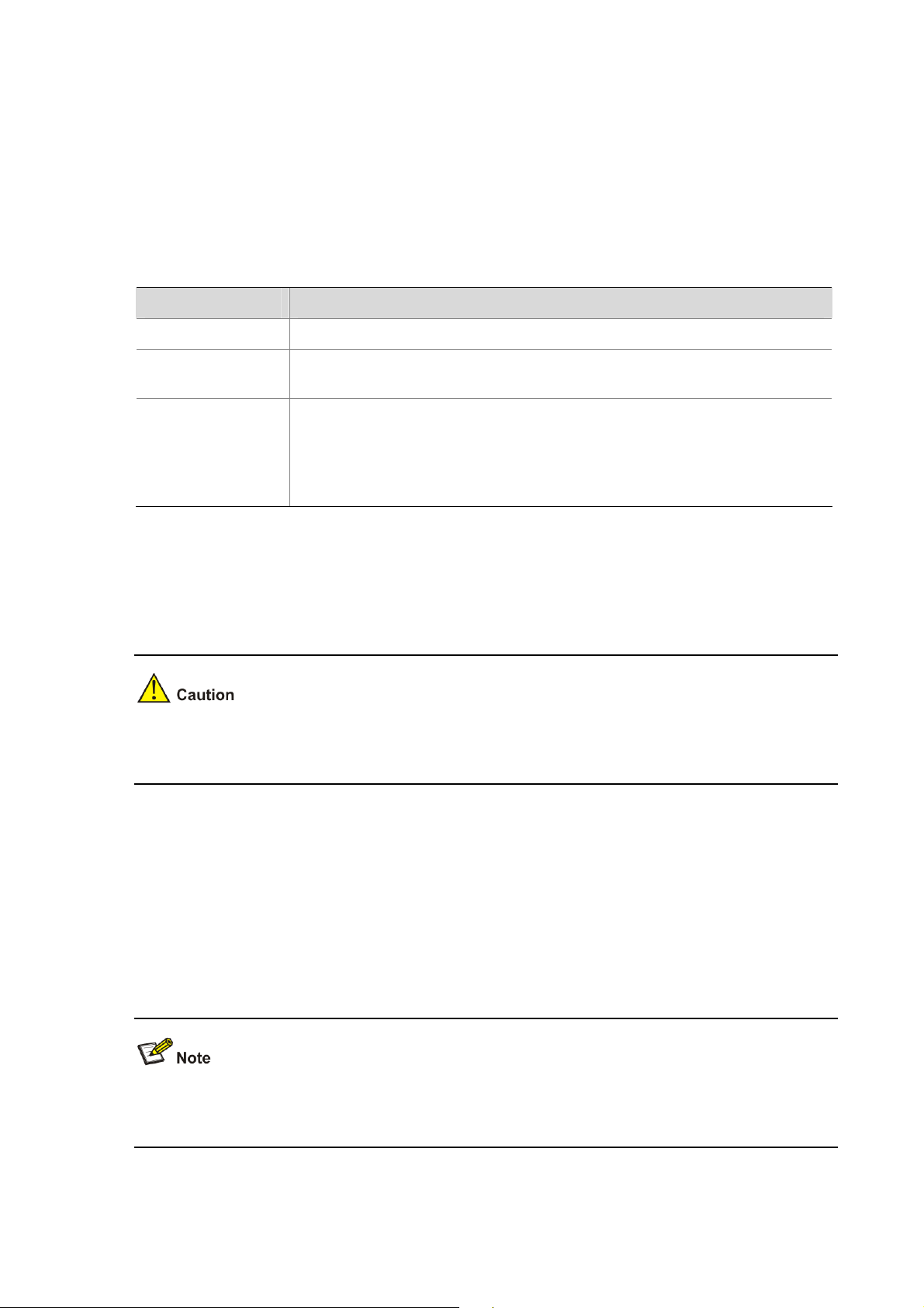
Table 1-1 Hardware Features
Feature Description
Addresses Up to 8192 supported.
Auto-negotiation Supported on all ports.
1-1
Page 10
Feature Description
Forwarding Modes
Store and Forward.
Duplex Modes Half and full duplex on all front panel ports.
Auto MDI/MDIX
Supported on all ports. If fiber SFP transceivers are used,
Auto MDIX is not supported.
Flow Control In full duplex operation all ports are supported.
Traffic Prioritization Four traffic queues per port.
10/100 Mbps ports.
Each port automatically determines the speed and duplex
Ethernet Ports
mode of the connected equipment and provides a suitable
switched connection. The 10/100 Mbps ports can operate in
either half-duplex or full-duplex mode.
The 2 Gigabit combo ports support fiber Gigabit Ethernet
short-wave (SX) and long-wave (LX) SFP transceivers in
any combination. This offers you the flexibility of using SFP
Gigabit Combo Ports
transceivers to provide connectivity between the Switch and
a 1000 Mbps core network.
When an SFP port is in operation, the corresponding
1000BASE-T port is disabled. The 1000 Mbps connections
can only operate in full duplex mode.
Mounting 19-inch rack or standalone mounting.
Fanless design (supported by
Baseline Switch 2226-SFP Plus and
Baseline Switch 2250-SFP Plus)
PoE (Only supported by Baseline
Switch 2426-PWR Plus)
Front View Detail
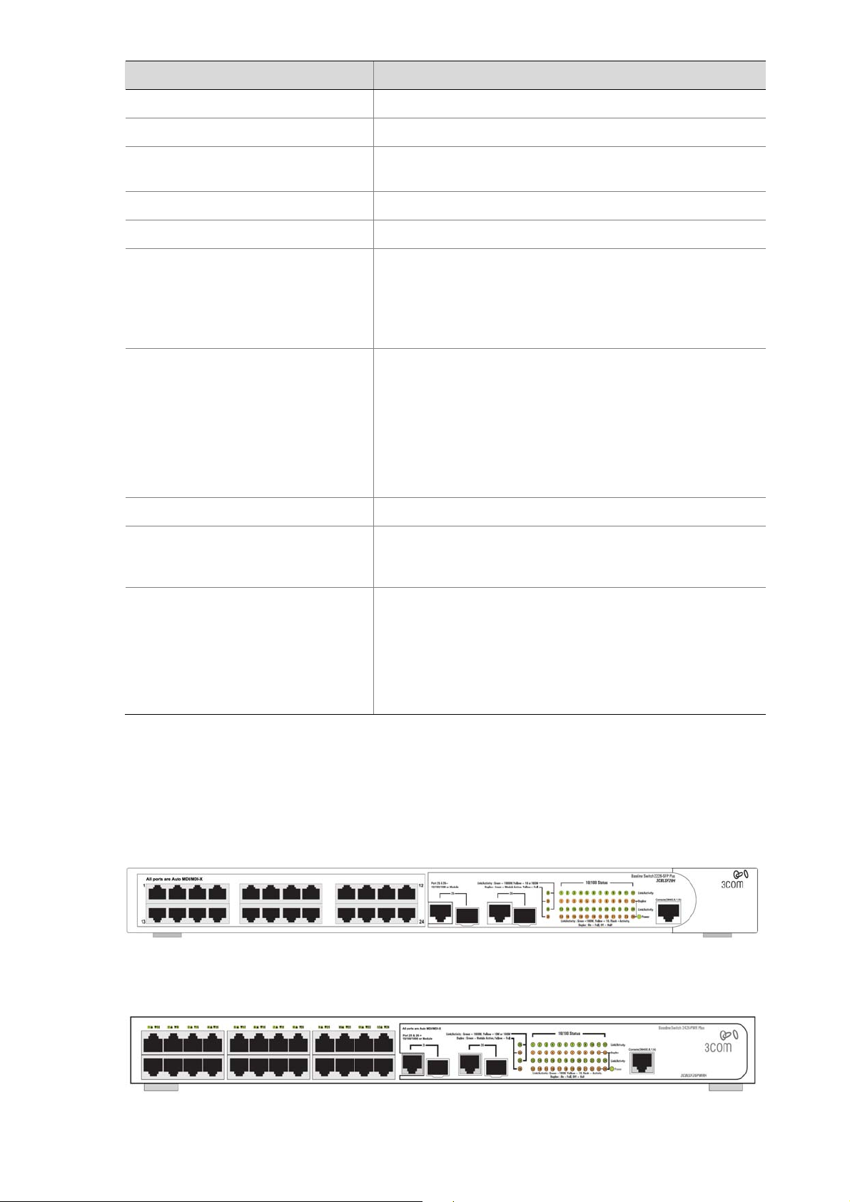
Figure 1-1 shows the front panel of the Baseline Switch 2226-SFP Plus 26-Port unit.
Figure 1-1 Baseline Switch 2226-SFP Plus 26-Port—front panel.
Silent operation whether used in a rack or desktop situation.
Each RJ-45 port supports the IEEE 802.3af PoE standard.
Any 802.3af compliant device attached to a port can directly
draw power from the switch over the Ethernet cable without
requiring its own separate power source. This capability
gives network administrators centralized power control for
devices such as IP phones and wireless access points,
which translates into greater network availability.
Figure 1-2 Shows the front panel of the Baseline Switch 2426-PWR Plus 26-Port unit.
Figure 1-2 Baseline Switch 2426-PWR Plus 26-Port—front panel.
Figure 1-3 shows the front panel of the Baseline Switch 2250-SFP Plus 50-Port unit.
1-2
Page 11
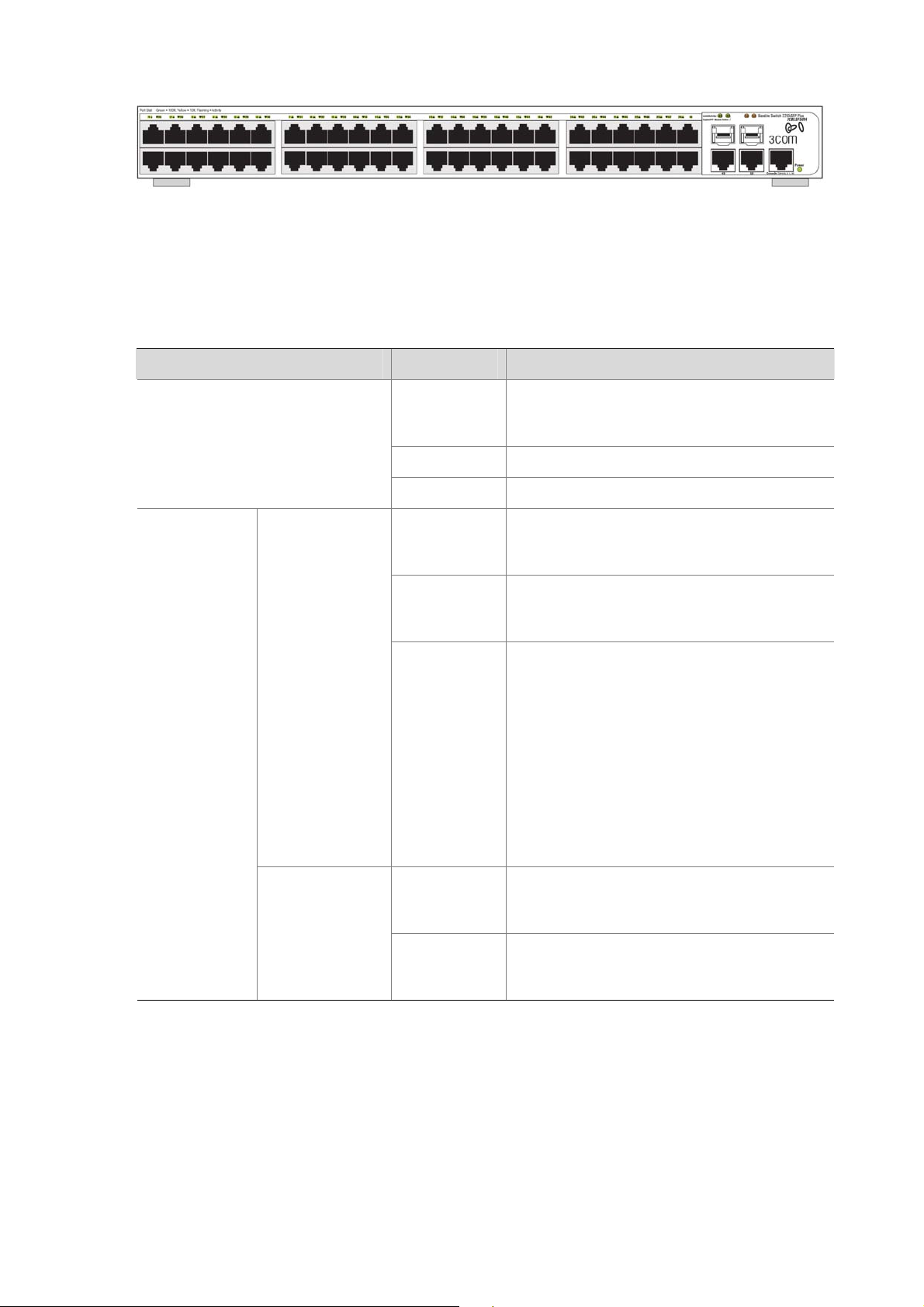
Figure 1-3 Baseline Switch 2250-SFP Plus 50-Port—front panel.
LED Status Indicators
The Switch provides LED indicators on the front panel f or your convenience to monitor the switch. Table
1-2 describes the meanings of the LEDs.
Table 1-2 Description on the LEDs of the Switch
LED Status Description
Power
The switch starts normally. The LED flashes
Green
when the system is performing Power-On
Self-Test (POST).
Yellow The system has failed the POST.
OFF The switch is powered off.
Link/Activity
10/100BASE-T
port
10/100/1000BAS
E-T port
Green
Yellow
OFF
Green
Yellow
The port works at the rate of 100 Mbps; the
LED flashes quickly when the port is sending
or receiving data.
The port works at the rate of 10 Mbps; the
LED flashes quickly when the port is sending
or receiving data.
The link has not been established, either
nothing is connected to the port, or there is a
problem:
z Check that the attached device is powered
on.
z Check that the cable is the correct type
and is not faulty.
If these checks do not identify the cause of the
problem, it may be that the unit or the device
connected to the port is faulty. Contact your
supplier for further advice.
The port works at the rate of 1000 Mbps; the
LED flashes quickly when the port is sending
or receiving data.
The port works at the rate of 10/100 Mbps; the
LED flashes quickly when the port is sending
or receiving data.
1-3
Page 12

LED Status Description
The link has not been established, either
nothing is connected to the port, or there is a
problem:
z Check that the attached device is powered
on.
z Check that the cable or fiber is the correct
OFF
type and is not faulty.
z For fiber connections, ensure that the
receive (RX) and transmit (TX) cable
connectors are not swapped.
If these checks do not identify the cause of the
problem, it may be that the unit or the device
connected to the port is faulty. Contact your
supplier for further advice.
Duplex
10/100/1000BAS
E-T port
Module Active SFP port
PoE Power (Only supported by
Baseline Switch 2426-PWR Plus)
System Specifications
Table 1-3 contains the system specifications of the Switch.
Table 1-3 System specifications of the Switch.
Specification 2226-SFP 2426-PWR 2250-SFP
Physical dimensions
(H×W×D)
Yellow The port is in full duplex mode.
OFF
Green The SFP module is inserted.
OFF
Green
OFF
44 mm×440 mm×170
mm
The port is not connected, or is in half duplex
mode.
The SFP module is not inserted or is not
recognized.
The port is supplying power to the device
connected to it.
The port is not supply power to the device
connected to it or not connected.
44 mm×440 mm×238
mm
44 mm×440 mm×238
mm
Weight 1.6 kg 3.2 kg 2.9 kg
Console port 1 1 1
24 (Each port can
Ethernet port 24
provide a power
48
supply of 25 W)
Gigabit Combo port 2 2 2
AC Input voltage
Power consumption (full
load)
Rated voltage range:
100–240V AC, 50/60
Hz
17 W 205 W 26 W
Rated voltage range:
100–240V AC, 50/60
Hz
Rated voltage range:
100–240V AC, 50/60
Hz
Operating temperature 0°C to 40°C (32°F to 113°F)
Storage temperature –10°C to +70°C (14°F to 158°F)
1-4
Page 13

Specification 2226-SFP 2426-PWR 2250-SFP
Operating humidity
(noncondensing)
Storage humidity
(noncondensing)
Installing the Switch
This section contains information that you need to install and set up the switch. It covers the following
topics:
z Before You Begin
z Package Contents
z Positioning the Switch
z Rack-Mounting or Free-Standing
z Supplying Power to the Switch
z Checking for Correct Operation
z Using SFP Transceivers
z Performing Spot Checks
20% to 85%
10% to 90%
Before You Begin
Before installing or removing any components from the switch or carrying out any maintenance
procedures, read the safety information provided in
Package Contents
The Baseline Switch packaging contains the following for all units:
z One product sealed in a plastic bag
z One CD
z One Safety and Regulatory Information manual
z One warranty card
z One Mounting Kit
z One DB-9 to RJ-45 cable
Positioning the Switch
The switch is suitable for use in an office environment where it can be free-standing or mounted in a
standard 19-inch equipment rack.
Alternatively, the switch can be rack-mounted in a wiring closet or equipment room. A mounting kit,
containing two mounting brackets and four screws, is supplied with the swit ch.
Safety Information of this guide.
When deciding where to position the switch, ensure that:
z It is accessible and cables can be connected easily.
z Cabling is away from sources of electrical noise. These include lift shafts, microwave ovens, and
air conditioning units. Electromagnetic fields can interfere with the signals on copper cabling and
introduce errors, therefore slowing down your network.
z Water or moisture cannot enter the case of the unit.
1-5
Page 14
z Air flow around the unit and through the vents on the side of the case is not restricted (3Com
recommends that you provide a minimum of 25 mm (1 in.) clearance).
z The air is as free from dust as possible.
z Temperature operating limits are not likely to be exceeded. It is recommended that the unit is
installed in a clean, air conditioned environment.
It is always good practice to wear an anti-static wrist strap when installing network equipment,
connected to a ground point. If one is not available, try to keep in contact with a grounded rack and
avoid touching the unit's ports and connectors, if possible. Static discharge can cause reliability
problems in your equipment.
Rack-Mounting or Free-Standing
The unit can be mounted in a 19-inch equipment rack using the mounting kit or it can be free standing.
Do not place objects on top of the unit or stack.
If installing the switch in a free-standing stack of different size Baseline or Super stack 3 units, the
smaller units must be installed above the larger ones. Do not have a free-standing stack of more than
six units.
Using the Mounting Kit
The switch is supplied with two mounting brackets and four screws. These are used for rack mounting
the unit. When mounting the unit, you should take note of the guidelines given in
Positioning the Switch.
The switch is 1U (1.7 inches) high and will fit in a standard 19-inch rack.
Disconnect all cables from the unit before continuing. Remove the self-adhesive pads from the
underside of unit, if already fitted.
To rack-mount the switch:
1) Place the unit the right way up on a hard, flat surface with the front facing towards you.
2) Locate a mounting bracket over the mounting holes on one side of the unit.
3) Insert the two screws supplied in the mounting kit and fully tighten with a suitable screwdriver.
1-6
Page 15
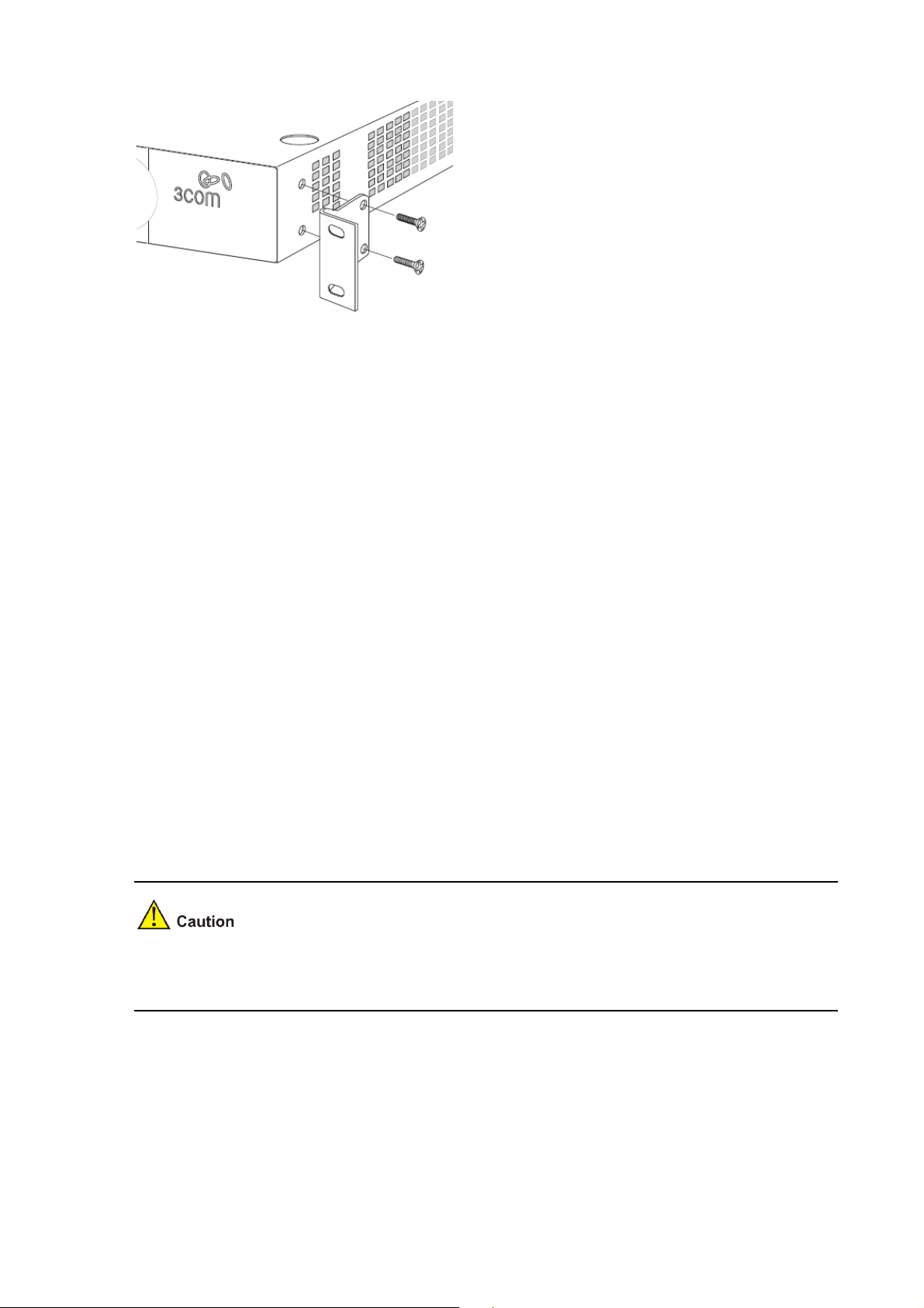
Figure 1-4 Rack Mounting the Unit
4) Repeat steps 2 and 3 for the other side of the unit.
5) Insert the unit into the 19-inch rack and secure with suitable screws (not provided).
6) Reconnect the cables.
Placing Units On Top of Each Other
If the switch units are free-standing, up to six units can be placed one on top of the other. If you are
mixing a variety of Baseline and Super Stack units, the smaller units must be positioned at the top.
If you are placing switch units one on top of the other, you must use the self-adhesive rubber pads
supplied. Apply the pads to the underside of each switch, sticking one in the marked area at each
corner.
Place the switch units on top of each other, ensuring that the pads of the upper unit line up with the
recesses of the lower unit.
Supplying Power to the Switch
Power problems can be the cause of serious failures and downtime in your network. Ensure that the
power input to your system is clean and free from sags and surges to avoid unforeseen network
outages. 3Com recommends that you install power conditioning, especially in areas prone to blackout,
power dips and electrical storms.
The unit is intended to be grounded. Ensure it is connected to earth ground during normal use. Installi ng
proper grounding helps to avoid damage from lightning and power surges.
Before powering on the switch, verify that the network cables and the power cable are securely
connected.
To power on the switch:
1) Plug the power cord into the power socket on the rear panel of the switch.
2) Plug the other end of the power cord into a power outlet.
1-7
Page 16
Checking for Correct Operation
After you power on the switch, it automatically performs a power-on self-test (POST). During POST, the
Power LED on the front panel of the switch flashes green.
When POST is complete, the Power LED turns green. If the Power LED turns yellow after POST, it
means that POST failed and the switch has entered fail-safe mode.
The following summarizes the possible colors for the Power LED after POST.
Table 1-4 Summarizes the possible colors for the Power LED after POST
Status Meaning
Green The unit is powered on and ready for use.
Yellow
Power-on self-test or loop back test failed. The switch is in fail-safe mode.
This can happen if a port or ports fail when the switch was powered on.
The unit is not receiving power.
Off
z Verify that the power cord is connected correctly, and then try powering on
the switch again
z If the switch still does not operate, contact your 3Com network supplier
If POST fails, try the following:
z Power off the switch, and then power it on again. Check the Power LED and see if POST was
successfully completed.
z Reset the switch. See Resetting to Factory Defaults.
Resetting the switch to its factory default erases all your settings. You will need to reconfig ure the switch
after you reset it.
If these do not resolve the issue:
z Check the 3Com Knowledgebase for a solution. To visit the 3Com Knowledgebase Web site, start
your Web browser, and then enter http://knowledgebase.3com.com.
z Contact your 3Com network supplier for assistance.
Using SFP Transceivers
The following sections describe how to insert an SFP transceiver into an SFP slot.
SFP transceivers are hot-insertable and hot-swappable. You can remove them from and insert them
into any SFP port without having to power down the switch.
1-8
Page 17
Approved SFP Transceivers
The following list of approved SFP transceivers is correct at the time of publication:
z 3CSFP91 SFP (SX)
z 3CSFP92 SFP (LX)
To access the latest list of approved SFP transceivers for the switch on the 3Com Web site, enter this
URL into your Internet browser: http://www.3com.com
3Com recommends using 3Com SFPs on the switch. If you insert an SFP transceiver that is not
supported, the switch will not recognize it.
Inserting an SFP Transceiver
To be recognized as valid, the SFP transceiver must have the following characteristics:
1000BASE-SX or 1000BASE-LX media type:
z 1000BASE-SX SFP transceiver
Use this transceiver to connect the switch directly to a multimode fiber-optic cable.
z 1000BASE-LX SFP transceiver
Use this transceiver to connect the switch directly to a single mode fiber-optic cable or to multi-mode
fiber using a conditioned launch cable.
To activate the SFP port:
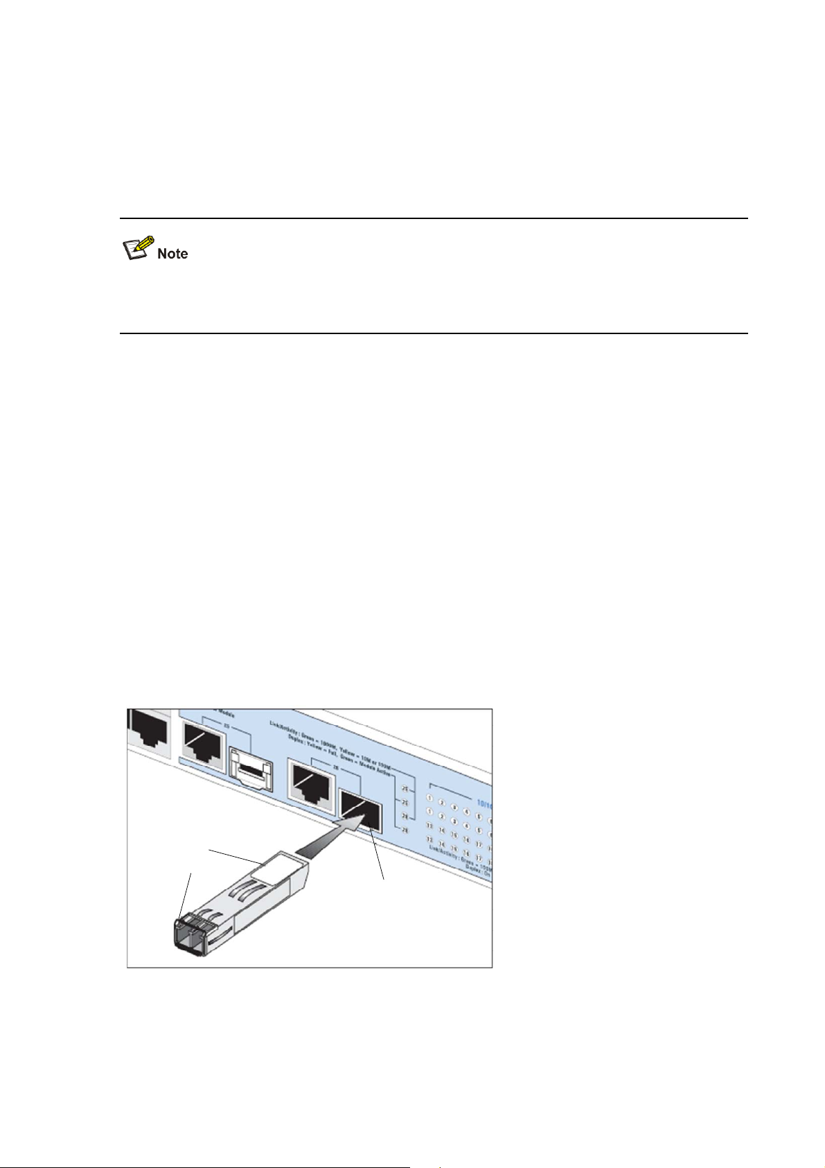
1) Hold the transceiver so that the fiber connector is toward you and the product label is visible, as
shown in
Figure 1-5.Ensure the wire release lever is closed (in the upright position).
Figure 1-5 Inserting an SFP Transceiver
Product label
Product label
Wire release lever
Wire release lever
Suitable slot on
Suitable slot on
host Switch
host Switch
2) Gently slide the transceiver into the SFP slot until it clicks into place.
1-9
Page 18

SFP transceivers are keyed and can be properly inserted only one way. If the transceiver do es not click
when you insert it, remove it, turn it over, and reinsert it.
3) Remove the plastic protective cover, if fitted.
4) Connect the fiber cable.
5) Attach a male duplex LC connector on the network cable into the duplex LC connector on the
transceiver.
6) Connect the other end of the cable to a device fitted with an appropriate Gigabit Ethernet
connection.
7) Check the Module Active LEDs on the front of the switch to ensure that the SFP transceiver is
operating correctly.
Removing an SFP Transceiver
To remove an SFP transceiver:
1) Disconnect the cable from the transceiver.
2) Move the wire release lever downwards until it is pointing toward you.
3) Pull the wire release lever toward you to release the catch mechanism.
The SFP transceiver should slide out easily.
Performing Spot Checks
At frequent intervals, you should visually check the switch. Regular checks can give you an early
warning of a possible failure; any problems can then be attended to when there will be least effect on
users.
3Com recommends periodically checking the items listed in
Table 1-5 Items to Check
Item Operation
Where possible, check that the cooling fan is operating by listening to the unit.
Cooling fan
Cabling
The fan is fitted near to the front right hand side of the unit (when viewed from
the front).
Check that all external cabling connections are secure and that no cables are
pulled taut.
Table 1-5.
Configuring IP Address
The switch’s IP configuration is determined automatically using DHCP, or manually using values you
assign.
By default, the switch will use its default IP information. The default IP address is 169.254.xxx.xxx. If the
MAC address is 08004E000102, the IP address would be 169.254.1.2.
1-10
Page 19

Automatic IP Configuration using DHCP
When you use the automatic IP configuration method, the switch tries to obtain it s IP information without
requesting user intervention from a DHCP server on the network.
You should use the automatic IP configuration method if:
z Your network uses DHCP to allocate IP information, or
z Flexibility is needed. If the switch is deployed onto a different subnet, it will automatically
reconfigure itself with an appropriate IP address, instead of you ha ving to manually reconfigure the
switch.
You can use ip address dhcp-alloc command to define automatic IP configuration method and use
display ip command to view the automatically allocated IP Information through the Console Port (see
CLI Reference Guide).
Manual IP Configuration
When you configure the IP information manually, the switch remembers the information that you enter
until you change it again.
You should use the manual IP configuration method if:
z You do not have a DHCP server on your network, or
z You want to remove the risk of the IP address ever changing, or
z Your DHCP server does not allow you to allocate static IP addresses.
For most installations, 3Com recommends that you configure the switch IP information manually. This
makes management simpler and more reliable as it is not dependent on a DHCP server, and eliminate s
the risk of the IP address changing.
You can use ip address command to configure the static IP for your switch through the Console Port
CLI Reference Guide).
(see
1-11
Page 20

2 Connecting To the Web Interface
The switch has a built-in Web interface that you can use to set the user password, change the IP
address that is assigned to the switch, and configure its advanced setting s.
This chapter introduces the setting the menu items and buttons that are available on the Web interface.
The following topics are covered:
z Requirements for Accessing the Web Interface
z Choosing a Web Browser
z Default User and Password
z Logging On to the Web Interface
z Navigating the Web Interface
Requirements for Accessing the Web Interface
To connect to the Web interface, you need the following:
z Ensure that the switch is connected to the network using a Category 5 twisted pair Ethernet cable
with RJ-45 connectors.
z Ensure that you know your switch’s IP address. See Configuring IP Address.
z Check that your management workstation is on the same subnet as your switch.
z Choose a suitable Web browser.
Choosing a Web Browser
To display the Web interface correctly, use one of the following Web browsers and platform
combinations:
Table 2-1 Supported Web Browsers and Platforms
Platform
Browser
Internet Explorer 6 Yes Yes Yes
Internet Explorer 7 Yes Yes Yes
Firefox 1.5 Yes Yes Yes
Windows 2000 Windows XP Windows Vista
Firefox 2 Yes Yes Yes
Netscape 8 Yes Yes Yes
For the browser to operate the Web interface correct ly , JavaS cript and Cascading S tyle Sheets must b e
enabled on your browser. These features are enabled on a browser by default. You will only need to
enable them if you have changed your browser settings.
2-1
Page 21
Default User and Password
If you intend to manage the switch or to change the default password, you must log in with a v alid u ser
name and password. The switch has one default user name. The default user is listed in
Table 2-2 Default User and Password
User Name Default Password Access Level
Table 2-2.
admin -
Logging On to the Web Interface
To log on to the Web interface, do the following:
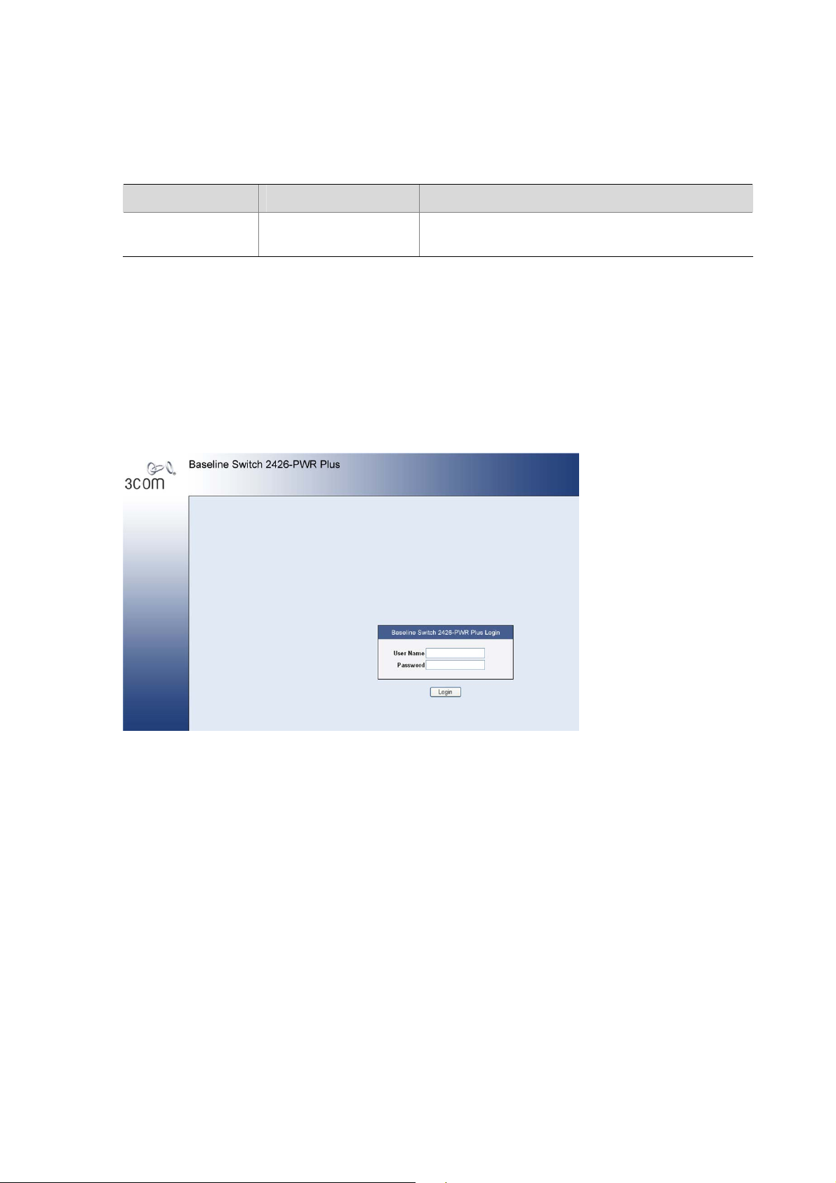
1) Open your Web browser and enter the IP address of the switch that you wish to manage in the URL
locator (For example, in the following format: http://xxx.xxx.xxx.xxx). The Login Page appears:
Figure 2-1 Login Page
Management: The user can access and change all
manageable parameters
2) Enter admin as your user name and leave the password field blank.
3) Click Login, The main Web interface page is displayed.
Navigating the Web Interface
The Web interface has been designed to enable you to easily perform advanced configuration tasks
and view information about the switch.
Menu
The menu is located on the left side of the Web interface. When you click an item on the menu, the
related screen appears in the main part of the interface. Some menu items will give you sub-menu tabs
to choose from.
2-2
Page 22
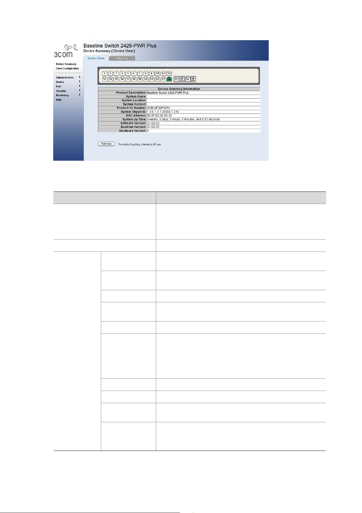
Figure 2-2 Switch Screen Layout
Table 2-3 Available Menu Items
Menu Item Description
Device Summary
Save Configuration
Administration
Contains tabs that allow you to:
z Provide a summary of the switch’s basic settings and
versions of current components.
z Display the description for each color coded port.
IP Setup
ARP Setting
Saves the switch’s configuration
Allows you to setup, modify, or view the IP configuration
parameters.
Allows a host to communicate with other hosts when only the
IP address of its neighbors is known.
Backup & Restore Allows you to backup and restore the switch’s configuration.
Firmware
Upgrade
Allows you to upgrade the current firmware via HTTP
Reset Allows you to reset the switch to factory default settings
Contains tabs that allow you to:
z Display user summary information.
System Access
z Create a new user.
z Modify existing users.
z Remove existing users.
System Name Allows you to set the system name.
System Time Allows you to set the system time.
Logging
System Logs record and manage events and report errors
and informational messages
Contains tabs that allow you to:
SNMP
z Add community strings.
z Remove community strings.
2-3
Page 23

Menu Item Description
Contains tabs that allow you to:
z Create a VLAN.
z Modify a VLAN.
VLAN
z Modify VLAN membership for a port.
z Rename a VLAN.
z Remove a VLAN.
z Display VLAN membership for a port.
z Display VLAN information.
Allows you to configure a Spanning Tree Protocol.
Contains tabs that allow you to:
Spanning Tree
z Display selected spanning tree information for every port.
z Display individual port spanning tree information.
z Modify the spanning tree settings for a port.
Device
IGMP Snooping
Allows you to enable or disable IGMP snooping and IGMP
query modes.
Broadcast Storm Allows you to enable or disable broadcast control.
ACL Configures the ACL.
MAC Based ACL Configures MAC Based ACL on the switch.
IP Based ACL Configures IP Based ACL on the switch.
ACL Binding Configures ACL Binding on the switch.
QoS Configures QoS settings.
Contains tabs that allow you to:
CoS
z Displays CoS default settings assigned to ports.
z Defines CoS
Queue Configures Queue Setting.
CoS to Queue Displays and defines CoS to Queue.
DSCP to Queue Contains fields for mapping DSCP settings to traffic queues.
Trust Configures Trust Settings.
Bandwidth Displays and defines Bandwidth Settings.
Contains tabs that allow you to:
z Display Voice VLAN summary.
VoIP Traffic
Setting
z Configure Voice VLAN global settings.
z Configure Voice VLAN port settings.
z Display port information for Voice VLAN.
z Display OUI summary.
z Add or remove OUI.
LLDP Allows you to configure LLDP global and port settings.
2-4
Page 24

Menu Item Description
Contains tabs that allow you to:
Administration
z Display selected port information for the entire switch.
z Display individual port information.
z Modify the port settings.
Contains tabs that allow you to:
z Display link aggregation summary.
Link Aggregation
Port
z Create an aggregation group.
z Modify the port memberships.
z Remove an aggregation group.
LACP Configures the LACP.
Statistics Display statistics for a selected port.
Security
Monitoring
Help
PoE(Only
supported by
2426-PWR Plus)
Contains tabs that allow you to:
z Display PoE summary.
z Configure PoE settings.
Contains tabs that allow you to:
Radius Client
z Display Radius Client information.
z Configure Radius Client settings and set authentication
parameters.
Contains tabs that allow you to:
802.1X
z Display system authentication summary.
z Display detailed information per port.
z Configure system authentication settings.
Address Table Displays MAC address table information for ports and VLANs.
Port Mirroring Monitor traffic going in or out of ports.
Contains tabs that allow you to:
Cable
Diagnostics
z Display selected cable diagnostics information for all
ports.
z Display all cable diagnostics information for a single port.
Displays 3Com contact information and describes how to use
the online help system.
Logout
Buttons
Depending on the screen that is currently displayed, the following buttons may appear:
z Apply: Click to apply any changes that you have made.
z Cancel: Click to discard any unsaved changes.
z Select All: Allows the user to select all ports.
z Select None: Removes the ports selected.
z Help: Click to display the context-sensitive help information for the screen that is currently
Allows you to securely log off the Web interface.
displayed. The help pages provide information on the tasks that you can perform on each screen.
2-5
Page 25
3 Configuring the Switch
Configuring System Access
Network administrators can define user name, password, and access level for users using the System
Access Interface. The Multi-Session Web feature is enabled on switch and allows 10 users to be
created and access the switch concurrently. Access levels provide read or read/write permissions to
users for configuring the switch. Login information is managed in the local dat abase. A unique password
is required of each user. Two access le vels exist on the Web Interface:
z Management access level: Provides the user with read/write access rights. There is always one
management level user configured for the switch.
z Monitor access level: Provides the user with read-only system access rights.
This section contains the following topics:
z Defining System Access
z Modifying System Access
z Removing System Access
z Viewing System Access Settings
To ensure that unauthorized users do not access the Web interface, 3Com reco mmends that you set an
admin password when you first configure the switch.
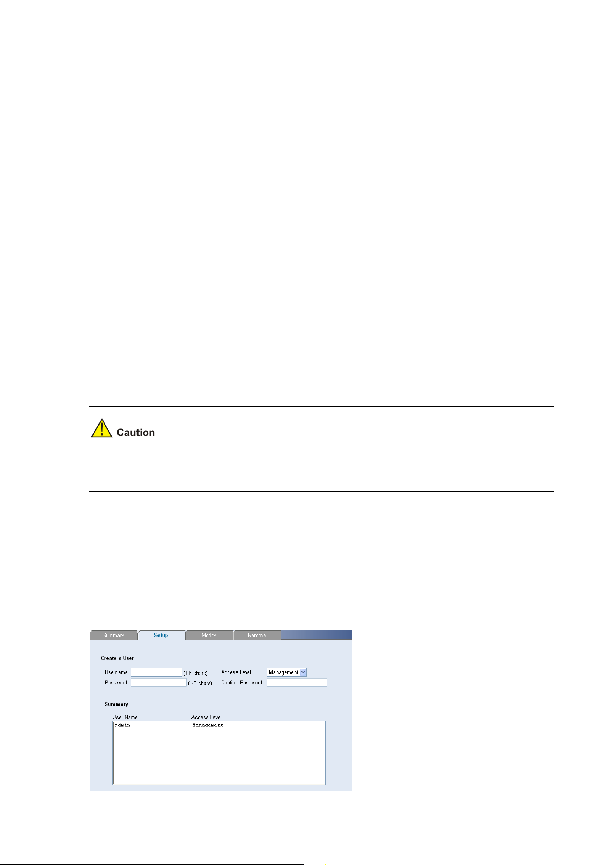
Defining System Access
The System Access Setup Page allows network administrators to define users, passwords, and access
levels for users using the System Access Interface.
Click Administration > System Access > Setup. The System Access Setup Page opens.
Figure 3-1 System Access Setup Page
3-1
Page 26
The System Access Setup Page contains the following fields:
Table 3-1 System Access Setup Page item description
Item Description
User Name Defines the user name. The default value is admin.
Access Level
Password Defines the local user password. The default is blank.
Confirm Password Verifies the password.
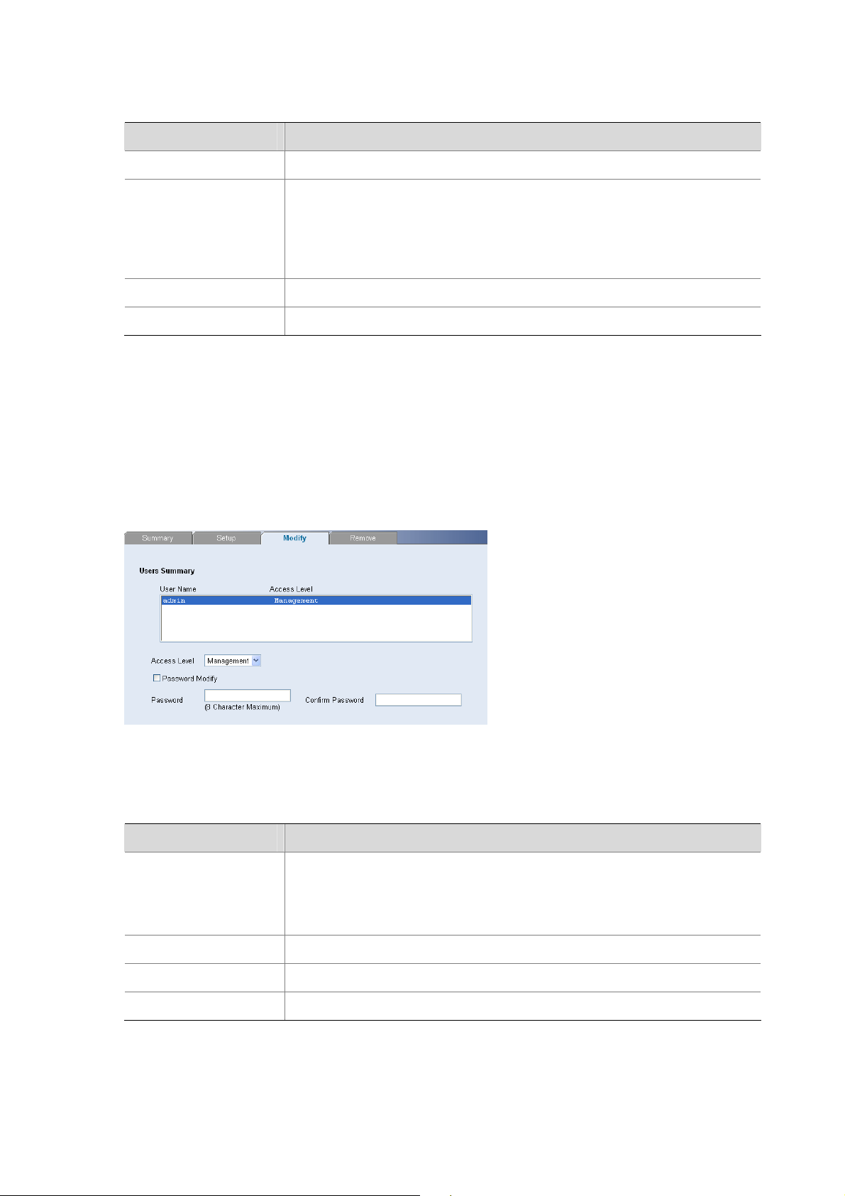
Modifying System Access
The System Access Modify Page allows network administrators to modify users, passwords, and
access levels for users using the System Access Interface.
Defines the user access level. The lowest user access level is Moni tor and
the highest is Management.
z Management: Provides the user with read and write access right s. This
is the default.
z Monitor: Provides the user with read access rights.
Click Administration > System Access > Modify. The System Access Modify Page opens.
Figure 3-2 System Access Modify Page
The System Access Modif y Page contains the following fields:
Table 3-2 System Access Modify Page item description
Item Description
Defines the user access level. The lowest user access level is Moni tor and
Access Level
the highest is Management.
z Management: Provides the user with read and write access rights.
z Monitor: Provides the user with read access rights.
Password Modify Enables modifying a password for an existing user.
Password Modifies the local user password.
Confirm Password Verifies the password.
3-2
Page 27
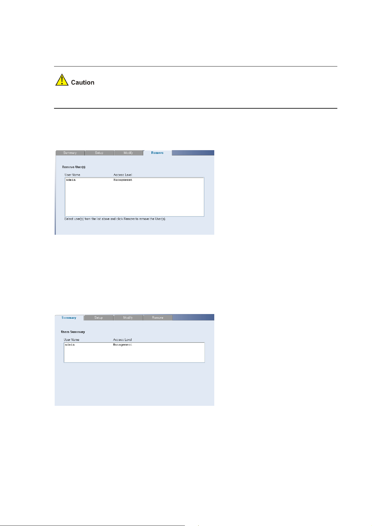
Removing System Access
The System Access Remove Page allows network administrators to remove users from the System
Access Interface.
The last user with management access may not be deleted.
Click Administration > System Access > Remove. The System Access Remove Page opens.
Figure 3-3 System Access Remove Page
Viewing System Access Settings
The System Access Summary Page displays the current users and access levels define d on the switch.
Click Administration > System Access > Summary. The System Access Summary Page opens.
Figure 3-4 System Access Summary Page
The System Access Summary Page contains the following fields:
3-3
Page 28
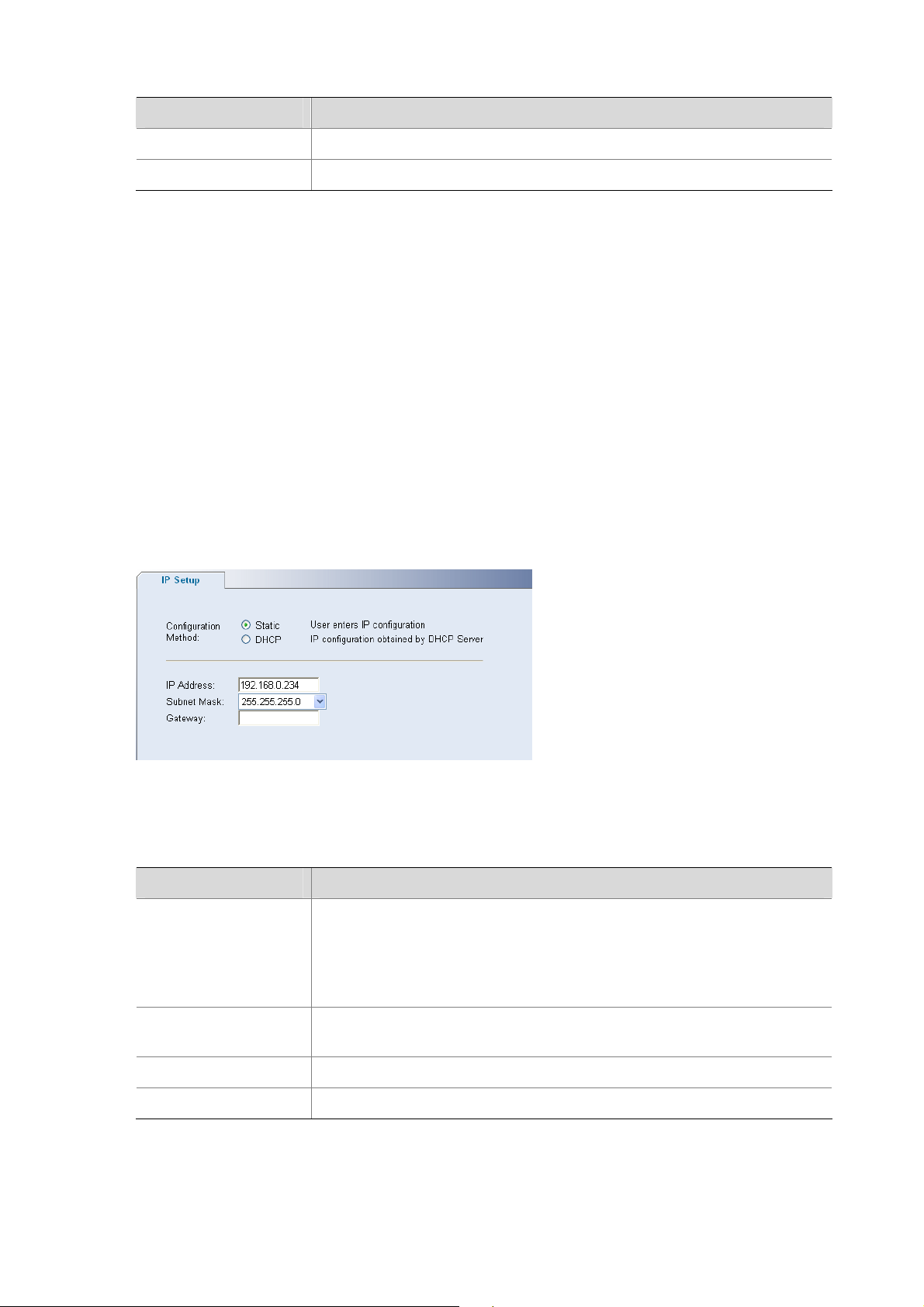
Table 3-3 System Access Summary Page item description
Item Description
User Name Displays the user name.
Access Level Displays the user access level.
Configuring IP and MAC Address Information
This section contains information for defining IP interface s, and in cludes the following sections:
z Defining IP Address
z Configuring ARP Settings
z Configuring MAC Address Table
Defining IP Address
To enable the other devices on the network to communicate with the switch, you need to assign an IP
address to it: either by DHCP or by assigning a static IP address.
Click Administration > IP Setup. The IP Setup Page open s.
Figure 3-5 IP Setup Page
The IP Setup Page contains the following fields:
Table 3-4 IP Setup Page item description
Item Description
Defines whether the IP address is configured staticall y or dynamically. The
possible field values are:
Configuration Method
z Static: Specifies that the IP address is configured by the user.
z DHCP: Specifies that the IP address is dynamically obtained by DHCP
Server.
IP Address
Defines the IP address. The default value is 169.254.xxx.xxx. If the MAC
address is 08004E000102, the IP address would be 169.254.1.2.
Subnet Mask Defines the subnet mask. The default value is 255.255.0.0.
Gateway Defines the gateway address. The default value is blank.
3-4
Page 29
Configuring ARP Settings
The Address Resolution Protocol (ARP) converts IP addresses into physical addresses, and maps the
IP address to a MAC address. ARP allows a host to communicate with other hosts when only the IP
addresses of its neighbors are known.
This section includes the following topics:
z Defining ARP Settings
z Removing ARP Entries
z Viewing ARP Settings
Defining ARP Settings
The ARP Settings Setup Page allows network managers to define ARP parameters for specific
interfaces.
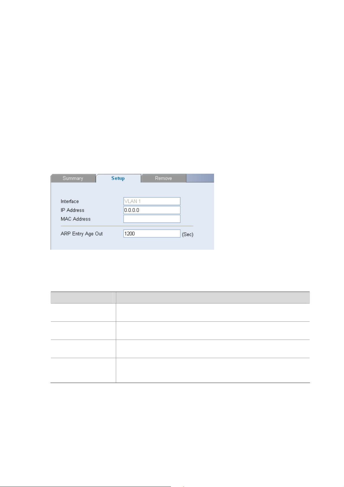
Click Administration > ARP Settings > Setup. Th e ARP Settings Setup Page opens.
Figure 3-6 ARP Settings Setup Page
The ARP Settings Setup Page contains the following fields:
Table 3-5 ARP Settings Setup Page item description
Item Description
Interface
IP Address
MAC Address
Indicates the management VLAN (VLAN 1) for which ARP parameters are
defined.
Defines the static IP address, which is associated with the static MAC
address.
Defines the static MAC address, which is associated with the static IP
address.
Specifies the aging time for dynamic ARP entries. After the ARP Entry
ARP Entry Age Out
Age, dynamic ARP entries are deleted from the table. The range is
1-40000000. The default value is 1200 seconds.
Removing ARP Entries
The ARP Entries Remove Page provides parameters for removing ARP entries from the ARP Table.
Click Administration > ARP Settings > Remove. The ARP Entries Remove Page opens.
3-5
Page 30

Figure 3-7 ARP Entries Remove Page
The ARP Entries Remove Page contains the following fields:
Table 3-6 ARP Entries Remove Page item description
Item Description
Specifies the types of ARP entries that are cleared. The possible values
are:
Clear ARP Table
Entries
z None: Maintains the ARP entries.
z All: Clears all ARP entries.
z Dynamic: Clears only dynamic ARP entries.
z Static: Clears only static ARP entries.
Interface Indicates the VLAN for which ARP parameters are defined.
IP Address Indicates the IP address which is associated with the MAC address.
MAC Address
Displays the MAC address, which is associated in the ARP table with the
IP address.
Displays the ARP table entry type. Possible field values are:
Status
z Dynamic: Indicates the ARP entry is learned dynamically.
z Static: Indicates the ARP entry is a static entry.
Viewing ARP Settings
The ARP Settings Summary Page displays the current ARP settings.
Click Administration > ARP Settings > Summary. The ARP Settings Summary Page opens.
3-6
Page 31

Figure 3-8 ARP Settings Summary Page
The ARP Settings Summary Page contains the following fields:
Table 3-7 ARP Settings Summary Page item description
Item Description
Interface Indicates the VLAN for which ARP parameters are defined.
IP Address Indicates the IP address, which is associated with the MAC Address.
MAC Address
Displays the station MAC address, which is associated in the ARP table
with the IP address.
Displays the ARP table entry type. Possible field values are:
Status
z Dynamic: Indicates the ARP entry is learned dynamically.
z Static: Indicates the ARP entry is a static entry.
Configuring MAC Address Table
MAC addresses are stored in either the static address or the dynamic address databases. A packet
addressed to a destination stored in one of the databases is forwarded immediately to the port.
The Dynamic Address Table can be sorted by interface, VLAN, and MAC address. MAC addresses are
dynamically learned as packets from sources arrive at the switch. MAC address es are associated with
ports by learning the ports from the frames source address. Frames addressed to a destination MAC
address that is not associated with any port are flooded to all ports of the relevant VLAN.
Static addresses are manually configured. In order to prevent the bridging table from overflowing,
dynamic MAC addresses, from which no traffic is seen for a certain period, are erased.
This section includes the following sections:
z Adding MAC Addresses to the Address Table
z Defining Aging Time
z Removing MAC Addresses for the specific port
z Removing MAC Addresses from the Address Table
z Viewing Address Table Settings
z Viewing Port Summary Settings
3-7
Page 32

Adding MAC Addresses to the Address Table
The Address Table Add Page allows the network manager to assign MAC addresses to ports with
VLANs.
Click Monitoring > Address Table > Add. The Address Table Add Page opens.
Figure 3-9 Address Table Add Page
The Address Table Add Page contains the following fields:
Table 3-8 Address Table Add Page item description
Item Description
VLAN ID Selects a VLAN ID.
MAC Address Defines a MAC address to be assigned to the specific port and VLAN ID.
Marks the aging status of the MAC address assigned by the user. The
possible values are:
No Aging
z Checked: Indicates that the Address Table entry assigned by the user is
not aged out.
z Unchecked: Indicates that the Address Table entry assigned by the user
is aged out.
Defining Aging Time
The Address Table Aging Time Setup Page allows the network manager to define the Address Table
Aging Time. The Aging Time is the amount of time the MAC addresses remain in the Dynamic Address
table before they are timed out if no traffic from the source is detected. The default value is 300
seconds.
Click Monitoring > Address Table > Setup. The Address Table Aging Time Setup Page opens.
3-8
Page 33

Figure 3-10 Address Table Aging Time Setup Page
Removing MAC Addresses for the specific port
The Port Remove Page allows the network manager to remove MAC Addresses for the specific port
from the Address Table.
Click Monitoring > Address Table > Port Remove. The Port Remove Page opens.
Figure 3-11 Port Remove Page
1) Select a port to remove MAC Addresses.
2) Select entries from the address table to be removed.
3) Click Remove.
Removing MAC Addresses from the Address Table
The Address Table Remove Page allows the network manager to remove current MAC addresses from
the Address T able.
Click Monitoring > Address Table > Remove. The Address Table Remove Page opens.
Figure 3-12 Address Table Remove Page
3-9
Page 34

1) Select entries from the address table to be removed.
2) Click Remove.
Viewing Address Table Settings
The Address Table Summary Page displays the current MAC address table configuration.
Click Monitoring > Address Table > Summary. The Address Table Summary Page opens.
Figure 3-13 Address Table Summary Page
The Address Table Summary Page contains the following fields:
Table 3-9 Address Table Summary Page item description
Item Description
Filters the list of MAC addresses displayed according to the type of MAC
address configuration. Possible values are:
State
MAC Address
z All: Displays all MAC addresses.
z Static: Displays the statically configured MAC addresses.
z Dynamic: Displays the dynamically learned MAC addresses.
Displays the current MAC addresses listed in the MAC address table,
filtered by the selected value of the State field.
VLAN ID Displays the VLAN ID associated with the port and MAC address.
Displays the MAC address configuration method. Possible values are:
State
z Config Static: Displays the statically configured MAC address.
z Config Dynamic: Displays the dynamically learned MAC address.
Port Index Displays the port through which the address was learned.
Displays that the MAC address is aged out or not.. Possible values are:
Aging Time
z NOAGED: Indicates that the MAC address is not aged out.
z AGING: Indicates that the MAC address is aged out.
Viewing Port Summary Settings
The Port Summary Page allows the network administrator to view the MAC addresses assigned to
specific ports.
Click Monitoring > Address Table > Port Summary. The Port Summary Page opens.
3-10
Page 35

Figure 3-14 Port Summary Page
The Port Summary Page contains the following fields:
Table 3-10 Port Summary Page item description
Item Description
Filters the list of MAC addresses displayed according to the type of MAC
address configuration. Possible values are:
State
z All: Displays all MAC addresses.
z Static: Displays the statically configured MAC addresses.
z Dynamic: Displays the dynamically learned MAC addresses.
MAC Address
VLAN ID Displays the VLAN ID associated with the port and MAC address.
State
Port Index Displays the port through which the address was learned.
Aging Time
Configuring Port
This section includes the following topics:
z Configuring Port Basic Settings
z Configuring PoE
z Viewing Port Statistics
Displays the current MAC addresses listed in the MAC address table,
filtered by the selected value of the State field.
Displays the MAC address configuration method. Possible values are:
z Config Static: Displays the statically configured MAC address.
z Config Dynamic: Displays the dynamically learned MAC address.
Displays that the MAC address is aged out or not.. Possible values are:
z NOAGED: Indicates that the MAC address is not aged out.
z AGING: Indicates that the MAC address is aged out.
Configuring Port Basic Settings
This section contains information for configuring Port Basic Settings, and includes the following topics:
z Defining Port Settings
z Viewing Port Settings
z Viewing Port Details
3-11
Page 36

Defining Port Settings
The Port Setup Page allows network managers to configure port parameters for specific ports.
Click Port > Administration > Setup. The Port Setup Page opens.
Figure 3-15 Port Setup Page
The Port Setup Page contains the following fields:
Table 3-11 Port Setup Page item description
Item Description
Port State
Flow Control
Speed
Enables and disables the port. The possible field values are:
z No Change: Retains the current port status.
z Enabled: Enables the port.
z Disabled: Disables the port.
Enables and disables flow control on the port. When flow control is enabled
for the port, the switch regulates the packet flow so that a sending device
does not transmit more packets than a receiving device can process. If flow
control is disabled, packets may be dropped under certain periods of high
traffic. The possible values are:
z No Change: Retains the current flow control status on the port.
z Enabled: Enables flow control on the port.
z Disabled: Disables flow control on the port.
Specifies the configured rate for the port. The port speed determines what
speed setting options are available. Port speeds can only be configured
when auto-negotiation is disabled. The possible field values are:
z No Change: Retains the current port speed.
z Auto: Use to automatically configure the port.
z 10: Indicates the port is currently operating at 10 Mbps.
z 100: Indicates the port is currently operating at 100 Mbps.
z 1000: Indicates the port is currently operating at 1000 Mbps.
Duplex
Specifies the port duplex mode. The possible field values are:
z No Change: Retains the current port duplex mode.
z Auto: Use to automatically configure the port.
z Full: The interface supports transmission between the switch and its link
partner in both directions simultaneously.
z Half: The interface supports transmission between the switch and its link
partner in only one direction at a time.
3-12
Page 37

z Before manually setting a port to full-duplex mode, verify that the device connected to the port is
also manually set to the same speed and duplex setting. If connecting link partners are left to autonegotiate for a link manually set on this switch to full-duplex, they will always negotiate to
half-duplex, resulting in a duplex mismatch. This can result in a significant reduction in network
performance. If you are unsure of how to configure the speed/duplex setting, simply enable autonegotiation for the port.
z 1000 Mbps connections are always full-duplex. Half-duplex connections are only available for 10
Mbps and 100 Mbps settings.
Viewing Port Settings
The Port Summary Page permits the network manager to view the current configura tion for all the ports.
Click Port > Administration > Summary. The Port Summary Page opens.
Figure 3-16 Port Summary Page
The Port Summary Page contains the following fields:
Table 3-12 Port Summary Page item description
Item Description
Indicates whether the port is currently operational or non-operational. The
State
possible field values are:
z Enabled: Indicates the port is currently operating.
z Disabled: Indicates the port is currently not operating.
Displays the flow control status on the port. The possible field values are:
Flow Control
z Enabled: Enables flow control on the port.
z Disabled: Disables flow control on the port.
3-13
Page 38

Speed
Duplex
PVID Indicates VLAN ID of this port for untagged packets.
Viewing Port Details
Item Description
Displays the configured rate for the port. The port type determines what
speed setting options are available. Port speeds can only be configured
when auto negotiation is disabled. The possible field values are:
z Auto: Use to automatically configure the port.
z 10M: Indicates the port is currently operating at 10 Mbps.
z 100M: Indicates the port is currently operating at 100 Mbps.
z 1000M: Indicates the port is currently operating at 1000 Mbps.
Displays the port duplex mode. The port speed is set to 10M or 100M or
1000M per second. The possible field values are:
z Auto: Use to automatically configure the port.
z Full: The interface supports transmission between the switch and its link
partner in both directions simultaneously.
z Half: The interface supports transmission between the switch and the
client in only one direction at a time.
The Port Detail Page displays the current port configuration for specific p orts.
Click Port > Administration > Detail. The Port Detail Page opens.
Figure 3-17 Port Detail Page
Configuring PoE
Power over Ethernet (PoE) provides power to devices over existing LAN cabling, without updating or
modifying the network infrastructure. Power over Ethernet removes the necessity of placing network
devices next to power sources.
PoE is only supported by 2426-PWR Plus.
This section contains the following topics:
z Defining Port PoE
z Viewing PoE
3-14
Page 39

Defining Port PoE
The Port PoE Setup Page allows the network manager to configure port PoE settings.
Click Port > PoE > Setup. The Port PoE Setup Page opens.
Figure 3-18 Port PoE Setup Page
The Port PoE Setup Page contains the following fields:
Table 3-13 Port PoE Setup Page item description
Item Description
Defines the port PoE state. The possible values are:
PoE State
PoE Mode for selected
& enabled ports
z Enable: Enables the port for PoE.
z Disable: Disables the port for PoE.
Defines the PoE mode for the selected port.
Displays guaranteed and total PoE power:
z Total PoE Available: The total amount of PoE power that can be
provided by the switch.
z Guarantee PoE: The maximum amount of PoE power that has been
Guarantee Power
Summary
guaranteed for selected ports. This value is defined by the number of
ports you have set to Guarantee.
z Remaining (Available - Guarantee): The minimum amount of
non-guaranteed PoE power left over after allocating the Guarantee
PoE power. This value is a guideline for assigning guarantee ports. The
actual amount of power used and available is displayed on the Port
PoE Summary page.
Selected Ports Displays the PoE configuration for the selected ports.
Viewing PoE
The Port PoE Summary Page displays the switch and port PoE settings.
Click Port > PoE. The PoE Summary Page opens.
3-15
Page 40

Figure 3-19 Port PoE Summary Page
The Port PoE Summary Page contains the following fields:
Table 3-14 Port PoE Summary Page item description
Item Description
Device
Power
Display
Ports
Power
Display
State
Power
Max(watts)
Power
Used(watts)
Power
Free(watts)
State
Mode
Indicates the power source status. The possible field values are:
z On: Indicates that the power supply unit is functioning.
z Off: Indicates that the power supply unit is not functioning.
z Faulty: Indicates that the power supply unit is functioning, but an error
has occurred. For example, a power overload or a short circuit.
Indicates the maximum amount of power the switch can supply. The field
value is displayed in Watts.
Indicates the actual amount of power currently used by the switch. The field
value is displayed in Watts.
Indicates the amount of additional power currently available to the switch.
The field value is displayed in Watts.
Indicates if the port is enabled to deliver power to powered devices. The
possible field values are:
z Enable: Indicates the switch is delivering power. This is the default.
z Disabled: Indicates the switch is not delivering power.
Indicates the port power mode. The possible field values are:
z Auto: Power is automatically allocated to the port, according to port
number. Lower numbered ports are assigned a higher priority for power
delivery. This is the default.
z Guarantee: Power is guaranteed to the selected port, provided that the
power is available. This setting overrides the priority assigned to lower
port numbers by the auto mode.
Power
Max(watts)
Power
Used(watts)
Viewing Port Statistics
The Port Statistics Summary Page contains fields for viewing information about switch utilization and
errors that occurred on the switch.
Indicates the maximum amount of power available to the interface. The field
value is displayed in Watts.
Indicates the actual amount of power currently used by the interface. The
field value is displayed in Watts.
3-16
Page 41

Click Port > Statistics > Summary. The Port Statistics Summary Page opens.
Figure 3-20 Port Statistics Summary Page
The Port Statistics Summary Page contains the following fields:
Table 3-15 Port Statistics Summary Page item description
Item Description
Defines the amount of time that passes before the interface statistics are
refreshed. The possible field values are:
Refresh Rate
z No Refresh: Indicates that the port statistics are not refreshed.
z 15 Sec: Indicates that the port statistics are refreshed every 15 seconds.
z 30 Sec: Indicates that the port statistics are refreshed every 30 seconds.
z 60 Sec: Indicates that the port statistics are refreshed every 60 seconds.
Clear All Counters Clears the port statistics counters and the new statistics are displayed.
Received Bytes
(Octets)
Displays the number of octets received on the interface since the switch wa s
last refreshed. This number includes bad packets and FCS octets, but
excludes framing bits.
Displays the number of packets received on the interface, including bad
Received Packets
packets, Multicast and broadcast packets, since the switch was last
refreshed.
Broadcast Packets
Received
Multicast Packets
Received
CRC & Align Errors
Displays the number of good broadcast packets received on the interface
since the switch was last refreshed. This number does not include Multicast
packets.
Displays the number of good Multicast packets received on the interface
since the switch was last refreshed.
Displays the number of CRC and Align errors that have occurred on the
interface since the switch was last refreshed.
Undersize Packets
Oversize Packets
Fragments
Displays the number of undersized packets (less than 64 octets) received on
the interface since the switch was last refreshed.
Displays the number of oversized packets (over 9216 octets) received on the
interface since the switch was last refreshed.
Displays the number of fragments (packets with less than 64 octets,
excluding framing bits, but including FCS octets) received on the interface
since the switch was last refreshed
3-17
Page 42

Item Description
Displays the total number of received packets that were longer than 9216
octets. This number excludes frame bits, but includes FCS octets that had
Jabbers
either a bad Frame Check Sequence (FCS) with an integral number of octets
(FCS Error) or a bad FCS with a non-integral octet (Alignment Error)
number. The field range to detect jabbers is between 20 ms and 150 ms.
Collisions
Frames of 64 Bytes
Frames of 65 to 127
Bytes
Frames of 128 to
255 Bytes
Frames of 256 to
511 Bytes
Frames of 512 to
1023 Bytes
Frames of 1024 to
1522 Bytes
Configuring VLAN
VLANs are logical subgroups with a Local Area Network (LAN) which combine user stations and
network devices into a single unit, regardless of the physical LAN segment to which they are attached.
VLANs allow network traffic to flow more efficiently within subgroups. VLANs use sof tware to reduce the
amount of time it takes for network changes, additions, and moves to be implemented. VLANs restrict
traffic within the VLAN.
Displays the number of collisions received on the interface since the switch
was last refreshed.
Displays the number of 64-byte frames received on the interface since the
switch was last refreshed.
Displays the number of 65 to 127 byte frames received on the interface since
the switch was last refreshed
Displays the number of 128 to 255 byte frames received on the interface
since the switch was last refreshed.
Displays the number of 256 to 511 byte frames received on the interface
since the switch was last refreshed.
Displays the number of 512 to 1023 byte frames received on the interface
since the switch was last refreshed.
Displays the number of 1024 to 1522 byte frames received on the interface
since the switch was last refreshed.
VLANs have no minimum number of ports, and can be created per unit, per device, or through any other
logical connection combination, since they are software-based and not defined by physical attributes.
VLANs function at Layer 2. Since VLANs isolate traffic within the VLAN, a Layer 3 router working at a
protocol level is required to allow traffic flow between VLANs. Layer 3 routers identify segments and
coordinate with VLANs. VLANs are Broadcast and Multicast domains. Broadcast and Multicast traf fic is
transmitted only in the VLAN in which the traffic is generated.
VLAN tagging provides a method of transferring VLAN information between VLAN groups. VLAN1 is
the default VLAN and always contains unt agged ports. All ports a re members of VLAN1 by default. If the
untagged port is moved to a new VLAN, the port is removed from VLAN1. For example: If an untagged
port 24 is moved to VLAN 5. The port will no longer be a member of VLAN1. However, if the port is
added to VLAN5 as a tagged port it then remains untagged in VLAN1.
This section contains the following topics:
z Creating VLANs
z Modifying VLAN
z Modifying Port VLAN Settings
z Renaming VLANs
z Removing VLANs
z Viewing VLAN Details
3-18
Page 43

z Viewing VLAN Port Details
Creating VLANs
The VLAN Setup Page allows the network administrator to create or rename VLANs.
Click Device > VLAN > Setup. The VLAN Setup Page opens.
Figure 3-21 VLAN Setup Page
The VLAN Setup Page contains the following fields:
Table 3-16 VLAN Setup Page item description
Item Description
Create VLANs Enter ID of configured VLANs.
Create Creates the VLAN ID(s).
ID Displays the VLAN ID.
Name Displays the user-defined VLAN name.
Modifying VLAN
The Modify VLAN Page allows the network manager to change VLAN membership.
At least one port must always be an untagged member of VLAN 1 (the management VLAN). If you
choose to connect all ports to VLANs other than VLAN 1, you will no longer be able to access the Web
interface. If this happens, you will need to reset the switch to factory settings.
Click Device > VLAN > Modify VLAN. The Modify VLAN Page opens.
3-19
Page 44

Figure 3-22 Modify VLAN Page
The Modify VLAN Page contains the following fields:
Table 3-17 Modify VLAN Page item description
Item Description
Select a VLAN to
modify
Selects a VLAN to modify its settings.
Selects the membership type for each port on the VLAN. The possible field
values are:
z Untagged: Indicates the interface is an untagged member of the VLAN.
Select membership
type
z Tagged: Indicates the interface is a tagged member of a VLAN. VLAN
tagged frames are forwarded by the interface. The frames contain VLAN
information.
z Not A Member: Indicates the interface is not a member of the VLAN.
z Not available for selection: Indicates the interface is not available for
selection.
Untagged
membership
Tagged membership
Indicates the port is an untagged member of the VLAN.
Indicates the port is a tagged member of a VLAN. VLAN tagged frames are
forwarded by the interface. The frames contain VLAN information.
By default, all ports belong to VLAN 1 as an untagged member. However, they can belong to multiple
VLANs as a tagged member. Also, newly created VLANs will initially have no ports associated with
them.
Modifying Port VLAN Settings
The Modify Port VLAN Page allows the network manager to modify port VLAN settings.
Click Device > VLAN > Modify Port. The Modify Port VLAN Page opens.
3-20
Page 45

Figure 3-23 Modify Port VLAN Page
The Modify Port VLAN Page contains the following fields:
Table 3-18 Modify Port VLAN Page item description
Item Description
Selects the membership type for each port on the VLAN. The possible field
values are:
z Untagged: Indicates the interface is an untagged member of the VLAN.
Select membership
type
z Tagged: Indicates the interface is a tagged member of a VLAN. VLAN
tagged frames are forwarded by the interface. The frames contain VLAN
information.
z Not A Member: Indicates the interface is not a member of the VLAN.
z Not available for selection: Indicates the interface is not available for
selection.
VLAN ID Defines the VLAN ID to which the port is to be assigned.
Renaming VLANs
The VLAN Rename Page allows the network manager to select a VLAN from the list to be renamed.
Click Device > VLAN > Rename. The VLAN Rename Page opens.
Figure 3-24 VLAN Rename Page
Removing VLANs
The VLAN Remove Page allows the network administrator to remove VLANs.
Click Device > VLAN > Remove. The VLAN Remove Page opens.
3-21
Page 46

Figure 3-25 VLAN Remove Page
Viewing VLAN Details
The VLAN Detail Page provides information and global parameters on VLANs configured on the
system.
Click Device > VLAN > VLAN Detail. The VLAN Detail Page opens.
Figure 3-26 VLAN Detail Page
The VLAN Detail Page contains the following information:
3-22
Page 47

Table 3-19 VLAN Detail Page item description
Item Description
Select a VLAN to
Display
Membership type
Selects a VLAN to be display its settings
Displays the membership type for each VLAN. The possible field values are:
z Untagged: Indicates the interface is an untagged member of the VLAN.
z Tagged: Indicates the interface is a tagged member of a VLAN. VLAN
tagged frames are forwarded by the interface. The frames contain VLAN
information.
z Not A Member: Indicates the interface is not a member of the VLAN
Each port on the switch is capable of passing tagged or untagged frames.
The following describes how the switch will handle tagged and untagge d
frames.
z When a port receives a tagged frame with a VLAN ID and the port is a
member (untagged or tagged) of that VLAN, the frame is accepted.
Otherwise if the port is not a member of that VLAN, the frame is
discarded.
z When a port receives an untagged frame and the port is an untagged
member of a VLAN, the frame is accepted and assigned to that VLAN ID.
Otherwise if the port is not an untagged member of any VLAN, the frame
is discarded.
The switch will only forward a frame to ports that are members (tagged or
untagged) of the VLAN to which the frame is assigned. If the port is an
untagged member, the egress frame will be stripped of the VLAN tag and
forwarded as untagged. However, if the port is a tagged member, the egress
frame is forwarded as tagged.
Viewing VLAN Port Details
The VLAN Port Detail Page provides information on VLAN configured ports.
Click Device > VLAN > Port Detail. The VLAN Port Detail Page opens.
Figure 3-27 VLAN Port Detail Page
The VLAN Port Detail Page contains the following information:
3-23
Page 48

Table 3-20 VLAN Port Detail Page item description
Item Description
Untagged
Membership
Tagged membership
Aggregating Port
Overview
Link aggregation aggregates multiple physical Ethernet ports into one logical link, called a Link
Aggregation Group (LAG).
It allows you to increase bandwidth by distributing traffic across the member ports in the aggregation
group. In addition, it provides reliable connectivity because these member ports can dynamically back
up each other.
LACP
Link Aggregation Control Protocol (LACP) based on the IEEE802.3ad standard can be used for
dynamic link aggregation. An LACP-enabled port sends link aggregation control protocol data units
(LACPDUs) to tell the peer about its system priority, system MAC address, port priority , port number and
operation key. After receiving the information from the sender, the receiver compares it with the locally
saved information about other ports, chooses member ports for the aggregation group and reaches
agreement about whether a port can join or leave a dynamic aggregation group.
Indicates the port is an untagged member of the VLAN.
Indicates the port is a tagged member of a VLAN. VLAN tagged frames are
forwarded by the interface. The frames contain VLAN information.
During link aggregation, LACP generates a configuration mix according to the port configuration (rate,
duplex, basic configuration, management key), which is called an operation key.
Link Aggregation Types
The switch supports two link aggregation types:
z Manual Aggregation
z Static LACP Aggregation
1) Manual Aggregation
Manual aggregation is configured manually, and cannot be added or removed automatically. A manual
or static LACP aggregation group must contain at least a member port. Member ports in a manual
aggregation are LACP-disabled.
A port in a manual aggregation group can be in one of the two states: selected or unselected. In a
manual aggregation group, only the selected ports can forward user service packets.
In a manual aggregation group, the system sets the ports to selected or unselected state according to
the following rules.
3-24
Page 49

z Among the ports in an aggregation group that are in up state, the system determines the mater port
with one of the following settings being the highest (in descending order) as the master port: full
duplex/high speed, full duplex/low speed, half duplex/high speed, half duplex/low spe ed. The ports
with their rate, duplex mode and link type being the same as that of the master port are selected
ports, and the rest are unselected ports.
z There is a limit on the number of selected ports in an aggregation group. Therefore, if the numbe r of
the selected ports in an aggregation group exceeds the maximum number support ed by the switch,
those with lower port numbers operate as the selected ports, and others as unselecte d ports.
Among the selected ports in an aggregation group, the one with smallest port number operates as the
master port. Other selected ports are the member ports.
2) Static LACP Aggregation
A st atic LACP aggregation gro up is also manually created. All its membe r ports are manually added and
can be manually removed (it inhibits the system from automatically adding/removing ports to/from it).
LACP is enabled on the member ports of static aggregation groups. When you remove a static
aggregation group, all the member ports in up state form one or multiple dynamic aggregations with
LACP enabled.
A port in a static aggregation group can be in one of the two states: selected or unsel ecte d.
z Both the selected and the unselected ports in the up state can receive/send LACP protocol
packets.
z Only the selected ports can receive/send service packets; the unselected ports cannot.
In a static aggregation group, the system sets the port s to selected or unsele cted st ate according to the
following rules.
z Among the ports in an aggregation group that are in up state, the system determines the master
port with one of the following settings being the highest (in descending order) as the master port:
full duplex/high speed, full duplex/low speed, half duplex/high speed, half duplex/low speed. The
ports with their rate, duplex mode and link type being the same as that of the master port are
selected port, and the rest are unselected ports.
z The ports connected to a peer device different from the one the master port is connected to, or
those connected to the same peer device as the master port but to a peer port that is not in the
same aggregation group as the peer port of the master port, are unselected ports.
z The system sets the ports with basic port configuration different from that of the master port to
unselected state.
z There is a limit on the number of selected ports in an aggregation group. Therefore, if the numbe r of
the selected ports in an aggregation group exceeds the maximum number support ed by the switch,
those with lower port numbers operate as the selected ports, and others as unselecte d ports.
Configuring Link Aggregation
This section includes the following topics:
z Defining Link Aggregation
z Modifying Link Aggregation
z Removing Link Aggregation
z Viewing Link Aggregation
Defining Link Aggregation
The Link Aggregation Crea te Page allows network managers to create LAGs and add ports to a LAG.
3-25
Page 50

Click Port > Link Aggregation > Create. The Link Aggregation Create Page opens.
Figure 3-28 Link Aggregation Create Page
The Link Aggregation Create Page includes the following fields:
Table 3-21 Link Aggregation Create Page item description
Item Description
Enter Aggregation
Group ID
Defines the group ID.
Manual Defines Manual Aggregation
Static Defines Static LACP Aggregation
To create a new link aggregation group:
1) Enter a LAG ID in the box field.
2) Select Link Aggregation Type (Manual or Static)
3) Select the ports to add to the group.
4) Click Apply.
Modifying Link Aggregation
The Link Aggregation Modify Page allows network managers to select or deselect port for the specific
LAG.
Click Port > Link Aggregation > Modify. The Link Aggregation Modify Page opens.
3-26
Page 51

Figure 3-29 Link Aggregation Modify Page
Removing Link Aggregation
The Link Aggregation Remove Page allows the network manager to remove group IDs containing
member ports.
Click Port > Link Aggregation > Remove. The Link Aggregation Remove Page opens.
Figure 3-30 Link Aggregation Remove Page
Viewing Link Aggregation
The Link Aggregation Summary Page displays the state of the current link aggregation.
Click Port > Link Aggregation > Summary. The Link Aggregation Summary Page opens.
Figure 3-31 Link Aggregation Summary Page
The Link Aggregation Summary Page includes the following fields:
3-27
Page 52

Table 3-22 Link Aggregation Summary Page item description
Item Description
Group ID Displays the Link Aggregated Group ID. The field range is 1-6.
Type
Ports Displays the member ports included in the specified LAG.
Configuring LACP
This section includes the following topics:
z Modify LACP
z Viewing LACP
Modify LACP
The Link Aggregation Modify Page allows the network manager to modify fields for LACP.
Click Port > Link Aggregation > Modify. The Link Aggregation Modify Page opens.
Figure 3-32 Link Aggregation Modify Page
Displays the type of link aggregation for the Group ID. The possible field
value is Static or LACP.
The Link Aggregation Modify Page contains the following fields:
Table 3-23 Link Aggregation Modify Page item description
Item Description
LACP System
Priority
LACP Port Priority
Specifies system priority value. The default value is 32768. The fiel d range is
0-65535.
Specifies the LACP priority value for the port. The default is 32768. The field
range is 0-65535.
Selects the administrative LACP timeout. The possible field values are:
LACP Timeout
z Long: Specifies the long timeout value. This is the default.
z Short: Specifies the short timeout value.
Viewing LACP
The LACP Summary Page displays fields for LACP.
Click Port > Link Aggregation > LACP. The LACP Summary Page opens.
3-28
Page 53

Figure 3-33 LACP Summary Page
The LACP Summary Page contains the following fields:
Table 3-24 LACP Summary Page item description
Item Description
Port-Priority Displays the LACP priority value for the port.
LACP Timeout
Group ID Display LAG ID which the port belongs to. N/A: unassigned.
Configuring STP
STP (Spanning Tree Protocol) is a bridge-based system for providing fault tolerance on networks and
can be used to detect and disable network loops. The spanning tree ensures that the optimal path is
maintained between spanning tree-compliant networked devices by:
z Disabling redundant paths when the main paths are operational.
z Enabling redundant paths if the main paths fail.
Spanning tree uses a distributed algorithm to select a bridging device that serves as the root of the
spanning tree network.
The bridging device, known as the Root Bridge, generates bridge protocol data units (BPDUs) on all
ports at a regular interval known as the Hello Time. All other spanning tree-compliant devices on the
network have a designated Root Port. This is the Port nearest the Root Bridge and it is used for
receiving the BPDUs initiated by the Root Bridge. If a bridge does not get a Hello BPDU after a
predetermined interval, the bridge assumes that the link to the Root Bridge is down. This b ridge will then
initiate negotiations with other bridges to reconfigure the network to reestablish a valid network
topology.
Displays the administrative LACP timeout. The possible field values are:
z Long: Specifies the long timeout value. This is the default.
z Short: Specifies the short timeout value.
After all the bridges on the network have determined the configuration of their ports, each bridge only
forwards traffic between the Root Port and the ports that are the Designated Bridge Ports for each
3-29
Page 54

network segment. All other ports are blocked, which means that they are prevented from forwarding
traffic.
The device supports the following STP versions:
z Classic STP: Provides a single path between end stations, avoiding and eliminating loops.
z Rapid STP: Detects and uses network topologies that provide faster convergence of the spanning
tree, without creating forwarding loops. While Classic STP prevents Layer 2 forwarding loops in a
general network topology, convergence can take between 30-60 seconds.
This section contains the following topics:
z Defining STP Global Parameters
z Modifying STP Interface Parameters
z Viewing STP
Defining STP Global Parameters
The STP Global Setup Page allows network managers to assi gn STP global settings.
Click Device > Sp anning Tree > Setup. The STP Global Setup Page opens.
Figure 3-34 STP Global Setup Page
The STP Global Setup Page contains the following fields:
3-30
Page 55

Table 3-25 STP Global Setup Page item description
Item Description
Defines whether STP is enabled on the switch. The possible field
values are:
Spanning Tree
State
z Disable: Disables STP and RSTP on the switch.
z Classic: Enables STP on the switch.
z RSTP: Enables RSTP on the switch.
Determines how BPDU packets are managed when STP is
disabled on the port or switch. BPDUs are used to transmit
spanning tree information. The possible field values are:
z Filtering: Filters BPDU packets when spanning tree is disabled
on an interface.
z Flooding: Floods BPDU packets when spanning tree is
Global
Settings
BPDU
Handling
disabled on an interface. This is the default value.
Specifies the method used to assign default path cost to STP
ports. The possible field values are:
Path Cost
Default Values
z Short: Specifies 1 through 65535 ranges for port path cost. This
is the default value.
z Long: Specifies 1 through 200000000 ranges for port path cost.
The default path cost assigned to an interface varies according
to the selected method (Hello Time, Max Age, or Forward
Delay).
Bridge
Settings
Specifies the bridge priority value. When switches or bridges are
running STP, each is assigned a priority. After exchanging
Priority
BPDUs, the switch with the lowest priority value becomes the Root
Bridge. The field range is 0-61440. The default value is 32768. The
port priority value is provided in increments of 4096.
Specifies the switch Hello Time. The Hello Time indicates the
Hello Time
amount of time in seconds a Root Bridge waits between
configuration messages. The default is 2 seconds.
Specifies the switch Maximum Age Time. The Maximum Age Time
Max Age
is the amount of time in seconds a bridge waits before sending
configuration messages. The default Maximum Age Time is 20
seconds.
Specifies the switch Forward Delay Time. The Forward Delay
Forward Delay
Time is the amount of time in seconds a bridge remains in a
listening and learning state before forwarding packets. The default
is 15 seconds.
Bridge ID Identifies the Bridge priority and MAC address.
Root Bridge ID Identifies the Root Bridge priority and MAC address.
Indicates the port number that offers the lowest cost path from this
Root Port
bridge to the Root Bridge. This field is significant when the bridge
is not the Root Bridge. The default is zero.
Designated
Root
Root Path Cost Indicates the cost of the path from this bridge to the Root Bridge.
Topology
Changes
Counts
Indicates the total amount of STP state changes that have
occurred.
Indicates the amount of time that has elapsed since the bridge was
Last Topology
Change
initialized or reset, and the last topographic change that occurred.
The time is displayed in a day-hour-minute-second format, such as
2 days 5 hours 10 minutes and 4 seconds.
3-31
Page 56

Modifying STP Interface Parameters
The STP Interface Parameters Modify Page allows network managers to modify STP parameters to
specific interfaces.
Click Device > Spanning Tree > Modify. The STP Interface Parameters Modify Page opens.
Figure 3-35 STP Interface Parameters Modify Page
The STP Interface Parameters Modify Page contains the followin g fields:
Table 3-26 STP Interface Parameters Modify Page item description
Item Description
Specifies if STP is enabled on the port. The possible field values are:
z No Change: Retains the current port status.
STP
z Enabled: Indicates that STP is enabled on the port.
z Disabled: Indicates that STP is disabled on the port. This is the default
value.
Specifies if Fast Link is enabled on the port. If Fast Link mode is enabled for
a port, the port is automatically placed in the Forwarding state when the port
link is up. Fast Link optimizes the STP protocol convergence. STP
convergence takes 30 seconds and is not dependent on the numbe r of
Port Fast
switches in the network. The possible field values are:
z No Change: Retains the current port status.
z Enabled: Indicates fast link is enabled on the port.
z Disabled: Indicates fast link is disabled on the port. This is the default
value.
Restricts the interface from acting as the root port of the switch. The possible
field values are:
Root Guard
z No Change: Retains the current port status.
z Enabled: Indicates Root Guard is enabled on the port.
z Disabled: Indicates Root Guard is disabled on the port. This is the default
value.
Default Path Cost
Specifies if Default Path Cost is enabled. The possible field values are:
z No Change: Retains the current port status.
z Enabled: Enables the default path cost on the port. This is the default
value.
z Disabled: Disables the default path cost on the port.
3-32
Page 57

Item Description
Defines the port contribution to the root path cost. When Default Path Cost is
disabled, you can configure it; when Default Path Cost is enabled, you can
Path Cost
not configure it , and the possible field values are:
z 65535: Indicates Path Cost Default Values is short. This is the default
value.
z 200000000: Indicates Path Cost Default Value is long.
Defines the priority value of the port. The priority value influences the port
Port Priority
choice when a bridge has two ports connected in a loop. The pri ority value is
between 0-240. The default is 128.
Specifies whether a Point-to-Point link is established, or if the switch is
permitted to establish a Point-to-Point link. The possible field values are:
z No Change: Retains the current port status.
RSTP Link Type
z Auto: Enables the switch to establish automatically Point-to-Point link.
This is the default value.
z Point to Point: Indicates if a Point-to-Point link is currently established on
the port. Ports set to Full Duplex modes are considered Point-to-Point
port links.
z Shared: Enables the switch to establish a shared link.
Viewing STP
The STP Summary Page displays the current STP p arameters for all ports.
Click Device > Spanning Tree > Summary. The STP Summary Page opens.
Figure 3-36 STP Summary Page
The STP Summary Page contains the following fields:
Table 3-27 STP Summary Page item description
Item Description
Indicates if STP is enabled on the port. The possible field values are:
STP
z Enabled: Indicates that STP is enabled on the port.
z Disabled: Indicates that STP is disabled on the port.
Indicates if Fast Link is enabled on the port. If Fast Link mode is enabled for
a port, the port is automatically placed in the Forwarding state when the port
Port Fast
link is up. Fast Link optimizes the STP protocol convergence. STP
convergence takes 30 seconds and is not dependent on the numbe r of
switches in the network.
3-33
Page 58

Item Description
Indicates if the interface is acting as the root port of the switch. The possible
Root Guard
field values are:
z Enabled: Indicates Root Guard is enabled on the port
z Disabled: Indicates Root Guard is disabled on the port.
Displays the current STP state of a port. If enabled, the port state determines
what action is taken on traffic. Possible port states are:
z Disable: Indicates that STP is currently disabled on the port. The port
forwards traffic while learning MAC addresses.
z Blocking: Indicates that the port is currently blocked and cannot forward
traffic or learn MAC addresses. Blocking is displayed when Classic STP
is enabled.
Port State
z Listening: Indicates that the port is in listening mode. The port cannot
forward traffic nor can it learn MAC addresses.
z Learning: Indicates that the port is in learning mode. The port cannot
forward traffic, however it can learn new MAC addresses.
z Forwarding: Indicates that the port is in forwarding mode. The port can
forward traffic and learn new MAC addresses.
z Discarding: Indicates that the port is in discarding mode. The port is
listening to BPDUs, and discards any other frames it receives.
Displays the port role assigned by the STP algorithm to provide to STP
paths. The possible field values are:
z Disable: Indicates that the port or LAG is currently disabled on the port
z Designated: The port or LAG through which the designated switch is
attached to the LAN.
Port Role
z Alternate: Provides an alternate path to the root switch from the root
interface.
z Backup: With the designated port being blocked, the backup port
becomes the new designated port fast and begins to forward data
seamlessly.
z Root: Provides the lowest cost path to forward packets to the root switch.
Speed Indicates the speed at which the port is operating.
Indicates the port contribution to the root path cost. The path cost is adjusted
Path Cost
to a higher or lower value, and is used to forward traffic when a path is
re-routed.
Indicates the priority value of the port. The priority value influences the port
Priority
choice when a bridge has two ports connected in a loop. The priority range is
between 0-240.
Indicates whether a Point-to-Point link is established, or if the switch is
permitted to establish a Point-to-Point link. The possible field values are:
z Auto: Enables the switch to establish automatically point-to-point link.
Link Type
z Point to Point: Indicates if a point-to-point link is currently established on
the port. Ports set to Full Duplex modes are considered Point-to-Point
port links.
z Shared: Enables the switch to establish a shared link.
Designated Bridge
ID
Indicates the bridge priority and the MAC Address of the designated bridge.
Designated Port ID Indicates the selected port priority and interface.
Designated Cost
Forward Transitions
Indicates the cost of the port participating in the STP topology. Ports with a
lower cost are less likely to be blocked if STP detects loops.
Indicates the number of times the port has changed from Forwarding state to
Blocking state.
3-34
Page 59

Configuring IGMP Snooping
This section contains information for configuring IGMP Snooping.
When IGMP Snooping is enabled, all IGMP packets are forwarded to the CPU. The CPU analyzes the
incoming packets and determines:
z Which ports want to join which Multicast groups.
z Which ports have Multicast routers generating IGMP queries.
z Which routing protocols are forwarding packets and Multicast traffic.
Ports requesting to join a specific Multicast group issue an IGMP re port, specifying that Multicast group
is accepting members. This results in the creation of the Multicast filtering database.
This section contains the following topic:
z Defining IGMP Snooping
Defining IGMP Snooping
The IGMP Snooping Setup Page allows network managers to define IGMP Snooping parameters for
VLANs.
Click Device > IGMP Snooping > Setup. The IGMP Snooping Setup Page opens.
Figure 3-37 IGMP Snooping Setup Page
The IGMP Snooping Setup Page contains the following fields:
Table 3-28 IGMP Snooping Setup Page item description
Item Description
IGMP Snooping
Status
IGMP Query Status
Defines whether IGMP Snooping is enabled on the switch. T he possible field
values are:
z Enabled: Indicates that IGMP Snooping is enabled on the switch.
z Disabled: Indicates that IGMP Snooping is disabled on the swit ch. This is
the default value.
Defines whether IGMP Query is enabled on the switch. The possible field
values are:
z Enabled: Indicates that IGMP Query is enabled on the switch.
z Disabled: Indicates that IGMP Query is disabled on the switch. This is the
default value.
3-35
Page 60

Item Description
Select VLAN ID Specifies the VLAN ID
IGMP Snooping
Status
IGMP Query Status
Configuring ACL
Access Control List (ACL) allow network managers to define classification actions and rules for specific
ingress ports. A network manager can configure an ACL on an ingress port so that packets are either
admitted or denied entry . The user can al so specify that when packets are de nied entry , the in gress port
is also disabled.
Defines whether IGMP snooping is enabled on the VLAN. The possible fiel d
values are:
z Enabled: Enables IGMP Snooping on the VLAN.
z Disabled: Disables IGMP Snooping on the VLAN. This is the default
value.
Defines whether IGMP query is enabled on the VLAN. The possible field
values are:
z Enabled: Enables IGMP Query on the VLAN.
z Disabled: Disables IGMP Query on the VLAN. This is the default value.
This section includes the following topics:
z Configuring MAC Based ACL
z Configuring IP Based ACL
z Configuring ACL Binding
Configuring MAC Based ACL
This section includes the following topics:
z Defining MAC Based ACL
z Modifying MAC Based ACL
z Removing MAC Based ACL
z Viewing MAC Based ACL
Defining MAC Based ACL
The MAC Based A CL Setup Page allows network managers to define MAC Based ACL.
Click Device > ACL > MAC Based ACL > Setup. The MAC Based ACL Setup Page opens.
Figure 3-38 MAC Based ACL Setup Page
The MAC Based A CL Setup Page contains the following fields:
3-36
Page 61

Table 3-29 MAC Based ACL Setup Page item description
Item Description
Selection ACL Selects an existing MAC-based ACL to which rules are to be added.
Defines a new user-defined MAC-based Access Control List. The options
are as follows:
Create ACL
z ACL Priority: Sets the ACL priority. The possible field values are 1-100.
z Rule Priority Type: Sets the rule priority type. CONFIG: You will have to
configure the ACL rule priority by yourself, AUTO: the ACL rule priority
will be configured automatically.
Priority
Source MAC
Address
Source Mask
Destination MAC
Address
Destination Mask
Sets the rule priority, which determines which rule is matched to a packet o n
a first-match basis. The possible field values are 1-65535.
Matches the source MAC address to which packets are addresse d to the
rule.
Defines the source MAC Address wildcard mask.
Wildcards are used to mask all or part of a source MAC address. Wildcard
masks specify which bits are used and which are ignored. A wildcard mask
of FF:FF:FF:FF:FF:FF indicates that no bit is important. A wildcard of
00.00.00.00.00.00.00 indicates that all bits are important.
For example, if the source MAC address is 00:AB:22:11:33:00 and the
wildcard mask is 00:00:00:00:00:FF, the first five bytes of the MAC are used,
while the last byte is ignored. For the source MAC address
00:AB:22:11:33:00, this wildcard mask matches all MAC addresses in the
range 00:AB:22:11:33:00 to 00:AB:22:11:33:FF.
Matches the destination MAC address to which packets are addre ssed to the
rule.
Defines the destination MAC Address wildcard mask.
Wildcards are used to mask all or part of a destination MAC address.
Wildcard masks specify which bits are used and which are ignored. A
wildcard mask of FF:FF:FF:FF:FF:FF indicates that no bit is important. A
wildcard mask of 00.00.00.00.00.00 indicates that all bits are important.
For example, if the destination MAC address is 00:AB:22:11:33:00 and the
wildcard mask is 00:00:00:00:00:FF, the first five bytes of the MAC are used,
while the last byte is ignored. For the destination MAC address
00:AB:22:11:33:00, this wildcard mask matches all MAC addresses in the
range 00:AB:22:11:33:00 to 00:AB:22:11:33:FF.
VLAN ID
Matches the packet's VLAN ID to the rule. The possible field values are 1 to
4094.
CoS Classifies traffic based on the CoS tag value.
CoS Mask Defines the CoS mask used to classify network traffic.
Ethertype Provides an identifier that differentiates between various types of protocols.
Specifies the ACL forwarding action. In addition, the port can be shut down,
a trap can be sent to the network administrator, or packet is assigned rate
Action
limiting restrictions for forwarding. The options are as follows:
z Permit: Forwards packets which meet the ACL criteria.
z Deny: Drops packets which meet the ACL criteria.
To create a new MAC-based ACL:
1) Select Create ACL.
2) Enter the name of the new ACL.
3) Click Create. The new ACL is created, and the switch is updated.
3-37
Page 62

To define a new MAC-based ACL rule:
1) Select Selection ACL.
2) Select the ACL from the list.
3) Define the fields for the new ACL rule.
4) Click Apply.
Modifying MAC Based ACL
The MAC Based ACL Modify Page allows the network administrator to modify an existing MAC-based
ACL rule.
Click Device > ACL > MAC Based ACL > Modify. The MAC Based ACL Modify Page opens.
Figure 3-39 MAC Based ACL Modify Page
The description of parameters in the page refers to Defining MAC Based ACL.
1) Selects the ACL to be modified.
2) Selects the Rule to be modified.
3) Modifies the fields of the Rule.
4) Click Apply.
Removing MAC Based ACL
The MAC Based ACL Remove Page allows the network administrator to remove MAC-based ACL or
MAC-based ACL rules.
Click Device > ACL > MAC Based ACL > Remove. The MAC Based ACL Remove Page opens.
Figure 3-40 MAC Based ACL Remove Page
The MAC Based A CL Remove Page contains the following field s:
3-38
Page 63

Table 3-30 MAC Based ACL Remove Page item description
Item Description
ACL Name Selects a MAC-based ACL for removal.
Remove ACL Enables the ACL to be removed.
To remove MAC-based ACL:
1) Select the ACL Name to be removed
2) Check Remove ACL.
3) Click Remove.
To remove MAC-based ACL rules:
1) Select the ACL Name containing the rules to be deleted.
2) For each rule to be removed, check the box to the left of the row in the rules table. To remove all
rules, the topmost box may be checked.
3) Click Remove.
Viewing MAC Based ACL
The MAC Based ACL Summary Page displays information regarding MAC Based ACL configured on
the switch.
Click Device > ACL > MAC Based ACL. The MAC Based ACL Summary Page opens.
Figure 3-41 MAC Based ACL Summary Page
The MAC Based A CL Summary Page contains the followin g fields:
Table 3-31 MAC Based ACL Summary Page item description
Item Description
ACL Name Contains a list of the MAC-based ACL.
ACL Priority Indicates the ACL Priority.
Priority
Indicates the rule priority, which determines which rule is matched to a
packet on a first match basis.
Source Address Indicates the source MAC address
Source Mask Indicates the source MAC address Mask.
Destination Address Indicates the destination MAC address.
Destination Mask Indicates the destination MAC address Mask.
VLAN ID
Matches the packet's VLAN ID to the ACL rule. The possible field values are
1 to 4094.
3-39
Page 64

Item Description
CoS Classifies traffic based on the CoS tag value.
CoS Mask Displays the CoS mask used to filter CoS tags.
Ethertype Provides an identifier that differentiates between various types of protocols.
Indicates the ACL forwarding action. In addition, the port can be shut down, a
trap can be sent to the network administrator, or packet is assigned rate
Action
limiting restrictions for forwarding. The possible field values are:
z Permit: Forwards packets which meet the ACL criteria.
z Deny: Drops packets which meet the ACL criteria.
Configuring IP Based ACL
This section includes the following topics:
z Defining IP Based ACL
z Modifying IP Based ACL
z Removing IP Based ACL
z Viewing IP Based ACL
Defining IP Based ACL
The IP Based ACL Setup Page allows network managers to define IP Based ACL .
Click Device > ACL > IP Based ACL > Setup. The IP Based ACL Setup Page opens.
Figure 3-42 IP Based ACL Setup Page
The IP Based ACL Setup Page contains the following fields:
Table 3-32 IP Based ACL Setup Page item description
Item Description
Selection ACL Selects an existing IP-based ACL to which rules are to be added.
Defines a new user-defined IP-based Access Control List. The options are
as follows:
Create ACL
z ACL Priority: Sets the ACL priority. The possible field values are 1-100.
z Rule Priority Type: Sets the rule priority type. CONFIG: You will have to
configure the ACL rule priority by yourself, AUTO: the ACL rule priority
will be configured automatically.
Priority
Sets the rule priority, which determines which rule is matched to a packet o n
a first-match basis. The possible field values are 1-65535.
3-40
Page 65

Item Description
Defines the protocol in the rule to which the packet is matched. The possible
fields are:
Protocol
z Select from List: Selects a protocol from a list by which packets are
matched to the rule.
z Protocol ID: Selects a protocol ID from a list by which packets are
matched to the rule.
Defines the source port that is used for matched packets. Enabled o nly when
Source Port
TCP or UDP are selected in the Protocol list. The field value is either user
defined or Any. If Any is selected the IP based ACL is applied to any source
port.
Defines the destination port that is used for matched packets. Enabled only
Destination Port
when TCP or UDP are selected in the Protocol list. The field value is either
user defined or Any. If Any is selected, the IP based ACL is applied to any
destination port.
If checked, enables configuration of TCP flags matched to the packet. The
possible fields are:
z Urg: Urgent pointer field significant. The urgent pointer points to the
sequence number of the octet following the urgent data.
z Ack: Acknowledgement field significant. The acknowledgement field is
the byte number of the next byte that the sender expects to receive from
the receiver.
TCP Flags
z Psh: Push (send) the data as soon as possible, without buffering. This is
used for interactive traffic.
z Rst: Reset the connection. This invalidates the sequence numbers and
aborts the session between the sender and receiver.
z Syn: Synchronize Initial Sequence Numbers (ISNs). This is used to
initialize a new connection.
z Fin: Finish. This indicates there is no more data from the sender. This
marks a normal closing of the session between the sender and receiver.
If selected, enables matching the source port IP address to which packets
Source IP Address
are addressed to the rule, according to a wildcard mask. The field value is
either user defined or Any. If Any is selected, accepts any source IP address
and disables wildcard mask filtering.
If selected, enables matching the destination port IP address to which
Dest IP Address
packets are addressed to the rule, according to a wildcard mask. The field
value is either user defined or Any. If Any is selected, accepts any
destination IP address and disables wildcard mask filtering.
Match DSCP If selected, matches the pa cket DSCP value to the ACL.
Match IP
Precedence
If selected, Matches the packet IP Precedence value to the ACL.
Defines the ACL forwarding action. In addition, a trap can be sent to the
network administrator, or packet is assigned rate limiting restrictions for
Action
forwarding. The options are as follows:
z Permit: Forwards packets which meet the ACL criteria.
z Deny: Drops packets which meet the ACL criteria.
To create a new IP-based ACL:
1) Select Create ACL.
2) Enter the name of the new ACL.
3) Click Create.
To define a new IP-based ACL rule:
3-41
Page 66

1) Select Selection ACL.
2) Select the ACL from the list.
3) Define the fields for the new ACL rule.
4) Click Apply.
Modifying IP Based ACL
The IP Based ACL Modify Page allows the network administrator to modify IP Based ACL rules.
Click Device > ACL > IP Based ACL > Modify. The IP Based ACL Modify Page opens.
Figure 3-43 IP Based ACL Modify Page
The description of parameters in the page refers to Defining IP Based ACL.
1) Selects the ACL to be modified.
2) Selects the Rule to be modified.
3) Modifies the fields of the Rule.
4) Click Apply.
Removing IP Based ACL
The IP Based ACL Remove Page allows the network administrator to remove IP-based ACL or
IP-based ACL rules.
Click Device > ACL > IP Based ACL > Remove. The IP Based ACL Remove Page opens.
Figure 3-44 IP Based ACL Remove Page
The IP Based ACL Remove Page cont ains the following fields:
3-42
Page 67

Table 3-33 IP Based ACL Remove Page item description
Item Description
ACL Name Selects an IP-based ACL for removal.
Remove ACL Enables the ACL to be removed.
To remove an IP-based ACL:
1) Select an ACL Name to be removed.
2) Check Remove ACL.
3) Click Remove.
To remove IP-based ACL rules:
1) Select an ACL Name.
2) For each rule to be removed, check the box to the left of the row in the rules table. To remove all
rules, the topmost box may be checked.
3) Click Remove.
Viewing IP Based ACL
The IP Based ACL Summary Page displays information regarding IP-based ACL configured on the
switch.
Click Device > ACL > IP Based ACL. The IP Based ACL Summary Page opens.
Figure 3-45 IP Based ACL Summary Page
The IP Based ACL Summary Page contains the following fields:
Table 3-34 IP Based ACL Summary Page item description
Item Description
ACL Name Contains a list of the IP Based ACL
ACL Priority Indicates the ACL Priority.
Indicates the rule priority, which determines which rule is matched to a
Priority
packet on a first-match basis. The possible field values are 1-65535, with 1
being the highest priority.
Protocol Indicates the protocol in the rule to which the packet is matched.
Source Port
Destination Port
Indicates the source port that is matched packets. Enabled only when TCP
or UDP are selected in the Protocol list.
Indicates the destination port that is matched packets. Enabled only when
TCP or UDP are selected in the Protocol list.
Flag Set Indicates the TCP flag to which the packet is mapped.
3-43
Page 68

Item Description
Source IP Address Matches the source IP address to which packets are addressed to the ACL.
Source Mask Indicates the source IP address mask.
Destination IP
Address
Destination Mask Indicates the destination IP address mask.
DSCP
IP Precedence Indicates matching ip-precedence with the packet IP precedence value.
Action
Configuring ACL Binding
This section includes the following topics:
z Defining ACL Binding
z Removing ACL Binding
z Viewing ACL Binding
Defining ACL Binding
Matches the destination IP address to which packets are addressed to the
ACL.
Matches the packet DSCP value to the ACL. Either the DSCP value or the IP
Precedence value is used to match packets to ACLs.
Indicates the ACL forwarding action. In addition, the port can be shut down, a
trap can be sent to the network administrator, or packet is assigned rate
limiting restrictions for forwarding.
The ACL Binding Setup Page allows the network administrator to bind specific port s to MAC or IP based
ACLs.
Click Device > ACL > ACL Binding > Setup. The ACL Binding Setup Page opens.
Figure 3-46 ACL Binding Setup Page
The ACL Binding Setup Page contains the following fields:
Table 3-35 ACL Binding Setup Page item description
Item Description
Bind ACL Assigns ACL type
Select ACL
Selects the ACL from a list of previously defined ACLs to which the port can
be bound.
3-44
Page 69

Removing ACL Binding
The ACL Binding Remove Page allows the network administrator to remove user-defined ACLs from a
selected interface.
Click Device > ACL > ACL Binding > Remove. The ACL Binding Remove Page opens.
Figure 3-47 ACL Binding Remove Page
The ACL Binding Remove Page contains the following fields:
Table 3-36 ACL Binding Remove Page item description
Item Description
Remove All Port
Binding By ACL
Remove all the port binding according to the current ACL.
ACL Name Displays the name of ACL to be removed from the selected port.
To remove ACL Binding:
1) Select an ACL Name from “Remove All Port Binding By ACL” or “ACL Name”.
2) Click Remove.
Viewing ACL Binding
The ACL Binding Summary Page displays the user-defined ACLs mapped to the interfaces.
Click Device > ACL > ACL Binding. The ACL Binding Summary Page opens.
Figure 3-48 ACL Binding Summary Page
The ACL Binding Summary Page contains the following fields:
3-45
Page 70

Table 3-37 ACL Binding Summary Page item description
Item Description
MAC-based ACL Displays the MAC based ACL to which the interface is assigned.
IP-based ACL Displays the IP based ACL to which the interface is assigned
Configuring QoS
Quality of Service (QoS) provides the ability to implement QoS and priority queuing within a network.
For example, certain types of traffic that require minimal delay, such as Voice, Video, and real-time
traffic can be assigned a high priority queue, while ot her traffic can be assigned a lower priority queue.
The result is an improved traffic flow for traffic with high demand.
This section contains information for configuring QoS, and includes the followi ng topics:
z Configuring CoS
z Configuring Queue Algorithm
z Defining CoS to Queue
z Configuring DSCP to Queue
z Configuring Trust Mode
z Configuring Bandwidth Settings
z Configuring Voice VLAN
Configuring CoS
Defining CoS
The CoS Setup Page contains information for enabling QoS globally and setting default CoS value to
the interfaces.
Click Device > QoS > CoS Setup. The CoS Setup Page op ens.
Figure 3-49 CoS Setup Page
The CoS Setup Page contains the following fields:
3-46
Page 71

Table 3-38 CoS Setup Page item description
Item Description
Specifies if QoS is enabled on the switch. The possible values are:
QoS Mode
z Disabled: Restores the switch factory defaults for QoS values and
disables configure QoS values on the switch.
z Enabled: Enables configure QoS values on the switch.
Set Default
Sets the default user priority. The possible field values are 0-7, where 0 is the
lowest and 7 is the highest priority.
Restore Default Restores the switch factory defaults for CoS values.
Viewing CoS Settings
The CoS Summary Page displays CoS default settings assigned to ports.
Click Device > QoS > CoS. The CoS Summary Page opens.
Figure 3-50 CoS Summary Page
The CoS Summary Page contains the following fields:
Table 3-39 CoS Summary Page item description
Item Description
Port Displays the interface for which the CoS default value is defined.
Default CoS
Displays the default CoS value for incoming packets for which a VLAN
priority tag is not defined.
Configuring Queue Algorithm
The Queue Setup Page contains the queue algorithm information.
Click Device > QoS > Queue. The Queue Setup Pag e open s.
3-47
Page 72

Figure 3-51 Queue Setup Page
The Queue Setup Page contains the following fields:
Table 3-40 Queue Setup Page item description
Item Description
This highest queue is transmitted first if any packets are in the highest
HQ-WRR
queue. When the highest queue is exhausted, the remaining queues are
served by WRR.
WRR(ratio
1:2:10:15)
This queue algorithm specifies which port queue that each packet sh ould be
sent to. The actual bandwidth of each port queue is determined by the
weight, whose values are 1,2,10 and 15.
Configuring CoS to Queue
Defining CoS to Queue
The CoS to Queue Setup Page contains fields for mapping CoS values to traffic queues. Four traffic
priority queues are supported on the switch, with 1 representing the lowest queue and four as the
highest. The highest priority queue functions with strict priority while queues 1-3 function with WRR
priority with the following weights (1, 2, 10 and 15) respectively.
Click Device > QoS > CoS to Queue > Setup. The CoS to Queue Setup Page opens.
Figure 3-52 CoS to Queue Setup Page
The CoS to Queue Setup Page contains the following fields:
3-48
Page 73

Table 3-41 CoS to Queue Setup Page item description
Item Description
Restore Defaults
Class of Service
Queue Defines the traffic forwarding queue to which the CoS priority is mapped.
Restores the switch factory defaults for mapping CoS values to forwarding
queues.
Specifies the CoS priority tag values, where 0 is the lowest and 7 is the
highest.
Viewing CoS to Queue
The CoS to Queue Summary Page contains a table that displays the CoS values mapped to traffic
queues.
Click Device > QoS > CoS to Queue. The CoS to Queue Summary Page opens.
Figure 3-53 CoS to Queue Summary Page
The CoS to Queue Summary Page contains the following fields:
Table 3-42 CoS to Queue Summary Page item description
Item Description
Class of Service
Queue
Displays the CoS priority tag values, where 0 is the lowest and 7 is the
highest.
Indicates the traffic forwarding queue to which the CoS priority is mapped.
Four traffic priority queues are supported.
Configuring DSCP to Queue
Defining DSCP to Queue
The DSCP to CoS Setup Page cont ains fields for mapping DSCP settings to CoS priority t ag values. For
example, In default, a packet with a DSCP tag value of 3 can be assigned to queue 1.
Click Device > QoS > DSCP to Queue > Setup. The DSCP to Queue Setup Page opens.
3-49
Page 74

Figure 3-54 DSCP to Queue Setup Page
The DSCP to Queue Setup Page contains the followi ng fields:
Table 3-43 DSCP to Queue Setup Page item description
Item Description
Restore Defaults
Restores the switch factory defaults for mapping DSCP values to a traffic
forwarding queue.
DSCP Displays the incoming packet’s DSCP value.
CoS
Specifies the CoS value forwarding queue to which the DSCP priority is
mapped.
Viewing DSCP to Queue
The DSCP to CoS Summary Page contains a table that displays the DSCP values mapped to CoS
values.
Click Device > QoS > DSCP to Queue. The DSCP to Queue Summary Page opens.
Figure 3-55 DSCP to Queue Summary Page
The DSCP to Queue Summary Page contains the followin g fields:
3-50
Page 75

Table 3-44 DSCP to Queue Summary Page item description
Item Description
DSCP Displays the incoming packet’s DSCP value.
CoS
Configuring Trust Mode
The Trust Setup Page contains information for configuring trust mode on the switch.
Click Device > QoS > Trust > Setup. The Trust Setup Page opens.
Figure 3-56 Trust Setup Page
Indicates the CoS value forwarding queue to which the DSCP priority is
mapped. The possible field values are 0-7.
The Trust Setup Page contains the following fields:
Table 3-45 Trust Setup Page item description
Item Description
Specifies which packet fields to use for classifying packets entering the
switch. When no rules are defined, the traffic containing the predefined
packet CoS field is mapped according to the relevant trust modes table.
Trust Mode
Traffic not containing a predefined packet field is mapped to "best effort".
The possible Trust Mode field values are:
z CoS: Classifies traffic based on the CoS tag value.
z DSCP: Classifies traffic based on the DSCP tag value.
Configuring Bandwidth Settings
Defining Bandwidth Settings
The Bandwidth Setup Page allows network managers to define the bandwidth settings for a specified
interface.
Click Device > QoS > Bandwidth > Setup. The Bandwidth Setup Page opens.
3-51
Page 76

Figure 3-57 Bandwidth Setup Page
The Bandwidth Setup Page contains the following fields:
Table 3-46 Bandwidth Setup Page item description
Item Description
Enable
Ingress
Ingress
Rate Limit
Enables setting an Ingress Rate Limit.
Rate
Limit
Ingress
Rate Limit
Defines the ingress traffic limit for the port. The field range of nomal port is
3500 - 100,000 kbits per second, and the field range of combo port is 350 0
- 1,000,000 kbits per second.
Enable
Egress
Shaping
Enables setting Egress Shaping Rates.
Rate
Egress
Shaping
Rates
Committed
Information
Rate (CIR)
Committed
Burst Size
(CbS)
Defines the CIR for the interface. The field range of nomal port is 64 100,000 kbits per second, and the field range of combo port is 64 1,000,000 kbits per second.
Defines the CbS for the interface. The field range is 4,096 bytes - 133,120
bytes per second.
Viewing Bandwidth Settings
The Bandwidth Summary Page displays bandwidth settings for a specified interface.
Click Device > QoS > Bandwidth > Summary. The Bandwidth S ummary Page opens.
3-52
Page 77

Figure 3-58 Bandwidth Summary Page
The Bandwidth Summary Page contains the following fields:
Table 3-47 Bandwidth Summary Page item description
Item Description
Ingress
Status
Rate
Limit
Rate Limit Indicates the ingress traffic limit for the port.
Status
Egress
Shaping
Rates
CIR Indicates the Committed Information Rate (CIR) for the interface.
CbS Indicates the Committed Burst Size (CbS) for the interface.
Configuring Voice VLAN
Voice VLAN allows network administrators to enhance VoIP service by configuring ports to carry IP
voice traffic from IP phones on a specific VLAN. V oIP traffic has a preconfigured OUI prefix in the so urce
MAC address. Network Administrators can configure VLANs on which voice IP traffic is forwarded.
Non-VoIP traffic is dropped from the Voice VLAN in auto Voice VLAN secure mode. Voice VLAN also
provides QoS to VoIP, ensuring that the quality of voice does not deteriorate if the IP traffic is received
unevenly. The system supports one Voice VLAN.
Indicates the ingress rate limiting status on the interface. The possible field
values are:
z Enabled: Ingress rate limiting is enabled on the interface.
z Disabled: Ingress rate limiting is disabled on the interface. This is the
default.
Indicates the egress traffic shaping status for the interface. The possible
field values are:
z Enabled: Egress traffic shaping is enabled for the interface.
z Disabled: Egress traffic shaping is disabled for the interface. This is the
default.
The Baseline Switch 2250-SFP Plus does not support improving the priority of voice streams.
3-53
Page 78

There are two operational modes for IP Phones:
z IP phones are configured with VLAN-mode as enabled, ensuring that tagged packets are used for
all communications.
z If the IP phone’s VLAN-mode is disabled, the phone uses untagged packets. The phone uses
untagged packets while retrieving the initial IP address through DHCP. The phone eventually uses
the Voice VLAN and starts sending tagged packets.
This section contains the following topics:
z Modifying OUI Definitions
z Defining Voice VLAN Global Settings
z Defining Voice VLAN Port Settings
z Viewing Voice VLAN Port Settings
z Viewing OUI Summaries
z Viewing Voice VLAN
Modifying OUI Definitions
The Voice VLAN OUI Modify Page allows network administrators to add new OUIs or to remove
previously defined OUIs from the Voice VLAN. The packet priority derives from the source/destination
MAC prefix. The packet gets higher priority when there is a match with the OUI list. Using the OUI,
network managers can add a specific manufacturer’s MAC addresses to the OUI table. Once the OUI s
are added, all traffic received on the Voice VLAN ports from the specific IP phone with a listed OUI, is
forwarded on the voice VLAN.
Click Device > QoS > VoIP Traffic Setting > OUI Modify. The Voice VLAN OUI Modify Page opens.
Figure 3-59 Voice VLAN OUI Modify Page
The Voice VLAN OUI Modify Page contains the following fields:
Table 3-48 Voice VLAN OUI Modify Page item description
Item Description
Telephony OUI
Defines a new or existing OUI on the Voice VLAN. The field contains the 3
most significant bytes of the MAC address.
Description
Enters a user-defined OUI description. The field may contain up to 32
characters.
Add Allows the user to add a new OUI.
Remove Allows the user to delete an existing OUI.
3-54
Page 79

Defining Voice VLAN Global Settings
The Voice VLAN Setup Page provides i nformation for enabling and defining V oice VLAN globa lly on the
switch.
Click Device > QoS > VoIP Traffic Setting > Setup. The Voice VLAN Setup Page opens.
Figure 3-60 Voice VLAN Setup Page
The Voice VLAN Setup Page contains the following fields:
Table 3-49 Voice VLAN Setup Page item description
Item Description
Voice VLAN State Enables or disables Voice VLAN is enabled on the switch.
Voice VLAN ID Defines the Voice VLAN ID number.
Input the aging time. Defines the amount of time after the last IP phone's OUI
is aged out for a specific port. The Voice VLAN aging time starts after the
MAC Address is aged out from the Dynamic MAC Address table. The port
will age out after the bridge and voice aging times. The default bridge aging
Voice VLAN Aging
Time
time is 300 seconds. The default voice aging time is 1 day. The possible
fields are:
z Day: The field range is 0-30.
z Hour: The field range is 0-23.
z Minute: The field range is 0-59.
Defining Voice VLAN Port Settings
The Voice VLAN Port Setu p Page contains information for d efining V oice VLAN port mode and Security.
Click Device > QoS > VoIP Traffic Setting > Port Setup. The Voice VLAN Port Setup Page opens.
Figure 3-61 Voice VLAN Port Setup Page
The Voice VLAN Port Setup Page contains the following fields:
3-55
Page 80

Table 3-50 Voice VLAN Port Setup Page item description
Item Description
Specifies the Voice VLAN mode. The possible field values are:
z No Changes: Maintains the current Voice VLAN port settings.
z None: Indicates that the selected port will not be added to a Voice VLAN.
This is the default value.
Voice VLAN Port
Mode
z Manual: Adding a selected port to a Voice VLAN.
z Auto: Indicates that if traffic with an IP Phone MAC Address is transmitted
on the port, the port joins the Voice VLAN. The port is aged out of the
voice VLAN if the IP phone’s MAC address (with an OUI prefix) is aged
out and exceeds the defined voice VLAN aging time. If the MAC Address
of the IP phones OUI was added manually to a port/LAG in the Voice
VLAN, the user cannot add it to the Voice VLAN in Auto mode, only in
Manual mode.
Specifies if port security is enabled on the Voice VLAN. Port security ensures
that packets arriving with an unrecognized MAC address a re dropped. Port
Security is only applicable when Voice VLAN Port Mode is set to Auto.
Voice VLAN Port
Security
z No Changes: Maintains the current Voice VLAN port security settings.
z Enable: Enables port security on the Voice VLAN.
z Disable: Disables port security on the Voice VLAN. This is the default
value.
Viewing Voice VLAN Port Settings
The Voice VLAN Port Details Page displays the Voice VLAN port settings for specific ports.
Click Device > QoS > VoIP Traffic Setting > Port Detail. The Voice VLAN Port Details Page opens.
Figure 3-62 Voice VLAN Port Details Page
Select a port and the Voice VLAN port settings are displayed in the text box.
Viewing OUI Summaries
The Voice VLAN OUI Summary Page lists the Organizationally Unique Identifiers (OUIs) associated
with the Voice VLAN. The first three bytes of the MAC Address contain a manufacturer identifier. While
the last three bytes contain a unique station ID.
Click Device > QoS > VoIP Traffic Setting > OUI Summary. The Voice VLAN OUI Summary Page
opens.
3-56
Page 81

Figure 3-63 Voice VLAN OUI Summary Page
Viewing Voice VLAN
The Voice VLAN Summary Page contains information about the Voice VLAN currently enabled on the
switch, including the ports enabled and inclu ded in the Voice VLA N.
Click Device > QoS > VoIP Traffic Setting. The Voice VLAN Summary Page opens.
Figure 3-64 QoS VoIP Summary Page
The Voice VLAN Summa ry Page contains the following fields:
Table 3-51 Voice VLAN Summary Page item description
Item Description
Indicates if Voice VLAN is enabled on the switch. The possible field values
Voice VLAN State
are:
z Enabled: Voice VLAN is enabled on the switch.
z Disabled: Voice VLAN is disabled on the switch. This is the default value.
Voice VLAN ID Indicates the Voice VLAN ID number.
Voice VLAN Aging
Time
Ports Enabled for
Voice VLAN
Ports in the Voice
VLAN
Indicates the amount of time after the last IP phone's OUI is aged out for a
specific port.
Displays the ports for which Voice VLAN is enabled.
Displays the ports which are included in the Voice VLAN.
3-57
Page 82

Configuring SNMP
Simple Network Management Protocol (SNMP) provides a method for managing network devi ces. The
switch supports the following SNMP versions:
z SNMP version 1
z SNMP version 2c
The SNMP agents maintai n a list of vari ables, whi ch are u sed to m anage the switch. The variables are
defined in the Management Information Base (MIB). The SNMP agent defines the MIB specification
format, as well as the format used to access the information over the network. Access rights to the
SNMP agents are controlled by access strings.
This section contains the following topics:
z Defining SNMP Communities
z Removing SNMP Communities
z Defining SNMP Traps
z Removing SNMP Traps
Defining SNMP Communities
Access rights are managed by defining communities in the SNMP Communitie s Setup Page. When the
community names are changed, access rights are also changed. SNMP communities are defined only
for SNMP v1 and SNMP v2c.
Click Administration > SNMP > Communities > Setup. The SNMP Communities Setup Page opens.
Figure 3-65 SNMP Communities Setup Page
The SNMP Communities Setup Page contains the following fields:
Table 3-52 SNMP Communities Setup Page item description
Item Description
Specifies if SNMP is enabled on the switch. The possible field values are:
SNMP Status
Insert New
Community
z Enabled: Enables SNMP on the switch.
z Disabled: Disables SNMP on the switch.
Enables adding an SNMP community.
3-58
Page 83

Item Description
Selects pre-defined community strings. The possible field values are:
Standard
z Public: Displays the pre-defined public community string name.
z Private: Displays the pre-defined private community string name.
User Defined Defines a user-defined community string name.
Defines the access rights of the community. The possible field values are:
Access Mode
z Read Only: Management access is restricted to read-only, and changes
cannot be made to the community.
z Read Write: Management access is read-write and changes can be made
to the switch configuration, but not to the community.
Removing SNMP Communities
The SNMP Communities Remove Page allows the system manager to remove SNMP Communities.
Click Administration > SNMP > Communities > Remove. The SNMP Communities Remove Page
opens.
Figure 3-66 SNMP Communities Remove Page
To Remove SNMP Communities:
1) Select the SNMP Communities.
2) Click Remove.
Defining SNMP Traps
The SNMP Traps Setup Page allows the system manager to defining filters that determine whether
traps are sent to specific users, and the trap type sent.
Click Administration > SNMP > Traps > Setup. The SNMP Traps Setup Page opens.
3-59
Page 84

Figure 3-67 SNMP Traps Setup Page
The SNMP Traps Setup Page contains the following fields:
Table 3-53 SNMP Traps Setup Page item description
Item Description
Recipients IP Address Defines the IP address to which the traps are sent.
Community String Defines the community string of the trap manager.
Trap Version
Removing SNMP Traps
The SNMP Traps Remove Page allows the system manager to remove SNMP T ra ps.
Click Administration > SNMP > Traps > Remove. The SNMP Traps Remove Page opens.
Figure 3-68 SNMP Traps Remove Page
Defines the trap type. The possible field values are:
z SNMP V1: Indicates that SNMP Version 1 traps are sent.
z SNMP V2c: Indicates that SNMP Version 2 traps are sent.
To Remove SNMP Traps:
1) Select the SNMP Traps.
2) Click Remove.
3-60
Page 85

Configuring LLDP
LLDP Overview
The Link Layer Discovery Protocol (LLDP) operates on the data link layer. With LLDP, a device can
store and maintain information about itself and the directly-connected neighbor devices for network
administrators to check link stat us.
LLDP Operating Mode
LLDP can operate in one of the following modes:
z TxRx: A port in this mode sends and receives LLDPDUs.
z Tx: A port in this mode only sends LLDPDUs.
z Rx: A port in this mode only receives LLDPDUs.
z Disable: A port in this mode does not send or receive LLDPDUs.
TLV Types
TLVs encapsulated in LLDPDUs fall into these categories: basic TLVs, organizationally specific TLVs,
and media endpoint discovery (MED) related TLVs.
Basic TL Vs are the base of network device manag ement. Organizationally sp ecific TLVs are defined by
the standard organization, while MED related TLVs are vendor specific for enhanced device
management and are optional to LLDPDUs.
Configuring Global LLDP Parameters
Click Device > LLDP > Global Setup. The Global LLDP Parameters Page opens.
Figure 3-69 Global LLDP Parameters Page
The Global LLDP Parameters Page contains the following fields:
Table 3-54 Global LLDP Parameter Page item description
Item Description
Enable/disable LACP globally. Two options are available:
LLDP
z Enabled: Enables LLDP globally.
z Disabled: Disables LLDP globally.
By default, LLDP is disabled globally.
3-61
Page 86

Item Description
Set the interval for sending LLDPDUs.
Transmit Interval
A port operating in TxRx mode or Tx mode sends LLDPDUs to its directly
connected device periodically.
By default, the interval is 30 seconds.
Set the TTL multiplier.
You can configure the TTL of locally sent LLDPDUs to determine how long
TLL Hold Multiplier
they can be saved on a neighbor device by setting the TTL hold multiplier.
The TTL is expressed as:
TTL multiplier × LLDPDU sending interval
By default, the TTL multiplier is 4.
Set the number of successive fast-sent LLDPDUs.
This fast sending mechanism allows your LLDPDU switch to be discovered
Fast Count
by its neighbors quickly. After the specified numbers o f LLDPDUs a re sent,
the normal sending interval restores.
The default fast count is 3.
Set the delay time of an LLDP-enabled port to prevent frequent port LLDP
Initialization Delay
initializations.
The default delay of a port is 2 seconds.
Set the delay before sending next LLDPDUs.
Send packet Delay
This parameter is introduced to avoid sending excessive number of
LLDPDUs caused by frequent local configuration changes.
By default, the delay is 2 seconds.
Trap Interval
Set the interval for sending LLDP remote change trap.
By default, the interval for sending trap is 5 seconds.
Configuring Port-Level LLDP Parameters
Click Device > LLDP > Port Setup. The Port-Level LLDP Parameters Page opens.
Figure 3-70 Port-Level LLDP Parameters Page
3-62
Page 87

The Port-Level LLDP Parameters Page contains the following fields:
Table 3-55 Port-Level LLDP Parameters Page item description
Item Description
Enable/disable LLDP on a port. Two options are
available:
LLDP
z Enabled: Enables LLDP on the port.
z Disabled: Disables LLDP on the port.
By default, LLDP is enabled on a port.
Set the LLDP operating mode.
z Send Only: Sets the port LLDP to operate in Tx mode
to send LLDPDUs only.
z Receive Only: Sets the port LLDP to operate in Rx
mode to receive LLDPDUs only.
Administrator Status
z Send&Receive: Sets the port LLDP to operate in TxRx
mode to both send and receive LLDPDUs.
Port Basic
Settings
z Disable: Sets the port LLDP to operate in disable
mode to neither send nor receive LLDPDUs.
By default, the port LLDP operating mode is
Send&Receive, namely TxRx.
TLV Settings
Notification Remote
Change
Polling Interval
Port management
address
Basic Information
Enable/disable remote port up/down event reporting.
By default, remote port up/down event reporting is
enabled.
After checking the Polling Interval option, you can set the
polling interval value.
Device checks for the local configuration changes
periodically within the polling interval. Upon detecting a
configuration change, the device sends LLDPDUs to
inform the neighboring devices of the change
Polling is disabled by default.
Check the Port management address option to
encapsulate the management IP address of the device in
the LLDPDUs to be sent.
The basic LLDP TLVs include the following:
z Port Description: Description string of the Ethernet
port.
z System Name: Device name.
z System Description: Description of the system.
z System Capabilities: Primary function(s) of the
system.
If you check the option of All Basic Information, all the
above basic TLVs will be sent within LLDPDUs.
IEEE 802.1
The IEEE 802.1 defined LLDP TLVs supported by the
device include the following:
z Port Vlan ID: Checked to include th e VLAN ID(s) on
the port.
z Protocol Vlan ID: Checked to include the IDs of the
protocol VLAN(s) on the port.
z Vlan Name: Checked to include the VLAN names on
the port.
Check the option of All IEEE802.1, all the above
IEEE802.1 organizationally specific TLVs will be sent
within LLDPDUs
3-63
Page 88

Item Description
The IEEE 802.3 defined LLDP TLVs supported by the
device include the following:
z MAC/PHY: The rate, duplex mode, and speed
auto-negotiation state of the port.
z POE Power: Power supply capability of the port.
z Link Aggregation: Indicates the support of the port for
IEEE 802.3
link aggregation, and the aggregation status (whether
the link is in an aggregation).
z Maximum Frame Size: Supported maximum frame
size. Currently, it takes the MTU of the port.
If you check the option of All IEEE802.3, all the above
IEEE802.3 organizationally specific TLVs will be sent
within LLDPDUs
The MED related LLDP TLVs include the following
z Capability: MED device type of the device, and types
of LLDP MED TLVs that can be encapsulated in
LLDPDUs.
z Network Policy: VLAN ID of the port, supported
applications (voice and video, for example), and
priority and policy of each application.
z Power Over Ethernet: Power supply capability of the
LLDP-MED
port.
z Inventory: Inventory information of the local device,
including Hardware Revision TLV, Firmware Revision
TLV, Software Revision TLV, Serial Number TLV,
Manufacturer Name TLV, Model Name TLV, Asset ID
TLV used for inventory management and asserting
tracking.
If you check the option of All LLDP-MED to encapsulate
all LLDP-MED TLVs supported by the device
Viewing LLDP Information
Viewing Global LLDP Information and Received LLDP Information
Click Device > LLDP > Global Summary. The Global LLDP Information and Received LLDP
Information Page opens.
Figure 3-71 Global LLDP Information and Received LLDP Information Page
The Global LLDP Information and Received LLDP Information Page contains the following fields:
3-64
Page 89

Table 3-56 Global LLDP Information and Received LLDP Information Page item description
Item Description
Added Neighbor Total number of discovered neighbors
Deleted Neighbor Total number of deleted neighbors
Discarded LLDP's Packet Total number of dropped LLDPDUs
Aginged Neighbor Total number of aged LLDP neighbor entries
Neighbor index Index of each discovered neighbor
Local Port Local port name of each neighbor
Chassis ID type, including:
z Chassis component
z Interface alias
Chassis type
Chassis ID Chassis ID
z Port component
z MAC address
z Network address
z Interface name
z Locally assigned, namely, local configuration
Port ID type, including:
z Interface alias
z Port component
Port ID type
z MAC address
z Network address
z Interface name
z Agent circuit ID
z Locally assigned, namely, the local configuration
Port ID Port ID
Functions enabled on the system, which an be:
System capabilities enabled
z Bridge, indicating the switching function is enabled.
z Router, indicating the routing function is enabled.
z Repeater, indicating the forwarding function is enabled.
Viewing Port-Level LLDP Information
Click Device > LLDP > Port Summary. The Port-Level LLDP Information Page opens.
3-65
Page 90

Figure 3-72 Port-Level LLDP Information Page
Select a port, and then the LLDP information of the port will be displayed in the Summary box. The
displayed information includes LLDP st at us and st atist ics of the port and the st atus of the TLVs sent by
the port.
Managing Switch Security
The Management Security section provides information for defining RADIUS authentication and
port-based authentication.
This section includes the following topics:
z Defining Port-Based Authentication (802.1X)
z Defining Radius Client
z Configuring LDB
z Configuring Broadcast Storm Control
Defining Port-Based Authentication (802.1X)
Port-based authentication authenticates users on a per-port basis via an external server. Only
authenticated and approved system users can transmit and receive data. Ports are authenticated via
the RADIUS server using the Extensible Authentication Protocol (EAP). Port-based authentication
includes:
z Authenticators: Specifies the switch port which is authenticated before permitting system access.
z Supplicants: Specifies the host connected to the authenticated port requesting to access the
system services.
z Authentication Server: Specifies the server that performs the authentication on behalf of the
authenticator, and indicates whether the supplicant is authorized to access system services.
Port-based authentication creates two access states:
z Controlled Access: Permits communication between the supplicant and the system, if the
supplicant is authorized.
z Uncontrolled Access: Permits uncontrolled communication regardless of the port state.
This section includes the following topics:
z Defining 802.1X Authentication
z Viewing 802.1X Authentication
3-66
Page 91

Defining 802.1X Authentication
The 802.1X Setup Page contains information for configuring 802.1X global settings on the switch and
defining specific 802.1X setting for each port individually.
Click Security > 802.1X > Setup. The 802.1X Setup Page opens.
Figure 3-73 802.1X Setup Page
The 802.1X Setup Page contains the following fields:
Table 3-57 802.1X Setup Page item description
Item Description
Specifies if Port Authentication is enabled on the switch. The possible field
Port Based
Authentication State
values are:
z Enabled: Enables port-based authentication on the switch.
z Disabled: Disables port-based authentication on the switch. This is the
default value.
Reauthentication
Period
Defines the time span (in seconds) in which the selected port is
reauthenticated. The field default is 3600 seconds.
Provides limited network access to authorized ports. If a port is denied
network access via port-based authorization, but the Guest VLAN is
Enable Guest VLAN
enabled, the port receives limited network access. For example, a network
administrator can use Guest VLANs to deny network access via
port-based authentication, but grant Internet access to unauthorized
users.
Guest VLAN ID Specifies the guest VLAN ID.
Specifies the admin port authorization state. The possible field values are:
z Auto: Enables port based authentication on the switch. The interface
moves between an authorized or unauthorized state based on the
authentication exchange between the switch and the client.
Admin Port Control
z Force Authorized: Places the interface into an authorized state without
being authenticated. The interface re-sends and receives normal traffic
without client port based authentication. This is the default value.
z Force Unauthorized: Denies the selected interface system access by
moving the interface into unauthorized state. The switch cannot provide
authentication services to the client through the interface.
3-67
Page 92

Item Description
Guest VLAN
Periodic
Reauthentication
Viewing 802.1X Authentication
The 802.1X Summary Page allows the network administrator to view port-based authentication
settings.
Click Security > 802.1X > Summary. The 802.1X Summary Page opens.
Figure 3-74 802.1X Summary Page
Specifies whether the Guest VLAN is enabled on the port. The possible
field values are:
z Enabled: Enables using a Guest VLAN for unauthorized ports. If a
Guest VLAN is enabled, the unauthorized port automatically joins the
VLAN selected from the Guest VLAN ID dropdown list.
z Disabled: Disables Guest VLAN on the port. This is the default.
Enables periodic reauthentication on the port.
z Enabled: Enables the periodic reauthentication on the port.
z Disabled: Disables the periodic reauthentication on the po rt. This is the
default value.
The 802.1X Summary Page contains the following fields:
Table 3-58 802.1X Summary Page item description
Item Description
Current Port Control Displays the current port authorization state.
Indicates whether an unauthorized port is allowed to join the Guest VLAN.
Guest VLAN
The possible field values are:
z Enable: Enables an unauthorized port to join the Guest VLAN.
z Disable: Disables an unauthorized port to join the Guest VLAN.
Indicates if periodic reauthentication is enabled on the port. The possible
Periodic
Reauthentication
field values are:
z Enable: Periodic reauthentication is enabled on the port.
z Disable: Periodic reauthentication is disabled on the port. This is the
default.
3-68
Page 93

Item Description
Reauthentication
Period
Defining Radius Client
Remote Authentication Dial-in User Service (Radius) is a logon authentication protocol that uses
software running on a central server to control access to Radius-aware devices on the network. An
authentication server contains a database of multiple user name/password pairs with associated
privilege levels for each user or group that require management access to a switch.
The Radius Client Setup Page allows the administrator to configure the parameters for the switch acting
as the RADIUS client.
Click Security > RADIUS Client > Setup. The Radius Client Setup Page opens.
Figure 3-75 Radius Client Setup Page
Displays the time span (in seconds) in which the selected port is
reauthenticated. The field default is 3600 seconds.
The Radius Client Setup Page contains the following fields:
Table 3-59 Radius Client Setup Page item description
Item Description
Host IP Address Defines the RADIUS Server IP address.
Authentication Port
Defines the authentication port. The authentication port is used to verify
the RADIUS server authentication. The authentication port default is 1812.
Defines the number of transmitted requests sent to the RADIUS server
Number of Retries
before a failure occurs. Possible field values are 1-20. The default value is
5.
Defines the amount of time (in seconds) the switch waits for an answer
Timeout for Reply
from the RADIUS server before retrying the query, or switching to the next
server. Possible field values are 1-20. The default value is 5.
Defines the default key string used for authenticating and encrypting all
Key String
Radius-communication between the switch and the Radius server. This
key must match the Radius encryption.
3-69
Page 94

Configuring LDB
If your switch is not enabled with an advanced authentication method, like RADIUS, for authentication,
you can use the local database (LDB) feature to perform local authentication (port-based
authentication).After the switch is enabled with the LDB feature and related access rights are
configured, a user trying to access an address through the switch will be authenti cated. After successful
authentication, the switch allows the user to use the correspondin g port. Otherwise, the port is blo cked.
Configuring LDB Parameters
On this page, you can enable or disable the LDB feature and configure the global LDB parameters.
Click Security > LDB > Setup. The LDB Setup Page opens.
Figure 3-76 Configure LDB parameters
Table 3-60 LDB parameter description
Item Description
Enable/disable port-based authentication globally.
Disabled by default.
Port Based Authentication
State
Note:
z The enabled LDB feature is effective on a port only after this item
is enabled.
z After successful authentication, the port is in Normal state.
Set the maximum number of authentication attempts.
3 by default
Reauthentication Times
Note:
If the number of authentication attempts reaches the preset value
but the authentication still fails, the port connected to the user
enters the Sleep state for a period (sleep period).
3-70
Page 95

Item Description
Set the authentication sleep period.
5 minutes by default
Sleep Period
Note:
Within the authentication sleep period, no users on this port are
allowed to try to pass authentication.
Set the aging time.
1 hour by default
Aging time
Note:
If there is no traffic of authenticated users through a port within the
aging time, the port will be aged out and enters the Block state.
Ldb
Enable/disable the LDB feature on a port.
Disabled by default
Configuring an Authentication Server
On this page, you can configure different authentication servers for different VLANs.
Select Security > LDB > Authentication IP. The Authentication Server Configuration Page Opens.
Figure 3-77 Authentication server configuration page
Click Add, select the VLAN interface, and specify the authentication server IP address and subnet
mask to establish an association between a VLAN and an authentication server, as shown in
0.
Figure 3-78 Configure an authentication server
Configuring a User Account
On this page, you can configure user accounts for local authenticat ion.
Select Security > LDB > User Configuration. The User Account Configuration Page Opens.
3-71
Page 96

Figure 3-79 Configure a user account
z To add a user account, click Add.
z To modify the password of a user, select the user, enter a new password in the Password text box,
and click Modify.
Displaying LDB
On this page, you can view the LDB mode, state and user passing authentication on each port.
Select Security > LDB > Summary. The LDB Related Information Page Opens.
Figure 3-80 Display LDB
Table 3-61 LDB state parameter description
Item Description
Ldb Mode Displays whether the LDB feature is enabled on the port.
3-72
Page 97

Item Description
Displays the current state of the port.
z NORMAL: The user on the port passed the authentication.
Current Port State
z BLOCK: The port is in the initial state after the LDB feature is
enabled or the port is aged out.
z SLEEP: The number of the user’s authentication attempts
exceeded the preset maximum value.
User Displays the user passing the authentication.
MAC Displays the MAC address of the user passing the authentication.
Configuring Broadcast Storm Control
Broadcast Storm Co ntrol li mits the amount of Multicast and Broadcast frames accepted and forwarded
by the switch. When Layer 2 frames are forwarded, Broadcast and Multicast frames are flooded to all
ports on the relevant VLAN. This occupies bandwid t h, and loads all nodes on all ports.
A Broadcast Storm is a result of an excessive amount of broadcast messages simultaneously
transmitted across a network by a single port. Forwarded message responses are heaped onto the
network, straining network resources or causing the network to time out.
Broadcast Storm i s enabled for all Gigabit port s by defining the packet type and th e rate the packet s are
transmitted. The system measures the incoming Broadcast and Multicast frame rates separately on
each port, and discards the frames when the rate exceeds a user-defined rate.
Packet threshold is ignored if Broadcast Storm Control is disabled.
This section contains the following topic:
z Defining Broadcast Storm Control
z Viewing Broadcast Storm Control
Defining Broadcast Storm Control
The Broadcast Storm Setup Page allows network manage rs to define Broadcast Storm Traffic.
Click Device > Broadcast Storm > Setup. The Broadcast Storm Setup Page opens.
Figure 3-81 Broadcast Storm Setup Page
The Broadcast Storm Setup Page contains the following fields:
3-73
Page 98

Table 3-62 Broadcast Storm Setup Page item description
Item Description
Defines whether forwarding broadcast packet type is enabled on the
interface. The possible field values are:
z Disabled: Disables broadcast control on the selected port. This is the
Broadcast Mode
default.
z Broadcast: Enables broadcast control on the selected port.
z Broadcast&Multicast: Enables broadcast and multicast control on the
selected port.
Broadcast Rate
Threshold
Defines the maximum rate (kilobits per second) at which broadca st-only or
broadcast and multicast packets are forwarded. The default value is 3500
Viewing Broadcast Storm Control
The Broadcast Storm Summary Page displays the current broadcast storm control parameters for all
ports.
Click Device > Broadcast Storm > Summary. The Broadcast Storm Summary Page opens.
Figure 3-82 Broadcast Storm Summary Page
The Broadcast Storm Summary Page contains the following fields:
Table 3-63 Radius Client Setup Page item description
Item Description
Broadcast Mode Displays the broadcast storm control mode.
Broadcast Rate
Threshold
Displays the broadcast storm threshold.
Managing System Information
This section contains information for configuring gen eral system information, and includes the following:
z Viewing Basic Settings
z Configuring System Name
3-74
Page 99

z Configuring System Time
z Save Configuration
z Resetting the Switch
Viewing Basic Settings
The Device Summary Page, which automatically loads after you log on to the Web interfa ce, provides a
snapshot of the switch’s basic settings and versions of current components.
The Device Summary Section contains the following topics:
z Viewing Device Settings
z Viewing Color Keys
Viewing Device Settings
The Device View Page displays parameters for viewing general switch information, including the
system name, location, and contact, the system MAC Address, System Object ID, and more.
Click Device Summary > Device View. The Device View Page o pens.
Figure 3-83 Device View Page
The Device View Page contains the following fields:
Table 3-64 Device View Page item description
Item Description
Product Description Displays the switch model number and name.
System Name Defines the user-defined switch name.
System Location Defines the location where the system is currently running.
System Contact Defines the name of the contact person.
Product 3C Number Displays the 3Com switch 3C number
MAC Address Displays the switch MAC address.
Displays the amount of time since the most recent switch reset. The
System Up Time
system time is displayed in the following format: Weeks, Days, Hours,
Minutes, and Seconds.
Software Version Displays the installed software version number.
Bootrom Version Displays the current bootrom version running on the switch.
Hardware Version Displays the current hardware version of the switch.
3-75
Page 100

Item Description
Poll Now
Enables polling the ports for port information including speed, utilization
and port status.
Viewing Color Keys
The Color Key Page provides information regarding the RJ45 or SFP port status on the switch. The
various colors key indicate the port status, speed and link of a selected port.
Click Device Summary > Color Key. The Col or Key Page opens.
Figure 3-84 Color Key Page
The Color Key Page contains the following fields:
Table 3-65 Color Key Page item description
Item Description
RJ45
SFP
Configuring System Name
The System Name Page allows the network administrator to provide a user-defined system name,
location, and contact information for the switch.
Click Administration > System Name. The System Name Page opens.
Displays the port status of the Registered Jack 45 (RJ45) connections
which are the physical interface used for terminating twisted pair type
cable.
Displays the port status of the Small Form Factor (SFP) optical transmitter
modules that combine transmitter and receiver functions.
3-76
 Loading...